60
Workshop Manual English 555 556 560XP/XPG 562XP/XPG

Workshop Manual
English
555 556 560XP/XPG 562XP/XPG
English - 2
Husqvarna 555, 556, 560XP, 560XPG, 562XP and 562XPG
Contents
Workshop Manual
1 Introduction and safety instructions ...................................31.1 General ....................................................................31.2 Safety .......................................................................31.3 Target group .............................................................31.4 Modifications ............................................................31.5 Tools ........................................................................31.6 Structure ..................................................................31.6.1 Repair of a specific system ...................................31.6.2 Dismantling and assembling the chain saw. .........31.7 Numbering ...............................................................31.8 General Instructions .................................................41.9 Special Instructions ..................................................4
2 Symbols ...........................................................................52.1 Symbols on the saw .................................................52.2 Symbols in the Workshop Manual ...........................5
3 Technical data ..................................................................64 Service tools .....................................................................85 Service data ....................................................................106 Safety equipment ............................................................12
6.1 Dismantling the chain brake...................................126.2 Cleaning and inspection ........................................126.3 Assembling the chain brake ...................................136.3.1 Functional inspection: .........................................146.4 Dismantling the muffler ..........................................146.5 Cleaning and inspection ........................................146.6 Assembling the muffler ..........................................146.7 Replacing the chain catcher ..................................156.8 Dismantling the start/stop control ..........................156.9 Cleaning and inspection ........................................156.10 Assembling the start/stop control .........................166.10.1 Resistance test - stop function ..........................166.11 Dismantling the throttle control lock, throttle control and spring 176.12 Cleaning and inspection ......................................176.13 Assembling the throttle control lock, throttle control and spring 18
7 Repair instructions ..........................................................197.1 Dismantling the starter ...........................................197.2 Cleaning and inspection ........................................197.3 Replacing a broken or worn starter cord................207.4 Cleaning and inspection: ........................................207.5 Tensioning the return spring ..................................207.6 Replacing a broken return spring ...........................217.7 Starter assembly ....................................................217.8 Dismantling the ignition module and flywheel ........227.9 Cleaning and inspection ........................................227.10 Assembling the ignition module and flywheel ......237.12 Dismantling the centrifugal clutch ........................247.11 Cleaning and inspection ......................................247.13 Assembly of centrifugal clutch .............................257.14 Dismantling the oil pump and screen ...................257.15 Cleaning and inspection ......................................257.16 Assembling the oil pump and screen ...................267.17 Dismantling the intake system .............................26
7.19 Cleaning and inspection ......................................287.18 Assembling the intake system .............................287.20 Carburettor ...........................................................297.20.1 Description ........................................................297.20.2 Design ...............................................................297.20.3 Function ............................................................307.21 Dismantling the carburettor ..................................317.22 Cleaning and inspection ......................................337.23 Assembly .............................................................337.24 Adjustment of AutoTune at change of carburettor 357.25 Pressure testing the carburettor ..........................357.26 Fitting on the saw .................................................367.27 Tank unit ...............................................................387.28 Dismantling ..........................................................387.29 Venting the fuel tank ............................................38
7.30 Assembly ............................................................397.31 Vibration damping system ....................................397.32 Dismantling ..........................................................397.33 Cleaning and inspection ......................................397.34 Assembly .............................................................397.37 Replacing the fuel filter ........................................407.35 Replacing the fuel hose/return hose ....................407.36 Replacing the fuel pump (Purge) .........................407.36.1 Dismantle ..........................................................407.36.2 Assembling .......................................................407.38 Handle heater and carburettor heater (560XPG, 562XPG) 417.39 Troubleshooting ....................................................417.40.2 Troubleshooting the heating element, rear handle 437.40.1 Troubleshooting the heating element, front handle 437.39.1 Troubleshooting the generator ..........................437.41 Replacing the front handle ...................................447.39.2 Troubleshooting the carburettor’s heating element and ther-mostat ..........................................................................447.40 Replacing the heating element in the rear handle 447.42 Replacing the generator ......................................457.43 Replacing the carburettor’s heating element and thermostat 467.44 Dismantling the piston and cylinder .....................487.45 Cleaning and inspection of the cylinder ...............487.46 Assembling the piston and cylinder .....................507.47 Pressure test ........................................................517.48 Dismantling the crankshaft and crankcase .....................................................................................527.48.1 Dismantling of crankshaft bearings. ..................537.48.2 Cleaning and inspection ...................................537.48.3 Assembly of crankshaft bearings ......................547.49 Assembly of crankshaft and crankcase ...............547.50 Assembly of sealing rings ....................................557.51 Assembling ..........................................................567.52 Replacing the bar bolt ..........................................567.52.1 Replacing a bar bolt with intact crankcase .......567.53 Repairing damaged threads ..............................57
8 Troubleshooting ...............................................................588.1 Troubleshooting methods .......................................59
English - 3
1 Introduction and safety instructions
Introduction and safety instructions
1.1 GeneralThis Workshop Manual describes in detail how to be troubleshoot, repair and test the chain saw. A description of different safety steps that must be taken during repair work is also given.
1.2 SafetyNote: The section dealing with safety must be read and understood by all those carrying out repair work or service on the chain saw.Warning symbols can be found in this Workshop Manual and on the chain saw. See “Symbols on the saw” and “Symbols in the Workshop Manual”. A new warning symbol decal must be applied as soon as possible if a warning symbol on the chain saw has been damaged or is missing so that the greatest level of safety can be maintained when using the chain saw.
1.3 Target groupThis Workshop Manual is written for personnel who are assumed to have general knowledge of repairing and servicing chain saws.
The Workshop Manual must be read and understood by personnel who will carry out repair work and service on the chain saw. The Manual is also suitable for use when training new employees.
1.4 ModificationsAny modifications to the chain saw will be gradually introduced into ongoing production. As these modifications affect service and/or spare parts, specific service information will be sent out on each occasion. This means that in time this Workshop Manual will become out of date. In order to prevent this, the Manual should be read together with all service information concerning the chain saw in question.
1.5 ToolsSpecial tools are required for some stages. All service tools are listed in the Workshop Manual. Usage is made apparent in each section.
Always use Husqvarna’s original:• Spare parts
• Service tools
• Accessories
1.6 StructureThis Workshop Manual can be used in two different ways:
• Repair of a specific system on the chain saw.
• Dismantling and assembly of the entire chain saw.
1.6.1 Repair of a specific system
When a particular system on the chain saw is to be repaired, proceed as follows:
1. Look up the page for the system in question.
2. Carry out the following steps: Dismantling
Cleaning and inspection
Assembly
1.6.2 Dismantling and assembling the chain saw.
Proceed as follows when the chain saw is to be dismantled and assembled:
1. Open the “Repair instructions” chapter which deals with the Starter and carry out the instructions outlined under the Dismantling heading.
2. Work forward in the Manual and carry out Dismantling in the order set out in the sections.
3. Go back to the Starter and carry out the instructions under Cleaning and Inspection.
4. Work forward in the Manual and carry out Cleaning and Inspection in the order set out in the sections.
5. Order or collect all requisite spare parts from the stores.
6. Look up the “Repair instructions” chapter which deals with the Crankcase and carry out the instructions outlined in Assembling.
7. Work back in the Manual and carry out Assembling in the order set out in the sections.
Some sections include an introductory Description of the actual unit in order to increase the basic understanding.
1.7 NumberingPosition references to components inside the figures are designated A, B, etc.
The figures are numbered 1, 2 etc.
The position references and figure numbers restart in each new section.
4 - English
1.8 General InstructionsThe workshop where the chain saw is to be repaired must be equipped with safety equipment in accordance with local regulations.
No one may repair the chain saw unless they have read and understood the content of this Workshop Manual.
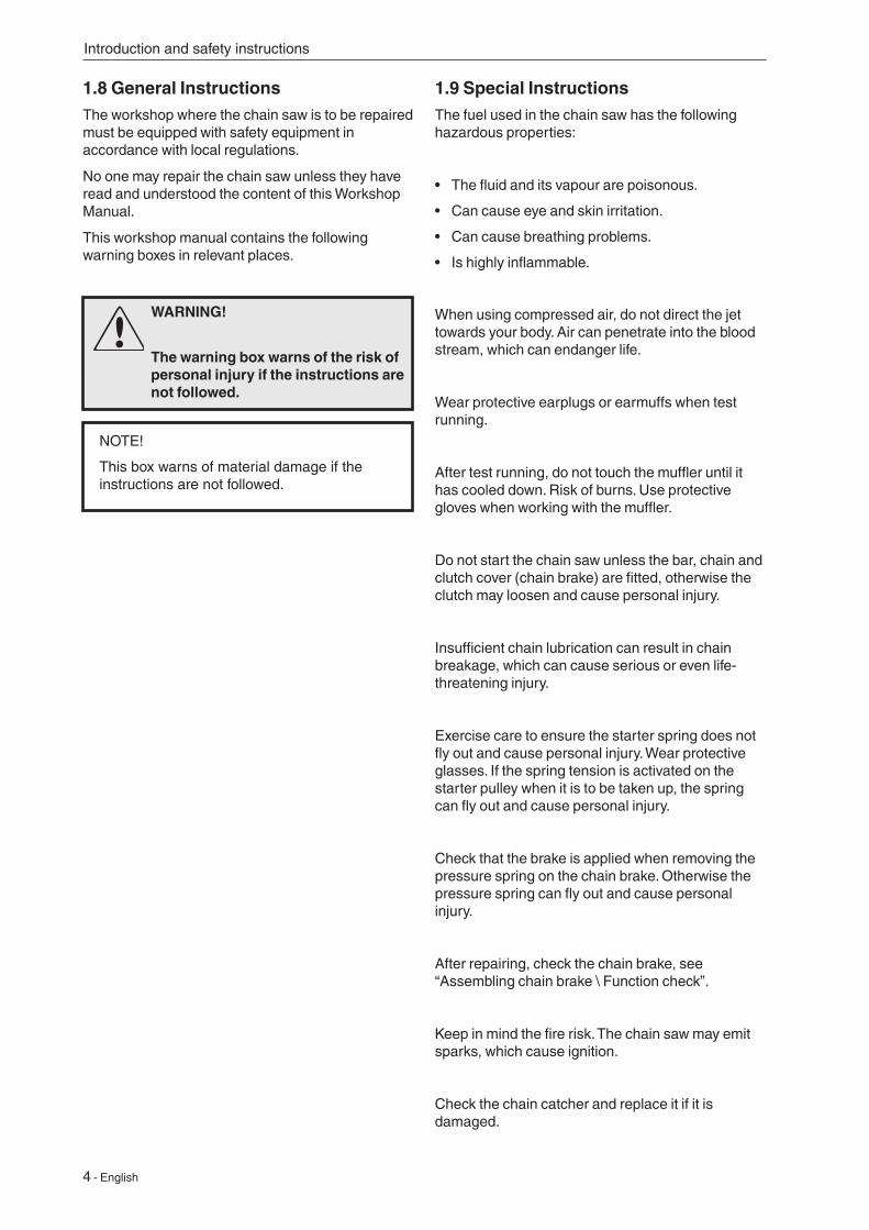
This workshop manual contains the following warning boxes in relevant places.
1.9 Special InstructionsThe fuel used in the chain saw has the following hazardous properties:
• The fluid and its vapour are poisonous.
• Can cause eye and skin irritation.
• Can cause breathing problems.
• Is highly inflammable.
When using compressed air, do not direct the jet towards your body. Air can penetrate into the blood stream, which can endanger life.
Wear protective earplugs or earmuffs when test running.
After test running, do not touch the muffler until it has cooled down. Risk of burns. Use protective gloves when working with the muffler.
Do not start the chain saw unless the bar, chain and clutch cover (chain brake) are fitted, otherwise the clutch may loosen and cause personal injury.
Insufficient chain lubrication can result in chain breakage, which can cause serious or even life-threatening injury.
Exercise care to ensure the starter spring does not fly out and cause personal injury. Wear protective glasses. If the spring tension is activated on the starter pulley when it is to be taken up, the spring can fly out and cause personal injury.
Check that the brake is applied when removing the pressure spring on the chain brake. Otherwise the pressure spring can fly out and cause personal injury.
After repairing, check the chain brake, see “Assembling chain brake \ Function check”.
Keep in mind the fire risk. The chain saw may emit sparks, which cause ignition.
Check the chain catcher and replace it if it is damaged.
WARNING!
The warning box warns of the risk of personal injury if the instructions are not followed.
NOTE!
This box warns of material damage if the instructions are not followed.
Introduction and safety instructions
English - 5
Introduction and safety instructions
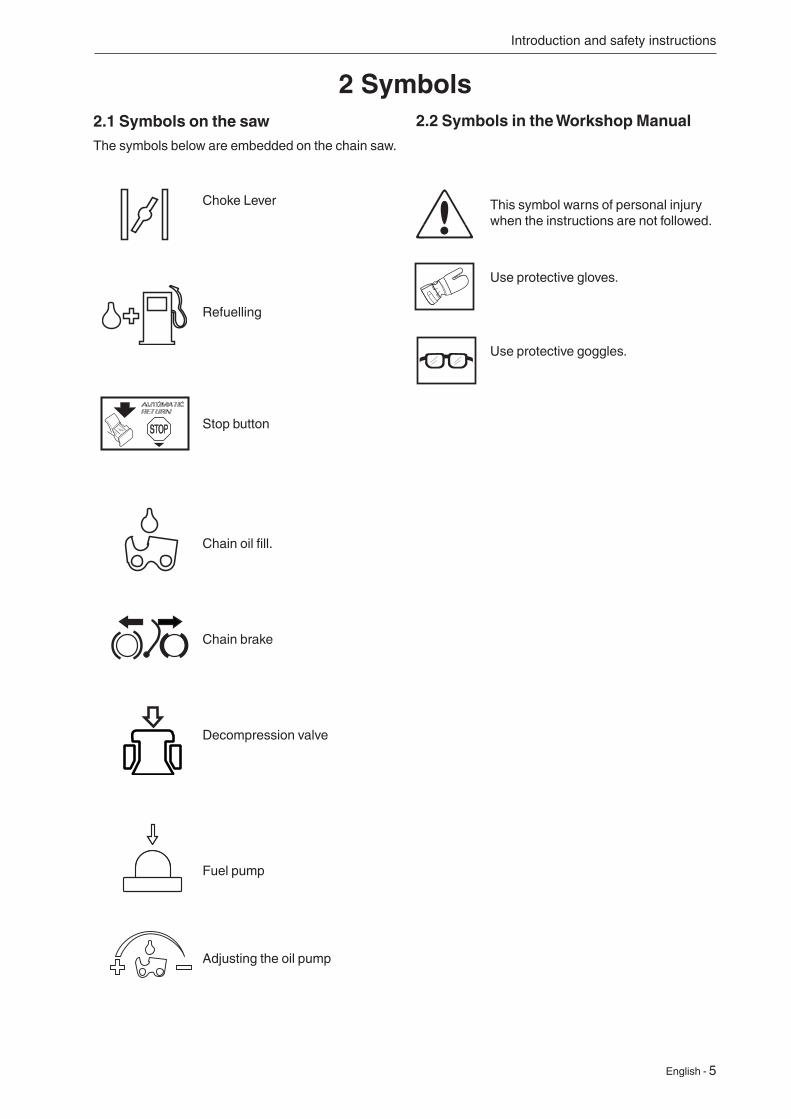
2.1 Symbols on the sawThe symbols below are embedded on the chain saw.
Choke Lever
Refuelling
Stop button
Chain oil fill.
Chain brake
Decompression valve
Fuel pump
Adjusting the oil pump
2.2 Symbols in the Workshop Manual
This symbol warns of personal injury when the instructions are not followed.
Use protective gloves.
Use protective goggles.
2 Symbols
6 - English
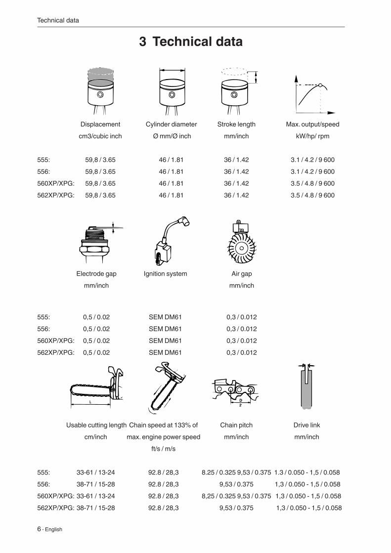
Displacement Cylinder diameter Stroke length Max. output/speed
cm3/cubic inch Ø mm/Ø inch mm/inch kW/hp/ rpm
555: 59,8 / 3.65 46 / 1.81 36 / 1.42 3.1 / 4.2 / 9 600
556: 59,8 / 3.65 46 / 1.81 36 / 1.42 3.1 / 4.2 / 9 600
560XP/XPG: 59,8 / 3.65 46 / 1.81 36 / 1.42 3.5 / 4.8 / 9 600
562XP/XPG: 59,8 / 3.65 46 / 1.81 36 / 1.42 3.5 / 4.8 / 9 600
Electrode gap Ignition system Air gap
mm/inch mm/inch
555: 0,5 / 0.02 SEM DM61 0,3 / 0.012
556: 0,5 / 0.02 SEM DM61 0,3 / 0.012
560XP/XPG: 0,5 / 0.02 SEM DM61 0,3 / 0.012
562XP/XPG: 0,5 / 0.02 SEM DM61 0,3 / 0.012
Usable cutting length Chain speed at 133% of Chain pitch Drive link
cm/inch max. engine power speed mm/inch mm/inch
ft/s / m/s
555: 33-61 / 13-24 92.8 / 28,3 8.25 / 0.325 9,53 / 0.375 1.3 / 0.050 - 1,5 / 0.058
556: 38-71 / 15-28 92.8 / 28,3 9,53 / 0.375 1,3 / 0.050 - 1,5 / 0.058
560XP/XPG: 33-61 / 13-24 92.8 / 28,3 8,25 / 0.325 9,53 / 0.375 1,3 / 0.050 - 1,5 / 0.058
562XP/XPG: 38-71 / 15-28 92.8 / 28,3 9,53 / 0.375 1,3 / 0.050 - 1,5 / 0.058
3 Technical data
Technical data
English - 7
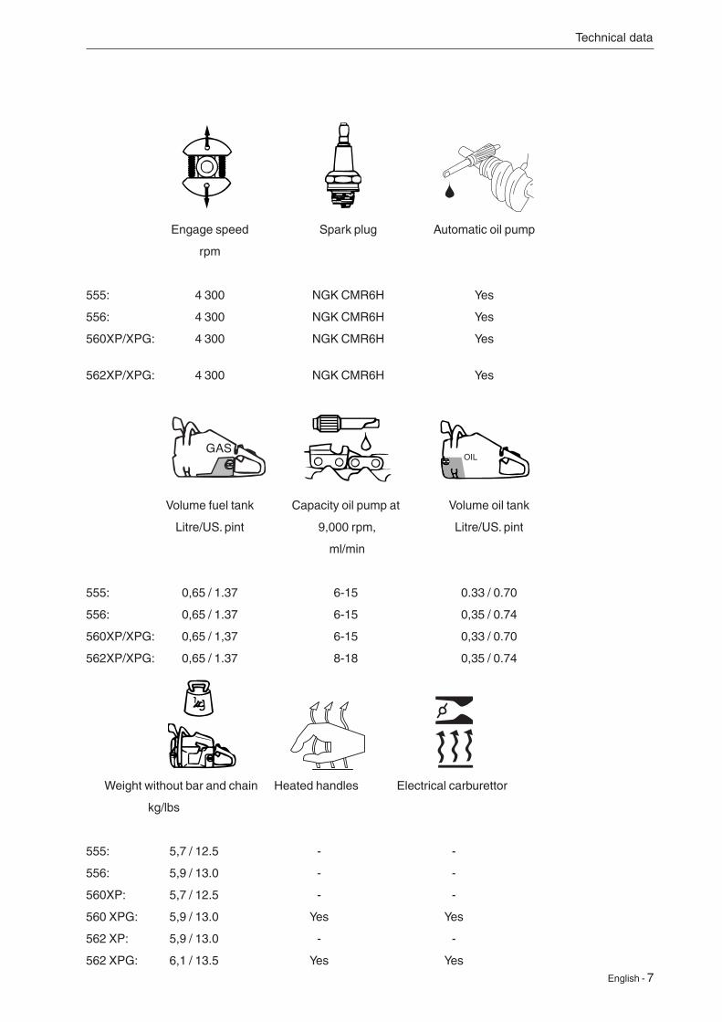
Engage speed Spark plug Automatic oil pump
rpm
555: 4 300 NGK CMR6H Yes
556: 4 300 NGK CMR6H Yes
560XP/XPG: 4 300 NGK CMR6H Yes
562XP/XPG: 4 300 NGK CMR6H Yes
Volume fuel tank Capacity oil pump at Volume oil tank
Litre/US. pint 9,000 rpm, Litre/US. pint
ml/min
555: 0,65 / 1.37 6-15 0.33 / 0.70
556: 0,65 / 1.37 6-15 0,35 / 0.74
560XP/XPG: 0,65 / 1,37 6-15 0,33 / 0.70
562XP/XPG: 0,65 / 1.37 8-18 0,35 / 0.74
Weight without bar and chain Heated handles Electrical carburettor
kg/lbs
555: 5,7 / 12.5 - -
556: 5,9 / 13.0 - -
560XP: 5,7 / 12.5 - -
560 XPG: 5,9 / 13.0 Yes Yes
562 XP: 5,9 / 13.0 - -
562 XPG: 6,1 / 13.5 Yes Yes
OIL
Technical data
8 - English
6a
10 11
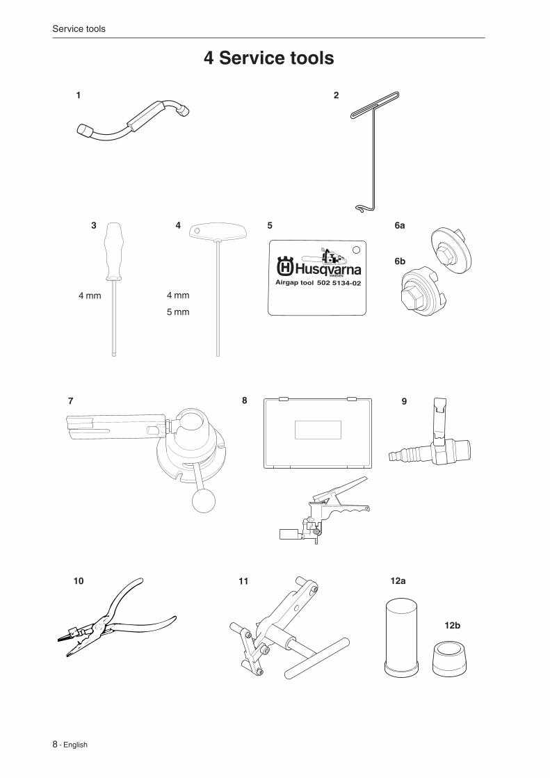
4 Service tools
Service tools
3 5
8
1 2
7 9
4 mm
5 mm
4
4 mm
12a
12b
6b
English - 9
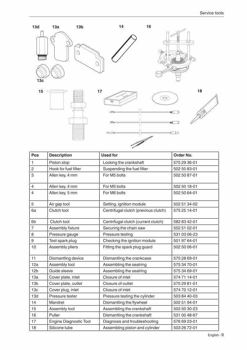
Pos Description Used for Order No.
1 Piston stop Locking the crankshaft 575 29 36-01
2 Hook for fuel filter Suspending the fuel filter 502 50 83-01
3 Allen key, 4 mm For M5 bolts 502 50 87-01
4 Allen key, 4 mm For M5 bolts 502 50 18-01
4 Allen key, 5 mm For M6 bolts 502 50 64-01
5 Air gap tool Setting, ignition module 502 51 34-02
6a Clutch tool Centrifugal clutch (previous clutch) 575 25 14-01
6b Clutch tool Centrifugal clutch (current clutch) 582 83 42-01
7 Assembly fixture Securing the chain saw 502 51 02-01
8 Pressure gauge Pressure testing 531 03 06-23
9 Test spark plug Checking the ignition module 501 97 64-01
10 Assembly pliers Fitting the spark plug guard 502 50 06-01
11 Dismantling device Dismantling the crankcase 575 28 69-01
12a Assembly tool Assembling the sealring 575 34 70-01
12b Guide sleeve Assembling the sealring 575 34 69-01
13a Cover plate, inlet Closure of inlet 574 71 14-01
13b Cover plate, outlet Closure of outlet 575 29 81-01
13c Cover plug, inlet Closure of inlet 574 70 12-01
13d Pressure tester Pressure testing the cylinder 503 84 40-03
14 Mandrel Dismantling the flywheel 502 51 94-01
15 Assembly tool Assembling the crankshaft 502 50 30-23
16 Puller Dismantling the crankshaft 531 00 48-67
17 Engine Diagnostic Tool Diagnosis and troubleshooting 576 69 23-01
18 Silicone tube Assembling piston and cylinder 503 26 72-01
Service tools
14
13c
13b 16
17
13a13d
15 18
10 - English
14-16Nm 5mm
1,5-2Nm 4mm
5-6Nm 4mm
25Nm
1-2Nm
8-10Nm 4mm
4-5Nm 4mm
18-20Nm 16mm
16-20Nm 5mm
11-13Nm 13mm
12-14Nm 13mm
1-2Nm
1-3Nm
1-2Nm
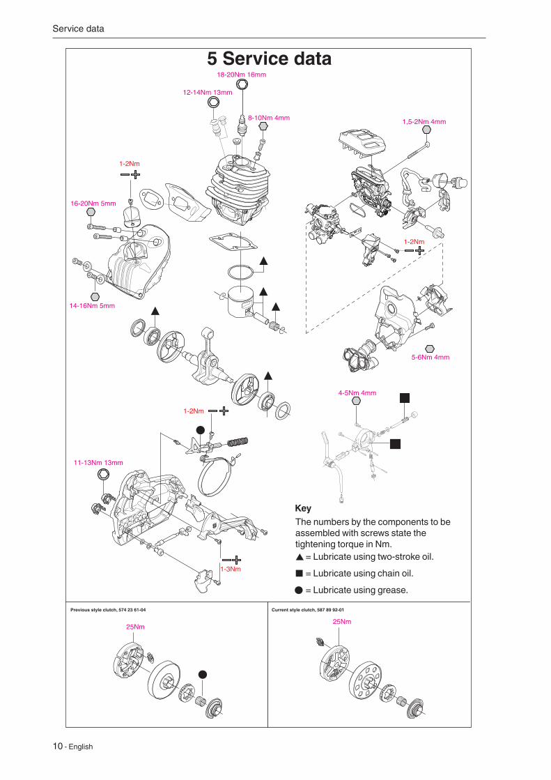
Previous style clutch, 574 23 61-04 Current style clutch, 587 89 92-01
25Nm
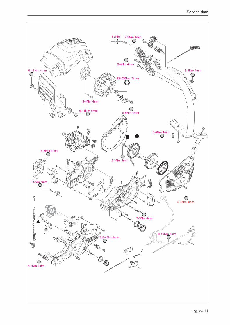
5 Service data
Service data
= Lubricate using two-stroke oil.
= Lubricate using chain oil.
= Lubricate using grease.
The numbers by the components to be assembled with screws state the tightening torque in Nm.
Key
English - 11
Service data
5-6Nm 4mm
3,5-4Nm 4mm
5-6Nm 4mm
6-8Nm 4mm
7-9Nm 4mm
6-8Nm 4mm
22-25Nm 13mm
9-11Nm 4mm
3-4Nm 4mm
7-9Nm 4mm
3-4Nm 4mm
3-4Nm 4mm
2-3Nm 4mm
1-2Nm
3-4Nm 4mm9-11Nm 4mm
8-10Nm 4mm
3-4Nm 4mm
English - 12
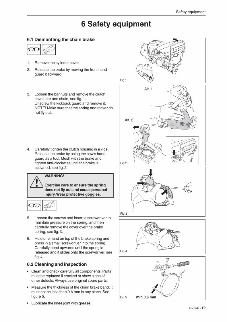
4. Carefully tighten the clutch housing in a vice. Release the brake by using the saw’s hand guard as a tool. Mesh with the brake and tighten anti-clockwise until the brake is activated, see fig. 2.
WARNING! Exercise care to ensure the spring does not fly out and cause personal injury. Wear protective goggles.
3. Loosen the bar nuts and remove the clutch cover, bar and chain, see fig. 1. Unscrew the kickback guard and remove it.NOTE! Make sure that the spring and rocker do not fly out.
5. Loosen the screws and insert a screwdriver to maintain pressure on the spring, and then carefully remove the cover over the brake spring, see fig. 3.
6. Hold one hand on top of the brake spring and press in a small screwdriver into the spring. Carefully bend upwards until the spring is released and it slides onto the screwdriver, see fig. 4.
6.2 Cleaning and inspection• Clean and check carefully all components. Parts
must be replaced if cracked or show signs of other defects. Always use original spare parts.
• Measure the thickness of the chain brake band. It must not be less than 0.6 mm in any place. See figure 5.
• Lubricate the knee joint with grease.
Safety equipment
6 Safety equipment
6.1 Dismantling the chain brake
1. Remove the cylinder cover.
2. Release the brake by moving the front hand guard backward.
Fig 1
Fig 2
Fig 3
Fig 4
Fig 5
Alt. 1
Alt. 2
13 - English
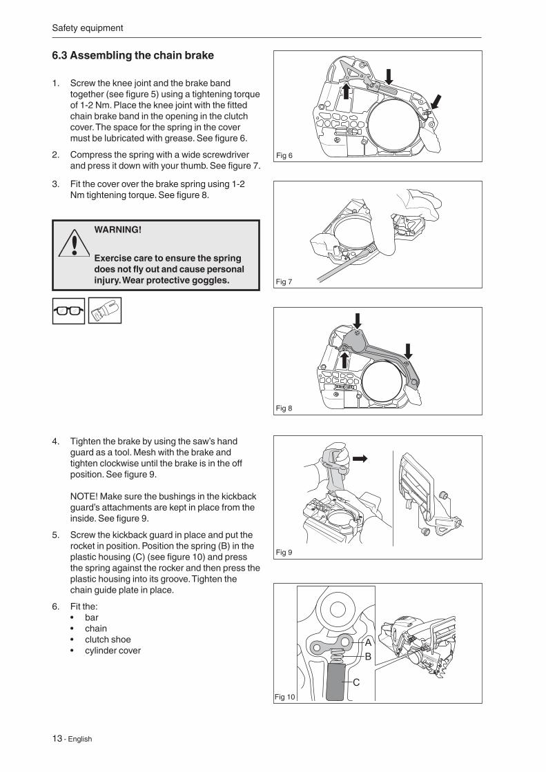
6.3 Assembling the chain brake
1. Screw the knee joint and the brake band together (see figure 5) using a tightening torque of 1-2 Nm. Place the knee joint with the fitted chain brake band in the opening in the clutch cover. The space for the spring in the cover must be lubricated with grease. See figure 6.
2. Compress the spring with a wide screwdriver and press it down with your thumb. See figure 7.
3. Fit the cover over the brake spring using 1-2 Nm tightening torque. See figure 8.
WARNING!
Exercise care to ensure the spring does not fly out and cause personal injury. Wear protective goggles.
4. Tighten the brake by using the saw’s hand guard as a tool. Mesh with the brake and tighten clockwise until the brake is in the off position. See figure 9. NOTE! Make sure the bushings in the kickback guard’s attachments are kept in place from the inside. See figure 9.
5. Screw the kickback guard in place and put the rocket in position. Position the spring (B) in the plastic housing (C) (see figure 10) and press the spring against the rocker and then press the plastic housing into its groove. Tighten the chain guide plate in place.
6. Fit the: • bar • chain • clutch shoe • cylinder cover
Safety equipment
Fig 6
Fig 7
Fig 8
Fig 9
AB
CFig 10
English - 14
NOTE!
After repairing, the chain brake must be inspected in line with the instruction below.
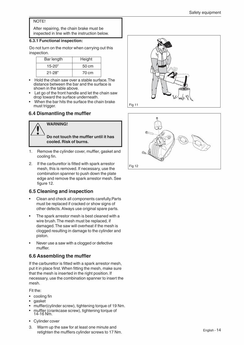
6.3.1 Functional inspection:
Do not turn on the motor when carrying out this inspection.
Bar length Height
15-20” 50 cm
• Hold the chain saw over a stable surface. The distance between the bar and the surface is shown in the table above.
• Let go of the front handle and let the chain saw drop toward the surface underneath.
• When the bar hits the surface the chain brake must trigger.
Safety equipment
6.4 Dismantling the muffler
1. Remove the cylinder cover, muffler, gasket and cooling fin.
2. If the carburettor is fitted with spark arrestor mesh, this is removed. If necessary, use the combination spanner to push down the plate edge and remove the spark arrestor mesh. See figure 12.
6.5 Cleaning and inspection• Clean and check all components carefully.Parts
must be replaced if cracked or show signs of other defects. Always use original spare parts.
• The spark arrestor mesh is best cleaned with a wire brush. The mesh must be replaced, if damaged. The saw will overheat if the mesh is clogged resulting in damage to the cylinder and piston.
• Never use a saw with a clogged or defective muffler.
6.6 Assembling the mufflerIf the carburettor is fitted with a spark arrestor mesh, put it in place first. When fitting the mesh, make sure that the mesh is inserted in the right position. If necessary, use the combination spanner to insert the mesh.
Fit the:• cooling fin• gasket• muffler(cylinder screw), tightening torque of 19 Nm.• muffler (crankcase screw), tightening torque of
14-16 Nm.
• Cylinder cover
3. Warm up the saw for at least one minute and retighten the mufflers cylinder screws to 17 Nm.
WARNING!
Do not touch the muffler until it has cooled. Risk of burns.
Fig 12
Fig 11
21-28” 70 cm

15 - English
6.7 Replacing the chain catcherA worn chain catcher must always be replaced with a new one. Always use original spare parts.
1. Release the brake by moving the front hand guard backward.
2. Loosen the bar nuts and remove the clutch cover, chain and bar.
3. Remove the chain catcher and replace it with a new one.
4. Make sure that the vibration element is fitted correctly on the crankcase when a new chain catcher is screwed in place. See figure 13.
Safety equipment
6.8 Dismantling the start/stop control1. Remove the cylinder cover and air filter.
Dismantle the air filter holder. See the “Dismantling the carburettor” chapter.
2. Loosen screw B and dismantle the stop control A. See figure 14. Unhook the rubber collar around the control from the guide plugs.
6.9 Cleaning and inspection• Clean and check carefully all components.
Parts must be replaced if cracked or show signs of other defects. Always use original spare parts.
Fig 13
Fig 14
English - 16
Safety equipment
“Dismantling the ignition module and flywheel”.
5. Cut open the shrink tube covering both cables and shrink tubing that encloses the cable ends.
6. Clean the contact areas and check resistance in the following way;
7. Test the resistance by connecting a multimeter to the cable ends.
8. The stop switch is in the “on” position when the button is held down (see figure 17) and in the “off” position when the button is in neutral.
9. Resistance can be 0.5 Ohm at most with the power switch in the “on” position.
10. When assembling (see figure 18), pull the cable ends apart and slide on a thicker shrink tube over both cables. Then slide on the thinner shrink tubes over each cable. Connect the cable ends together. Slide the thinner shrink tubes over the cable ends and heat the shrink tube first on both cables separately. Slide the thicker shrink tube over the thinner shrink tubes and then heat the thicker shrink tube.
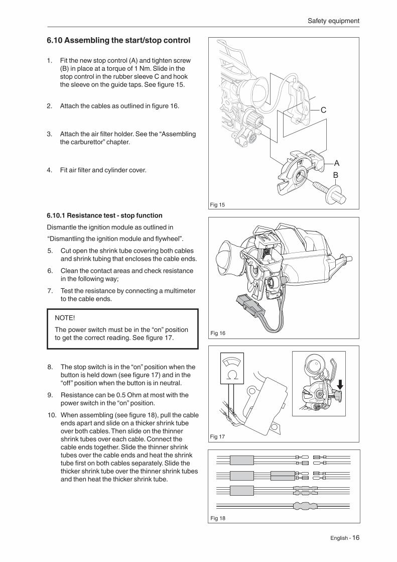
6.10 Assembling the start/stop control
1. Fit the new stop control (A) and tighten screw (B) in place at a torque of 1 Nm. Slide in the stop control in the rubber sleeve C and hook the sleeve on the guide taps. See figure 15.
Fig 15
Fig 16
2. Attach the cables as outlined in figure 16.
3. Attach the air filter holder. See the “Assembling the carburettor” chapter.
4. Fit air filter and cylinder cover.
6.10.1 Resistance test - stop function
Dismantle the ignition module as outlined in
Fig 18
Fig 17
NOTE!
The power switch must be in the “on” position to get the correct reading. See figure 17.
17 - English
Safety equipment
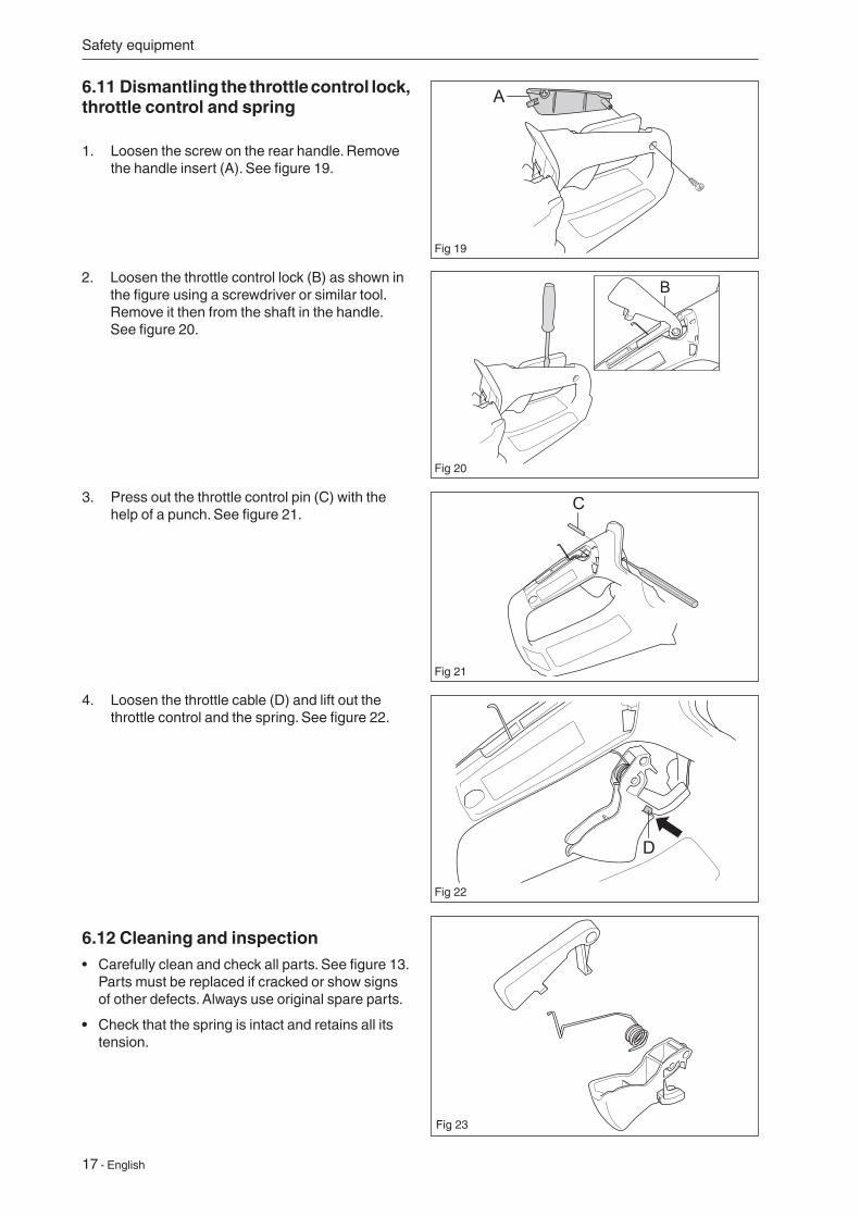
3. Press out the throttle control pin (C) with the help of a punch. See figure 21.
4. Loosen the throttle cable (D) and lift out the throttle control and the spring. See figure 22.
6.11 Dismantling the throttle control lock, throttle control and spring
1. Loosen the screw on the rear handle. Remove the handle insert (A). See figure 19.
6.12 Cleaning and inspection• Carefully clean and check all parts. See figure 13.
Parts must be replaced if cracked or show signs of other defects. Always use original spare parts.
• Check that the spring is intact and retains all its tension.
Fig 20
Fig 21
Fig 22
Fig 23
Fig 19
A
2. Loosen the throttle control lock (B) as shown in the figure using a screwdriver or similar tool. Remove it then from the shaft in the handle. See figure 20.
English - 18
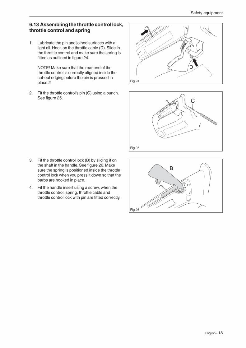
6.13 Assembling the throttle control lock, throttle control and spring
1. Lubricate the pin and joined surfaces with a light oil. Hook on the throttle cable (D). Slide in the throttle control and make sure the spring is fitted as outlined in figure 24. NOTE! Make sure that the rear end of the throttle control is correctly aligned inside the cut-out edging before the pin is pressed in place.2
Safety equipment
Fig 24
Fig 25
Fig 26
C2. Fit the throttle control’s pin (C) using a punch.
See figure 25.
3. Fit the throttle control lock (B) by sliding it on the shaft in the handle. See figure 26. Make sure the spring is positioned inside the throttle control lock when you press it down so that the barbs are hooked in place.
4. Fit the handle insert using a screw, when the throttle control, spring, throttle cable and throttle control lock with pin are fitted correctly.
English - 19
Repair Instructions
WARNING!
If the spring tension is activated on the starter pulley, the spring can fly out and cause personal injury. Wear protective glasses.
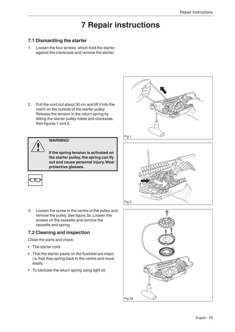
7.1 Dismantling the starter1. Loosen the four screws, which hold the starter
against the crankcase and remove the starter.
3. Loosen the screw in the centre of the pulley and remove the pulley. See figure 3a. Loosen the screws on the cassette and remove the cassette and spring.
7.2 Cleaning and inspectionClean the parts and check:
• The starter cord.
• That the starter pawls on the flywheel are intact, i.e. that they spring back to the centre and move easily.
• To lubricate the return spring using light oil.
7 Repair instructions
2. Pull the cord out about 30 cm and lift it into the notch on the outside of the starter pulley. Release the tension in the return spring by letting the starter pulley rotate anti-clockwise. See figures 1 and 2.
Fig 1
Fig 2
Fig 3a
20 - English
Repair instructions
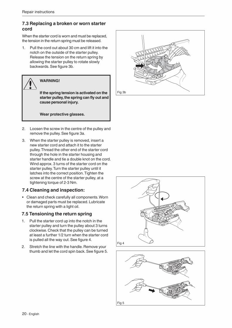
7.3 Replacing a broken or worn starter cordWhen the starter cord is worn and must be replaced, the tension in the return spring must be released.
1. Pull the cord out about 30 cm and lift it into the notch on the outside of the starter pulley. Release the tension on the return spring by allowing the starter pulley to rotate slowly backwards. See figure 3b.
7.5 Tensioning the return spring1. Pull the starter cord up into the notch in the
starter pulley and turn the pulley about 3 turns clockwise. Check that the pulley can be turned at least a further 1/2 turn when the starter cord is pulled all the way out. See figure 4.
2. Stretch the line with the handle. Remove your thumb and let the cord spin back. See figure 5.
2. Loosen the screw in the centre of the pulley and remove the pulley. See figure 3a.
3. When the starter pulley is removed, insert a new starter cord and attach it to the starter pulley. Thread the other end of the starter cord through the hole in the starter housing and starter handle and tie a double knot on the cord. Wind approx. 3 turns of the starter cord on the starter pulley. Turn the starter pulley until it latches into the correct position. Tighten the screw at the centre of the starter pulley, at a tightening torque of 2-3 Nm.
7.4 Cleaning and inspection:• Clean and check carefully all components. Worn
or damaged parts must be replaced. Lubricate the return spring with a light oil.
WARNING!
If the spring tension is activated on the starter pulley, the spring can fly out and cause personal injury.
Wear protective glasses.
Fig 4
Fig 5
Fig 3b
English - 21
Repair Instructions
WARNING!
Exercise care to ensure the spring does not fly out and cause personal injury. Wear protective goggles.
7.6 Replacing a broken return spring
1. Loosen the screw at the centre of the starter pulley and loosen the screws on the cassette. Remove the starter pulley with the cassette and spring.
2. Remove the broken cassette and replace it with a new one.
3. Tighten the screw at the centre of the starter pulley, at a tightening torque of 2-3 Nm. Load the return spring, see “Loading the return spring”. See also the “Dismantling the starter” chapter.
7.7 Starter assembly
Position the starter against the crankcase and tighten the screws at a tightening torque of 3-4 Nm.
22 - English
Repair Instructions
7.8 Dismantling the ignition module and flywheel
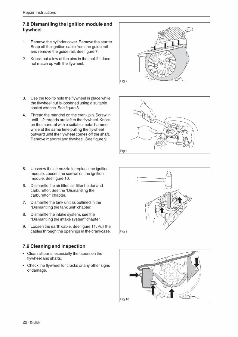
1. Remove the cylinder cover. Remove the starter. Snap off the ignition cable from the guide rail and remove the guide rail. See figure 7.
2. Knock out a few of the pins in the tool if it does not match up with the flywheel.
5. Unscrew the air nozzle to replace the ignition module. Loosen the screws on the ignition module. See figure 10.
6. Dismantle the air filter, air filter holder and carburettor. See the “Dismantling the carburettor” chapter.
7. Dismantle the tank unit as outlined in the “Dismantling the tank unit” chapter.
8. Dismantle the intake system, see the “Dismantling the intake system” chapter.
9. Loosen the earth cable. See figure 11. Pull the cables through the openings in the crankcase.
7.9 Cleaning and inspection• Clean all parts, especially the tapers on the
flywheel and shafts.
• Check the flywheel for cracks or any other signs of damage.
3. Use the tool to hold the flywheel in place while the flywheel nut is loosened using a suitable socket wrench. See figure 8.
4. Thread the mandrel on the crank pin. Screw in until 1-2 threads are left to the flywheel. Knock on the mandrel with a suitable metal hammer while at the same time pulling the flywheel outward until the flywheel comes off the shaft. Remove mandrel and flywheel. See figure 9.
Fig 7
Fig 8
Fig 9
Fig 10
English - 23
Repair Instructions
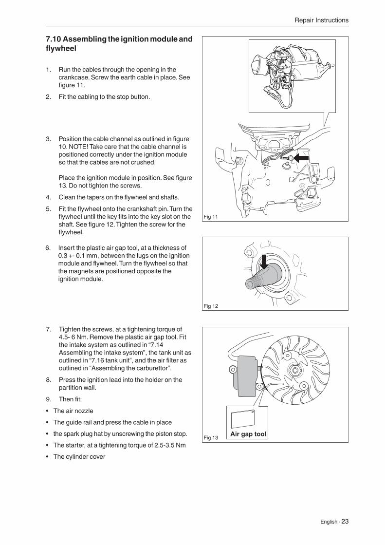
7.10 Assembling the ignition module and flywheel
1. Run the cables through the opening in the crankcase. Screw the earth cable in place. See figure 11.
2. Fit the cabling to the stop button.
3. Position the cable channel as outlined in figure 10. NOTE! Take care that the cable channel is positioned correctly under the ignition module so that the cables are not crushed. Place the ignition module in position. See figure 13. Do not tighten the screws.
4. Clean the tapers on the flywheel and shafts.
5. Fit the flywheel onto the crankshaft pin. Turn the flywheel until the key fits into the key slot on the shaft. See figure 12. Tighten the screw for the flywheel.
Fig 12
Fig 13
6. Insert the plastic air gap tool, at a thickness of 0.3 +- 0.1 mm, between the lugs on the ignition module and flywheel. Turn the flywheel so that the magnets are positioned opposite the ignition module.
7. Tighten the screws, at a tightening torque of 4.5- 6 Nm. Remove the plastic air gap tool. Fit the intake system as outlined in “7.14 Assembling the intake system”, the tank unit as outlined in “7.16 tank unit”, and the air filter as outlined in “Assembling the carburettor”.
8. Press the ignition lead into the holder on the partition wall.
9. Then fit:
• The air nozzle
• The guide rail and press the cable in place
• the spark plug hat by unscrewing the piston stop.
• The starter, at a tightening torque of 2.5-3.5 Nm
• The cylinder cover
Fig 11
24 - English
Repair Instructions
NOTE!
Be careful with the clutch springs, as opening them too much can result in material damage.
7.11 Cleaning and inspection• Clean and check all parts carefully. Parts must be
replaced if cracked or showing signs of other defects. Always use original spare parts.
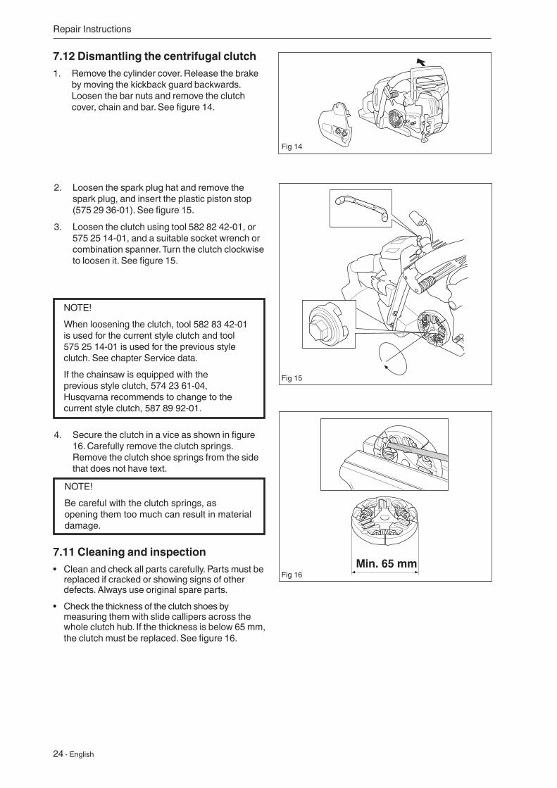
• Check the thickness of the clutch shoes by measuring them with slide callipers across the whole clutch hub. If the thickness is below 65 mm, the clutch must be replaced. See figure 16.
2. Loosen the spark plug hat and remove the spark plug, and insert the plastic piston stop (575 29 36-01). See figure 15.
3. Loosen the clutch using tool 582 82 42-01, or 575 25 14-01, and a suitable socket wrench or combination spanner. Turn the clutch clockwise to loosen it. See figure 15.
4. Secure the clutch in a vice as shown in figure 16. Carefully remove the clutch springs. Remove the clutch shoe springs from the side that does not have text.
Min. 65 mm
7.12 Dismantling the centrifugal clutch1. Remove the cylinder cover. Release the brake
by moving the kickback guard backwards. Loosen the bar nuts and remove the clutch cover, chain and bar. See figure 14.
Fig 14
Fig 16
Fig 15
NOTE!
When loosening the clutch, tool 582 83 42-01 is used for the current style clutch and tool 575 25 14-01 is used for the previous style clutch. See chapter Service data.
If the chainsaw is equipped with the previous style clutch, 574 23 61-04, Husqvarna recommends to change to the current style clutch, 587 89 92-01.
English - 25
7.13 Assembly of centrifugal clutch
1. Insert the clutch springs on the side of the shoes without text. See figure 17.
2. Loosen the spark plug hat and remove the spark plug, and insert the plastic piston stop (575 29 36-01). See figure 15.
3. Screw in the clutch (anti-clockwise) until it stops. Then tighten the clutch using tool 575 25 14-01, or 582 83 42-01, and a suitable socket wrench or combination spanner. Tightening torque 25 Nm.
NOTE!
When loosening the clutch, tool 582 83 42-01 is used for the current style clutch and tool 575 25 14-01 is used for the previous style clutch. See chapter Service data.
If the chainsaw is equipped with the previous style clutch, 574 23 61-04, Husqvarna recommends to change to the current style clutch, 587 89 92-01.
4. Remove the piston stop and fit the spark plug using a tightening torque of 18-20 Nm and the spark plug hat.
5. Then fit:
• The cylinder cover
• The bar
• The chain
• The clutch cover
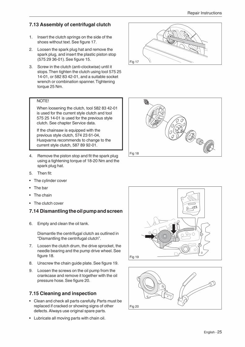
7.14 Dismantling the oil pump and screen
6. Empty and clean the oil tank. Dismantle the centrifugal clutch as outlined in “Dismantling the centrifugal clutch”.
7. Loosen the clutch drum, the drive sprocket, the needle bearing and the pump drive wheel. See figure 18.
8. Unscrew the chain guide plate. See figure 19.
9. Loosen the screws on the oil pump from the crankcase and remove it together with the oil pressure hose. See figure 20.
7.15 Cleaning and inspection• Clean and check all parts carefully. Parts must be
replaced if cracked or showing signs of other defects. Always use original spare parts.
• Lubricate all moving parts with chain oil.
Repair Instructions
Fig 17
Fig 19
Fig 18
Fig 20
26 - English
D D
D
D
E
Repair Instructions
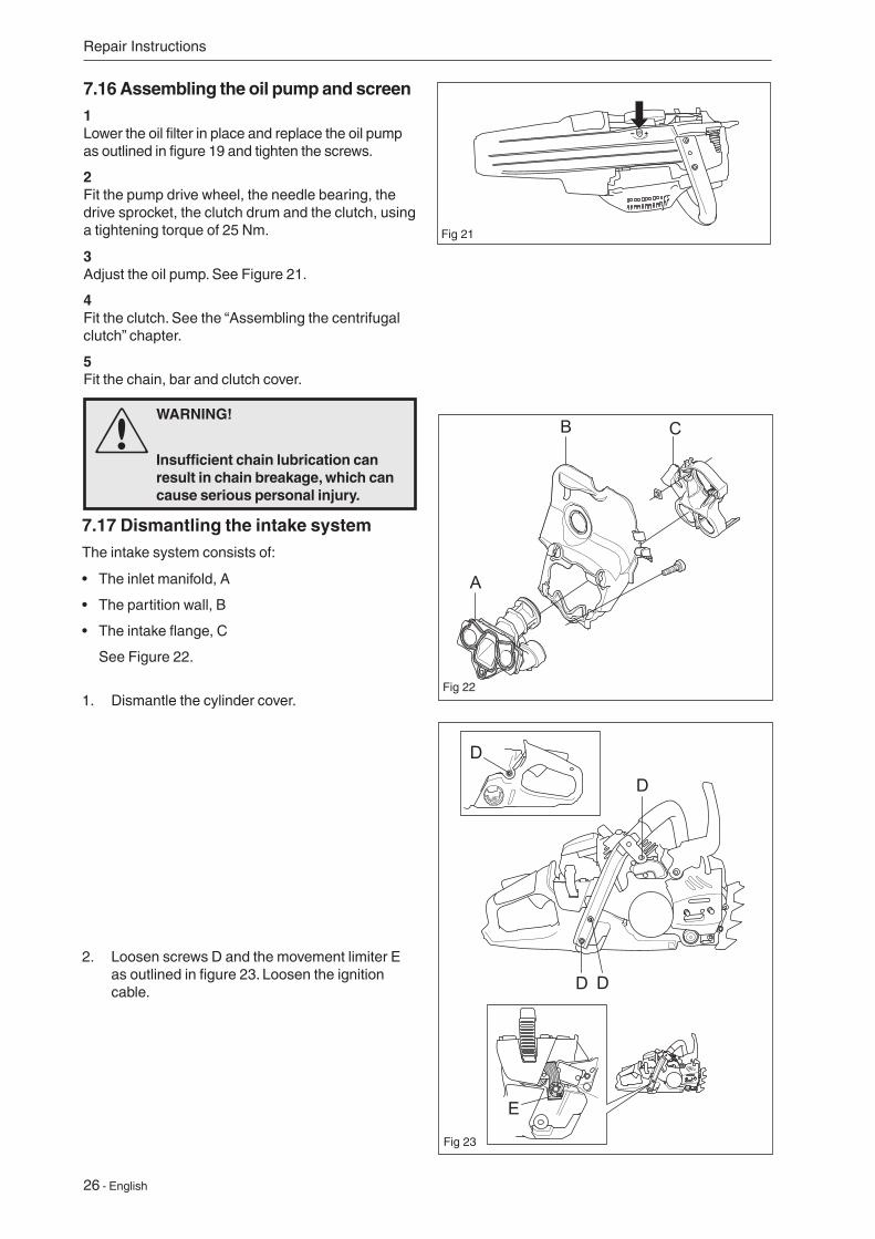
7.16 Assembling the oil pump and screen1Lower the oil filter in place and replace the oil pump as outlined in figure 19 and tighten the screws.
2Fit the pump drive wheel, the needle bearing, the drive sprocket, the clutch drum and the clutch, using a tightening torque of 25 Nm.
3Adjust the oil pump. See Figure 21.
4Fit the clutch. See the “Assembling the centrifugal clutch” chapter.
5Fit the chain, bar and clutch cover.
WARNING!
Insufficient chain lubrication can result in chain breakage, which can cause serious personal injury.
7.17 Dismantling the intake systemThe intake system consists of:
• The inlet manifold, A
• The partition wall, B
• The intake flange, C
See Figure 22.
1. Dismantle the cylinder cover.
2. Loosen screws D and the movement limiter E as outlined in figure 23. Loosen the ignition cable.
B
A
C
Fig 21
Fig 22
Fig 23
English - 27
Repair Instructions
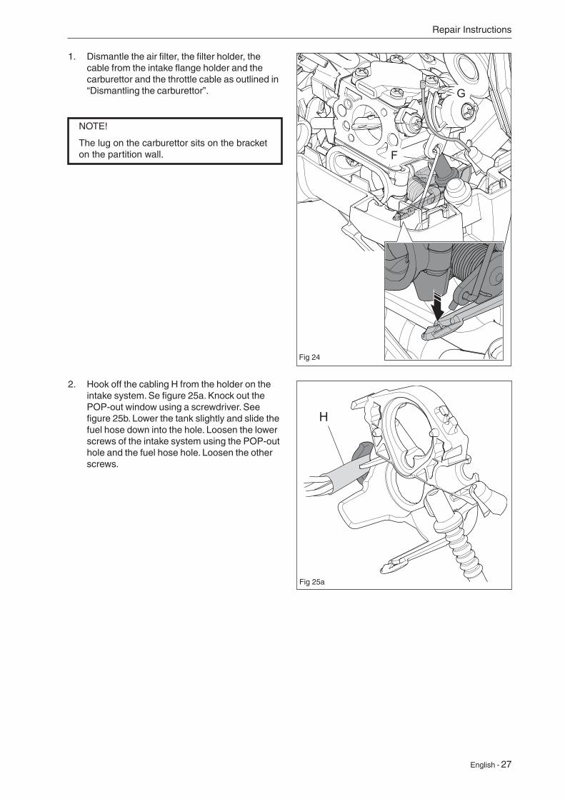
1. Dismantle the air filter, the filter holder, the cable from the intake flange holder and the carburettor and the throttle cable as outlined in “Dismantling the carburettor”.
Fig 24
2. Hook off the cabling H from the holder on the intake system. Se figure 25a. Knock out the POP-out window using a screwdriver. See figure 25b. Lower the tank slightly and slide the fuel hose down into the hole. Loosen the lower screws of the intake system using the POP-out hole and the fuel hose hole. Loosen the other screws.
G
F
H
Fig 25a
NOTE!
The lug on the carburettor sits on the bracket on the partition wall.
28 - English
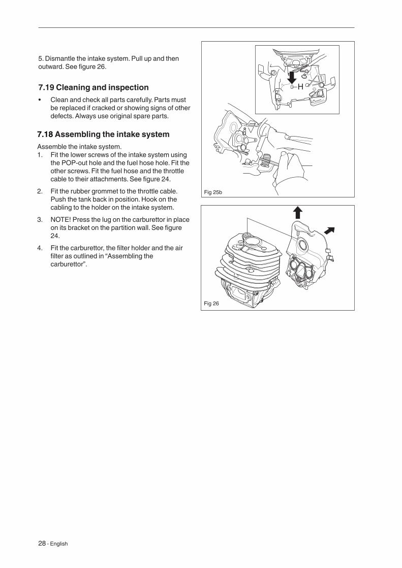
7.18 Assembling the intake systemAssemble the intake system.1. Fit the lower screws of the intake system using
the POP-out hole and the fuel hose hole. Fit the other screws. Fit the fuel hose and the throttle cable to their attachments. See figure 24.
2. Fit the rubber grommet to the throttle cable. Push the tank back in position. Hook on the cabling to the holder on the intake system.
3. NOTE! Press the lug on the carburettor in place on its bracket on the partition wall. See figure 24.
4. Fit the carburettor, the filter holder and the air filter as outlined in “Assembling the carburettor”.
7.19 Cleaning and inspection• Clean and check all parts carefully. Parts must
be replaced if cracked or showing signs of other defects. Always use original spare parts.
5. Dismantle the intake system. Pull up and then outward. See figure 26.
H
Fig 25b
Fig 26
English - 29
WARNING!
The fuel used in the chain saw has the following hazardous properties:
1. The fluid and its vapour are poisonous. 2. Can cause skin irritation. 3. Is highly inflammable.
7.20 Carburettor
7.20.1 Description
The figures accompanying this description do not correspond with the carburettor on the chain saw. They show only the principle of design and function.
7.20.2 Design
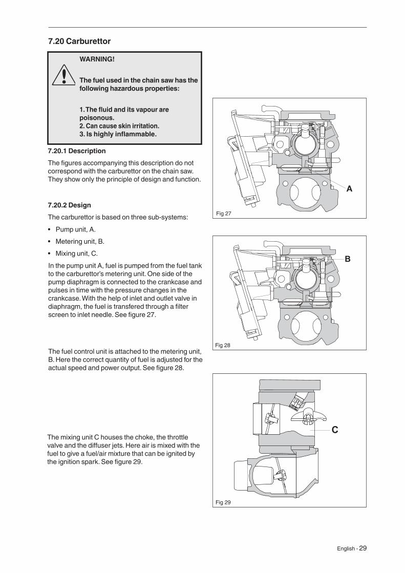
The carburettor is based on three sub-systems:
• Pump unit, A.
• Metering unit, B.
• Mixing unit, C.
The mixing unit C houses the choke, the throttle valve and the diffuser jets. Here air is mixed with the fuel to give a fuel/air mixture that can be ignited by the ignition spark. See figure 29.
C
Fig 29
In the pump unit A, fuel is pumped from the fuel tank to the carburettor’s metering unit. One side of the pump diaphragm is connected to the crankcase and pulses in time with the pressure changes in the crankcase. With the help of inlet and outlet valve in diaphragm, the fuel is transfered through a filter screen to inlet needle. See figure 27.
The fuel control unit is attached to the metering unit, B. Here the correct quantity of fuel is adjusted for the actual speed and power output. See figure 28.
A
Fig 27
B
Fig 28
30 - English
Repair Instructions
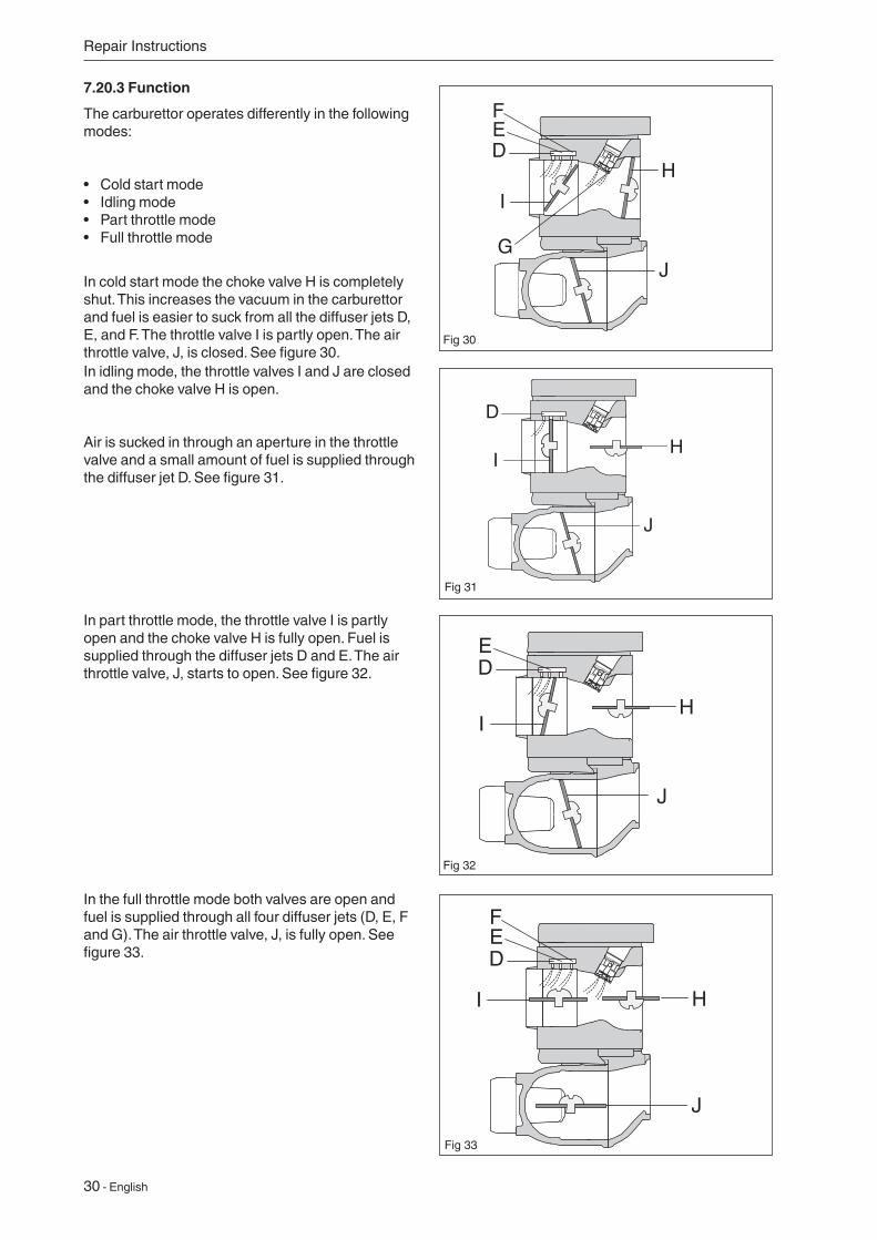
7.20.3 Function
The carburettor operates differently in the following modes:
• Cold start mode• Idling mode• Part throttle mode• Full throttle mode
In cold start mode the choke valve H is completely shut. This increases the vacuum in the carburettor and fuel is easier to suck from all the diffuser jets D, E, and F. The throttle valve I is partly open. The air throttle valve, J, is closed. See figure 30.
Fig 30
In idling mode, the throttle valves I and J are closed and the choke valve H is open.
Air is sucked in through an aperture in the throttle valve and a small amount of fuel is supplied through the diffuser jet D. See figure 31.
Fig 31
In part throttle mode, the throttle valve I is partly open and the choke valve H is fully open. Fuel is supplied through the diffuser jets D and E. The air throttle valve, J, starts to open. See figure 32.
Fig 32
In the full throttle mode both valves are open and fuel is supplied through all four diffuser jets (D, E, F and G). The air throttle valve, J, is fully open. See figure 33.
Fig 33
English - 31
Repair Instructions
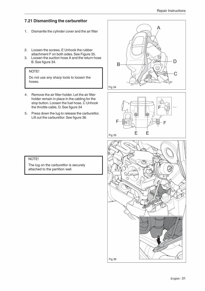
7.21 Dismantling the carburettor
1. Dismantle the cylinder cover and the air filter
2. Loosen the screws, E Unhook the rubber attachment F on both sides. See Figure 35.
E
F F
F
EFig 35
3. Loosen the suction hose A and the return hose B. See figure 34. D
C
B
A
Fig 34
4. Remove the air filter holder. Let the air filter holder remain in place in the cabling for the stop button. Loosen the fuel hose, C Unhook the throttle cable, D. See figure 34
5. Press down the lug to release the carburettor. Lift out the carburettor. See figure 36.
Fig 36
NOTE!
Do not use any sharp tools to loosen the hoses.
NOTE!
The lug on the carburettor is securely attached to the partition wall.
32 - English
Repair Instructions
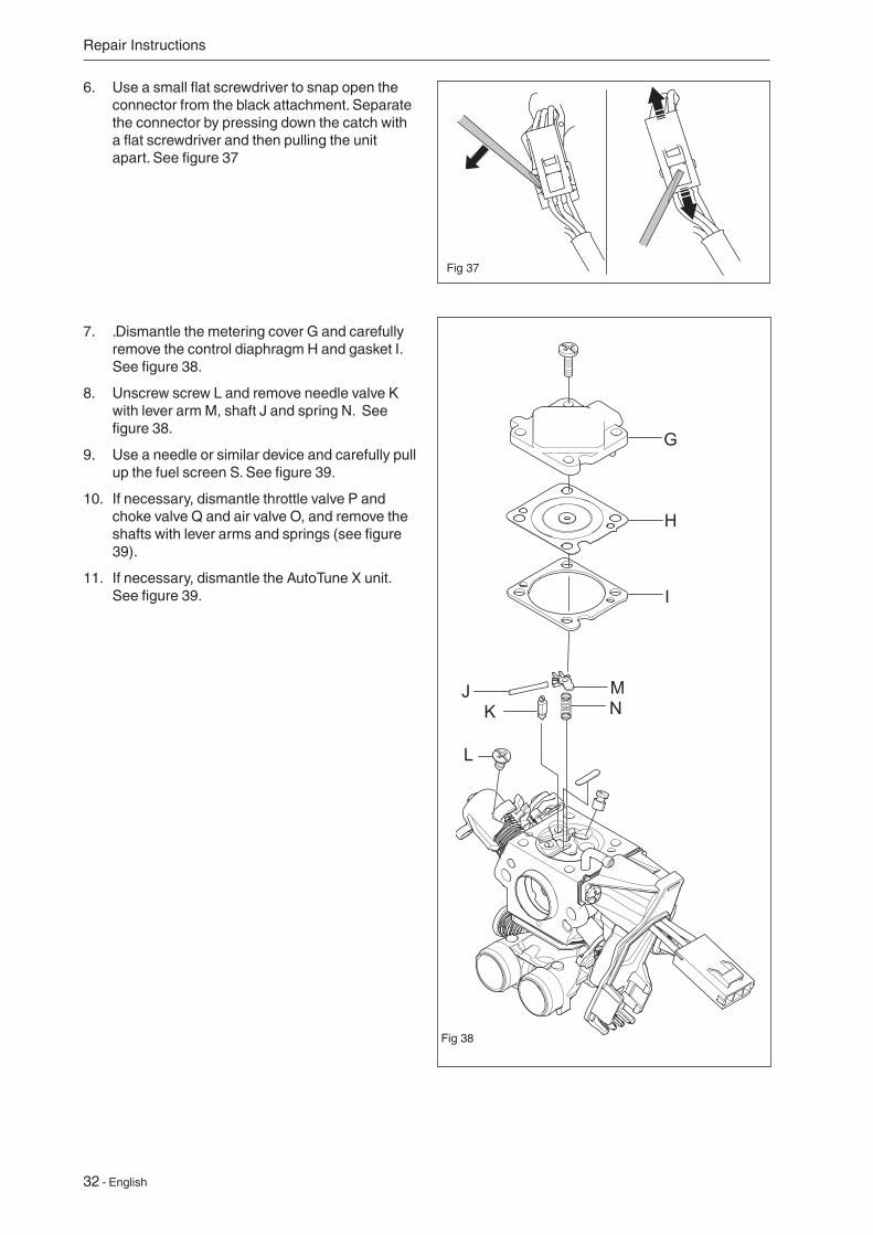
7. .Dismantle the metering cover G and carefully remove the control diaphragm H and gasket I. See figure 38.
8. Unscrew screw L and remove needle valve K with lever arm M, shaft J and spring N. See figure 38.
9. Use a needle or similar device and carefully pull up the fuel screen S. See figure 39.
10. If necessary, dismantle throttle valve P and choke valve Q and air valve O, and remove the shafts with lever arms and springs (see figure 39).
11. If necessary, dismantle the AutoTune X unit. See figure 39.
Fig 37
G
H
I
MN
JK
L
Fig 38
6. Use a small flat screwdriver to snap open the connector from the black attachment. Separate the connector by pressing down the catch with a flat screwdriver and then pulling the unit apart. See figure 37
English - 33
Repair Instructions
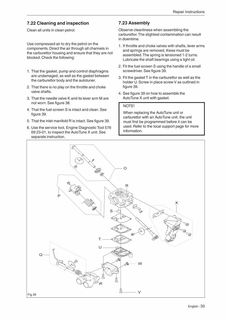
7.23 AssemblyObserve cleanliness when assembling the carburettor. The slightest contamination can result in downtime.
1. If throttle and choke valves with shafts, lever arms and springs are removed, these must be assembled. The spring is tensioned 1-2 turns. Lubricate the shaft bearings using a light oil.
2. Fit the fuel screen S using the handle of a small screwdriver. See figure 39.
3. Fit the gasket T in the carburettor as well as the holder U. Screw in place screw V as outlined in figure 39.
4. See figure 39 on how to assemble the AutoTune X unit with gasket.
7.22 Cleaning and inspectionClean all units in clean petrol.
Use compressed air to dry the petrol on the components. Direct the air through all channels in the carburettor housing and ensure that they are not blocked. Check the following:
1. That the gasket, pump and control diaphragms are undamaged, as well as the gasket between the carburettor body and the autotuner.
2. That there is no play on the throttle and choke valve shafts.
3. That the needle valve K and its lever arm M are not worn. See figure 38.
4. That the fuel screen S is intact and clean. See figure 39.
5. That the inlet manifold R is intact. See figure 39.
6. Use the service tool, Engine Diagnostic Tool 576 69 23-01, to inspect the AutoTune X unit. See separate instruction.
NOTE!
When replacing the AutoTune unit or carburettor with an AutoTune unit, the unit must first be programmed before it can be used. Refer to the local support page for more information.
O
P
S
T
Q
R
V
U
X
W
Fig 39
34 - English
Repair Instructions
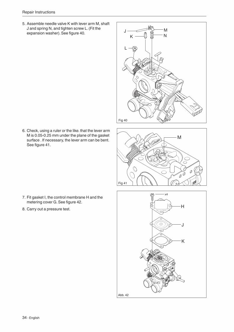
5. Assemble needle valve K with lever arm M, shaft J and spring N, and tighten screw L. (Fit the expansion washer). See figure 40.
6. Check, using a ruler or the like. that the lever arm M is 0.05-0.25 mm under the plane of the gasket surface . If necessary, the lever arm can be bent. See figure 41.
Fig 40
MN
JK
L
M
Fig 41
7. Fit gasket I, the control membrane H and the metering cover G. See figure 42.
8. Carry out a pressure test.
Abb. 42
English - 35
Repair Instructions
7.24 Adjustment of AutoTune at change of carburettorThe chainsaw will be completely adjusted automatically after a few fuellings at normal running.
- The high speed part is set during loaded running, such as cutting and felling.
-The idle part is set when the chain saw idles for some time.
Leak in Fault with
Diffuser jets Needle valve
Leak in the impulse pipe Pump membrane
Ventilation hole on the Control membrane
metering unit.
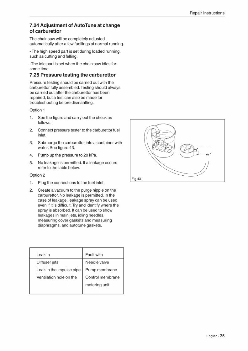
7.25 Pressure testing the carburettorPressure testing should be carried out with the carburettor fully assembled. Testing should always be carried out after the carburettor has been repaired, but a test can also be made for troubleshooting before dismantling.
Option 1
1. See the figure and carry out the check as follows:
2. Connect pressure tester to the carburettor fuel inlet.
3. Submerge the carburettor into a container with water. See figure 43.
4. Pump up the pressure to 20 kPa.
5. No leakage is permitted. If a leakage occurs refer to the table below.
Option 2
1. Plug the connections to the fuel inlet.
2. Create a vacuum to the purge nipple on the carburettor. No leakage is permitted. In the case of leakage, leakage spray can be used even if it is difficult. Try and identify where the spray is absorbed. It can be used to show leakages in main jets, idling needles, measuring cover gaskets and measuring diaphragms, and autotune gaskets.
Fig 43
36 - English
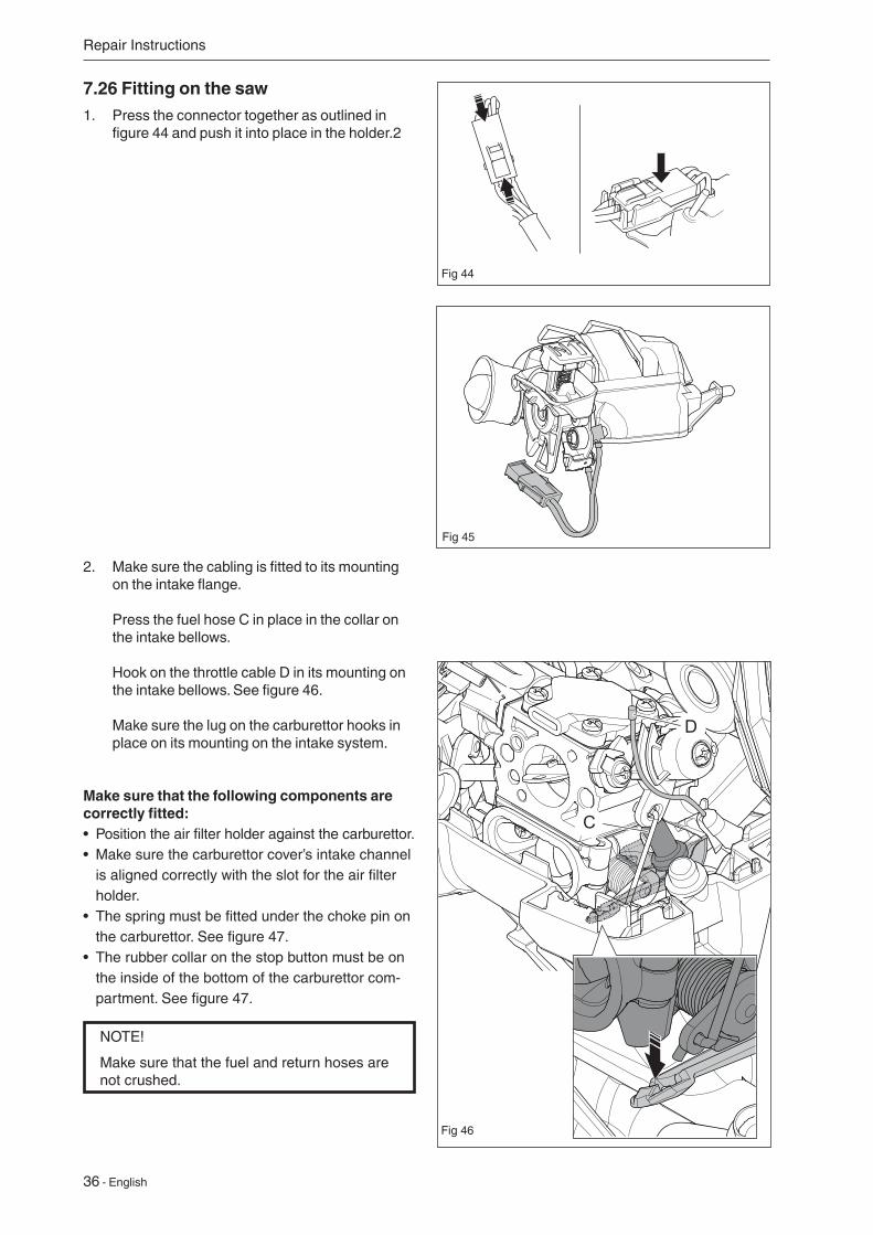
7.26 Fitting on the saw1. Press the connector together as outlined in
figure 44 and push it into place in the holder.2
Repair Instructions
Fig 44
Fig 45
2. Make sure the cabling is fitted to its mounting on the intake flange. Press the fuel hose C in place in the collar on the intake bellows. Hook on the throttle cable D in its mounting on the intake bellows. See figure 46. Make sure the lug on the carburettor hooks in place on its mounting on the intake system.
Make sure that the following components are correctly fitted:• Position the air filter holder against the carburettor.• Make sure the carburettor cover’s intake channel
is aligned correctly with the slot for the air filter holder.
• The spring must be fitted under the choke pin on the carburettor. See figure 47.
• The rubber collar on the stop button must be on the inside of the bottom of the carburettor com-partment. See figure 47.
D
C
Fig 46
NOTE!
Make sure that the fuel and return hoses are not crushed.
English - 37
Repair Instructions
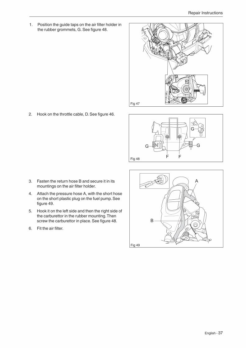
2. Hook on the throttle cable, D. See figure 46.
3. Fasten the return hose B and secure it in its mountings on the air filter holder.
4. Attach the pressure hose A, with the short hose on the short plastic plug on the fuel pump. See figure 49.
5. Hook it on the left side and then the right side of the carburettor in the rubber mounting. Then screw the carburettor in place. See figure 48.
6. Fit the air filter.
Fig 49
Fig 48
1. Position the guide taps on the air filter holder in the rubber grommets, G. See figure 48.
Fig 47
38 - English
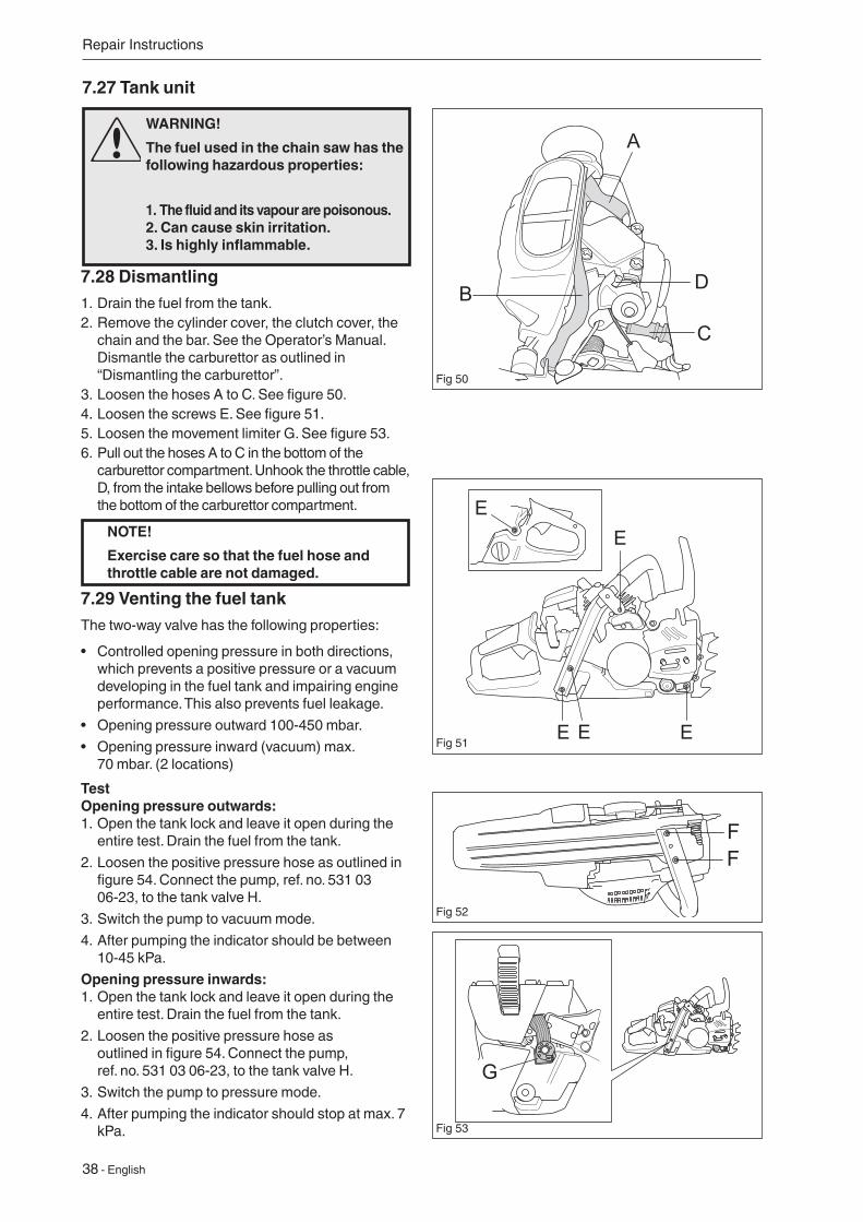
7.27 Tank unit
7.28 Dismantling1. Drain the fuel from the tank.2. Remove the cylinder cover, the clutch cover, the
chain and the bar. See the Operator’s Manual. Dismantle the carburettor as outlined in “Dismantling the carburettor”.
3. Loosen the hoses A to C. See figure 50. 4. Loosen the screws E. See figure 51.5. Loosen the movement limiter G. See figure 53.6. Pull out the hoses A to C in the bottom of the
carburettor compartment. Unhook the throttle cable, D, from the intake bellows before pulling out from the bottom of the carburettor compartment.
NOTE!
Exercise care so that the fuel hose and throttle cable are not damaged.
Repair Instructions
WARNING!
The fuel used in the chain saw has the following hazardous properties:
1. The fluid and its vapour are poisonous. 2. Can cause skin irritation. 3. Is highly inflammable.
7.29 Venting the fuel tankThe two-way valve has the following properties:
• Controlled opening pressure in both directions, which prevents a positive pressure or a vacuum developing in the fuel tank and impairing engine performance. This also prevents fuel leakage.
• Opening pressure outward 100-450 mbar.
• Opening pressure inward (vacuum) max. 70 mbar. (2 locations)
TestOpening pressure outwards:1. Open the tank lock and leave it open during the
entire test. Drain the fuel from the tank.
2. Loosen the positive pressure hose as outlined in figure 54. Connect the pump, ref. no. 531 03 06-23, to the tank valve H.
3. Switch the pump to vacuum mode.
4. After pumping the indicator should be between 10-45 kPa.
Opening pressure inwards:1. Open the tank lock and leave it open during the
entire test. Drain the fuel from the tank.
2. Loosen the positive pressure hose as outlined in figure 54. Connect the pump, ref. no. 531 03 06-23, to the tank valve H.
3. Switch the pump to pressure mode.
4. After pumping the indicator should stop at max. 7 kPa.
Fig 50
Fig 51
D
C
B
A
E
EEE
E
FF
Fig 53
G
Fig 52
English - 39
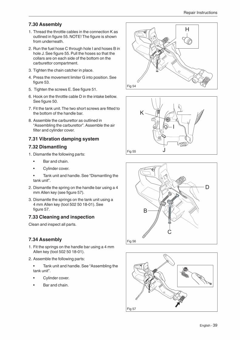
7.30 Assembly
1. Thread the throttle cables in the connection K as outlined in figure 55. NOTE! The figure is shown from underneath.
2. Run the fuel hose C through hole I and hoses B in hole J. See figure 55. Pull the hoses so that the collars are on each side of the bottom on the carburettor compartment.
3. Tighten the chain catcher in place.
4. Press the movement limiter G into position. See figure 53.
5. Tighten the screws E. See figure 51.
6. Hook on the throttle cable D in the intake bellow. See figure 50.
7. Fit the tank unit. The two short screws are fitted to the bottom of the handle bar.
8. Assemble the carburettor as outlined in “Assembling the carburettor”. Assemble the air filter and cylinder cover.
Repair Instructions
7.31 Vibration damping system
7.32 Dismantling1. Dismantle the following parts:
• Bar and chain.
• Cylinder cover.
• Tank unit and handle. See “Dismantling the tank unit”.
2. Dismantle the spring on the handle bar using a 4 mm Allen key (see figure 57).
3. Dismantle the springs on the tank unit using a 4 mm Allen key (tool 502 50 18-01). See figure 57.
7.33 Cleaning and inspectionClean and inspect all parts.
7.34 Assembly1. Fit the springs on the handle bar using a 4 mm
Allen key (tool 502 50 18-01).
2. Assemble the following parts:
• Tank unit and handle. See “Assembling the tank unit”.
• Cylinder cover.
• Bar and chain.
Fig 55
H
J
I
K
C
D
B
Fig 54
Fig 56
Fig 57
40 - English
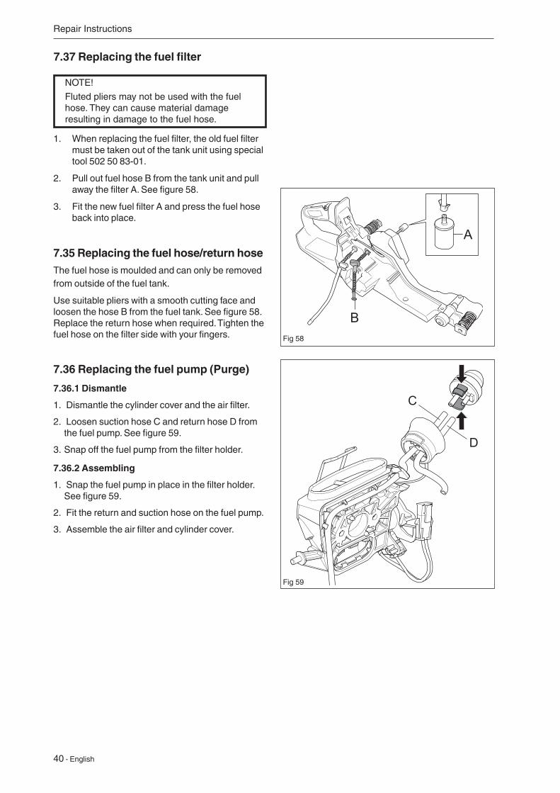
1. When replacing the fuel filter, the old fuel filter must be taken out of the tank unit using special tool 502 50 83-01.
2. Pull out fuel hose B from the tank unit and pull away the filter A. See figure 58.
3. Fit the new fuel filter A and press the fuel hose back into place.
7.35 Replacing the fuel hose/return hoseThe fuel hose is moulded and can only be removed from outside of the fuel tank.
Use suitable pliers with a smooth cutting face and loosen the hose B from the fuel tank. See figure 58. Replace the return hose when required. Tighten the fuel hose on the filter side with your fingers.
7.36 Replacing the fuel pump (Purge)
7.36.1 Dismantle
1. Dismantle the cylinder cover and the air filter.
2. Loosen suction hose C and return hose D from the fuel pump. See figure 59.
3. Snap off the fuel pump from the filter holder.
7.36.2 Assembling
1. Snap the fuel pump in place in the filter holder. See figure 59.
2. Fit the return and suction hose on the fuel pump.
3. Assemble the air filter and cylinder cover.
NOTE!
Fluted pliers may not be used with the fuel hose. They can cause material damage resulting in damage to the fuel hose.
Repair Instructions
7.37 Replacing the fuel filter
Fig 59
Fig 58
D
C
English - 41
Repair Instructions
7.38 Handle heater and carburettor heater (560XPG, 562XPG)
Certain chain saw models can be fitted with a handle heater and a carburettor heater and comprise the following:
• Generator
• Power switch
• Heating element in the rear handle
• Handle bar with heating element
• Carburettor heating element
• Thermostat
7.39 TroubleshootingIt is possible to troubleshoot with most parts fitted to the chain saw. Troubleshooting requires:
• Ammeter
• Ohmmeter
• Coolant spray
Oxidation of the connectors in the heating elements in the rear handle and the power switch’s contact plate is the most common fault.
Troubleshoot as follows:
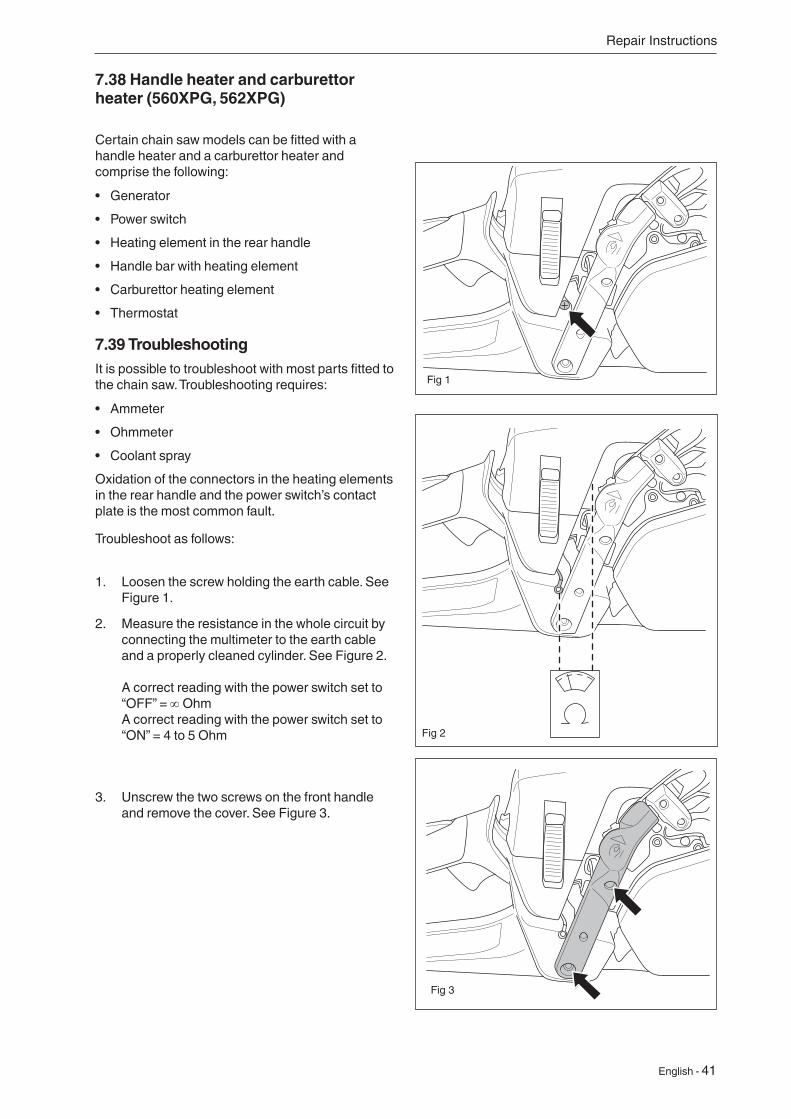
1. Loosen the screw holding the earth cable. See Figure 1.
Fig 1
Fig 3
3. Unscrew the two screws on the front handle and remove the cover. See Figure 3.
2. Measure the resistance in the whole circuit by connecting the multimeter to the earth cable and a properly cleaned cylinder. See Figure 2. A correct reading with the power switch set to “OFF” = ∞ Ohm A correct reading with the power switch set to “ON” = 4 to 5 Ohm Fig 2
42 - English
Repair Instructions
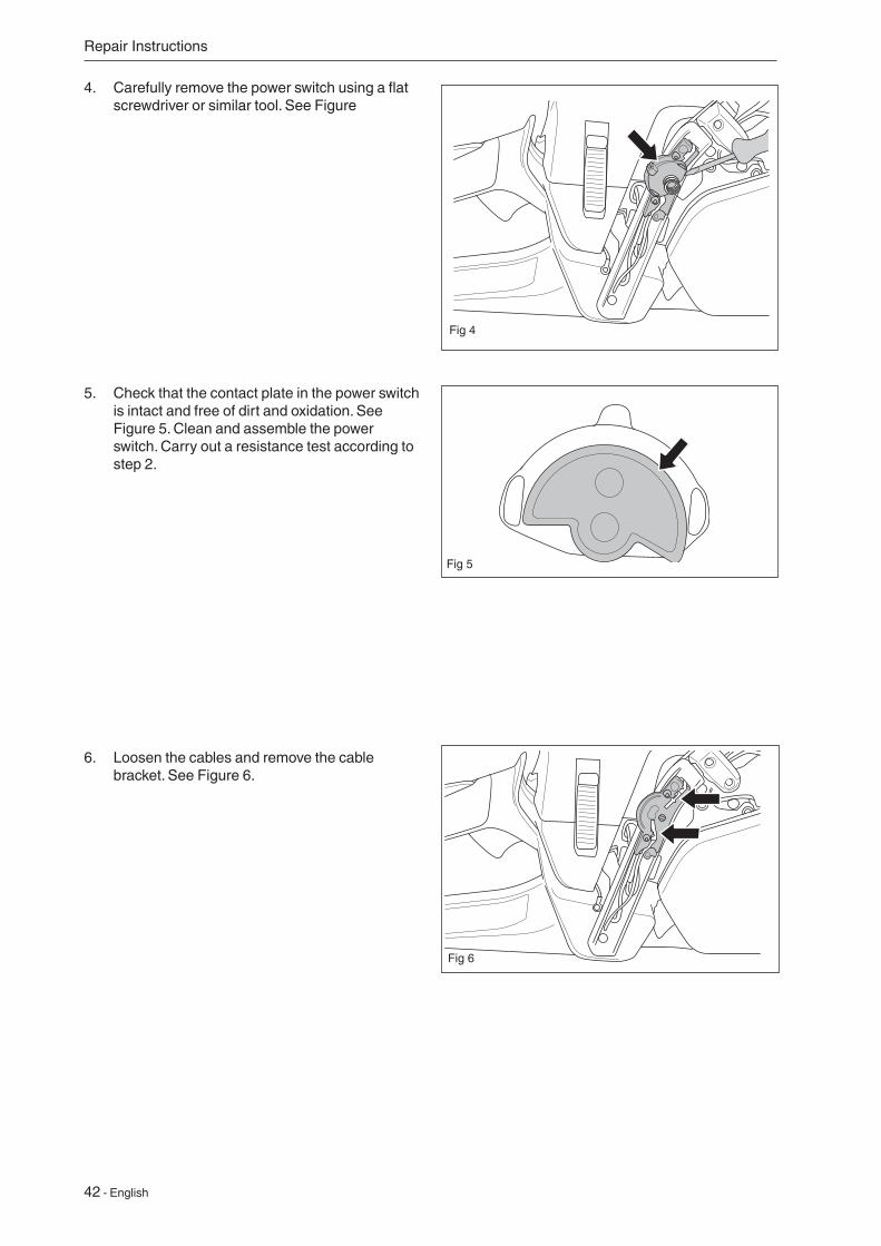
4. Carefully remove the power switch using a flat screwdriver or similar tool. See Figure
Fig 5
6. Loosen the cables and remove the cable bracket. See Figure 6.
Fig 6
5. Check that the contact plate in the power switch is intact and free of dirt and oxidation. See Figure 5. Clean and assemble the power switch. Carry out a resistance test according to step 2.
Fig 4
English - 43
Repair Instructions
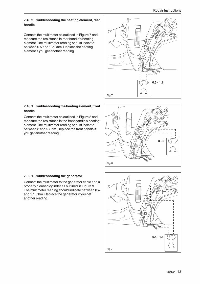
0.5 - 1.2
0.4 - 1.1
7.39.1 Troubleshooting the generator
Connect the multimeter to the generator cable and a properly cleaned cylinder as outlined in Figure 9. The multimeter reading should indicate between 0.4 and 1.1 Ohm. Replace the generator if you get another reading.
7.40.1 Troubleshooting the heating element, front handle
Connect the multimeter as outlined in Figure 8 and measure the resistance in the front handle’s heating element. The multimeter reading should indicate between 3 and 5 Ohm. Replace the front handle if you get another reading.
7.40.2 Troubleshooting the heating element, rear handle
Connect the multimeter as outlined in Figure 7 and measure the resistance in rear handle’s heating element. The multimeter reading should indicate between 0.5 and 1.2 Ohm. Replace the heating element if you get another reading.
Fig 9
Fig 8
Fig 7
3 - 5
44 - English
Repair Instructions
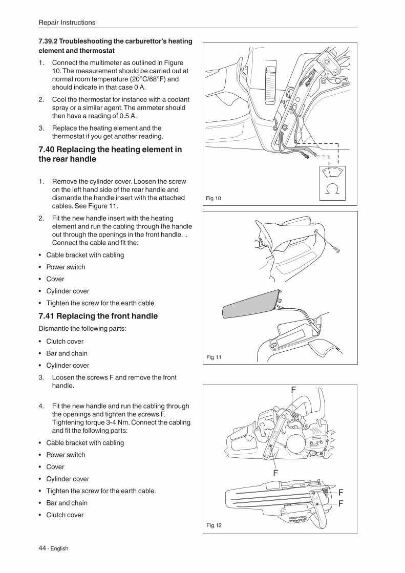
1. Remove the cylinder cover. Loosen the screw on the left hand side of the rear handle and dismantle the handle insert with the attached cables. See Figure 11.
2. Fit the new handle insert with the heating element and run the cabling through the handle out through the openings in the front handle. . Connect the cable and fit the:
• Cable bracket with cabling
• Power switch
• Cover
• Cylinder cover
• Tighten the screw for the earth cable
7.41 Replacing the front handleDismantle the following parts:
Fig 11
• Clutch cover
• Bar and chain
• Cylinder cover
3. Loosen the screws F and remove the front handle.
4. Fit the new handle and run the cabling through the openings and tighten the screws F. Tightening torque 3-4 Nm. Connect the cabling and fit the following parts:
• Cable bracket with cabling
• Power switch
• Cover
• Cylinder cover
• Tighten the screw for the earth cable.
• Bar and chain
• Clutch cover
FF
Fig 12
7.39.2 Troubleshooting the carburettor’s heating element and thermostat
1. Connect the multimeter as outlined in Figure 10. The measurement should be carried out at normal room temperature (20°C/68°F) and should indicate in that case 0 A.
2. Cool the thermostat for instance with a coolant spray or a similar agent. The ammeter should then have a reading of 0.5 A.
3. Replace the heating element and the thermostat if you get another reading.
7.40 Replacing the heating element in the rear handle
Fig 10
English - 45
Repair Instructions
F
D
7.42 Replacing the generatorDismantle the following parts:
• Clutch cover
• Bar and chain
• Cylinder cover
• Starter
• Flywheel *
* See the chapter “Dismantling the ignition module and flywheel.”
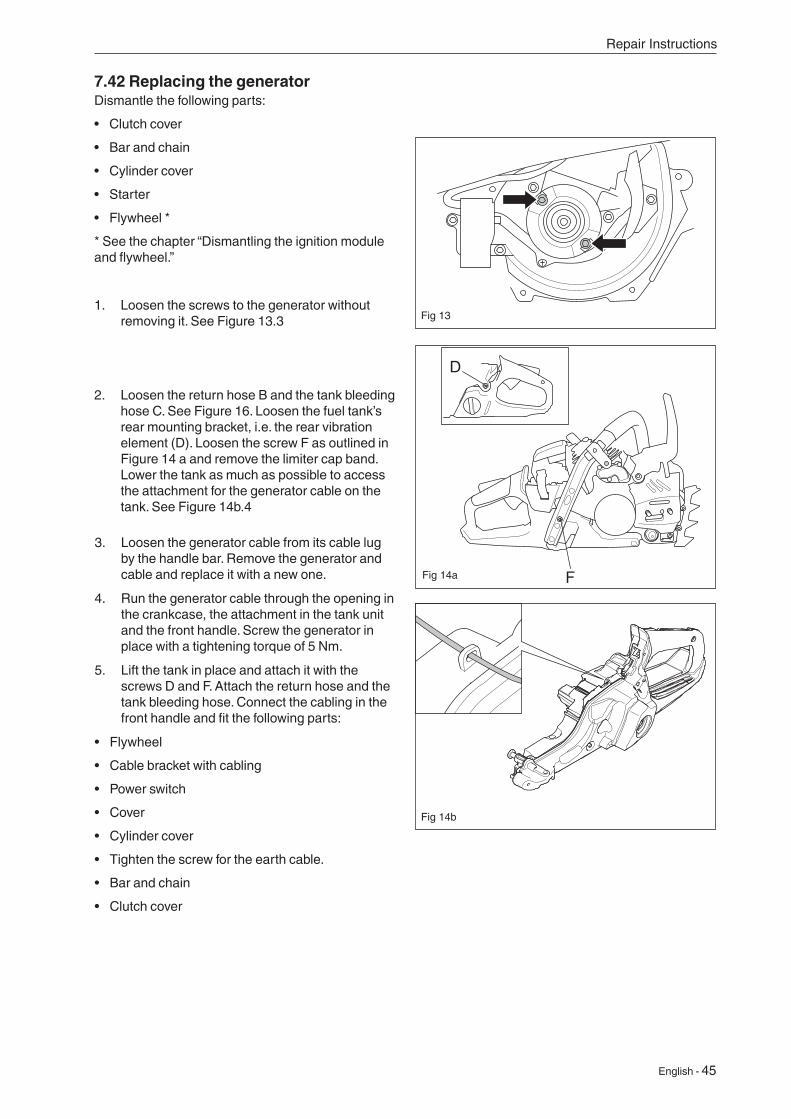
1. Loosen the screws to the generator without removing it. See Figure 13.3 Fig 13
Fig 14a
2. Loosen the return hose B and the tank bleeding hose C. See Figure 16. Loosen the fuel tank’s rear mounting bracket, i.e. the rear vibration element (D). Loosen the screw F as outlined in Figure 14 a and remove the limiter cap band. Lower the tank as much as possible to access the attachment for the generator cable on the tank. See Figure 14b.4
Fig 14b
3. Loosen the generator cable from its cable lug by the handle bar. Remove the generator and cable and replace it with a new one.
4. Run the generator cable through the opening in the crankcase, the attachment in the tank unit and the front handle. Screw the generator in place with a tightening torque of 5 Nm.
5. Lift the tank in place and attach it with the screws D and F. Attach the return hose and the tank bleeding hose. Connect the cabling in the front handle and fit the following parts:
• Flywheel
• Cable bracket with cabling
• Power switch
• Cover
• Cylinder cover
• Tighten the screw for the earth cable.
• Bar and chain
• Clutch cover
46 - English
Repair Instructions
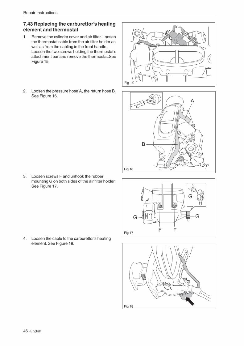
4. Loosen the cable to the carburettor’s heating element. See Figure 18.
Fig 18
2. Loosen the pressure hose A, the return hose B. See Figure 16.
Fig 16
3. Loosen screws F and unhook the rubber mounting G on both sides of the air filter holder. See Figure 17.
Fig 17
7.43 Replacing the carburettor’s heating element and thermostat1. Remove the cylinder cover and air filter. Loosen
the thermostat cable from the air filter holder as well as from the cabling in the front handle. Loosen the two screws holding the thermostat’s attachment bar and remove the thermostat.See Figure 15.
Fig 15
English - 47
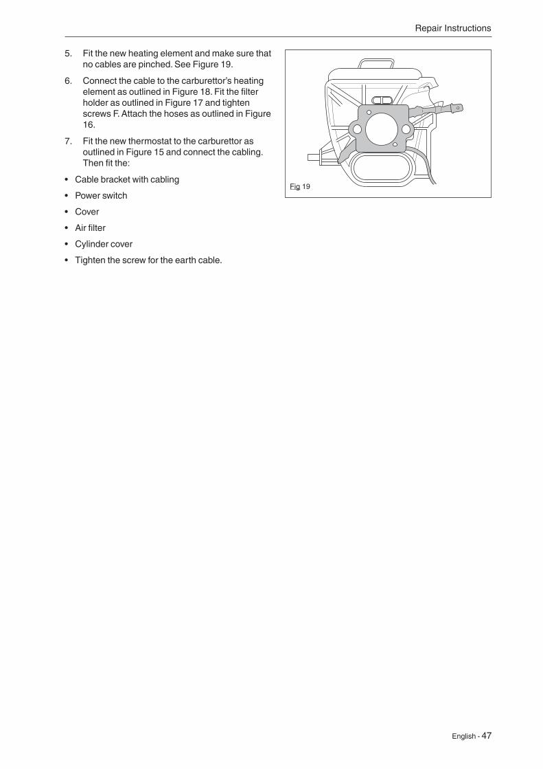
5. Fit the new heating element and make sure that no cables are pinched. See Figure 19.
6. Connect the cable to the carburettor’s heating element as outlined in Figure 18. Fit the filter holder as outlined in Figure 17 and tighten screws F. Attach the hoses as outlined in Figure 16.
7. Fit the new thermostat to the carburettor as outlined in Figure 15 and connect the cabling. Then fit the:
• Cable bracket with cabling
• Power switch
• Cover
• Air filter
• Cylinder cover
• Tighten the screw for the earth cable.
Fig 19
Repair Instructions
48 - English
Repair Instructions
7.44 Dismantling the piston and cylinder1. Dismantle:
• The cylinder cover
• The carburettor (see “Dismantling the carburettor”)
• The muffler
• The vibration element
• The spark plug cap
• The intake system
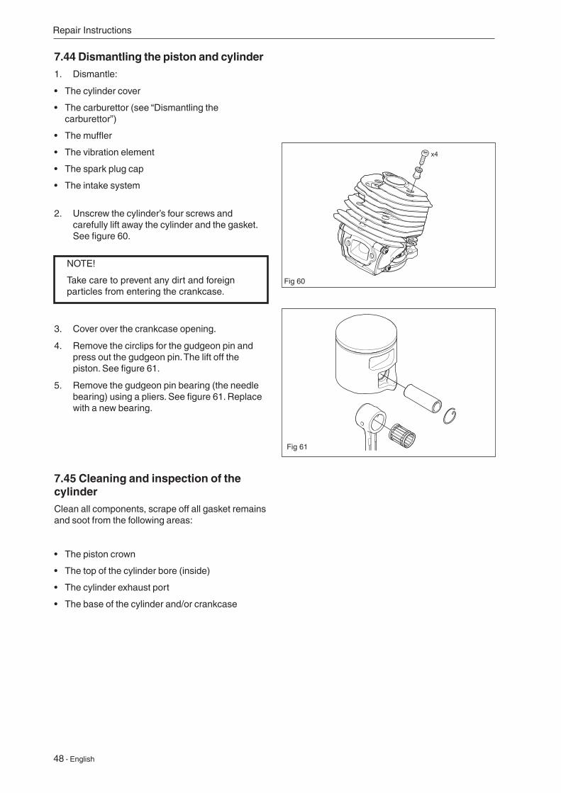
2. Unscrew the cylinder’s four screws and carefully lift away the cylinder and the gasket. See figure 60.
7.45 Cleaning and inspection of the cylinderClean all components, scrape off all gasket remains and soot from the following areas:
• The piston crown
• The top of the cylinder bore (inside)
• The cylinder exhaust port
• The base of the cylinder and/or crankcase
Fig 60
Fig 61
3. Cover over the crankcase opening.
4. Remove the circlips for the gudgeon pin and press out the gudgeon pin. The lift off the piston. See figure 61.
5. Remove the gudgeon pin bearing (the needle bearing) using a pliers. See figure 61. Replace with a new bearing.
NOTE!
Take care to prevent any dirt and foreign particles from entering the crankcase.
English - 49
Check the following:
• That the cylinder’s surface coating is not worn. Especially the upper part of the cylinder.
• That the cylinder does not have any chafe or cutting marks.
• That the piston is free of score marks. Minor scratches can be polished off using fine emery paper.
• That the piston ring is not burnt into its groove.
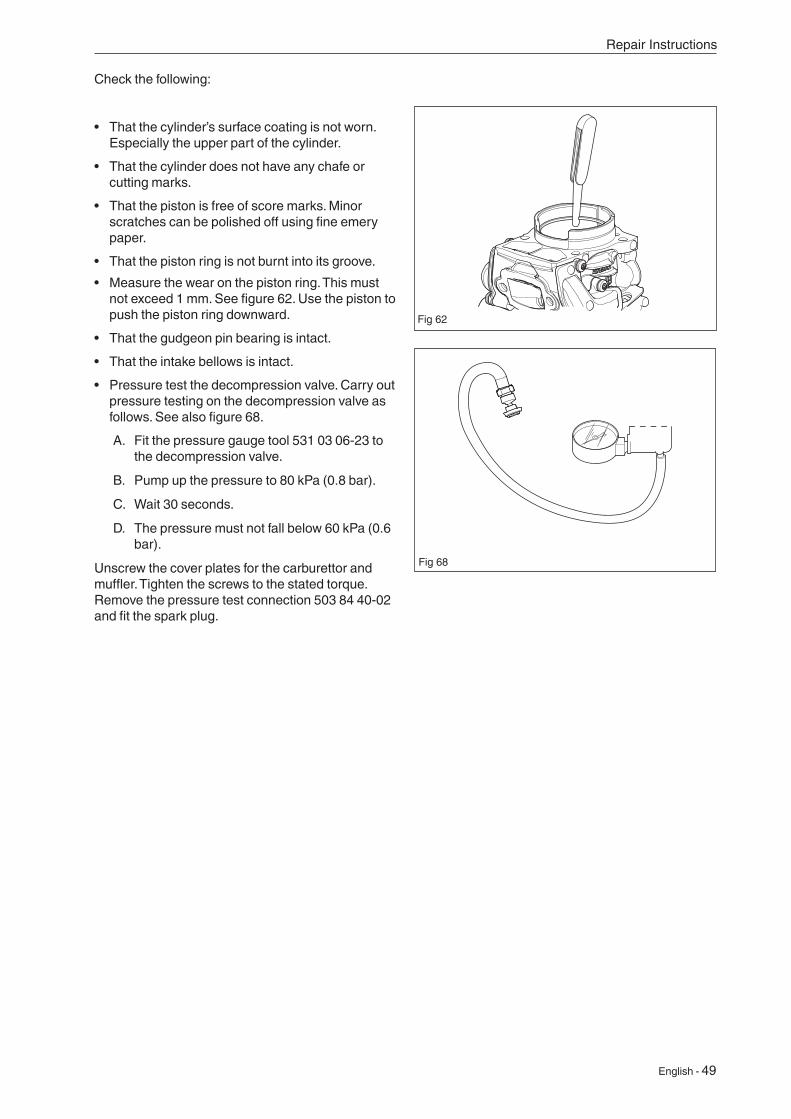
• Measure the wear on the piston ring. This must not exceed 1 mm. See figure 62. Use the piston to push the piston ring downward.
• That the gudgeon pin bearing is intact.
• That the intake bellows is intact.
• Pressure test the decompression valve. Carry out pressure testing on the decompression valve as follows. See also figure 68.
A. Fit the pressure gauge tool 531 03 06-23 to the decompression valve.
B. Pump up the pressure to 80 kPa (0.8 bar).
C. Wait 30 seconds.
D. The pressure must not fall below 60 kPa (0.6 bar).
Unscrew the cover plates for the carburettor and muffler. Tighten the screws to the stated torque. Remove the pressure test connection 503 84 40-02 and fit the spark plug.
Fig 62
Fig 68
Repair Instructions
50 - English
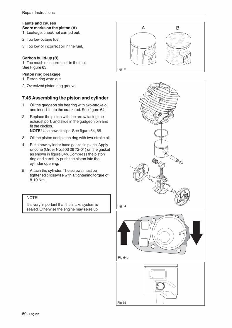
Faults and causesScore marks on the piston (A)1. Leakage, check not carried out.
2. Too low octane fuel.
3. Too low or incorrect oil in the fuel.
Carbon build-up (B)1. Too much or incorrect oil in the fuel.See Figure 63.
Piston ring breakage1. Piston ring worn out.
2. Oversized piston ring groove.
7.46 Assembling the piston and cylinder1. Oil the gudgeon pin bearing with two-stroke oil
and insert it into the crank rod. See figure 64.
2. Replace the piston with the arrow facing the exhaust port, and slide in the gudgeon pin and fit the circlips. NOTE! Use new circlips. See figure 64, 65.
3. Oil the piston and piston ring with two-stroke oil.
4. Put a new cylinder base gasket in place. Apply silicone (Order No. 503 26 72-01) on the gasket as shown in figure 64b. Compress the piston ring and carefully push the piston into the cylinder opening.
5. Attach the cylinder. The screws must be tightened crosswise with a tightening torque of 8-10 Nm.
NOTE!
It is very important that the intake system is sealed. Otherwise the engine may seize up.
Fig 63
Fig 65
Fig 64
A B
Repair Instructions
Fig 64b
English - 51
Repair Instructions
WARNING!
Once the cylinder has been pressure tested, make sure the inlet manifold is fitted correctly. Otherwise the chainsaw can be damaged.
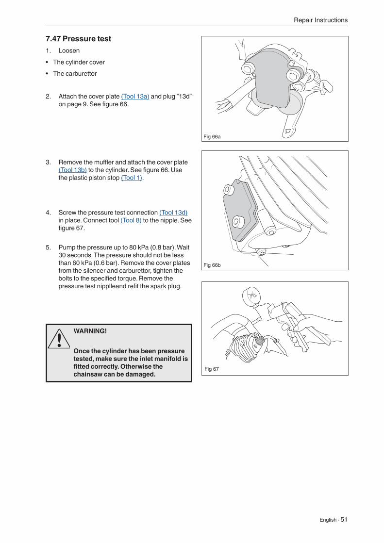
7.47 Pressure test1. Loosen
• The cylinder cover
• The carburettor
2. Attach the cover plate (Tool 13a) and plug ”13d” on page 9. See figure 66.
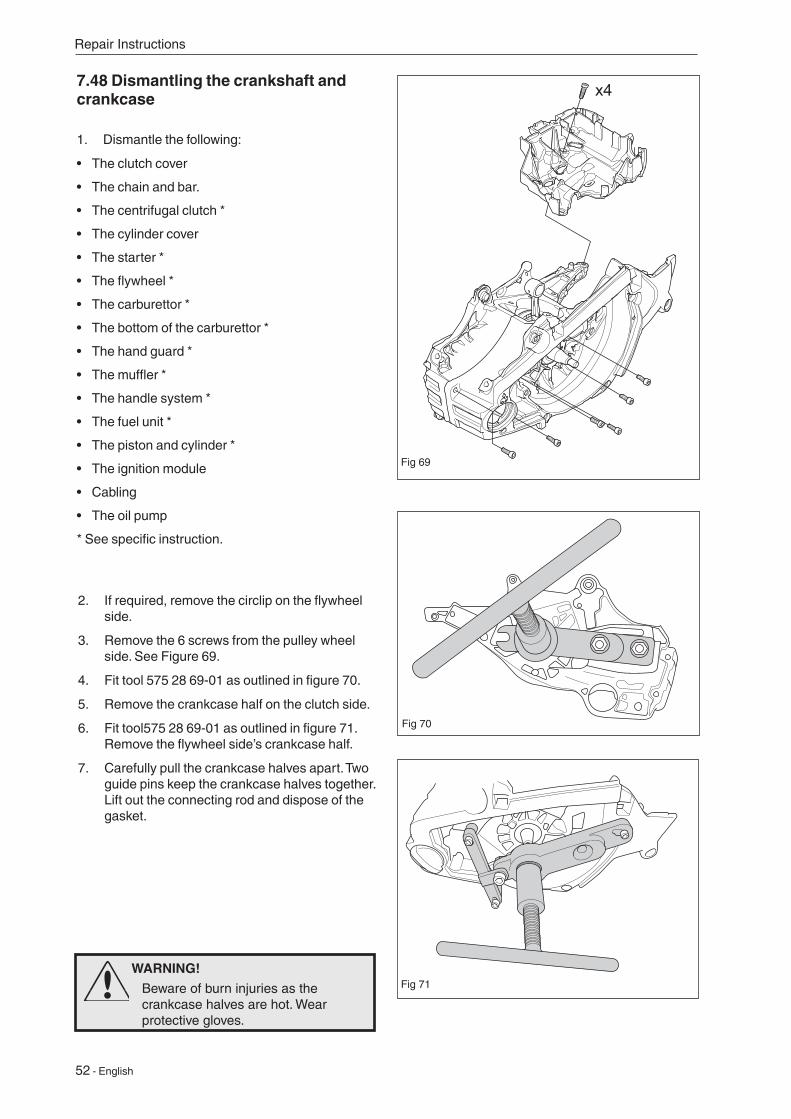
3. Remove the muffler and attach the cover plate (Tool 13b) to the cylinder. See figure 66. Use the plastic piston stop (Tool 1).
4. Screw the pressure test connection (Tool 13d) in place. Connect tool (Tool 8) to the nipple. See figure 67.
5. Pump the pressure up to 80 kPa (0.8 bar). Wait 30 seconds. The pressure should not be less than 60 kPa (0.6 bar). Remove the cover plates from the silencer and carburettor, tighten the bolts to the specified torque. Remove the pressure test nipplleand refit the spark plug.
Fig 66a
Fig 66b
Fig 67
52 - English
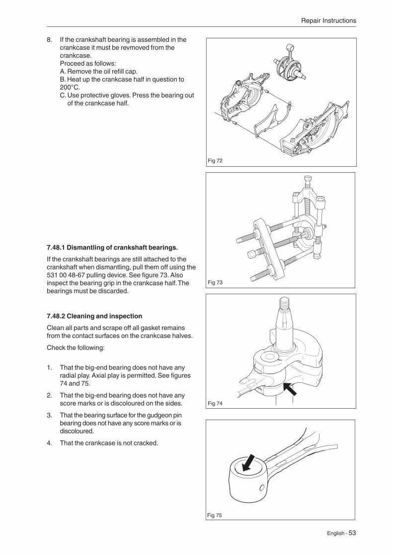
7.48 Dismantling the crankshaft and crankcase
1. Dismantle the following:
• The clutch cover
• The chain and bar.
• The centrifugal clutch *
• The cylinder cover
• The starter *
• The flywheel *
• The carburettor *
• The bottom of the carburettor *
• The hand guard *
• The muffler *
• The handle system *
• The fuel unit *
• The piston and cylinder *
• The ignition module
• Cabling
• The oil pump
* See specific instruction.
x4
Fig 69
Fig 70
Fig 71
2. If required, remove the circlip on the flywheel side.
3. Remove the 6 screws from the pulley wheel side. See Figure 69.
4. Fit tool 575 28 69-01 as outlined in figure 70.
5. Remove the crankcase half on the clutch side.
6. Fit tool575 28 69-01 as outlined in figure 71. Remove the flywheel side’s crankcase half.
7. Carefully pull the crankcase halves apart. Two guide pins keep the crankcase halves together. Lift out the connecting rod and dispose of the gasket.
Repair Instructions
WARNING!
Beware of burn injuries as the crankcase halves are hot. Wear protective gloves.
English - 53
Repair Instructions
Fig 72
Fig 73
8. If the crankshaft bearing is assembled in the crankcase it must be revmoved from the crankcase. Proceed as follows: A. Remove the oil refill cap. B. Heat up the crankcase half in question to 200°C. C. Use protective gloves. Press the bearing out
of the crankcase half.
7.48.1 Dismantling of crankshaft bearings.
If the crankshaft bearings are still attached to the crankshaft when dismantling, pull them off using the 531 00 48-67 pulling device. See figure 73. Also inspect the bearing grip in the crankcase half. The bearings must be discarded.
7.48.2 Cleaning and inspection
Clean all parts and scrape off all gasket remains from the contact surfaces on the crankcase halves.
Check the following:
1. That the big-end bearing does not have any radial play. Axial play is permitted. See figures 74 and 75.
2. That the big-end bearing does not have any score marks or is discoloured on the sides.
3. That the bearing surface for the gudgeon pin bearing does not have any score marks or is discoloured.
4. That the crankcase is not cracked.
Fig 74
Fig 75
54 - English
Fig 76
Fig 77
Fig 78
x4
7.48.3 Assembly of crankshaft bearings
1. New bearings must be used. Proceed as follows:
A. Heat up the crankcase half in question to 200°C.
B. Use protective gloves. When fitting the bearing in the crunkcase half the bearing must be fitted to the stop in the crankcase.
C. Allow the crankcase half to cool down before continuing with the work.
Fig 79
Repair Instructions
D. Fit the oil refill cap.
NOTE!
Make sure the connecting rod is not crushed against the crankcase when the crankcase and crankshaft are fitted together.
7.49 Assembly of crankshaft and crankcase1. Use the 502 50 30-23 tool. Use the back end of
the sleeve and slot the crankshaft in place into the clutch side of the crankcase half. See figure 76. Tighten until the crankshaft collar comes into contact with the bearing.
2. Insert the guide pin in the crankcase half on the clutch side, apply grease and fit the gasket(C). See figure 77.
3. Use the 502 50 30-23 tool. Turn the sleeve and slot the crankcase half in place on the flywheel side. Tighten until the gasket is pinned in place between the crankcase halves. See figure 78.
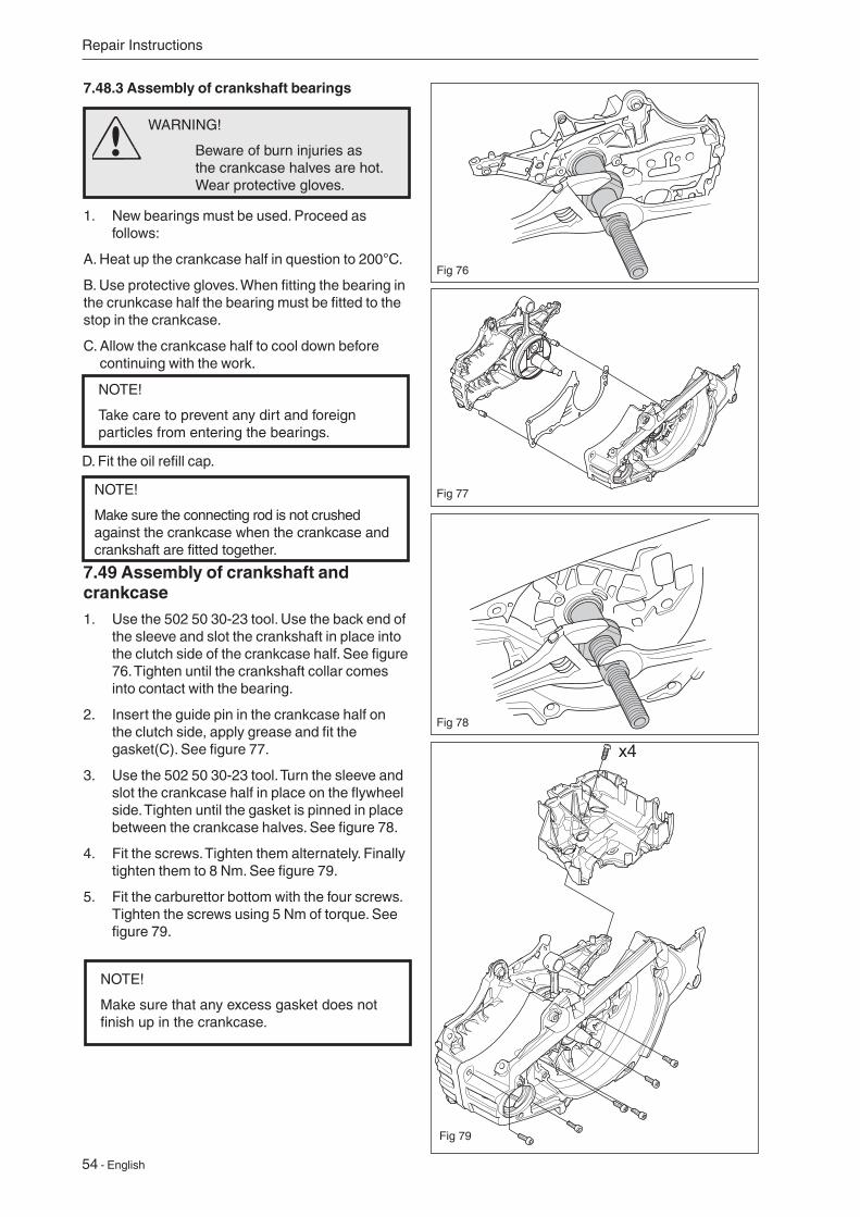
4. Fit the screws. Tighten them alternately. Finally tighten them to 8 Nm. See figure 79.
5. Fit the carburettor bottom with the four screws. Tighten the screws using 5 Nm of torque. See figure 79.
NOTE!
Make sure that any excess gasket does not finish up in the crankcase.
NOTE!
Take care to prevent any dirt and foreign particles from entering the bearings.
WARNING!
Beware of burn injuries as the crankcase halves are hot. Wear protective gloves.
English - 55
Repair Instructions
Fig 80
Fig 81
6. Assemble the following parts:
A. Tank unit.
B. Piston and cylinder.
C. Muffler.
D. Carburettor.
E. Centrifugal clutch.
F. Electrical System.
G. Starter.
H. Bar and chain. See the Operator’s Manual.
7.50 Assembly of sealing rings
1. To replace the crankshaft’s sealing rings, first dismantle the following parts:
On the flywheel side:
• Starter.
• Flywheel.
On the clutch side:
• Bar and chain.
• Chain guide plate.
• Centrifugal clutch.
• Oil pump.
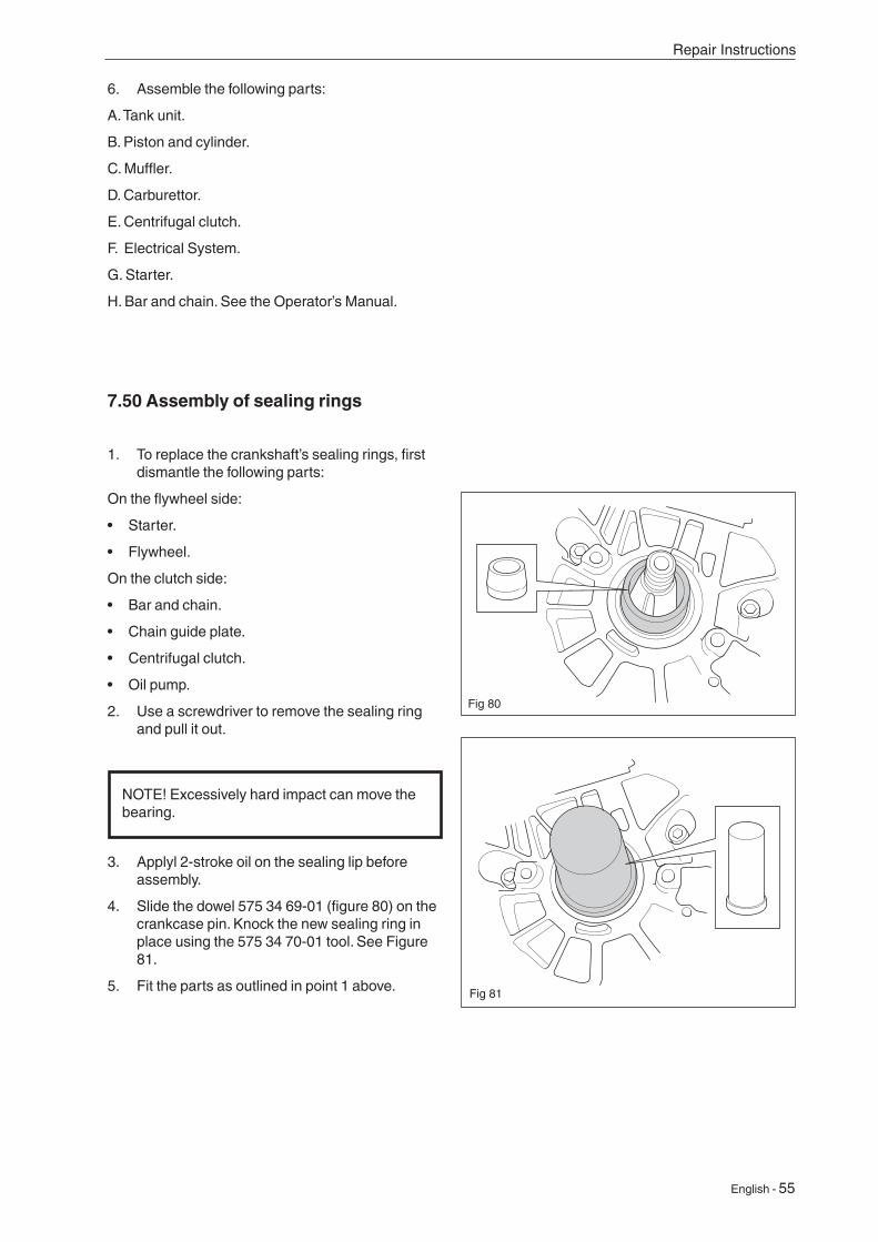
2. Use a screwdriver to remove the sealing ring and pull it out.
3. Applyl 2-stroke oil on the sealing lip before assembly.
4. Slide the dowel 575 34 69-01 (figure 80) on the crankcase pin. Knock the new sealing ring in place using the 575 34 70-01 tool. See Figure 81.
5. Fit the parts as outlined in point 1 above.
NOTE! Excessively hard impact can move the bearing.
56 - English
7.51 AssemblingFit the following parts:
• The piston and cylinder *
• The fuel unit *
• The handle system *
• The muffler *
• The hand guard *
• The bottom of the carburettor *
• The carburettor *
• The flywheel *
• The starter *
• The cylinder cover
• The centrifugal clutch *
• The chain and bar.
• The clutch cover
* See specific instruction.
Repair Instructions
7.52 Replacing the bar bolt
7.52.1 Replacing a bar bolt with intact crankcase
1. Empty the oil tank.
2. Knock in the old bar bolts from the outside so that they end up in the oil tank.
3. Remove the bolts from the oil tank.
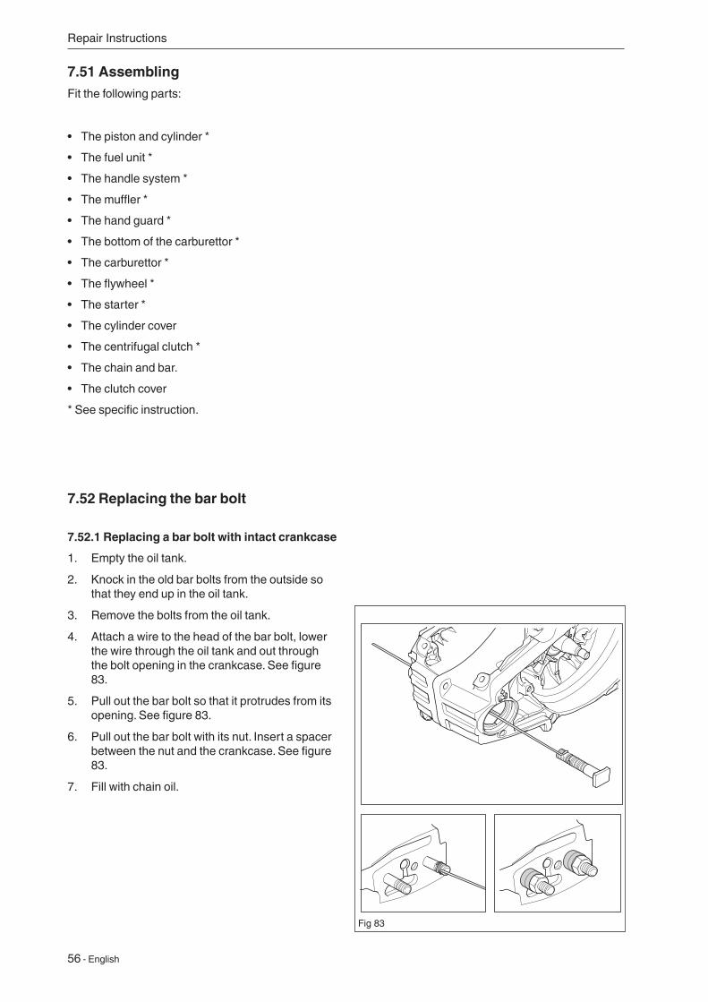
4. Attach a wire to the head of the bar bolt, lower the wire through the oil tank and out through the bolt opening in the crankcase. See figure 83.
5. Pull out the bar bolt so that it protrudes from its opening. See figure 83.
6. Pull out the bar bolt with its nut. Insert a spacer between the nut and the crankcase. See figure 83.
7. Fill with chain oil.
Fig 83
English - 57
Repair Instructions
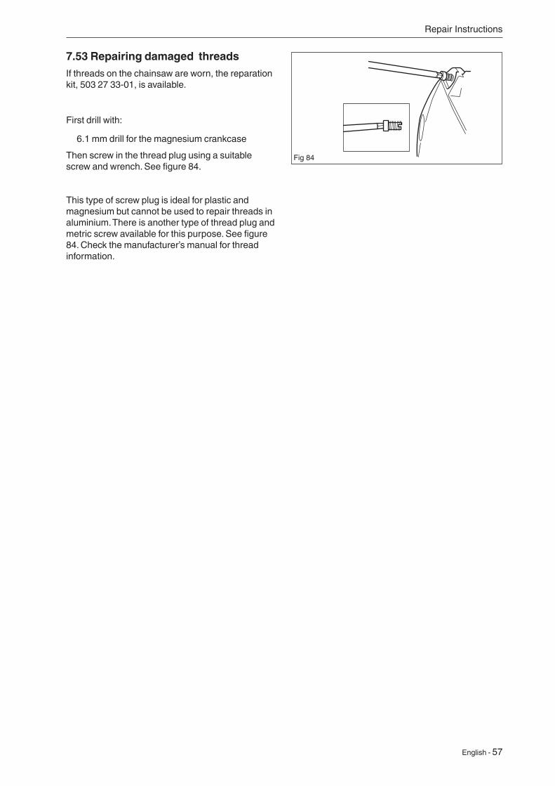
7.53 Repairing damaged threads If threads on the chainsaw are worn, the reparation kit, 503 27 33-01, is available.
First drill with:
6.1 mm drill for the magnesium crankcase
Then screw in the thread plug using a suitable screw and wrench. See figure 84.
This type of screw plug is ideal for plastic and magnesium but cannot be used to repair threads in aluminium. There is another type of thread plug and metric screw available for this purpose. See figure 84. Check the manufacturer’s manual for thread information.
Fig 84

English - 58
Troubleshooting
Starting
Idling (low speed)
Idling (low speed) (continued)
Leaking inlet hose (rubber)Loose carburettor mountingLoose or faulty fuel pipeBlocked fuel filterBlocked fuel lineTank ventilator blockedThe throttle valve shaft is inertThrottle stay is bindingDefective throttle return springBent valve axle stopFaulty diffuser jet
Worn needle/needle tip
Worn lever arm in the control systemLeaking diaphragm/cover plate
Does not idle
Too rich idling
8 TroubleshootingThe different faults which may occur on the chain saw are divided into four groups. Within each group possible operating faults are listed to the left while the probable fault alternatives are listed to the right. The most likely fault is listed first, etc. See separate instruction for Autotune troubleshooting.
Worn needle/needle tip
Leaking diaphragm/cover plate
Worn lever arm in the control system
Faulty diffuser jet
Blocked fuel filter
Blocked fuel line
Leaking inlet hose (rubber)
Loose carburettor mounting
Worn throttle valve axle
Loose throttle valve screw
Worn throttle valve
Leaking control system (air or fuel)
The control system’s centre knob is worn
Hole in diaphragm
Leaking diaphragm/ cover plate
Leaking crankcase
Blocked fuel line
Leaking control system (air or fuel)
Leaking diaphragm/cover plate
Faulty diffuser jet
Leaking crankcase
Worn needle/needle tip
Leaking diaphragm/ cover plate
Difficult to start
The carburettor leaks fuel
Floods when the engine is not running
Air filter blockedChoke does not workWorn choke axleWorn choke valveBlocked fuel filterBlocked fuel linePiston ring is stuckBlocked impulse channel
Loose or faulty fuel pipeHole in diaphragmWorn needle/needle tipControl system stickingControl system set too highLeaking control system (air or fuel)The cover on the carburettorpump side is loose
Worn needle/needle tipControl system set too highControl system sticking
Uneven idling
Too much fuel at idle speed
59 - English
Troubleshooting
Acceleration and retardation
Does not accelerate
The engine stops when releasing the throttle
Blocked air filterTank venting cloggedBlocked fuel filterBlocked fuel lineLoose or faulty fuel pipeBlocked impulse channelThe cover on the carburettor pump side is looseFaulty pump diaphragmLeaking inlet hose (rubber)Loose carburettor mountingControl system set too lowControl system incorrectly assembledControl system stickingFaulty diffuser jetBlocked muffler
Faulty pump diaphragmControl system set too highControl system stickingFaulty diffuser jet
Blocked air filterFaulty pump diaphragmFaulty diffuser jet
8.1 Troubleshooting methodsIn addition to faults given in the above schematic, troubleshooting can be carried out on a specific component or specific chain saw system. The different procedures are described in respective sections and are as follows:
• Function check of chain brake
• Resistance testing the stop plate
• Pressure testing the carburettor
• Pressure testing the decompression valve
• Pressure testing the cylinder
High speed
Will not run at full throttle
Low power
Will not “four stroke”
Blocked air filterTank venting cloggedBlocked fuel filterBlocked fuel lineLoose or faulty fuel pipeImpulse channel leakingBlocked impulse channelThe cover on the carburettor pump side is looseFaulty pump diaphragmLeaking inlet hose (rubber)Loose carburettor mountingControl system set too lowDamaged control systemControl system incorrectly assembledLeaking diaphragm/cover plateControl system stickingBlocked muffler
Tank venting cloggedBlocked fuel filterImpulse channel leakingBlocked impulse channelThe cover on the carburettor pump side is looseFaulty pump diaphragmBlocked air filterControl system stickingLeaking control system (air or fuel)Control system incorrectly assembledLoose diaphragmHole in diaphragmLeaking diaphragm/cover plate
Tank venting cloggedBlocked fuel filterBlocked fuel lineLoose or faulty fuel pipeImpulse channel leakingBlocked impulse channelThe cover on the carburettor pump side is looseFaulty pump diaphragmLeaking inlet hose (rubber)Loose carburettor mountingControl system set too low
Leaking control system (air or fuel)
Control system incorrectly assembledLoose diaphragmHole in diaphragmLeaking diaphragm/cover plate

2018W50• 115 26 56-26


