World Housing Encyclopedia Report Country: Iran Housing Type: Steel frame with semi-rigid "Khorjini" connections and jack arch roof "Taagh-e-Zarbi". Contributors: Arzhang Alimoradi Primary Reviewer: Farzad Naeim Created on: 6/5/2002 Last Modified: 7/2/2003 This encyclopedia contains information contributed by various earthquake engineering professionals around the world. All opinions, findings, conclusions, and recommendations expressed herein are those of the various participants, and do not necessarily reflect the views of the Earthquake Engineering Research Institute, the International Association for Earthquake Engineering, the Engineering Information Foundation, John A. Martin & Associates, Inc. or the participants' organizations.
Transcript
World Housing Encyclopedia Report
Country: Iran
Housing Type: Steel frame with semi-rigid "Khorjini" connections and jack arch roof"Taagh-e-Zarbi".
Contributors:Arzhang Alimoradi
Primary Reviewer:Farzad Naeim
Created on: 6/5/2002Last Modified: 7/2/2003
This encyclopedia contains information contributed by various earthquake engineering professionalsaround the world. All opinions, findings, conclusions, and recommendations expressed herein are those
of the various participants, and do not necessarily reflect the views of the Earthquake EngineeringResearch Institute, the International Association for Earthquake Engineering, the Engineering Information
Foundation, John A. Martin & Associates, Inc. or the participants' organizations.
Table of Contents
General Information............................................................................................1Architectural Features........................................................................................ 3Socio-Economic Issues...................................................................................... 4Structural Features............................................................................................. 5Evaluation of Seismic Performance and Seismic Vulnerability.......................... 9Earthquake Damage Patterns............................................................................ 11Building Materials and Construction Process..................................................... 12Construction Economics.....................................................................................14Insurance............................................................................................................15Seismic Strengthening Technologies................................................................. 16References......................................................................................................... 17Contributors........................................................................................................ 18Figures................................................................................................................19
1 General Information
1.1 CountryIran
1.3 Housing TypeSteel frame with semi-rigid "Khorjini"connections and jack arch roof "Taagh-e-Zarbi".
1.4 SummaryThis is a common type of urban/ruralconstruction in many parts of Iran. It is widelyused in the cities as a popular structural systemfor low-rise residential buildings because of easeof construction and erection of the frames.Buildings of this type are up to 5 stories high,with height/width aspect ratio on the order of 1.5.This system consists of a special kind of steelframing with heavy brick infills as partitions. Roofgirders are connected to the supporting columnsby means of semi-rigid connections.Diaphragms may range from flexible to rigiddepending on the detailing and the constructionquality. The structure is extremely heavybecause of the brick infills between the roofbeams. Roof is constructed in the form of ashallow arch called jack arch. Roofs, ceilings,and floors constructed in this way contributed tobuilding failures and to an unusually high deathtoll in many recent earthquakes in Iran. As manyas half the buildings completed in the early1970s in Iran had jack arches. In a jack archsystem, steel beams or a reinforced concretejoist system span the distance between the maingirders across the length of the building. An archmade of small bricks connect the beams. Eacharch has a rise of only about ten centimeters.The "valleys" of this wave-like surface are filledwith mortar. The completed ceiling, roof, or flooris thick and heavy. Frequently the steel supportbeams are not tied together properly or are leftuntied (From:http://www.johnmartin.com/eqshow/647014_00.htm).Seismic vulnerability of this system is observedas medium to high. The dynamic behavior of thesystem in the two main perpendicular directionsof the building plan differs significantly becauseof the differences in the stiffness andconfiguration of the connections in these twodirections. Furthermore, "X" bracings are usuallyused in the weak direction which furthermagnifies the non-uniform behavior of thestructural system.
FIGURE 1A: Typical Building
Page 1
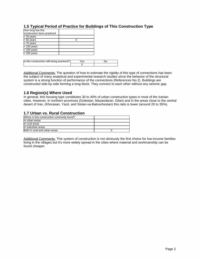
1.5 Typical Period of Practice for Buildings of This Construction TypeHow long has thisconstruction been practiced< 25 years< 50 years X< 75 years< 100 years< 200 years> 200 years
Is this construction still being practiced? Yes NoX
Additional Comments: The question of how to estimate the rigidity of this type of connections has beenthe subject of many analytical and experimental research studies since the behavior of the structuralsystem is a strong function of performance of the connections (References No.2). Buildings areconstructed side-by-side forming a long block. They connect to each other without any seismic gap.
1.6 Region(s) Where UsedIn general, this housing type constitutes 30 to 40% of urban construction types in most of the Iraniancities. However, in northern provinces (Golestan, Mazandaran, Gilan) and in the areas close to the centraldesert of Iran, (Khorasan, Yazd, and Sistan-va-Baloochestan) this ratio is lower (around 20 to 35%).
1.7 Urban vs. Rural ConstructionWhere is this construction commonly found?In urban areasIn rural areasIn suburban areasBoth in rural and urban areas X
Additional Comments: This system of construction is not obviously the first choice for low-income familiesliving in the villages but it's more widely spread in the cities where material and workmanship can befound cheaper.
Page 2
2 Architectural Features
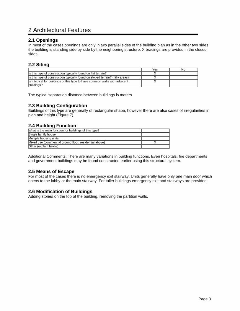
2.1 OpeningsIn most of the cases openings are only in two parallel sides of the building plan as in the other two sidesthe building is standing side by side by the neighboring structure. X bracings are provided in the closedsides.
2.2 SitingYes No
Is this type of construction typically found on flat terrain? XIs this type of construction typically found on sloped terrain? (hilly areas) XIs it typical for buildings of this type to have common walls with adjacentbuildings?
X
The typical separation distance between buildings is meters
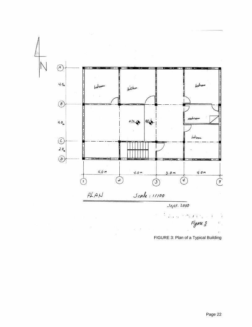
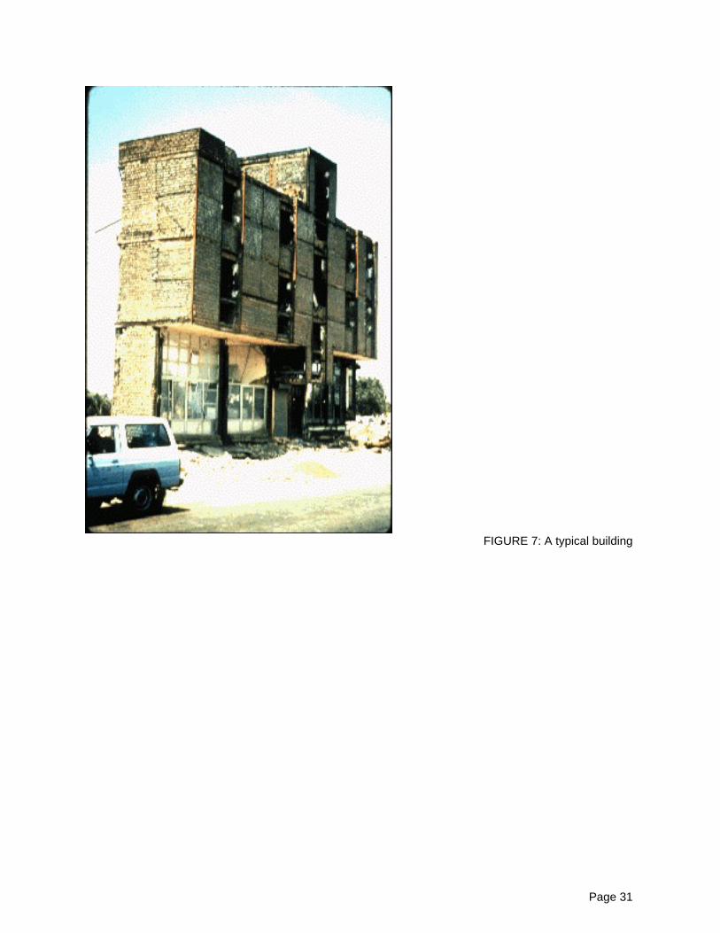
2.3 Building ConfigurationBuildings of this type are generally of rectangular shape, however there are also cases of irregularities inplan and height (Figure 7).
2.4 Building FunctionWhat is the main function for buildings of this type?Single family houseMultiple housing unitsMixed use (commercial ground floor, residential above) XOther (explain below)
Additional Comments: There are many variations in building functions. Even hospitals, fire departmentsand government buildings may be found constructed earlier using this structural system.
2.5 Means of EscapeFor most of the cases there is no emergency exit stairway. Units generally have only one main door whichopens to the lobby or the main stairway. For taller buildings emergency exit and stairways are provided.
2.6 Modification of BuildingsAdding stories on the top of the building, removing the partition walls.
Page 3
3 Socio-Economic Issues
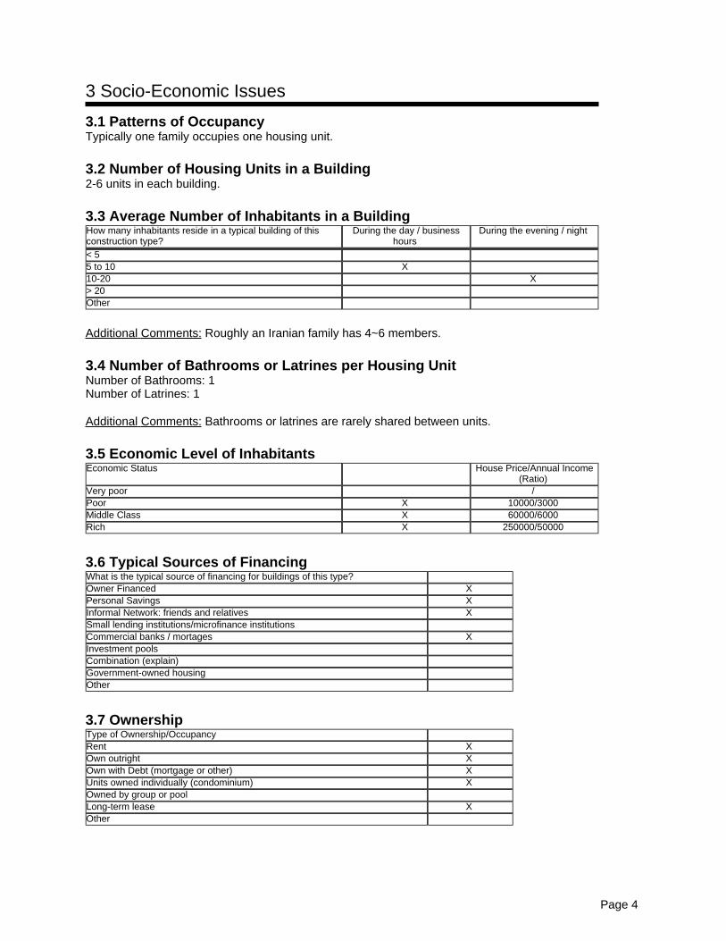
3.1 Patterns of OccupancyTypically one family occupies one housing unit.
3.2 Number of Housing Units in a Building2-6 units in each building.
3.3 Average Number of Inhabitants in a BuildingHow many inhabitants reside in a typical building of thisconstruction type?
During the day / businesshours
During the evening / night
< 55 to 10 X10-20 X> 20Other
Additional Comments: Roughly an Iranian family has 4~6 members.
3.4 Number of Bathrooms or Latrines per Housing UnitNumber of Bathrooms: 1Number of Latrines: 1
Additional Comments: Bathrooms or latrines are rarely shared between units.
3.5 Economic Level of InhabitantsEconomic Status House Price/Annual Income
(Ratio)Very poor /Poor X 10000/3000Middle Class X 60000/6000Rich X 250000/50000
3.6 Typical Sources of FinancingWhat is the typical source of financing for buildings of this type?Owner Financed XPersonal Savings XInformal Network: friends and relatives XSmall lending institutions/microfinance institutionsCommercial banks / mortages XInvestment poolsCombination (explain)Government-owned housingOther
3.7 OwnershipType of Ownership/OccupancyRent XOwn outright XOwn with Debt (mortgage or other) XUnits owned individually (condominium) XOwned by group or poolLong-term lease XOther
Page 4
4 Structural Features
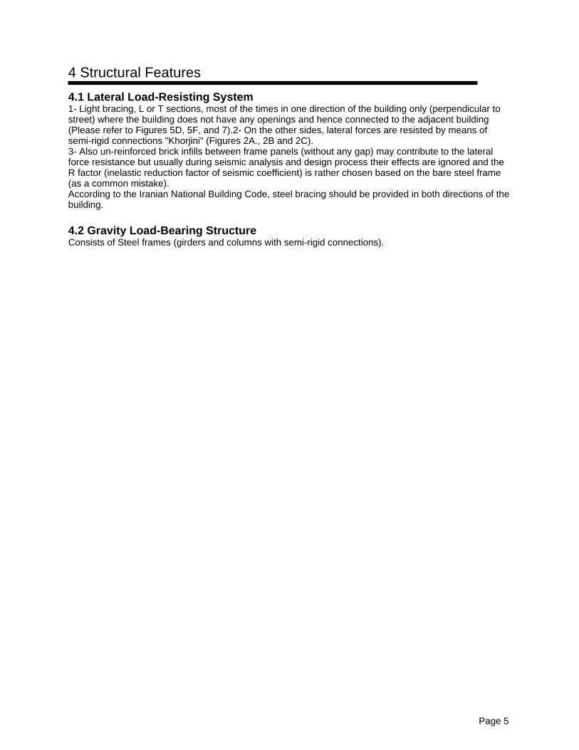
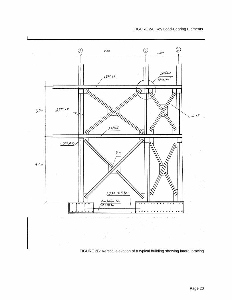
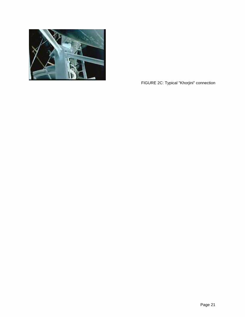
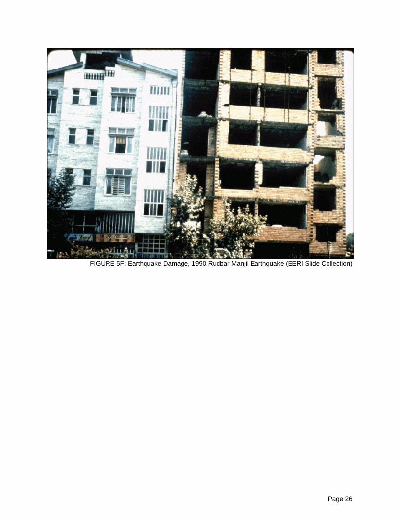
4.1 Lateral Load-Resisting System1- Light bracing, L or T sections, most of the times in one direction of the building only (perpendicular tostreet) where the building does not have any openings and hence connected to the adjacent building(Please refer to Figures 5D, 5F, and 7).2- On the other sides, lateral forces are resisted by means ofsemi-rigid connections "Khorjini" (Figures 2A., 2B and 2C).3- Also un-reinforced brick infills between frame panels (without any gap) may contribute to the lateralforce resistance but usually during seismic analysis and design process their effects are ignored and theR factor (inelastic reduction factor of seismic coefficient) is rather chosen based on the bare steel frame(as a common mistake).According to the Iranian National Building Code, steel bracing should be provided in both directions of thebuilding.
4.2 Gravity Load-Bearing StructureConsists of Steel frames (girders and columns with semi-rigid connections).
Page 5
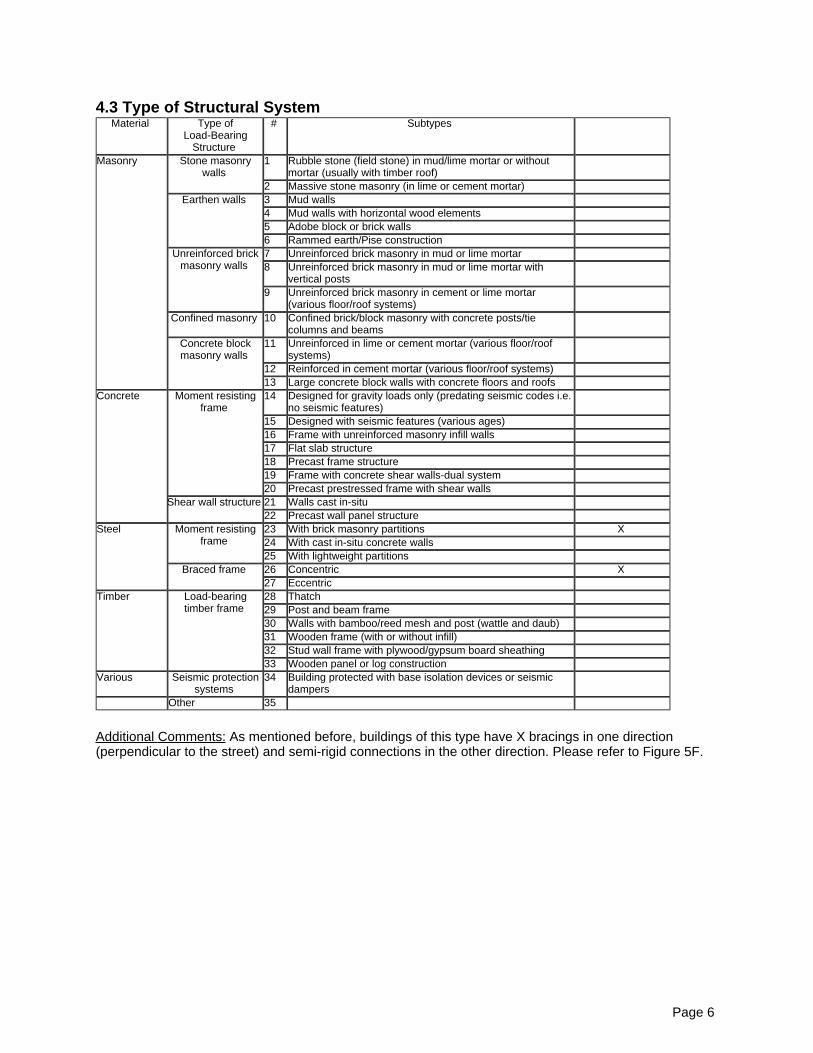
4.3 Type of Structural SystemMaterial Type of
Load-BearingStructure
# Subtypes
Masonry Stone masonrywalls
1 Rubble stone (field stone) in mud/lime mortar or withoutmortar (usually with timber roof)
2 Massive stone masonry (in lime or cement mortar)Earthen walls 3 Mud walls
4 Mud walls with horizontal wood elements5 Adobe block or brick walls6 Rammed earth/Pise construction
Unreinforced brickmasonry walls
7 Unreinforced brick masonry in mud or lime mortar8 Unreinforced brick masonry in mud or lime mortar with
vertical posts9 Unreinforced brick masonry in cement or lime mortar
23 With brick masonry partitions X24 With cast in-situ concrete walls25 With lightweight partitions
Braced frame 26 Concentric X27 Eccentric
Timber Load-bearingtimber frame
28 Thatch29 Post and beam frame30 Walls with bamboo/reed mesh and post (wattle and daub)31 Wooden frame (with or without infill)32 Stud wall frame with plywood/gypsum board sheathing33 Wooden panel or log construction
Various Seismic protectionsystems
34 Building protected with base isolation devices or seismicdampers
Other 35
Additional Comments: As mentioned before, buildings of this type have X bracings in one direction(perpendicular to the street) and semi-rigid connections in the other direction. Please refer to Figure 5F.
Page 6
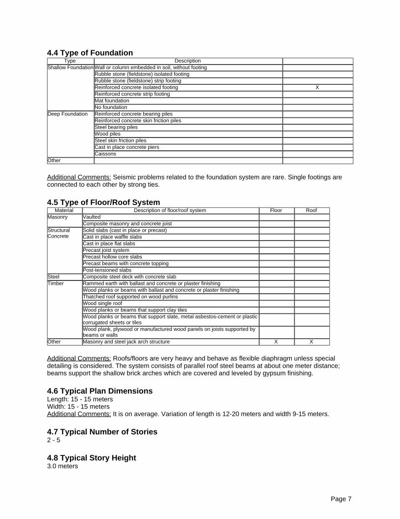
4.4 Type of FoundationType Description
Shallow Foundation Wall or column embedded in soil, without footingRubble stone (fieldstone) isolated footingRubble stone (fieldstone) strip footingReinforced concrete isolated footing XReinforced concrete strip footingMat foundationNo foundation
Deep Foundation Reinforced concrete bearing pilesReinforced concrete skin friction pilesSteel bearing pilesWood pilesSteel skin friction pilesCast in place concrete piersCaissons
Other
Additional Comments: Seismic problems related to the foundation system are rare. Single footings areconnected to each other by strong ties.
4.5 Type of Floor/Roof SystemMaterial Description of floor/roof system Floor Roof
Masonry VaultedComposite masonry and concrete joist
StructuralConcrete
Solid slabs (cast in place or precast)Cast in place waffle slabsCast in place flat slabsPrecast joist systemPrecast hollow core slabsPrecast beams with concrete toppingPost-tensioned slabs
Steel Composite steel deck with concrete slabTimber Rammed earth with ballast and concrete or plaster finishing
Wood planks or beams with ballast and concrete or plaster finishingThatched roof supported on wood purlinsWood single roofWood planks or beams that support clay tilesWood planks or beams that support slate, metal asbestos-cement or plasticcorrugated sheets or tilesWood plank, plywood or manufactured wood panels on joists supported bybeams or walls
Other Masonry and steel jack arch structure X X
Additional Comments: Roofs/floors are very heavy and behave as flexible diaphragm unless specialdetailing is considered. The system consists of parallel roof steel beams at about one meter distance;beams support the shallow brick arches which are covered and leveled by gypsum finishing.
4.6 Typical Plan DimensionsLength: 15 - 15 metersWidth: 15 - 15 metersAdditional Comments: It is on average. Variation of length is 12-20 meters and width 9-15 meters.
4.7 Typical Number of Stories2 - 5
4.8 Typical Story Height3.0 meters
Page 7
Additional Comments: First floor usually has higher height, in the rage of about 4.0 m, for commercial use.
4.9 Typical Span4 meters
Additional Comments: Variation of span is 3-5 meters.
4.10 Typical Wall Density4%
4.11 General Applicability of Answers to Questions in Section 4Please refer to the figures and drawings.
Page 8
5 Evaluation of Seismic Performance and Seismic Vulnerability
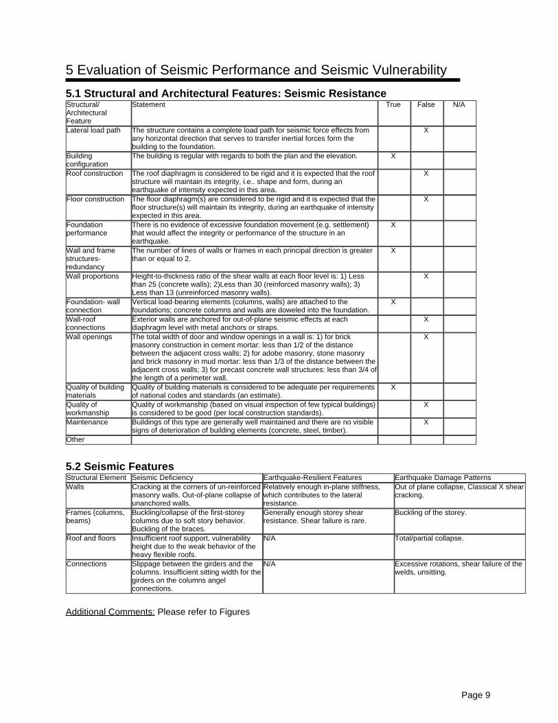
5.1 Structural and Architectural Features: Seismic ResistanceStructural/ArchitecturalFeature
Statement True False N/A
Lateral load path The structure contains a complete load path for seismic force effects fromany horizontal direction that serves to transfer inertial forces form thebuilding to the foundation.
X
Buildingconfiguration
The building is regular with regards to both the plan and the elevation. X
Roof construction The roof diaphragm is considered to be rigid and it is expected that the roofstructure will maintain its integrity, i.e.. shape and form, during anearthquake of intensity expected in this area.
X
Floor construction The floor diaphragm(s) are considered to be rigid and it is expected that thefloor structure(s) will maintain its integrity, during an earthquake of intensityexpected in this area.
X
Foundationperformance
There is no evidence of excessive foundation movement (e.g. settlement)that would affect the integrity or performance of the structure in anearthquake.
X
Wall and framestructures-redundancy
The number of lines of walls or frames in each principal direction is greaterthan or equal to 2.
X
Wall proportions Height-to-thickness ratio of the shear walls at each floor level is: 1) Lessthan 25 (concrete walls); 2)Less than 30 (reinforced masonry walls); 3)Less than 13 (unreinforced masonry walls).
X
Foundation- wallconnection
Vertical load-bearing elements (columns, walls) are attached to thefoundations; concrete columns and walls are doweled into the foundation.
X
Wall-roofconnections
Exterior walls are anchored for out-of-plane seismic effects at eachdiaphragm level with metal anchors or straps.
X
Wall openings The total width of door and window openings in a wall is: 1) for brickmasonry construction in cement mortar: less than 1/2 of the distancebetween the adjacent cross walls; 2) for adobe masonry, stone masonryand brick masonry in mud mortar: less than 1/3 of the distance between theadjacent cross walls; 3) for precast concrete wall structures: less than 3/4 ofthe length of a perimeter wall.
X
Quality of buildingmaterials
Quality of building materials is considered to be adequate per requirementsof national codes and standards (an estimate).
X
Quality ofworkmanship
Quality of workmanship (based on visual inspection of few typical buildings)is considered to be good (per local construction standards).
X
Maintenance Buildings of this type are generally well maintained and there are no visiblesigns of deterioration of building elements (concrete, steel, timber).
X
Other
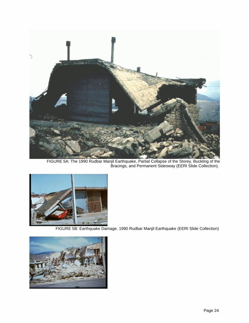
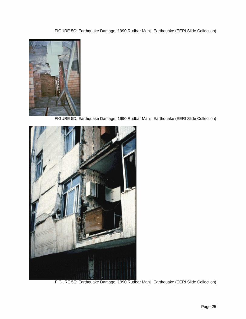
5.2 Seismic FeaturesStructural Element Seismic Deficiency Earthquake-Resilient Features Earthquake Damage PatternsWalls Cracking at the corners of un-reinforced
Relatively enough in-plane stiffness,which contributes to the lateralresistance.
Out of plane collapse, Classical X shearcracking.
Frames (columns,beams)
Buckling/collapse of the first-storeycolumns due to soft story behavior.Buckling of the braces.
Generally enough storey shearresistance. Shear failure is rare.
Buckling of the storey.
Roof and floors Insufficient roof support, vulnerabilityheight due to the weak behavior of theheavy flexible roofs.
N/A Total/partial collapse.
Connections Slippage between the girders and thecolumns. Insufficient sitting width for thegirders on the columns angelconnections.
N/A Excessive rotations, shear failure of thewelds, unsitting.
Additional Comments: Please refer to Figures
Page 9
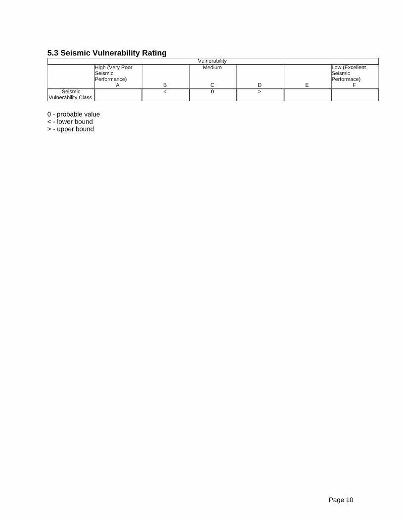
5.3 Seismic Vulnerability RatingVulnerability
High (Very PoorSeismicPerformance)
Medium Low (ExcellentSeismicPerformace)
A B C D E FSeismic
Vulnerability Class< 0 >
0 - probable value< - lower bound> - upper bound
Page 10
6 Earthquake Damage Patterns
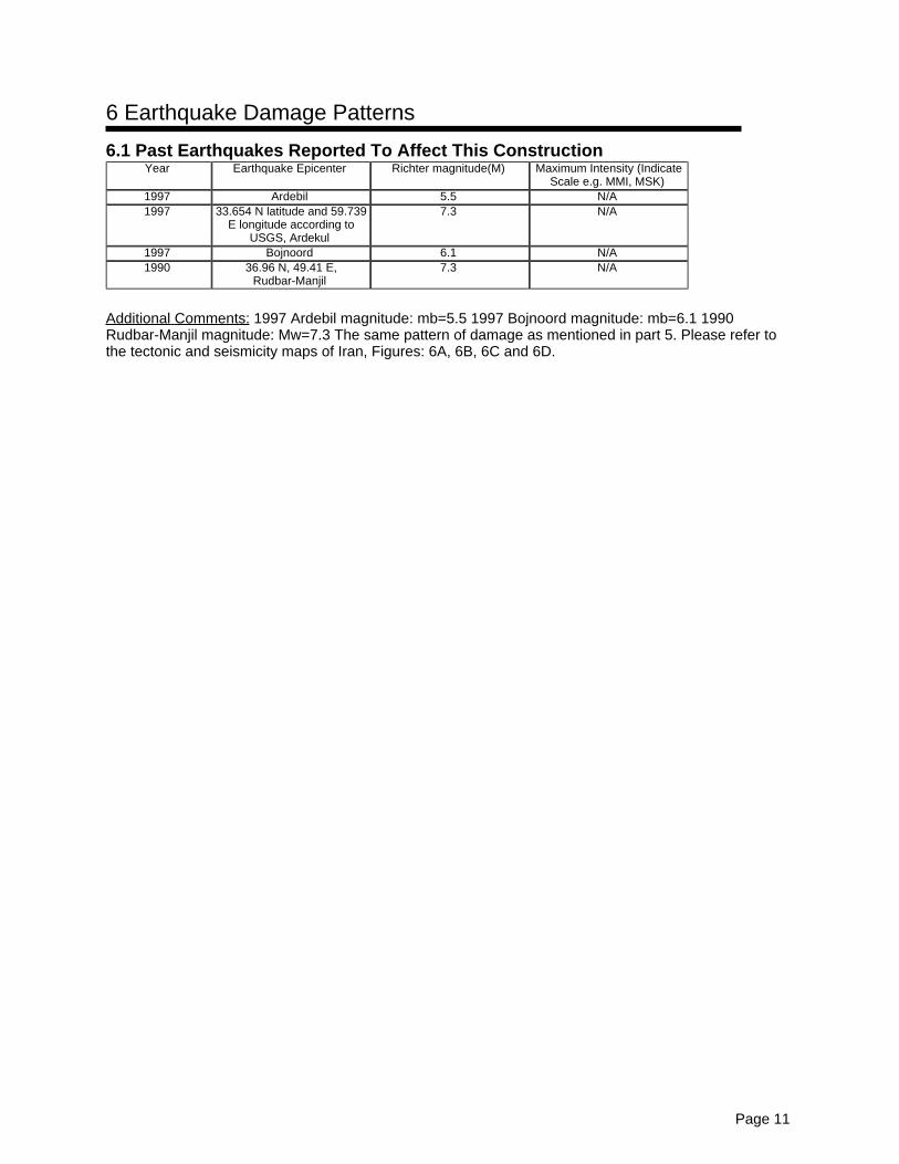
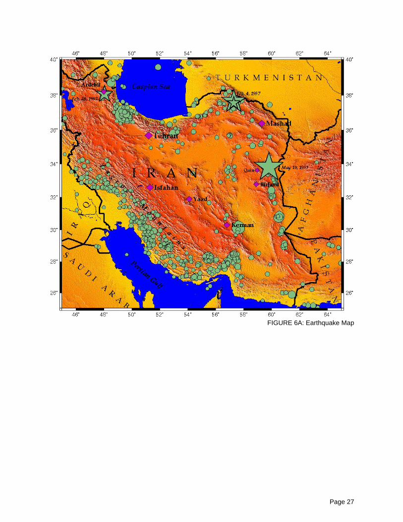
6.1 Past Earthquakes Reported To Affect This ConstructionYear Earthquake Epicenter Richter magnitude(M) Maximum Intensity (Indicate
Scale e.g. MMI, MSK)1997 Ardebil 5.5 N/A1997 33.654 N latitude and 59.739
E longitude according toUSGS, Ardekul
7.3 N/A
1997 Bojnoord 6.1 N/A1990 36.96 N, 49.41 E,
Rudbar-Manjil7.3 N/A
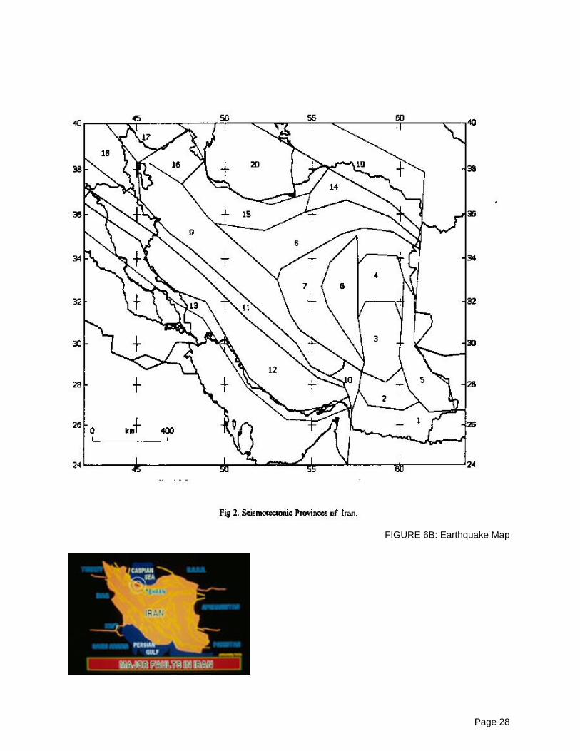
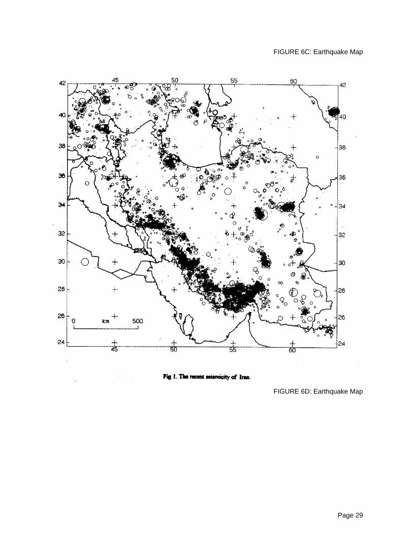
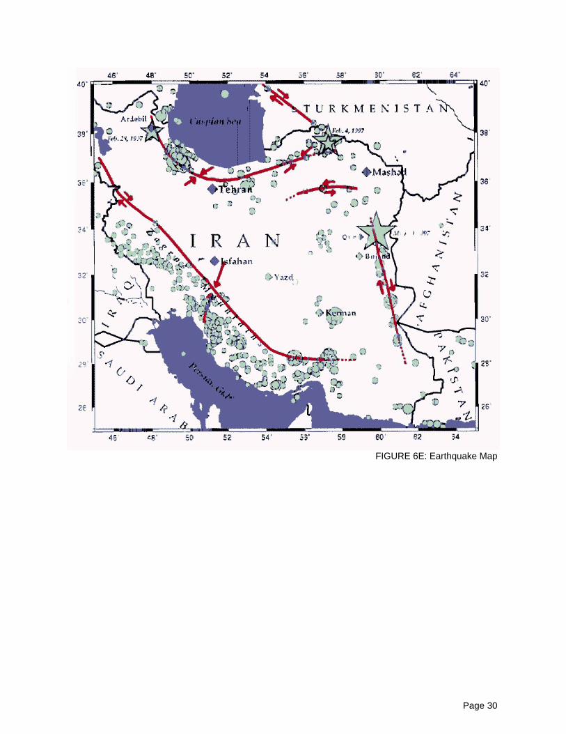
Additional Comments: 1997 Ardebil magnitude: mb=5.5 1997 Bojnoord magnitude: mb=6.1 1990Rudbar-Manjil magnitude: Mw=7.3 The same pattern of damage as mentioned in part 5. Please refer tothe tectonic and seismicity maps of Iran, Figures: 6A, 6B, 6C and 6D.
Page 11
7 Building Materials and Construction Process
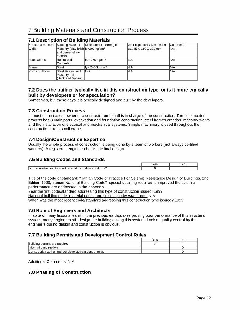
7.1 Description of Building MaterialsStructural Element Building Material Characteristic Strength Mix Proportions/ Dimensions CommentsWalls Masonry (clay brick
and cement/limemortar)
fc=200 kg/cm² 1:6, 55 X 110 X 220 mm N/A
Foundations ReinforcedConcrete
f'c= 250 kg/cm² 1:2:4 N/A
Frame Steel fy= 2400kg/cm² N/A N/ARoof and floors Steel Beams and
Masonry Infill,(Brick and Gypsum)
N/A N/A N/A
7.2 Does the builder typically live in this construction type, or is it more typicallybuilt by developers or for speculation?Sometimes, but these days it is typically designed and built by the developers.
7.3 Construction ProcessIn most of the cases, owner or a contractor on behalf is in charge of the construction. The constructionprocess has 3 main parts, excavation and foundation construction, steel frames erection, masonry worksand the installation of electrical and mechanical systems. Simple machinery is used throughout theconstruction like a small crane.
7.4 Design/Construction ExpertiseUsually the whole process of construction is being done by a team of workers (not always certifiedworkers). A registered engineer checks the final design.
7.5 Building Codes and StandardsYes No
Is this construction type addressed by codes/standards? X
Title of the code or standard: "Iranian Code of Practice For Seismic Resistance Design of Buildings, 2ndEdition 1999, Iranian National Building Code"; special detailing required to improved the seismicperformance are addressed in the appendix.Year the first code/standard addressing this type of construction issued: 1999National building code, material codes and seismic codes/standards: N.A.When was the most recent code/standard addressing this construction type issued? 1999
7.6 Role of Engineers and ArchitectsIn spite of many lessons learnt in the previous earthquakes proving poor performance of this structuralsystem, many engineers still design the buildings using this system. Lack of quality control by theengineers during design and construction is obvious.
7.7 Building Permits and Development Control RulesYes No
Building permits are required XInformal construction XConstruction authorized per development control rules X
Additional Comments: N.A.
7.8 Phasing of Construction
Page 12
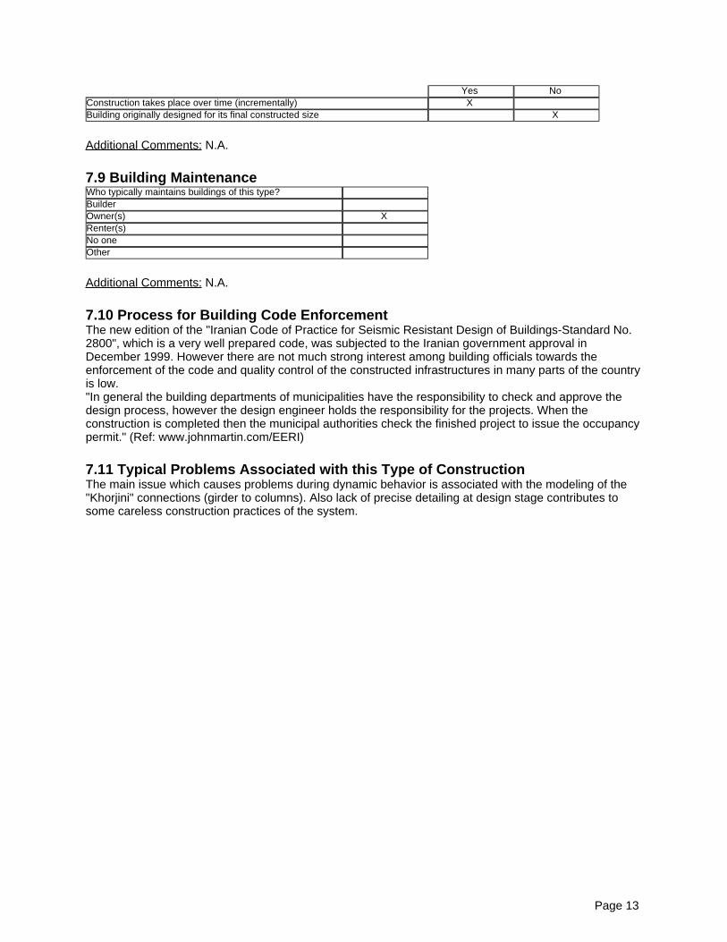
Yes NoConstruction takes place over time (incrementally) XBuilding originally designed for its final constructed size X
Additional Comments: N.A.
7.9 Building MaintenanceWho typically maintains buildings of this type?BuilderOwner(s) XRenter(s)No oneOther
Additional Comments: N.A.
7.10 Process for Building Code EnforcementThe new edition of the "Iranian Code of Practice for Seismic Resistant Design of Buildings-Standard No.2800", which is a very well prepared code, was subjected to the Iranian government approval inDecember 1999. However there are not much strong interest among building officials towards theenforcement of the code and quality control of the constructed infrastructures in many parts of the countryis low."In general the building departments of municipalities have the responsibility to check and approve thedesign process, however the design engineer holds the responsibility for the projects. When theconstruction is completed then the municipal authorities check the finished project to issue the occupancypermit." (Ref: www.johnmartin.com/EERI)
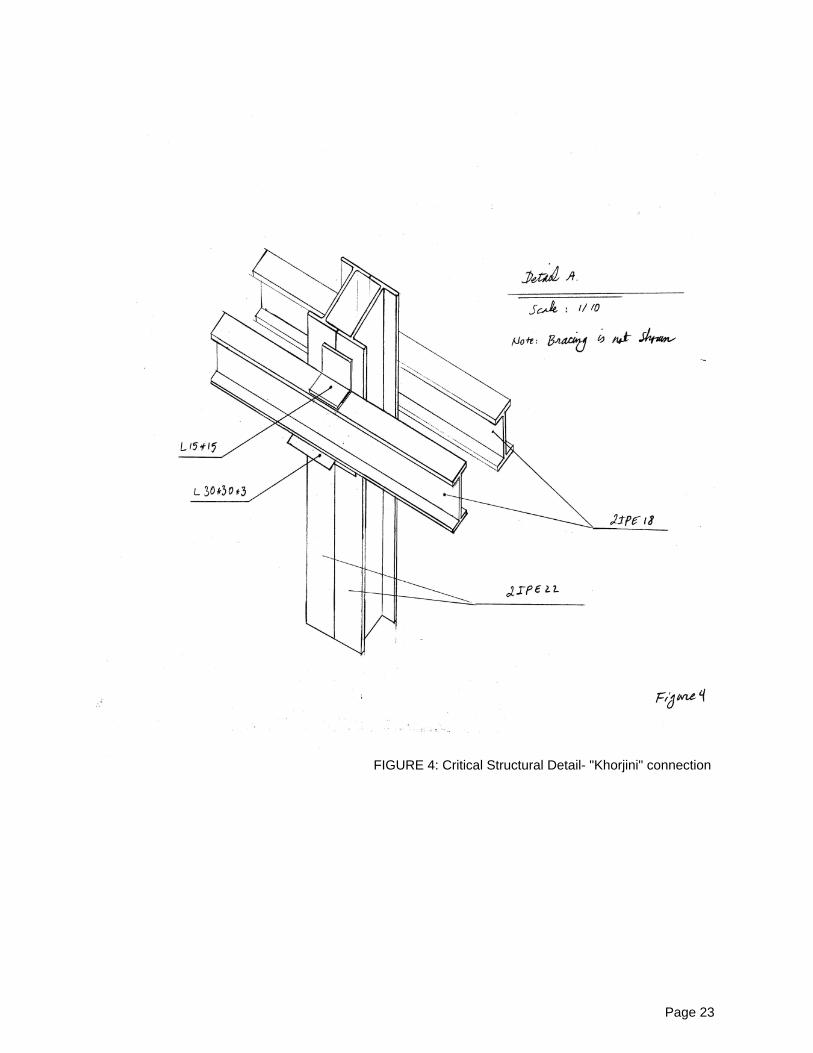
7.11 Typical Problems Associated with this Type of ConstructionThe main issue which causes problems during dynamic behavior is associated with the modeling of the"Khorjini" connections (girder to columns). Also lack of precise detailing at design stage contributes tosome careless construction practices of the system.
Page 13
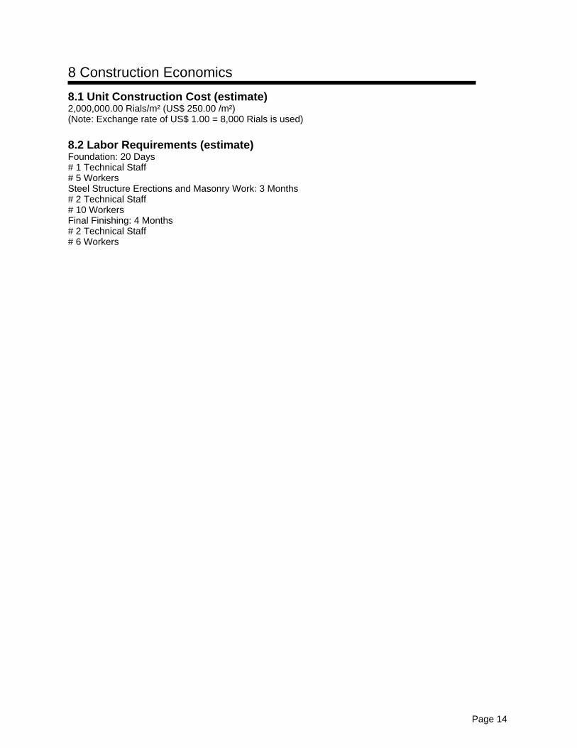
8 Construction Economics
8.1 Unit Construction Cost (estimate)2,000,000.00 Rials/m² (US$ 250.00 /m²)(Note: Exchange rate of US$ 1.00 = 8,000 Rials is used)
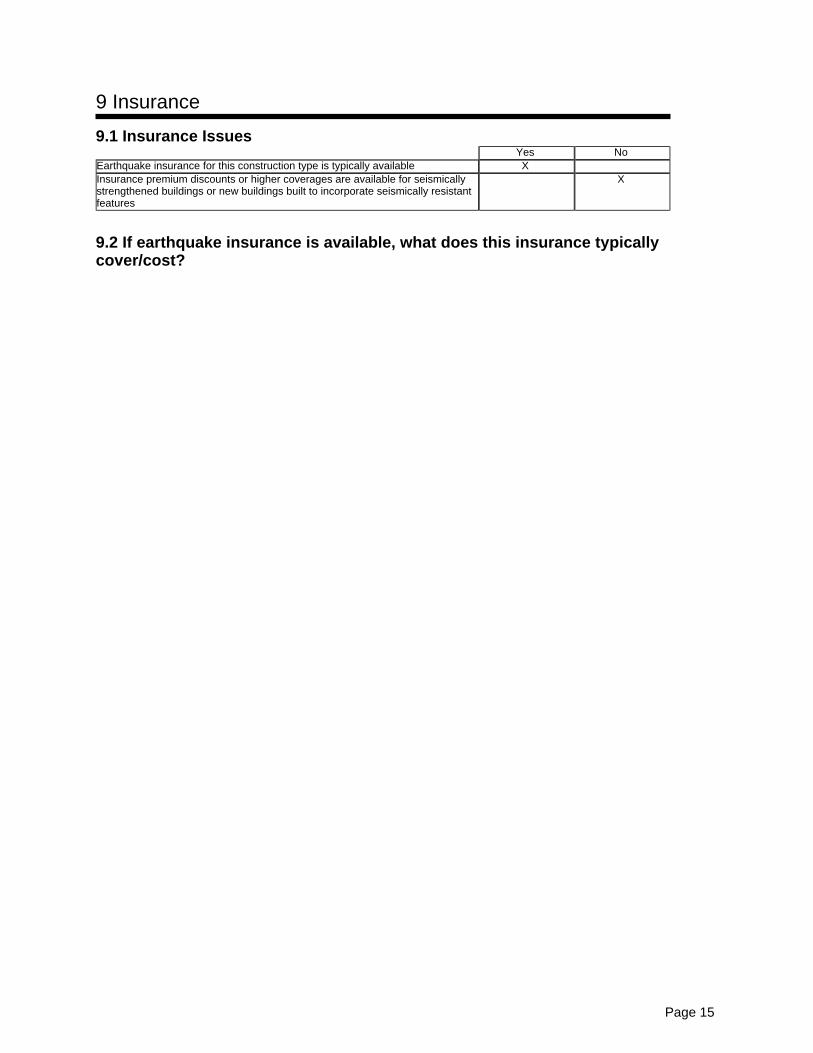
Earthquake insurance for this construction type is typically available XInsurance premium discounts or higher coverages are available for seismicallystrengthened buildings or new buildings built to incorporate seismically resistantfeatures
X
9.2 If earthquake insurance is available, what does this insurance typicallycover/cost?
Page 15
10 Seismic Strengthening Technologies
10.1 Description of Seismic Strengthening ProvisionsType of intervention Structural Deficiency Description of seismic strengthening provision usedRetrofit(Strengthening)
Out of plane wall collapse/ creaking Addition of concentric bracing to the spansPartial/ total collapse of the stories, softstorey
Adding concentric bracings
Roof collapse Horizontal bracings welded on the roof/floor beamsConnection unsitting/slippage Strengthening the connection, connection confinement using steel
plates
Additional Comments: No practical example is unfortunately available to the author at this time howeverthere are plenty research projects going on or already completed on this issues. Please refer to referenceno. 5: http://www.dena.iiees.ac.ir.
10.2 Has seismic strengthening described in the above table been performed indesign practice, and if so, to what extent?Yes, depending on the importance of the project different retrofitting strategies could be implemented.
10.3 Was the work done as a mitigation effort on an undamaged building, or asrepair following earthquake damage?Mitigation on an existing undamaged building.
10.4 Was the construction inspected in the same manner as new construction?
10.5 Who performed the construction: a contractor, or owner/user? Was anarchitect or engineer involved?Retrofit designed by an engineer, constructed by a contractor under supervision of the engineer.
10.6 What has been the performance of retrofitted buildings of this type insubsequent earthquakes?Relatively good when the code considerations are taken into account.
12 ContributorsName Arzhang AlimoradiTitle Ph.D. Candidate of Earthquake EngineeringAffiliation The University of MemphisAddress Department of Civil EngineeringCity Memphis, TNZipcode 38152Country United States of AmericaPhone (901) 678 3288 (901) 678 7920Fax (901) 678 3026Email [email protected]
Page 18
13 Figures
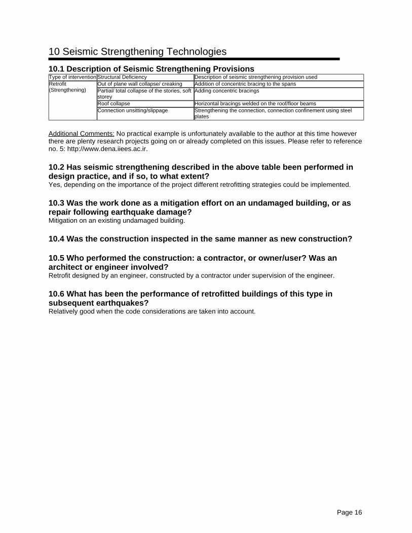
FIGURE 1A: Typical Building
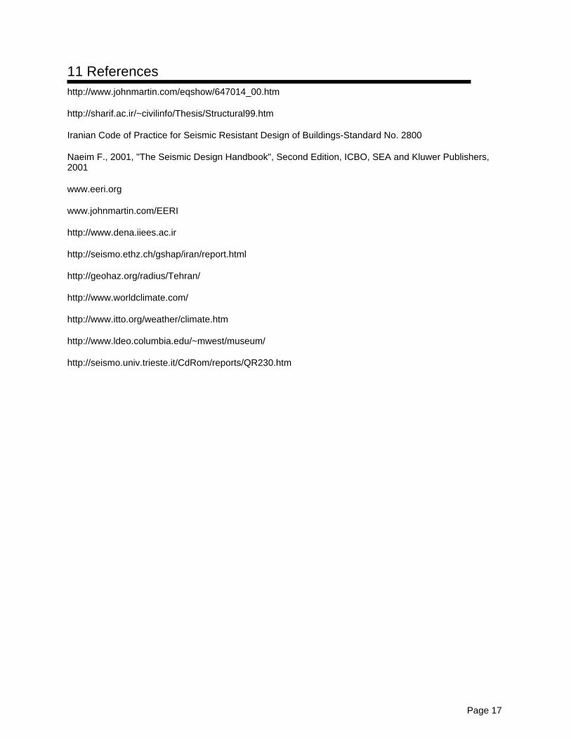
FIGURE 1B: Typical Building
Page 19
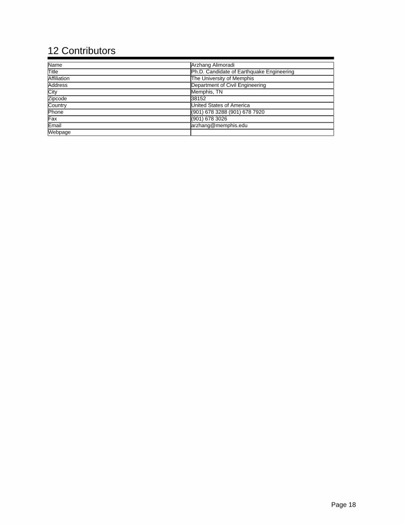
FIGURE 2A: Key Load-Bearing Elements
FIGURE 2B: Vertical elevation of a typical building showing lateral bracing