Series World Super Mitsubishi Electric Corporation's Fukuyama Works, which produces these products, is certified as meeting the ISO 14001:2004 environmental management system standard. EC97J1128 MOLDED-CASE CIRCUIT BREAKERS & EARTH-LEAKAGE CIRCUIT BREAKERS 07 A
Transcript
S e r i e s
W o r l d S u p e r
Mitsubishi Electric Corporation's Fukuyama Works, which produces these products, is certified as meeting the ISO 14001:2004 environmental management system standard.
Features 3..............................................................................................................................................
The Great Variable Accessories for Perfect Solution 9......................................................................
1. Series Configuration and List of Product Models 11......................................................................
CautionThe manual covers the product specifications for selecting an appropriate low-voltage breaker. There is the “HANDLING AND MAINTENANCE” describing how to handle the products. To use the products, separately request the “HANDLING AND MAINTENANCE”, for correct operation.
Best SolutionBest SolutionPlenty of accessories, Easy installation
24
23
2216
17
18
19
20
21
7
745
11 12 13
8
6
9
15
398
1312
2
10
1110
1
14
2
UBISHI WS Series 00A frame)
obalbalorldwide standards
CSA
UL
Mechanism
Terminal
Internal Accessories External Accessories
Breaking PerformanceRelay
Shunt-less Advanced ISTAC PA Auto-Puffer
JPT
ReliableReliableHigh reliability, Best performance
IntelligentIntelligentMeasuring and communicating
PersonalComputer
MELSECNET/10Interface card MELSECNET/10
InterfaceUnit
MDU
Eco Monitor Pro ME110S
AE-SW
PLC
I/O Unit
CC-Link®
By using various application software for PLC, users can also connect to the network SCADA system.
Global Compliance with worldwide standards
3
ASTA
TPC
TUV
CCC
LR GL BV NKDNV ABS
SABS
CSA
ULJIS
GB
EN
IEC
WS Series International Standard Conformance List
Standards
IEC JIS EN
International Japan Europe
GB
China
UL CSA LR GL DNV ABS BV NK
USA Canada
Safety Certification Marine Approvals
UK Germany Norway USA France Japan
• Compliance with worldwide standards (IEC/JIS/EN/GB/UL/CSA)• Applicable to marine approvals• New design with Laser Marking• All products with lsolation function• RoHS compliance
S e r i e s
W o r l d S u p e r
■ Full range of WS Series (up to 1600AF)
NF-CNF-S
NF-H
NF-U
NV-CNV-S
NV-H
NV-U
MCCB
ELCB
AF 125 250 400 630 800 1250 160010001606332(30)NF30-CSNF32-SW
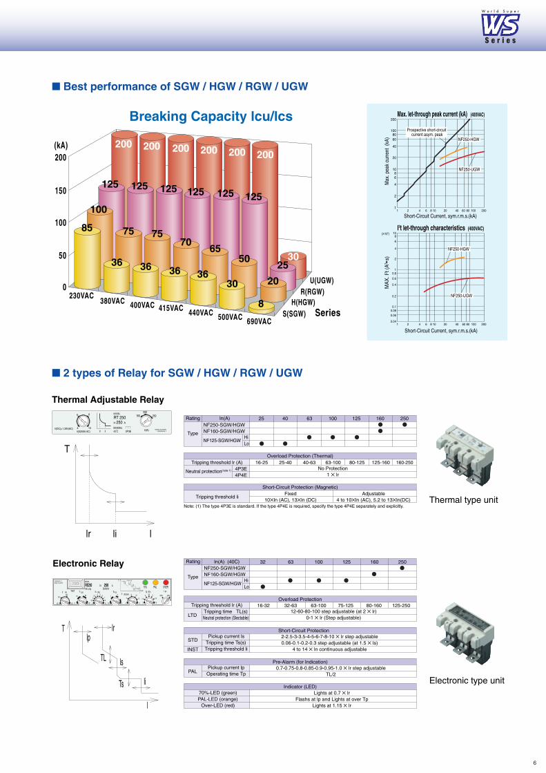
0.7-0.75-0.8-0.85-0.9-0.95-1.0 � lr step adjustableTL/2
70%-LED (green)PAL-LED (orange)
Over-LED (red)
Lights at 0.7 � lrFlashs at lp and Lights at over Tp
Lights at 1.15 � lr
Thermal type unit
Electronic type unit
S e r i e s
W o r l d S u p e r
6
7
Best Solution Plenty of Accessories, Easy installation
Hight-speed Motor DeviceMotor devices for 125-250AF become easier to use:contributing to the simple installation. � Adoption of a spring charge mechanism for high-speed operation
(0.05~0.1seconds) � Swift and simple installation by tightening only two screws.
External HandleAdoption of a safer and easy to operate handle. � Complying with protection degree IP65. � Isolation function achieved through combination with the breaker unit. � Structured to allow relay adjustments after installation as well. � Equipped with cylinder key (option) to prevent false operation.
IP-20PM with Safety Device[Adopted on SGW, HGW]Specialized for 3-and4-pole use (2 pole incompatible). � Complies with the protection degree IP20. � Safety device supplied as an option. � May be connected with up to nine leads (for PLT). � May be modified from front connection to rear connection.(Note: Modification by end users not authorized) IP20: Finger protection.
Internal accessories become easier to use by adopting a cassette type. Common use of different voltages realizes the major reduction in types. The UVT for ELCB is also available. Time delay type variations have also been expanded, offering a wide range of applications.
� Cassette-type AccessoriesCassette-type accessories give greater flexbility when upgrading circuits.Easier ordering and one-touch simple installation become possible. The insulation function increases its safety.
Fits all breaker seriesThe alarm switch (AL), auxiliary switch (AX), shunt trip (SHT), and undervoltage trip (UVT) all come as cassette-type accessories to suit all breaker series.
Product design which pursues greater ease of use by wide variationsIP-20 Terminal Connection With the SGW, HGW, connection safety has been increased. � Standard IP-20 protection
degree ensured.
Variable ConnectionsCompatible with various connection methods. Solderless terminals are now built inside the breaker contrary to the conventional style where terminals were built outside.Maximum connecting Cable of 185mm2 (SGW/HGW).(Note: Certain models have externally attached terminals)
Handle LocksWith the WS Series, ON/OFF locking is possible with the padlock.Up to three padlocks may be attached. � Customers are requested their own
padlocks.
Terminal CoverMajor improvements have been achieved in front connection terminal safety. � With terminal covers, IP40 protection
degree is ensured.(Type “SGW, HGW, RGW, UGW”)
IEC Rail Mounting for 32, 63AFThe 32,63AF includesinstallation hooks to IEC rails, greatly simplifying installation works.
OFF Lock with 3 Padlock(Type “SGW, HGW, RGW, UGW”)
ON Lock OFF Lock
PersonalComputer
MELSECNET/10Interface card MELSECNET/10
InterfaceUnit
MDU
Eco Monitor Pro ME110S
AE-SW
PLC
I/O Unit
CC-Link®
By using various application software for PLC, users can also connect to the network SCADA system.
• MDU (Measuring Display Unit) with NF 250-800AF• Small and white measuring unit• Measuring data can be transmitted to PC or PLC through CC-Link• AL / AX with CC-Link transmission• Improved accuracy(Electric energy): ±2.5% of rated value → ±2.5% of true value
Product Skelton
9
24
23
22
16
17
18
19
20
21
45
10
10
S e r i e s
W o r l d S u p e r
10
7
7
11 12 13
8
6
9
15
398
1312
2
11
1
14
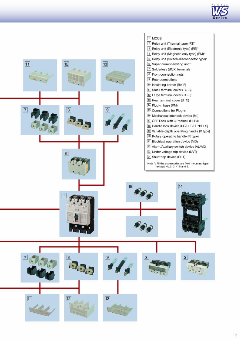
MCCB
Relay unit (Thermal type) (RT)*
Relay unit (Electronic type) (RE)*
Relay unit (Magnetic only type) (RM)*
Relay unit (Switch-disconnector type)*
Super current-limiting unit*
Solderless (BOX) terminals
Front connection nuts
Rear connections
Insulating barrier (BA-F)
Small terminal cover (TC-S)
Large terminal cover (TC-L)
Rear terminal cover (BTC)
Plug-in base (PM)
Connections for Plug-in
Mechanical interlock device (MI)
OFF Lock with 3 Padlock (HLF3)
Handle lock device (LC/HLF/HLN/HLS)
Variable-depth operating handle (V type)
Rotary operating handle (R type)
Electrical operation device (MD)
Alarm/Auxiliary switch device (AL/AX)
Under voltage trip device (UVT)
Shunt trip device (SHT)
Note *: All the accessories are field mounting typeexcept No.2, 3, 4, 5 and 6.
1
2
3
4
5
6
7
8
9
10
11
12
13
14
15
16
17
18
19
20
21
22
23
24
Series ConfigurationMolded-case circuit breakers
Earth-leakage circuit breakers
NF-CEconomy type
NF-SStandard type
NF-HHigh-performance
type
NF-UCurrent limiting-type
ultra breaker
NV-CEconomy type
NV-SStandard type
NV-HHigh-performance
type
NV-UUltra current-limiting
type
MBMotor breaker
Motor-protection breakers
NEMA-type for consumer unit DIN-series for general consumer unit
Miniature circuit breakers
BH BH-P BH-S BH-PS BH-D6 BH-DN BV-D BV-DN KB-D
For equipment
Circuit protectors
CP30-BA CP-B CP-S
11
1. Series Configuration and List of Product Models
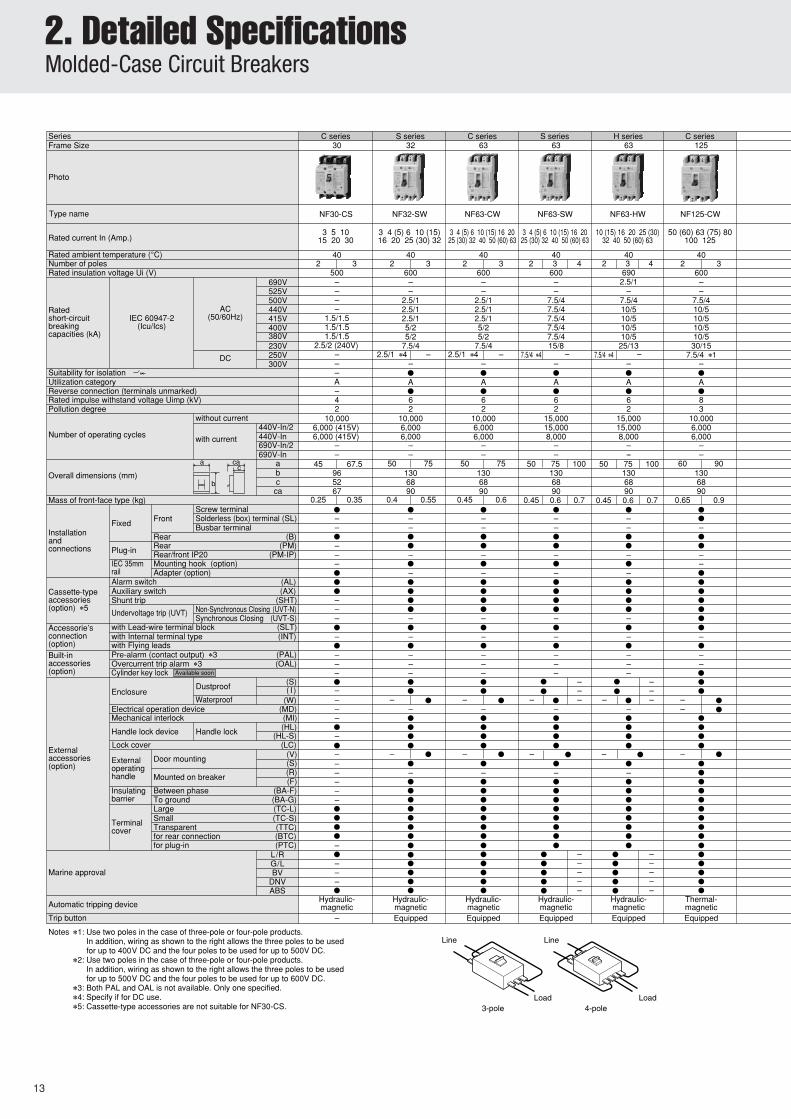
Notes ✽1: Use two poles in the case of three-pole or four-pole products.In addition, wiring as shown to the right allows the three poles to be used for up to 400V DC and the four poles to be used for up to 500V DC.
✽2: Use two poles in the case of three-pole or four-pole products.In addition, wiring as shown to the right allows the three poles to be used for up to 500V DC and the four poles to be used for up to 600V DC.
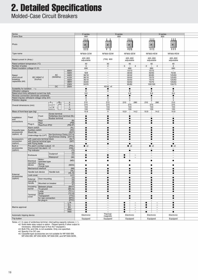
✽3: Both PAL and OAL is not available. Only one specified.✽4: Specify if for DC use.✽5: Cassette-type accessories are not suitable for NF30-CS.
Notes ✽1: Use two poles in the case of three-pole or four-pole products.In addition, wiring as shown to the right allows the three poles to be used for up to 400V DC and the four poles to be used for up to 500V DC.
✽2: Use two poles in the case of three-pole or four-pole products.In addition, wiring as shown to the right allows the three poles to be used for up to 500V DC and the four poles to be used for up to 600V DC.
✽3: Both PAL and OAL is not available. Only one specified.
Notes ✽1: In case of solderless terminal, interrupting capacity reduces: ( / ).✽2: Solid state relay output is option . Please specify if other output is
necessary. (Standard type is thus SLT equipped.)✽3: Both PAL and OAL is not available. Only one specified.✽4: Use two poles in the case of three-pole or four-pole products.
In addition, wiring as shown to the right allows the three poles to be used for up to 400V DC and the four poles to be used for up to 500V DC.
Notes ✽1: In case of solderless terminal, interrupting capacity reduces: ( / ).✽2: Solid state relay output is option . Please specify if other output is
necessary. (Standard type is thus SLT equipped.)✽3: Both PAL and OAL is not available. Only one specified.✽4: Specify if for DC use.✽5: Cassette-type accessories are not suitable for NF1000-SW, NF1250-SW, NF1250-SDW, NF1600-SW, and NF1600-SDW.
Note ✽1: 125A rated current is 3p only.✽2: Cassette-type aaccessories are not acceptable for NV30-CS.✽3: Standard type is thus SLT equipped.✽4: In case of ampere rating 15A and 16A, time-delay type is not available.✽5: Included in AL (type) only.✽6: Rated operational voltage of time-delay type is for 200-440V.✽7: Specify if for CE marking. In case of the CE marking article of 250A Frame or less, outside sizes differ.
Available soon
– � � ��
●
●
–
●●
●
●●●
●
●
●
●
●●●
●
●●
●
●●●
●●●●●
●●●●●●
●●●●●●●●
●
●●●
●
●●
●
●●●
●●●●●
●●●●●●
●●●●●●●●
●●●●●–
●●●
●●●●●
●●●●●●●●●●●●●●●●●●●●●
●
●●●
●
●●
●
●●●
●●●●●
●●●●●●
●●●●●●●●
●
Rated operational voltage
100 - 230V
100 - 440V
Available voltage range
80~253V
80~484V
200 - 440V 160~484V
32
NV32-SW
(5) 6 10 (15) 16 20 25 (30) 32
403
0.04
–
5/25/2
10/510,0006,0006,000
7513068900.6
–
–
–
–
–
–
–
Hydraulic-magneticEquipped
Button
100–440Multi-voltage type30,100•200•500
Selectable
–
–
––
�
●
●●●
●
●●
●
●●●
●●●●●
●●●●●●
●●●●●●●●
C series C series S seriesS series H series C series
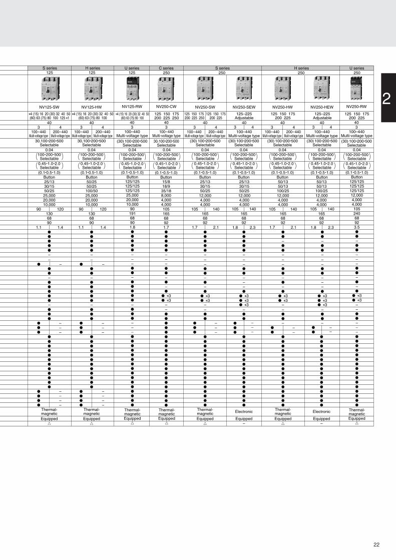
Note ✽1: In case of solderless terminal, interrupting capacity reduces: ( / )✽2: Solid state relay output is option. Please specify if order output is necessary. (Standard type is thus SLT equipped.)✽3: Rated operational voltage of time-delay type is for 200-440V.✽4: Specify if for CE marking.
Rated current In (Amp.)at ambient temperature 40°C (IEC30°C)
2 3 2 3
3-pole
Line
Load
Number of poles
Rat
ed s
hort
-circ
uit b
reak
ing
capa
citie
s (k
A)
Suitability for isolation
Reverse connection
Mass of front-connection type (kg)
Con
nect
ion
met
hod
Acc
esso
ries
✽2
(opt
ion)
Ext
erna
l acc
esso
ries
✽2
(opt
ion)
Frontconnection
Insulating barrier
Mechanical interlock
Alarm switch
Auxiliary switch
Shunt trip
Under-voltage trip
Vertical lead-wire terminal unit
Handle lock device
Operating handle
Large
Small
IEC 35mm rail fixture
TÜV type approval
Automatic tripping device
Trip button
Terminalcover
Remark: The products of which rated current is parenthesized will be produced when an order is placed.The operating characteristics of breakers are different between AC and DC (JIS and IEC only).
a cac
b
Screw terminal
Busbar terminal
Solderlessterminal (box)
Notes: ✽1 The trip action characteristics differ between AC and DC for products that are compatible to both AC and DC.✽2 Specifications for products with a CE mark differ from those for general-purpose products. Details will
be available upon request.✽3 Use two poles among the three poles in the case of three-pole products. In addition, wiring as shown to the
right allows the models of NF100-CWU, NF100-SWU and NF225-CWU to be used for up to 400 V DC and the models of NF-SFW, NF-SJW, and NF-HJW to be used for up to 500 V DC.
✽4 The standard configuration contains a protection cover and adopts the IP20 (finger protection) structure. ✽5 In case of solderless terminal, interrupting capacity reduces: (/).
26
2. Detailed SpecificationsUL Listed Products
27
epyT HB P-HB
)A(emarF 07 001 001 07 001 001
otohP
selopforebmuN 1 2 3 1 2 3
)A(Rated current04erutarepmettneibmata ° C
Rated voltage (V)CA 230/400
CD 125
IEC 608983
3
— 1
230/400
125
1
snoisnemiD)mm(
a 52 05 57 52 05 57
b 59 47
c 5.75 5.06
ac 5.77 97
Mass (kg) 0.16 0.32 0.48 0.13 0.26 0.38
n ✳1oitcennoC
lanimretpmalC )daol(pmalC)enil(ni-gulP
ecivedgnippirtcitamotuA citengam,lamrehT
Optionalaccessories
revoclanimreT —
etalpgnitnuoM —
esablanimreT —
revockcoL
ybdevorppA —
—
—
3
3
—
—
KN,LG,RL — — KN,LG,BA,VB,RL —
✳1. If reguired Solderless terminal can be supplied. (BH : Line and Load side, BH-P : Load side only)
DC125V
AC230/400V
AC400VBreaking capacity(kA) sym.
Type of instantaneous operation Type C (5 In <, <10 In)
✳ 1. The 3P products are use for AC only.✳ 2. Contact us for operating characteristics other than those mentioned above.✳ 3. In the pole with a shunt tripping apparatus, an over-current tripping element becomes nothing. (Switched type shunt tripping type)✳ 4. In the case of back wiring terminals, specify if it will be used with ratings 20A or less, or 30A.✳ 5. UL(cURus), CCC, and CE Marking are displayed on standard products.✳ 6. It is recognition of UL(cURus), CCC, and TUV.✳ 7. In case of DC use, only DC65V is available.✳ 8. Specify if for DC use when ordering.✳ 9. Specify when ordering. (In case of CP-S UL, type name is CP-SU.)✳ 10. Connection is male tub terminal only.✳ 11. CP30-BA only.Remark (1) The non-standard conditions products are also made by your order.
(Low temperature, Moisture-fungus treatment of the 1st kind, Moisture-fungus treatment of the 2nd kind, Corrosion resistive.)(2) Although buzzing sound may be made if an instantaneous type becomes 80% or more of rated current when it is used by AC, there is no problem on a performance.
Therefore, when used in a quiet environment, please select after taking this point into consideration.(3) Please use it in a circumference environment without temperature, humidity, dust, corrosive gas, vibration, and impact.
And please do not use it in a circuit with inrush current, and a circuit with harmonics. It may become unnecessary action or trouble.
3. Special Purpose BreakersMag Only, DC-Use And DSN-Type
Mag Only (Instantaneous tripping circuit breakers)
Remarks: 1. The size, weight, accessories, etc., are all identical to the same-designation C, S
and H series breakers.
2. For more detail, contact your dealer.
DC-Use MCCBs and DSN-type Switches
•DSN-type switchesThese are standard MCCBs without the automatictripping element. The tripping capacity is about sixtimes the rated current.
The appearance, size, drilling plan and availableaccessories are all identical to similar type standard Sand C series MCCBs.
Breaking is more difficult with direct currents becausethe current value never reaches zero. While ordinaryDC breakers are suitable for low voltages, specialvoltage DC breakers are recommended for voltages inexcess of 250VDC. Breakers for 550V are all 4-polemodels.The size, shape, drilling plan, accessories, etc., are allidentical to the S series of same-designation breakers.
Notes: 1: Time constant: 10ms or below.
•DC sideThese breakers are designed as thyristor-Leonardsystem DC-side breakers. They protect the thyristorfrom short circuiting when there is a power or
communication failure. (Mag-Only breakers can alsobe used for this role.) Use these breakers incombination with fast fuses for even greater protection.
Note: The tripping characteristics will change if the wiring differs from the oneshown here.
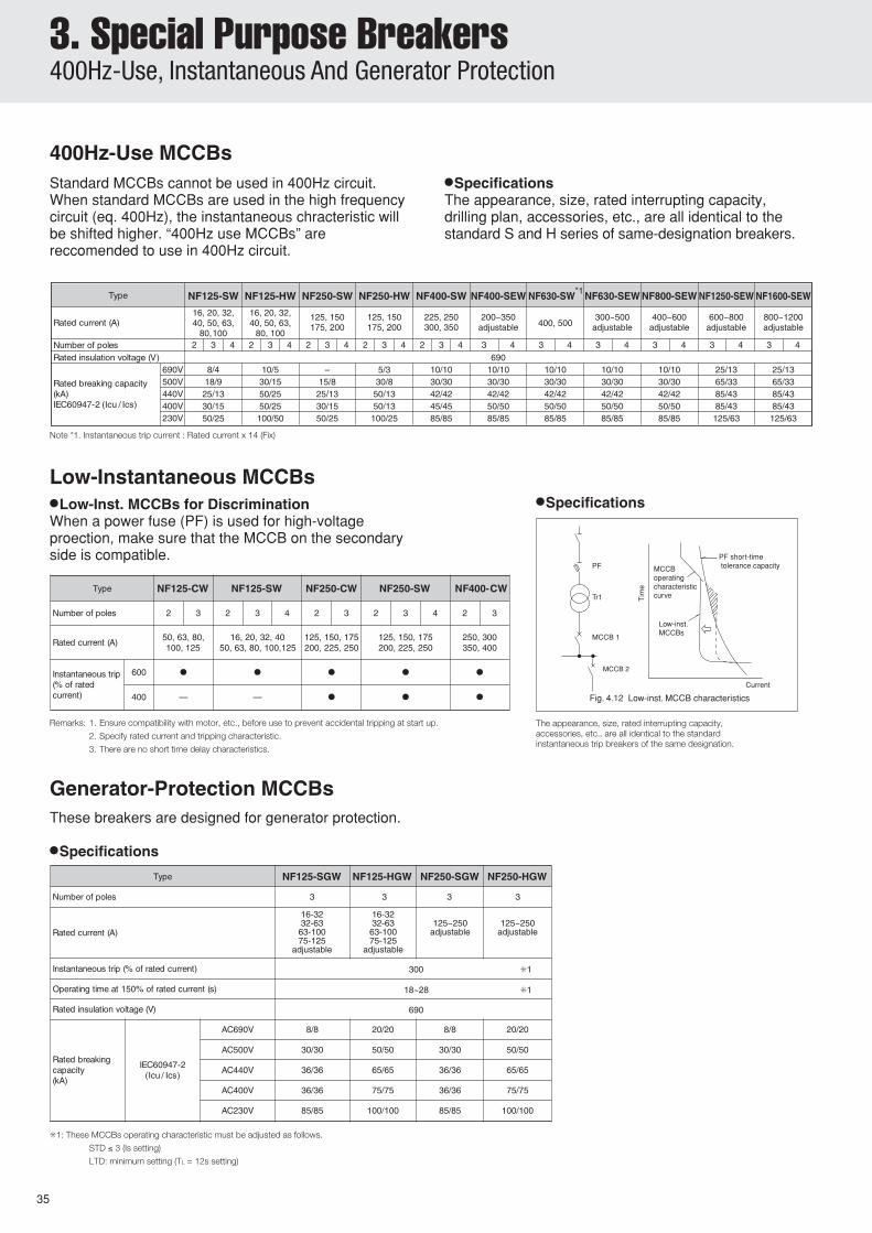
3. Special Purpose Breakers400Hz-Use, Instantaneous And Generator Protection
PF
Tr1
MCCB 1
MCCB 2
Tim
e
Current
Low-inst. MCCBs
MCCBoperatingcharacteristiccurve
PF short-time tolerance capacity
Fig. 4.12 Low-inst. MCCB characteristics
✳1: These MCCBs operating characteristic must be adjusted as follows.
STD ≤ 3 (Is setting)
LTD: minimum setting (TL = 12s setting)
These breakers are designed for generator protection.
•Specifications
Standard MCCBs cannot be used in 400Hz circuit.When standard MCCBs are used in the high frequencycircuit (eq. 400Hz), the instantaneous chracteristic willbe shifted higher. “400Hz use MCCBs” arereccomended to use in 400Hz circuit.
•SpecificationsThe appearance, size, rated interrupting capacity,drilling plan, accessories, etc., are all identical to thestandard S and H series of same-designation breakers.
•Low-Inst. MCCBs for DiscriminationWhen a power fuse (PF) is used for high-voltageproection, make sure that the MCCB on the secondaryside is compatible.
Remarks: 1. Ensure compatibility with motor, etc., before use to prevent accidental tripping at start up.
2. Specify rated current and tripping characteristic.
3. There are no short time delay characteristics.
The appearance, size, rated interrupting capacity,accessories, etc., are all identical to the standardinstantaneous trip breakers of the same designation.
•Specifications
Note *1. Instantaneous trip current : Rated current x 14 (Fix)
• Energy management becomes possible by measurement and display of loadcurrent, line voltage, electric power, electric energy, harmonic current (3rd, 5th,7th, 9th, 11th, 13th, 15th, 17th, 19th, and total) and power factor.
• MDU with pulse output option can output pulse of electric energy. MDU with CC-Link option can transfer measured data to open network CC-Link.• When a circuit breaker outputs an alarm, LED on MDU turns on.
PAL : pre-alarmOVER : over current
• When the circuit breaker has tripped, fault cause and fault current stored inEEPROM. It makes investigation of cause and restoration of power line possible.
• The max. demand value of load current, line voltage, total harmonic current,electric power and electric energy (hourly value), are stored in EEPROM.
And MDU with CC-Link option can store the outbreak time of these. It makes easyfinding of peak time of power consumption possible.
NF400-SEP with MDU
Load current (Present value, demand value, maximum demand value)
Line voltage (Present value, maximum value)
Harmonic current (Present value, demand value, maximum demand value)
Electric power (Present value, demand value, maximum demand value)
Electric energy, electric energy (hourly value),
maximum electric energy (hourly value)
Power factor (Present value)
Rated measuring current
Accuracy of measuring current (Limit deviation tolerance)
Rated measuring voltage
Accuracy of measuring voltage (Limit deviation tolerance)
Maximum measuring current (Note1.)
Maximum measuring harmonic current (Note1.)
Maximum measuring voltage (Note1.)
Measurement range of power factor
NF250-SW
with MDU
250
125, 150, 175,
200, 225, 250
250A
±6.25A
AC440V
±11V
AC690V
Lead 0.0~100.0~0.0 Lag(%),
The value of power factor is reference value if less than 50%.
PAL, OVER
3φ3W, 1φ3W (3 poles breaker), 3φ4W (4 poles breaker)
AC/DC100-240V 12VA (Note5.)
PAL
NF400-SEPNF400-HEPwith MDU
400
200-400
adjustable
400A
±10A
NF630-SEPNF630-HEPwith MDU
630
300-630
adjustable
630A
±15.76A
NF800-SEPNF800-HEPwith MDU
800
400-800
adjustable
800A
±20A
500A
250A
800A
400A
The fault cause: “AL” isdisplayed. The fault current: Itdisplays it up to 10 times the
rated current.(“AL switch for the MDUtransmission” (option) is
necessary. )
The fault cause: Overload “L” and short-circuit “SI” aredisplayed.
The fault current: It displays it up to 16 times themaximum rated current.
1260A
630A
– PAL, OAL
1600A
800A
Note1. When the input becomes more than the measurement maximum value, the current, the voltage, the harmonic current, and the fault current display the measurement maximum value. It does the blinking display.(However, when the fault occurs, the fault cause of and the fault current measurement value do the blinking display though it is less than measurement maximum value.)When electric power becomes more than the measurement maximum value of or either the current or the voltage becomes more than its measurement maximum value, the electric power does the blinking display.
Note2. Either of overload (L) or short-circuit (SI) is displayed. It doesn’t display it at the same time.Note3. Pulse output option and CC-Link option cannot be attached at the same time.Note4. When the breaker mounting type of MDU is installed, the version of CC-Link is “Ver.1.10”.
When the panel mounting type of MDU is installed, the version of CC-Link cable (FANC-SB) used for the terminal stand from the surface of MDU to the other side is “CC-Link Ver.1.00”.Note5. When control power supplied to MDU, then rushed current transitionally, max. 2Apeak, 1ms (at 240VAC).Note6. The module (terminal) is attached to the right side of the breaker.
Pre-alarm (PAL) output function can set “Self-holding” or “Auto reset”.For function of alarm contact output (PAL, OAL), MDU and the circuit breaker must be connected with the mutuality and the control power must be supplied to MDU and alarm contact output module.
Note7. In the case of panel mounting, the part set (the panel holder plate, the screws, the nuts and the MDU connection cable) is packed. And, the MDU connection cable is 2m (standard). (MDU connection cable can be specified by 0.5m, 3m, and as many as 5m.)
Measured
and
displayed
value
Application type
Type
Frame size
Alarm LED indication
Phasing line
Electric energy accumulated pulse output (option) (Note3.)
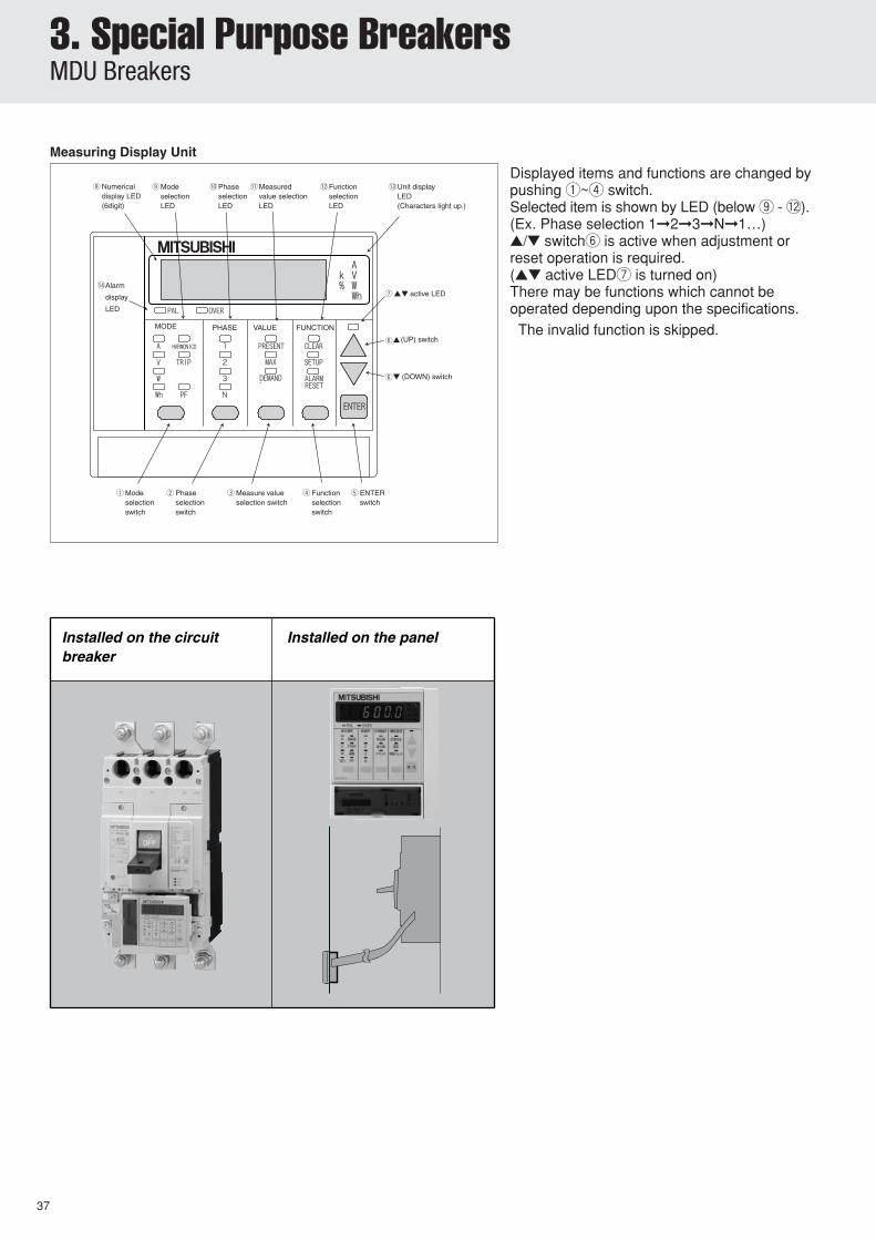
Displayed items and functions are changed bypushing q~r switch.Selected item is shown by LED (below o - !2).(Ex. Phase selection 1➞2➞3➞N➞1…)▲/▼ switchy is active when adjustment orreset operation is required.(▲▼ active LEDu is turned on)There may be functions which cannot beoperated depending upon the specifications. The invalid function is skipped.
Installed on the circuit breaker
Installed on the panel
Measuring Display Unit
3. Special Purpose BreakersMDU Breakers
3
38
1mm clearance on eachside of handle.
(Load side of breaker mounting has given the space to pass wires to the terminal.)
Panel holder plate
MDU connectorTerminal blockM3 nut
M4 screw
M3.5screw
Terminal PE screw (M4)
Panel
Terminalcover M3 nut
M4 screw
Upperside
Operation/display
side
Front panel cutout
MDU is connected with circuit breaker via MDU connection cable.
For the setinstallation
MDU displaypart
Panelthickness1~3.2mm
In case of front connection,keep space between MDU and conductor or insulation barrier too.
Space greater than the valueshown in the figure below must be secured, and must beseparate 10cm or more from thedistribution line.
Breaker
Mounting hole
Insulating barrier(removable)
Tripbutton
M8 bolt(Hex-soket)
MDU
(Bus t max.=7)
MDUterminalcover
Insulatingtube
MDU
Breaker
Drilling plan
Mounting hole
Insulating barrier(removable)
Tripbutton
Neutralpole
MDUterminalcover
Breaker
M4✕0.7 tapsor φ5
MDU
Stud can berotated 90°
Mounting platet max. 3.2
Insulating tube
φ9M8 bolt
Breaker
M4✕0.7 tapsor φ5
Drilling plan
φ24
Breaker
φ24
Bus drilling fordirect connection
Connectionallowance
90
1228
.5
75
70
40
728.
5 58.5
30
54
96 85
72
86.5
40
40
R275
90
32.5R1
3-pole
4-pole
52
100
3-pole
4-pole
32.5
2014
4
150
26
2468724
92100
90
105
102
50
3775
45
6130
φ4.5φ8
.5
23 max.
10
70
100
165
144
22
100
φ8.5
8
105
6
70
3-pole
4-pole
35
126
102
90
140
35
105
105
50
100
165
144
2210
0 35 35
126
68
72492
100
3775
45
61
30
φ4.5
φ8.5 22
71
106
15 1570
126
144
35
35
105
198
158
<Breaker mounting> <Panel mounting>
3-pole 4-pole
3-pole 4-pole
3-pole 4-pole
Front-plate cutout
Front-Connection
Rear-Connection
MDU panel mounting
NF250-SW with MDU
NF250-SW with MDU (No transmission, Pulse output)
CC-Link ; only MDU panel mounting
<Panel mounting>
<Breaker mounting>
MDU Terminal
6
L1L2
Terminal block
4
21
L2L1
3
Control power
No transmission
Pulse output 113
1 2 3 4
1 2 3 4 5
114
FG
FG 113 114
No transmission
Pulse output
1 2 3 4 5 6
Control power
100
R1
35 35M4✕0.7breakermounting screw
39
MDU is connected with circuit breaker via MDU connection cable.
Upper side
Figure of the breaker mountingis removed the terminal cover.
M3 screw
Panel
Panel holder plate
Operation/displayside
MDUconnector
Terminal block
M3 nut
M3screw
Terminal PE screw(M4)
Terminal cover
M3 nut
M3 screw
Front panel cutout
For the setinstallation
MDU displaypart
Panelthickness1~3.2mm
Space greater than the valueshown in the figure below must be secured, and must beseparate 10cm or more from thedistribution line.
In case of front connection,keep space between MDU and conductor or insulation barrier too.
769085
58.5
72
86.5
40
R275
90
104.
5
55
23
67.5
38
48
43.1
75
7012
28.5
96
218
158
MDU panel mounting
NF250-SW with MDU (CC-Link)
<Panel mounting>
MDU Terminal
<Breaker mounting>
L2L1
1234567
Control power
8
7DASLD DG DB
65 8
SLD DG DB DA
1 2 3 4
L1L2 1 2 3 4 5 6
Control power
Terminal block
SLD DG DB DAFG
654321
3. Special Purpose BreakersMDU Breakers
3
40
MDU is connected with circuit breaker via MDU connection cable.
<Panel mounting>
<Breaker mounting>
1mm clearance on each
(Load side of breaker mounting has given the space to pass wires to the terminal.)
Figure of the breaker mountingis removed the terminal cover.
Panel holder plate
MDU connectorTerminal blockM3 nut
M4 screw
M3.5screw
Terminal PE screw (M4)
Panel
Terminal cover
M3 nut
M4 screw
Operation/displayside
Front panel cutout
For the setinstallation
MDU displaypart
Panelthickness1~3.2mm
Space greater than the value
shown in the figure below
must be secured, and must be
separate 10cm or more from the
distribution line.
Upperside
1228
.5
75
70
40
728.
5
58.5
30
54
96
72
86.5
40
40
R275
90
4613
8
R6 R6
92
103
97
102
MDU
Mounting hole
39
Insulating barrier(removable)
φ14M12 bolt
4-pole3-pole
110
φ12.
5
φ7
8
44
47
39
196
18525
7
168
φ10.5
12
Breaker
Drilling plan
3-pole 4-pole
194
16
43
28
PE
4-pole
3-pole
194
225
8
25 20
20
MDUMounting plate
φ13M12 bolt
10
26
83
128
8
87
14
130.5
Breaker
φ35
3-pole
Drilling plan
4-pole
44
87
44
43.5
130.5
Note:The drilling plan is different if insulating barriers are installed. CC-Link ; only MDU panel mounting
3-pole3-pole
<Panel mounting><Breaker mounting>
Breaker
Tripbutton
Currentindication LED
OVER PAL 70%
MDUterminalcover
Neutralpole
Conductort max.=8
Conductor t max.=8Conductor drilling fordirect connection
The front connection model will be delivered unless otherwise specified. Notice, however, that you can convert the front connection model to other types (excluding the plug-in) by using an appropriate connection component, which is separately available.
✽1
3. Connection of Line and LoadThe standard wiring of line and load on the circuit breaker is (a) normal connection shown on the right. Avoid the wiring shown in (b) reverse connection, which may lead to the decrease in breaking performance. However, the reverse connection is allowed for the following models (except NF models with MDU).
Line
Line
Load
Load
Normal connection (a)
Normal and reverse connection methods
Reserve connection (b)NF-C series, NF-S series, NF-H series, NF-U series,MB series, C • S • H series of NV400~800A Frame Reverse connection is allowed for the standard models.
Notes: ✽ 1 You can use the plug-in terminal unit (PM) when the wiring of terminal units is required in advance, and the delivery of both the main body and the components at the same time, which is normal, is not allowed. Furthermore specify the nonuse of plug-in terminal (PM-N) for the connection of circuit breaker.
✽ 2 If safety device is necessary ,please require.✽ 3 Connected wire size: 2.5~25mm2
✽ 4 Connected wire size: 25~70mm2
✽ 5 Connected wire size: 14~95mm2
✽ 6 Connected wire size: 70~125mm2
Table 4-2: List of Connection AccessoriesType name
Note: *1. When DC use polarity must be considered.Please contact us for applications in the field of smaller current values.
A control power supply (compatible to 100 and 200V AC) is required; see the diagram on the right showing its wiring. (The permissible range of voltage of the control power supply is 80 to 242V AC, and the power requirement is 10VA.)
Table 5-6: AL·AX·EAL Switch Rating (In case of EAL, 400AF and more)
Table 5-3: AX Switch Operation
Table 5-4: EAL Switch Operation
Table 5-5: MG Switch Operation
Table 5-7: EAL Switch Rating (250AF and less)
Internal accessories Function Applicable models Cassette-type of accessories
AL Alarm switch A switch that electrically indicates the trip status of the circuit breaker. NF-C·S·H·U,NV-C·S·H·Uand MB seriesAX Auxiliary switch A switch that electrically indicates the ON-OFF status of the circuit breaker.
SHT Shunt tripA device that electrically trips the circuit breaker from a remote distance. Permissible working voltages are 70 to 110% of the AC rated voltage or 70 to 125% of the DC rated voltage.
A device that automatically trips the circuit breaker if the voltage is lowered. Working voltages are 70 to 35% of the UVT rated voltage. When the voltage recovers to 85% or higher, you can reset the device and put into operation.
EAL Earth-leakage alarm switchA switch that electrically indicates the trip status of the earth leakage circuit breaker caused by a ground fault. If 250AF and less, This switch is available only for models with the vertical lead-wire terminal unit (SLT).
NV-C·S·H·U –
TBM Test button moduleThis module allows you a remote testing by applying a voltage.An external sequence common to SHT can be used. (The standard configuration requires the vertical lead-wire terminal unit (SLT).)
NV-C·S·H·U –
MG Insulation switch The incorporation of this switch enables the measurement of insulation resistance between the terminals of the load with the circuit breaker being turned OFF. NV-C·S·H·U –
PAL Pre-alarm module
OAL Overcurrent trip alarm switch
Indicates that the load current exceeds the pre-alarm setting current.
Indicates that the breaker has been tripped by overcurrent or short-circuit current.
Electronic Types –
Electronic Types(SGW, HGW, RGW, UGW) –
Circuit breaker status AL switch contact
Circuit breaker status AX switch contact
Circuit breaker status
Circuit breaker status MG switch status
EAL switch contact
Switch type
AC DC
Voltage(V)
Current (A) Voltage(V)
Current (A)
Resistive load
Inductive load
Resistive load
Inductive load
Resistive load
Inductive load
S
V
X
460 – – 250 0.2 0.2
250 3 2 125 0.4 0.4
125 5 3 30 4 3
460
250
125
460
250
125
5
10
10
5
10
10
2
10
10
2.5
10
10
250
125
30
250
125
30
0.3
0.6
10
5
10
10
0.3
0.6
6
3
6
10
AC
Voltage
(V)
Current A
200 3 2
100 3 2
1. AccessoriesTable 5-1: Accessories
2. Switch Operation and RatingTable 5-2: AL Switch Operation
●
●
●
●
*1
5. AccessoriesInternal Accessories
5
44
3. Maximum Number of Internally Mounted Accessories
Table 5-8: Combinations of Accessories
Remarks: (1) Circled numbers indicate the order of installation.(2) Accessories of EAL, and TBM can be installed independent of installations of AL, AX, and MG. (Two units among EAL, and TBM cannot be installed at the same time.)
Notes: (1) Second AX can substitute the AL on the left-pole.(2) Models with UVT require a UVT voltage module to be installed on the lead-wire terminal unit. (No such voltage module is required for SHT.) Part of UVT accessories is not of
cassette type. (Details will be available upon request.)(3) UVTs for left-pole installation can be produced, if specified, for frame current values of 125A (excluding SGW/HGW/RGW/UGW).(4) SHT cannot be installed.(5) EALs are available only for models with the vertical lead-wire terminal unit (SLT). Specify a control power supply of either 100 or 200 V AC.(6) Models NV250-SEW/HEW are not allowed to install the UVT device.(7) The standard lead drawing is performed laterally. Load drawing is also available.(8) Only the models with an SLT are available. EAL and PAL require a control power supply (shared 100 - 200 VAC).
For the 24 VDC TBM only, instruct us of a control voltage. (The standard shared voltage is 100 - 240 VAC/100 - 240 VDC.)(9) Models CE marking are not allowed to install the TBM device.
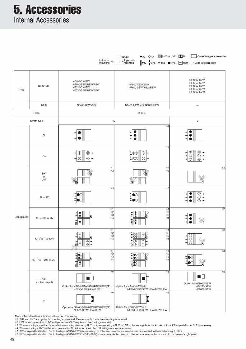
The number within the circle shows the order of mounting.).ylsuoenatlumisdetnuomebtonnacsMBTrosLBT,sLAEowt,revewoH(.seirosseccaGMdnaTVU,THS,XA,LAforebmunehtfosseldragerdetnuomebnacMBTdna,LBT,LAE.1
Option for NV400-SEW/HEW/REWNV630-SEW/HEW Option for NV800-SEW/HEW
Option for NV400-SEW/HEW/REWNV630-SEW/HEW Option for NV800-SEW/HEW
5
48
Left-sidemounting
Right-sidemounting
Handle AL AX SHT or UVT
epyT NF-C/S/H
seloP
epythctiwS S S
32 3
seirosseccA
AL
AX
SHTor
UVT
AL + AX
AL + SHT or UVT
AX + SHT or UVT
AL + AX + SHTor
UVT
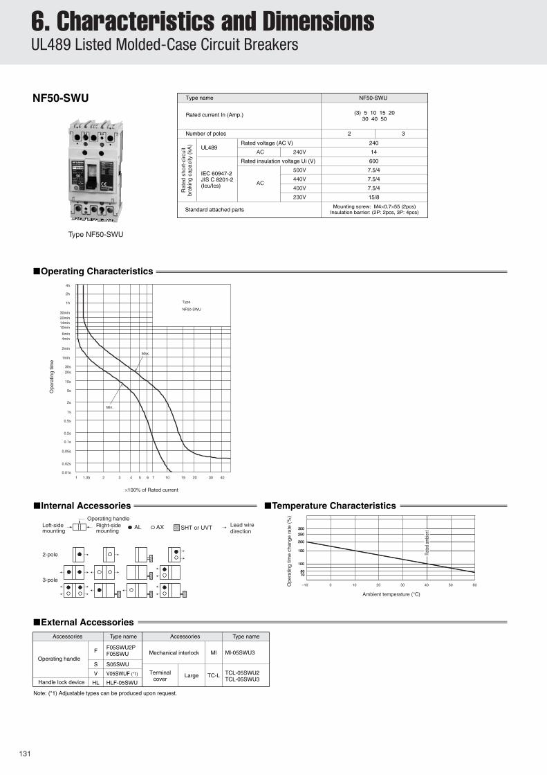
NF50-SWUNF100-CWUNF100-SWU
NF50-SWUNF100-CWUNF100-SWU
NF-SFWNF-SJWNF-HJW
NF225-CWU NF-SKW NF-SLW
Remarks: (1) Encircled numbers show the order of mounting.
Notes: (1) If a UVT is used, a UVT voltage module is installed on the lead wire terminal block. (The SHT requires no voltage module.)(2) If a UVT is used, a UVT voltage module is installed on the lead wire terminal block. (The SHT requires no voltage module.) No cassette is attached to the UVT.(3) If a UVT is used, the UVT voltage module is externally installed. (The SHT requires no voltage module).(4) The 2nd AX can be installed instead of the AL on the left pole.(5) The standard mounting of the SHT and the UVT is performed on the right pole. If mounting on the left pole is required, instruct us. (The UVTs for interlocks are mounted on the left pole.)(6) We can manufacture the SLTs used when 3 or more accessories are installed on the left pole and the SLTs used when the AL and the AX are attached on the same pole that is
attached with the SHT or the UVT at your order.(7) If a UVT is used and an AL, an AX or an AL + an AX are attached to the same pole that is attached with the UVT, the UVT voltage module is separately installed.
(Note 1) (Note 1)
(Note 4)
(Note 1)
(Note 1)
(Note 1)(Note 4)
(Note 1)
(Note 4)
(Note 1)
(Note 1)
(Note 1)(Note 4)
(Note 2)
(Note 6)
(Note 6)
(Note 2)
(Note 5)(Note 7)
(Note 1)(Note 6)
(Note 5)(Note 7)
(Note 5)(Note 7)
(Note 1)(Note 6)
(Note 1)(Note 6)
(Note 4) (Note 6)
(Note 2)
(Note 2)
(Note 2)(Note 4)
(Note 2)
(Note 5)(Note 7)
(Note 1)(Note 6)
(Note 5)(Note 7)
(Note 1)(Note 6)
(Note 5)(Note 7)
(Note 1)(Note 6)
(Note 6)
2 4
1 31 2
1 2
1 2
1 2
1 2
1 2
1 2
1 2
1 2
1 2
32
1
1 2
1 2
2 4
1
6
5 3
2
1
4
35
4
3
2
1
UVT Voltage Module Wiring Diagram(Lead-Wire Connection)
J1/UC1
J2/UC2
Circuitbreaker
UVT voltage module
D1/P1
J1/UC1
J2/UC2
D3/P3
D2/P2
4. Shunt Trip (SHT)Table 5-9: Standard Coil Rating
5. Undervoltage Trip (UVT)● UVT Voltage Module
Notes: (1) Secure a sufficient input power so that the voltage will not drop below the permissible lower working voltage (70% of the lowest rated voltage).(2) The operating time denotes the time from when the rated voltage is applied to SHT until when the main contact of the breaker starts to open.
The UVT voltage module is normally installed on the vertical lead-wire terminal unit (SLT). (A separate-mount type can be produced upon request.)
Notes: (1) A desired voltage can be selected by changing the terminal wiring.(2) The operating time denotes the time from when no voltage is applied to UVT until when the main contact of the breaker
starts to open.(3) Time-delayed types can be produced. Details will be available upon request.(4) Compatible to 50 and 60Hz(5) Rated voltage differs according to make and country of manufacture.Please consult your dealer.
SeriesCut-offswitch Voltage (V)
Input power requirement (VA) (Note 1)Operating time (ms) (Note 2)
AC DC
NF-C • S • H • UMBNV-C • S • H • U
32(30) • 63A Frame125A Frame(NF125-SGW/HGW/RGW/UGW are excluded)
NF-C • S • H • UMB32(30) • 63A Frame 125A Frame 160 • 250A Frame
NF1000-SEW, NF1250-SEW/SDWNF1600-SEW/SDW
–
24~48
–
–
● –
Table 5-10: Coil Ratings (List of manufacturable special voltages)
–
24~36
–
36~48
– – – ●
–
–
●
–
–
●–
5. AccessoriesInternal Accessories
49
5
18
TBM2TBM1
7
12.5
92 (
Ter
min
al
c
over
)
(10.
5)10.5
6. Test Button Module (TBM)
7. Lead-wire Specifications
Table 5-12
● The effect of pressing the test button on the breaker main body is produced while the input control voltage is applied. (Apply the voltage for more than two seconds for the breaker main body of time-delayed NV models.)
● The model with the vertical lead-wire terminal unit (SLT) is standard.
8. Internal Terminal Type (INT)● This unit is an internal accessory that is provided with terminal screws for lead-wire connection.
● Lead wires are normally extended laterally.● Grooves are provided standardly on the side face of the breaker,
allowing the extension of the lead wires along them. (Note 1)
Note: (1) The models of NF125-SGW/HGW/RGW/UGW, NF160-SGW/HGW,NF250-SGW/HGW/RGW/UGW, 400Aframe and more are excluded.
Remark: (1) Available for the models of NF125-SGW/HGW/RGW/UGW,NF160-SGW/HGW, NF250-SGW/HGW/RGW/UGW.
Table 5-13
Series NV-C • S • H • U
Input rated control voltage (V)
Compatible toAC100-240/
DC100-240(DC24) (Note 1)
Input control power (VA)
1VA or less
Type Size Length Marking Ring-mark example
Heat-resistant wire
A ring-mark marked by the terminal symbol is attached to each lead-wire.
0.5mm2
(Note 1)
450mm98/ALa , 96/ALb , 95/ALc
C1/S1 , C2/S2
Note: (1) The specifications of 100-240VAC/100-240V DC are standard unless otherwise specified. The specifications of 24 V DC areavailable if requested.
Note: (1) The length is 400 mm for the model of four-pole, right-pole installation.
50
Applicable models A B C D4
7
77725257
41
62.5
138
4.5
17.5
27.51929253537
79.588.5173
119.5135.5
44.5
54
5454545454545454525454
4.5
17.5
27.51929253537
79.588.5173
119.5135.5
18
712.5
2510
.510
.5
FE
DG
Terminal cover(Skeleton)
86.5
B
A C
38
2614 8
13.5
M3.5 terminal screw
Remarks: (1) Terminal screw tightening torque M3.5 ··· 0.9~1.2N·m(2) Lead-wire terminal block for TBL is attached to right-side.
Applicable models A B C D ENV30-CSNV32-SW, NV63-CW/SW/HWNV125-CW/SW/HWNV250-CW/SW/HW, NV250-SEW/HEW, NV225-CWUNV125-RWNV250-RWNV400-CW/SW/HW/HEW/REW, NV630-CW/SW/SEW/HEW NV800-SEW/HEW
SLT when three and more than three pieces of internal accessories are mounted on left-side.
9. Vertical Lead-wire Terminal Block (SLT)● The circuit beaker can be mounted, being closely fitted to the unit.● Terminal screws are arranged in a zigzag pattern, and screws can be tightened further after wiring.● A terminal cover is provided standardly.● This unit supports the models of front connection, rear connection, and plug-in type (excluding PLT).
Pre-alarm LED The LED starts blinking on the circuit breaker when load current exceeds the preset current, then changes to continuous glowing when pre-alarm output is given.
Solid-state relay output Open the upper cover of the circuit breaker, connect the connector of the lead wire packed together and use it as the lead wire outlet. In this case, only the lead wire outlet of the internal accessories can be attached to the right pole. (For flush plate type, the outlet is manufactured in advanced as a PAL mount.)
Pre-alarm module SLT is attached as standard and is used as the control power source of 100VAC or 200VAC. In this case, no other internal accessories can be attached to the right pole. (Auto resetting is also applicable.)
100VAC or200VAC 2AOption
Type
NF1000-SEW NF1250-SEW NF1600-SEW
PAL OUT LED
Reset switch
Indicator lamp (Example)
(100VAC or 200VAC)Control power pre-alarm output
PALa
P2
P1
(PALc)
In the case of flush plate type. this is mounted on back side of the circuit breaker.
Pre-alarmpickup current IpIn x(0.7-0.75 -0.8-0.85-0.9 ± 10% -0.95-1.0)
Pre-alarmoperatiing time Tp
± 20%
(at 200%)
Tp=2TL
Current
Ope
ratin
g tim
e
52
This module functions to give alarm output whenload current exceeds a preset current level andserves for securing continuous power supply andalso for preventive maintenance. The electronicbreakers with mount digital ETR of 125 to
1600AF are provided with this module as anoption. (Some modules are with this module asstandard equipment.)
53
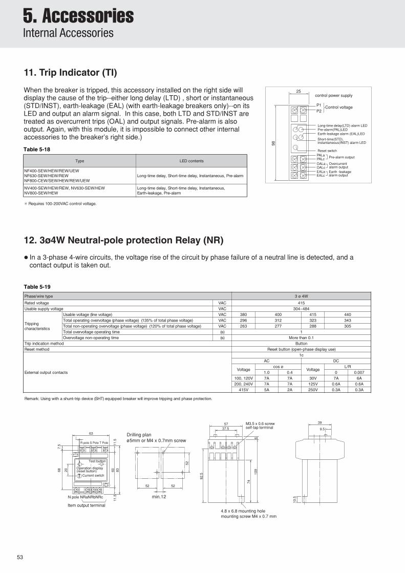
11. Trip Indicator (TI)
When the breaker is tripped, this accessory installed on the right side willdisplay the cause of the trip--either long delay (LTD) , short or instantaneous(STD/INST), earth-leakage (EAL) (with earth-leakage breakers only)--on itsLED and output an alarm signal. In this case, both LTD and STD/INST aretreated as overcurrent trips (OAL) and output signals. Pre-alarm is alsooutput. Again, with this module, it is impossible to connect other internalaccessories to the breaker’s right side.)
Notes: (1) This hole is not required for two and three poles.(2) The last letter of “F” of the type designations of V-type operating handles denotes a fixed type.
Remark: (1) You may contact us for details of the V-type operating handle for the U series.
3P
3P
2P, 3P
2P, 3P
105
105
140
1402P, 3P
2P, 3P
–
15
–
–12.5
–12.5
15
–
17.5
–
17.5
–
17.5
–
17.5
4P
4P
3P
3P
4P
4P
4P
4P
4P
4P
✽Equipped with cylinder key (option) to prevent deliberate operation.
epyTepytsrekaerB .giF )mm(snoisnemiD
BCCM BCLE weivtuO gnillirDnalp A B C D E F G H J K L M P
● This handle in conjunction with the breaker enables the isolation function effective.
● The standard model is equipped with a safety device that prevents the circuit breaker from being turned on if the door is open. (If not desired, please specify so.)
● The handle can be locked at either ON or OFF position. (Three padlocks (35mm, 40mm) can be installed. OFF-position lock only specifications are also acceptable.)
● Degrees of protection (IEC60529) IP3X(IP5X with dustproof packing)
● Includes as standard a safety device which prevents breaker closing as long as the cover is open. (Specify if this safety feature is not required.)
● Indicates the tripping of the breaker even in ON-lock position--but only in cases when a single padlock (35mm, 40mm) is used.
● Degrees of protection (in accordance with IEC60529): IP3X (IP5X with dustproof packing).
Left hinge Right hinge
H X1 H X 2
0or more
(5H+100)or more
Less than 10
10or more
170or more
(5H+120)or more
Table 5-22: Summary of Dimensions
● Drilling plan
Type name Applicable modelsNumberof poles
Dimensions (mm) Mounting screwsA B C D
F05SW2P NF32-SW, NF63-CW/SW/HW 2P
105
–
111
111
EitherM4×0.7
screw or ø5
(a) Circuit breaker
mounting screws(2pcs)
(b) Handle mounting screws
(2pcs)
F05SW3P, 4P
25NV63-CW/SW 3P
F1SW2P NF125-CW/SW/HW 2P –F1SW 3P, 4P 30
F2SW 2P, 3P, 4P 107 35 126F2GSW
F05SWR2P
F05SWR
F1SWR2PF1SWR
F2SWRF2GSWR 3P, 4P 125 35 126
Remark: (1) Trip action can be displayed when the circuitbreaker trips even if ON-position lock is selected(only in the case of a single padlock (35 mm)).
Remarks: (1) The test button becomes difficult to press when an operating handle is installed on an NV model. Then, use models with either TBM instead. (2) Dustproof packings are separately available.(3) You may consult us for details of the F-type operating handle for the U series.
*1. Handles with NV in the product name include a test button.*2. Dustproof packing is also available as an option.*3. Other optional handles can also be mounted.*4. F4SW~F8UW are for isolation purposes. (Speify OFF lock only.)
*5. The figures show the dimensions of the front connection. Some connection and plug-in breakers have a different reference surface for mounting purposes.
*6. The standard type is equipped with a door-lock mechanism that allows the door to be opened only when OFF operation is carried out.
*7. In case of reset opened type use.
*1. Dimensions of both front connection and rear connection are shown. The plug-in type has a different reference plane for mounting the circuit breaker.*2. The standard type is epuipped with a door-lock mechanism that allows door to be opened only when OFF operation is carried out.*3. In case of reset opened type use.
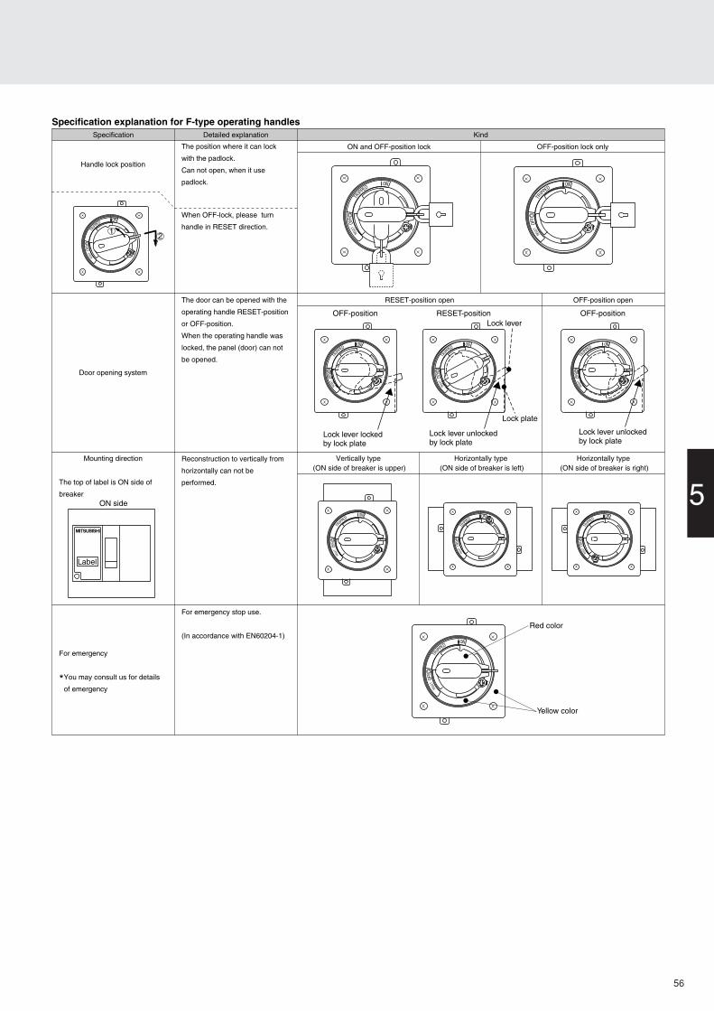
Specification explanation for F-type operating handlesSpecification Detailed explanation Kind
ON and OFF-position lock OFF-position lock only
RESET-position open OFF-position open
Vertically type (ON side of breaker is upper)
Horizontally type (ON side of breaker is left)
Horizontally type (ON side of breaker is right)
Handle lock position
Mounting direction
The top of label is ON side of
breaker
For emergency
*You may consult us for details
of emergency
The position where it can lock
with the padlock.
Can not open, when it use
padlock.
When OFF-lock, please turn
handle in RESET direction.
The door can be opened with the
operating handle RESET-position
or OFF-position.
When the operating handle was
locked, the panel (door) can not
be opened.
Door opening system
Reconstruction to vertically from
horizontally can not be
performed.
For emergency stop use.
(In accordance with EN60204-1)
SE ERT
OF F
TRIPPED
ON
SE ERT
OF F
TRIPPED
ON
SE ERT
OF F
TRIPPED
ON
SE ERT
OF F
TRIPPED
ON
SE ERT
OF F
TRIPPED
ON
SE ERT
OF F
TRIPPED
ON
SE ERT
OF F
TRIPPED
ON
SE ERT
OF F
TRIPPED
ON
SE ERT
OF F
TRIPPED
ON
SE ERT
OF F
TRIPPED
ON
Red color
Yellow color
12
Lock lever lockedby lock plate
OFF-position OFF-positionRESET-position
Lock lever unlockedby lock plate
Lock plate
Lock lever
Lock lever unlockedby lock plate
ON side
Label
56
5. AccessoriesExternal Accessories
Table 5-25
–
–
– –
–
–
● External dimensions ● Drilling plan
5947
Operating plate
Operatingplate
max
. 145
114
130(
S4C
P·S
4SP
)18
0(S
100)
55
110
max
. 150
OF
F
TRIPON
Front panel
Decorative plate
(a)
84
25 102 ± 5
45
12
B ±
2A
± 2
D
35 ±
5
62
5.54-
Retainer
Front panelDeviation: 5mm or less110 or more (250 or more if hingeis mounted on the left)
Deviation: 2 mm or less
Centre of breaker
Hinge
Retainer(option)
Retainer*1
Center of breaker's handle
*1
*2
*5
*3
*3
84Front panel applicable thickness : 1.6 to 3.2
Reference planefor mounting the breaker
(b)
● Outside Dimension Diagram ● Front Plate Drilling Dimension Diagram
Operating plate
ON
OF
F
TRIP
45
110
114
80
Operating plateFront plate
Max
. 95
Max
. 115
34 40
Face plateø62
4-ø4.5 Center of the circuitbreaker
Deviationof 4mmor less
9
70
4770
Clasp(Note 1)
Clasp(Note 1)(Note 2)
Clasp(option)
(Not
e 3)
41.5±
4
(Note 3)43.5±4
Center of the circuit breakeroperating handle
17
Front plate deviation of 4mm or less100 or more (210 or more when the hinge is on the left)
Hinge
A±
2B±
2(N
ote
2) C±
2
Reference plane for mountingthe circuit breaker
ø12
Front plate thickness 1.2–3.2
ON
OFF
Fastening
Fastening ON
OFF
A16
B
M5 screwfor attachingthe fastening
Center ofthe breaker
Center of thehandle of breaker Breaker
Notes: (1) The clasps are not supplied standardly, and should be prepared by users Details on dimensions and others will be available upon request. (2) When the optional clasp is used. (3) The tolerance from the center of ø62 is shown. (4) The dimensions of the front-face type are shown. Some of the back-face and plug-in types have a different reference plane for mounting the circuit breaker. (5) The front plate drilling dimensions for the U series differ from those shown above. Please consult us for their details.
Notes: *1. Retainers are not included. They must be provided by the customer.*2. When using optional retainer.*3. Shows the tolerance for the distance from the center of a 62mm dia. hole.*4. The figures show the front-connection dimensions. Some rear-connection and plug-in breakers have a different reference surface for mounting purposes.*5. S4CW and S4SW are for isolation purposes. (Specify OFF lock only.) The tolerance is less than 5mm. It does not conform to isolation purposes, however, if the deviation is more than 2mm.
Remark: The clamp for surface plate interlock fastener is common to 2P, 3P and 4P.
epyT epytrekaerBgiF )mm(snoisnemiD
lanretxEsnoisnemid nalpgnillirD A✳4 B✳4 C✳4 D
W *5C4S NF400-CW, NV400-CW a b 041 651 —
NF400-SW/SEW/HEW/REW, NV400-SW/SEW/HEW/REWNF630-CW/SW/SEW/HEW/REW, NV630-CW/SW/SEW/HEWNF800-CEW/SDW/SEW/HEW/REW, NV800-SEW/HEW a b
● The handle can be locked at either ON or OFF position. (Three padlocks (35mm, 40mm) can be installed. Off-position lock only specifications are also acceptable.)
● Digrees of protection (IEC60529) IP5X
● Indicates the tripping of the breaker even in ON-lock position--but only in cases when a single padlock(35mm or 40mm) is used.
● Degrees of protection (in accordance with IEC60529): IP5X.
Remark: (1) Trip action can be displayed when the circuitbreaker trips even if ON-position lock is selected(only in the case of a single padlock (35 mm)).
Remark: (1) Reset open-type(2) These are not suitable for isolation.
Operationhandle series Type Drilling diagram and referential diagram
ON/OFF position lockOFF position lock onlyOFF position openRESET position openVertically type (ON side of breaker is upper)Horizontally type (ON side of breaker is left)Horizontally type (ON side of breaker is right)3 pole and 4 pole2 poleNV type for 400 to 800 A frameThe other
SW indicate WSSUW indicate WSS
C, S and H seriesU series
S1)
12)
SW3)
A4)
1) S : Operating handle type2) 1 : Frame size of breaker
Notes: (1) Attach the letter “F” to the end of model designation for models with F-type operating handle. (Those are F-type operating-handle dedicated models,and screws are used for fixing.)
(2) An F-type operating handle can be installed standardly.Remarks: (1) Parenthesized numbers denote the outside dimensions (A×B×C in mm).
(2) The terminal cover for a four-pole model can be produced upon request.
A(.mmnisnoisnemidlanretxeswohS)(.1:skrameR ✕B✕ )C✳ edisdaoL/ediseniL.1✳ .epytni-gulpnodetnuomebnacsrevocesehT.2✳ Except for NF400/630-HEW/REW and NV400/630-HEW/REW..3
NF800-SEW/HEW 2.giF
1.giF
W4S4-LCT042( ✕104.5✕110)
W3S8-LCT422( ✕103.5✕155)
W3U8-LCT ✳1022( ✕ 5.491/641 ✕ )551
W4S8-LCT492( ✕103.5✕155)
W4U8-LCT ✳1092( ✕ 5.491/641 ✕ )551
TCL-10SW3022( ✕ 0)51✕931
TCL-10SW4092( ✕ 0)51✕931
60
5. AccessoriesExternal Accessories
L2
ALc
X
This refers to the status in which the circuit breaker and the electrical operation device is OFF.
MDS Module MDS Base
ON
OFF(RESET)
P1
P2
S1
S2
S4
P.SPowerSupply
UcM
K1
K2
K3
K1K1
K2
K2K3
K3SW1
SW2
Control circuitvoltage
ALa
Breaker alarm switch (AL)(for small current)
L1
SW1
SW2
M
Switching power supply(except for 24VDC model)
MANUAL/AUTO switch
Limit switch (for spring condition detection Charge/Discharge)
Motor
P.S
Relay(for Charge/OFF operation)
Relay(for motor)
Relay(for motor)
K1
K2
K3
Pumping prevention circuitX
Power LED indicator (red)L1
Trip LED indicator (yellow)L2
SW1
SW2
M
Switching power supply(except for 24VDC model)
MANUAL/AUTO switch
Limit switch (for spring condition detection Charge/Discharge)
Motor
P.S
Relay(for Charge/OFF operation)
Relay(for motor)
Relay(for motor)
K1
K2
K3
Pumping prevention circuitX
X
Breaker is OFF condition and MDS is charge condition
MDS Module MDS Base
ON
OFF(RESET)
P1
P2
S1
S2
S4
P.SPowerSupply
UcM
K1
K2
K3
K1K1
K2
K2K3
K3SW1
SW2
Control circuitvoltage
6. Electrical Operation DeviceTable 5-30: Summary of Model Designations
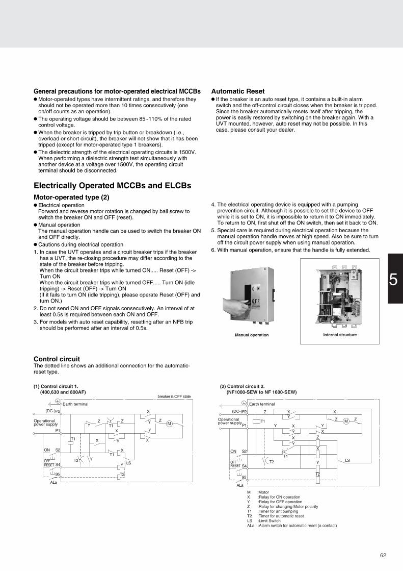
General precautions for motor-operated electrical MCCBs● Motor-operated types have intermittent ratings, and therefore they
should not be operated more than 10 times consecutively (one on/off counts as an operation).
● The operating voltage should be between 85~110% of the rated control voltage.
● When the breaker is tripped by trip button or breakdown (i.e., overload or short circuit), the breaker will not show that it has been tripped (except for motor-operated type 1 breakers).
● The dielectric strength of the electrical operating circuits is 1500V. When performing a dielectric strength test simultaneously with another device at a voltage over 1500V, the operating circuit terminal should be disconnected.
Automatic Reset● If the breaker is an auto reset type, it contains a built-in alarm
switch and the off-control circuit closes when the breaker is tripped. Since the breaker automatically resets itself after tripping, the power is easily restored by switching on the breaker again. With a UVT mounted, however, auto reset may not be possible. In this case, please consult your dealer.
Motor-operated type (2)● Electrical operation Forward and reverse motor rotation is changed by ball screw to
switch the breaker ON and OFF (reset).● Manual operation The manual operation handle can be used to switch the breaker ON
and OFF directly.● Cautions during electrical operation1. In case the UVT operates and a circuit breaker trips if the breaker
has a UVT, the re-closing procedure may differ according to the state of the breaker before tripping.When the circuit breaker trips while turned ON..... Reset (OFF) -> Turn ONWhen the circuit breaker trips while turned OFF..... Turn ON (idle tripping) -> Reset (OFF) -> Turn ON (If it fails to turn ON (idle tripping), please operate Reset (OFF) and turn ON.)
2. Do not send ON and OFF signals consecutively. An interval of at least 0.5s is required between each ON and OFF.
3. For models with auto reset capability, resetting after an NFB trip should be performed after an interval of 0.5s.
4. The electrical operating device is equipped with a pumping prevention circuit. Although it is possible to set the device to OFF while it is set to ON, it is impossible to return it to ON immediately. To return to ON, first shut off the ON switch, then set it back to ON.
5. Special care is required during electrical operation because the manual operation handle moves at high speed. Also be sure to turn off the circuit power supply when using manual operation.
6. With manual operation, ensure that the handle is fully extended.
Control circuitThe dotted line shows an additional connection for the automatic-reset type.
Electrically Operated MCCBs and ELCBs
M
Earth terminal
(DC-)P2
P1
S2
S4
95
ON
OFFRESET
Operationalpower supply
ALa
T1
T1
T1T2
LS
T2
YY
Y
Y
Y
YX
X
X
X
X
Z ZZ
breaker is OFF state
M :MotorX :Relay for ON operationY :Relay for OFF operationZ :Relay for changing Motor polarityT1 :Timer for antipumpingT2 :Timer for automatic resetLS :Limit SwitchALa :Alarm switch for automatic reset (a contact)
Earth terminal
(DC-)P2
P1
S2
S4
95
ON
OFFRESET
Operationalpower supply
ALa
T1
T1T2 LS
Y
YX
YX
XY
YX
Z
Z
Z
XZ
M
X
Y
T2
(2) Control circuit 2. (NF1000-SEW to NF 1600-SEW)
(1) Control circuit 1. (400,630 and 800AF)
Manual operation Internal structure
62
5. AccessoriesExternal Accessories
Control circuitThe dotted line shows an additional connection for the automatic-reset type.
Spring-charged type● Electrical operation When the ON switch is closed, the coil is excited to release the
latch mechanism and the force of the closing spring turns the breaker ON instantly.
When the OFF switch is closed, a relay starts the motor which turns the breaker OFF and charges the spring simultaneously.
● Manual operation Pressing the ON button will release the latch mechanism and the
force of the closing spring turns the breaker ON instantly. Pressing the leaf spring, pulling out the manual handle and pumping
it back and forth over 10 times will turn the breaker OFF and charge the spring at the same time.
● Cautions during electrical operation Whenever an electrical operation device is to be installed in or
removed from the breaker, the breaker must be tripped and the device discharged.
Pushing the TRIP button on an MCCB with an electrical-operation device installed will not trip the breaker in the OFF state. This does not mean the breaker is faulty.
Switching OFF a breaker with an electrical-operation device installed will take 3s. If instant opening is required, install an SHT or UVT to the breaker.
● The breaker contains a built-in pumping-prevention relay.
Internal connection
Earth terminal
(DC-) P2
P1
X
X
M
X
Y Y
YCC
LS1
LS2
LS3
S2
S4
ON
OFFRESET
Operationalpower supply
Alarm switch for automatic resetting (contact a)
CC.....Coil for makingY.....Relay for pumping preventionX.....Relay for self-sustaining on OFF sideLS1...Limit switch interlocking with camLS2...Limit switch interlocking with camLS3...Limit switch interlocking with OFF lock plateM....Motor
Ala
Internal structure
63
5
max. 19
8
110–
111
30 30
S4S2S1P2P1S4S2S1P2P1
40
80
8825
4586
3941
163158
24
61
78
86
130
50
120
30
9090
111
8660
90 Display hole(Charge/Discharge)
M4x0.7 screwor ø5
4-pole3-pole
Circuit breaker
Front plate
Power supply module
Operating circuitterminal board(M3.5 screw)
M8 screw
Display hole(ON/OFF/TRIP)
OFF lock plateInsulation barrier(removable)
Trip button
ON button
Automatic/manualselectionswitch
Manual handle
(Conductor thickness t=5 max.)
ø8.5
Conductor drilling for direct connection
Drilling plan Font-plate cut out
Operating circuitterminal cover(standard supply)
Center of the electrically operated
Center of the electrically operated
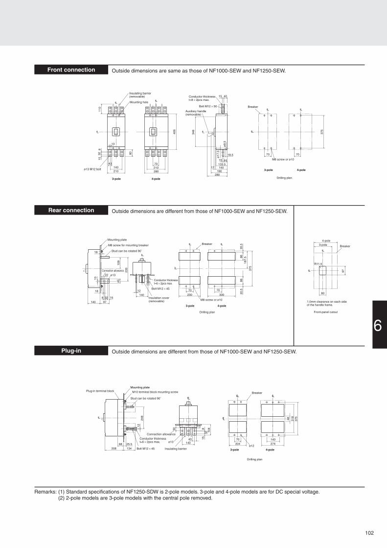
Remarks:The 2-pole models are 3-pole models with the central pole removed.The three-pole type only is available for the model NF125-CW, and the3-pole and 4-pole types only are available for the model NF125-SW.
With two breakers, use a panel-mounted mechanical interlock for one-way only input.A breaker-mounting mechanical to mount on the breaker main unit can be made to order. Consult your dealer for more details.
69
5
CL
6
M4×0.7 screw
35
13
7
CLCL
Mounting hookfor IEC 35mm rail
Fig.2Fig.1 Fig.3
4
5
35
Adapter for IEC 35mm rail
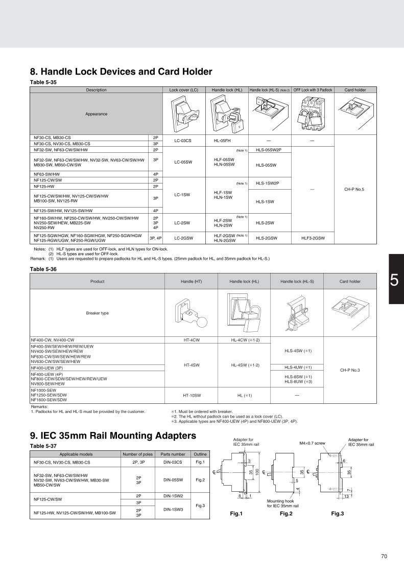
8. Handle Lock Devices and Card HolderTable 5-35
Table 5-36
9. IEC 35mm Rail Mounting AdaptersTable 5-37
Notes: (1) HLF types are used for OFF-lock, and HLN types for ON-lock.(2) HL-S types are used for OFF-lock.
Remark: (1) Users are requested to prepare padlocks for HL and HL-S types. (25mm padlock for HL, and 35mm padlock for HL-S.)
Applicable models Number of poles Parts number Outline
:skrameR.remotsucehtybdedivorpebtsumS-LHdnaLHrofskcoldaP.1 ✳1. Must be ordered with breaker.
✳2. The HL without padlock can be used as a lock cover (LC). ✳3. Applicable types are NF400-UEW (4P) and NF800-UEW (3P, 4P).
—
W (✳1·2)
W (✳1)
HL (✳1)
W (✳1·2) W (✳1)
CH-P No.5
8
100
35
1
3
Adapter for IEC 35mm rail
3.oNP-HC
70
71
2-pole
3-pole
ALLeft-sidemounting
Right-sidemounting
Operating handle
AXLead wiredirection
NF30-CSMB30-CS
Type NF30-CS
■Operating Characteristics
■Internal Accessories
■External Accessories
■Temperature Characteristics
Note: (*1) The designation depends on the number of poles. Refer to the reference page.
Remark: (1) Standard lead wire is drawn from side. However, lead wire drawn by load can beproduced upon request.
(2) refer to page 44.
Rate
d sh
ort-c
ircui
t br
eakin
g ca
pacit
y (k
A)
Rated current In (Amp.)
Number of poles 32
IEC 60947-2(Icu/Ics) AC
Rated insulation voltage Ui (V) 500
—
—
1.5/1.5
1.5/1.5
2.5/2
Type name NF30-CS
Frame size 30
Series C series
3, 5, 10, 15, 20, 30
690V
500V
415V
380V
240V
32 (for single phase)
MB30-CS
(2), (3.2), 4, (5),6.3, (8), 10, 16
1.4, 2.5, 4, 7.1,10, 16, 25, 32
Max.
Min.
1 1.250.01s
0.02s
0.04s
0.1s
0.2s
0.4s
0.6s
1s
2s
4s
6s
10s
20s
30s40s
1min
2min
4min
6min
10min
20min
40min
1h
2h
3h
0.06s
2 3 4 5 7 10 20 30 40 50 70 100
Ope
ratin
g tim
e
×100% of rated current
Rate
d am
bien
t
Ambient temperature (°C)
Ope
ratin
g tim
ech
ange
rat
e (%
) 300250
200
150
100
8070
6050403020100
300250
200
150
100
8070
6050403020100–10
Standard Attached Parts (Front connection)
Mounting screw: M4×0.7×20 (2pcs)Small terminal cover 2pcs Only MB30-CS
TypesNF30-CSMB30-CS
60
70
70
70
Term
inal
cov
er Small
Large
Rear
Skeleton
TCS-03CS3W (*1)
TCL-03CS3W (*1)
BTC-03CS3W (*1)
TTC-03CS (*1)
HL-05FH
LC03CS
DIN-03CS
(TC-S)
(TC-L)
(BTC)
(TTC)
(HL)
(LC)
(DIN)
Handle lock
Lock cover
Rail mounting adapters
Accessories Type name Referencepage
6. Characteristics and DimensionsMolded-Case Circuit Breakers and Motor Breakers
6
72
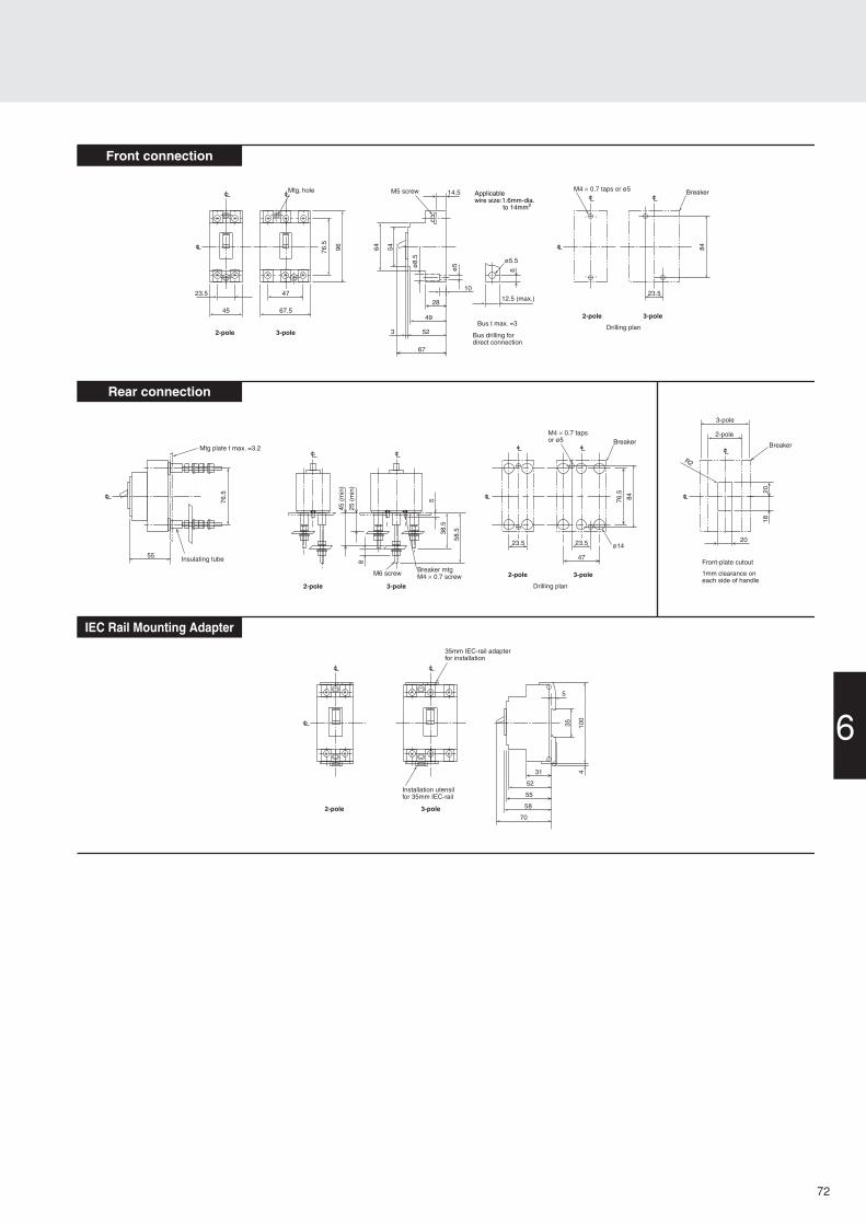
Front connection
Rear connection
IEC Rail Mounting Adapter
4723.5
67.545
64 54
ø8.
5
10
14.5
12.5 (max.)
76.5
96
Mtg. hole M5 screw
Bus t max. =3
Bus drilling fordirect connection
2-pole 3-pole
2-pole 3-poleDrilling plan
ø5
28
49
523
67
6
ø5.5
84
23.5
BreakerM4 × 0.7 taps or ø5
2-pole 3-pole
2-pole 3-pole Drilling plan
8476.5
23.5
Breaker
ø14
M4 × 0.7 tapsor ø5
76.5
Mtg plate t max. =3.2
Insulating tube
5
38.5
58.5
8
45 (
min
)
25 (
min
)
Breaker mtgM4 × 0.7 screwM6 screw
47
23.5
Front-plate cutout
1mm clearance oneach side of handle
Breaker
R2
3-pole
2-pole
2018
20
55
35 100
431
52
55
58
70
35mm IEC-rail adapterfor installation
Installation utensilfor 35mm IEC-rail
2-pole 3-pole
5
Applicablewire size:1.6mm-dia. to 14mm2
73
6. Characteristics and DimensionsMolded-Case Circuit Breakers and Motor Breakers
2-pole
3-pole
AL
Left-sidemounting
Right-sidemounting
Breaker handle
AX
SHT or UVT
Lead wiredirection
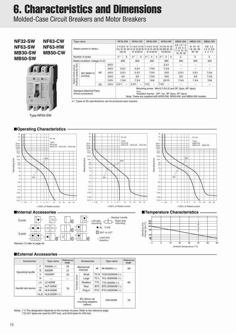
Type nameType name
F05SW (*1)F 55
57
54
Ml Ml-05SW3 (*1) 69S S05SW
V V05SWF
R
Small TC-S TCS-05SW3W (*1)
60
70
Large TC-L TCL-05SW3W (*1)
Skeleton TTC TTC-05SW3 (*1)
Rear BTC BTC-05SW3W (*1)
LC LC-05SW
Plug-in PTC PTC-05SW3W (*1)(*2)HL HLN-05SW
HLF-05SW
DIN-05SW 70
HL-S HLS-05SW (*1)
NF32-SWNF63-SWMB30-SWMB50-SW
■Operating Characteristics
■Internal Accessories
■External Accessories
■Temperature Characteristics
Notes: (*1) The designation depends on the number of poles. Refer to the reference page.(*2) HLF types are used for OFF-lock, and HLN types for ON-lock.
Remark: (1) refer to page 44.
Note: These are supplied with NF63-SW, NF63-HW, and MB50-SW models.
Notes: (*1) The designation depends on the number of poles. Refer to the reference page.(*2) Attach the letter "F" to the end of designation for a fixed type.(*3) Specify the working voltage. An order should be placed at the same time as an order of circuit breaker main body.(*4) HLF and HLS types are used for OFF-lock, and HLN types for ON-lock.
Remark: (1) refer to page 44.
AC
DC
Min.
breaking time
Max. total
Max.
NF125-HW 32A
TyepsMB100-SW 32ANF125-SW 32A
Time-delay trip Instantaneous trip
DC
AC
Min.
breaking timeMax. total
MB100-SW 12.5A~25ANF125-HW 16A~20A
TyepsNF125-SW 16A~20A
Max.
Instantaneous tripTime-delay trip
Type NF125-SW
Note: These are supplied with NF125-SW, NF125-HW, and MB100-SW models.
6. Characteristics and DimensionsMolded-Case Circuit Breakers and Motor Breakers
6
76
Front connection
Rear connection
Plug-in
M5×0.8Terminal blockmounting screw
4-pole
4-pole
2-pole 3-pole2-pole
3-pole
Drilling plan
Plug-in terminal block
Mounting plateBreaker (plug-in terminal block)
6mm-dia. holeor M5×0.8 taps
Details of terminal
M8 screw
Conductor drillingfor direct connection
134
φ8.5
12
16.5 max.
65
30
90
125
60
95
205.5
30
21
11
190
98
67 97
30 60
127
5656
9454
30
12.5
LCLCCL
LC
89
LC
R1
R1
2-pole
Breaker
52
86
3-pole
28
4-pole
57
Front-panel cutout
1.0mm clearance on each sideof the handle frame.
CL
CL
LC
LC
Mounting base
4-pole
30
112
30
90
2-pole
8
3-pole
4-pole
102
52
15
72
68
8.5
2.5
15
54.5
104.5
15
2.5
16
112
60
90
5
30
60
30
3-pole2-pole
M4×0.7 taps or5mm-dia. hole
Mounting platet=3.2 max.
Stud rotatableby 90°
Connectionallowance
M8 bolt
Insulationtube
M4×0.7breakermounting screw
Breaker
Drilling plan
φ18
CLCL
CL
CL
LC
4-pole
30
130
112
4-pole
120
90
30
Neutralpole
50
60
30
90
60
22
24
84 50
68
61
45
724
90
φ8.5
8
19 max.
30
3-pole
3-pole
2-pole
2-pole
Tripbutton
Insulation barrier(removable)
Mounting hole
Conductor drillingfor direct connection
(Conductor thickness t=5 max.)
Breaker
Drilling plan
M4X0.7 tapsor 5mm-dia. hole
M8 screw
Solderless terminalfor wire size
14~2/0AWG CU/AL
Wire connection
LC
LC
LC LCLC
LCLC
CL
Note: (*1) It can respond to the attachment size of 110 and 111 both sides.Remark: 2-pole model of NF125-HW are 3-pole model with the central pole removed.
(*1)
110-
111
(*1)
110-
111
77
6. Characteristics and DimensionsMolded-Case Circuit Breakers and Motor Breakers
NF250-CWNF250-HWNF160-HW
NF250-SWNF160-SWMB225-SW
■External Accessories
F F2SW 55
57
54
58
Ml Ml-05SW3 (*1) 69S S2SW
V V2SW (*3)
R R2SW
Small TC-S TCS-2SW3W (*1)
60
61
Large TC-L TCL-2SW3W (*1)
Skeleton TTC TTC-2SW3 (*1)
Rear BTC BTC-2SW3W (*1)
LC LC-2SW
70Plug-in PTC PTC-2SW3W (*1)
(*4)HL
HLF-2SW
MDS-NF2SWE (*2)
HLN-2SW
HL-S HLS-2SW
*1: When wired as shown at the bottom of page 13, 3-pole models can be used for up to 400 V DC, and 4-pole models for up to 500 V DC.
Rat
ed s
hort
-circ
uit
brak
ing
capa
city
(kA
)
Rated current In (Amp.)
Number of poles 2 3 2 3 4
IEC 60947-2(Icu/Ics)
AC
DC
Rated insulation voltage Ui (V) 600
–
10/5
15/8
18/9
35/18
–
Type name NF250-CW
(100)125 150 175200 225 250
690
–
15/8
25/13
30/15
50/25
15/8
NF250-SW
(100)125 150 175200 225 250
690V
500V
440V
400V
230V
250V
400V
500V
10/5 15/8– –
– 10/5 – –
15/8–
2 3 4
690
5/3
30/8
50/13
50/13
100/25
40/20
NF250-HW
125 150 175200 225 250
3
500
–
–
25/13
30/15
50/25
–
–
–
MB225-SW
125 150 175200 225
40/20 –
– –
40/20–
2 3 4
690
5/3
30/8
50/13
50/13
100/25
40/20
NF160-HW
40/20 –
– –
40/20–
2 3 4
690
–
15/8
25/13
30/15
50/25
15/8
NF160-SW
125 150 160 125 150 160
15/8 –
– –
15/8–
■Operating Characteristics
NF160-HWNF160-SWMB225-SW
NF250-HWNF250-SWNF250-CWTypes
time
Max.
Max. total
Instantaneous trip
breaking
Min.
Time-delay trip
×100% of Rated current
Ope
ratin
g tim
e
4h
2h
1h
30min 20min 14min 10min 6min 4min
2min
1min
30s20s
10s
5s
2s
1s
0.5s
0.2s
0.1s
0.05s
0.02s
1 1.25 2 3 4 5 6 7 10 15 20 30 400.01s
Cur
reny
rat
ing
(%)
Rat
ed a
mbi
ent
–10 10 20 30 40 50 6080
90
100
110
120
130
Ambient temperature (°C)(rated ambient 40°C)
0
Ter
min
al c
over
AL AX
■Internal Accessories
Left-sidemounting
Right-sidemounting
Operating handle
SHT or UVT
Lead wiredirection
■Ambient Compensating Curve
Notes: (*1) The designation depends on the number of poles. Refer to the reference page.(*2) Specify the working voltage. An order of MB225-SW should be placed at the same time as an order of circuit breaker main body.(*3) Attach the letter "F" to the end of designation for a fixed type.(*4) HLF types are used for OFF-lock, and HLN types for ON-lock.
Type nameType nameAccessories Accessories
Mechanicalinterlock
Referencepage
Referencepage
Operating handle
Handle lock device
Electricaloperation device
125~225A DC
125~225A AC250A DC
250A AC
Type NF250-SW
Remark: (1) Only AC characteristics are available for the model MB225-SW.(2) refer to page 44.
Remarks: 1. 2-pole models are 3-pole models with the central pole removed.2. Only 2- and 3-pole models are available for the model of NF250-CW, and only 3-pole models are available
∗1: Use either 2-pole. When wired as shown at the bottom of page 13, 3-pole models can be used for up to 500 V DC, and 4-pole models for up to 600V DC.
■Ambient Compensating Curve
Remark: (1) refer to page 44.
Type nameAccessories
Mechanicalinterlock
Referencepage Type nameAccessories Reference
page
Operating handle
Handle lock device
OFF Lock with 3 Padlock HLF3-2GSW Electricaloperation device
Notes:(*1) The designation depends
on the number of poles. Refer to the reference page.
(*2) HLF types are used for OFF-lock, and HLN types for ON-lock.
(*3) Attach the letter “F” to the end of designation for a fixed type.
(*4) Specify the working voltage.
Instantaneous tripcurrent ratio
DC x In (%)
AC x In (%)
1300±2601000±200
AC
DC
16-25A (Rated current In=25A)NF125-SGW/HGW 25-40A (Rated current In=40A)
Min.
breakingMax. total
Max.
time
Thermal-Adjustable types
Time-delay trip Instantaneous trip
AC x In (%)1000±200
Instantaneous tripcurrent ratio
DC x In (%)1300±260
AC
DC
Min.
breakingMax. total
Max.
time
NF125-SGW/HGW 63-100A (Rated current In=100A) 40-63A (Rated current In=63A)
Thermal-Adjustable types
Time-delay trip Instantaneous trip
Instantaneous trip adjustmentrange
Positionof notch
468
10
400±80600800
1000±200
AC x In (%)
520±104
DC x In (%)
78010401300±260
(Adjustable range)
(Adjustable range)DC
AC
NF125-SGW/HGW 80-125A (Rated current In=125A)NF160-SGW/HGW 125-160A (Rated current In=160A)NF250-SGW/HGW 160-250A (Rated current In=250A)
time
Max.
Max. totalbreaking
Min.
Thermal-Adjustable types
Time-delay trip Instantaneous trip
Type NF250-SGW
±15%
STD pickup current IS
STD operating time TS
Ir × (2-2.5-3-3.5-4 -5-6-7-8-10)
(at 200%)
LTD operating time TL
0.06±0.02s0.1±0.03s
0.2±0.04s0.3±0.06s
Pre-alarmpickup current IPIr × (0.70-0.75 -0.8-0.85-0.9 -0.95-1.0) ± 10%
12-60-80-100s ± 20%
Pre-alarm operating time TP
TLTP= 2 ± 20%
(at 200%)
Max.total breaking time
In × (4~14) ±15%INST pickup current Il
0.01s
0.02s
0.05s
0.1s
0.2s
0.5s
1s
2s
5s
10s
20s
1min
30s
2min
4min6min
10min
20min30min
1h
2h
4h
Ope
ratin
g tim
e
0.6 0.7 4020151065 7 3042 31.251
× 100% of Current setting
Note) Instantaneous tripping current (× 100% of In)
NF125-SGW NF125-HGWNote)Current setting Ir Rated current In16~ 32A32~ 63A63~ 100A75~ 125A
32A63A
100A125A
(Adjustable)
Electric types
(at 200%)
± 20%2
TP = TL
Pre-alarm operating time TP
12-60-80-100s ± 20%
Ir × (0.70-0.75 -0.8-0.85-0.9 -0.95-1.0) ± 10%
Pre-alarmpickup current IP
0.3 ± 0.06s0.2 ± 0.04s
0.1 ± 0.03s0.06 ± 0.02s
In × (4~14) ± 15%
LTD operating time TL
(at 200%)
Ir × (2-2.5-3-3.5-4 -5-6-7-8-10) ± 15%
STD operating time TS
INST pickup current Il
STD pickup current IS
Max.total breaking time
Note) Instantaneous tripping current (× 100% of In)
1 1.25 32 4
Ope
ratin
g tim
e
3075 6 10 15 20 400.70.6
NF250-SGW NF250-HGW
Note)Current setting Ir Rated current In 125~250A 250A (Adjustable)
Electric types
× 100% of Current setting
4h
2h
1h
30min20min
10min
6min4min
2min
30s
1min
20s
10s
5s
2s
1s
0.5s
0.2s
0.1s
0.05s
0.02s
0.01s
STD pickup current IS
STD operating time TS
Ir × (2-2.5-3-3.5-4 -5-6-7-8-10)±15%
(at 200%)
LTD operating time TL
0.06±0.02s0.1±0.03s
0.2±0.04s0.3±0.06s
Pre-alarmpickup current IPIr × (0.70-0.75 -0.8-0.85-0.9 -0.95-1.0) ±10%
12-60-80-100s ±20%
Pre-alarm operating time TP
TLTP=2
± 20%
(at 200%)
Max.total breaking time
In × (4~14) ±15%INST pickup current Il
Note) Instantaneous tripping current (× 100% of In)
0.01s
0.02s
0.05s
0.1s
0.2s
0.5s
1s
2s
5s
10s
20s
1min
30s
2min
4min6min
10min
20min30min
1h
2h
4h
Ope
ratin
g tim
e
0.6 0.7 4020151065 7 3042 31.251
× 100% of Current setting
Note)Current setting Ir Rated current In80~160A 160A (Adjustable)
6. Characteristics and DimensionsMolded-Case Circuit Breakers
6
80
Front connection
Rear connection
Plug-in
Remark: 2-pole models are 3-pole models with the central pole removed.
Mounting plate
4530Stud can berotated 90°
5454
9466
4-pole
3-pole
110
1048
103
M8 bolt(Hex-soket)12 96
4
4854
.514
4
120
15
200
4-pole3-poleø9 M8bolt
105
142
Drilling plan
Con
nect
ion
al
low
ance
Insulating barrier(removable)
M6Terminal blockmounting screw
Breaker (Terminal block)
φ7
Plug-in terminal block
107
70
70
20
86
3-pole
4-pole
100
52
32.5
Breaker
1mm clearanceon each sideof handle
Front-panel cutout
R1
35
90
86
Breaker
4-pole3-pole
144
126
35
105
35
70
105
6
8
3-pole
4-pole
Insulatingtube
M4×0.7tapsor φ5
Drilling plan
106
71
φ24
M4×0.7breakermountingscrew
φ9M8 bolt
Connectionallowance
Insulating tube
Stud can berotated 90°
Mounting plate t max.=3.2
70
144
2022
15
15
Hex-socket set screwWire connection
Solderless terminalfor wire size2.5 185mm2
10
6.1
2235
24 max.
110
90
86
79
63
112
4-pole3-pole
Neutralpole
4-pole3-pole
144
165
5050
35
105
140
126
35φ8.5
(Hex-soket)
φ4.5
M4×0.7 tapsor φ5
Drilling plan
BreakerM8 bolt
(Bus t max.=7)
Bus drilling fordirect connection
Tripbutton
Mounting hole
Insulating barrier(removable)
φ8.5
10
22
70
24
4
50
105
81
F—
S
V 54
58
69
Small TC-S
60
Large TC-L
Rear BTC
—
Skeleton TTC
Plug-in PTC
LC
(*2)HL
HL-S
MI
70
TCS-2GSW3W (*1)
TCL-2GSW3W (*1)
BTC-2GSW3W (*1)
PTC-2GSW3W (*1)
TTC-2GSW3 (*1)
LC-2GSW
HLN-2GSW
HLF-2GSW
HLS-2GSW
V2GUW
R R2GUW
—
—
—
MI-05SW3 (*1)
AL AX
NF250-RGWNF125-RGW
NF250-UGWNF125-UGW
Rat
ed s
hort
-circ
uit
brak
ing
capa
city
(kA
)
Rated current In (Amp.)
Number of poles
IEC 60947-2(Icu/Ics)
AC
DC
Rated insulation voltage Ui (V)
Type name
32
690
25/25
125/125
125/125
125/125
125/125
–
–
–
NF125-RGWRT
16–25 25–4040–63 63–100
16–25 25–4040–63 63–100
32 2 3 4
690
25/25
125/125
125/125
125/125
125/125
–
–
–
690
30/30
200/200
200/200
200/200
200/200
–
–
–
NF250-RGWRT
NF250-UGWRT
125–160160–225
125–160160–225
2 3 4
690
30/30
200/200
200/200
200/200
200/200
–
–
–
NF125-UGWRT
690V
500V
440V
400V
230V
300V
500V
600V
■Operating Characteristics
■Internal Accessories
■External Accessories
Ter
min
al c
over
Left-sidemounting
Right-sidemounting
Operating handle
SHT or UVT
Remark: (1) refer to page 44.
Type name Type nameAccessories AccessoriesReferencepage
Referencepage
Operating handle
Mechanical interlock
Electrical operation device
Handle lockdevice
Notes: (*1) The designation depends on the number of poles. Refer to the reference page.(*2) HLF and HLS types are used for OFF-lock, and HLN types for ON-lock.
■Ambient Compensating Curve
×100% of Rated current
Ope
ratin
g tim
e
4h
2h
1h
30min 20min 14min 10min
6min 4min
2min
1min
30s20s
10s
5s
2s
1s
0.5s
0.2s
0.1s
0.05s
0.02s
1 1.25 2 3 4 5 6 7 10 15 20 30 400.01s
×100% of Rated current ×100% of Rated current
Ope
ratin
g tim
e
4h
2h
1h
30min 20min 14min 10min
6min 4min
2min
1min
30s20s
10s
5s
2s
1s
0.5s
0.2s
0.1s
0.05s
0.02s
1 1.25 2 3 4 5 6 7 10 15 20 30 400.01s
Ope
ratin
g tim
e
4h
2h
1h
30min 20min 14min 10min
6min 4min
2min
1min
30s20s
10s
5s
2s
1s
0.5s
0.2s
0.1s
0.05s
0.02s
1 1.25 2 3 4 5 6 7 10 15 20 30 400.01s
AC x In (%)
1000±200800600400±80
10864
Positionof notch
Instantaneous trip adjustment range
Min.
breakingMax. total
Max.
time
NF250-RGW/UGW 160-225A (Rated current In=225A) 125-160A (Rated current In=160A)
Thermal-Adjustable types
Time-delay trip Instantaneous trip
AC(Adjustable range)
Instantaneous tripcurrent ratio
1000±200
AC x In (%)
40-63A (Rated current In=63A)NF125-RGW/UGW 63-100A (Rated current In=100A)
time
Max.
Max. totalbreaking
Min.
AC
Thermal-Adjustable types
Time-delay trip Instantaneous trip
1000±200
AC x In (%)
Instantaneous tripcurrent ratio
time
Max.
Max. totalbreaking
Min.
NF125-RGW/UGW 25-40A (Rated current In=40A) 16-25A (Rated current In=25A)
Standard Attached Parts(4-pole models are provided with auxiliary handle.)
Time-delay trip Inst trip
Ope
ratin
g tim
e
Min.
Max.
TypeNF800-SDW
0.01s
1min.
1h
0.02s
0.05s
0.1s
0.2s
0.5s
1s
2s
5s
10s
20s30s
2min
4min6min
10min14min20min30min
2h
4h
Max. totalinterrupting time
Inst. trip adjustmentrange (4 steps)
Controlsetting
Inst tripcurrent (A)
Lo23Hi
2600±5203900±7805200±10406500±1300
700A,800ADC
Adjustmentrange700A
Adjustmentrange800A
×100% of rated current
1 1.25 2 3 4 5 6 7 10 15 20 30 40
SHT or UVTAL AXLeft-sidemounting
Right-sidemounting
Operating handleLead wiredirection
Note: (*1) Right-side mounting is standard of SHT and UVT. Specify separately for left-side mounting.Remark: (1) refer to page 45.
(*1) (*1)
(*1)(*1)
6. Characteristics and DimensionsMolded-Case Circuit Breakers
6
96
Front connection
Rear connection
Plug-in
Remarks: (1) Standard specification of NF800-SDW is 2-pole model. 3-pole and 4-pole models are available for DC special voltage.(2) 2-pole models are 3-pole models with the central pole removed.
140210
70
N
210 280
110
14
40
51
32
815
32
275
87
97
103
107
87
32
94.5
8
4626
8
4610
2
15
22
40
ø8.5
5
ø14
155
217
12
70
70
243
243
295
243
70
140
45
25
13
8 15
113 110
14032
10
12.5
70
70
210
105
17251
92
R6
8
208
70
278
140
155
5656
18713
40
140
3225
815
112
243
20
301
126
23
Neutral pole
4-pole3-pole
Trip button
Insulating barrier (removable)Mounting hole
ø14M12 bolt
ø8
Conductor thicknesst=12 max.
Conductor drilling for direct connection
(Conductor thickness t=10 max.)
Auxiliary handle(removable) Terminal dimension for
directly connectingconductor
4-pole
3-pole
Breaker
Drilling plan
M6 tap or ø7
4-pole
3-poleBreaker
Front-panel cutout
1.0mm clearance on eachside of the handle frame.
ø48
4-pole3-pole
M6 tap or ø7
Breaker Groove for reducing heatby overcurrent
Drilling plan
M6 screw formounting breaker
ø13M12 bolt
Mounting plate
Stud can be rotated 90°Connection allowance
Mounting plate
Plug-in terminal block
M8 terminal block mounting screw
Stud can be rotated 90°
Con
nect
ion
allo
wan
ce
ø13M12 bolt
3-pole 4-pole
ø10
Drilling plan
Breaker
2424
2424
11 11
140
70
243
6-ø48
510
Boring dimensions for rear connection type barriers (3-pole)
4-M6 tap or ø7
8-M4 screwAdd these tapped holes in 8 positions to standard boring.
Remarks: (1) Standard specifications of NF1250-SDW is 2-pole models. 3-pole and 4-pole models are for DC special voltage.(2) 2-pole models are 3-pole models with the central pole removed.
Outside dimensions are same as those of NF1000-SEW and NF1250-SEW.
Outside dimensions are different from those of NF1000-SEW and NF1250-SEW.
Outside dimensions are different from those of NF1000-SEW and NF1250-SEW.
103
NF1600-SEW
■Operating Characteristics
■Internal Accessories ■Current reducing curve
Type name
Rated current In (Amp.)
Number of poles
Reted insulation voltage Ui (V)
Rat
ed s
hort-
circ
uit
brea
king
capa
city
(kA)
690
25/13
65/33
85/43
85/43
125/63
3 4
IEC 60947-2
(Icu/Ics)AC
690V
500V
440V
400V
230V
NF1600-SEW
Adjustable800–1600
Type NF1600-SEW
Note: (*1) The designation depends on the number of poles. Refer to the reference page.
■External Accessories(An order for should be placed at the same time as an order of circuit breaker main body.)
Accessories
Operating handleF
S
55
57
69
70
61
F10SW (*1)
S10SW
MI-16SW3 (*1)
Auxiliary handle
Handle lock
Electrical operation device
HT-10SW
(MI)
(HL)
Mechanical interlock
Type name Referencepage Accessories Type name Reference
Outside dimensions are same as those of NF1600-SEW.
Outside dimensions are different from those of NF1600-SEW.
Remarks: (1) Standard specification of NF1600-SDW is 2-pole model. 3-pole and 4-pole models are for DC special voltage.(2) 2-pole models are 3-pole models with the central pole removed.
107
6. Characteristics and DimensionsEarth-Leakage Circuit Breakers
500100 10005025
NV30-CS
■Operating Characteristics
■Internal Accessories
■Earth-Leakage Tripping Characteristics
■Temperature Characteristics
Remark: (1) Standard lead wire is drawn from side. However, lead wire drawn by load can be producedupon request.
(2) refer to page 44.
■External Accessories
Term
inal
cov
er
Accessories
70
70
7060
(LC) (TC-S)
(TC-L)
(BTC)
(TTC)
Lock cover
Rail mounting adapter
Handle lock device
LC03CS
DIN-03CS
HL-05FH
TCS-03CS3W
TCL-03CS3W
BTC-03CS
TTC-03CS
Small
Large
Rear
Skeleton
Type name Referencepage Accessories Type name Reference
Notes: (*1) Attach the letter "F" to the end of designation for a fixed type.(*2) HLF and HLS types are used for OFF-lock, and HLN types for ON-lock.(*3) Specify the working voltage. (*4) The designation depends on the number of poles. Refer to the reference page.
■Earth-Leakage Tripping Characteristics
0.45s(MAX)Time-delay type
1s(MAX)Time-delay type
2s(MAX)Time-delay type
Ope
ratin
g tim
e
Ground-fault current (% of rated current sensitivity)
50 100010025 50050 100010025 50050 100010025 500
nonoperating timeInertial
nonoperating timeInertial
nonoperating timeInertial
Rate
d no
nope
ratin
g cu
rrent
Rate
d no
nope
ratin
g cu
rrent
Rate
d no
nope
ratin
g cu
rrent
Rate
d cu
rrent
sen
sitivi
ty
Rate
d cu
rrent
sen
sitivi
ty
Rate
d cu
rrent
sen
sitivi
ty
Instantaneous tripTime-delay trip
Max. totalbreaking time
TypesNV125-SW 32ANV125-HW 32A
Max.
Min.O
pera
ting
time
30s20s
10s
5s
0.01s
0.02s
0.05s
0.1s
0.2s
0.5s
1s
2s
1min
2min
4min6min
4h
2h
1h
30min20min14min10min
Max.
Min.
timebreakingMax. total
NV125-HW 16A~20ANV125-SW 16A~20ATypes
Instantaneous tripTime-delay trip
Type NV125-SW
Remark: In case of the CE marking, Internal wiring diagrams differ.
Notes: (*1) Attach the letter "F" to the end of designation for a fixed type.(*2) HLF types are used for OFF-lock, and HLN types for ON-lock.(*3) The designation depends on the number of poles. Refer to the reference page.(*4) Specify the working voltage. (*5) NV250-HW model cannot be produced.
Type NV250-SW
Time-delay trip
Min.
Max.totalbreaking time
Instantaneous trip
NV250-CWTypes
NV250-SWNV250-HW
Max.
250A
125~225A
×100% of rated current
10.01s
0.05s
0.02s
1.3
0.5s
0.2s
0.1s
2s
1s
32 4
Ope
ratin
g tim
e
4min
30s20s
10s
5s
2min
1min
30min20min
6min10min14min
2h
1h
4h
3075 6 10 15 20 40
Time-delay type0.45s(MAX)
Time-delay type1s(MAX)
Time-delay type2s(MAX)
Ope
ratin
g tim
e
Ground-fault current (% of rated current sensitivity)
50 100010025 50050 100010025 50050 100010025 500
Inertialnonoperating timeInertial
nonoperating time
Inertialnonoperating time
Rat
ed n
onop
erat
ing
curr
ent
Rat
ed n
onop
erat
ing
curr
ent
Rat
ed n
onop
erat
ing
curr
ent
Rat
ed c
urre
nt s
ensi
tivity
Rat
ed c
urre
nt s
ensi
tivity
Rat
ed c
urre
nt s
ensi
tivity
Note: (1) Rated operational voltage of time-delay type is for 200-440V.
Notes: (*1) Attach the letter “F” to the end of designation for a fixed type.(*2) HLF types are used for OFF-lock, and HLN types for ON-lock.(*3) The designation depends on the number of poles. Refer to the reference page.(*4) Specify the working voltage. (*5) NV250-HEW model cannot be produced.
■ Internal Wiring Diagram
Characteristicsetting part
Sensitivityselector
Magneticdevice
CT
CT
CT
Leakageindication button
Test button
ZCT
Line
sid
e
Load
sid
e
Magneticdevice
Mechanicalinterlock
Type NV250-SEW
Time-delay type0.45s(MAX)
Time-delay type1s(MAX)
Time-delay type2s(MAX)
Ground-fault current (% of rated current sensitivity)
50 100010025 50050 100010025 50050 100010025 500
Inertialnonoperating timeInertial
nonoperating time
Inertialnonoperating time
Rat
ed n
onop
erat
ing
curr
ent
Rat
ed n
onop
erat
ing
curr
ent
Rat
ed c
urre
nt s
ensi
tivity
Rat
ed c
urre
nt s
ensi
tivity
Rat
ed c
urre
nt s
ensi
tivity
12-60-80-100s ±20%
(at 200%)
±20%2
TP =TL
Pre-alarm operating time TP
Ir ×(0.70-0.75-0.8-0.85-0.9-0.95-1.0) ±10%
Pre-alarmpickup current IP
0.3 ± 0.06s
0.2 ± 0.04s
0.1 ± 0.03s0.06 ± 0.02s
LTD operating time TL
(at 200%)
Ir ×(2-2.5-3-3.5-4-5-6-7-8-10) ±15%
STD operating time Ts
INST pickup current Il
STD pickup current Is
In×(4~16) ±15%
Max.total breaking time
TypesNV250-SEW NV250-HEW
1 1.3 32 4
Ope
ratin
g tim
e
3075 6 10 15 20 400.70.6
×100% of Current setting
Note)Current setting Ir Rated current In125~225A 225A(Adjustable)
0.01s
0.05s
0.02s
0.5s
0.2s
0.1s
2s
1s
4min
30s20s
10s
5s
2min
1min
30min20min
6min10min14min
2h
1h
4h
Note) Instantaneous tripping current (×100% of In)
PAL
Note: (1) Rated operational voltage of time-delay type is for 200-440V.
Ope
ratin
g tim
e
Rat
ed n
onop
erat
ing
curr
ent
Rat
ed c
urre
nt s
ensi
tivity
4h
2h
1h30min
10min
4min
2min1min
30s
10s5s
2s
1s
0.5s
0.2s
0.1s
0.04s0.02s
0.01s
High-speedtype
Rat
ed c
urre
nt s
ensi
tivity
6. Characteristics and DimensionsEarth-Leakage Circuit Breakers
6
116
Front connection
Rear connection
Plug-in
30
125 175A 14 95mm2
200 225A 70 125mm2
Solderless terminalfor wire size
Wire connection
ø8.5
144
165
100
100
35
105
140
126
35
φ8.5 ø4.
5
35
10
23max.
22
70
24
92
4 72
45
68
61
50
102
(upp
er c
over
)
105
Tripbutton
Operatingcharacteristicsselector
Operatingtime selector(for time-delay type)
Sensitivity selector
Leakage indicatorbutton
Insulating barrier(removable)
Mounting hole
Neutralpole
(Hex-soket)
(Bus t max.=7)
Bus drilling fordirect connection
3-pole
M4×0.7 taps or φ5
4-pole
Drilling plan
M8 bolt
3-pole 4-pole
Breaker
Testcover
Test button
Current indication LED OVER PAL 70%
Note: The setting of selector is available by openning the upper cover.
144
126
35
105
35
70
105
6
8
3-pole
4-pole
106
71
72
68
ø24
35
70
144
2022
15
15
Mounting plate t max.=3.2
Insulatingtube Stud can be
rotated 90°
Connectionallowance
φ9M8 bolt
M4×0.7breakermounting screw
Insulatingtube
3-pole
Drilling plan
4-pole
M4×0.7 taps
or φ5
Breaker
3-pole
4-pole
100
52
32.5
Breaker
1mm clearanceon each sideof handle
Front-plate cutoutR1
105
142
54 8058
.558
.5
φ7
22
15
70
107
70
14
6
153
70
20
2834
.514
4
32
18
200
86
Mounting platePlug-in terminalblock
M6Terminal blockmounting screw
Con
nect
ion
allo
wan
ce
Stud attachable in thisderection only
Insulating barrier
φ9M8 bolt
Breaker (Terminal block)
Drilling plan
3-pole 4-pole
117
6. Characteristics and DimensionsEarth-Leakage Circuit Breakers
Notes : (1) The Time-delayed types will be produced when they have the current specifications of 20A or more.(2) Rated operational voltage of time-delay type is for 200-440V.
Rated current In (Amp.) (15) 16 20 (30) 32 4050 (60) 63 (75) 80 100
■Operating Characteristics
Remark: (1) refer to page 44.
■ Internal Wiring Diagram
Type nameAccessories Referencepage
Type nameAccessories Referencepage
Operating handle
Mechanical interlock
Electrical operation device
Handle lockdevice
Notes: (*1) The designation depends on the number of poles. Refer to the reference page.(*2) HLF and HLS types are used for OFF-lock, and HLN types for ON-lock.
Cur
rent
rat
ing
(%)
Rat
ed a
mbi
ent
Ambient temperature (°C)
605040302010080
90
100
110
120
130
–10
Ope
ratin
g tim
e
Ope
ratin
g tim
e
30s20s
10s
5s
0.01s
0.02s
0.05s
0.1s
0.2s
0.5s
1s
2s
1min
2min
4min6min
4h
2h
1h
30min20min14min10min
Ope
ratin
g tim
e
30s20s
10s
5s
0.01s
0.02s
0.05s
0.1s
0.2s
0.5s
1s
2s
1min
2min
4min6min
4h
2h
1h
30min20min14min10min
■Earth-Leakage Tripping Characteristics
Time-delay trip Instantaneous trip
1 2 3 4 5 6 7 10 15 20 30 40 501.3
TypeNV125-RW 40A~100A
Min.
Instantaneous tripTime-delay trip
1 2 3 4 5 6 7 10 15 20 30 40 501.3
TypeNV125-RW 32A
Max.
Min.
×100% of Rated current ×100% of Rated current
Type NV125-RW
Time-delay type0.45s(MAX)
Time-delay type1s(MAX)
Time-delay type2s(MAX)
Ope
ratin
g tim
e
Ground-fault current (% of rated current sensitivity)
50 100010025 50050 100010025 50050 100010025 500
Inertialnonoperating timeInertial
nonoperating time
Inertialnonoperating time
Rat
ed n
onop
erat
ing
curr
ent
Rat
ed n
onop
erat
ing
curr
ent
Rat
ed n
onop
erat
ing
curr
ent
Rat
ed c
urre
nt s
ensi
tivity
Rat
ed c
urre
nt s
ensi
tivity
Rat
ed c
urre
nt s
ensi
tivity
Min.
Max.
TypeNV125-RW 16A~32A
Max. totalbreakingtime
4h
2h
1h
30min20min
10min14min
6min4min
2min
1min
30s20s
10s
5s
2s
1s
0.5s
0.2s
0.1s
0.05s
0.02s
0.01s70601 2 3 4 5 6 7 10 15 20 30 40 501.3
Time-delay trip Instantaneous trip
Max.
Max.(60A~100A)
(40A~50A)
Max. totalbreaking time
Max. totalbreaking time
×100% of Rated current
Remark: In case of the CE marking, Internal wiring diagrams differ.
Rat
ed n
onop
erat
ing
curr
ent
Rat
ed c
urre
nt s
ensi
tivity
4h2h1h
30min
10min
4min2min1min30s
10s5s
2s1s
0.5s
0.2s0.1s
0.04s0.02s0.01s
High-speedtype
6
118
Front connection
Rear connection
Plug-in
Operating timeselector(time-delay type)
Sensitivity currentselector
Test button
Leakageindication button
17319
1
6113
0
3019 max.
171-
172
90
60
22
24
84 5068
61
45
724
90
φ8.5
8
Tripbutton
M4×7 taps or5mm-dia. hole
Mounting hole
(Conductor thickness t=5 max.)
Conductor drilling for direct connection
Breaker
Drilling plan
M8 screw
CL CL
CL LC
171-
172
173
8
M4×7 taps or5mm-dia. hole
30
173
102
52
15
72
68
8.5
2.5
15
54.5
104.5
15
2.5
16
60
5 60
Mounting platet=3.2 max.
Stud rotatbleby 90°
Mounting base
Connectionallowance
M8 bolt
Insulationtube
M4×0.7breakermounting screw
Breaker
Drilling plan
φ18
CL
CL
CL
CL
4.5
52
Front-panel cutout
1.0mm clearance on eachside of the handle frame.
R1
86
BreakerLC
LC
M5×0.8Terminal block mounting screw
6mm-dia. holeor M5×0.8 taps
Drilling plan
Breaker(plug-in terminal block)
Details of terminal Conductor drillingfor direct connection
Plug-in terminalblock
Mounting plate
M8 screw
251
159LC LC
φ8.5
12
16.5 max.205.5
30
21
11
97
30
5656
12.5
LC
60
95
155
115
195 LC
89
CL
(*1)
(*1)
Remark: In case of the CE marking, outside sizes differ.Note: (*1) It can respond to the attachment size of 171 and 172 both sides.
Notes: (*1) The designation depends on the number of poles. Refer to the reference page.(*2) HLF types are used for OFF-lock, and HLN types for ON-lock.
Type NV250-RW
Time-delay type0.45s(MAX)
Time-delay type1s(MAX)
Time-delay type2s(MAX)
Ope
ratin
g tim
e
Ground-fault current (% of rated current sensitivity)
50 100010025 50050 100010025 50050 100010025 500
Inertialnonoperating timeInertial
nonoperating time
Inertialnonoperating time
Rat
ed n
onop
erat
ing
curre
nt
Rat
ed n
onop
erat
ing
curre
nt
Rat
ed n
onop
erat
ing
curre
nt
Rat
ed c
urre
nt s
ensi
tivity
Rat
ed c
urre
nt s
ensi
tivity
Rat
ed c
urre
nt s
ensi
tivity
Note: (1) Rated operational voltage of time-delay type is for 200-440V
Remark: In case of the CE marking, Internal wiring diagrams differ.
Rat
ed n
onop
erat
ing
curre
nt
Rat
ed c
urre
nt s
ensi
tivity
4h2h1h
30min
10min
4min2min1min30s
10s5s
2s1s
0.5s
0.2s0.1s
0.04s0.02s0.01s
High-speedtype
6. Characteristics and DimensionsEarth-Leakage Circuit Breakers
6
120
Front connection
Rear connection
Plug-in
Test button
Leakage indicationbutton
Operating time selector(for time-delay type)
Sensitivity selector
100
100
240
165
75
219
165
75
28
φ8.5
(Bus t max.=7)
Bus drilling fordirect connection
φ8.5
10
23 maxTrip
Button
Mounting holeInsulating barrier(removable)
M8 bolt(Hex-socket)
22
70
105
24
102
50
φ4.5
45
61
68
724
92
M4×0.7 screwor φ5
Drilling plan
Breaker
201
35
125~175A 14~95mm2
200~225A 70~125mm2
Solderless terminalfor wire size
Wire connection
CLC
LC
L
CL
8
72
68
Breaker
Drilling plan
M4×0.7screwor φ5
Insulatingtube
M4×0.7breakermounting screw
φ9M8 bolt
Connection
allowance
Stud can berotated 90°
201
219
35
70
ø24
108
73
219
15
15
22 20
70
6
Mounting platet max.=3.2
Insulatingtube
71
106
LC
CL
CL
CL
11.5
R1
100
Front-plate cutout
1mm clearanceon each sideof handle
Breaker
52
LC
CL
Drilling plan
Con
nect
ion
allo
wan
ce
Breaker (Terminal block)
Insulatingbarrier
φ9M8 bolt
Stud attachable in thisdirection only
M6Terminal blockmounting screw
Plug-in terminalblockMounting plate
70
153
70
15
22
219
275
34.5
86 32
28
6
14
1820
φ770
107
129
155
58.5
58.5
LC
CL
L
L
C
C
Remark: In case of the CE marking, outside sizes differ.
121
6. Characteristics and DimensionsEarth-Leakage Circuit Breakers
Note: (*1) Attach the letter “F” to the end of designation for a fixed type.
Type NF100-SWU
6
134
Front connection
3-pole2-pole
CL
LC
CL CL
30
22
60
Tripbutton
Insulation barrier(removable)
Mountinghole
5084
4 72
61
68
906090
150
50
112
50
45
M8 screw
Conductor drillingfor direct connection
(Conductor thickness t=5 max)
8
φ8.5
19 max.
24
Drilling plan
2-pole 3-pole
R1
52
3-pole
LC
LCCL
2-pole
CLCL LC
110-
111
CL CL
86
30
M4×0.7 taps or5mm-dia. hole
Front-panel cutout
Breaker
30
1.0mm clearance on eachside of the handle frame.
(Line)
(Insulation plate)
Breaker
62
30
57
CAUTION:When mounted in steel or cast boxcover must be insulated as shown.30mm air gap to cover or0.8mm fibre insulating plateextending 12.7mm out fromeach side of breaker.
Hexagon socket set screw
Solderless terminal
5.03
3-pole2-pole
LCLC
CL
14~1/0AWG CU/AL
wire size
LC
(Standard)
(Option)Front connection (Solderless terminal)
135
SHT or UVTAL AX
F F2SWUMl MI-05SWU3
S S2SWU
V V2SWU (*1)Large TC-L TCL-2SWU3
HL HLF-2SWU
■External Accessories
Left-sidemounting
Right-sidemounting
Operating handleLead wiredirection
■Internal Accessories
■Operating Characteristics
NF225-CWU
Rat
ed s
hort
-circ
uit b
reak
ing
capa
citie
s (k
A)
Rated current In (Amp.)at ambient temperature 40°C (IEC30°C)
Note: (*1) Use either two poles. When wired as shown at the bottom of page 26, the models can be used for up to 500 V DC.
(*1)
×100% of Rated current ×100% of Rated current ×100% of Rated current
■Operating Characteristics
■Ambient Compensating Curve
Type nameAccessories Type nameAccessories
Operatinghandle
Handlelock device
Terminalcover
Mechanical interlock
Note: (*1) Attach the letter “F” to the end of designation for a fixed type.
Ope
ratin
g tim
e
30s20s
10s
5s
0.01s
0.02s
0.05s
0.1s
0.2s
0.5s
1s
2s
1min
2min
4min6min
4h
2h
1h
30min20min14min10min
Max. totalbreakingtime
Instantaneous tripTime-delay trip
Max.(40A)
Max.(15A~30A)
Min.
1 4020151065 7 3042 31.35
(60A~150A)
(50A)
Max.(50A)
Max.(60A~150A)
Min.
breaking
Instantaneous tripTime-delay trip
Max. total
time
4020151065 7 3042 31.351
Ope
ratin
g tim
e
30s20s
10s
5s
0.01s
0.02s
0.05s
0.1s
0.2s
0.5s
1s
2s
1min
2min
4min6min
4h
2h
1h
30min20min14min10min
AC x In (%)
1000±200800600400±80
10864
Positionof notch
Instantaneous tripadjustment range
Adjustable rangeMax. totalbreakingtime
Instantaneous tripTime-delay trip
Min.
Max.
4020151065 7 3042 31 1.35
Ope
ratin
g tim
e
30s20s
10s
5s
0.01s
0.02s
0.05s
0.1s
0.2s
0.5s
1s
2s
1min
2min
4min6min
4h
2h
1h
30min20min14min10min
Type NF-SFW
Remark: The reference ambient temperature for IEC models is 30°C.
TypeNF-SFW15A~40A
TypeNF-SFW50A~150A
TypeNF-SJW/HJW125A~250A
6
138
Front connection (Standard)
(Option)Front connection (Solderless terminal)
10
6.1
14AWG-250MCM CU/AL
Front-panel cutout
Breaker
100
52
R1
1.0mm clearance
on each side of
the handle frame.
105
Mounting hole
Trip button
22
70
144
4
50
35
ø8.
5
φ4.5
Hexagon socket set screw
24
105
φ8.5
24 max.
(Conductor thickness t=7max.)
185
83
63
83
86
90
110
79
5018
550
CAUTION:
Insulating barriers must be used
with uninsulated bus bars or
climp on terminals.
27
22
Insulating barrier
(removable)
22
70
144
63
90
110
4
50
35
ø8.
5
φ4.5
126
35
Mounting hole
Trip button
Drilling plan
M4×0.7 taps or
5mm-dia. hole
Breaker
Outline and dimensions (mm (inch))
Type NF-SFW,NF-SJW,NF-HJW
26
62
Insulation plate(Line)
CAUTION:
When mounted in steel or cast box cover
must be insulated as shown.
26mm air gap to cover or extending 12.7mm
out fromeach side of breaker.
Wire size
Hex.socket head
M8 bolt
Bus bar drilling for
direct connection
3-FRONT
4-FRONT
5-RIGHT
112
112
86
LC
LC
LC
LC
LC LC
LCLC
6. Characteristics and DimensionsUL489 Listed Molded-Case Circuit Breakers
139
(*1)
NF-SKW
(*1) (*1)
(*1)
F F4SKW
S S4SKW
V V4SKW (*1)
HL HL-4SP
SHT or UVTAL AXLeft-sidemounting
Right-sidemounting
Operating handleLead wiredirection
■Internal Accessories
■External Accessories
■Operating Characteristics
NF-SKW
Rat
ed s
hort
-circ
uit b
reak
ing
capa
citie
s (k
A)
Rated current In (Amp.)at ambient temperature 40°C
Number of poles 3
IEC 60947-2JIS C 8201-2(Icu/Ics)
UL 489
Rated voltage (AC V)
Rated insulation voltage Ui (V)
600Y/347
20
35
65
690
10/10 (5/5) (*1)
30/30 (25/25) (*1)
42/42 (36/36) (*1)
45/45 (36/36) (*1)
85/85 (65/65) (*1)
Type name NF-SKW
250 300350 400
600Y/347V
480V
240V
AC
690V
500V
440V
400V
230V
AC
■Ambient Compensating Curve
Type nameAccessories Type name
Operating handle
Handle lock device
Note: (*1) Attach the letter “F” to the end of designation for a fixed type.
Type NF-SKW
Notes: (*1) In case of solderless ter minal, interrupting capacity reduces: (/).
Ter minalcover
Large TC-L TCL-4SKW
Note: (*1) Right-side mounting is standard of SHT and UVT. Specify separataly for left-side mounting.
Ope
ratin
g tim
e
30s20s
10s
5s
0.01s
0.02s
0.05s
0.1s
0.2s
0.5s
1s
2s
1min
2min
4min6min
4h
2h
1h
30min20min14min10min
100 4000200015001000600
500 700 3000400200 300135
% of rated current
Time-delay trip Instantaneous trip
Min.
Max.
Max.totalinterrupting time
Type
NF-SKW
80
90
100
110
120
130
Ambient temperature (°C)
(rated ambient 40°C)0 605040302010
Cur
rent
rat
ing
(%)
Rat
ed a
mbi
ent
Accessories
6
140
Front connection
Hexagon socket set screw
CAUTION
7dia. holes or M6 taps
1mm clearance oneach side of handle. Insulating plate
Insulating barrier(removable)
Bus t max.t10
Drilling plan Front-panel cutout
BreakerBreaker
Front connection (Busbar terminal)
250-350MCM CU250A, 300A
250A
350A, 400A
350MCM AL
3/0AWG CU ONLY
UL
Wire size (IEC 60228)
Class 2 Class 5
250A~350A 70~185mm2
400A 150~240mm2
95~185mm2
150~185mm2
IEC
8
97
30
58
Mountinghole
Mountinghole
Tripbutton
Tripbutton
Solderless terminal250~400A
225
257
87
140
(max.141)
140
(max.141)
102
47
103
107
155
5
97
φ7φ12.
5
257
44
13
110
102
47
10
46
97
1075
26
112
φ13
φ12.
5
φ7
46
10
44 118
92194
R6
Tightening torque 275lb-in. (31.1N·m)
Ampere ratings
Ampere ratings
Wire size
Note: Do not remove solderless terminal in any case.Standard attached parts Mounting screw:M6×60 (4pcs), Insulating plate: (1pc)
When mounted in steel or cast box cover must be insulated as shown.58mm air gap to cover or 0.8mm fibre insulating plate extending 12.7mm out from each side of breaker.
Note: Do not remove busbar terminal in any case.Standard attached partsMounting screw:M6×60 (4pcs), Insulating barrier: (4pcs), Insulating plate: (1pc)
(Line)
(Solderless terminal)
103
155
6. Characteristics and DimensionsUL489 Listed Molded-Case Circuit Breakers
141
(*1) (*1)
(*1) (*1)
F F6SLW
S S4SKW
V V6SLW (*1)
HL HL-4SP
SHT or UVTAL AXLeft-sidemounting
Right-sidemounting
Operating handleLead wiredirection
■Internal Accessories
■External Accessories
■Operating Characteristics
NF-SLW
■Ambient Compensating Curve
Type nameAccessories Type nameAccessories
Operating handle
Handle lock device
Ter minalcover
Type NF-SLWR
ated
sho
rt-c
ircui
t bre
akin
gca
paci
ties
(kA
)
Rated current In (Amp.)at ambient temperature 40°C
Number of poles 3
IEC 60947-2JIS C 8201-2(Icu/Ics)
UL 489
Rated voltage (AC V)
Rated insulation voltage Ui (V)
600Y/347
20
35
85
690
10/10
30/30
42/42
45/45
85/85
Type name NF-SLW
500 600
600Y/347V
480V
240V
AC
690V
500V
440V
400V
230V
AC
Min.Adjustable rangeof inst. pick up current
Instantaneous trip
Max. totalinterrupting time
Time-delay trip
Lo23Hi
400±1006008001000±200
Inst. trip adjustmentrange (4 steps)
Max.Controlsetting
Inst. tripcurrent (%)
Type
NF-SLW
100 4000200015001000600
500 700 3000400200 300135
% of rated current
Ope
ratin
g tim
e
30s20s
10s
5s
0.01s
0.02s
0.05s
0.1s
0.2s
0.5s
1s
2s
1min
2min
4min6min
4h
2h
1h
30min20min14min10min
80
Ambient temperature (°C)
(rated ambient 40°C)0 605040302010
90
100
110
120
130
Cur
rent
rat
ing
(%)
Rat
ed a
mbi
ent
Note: (*1) Attach the letter “F” to the end of designation for a fixed type.
Note: (*1) Right-side mounting is standard of SHT and UVT. Specify separataly for left-side mounting.
Large TC-L TCL-6SLW
6
142
Front connection
140
210
243
275
102
15
φ8φ14
8
5 107
155
103
97
275
110
832
87
15
14
40
10
46
97
103
107
155
5
140
210 φ14
102
15
φ8φ14
46
10
92
R6
243
17270
97
30
58
Hexagon socket set screw
CAUTION
7dia. holes or M6 taps
1mm clearance oneach side of handle.
Insulating plate
Insulating barrier(removable) Bus t max.
t12
Drilling plan Front-panel cutout
BreakerBreaker
Front connection (Busbar terminal)
250-500MCM CU ONLY500A, 600A
UL
Wire size (IEC 60228)
Class 2 Class 5
500A, 600A 95~185mm2 120~185mm2
IEC
Mountinghole
Tripbutton
Tripbutton
Solderless termianl
Tightening torque 275lb-in. (31.1N·m)
Ampere ratings
Ampere ratings
Wire size
When mounted in steel or cast box cover must be insulated as shown.58mm air gap to cover or 0.8mm fibre insulating plate extending 12.7mm out from each side of breaker.
(Line)
(Solderless terminal)
Mountinghole
Note: Do not remove solderless terminal in any case.Standard attached parts Mounting screw:M6×35 (4pcs), Insulating plate: (1pc)
Note: Do not remove busbar terminal in any case.Standard attached partsMounting screw:M6×35 (4pcs), Insulating barrier: (2pcs), Insulating plate: (1pc)
143
BHBH-P
■Operating Characteristics
■Outside Dimension Diagram•BH •BH-P
■Ambient Compensating Curve
Type BH
1
230/400
125
BH-P
Number of poles
Rated current (A)at ambient temperature 40°C
Rated voltage (V)
Breakingcapacity(kA) sym.
AC
DC
AC230/400V
AC400V
DC125V
IEC60898
—
1
70
3
—
—
3
2
70, 100
3
70, 100
1
230/400
125
1
70
3
—
—
3
2
70, 100
3
70, 100
Type BH Type BH-P
1.131 21.45 3 4 5 6 7 10 30 4020150.01s
0.02s
0.05s
0.1s
0.2s
0.5s
1s
2s
5s
10s
20s
30s
1min
2min
4min
6min
10min14min
20min
30min
1h
2h
4h
×100% of rated current
Ope
ratin
g tim
e
Operating Characteristics
Type:BH, BH-P
Rated Current:70, 100A
Amb. temp.:40°C
Min.
Max.
Ambient temperature (°C)
Cur
rent
rat
ing
(%)
85
95
105
115
125
135
90
100
110
120
130
140
0 10 30 4020 50 60
70, 100A
Rat
ed a
mbi
ent
25
22
1-pole
50
25
75
50
95 9557 113
100
73
Breakercenter
Mtg hole ø4.5
Mtg bracketM5 × 0.8 screw
(line side & load side)
32
57.5
63.5
77.547
2-pole
47
3-pole 13.5
5.5
6
12
ø5.5
Bus t max. =4
Bus drilling
Note: Two mounting brackets are used for single-pole breakers. and four for two-pole and three-pole breakers.
25 50
25 25
20.5
1-pole
75
25
71.5
7457.5
7.5
M5 x 0.8screw
Mtg slot
Plug-in terminal(line side)
60.5
65.5
7945.5
2-pole
70.5
3-pole 14
4.5
6. Characteristics and DimensionsMiniature Circuit Breakers
6
144
BH-S
■Operating Characteristics
■Outside Dimension Diagram
■Ambient Compensating Curve
Type BH-S M3
1 —
230/400
—
3
—
—
400
125
400
—
BH-S M6
Number of poles
Rated current (A)at ambient temperature 40°C
Rated voltage (V)
Breakingcapacity(kA) sym.
AC
DC
AC230/400V
AC400V
DC125V
IEC60898
—
1
—
3
2 35, 10, 15,
20, (25), 30,40, 50, 60
10, 15, 20, (25), 30, 40,
50, 60
15, 20, (25), 30,40, 50,
60
1 —
230/400
—
6
—
—
400
125
400
—
1
—
6
2 35, 10, 15,
20, (25), 30,40, 50, 60
10, 15, 20, (25), 30, 40,
50, 60
15, 20, (25), 30,40, 50,
60
•BH-S
Type BH-S
Type CType B Type D
1.131 21.45 3 4 5 6 7 10 30 4020150.01s
0.02s
0.05s
0.1s
0.2s
0.5s
1s
2s
5s
10s
20s
30s
1min
2min
4min
6min
10min14min
20min
30min
1h
2h
4h
×100% of rated current
Ope
ratin
g tim
e
Operating Characteristics
Type:BH-S
Rated Current:5~60A
Amb. temp.:40°C
Min.
Max.
Ambient temperature (°C)
Cur
rent
rat
ing
(%)
85
95
105
115
125
135
90
80
100
110
120
130
140
0 10 30 4020 50 60
40-60A5A
10A
15-25A
30A
Rat
ed a
mbi
ent
Mtg bracket
25
1-pole
50
25
95 9557 113
100
73
Mtg holeø4.5
M5 × 0.8 screw(line side & load side)
32
57.5
63.5
76
2-pole 3-pole
5.5
6
12
ø5.5
Bus t max. =4
Bus drilling
Note: Two mounting brackets are used for single-pole breakers. and four for two-pole and three-pole breakers.
75
50
13.5
145
6. Characteristics and DimensionsMiniature Circuit Breakers
Even for adjustable rated current models, the working current should be specified.
Specify the applicable marine standards
∗ “CE” is standard.
Secify DC voltage when for use inDC circuit
AC
100-440V
200-440V
30mA
100 • 200 • 500mA
Specify “CE”, if necessery
Alarm switch
Auxiliary switch
Under voltage trip(Specity rated coil voltage)
Lead-wire terminal block
AL
AX
UVT
SLT
Electrical operation device
Operating handle
Enclosure box
Mechanical interlock
Terminal cover(TC-L, TC-S, TTC, BTC)
Handle lock device
Card holder
MD
F • S • V
S • I • W
MI
TC
LC • HLHL-S
CH
Even for adjustable rated current models, the working current should be specified.
Front connection
Solderless (box) terminal
Rear connection
Pulg-in
F
SL
B
PM
MG
Built-inAccessories
Insulation switch
Earth-leakage circuit alarm switch
Test button module
Pre-alarm module
MG
EAL
TBM
PAL
7. Ordering Information
7
8
154
●Contents of a softwareThe program's menu allows not only short-circuit current calculations but also the examination of various protection coordination.
●Preparation of single-line connection diagrams.●Short-circuit calculations.●Automatic selection of breaker type.●Selection of breaker type for cascade interruption combination.●Selection of breaker type for selective interruption combination.●Examination of coordination between high-voltage protection
equipments.●Protection coordination with motor start current.
●Improvement of selection efficiencyBecause the coordination between various protection systems can be examined and breakers can be selected interactively using the personal computer screen, simple, accurate and speedy operation is ensured.
●Maintenance of a softwareThe user can download the latest software updates by accessing Mitsubishi's LVS home page on the Internet.
http://www.fukuyama.melco.co.jp/ lvs
Advantages
Preparation of single-line diagram
Short-circuit current calculation
Examination of cascade interruption combination
Coodination between high-voltage protection equipments
Examination of selective interraption
A more rational and easier breakers selectionsThis software program ensures the easy selection of low-voltage circuit breakers according to the required rated breaking capacity and the related equipments
Calculation and selection softwarefor low-voltage circuit breakers
Operating system: Windows 95/98/NT4.0/2000/XPCPU: 166 MHz or fasterRAM memory size: min 32 MBFree hard disk capacity: min 50 MB Display resolution: min 640 × 480 dotsCD-ROM Drive:Double speed or higher
Since 1933, when Japan's first molded case circuit breaker was released, we have continuously provided circuit breakers with monitors to ensure uninterrupted power supplies, the world's first harmonics current proof and surge proof IC earth leakage circuit breakers, and other new products as needed. We have completed a 21st Century progressive super services for the circuit breaker. In doing so, we have focused on urgently required advanced technology and futuristic ease of use.
Compact, high-performance protectors against short-circuit and overload, and for control circuit operation for electronic equipment, office machinery, and machine tools.
All models have electronic tripping relays ensuring high reliability and excellent performance.
······
······
·······
■Substantial menuWide ranging technical information is classified into 6 groups.
■Expert oriented informationIn addition to catalogs, including previous catalog editions and technical data and other information, users get answers to their technical questions.
■Enhanced information collection efficiencyBy connecting your personal computer to the Internet, you can access the latest information simply and quickly without a need to increase storage space.