112
2012 World’s highest standards of LED Lighting Technology Let our expertise work for you

2012
World’s highest standards of LED Lighting TechnologyLet our expertise work for you
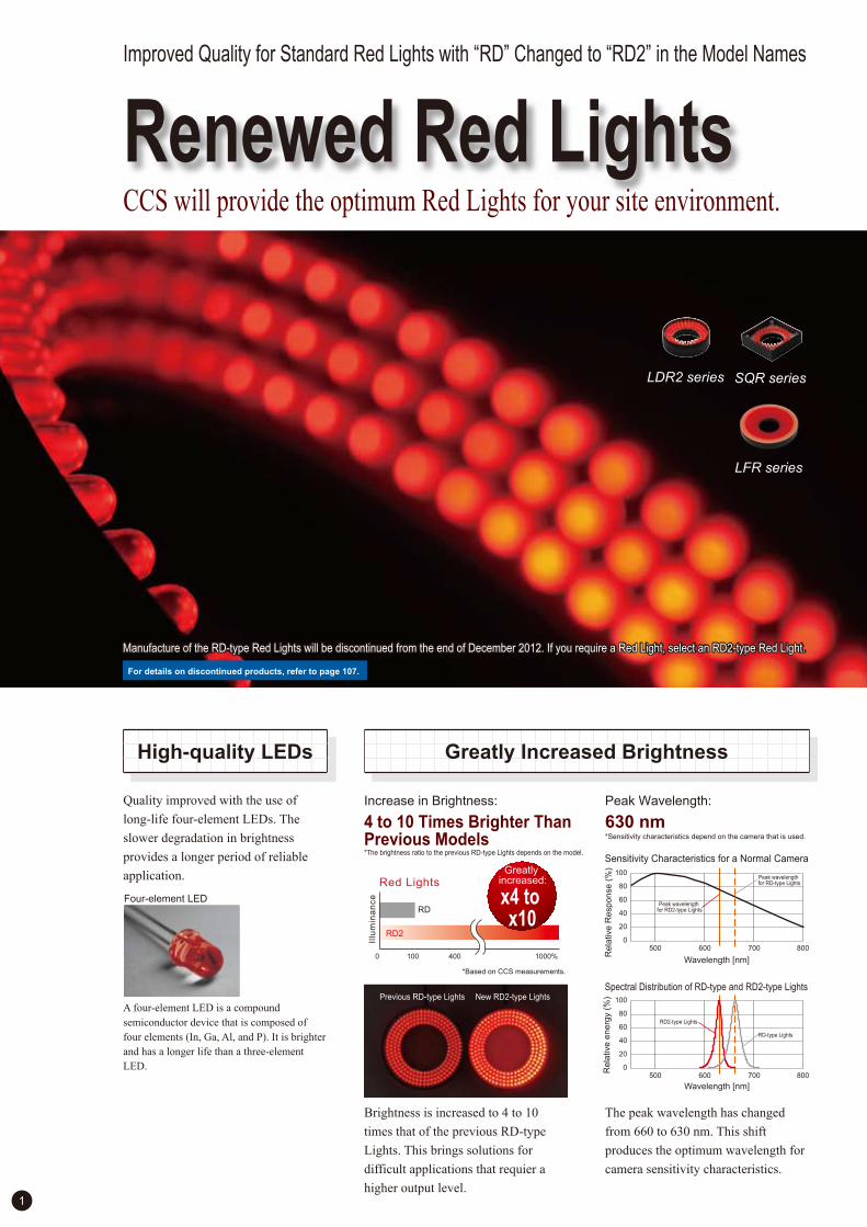
Renewed Red Lights Improved Quality for Standard Red Lights with “RD” Changed to “RD2” in the Model Names
CCS will provide the optimum Red Lights for your site environment.
Quality improved with the use of
long-life four-element LEDs. The
slower degradation in brightness
provides a longer period of reliable
application.
A four-element LED is a compound
semiconductor device that is composed of
four elements (In, Ga, Al, and P). It is brighter
and has a longer life than a three-element
LED.
Greatly Increased Brightness High-quality LEDs
1
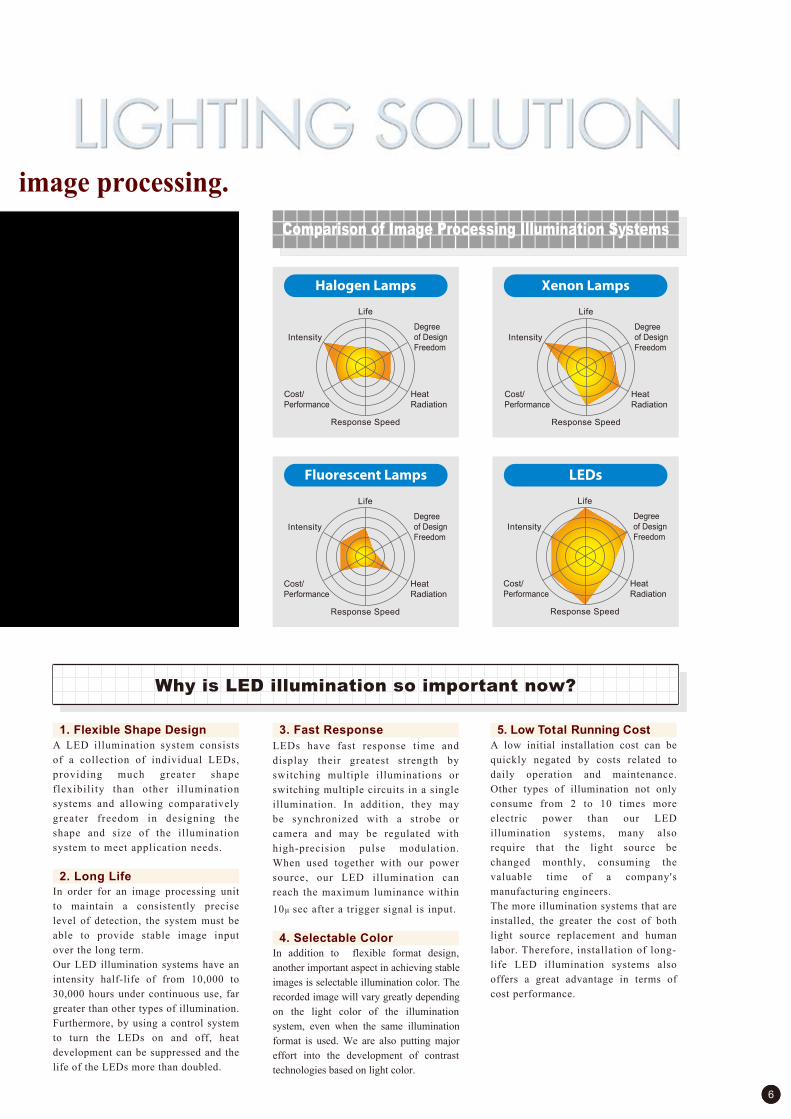
Increase in Brightness:
4 to 10 Times Brighter Than Previous Models
LFR series
SQR seriesLDR2 series
Four-element LED
Sensitivity Characteristics for a Normal Camera
Spectral Distribution of RD-type and RD2-type Lights
*The brightness ratio to the previous RD-type Lights depends on the model.
RD
RD2
1000% 0 100 400
Illu
min
an
ce
Red Lights
x4 to x10
Greatly increased:
*Based on CCS measurements.
Previous RD-type Lights New RD2-type Lights
Peak Wavelength:
630 nm
The peak wavelength has changed
from 660 to 630 nm. This shift
produces the optimum wavelength for
camera sensitivity characteristics.
*Sensitivity characteristics depend on the camera that is used.
Rela
tive R
esponse
(%
)
Wavelength [nm]
100
80
60
40
20
0 600 500 700 800
Wavelength [nm]
100
80
60
40
20
0600500 700 800
Rela
tive e
nerg
y (
%)
RD2-type Lights
Peak wavelength for RD2-type Lights
RD-type Lights
Peak wavelength for RD-type Lights
Brightness is increased to 4 to 10
times that of the previous RD-type
Lights. This brings solutions for
difficult applications that requier a
higher output level.
For details on discontinued products, refer to page 107.
Manufacture of the RD-type Red Lights will be discontinued from the end of December 2012. If you require a Red Light, select an RD2-type Red Light. Manufacture of the RD-type Red Lights will be discontinued from the end of December 2012. If you require a Red Light, select an RD2-type Red Light.

2
No Changes Required to Installation Dimensions Input Voltage Unified to 24 V
Control Units for RD2-type LED Lights
LDM2 series
LKR series
LFL series
LDR2-LA series LDR-LA1 series
FPR series
Size Example
Ø60
Ø120
Previous RD-type Lights
LDR2-120RD2-WD
Ø60
Ø120
New RD2-type Lights
The external dimensions and mounting hole positions are the
same as those of the previous RD-type Lights. This allows
you to use the previous installation dimensions.
Previous RD-type Lights
12-V Lights
Red, Blue, and Green Lights
24-V Lights
Lights that previously had 12-V input voltages were changed
to 24 V. This allows you to use the same Control Units for
Lights of any color.
All Lights unified to 24 V.
RD2-type Lights
Green Lights
Blue Lights
White Lights
3 Channels/28 W 4 Channels/46 W
Parallel Communications EIA-485 Communications
8 Channels/95 W
PD3-5024-4 seriesPD3-5024-4 seriesPD3-3024-3 seriesPD3-3024-3 series
PD3-10024-8 seriesPD3-10024-8 series
Perform external control through parallel, EIA-485, or Ethernet communications.
Ethernet
A Complete Lineup with Nine Different Models
PD3 series
Digital Control Units
*These Control Units do not include an overdrive.
For details, refer to page 79.
Previous Models
Renewed.
LV-27 seriesMSU series
PD3-series
External Controls
External Light Intensity Control
ON/OFF Control
Strobe Lighting
LDR2-120RD-WD

3
100-W Halogen Lamp
PFB2
PFB2
0
126,000 lx
220,000 lx
200,000 250,000(lx)150,000100,00050,000
0 20,000 25,000(Hours)15,00010,0005,000
The PFB2 Series for replacement of Halogen Light Sources
Long Lifetime at High Output
High Output
Long Lifetime
Refer to page 69 for details.
Features
• Achieves illumination of approximately 220,000 lx.
The LED Light Source Unit features a long lifetime while maintaining a high output by using power LEDs and a unique irradiation structure.
• Three types of external light intensity control are available: serial, parallel, and analog.
• All models available with AC or DC input power supply.
• Compact, width of 70 mm, a depth of 150 mm, and a height
of 100 mm.
• Features an LED light source with a long lifetime of 25,000 hours.
• Low power consumption at 15 W.
• Unique heat dissipating construction.
• Compatible with your current Light Guide.
*1 Refer to page 69 for details on the PFB2 Series LED Light Source Units.
*Actual value observed 50 mm from the end of the fiber.
*Actual values observed at 50 mm from the end of the fiber when a straight light guide with light
intensity control of 100% and joint diameter of 8 mm is attached.
*Calculated values until the light output decreases to 70% at a light intensity of 100% and an ambient temperature of 25°C.*The lifetime of halogen lamps is the nominal value provided by the manufacturer.
Illumination of 220,000 lx.
LEDs will not burn out like halogen lamps, and thus provide a much longer lifetime.
• Comparison of Illumination at 50 mm from the End of the Fiber
• Lifetime comparisons between the PFB2 and a 100-W Halogen Lamp
*Some brands are not supported.
*The light intensity and lifetime are reference values only.
*1
LED Lighting from CCS
Contributing to Society Through the Science of Light
Environmentally FriendlyEnvironmentally Friendly
PFB2 Series LED Light Source Units
Ecological performance with lower power consumptionand longer lifetime.
* The Light Guide is
not a CCS product.
100-W Halogen Lamp
25,000 hours
1,000 hours (nominal)
Lasts approx.25 times longer

4
The PFB2 Series Helps Reduce the Load on the Environment
Energy Efficient with Low Heat Generation
Power Consumption As Low As 15 W
A low energy consumption of 15 W reduces operating costs. Temperature increases in the surrounding environment will also besuppressed with a unique heat dissipating construction.
Contribute to the Prevention of Global Warming by Reducing Approx. 413 kg of CO2
*Observed using a thermograph one hour after continuous lighting is turned ON with light intensity control of 100% (reference values).*The Halogen Light Source is not a CCS product.
*Calculated by multiplying the output coefficient (0.555 kg CO2 per 1 kWh) by the power consumption.
Annual CO2 output by halogen lamps
Approx. 486 kg CO2 Approx. 73 kg CO2 Approx. 413 kg CO2
Annual CO2 output by PFB2 Annual CO2 reduction
Operating costs, such as for electricity, are reduced with energy efficiency.• Comparison of Power Consumption between the PFB2 and
a 100-W Halogen Lamp
• Comparison of CO2 Output between the PFB2 and a 100-W Halogen Lamp
Daily power consumption
15 W x 24 h = 360 Wh
131,400 Wh x 0.555 kg CO2
= 72.93 kg CO2
Annual power consumption
360 Wh x 365 (days) = 131,400 Wh
Daily power consumption
100 W x 24 h = 2,400 Wh
876 kWh x 0.555 kg CO2
= 486.18 kg CO2
Annual power consumption
2400 Wh x 365 (days) = 876,000 Wh
Power
consumption
Annual CO2
output
Case TemperatureTemperature increases in the surrounding environment are suppressed with a unique heat dissipating construction.• Comparison of Case Temperature between the PFB2 and a
100-W Halogen Lamp
100-W Halogen Light Source
100-W Halogen Light SourcePFB2
Consumes1/6 the Power
The PFB2 Series LED Light Source Units consume only 15 W, reducing power consumption greatly compared with 100-W halogen lamps. Low power consumption leads to the reduction of CO2 output, contributing to the prevention of global warming. By replacing halogen lamps with PFB2 Series LED Light Source Units, you can help reduce the load on the environment. To be environmentally friendly, that is the CCS approach.
Japan has implemented many measures to cut emissions of CO2 and other greenhouse
gases by 6% from 1990 levels between 2008 and 2012, as stipulated under the Kyoto
Protocol that was issued February 16, 2005. Then at the UN Climate Change Summit in New
York in September 2009, Japan announced plans to cut greenhouse gas emissions by 25%
over 1990 levels by 2020. The name chosen, Challenge 25, acquired fresh life the following
January with the Challenge 25 Campaign, a national movement to promote measures to
prevent global warming. Carbon dioxide alone accounts for at least 90% of the total
emissions for the targeted six greenhouse gases, so reducing CO2 emissions is imperative.
The second graph below shows how manufacturing factories and other parts of the industry
category constitute over 30% of emissions, making it the largest group. For this reason,
cutting down on emissions demands improvements in energy utilization efficiency in
production facilities and processes, along with technology developments and other
measures. From here on, tackling environmental issues will be an increasingly important
task as businesses address the demands for emission reductions.
About Global Warming
100W
15WPFB2
0 100(W)10 20 30 40 50 60 70 80 90
100-W Halogen Light Source
PFB2
For more information about Global
Warming please use the
following resources.
Ministry of the Environment
(Global Environment /
Global Environmental Cooperation)
http://www.env.go.jp/
Japan Center for Climate
Change Actions(JCCCA)
http://www.jccca.org/
Source: Greenhouse Gas Inventory Office "The Greenhouse Gases Emissions Data of the Years 1990 to 2009" (Released on April 26, 2011)
Percentage of greenhouse gas emissions regulated under the Kyoto
Protocol in Japan
Nitrous oxide(N2O) 1.8%
Hydro fluorocarbons(HFCs) 1.4% Per fluorocarbons
(PFCs) 0.3%
Sulfur hexafluoride(SF6) 0.2%
1,209 million tons[Equivalent in carbon dioxide(CO2)] of 2009
Carbon dioxide(CO2)94.7%
Methane(CH4) 1.7%
Percentage of carbon dioxideemissions for each industrial
sector in Japan Indirect emissions for each industrial sector
1,145 million tons[Equivalent incarbon dioxide(CO2)] of 2009
Commercial(Home use)
sector 14.1%
Commercial(service)
sector 18.8%
Transportationsector 20.6%
Industrialprocess 3.5%
Waste 2.5%
Energyconversionsector 7.0%
Industrialsector33.9%

5
The Image Processing Industry Today and Image Processing Needs
KnowWe know that lighting is the key to successful image processing.
Recently, image processing devices with
high performance and low price come to
the market one after another. The feilds of
application of them, such as the detection
of appearances, the decision of position
and the assembling of products become
wider and wider. It is mainly due to the
high-speed processing, the improvement
of sensitivity, the improvement of the
processing performance of CPU of a
personal computer and the development
of the device technology. This means that
it is difficult to discriminate one maker
treating image processing devices from
others.As for end-users, it is possible to
budget for illuminations because the price
of image processing units is low.
The recognition that the success of
introducing an image processing
system depends on the lightings
becomes widespread.
To realize a stable system, it is a
necessary condition to get images with
sharp contrasts constantly in spite of the
various changes of external conditions,
such as external noise lights, the lean of a
work, the variation of materials and the
type of a system. Keeping this in mind, it
is important to choose an illumination
system that can overcome the factors
normally present in a factory setting, yet
still provide superior, high contrast
images. Unfortunately, there is no one
universal illumination system that would
be applicable to all types of work such as
the manufacturing of semiconductors,
electronic parts, medical products, food
products, printed materials and
automobile parts. In order to achieve
maximum stability under a limited set of
conditions, it has become even more vital
to select the best type of illumination for
the target application from the many
systems that are available. Many times
this requires custom lighting
development. As the adage goes "better to
light than write!" This evolution has
naturally spurred massive development in
the area of illumination. In spite of this,
20% to 30% or more of all work requiring
illumination still cannot be solved with
standard solutions, requiring custom
illumination development and further
driving the advancements in illumination.
Indeed, it is clear that the future
advancement of image processing
technology must go hand-in-hand with
the requisite advances in illumination.
Development in Image Processing and the Mission of Illumination
6
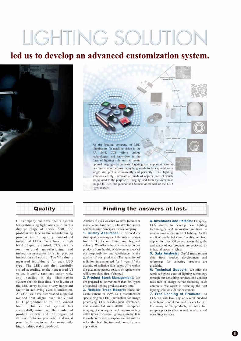
Comparison of Image Processing Illumination Systems
We know that lighting is the key to successful image processing.
Life
Intensity
Degree
of Design
Freedom
Cost/
Performance
Heat
Radiation
Response Speed
Halogen Lamps Xenon Lamps
LEDsFluorescent Lamps
Life
Intensity
Degree
of Design
Freedom
Cost/
Performance
Heat
Radiation
Response Speed
Life
Intensity
Degree
of Design
Freedom
Cost/
Performance
Heat
Radiation
Response Speed
Life
Intensity
Degree
of Design
Freedom
Cost/
Performance
Heat
Radiation
Response Speed
A LED illumination system consists
of a collection of individual LEDs,
providing much greater shape
flexibili ty than other i l lumination
systems and allowing comparatively
greater freedom in designing the
shape and size of the illumination
system to meet application needs.
In order for an image processing unit
to maintain a consistently precise
level of detection, the system must be
able to provide stable image input
over the long term.
Our LED illumination systems have an
intensity half-life of from 10,000 to
30,000 hours under continuous use, far
greater than other types of illumination.
Furthermore, by using a control system
to turn the LEDs on and off, heat
development can be suppressed and the
life of the LEDs more than doubled.
LEDs have fast response time and
display their greatest strength by
switching multiple illuminations or
switching multiple circuits in a single
illumination. In addition, they may
be synchronized with a strobe or
camera and may be regulated with
high-precision pulse modulation.
When used together with our power
source, our LED illumination can
reach the maximum luminance within
10! sec after a trigger signal is input.
In addition to flexible format design,
another important aspect in achieving stable
images is selectable illumination color. The
recorded image will vary greatly depending
on the light color of the illumination
system, even when the same illumination
format is used. We are also putting major
effort into the development of contrast
technologies based on light color.
A low initial installation cost can be
quickly negated by costs related to
daily operation and maintenance.
Other types of illumination not only
consume from 2 to 10 times more
electric power than our LED
illumination systems, many also
require that the light source be
changed monthly, consuming the
valuable time of a company's
manufacturing engineers.
The more illumination systems that are
installed, the greater the cost of both
light source replacement and human
labor. Therefore, installation of long-
life LED illumination systems also
offers a great advantage in terms of
cost performance.
Why is LED illumination so important now?
1. Flexible Shape Design
2. Long Life
3. Fast Response
4. Selectable Color
5. Low Total Running Cost

7
ThinkThe necessity of customization.
The desire to meet our customers' needs of 4,000 has led us to develop an advanced customization system.
Image processing applications can be
classified into four general groups: visual
inspection, character recognition,
measuring dimensions, and positioning. In
designing a lighting system, it is necessary
to optimize the signal-to-noise ratio of the
acquired image by adjusting the irradiation
wavelength and the parallelism of the light
for each of these applications.
As our company strives to meet the
diverse needs of all our customers, we
have come to realize that the advantages
offered by LED illumination - compact
size, low power consumption, long life
and design flexibility - make LEDs
ideally suited to a diverse range of work
applications.
When imaging identical work pieces
using identical illumination, the
installation position and illumination
angle can greatly affect the resulting
image. Therefore, four aspects of the
work process must always be
considered when developing an
illumination system.
As the solid angle of the utilized light
changes significantly depending on the
FOV range, work distance, and
numerical aperture, the image will
change in a similar way as it changes
when lighting is changed. In addition, the
lighting system is dependant on whether
the imaging method is area or line.
Attention must be paid to the
wavelength and parallelism of the
specified light, carefully matching it
to the physical characteristics, surface
status, shape, material, and color of
the object and features to be imaged.
The shutter speed and scan rate will change
depending on whether the workpiece is
stopped or moving, so techniques to
optimize of the quantity of light such as
strobing and overdriving may be necessary,
as well as designing resistance against
ambient conditions such as moisture,
vibration, and ambient light.
Development The four points to specifying a lighting solution.
Workpiece to be
illuminated2
Imaging and optics
system3
Operation mechanism
and ambient environment4
Application1
8
The desire to meet our customers' needs of 4,000 has led us to develop an advanced customization system.
Semiconductors and
Electronic Parts
Foods and
Pharmaceuticals
LCD Plates
Glasses, Bottles and Lenses
Cans and Plastics
Automobiles and Machine Parts
Answers to questions that we have faced over
many years have led us to develop seven
comprehensive principles for our company.
1. Quality Assurance: CCS conducts
strict quality management through all stages
from LED selection, fitting, assembly, and
delivery. We offer a 2-years warranty on our
products from the date of delivery as proof of
our responsibility and confidence in the
quality of our products. (The quantity of
radiation is guaranteed for 1 year: If the
quantity of radiation falls below 50% within
the guarantee period, repairs or replacement
will be provided free of charge.)
2. Product Stock Management: We
are prepared to deliver more than 300 types
of standard lighting products at any time.
3. Reliable Track Record: Since our
establishment in 1993 as a manufacturer
specializing in LED illumination for image
processing, CCS has designed, developed,
and constructed over 40,000 workpiece
imaging technologies and approximately
4,000 types of custom lighting systems. It is
through our extensive experience that we can
offer the best lighting solutions for any
application.
4. Inventions and Patents: Everyday,
CCS strives to develop new lighting
technologies and innovative solutions to
remain number one in LED lighting. As the
result of our high technical ability, we have
applied for over 500 patents across the globe
and many of our products are protected by
industrial property rights.
5. Data Analysis: Useful measurement
data from product development and
references for selecting products are
available.
6. Technical Support: We offer the
world’s highest class of lighting technology
through our consulting services, and conduct
tests free of charge before finalizing sales
contracts. We assist in selecting the best
lighting solutions for our customers.
7. Free Loaning of Products: At
CCS we will loan any of several hundred
models and several thousand devices for free.
For many of the products, we offer free
samples prior to sales, as well as advice and
consulting services.
Our company has developed a system
for customizing light sources to meet a
diverse range of needs. Still, one
problem we face in the manufacturing
process is the quality control of
individual LEDs. To achieve a high
level of quality control, CCS uses its
own original manufacturing and
inspection processes for strict product
inspection and control. The Vf value is
measured individually for each LED
type. The LEDs are then carefully
sorted according to their measured Vf
value, intensity rank and color rank,
and installed in the illumination
system for the first time. The layout of
the LED array is also a very important
factor in achieving even illumination.
At CCS, we have established a special
method that aligns each individual
LED perpendicular to the circuit
board. Our control system has
successfully minimized the number of
product defects and the degree of
variance between products, making it
possible for us to supply consistently
high-quality, stable products.
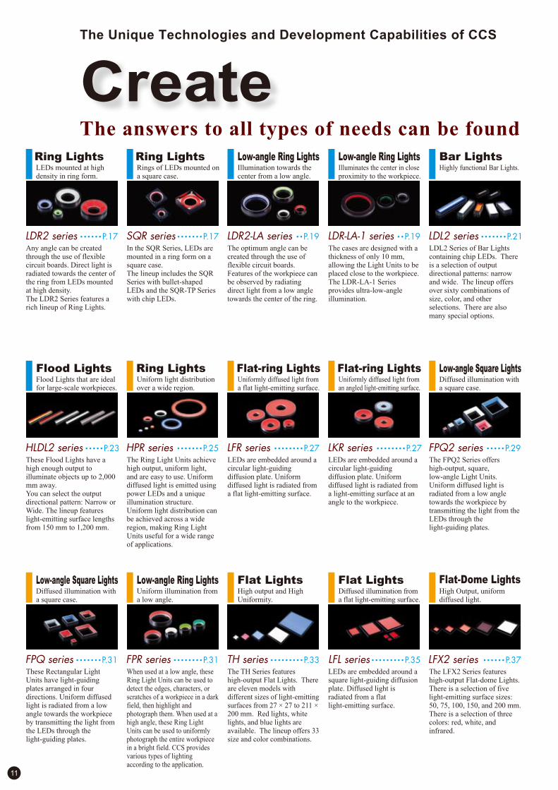
As the leading company of LED
illuminators for machine vision in the
FA field, CCS offers unique
technologies and know-how in the
form of lighting solutions, to create
optimal imaging environments. Lighting is an important factor in
machine vision, because everything needs to be captured on a
single still picture consistently and perfectly. Our lighting
solutions vividly illuminate all kinds of objects, each of which
are tailored to the purpose of imaging, and form the know-how
unique to CCS, the pioneer and foundation-builder of the LED
lights market.
Quality Finding the answers at last.
Lighting control technology
Lighting method Parallelism
Wave length Irradiation area
Lighting technology

9
Direct Lighting Ring LightsLEDs mounted at high density in ring form.
Flexible circuit boards.
Unique heat dissipating construction.
Indirect Lighting Flat-ring LightsUniform light diffusion is achieved through
unique illumination technology.
A special dot pattern controls light diffusion and
transmission.
The characteristics of coaxial lighting and dome
lighting are recreated.
Parts for the semiconductor industry, parts
which are growing continuously smaller,
require the use of image processing at
various stages of the automatic
manufacturing line. Numerous illumination
systems are used in these processes.
Today, LCD plates are used in virtually
all types of home electronics, from
computers to cellular telephones. CCS
LED illumination systems are being
used in the manufacturing and control
of these types of transparent plates.
The full advantages of LED illumination
systems can be realized in the high-
speed, reliable inspection processes
required for the mass production of
cans, plastic drink bottles, etc.
Semiconductors and Electronic Parts
LCD Plates Cans and Plastics
RealizeCCS - a company that is meeting needs.
Like the changing times, there is no limit to the challenges CCS undertakes.

10
Convergent-beam LightingRadiation of converged line light.
White power LEDs.
Light is converged using cylindrical lenses.
LED Light Source UnitLED Light Sources that can replace halogen light
sources.
White power LEDs.
Unique light converging technology and heat
dissipating construction.
LED illumination systems are being
used for damage inspection and
external inspection as part of the
manufacturing processes of O-rings
and bearings used to manufacture
automobile and machine parts.
Chipping and scratching can occur during
the manufacturing of clear objects such
as glass sheets, bottles and lenses. Many
objects that could not be accurately inspected
visually can now be inspected using
LED illumination and image processing.
The stable, color-selectable output of
LED illumination systems makes them
ideal for use in the inspection
processes required by the strict quality
controls used in food and
pharmaceutical product manufacturing.
Automobile and Machine Parts
Glass Sheets, Bottles and Lenses
Food Products and Pharmaceuticals
Like the changing times, there is no limit to the challenges CCS undertakes.
Ring LightsLEDs mounted at high density in ring form.
Ring LightsRings of LEDs mounted on a square case.
Low-angle Ring Lights Low-angle Ring LightsIllumination towards the center from a low angle.
Illuminates the center in close proximity to the workpiece.
LDR2 series • • • • • •P.17 SQR series • • • • • • •P.17 LDR2!LA series • •P.19 LDR!LA!1 series • •P.19
Any angle can be created through the use of flexible circuit boards. Direct light is radiated towards the center of the ring from LEDs mounted at high density.The LDR2 Series features a rich lineup of Ring Lights.
In the SQR Series, LEDs are mounted in a ring form on a square case.The lineup includes the SQR Series with bullet-shaped LEDs and the SQR-TP Series with chip LEDs.
The optimum angle can be created through the use of flexible circuit boards. Features of the workpiece can be observed by radiating direct light from a low angle towards the center of the ring.
The cases are designed with a thickness of only 10 mm, allowing the Light Units to be placed close to the workpiece.The LDR-LA-1 Series provides ultra-low-angle illumination.
Ring LightsUniform light distribution over a wide region.
Flat-ring LightsUniformly diffused light from a flat light-emitting surface.
Flat-ring LightsUniformly diffused light from an angled light-emitting surface.
HPR series • • • • • • •P.25 LFR series • • • • • • • •P.27
Bar LightsHighly functional Bar Lights.
LDL2 series • • • • • • •P.21
LDL2 Series of Bar Lights containing chip LEDs. There is a selection of output directional patterns: narrow and wide. The lineup offers over sixty combinations of size, color, and other selections. There are also many special options.
Flood LightsFlood Lights that are ideal for large-scale workpieces.
HLDL2 series • • • • •P.23
These Flood Lights have a high enough output to illuminate objects up to 2,000 mm away.You can select the output directional pattern: Narrow or Wide. The lineup features light-emitting surface lengths from 150 mm to 1,200 mm.
The Ring Light Units achieve high output, uniform light, and are easy to use. Uniform diffused light is emitted using power LEDs and a unique illumination structure. Uniform light distribution can be achieved across a wide region, making Ring Light Units useful for a wide range of applications.
LEDs are embedded around a circular light-guiding diffusion plate. Uniform diffused light is radiated from a flat light-emitting surface.
LEDs are embedded around a circular light-guiding diffusion plate. Uniform diffused light is radiated from a light-emitting surface at an angle to the workpiece.
LKR series • • • • • • • •P.27
11
Diffused illumination from a flat light-emitting surface.
Flat Lights
LEDs are embedded around a square light-guiding diffusion plate. Diffused light is radiated from a flat light-emitting surface.
LFL series • • • • • • • • •P.35
High Output, uniform diffused light.
The LFX2 Series features high-output Flat-dome Lights. There is a selection of five light-emitting surface sizes: 50, 75, 100, 150, and 200 mm. There is a selection of three colors: red, white, and infrared.
LFX2 series • • • • • •P.37
Flat-Dome LightsLow-angle Square LightsDiffused illumination with a square case.
• • • • • • •P.31FPQ seriesThese Rectangular Light Units have light-guiding plates arranged in four directions. Uniform diffused light is radiated from a low angle towards the workpiece by transmitting the light from the LEDs through the light-guiding plates.
Low-angle Square LightsDiffused illumination with a square case.
• • • • •P.29FPQ2 seriesThe FPQ2 Series offers high-output, square, low-angle Light Units. Uniform diffused light is radiated from a low angle towards the workpiece by transmitting the light from the LEDs through the light-guiding plates.
Flat LightsHigh output and High Uniformity.
TH series • • • • • • • • •P.33
The TH Series features high-output Flat Lights. There are eleven models with different sizes of light-emitting surfaces from 27 ! 27 to 211 ! 200 mm. Red lights, white lights, and blue lights are available. The lineup offers 33 size and color combinations.
Uniform illumination from a low angle.
When used at a low angle, these Ring Light Units can be used to detect the edges, characters, or scratches of a workpiece in a dark field, then highlight and photograph them. When used at a high angle, these Ring Light Units can be used to uniformly photograph the entire workpiece in a bright field. CCS provides various types of lighting according to the application.
FPR series • • • • • • • •P.31
Low-angle Ring Lights
The Unique Technologies and Development Capabilities of CCS
CreateThe answers to all types of needs can be found in our creativeness.

12
The LFV2 Series features Coaxial Drop Lights with a built-in heat-dispersing structure. Even illumination is provided for mirrors and other highly reflective workpieces. These lights are ideal for photographing scratches, dents, and text.
LFV2 series • • • • • •P.45
Coaxial LightsUniform illumination of mirrored surfaces.
Dome LightsPhotographing curved glossy workpieces.
The light from LEDs is transmitted through a light-guiding plate to illuminate the entire workpiece with uniform diffused light from a wide light-emitting surface.
LDM2 series • • • • •P.43
Dome LightsUniform diffused radiation.
These Dome Light Units achieve high output, uniform light, and are easy to use. Uniform diffused light is radiated using power LEDs and a unique illumination structure. Uniform light distribution can be achieved across a wide region, making Dome Light Units useful for a wide range of applications.
HPD series • • • • • • •P.41
Coaxial LightsUniform illumination of mirrored surfaces.
The LFV Series features Coaxial Drop Lights. Even illumination is provided for mirrors and other highly reflective workpieces. These lights are ideal for photographing scratches, dents, and text.
LFV series • • • • • • • •P.45
These are line-type Coaxial Light Units. They are ideal for photography with a line sensor camera.
Coaxial LightsUniform illumination of mirrored surfaces.
LNV series • • • • • • •P.45
Flat-Dome LightsUnique lighting technology achieves uniform, shadowless diffused illumination.
The diffusion and transmission of light is controlled through the dot pattern on the surface of the light-guiding diffusion plate, enabling the workpiece to be illuminated with uniform diffused light. Mounting space is reduced due to the slim, compact, and lightweight construction. Application is possible in locations where coaxial or dome lighting was difficult to install previously.
LFX series • • • • • • • •P.39
These Line Light Units achieve a high output by using power LEDs and a unique illumination structure. A standard type (T) and a high-intensity type (R) are available. The light-emitting surface can have a minimum length of 100 mm and a maximum length of 2,700 mm and can be created in increments of 100 mm. Red or white LEDs can be chosen.
Line LightsLine Light Units with high output.
HLND series • • • • •P.51
Unique optics achieve the twin goals of high uniformity and high luminance. They enable highly precise inspections, and can also be used for fast shutter speeds. We can manufacture light-emitting surface lengths from 100 mm to 1,800 mm in 100 mm increments.
Line LightsHigh Uniformity and High Intensity.
LT series • • • • • • • • • •P.49
Less diffusion means less loss of light quantity for long distance irradiation.Select from sizes of 100 mm to 1,000 mm to meet your specific needs for a wide variety of applications.
Line LightsHigh-output Line Light Unit with Reduced Diffusion
LNSP series • • • • • •P.47
These Line Light Units feature high-density chip LEDs. The A-type Light Units have a wide emitting surface, and the H-type Light Units have a narrow light-emitting surface.
Line LightsIdeal for photographing with a line sensor camera.
LND series • • • • • • •P.53
These Line Light Units radiate light that is converged into a straight line by cylindrical lenses. Two types are available, one with a light-emitting surface length of 60 mm and another with a length of 200 mm. There is also the LN-HK Series, which achieve high output using white power LEDs and a unique heat dissipating construction.
Line LightsLine Light Units that radiate converged light.
LN series • • • • • • • • •P.55
The answers to all types of needs can be found in our creativeness.
Parallel light beams are created by a special lens. These Collimated Light Units are ideal for detecting minute scratches, dents, and marks.
Coaxial LightsDetecting scratches, dents, and marks on mirrored surfaces.
MSU series • • • • • •P.57
These Collimated Backlight Units are used to radiate parallel light from behind the workpiece, enabling external inspection with high accuracy by suppressing the scattering of light.
Coaxial LightsDetecting scratches, dents, and marks on mirrored surfaces.
MFU series • • • • • • •P.57

Light Sources for Micro Fiber-headsAllow users to choose the illumination color and intensity.
The HLV2-22-NR-3W Series features high-output Light Sources for Microfiber Heads. There is a selection of four colors: red, white, blue, and green.
• •P.66HLV2!22!NR!3W series
Light Sources for Micro Fiber-headsAllow users to tailor the illumination color to the target object.
The HLV2-3M-RGB-3W Light Source for Microfiber Heads combine a light source and a Blending Unit. They incorporate a high-output HLV2-22-NR-3W-series Light Source. Freely mix red, blue, and green light to produce the desired illumination color.
HLV2!3M!RGB!3W • •P.67
Macro LensUnique macro lens.
The SE-16 Series of original Macro Lenses provide both high performance and low prices. The lineup offers magnifications of 0.5, 1.0, and 2.0.
SE!16 series • • • • •P.71
Macro LensUnique macro lens.
The SE-18 Series of original Macro Lenses provide both high performance and low prices. The lineup offers magnifications of 2, 4, and 6.
SE!18 series • • • • •P.71
Spot LightsSuper-Uniform Spotlights.
Super-Uniform Spotlight for wide variety of applications.
LSP!41 series • • • •P.73
Spot LightsLightweight and compact Spotlights.
The LV Series of light, compact, power-saving, long-life Spot Lights. These attach to, for example, Macro Lenses with coaxial drop lighting.
LV series • • • • • • • • •P.74
Digital Control UnitsFully Equipped with External Control Functions
The PD3 Series consists of high-performance Digital Control Units with a full suite of external control functions. It supports parallel communications, EIA-485 communications, and Ethernet. The light intensity can be set to any of 256 different levels. It supports constant lighting, ON/OFF lighting, and strobe lighting modes.
PD3 series • • • • • • •P.79
Digital Control UnitsIntensity control to 256 levels.
The PD2 Series of Digital Control Units were designed specially for CCS LED Lights. They offer a broader range of intensity control in comparison to analog Control Units: 256 levels. A full lineup supports a broad range of applications.
PD2 series • • • • • • •P.87
The PSB3-30024 Analog Control Units provide a high capacity of 300 W. The light intensity can be set to any of 256 different levels. The PSB3-30024 is equipped for parallel communications, serial communications, and analog input for external control all in a single Unit. You can easily change the intensity range for the optimal output for any Light Unit.
PSB3!30024 • • • • • •P.89
Analog Control UnitsHigh-capacity Analog Control Unit
These Compact Spotlights have long life time with their light weight, compactness, and low power consumption. The HLV2 Series of high-output Spot Lights can be used to replace 100-watt halogen light sources.
Spot LightsHigh-output Spot Light.
HLV2 series • • • • •P.63
An output that is high enough to enable replacing halogen light sources is achieved using white power LEDs and a unique light-converging technology. These environmentally friendly, next-generation LED Light Sources feature low power consumption, a long service life, and a significant reduction in maintenance work compared with 100-W halogen light sources.
LED Light Source UnitUsed to replace halogen light sources.
PFB2 series • • • • • •P.69
Micro Fiber-headsLED fiber system.
This lighting system combines the advantages of LEDs and fibers.
HFS!14!500 • • • • •P.65
This lighting system combines the advantages of LEDs and fibers.
LED fiber system.
HFR series • • • • • • •P.65
Micro Fiber-heads
13
The Unique Technologies and Development Capabilities of CCS
CreateThe answers to all types of needs can be found in our creativeness.
Ultraviolet lighting Series using UV light LEDs with CCS's unique spark prevention structure. Since ultraviolet light with its shorter wavelength has a higher scattering rate and is likely to cause fluorescence it can be effectively used for various inspections that cannot be performed well by means of visible light.
Ultraviolet LightsFor various inspections by using differences in scattering rates.
UV series • • • • • • • •P.59
Infrared lighting Series using infrared light LEDs with peak wavelengths of 850nm and 940nm. Since infrared light with its longer wavelengths has a lower scattering rate and higher transmittance, it can be optimally used for various inspections by means of its property of transmission through objects.
Infrared LightsHigher transmittance than visible light.
IR series • • • • • • • • •P.61

Strobe Control UnitsStrobing provides control over illumination intervals.
The PTU2 Series of Control Units enable strobe operation of LED Lights. Features include switching the Digital control unit ON and OFF and boosting strobe output beyond those available with the STU-3000 Series. And an overdrive feature is also provided.
PTU2 series • • • • • •P.92
Analog Control UnitsPopularly priced LED light Control Units.
The PSB Series of Analog Control Units provide stepless intensity control for a variable voltage. The constant output makes them ideal for high shutter speeds of 1/4,000 and faster.
PSB series • • • • • • •P.91
Storobe UnitStrobing with a Digital Power Supply.
Connected to one of our PD2-series Digital Control Units, an STU-3000 Strobe Unit converts a constantly lit LED Light into a strobe.
STU!3000 • • • • • • • •P.92
Analog Control UnitsCompact and Efficient.
These Analog control unit Units enable controlling the light intensity for both 12V and 24V LED Light Units from a single Unit.
PB!2430 • • • • • • • • •P.93
Strobe Control UnitsHigh Performance and Low Price.
Cost-effective, easy-to-use strobe control unit with overdriving power output. It operates with 24V DC voltage input.
PS!3012!D24 • • • •P.93
Building BlockControl UnitsA wide variety of system configurations.
The BB Series features building-block Control Units that link together. Link the necessary units together to enable flexible illumination control. The 10-model lineup offers such selections as constant output and strobing. They support DIN rail mounting. Input specification: 24 V DC.
BB series • • • • • • • • •P.95
The compact, lightweight CC-ST-1024 Controller was designed specially for LED Lights. Installing the Controller inside panels or equipment (e.g., next to sensor amplifiers) makes the system configuration more compact. They provide constant output, strobing, and ON/OFF control. They support DIN rail mounting. Input specification: 24 V DC.
CC!ST!1024 • • • • •P.94
Compact ControllerCompact, lightweight Controllers.
This Compact Controller is for HLV2-series Spotlights. They provide constant output, strobing, and ON/OFF control. They support DIN rail mounting. Input specification: 24 V DC.
CC!PJ!0707 • • • • •P.97
Dedicated Compact ControllerHLV2 Series dedicated compact controller.
These Control Units are for the HLV2 Series of Spot Lights. They provide stepless intensity control for a variable current. There is a selection of inputs available: 100 to 240 V AC and 24 V DC.
PJ series • • • • • • • • • •P.98
Dedicated Control UnitsHLV2 Series dedicated control unit.
OptionVariety of options available.
Sharp Cut Filters, Diffusion Plates, Polarizing Plates, and Mounting Brackets are among the many optional parts that are available.
Optional Parts • • •P.99
OptionWide variety of cables.
Extension Cables and Branch Cables are among the many cables that are available.
Optional Cable • •P.102
14
The answers to all types of needs can be found in our creativeness.
Index
15
Contents
• • • • • • • • • • • • • • • • • • • • • • • • • • • • • • • • • • •P.1 to 14LIGHTING SOLUTION
DirectLighting
Ring Lights LDR2/SQR seriesHigh-density light output produces fresh, vivid images.
• • • • • • • • • • • • • • • • • • • • • • • • • •P.17
• • • • • • • • • • • • • • • • • • •P.31Low-angle Square Lights FPQ series
Low-angle Ring Lights FPR seriesEven, diffused side lighting.
• • • • • • • • • • • • • • • • • •P.29Low-angle Square Lights FPQ2 seriesEven, diffused side lighting.
• • • • • • • • • • • • • • • • • • • • • • • • •P.27Flat-ring Lights LFR/LKR seriesEven, diffused top lighting.
• • • • • • • • • • • • • • • • • • • • • • • • • • • • • • • • • • • •P.33Flat Lights TH seriesHigh output and High Uniformity.
• • • • • • • • • • • • • • • • • • • • • • • • • • • • • • • • • • • •P.35Flat Lights LFL seriesInspection of work by silhouette using uniform light.
• • • • • • • • • • • • • • • • • • • • • • • • • • •P.37Flat-Dome Lights LFX2 seriesHigh Output, uniform diffused light.
• • • • • • • • • • • • • • • • • • • • • • • • • • • •P.39Flat-Dome Lights LFX seriesUnique lighting technology achieves uniform omni directional
diffused light.
• • • • • • • • • • • • • • • • • • • • • • • • • • • • • • • •P.41Dome Lights HPD series"Brighter" "More uniform" "Easy to use" High-Power Dome Lights.
• • • • • • • • • • • • • • • • • • • • • • • • • • • • • •P.43Dome Lights LDM2 seriesFor inspection of workpiece with curved and glossy surface.
• • • • • •P.45Coaxial Lights LFV/LFV2/LFV2!CP/LFV2!5 series
Line Lights with Coaxial System LNV seriesUniform illumination for highly reflective surfaces.
Line Lights LND seriesIdeal for use in line sensors.
• • • • • • • • • • • • • • • • • • • • • • • • • • • • • • • • •P.53
• • • • • • • • • • • • • • • • • • • • • • • • • • • • • • •P.51Line Lights HLND series Next-generation light for line scan applications featuring
unprecedented intensity and uniformity.
• • • • • • • • • • • • • • • • • • • • • • • • • • • • • • • • • • • •P.49Line Lights LT seriesHigh Uniformity and High Intensity.
• • • • • • • • • • • • • • • • • • • • • • • • • • • • • • • •P.47Line Lights LNSP seriesHigh-output Line Light Unit with Reduced Diffusion.
Bar Lights LDL2 seriesHighly functional Bar Lights.
• • • • • • • • • • • • • • • • • • • • • • • • • • • • • • • • • •P.21
Flood Lights HLDL2 seriesFlood Lights that are ideal for large-scale workpieces.
• • • • • • • • • • • • • • • • • • • • • • • • • • • • • •P.23
Low-angle Ring Lights LDR2!LA/LDR!LA!1 seriesIdeal for work piece edge detection and for
detecting scratches on glossy surfaces.
• • • • • • •P.19
Indirect Lighting
• • • • • • • • • • • • • • • • • • • • • • • • • • • • • • • • •P.25Ring Lights HPR series"Brighter" "More uniform" "Easy to use" High-Power Ring Lights.
Special
Control Units for LED lights
Optional Parts
Optional Cables
Technology Overview
Discontinued products Information
CCS Worldwide Support
• • • • • • • • • • • • • • • • • • • •P.75 to P.98
• • • • • • • • • • • • • • • • • • • • • • • • • • • • • • • •P.99 to P.101
• • • • • • • • • • • • • • • • • • • • • • • • • • • • • • • • • • • • • •P.102
• • • • • • • • • • • • • • • • • • • • • • • •P.103 to P.106
• • • • • • • • • • • • • • • • • • • •P.107
• • • • • • • • • • • • • • • • • • • • • • • • • • • • •P.109
• • • • • • •P.63Spot Lights HLV2!14/HLV2!22/HLV2!22!3W seriesHigh-output Spot Light.
• • • • • • • • • • • • • • • • • • • • •P.69LED Light Source Unit PFB2 seriesUsed to replace halogen light sources.
• •P.66Light Sources for Micro Fiber-heads HLV2!22!NR!3W seriesLED fiber system and light sources.
• • • • • • • • • • • • • • • • • • • • • • • •P.65Micro Fiber-heads HFR/HFS series
• • •P.67Light Sources for Micro Fiber-heads HLV2!3M!RGB!3W Allow users to tailor the illumination color to the target object.
• • • • • • • • • • • • • • • • • • • • •P.71Macro Lenses SE!16/SE!18 seriesCCS macro lens, high performance at a low price.
Spot Lights LV seriesFor special applications.
• • • • • • • • • • • • • • • • • • • • • • • • • • • • • • • • • • • • •P.74
Spot Lights LSP!41 series • • • • • • • • • • • • • • • • • • • • • • • • • • • • • • •P.73
UltravioletLighting
Ultraviolet Lights UV series For various inspections by using differences in scattering rates.
• • • • • • • • • • • • • • • • • • • • • • • • • • • • •P.59
InfraredLighting
Infrared Lights IR seriesHigher transmittance than visible light.
• • • • • • • • • • • • • • • • • • • • • • • • • • • • • • • • •P.61
Convergent-beam Lighting
Line Lights LN series Line shaped, convergent-beam lighting.
• • • • • • • • • • • • • • • • • • • • • • • • • • • • • • • • • • •P.55
Collimated-Lighting
Coaxial Lights MSU/MFU seriesUsed to detect scratches, indentations and dirt on mirrored work
surfaces.
• • • • • • • • • • • • • • • • • • • • • • •P.57

16
Information
The following codes are used to indicate options in the product selection tables:
D
P
C
A
L
B
Diffuser (DF)
Polarizer (PL)
Protecter (CV)
Adapter (AD)
Light Control Film (LC)
Bracket (BK)
Used to eliminate glare etc. that can be a problem when imaging glossy objects.
Used in combination with a polarizing filter to eliminate surface reflection
This cover shields the light-emitting portion.
Used when attaching a diffuser or polarizer to an illuminators.
Plastic film with fine louvers. Suppresses diffusion of light and improves parallelism. Prevents leakage and diffraction of light that may occur when the distance of illumination and the workpiece is close.
This Bracket is for securing the Light.
Accessories listed in the Product lineup tables
About EU Directive ...
In accordance with EU machinery directive, EMC directive, and low voltage directive, machines and electronic devices not marked with the CE logo are subject to distribution restrictions within the EU.
All CCS LED illumination system products and illumination system control units conform to corresponding EN regulations.
These products will maintain the EU mandate compatibility of our customers' machinery and electronic devices.
LDR2, SQR, LDR2-LA, LDR-LA-1, LDL2, HLDL2, HPR, LFR, LKR, FPR, FPQ,
FPQ2, TH, LFL, LFX2, LFX, HPD, LDM2, LFV, LFV2, LFV2-CP, LFV2-5, LNV,
LNSP, LT, HLND, LND, LN, MSU, MFU, UV, IR, HLV2-14, HLV2-22, HLV2-22-3W,
PFB2, HLV2-22-NR-3W, HLV2-3M-RGB-3W, LV, LSP-41
PD2, PD3, PTU2, PS-3012-D24, PB-2430, STU-3000, PSB, PSB3-30024, PJ,
CC-PJ-0707, BB, CC-ST-1024
List of CE certified control unit with compatible LED Illuminators
Some of the products in the Series listed above do not conform to CE standards. Please contact CCS for additional information.
Low Voltage DirectiveEMC Directive
EMS EMI
Co
ntr
ol
Un
it
EN61010-1 EN61000-6-2 EN61000-6-4
-
Illu
min
ato
rs
Part Number
-EN62471
*It is not intended to protect the surface from dust or water droplets.
Warranty Information
WARRANTY TERMS
EXCEPT FOR THE EXPRESS WARRANTIES STATED IN THIS DOCUMENT, CCS MAKES NO ADDITIONAL WARRANTIES, EXPRESS, IMPLIED, OR
STATUTORY, AS TO ANY MATTER WHATSOEVER. IN PARTICULAR, ANY AND ALL WARRANTIES OF MERCHANTABILITY OR FITNESS FOR
PARTICULAR PURPOSE ARE EXPRESSLY EXCLUDED.
EXCEPT AS EXPRESSLY SET FORTH HEREIN, CCS MAKES NO WARRANTIES WITH RESPECT TO THE PRODUCTS.
WARRANTY PERIOD: TWO YEARS (ONE YEAR FOR RADIANT QUANTITY), STARTING FROM CCS Inc. SHIPPING DATE.
CCS Inc. WILL REPAIR OR REPLACE THE PRODUCT FREE OF CHARGE IF IT SHOULD FAIL TO FUNCTION OR IF THE RADIANT QUANTITY OF THE
PRODUCT SHOULD DROP TO 50% OR LESS OF ITS INITIAL RADIANT QUANTITY WITHIN THE SPECIFIED WARRANTY PERIOD.
IF EITHER OF THESE CONDITIONS OCCURS, PLEASE TAKE THE PRODUCT TO YOUR CCS SALES REPRESENTATIVE.
THIS WARRANTY INFORMATION PROVIDES THE SCOPE OF CCS'S PRODUCT WARRANTY WITHIN THE SPECIFIED PERIOD, AND DOES NOT INDICATE OR imply
ANY FURTHER GUARANTEE BEYOND THE WARRANTY TERMS.
CONTACT CCS FOR INQUIRIES OR INFORMATION ON REPAIRS TO THE PRODUCT AFTER THE EXPIRATION OF THE WARRANTY.
NOTE: THE RADIANT QUANTITY REFERS TO THE WATTAGE OF PHYSICAL ENERGY RADIATED FROM A LED. IT REFERS TO THE RADIATION LUMINOSITY
OF THE LED MEASURED UNDER CONDITIONS SPECIFIED BY CCS OR THE RADIATION ILLUMINATION OF THE LED UNDER SPECIFIED IRRADIATION
CONDITIONS. CCS SPECIFIES THE RADIANT QUANTITY FOR EACH LED LIGHT BECAUSE THE MEASUREMENT AND IRRADIATION CONDITIONS VARY
FROM THE FORM, THE APPLICATION AND THE IRRADIATION WAVELENGTH.
1. CCS Inc. WILL REPAIR OR REPLACE THE PRODUCT FREE OF CHARGE IF IT SHOULD FAIL TO FUNCTION UNDER USE ON OUR SPECIFIED
CONDITION IN ACCORDANCE WITH THE INSTRUCTION GUIDE AND OTHER WRITTEN CAUTIONS DURING THE INDICATED WARRANTY
PERIOD OF TWO YEARS.
2. CCS Inc. WILL REPAIR OR REPLACE THE PRODUCT FREE OF CHARGE IF ITS RADIANT QUANTITY SHOULD DROP TO 50% OR LESS OF ITS
INITIAL RADIANT QUANTITY UNDER USE ON OUR SPECIFIED CONDITION IN ACCORDANCE WITH THE INSTRUCTION GUIDE AND OTHER
WRITTEN CAUTIONS DURING THE INDICATED WARRANTY PERIOD OF ONE YEAR.
3. CCS Inc. WILL CHARGE A REPAIR FEE UNDER THE FOLLOWING CONDITIONS:
1) IF THE PRODUCT HAS BEEN SUBJECTED TO MISUSE, UNAUTHORIZED REPAIRS, OR MODIFICATION FROM ITS ORIGINAL DESIGN.
2) IF THE PRODUCT HAS BEEN DAMAGED FROM IMPACTS DUE TO INAPPROPRIATE HANDLING.
3) IF DAMAGE TO THE PRODUCT RESULTS FROM EXTERNAL CAUSES INCLUDING ACCIDENTS, FIRE, POLLUTION, RIOTS,
COMMUNICATION FAILURES, EARTHQUAKES, THUNDERSTORMS, WIND AND FLOOD DAMAGE, OR ANY OTHER ACT OF PROVIDENCE,
OR FROM ANY EXTRAORDINARY CONDITIONS SUCH AS ELECTRICAL SURGES, WATER LEAKAGE, CONDENSATION, OR THE USE OF
CHEMICALS.
4) IF THE DAMAGE RESULTS FROM CONNECTION TO ANY POWER SUPPLY OR TO ANY EQUIPMENT WHICH CCS Inc.
DOES NOT MANUFACTURE OR DOES NOT SPECIFY FOR USE.
4. CCS ASSUMES NO LIABILITY FOR ANY PURCHASER’S SECONDARY DAMAGE (DAMAGE OF EQUIPMENT, LOSS OF OPPORTUNITIES, LOSS OF
PROFITS, ETC.) OR ANY OTHER DAMAGE RESULTING FROM A FAILURE OF OUR PRODUCT.

17
Camera
Product Lineup Table
CCS has established a manufacturing method using
flexible circuit boards. Using a flexible board makes it
possible to improve product quality and increase
manufacturing speed.
Flexible Circuit BoardsSignificantly Suppressing
the Temperature Rise of LEDs
With conventional construction, LED lights were not able to
efficiently dissipate heat due to the gap between the PCB
and aluminum housing. By employing a special heat
dissipating material between the PCB and the housing in
the new CCS construction, heat generated from the LEDs
can be more effectively conducted into the housing. This
new design suppresses the temperature rise of the LEDs,
providing stable images for a long period of time. (Refer to
page 103.)
Direct light can be irradiated with focus on the center of the workpiece from any angle.
The LDR2 Series uses a special heat dissipating casing to
prevent heat from building up in the LEDs and increase the life
expectancy.
Using a flexible board makes it possible to adjust the outer
diameter, inner diameter, illumination angle, and other
characteristics to create an illumination system that is ideal for
the object being illuminated.
High-intensity light output, creating crisp vivid image
High-density Mounting LEDs on Substrate
Flexible Board
LED Arrays form
Flexible Board
LDR2/SQR Series
Ring Lights
Illumination Structure of LDR2-90 Examples of Ring Light ImagesThe flexible board is formed to the desired shape and a high-density LED array placed on the substrate. The light is concentrated at the center of the illumination system.
Lead Frame Inspection
This model
Special heat
dissipating enclosure
LED
Object
Heat dissipating construction
LED glare in the top half of the image distorts the image.Using a polarizing plate and filter can eliminate this glare, as shown in the bottom half of the image.
Image comparisons utilizing a polarizer
The whole frame is illuminated from above using an LDR2 Series.
Standard Illumination
By decreasing the working distance of the illuminator, the silver plated sections of the lead frame become much more clear.
Light used: LDR2 Series
Structure of LDR2
Aluminum Housing
Heat Dissipation Material
PCB
Radiation Fin
LED
LDR2 Series has heat dissipating fins. Difference between CCS products and competitors' products is obvious.

18
Product Lineup Table
If you register as a CCS member, you can download all materials (such as PDF or DXF drawings and operation manuals) from our website. You can also request us to select the appropriate Light Unit, borrowing demonstration units and to quote the product’s price. Please go ahead and register as a member today. (Refer to back cover of this brochure.)
Model NameDirect NumberSeries OptionColor DimensionPower Consumption Model NameDirect NumberSeries Power Consumption OptionColor Dimension
LDR2
LDR2
12V / 3.0W
12V / 3.0W
24V / 3.1W
24V / 6.1W
12V / 6.0W
24V / 4.1W
24V / 3.8W
12V / 9.5W
24V / 11W
D.P.A1001462 LDR2-50RD-WD
1001455
1001457
1001479
1002721 LDR2-50SW2
LDR2-50BL
LDR2-50GR
LDR2-70RD
1001516 LDR2-90RD
3
1001435 LDR2-32RD
1002719 LDR2-32SW2
12V / 1.5W
24V / 2.0W
24V / 1.9W D.P.A1001427
1001434
LDR2-32BL
LDR2-32GR
1
1005296 LDR2-32RD2 24V / 1.6W
12V / 2.1W
24V / 2.7W
24V / 2.9W
D.P.A1001443 LDR2-42RD
1001439
1001440
1002720 LDR2-42SW2
LDR2-42BL
LDR2-42GR
2
24V / 2.1W1005297 LDR2-42RD2
24V / 3.1W
1001460 LDR2-50RD
1005298 LDR2-50RD2
1005303 LDR2-50RD2-WD
1005299 LDR2-70RD2
24V / 8.2W
24V / 7.6W
24V / 6.1W
12V / 6.0W
D.P*
D.P*
1001481 LDR2-70RD-WD
1001475
1001476
1002722 LDR2-70SW2
LDR2-70BL
LDR2-70GR
4
5
1005302 LDR2-70RD2-WD
1005301 LDR2-90RD2
12V / 24W
24V / 28W
D.P.A 8
1001388 LDR2-120RD-WD
1001384
1001385
1002756 LDR2-120SW2
LDR2-120BL
LDR2-120GR
12V / 14W
24V / 18W
—
1001507 LDR2-90-30RD
7
1001505
1001506
1002755 LDR2-90-30SW2
LDR2-90-30BL
LDR2-90-30GR
24V / 14W1005300 LDR2-90-30RD2
24V / 24W1005305 LDR2-120RD2-WD
*-WD in the model name represents LED cone angle (±) 40 (refer to P.104).
*-N in the model name represents LED cone angle (±) 20 (refer to P.104).
*The peak wavelength for SQR-TP-28RD/SQR-TP-34RD is 630 nm.
*-Items marked with an asterisk under 'Options' are items with an adapter used
for installation.
*The following letters indicate options.
D: Diffusion Plate, P: Polarizing Plate, A: Fixing Adapter
*For further details on these options, refer to page 99 to 101.
24V / 4.1W
D.P
D.P
SQR
SQR!TP
1005318
1002519
1002525
1002520
1002585
SQR-56RD2-WD
SQR-56
SQR-56-SW
SQR-56-BL
SQR-56-GR
12V / 3.0W
12V / 3.0W
24V / 3.1W
24V / 3.1W
1002524 SQR-56-N
1005317 SQR-56RD2
9
10
—1005258 SQR-TP-28RD 24V / 0.4W 11
—1005259 SQR-TP-34RD 24V / 0.8W 12
Dimension Diagrams (Unit: mm)
1. 2. 3. 4.
8.7.6.5.
9. 10.
Ø70
Ø35
27
4-M3 depth 5
30045°
P.C.D.50
4-M3 depth 4
300
56
38
56
38
Ø30
22
11. 12.
30028
2.5 23
2.5
23
for installation
4
Ø11
4-Ø2.5/Ø4.3 Counterbore,thread depth 2
28
4-M3!0.5, tapped depth: 2
34
34
3 28
328
6.6
Ø20
for installation
300
4-M3 depth 4(for installation)
Ø1045°
(PCD20)
Ø32
16
300
(Ø3)
Ø18
4-M3 depth 4(for installation)
(Ø3)
45°
(PCD28)
Ø42
18
300
4-M3 depth 4(for installation)
Ø28
(Ø3)
45°
(PCD40)
Ø50
16
300
Ø30
(Ø3)
45°
4-M3 depth 4(for installation)(PCD70)
Ø90
20
300
4-M3 depth 4(for installation)
Ø50
(Ø3)
45°
(PCD70)
Ø90
300
20
Ø60
(PCD90)
45°
4-M3 depth 5(for installation)
300
(Ø3.5)
31.5
Ø1
20
9
9
4-M3 depth 4
1838
38
for installation
300
56
56Ø30(Ø
3)
4-M3 depth 5(for installation)
Ø35
45°
(Ø3)
(PCD50)
Ø70
22
300
24V / 15W
24V / 14W
12V / 9.5W
24V / 11W
D.P.A1001518 LDR2-90RD-WD
1001510
1001514
1002723 LDR2-90SW2
LDR2-90BL
LDR2-90GR
6
1005304 LDR2-90RD2-WD
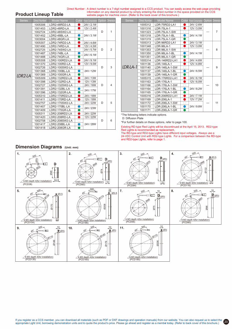
Existing RD-type Red Lights will be discontinued at the April 15, 2013. RD2-type Red Lights is recommended as replacement. The RD-type and RD2-type Lights have different input voltages. Always use a 24-VDC Control Unit with RD2-type Lights. For a comparison between the RD-type and RD2-type Lights, refer to page 1.
Direct Number : A direct number is a 7-digit number assigned to a CCS product. You can easily access the web page providing information on any desired product by simply entering the direct number in the space provided on the CCS website pages for machine vision. (Refer to the back cover of this brochure.)

19
Camera
Aluminum is used as the outer material for nearly all of the
image processing LEDs systems produced by CCS. Aluminum
is a good heat conductor and
acts as a heat sink to keep the
internal temperature of the
illumination system from rising.
Heat can be a major problem
for LED illumination systems,
decreasing light intensity and
reducing the life of the LEDs.
The use of an aluminum body
helps minimize these problems.
The LDR-LA-1 is an ultra-low-angle illumination system with an ultra-thin
design of just 10 mm. The thin design means that only minimal space is
required for installation. At a working distance from the light of 5 to 10
mm, the system can emphasize edges and height variations when taking
photographs.
Compatible with Optional Diffusion Rings and Diffusion Plates
Using a Diffusion Ring or Diffusion Panel suppresses
glare and LED reflections that may be a problem when
capturing images of glossy workpieces.
Aluminum Body Also Acts as a Highly Effective Heat Sink
A flexible circuit board is fixed at the desired angle to illuminate the workpiece from a low angle.
Without Diffusion Ring
Sample Edge Detection Using a 1-Yen Coin
Light used: LDR2-132RD-LA Diffusion Ring: DF-LDR-132LA
Cross-Sectional Illustration of the LA-1 Series
Comparison of can’s dent image
With Diffusion Ring
Ideal for edge detection and highlighting scratches on glossy surfacesLow-angle illumination is ideally suited for edge detection and for emphasizing incused characters or scratches on metal surfaces.
Low-angle illumination can be used to highlight characteristic features of workpieces
Illumination structure of LDR2-132-LA
Low-angle illumination emphasizes scratches on the lens surface.
Light used: LDR2-132RD-LA
Low-angle illumination emphasizes cracks while preventing LED reflections from appearing in the photographed image.
Light used: LDR2-74RD-LA
A WD of 15 mm emphasizes printed characters.
Light used: LDR-75LA-1
Vertical Substrate
LED
10
mm
InstallationScrew Hole
Aluminum Body
LDR2-LA/LDR-LA-1 Series
Low-angle Ring Lights
This model
Special heat
dissipating enclosure
LED
Object
Examples of Low-Angle Ring Light ImagesInspection of Disposable Camera Lenses for Damage
Inspection of CD-ROM for Inner Ring Cracking
Inspection of Printed Characters on the Bottom of a Battery
Heat dissipating construction
20
Product Lineup Table
If you register as a CCS member, you can download all materials (such as PDF or DXF drawings and operation manuals) from our website. You can also request us to select the appropriate Light Unit, borrowing demonstration units and to quote the product’s price. Please go ahead and register as a member today. (Refer to back cover of this brochure.)
*The following letters indicate options.
D: Diffusion Plate
*For further details on these options, refer to page 100.
Dimension Diagrams (Unit: mm)
1. 2.
9.
3. 4.
8.7.
11.
6.5.
10.
Ø22
(Ø3)
4-M3 depth 4(for installation)
45°
(PCD38)
Ø48
18.5
300
4-M3 depth 5(for installation)
Ø4845°
(PCD60)
Ø74
19
300
(Ø3)
4-M3 depth 5(for installation)(PCD84)
Ø70
45°Ø
100
22
300
(Ø3)
4-M3 depth 5(for installation)(PCD116)
Ø96
45°
Ø132
22
300
(Ø3.5)
4-M3 depth 5(for installation)(PCD154)
Ø13
445°
22
Ø170
300
(Ø3.5)
Ø46
10
Ø75
300
(Ø3)
Ø208
22
Ø17445° Ø3.5
300
4-M3 depth 5(for installation)(PCD186)
4-M3 depth 4(for installation)(PCD56)
Ø60
300
45°
10
Ø96
(Ø3)
4-M3 depth 4(for installation)(PCD80)
Ø110
300
45°
10
Ø146
(Ø3)
4-M3 depth 4(for installation)(PCD130)
Ø140
300
45°
Ø176
10
(Ø3)
4-M3 depth 4(for installation)(PCD160)
10
Ø170
300
45°
Ø206
(Ø3)
4-M3 depth 4(for installation)(PCD190)
Model NameDirect NumberSeries Power Consumption OptionColor Dimension
12V / 2.4W
12V / 4.5W
24V / 6.1W
24V / 5.7W
24V / 4.6W
12V / 9.0W
12V / 13W
24V / 17W
24V / 16W
12V / 18W
24V / 23W
24V / 22W
12V / 22W
24V / 28W
24V / 12W
24V / 3.1W
D
D
D
D
D
D
LDR2!LA
1001453 LDR2-48RD-LA
24V / 2.1W1005306 LDR2-48RD2-LA
1001452
1003004
1001490
1005307
1002724 LDR2-48SW2-LA
LDR2-48BL-LA
LDR2-48GR-LA
LDR2-74RD-LA
LDR2-74RD2-LA
1001487
1001488
1001370
1002725 LDR2-74SW2-LA
LDR2-74BL-LA
LDR2-74GR-LA
LDR2-100RD-LA
1001368
1001369
1001398
1002726 LDR2-100SW2-LA
LDR2-100BL-LA
LDR2-100GR-LA
LDR2-132RD-LA
1001391
1001396
1001411
1002727 LDR2-132SW2-LA
LDR2-132BL-LA
LDR2-132GR-LA
LDR2-170RD-LA
1001407
1001409
1001420
1002757 LDR2-170SW2-LA
LDR2-170BL-LA
LDR2-170GR-LA
LDR2-208RD-LA
1001417
1001418
1002758 LDR2-208SW2-LA
LDR2-208BL-LA
LDR2-208GR-LA
1
2
3
4
5
6
24V / 9.1W1005308 LDR2-100RD2-LA
24V / 13W1005309 LDR2-132RD2-LA
24V / 18W1005310 LDR2-170RD2-LA
24V / 22W1005311 LDR2-208RD2-LA
Model NameDirect NumberSeries Power Consumption OptionColor Dimension
12V / 3.0W
12V / 3.0W
24V / 4.1W
12V / 4.8W
12V / 6.0W
24V / 8.2W
12V / 7.2W
24V / 9.8W
24V / 6.5W
24V / 4.1W
—
—
—
—
—
10
8
9
11
7
LDR!LA!1
1001316
1001323
1001318
1001319
1001348
1001353
1001350
1001351
1001136
1001140
1001137
1001139
1001163
1001166
1001164
1001165
1001169
1001172
1001170
1001171
LDR-75LA-1
LDR-75LA-1-SW
LDR-75LA-1-BL
LDR-75LA-1-GR
LDR-96LA-1
LDR-96LA-1-SW
LDR-96LA-1-BL
LDR-96LA-1-GR
LDR-146LA-1
LDR-146LA-1-SW
LDR-146LA-1-BL
LDR-146LA-1-GR
LDR-176LA-1
LDR-176LA-1-SW
LDR-176LA-1-BL
LDR-176LA-1-GR
LDR-206LA-1
LDR-206LA-1-SW
LDR-206LA-1-BL
LDR-206LA-1-GR
24V / 2.6W1005312 LDR-75RD2-LA1
24V / 3.1W1005313 LDR-96RD2-LA1
24V / 4.6W1005314 LDR-146RD2-LA1
24V / 6.1W1005315 LDR-176RD2-LA1
24V / 7.1W1005316 LDR-206RD2-LA1
Existing RD-type Red Lights will be discontinued at the April 15, 2013. RD2-type Red Lights is recommended as replacement. The RD-type and RD2-type Lights have different input voltages. Always use a 24-VDC Control Unit with RD2-type Lights. For a comparison between the RD-type and RD2-type Lights, refer to page 1.
Direct Number : A direct number is a 7-digit number assigned to a CCS product. You can easily access the web page providing information on any desired product by simply entering the direct number in the space provided on the CCS website pages for machine vision. (Refer to the back cover of this brochure.)

Application Examples
Installation in tight equipment spaces is also possible.
Lightweight, compact designs
lend themselves to installation
in tight equipment spaces.
Frame structure
Mounting tap holes
Installation can be achieved
with either frame mounting or
traditional mounting with tap
holes. You therefore have
the freedom to select the
installation method according
to your site environment.
Flexibility of Mounting
to Match Your Site Environment
Illumination structure of LDL2-74!30LEDs are arranged at high-density on a single flat circuit board and the work can be illuminated fromany angle as desired.
21
There are two directional pattern selections: narrow, which focuses
the light into a beam, and wide (WD), which spreads the light out over
a broad area. This selection is available over the entire lineup.
Focus Angle Characteristics of
Wide and Narrow Types
Directional Characteristics of Narrow Model
Angle (deg.)
Rela
tive ir
radia
tion s
trength
-1 -0.5 0 0.5 1
80
70
60
50
4030
20 -20-1010
-30-40
-50
-60
-70
-80
0
0.5
1
Original lens
Larger emission surface
Larger emission surface
Directional Characteristics of Wide Model
Object
(Wide Model)
This model
Camera
(Narrow Model)
This model
A Broad Range of Applications
A
A
B
B
Light Direction, Image A Light Direction, Image B
A freely adjustable light direction and angle allow these
models to handle a wide variety of applications.
Mounting brackets are available for
four different illumination directions.
For further details, refer to page 101.
The two figures shown below
demonstrate how the illumination's
axis and angle can be changed to
yield completely different images.
This becomes an issue with
workpieces with glossy surfaces or
parallel grooves, for example. Bar
Lights are adjustable
allowing you to change
the light direction and
angle to obtain the optimal
image.
Supplementing other lighting is an other possible application.
The LDL2-33!8, the smallest member
of the Series, helps you save space
*Only the wide directional pattern is available.
*The LDL2-33!8 Series provides only tap holes for installation.
For the LDL2-33!8 Series For the LDL2 SeriesAngle (deg.)
-1 -0.5 0 0.5 1
Rela
tive ir
radia
tion s
trength
80
70
60
50
4030
20 -20-1010
-30-40
-50
-60
-70
-80
0
0.5
1
Image A is washed out because the light reflects straight back
from parallel metallic grooves. Image B shows the lettering
clearly because the light reflects out of the field of view,
leaving the background dark.
Highly functional Bar LightsNew mounting methods for Installation flexibility.
LDL2 Series
Bar Lights

Product Lineup Table
22
Model NameDirect NumberSeries Power Consumption OptionColor Dimension Model NameDirect NumberSeries Power Consumption OptionColor Dimension
D.P.C.B
D.P.C.B
D.P.C.B
2
LDL2
1004646
1004647
1004648
1004649
1003702
1003705
1003704
1003703
1003706
1003709
1003708
1003707
1003710
1003713
1003712
1003711
1003714
1003717
1003716
1003715
1003718
1003721
1003720
1003719
1003722
1003725
1003724
1003723
LDL2-33X8RD
LDL2-33X8SW
LDL2-33X8BL
LDL2-33X8GR
LDL2-41X16RD
LDL2-41X16SW
LDL2-41X16BL
LDL2-41X16GR
LDL2-41X16RD-WD
LDL2-41X16SW-WD
LDL2-41X16BL-WD
LDL2-41X16GR-WD
LDL2-80X16RD
LDL2-80X16SW
LDL2-80X16BL
LDL2-80X16GR
LDL2-80X16RD-WD
LDL2-80X16SW-WD
LDL2-80X16BL-WD
LDL2-80X16GR-WD
LDL2-119X16RD
LDL2-119X16SW
LDL2-119X16BL
LDL2-119X16GR
LDL2-119X16RD-WD
LDL2-119X16SW-WD
LDL2-119X16BL-WD
LDL2-119X16GR-WD
D.P.C.B
24V / 5.7W
24V / 1.9W
D.P.B
124V / 0.8W
24V / 5.7W
24V / 3.8W
D.P.C.B
D.P.C.B
D.P.C.B
3
24V / 12W
24V / 21W
24V / 18W
Built-to-order modelsSeries Option Dimension
D.P.C.B
LDL2
Model Name
LDL2-158X16(-WD)
LDL2-197X16(-WD)
LDL2-236X16(-WD)
LDL2-275X16(-WD)
LDL2-314X16(-WD)
LDL2-353X16(-WD)
LDL2-392X16(-WD)
LDL2-431X16(-WD)
LDL2-470X16(-WD)
LDL2-509X16(-WD)
2
Emission surface size
158X16mm
197X16mm
236X16mm
275X16mm
314X16mm
353X16mm
392X16mm
431X16mm
470X16mm
509X16mm
Color Power Consumption
24V / 7.6W
24V / 9.5W
24V / 12W
24V / 14W
24V / 16W
24V / 18W
24V / 19W
24V / 21W
24V / 23W
24V / 25W
Series Option Dimension
D.P.C.B
LDL2
Model Name
LDL2-26X30(-WD)
LDL2-50X30(-WD)
LDL2-98X30(-WD)
LDL2-122X30(-WD)
LDL2-170X30(-WD)
LDL2-194X30(-WD)
LDL2-242X30(-WD)
LDL2-290X30(-WD)
LDL2-314X30(-WD)
LDL2-338X30(-WD)
LDL2-362X30(-WD)
LDL2-386X30(-WD)
LDL2-410X30(-WD)
LDL2-434X30(-WD)
LDL2-458X30(-WD)
LDL2-482X30(-WD)
LDL2-506X30(-WD)
3
Emission surface size
26X30mm
50X30mm
98X30mm
122X30mm
170X30mm
194X30mm
242X30mm
290X30mm
314X30mm
338X30mm
362X30mm
386X30mm
410X30mm
434X30mm
458X30mm
482X30mm
506X30mm
Color Power Consumption
24V / 1.9W
24V / 3.8W
24V / 7.6W
24V / 9.5W
24V / 14W
24V / 16W
24V / 19W
24V / 23W
24V / 25W
24V / 27W
24V / 29W
24V / 31W
24V / 33W
24V / 35W
24V / 37W
24V / 38W
24V / 40W
LDL2
1003726
1003729
1003728
1003727
1003730
1003733
1003732
1003731
1003734
1003737
1003736
1003735
1003738
1003741
1003740
1003739
1003742
1003745
1003744
1003743
1003746
1003749
1003748
1003747
1003750
1003753
1003752
1003751
1003754
1003757
1003756
1003755
LDL2-74X30RD
LDL2-74X30SW
LDL2-74X30BL
LDL2-74X30GR
LDL2-74X30RD-WD
LDL2-74X30SW-WD
LDL2-74X30BL-WD
LDL2-74X30GR-WD
LDL2-146X30RD
LDL2-146X30SW
LDL2-146X30BL
LDL2-146X30GR
LDL2-146X30RD-WD
LDL2-146X30SW-WD
LDL2-146X30BL-WD
LDL2-146X30GR-WD
LDL2-218X30RD
LDL2-218X30SW
LDL2-218X30BL
LDL2-218X30GR
LDL2-218X30RD-WD
LDL2-218X30SW-WD
LDL2-218X30BL-WD
LDL2-218X30GR-WD
LDL2-266X30RD
LDL2-266X30SW
LDL2-266X30BL
LDL2-266X30GR
LDL2-266X30RD-WD
LDL2-266X30SW-WD
LDL2-266X30BL-WD
LDL2-266X30GR-WD
Direct Number : A direct number is a 7-digit number assigned to a CCS product. You can easily access the web page providing information on any desired product by simply entering the direct number in the space provided on the CCS website pages for machine vision. (Refer to the back cover of this brochure.)
Dimension Diagrams (Unit: mm)
2.
3.
1. 5.5 33 (Emitting surface)
8(E
mitti
ng su
rface
)
6
2 401.2
2.2
Two, M2 option mounting holes
13
44
12 205.2
Two, M3 holes, depth: 4 (for mounting)
5.2
8
Two, M2 holes, depth: 4 (Same on opposite side.)
(for mounting)
300
300
B(Emitting surface)
20
A
6
216
(Emi
tting s
urfac
e)
10
5 9
16
10
A
A
Slot for three, M3 nuts
2x2, M3, Depth: 5
(same for opposite side) 3.5
5.5
1.2
2.5
4.7
20
Model Name
110
LDL2-26X30(RD/SW/BL/GR)
LDL2-50X30(RD/SW/BL/GR)
LDL2-74X30(RD/SW/BL/GR)
LDL2-98X30(RD/SW/BL/GR)
LDL2-122X30(RD/SW/BL/GR)
LDL2-146X30(RD/SW/BL/GR)
LDL2-170X30(RD/SW/BL/GR)
A
38
62
86
134
158
182
B
26
50
74
98
122
146
170
Model Name
LDL2-194X30(RD/SW/BL/GR)
LDL2-218X30(RD/SW/BL/GR)
LDL2-242X30(RD/SW/BL/GR)
LDL2-266X30(RD/SW/BL/GR)
LDL2-290X30(RD/SW/BL/GR)
LDL2-314X30(RD/SW/BL/GR)
LDL2-338X30(RD/SW/BL/GR)
A
206
230
254
278
302
326
350
B
194
218
242
266
290
314
338
Model Name
LDL2-362X30(RD/SW/BL/GR)
LDL2-386X30(RD/SW/BL/GR)
LDL2-410X30(RD/SW/BL/GR)
LDL2-434X30(RD/SW/BL/GR)
LDL2-458X30(RD/SW/BL/GR)
LDL2-482X30(RD/SW/BL/GR)
LDL2-506X30(RD/SW/BL/GR)
A
374
398
422
446
470
494
518
B
362
386
410
434
458
482
506
6 B(Emitting surface)
A
34
230
(Em
itting
surfa
ce)
A
17
(10)
7
5 9
10
16
A
Slot for five, M3 nuts
2x4, M3, Depth: 5
(same for opposite side) 7 3.5
5.5
1.2
2.5 4.7
20
Model Name
LDL2-41X16(RD/SW/BL/GR)
LDL2-80X16(RD/SW/BL/GR)
LDL2-119X16(RD/SW/BL/GR)
LDL2-158X16(RD/SW/BL/GR)
LDL2-197X16(RD/SW/BL/GR)
LDL2-236X16(RD/SW/BL/GR)
LDL2-275X16(RD/SW/BL/GR)
A
53
92
131
170
209
248
287
B
41
80
119
158
197
236
275
Model Name A B
LDL2-314X16(RD/SW/BL/GR)
LDL2-353X16(RD/SW/BL/GR)
LDL2-392X16(RD/SW/BL/GR)
LDL2-431X16(RD/SW/BL/GR)
LDL2-470X16(RD/SW/BL/GR)
LDL2-509X16(RD/SW/BL/GR)
326
365
404
443
482
521
314
353
392
431
470
509
If you register as a CCS member, you can download all materials (such as PDF or DXF drawings and operation manuals) from our website. You can also request us to select the appropriate Light Unit, borrowing demonstration units and to quote the product’s price. Please go ahead and register as a member today. (Refer to back cover of this brochure.)
*The peak wavelength for Red lights is 635 nm. If a sharp-cut filter is required, use
a R60 Filter (optional).
*The peak wavelength for Red lights is 635 nm. If a sharp-cut filter is required, use
a R60 Filter (optional).
Existing Bar Light LDL series was discontinued at the end of July, 2011. LDL2 series is recommended as replacement.
Ligh
t-em
ittin
g su
rface
w
idth
: 8
mm
Lig
ht-
em
ittin
g s
urf
ace
w
idth
: 1
6 m
mL
igh
t-e
mittin
g s
urf
ace
w
idth
: 1
6 m
m
Lig
ht-
em
ittin
g s
urf
ace
w
idth
: 3
0 m
mL
igh
t-e
mittin
g s
urf
ace
w
idth
: 3
0 m
m
*The LDL2-33!8 provides only the wide directional pattern.
*The optional WD suffix indicates the wide directional pattern.
The wide versions (-WD) have the same sizes.
Standard part Special order
The wide versions (-WD) have the same sizes.
*The following letters indicate options.
D: Diffusion Plate, P: Polarizing Plate, C: Cover, B: Bracket
*The following letters indicate options.
D: Diffusion Plate, P: Polarizing Plate, C: Cover, B: Bracket
*For further details on these options, refer to page 99 to 101.
*For the availability of other options, ask your CCS representative.

High-output LED Flood Lights Perfect for Large-scale WorkpiecesHigh-output LED Flood Lights Perfect for Large-scale WorkpiecesCan illuminate objects up to 2,000 mm away. Many sizes available to handle a wide range of applications.Can illuminate objects up to 2,000 mm away. Many sizes available to handle a wide range of applications.
The high output of these Flood Lights makes
long-distance illumination possible. The models with
narrow directional characteristics can illuminate objects
2,000 mm away.
Selectable Directional CharacteristicsIlluminate Objects Up to 2,000 mm Away
Examples of Flood Light Images
Ideal for Large-scale Applications
23
Two models are available with different directional characteristics: a
Narrow Model, which enables long-distance illumination, and a Wide
Model, which provides diffuse illumination over a wide area.
Lineup Includes LED Colors of Red, White, and Infrared
A wide range of colors, from visible light to infrared, is
available. (The peak emitted light wavelength of the
Infrared Flood Lights is 860 nm.)
Picking Operations with Robots Character Recognition on Cardboard
Illumination structure of HLDL2 series Many sizes are available to handle a wide range of
applications. The high output will illuminate objects up
to 2,000 mm away.
Object
Flood Light
(Wide Model)
Camera
Flood Light
(Narrow Model)
Available in Lengths from 150 mm to 1,200 mm
The design uses multiple LED boards connected
together. Lengths can be specified in increments of 150
mm. With sizes ranging from 150 mm to a maximum of
1,200 mm, these Flood Lights are suitable for a wide
range of applications.
You can specify lengths in 150-mm increments between 150 mm...
...and 1,200 mm.
Illumination Comparison Graph by Type
Narrow Model (HLDL2-450x45RD-DF-N)
Wide Model (HLDL2-450x45RD-DF-W)
Re
lativ
e irra
dia
tion
stre
ng
th (%
)
0
100
80
60
40
20
500 1,000 1,500 2,000 (mm)
Narrow Model Wide Model
Narrow Model
Wide Model
Narrow Model
Wide Model
Narrow Model
Wide Model
HLDL2-RD (red) HLDL2-SW (white) HLDL2-IR (infrared)
*The graphs provided here are for reference only. Results for individual Lights may vary.
The gaps can be checked.
Characters can be read without interference from printed patterns.
The ideal solution to replace fluorescent lights.
HLDL2-IR (infrared) HLDL2-SW (white)
Inspection of Door Assembly Gaps
HLDL2-SW (white)
Light Distribution
Characteristics
Light Distribution
CharacteristicsRelative Irradiation Distribution
-30 -20 -10 0 10 20 30
Angle (°)
(%)
0
20
40
60
80
100
Relative Irradiation Distribution
(%)
-60 -40 -20 0 20 40 60
Angle (°)
0
20
40
60
80
100
HLDL2 Series
Flood Lights

24
Specifications
24 VDC
860 nm 860 nm
- -
Infrared Infrared
Narrow Wide
“ ” is the light-emitting surface length between 150 and 1,200 mm in 150-mm increments.
Light-emitting surface length of 150 to 450 mm: SM Connector (SMR-03V-B), Light-emitting surface length of 600 to 1,200 mm: EL Connector (ELP-02V)
SM Connector (1: Anode (+), 2: NC, 3: Cathode (!)), EL Connector (1: Anode (+), 2: Cathode (!))
Natural air cooling
Temperature: 0 to 40°C, Humidity: 20% to 85% RH (with no condensation)
Temperature: !20 to 60°C, Humidity: 20% to 85% RH (with no condensation)
Aluminum base with black alumite surface
Input voltage
Peak emitted light wavelength (typ.)
Correlated color temperature (typ.)
LED color
Illumination type
1510Direct number
Connector
Polarity and signals
Cooling method
Operating temperature and humidity
Storage temperature and humidity
Case material
Model name
-
5,600 K
White
HLDL2- x45SW-DF-N
640 nm
-
Red
HLDL2- x45RD-DF-N HLDL2- x45IR-DF-N
-
5,600 K
White
HLDL2- x45SW-DF-W
640 nm
-
Red
HLDL2- x45RD-DF-W HLDL2- x45IR-DF-W
Model-specific Dimensions
Cable Lengths for EL Connectors on Models with Emitting Surface of 600 to 1,200 mmDimension Diagram (Unit: mm)
Direct Number Model Name Cable Length (n)
3000690
3000691
3000692
3000693
3000760
3000766
FCB-1-EL2
FCB-2-EL2
FCB-3-EL2
FCB-5-EL2
FCB-10-EL2
FCB-15-EL2
1 m
2 m
3 m
5 m
10 m
15 m
FCB-n-EL2 (n=1, 2, 3, 5, 10, 15)n x 1000
(Ø7.4
)
Model-specific DimensionsModel Name for Narrow Model
HLDL2-150x45RD-DF-N / SW-DF-N / IR-DF-N
HLDL2-300x45RD-DF-N / SW-DF-N / IR-DF-N
HLDL2-450x45RD-DF-N / SW-DF-N / IR-DF-N
HLDL2-600x45RD-DF-N / SW-DF-N / IR-DF-N
HLDL2-750x45RD-DF-N / SW-DF-N / IR-DF-N
HLDL2-900x45RD-DF-N / SW-DF-N / IR-DF-N
HLDL2-1050x45RD-DF-N / SW-DF-N / IR-DF-N
HLDL2-1200x45RD-DF-N / SW-DF-N / IR-DF-N
Dimension B Dimension C
162 mm
312 mm
462 mm
612 mm
762 mm
912 mm
1062 mm
1212 mm
Dimension A
(Emitting Surface)
150 mm
300 mm
450 mm
600 mm
750 mm
900 mm
1050 mm
1200 mm
165.6 mm
315.6 mm
465.6 mm
615.6 mm
765.6 mm
915.6 mm
1065.6 mm
1215.6 mm
Model Name for Narrow Model
HLDL2-150x45RD-DF-W / SW-DF-W / IR-DF-W
HLDL2-300x45RD-DF-W / SW-DF-W / IR-DF-W
HLDL2-450x45RD-DF-W / SW-DF-W / IR-DF-W
HLDL2-600x45RD-DF-W / SW-DF-W / IR-DF-W
HLDL2-750x45RD-DF-W / SW-DF-W / IR-DF-W
HLDL2-900x45RD-DF-W / SW-DF-W / IR-DF-W
HLDL2-1050x45RD-DF-W / SW-DF-W / IR-DF-W
HLDL2-1200x45RD-DF-W / SW-DF-W / IR-DF-W
Dimension B Dimension C
162 mm
312 mm
462 mm
612 mm
762 mm
912 mm
1062 mm
1212 mm
Dimension A
(Emitting Surface)
150 mm
300 mm
450 mm
600 mm
750 mm
900 mm
1050 mm
1200 mm
165.6 mm
315.6 mm
465.6 mm
615.6 mm
765.6 mm
915.6 mm
1065.6 mm
1215.6 mm
Model-specific Specifications
Dimension Diagrams (Unit: mm)
HLDL2-(Emitting surface length) x 45RD-DF-N(-W) / SW-DF-N(-W) / IR-DF-N(-W)
Light cable for models with light-emitting surface of 600 to 1,200 mm
42
A: 150 to 1,200 (Emitting surface)
B: (A+12)
(C): (B+3.6)
6
45
(Em
ittin
g s
urf
ace
)
62
8.5
194
2
2 x 2 slots for M3 nuts
(For mounting, same on opposite side)
6
8.5
9.5
18 26
43
Five slots for M5 nuts
(for mounting)
2 x 4, M4, Depth: 8
(For mounting, same on opposite side)
Light cable for models with light-emitting surface of 150 to 450 mm
17
.5
26
Use the FCB-series or FRCB-series Extension Cables for models with light-emitting surfaces of 150 to 450 mm. Refer to page 102 for information on Extension Cables.
300
300
*These Flood Lights cannot be used with Strobe Light Control Units (PTU2-3024, BB-V24S30-M, and BB-V24S30-S).
PD3-series Control Units can be used for Strobe Mode and ON/OFF Mode, and Constant Lighting Control Units (PD2 Series, BB Series, etc.) can be
used for ON/OFF light control.
*The peak emitted light wavelength of the Red Flood Lights is 640 nm. For a Sharp-cut Filter, use the optional R60 Sharp-cut Filter.
*Refer to page 99 for information on options.
Model name
HLDL2-150x45RD-DF-N
HLDL2-300x45RD-DF-N
HLDL2-450x45RD-DF-N
HLDL2-600x45RD-DF-N
HLDL2-750x45RD-DF-N
HLDL2-900x45RD-DF-N
HLDL2-1050x45RD-DF-N
HLDL2-1200x45RD-DF-N
HLDL2-150x45RD-DF-W
HLDL2-300x45RD-DF-W
HLDL2-450x45RD-DF-W
HLDL2-600x45RD-DF-W
HLDL2-750x45RD-DF-W
HLDL2-900x45RD-DF-W
HLDL2-1050x45RD-DF-W
HLDL2-1200x45RD-DF-W
14 W
28 W
42 W
56 W
70 W
84 W
98 W
111 W
14 W
28 W
42 W
56 W
70 W
84 W
98 W
111 W
Weight
390 g
770 g
1,160 g
1,540 g
1,930 g
2,310 g
2,700 g
3,080 g
300 g
590 g
880 g
1,170 g
1,460 g
1,750 g
2,040 g
2,330 g
Re
d N
arr
ow
Mo
de
lsR
ed W
ide M
odels
Model name
HLDL2-150x45SW-DF-N
HLDL2-300x45SW-DF-N
HLDL2-450x45SW-DF-N
HLDL2-600x45SW-DF-N
HLDL2-750x45SW-DF-N
HLDL2-900x45SW-DF-N
HLDL2-1050x45SW-DF-N
HLDL2-1200x45SW-DF-N
HLDL2-150x45SW-DF-W
HLDL2-300x45SW-DF-W
HLDL2-450x45SW-DF-W
HLDL2-600x45SW-DF-W
HLDL2-750x45SW-DF-W
HLDL2-900x45SW-DF-W
HLDL2-1050x45SW-DF-W
HLDL2-1200x45SW-DF-W
16 W
31 W
46 W
61 W
76 W
91 W
106 W
121 W
16 W
31 W
46 W
61 W
76 W
91 W
106 W
121 W
Weight
390 g
770 g
1,160 g
1,540 g
1,930 g
2,310 g
2,700 g
3,080 g
300 g
590 g
880 g
1,170 g
1,460 g
1,750 g
2,040 g
2,330 g
Wh
ite
Na
rro
w M
od
els
White W
ide M
odels
Model name
HLDL2-150x45IR-DF-N
HLDL2-300x45IR-DF-N
HLDL2-450x45IR-DF-N
HLDL2-600x45IR-DF-N
HLDL2-750x45IR-DF-N
HLDL2-900x45IR-DF-N
HLDL2-1050x45IR-DF-N
HLDL2-1200x45IR-DF-N
HLDL2-150x45IR-DF-W
HLDL2-300x45IR-DF-W
HLDL2-450x45IR-DF-W
HLDL2-600x45IR-DF-W
HLDL2-750x45IR-DF-W
HLDL2-900x45IR-DF-W
HLDL2-1050x45IR-DF-W
HLDL2-1200x45IR-DF-W
12 W
24 W
36 W
48 W
60 W
72 W
84 W
96 W
12 W
24 W
36 W
48 W
60 W
72 W
84 W
96 W
Weight
390 g
770 g
1,160 g
1,540 g
1,930 g
2,310 g
2,700 g
3,080 g
300 g
590 g
880 g
1,170 g
1,460 g
1,750 g
2,040 g
2,330 g
Infr
are
d N
arr
ow
Mo
de
lsIn
frare
d W
ide M
odels
If you register as a CCS member, you can download all materials (such as PDF or DXF drawings and operation manuals) from our website. You can also request us to select the appropriate Light Unit, borrowing demonstration units and to quote the product’s price. Please go ahead and register as a member today. (Refer to back cover of this brochure.)
Power consumption
(max.)
Power consumption
(max.)
Power consumption
(max.)
Direct Number : A direct number is a 7-digit number assigned to a CCS product. You can easily access the web page providing information on any desired product by simply entering the direct number in the space provided on the CCS website pages for machine vision. (Refer to the back cover of this brochure.)
Height of Wide Models Height of Narrow Models

25
—
—
—
—
2
3
4
1
24V / 9.0W
24V / 16W
24V / 20W
24V / 37W
24V / 25W
24V / 41W
24V / 25W
24V / 14W
Model NameDirect NumberSeries Power Consumption OptionColor Dimension
If you register as a CCS member, you can download all materials (such as PDF or DXF drawings and operation manuals) from our website. You can also request us to select the appropriate Light Unit, borrowing demonstration units and to quote the product’s price. Please go ahead and register as a member today. (Refer to back cover of this brochure.)
Direct Number : A direct number is a 7-digit number assigned to a CCS product. You can easily access the web page providing information on any desired product by simply entering the direct number in the space provided on the CCS website pages for machine vision. (Refer to the back cover of this brochure.)
Camera
Enhanced light intensity and larger uniform area enables more diversified applications.
The use of power LEDs and the unique illumination
structure achieves a high-intensity with uniform diffused
illumination. The HPR Series realized higher light intensity
compared with conventional diffusion ring lights and it
makes possible to use under various situations.
Radiation of High-intensity
Diffused Light
Achievement of Larger
Uniform Areas
The unique illumination structure irradiates diffused light
effectively from the LEDs. Since there is little change in the
uniform area even if the distance from the workpiece to the
Light Unit will be changed, HPR Series can be used in a wide
variety of environments and for diverse applications.
The use of power LEDs and the unique illumination structure achieves high-intensity, uniform diffused illumination.
1/2 inch sensor
f25mm
2mm
230mm
40mm
HPR-100SW
50,100,200mm
HPR Series
Ring Lights
"Brighter" "More uniform" "Easy to use" High-Power Ring Lights
Cross section structure of HPR Series
Power LED
Diffuser panel
Radiation fin
Mounted substrate
Aluminium enclosure
* This shows the relative brightness distribution when the brightest area is set at 100.
The data given here is intended for reference purposes only and is not intended to assure the
quality of the product.
230mm
LWD : 200mm
LWD : 100mm
LWD : 50mm
Uniformity data of HPR-100SW
Camera
Lens
Macro ring
WD
Field (Y direction)
Lighting
LWD
Measuring
conditions
Macroscopic image
Image of date on food product
Object
Power LED
Diffuser panel
This model
Illumination structure of HPR-100 Examples of surface-emitting ring light images
Light intensity is not adequate at a
shutter speed of 1/10,000 with the
LED diffusion ring light.
Light used: LED diffusion ring light
The surface of a workpiece is imaged
evenly and brightly with the high-power
ring light.
Light used: HPR-100SW

26
—
—
—
—
2
3
4
1
24V / 9.0W
24V / 16W
24V / 20W
24V / 37W
24V / 25W
24V / 41W
24V / 25W
24V / 14W
Model NameDirect NumberSeries Power Consumption OptionColor Dimension
If you register as a CCS member, you can download all materials (such as PDF or DXF drawings and operation manuals) from our website. You can also request us to select the appropriate Light Unit, borrowing demonstration units and to quote the product’s price. Please go ahead and register as a member today. (Refer to back cover of this brochure.)
Direct Number : A direct number is a 7-digit number assigned to a CCS product. You can easily access the web page providing information on any desired product by simply entering the direct number in the space provided on the CCS website pages for machine vision. (Refer to the back cover of this brochure.)
Light used: Fluor ring lamp
Product Lineup Table
*HPR Series cannot be used in combination with CCS Strobe Control Unit (PTU2 Series, etc.)
*The peak wavelength for Red lights is 625 nm. If a sharp-cut filter is required, use a R60 Filter (optional).
*For further details on these options, refer to page 99.
Examples of surface-emitting ring light imagesImage of letters on package bottom
Light intensity is not adequate at a shutter speed of 1/10,000 with the fluor ring lamp.
Light used: LED diffusion ring light
Image of characters on mobile phone box
Light intensity is not adequate at a shutter speed of 1/4,000 with the LED diffused ring light.
Light used: HPR-250RD
Light intensity is adequate at the shutter speed of 1/4,000 with the HPR-250RD (red).
Light used: HPR-100RD
Light intensity is adequate at the shutter speed of 1/10,000 with the HPR-100RD (red).
1. 2.
(25.5)
26.4
300
4-M4 depth 5
45
26.4
(25.5)
300
4-M4 depth 5
45
Dimension Diagrams (Unit: mm)
Ø108Ø158
Ø 6
6
Ø116
Ø116
Ø166
3. 4.4-M4 depth 6
Ø258
Ø266
Ø210
Ø180
(18)
18.9
45
°
45
°
300 300
4-M6 depth 6
Ø412
Ø424
Ø360
Ø330
(18)19.2
HPR
1002932
1002931
1002933
1002938
1002937
1002939
1003206
1003205
1003207
1003209
1003208
1003210
HPR-100RD
HPR-100SW
HPR-100BL
HPR-150RD
HPR-150SW
HPR-150BL
HPR-250RD
HPR-250SW
HPR-250BL
HPR-400RD
HPR-400SW
HPR-400BL
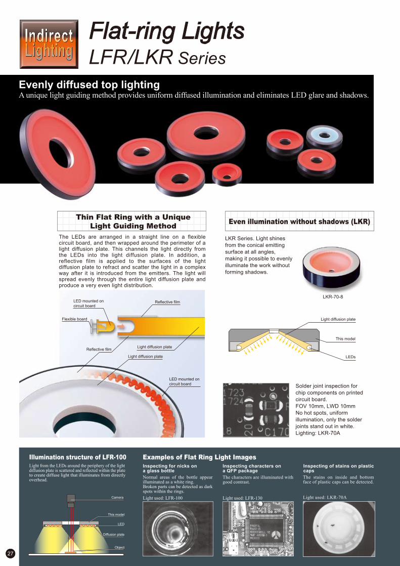
27
Camera
The LEDs are arranged in a straight line on a flexible circuit board, and then wrapped around the perimeter of a light diffusion plate. This channels the light directly from the LEDs into the light diffusion plate. In addition, a reflective film is applied to the surfaces of the light diffusion plate to refract and scatter the light in a complex way after it is introduced from the emitters. The light will spread evenly through the entire light diffusion plate and produce a very even light distribution.
Thin Flat Ring with a Unique
Light Guiding Method
A unique light guiding method provides uniform diffused illumination and eliminates LED glare and shadows.
LFR/LKR Series
Flat-ring Lights
Evenly diffused top lighting
Even illumination without shadows (LKR)
LKR Series. Light shines
from the conical emitting
surface at all angles,
making it possible to evenly
illuminate the work without
forming shadows.
Solder joint inspection for
chip components on printed
circuit board.
FOV 10mm, LWD 10mm
No hot spots, uniform
illumination, only the solder
joints stand out in white.
Lighting: LKR-70A
LKR-70-8
This model
LEDs
Light diffusion plate
Light diffusion plate
Light diffusion plate
LED mounted on
circuit board
Reflective film
LED mounted on
circuit board
Flexible board
Reflective film
Illumination structure of LFR-100Light from the LEDs around the periphery of the light diffusion plate is scattered and reflected within the plate to create diffuse light that illuminates from directly overhead.
Object
LED
Diffusion plate
This model
Examples of Flat Ring Light Images
The characters are illuminated with good contrast.
Light used: LFR-130
Inspecting for nicks on a glass bottle
Inspecting characters on a QFP package
Normal areas of the bottle appear illuminated as a white ring.Broken parts can be detected as dark spots within the rings.
Light used: LFR-100
Inspecting of stains on plastic caps
The stains on inside and bottom face of plastic caps can be detected.
Light used: LKR-70A

28
Product Lineup Table
If you register as a CCS member, you can download all materials (such as PDF or DXF drawings and operation manuals) from our website. You can also request us to select the appropriate Light Unit, borrowing demonstration units and to quote the product’s price. Please go ahead and register as a member today. (Refer to back cover of this brochure.)
Dimension Diagrams (Unit: mm)
1. 2.
9. 10.
3. 4.
8.7.6.5.
*The light emitting surfaces of LFR-100SW2/-BL/-GR are Ø77.
*The light emitting surfaces of LFR-200SW2/-BL/-GR are Ø193.
*The light emitting surfaces of LFR-100KSW2/-BL/-GR are Ø78.
*The light emitting surfaces of LFR-250SW2/-BL/-GR are Ø246.
*The light emitting surfaces of LFR-130KSW2/-BL/-GR are Ø99.
*The light emitting surfaces of LKR-70-8SW2/-BL/-GR are Ø49.2.
Ø50(Emitting surface)
Ø20
(Ø3)
300
(for installation)
4-M3 depth 5
3636
18
Ø74
Ø50(Emitting surface)
(Ø3)
300
(for installation)
4-M3 depth 5
36
Ø8
36
18
Ø74
Ø100(E
mitting
surfa
ce)
(Ø3)
Ø25
(for installation)4-M3 depth 6 (PCD70)
26
Ø125
Ø80(E
mitting
surfa
ce)Ø33
(Ø3) 300
(for installation)4-M3 depth 4 (PCD70)
(for installation)4-M3 depth 4 (PCD70)
12
Ø102
Ø80(E
mitting
surfa
ce)
(Ø3)
300
Ø33 Ø102
17
Ø103(E
mitting
surfa
ce)
(Ø3)
Ø44
300
(for installation)4-M3 depth 4 (PCD70)
12
Ø125
(Ø3)
Ø44
Ø101(E
mitting s
urface
)
300
(for installation)
4-M3 depth 4 (PCD70)
Ø123
17
(Ø3)
300
(for installation)
4-M3 depth 4 (PCD100)
Ø70
12
Ø216
Ø194(E
mitting s
urfac
e)
Ø12
0
(Ø3
.5)
300
(for installation)4-M4 depth 4 (PCD150)
12
Ø272
Ø250(Emittin
g surf
ace)
Ø330(E
mitting s
urfac
e)Ø
220
(Ø3
.5)
300
(for installation)
4-M4 depth 5 (PCD250)
12
Ø356
Model NameDirect NumberSeries OptionColor DimensionPower Consumption
—
—
—
—
—
—
—
7
5
1
3
2
6
4
LFR
1001715
1004300
1001720
1001723
1001728
1004301
1001730
1001731
1001740
1004302
1001745
1001746
1001750
1004303
1001751
1001752
1001757
1004304
1001758
1001762
1004305
1001764
1001765
1001768
LFR-100
LFR-100SW2
LFR-100-BL
LFR-100-GR
LFR-100K
LFR-100KSW2
LFR-100K-BL
LFR-100K-GR
LFR-130
LFR-130SW2
LFR-130-BL
LFR-130-GR
LFR-130K
LFR-130KSW2
LFR-130K-BL
LFR-130K-GR
LFR-200
LFR-200SW2
LFR-200-BL
LFR-250
LFR-250SW2
LFR-250-BL
LFR-250-GR
LFR-330 12V / 14W
12V / 3.6W
12V / 3.6W
12V / 9.0W
24V / 14W
24V / 13W
24V / 4.9W
24V / 4.6W
12V / 4.5W
24V / 11W
24V / 4.9W
24V / 4.6W
24V / 6.2W
24V / 5.7W
12V / 4.5W
24V / 6.1W
24V / 5.7W
12V / 8.1W
1005534 LFR-100RD2 24V / 3.6W
1005535 LFR-100RD2-K 24V / 3.6W
1005536 LFR-130RD2 24V / 4.6W
1005537 LFR-130RD2-K 24V / 4.6W
1005538 LFR-200RD2 24V / 8.1W
1005539 LFR-250RD2 24V / 11W
1005540 LFR-330RD2 24V / 14W
Model NameDirect NumberSeries Power Consumption OptionColor Dimension
—
—
—
9
10
812V / 3.0W
12V / 3.0W
24V / 4.1W
24V / 3.8W
12V / 4.5W
24V / 6.1W
24V / 5.7W
24V / 4.1W
24V / 3.8W
1002082 LKR-70A
24V / 2.6W1005531 LKR-70RD2
1002085
1002087
1002077
1004205 LKR-70SW2
LKR-70A-BL
LKR-70A-GR
LKR-70-8
1002078
1002079
1002063
1004204 LKR-70-8SW2
LKR-70-8-BL
LKR-70-8-GR
LKR-125
1002066
1002067
1004203 LKR-125SW2
LKR-125-BL
LKR-125-GR
LKR
24V / 2.6W1005530 LKR-70-8RD2
24V / 4.6W1005532 LKR-125RD2
Existing RD-type Red Lights will be discontinued at the April 15, 2013. RD2-type Red Lights is recommended as replacement. The RD-type and RD2-type Lights have different input voltages. Always use a 24-VDC Control Unit with RD2-type Lights. For a comparison between the RD-type and RD2-type Lights, refer to page 1.
Direct Number : A direct number is a 7-digit number assigned to a CCS product. You can easily access the web page providing information on any desired product by simply entering the direct number in the space provided on the CCS website pages for machine vision. (Refer to the back cover of this brochure.)

The entire outer surface of the square-shaped pack is uniformly illuminated.
Light used: FPQ2-96RD
The 20 x 20-mm compact size of this Light Unit makes it
perfect for chip parts, integrated circuits, and other extremely
small parts.
High-output Low-angle Light Unit
This square-shaped Light Unit was developed with a high
shutter speed and low angle, while still maintaining a high
output.
Select from six sizes: 20 x 20 mm, 32 x 32 mm, 48 x 48 mm, 75 x 75 mm, 96 x 96 mm, or 120 x 120 mm. There is a selection of
three LED light colors: red, white, and blue. The lineup offers 18 size and color combinations.
Perfect Compact Size for
Extremely Small Parts
Illumination structure of FPQ2-96 Examples of low-angle Square Light images
Imaging Exterior of Food Packs The lead of the IC is uniformly illuminated Imaging Exterior of Food ProductsThe object is illuminated from a low angle by uniform diffuse light through the light conduction plate.
Camera
This model
Light
conduction
plate
Object
FPQ2 Series
FPQ2-20 Series FPQ2-32 Series FPQ2-48 Series FPQ2-75 Series FPQ2-96 Series FPQ2-120 Series
FPQ2-20RD
FPQ2-20SW
FPQ2-20BL
29
Low-angle, diffuse illumination enables characters and defects to be uniformly illuminated with no LED glare.
Even, diffused side lighting
FPQ2 series(Red)Previous Model:FPQ series(Red)
Shutter speed: 1/1,000 sec.Light intensity: 100% dimming
Shutter speed: 1/1,000 sec.Light intensity: 100% dimming
A Lineup of Light Units for a Wide Range of Applications
The lead of the IC is uniformly illuminated.
Light Unit used: FPQ2-75SW
Even the entire surface of this rounded shape is illuminated uniformly.
Light used: FPQ2-75SW
Light used: FPQ2-20SW
Imaging example: Imaging exterior of a coil
The entire
outer surface
of the coil is
irradiated
uniformly.
Small coilWorkpiece
Field of View: 2.4x1.8mm
Low-angle Square Lights
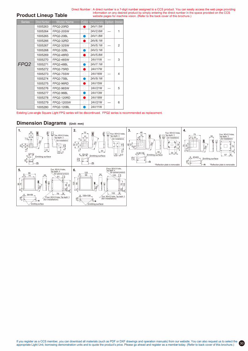
30
FPQ2-96RD
FPQ2-96SW
FPQ2-96BL
FPQ2-120RD
FPQ2-120SW
FPQ2-120BL
—
—
—
2
3
1
—
—
—
5
6
4
24V/6.1W
24V/1.8W
24V/3.1W
24V/5.1W
24V/2.6W
24V/1.5W
24V/17W
24V/7.1W
24V/9.1W
24V/16W
24V/11W
24V/5.8W
24V/18W
24V/13W
24V/11W
24V/21W
24V/21W
24V/15W
Product Lineup Table
Model Name Direct Number Series Power Consumption Option Color Dimension
If you register as a CCS member, you can download all materials (such as PDF or DXF drawings and operation manuals) from our website. You can also request us to select the appropriate Light Unit, borrowing demonstration units and to quote the product’s price. Please go ahead and register as a member today. (Refer to back cover of this brochure.)
Dimension Diagrams (Unit: mm)
1. 2. 3. 4.
6. 5.
FPQ2
1005263
1005264
1005265
1005266
1005267
1005268
1005269
1005270
1005271
1005272
1005273
1005274
1005275
1005276
1005277
1005278
1005279
1005280
FPQ2-20RD
FPQ2-20SW
FPQ2-20BL
FPQ2-32RD
FPQ2-32SW
FPQ2-32BL
FPQ2-48RD
FPQ2-48SW
FPQ2-48BL
FPQ2-75RD
FPQ2-75SW
FPQ2-75BL
4 12!12
( 8 )
Emitting surface
7.5
20
5
300
5
20
7.5
23 14
14
3
3
Two, M3!0.5 holes, Tap depth: 3
(for installation)
30
10
11
10
11
300
32
32
6
( 15 )
20 ! 20 Emitting surface
8.5
15
15 8.5
Four, M3!0.5 holes, Tap depth: 3
(for installation)
(15)
6 36!36Emitting surface
30
10
19
300
48
4819
10
30 9
930
Four, M3!0.5 holes, Tap depth: 3
(for installation)30
(15)
6 63!63Emitting surface
3007
5
75
27.5
20
27.5 20
957
57 9
Four, M3!0.5 holes, Tap depth: 3
(for installation)
96
11 74
300
96
11
74
(15)
6 84!84
Emitting surface
307.5
25
78
978
9
81
46
Four, M3!0.5 holes, Tap depth: 3(for installation)
Four, M2!0.4 holes, Tap depth: 4
(for optional product)
6 108!108
(15)
Emitting surface
3011
11 3
00
120
120
98
98
7.5
9
102
102
9
105
25
70
Four, M3!0.5 holes, Tap depth: 3(for installation)
Four, M2!0.4 holes, Tap depth: 4
(for optional product)
Existing Low-angle Square Light FPQ series will be discontinued. FPQ2 series is recommended as replacement.
*Reflection plate is removable *Reflection plate is removable
Direct Number : A direct number is a 7-digit number assigned to a CCS product. You can easily access the web page providing information on any desired product by simply entering the direct number in the space provided on the CCS website pages for machine vision. (Refer to the back cover of this brochure.)

31
Camera
White, blue, and green colors are supported along with red.
By selecting the illumination color to match the material and
color of the work, a higher level of detection precision is
possible.
Selectable lighting colors
for optimal images
—
—
—
2
3
1
12V / 6.0W
12V / 9.3W
24V / 13W
24V / 12W
12V / 13W
24V / 17W
24V / 16W
24V / 8.2W
24V / 7.6W
—
—
—
—
—
7
5
6
8
4
12V / 1.2W
12V / 2.4W
24V / 3.3W
24V / 3.1W
12V / 3.6W
12V / 4.8W
24V / 6.5W
24V / 6.1W
12V / 6.0W
24V / 8.2W
24V / 7.6W
24V / 4.9W
24V / 4.6W
24V / 1.6W
12V / 1.5W
D.P.A
Diffused Lighting from Four Sides
of the Square Case
To capture the image of
rectangular workpiece uniformly
such as a BGA or QFP, the four
corners of the workpiece would be
too close to the lighting if a round
array is used. For this type of
application, the rectangular FPQ
Series is ideal.
Low-angle, diffuse illumination enables characters and defects to be uniformly illuminated with no LED glare.
FPR Series FPQ Series
Low-angle Ring Lights Low-angle Square Lights
Even, diffused side lighting
30mm
230mm
Even diffuse light enables
optimal imaging
The image will vary depending on the distance between
the workpiece and the light (light-workpiece distance = LWD)
even when the light is the same.
It is key to successful image processing to find the best
illumination according to the surface state and the content
of inspection.
Inspection of engraved letters on metal surface (Lighting: FPR-136)
Imaging with LWD 30mm Imaging with LWD 230mm
Illumination from a low angle highlights the engraved letters white.
With diffuse light illuminated from LWD 230mm, the entire area is imaged in bright field.
Example of image using FPQ
Light conduction plate
Reflection film
LED
Reflection film
Illumination structure of FPR-100The object is illuminated from a low angle by uniform diffuse light through the light conduction plate.
Examples of low-angle Ring Light images
Light used: FPQ-96-BLLight used: FPQ-96
Inspecting a BGA solder balls
This model
LED
Object
Inspecting SOP leads in embossed tape
There is minimal glare from the sides of the embossed tape.
Blue light is used to eliminate the background gold pattern and to enhance the visibility of the solder balls.
Red Blue
Light used: FPQ-48

32
—
—
—
2
3
1
12V / 6.0W
12V / 9.3W
24V / 13W
24V / 12W
12V / 13W
24V / 17W
24V / 16W
24V / 8.2W
24V / 7.6W
—
—
—
—
—
7
5
6
8
4
12V / 1.2W
12V / 2.4W
24V / 3.3W
24V / 3.1W
12V / 3.6W
12V / 4.8W
24V / 6.5W
24V / 6.1W
12V / 6.0W
24V / 8.2W
24V / 7.6W
24V / 4.9W
24V / 4.6W
24V / 1.6W
12V / 1.5W
D.P.A
Product Lineup Table
If you register as a CCS member, you can download all materials (such as PDF or DXF drawings and operation manuals) from our website. You can also request us to select the appropriate Light Unit, borrowing demonstration units and to quote the product’s price. Please go ahead and register as a member today. (Refer to back cover of this brochure.)
Dimension Diagrams (Unit: mm)
1. 2. 3. 4.
8.7.6.5.
120120
98
98
102
102
108
30300
4-M3
15(Emitting surface)
96
96
74
74
78
78
84
30300
4-M3 15(Emitting surface)32
15(Emitting surface)
20
30
15
32
15
10
10
300
4-M3
Reflection plate
75
75
57
57
63
30
53
53
20
20
300
4-M3
15(Emitting surface)
Reflection plate
48
36
30
30
48
30
26
26
10
10
300
4-M315(Emitting surface)
300
(Ø3)
Ø73
Ø100
40
(for installation)4-M3 depth 4 (PCD84)
(Ø92
)(Emitti
ng su
rface
)
(Ø12
6)(Em
itting
surfa
ce)
Ø10
9
300
(for installation)4-M3 depth 4 (PCD120)
Ø136
40
(Ø3)
(Ø17
0)(Em
itting
surfa
ce)
Ø15
3300
(for installation)4-M3 depth 4 (PCD164)
Ø180
40
(Ø3)
*Reflection plate is removable *Reflection plate is removable
Model NameDirect NumberSeries Power Consumption OptionColor Dimension Model NameDirect NumberSeries Power Consumption OptionColor Dimension
—
—
—
2
3
112V / 6.0W
12V / 9.3W
24V / 13W
24V / 12W
12V / 13W
24V / 17W
24V / 16W
24V / 8.2W
24V / 7.6W
1000083 FPR-100
1000084
1000085
1000093
1004200 FPR-100SW2
FPR-100-BL
FPR-100-GR
FPR-136
1000094
1000095
1000101
1004201 FPR-136SW2
FPR-136-BL
FPR-136-GR
FPR-180
1000103
1000104
1004202 FPR-180SW2
FPR-180-BL
FPR-180-GR
FPR
12V / 1.2W
12V / 2.4W
24V / 3.3W
24V / 3.1W
12V / 3.6W
12V / 4.8W
24V / 6.5W
24V / 6.1W
12V / 6.0W
24V / 8.2W
24V / 7.6W
24V / 4.9W
24V / 4.6W
24V / 1.6W
—
—
—
—
—
7
5
6
8
4
1000037 FPQ-3224V / 6.1W1005544 FPR-100RD2
1000040
1000041
1000047
1004187 FPQ-32SW2
FPQ-32-BL
FPQ-32-GR
FPQ-48
1000049
1000050
1000059
1004188 FPQ-48SW2
FPQ-48-BL
FPQ-48-GR
FPQ-75
1000060
1000062
1000074
1004189 FPQ-75SW2
FPQ-75-BL
FPQ-75-GR
FPQ-96
1000075
1000076
1000031
1004190 FPQ-96SW2
FPQ-96-BL
FPQ-96-GR
FPQ-120
1000032
1004191 FPQ-120SW2
FPQ-120-BL
FPQ
24V / 9.1W1005545 FPR-136RD2
24V / 13W1005546 FPR-180RD2 Scheduled for discontinuation of production
Existing Low-angle Square Light FPQ series will be discontinued at the April 15,
2013. FPQ2 series is recommended as replacement.
Existing RD-type Red Lights will be discontinued at the April 15, 2013. RD2-type Red Lights is recommended as replacement. The RD-type and RD2-type Lights have different input voltages. Always use a 24-VDC Control Unit with RD2-type Lights. For a comparison between the RD-type and RD2-type Lights, refer to page 1.
Direct Number : A direct number is a 7-digit number assigned to a CCS product. You can easily access the web page providing information on any desired product by simply entering the direct number in the space provided on the CCS website pages for machine vision. (Refer to the back cover of this brochure.)

Illumination structure of TH-140!105 Examples of Flat light Images
Imaging Plastic Containers for Defect Inspections
33
By redesigning the optical system and improving illumination
efficiency we created a flat light with unprecedented high output.
New Diffusing Plate with Anti-Reflection EffectHigh-output Flat Lights
Broad Selection
There are over 11 emitting surface sizes ranging from the
smallest at 27 mm ! 27 mm to the largest at 211 mm ! 200 mm.
LED colors are available in red, white, or blue.
The increased lineup now includes 33 different size and color
combinations.
Previous model:LDL-TP(Red) TH series(Red)
Shutter speed: 1/10,000 sec.Light intensity: 100% dimming
Shutter speed: 1/10,000 sec.Light intensity: 100% dimming
No matte coating
With matte coating
TH series
Previously, there were cases in
which the camera lens was
subject to secondary reflections
which caused glare to appear on the
image. For the TH series, the matte
c o a t i n g o n t h e
s u r f a c e o f t h e
d i f f u s i o n p l a t e
eliminates light
reflections.
Flexibility of Mounting to Match Your Site Environment
Frame Structure
Nut Insertion Slot
Mounting is possible with
frames or with tap holes
on the bottom.
You therefore have the
freedom to select the
installation method
according to your site
environment.
Mounting Tapped Hole
M3 Screw and Nut
(Not included)
A high output is achieved with a flat design.You can illuminate the workpiece from the back, through a Diffusion Plate.
Can check for lid deformations and the quality of the seal of the transparent case.
Light used: TH-140x105RD
Sharply captures the liquid level.
Light used: TH-200x150RD
Imaging Plastic Bottle Liquid Levels
Example using Light Control (LC) Film
On the left side, light diffraction occurs. On the right side, the outline is accurately inspected.
Without LC film With LC film
Imaging Exterior of Metal Rods
High output and High Uniformity
TH Series
Flat Lights
Previous model:LDL-TP
Previous model:LDL-TP TH series
The ambient light isreflecting on thediffusing plate.
The matte coatingprevents thereflection.
Ideal for silhouette inspection.
On-chip LEDs
Object
This model
Camera
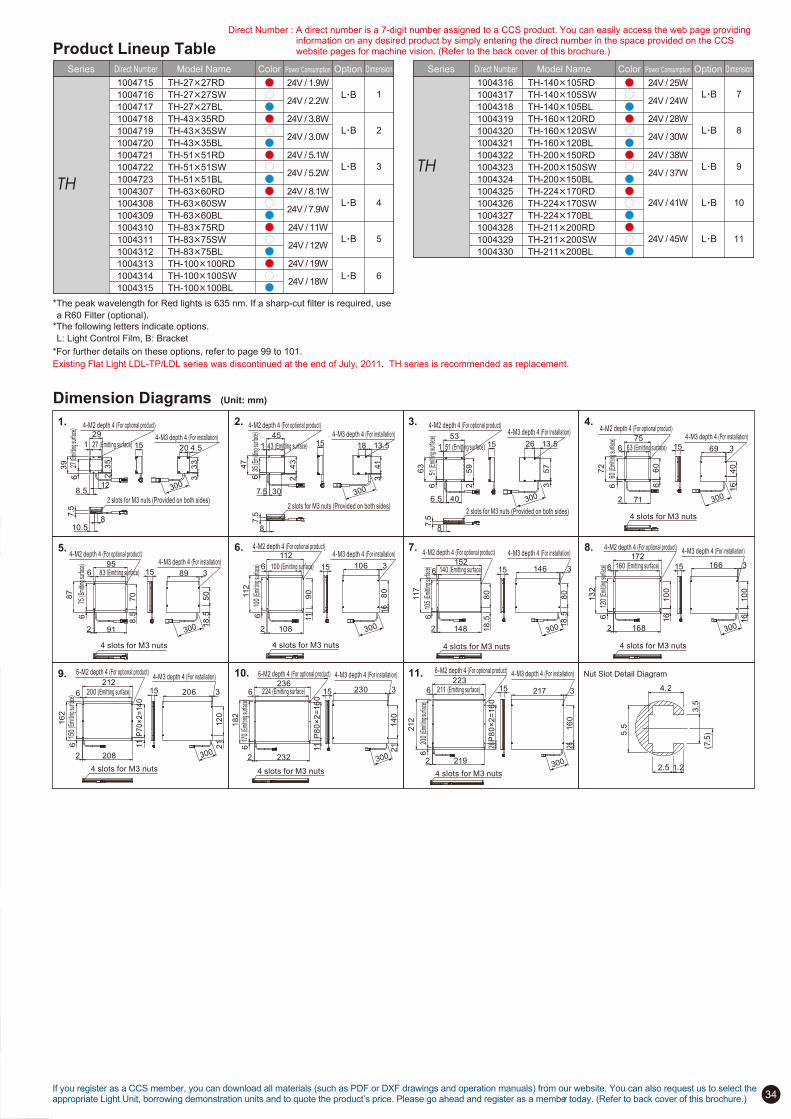
34
Product Lineup TableModel NameDirect NumberSeries Power Consumption OptionColor Dimension
L.B
L.B
L.B
L.B
L.B
4
5
L.B 6
1
2
3
TH
1004715
1004716
1004717
1004718
1004719
1004720
1004721
1004722
1004723
1004307
1004308
1004309
1004310
1004311
1004312
1004313
1004314
1004315
TH-27X27RD
TH-27X27SW
TH-27X27BL
TH-43X35RD
TH-43X35SW
TH-43X35BL
TH-51X51RD
TH-51X51SW
TH-51X51BL
TH-63X60RD
TH-63X60SW
TH-63X60BL
TH-83X75RD
TH-83X75SW
TH-83X75BL
TH-100X100RD
TH-100X100SW
TH-100X100BL
24V / 1.9W
24V / 2.2W
24V / 3.8W
24V / 3.0W
24V / 5.1W
24V / 5.2W
24V / 8.1W
24V / 7.9W
24V / 11W
24V / 12W
24V / 19W
24V / 18W
Model NameDirect NumberSeries Power Consumption OptionColor Dimension
L.B
L.B
L.B
L.B
L.B
10
11
7
8
9TH
1004316
1004317
1004318
1004319
1004320
1004321
1004322
1004323
1004324
1004325
1004326
1004327
1004328
1004329
1004330
TH-140X105RD
TH-140X105SW
TH-140X105BL
TH-160X120RD
TH-160X120SW
TH-160X120BL
TH-200X150RD
TH-200X150SW
TH-200X150BL
TH-224X170RD
TH-224X170SW
TH-224X170BL
TH-211X200RD
TH-211X200SW
TH-211X200BL
24V / 25W
24V / 24W
24V / 28W
24V / 30W
24V / 38W
24V / 37W
24V / 41W
24V / 45W
612
0 (E
mittin
g sur
face)
13
2
6 160 (Emitting surface)172
2 168
16
10
0
4-M2 depth 4 (For optional product)
15
16
10
0
3166
4-M3 depth 4 (For installation)
4 slots for M3 nuts
Dimension Diagrams (Unit: mm)
3.2. 4.
5.
1.
7.6. 8.
9. 11. Nut Slot Detail Diagram10.
4-M2 depth 4 (For optional product)29
1 27 (Emitting surface)
39
6 2
7 (E
mittin
g sur
face)
8.512
23
5
15 4.520
33
3
10.58
2 slots for M3 nuts (Provided on both sides)
4-M3 depth 4 (For installation)
7.5
300
4-M2 depth 4 (For optional product)
13.5
4-M3 depth 4 (For installation)45
1 43 (Emitting surface)
47
635
(Emi
tting s
urfac
e)
7.5 30
24
3
15
8
18
341
2 slots for M3 nuts (Provided on both sides)
7.5
300
53
1 51 (Emitting surface)
63
651
(Emi
tting s
urfac
e)
6.5 40
25
9
4-M2 depth 4 (For optional product)
15 13.526
35
7
4-M3 depth 4 (For installation)
8
2 slots for M3 nuts (Provided on both sides)
7.5
300
660
(Emi
tting s
urfac
e)
72
6 63 (Emitting surface)
75
2 71
66
0
4-M2 depth 4 (For optional product)
15 369
16
40
4-M3 depth 4 (For installation)
4 slots for M3 nuts
300
675
(Emi
tting s
urfac
e)
87
6 83 (Emitting surface)95
2 91
8.5
70
4-M2 depth 4 (For optional product)
15 389
18
.55
0
4-M3 depth 4 (For installation)
4 slots for M3 nuts
300
610
0 (E
mittin
g sur
face)
112
6 100 (Emitting surface)
112
2 108
11
90
4-M2 depth 4 (For optional product)
15
16
80
3106
4-M3 depth 4 (For installation)
4 slots for M3 nuts
300
610
5 (E
mittin
g sur
face)
117
6 140 (Emitting surface)152
2 148 18
.58
0
4-M2 depth 4 (For optional product)
1518
.58
03146
4-M3 depth 4 (For installation)
4 slots for M3 nuts
300 300
615
0 (E
mittin
g sur
face)
16
2
6 200 (Emitting surface)
212
2 208
11
P7
0!
2=
14
0
6-M2 depth 4 (For optional product)
15
21
12
0
3206
4-M3 depth 4 (For installation)
4 slots for M3 nuts
300
617
0 (E
mittin
g sur
face)
18
2
6 224 (Emitting surface)236
2 232
11
P8
0!
2=
16
0
6-M2 depth 4 (For optional product)
15
21
14
0
3230
4-M3 depth 4 (For installation)
4 slots for M3 nuts
300
620
0 (E
mittin
g sur
face)
212
6 211 (Emitting surface)223
2 219
26P
80!
2=
16
0
6-M2 depth 4 (For optional product)
15
2616
0
3217
4-M3 depth 4 (For installation)
4 slots for M3 nuts300
(7.5
)
3.5
4.2
5.5
1.22.5
If you register as a CCS member, you can download all materials (such as PDF or DXF drawings and operation manuals) from our website. You can also request us to select the appropriate Light Unit, borrowing demonstration units and to quote the product’s price. Please go ahead and register as a member today. (Refer to back cover of this brochure.)
*The peak wavelength for Red lights is 635 nm. If a sharp-cut filter is required, use
a R60 Filter (optional).
*The following letters indicate options.
L: Light Control Film, B: Bracket
*For further details on these options, refer to page 99 to 101.
Existing Flat Light LDL-TP/LDL series was discontinued at the end of July, 2011. TH series is recommended as replacement.
Direct Number : A direct number is a 7-digit number assigned to a CCS product. You can easily access the web page providing information on any desired product by simply entering the direct number in the space provided on the CCS website pages for machine vision. (Refer to the back cover of this brochure.)

35
Camera
The use of a unique CCS light-guiding method realized to
irradiate uniform diffused light.
Lightweight, Thin Design with
Low Power Consumption
Varied Selection
Flat Lights with UniqueLight-guiding Technology
A wide variety of sizes and colors are available to use for
various applications. Models with a mounting panel (P) for
installing lights are also available.
With a thin design allows installing this light in any place.
Allocated LEDs are fixed around the periphery of the Diffusion
Plate with a transparent fixing material. This unique structure
makes more complex to reflect and scatter the light from LEDs
and it makes possible to irradiate uniform diffused light from
flat light emitting surface.
Power-saving Flat Lights with a compact design.
Flat LightsLFL Series
Silhouette inspection of an object using uniform lighting
Diffusion cover
Light diffusion plate
Diffusion sheet
Special printed pattern
Reflective sheet
Aluminum body
LFL-100Inspecting for defects in rectangular PET bottles
Inspecting the level of a liquid inbottles
Illumination Structure of LFL-100
LED
Object
This model
Examples of Flat-light imagesLight from the LEDs that are arranged around the periphery of the light diffusion plate passes through the plate to produce uniform illumination. Image as seen with the human eye
in normal light.The entire object is evenly illuminated without shadows; however, internal parts are also being imaged and it makes inspection difficult.
Light used: FPR-136
The entire object is evenly illuminated and the printed surface stands out clearly.
Light used: LFL-100
Inspecting printing on tape cassettes

36
Product Lineup Table
If you register as a CCS member, you can download all materials (such as PDF or DXF drawings and operation manuals) from our website. You can also request us to select the appropriate Light Unit, borrowing demonstration units and to quote the product’s price. Please go ahead and register as a member today. (Refer to back cover of this brochure.)
Dimension Diagrams (Unit: mm)
1. 2. 3. 4.
8.7.
9.
6.
11.10.
5.
(Ø3)
25(Emitting surface)
(0.8)
(38)
(6)
(0.5)
(0.5
)
(42)
(45)
(26)
25(E
mitti
ng su
rface
)
2-Ø3.5(for installation)
300
155.5
25(Emitting surface)
(Ø3)
(0.5)
(0.5
)
(38)
(6)
(26)
300
25(E
mitt
ing
surfa
ce)
30(E
mitt
ing
surfa
ce)
2-Ø3.5
(for installation)
(42)
(Ø3) (53)
(0.5
)
(0.5)
(43)
(7)
(0.8)
300
48
306
41(Emitting surface)
2-Ø3.5
(for installation)
(Ø3)
(66)
(81)
(58)
(7)
(0.8)
56(Emitting surface)
45(E
mitt
ing
surfa
ce)
300
4
60 (Ø3) (95)
(0.8)
(66)
(7)
(74)
2-Ø3.5
(for installation)
70(Emitting surface)
53(E
mitt
ing
surfa
ce)
300
60
4
(72)
50(Emitting surface)
(72)
50(E
mitt
ing
surfa
ce)
56
56
4-Ø3/Ø4.8 countersink, depth2.8
(Ø3)
(for installation)
(6)
300 15.9
80(E
mitt
ing
surfa
ce)
100(Emitting surface)
4-Ø3.5/Ø6 countersink, depth3(for installation)300
120
5110
132
100
(Ø3)
8
4-Ø3.5/Ø6 countersink, depth3.5
180(Emitting surface)
300214
180
177
166
(Ø3)
5.5
17
8
135
(Em
ittin
g su
rfac
e)
(for installation)
18
0(E
mitt
ing
su
rfa
ce)
200(Emitting surface)
4-Ø3.5/Ø6 countersink, depth3.5(for installation)
300
222
212
234
20017
5 8
(Ø3)
250
(Em
itting s
urf
ace)
360(Emitting surface)
6-Ø4.5/Ø8 countersink, depth6(for installation)
300 41025 180 180
310
6298
(Ø3)
16
41(Emitting surface)
30(E
mitt
ing s
urf
ace
)
(Ø3) (43)
(42)
(6)
(0.5
)
300
(0.5)
*The following letters indicate options.
L: Light Control Film
*For further details on these options, refer to page 100.
Model NameDirect NumberSeries Power Consumption OptionColor Dimension
—
—
—
—
—
—
3
1
5
2
6
4
1001674 LFL-612 12V / 0.3W
12V / 0.3W
12V / 2.1W
24V / 2.9W
24V / 2.7W
24V / 0.4W
12V / 0.6W
24V / 2.4W
24V / 2.3W
24V / 0.4W
24V / 0.8W
12V / 0.6W
24V / 0.8W
12V / 1.8W
1001676
1001679
1001691
1004230 LFL-612SW2
LFL-612-BL
LFL-612-GR
LFL-612P
1001677
1001680
1001568
1004231 LFL-612SW2-P
LFL-612-BL-P
LFL-612-GR-P
LFL-1012
1001570
1001573
1001582
1004225 LFL-1012SW2
LFL-1012-BL
LFL-1012-GR
LFL-1012P
1001571
1001574
1001633
1004293 LFL-1012SW2-P
LFL-1012-BL-P
LFL-1012-GR-P
LFL-3212
1001634
1001635
1001640
1004232 LFL-3212SW2
LFL-3212-BL
LFL-3212-GR
LFL-4012
1001642
1001643
1004228 LFL-4012SW2
LFL-4012-BL
LFL-4012-GR
●●●●●●●●●●●●●●●●●●●●●●●●●●●●●●
Model NameDirect NumberSeries Power Consumption OptionColor Dimension
L
—
—
L
L
9
7
11
8
10
1001650 LFL-50 12V / 2.4W
12V / 4.2W
24V / 3.3W
24V / 3.1W
12V / 7.2W
24V / 40W
24V / 37W
24V / 5.7W
24V / 5.3W
24V / 12W
12V / 9.0W
24V / 9.8W
24V / 9.1W
12V / 27W
1005528 LFL-612RD2 24V / 0.6W 1005527 LFL-50RD2 24V / 2.1W
1001654
1001655
1001556
1004229 LFL-50SW2
LFL-50-BL
LFL-50-GR
LFL-100
1001558
1001559
1001597
1004226 LFL-100SW2
LFL-100-BL
LFL-100-GR
LFL-180
1001598
1001599
1001604
1004223 LFL-180SW2
LFL-180-BL
LFL-180-GR
LFL-200
1001607
1003050
1001638
1004224 LFL-200SW2
LFL-200-BL
LFL-200-GR
LFL-360
1003567
1004227 LFL-360SW2
LFL-360-BL
●●●●●●●●●●●●●●●●●●●●●●●●
LFL
LFL
24V / 0.6W1005529 LFL-612RD2-P
24V / 0.6W1005520 LFL-1012RD2
24V / 0.6W1005521 LFL-1012RD2-P
24V / 1.6W1005524 LFL-3212RD2
24V / 2.1W1005526 LFL-4012RD2
24V / 5.1W1005519 LFL-100RD2
24V / 7.1W1005522 LFL-180RD2
24V / 12W1005523 LFL-200RD2
24V / 30W1005525 LFL-360RD2
Existing RD-type Red Lights will be discontinued at the April 15, 2013. RD2-type Red Lights is recommended as replacement. The RD-type and RD2-type Lights have different input voltages. Always use a 24-VDC Control Unit with RD2-type Lights. For a comparison between the RD-type and RD2-type Lights, refer to page 1.
Direct Number : A direct number is a 7-digit number assigned to a CCS product. You can easily access the web page providing information on any desired product by simply entering the direct number in the space provided on the CCS website pages for machine vision. (Refer to the back cover of this brochure.)

Illumination structure of LFX2-100
Object
Examples of Flat-Dome Light Images
Application Examples in Packaging Application Examples in Food Industry Application Examples in Pharmaceuticals
37
High Output, uniform diffused lightReproduce the effects of both coaxial and dome illumination.
The dot pattern on the surface of the Light Guide
Diffusion Plate controls illumination diffusion and
transmission. The result is uniformly diffused light
over the workpiece. The high output also enables the
use of high-speed cameras.
On-chip LEDs
This model
Camera
The surface is uniformly lighted to inspect the edge or overlap of transparent film.
Light used: LFX2-200RD
Use these lights for a wide range of applications from visible
light to invisible infrared light. The peak wavelength for
Infrared lights is 850 nm.
The high output enables use with high-speed cameras. There
is more than enough illumination for imaging at a shutter
speed of 1/4,000.
Wavelengths from Visible Light to InfraredHigh output, uniform diffused light
Broad Lineup for Optimal Images
Models are available with five emitting surface sizes: 50, 75,
100, 150, and 200 mm. Select red, white, or infrared light.
Variety of Mounting Methods
There are a total of twelve mounting holes: four in the front
and two on each side. This selection of mounting surfaces
means better matches to your application site environment.
Infrared Light
LFX2-50RD LFX2-75RD LFX2-100RD LFX2-150IR850 LFX2-200SW
The products are uniformly lighted without showing the printed pattern on the packages.
Light used: LFX2-200RD
LFX2-100RDPrevious Model(LFX-100RD)
The output of the previous model was too low for some applications.
With the LFX2, the output is sufficient for proper imaging at a shutter speed of 1/4,000.
Red Light
The printed pattern is still visible, making it difficult to see the surface condition.
T h e p r i n t e d p a t t e r n i s completely eliminated so that the surface condition can be easily inspected.
Sides: 2 holes each
(3 each for the LFX2-200 Series)
Front: 4 holes
LFX2 Series
Flat-Dome Lights
Light is transmitted though tea leaves todetect only foreign objects.
Light used: LFX2-200IR850

38
Product Lineup TableModel NameDirect NumberSeries Power Consumption OptionColor Dimension
—
—
—
—
—
4
5
1
2
3LFX2
1004156
1004160
1004164
1004157
1004161
1004165
1004158
1004162
1004166
1004159
1004163
1004167
1004115
1004116
1004117
LFX2-50RD
LFX2-50SW
LFX2-50IR850
LFX2-75RD
LFX2-75SW
LFX2-75IR850
LFX2-100RD
LFX2-100SW
LFX2-100IR850
LFX2-150RD
LFX2-150SW
LFX2-150IR850
LFX2-200RD
LFX2-200SW
LFX2-200IR850
24V / 11W
24V / 6.1W
24V / 6.6W
24V / 11W
24V / 9.1W
24V / 14W
24V / 16W
24V / 13W
24V / 14W
24V / 21W
24V / 19W
24V / 20W
24V / 31W
24V / 25W
24V / 27W
Dimension Diagrams (Unit: mm)
3.2. 4.
5.
1.
143
143
21.5
21.5
7 129 7129
12
41.5
60
7
100
(em
ittin
g su
rface
)
100(emitting surface)
4-M4!0.7 tapped holes 6 diameter, counterbore depth: 4 (from rear) (for installation)
4!2-M4!0.7, tapped depth: 6
300
300
118
75
(em
ittin
g su
rface
)
75(emitting surface) 21.5
21.5
7 104 7104
1241.5
35
7
118
4!2-M4!0.7, tapped depth: 6 (for mounting, same on all four sides) (for mounting, same on all four sides) (for mounting, same on all four sides)
4-M4!0.7 tapped holes 6 diameter, counterbore depth: 4 (from rear) (for installation)
200
(em
ittin
g su
rface
)
200(emitting surface)
4-M5!0.8 tapped holes 8 diameter, counterbore depth: 4 (from rear) (for installation) 247
247
7 233 7233
23.5
23.5
4!3-M4!0.7, tapped depth: 6
43.5
160
12
7
300
(for mounting, same on all four sides)
12
36.5
20
74!2-M4!0.7, tapped depth: 6 (for mounting, same on all four sides)
93
93
50(emitting surface)
50
(em
ittin
g su
rface
) 21.5
7 79
779
21.5
4-M4!0.7 tapped holes 6 diameter, counterbore depth: 4 (from rear) (for installation)
300
150
(em
ittin
g su
rface
)
150(emitting surface)
4-M4!0.7 tapped holes 6 diameter, counterbore depth: 4 (from rear) (for installation) 193
21.5
21.5
193
7 179 7179
4!2-M4!0.7, tapped depth: 6
12
7
46.5
100
300
If you register as a CCS member, you can download all materials (such as PDF or DXF drawings and operation manuals) from our website. You can also request us to select the appropriate Light Unit, borrowing demonstration units and to quote the product’s price. Please go ahead and register as a member today. (Refer to back cover of this brochure.)
*The peak wavelength for Red lights is 635 nm. If a sharp-cut filter is required, use a R60 Filter (optional).
*LFX2 Flat-Dome Lights cannot be used in combination with CCS Strobe Control Unit (PTU2 Series, etc.).
*For further details on these options, refer to page 99.
Direct Number : A direct number is a 7-digit number assigned to a CCS product. You can easily access the web page providing information on any desired product by simply entering the direct number in the space provided on the CCS website pages for machine vision. (Refer to the back cover of this brochure.)
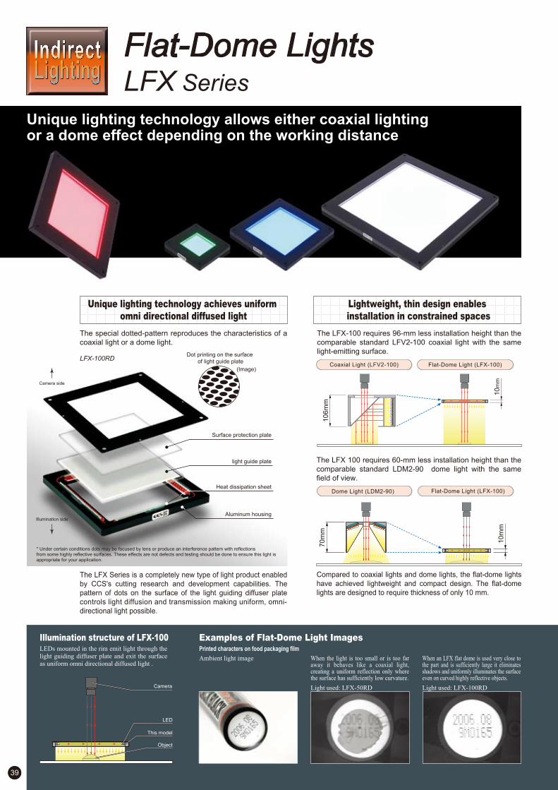
39
—
—
—
2
3
1
The special dotted-pattern reproduces the characteristics of a
coaxial light or a dome light.
Unique lighting technology allows either coaxial lighting or a dome effect depending on the working distance
LFX Series
Flat-Dome Lights
Unique lighting technology achieves uniform
omni directional diffused light
The LFX Series is a completely new type of light product enabled
by CCS's cutting research and development capabilities. The
pattern of dots on the surface of the light guiding diffuser plate
controls light diffusion and transmission making uniform, omni-
directional light possible.
LFX-100RD
Surface protection plate
light guide plate
Heat dissipation sheet
Aluminum housing
Dot printing on the surface
of light guide plate
(Image)
* Under certain conditions dots may be focused by lens or produce an interference pattern with reflections from some highly reflective surfaces. These effects are not defects and testing should be done to ensure this light is appropriate for your application.
Camera side
Illumination side
The LFX-100 requires 96-mm less installation height than the
comparable standard LFV2-100 coaxial light with the same
light-emitting surface.
The LFX 100 requires 60-mm less installation height than the
comparable standard LDM2-90 dome light with the same
field of view.
Lightweight, thin design enables
installation in constrained spaces
Compared to coaxial lights and dome lights, the flat-dome lights
have achieved lightweight and compact design. The flat-dome
lights are designed to require thickness of only 10 mm.
Coaxial Light (LFV2-100)
10
6m
m
Flat-Dome Light (LFX-100)
10
mm
Dome Light (LDM2-90) Flat-Dome Light (LFX-100)
10
mm
70
mm
Illumination structure of LFX-100 Examples of Flat-Dome Light ImagesPrinted characters on food packaging filmLEDs mounted in the rim emit light through the
light guiding diffuser plate and exit the surface
as uniform omni directional diffused light .
Camera
Object
LED
This model
Ambient light image When the light is too small or is too far away it behaves like a coaxial light, creating a uniform reflection only where the surface has sufficiently low curvature.
Light used: LFX-50RD
When an LFX flat dome is used very close to the part and is sufficiently large it eliminates shadows and uniformly illuminates the surface even on curved highly reflective objects.
Light used: LFX-100RD

40If you register as a CCS member, you can download all materials (such as PDF or DXF drawings and operation manuals) from our website. You can also request us to select the appropriate Light Unit, borrowing demonstration units and to quote the product’s price. Please go ahead and register as a member today. (Refer to back cover of this brochure.)
—
—
—
2
3
1
24V / 2.4W
24V / 6.5W
24V / 9.6W
24V / 13W
24V / 4.8W
24V / 3.3W
Product Lineup Table
Model NameDirect NumberSeries Power Consumption OptionColor Dimension
*Red (RD) LFX Lights cannot be used in combination with CCS Strobe Control Unit (PTU2 Series, etc.).
Examples of Flat-Dome Light ImagesCans lid print and features
Ambient light image With the LFX at distance of 10 mm from the light to the object the shadows from the non planar features on the lid a minimized and all but disappear.
Light used: LFX-100RD
With the LFX at distance of 85 mm from the light to the object, the light is able to highlight the significantly raised pull-tab.
Light used: LFX-100RD
With the LFX at distance of 295 mm from the light to the object, the more collimated light shows the smaller ridges in the can surface clearly.
Light used: LFX-100RD
1. 2. 3.
300
4-M4X0.7 Through tap hole 4-M4X0.7 Through tap hole 4-M5X0.8 Through tap hole
50
(Em
ittin
g su
rface
)
93
79
79
93 4-Ø6 Counter bore (from reverse), depth 4
4- 6 Counter bore (from reverse), depth 450
(Emitting surface)
10
300
200(Emitting surface)
233
247
200
(Em
ittin
g su
rface
)
233
247
10
300
100(Emitting surface)
129143
100
(Em
ittin
g su
rface
)
129
143
10
Dimension Diagrams (Unit: mm)
4-Ø6 Counter bore (from reverse), depth 4
LFX
1002059
1002060
1002057
1002058
1002050
1002051
1002048
1002049
1002055
1002056
1002052
1002053
LFX-50RD
LFX-50SW
LFX-50BL
LFX-50GR
LFX-100RD
LFX-100SW
LFX-100BL
LFX-100GR
LFX-200RD
LFX-200SW
LFX-200BL
LFX-200GR
Existing Flat-Dome Light LFX series will be discontinued at the April 15, 2013. LFX2 series is recommended as replacement.
Direct Number : A direct number is a 7-digit number assigned to a CCS product. You can easily access the web page providing information on any desired product by simply entering the direct number in the space provided on the CCS website pages for machine vision. (Refer to the back cover of this brochure.)

41
—
—
—
—
2
3
4
1
1/2 inch CCD
f12mm
0mm
122mm
50mm
HPD-150SW
25mm / 30mm / 35mm
Camera
The use of power LEDs greatly enhances the light
intensity compared with conventional dome lights. The
unique illumination structure allows for a larger uniform
area.
Enhanced light intensity and larger uniform area
broaden the use of the lights to more diverse
environments and applications.
Achievement of high-luminosity uniform diffusion light Achievement of larger uniform areas
HPD Series
Dome Lights
Images of appearance of cell phone
Enhanced light intensity and larger uniform area allows for use in more diversified applications.
"Brighter" "More uniform" "Easy to use" High-Power Dome Lights
Reflector plate
Power LED
Radiation fin
Mounted substrate
Aluminium enclosure
Cross section structure of HPD Series
122mm
Uniformity data of HPD-150SW
LWD : 35mm
LWD : 30mm
LWD : 25mm
* This shows the relative brightness distribution when the brightest area is set at 100.
The data given here is intended for reference purposes only and is not intended to assure the
quality of the product.
Camera
Lens
Macro ring
WD
Field (Y direction)
Lighting
LWD
Measuring
conditions
This model
Reflector plate
Power LED
Object
Illumination structure of HPD-150The use of power LEDs significantly enhances the light intensity compared with conventional lights. The unique illumination structure achieves a larger uniform area.
Examples of surface-emitting dome light images
Macroscopic image Unevenness occurs in the illumination
area with the 100W halogen ring lamp.
Light used: 100W halogen ring lamp
The surface of a workpiece is imaged
evenly and brightly with the high-power
dome light.
Light used: HPD-100RD

42
—
—
—
—
2
3
4
1
24V / 9.0W
24V / 16W
24V / 20W
24V / 37W
24V / 25W
24V / 41W
24V / 25W
24V / 14W
Product Lineup Table
Model NameDirect NumberSeries Power Consumption OptionColor Dimension
*HPD Series cannot be used in combination with CCS Strobe Control Unit (PTU2 Series, etc.)
*The peak wavelength for Red lights is 625 nm. If a sharp-cut filter is required, use a R60 Filter (optional).
*For further details on these options, refer to page 99.
Light used: LED ring light
Examples of surface-emitting dome light imagesImages of appearance and printed date of food product
The surface of a workpiece cannot be irradiated uniformly with the LED ring light
Light used: Diffused LED light
Images of appearance of food product
Diffused LED light is not available to have a sufficient intensity level for 1/4,000 sec of exposure time.
Light used: HPD-150SW
The surface of a workpiece is imaged evenly and brightly with the high-power dome light.
Light used: HPD-250SW
HPD-250SW has a sufficient intensity level as it is available to use even in 1/4,000 sec of exposure time.
If you register as a CCS member, you can download all materials (such as PDF or DXF drawings and operation manuals) from our website. You can also request us to select the appropriate Light Unit, borrowing demonstration units and to quote the product’s price. Please go ahead and register as a member today. (Refer to back cover of this brochure.)
Direct Number : A direct number is a 7-digit number assigned to a CCS product. You can easily access the web page providing information on any desired product by simply entering the direct number in the space provided on the CCS website pages for machine vision. (Refer to the back cover of this brochure.)
1. 2. 3. 4.
Ø116
Ø25
Ø66
(57.4)
12
300
4-M4 Through tap hole
Ø108 45
Ø1
66
Ø35
Ø1
16
(81.9)
13
300
Ø158
4-M4 Through tap hole
45
Dimension Diagrams (Unit: mm)
4-M4 Through tap hole
Ø258
(131.5)
16.5
(13)
Ø26
6
Ø50
Ø21
0
45
°
45
°
300 300
4-M6 Through tap hole
Ø412
(205)17
(13)
Ø42
4
Ø80
Ø36
0
HPD
1002935
1002934
1002936
1002941
1002940
1002942
1003214
1003213
1003215
1003217
1003216
1003218
HPD-100RD
HPD-100SW
HPD-100BL
HPD-150RD
HPD-150SW
HPD-150BL
HPD-250RD
HPD-250SW
HPD-250BL
HPD-400RD
HPD-400SW
HPD-400BL

43
Heat dissipating construction
—
—
2
1
Camera
LDM2 Series
With the conventional construction, the light was not able
to dissipate heat with total efficiency due to the gap
between the PCB and aluminum housing.
By employing a special heat dissipating enclosure between
the PCB and the housing in the new construction, there is
substantial absorption of heat generation from LED, and
efficient heat conductivity into the housing. This new
construction suppresses the temperature rise of LED
sharply, providing stable images for a long period of time.
Dome Lights
Structure of LDM2Aluminum Housing
Heat Dissipation Material
PCB
Radiation Fin
LED
Light diffusion plate
Light generation without unevenness radiated in every
direction. A high-intensity type of diffused light illumination.
Allows shadowless radiation in applications with fast
checking speeds as well.
Suitable for character inspection of workpieces with glossy
surface and illuminating bowl-shaped metal surface such
as can bottoms and workpieces with mirror finished
surface such as ball bearings.
For inspection of workpieces with curved and glossy surfacesPerfectly suited for character inspection on a workpiece with a rippled and glossy surface or for illuminating bowl-shaped metal surfaces.
Even light emission with
all direction illumination
LDM2 Series illuminates
light from a wide diffusion
area to encompass the
entire workpiece.
Curved metal surfaces etc.
can be illuminated evenly.
The bottom of aluminum cans
can be illuminated evenly
to highlight the letters only.
A heat dissipating
architecture is adopted
Utilizing our original heat dissipating architecture, the rise
in temperature is suppressed and degradation of intensity
is reduced. (Refer to page 103.)
With direct light (LDR-70A-W) With dome light (LDM-90BL)
*LDM2 Series has heat dissipating fins. Difference between CCS products and competitors' products is obvious.
Illumination Structure of LDM2-90 Examples of Dome Light ImagesIt irradiates from all the directions of large diffusion side without any lighting unevenness.
Electronic Parts Inspection
with ambient light With direct light, the glare from bumpy and glossy surface disturb the pattern image.
Light used:LDR2-90RD
The diffused light illumination of the dome light emphasize patterns, and eliminates glare.
Light used:LDM2-90RD
This model
LED
Object

44
—
—
2
1
Product Lineup Table
If you register as a CCS member, you can download all materials (such as PDF or DXF drawings and operation manuals) from our website. You can also request us to select the appropriate Light Unit, borrowing demonstration units and to quote the product’s price. Please go ahead and register as a member today. (Refer to back cover of this brochure.)
Dimension Diagrams (Unit: mm)
1. 2.
Ø47(E
mitti
ng su
rface
)Ø11
(Ø3) 300
(for installation)4-M3 depth 4 (PCD30)
40
Ø50
Ø16
(Ø3) 300
(for installation)
4-M3 depth 4 (PCD68)
(for installation)
4-M4 depth 5 (PCD76)
30°
30°
30°
30°
(Ø88
)(Emitti
ng su
rface
)
Ø94
70
Model NameDirect NumberSeries Power Consumption OptionColor Dimension
—
—
2
112V / 3.9W
12V / 14W
24V / 18W
24V / 5.3W
24V / 5.0W
LDM2
1000994
1004306
1000992
1000993
1001000
1004299
1000997
1000999
LDM2-50RD
LDM2-50SW2
LDM2-50BL
LDM2-50GR
LDM2-90RD
LDM2-90SW2
LDM2-90BL
LDM2-90GR
24V / 3.6W1005542 LDM2-50RD2
24V / 14W1005543 LDM2-90RD2
Existing RD-type Red Lights will be discontinued at the April 15, 2013. RD2-type Red Lights is recommended as replacement. The RD-type and RD2-type Lights have different input voltages. Always use a 24-VDC Control Unit with RD2-type Lights. For a comparison between the RD-type and RD2-type Lights, refer to page 1.
Direct Number : A direct number is a 7-digit number assigned to a CCS product. You can easily access the web page providing information on any desired product by simply entering the direct number in the space provided on the CCS website pages for machine vision. (Refer to the back cover of this brochure.)

45
BGA Alignment Mark Inspection
Example of installation*The camera is not a CCS product.
Camera
LFV2-5 Series.The micro lens and illumination system are combined in one unit, making the system much easier to use than a separate illumination system combined with a standard f50 lens.The field of view can be adjusted by changing the macro lens on the lens barrel.
LFV2-5 Series
LFV2 / LFV2-CP Series Features
The use of CCS's unique heat dissipating construction
minimizes temperature increases due to the heat
generation in LEDs, increasing the service life of the LED.
(Refer to page 103.)
LFV/LFV2-CP Series Features
The use of a half mirror with an anti-reflection coating
eliminates ghost images.
The viewing window is protected with optical glass,
preventing dust entry.
Coaxial lights with a lens mounting ring
are available. These lights can be
mounted directly to the threaded part of
the lens commonly used for mounting a
filter and are best suited for installation
in confined places. (Available in M25.5,
M27, and M30.5 models.)
LFV/LFV2/LFV2-CP Series
The LNV-300 provides coaxial drop illmination for line
sensors. Chip LEDs are used to achieve ultra-even
illumination.
LNV-300
Illumination structure of LFV2-100A half mirror aligns the diffused light from the
LED array to the same optical axis as the lens.
LFV/LFV2 Series LNV Series
Even illumination on reflective object surfacesBright, even illumination across the entire field of view makes on-axis illumination systemsideally suited for inspecting mirror-finish work for scratches etc.
Coaxial Lights Line Lights with Coaxial System
1/3 inch sensor 1/2 inch sensor
Magnification / Field of View
LFV2-5-5
LFV2-5-12
L
70mm
0mm
20mm
0mm
-
WD
23mm or less
45mm or less
53mm or less
22mm or less
28mm or less
Field of View: 1.6mm
Field of View: 4.2mm
Field of View: 12.2mm
Field of View: 4.6mm
Field of View: 2mm
Field of View: 1.2mm
Field of View: 3.2mm
Field of View: 9.3mm
Field of View: 3.5mm
Field of View: 1.5mm
Magnification
3 X
1.1 X
0.4 X
1 X
2.4 X
LFV2-5-2
This model
Heat dissipation material
Illumination system
LED
Half mirror
Object
Examples of Coaxial Light Images
Inspecting for Bearing Face Damage Bearing Periphery Inspection
With standard coaxial illumination, the light is concentrated at the center of the illumination area.
Light used: LFV2-50RD
Even small scratches are made
clearly visible, using an on-axis
illumination system.
Light used: LFV2-70RD
With the LNV-300, even lumination is achived over a wide area.
Light used: LNV-300
LFV2!5!5
LFV!34!M27
Heat dissipating construction
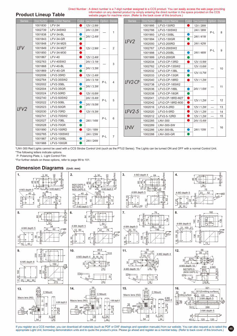
46
P.L
P.L
P.L
P.L
—
—
—
6
7
5
4
3
1
2
P.L
P.L
—
—
—
—
—
—
—
8
9
10
11
12
14
15
13
1612V / 18W
24V / 24W
24V / 23W
24V / 14W
12V / 9.3W
12V / 2.9W
12V / 6.6W
24V / 9.0W
24V / 8.4W
24V / 2.4W
24V / 2.2W
12V / 2.4W
12V / 2.9W
12V / 2.4W
24V / 3.3W
24V / 3.1W
24V / 3.3W
24V / 3.1W
24V / 10W
24V / 5.4W
12V / 1.2W
12V / 1.2W
12V / 1.2W
12V / 28W
12V / 1.2W
24V / 1.6W
12V / 1.2W
24V / 41W
24V / 38W
24V / 42W
12V / 0.9W
24V / 46W
12V / 0.7W
12V / 0.6W
Product Lineup Table
Model NameDirect NumberSeries Power Consumption OptionColor Dimension Model NameDirect NumberSeries Power Consumption OptionColor Dimension
*LNV-300 Red Lights cannot be used with a CCS Strobe Control Unit (such as the PTU2 Series). The Lights can be turned ON and OFF with a normal Control Unit.
Direct Number : A direct number is a 7-digit number assigned to a CCS product. You can easily access the web page providing information on any desired product by simply entering the direct number in the space provided on the CCS website pages for machine vision. (Refer to the back cover of this brochure.)
34(E
mitt
ing
surfa
ce)
46
40
20
713
40
41
1846
28
3 30
40
(1)
6
63 9(1
)
300
5 26
3
4-M3 depth 54-M3 depth 5
34(E
mitt
ing
surfa
ce)
46
40
20
713
40 41
46
3 30
40
(1)
M30.5XP0.5
2 Ø22
(1)
3
300
6
6
323
18 4-M3 depth 5
4-M3 depth 5
M27XP0.5M25.5XP0.5
34(E
mitt
ing
surfa
ce)
34(E
mitt
ing
surfa
ce)
40(E
mitt
ing
surfa
ce)
40(E
mitt
ing
surfa
ce)
36
60
32
64
62
40
38
40
36
15
(1)1
1
63
(1)
30010
12
1316
10
12
10
4-M3 depth 4
4-M4 depth 5
20
1.6
160
25 90 90
202
(Em
ittin
g su
rface
)
208
111 161
272
160
150
300
218
(Em
ittin
g su
rface
)
230
6-M5 depth 8
79 73
(Em
ittin
g su
rface
)
76(E
mitt
ing
surfa
ce)
84
115
50
12 60 42 78
120
50
504-M4 depth 5
300
300
7540
28
26
38(E
mitt
ing
surfa
ce)
46
23 5234
(Em
ittin
g su
rface
)
17
20
8 30
4-M3 depth 5
111
32
10 40
52(E
mitt
ing
surfa
ce)
58
32 6294
32
36
60
52(E
mitt
ing
surfa
ce)
300
4-M4 depth 5 21 100 21
130
(Em
ittin
g su
rface
)
136
100
142
182
73
136
20
100
16
1
100134
(Em
ittin
g su
rface
)
300
4-M4 depth 6
39 17
56
30
24
24
7 15 17
18
Ø34
60¡
18
18
300
15
4-M3 depth 10
4-M2 depth 4
300
18
54
16
16
5 24
34
24
34
26
15
Ø19
Ø29
39
83
21
108
C Mount
Macro lens (f40) 4-M4 depth 6300
18
83
188
54
16
16
5 24
34
24
34
26
15
Ø19
Ø29
39
C MountMacro lens (f32)
4-M4 depth 6
14
14
14
6 16 14
36 10.6
46.6
412
20
20
4-M3 depth 4
300
39 1756
30 24
7
60¡
18
300
15
Ø22Ø40
18 8
24
83(2
)
4-M3 depth 10
M27XP0.5
(M30.5XP0.5)
2-M3
20 70
116
70
100
(Em
ittin
g su
rface
)
106
102
(Em
ittin
g su
rface
)
110
148
104
76
76
56 92
300
4-M4 depth 5
1. 2. 3.
16.
9.
6.
4.
5. 7. 8.
11.
14. 15.
10. 12.
13.
300
18
54
16
16
5 24
34
24
34
26
15
Ø19
Ø29
39
83
71
158
C Mount
Macro lens (f40)
4-M4 depth 6
L
16.5 288
32
120 120
16
301(Emitting surface)
120 120
54
321
40.5
10
40.5
14
27
14
20(Emitting surface)
300
34
3-M4 depth 5
3-M4 depth 5
L
Dimension Diagrams (Unit: mm)
LFV
LFV2
1001830
1002739
1001838
1001843
1001848
1001849
1001850
1001867
1002763
1001868
1001869
1002006
1002764
1002002
1002004
1002024
1002740
1002022
1002023
1002030
1002741
1002027
1002028
1001990
1002765
1001987
1001988
LFV-34
LFV-34SW2
LFV-34-BL
LFV-34-GR
LFV-34-M25
LFV-34-M27
LFV-34-M30
LFV-40
LFV-40SW2
LFV-40-BL
LFV-40-GR
LFV2-35RD
LFV2-35SW2
LFV2-35BL
LFV2-35GR
LFV2-50RD
LFV2-50SW2
LFV2-50BL
LFV2-50GR
LFV2-70RD
LFV2-70SW2
LFV2-70BL
LFV2-70GR
LFV2-100RD
LFV2-100SW2
LFV2-100BL
LFV2-100GR
LFV2
LFV2!CP
LFV2!5
LNV
1001995
1002766
1001993
1001994
1002000
1002767
1001998
1001999
1002034
1002762
1002032
1002033
1002040
1002738
1002036
1002038
1002041
1002042
1002016
1002020
1002012
1002285
1002289
1002286
1002288
LFV2-130RD
LFV2-130SW2
LFV2-130BL
LFV2-130GR
LFV2-200RD
LFV2-200SW2
LFV2-200BL
LFV2-200GR
LFV2-CP-13RD
LFV2-CP-13SW2
LFV2-CP-13BL
LFV2-CP-13GR
LFV2-CP-18RD
LFV2-CP-18SW2
LFV2-CP-18BL
LFV2-CP-18GR
LFV2-CP-18RD-M27
LFV2-CP-18RD-M30
LFV2-5-2RD
LFV2-5-5RD
LFV2-5-12RD
LNV-300
LNV-300-SW
LNV-300-BL
LNV-300-GR
*The following letters indicate options.
P: Polarizing Plate, L: Light Control Film
*For further details on these options, refer to page 99 to 101.
If you register as a CCS member, you can download all materials (such as PDF or DXF drawings and operation manuals) from our website. You can also request us to select the appropriate Light Unit, borrowing demonstration units and to quote the product’s price. Please go ahead and register as a member today. (Refer to back cover of this brochure.)

Space-saving Design
Enables short-distance irradiation
Camera
LNSP-series Light Unit
High-output Line Light Unit with Reduced DiffusionLess diffusion means less loss of light quantity for long distance irradiation.
Line LightsLNSPseries
High-output LED Light Units for line sensors with natural air
cooling.
Compact for Short-distance IrradiationHigh Output of 400,000 lx
You can specify the length of the emitting surface you want in increments of 100 mm.
Select from sizes of 100 mm to 1,000 mm to meet your specific needs for a wide variety of applications.
Illumination structure of LNSP series Examples of Line Light Images
Liquid Crystal Glass, Batteries, Can Manufacturing, and More
47
These high-output line Light Units feature reduced light
diffusion. Less diffusion means less loss of light for
long-distance irradiation.
The compact design of the Light Unit allows for installation at a
narrow angle with the camera.
Order any Emitting Surface Length between 100 and 1,000 mm
Illuminance Graph
LWD (mm)
Illum
ina
tion
(lx)
0
50,000
100,000
150,000
200,000
250,000
300,000
350,000
400,000
450,000
50 100 150 200
* Measured value at 100% light intensity and an LWD of 50 mm. Results for individual Units may vary.
You can specify lengths in 100-mm increments between 100 mm...
...and 1,000 mm.
Inspecting liquid crystal glass for imperfections Visual inspection of cans Inspecting metal sheets for imperfections
Object
Camera
This model
Table rotation
Can rotation
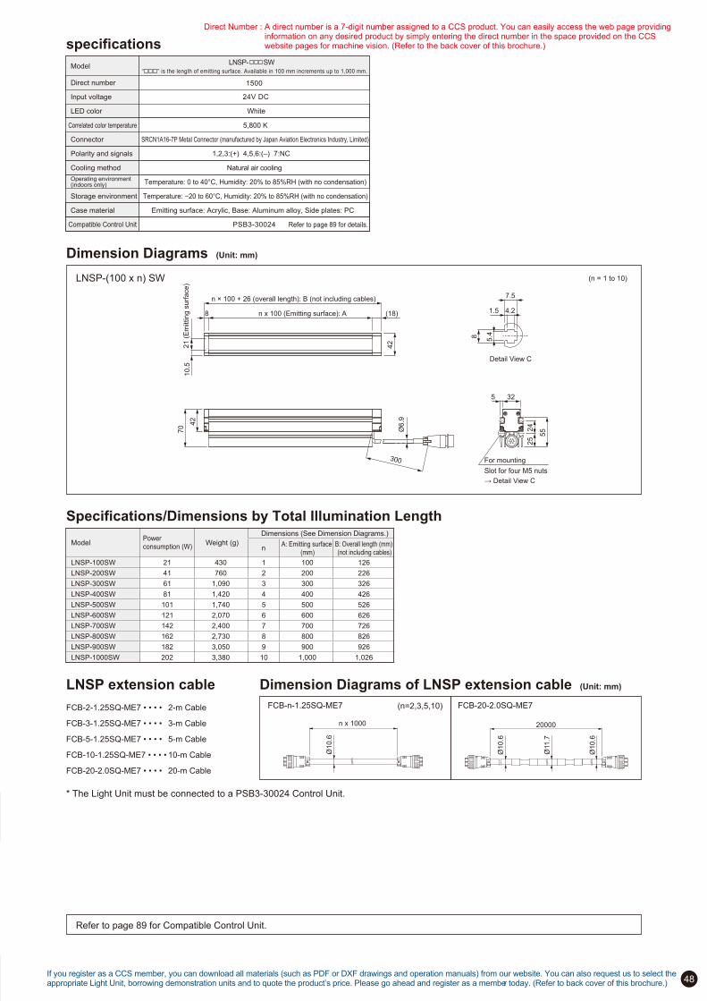
48
specificationsLNSP- SW
Model
Direct number
Refer to page 89 for Compatible Control Unit.
24V DC
1500
White
Input voltage
LED color
5,800 K Correlated color temperature
SRCN1A16-7P Metal Connector (manufactured by Japan Aviation Electronics Industry, Limited)
1,2,3:(+) 4,5,6:(–) 7:NC
Natural air cooling
Temperature: 0 to 40°C, Humidity: 20% to 85%RH (with no condensation)
Temperature: !20 to 60°C, Humidity: 20% to 85%RH (with no condensation)
Emitting surface: Acrylic, Base: Aluminum alloy, Side plates: PC
Connector
Polarity and signals
Cooling method
Operating environment (indoors only)
Storage environment
PSB3-30024 Compatible Control Unit
Case material
Refer to page 89 for details.
Dimension Diagrams (Unit: mm)
LNSP-(100 x n) SW (n = 1 to 10)
Specifications/Dimensions by Total Illumination Length
Dimension Diagrams of LNSP extension cable (Unit: mm)
FCB-20-2.0SQ-ME7 FCB-n-1.25SQ-ME7 (n=2,3,5,10)
n x 1000
Ø10.6
20000
Ø10.6
Ø11.7
Ø10.6
LNSP extension cable
FCB-2-1.25SQ-ME7 • • • •
FCB-3-1.25SQ-ME7 • • • •
FCB-5-1.25SQ-ME7 • • • •
FCB-10-1.25SQ-ME7 • • • •
FCB-20-2.0SQ-ME7 • • • •
2-m Cable
3-m Cable
5-m Cable
10-m Cable
20-m Cable
Ø6
.9
300
42
70
For mounting
5 32
24
2
5 5
5
Slot for four M5 nuts
" Detail View C
n x 100 (Emitting surface): A
21
(E
mittin
g s
urf
ace
)
42
8
n ! 100 + 26 (overall length): B (not including cables)
10
.5
(18)
5.4
8
1.5 4.2
7.5
Detail View C
Model Power consumption (W)
Weight (g)
Dimensions (See Dimension Diagrams.)
n A: Emitting surface
(mm)B: Overall length (mm) (not including cables)
LNSP-100SW
LNSP-200SW
LNSP-300SW
LNSP-400SW
LNSP-500SW
LNSP-600SW
LNSP-700SW
LNSP-800SW
LNSP-900SW
LNSP-1000SW
21
41
61
81
101
121
142
162
182
202
430
760
1,090
1,420
1,740
2,070
2,400
2,730
3,050
3,380
1
2
3
4
5
6
7
8
9
10
100
200
300
400
500
600
700
800
900
1,000
126
226
326
426
526
626
726
826
926
1,026
* The Light Unit must be connected to a PSB3-30024 Control Unit.
If you register as a CCS member, you can download all materials (such as PDF or DXF drawings and operation manuals) from our website. You can also request us to select the appropriate Light Unit, borrowing demonstration units and to quote the product’s price. Please go ahead and register as a member today. (Refer to back cover of this brochure.)
“ ” is the length of emitting surface. Available in 100 mm increments up to 1,000 mm.
Direct Number : A direct number is a 7-digit number assigned to a CCS product. You can easily access the web page providing information on any desired product by simply entering the direct number in the space provided on the CCS website pages for machine vision. (Refer to the back cover of this brochure.)
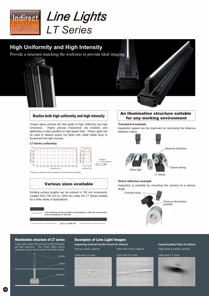
High Uniformity and High IntensityProvide a structure matching the worksites to provide ideal imaging.
Line LightsLT Series
Unique optics achieve the twin goals of high uniformity and high
luminance. Highly precise inspections are enabled, and
application is also possible on high-speed lines. These Lights can
be used to replace quartz rod lights with metal halide lamp or
fluorescent line light sources.
An illumination structure suitable
for any working environmentRealize both high uniformity and high intensity
Various sizes available
Emitting surface lengths can be ordered in 100 mm increments.
Lengths from 100 mm to 1,800 mm make the LT Series suitable
for a wide variety of applications.
Illumination structure of LT series
Object
Examples of Line Light Images
Inspecting Colored Acrylic Panels for Defects Inspecting Metal Plates for Defects
49
Unique optics achieve the twin goals of high uniformity
and high luminance. They enable highly precise
inspections, and can also be used for fast shutter speeds. Sink marks clearly captured
Light used: LT series
Slight dents accurately captured
Light used: LT series
Fish-eye clearly captured
Light used: LT series
Transparent example
LT Series uniformity
Direct reflection example
Compact setup
Close-up illumination possible
Other light
LT Series
Reduced deflection
Space saving
* Data is for reference only and does not ensure product quality.
Widthwise (mm)
Re
lative
ra
dia
nce
(%
)
0
20
40
60
80
100
0.2 1.1 1.9 2.80
20
40
60
80
100
Lengthwise (mm)
Re
lative
ra
dia
nce
(%
)
30025020015010050 350 400 500450 550 600
Widthwise
Lengthwise
The emitting surface length is selectable in 100 mm increments
from a minimum of 100 mm.
up to a 1,800 mm
Camera
This model
Inspection speed can be improved by narrowing the distance
between rollers.
Inspection is possible by mounting the camera at a narrow
angle.
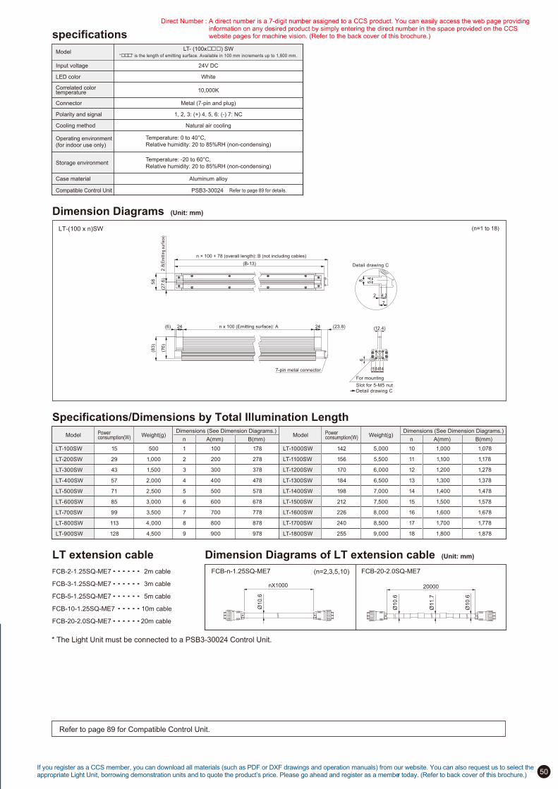
50
Specifications/Dimensions by Total Illumination Length
15 1
29 2
43 3
57 4
71 5
85 6
99 7
113 8
128
500
1,000
1,500
2,000
2,500
3,000
3,500
4,000
4,500 9
178
278
378
478
578
678
778
878
978
100
200
300
400
500
600
700
800
900
LT-1000SW 142 10
LT-1100SW 156 11
LT-1200SW 170 12
LT-1300SW 184 13
LT-1400SW 198 14
LT-1500SW 212 15
LT-1600SW 226 16
LT-1700SW 240 17
LT-1800SW 255
5,000
5,500
6,000
6,500
7,000
7,500
8,000
8,500
9,000 18
1,078
1,178
1,278
1,378
1,478
1,578
1,678
1,778
1,878
1,000
1,100
1,200
1,300
1,400
1,500
1,600
1,700
1,800
LT-100SW
LT-200SW
LT-300SW
LT-400SW
LT-500SW
LT-600SW
LT-700SW
LT-800SW
LT-900SW
Model Power consumption(W) Weight(g)
Dimensions (See Dimension Diagrams.)
n A(mm) B(mm)Model Power
consumption(W) Weight(g)Dimensions (See Dimension Diagrams.)
n A(mm) B(mm)
FCB-2-1.25SQ-ME7 2m cable
FCB-3-1.25SQ-ME7 3m cable
FCB-5-1.25SQ-ME7 5m cable
FCB-10-1.25SQ-ME7 10m cable
FCB-20-2.0SQ-ME7 20m cable
Dimension Diagrams of LT extension cable (Unit: mm)LT extension cable
FCB-20-2.0SQ-ME7FCB-n-1.25SQ-ME7 (n=2,3,5,10)
nX1000
Ø
10.6
20000
Ø10.6
Ø11.7
Ø10.6
If you register as a CCS member, you can download all materials (such as PDF or DXF drawings and operation manuals) from our website. You can also request us to select the appropriate Light Unit, borrowing demonstration units and to quote the product’s price. Please go ahead and register as a member today. (Refer to back cover of this brochure.)
Dimension Diagrams (Unit: mm)
LT-(100 x n)SW (n=1 to 18)
(B-13)
(27.
6)
2.8
(Em
ittin
g su
rfac
e)
58
n ! 100 + 78 (overall length): B (not including cables)
(6) n x 100 (Emitting surface): A24
(76
)
(23.8)24
(83
)
7-pin metal connector
Detail drawing C
8 5.4
2 4.2
7
(15)1414
6
(12.4)
For mounting
Slot for 5-M5 nut
Detail drawing C
Refer to page 89 for Compatible Control Unit.
* The Light Unit must be connected to a PSB3-30024 Control Unit.
specifications
Model
Input voltage
LED color
Correlated colortemperature
Connector
Polarity and signal
Cooling method
Operating environment(for indoor use only)
Storage environment
Case material
24V DC
White
10,000K
Metal (7-pin and plug)
1, 2, 3: (+) 4, 5, 6: (-) 7: NC
Natural air cooling
Temperature: 0 to 40°C,
Relative humidity: 20 to 85%RH (non-condensing)
Temperature: -20 to 60°C,
Relative humidity: 20 to 85%RH (non-condensing)
Aluminum alloy
PSB3-30024Compatible Control Unit Refer to page 89 for details.
“ ” is the length of emitting surface. Available in 100 mm increments up to 1,800 mm.
LT- (100x ) SW
Direct Number : A direct number is a 7-digit number assigned to a CCS product. You can easily access the web page providing information on any desired product by simply entering the direct number in the space provided on the CCS website pages for machine vision. (Refer to the back cover of this brochure.)
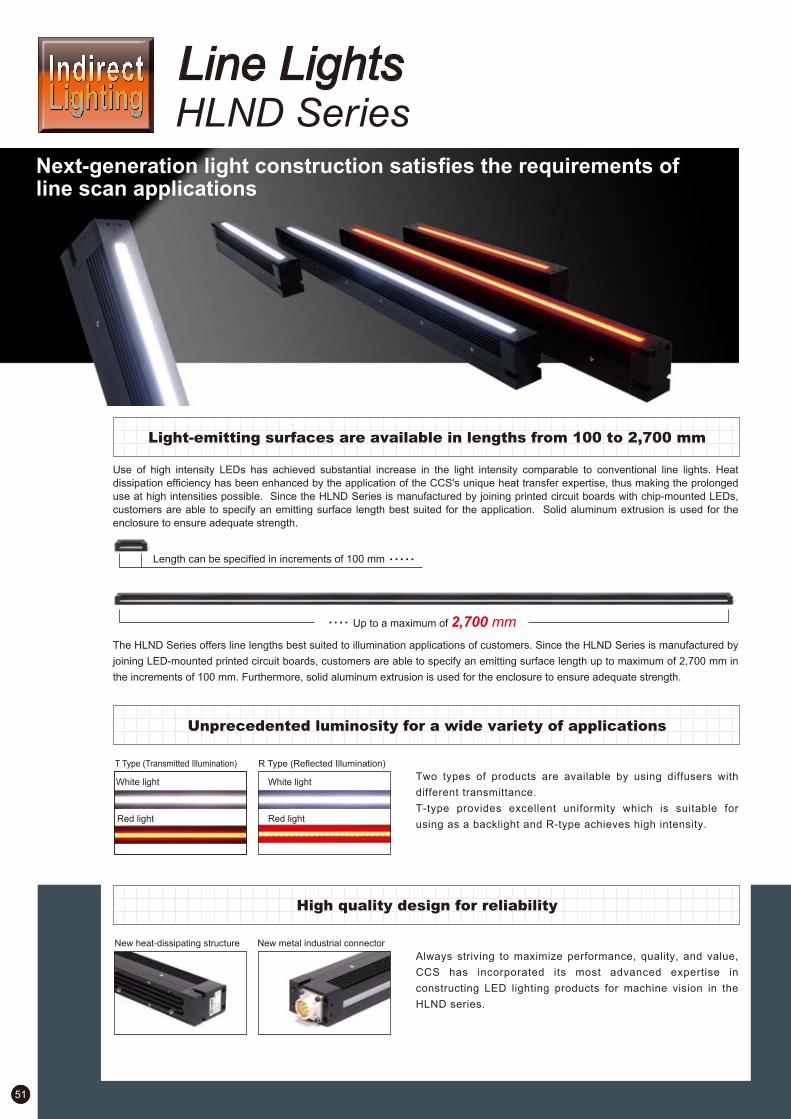
51
HLND SeriesNext-generation light construction satisfies the requirements of line scan applications
Line Lights
Length can be specified in increments of 100 mm
Use of high intensity LEDs has achieved substantial increase in the light intensity comparable to conventional line lights. Heat
dissipation efficiency has been enhanced by the application of the CCS's unique heat transfer expertise, thus making the prolonged
use at high intensities possible. Since the HLND Series is manufactured by joining printed circuit boards with chip-mounted LEDs,
customers are able to specify an emitting surface length best suited for the application. Solid aluminum extrusion is used for the
enclosure to ensure adequate strength.
The HLND Series offers line lengths best suited to illumination applications of customers. Since the HLND Series is manufactured by
joining LED-mounted printed circuit boards, customers are able to specify an emitting surface length up to maximum of 2,700 mm in
the increments of 100 mm. Furthermore, solid aluminum extrusion is used for the enclosure to ensure adequate strength.
Up to a maximum of 2,700 mm
New heat-dissipating structure New metal industrial connector
Always striving to maximize performance, quality, and value,
CCS has incorporated its most advanced expertise in
constructing LED lighting products for machine vision in the
HLND series.
Light-emitting surfaces are available in lengths from 100 to 2,700 mm
High quality design for reliability
T Type (Transmitted Illumination)
Unprecedented luminosity for a wide variety of applications
Two types of products are available by using diffusers with
different transmittance.
T-type provides excellent uniformity which is suitable for
using as a backlight and R-type achieves high intensity.
R Type (Reflected Illumination)
White light
Red light
White light
Red light
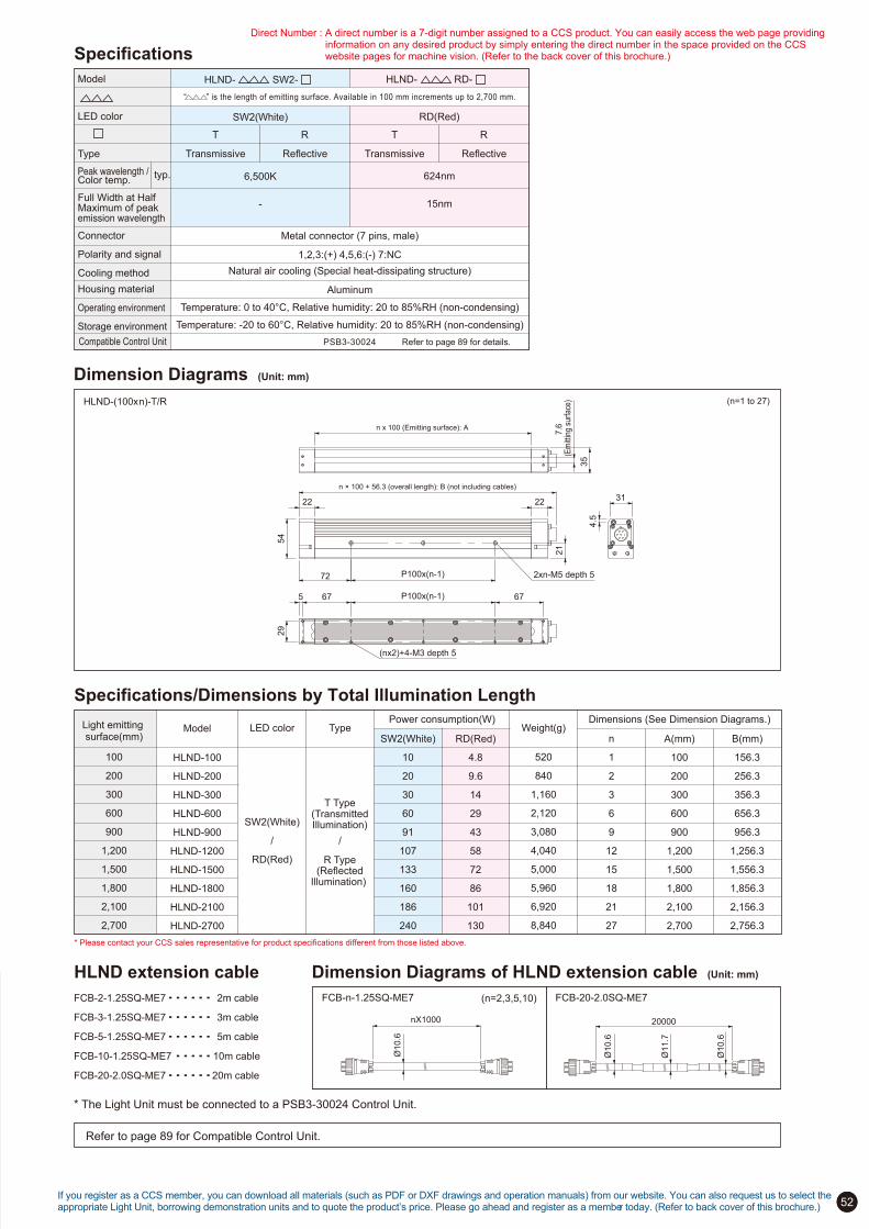
52If you register as a CCS member, you can download all materials (such as PDF or DXF drawings and operation manuals) from our website. You can also request us to select the appropriate Light Unit, borrowing demonstration units and to quote the product’s price. Please go ahead and register as a member today. (Refer to back cover of this brochure.)
Dimension Diagrams (Unit: mm)
HLND-(100xn)-T/R (n=1 to 27)
Refer to page 89 for Compatible Control Unit.
* The Light Unit must be connected to a PSB3-30024 Control Unit.
PSB3-30024 Refer to page 89 for details.
Model
HLND-100
HLND-200
HLND-300
HLND-600
HLND-900
HLND-1200
HLND-1500
HLND-1800
HLND-2100
HLND-2700
Light emitting surface(mm)
100
200
300
600
900
1,200
1,500
1,800
2,100
2,700
Weight(g)
520
840
1,160
2,120
3,080
4,040
5,000
5,960
6,920
8,840
LED color
SW2(White)
/
RD(Red)
Type
/
SW2(White)
10
20
30
60
91
107
133
160
186
240
RD(Red)
4.8
9.6
14
29
43
58
72
86
101
130
n
1
2
3
6
9
12
15
18
21
27
B(mm)
156.3
256.3
356.3
656.3
956.3
1,256.3
1,556.3
1,856.3
2,156.3
2,756.3
A(mm)
100
200
300
600
900
1,200
1,500
1,800
2,100
2,700
Dimensions (See Dimension Diagrams.)Power consumption(W)
Specifications/Dimensions by Total Illumination Length
T Type(TransmittedIllumination)
R Type(Reflected
Illumination)
* Please contact your CCS sales representative for product specifications different from those listed above.
FCB-2-1.25SQ-ME7 2m cable
FCB-3-1.25SQ-ME7 3m cable
FCB-5-1.25SQ-ME7 5m cable
FCB-10-1.25SQ-ME7 10m cable
FCB-20-2.0SQ-ME7 20m cable
Dimension Diagrams of HLND extension cable (Unit: mm)HLND extension cable
FCB-20-2.0SQ-ME7FCB-n-1.25SQ-ME7 (n=2,3,5,10)
nX1000
Ø
10.6
20000
Ø10.6
Ø11.7
Ø10.6
2xn-M5 depth 5
n ! 100 + 56.3 (overall length): B (not including cables)
n x 100 (Emitting surface): A
72
22
54
P100x(n-1)35
7.6
(E
mitt
ing
surf
ace)
5 67 67
29
P100x(n-1)
(nx2)+4-M3 depth 5
21
2231
4.5
HLND- SW2-
SW2(White)
6,500K
-
HLND- RD-
RD(Red)
624nm
15nm
Specifications
Transmissive Reflective Transmissive Reflective
Model
LED color
Type
Peak wavelength / Color temp.
Full Width at Half Maximum of peak emission wavelength
Connector
Polarity and signal
Cooling method
Housing material
Operating environment
Storage environment
typ.
“ ” is the length of emitting surface. Available in 100 mm increments up to 2,700 mm.
Compatible Control Unit
Metal connector (7 pins, male)
1,2,3:(+) 4,5,6:(-) 7:NC
Natural air cooling (Special heat-dissipating structure)
Aluminum
Temperature: 0 to 40°C, Relative humidity: 20 to 85%RH (non-condensing)
Temperature: -20 to 60°C, Relative humidity: 20 to 85%RH (non-condensing)
Direct Number : A direct number is a 7-digit number assigned to a CCS product. You can easily access the web page providing information on any desired product by simply entering the direct number in the space provided on the CCS website pages for machine vision. (Refer to the back cover of this brochure.)
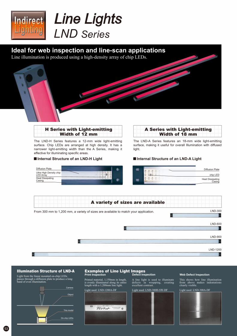
53
Camera
H Series with Light-emittingWidth of 12 mm
A Series with Light-emittingWidth of 18 mm
The LND-H Series features a 12-mm wide light-emitting
surface. Chip LEDs are arranged at high density. It has a
narrower light-emitting width than the A Series, making it
effective for illuminating specific areas.
The LND-A Series features an 18-mm wide light-emitting
surface, making it useful for overall Illumination with diffused
light.
A variety of sizes are available
From 300 mm to 1,200 mm, a variety of sizes are available to match your application.
Illumination Structure of LND-A Examples of Line Light ImagesLight from the linear mounted on-chip LEDs passes through a diffusion plate to produce a long band of even illumination.
Printed material, 1,150mm in length,is evenly illuminated along its entirelength with a 1,200mm line light.
Light used: LND-1200A-DF
A line light is used to illuminatedefects in wrapping, creatingexcellent contrast.
Light used: LND-300H-SW-DF
This shows how line illuminationfrom above makes indentationsclearly visible.
Light used: LND-300A-DF
Defect InspectionPrint Inspection Web Defect Inspection
Line LightsLND Series
Ideal for web inspection and line-scan applicationsLine illumination is produced using a high-density array of chip LEDs.
Diffusion Plate Diffusion Plate
chip LEDUltra High Density chip LED Array
Heat Dissipating Casing
Heat DissipatingCasing
Internal Structure of an LND-H Light Internal Structure of an LND-A Light

54
—
—
—
—
2
3
4
1
—
—
—
—
6
7
8
5
24V / 7.2W
24V / 14W
24V / 10W
24V / 22W
24V / 22W
24V / 40W
24V / 28W
24V / 30W
24V / 7.2W
24V / 14W
24V / 27W
24V / 22W
24V / 29W
24V / 40W
24V / 13W
Product Lineup Table
Model NameDirect NumberSeries Power Consumption OptionColor Dimension Model NameDirect NumberSeries Power Consumption OptionColor Dimension
* LND-series Red Lights cannot be used with a CCS Strobe Control Unit (such as the PTU2 Series). The Lights can be turned ON and OFF with a normal Control Unit.
* When the light-level is high and the light is left continually on, we recommend air-cooling the device by blowing air through the M5 hole.
LND!A
1002161
1002164
1002160
1002163
1002189
1002192
1003388
1002212
1002214
1002211
1002213
1002135
1002138
1002592
1002136
LND-300A-DF
LND-300A-SW-DF
LND-300A-BL-DF
LND-300A-GR-DF
LND-600A-DF
LND-600A-SW-DF
LND-600A-GR-DF
LND-900A-DF
LND-900A-SW-DF
LND-900A-BL-DF
LND-900A-GR-DF
LND-1200A-DF
LND-1200A-SW-DF
LND-1200A-BL-DF
LND-1200A-GR-DF
LND!H
1002167
1002171
1002166
1002170
1002194
1002198
1002193
1002197
1002215
1002219
1002670
1002217
1002139
LND-300H-DF
LND-300H-SW-DF
LND-300H-BL-DF
LND-300H-GR-DF
LND-600H-DF
LND-600H-SW-DF
LND-600H-BL-DF
LND-600H-GR-DF
LND-900H-DF
LND-900H-SW-DF
LND-900H-BL-DF
LND-900H-GR-DF
LND-1200H-DF
If you register as a CCS member, you can download all materials (such as PDF or DXF drawings and operation manuals) from our website. You can also request us to select the appropriate Light Unit, borrowing demonstration units and to quote the product’s price. Please go ahead and register as a member today. (Refer to back cover of this brochure.)
depth 4.5 depth 4.5 depth 4.5 depth 4.5
depth 4.5depth 4.5depth 4.5depth 4.5
1. 2. 3.
6.
4.
5. 7. 8.
Dimension Diagrams (Unit: mm)
300
300
300
300
300
300
300
300
Direct Number : A direct number is a 7-digit number assigned to a CCS product. You can easily access the web page providing information on any desired product by simply entering the direct number in the space provided on the CCS website pages for machine vision. (Refer to the back cover of this brochure.)
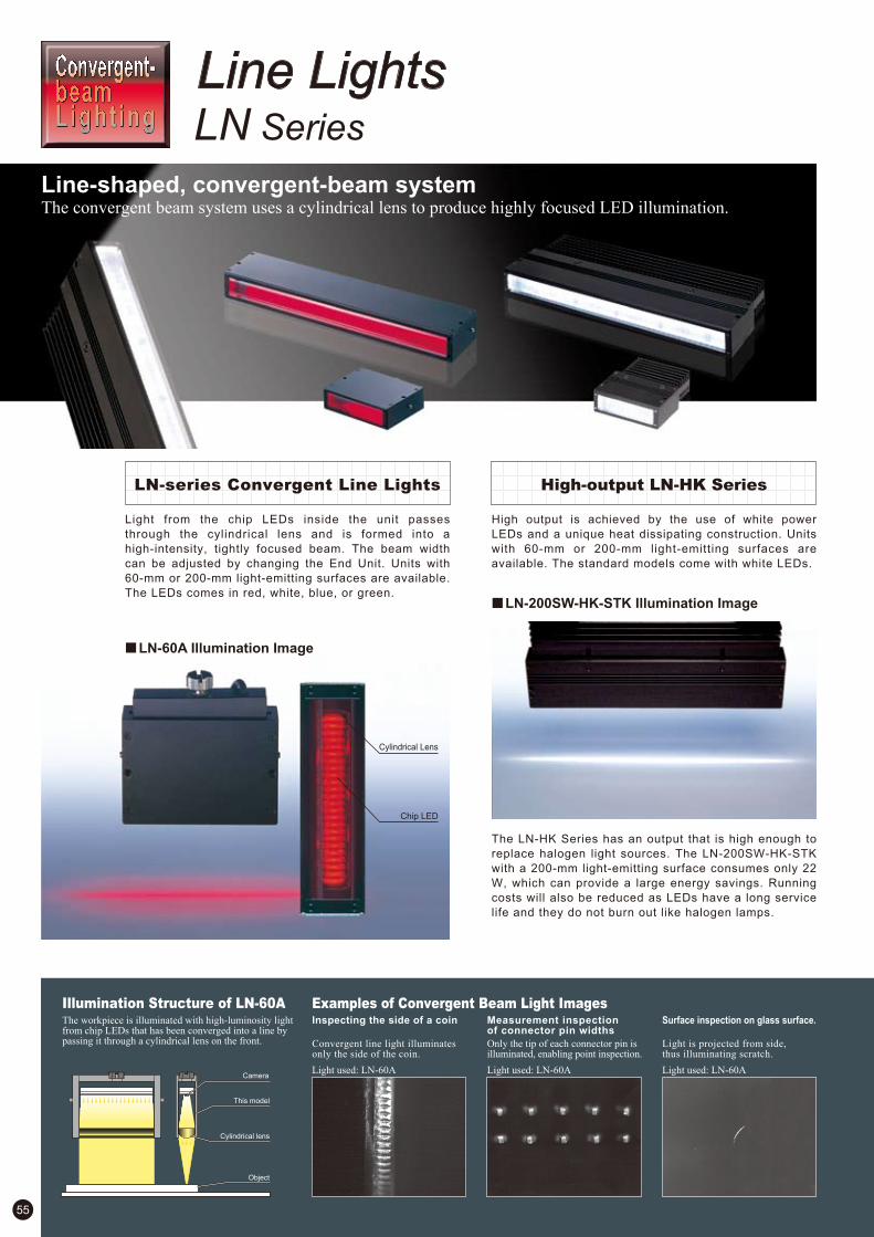
55
Camera
LN Series
Line-shaped, convergent-beam systemThe convergent beam system uses a cylindrical lens to produce highly focused LED illumination.
Line Lights
Illumination Structure of LN-60AThe workpiece is illuminated with high-luminosity light from chip LEDs that has been converged into a line by passing it through a cylindrical lens on the front.
Examples of Convergent Beam Light Images
Convergent line light illuminates only the side of the coin.
Light used: LN-60A
Only the tip of each connector pin is illuminated, enabling point inspection.
Light used: LN-60A
Light is projected from side, thus illuminating scratch.
Light used: LN-60A
Inspecting the side of a coin Measurement inspection of connector pin widths
Surface inspection on glass surface.
Light from the chip LEDs inside the unit passes
through the cylindrical lens and is formed into a
high-intensity, tightly focused beam. The beam width
can be adjusted by changing the End Unit. Units with
60-mm or 200-mm light-emitting surfaces are available.
The LEDs comes in red, white, blue, or green.
LN-series Convergent Line Lights High-output LN-HK Series
High output is achieved by the use of white power
LEDs and a unique heat dissipating construction. Units
with 60-mm or 200-mm light-emitting surfaces are
available. The standard models come with white LEDs.
The LN-HK Series has an output that is high enough to
replace halogen light sources. The LN-200SW-HK-STK
with a 200-mm light-emitting surface consumes only 22
W, which can provide a large energy savings. Running
costs will also be reduced as LEDs have a long service
life and they do not burn out like halogen lamps.
Cylindrical Lens
Chip LED
LN-60A Illumination Image
LN-200SW-HK-STK Illumination Image
Object
This model
Cylindrical lens
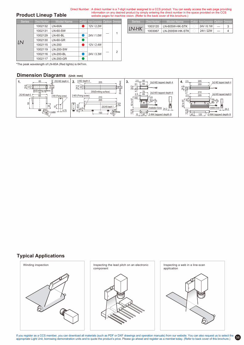
56
2X2-M3 depth 7
200(Emitting surface)
4-M2 depth 4
2-M3 (Fixing screw)2X2-M3 depth 6
60(Emitting surface)
2X2-M2 depth 4
2-M3 (Fixing screw)
—
—
2
1—
—
4
3
2x2-M3 tapped depth 6
2x2-M2 tapped depth 4
2-M4 tapped depth 8
2x2-M3 tapped depth 6
2x2-M2 tapped depth 4
Installation Screw Installation Screw
16
(Em
ittin
g su
rface
)
210
20
205
205
100 300
25
15
24.5
45.6
(8) 10
19.6
70
13.6
(Em
ittin
g su
rface
)
65
300
25
50
13
65
9.75
19
16
210
2.5 205
82 to 9
7
45.520
15
200
24.5
2.5 205
4.7
5
24.2
1204512.2
5
82 to 9
7
2.5 6570
45.520
2.5
6015
24.5
65
4.7
5
40 2-M4 tapped depth 812.2
5
15
24.2
1. 2. 3. 4.
300
30012V / 2.2W
24V / 3.3W
12V / 2.4W
24V / 1.0W
24V / 6.1W
24V / 22W
Product Lineup Table
Model NameDirect NumberSeries Power Consumption OptionColor Dimension Model NameDirect NumberSeries Power Consumption OptionColor Dimension
Dimension Diagrams (Unit: mm)
Typical Applications
Inspecting the lead pitch on an electronic
component
Winding inspection Inspecting a web in a line-scan
application
*The peak wavelength of LN-60A (Red lights) is 647nm.
If you register as a CCS member, you can download all materials (such as PDF or DXF drawings and operation manuals) from our website. You can also request us to select the appropriate Light Unit, borrowing demonstration units and to quote the product’s price. Please go ahead and register as a member today. (Refer to back cover of this brochure.)
Direct Number : A direct number is a 7-digit number assigned to a CCS product. You can easily access the web page providing information on any desired product by simply entering the direct number in the space provided on the CCS website pages for machine vision. (Refer to the back cover of this brochure.)
LN
1002132
1002131
1002129
1002130
1002115
1002119
1002116
1002117
LN-60A
LN-60-SW
LN-60-BL
LN-60-GR
LN-200
LN-200-SW
LN-200-BL
LN-200-GR
LN!HK1003120
1003067
LN-60SW-HK-STK
LN-200SW-HK-STK

57
Ideal for detecting scratches, indentations and dirt on a mirrored work surfaceThis Collimated-light optical unit is designed for use in inspecting reflective surfaces such as CDs and wafers for small flaws, dents, and dirt.
Coaxial LightsMSU/MFU Series
Light emitted from any normal light source propagates in a radial
fashion, and disperses as it gets further from the source. Light
from a distant source such as the sun (considered to be from an
infinite distance) strikes any surface uniformly. The rays are
parallel or collimated. The MSU-series Coaxial Light Units have
been developed using this principle.
Using light from a collimated light source is useful for detecting
shallow flaws and dents in flat, reflective objects, which were
previously difficult to detect. It is also ideal for reading bar
codes and laser-engraved characters.
The use of LED illumination
achieves the triple benefits
of high performance, high
stability, and low cost.
Proving the sophistication
of our technology, this
ground-braking product
opens up new fields of
application for LED lights.
The MSU Series enables clear
imaging of flaws on CD surfaces,
engraved characters on lead
frames, and 2D code, that were
previously difficult to detect using
normal coaxial light.
New technology:
Collimated-light optical unit
For small, glossy applications
(MSU-10)
Inspect for flaws, dents,
and dirt on reflective surfaces
Reading two-dimensional code
Sunlight Light from a light bulb
MSU-10 Features
The camera can be mounted directly onto the C mount at the top of the unit.
Built-in macro lens allows the field of view to be adjusted from 5 to 15 mm.
The enclosed focusing adapter allows you to select the optimum light for the workpiece. (Select according to the surface condition and roughness of the workpiece; light intensity is adjustable.)
A lightweight and compact design enables installation in cramped locations.
Examples of Collimated Light Images
Flaws and nicks on the lens surface are imaged.
Light used: MSU-10
Inspecting for flaws on a lenssurface
The fine laser characters are clearlyimaged
Light used: MSU-10
Inspecting laser characters on a lead frame
Warped and depressed parts are clearly imaged as black cloudy areas.
Light used: MSU-10
Inspecting for warping and depressions in a CSP
Very finely engraved characters appear with clarity and good contrast.
Light used: MSU-10
Inspecting laser engraved characters on a water
Reference of F.O.V
MSU-10
MSU-30
MSU-30X20
MSU-100
7.5mm
18.7mm
15mm
60mm
58mm
50mm
24mm
50mm
Field of View WDModel name
Note:
The aboce reference is used as a guide when you
select a LED light. The actual data may differ under
different imaging conditions or other environment.
Camera used: 1/3 CCD camera
If you register as a CCS member, you can download all materials (such as PDF or DXF drawings and operation manuals) from our website. You can also request us to select the appropriate Light Unit, borrowing demonstration units and to quote the product’s price. Please go ahead and register as a member today. (Refer to back cover of this brochure.)
180
156
680
160
500
20259.2 4-Ø11
Dimension Diagrams (Unit: mm)
1. 3. 4.2.
5. 6. 7.467
211 256
481
180160
210
250
20 4-Ø11
46
90
3 40 3 15 60 15
38
10
28
34(E
mitt
ing
surfa
ce) 5 30(Emitting surface)
16
Ø20
300
2X2-M3
4-M3 depth 6
66
130
3 60 3 15 100 1510
38
48
5 40(Emitting surface)
54(E
mitt
ing
surfa
ce)
Ø20
16
300
2X2-M3
4-M3 depth 6
20
C mount
(1)
LV-27
300
300
(for installation)
4-M3 depth 6
(for installation)2x2-M3 depth 8
74
115
44
67
858
39
3 40
7
LW
D=
20 t
o 8
0m
m
LV-27
(for installation)
4-M627
C mount
CCTV Lens f50mm
Center of the optical axis 44
76 116
351
2370
80
70
(Provided on both sides)
(for installation)4-M3 depth 8
(for installation)
2x2-M3 depth 8
66
67
3 60
30
125
(1)
(126.5
)
54
7
C mount
49
65 152646
(Provided on both sides)
Model NameDirect NumberSeries Power Consumption OptionColor Dimension
—
—
7
612V / 0.3W
12V / 0.3WMFU1002460
1002462
MFU-34X30-BL
MFU-54X40-BL
Model NameDirect NumberSeries Power Consumption OptionColor Dimension
MSU
—
—
—
—
—
—
3
2
1
5
4
12V / 0.5W
24V / 0.8W
12V / 0.7W
24V / 0.8W
12V / 0.7W
24V / 0.8W
12V / 0.7W
12V / 0.7W
12V / 0.7W24V / 4.9W
1002469
1002471
1002470
1002476
1002477
1002479
1002485
1002481
1002483
1002472
1002473
1002474
MSU-10
1005549 MSU-10RD2
MSU-10-SW
MSU-10-BL
MSU-30
1005550 MSU-30RD2
MSU-30-BL
MSU-30X20
1005547 MSU-30X20RD2
MSU-30X20-SW
MSU-30X20-BL
MSU-30X20-GR
MSU-100
MSU-130
MSU-130-CL赤色照明RDは生産終了を予定しております。赤色照明のご選定に際しては、RD2をお求めください。また、RD製品の生産終了時期に関しては、Webサイトの生産終了品ページでご確認ください。RDとRD2では、入力電圧が違います。ご利用の際には供給する電源がDC24Vであることをご確認ください。RDとRD2との比較について詳しくはP.1をご参照ください。
300
Existing RD-type Red Lights will be discontinued at the April 15, 2013. RD2-type Red Lights is recommended as replacement. The RD-type and RD2-type Lights have different input voltages. Always use a 24-VDC Control Unit with RD2-type Lights. For a comparison between the RD-type and RD2-type Lights, refer to page 1.
Direct Number : A direct number is a 7-digit number assigned to a CCS product. You can easily access the web page providing information on any desired product by simply entering the direct number in the space provided on the CCS website pages for machine vision. (Refer to the back cover of this brochure.)
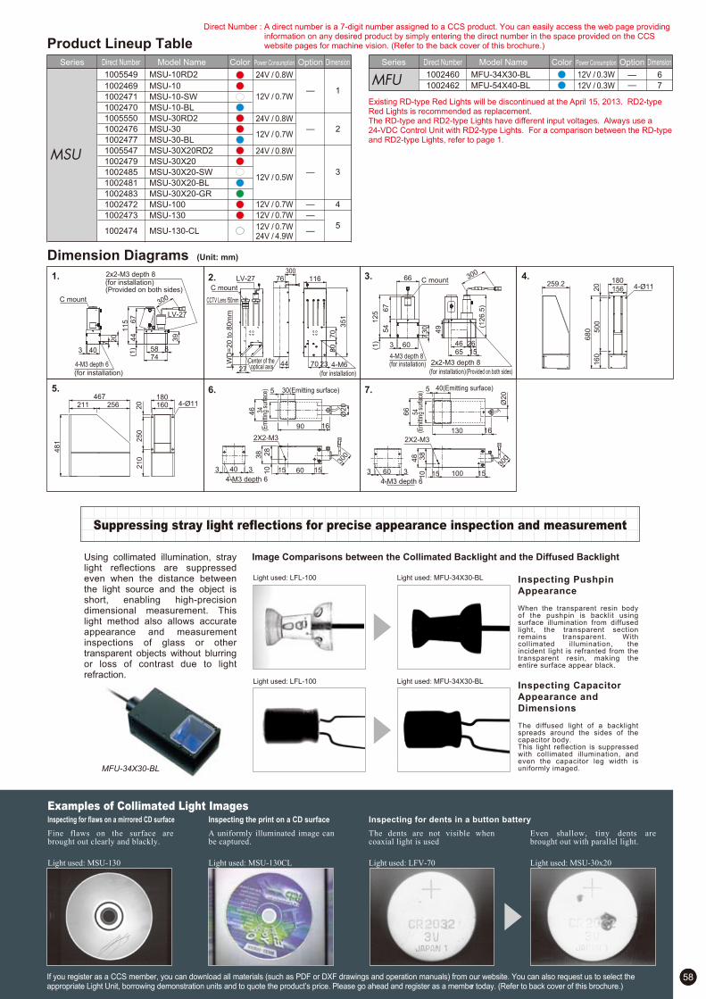
58
Product Lineup Table
Suppressing stray light reflections for precise appearance inspection and measurement
Light used: LFL-100 Light used: MFU-34X30-BL
Light used: LFL-100 Light used: MFU-34X30-BL
Using collimated illumination, stray light reflections are suppressed even when the distance between the light source and the object is short, enabling high-precision dimensional measurement. This light method also allows accurate appearance and measurement inspections of glass or other transparent objects without blurring or loss of contrast due to light refraction.
Inspecting Pushpin
Appearance
When the transparent resin body of the pushpin is backlit using surface illumination from diffused light, the transparent section remains transparent. With collimated illumination, the incident light is refranted from the transparent resin, making the entire surface appear black.
Inspecting Capacitor
Appearance and
Dimensions
The diffused light of a backlight spreads around the sides of the capacitor body.This light reflection is suppressed with collimated illumination, and even the capacitor leg width is uniformly imaged.MFU-34X30-BL
Image Comparisons between the Collimated Backlight and the Diffused Backlight
Inspecting for dents in a button batteryInspecting the print on a CD surface
The dents are not visible when coaxial light is used
Light used: LFV-70
Even shallow, tiny dents are brought out with parallel light.
Light used: MSU-30x20
Examples of Collimated Light ImagesInspecting for flaws on a mirrored CD surface
Fine flaws on the surface are brought out clearly and blackly.
Light used: MSU-130
A uniformly illuminated image can be captured.
Light used: MSU-130CL
If you register as a CCS member, you can download all materials (such as PDF or DXF drawings and operation manuals) from our website. You can also request us to select the appropriate Light Unit, borrowing demonstration units and to quote the product’s price. Please go ahead and register as a member today. (Refer to back cover of this brochure.)
180
156
680
160
500
20259.2 4-Ø11
Dimension Diagrams (Unit: mm)
1. 3. 4.2.
5. 6. 7.467
211 256
481
180160
210
250
20 4-Ø11
46
90
3 40 3 15 60 15
38
10
28
34(E
mitt
ing
surfa
ce) 5 30(Emitting surface)
16
Ø20
300
2X2-M3
4-M3 depth 6
66
130
3 60 3 15 100 1510
38
48
5 40(Emitting surface)
54(E
mitt
ing
surfa
ce)
Ø20
16
300
2X2-M3
4-M3 depth 6
20
C mount
(1)
LV-27
300
300
(for installation)
4-M3 depth 6
(for installation)2x2-M3 depth 8
74
115
44
67
858
39
3 40
7
LW
D=
20 t
o 8
0m
m
LV-27
(for installation)
4-M627
C mount
CCTV Lens f50mm
Center of the optical axis 44
76 116
351
2370
80
70
(Provided on both sides)
(for installation)4-M3 depth 8
(for installation)
2x2-M3 depth 8
66
67
3 60
30
125
(1)
(126.5
)
54
7
C mount
49
65 152646
(Provided on both sides)
Model NameDirect NumberSeries Power Consumption OptionColor Dimension
—
—
7
612V / 0.3W
12V / 0.3WMFU1002460
1002462
MFU-34X30-BL
MFU-54X40-BL
Model NameDirect NumberSeries Power Consumption OptionColor Dimension
MSU
—
—
—
—
—
—
3
2
1
5
4
12V / 0.5W
24V / 0.8W
12V / 0.7W
24V / 0.8W
12V / 0.7W
24V / 0.8W
12V / 0.7W
12V / 0.7W
12V / 0.7W24V / 4.9W
1002469
1002471
1002470
1002476
1002477
1002479
1002485
1002481
1002483
1002472
1002473
1002474
MSU-10
1005549 MSU-10RD2
MSU-10-SW
MSU-10-BL
MSU-30
1005550 MSU-30RD2
MSU-30-BL
MSU-30X20
1005547 MSU-30X20RD2
MSU-30X20-SW
MSU-30X20-BL
MSU-30X20-GR
MSU-100
MSU-130
MSU-130-CL
300
Existing RD-type Red Lights will be discontinued at the April 15, 2013. RD2-type Red Lights is recommended as replacement. The RD-type and RD2-type Lights have different input voltages. Always use a 24-VDC Control Unit with RD2-type Lights. For a comparison between the RD-type and RD2-type Lights, refer to page 1.
Direct Number : A direct number is a 7-digit number assigned to a CCS product. You can easily access the web page providing information on any desired product by simply entering the direct number in the space provided on the CCS website pages for machine vision. (Refer to the back cover of this brochure.)

59
—
—
—
—
—
—
—
—
—
—
—
—
—
—
—
—
—
—
—
—
—
—
—
—
—
—
—
—
—
—
—
1
2
1
3
4
5
6
7
8
8
9
10
11
12
13
14
15
16
17
18
19
20
21
Unprotected Anti-spark Protection
Unprotected UV Light Model vs. New Model with Anti-spark Protection
UV Series
Ultraviolet Lights
Spark-prevention structure achieves enhanced safety and reliabilityUse of an original UV light LED with a peak wavelength of 365mm and a directional pattern of 20 .
Many ultraviolet LEDs have packages made from iron alloy, making them
vulnerable to static electricity. This has created a major problem with individual
LED failure due to a spark occurring when there is contact with a piece of
conductive material. CCS's original ultraviolet LED has eliminated this problem
by employing a proprietary anti-spark protection feature.
While an LED usually has two leads,
CCS's original ultraviolet LED is provided
with an additional lead. This unique
structure has achieved a spark prevention
effect.
Employment of original ultraviolet LED achieving even higher safety and reliability
CCS's proprietary LED package with
anti-spark protection
Distribution of emission spectrum of UV light LED
Directional pattern of UV light LED
Ultraviolet transmission filter Ultraviolet cutting filter
Option filter
The original UV light LED is
available with a peak
wavelength of 365mm and a
directional pattern of ±20°
The use of a single
wavelength as a
characteristic of the LED
gives a more precise image
of the characteristics of a
workpiece compared with the
use of conventional black
lights, and allows for stable
shooting over an extended
period of time.
A wide product lineup offers
optimum lighting solutions
best suited to a variety of
inspection objects, inspection
environments and optical
systems.
Wavelength of 365 nm and LED light spread of ±20°
U340 Series
U340-25
U340-27
U340-30
U340-40
U340-46
M25.5 P0.5
M27.0 P0.5
M30.5 P0.5
M40.5 P0.5
M46.0 P0.75
Model Size
L42 Series
L42-25
L42-27
L42-30
L42-40
L42-46
M25.5 P0.5
M27.0 P0.5
M30.5 P0.5
M40.5 P0.5
M46.0 P0.75
Model Size
300 400 500 600 700 8000
20
100
80
60
40
Filter characteristic vs. UV LED emission spectrum distribution
Wavelength (nm)
Tra
nsm
issio
n (
%)
U340 filter
L42 filter
365 nm UV LED emission spectrum distribution
0
-20 -10 -30 +20 +10 +30 0
2020
4040
6060
8080
-90
-80
-70
-60
-50
-40
+90
+80
+70
+60
+50
+40
Rela
tive e
mis
sion in
tensi
ty (
%)
Radiation angle
450400350
Wavelength (nm)
3002500
20
100
80
60
40
Rela
tive e
mis
sio
n inte
nsity (
%)

60
—
—
—
—
—
—
—
—
—
—
—
—
—
—
—
—
—
—
—
—
—
—
—
—
—
—
—
—
—
—
—
1
2
1
3
4
5
6
7
8
8
9
10
11
12
13
14
15
16
17
18
19
20
21
24V / 0.4W
24V / 0.8W
24V / 1.2W
24V / 3.1W
24V / 3.8W
24V / 6.1W
24V / 9.5W
24V / 1.6W
24V / 1.9W
24V / 4.6W
24V / 6.9W
24V / 9.9W
24V / 12W
24V / 1.6W
24V / 2.3W
24V / 3.1W
24V / 3.8W
24V / 4.6W
24V / 0.4W
24V / 0.8W
24V / 3.1W
24V / 1.6W
24V / 2.3W
24V / 3.8W
24V / 1.6W
24V / 1.6W
24V / 3.1W
24V / 6.1W
24V / 9.1W
24V / 1.9W
24V / 1.2W
Product Lineup Table
Model NameDirect NumberSeries Power Consumption OptionColor Dimension Model NameDirect NumberSeries Power Consumption OptionColor Dimension
Dimension Diagrams (Unit: mm)
Direct Number : A direct number is a 7-digit number assigned to a CCS product. You can easily access the web page providing information on any desired product by simply entering the direct number in the space provided on the CCS website pages for machine vision. (Refer to the back cover of this brochure.)
1. 3.
4. 5. 6.
7. 8. 9.
10. 11. 12.
2.
13.
14. 15. 16. 17.
18. 19. 20. 21.
4-M3 depth 445
D
A B
C
300
22
Ø70
Ø35
4-M3 depth 5
300
P.C.D.50
45
Ø48
Ø74
19
300
454-M3 depth 5
P.C.D.60
4-M3 depth 4Ø30
300
56
38
56
38
18
Ø60
Ø120
31.5
4-M3 depth 5
300
P.C.D.90
45
4-M3 depth 5
DA B
C
30045
CBA
4-M3 depth 4 1245
300
Ø46
Ø75
Ø56
4-M3 depth 4
300
12
Ø55
34(Emitting surface)
8.4(Emitting surface)
2-M2 depth 5
2-M3 depth 4
5 5
10.444
815
20
5
1212
300
42(Emitting surface)
2X2-M2 depth 5
15(Emitting surface)
49
7
20
52
17
10
300
74(Emitting surface)27.2
(Emitting surface)
2-M3 depth 4
18
50
28.8
86
300
181.4(Emitting surface)
16(Emitting surface)
2X2-M2 depth 5
18
191.4
21
49
8
21
10
300
42
(Em
ittin
g su
rface
)
15(Emitting surface)
300
90
108
108 60
60
30.2
70
70
4-M4
3.2
2-M3(Fixing screw)
2X2-M3 depth 7
16
(Emi
tting s
urfac
e)
200(Emitting surface)4-M2 depth 4
210
20
205
205
100 300
25
15
24.5
45.6
(8)
10
2X2-M2 depth 5
15(Emitting surface)130(Emitting surface)
49
8
21
140
17
300
10
34(Emitting surface)
8.4
(Em
ittin
g su
rface
)
4-M3
78
78
17
46
42
36
36 4
2
44
10
5 5
300
130(Emitting surface)
8-M4 depth 4
15
(Em
ittin
g su
rface
)
90
200
200 1
50
150
31.2
100
175
3.2
100
300
82(Emitting surface)
2X2-M2 depth 5
15(Emitting surface)
92
17
10
20
49
300
7
4-M2.6 depth 3
58
58
25
12
25
30
30
30
30 3
00
82(Emitting surface)
15
(Em
ittin
g su
rface
)
90
148
148 1
00
100
30.2
110
110
4-M4
300
3.2
Ø41
Ø33
(Em
ittin
g su
rface
)
300
2-M4Fixing screw
(51.5)
40 (11.5)
8
2 36 2
26
12
A
Ø32
Ø42
Ø50
Ø90
Ø90
B
Ø10
Ø18
Ø28
Ø50
Ø30
C
16
18
16
20
20
D
P.C.D.20
P.C.D.28
P.C.D.40
P.C.D.70
P.C.D.70
LDR2-32UV365
LDR2-42UV365
LDR2-50UV365
LDR2-90UV365
LDR2-90-30UV365
Model Name
A
Ø100
Ø132
Ø170
Ø208
B
Ø70
Ø96
Ø134
Ø174
C
22
22
22
22
D
P.C.D.84
P.C.D.116
P.C.D.154
P.C.D.186
LDR2-100UV365-LA
LDR2-132UV365-LA
LDR2-170UV365-LA
LDR2-208UV365-LA
Model Name
A
Ø96
Ø146
Ø176
Ø206
B
Ø80
Ø130
Ø160
Ø190
C
Ø60
Ø110
Ø140
Ø170
LDR-96UV365-LA-1
LDR-146UV365-LA-1
LDR-176UV365-LA-1
LDR-206UV365-LA-1
Model Name
LDR2
LDR2!LA
LDR!LA!1
SQR
1002639
1002640
1002641
1002605
1002642
1002638
1002643
1002649
1002606
1002637
1002634
1002636
1002635
1002630
1002629
1002632
LDR2-32UV365
LDR2-42UV365
LDR2-50UV365
LDR2-70UV365
LDR2-90UV365
LDR2-90-30UV365
LDR2-120UV365
SQR-56UV365
LDR2-74UV365-LA
LDR2-100UV365-LA
LDR2-132UV365-LA
LDR2-170UV365-LA
LDR2-208UV365-LA
LDR-75UV365-LA-1
LDR-96UV365-LA-1
LDR-146UV365-LA-1
LDQ
LSPLN
LDL
1002633
1002631
1002648
1002604
1002603
1002602
1002647
1002628
1002644
1002645
1002608
1002607
1002646
1002650
1002651
LDR-176UV365-LA-1
LDR-206UV365-LA-1
LDL-34X8UV365
LDL-42X15UV365
LDL-74X27UV365
LDL-82X15UV365
LDL-130X15UV365
LDL-180X16UV365
LDQ-60-25UV365
LDQ-78UV365
LDQ-100UV365
LDQ-150UV365
LDQ-200UV365
LN-200UV365
LSP-41UV365
LDR!LA!1
If you register as a CCS member, you can download all materials (such as PDF or DXF drawings and operation manuals) from our website. You can also request us to select the appropriate Light Unit, borrowing demonstration units and to quote the product’s price. Please go ahead and register as a member today. (Refer to back cover of this brochure.)
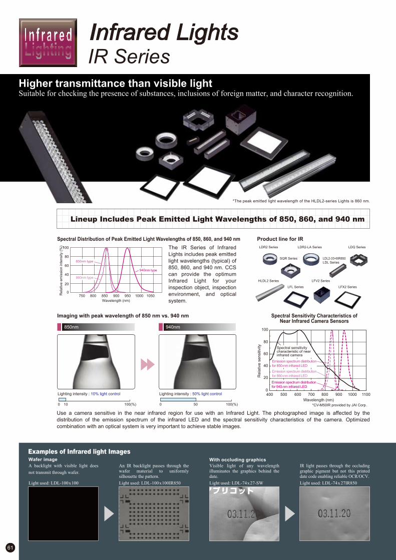
61
IR Series
Infrared Lights
Higher transmittance than visible lightSuitable for checking the presence of substances, inclusions of foreign matter, and character recognition.
Lineup Includes Peak Emitted Light Wavelengths of 850, 860, and 940 nm
The IR Series of Infrared
Lights includes peak emitted
light wavelengths (typical) of
850, 860, and 940 nm. CCS
can provide the optimum
Infrared Light for your
inspection object, inspection
environment, and optical
system.
Spectral Distribution of Peak Emitted Light Wavelengths of 850, 860, and 940 nm Product line for IR
Imaging with peak wavelength of 850 nm vs. 940 nm
850nm 940nm
Wavelength (nm)
Re
lative
em
issio
n in
ten
sity (
%)
Spectral Sensitivity Characteristics ofNear Infrared Camera Sensors
Use a camera sensitive in the near infrared region for use with an Infrared Light. The photographed image is affected by the
distribution of the emission spectrum of the infrared LED and the spectral sensitivity characteristics of the camera. Optimized
combination with an optical system is very important to achieve stable images.
Lighting intensity : 10% light control Lighting intensity : 50% light control
Re
lative
se
nsitiv
ity
Wavelength (nm)
Spectral sensitivity characteristic of near infrared camera
Emission spectrum distribution
for 850-nm infrared LED
Emission spectrum distribution
for 860-nm infrared LED
Emission spectrum distribution
for 940-nm infrared LED
*CV-M50IR provided by JAI Corp.
Examples of Infrared light ImagesWafer image With occluding graphics
A backlight with visible light does
not transmit through wafer.
Light used: LDL-100x100
An IR backlight passes through the
wafer material to uniformly
silhouette the pattern.
Light used: LDL-100x100IR850
Visible light of any wavelength
illuminates the graphics behind the
date.
Light used: LDL-74x27-SW
IR light passes through the occluding
graphic pigment but not this printed
date code enabling reliable OCR/OCV.
Light used: LDL-74x27IR850
9509008508007500
20
80
100
60
40
10501000
0 10 100(%) 0 50 100(%)
900 1000800700600500400 1100
80
100
60
40
20
0
LFX2 Series
LDR2 Series
SQR Series
LDR2-LA Series
LDL2-33!8IR850
LDL Series
LDQ Series
LFL Series
LFV2 SeriesHLDL2 Series
850nm type
860nm type
940nm type
*The peak emitted light wavelength of the HLDL2-series Lights is 860 nm.
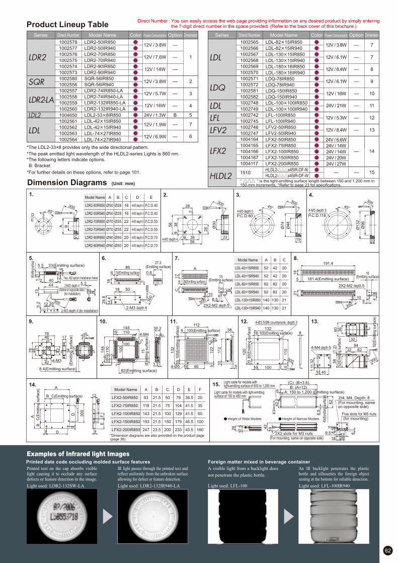
0.8
62
Examples of Infrared light ImagesPrinted date code occluding molded surface features Foreign matter mixed in beverage container
Printed text on the cap absorbs visible
light causing it to occlude any surface
defects or feature detection in the image.
Light used: LDR2-132SW-LA
IR light passes through the printed text and
reflect uniformly from the unbroken surface
allowing for defect or feature detection.
Light used: LDR2-132IR940-LA
A visible light from a backlight does
not penetrate the plastic bottle.
Light used: LFL-100
An IR backlight penetrates the plastic
bottle and silhouettes the foreign object
resting at the bottom for reliable detection.
Light used: LFL-100IR940
Direct Number : You can easily access the web page providing information on any desired product by simply entering the 7-digit direct number in the space provided. (Refer to the back cover of this brochure.)Product Lineup Table
Model NameDirect NumberSeries Power Consumption OptionColor Dimension
12V / 3.8W
12V / 7.6W
12V / 14W
12V / 3.8W
12V / 5.7W
12V / 16W
12V / 1.9W
12V / 6.9W
—
—
—
—
—
—
—
—
1
2
3
4
7
24V / 1.3W B 5
6
LDR2
LDR2!LA
LDL
LDL2
SQR
1002578
1002577
1002576
1002575
1002574
1002573
1002580
1002556
1002557
1002558
1002559
1002560
1002561
1002562
1002563
1002564
LDR2-50IR850
LDR2-50IR940
LDR2-70IR850
LDR2-70IR940
LDR2-90IR850
LDR2-90IR940
SQR-56IR850
SQR-56IR940
LDR2-74IR850-LA
LDR2-74IR940-LA
LDR2-132IR850-LA
LDR2-132IR940-LA
LDL-42X15IR850
1004650 LDL2-33X8IR850
LDL-42X15IR940
LDL-74X27IR850
LDL-74X27IR940
Model NameDirect NumberSeries Power Consumption OptionColor Dimension
—
—
—
—
—
—
—
—
7
7
8
9
10
11
12
13
—— 15
12V / 3.8W
12V / 6.1W
12V / 8.4W
12V / 6.1W
12V / 16W
24V / 21W
12V / 5.3W
12V / 8.4W
LDL
LFL
LFV2
LDL
LDQ
1002565
1002566
1002567
1002568
1002569
1002570
1002571
1002572
1002581
1002582
1002748
1002749
1002742
1002745
1002746
1002747
LDL-82X15IR850
LDL-82X15IR940
LDL-130X15IR850
LDL-130X15IR940
LDL-180X16IR850
LDL-180X16IR940
LDQ-78IR850
LDQ-78IR940
LDQ-150IR850
LDQ-150IR940
LDL-100X100IR850
LDL-100X100IR940
LFL-100IR850
LFL-100IR940
LFV2-50IR850
LFV2-50IR940
Dimension Diagrams (Unit: mm)
1.
C
BA
300
E
D45°
Ø30
300
4-M3 depth 4229 38
56
938
56
28
28
8.
16(Emitting surface)
2X2-M2 depth 5
300
181.4(Emitting surface)
191.4
5
18
10 49
9
21
Ø96
Ø132
300
P.C.D.116
4-M3 depth 5
22
45°
Ø48
Ø74
300
P.C.D.604-M3 depth 5
19
45°
34
(Em
itting s
urf
ace)
8.4(Emitting surface)
78
7846
42
36
3646
17
4-M3
42
300
15
(Em
ittin
g s
urf
ace
)
300
82(Emitting surface)
148
148
19
110
19 1104-M4
100
100
30.2
3.2
90°
10
112
5122
16
100(E
mitt
ing s
urf
ace
)
132
38
516 80
6 100(Emitting surface)
112
4-Ø5
300
8
4-Ø3.5/Ø6 countersink, depth 3
20
80(E
mitt
ing s
urf
ace
)
120
5110
16 100(Emitting surface)132
16 100
300
111
32
10 40
52(E
mitt
ing
surf
ace)
58
32 6294
3236
60
52(E
mitt
ing
surf
ace)
4-M4 depth 5
(1.2
)
A
Ø50
Ø50
Ø70
Ø70
Ø90
Ø90
B
Ø28
Ø28
Ø35
Ø35
Ø50
Ø50
D
4-M3 depth 4
4-M3 depth 4
4-M3 depth 5
4-M3 depth 5
4-M3 depth 4
4-M3 depth 4
E
P.C.D.40
P.C.D.40
P.C.D.50
P.C.D.50
P.C.D.70
P.C.D.70
C
16
16
22
22
20
20
LDR2-50IR850
LDR2-50IR940
LDR2-70IR850
LDR2-70IR940
LDR2-90IR850
LDR2-90IR940
Model Name
A
93
118
143
193
247
B
21.5
21.5
21.5
21.5
23.5
C
50
75
100
150
200
D
79
104
129
179
233
E
36.5
41.5
41.5
46.5
43.5
F
20
35
60
100
160
LFX2-50IR850
LFX2-75IR850
LFX2-100IR850
LFX2-150IR850
LFX2-200IR850
Model Name
*For further details on these options, refer to page 101.
*The following letters indicate options.
B: Bracket
*The LDL2-33!8 provides only the wide directional pattern.
2. 3. 4.
15.Light cable for models with light-emitting surface of 600 to 1,200 mm
42
A: 150 to 1,200 (Emitting surface)B: (A+12)
(C): (B+3.6)
6
45(E
mitt
ing
surfa
ce)
62
8.5
194
2
2X2 slots for M3 nuts(For mounting, same on opposite side)
68.5
9.5
18 2643
(for mounting)Five slots for M5 nuts
2X4, M4, Depth: 8
17.526
Light cable for models with light-emitting surface of 150 to 450 mm
HLDL21510
— 14
24V / 6.6W
24V / 14W
24V / 14W
24V / 20W
24V / 27W
LFX2
1004164
1004165
1004166
1004167
LFX2-50IR850
LFX2-75IR850
LFX2-100IR850
LFX2-150IR850
1004117 LFX2-200IR850
“ ” is the light-emitting surface length between 150 and 1,200 mm in 150-mm increments. *Refer to page 23 for specifications.
HLDL2- x45IR-DF-N
HLDL2- x45IR-DF-W
27.2(Emitting surface)
2-M3 depth 4
300
6
86
18
14.4
28.8
18 50
74(Emitting surface)
7.
9
2X2-M2 depth 5300
B(Emitting surface)
C
A
17
10
5
4
8.5
15(Emitting surface)
A
52
52
92
92
140
140
B
42
42
82
82
130
130
C
20
20
20
20
21
21
LDL-42!15IR850
LDL-42!15IR940
LDL-82!15IR850
LDL-82!15IR940
LDL-130!15IR850
LDL-130!15IR940
Model Name
5.5 33(Emitting surface)
8(Emi
tting s
urfac
e)
6
2 401.2
2.2 Two, M2 option installation holes
13
44
2-M3 depth 4 (for installation)
12 20
5.2
5.2
8
2XM2 depth 4 (Same on opposite side.)
(for installation)
300
5.
14.
6.
9. 10. 12. 13.11.
*The peak emitted light wavelength of the HLDL2-series Lights is 860 nm.
12
EF
7
A
A
C(Emitting surface)
C(E
mitt
ing
su
rfa
ce)
B
7 D
7D
B
300
*Dimension diagrams are also provided on the product page (page 38).
300
Height of Wide Models Height of Narrow Models
(For mounting, same on opposite side)
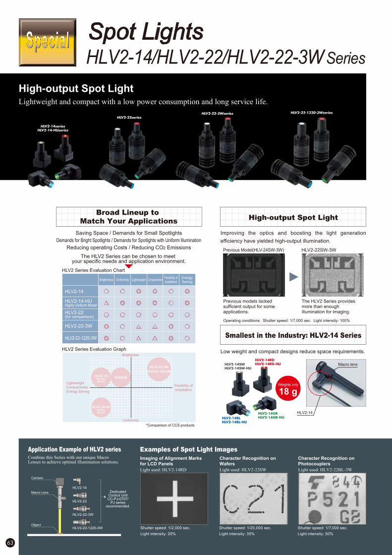
Broad Lineup to
Match Your ApplicationsHigh-output Spot Light
High-output Spot LightLightweight and compact with a low power consumption and long service life.
Improving the optics and boosting the light generation
efficiency have yielded high-output illumination.
Saving Space / Demands for Small Spotlights
Demands for Bright Spotlights / Demands for Spotlights with Uniform Illumination
Reducing operating Costs / Reducing CO2 Emissions
Application Example of HLV2 series Examples of Spot Light Images
Smallest in the Industry: HLV2-14 Series
Low weight and compact designs reduce space requirements.
HLV2!22!1220!3WseriesHLV2!22!3Wseries
HLV2!22series
HLV2!14series
HLV2!14!HUseries
Combine this Series with our unique Macro Lenses to achieve optimal illumination solutions.
DedicatedControl UnitCC-PJ-0707/
PJ seriesrecommended.
Object
Camera
Macro Lens
HLV2-22
HLV2-22-3W
HLV2-22-1220-3W
HLV2-14
Weights only
18 g
Imaging of Alignment Marks
for LCD Panels
Character Recognition on
Wafers
Character Recognition on
Photocouplers
Shutter speed: 1/2,000 sec.
Light intensity: 20%
Shutter speed: 1/7,000 sec.
Light intensity: 50%
Shutter speed: 1/20,000 sec.
Light intensity: 35%
Previous Model(HLV-24SW-3W) HLV2-22SW-3W
Previous models lacked sufficient output for some applications.
The HLV2 Series provides more than enough illumination for imaging.
HLV2!14RD
HLV2!14RD!HU
HLV2!14BL
HLV2!14BL!HU
HLV2!14SW
HLV2!14SW!HU
HLV2!14GR
HLV2!14GR!HU
HLV2-14
Macro lens
HLV2 Series Evaluation Chart
Brightness
HLV2-14
HLV2-14-HUHighly Uniform Model
HLV2-22(for comparison)
HLV2-22-3W
HLV2-22-1220-3W
Uniformity Lightweight CompactnessFlexibility of
Installation
Energy
Saving
HLV2 Series Evaluation Graph
*Comparison of CCS products
Brightness
Uniformity
Lightweight
Compactness
Energy Saving
Flexibility of
Installation
HLV2-14Standard
Models
HLV2-14-HUUniform
Models
HLV2-22-3W
HLV2-22-1220-3W
HLV2-22
The HLV2 Series can be chosen to meet your specific needs and application environment.
HLV2-14/HLV2-22/HLV2-22-3W Series
Spot Lights
Light used: HLV2-14RD Light used: HLV2-22BL-3WLight used: HLV2-22SW
Operating conditions: Shutter speed: 1/7,000 sec. Light intensity: 100%
63
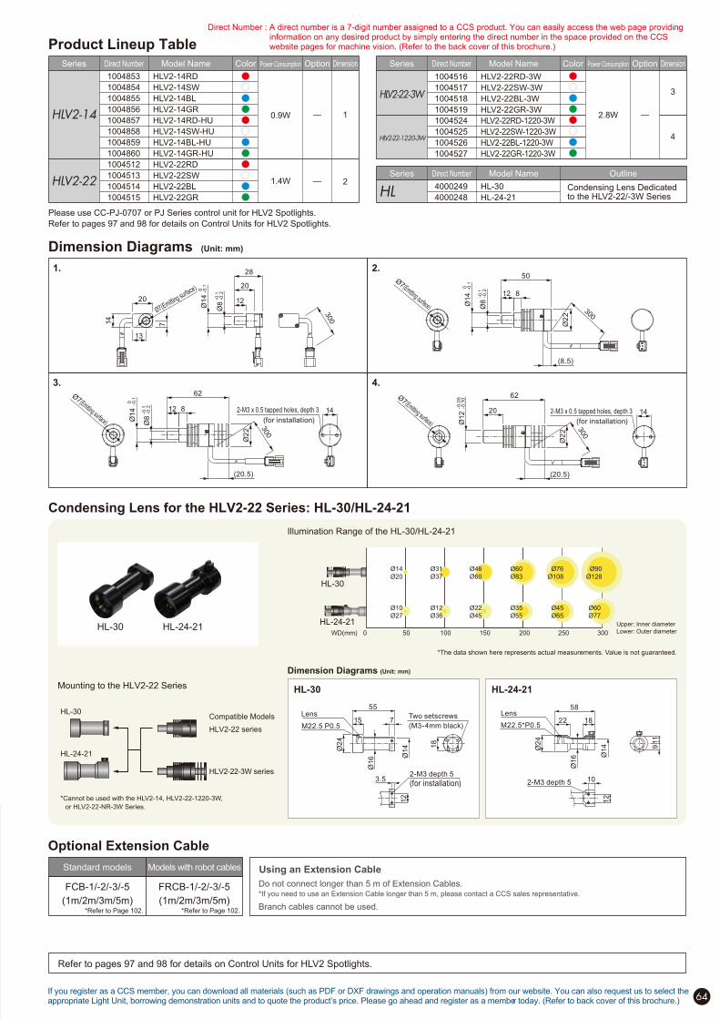
Product Lineup Table
Model NameDirect NumberSeries Power Consumption OptionColor Dimension
—
—
2
1
1.4W
0.9WHLV2!14
HLV2!22
1004853
1004854
1004855
1004856
1004857
1004858
1004859
1004860
1004512
1004513
1004514
1004515
HLV2-14RD
HLV2-14SW
HLV2-14BL
HLV2-14GR
HLV2-14RD-HU
HLV2-14SW-HU
HLV2-14BL-HU
HLV2-14GR-HU
HLV2-22RD
HLV2-22SW
HLV2-22BL
HLV2-22GR
Model NameDirect NumberSeries Power Consumption OptionColor Dimension
—
4
3
2.8W
HLV2!22!3W
HLV2!22!1220!3W
1004516
1004517
1004518
1004519
1004524
1004525
1004526
1004527
HLV2-22RD-3W
HLV2-22SW-3W
HLV2-22BL-3W
HLV2-22GR-3W
HLV2-22RD-1220-3W
HLV2-22SW-1220-3W
HLV2-22BL-1220-3W
HLV2-22GR-1220-3W
Model NameDirect NumberSeries Outline
HL4000249
4000248
HL-30
HL-24-21Condensing Lens Dedicated to the HLV2-22/-3W Series
Condensing Lens for the HLV2-22 Series: HL-30/HL-24-21
Illumination Range of the HL-30/HL-24-21
50 100 150 200 250 300WD(mm) 0
Ø14
Ø20
Ø31
Ø37
Ø46
Ø60
Ø60
Ø83
Ø76
Ø108
Ø90
Ø128
Ø10
Ø27
Ø12
Ø36
Ø22
Ø45
Ø35
Ø55
Ø45
Ø65
Ø60
Ø77
*The data shown here represents actual measurements. Value is not guaranteed.
Upper: Inner diameter
Lower: Outer diameter
HL-24-21
HL-30
HL-30 HL-24-21
Mounting to the HLV2-22 Series
*Cannot be used with the HLV2-14, HLV2-22-1220-3W,
or HLV2-22-NR-3W Series.
HL-30
HL-24-21
Compatible Models
HLV2-22 series
HLV2-22-3W series
HL-24-21HL-30
Dimension Diagrams (Unit: mm)
55
15 7
Ø2
4
Lens Two setscrews
(M3-4mm black)
Ø16
18
12
3.52-M3 depth 5
(for installation)
M22.5 P0.5
Ø14 Ø2
4
58
911
Ø16
Lens
M22.5*P0.522 18
Ø14
102-M3 depth 5
12
If you register as a CCS member, you can download all materials (such as PDF or DXF drawings and operation manuals) from our website. You can also request us to select the appropriate Light Unit, borrowing demonstration units and to quote the product’s price. Please go ahead and register as a member today. (Refer to back cover of this brochure.)
Dimension Diagrams (Unit: mm)
1. 2.
3.
Ø14
0 -0.1
Ø8
-0.1
-0.2
Ø7(Emitting surface)
20
14
13
7
28
12
20
62
(20.5)
Ø2
2
Ø14
0 -0.1
Ø8
-0.1
-0.2 12 8 142-M3 x 0.5 tapped holes, depth 3
Ø7(Emitting surface)
142-M3 x 0.5 tapped holes, depth 3
Ø7(Emitting surface)
62
20
Ø2
2
Ø12
-0.0
5-0
.10
(20.5)
Ø7(Emitting surface)
12
Ø2
2
Ø14
0 -0.1
Ø8
-0.1
-0.2
50
(8.5)
8
4.
(for installation)(for installation)
Refer to pages 97 and 98 for details on Control Units for HLV2 Spotlights.
Optional Extension Cable
Using an Extension Cable
Do not connect longer than 5 m of Extension Cables.*If you need to use an Extension Cable longer than 5 m, please contact a CCS sales representative.
Branch cables cannot be used.
FCB-1/-2/-3/-5
(1m/2m/3m/5m)
FRCB-1/-2/-3/-5
(1m/2m/3m/5m)
Standard models Models with robot cables
*Refer to Page 102. *Refer to Page 102.
Please use CC-PJ-0707 or PJ Series control unit for HLV2 Spotlights.
Refer to pages 97 and 98 for details on Control Units for HLV2 Spotlights.
64
300
300
300
300
Direct Number : A direct number is a 7-digit number assigned to a CCS product. You can easily access the web page providing information on any desired product by simply entering the direct number in the space provided on the CCS website pages for machine vision. (Refer to the back cover of this brochure.)

65 Direct Number : You can easily access the web page providing information on any desired product by simply entering the 7-digit direct number in the space provided. (Refer to the back cover of this brochure.)
HFS/HFR Series
A next generation illumination system that has advantages of both LED and fiber.
LED fiber system
Micro Fiber-heads
Our original light focusing technology
reaches unprecedented brightness
Clear images can be captured by selecting
illumination range, illumination angle and luminosity
Actual images of chip partWhile halogen fiber lighting illuminates a wide area, the HFR
Series using original-condensing techniques provides high
intensity by illuminating only a required field of view.
Image comparison of alignment of TAB tape
Detecting a small part that is difficult to capture with an
existing halogen light source can be achieved with high contrast
100W Halogen light + Ring light guide HFR-25-30 (Blue) LWD 30mm
Operating conditions: Shutter speed: 500!sec (1/20,000 sec.) Lens: Double magnification Light intensity: 100% Light used: HLV2-22BL-NR-3W
100W Halogen light + Ø20Ring light guide
HFR-25-30 (Blue) HFR-25-10 (Blue) HFR-40-20 (Blue)
The ring type HFR Series offers a wide
variety of products so that you can choose
the irradiation range, illumination angle,
and luminance most suitable for the objects
to be inspected and the environment.
Dimension Diagrams (Unit: mm)
Direct Number:1000127Direct Number:1000129
Direct Number:1000148 Direct Number:1000134
LWD: Light Working Distance (Distance from a light to an object)
Selectable in the lineup according the work sample character is tics.
Ø10
30
Ø5
10
20
Ø10
HFR-25-30
HFR-25-10
HFR-40-20
H i g h - c o n d e n s e d
illumination by Ø5 from
10mm LWD (high-
condensed illuminating
by single array)
Condensed illumination
from 30mm LWD
(condensed by single
array)
H i g h - c o n d e n s e d
illumination by wide-
view of Ø10 from 20mm
LWD (condensed by
three independent
arrays)
Light Source Receivers: 3 pcs.
P.C.D.30
4-M3 depth 4
Ø16
30
25
27
Ø14
38 500 28
12 8 8
18
Ø13
14
15
45
23
Ø40
21.5
2-Ø3.5/Ø6 Counterbore, thread depth 6
20
P.C.D
.20
Ø16
15
19
13
500
16 1212
14
Ø8
14
25
8 8
18
Ø13
15
2-Ø3.5/Ø6 Counterbore, thread depth 6
AD-HF (accessory)
2-M3 depth 3
Ø25
9
8
918
20
727
Ø6.12-M3 depth 4Ø8
12 23
35 500
Ø14
18
27
39
23 16
25
148 8
Ø8
Ø6 bond
diameter
Ø14
Ø10
2-Ø3.5/Ø6 Counterbore, thread depth 6
AD-HF (accessory)
HFR-40-20HFS-14-500 HFR-25-10
HFR-25-30

66
Allow users to choose the illumination color and intensityMicro Fiber-head combination ensures compatibility with a wide array of applications.
By changing the light source color, features can be
clearly extracted according to the application purpose
Red (RD), green (GR), blue (BL), and white (SW) light sources
are available for near monochromatic LED lighting that can be
matched to the spectral characteristics of the target object.
Combination with a Micro Fiber-head allows the user to tailor
the best illumination color and lighting configuration to extract
the most accurate image.
Straight type HFS-14-500
Change color with ease
HLV2-22-NR-3W Series for Micro-Fiber- heads are easily
attached and detached.
Please use with a connecting adaptor, AD-HF
Connecting Adapter (AD-HF) is included with the HFS/HFR Series
Application Example of HLV2-22-NR-3WMicro Fiber-head combination ensures compatibility with a wide array of applications
DedicatedControl UnitCC-PJ-0707/
PJ seriesrecommended.
HFS-14-500
HFR-25-10
HFR-25-30
Connecting adaptor (included)
AD-HF
Light source
HLV2-22-NR-3W
Ring type HFR-25-10/ HFR-25-30
HFS/HFR Series
A next generation illumination system that has advantages of both LED and fiber.
LED fiber system
Micro Fiber-heads
Our original light focusing technology
reaches unprecedented brightness
Clear images can be captured by selecting
illumination range, illumination angle and luminosity
Actual images of chip partWhile halogen fiber lighting illuminates a wide area, the HFR
Series using original-condensing techniques provides high
intensity by illuminating only a required field of view.
Image comparison of alignment of TAB tape
Detecting a small part that is difficult to capture with an
existing halogen light source can be achieved with high contrast
100W Halogen light + Ring light guide HFR-25-30 (Blue) LWD 30mm
Operating conditions: Shutter speed: 500!sec (1/20,000 sec.) Lens: Double magnification Light intensity: 100% Light used: HLV2-22BL-NR-3W
100W Halogen light + Ø20Ring light guide
HFR-25-30 (Blue) HFR-25-10 (Blue) HFR-40-20 (Blue)
The ring type HFR Series offers a wide
variety of products so that you can choose
the irradiation range, illumination angle,
and luminance most suitable for the objects
to be inspected and the environment.
Dimension Diagrams (Unit: mm)
Direct Number:1000127Direct Number:1000129
Direct Number:1000148 Direct Number:1000134
HLV2-22-NR-3W Series
Light Sources for Micro Fiber-heads
If you register as a CCS member, you can download all materials (such as PDF or DXF drawings and operation manuals) from our website. You can also request us to select the appropriate Light Unit, borrowing demonstration units and to quote the product’s price. Please go ahead and register as a member today. (Refer to back cover of this brochure.)
Using an Extension Cable
Do not connect longer than 5 m of
Extension Cables.*If you need to use an Extension Cable longer than
5 m, please contact a CCS sales representative.
Branch cables cannot be used.
Optional Extension Cable
FCB-1/-2/-3/-5
(1m/2m/3m/5m)
Standard models
FRCB-1/-2/-3/-5
(1m/2m/3m/5m)
Models with robot cables
Refer to pages 97 and 98 for details on Control Units for HLV2 Spotlights.
*Refer to Page 102.
*Refer to Page 102.
Product Lineup TableModel NameDirect NumberSeries Power Consumption OptionColor Dimension
— 1HLV2!22!NR!3W
1004520
1004521
1004522
1004523
HLV2-22RD-NR-3W
HLV2-22SW-NR-3W
HLV2-22BL-NR-3W
HLV2-22GR-NR-3W
2.8W
Dimension Diagrams (Unit: mm)
1.
(20.5)
Ø2
2
Ø14
0 -0.1 45
6 142-M3 x 0.5 tapped holes, depth 3
Ø10 (Emitting surface) (for installation)
Please use CC-PJ-0707 or PJ Series control unit for HLV2 Spotlights.
Refer to pages 97 and 98 for details on Control Units for Spotlight Units.
300
Direct Number : A direct number is a 7-digit number assigned to a CCS product. You can easily access the web page providing information on any desired product by simply entering the direct number in the space provided on the CCS website pages for machine vision. (Refer to the back cover of this brochure.)

Red Illumination Green Illumination
Blue Illumination Mixed Blue-Green Illumination
67
Blend the color as you wantPrecise color blending using CCS's mixing
chamber and three-channel power supply
Image Examples of Liquid Crystal Color Filters
The HLV2-3M-RGB-3W is an exclusive light source comprised
of a light source section and a blending unit. It enables
step-less, independent dimming of each color. The special
construction of the blending unit eliminates irregularities to
provide uniform light emission. Connection to a model from the
CCS Micro Fiber Head Ring Series allows you to create the
optimal illumination color for a variety of configurations.
The HLV2-22RD-NR-3W red light source, HLV2-22GR-NR-3W
green light source, and HLV2-22BL-NR-3W blue light source
are built into the HLV2-3M-RGB-3W. The R, G, and B light
sources can be independently controlled to create any
combination up to full-spectrum lighting. This ensures that the
best illumination color will be available for the spectroscopic
reflectivity of the workpiece.
Independent control of intensity provides the optimal
illumination according to the spectral characteristics of object.
Ring type HFR-25-10/ HFR-25-30Straight type HFS-14-500
HLV-3M (Blending unit)
Application Example of HLV2-3M-RGB-3WMicro Fiber-head combination ensures compatibility with a wide array of applications
DedicatedControl Unit
PJ-1505-3CArecommended.HFS-14-500
HFR-25-10
HFR-25-30
Light source
HLV2-3M-RGB-3W
Using an Extension Cable
Do not connect longer than 5 m of
Extension Cables.*If you need to use an Extension Cable longer than
5 m, please contact a CCS sales representative.
Branch cables cannot be used.
Optional Extension Cable
Allow users to tailor the illumination color to the target object
HLV2-3M-RGB-3W
Light Sources for Micro Fiber-heads
Micro Fiber-head combination ensures compatibility with a wide array of applications.
Increased intensity using CCS's second-generation high
intensity HLV2 light sourceHLV2-22RD-NR-3W
(Red light souce)
HLV2-22GR-NR-3W
(Green light souce)
HLV2-22BL-NR-3W
(Blue light souce)
FCB-1/-2/-3/-5
(1m/2m/3m/5m)
Standard models
FRCB-1/-2/-3/-5
(1m/2m/3m/5m)
Models with robot cables
*Refer to Page 102.
*Refer to Page 102.

68
Model NameDirect NumberSeries Power Consumption OptionColor Dimension
Product Lineup Table
— 18.4WHLV2!3M!RGB!3W 1004528 HLV2-3M-RGB-3W
Dimension Diagrams (Unit: mm)
1.
Ø22
13 72
0
2-M3x0.5tapped holes, depth5
(for installation)8312
26.530
2-Ø3.5/Ø6countersink, depth6
(for installation)
1427.527.5
31
HLV2-22RD-NR-3W
HLV2-22GR-NR-3W
HLV2-22BL-NR-3W
10
113
7
14
(1.2)26
Ø8
(Em
ittin
g su
rface
)
+0.
10
39
377
418
4-M3x0.5tapped holes, depth4
(for installation)
Ø14
If you register as a CCS member, you can download all materials (such as PDF or DXF drawings and operation manuals) from our website. You can also request us to select the appropriate Light Unit, borrowing demonstration units and to quote the product’s price. Please go ahead and register as a member today. (Refer to back cover of this brochure.)
Refer to pages 97 and 98 for details on Control Units for HLV2 Spotlights.
Please use CC-PJ-0707 or PJ Series control unit for HLV2 Spotlights.
Refer to pages 97 and 98 for details on Control Units for HLV2 Spotlights.30
0
Direct Number : A direct number is a 7-digit number assigned to a CCS product. You can easily access the web page providing information on any desired product by simply entering the direct number in the space provided on the CCS website pages for machine vision. (Refer to the back cover of this brochure.)
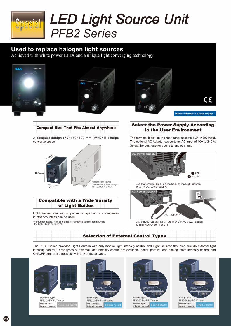
69
Used to replace halogen light sourcesAchieved with white power LEDs and a unique light converging technology.
Selection of External Control Types
Compact Size That Fits Almost Anywhere
A compact design (70!150!100 mm (W!D!H)) helps
conserve space.
The terminal block on the rear panel accepts a 24-V DC input.
The optional AC Adapter supports an AC input of 100 to 240 V.
Select the best one for your site environment.
The PFB2 Series provides Light Sources with only manual light intensity control and Light Sources that also provide external light
intensity control. Three types of external light intensity control are available: serial, parallel, and analog. Both intensity control and
ON/OFF control are possible with any of these types.
100 mm
150 mm
70 mm*A standard, 100-W halogenlight source is shown.
Halogen light source
Use the AC Adaptor for a 100 to 240-V AC power supply.(Model: ADP2460-PFB-JT)
AC Power Supply
AC Adaptor
External controlconnector(9 -pin D-sub connector)
External controlManual lightintensity controlNo external control
Manual lightintensity control
PFB2-20SW-F-PJT series
Parallel Type
External controlManual lightintensity control
PFB2-20SW-F-AJT series
Analog Type
External controlManual lightintensity control
PFB2-20SW-F-JT series
Standard Type
DC Power Supply
24 V DC
GND
Use the terminal block on the back of the Light Sourcefor 24-V DC power supply.
Compatible with a Wide Variety
of Light Guides
Light Guides from five companies in Japan and six companies
in other countries can be used
*For further details, refer to the adapter dimensions table for mounting the Light Guide on page 70.
PFB2-20SW-F-SJT series
Serial Type
PFB2 Series
LED Light Source Unit
Relevant information is listed on page3.
Select the Power Supply According
to the User Environment
External controlconnector(15 -pin D-sub connector)
External controlconnector(15 -pin D-sub connector)

70
6010
PFB2-20SW-F-JT-
PFB2-20SW-F-SJT-
PFB2-20SW-F-PJT-
PFB2-20SW-F-AJT-
Product Lineup Table
Series
PFB2
Power ConsumptionColor
15W
*Ask the manufacturer for details on Light Guides.
*Installation Method: Do not place anything within 50 mm of the fan exhaust outlet on the rear panel, the fan air inlets on the side panels, or the top panel.
AC Adaptor
Input: 100 to 240 V AC, 115 VA, 50/60 Hz
Output: 24 V DC, 60 W
50
AC Cord connector
IEC 60320 C6
Center plus
1530
Ø5.5
Ø2.1
116
31
10.5
Accessories: AC Cord
AC Adaptor (Model: ADP2460-PFB-JT)
S&E
External Control Cable (Model: EXCB2-9-9-3-ST)
9-pin, D-sub
socket
2x#4-40UNC
(inch screws)
2x#4-40UNC
(inch screws)
3000
9-pin, D-sub
socket
EIA-232 compliant
CN1 CN2
Frame Frame
(Serial Type)
External Control Cable (Model: EXCB2-B3)
Shield ground
D-sub, 15-pin
SCIC-0.18-16 Loose wires
on one end
(40.5
)
3000
Ø8.1
1 (black) 2 (white) 3 (red) 4 (green) 5 (yellow) 6 (brown) 7 (blue) 8 (purple) 9 (gray) 10 (pink) 11 (white/black) 12 (red/black) 13 (green/black) 14 (yellow/black) 15 (brown/black) Not connected (blue/black)
(Parallel Type or Analog Type)
*The dimensions of the light guide attachment adaptor depend on the light guide that you use.
For details, refer to information available on the Web or contact CCS.
*For dimensions, refer to the dimension diagrams of the PFB2 Series.
5.8 to 22.8* 150 (16)
100
8
29
Light guide
attachment adaptor
70
61
35
Light intensity
control knob Power switch
Error indicator
lamp (red)
Power lamp (blue)
Ø40
Light source unit
37.5 85
62
4
4-M4, tap depth: 6 (for mounting)
DC IN 24 V (DC jack)
DC IN 24 V (terminal block)
Rear View of PFB2-20SW-F-JT
DC IN 24 V (DC jack)
DC IN 24 V (terminal block)
External control connector
(9 -pin D-sub connector)
Rear View of PFB2-20SW-F-SJT
External control connector
(15 -pin D-sub connector)
DC IN 24 V (DC jack)
DC IN 24 V (terminal block)
Rear View of PFB2-20SW-F-PJT
External control connector
(15 -pin D-sub connector)
DC IN 24 V (DC jack)
DC IN 24 V (terminal block)
Rear View of PFB2-20SW-F-AJT
Dimension Diagrams (Unit: mm)
PFB2 series
Optional Accessories
Light Guide Attachment Adaptor Dimension Diagrams (Unit: mm)
Ø15.8
6
12.7
Ø11
.13
Ø6.3
5
Ø4
.72
12.7
Ø10.7
2 Ø7
.92
12.7
Ø15.6
Ø14.2
7
12.7
Ø15.8
75
31.65
Ø2
5 t
o 3
2
37
22.8
31Ø2
5 t
o 3
5
16.8
Ø2
0 t
o 3
1
21
6.8
Ø2
5
Ø2
0
Ø1
3
15
3015.8
Ø2
5 t
o 4
0 Ø15
Ø15
Ø15
Ø15
Ø15
Ø15
20
5.8
*Applicable only to CCS’s HFS/HFR-seriesMicro-fiber Heads.
Ø1
4 Ø8
12
17.8 17.45
11.5
Ø2
2.1
Ø18.2
Ø15.9
18.3
6.4
8
Ø1
8
22.2
15.8
Ø2
5 t
o 3
0
30
11.8
12.7
Ø1
8
Ø15.8
7
10.8
Ø2
2
Ø18.2
4
25
11.811.8
11.8 11.8
Reading Light Guide Mounting Adapter Dimensions
Ø25 to 3
2
Ø15
37
Light guide
22.8
Attachment adaptor
PFB2 Light Source
PFB2-20SW-F- -MO
The type is entered here:
JT, SJT, AJT, or PJT.
Light guide attachment adaptor
Reading Lineup Selection Table
PFB2-20SW-F-JT-
Model name The Light Guide Mounting Adapter is
specified here.
-MO/-NP/-MI/-HY/-SU/-VL/-TF/
-TE/-SH1/-SH2/-DJ1/-DJ2/-DJ3/
-DJ4/-CS1/-IT
JT/SJT/AJT/PJT
Model NameDirect Number
If you register as a CCS member, you can download all materials (such as PDF or DXF drawings and operation manuals) from our website. You can also request us to select the appropriate Light Unit, borrowing demonstration units and to quote the product’s price. Please go ahead and register as a member today. (Refer to back cover of this brochure.)
(Serial Type)
(Standard Type)
(Analog Type) (Parallel Type)
Direct Number : A direct number is a 7-digit number assigned to a CCS product. You can easily access the web page providing information on any desired product by simply entering the direct number in the space provided on the CCS website pages for machine vision. (Refer to the back cover of this brochure.)

71
SE-16/SE-18 Series
CCS Macro Lens provides high magnification and performance at a low costMagnification ranging from 0.5x to 6x and option for HLV2 Series coaxial light port.
Macro Lens
SE-16 Series with 0.5x, 1x, and 2x magnifications
Coaxial Port for HLV Series Light Straight Tube
Direct Number:4000516 Direct Number:4000517 Direct Number:4000518 Direct Number:4000520 Direct Number:4000521 Direct Number:4000522
Direct Number:4000524
Direct Number:4000515
Direct Number:4000526 Direct Number:4000527 Direct Number:4000528 Direct Number:4000529 Direct Number:4000530
SE-18 Series with 2x, 4x, and 6x magnifications
Full set
Combined use of lens unit, either optional magnification tube, and either mount changes magnification. Interchangeable mount allows for coaxial or external lighting.
Type: SE-16MS
Full set includes:
Straight mount
Coaxial mount
Lens unit
Lens barrel (short)
Lens barrel (long)
Coaxial Port for HLV Series LightStraight Tube
Full set
Combined use of C-mount ring with either lens unit either optional magnification tube changes magnification. Interchangeable lens unit allows for coaxial or external lighting.
Configuring system for desired magnification
Configuring system for desired magnification
Type: SE-18MS
Full set includes:
Straight lens unit
Coaxial lens unit
C mount ring
4x ring
6x ring
Type: SE-16SM05Magnification: 0.5 x
Type: SE-16SM1Magnification: 1 x
Type: SE-16SM2Magnification: 2 x
Type: SE-16VM05Magnification: 0.5 x
Type: SE-16VM1Magnification: 1 x
Type: SE-16VM2Magnification: 2 x
0.5 x 1 x 2 x 0.5 x 1 x 2 x
Lens barrel (short)
Straight mount
Coaxial mount
0.5x
1x
2x
Lens unit
Lens unit
Lens barrel (long) Lens unit
Type: SE-18SM2Magnification: 2x
Type: SE-18SM4Magnification: 4x
Type: SE-18SM6Magnification: 6x
Type: SE-18VM2Magnification: 2x
Type: SE-18VM4Magnification: 4x
Type: SE-18VM6Magnification: 6x
2x 4x 6x 2x 4x 6x
2x
4x
6x
C mount ring
Straight lens unit
Coaxial lens unit
4x ring C mount ring
6x ring C mount ring
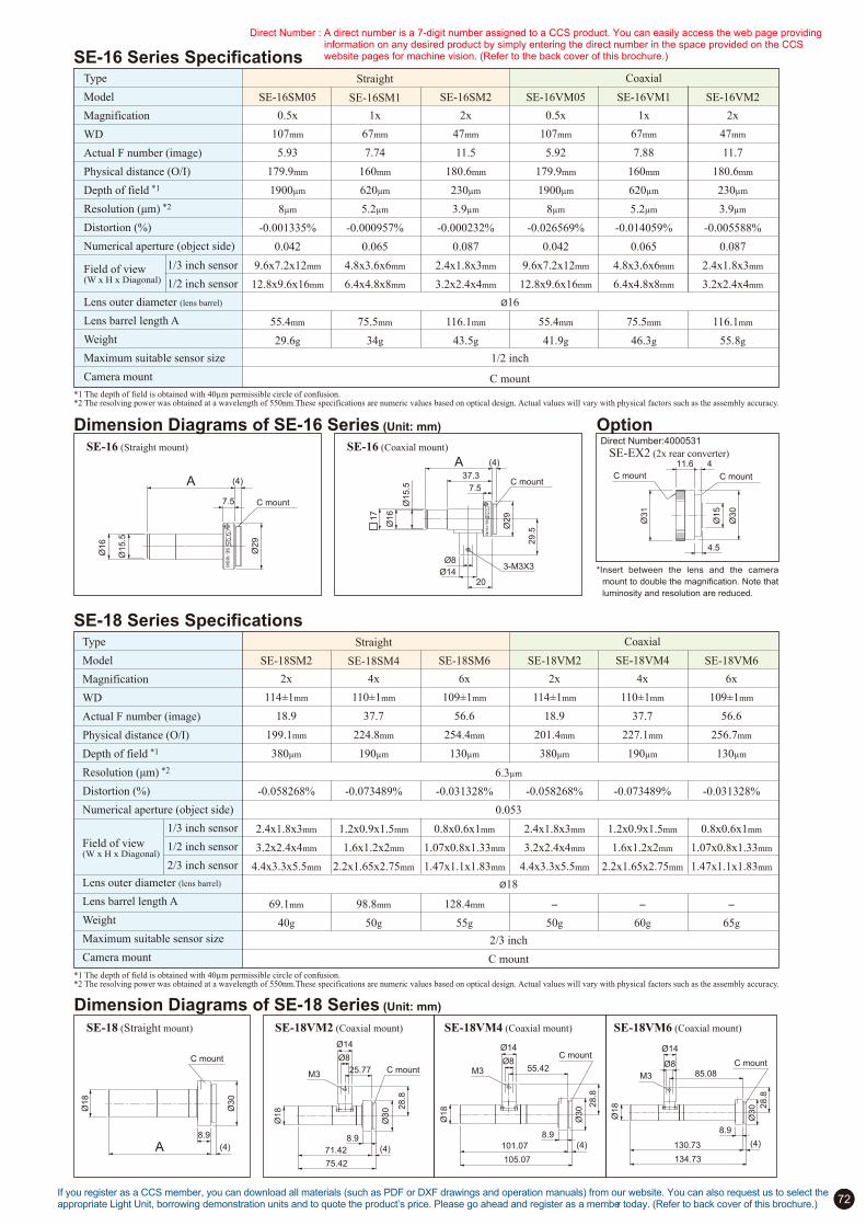
72
Direct Number:4000531
SE-16 Series Specifications
*1 The depth of field is obtained with 40!m permissible circle of confusion.*2 The resolving power was obtained at a wavelength of 550nm.These specifications are numeric values based on optical design. Actual values will vary with physical factors such as the assembly accuracy.
Type
Model
Magnification
WD
Actual F number (image)
Physical distance (O/I)
Depth of field *1
Resolution (µm) *2
Distortion (%)
Numerical aperture (object side)
Field of view(W x H x Diagonal)
Lens outer diameter (lens barrel)
Lens barrel length A
Weight
Maximum suitable sensor size
Camera mount
Straight
SE-16SM1
Coaxial
SE-16VM1SE-16VM05 SE-16VM2SE-16SM05 SE-16SM2
0.5x 1x 2x 0.5x 1x 2x
C mount
Ø16
1/2 inch
107mm
5.93
179.9mm
1900!m
8!m
-0.001335%
0.042
9.6x7.2x12mm
12.8x9.6x16mm
55.4mm
29.6g
67mm
7.74
160mm
620!m
5.2!m
-0.000957%
0.065
4.8x3.6x6mm
6.4x4.8x8mm
75.5mm
34g
47mm
11.5
180.6mm
230!m
3.9!m
-0.000232%
0.087
2.4x1.8x3mm
3.2x2.4x4mm
116.1mm
43.5g
107mm
5.92
179.9mm
1900!m
8!m
-0.026569%
0.042
9.6x7.2x12mm
12.8x9.6x16mm
55.4mm
41.9g
67mm
7.88
160mm
620!m
5.2!m
-0.014059%
0.065
4.8x3.6x6mm
6.4x4.8x8mm
75.5mm
46.3g
47mm
11.7
180.6mm
230!m
3.9!m
-0.005588%
0.087
2.4x1.8x3mm
3.2x2.4x4mm
116.1mm
55.8g
Dimension Diagrams of SE-16 Series (Unit: mm) OptionSE-16 (Straight mount) SE-16 (Coaxial mount)
SE-EX2 (2x rear converter)
*Insert between the lens and the camera
mount to double the magnification. Note that
luminosity and resolution are reduced.
SE-18 Series Specifications
*1 The depth of field is obtained with 40!m permissible circle of confusion.*2 The resolving power was obtained at a wavelength of 550nm.These specifications are numeric values based on optical design. Actual values will vary with physical factors such as the assembly accuracy.
Type
Model
Magnification
WD
Actual F number (image)
Physical distance (O/I)
Depth of field *1
Resolution (µm) *2
Distortion (%)
Numerical aperture (object side)
Field of view(W x H x Diagonal)
Lens outer diameter (lens barrel)
Lens barrel length A
Weight
Maximum suitable sensor size
Camera mount
Straight
SE-18SM4
Coaxial
SE-18VM4SE-18VM2 SE-18VM6SE-18SM2 SE-18SM6
2x 4x 6x 2x 4x 6x
2/3 inch
C mount
Ø18
114±1mm
18.9
199.1mm
380!m
-0.058268%
2.4x1.8x3mm
3.2x2.4x4mm
4.4x3.3x5.5mm
69.1mm
40g
110±1mm
37.7
224.8mm
190!m
-0.073489%
1.2x0.9x1.5mm
1.6x1.2x2mm
2.2x1.65x2.75mm
98.8mm
50g
109±1mm
56.6
254.4mm
130!m
-0.031328%
0.8x0.6x1mm
1.07x0.8x1.33mm
1.47x1.1x1.83mm
128.4mm
55g
114±1mm
18.9
201.4mm
380!m
-0.058268%
2.4x1.8x3mm
3.2x2.4x4mm
4.4x3.3x5.5mm
-
50g
110±1mm
37.7
227.1mm
190!m
-0.073489%
1.2x0.9x1.5mm
1.6x1.2x2mm
2.2x1.65x2.75mm
-
60g
109±1mm
56.6
256.7mm
130!m
-0.031328%
0.8x0.6x1mm
1.07x0.8x1.33mm
1.47x1.1x1.83mm
-
65g
0.053
6.3!m
Dimension Diagrams of SE-18 Series (Unit: mm)
SE-18 (Straight mount) SE-18VM2 (Coaxial mount) SE-18VM4 (Coaxial mount) SE-18VM6 (Coaxial mount)
1/3 inch sensor
1/2 inch sensor
1/3 inch sensor
1/2 inch sensor
2/3 inch sensor
SE
-16S
M
Ø29
Ø15.5
Ø16
C mount7.5
A (4)
11.6 4
4.5
Ø31
Ø30
Ø15
C mountC mount
SE
-16
VM
Ø29
Ø15.5
Ø16
C mount
Ø8
Ø1420
37.3
1
7
7.5
3-M3X3
29.5
A (4)
Ø30
Ø18
C mount
(4)
8.9
A
Ø30
Ø18
C mount
(4)71.42
8.9
25.77
75.42
28.8
M3
Ø14
Ø8
Ø30
Ø18
C mount
(4)
28.8
M3
Ø14
Ø855.42
8.9
101.07
105.07
C mount
Ø30
Ø18
(4)
28.8
M3
Ø14
Ø8
8.9
130.73
85.08
134.73
If you register as a CCS member, you can download all materials (such as PDF or DXF drawings and operation manuals) from our website. You can also request us to select the appropriate Light Unit, borrowing demonstration units and to quote the product’s price. Please go ahead and register as a member today. (Refer to back cover of this brochure.)
Direct Number : A direct number is a 7-digit number assigned to a CCS product. You can easily access the web page providing information on any desired product by simply entering the direct number in the space provided on the CCS website pages for machine vision. (Refer to the back cover of this brochure.)
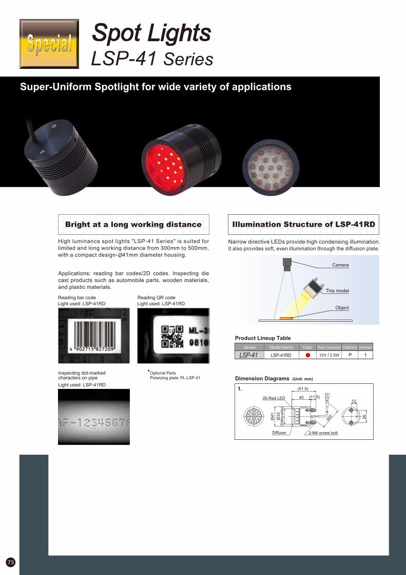
73
Spot LightsLSP-41 Series
Super-Uniform Spotlight for wide variety of applications
Bright at a long working distance Illumination Structure of LSP-41RD
High luminance spot lights "LSP-41 Series" is suited for
limited and long working distance from 300mm to 500mm,
with a compact design- 41mm diameter housing.
Applications; reading bar codes/2D codes. Inspecting die
cast products such as automobile parts, wooden materials,
and plastic materials.
Reading bar code Reading QR code
Light used: LSP-41RDLight used: LSP-41RD
Inspecting dot-markedcharacters on pipe
Light used: LSP-41RD
Optional PartsPolarizing plate: PL-LSP-41
Narrow directive LEDs provide high condensing illumination.
It also provides soft, even illumination through the diffusion plate.
LSP-41 LSP-41RD P 1
1.
Product Lineup Table
Dimension Diagrams (Unit: mm)
Series Model Name Color Power Consumption Options Dimension
12V / 2.0W
This model

74
Spot LightsLV Series
Lightweight, Compact
Spotlights LV Series
Weight:
40 g
50mm
Ø27mm
Low Power Consumption
The LV-series Spotlights consume only 0.7 W to help save
energy.
Application Example of LV seriesCombine this Series with our unique Macro Lenses to achieve optimal illumination solutions.
*The peak light frequency of the LV-27RD2 (red light) is 630 nm.*The peak light frequency of the LV-27-R (red light) is 623 nm.
Product Lineup Table
Model NameDirect NumberSeries Power ConsumptionColor Dimension
LV 1
24V / 0.8W
12V / 0.7W
12V / 0.7W
12V / 0.7W
12V / 0.7W
1002432
1002438
1002425
1002428
LV-27-R
1005548 LV-27RD2
LV-27-SW
LV-27-BL
LV-27-GR
Direct Number : A direct number is a 7-digit number assigned to a CCS product. You can easily access the web page providing information on any desired product by simply entering the direct number in the space provided on the CCS website pages for machine vision. (Refer to the back cover of this brochure.)
Dimension Diagrams (Unit: mm)
1.
Ø14
Ø8 300
Ø27
50
308
Ø6(Emitting surface)
Complete Lineup
The standard lineup includes LED colors of red, white, and
blue.
LV-27RD2(-R)
LV-27-GR
LV-27-BL
LV-27-SW
Lightweight, Compact Design
The low weight and compact design reduce space
requirements.
These Spotlights can be used to directly illuminate
workpieces, or they can be mounted on the coaxial
epi-illumination sections of macro lens or other devices.
Spotlights are available with an 8-mm diameter opening, and
optionally with 10-mm and 12-mm diameter openings.
Object
Camera
Macro Lens
LV-27
Existing RD-type Red Lights will be discontinued at the April 15, 2013. RD2-type Red Lights is recommended as replacement. The RD-type and RD2-type Lights have different input voltages. Always use a 24-VDC Control Unit with RD2-type Lights. For a comparison between the RD-type and RD2-type Lights, refer to page 1.
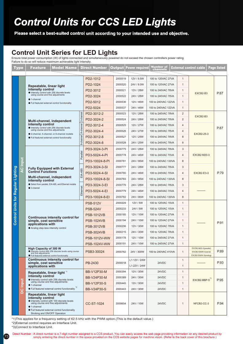
Control Unit Series for LED Lights
75
Type Feature Page listedPower requiredOutputDirect Number External control cableNumber of channels
Model Name
Ensure total power consumption (W) of lights connected and simultaneously powered do not exceed the chosen controllers power rating.
Failure to do so will reduce maximum achievable light intensity.
AC
In
pu
t
Co
ntr
ol
Un
its f
or
Reg
ula
r L
igh
tin
g
DC
In
pu
t
*1)This applies for a frequency setting of 62.5 kHz with the PWM option.(This is the default value.)
*2)External control requires an Interface Unit.
*3)Connect to Interface Unit.
1
1
1
1
1
1
2
2
4
4
8
8
2000519
2000520
2000521
2000522
2000536
2000537
2000523
2000524
2000525
2000526
2000527
2000528
PD2-1012
PD2-1024
PD2-3012
PD2-3024
PD2-5012
PD2-5024
PD2-3012-2
PD2-3024-2
PD2-3012-4
PD2-3024-4
PD2-3012-8
PD2-3024-8
100 to 120VAC 27VA
100 to 120VAC 27VA
100 to 240VAC 78VA
100 to 240VAC 78VA
100 to 240VAC 122VA
100 to 240VAC 122VA
100 to 240VAC 78VA
100 to 240VAC 78VA
100 to 240VAC 78VA
100 to 240VAC 78VA
100 to 240VAC 78VA
100 to 240VAC 78VA
12V / 9.5W
24V / 9.0W
12V / 28W
24V / 28W
12V / 46W
24V / 46W
12V / 28W
24V / 28W
12V / 27W
24V / 27W
12V / 25W
24V / 25W
EXCB2-25-3
P.87
P.87
EXCB2-B3
EXCB2-B3
Intensity control with 256 discrete levels using course and fine adjustments
Repeatable, linear light intensity control
Multi-channel, independent intensity control
Intensity control with 256 discrete levels using course and fine adjustments
2-c
hannel
4-c
hannel
8-c
hannel2-channel, 4-channel, or 8-channel models
Full featured external control functionality
1-channel
Full featured external control functionality
1
1
1
1
1
1
1
1
2000229
2000233
2000185
2000194
2000206
2000215
2000178
2000191
PSB-512V
PSB-524V
PSB-1012VB
PSB-1024VB
PSB-3012VB
PSB-3024VB
PSB-1012V-WW
PSB-1024V-WW
100 to 120VAC 15VA
100 to 120VAC 15VA
100 to 120VAC 27VA
100 to 120VAC 27VA
100 to 120VAC 78VA
100 to 120VAC 78VA
100 to 240VAC 27VA
100 to 240VAC 27VA
12V / 5W
24V / 5W
12V / 10W
24V / 10W
12V / 30W
24V / 30W
12V / 10W
24V / 10W
P.91
Continuous intensity control for simple, cost sensitive applications with
Analog step-less intensity control
Continuous intensity control for simple, cost sensitive applications with
1
1
1
1
2000394
2000389
2000445
2000443
BB-V12P30-M
BB-V24P30-M
BB-V12P30-S
BB-V24P30-S
24VDC
24VDC
24VDC
24VDC
12V / 30W
24V / 30W
12V / 30W
24V / 30W
P.95*3
EXCB2-BBP-5
CC-ST-1024 2000654 P.9424V / 10W 24VDC 1 NFCB2-CC-3
PB-2430 2000018 P.9324VDC1
1
Intensity control with 100 discrete levels using course and fine adjustments
1-channel
Full featured external control functionality
Strobing and ON/OFF Operation
Repeatable, linear light intensity control
*1
Intensity control with 256 discrete levels using course and fine adjustments
Repeatable, linear light intensity control
*2
L1:22V / 24W
L1:12V / 24W
High Capacity of 300 WP.89
EXCB2-M20-3(parallel)
EXCB2-E6SR-3(serial)
EXCB2-E6AN-3(analog)
PSB3-30024 2000762 24V / 300W 100 to 240VAC 410VA 1Intensity control with 256 discrete levels using course and fine adjustments
1-channel
Full featured external control functionality
Full featured external control functionality
Multi-channel, independent intensity control
Fully Equipped with External Control Functions
Select from parallel, EIA-485, and Ethernet models
3-channel
Pa
ralle
lE
IA-4
85
Eth
ern
et
3
4
8
3
4
8
3
4
8
2000775
2000778
2000781
2000777
2000780
2000783
2000776
2000779
2000782
PD3-3024-3-PI
PD3-5024-4-PI
PD3-10024-8-PI
PD3-3024-3-SI
PD3-5024-4-SI
PD3-10024-8-SI
PD3-3024-3-EI
PD3-5024-4-EI
PD3-10024-8-EI
100 to 240VAC 78VA
100 to 240VAC 70VA
100 to 240VAC 130VA
100 to 240VAC 78VA
100 to 240VAC 70VA
100 to 240VAC 130VA
100 to 240VAC 78VA
100 to 240VAC 70VA
100 to 240VAC 130VA
24V / 28W
24V / 46W
24V / 95W
24V / 28W
24V / 46W
24V / 95W
24V / 28W
24V / 46W
24V / 95W
P.79
EXCB2-M20-3
EXCB2-E3-3
Direct Number : A direct number is a 7-digit number assigned to a CCS product. You can easily access the web page providing information on any desired product by simply entering the direct number in the space provided on the CCS website pages for machine vision. (Refer to the back cover of this brochure.)

76If you register as a CCS member, you can download all materials (such as PDF or DXF drawings and operation manuals) from our website. You can also request us to select the appropriate Light Unit, borrowing demonstration units and to quote the product’s price. Please go ahead and register as a member today. (Refer to back cover of this brochure.)
Type Feature Page listedPower requiredOutputDirect Number External control cableNumber of channels
Model Name
AC
In
pu
tD
C I
np
utS
tro
be c
on
tro
l u
nit
Strobe length: 10 to 990 !s
2-channel
Strobing with overdrive 2
2
2000540
2000541
PTU2-3012
PTU2-3024
100 to 240VAC 78VA
100 to 240VAC 78VA
EXCB2-25-3
18V / 27W
48V / 27W
P.92
P.79
EXCB2-M20-3
EXCB2-E3-3
3
4
8
3
4
8
3
4
8
2000775
2000778
2000781
2000777
2000780
2000783
2000776
2000779
2000782
PD3-3024-3-PI
PD3-5024-4-PI
PD3-10024-8-PI
PD3-3024-3-SI
PD3-5024-4-SI
PD3-10024-8-SI
PD3-3024-3-EI
PD3-5024-4-EI
PD3-10024-8-EI
100 to 240VAC 78VA
100 to 240VAC 70VA
100 to 240VAC 130VA
100 to 240VAC 78VA
100 to 240VAC 70VA
100 to 240VAC 130VA
100 to 240VAC 78VA
100 to 240VAC 70VA
100 to 240VAC 130VA
24V / 28W
24V / 46W
24V / 95W
24V / 28W
24V / 46W
24V / 95W
24V / 28W
24V / 46W
24V / 95W
*7
Strobing without overdrive
Strobe length: 40 !s to 40 ms
3-channel
BB-V12S30-M
BB-V24S30-M
BB-V12S30-S
BB-V24S30-S
BB-V12P30-M
BB-V24P30-M
BB-V12P30-S
BB-V24P30-S
Strobe length: 0.001 to 1 ms
1-channel
Strobing with overdrive
Strobe length: 0.1 to 100 ms
1-channel
Strobing without overdrive*4
2000395
2000390
2000446
2000444
2000394
2000389
2000445
2000443
EXCB2-BBP-5
EXCB2-BBP-5
24VDC
24VDC
24VDC
24VDC
24VDC
24VDC
24VDC
24VDC
1
1
1
1
1
1
1
1
18V / 30W
48V / 30W
18V / 30W
48V / 30W
12V / 30W
24V / 30W
12V / 30W
24V / 30W
*3
*3
P.95
P.95
*8
Connecting to your current control unit for strobing(Strobing without overdrive)
STU-3000 2000366 P.92
CC-ST-1024 2000654 24V / 10W 24VDC NFCB2-CC-31 P.94
PS-3012-D24 2000157 18V / 30W 24VDC 1 P.93
Strobe length: 0.01 to 99.99 ms
*5
*6Strobe length: 50 !s to 40 ms
1-channel
Strobing without overdrive
*4)This applies when Trigger Mode is set for the PWM option.
*5)This applies when the switch is set to Strobe Mode.
*6)The selections are 50 !s, 100 !s, 250 !s, 500 !s, 1 ms, 4 ms, 10 ms, and 40 ms.
*7)The selections are 40 !s, 80 !s, 120 !s, 200 !s, 600 !s, 1 ms, 4 ms, 10 ms, 20 ms, and 40 ms.
*8)The following Control Units are supported: PD2-1012, PD2-1024, PD2-3012, PD2-1024, PD2-5012, PD2-5024, PD2-3012-2, and PD2-3024-2.
* Other optional Control Units have different units for strobe times.
* Overdrive boosts the voltage and current supplied to the Light to produce a higher output.
De
dic
ate
d C
on
tro
l U
nit PJ-1505-2CA
PJ-1505-3CA
PJ-1505-2CD24
PJ-1505-3CD24
100 to 240VAC 27VA
100 to 240VAC 37VA
24VDC
24VDC
2000131
2000136
2000134
2000139DC
Inpu
tA
C In
put
HL
V2
2
3
2
3
P.98EXCB2-B3
CC-PJ-0707 24VDC2000756
DC
In
pu
t HLV2 Series dedicated Controller
1 P.97NFCB2-CC-3
HLV2 Series dedicated control unit
2-channel, or 3-channel type
Analog step-less intensity control
External control function incorporated
1-channelIntensity control with 100 discrete levels using course and fine adjustments
Full featured external control functionalityStrobing and ON/OFF Operation

PD2-1012
2000519
12 V
9.5 W
1
Constant lighting
PWM control
62.5 kHz
256 levels
100 to 240 VAC
50/60 Hz
27 VA
-
-
-
-
-
-
- (Not covered by CE.)
700 g
Natural air cooling
Bottom
P. 87 to 88
PD2-3012
2000521
12 V
28 W
1
Constant lighting
PWM control
62.5 kHz
256 levels
100 to 240 VAC
50/60 Hz
78 VA
-
-
-
-
-
-
1.1 kg
Natural air cooling
Bottom or side
P. 87 to 88
2000523
12 V
28 W
2
Constant lighting
PWM control
62.5 kHz
256 levels
100 to 240 VAC
50/60 Hz
78 VA
-
-
-
-
-
-
1.1 kg
Natural air cooling
Bottom or side
P. 87 to 88
PD2-3012-2 PD2-3012-4
2000525
12 V
27 W
4
Constant lighting
PWM control
62.5 kHz
256 levels
100 to 240 VAC
50/60 Hz
78 VA
-
-
-
-
-
-
1.2 kg
Natural air cooling
Bottom or side
P. 87 to 88
PD2-3012-8
2000527
12 V
25 W
8
Constant lighting
PWM control
62.5 kHz
256 levels
100 to 240 VAC
50/60 Hz
78 VA
-
-
-
-
-
-
1.5 kg
Natural air cooling
Bottom or side
P. 87 to 88
PD2-5012
2000536
12 V
46 W
1
Constant lighting
PWM control
62.5 kHz
256 levels
100 to 240 VAC
50/60 Hz
122 VA
-
-
-
-
-
-
1.3 kg
Forced air cooling
Bottom or side
P. 87 to 88
PSB3-30024
2000762
24 V
300 W
1
Constant lighting
Variable-voltage control
-
256 levels
100 to 240 VAC
50/60 Hz
410 VA
-
-
-
-
2.3 kg
Natural air cooling
Bottom
P. 89 to 90
PSB-1024V-WW
2000191
24 V
10 W
1
Constant lighting
Variable-voltage control
-
Stepless
100 to 240 VAC
50/60 Hz
27 VA
-
-
-
-
-
-
-
-
-
470 g
Natural air cooling
Bottom
P. 91
2000233
24 V
5 W
1
Constant lighting
Variable-voltage control
-
Stepless
100 to 120 VAC
50/60Hz
15 VA
-
-
-
-
-
-
-
-
-
- (Not covered by CE.)
420 g
Natural air cooling
Bottom
P. 91
PSB-524V
2000194
24 V
10 W
1
Constant lighting
Variable-voltage control
-
Stepless
100 to 120 VAC
50/60Hz
27 VA
-
-
-
-
-
-
-
-
-
- (Not covered by CE.)
470 g
Natural air cooling
Bottom
P. 91
PSB-1024VB PSB-3024VB
2000215
24 V
30 W
1
Constant lighting
Variable-voltage control
-
Stepless
100 to 120 VAC
50/60Hz
78 VA
-
-
-
-
-
-
-
-
-
700 g
Natural air cooling
Bottom
P. 91
Control Unit SpecificationsModel
Direct number
Output voltage
Output power
Number of channels
Lighting method
Light intensity control method
PWM frequency
Light intensity control value
Input voltage
Frequency
Power consumption
Parallel communications
EIA-485 communications
Ethernet
Analog input
External intensity control
ON/OFF lighting
Strobe lighting
Lighting time
Lighting delay time
CE Marking
Weight
Cooling method
Mounting method
Page
External control m
ethod E
xte
rnal c
ontro
l functio
ns
Model
Direct number
Output voltage
Output power
Number of channels
Lighting method
Light intensity control method
PWM frequency
Light intensity control value
Input voltage
Frequency
Power consumption
Parallel communications
EIA-485 communications
Ethernet
Analog input
External intensity control
ON/OFF lighting
Strobe lighting
Lighting time
Lighting delay time
CE Marking
Weight
Cooling method
Mounting method
Page
External control m
ethod E
xte
rna
l contro
l fun
ctio
ns
* Special Control Units are not included.
*The PSB Series also includes a model that has an optional intensity control knob.
*For the BB Series, you can select between 62.5 kHz (intensity level 256), 125 kHz (intensity level 128), 250 kHz (intensity level 64), or 500 kHz (intensity level 32) for the lighting frequency.
2000520
24 V
9 W
1
Constant lighting
PWM control
62.5kHz
256 levels
100 to 120 VAC
50/60 Hz
27 VA
-
-
-
-
-
-
- (Not covered by CE.)
700 g
Natural air cooling
Bottom
P. 87 to 88
PD2-1024
2000522
24 V
28 W
1
Constant lighting
PWM control
62.5kHz
256 levels
100 to 240 VAC
50/60 Hz
78 VA
-
-
-
-
-
-
1.1 kg
Natural air cooling
Bottom or side
P. 87 to 88
PD2-3024
2000524
24 V
28 W
2
Constant lighting
PWM control
62.5kHz
256 levels
100 to 240 VAC
50/60 Hz
78 VA
-
-
-
-
-
-
1.1 kg
Natural air cooling
Bottom or side
P. 87 to 88
PD2-3024-2
2000526
24 V
27 W
4
Constant lighting
PWM control
62.5kHz
256 levels
100 to 240 VAC
50/60 Hz
78 VA
-
-
-
-
-
-
1.2 kg
Natural air cooling
Bottom or side
P. 87 to 88
PD2-3024-4
2000528
24 V
25 W
8
Constant lighting
PWM control
62.5kHz
256 levels
100 to 240 VAC
50/60 Hz
78 VA
-
-
-
-
-
-
1.5 kg
Natural air cooling
Bottom or side
P. 87 to 88
PD2-3024-8
2000537
24 V
46 W
1
Constant lighting
PWM control
62.5kHz
256 levels
100 to 240 VAC
50/60 Hz
122 VA
-
-
-
-
-
-
1.3 kg
Forced air cooling
Bottom or side
P. 87 to 88
PD2-5024
(Without overdrive)
2000775
24 V
28 W
3
Constant and strobe lighting
PWM and lighting time control
125kHz
256 levels
100 to 240 VAC
50/60 Hz
78 VA
-
-
-
10µs max.
600 g
Natural air cooling
Bottom or DIN rail
P. 79 to 86
PD3-3024-3-PI
40 µs/80 µs/120 µs/
200 µs/600 µs/1 ms/4 ms/
10 ms/20 ms/40 ms
(Without overdrive)
2000777
24 V
28 W
3
Constant and strobe lighting
PWM and lighting time control
125kHz
256 levels
100 to 240 VAC
50/60 Hz
78 VA
-
-
-
10µs max.
600 g
Natural air cooling
Bottom or DIN rail
P. 79 to 86
PD3-3024-3-SI
40 µs/80 µs/120 µs/
200 µs/600 µs/1 ms/4 ms/
10 ms/20 ms/40 ms
(Without overdrive)
2000776
24 V
28 W
3
Constant and strobe lighting
PWM and lighting time control
125kHz
256 levels
100 to 240 VAC
50/60 Hz
78 VA
-
-
-
10µs max.
600 g
Natural air cooling
Bottom or DIN rail
P. 79 to 86
PD3-3024-3-EI
40 µs/80 µs/120 µs/
200 µs/600 µs/1 ms/4 ms/
10 ms/20 ms/40 ms
(Without overdrive)
2000778
24 V
46 W
4
Constant and strobe lighting
PWM and lighting time control
125kHz
256 levels
100 to 240 VAC
50/60 Hz
70 VA
-
-
-
20µs max.
1.2 kg
Forced air cooling
Bottom or DIN rail
P. 79 to 86
PD3-5024-4-PI
40 µs/80 µs/120 µs/
200 µs/600 µs/1 ms/4 ms/
10 ms/20 ms/40 ms
(Without overdrive)
2000780
24 V
46 W
4
Constant and strobe lighting
PWM and lighting time control
125kHz
256 levels
100 to 240 VAC
50/60 Hz
70 VA
-
-
-
20µs max.
1.2 kg
Forced air cooling
Bottom or DIN rail
P. 79 to 86
PD3-5024-4-SI
40 µs/80 µs/120 µs/
200 µs/600 µs/1 ms/4 ms/
10 ms/20 ms/40 ms
Digital Control Unit Analog Control Unit
77Direct Number : A direct number is a 7-digit number assigned to a CCS product. You can easily access the web page providing information on any desired product by
simply entering the direct number in the space provided on the CCS website pages for machine vision. (Refer to the back cover of this brochure.)

10!s to 1 ms
(Pulse width control
by potentiometer)
(With overdrive)
2000157
18 V
30 W
1
Strobe lighting
Lighting time control
-
-
24 VDC
-
20 W
-
-
-
-
-
-
10 µs max.
650 g
Natural air cooling
DIN rail
P. 93
PS-3012-D24 PTU2-3012
(With overdrive)
2000540
18 V
27 W
2
Strobe lighting
Lighting time control
-
10% to 100%(10% increments)
100 to 240 VAC
50/60 Hz
78 VA
-
-
-
-
15 µs max.
1.2 kg
Natural air cooling
Bottom
P. 92
10 to 990 !s
(10-!s increments, can be set
via the front-panel switch only)
Model
Direct number
Output voltage
Output power
Number of channels
Lighting method
Light intensity control method
PWM frequency
Light intensity control value
Input voltage
Frequency
Power consumption
Parallel communications
EIA-485 communications
Ethernet
Analog input
External intensity control
ON/OFF lighting
Strobe lighting
Lighting time
Lighting delay time
CE Marking
Weight
Cooling method
Mounting method
Page
External control m
ethod E
xte
rnal c
ontro
l functio
ns
Model
Direct number
Output voltage
Output power
Number of channels
Lighting method
Light intensity control method
PWM frequency
Light intensity control value
Input voltage
Frequency
Power consumption
Parallel communications
EIA-485 communications
Ethernet
Analog input
External intensity control
ON/OFF lighting
Strobe lighting
Lighting time
Lighting delay time
CE Marking
Weight
Cooling method
Mounting method
Page
External control m
ethod E
xte
rnal c
ontro
l functio
ns
(Uses Interface Unit.)
2000389
24 V
30 W
1
Constant and strobe lighting
PWM and lighting time control
62.5 kHz (Default)
256 levels (default value)
24 VDC
-
42 W
-
-
-
3 µs max.
350 g
Natural air cooling
DIN rail
P. 95 to 96
BB-V24P30-M
0.1 to 100 ms (set via the front-panel
button only)
(Without overdrive) (With overdrive)
2000390
48 V
30 W
1
Strobe lighting
Lighting time control
-
-
24 VDC
-
-
-
-
-
-
0.001 to 1 ms
1 to 1,000 !s
400 g
Natural air cooling
DIN rail
P. 95 to 96
BB-V24S30-M
16 W (average power consumption),
26 W (peak power consumption)
(Uses Interface Unit.)
(With overdrive)
2000444
48 V
30 W
1
Strobe lighting
Lighting time control
-
-
24 VDC
-
-
-
-
-
-
0.001 to 1 ms
1 to 1,000 !s
400 g
Natural air cooling
DIN rail
P. 95 to 96
BB-V24S30-S
16 W (average power consumption),
26 W (peak power consumption)
(Uses Interface Unit.)(Uses Interface Unit.)
2000443
24 V
30 W
1
Constant and strobe lighting
PWM and lighting time control
62.5 kHz (Default)
256 levels (default value)
24 VDC
-
42 W
-
-
-
3µs max.
350 g
Natural air cooling
DIN rail
P. 95 to 96
BB-V24P30-S
0.1 to 100 ms (set via the front-panel button
on the Master Unit only)
(Without overdrive) (Without overdrive)
2000654
24 V
10 W
1
Constant and strobe lighting
PWM and lighting time control
100 kHz
100 levels
24 VDC
-
11 W
-
-
-
-
-
3 µs max.
- (Not covered by CE.)
80 g
Natural air cooling
DIN rail
P. 94
CC-ST-1024
50 µs/100 µs/
250 µs/500 µs/
1 ms/4 ms/10 ms/40 ms
2000018
L1:12V / L2:24 V
30 W
2
Constant lighting
Variable-voltage control
-
Stepless
24 VDC
-
36W
-
-
-
-
-
-
-
-
-
300 g
Natural air cooling
Bottom
P. 93
PB-2430
2000541
48 V
27 W
2
Strobe lighting
Lighting time control
-
10% to 100% (10% increments)
100 to 240 VAC
50/60 Hz
78 VA
-
-
-
-
15 µs max.
1.2 kg
Natural air cooling
Bottom
P. 92
PTU2-3024
10 to 990 !s
(10-!s increments, can be set
via the front-panel switch only)
(With overdrive)(Without overdrive)
2000779
24 V
46 W
4
Constant and strobe lighting
PWM and lighting time control
125kHz
256 levels
100 to 240 VAC
50/60 Hz
70 VA
-
-
-
20µs max.
1.2 kg
Forced air cooling
Bottom or DIN rail
P. 79 to 86
PD3-5024-4-EI
40 µs/80 µs/120 µs/
200 µs/600 µs/1 ms/4 ms/
10 ms/20 ms/40 ms
(Without overdrive)
2000781
24 V
95 W
8
Constant and strobe lighting
PWM and lighting time control
125kHz
256 levels
100 to 240 VAC
50/60 Hz
130 VA
-
-
-
20µs max.
1.5 kg
Forced air cooling
Bottom or DIN rail
P. 79 to 86
PD3-10024-8-PI
40 µs/80 µs/120 µs/
200 µs/600 µs/1 ms/4 ms/
10 ms/20 ms/40 ms
(Without overdrive)
2000783
24 V
95 W
8
Constant and strobe lighting
PWM and lighting time control
125kHz
256 levels
100 to 240 VAC
50/60 Hz
130 VA
-
-
-
20µs max.
1.5 kg
Forced air cooling
Bottom or DIN rail
P. 79 to 86
PD3-10024-8-SI
40 µs/80 µs/120 µs/
200 µs/600 µs/1 ms/4 ms/
10 ms/20 ms/40 ms
(Without overdrive)
2000782
24 V
95 W
8
Constant and strobe lighting
PWM and lighting time control
125kHz
256 levels
100 to 240 VAC
50/60 Hz
130 VA
-
-
-
20µs max.
1.5 kg
Forced air cooling
Bottom or DIN rail
P. 79 to 86
PD3-10024-8-EI
40 µs/80 µs/120 µs/
200 µs/600 µs/1 ms/4 ms/
10 ms/20 ms/40 ms
2000229
12 V
5 W
1
Constant lighting
Variable-voltage control
-
Stepless
100 to 120 VAC
50/60 Hz
15 VA
-
-
-
-
-
-
-
-
-
- (Not covered by CE.)
420 g
Natural air cooling
Bottom
P. 91
PSB-512V
2000185
12 V
10 W
1
Constant lighting
Variable-voltage control
-
Stepless
100 to 120 VAC
50/60 Hz
27 VA
-
-
-
-
-
-
-
-
-
- (Not covered by CE.)
470 g
Natural air cooling
Bottom
P. 91
PSB-1012VB
2000446
18 V
30 W
1
Strobe lighting
Lighting time control
-
-
24 VDC
-
-
-
-
-
-
0.001 to 1 ms
1 to 1,000 !s
400 g
Natural air cooling
DIN rail
P. 95 to 96
BB-V12S30-S
16 W (average power consumption),
72 W (peak power consumption)
(Uses Interface Unit.)
2000395
18 V
30 W
1
Strobe lighting
Lighting time control
-
-
24 VDC
-
-
-
-
-
-
0.001 to 1 ms
1 to 1,000 !s
400 g
Natural air cooling
DIN rail
P. 95 to 96
BB-V12S30-M
16 W (average power consumption),
72 W (peak power consumption)
(Uses Interface Unit.)
(With overdrive)
2000178
12 V
10 W
1
Constant lighting
Variable-voltage control
-
Stepless
100 to 240 VAC
50/60 Hz
27 VA
-
-
-
-
-
-
-
-
-
470 g
Natural air cooling
Bottom
P. 91
PSB-1012V-WW
2000206
12 V
30 W
1
Constant lighting
Variable-voltage control
-
Stepless
100 to 120 VAC
50/60 Hz
78 VA
-
-
-
-
-
-
-
-
-
- (Not covered by CE.)
700 g
Natural air cooling
Bottom
P. 91
PSB-3012VB
(Uses Interface Unit.)
(Without overdrive)
2000394
12 V
30 W
1
Constant and strobe lighting
PWM and lighting time control
62.5 kHz (Default)
256 levels(default value)
24 VDC
-
42 W
-
-
-
3 µs max.
350 g
Natural air cooling
DIN rail
P. 95 to 96
BB-V12P30-M
0.1 to 100 ms (set via the front-panel
button only)
(Uses Interface Unit.)
(Without overdrive)
2000445
12 V
30 W
1
Constant and strobe lighting
PWM and lighting time control
62.5 kHz (Default)
256 levels(default value)
24 VDC
-
42 W
-
-
-
3 µs max.
350 g
Natural air cooling
DIN rail
P. 95 to 96
BB-V12P30-S
0.1 to 100 ms
(set via the front-panel button
on the Master Unit only)
(With overdrive)
78If you register as a CCS member, you can download all materials (such as PDF or DXF drawings and operation manuals) from our website. You can also request us to select the appropriate Light Unit, borrowing demonstration units and to quote the product’s price. Please go ahead and register as a member today. (Refer to back cover of this brochure.)

PD3-5024-4 series
PD3-3024-3 series
PD3-10024-8 series
PD3-5024-4 series
PD3-3024-3 series
PD3-10024-8 series
79
PD3series
Select a Control Unit According
to the Network System
Digital Control Units
The PD3-series Digital Control Units provide high performance and a choice of external
control methods: parallel, EIA-485, or Ethernet communications. Depending on the
outputs to the Lights, you can select from 3-channel 28 W Models, 4-channel 46 W
Models, and 8-channel 95 W Models. The light intensity can be set to any of 256 different
levels. Lighting control includes constant lighting, ON/OFF lighting, and strobe lighting.
PD3-3024-3 Control Units
Compact and Easy to Use:
3-channel, 28 W Models
Parallel Communications
Output: 28 W
3 Channels
Connects to 24-V Lights
EIA-485 Communications
Output: 28 W
3 Channels
Connects to 24-V Lights
Ethernet Communications
Output: 28 W
3 Channels
Connects to 24-V Lights
PD3-5024-4 Control Units
Ample Capacity and Many
Connectable Lights:
4-channel, 46 W Models
Parallel Communications
Output: 46 W
4 Channels
Connects to 24-V Lights
Connects to HLV2 Series(Spotlights)
Ethernet Communications
Output: 46 W
4 Channels
Connects to 24-V Lights
Connects to HLV2 Series(Spotlights)
EIA-485 Communications
Output: 46 W
4 Channels
Connects to 24-V Lights
Connects to HLV2 Series(Spotlights)
Parallel Communications
Output: 95 W
8 Channels
Connects to 24-V Lights
Connects to HLV2 Series(Spotlights)
Ethernet Communications
Output: 95 W
8 Channels
Connects to 24-V Lights
Connects to HLV2 Series(Spotlights)
EIA-485 Communications
Output: 95 W
8 Channels
Connects to 24-V Lights
Connects to HLV2 Series(Spotlights)
Connects to High-output
Lights: 8-channel,
95 W Models
PD3-10024-8 Control Units
PD3-3024-3-PI
PD3-5024-4-PI
PD3-10024-8-PI
PD3-3024-3-SI
PD3-5024-4-SI
PD3-10024-8-SI
PD3-3024-3-EI
PD3-5024-4-EI
PD3-10024-8-EI
The easy-to-use user interface emphasizes simple operation. A newly designed digital power supply introduces new features with digital display and digital pushbutton.
2
Perform PWM control at a frequency of 125 kHz. The light intensity can be adjusted to any of 256 levels. ON/OFF and strobe lighting control is synchronized with an external trigger signal. The lighting time can be set to any of 10 steps.
*These Control Units do not include an overdrive function.
Strobe lighting time: 40 µs, 80 µs, 120 µs, 200 µs, 600 µs, 1 ms, 4 ms, 10 ms, 20 ms, or 40 ms
*Strobe lighting is not possible for HLV2-series Spotlights.1 One Control Unit for Constant Lighting, ON/OFF Lighting, and Strobe Lighting
Easy to Use. Digital Display Brings Easy Confirmation on Settings
Setting indicators
Channel selection switch
Channel indicators
Setting switch
Digital display
Quick Operation with a Dial Pushbutton
Press to select. Hold down to lock.Turn to adjust.
• Intensity setting in 256 levels
• Strobe lighting time setting
• Setting lock
PD3-series Basic Performance
Direct number: 2000775 Direct number: 2000777 Direct number: 2000776
Direct number: 2000778 Direct number: 2000780 Direct number: 2000779
Direct number: 2000781 Direct number: 2000783 Direct number: 2000782
Direct Number : A direct number is a 7-digit number assigned to a CCS product. You can easily access the web page providing information on any desired product by simply entering the direct number in the space provided on the CCS website pages for machine vision. (Refer to the back cover of this brochure.)

80
5Connection of Both 24 V Lights and HLV2-series Spotlights to
46 W or 95 W Control Units
Installation on DIN RailBottom-mounted InstallationFree-standing Installation
*A Base Bracket is required for bottom-mounted installation.
4 Selection of Installation Method to Match the Site, with DIN Rail Mounting as a Standard Feature *These installation examples show
a PD3-3024-3 Control Unit.
The lineup includes models with external control through parallel, EIA-485, or Ethernet communications to suit any network environment.
3 Selection of Three Types of External Control
*These Control Units do not include an overdrive.
Strobe Lighting
External Light Intensity Control
PD3-series
External Controls
ON/OFF Control
24 V Light connectors (2-pole)95-W connector (maximum capacity
in the series)
HLV2-series Spotlight connectors
• HLV2-series
• HLV2-22-NR-3W-series
• HLV2-3M-RGB-3W
• HLV-24-series
• HLV-24-3W-series
• HLV-24-NR-series
• HLV-24-NR-3W-series
• HLV-3M-RGB-3W
Applicable Lights
Applicable Lights
24 V Light connectors (3-pole)
Light with 24 V input
High-output Lights with 24-V inputApplicable Lights
Connection Examples
• Connect 24 V Lights of many different types.
• Connect HLV2-series Spotlights.
• Connect 24 V Lights and HLV2-series Spotlights
at the same time.
• Connect a High-output 24 V Light
(95 W Control Unit only).
Etc.
46 W Control Unit
95 W Control Unit
HLV2-14-series Light
24-V Light
PD3-10024-8 Control Unit
Parallel communications
EIA-485 communications
Ethernet communications
High-output Light connector
If you register as a CCS member, you can download all materials (such as PDF or DXF drawings and operation manuals) from our website. You can also request us to select the appropriate Light Unit, borrowing demonstration units and to quote the product’s price. Please go ahead and register as a member today. (Refer to back cover of this brochure.)

81
External Light Intensity Control
ON/OFF Control
Strobe lighting time: 40 µs, 80 µs, 120 µs, 200 µs,
600 µs, 1 ms, 4 ms, 10 ms, 20 ms, or 40 ms
*These Control Units do not include an overdrive.
Strobe Lighting*Possible only for 24-V Lights.
PD3-series Control Unit (with Parallel Communications)
PD3-series Control Unit
(with Parallel Communications)
PC
Parallel Signal Output
PLC
! Channel numbers
! Light intensities
! Strobe times, etc.
Parallel Signal Output
! Channel number
! Light intensity
! Strobe time, etc.
! Channel numbers
! Light intensities
! Strobe times, etc.
All settings
received in
a batch.
! Light intensity
! Strobe time, etc.
The settings are updated in a batch for the Light on the specified channel.
Settings are
changed quickly
Other devices
Network
Communications Example*External Control Cables are sold as options.
Examples of Combining External Control Cables
External Light Intensity Control
Parallel
Communications
Cable (EXCB2-M20-3)
External Control with Parallel Communications
ON/OFF or
Strobe Control
Trigger Input Cable
(EXCB2-M10-3)
External Control with Trigger Input
External Light Intensity Control with ON/OFF or Strobe Control
Parallel
Communications/
Trigger Input Branch Cable (EXCB2-M10-3)
External Control with Parallel Communications and Trigger Input
PD3-5024-4-PI PD3-10024-8-PIPD3-3024-3-PI
Capacity: 46 W
4 Channels
Connects to 24-V Lights
Connects to HLV2 Series(Spotlights)
Capacity: 95 W
8 Channels
Connects to 24-V Lights
Connects to HLV2 Series(Spotlights)
Capacity: 28 W
3 Channels
Connects to 24-V Lights
PD3-series External Controls
Parallel Communications for Quick Changeover of Settings and High-speed Data Transfer.
Direct number: 2000775 Direct number: 2000778 Direct number: 2000781
Control the light intensity to 256 levels with parallel
communications.
Turn the Lights ON or OFF by inputting an external
trigger signal.
Turn ON the Lights for the set time after inputting the external
trigger signal.
Direct Number : A direct number is a 7-digit number assigned to a CCS product. You can easily access the web page providing information on any desired product by simply entering the direct number in the space provided on the CCS website pages for machine vision. (Refer to the back cover of this brochure.)

82
PD3-series External Controls
EIA-485 Serial Communications for ID Management on Multidrop Wiring. Manage Up to Four Control Units.
External Light Intensity Control
*These Control Units do not include an overdrive.
Strobe Lighting*Possible only for 24-V Lights.
ON/OFF Control
Turn the Lights ON or OFF
with inputs.
Control the light intensity to 256 levels with
command inputs on EIA-485 communications.
PD3-3024-3-SI PD3-5024-4-SI PD3-10024-8-SI
Capacity: 28 W
3 Channels
Connects to 24-V Lights
Capacity: 46 W
4 Channels
Connects to 24-V Lights
Connects to HLV2 Series(Spotlights)
Capacity: 95 W
8 Channels
Connects to 24-V Lights
Connects to HLV2 Series(Spotlights)
*For multidrop wiring, use the optional EXCB2-E3-E3-0.2 EIA-485 Communications Relay Cable.
Communications Example*External Control Cables are sold as options.
Communications Specifications
Protocol
Baud rate
Data bit length
Parity bit
Stop bits
EIA-485 compliant
19200bps
8 bits
None
1 bit
Examples of Combining External Control Cables
External Light Intensity Control
ON/OFF Control
Parallel
Communications
Cable (EXCB2-E3-3)
ON/OFF or
Strobe Control
Trigger Input Cable
(EXCB2-M10-3)
EIA-485 communications
PD3-series Control Unit with EIA-485 Communications
PD3-series Control Unit with EIA-485 Communications
PC
PLC
Other devices
ID:03 ID:02 ID:01 ID:00
EIA-485 network
Manage individual Control Units with ID settings
*Maximum transmission distance: 30 m
External Control with EIA-485 Communications
External Control with Trigger Input
Direct number: 2000777 Direct number: 2000780 Direct number: 2000783
• External trigger signal input
• Command input via EIA-485
communications Turn ON the Lights for the set time after inputting the
external trigger signal.
Strobe lighting time: 40 µs, 80 µs, 120 µs,
200 µs, 600 µs, 1 ms, 4 ms, 10 ms, 20 ms,
or 40 ms
* You can also use the EIA-485 Communications
Cable and the Trigger Input Cable together.
Manage up
to four
Control Units
Use
multidrop
wiring.
Manage up to
four Control
Units
Manage individual
Control Units with
ID settings
If you register as a CCS member, you can download all materials (such as PDF or DXF drawings and operation manuals) from our website. You can also request us to select the appropriate Light Unit, borrowing demonstration units and to quote the product’s price. Please go ahead and register as a member today. (Refer to back cover of this brochure.)
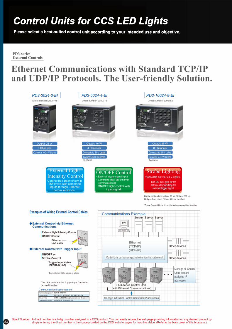
83
Ethernet Communications with Standard TCP/IP and UDP/IP Protocols. The User-friendly Solution.
Strobe lighting time: 40 µs, 80 µs, 120 µs, 200 µs,
600 µs, 1 ms, 4 ms, 10 ms, 20 ms, or 40 ms
*These Control Units do not include an overdrive function.
PD3-5024-4-EI PD3-10024-8-EIPD3-3024-3-EI
Output: 28 W
3 Channels
Connects to 24-V Lights
Output: 46 W
4 Channels
Connects to 24-V Lights
Connects to HLV2 Series(Spotlights)
Output: 95 W
8 Channels
Connects to 24-V Lights
Connects to HLV2 Series(Spotlights)
Communications Example
Other devices
Other devices
PD3-series Control Unit
(with Ethernet Communications)
Manage individual Control Units with IP addresses
PC
Server Server Server
Ethernet
(TCP/IP)
(UDP/IP)
Manage all Control
Units that are
assigned IP
addresses.
Control Units can be managed individual from the host network.
Examples of Wiring External Control Cables
Communications protocol
Standards
Baud rate
Transmission medium
TCP/IP UDP/IP
IEEE802.3, IEEE802.3u, IEEE802.3x
10 Mbps/100 Mbps (Automatically detected.)
10BASE-T, 100BASE-TX
Communications Specifications
* The LAN cable and the Trigger Input Cable can
be used together.
External Light Intensity Control
ON/OFF Control
Trigger Input Cable
(EXCB2-M10-3)
Ethernet
LAN cable
*External Control Cables are sold as options.
External Control via Ethernet Communications
ON/OFF or
Strobe Control
External Control with Trigger Input
Direct number: 2000776 Direct number: 2000779 Direct number: 2000782
External Light Intensity Control
Strobe LightingON/OFF Control
Control the light intensity in 256 levels with command inputs through Ethernet
communications.
• External trigger signal input
• Command input via Ethernet
communications Turn ON the Lights for the set time after inputting the
external trigger signal. ON/OFF light control with
input signal.
*Applicable only for 24 V Lights.
PD3-series External Controls
Direct Number : A direct number is a 7-digit number assigned to a CCS product. You can easily access the web page providing information on any desired product by simply entering the direct number in the space provided on the CCS website pages for machine vision. (Refer to the back cover of this brochure.)

84
Specifications of Control Unit with EIA-485 Communications
Light intensity setting
ON/OFF setting
Lighting mode setting
Error detection output
External control connector
Command sent when overcurrent output is detected.
External trigger input or command input via EIA-485 communications
Manual
External
Manual
External
Set to any of 256 levels on front-panel setting switch.
Command input via EIA-485 communications
Trigger input
Lighting intensity/lighting mode setting
MIL connector, 10 pins
e-CON connector, 3 pins
Set to any of 11 levels on front-panel setting switch.
Command input via EIA-485 communications
Specifications of Control Unit with Parallel Communications
Light intensity setting
ON/OFF setting
Lighting mode setting
Error detection output
External control connector
Set to any of 256 levels on front-panel setting switch.
8-bit input (B0 to B7), write pulse (BRTWR), and channel selection (CHSEL0 to CHSEL2)
Trigger input
Lighting intensity/lighting mode setting
MIL connector, 10 pins
MIL connector, 20 pins
NPN transistor output between pins 19 (OC) and 20 (OE) of external control connector
Normal: Open, Overcurrent output detected: Closed
Manual
External
External trigger input
Manual
External
Set to any of 11 levels on front-panel setting switch.
4-bit input (M0 to M3), write pulse (TRGWR), and channel selection (CHSEL0 to CHSEL2)
Specifications of Control Unit with Ethernet Communications
External trigger input or command input via TCP/IP or UDP/IP communications
Light intensity setting
ON/OFF setting
Lighting mode setting
Error detection output
External control connector
Command sent when overcurrent output is detected.
Manual
External
Manual
External
Set to any of 256 levels on front-panel setting switch.
Command input via TCP/IP or UDP/IP communications
Trigger input
Lighting intensity/lighting mode setting
MIL connector, 10 pins
RJ-45 connector
Set to any of 11 levels on front-panel setting switch.
Command input via TCP/IP or UDP/IP communications
PD3-3024-3 Common Specifications
*Do not intentionally short-circuit the positive and negative output terminals.
Lighting method
Drive method
Light intensity control method
Number of channels
Applicable Lights (rated)
PWM frequency
Error detection display
Overcurrent protection*
Input voltage (rated)
Power consumption (typ.)
Frequency
Output voltage (rated)
Output current (rated)
Operating temperature and humidity
Storage temperature and humidity
Cooling method
CE Marking
Material and surface processing
Weight
Accessories
Constant lighting/strobe lighting
Constant-voltage system
PWM control and lighting time control
3 channels
24-VDC input, Total for all channels: 28 W
125 kHz
Front-panel digital OCP display
Operates at 107% of rated output current or higher. Reset by pressing operation setting switch for at least 1 second or by cycling the power supply.
100 to 240 VAC
78 VA
50/60 Hz
24 VDC
Total for 3 channels: 1.1 A
Temperature: 0 to 40°C, Humidity: 20% to 85% RH (with no condensation)
Temperature: !20 to 60°C, Humidity: 20% to 85% RH (with no condensation)
Natural air cooling
Safety standard: Conforms to EN 61010-1, EMC standard: Conforms to EN 61326, Class A.
Materials: Aluminum and resin, Surface processing: Blue alumite
600 g max.
2-m long power cord with 3-prong connector (with ground terminal)
PD3-5024-4 Common Specifications
*Do not intentionally short-circuit the positive and negative output terminals.
Lighting method
Drive method
Light intensity control method
Number of channels
Applicable Lights (rated)
PWM frequency
Error detection display
Overcurrent protection
Input voltage (rated)
Power consumption (typ.)
Frequency
Output voltage (rated)
Output current (rated)
Operating temperature and humidity
Storage temperature and humidity
Cooling method
CE Marking
Material and surface processing
Weight
Accessories
Constant lighting/strobe lighting
24V LIGHT connectors: Constant-voltage system, HLV LIGHT connectors: Constant-current system
24V LIGHT connectors: PWM control and lighting time control, HLV LIGHT connectors: Variable-current control
4 channels
24V LIGHT connectors: Lights with 24-VDC input, HLV LIGHT connectors: HLV2/HLV-series Spotlights, Total for 4 channels: 46 W
125 kHz
Front-panel digital OCP display: Overcurrent error, EFN display: Fan Stop Error, and EID display: ID error (HLV2/HLV-series Spotlights only)
Operates at 107% of rated output current or higher. Reset by pressing operation setting switch for at least 1 second or by cycling the power supply.
100 to 240 VAC
70 VA
50/60 Hz
24 VDC
Total for 4 channels: 1.91 A
Temperature: 0 to 40°C, Humidity: 20% to 85% RH (with no condensation)
Temperature: !20 to 60°C, Humidity: 20% to 85% RH (with no condensation)
Forced air cooling
Safety standard: Conforms to EN 61010-1, EMC standard: Conforms to EN 61326, Class A.
Materials: Aluminum and resin, Surface processing: Blue alumite
1,200 g max.
2-m long power cord with 3-prong connector (with ground terminal)*Strobe lighting is possible only with 24-V Lights. (These Control Units do not include an overdrive function.)*HLV LIGHT: Strobe lighting is not possible for HLV2-series Spotlights.The HLV-14-R/-SW/-BL/GR and HLV-27-series Spotlights cannot be connected.
PD3-10024-8 Common Specifications
*Do not intentionally short-circuit the positive and negative output terminals.
Lighting method
Drive method
Light intensity control method
Number of channels
Applicable Lights (rated)
PWM frequency
Error detection display
Overcurrent protection
Input voltage (rated)
Power consumption (typ.)
Frequency
Output voltage (rated)
Output current (rated)
Operating temperature and humidity
Storage temperature and humidity
Cooling method
CE Marking
Material and surface processing
Weight
Accessories
Constant lighting/strobe lighting
24V LIGHT connectors: Constant-voltage system, HLV LIGHT connectors: Constant-current system
24V LIGHT connectors: PWM control and lighting time control, HLV LIGHT connectors: Variable-current control
8 channels
24V LIGHT connectors: Lights with 24-VDC input, HLV LIGHT connectors: HLV2/HLV-series Spotlights, Total for 8 channels: 95 W (High-output Light connector: 95 W (1 connector))
125 kHz
Front-panel digital OCP display: Overcurrent error, EFN display: Fan Stop Error, and EID display: ID error (HLV2/HLV-series Spotlights only)
Operates at 107% of rated output current or higher. Reset by pressing operation setting switch for at least 1 second or by cycling the power supply.
100 to 240 VAC
130 VA
50/60 Hz
24 VDC
Total for 8 channels: 3.95 A
Temperature: 0 to 40°C, Humidity: 20% to 85% RH (with no condensation)
Temperature: !20 to 60°C, Humidity: 20% to 85% RH (with no condensation)
Forced air cooling
Safety standard: Conforms to EN 61010-1, EMC standard: Conforms to EN 61326, Class A.
Materials: Aluminum and resin, Surface processing: Blue alumite
1,500 g max.
2-m long power cord with 3-prong connector (with ground terminal)*Strobe lighting is possible only with 24-V Lights. (These Control Units do not include an overdrive function.)*HLV LIGHT: Strobe lighting is not possible for HLV2-series Spotlights. The HLV-14-R/-SW/-BL/GR and HLV-27-series Spotlights cannot be connected.
If you register as a CCS member, you can download all materials (such as PDF or DXF drawings and operation manuals) from our website. You can also request us to select the appropriate Light Unit, borrowing demonstration units and to quote the product’s price. Please go ahead and register as a member today. (Refer to back cover of this brochure.)

85
Dimension Diagrams (Unit: mm)
PD3-5024-4 Control Units
Control Unit with
Parallel Communications
197
120
(6)
(1.8
)
Setting indicators
Channel selection switch
External control connector
Digital display Setting switch
Channel indicators
Manual/external mode selector
Trigger logic switch
External trigger input connector AC inlet
Output connectors
(for HLV Spotlights)
Output connectors
(For 24-V Lights)
Functional ground terminal
(6)
14
169
10 59.3
(6) Rubber foot
82.6 (13) (8)
Control Unit with
Ethernet Communications
Control Unit with
EIA-485 Communications
External control reset switch
(Resets network settings.)
*The Control Unit with EIA-485 or Ethernet Communications has the same dimensions as the Control Unit with Parallel Communications.
External control connector
ID switch
External control connector
DIN rail mounting bracket
PD3-3024-3 Control Units
Control Unit with
Parallel Communications
*The Control Unit with EIA-485 or Ethernet Communications has the same dimensions as the Control Unit with Parallel Communications.
Control Unit with
Ethernet Communications
External control connector
External control reset switch
(Resets network settings.) Control Unit with
EIA-485 Communications
External control connector
ID switch
Output connectors
Setting indicators
Channel selection switch
AC inlet
External control connector
Setting switch
Channel indicators
Digital display
Trigger logic switch
External trigger input connector
Manual/external mode selector
12
0
12
4
84
(6)
(1.8
)
56
Four, M3 screws
(Insertion depth of 5 mm max.)
14
59.310
(6)
(6)
82.6 (8)(13)
DIN rail mounting bracket
PD3-10024-8 Control Units
Control Unit with
Parallel Communications
82.6(13) (8)
(6)
(1.8
)
Setting indicators
Channel selection switch
External control connector
Digital display Setting switch
Channel indicators
Manual/external mode selector
Trigger logic switch
External trigger input connector AC inlet
Output connectors
(for HLV Spotlights)
Output connectors
(For 24-V Lights)
Functional ground terminal
220
120
(6)
10 59.3
Rubber foot
192
14
(6)
Control Unit with
Ethernet Communications
Control Unit with
EIA-485 Communications
*The Control Unit with EIA-485 or Ethernet Communications has the same dimensions as the Control Unit with Parallel Communications.
External control connectorExternal control connector
ID switch
External control reset switch
(Resets network settings.)
DIN rail mounting bracket
Direct Number : A direct number is a 7-digit number assigned to a CCS product. You can easily access the web page providing information on any desired product by simply entering the direct number in the space provided on the CCS website pages for machine vision. (Refer to the back cover of this brochure.)
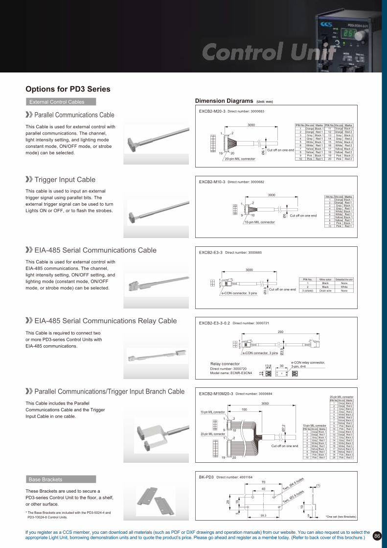
86
Options for PD3 Series
External Control Cables
Parallel Communications Cable
This Cable is used for external control with
parallel communications. The channel,
light intensity setting, and lighting mode
constant mode, ON/OFF mode, or strobe
mode) can be selected.
EXCB2-M20-3
20-pin MIL connector
3000
Ø6
.1
2 1
20 19
1 2
19 20 Cut off on one end
PIN No. Wire color Marks
1 Orange Black 1
2 Orange Red 1
3 Gray Black 1
4 Gray Red 1
5 White Black 1
6 White Red 1
7 Yellow Black 1
8 Yellow Red 1
9 Pink Black 1
10 Pink Red 1
PIN No. Wire color Marks
11 Orange Black 2
12 Orange Red 2
13 Gray Black 2
14 Gray Red 2
15 White Black 2
16 White Red 2
17 Yellow Black 2
18 Yellow Red 2
19 Pink Black 2
20 Pink Red 2
Dimension Diagrams (Unit: mm)
Trigger Input Cable
This cable is used to input an external
trigger signal using parallel bits. The
external trigger signal can be used to turn
Lights ON or OFF, or to flash the strobes.
10-pin MIL connector
3000
Ø5
1 2
9 10
1 2
9 10
Cut off on one end
PIN No. Wire color Marks1 Orange Black 12 Orange Red 13 Gray Black 14 Gray Red 15 White Black 16 White Red 17 Yellow Black 18 Yellow Red 19 Pink Black 1
10 Pink Red 1
EIA-485 Serial Communications Cable
This Cable is used for external control with
EIA-485 communications. The channel,
light intensity setting, ON/OFF setting, and
lighting mode (constant mode, ON/OFF
mode, or strobe mode) can be selected.e-CON connector, 3 pins
3000
Ø3
.9
1 2 3
1 2 3
Cut off on one end
PIN No. Wire color Embedded line color
1 Black None
2 Black White
3 (shield) NoneDrain wire
This Cable includes the Parallel
Communications Cable and the Trigger
Input Cable in one cable.
Parallel Communications/Trigger Input Branch Cable
3000
100
Ø7
.2
2 1
9 10
10-pin MIL connector
2 1
19 20
20-pin MIL connector
1 2
19 20
1 2
9 10
Cut off on one end
PIN No. Wire color Marks
1 Orange Black 2
2 Orange Red 2
3 Gray Black 2
4 Gray Red 2
5 White Black 2
6 White Red 2
7 Yellow Black 2
8 Yellow Red 2
9 Pink Black 2
10 Pink Red 2
11 Orange Black 3
12 Orange Red 3
13 Gray Black 3
14 Gray Red 3
15 White Black 3
16 White Red 3
17 Yellow Black 3
18 Yellow Red 3
19 Pink Black 3
20 Pink Red 3
20-pin MIL connector
PIN No. Wire color Marks
1 Orange Black 1
2 Orange Red 1
3 Gray Black 1
4 Gray Red 1
5 White Black 1
6 White Red 1
7 Yellow Black 1
8 Yellow Red 1
9 Pink Black 1
10 Pink Red 1
10-pin MIL connector
70
Two, Ø3.5 holes
Two, Ø4.5 holes
59.3
29
40
19
5
(1)
5
10
*One set (two Brackets)
These Brackets are used to secure a
PD3-series Control Unit to the floor, a shelf,
or other surface.
* The Base Brackets are included with the PD3-5024-4 and
PD3-10024-8 Control Units.
Base Brackets
e-CON connector, 3 pins
1 2 3
1 2 3
Ø3
.9
200
3013.8
13
e-CON relay connector,
3-pin, 4!4Direct number: 3000720
Model name: ECNR-E3CN4
Relay connector
EIA-485 Serial Communications Relay Cable
This Cable is required to connect two
or more PD3-series Control Units with
EIA-485 communications.
If you register as a CCS member, you can download all materials (such as PDF or DXF drawings and operation manuals) from our website. You can also request us to select the appropriate Light Unit, borrowing demonstration units and to quote the product’s price. Please go ahead and register as a member today. (Refer to back cover of this brochure.)
Direct number: 3000683
EXCB2-M10-3 Direct number: 3000682
EXCB2-E3-3 Direct number: 3000685
EXCB2-E3-3-0.2 Direct number: 3000721
EXCB2-M10M20-3 Direct number: 3000684
BK-PD3 Direct number: 4001164

PD2 Series
Offers repeatable, linear light intensity control with
256 discrete levels using course and fine adjustments
Digital Control Units
The PD2 Series of digital power supplies are designed specifically for use with CCS LED lights. Compared with analog power
supplies, the PD2 Series provides a more linear and repeatable intensity control because of the force-detent adjustment course/fine
adjustment knobs and benefits of pulse duty control. The PD2 Series is suitable for all CCS lights without dedicated power supplies.
The Series is designed to meet the requirements of the widest variety of applications with the 12 and 24V options, power ratings
range, and the number of independent output channels.
87
PD2-3012 / PD2-3024 / PD2-5012 / PD2-5024 / PD2-3012-2 /
PD2-3024-2 / PD2-3012-4 / PD2-3024-4 / PD2-3012-8 / PD2-3024-8
Models with CE Marking:
PD2-1012 / PD2-1024 PD2-3012 / PD2-3024 PD2-5012 / PD2-5024 PD2-3012-2 / PD2-3024-2 PD2-3012-4 / PD2-3024-4 PD2-3012-8 / PD2-3024-8
Specifications
1) Operating voltage: 85 to 132VAC or 85 to 264VAC, 2) At a voltage of 100VAC
Model
Direct Number
Input voltage
Input current
Frequency
Inrush current
Number of channels
DC output voltage
Output power
Intensity control
External control input
External control connector
ON/OFF control
ON/OFF response
Startup time
Output overcurrent protection
Operating environment
Storage environment
Weight
PD2-1012
1
12V
9.5W max.
PD2-1024
1
24V
9.0W max.
PD2-3012
1
12V
28W max.
PD2-3024
1
24V
28W max.
PD2-5012
1
12V
46W max.
PD2-5024
1
24V
46W max.
PD2-3012-2
2
12V
28W max.
PD2-3024-2
2
24V
28W max.
PD2-3012-4
4
12V
27W max.
PD2-3024-4
4
24V
27W max.
PD2-3012-8
8
12V
25W max.
PD2-3024-8
8
24V
25W max.
50 / 60Hz
15A typ.
100 to 240V AC
0.78A typ.0.25A typ. 0.78A typ.1.3A typ.
100 to 120V AC
: 60kHz (approx.) pulse duty control
: 256-level of intensity control using dual 16 position Coarse and Fine rotary knob on the control panel
: Intensity control using 8-bit parallel signal
Control method
Manual
External control
: At + 5.0V with 4.7k Pull-up resistor.
: Ø3.5-mm microphone jack
: D-Sub 15-pin ON signal (Asynchronous with write sequence)
Input circuit
Manual
External control
Input circuit
Manual /
External control
HS-CMOS, Low level: 1.35V or less, High level: 3.15V or more
OFF - ON: 10!s typ., ON - OFF: 10!s typ.
0.5sec typ.
Activated by 107% minimum of the rated output current and reset by turning the power supply ON with front panel power switch.
Temperature 0 to 40°C, humidity 20 to 85%RH (with no condensation)
Temperature -20 to 60°C, humidity 20 to 85%RH (with no condensation)
: At + 5.0V with 1.5k Pull-up resistor.
D-Sub 25-pin (plug)D-Sub 15-pin (plug)
: D-Sub 25-pin OFF signal
(Asynchronous with write sequence)
0.7kg or less 1.1kg or less 1.1kg or less1.3kg or less 1.2kg or less 1.5kg or less
1)
2)
2)
2000519 2000520 2000521 2000522 2000536 2000537 2000523 2000524 2000525 2000526 2000527 2000528
Selecting a PD2 Series control unit
(1) Select a12-V or 24-V output models according to the voltage of a LED lights used.
(2) Select from the 10-watt or 30-watt models according to the total of power consumption of LED lights to be used.
(3) Select from 2-channel, 4-channel, or 8-channel models to according to the number of independent outputs needed
(multiple lights can be connected to a single output channel with a 2 or 4 way split cables.
(4) Select one of the optional external control cables. (Refer to information on page 88)
Direct Number : A direct number is a 7-digit number assigned to a CCS product. You can easily access the web page providing information on any desired product by simply entering the direct number in the space provided on the CCS website pages for machine vision. (Refer to the back cover of this brochure.)
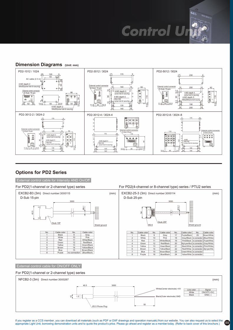
External control cable for ON/OFF ONLY
NFCB2-3 (3m)
10
40.5 3000
Ø3.5 Phone Plug50
White(Center electrode) +5V
Black(Outer electrode) GND
(mm)
For PD2(1-channel or 2-channel type) series
External control cable for Intensity AND On/Off
Options for PD2 Series
EXCB2-25-3 (3m)EXCB2-B3 (3m) (mm)(mm)
For PD2(1-channel or 2-channel type) series For PD2(4-channel or 8-channel type) series / PTU2 series
40.5
Dsub 15P
3000
Shield ground
Ø8.1
54
Dsub 25P
M2.6
3000
Ø10.1
Shield ground
D-Sub 15-pin D-Sub 25-pin
88
Dimension Diagrams (Unit: mm)
PD2-3012 / 3024
PD2-3012-2 / 3024-2 PD2-3012-4 / 3024-4 PD2-3012-8 / 3024-8
PD2-1012 / 1024
Power
Coarse
Fine
L1 L2
1
2
L1
L1
(FAN)
L2
Error
4-M3 depth 5
(screw hole for securing)
External control connector
D-Sub 15-pin
4-M3 depth 5
40x140(screw hole for securing)
15 140 15
140 1515
11.5 40 10.5 20 130 20
10
90
10
5.5
110
62
(7) 170 9
PD2-3012-2
On/Off Light
External Control
100-240V~
50/60Hz 78VA
External control connector
D-Sub 25-pin
85x140(screw hole for securing)
20 130 2012.5 85 12.5
5.5
122
110
15 140 15
4-M3
9 170 (8)
PD2-3012-8
4-M3 depth 5
4-M3 depth 5(screw hole for securing)
15 140 15
140 1515
20 130 20
10
90
10
(7) 170 9
L1
L2
L1
(FAN)
External control connector
D-Sub 15-pin
11.5 40 10.5
External
Control
100-240V~
50/60Hz 78VA
On/Off Light
Power
Coarse
Fine
L1
Error
5.5
11
0
62
PD2-3012
40x140(screw hole for securing)
80
5.5
110
20 130 20 12.5 85 12.5
4-M3 depth 5
15 140 15
9 170 (8)
External control connector
D-Sub 25-pin
L1 L2 L3 L4
External Control 100-240V~50/60Hz 78VA
L1 L2 L3 L4
Ext ModeError
Coarse
Fine
PD2-3012-4
Power
85x140(screw hole for securing)
PD2-5012 / 5024
(7) 230 9
20 190 20
15 200 15
15 200 15
10
.79
09
.3
4-M3 depth 5
40x200(screw hole for securing)
4-M3 depth 5(screw hole for securing)
(FAN)
Light
L2
L1
L1
11.5 40 10.5
External control connector
D-Sub 15-pin
1
Power
Coarse
Fine
L
Error
PD2-5024
62
11
05
.513.59313.5
9120(8)
13.593
16
54
16
12 62 12
On/Off
Light
FG
External Control
100-120V
50/60Hz 27VA
External control connectorD-Sub 15-pin
54x93(screw hole for securing)
AC cable (2.3 m)
4-M3 depth 2
ErrorPower
PD2-1024
54
5.516 54 16
86
Coarse Fine
54x93(screw hole for securing)
4-M3 depth 2
No. Cable color No. Cable color
9
10
11
12
13
14
15
no connection
Black
White
Red
Green
Yellow
Brown
Blue
Purple
Gray
Pink
White/Black
Red/Black
Green/Black
Yellow/Black
Brown/Black
(Blue/Black)
1
2
3
4
5
6
7
8
No. Cable color No. Cable color
1
2
3
4
5
6
7
8
9
10
11
12
13
14
15
16
Black
White
Red
Green
Yellow
Brown
Blue
Purple
Gray
Pink
White/Black
Red/Black
Green/Black
Yellow/Black
Brown/Black
Blue/Black
No. Cable color No. Cable color
17
18
19
20
21
22
23
24
25
no connection
no connection
no connection
no connection
no connection
no connection
no connection
Purple/Black
Gray/Black
Pink/Black
Blight green/Black
Black/White
Red/White
Green/White
Yellow/White
Brown/White
(Blue/White)
(Purple/White)
(Gray/White)
(Pink/White)
(Blight green/White)
Line color Signal
ON/OFF(+5V)
GND(-)
White
Black
If you register as a CCS member, you can download all materials (such as PDF or DXF drawings and operation manuals) from our website. You can also request us to select the appropriate Light Unit, borrowing demonstration units and to quote the product’s price. Please go ahead and register as a member today. (Refer to back cover of this brochure.)
Direct number:3000115
Direct number:3000267
Direct number:3000114

PSB3-30024Analog Control Units with High Capacity of 300 WThe PSB3-30024 is a high-capacity (300 W) Analog Control Unit.Light Unit output is provided for one channel/four connectors (two metal connectors and two EL connectors). Light intensity can be set to any of 256 levels, even though the PSB3-30024 is an Analog Control Unit.Equipped for parallel, serial, or analog control all in a single Unit. Setting the light intensity has been optimized via the intensity range switch to select the optimal output for your Light Units.
2,300 gWeight:
110
mm
245 mm
97 mm
ON/OFF input connector
Parallel communications connector
ID switch
Set up to 4 Units.
EIA-485 communications/analog input connector
Parallel communicationsEIA-485 communications(serial)Analog input
Control mode Description
Command input for 256 levels of intensity via EIA-485 communications.
Command input via EIA-485 communications
Control the intensity to 256 levels via an analog voltage (0 to 5 V).
Control the intensity to 256 levels via parallel signal inputs.
Light intensity control
ON/OFF control
Light intensity control
Light intensity control
ON/OFF control is possible in combination with parallel, serial, or analog control.
ON/OFF control via OFF signal input (parallel bit method).ON/OFF control
18 to 24 V
15 to 24 V
12 to 24 V
Output voltageIntensity range selector
Digital display
Quick operation through a pushbutton dial
Setting switch
• Intensity setting to any of 256 levels• Turn ON the power supply while pressing the button for external control mode.• Push and hold for two seconds to lock the intensity value.
Press to select. Hold to lock. Turn to adjust.
Select the intensity range that best suits the Light Unit.
Supports the reproducibility of intensity values through a digital display.
Optimal Intensity Settings through Minimum Intensity Value Switching
Parallel, Serial, and Analog Control in a Single Unit
* Output characteristics depend on the Light Unit.
* This graph is for illustration only.(Level)
(Level)0 64 128 192 255Intensity setting
0 1.25 2.5 3.75 5Intensity setting via analog input
12
15
18
24
12 to 24 VIntensity range
18 to 24 VIntensity range
15 to 24 VIntensity range
Out
put v
olta
ge
(V)
ON/OFF input connector
Analog Control Units
89Direct Number : A direct number is a 7-digit number assigned to a CCS product. You can easily access the web page providing information on any desired product by
simply entering the direct number in the space provided on the CCS website pages for machine vision. (Refer to the back cover of this brochure.)

External Control Cables(Unit: mm)These cables are used for parallel communications, EIA-485 communications, and the analog input. Select the right cable for the required control method.
Manual
Lighting control
EIA-485 communications settings
Lighting delay (typ.)Error detection displayError detection output
Parallel communications
Error is output and light output is stopped for internal AC/DC error.External control connector
0.1 s“Err” displayed on front-panel digital display
Set via the front ID switch (terminating resistance is ON only when the ID is 00).
Lighting signal (OFF)
Command input via EIA-485 communications
Command input via EIA-485 communications
Serial communications
Parallel bit input
ID
Terminating resistance
Set via the front ID switch (00 to 03). Maximum of 4 connected Units.
Analog input
Set any of 256 levels via the setting switch. Press and hold the switch for 2 seconds to lock the intensity value.8-bit intensity value setting (B0 to B7) and write signal (WR)
ModelDirect numberLighting methodDrive methodLight intensity control methodNumber of channelsApplicable Light Unit ratingLight intensity control
PSB3-300242000762Constant lightingConstant-voltage systemVariable-voltage control1 channel24 V 300 WManual and external intensity control
External control mode can be selected by pushing the setting switch while turning ON the power to the Control Unit.Analog voltage (0 to 5 V)
External
Error output terminal (0C, 0E), photocoupler insulation, open-collector output, alarm open (load current of less than 10 mA), and error status (serial communications)
Variable output voltage rangeFront manual/external switch (MODE)Select between 3 ranges via the front intensity range selector (RANGE).
Overcurrent protectionOvervoltage protectionRated input voltagePower consumption (typ.)FrequencyInrush current (typ.)Ground leakage currentOutput voltage variation range (typ.)
Operating temperature and humidity
Storage temperature and humidity
Vibration resistanceCooling methodCE MarkingEnvironmental regulationsMaterial, coating, and surface processing
WeightAccessories
RoHS compliantSteel plate, thickness of cover: 1.0, thickness of chassis: 1.6, N3 leather tone finish2,300 g max.2-meter long 3-prong power cord with ground terminal (1)
Temperature: 0 to 40°C, Humidity: 20% to 85%RH (with no condensation)Temperature: −20 to 60°C, Humidity: 20% to 85%RH (with no condensation)Acceleration: 19.6 m/s2, frequency: 10 to 55 Hz, cycles: 3 minutes, sweep cycle: for 1 hour each in X, Y, and Z directionsForced air coolingConforms to safety standard EN 61010-1.
Operation is restored automatically at 105% of the rated current.Operation is restored when the power is turned ON again at 120% to 155% of the rated current.100-240 VAC410 VA50/60 Hz20 A/40 A (primary/secondary value at 100 VAC), 40 A/40 A (primary/secondary value at 240 VAC)3.5 mA max. (264 V AC, 60 Hz, with no load)Select between 3 ranges via the front intensity range selector.12 to 24 V
*With no load.*With no load.*With no load.
15 to 24 V18 to 24 V
* From a cold start
Conforms to EMC standard EN 61326-1, Class A.
Four, M3 bottom mounting screws (Insertion depth of 5 mm max.)
17.5
7 196 7
16
65
PSB3-30024
INTENSITY
EXTERNAL
HIGHMIDDLE
ID
97
Parallel communications connector
ON/OFF input connector
Analog input and EIA-485 communications connector
ID switch
Digital display
Setting switch(Pushbutton dial)
Manual/external mode selector
Intensity range selector
110
Front
POWER
L1-1
L1-3
L1-4
L1-2
Output connector(EL connector)
Output connector(Metal connector)
Fan exhaust outlets
Power switch
AC inlet
245
Fan air inlets
Fan exhaust outlets
Side View
Bottom viewRear view
EXCB2-M20-3 EXCB2-M10-3 EXCB2-M10M20-3 EXCB2-E6AN-3
EXCB2-E6SR-3 EXCB2-E6SR-E3-3 EXCB2-E3-3This cable is used to connect two or more Control Units together.
20-pole MIL connector
3000
Ø6.
1
21
2019
1 2
19 20 Loose wires on one end
10-pole MIL connector
3000
Ø5
1 2
9 10
1 2
9 10 Loose wires on one end
3000
100
Ø7.
2
21
9 10
10-pole MIL connector
21
19 20
20-pole MIL connector
1 2
19 20
1 2
9 10
Loose wires on one end
Ø3.
9
123
3000
This cable is used to connect to an external device when connecting two or more Control Units together.
Loose wires on one end
Loose wires on one end
3000
Ø4.
6
123456
Loose wires on one endØ
4.6
3000
123456
Ø3.
9
123
200
(Relay connector to Relay connector)
123456
3000
(Unit to relay connector)321
EXCB2-E3-E3-0.2
ECNR-E3CN43013.8
13
e-CON relay connector3 pins, 4×4
Common Specifications Dimension Diagrams (Unit: mm)
Options
Parallel Communications Cable ON/OFF Input Cable Parallel Communications and ON/OFF Input Branch Cable Analog Input Cable
EIA-485 Communications Relay CableEIA-485 Communications Relay CableEIA-485 Communications Cable
Serial communications
90If you register as a CCS member, you can download all materials (such as PDF or DXF drawings and operation manuals) from our website. You can also request us to select the appropriate Light Unit, borrowing demonstration units and to quote the product’s price. Please go ahead and register as a member today. (Refer to back cover of this brochure.)
Direct number: 3000683 Direct number: 3000682 Direct number: 3000684 Direct number: 3000687
Direct number: 3000686 Direct number: 3000717
Direct number: 3000721
Direct number: 3000720
Direct number: 3000685
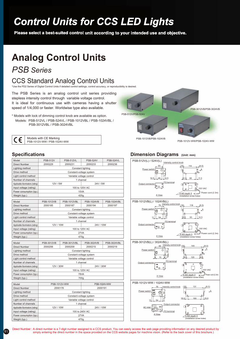
91
PSB-512V/PSB-524V
PSB-3012VB/PSB-3024VB
PSB-1012VB/PSB-1024VBPSB-1012V-WW/PSB-1024V-WW
Models with CE MarkingPSB-1012V-WW / PSB-1024V-WW
Model
Direct Number
Lighting method
Drive method
Light control method
Number of channels
Applicable illuminators (rating)
Input voltage (rating)
Power consumption (typ.)
Weight (typ.)
Constant lighting
Constant-voltage system
Variable voltage control
1 channel
12V / 5W 24V / 5W
100 to 120V AC
15VA
420g
PSB-524V PSB-524VLPSB-512VLPSB-512V
2000233 200023620002312000229
Model
Direct Number
Lighting method
Drive method
Light control method
Number of channels
Applicable illuminators (rating)
Input voltage (rating)
Power consumption (typ.)
Weight (typ.)
Constant lighting
Constant-voltage system
Variable voltage control
1 channel
12V / 10W 24V / 10W
100 to 120V AC
27VA
470g
PSB-1024VB PSB-1024VBLPSB-1012VBLPSB-1012VB
2000194 200019720001872000185
Model
Direct Number
Lighting method
Drive method
Light control method
Number of channels
Applicable illuminators (rating)
Input voltage (rating)
Power consumption (typ.)
Weight (typ.)
Constant lighting
Constant-voltage system
Variable voltage control
1 channel
12V / 30W 24V / 30W
100 to 120V AC
78VA
700g
PSB-3024VB PSB-3024VBLPSB-3012VBLPSB-3012VB
2000215 200021920002092000206
Model
Direct Number
Lighting method
Drive method
Light control method
Number of channels
Applicable illuminators (rating)
Input voltage (rating)
Power consumption (typ.)
Weight (typ.)
Constant lighting
Constant-voltage system
Variable voltage control
1 channel
12V / 10W 24V / 10W
100 to 240V AC
27VA
470g
PSB-1024V-WW
2000191
PSB-1012V-WW
2000178
Specifications Dimension Diagrams (Unit: mm)
PSB-512V(L) / 524V(L)
PSB-1012VB(L) / 1024VB(L)
PSB-1012V-WW / 1024V-WW
PSB-3012VB(L) / 3024VB(L)Intensity control knob
Power switch
8 70 8
86
55
5
(16) 149 (8.5)
14.5 120 14.5
A
Output connectorFG terminal
100 VAC
4-M3 depth 5
(installation screw holes)
Power cord (2.3m)
4-M3 depth 5
(installation screw holes)
Power cord (2.3m)
100 VAC
11 1154
76
45
5
Intensity control knob
Power switch
118 (8.5)(16)
10.5 93 14.5
A
FG terminal
Output connector
A View
A View
4-M3 depth 5
(installation screw holes)
100 VAC
Power cord (2.3m)
A View
FG terminalOutput connector
22.5 80 11.5
114 (8.5)(16)
A
65
12.5 40 12.5
42
5
Power switch
Intensity control knob
The PSB Series is an analog control unit series providing
stepless intensity control through variable voltage control.
It is ideal for continuous use with cameras having a shutter
speed of 1/4,000 or faster. Worldwise type also available.
* Models with lock of dimming control knob are available as option.
Models: PSB-512VL / PSB-524VL / PSB-1012VBL / PSB-1024VBL /
PSB-3012VBL / PSB-3024VBL
PSB Series
CCS Standard Analog Control Units
Analog Control Units
*Use the PD2 Series of Digital Control Units if detailed control settings, control accuracy, or reproducibility is desired.
INTENSITY
12
34
109
87
5 6
76
50
5
11 54 11
POWER
Intensity control knob
Power switch
LIGHT
GND
50/60Hz 27VA 100-240V
Output connector
FG terminal
A View
AC inlet
(16) 131 (8.5)
15.5 100 15.5
A
4-M3 depth 5
(installation screw holes)
Direct Number : A direct number is a 7-digit number assigned to a CCS product. You can easily access the web page providing information on any desired product by simply entering the direct number in the space provided on the CCS website pages for machine vision. (Refer to the back cover of this brochure.)
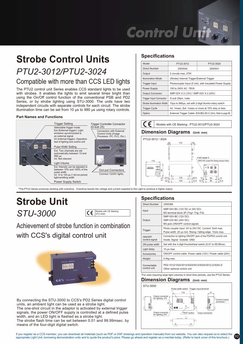
92If you register as a CCS member, you can download all materials (such as PDF or DXF drawings and operation manuals) from our website. You can also request us to select the appropriate Light Unit, borrowing demonstration units and to quote the product’s price. Please go ahead and register as a member today. (Refer to back cover of this brochure.)
*The PTU2 Series produces strobing with overdrive. Overdrive boosts the voltage and current supplied to the Light to produce a higher output.
Direct Number
PTU2-3012/PTU2-3024
Compatible with more than CCS LED lights
Strobe Control Units
Part Names and Functions
The PTU2 control unit Series enables CCS standard lights to be used with strobes. It enables the lights to emit several times bright than using the On/Off control function of the conventional PSB and PD2 Series, or by strobe lighting using STU-3000. The units have two independent circuits with separate controls for each circuit. The strobe illumination time can be set from 10 !s to 990 !s using rotary controls.
Specifications
Model
Trigger Setting
Selectable trigger mode.Ext (External trigger): Light emission synchronized to an external signalInt (Internal trigger): Operation test of lighting and control unit
Ext: Intensity can be adjusted to between 10% and 100% of the pulse widthInt: 10 to 100 µs (1.42-ms period) light-emitting width
Pulse Width Setting
Ext: Two channels are set automatically between 10 and 990 µsInt: Not relevant
Light Volume
Power Supply Switch
Out put Connectors
Connect 12/24V lights.
Trigger Controller Connector (D-sub 25)
Connection with External Control Units (Image Processor, PC, PLC, Etc.)
Output
Illumination Mode
Trigger Input
Power Supply
Output Connector
Trigger Input Connector
Strobe illumination Width
Trigger Cycle
Option
2 circuits max, 27W
(Strobe) Internal Trigger/External Trigger
Photocoupler Input (5 mA), with Insulated Power Supply
100 to 240V AC 78VA
SMP-02V X 2 (12V) / SMP-03V X 2 (24V)
D-sub 25pin, male
10!s to 990!s, set with 2-digit thumb-rotary switch
Int: 1msec, Ext: 1msec or more at 10% duty or less
External Trigger Cable: EXCB2-25-3 (3m)
Models with CE Marking : PTU2-3012/PTU2-3024
PTU2-3012 / 3024
Dimension Diagrams (Unit: mm)
Strobe Unit
By connecting the STU-3000 to CCS's PD2 Series digital control units, an ambient light can be used as a strobe light. The one-shot circuit in the adaptor is activated by external trigger signals, the power ON/OFF supply is controlled at a defined pulse width, and an LED light is flashed as a strobe light. The strobe flash time can be set between 0.01 and 99.99msec. by means of the four-digit digital switch.
STU-3000
Specifications
Achievement of strobe function in combination
with CCS's digital control unit
Models with CE Marking
STU-3000
Dimension Diagrams (Unit: mm)
*For uses requiring large light volumes in short time periods, use the PTU2 Series.
Direct Number 2000366
PD2-1012/1024/3012/3024/5012/5024/3012-2/3024-2/
Other optional control unit
Input
Output
Trigger
ON/OFFcontrol signal
ON pulse width
Light delay
Accessories
Weight
Connectable control unit
SMP-04V-BC (12V DC or 24V DC)
M3 terminal block 3P (Trig+ Trig- FG)
SMP-02V-BC (12V DC)
SMP-03V-BC (24V DC)
M3 jack (ON/OFF control signal)
Photo-coupler input 5V to 24V DC Current: 5mA max.
Pulse width: 20 !s min. Rising / falling edge: 10 s max.
Connection to lighting ON/OFF jack of the PD/PD2 control unit
Inside: Signal Outside: GND
Set with the 4-digit thumbwheel switch (0.01 to 99.99ms).
10 !s max.
ON/OFF control cable Power cable (12V) / Power cable (24V)
0.4kg max.
STU-3000
msec
PULSE WIDTH
Pulse width switch Trigger input terminal
Input connectorTEST button
TESTSTU-3000
TRIGGER
FG
+_
70
110 31
Output connectorfor lighting 12V
Output connectorfor lighting 24V
Control outputconnector
Refer to page 88.
PTU2-3012
2000540
PTU2-3024
2000541
1 1 1 1
External Control
100-240V AC50/60Hz 78VA
15
(18)170(8)
90
5.5
110
4-M3 depth 5
85X145 (used for fixing screw hole)
80 15
12.5 85 12.512.5 145 12.5
22.5 125 22.5
Control(%)
Ext
Int
TriggerL1 L2
Pulse WidthL1
L2
20 10
30
40
50 6070
80
90
100 20 10
30
40
50 6070
80
90
100
PTU2-3012
Error
Power

93
Compact and Efficient
PB-2430
This single compact control unit handles 12V and 24V CCS LED
lights at the same time, and allows the user to control the light
intensity of each one simultaneously or separately. It operates with
24VDC voltage input, and is DIN rail mountable.
Models with CE Marking
PB-2430
Part Names and Functions
Output connector for 12V LED lights
Output connector for 24V LED lights
Intensity control for 12V LED lights Intensity control for 24V LED lights
24VDC input terminals
Dimension Diagrams (Unit: mm)
Cost-effective, easy-to-use strobe control unit with overdriving power output
Overdriving capability provides CCS 12V standard lights with 2-3 times
brighter output
High performance allows synchronization of light and camera
Rugged, compact housing
For use with 24VDC input
DIN rail mountable
SpecificationsDirect Number
Input
DC output
Output voltage range/
Light intensity control
Input terminal
Output Connector
Over-current protection
Insulation
Cooling method
Weight
24VDC 10%, 50W max (36W typ.)
L1: 12VDC 2A 24W max.,
L2: 22VDC 1.1A 24W max.
Total power consumption must not exceed 30W max.
L1: Approx, 8.3 to 12.0VDC
L2: Approx. 15.0 to 22.0VDC
Intensity control by the 'ADJUST' potentiometers
Two terminals with 7.62 mm pitch, M3 screw
L1: SMP-02V-BC [JST] 1: Output + 2: Output -
L2: SMP-03V-BC [JST] 1. Output + 2: NC 3:Output -
Built-in input Polyswitch
Non-insulation between input and output
Natural air-cooling
Approx. 300g
Note: 1)When input voltage decreases, the output L2 will also decrease
(Input voltage must be 1.5V or higher than output voltage).
2000018
High Performanceand Low PricePS-3012-D24
Strobe Control Unit
Models with CE Marking
PS-3012-D24
PS-3012-D24
Dimension Diagrams (Unit: mm)
Specifications
Input
Output
DrivableIlluminators
Input terminal
Output Connector
Lighting Method
Pulse Width
Trigger Interval
Trigger Input
Delay Time
24VDC 10% 20W minimum (average)
Strobe output, 18VDC, 8A max.(The peak value of using 30W of load.)
12V/30W max.
7 terminals with 7.62mm pitch, M3 screw
SMP-02V-BC [JST] (Pin 1: + Pin 2: -)
Strobe with overdriving (Built-in Protection Circuit)
10.0!s to 1.0ms (Pulse width control by potentiometer)
12.5ms min, (The trigger interval to the next signal should
be more than 12.5ms, otherwise the signal will be ignored.)
Photo-coupler input, Input current 5mA or more, Over 20!s
pulse width, Rise/Fall time 10!s max.
Max. 10!s (Trigger input-Strobing)
Direct Number 2000157
Direct Number : A direct number is a 7-digit number assigned to a CCS product. You can easily access the web page providing information on any desired product by simply entering the direct number in the space provided on the CCS website pages for machine vision. (Refer to the back cover of this brochure.)

94
CC-ST-1024
A Compact, Lightweight
Controller for LED Light
Compact Controller
The CC-ST-1024 is a special LED Illumination Controller that is
the size of a sensor amplifier. It mounts to DIN rail. It can be
installed inside a control panel, alongside the sensor amplifiers
inside a device, and in various other locations. The 24-V DC
power input is suited for worksites.
Control the LED Light with Three Lighting Modes
In this mode, the light is
l i t c o n s t a n t l y . T h e
intensity of the light can
be set to any of 100
levels.
Constant Lighting Mode
In this mode, lighting is
synchronized with the
high signal f rom the
i m a g e p r o c e s s i n g
device.
ON/OFF Mode
In th is mode, st robe
lighting is synchronized
with the trigger signal
f r o m t h e i m a g e
processing device. The
lighting time can be set.
Strobe Mode
Dimension Diagrams (Unit: mm)
16
9.4
5.7
15
.8
32
.5
70
75
(1000)
(2000)
2.5
(50)(13)
LED Light cable
External signal cable connector
24-VDC input cable
(3150)
(50)(13)1: White(Input +)
2: Black(Input -)
1 2
Housing: BPHD-002T-0.5 (JST)
Contacts: PAP-02V-K (JST)
This cable is for external signal.
Use it to input external signal
into the Controller.
External Signal Cable (3 m)
Option: NFCB2-CC-3 Dimension Diagrams (Unit: mm)
Install next to the camera or near the Light for compact installation.
Install in control box for central control with other devices.
Installation Inside Equipment:
Install in large-scale equipment.
Specifications
Product name
Model
Direct number
Drive method
Light control method
Applicable Light Units(rating)
PWM frequency
Input overcurrent protection
Input voltage
Power consumption(typ.)
Output voltage(rating)
Output current(rating)
Vibration resistance
Impact resistance
Cooling method
CE marking
Storage environment
Operating environment (indoors only)
Compact Controller for LED Light (Strobe Light Type)
CC-ST-1024
2000654
Constant-voltage system
PWM control, lighting time control
24 V, 10 W
100 kHz
Acceleration: 19.6 m/s2, frequency: 10 to 55 Hz,
cycles: 3 minutes, for 1 hour each in X, Y, and Z directions
Acceleration: 49.0 m/s2, operation time: 30 ms,
number of times: 3 times each in 6 directions
Natural air cooling
Conforms to EMC standard EN 61326, Class A.
RoHS compliant
ABS
80 g
Flat-blade screwdriver
A fuse cuts the circuit to protect the Controller from overcurrent.
Temperature: 0 to 40°C, Humidity: 20% to 85%RH (no condensation)
Temperature: -20 to 60°C, Humidity: 20% to 85%RH (no condensation)
24 VDC ±10%
11.0 W (10-W LED Light Unit at maximum light intensity)
24 VDC
0.42 A
Environmental regulations
Materials
Weight
Accessories
Install in small-scale equipment or stand-alone devices.
Note: These application examples are only conceptual.
Actual application will depend on the installation environment.
A 2-meter 24-V DC input cable is included.
A 1-meter LED illumination cable is included.
Direct number:3000569
If you register as a CCS member, you can download all materials (such as PDF or DXF drawings and operation manuals) from our website. You can also request us to select the appropriate Light Unit, borrowing demonstration units and to quote the product’s price. Please go ahead and register as a member today. (Refer to back cover of this brochure.)
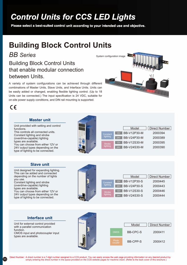
Unit provided with setting and control functions.This controls all connected units.Constant lighting and strobe (overdrive-capable) lightingtypes are available.You can choose from either 12V or24V output types depending on thetype of lighting to be connected.
Master unit
Unit designed for expanding lighting.This can be added and connecteddepending on the number of lightsyou use.Constant lighting and strobe (overdrive-capable) lightingtypes are available.You can choose from either 12V or24V output types depending on thetype of lighting to be connected.
Slave unit
Unit for external control providedwith a parallel communicationfunction.CMOS input and photocoupler input types are available.
Interface unit
Direct NumberModel
Constantlighting
Strobelighting
12V BB-V12P30-M
BB-V12S30-M
BB-V24P30-M24V
12V
24V BB-V24S30-M
2000394
2000395
2000389
2000390
Direct NumberModel
Constantlighting
Strobelighting
2000445
2000446
2000443
2000444
12V BB-V12P30-S
BB-V12S30-S
BB-V24P30-S24V
12V
24V BB-V24S30-S
Direct NumberModel
Photocoupler
CMOS
2000412
2000411BB-CPC-S
BB-CPP-S
95
BB Series
Building Block Control Units
that enable modular connection
between Units.
Building Block Control Units
A variety of system configurations can be achieved through different
combinations of Master Units, Slave Units, and Interface Units. Units can
be easily added or changed, enabling flexible lighting control. (Up to 18
Units can be connected.) The input specification is 24 VDC, suitable for
on-site power supply conditions, and DIN rail mounting is supported.
System configuration image
Direct Number : A direct number is a 7-digit number assigned to a CCS product. You can easily access the web page providing information on any desired product by simply entering the direct number in the space provided on the CCS website pages for machine vision. (Refer to the back cover of this brochure.)
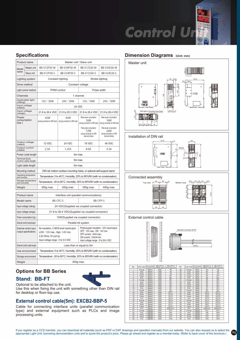
96
Dimension Diagrams (Unit: mm)
Installation of DIN rail
Connected assembly
Master unit
External control cable
(5000)
Half pitch connector 50 Pin
25242322212019181716151413121110987654321
50494847464544434241403938373635343332313029282726
Interface unit (parallel communications)
24 VDC(Supplied via coupled connector)
21.6 to 26.4 VDC(Supplied via coupled connector)
10W(Supplied via coupled connector)
Parallel bit system
No insulation, C-MOS level input/output
LOW : 1.5V max., High : 3.5V min.
2.2k Ohms, 5V pull-up
Input voltage range : 0 to 5.5 VDC
Photocoupler insulation : 24V input/output
OFF : 10V max., ON : 14V min.
OFF current : 4mA max.,
ON current : 5.8mA min.
Input voltage range : 0 to 26.4 VDC
Less than or equal to 5m
Temperature: 0 to 40°C, Humidity: 20% to 85%RH (with no condensation)
Temperature: -20 to 60°C, Humidity: 20% to 85%RH (with no condensation)
300g max.
Product name
Model name
Input voltage (rating)
Input voltage (range)
Power consumption (typ.)
External control input/output
External control input
/output specifications
External control cable length
Use environment
Storage environment
Weight
Specifications
Options for BB Series
Master unit / Slave unit
Constant voltage
1 channel
5m max.
5m max.
5m max.
DIN rail, bottom surface mounting holes, or optional self-support stand
Temperature: 0 to 40°C, Humidity: 20% to 85%RH (with no condensation)
Temperature: -20 to 60°C, Humidity: 20% to 85%RH (with no condensation)
350g max. 350g max. 350g max. 400g max.
(during connection to 30W load) (during connection to 30W load)(during connection to 30W load)
Mean power consumption:
(during connection to 30Wload and strobe)
Peak power consumption:
(during connection to 30Wload and strobe)
Peak power consumption:
(during connection to 30W load)
Mean power consumption:
Constant lighting
PWM control
21.6 to 26.4 VDC 21.6 to 25.3 VDC 21.6 to 26.4 VDC
24 VDC
12 VDC 24 VDC 18 VDC 48 VDC
21.6 to 26.4 VDC
Strobe lighting
Pulse width
Product name
Lighting system
Drive method
Light control method
Channels
Powerconsumption(typ.)
Modelname
Applicable light (rating)
Input voltage(rated)
Input voltage(range)
Output voltage(rated)
Output current(rated)
Terminal block control cable length
Operating temperatureand humidity
Storage temperatureand humidity
Power code length
Light cable length
Mounting method
Weight
Master unit
Slave unit
628.1
3.5 34.5
22.7
52.6
115.540
148
12.5
BBV12P30-M
26.5 26.5 26.5 36
6.5
27
3-M3 depth 4 (mounting screw holes)
No. Line colorColor and segmentsof broken line
BB-CPC-S(CMOS input)
Black1
Black1
Black1
Black1
Black1
Black2
Black2
Black2
Black2
Black2
Black3
Black3
Black3
Black3
Black3
Black4
Black4
Black4
Black4
Black4Continuous
black lineContinuous
black lineContinuous
black lineContinuous
black lineContinuous
black line
Orange
Gray
White
Yellow
Pink
Orange
Gray
White
Yellow
Pink
Orange
Gray
White
Yellow
Pink
Orange
Gray
White
Yellow
Pink
Orange
Gray
White
Yellow
Pink
GND
GND
GND
GND
GND
GND
GND
GND
GND
GND
GND
GND
GND
GND
GND
GND
GND
GND
GND
GND
GND
GND
GND
GND
GND
NC
NC
NC
B7–
B6–
B5–
B4–
B3–
B2–
B1–
B0–
OFF7–
OFF6–
OFF5–
OFF4–
OFF3–
OFF2–
OFF1–
OFF0–
ERROUT–
EXT–
WR–
CS2–
CS1–
CS0–
No. Line colorColor and segmentsof broken line
BB-CPC-S(CMOS input)
26
27
28
29
30
31
32
33
34
35
36
37
38
39
40
41
42
43
44
45
46
47
48
49
50
Red1
Red1
Red1
Red1
Red1
Red2
Red2
Red2
Red2
Red2
Red3
Red3
Red3
Red3
Red3
Red4
Red4
Red4
Red4
Red4Continuous
red lineContinuous
red lineContinuous
red lineContinuous
red lineContinuous
red line
Orange
Gray
White
Yellow
Pink
Orange
Gray
White
Yellow
Pink
Orange
Gray
White
Yellow
Pink
Orange
Gray
White
Yellow
Pink
Orange
Gray
White
Yellow
Pink
NC
NC
NC
B7
B6
B5
B4
B3
B2
B1
B0
OFF7
OFF6
OFF5
OFF4
OFF3
OFF2
OFF1
OFF0
ERROUT
EXT
WR
CS2
CS1
CS0
BB-CPP-S(Photocoupler input)
NC
NC
NC
B7+
B6+
B5+
B4+
B3+
B2+
B1+
B0+
OFF7+
OFF6v
OFF5+
OFF4+
OFF3+
OFF2+
OFF1+
OFF0+
ERROUT+
EXT+
WR+
CS2+
CS1+
CS0+
1
2
3
4
5
6
7
8
9
10
11
12
13
14
15
16
17
18
19
20
21
22
23
24
25
BB-CPP-S(Photocoupler input)
Stand: BB-FTOptional to be attached to the unit.Use this when fixing the unit with something other than DIN rail for desktop or floor-top use.
External control cable(5m): EXCB2-BBP-5Cable for connecting interface units (parallel communication type) and external equipment such as PLCs and image processing units.
4115.5
76
72
148
40
DIN rail
40 40 4 6.5
26.6
26.5
25.5
27 27 6.5
115.5
13
40 40
Top view Bottom view
If you register as a CCS member, you can download all materials (such as PDF or DXF drawings and operation manuals) from our website. You can also request us to select the appropriate Light Unit, borrowing demonstration units and to quote the product’s price. Please go ahead and register as a member today. (Refer to back cover of this brochure.)
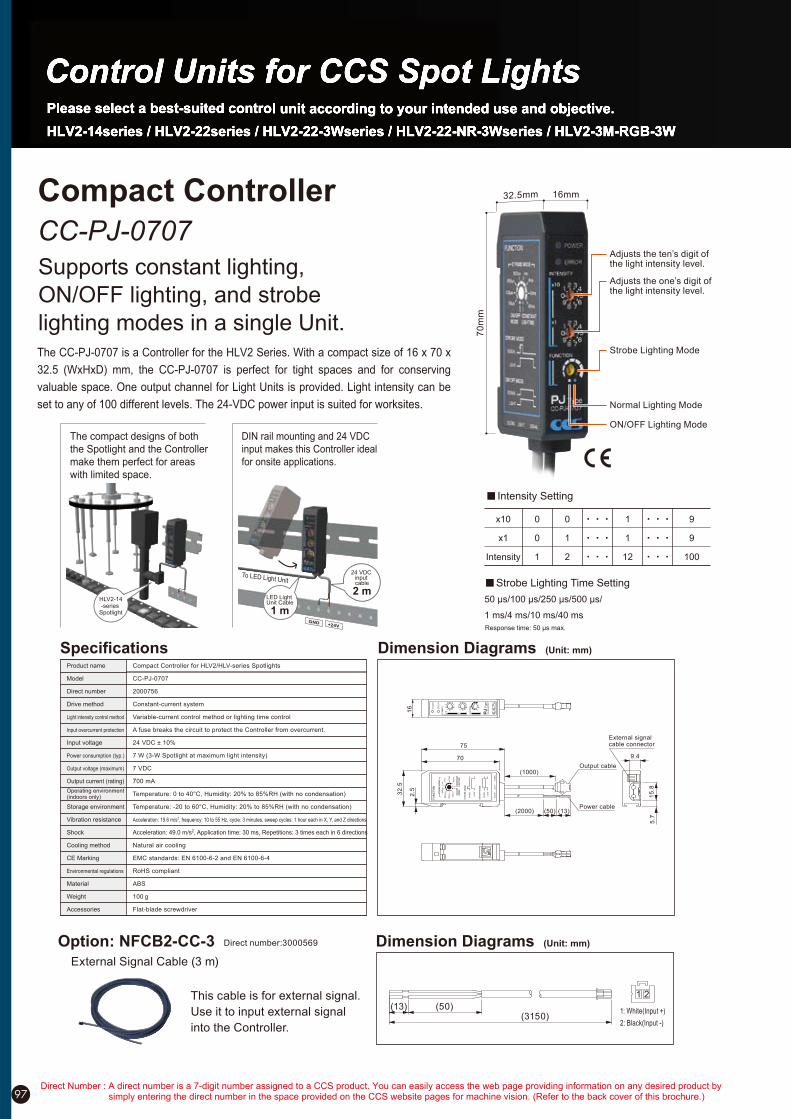
97
CC-PJ-0707
Supports constant lighting,
ON/OFF lighting, and strobe
lighting modes in a single Unit.
Compact Controller
The CC-PJ-0707 is a Controller for the HLV2 Series. With a compact size of 16 x 70 x
32.5 (WxHxD) mm, the CC-PJ-0707 is perfect for tight spaces and for conserving
valuable space. One output channel for Light Units is provided. Light intensity can be
set to any of 100 different levels. The 24-VDC power input is suited for worksites.
DIN rail mounting and 24 VDC
input makes this Controller ideal
for onsite applications.
To LED Light Unit
24 VDC input cable
2 mLED Light Unit Cable
1 mGND +24V
The compact designs of both
the Spotlight and the Controller
make them perfect for areas
with limited space.
HLV2-14-series
Spotlight
Adjusts the ten’s digit of the light intensity level.
Adjusts the one’s digit of the light intensity level.
Normal Lighting Mode
ON/OFF Lighting Mode
Strobe Lighting Mode
32.5mm
70
mm
16mm
Specifications Dimension Diagrams (Unit: mm)
16
32
.5
70
75
(1000)
(2000)
2.5
(50) (13)Power cable
Output cable
9.4
5.7
15
.8
External signal cable connector
Option: NFCB2-CC-3 Dimension Diagrams (Unit: mm)
(3150)(50)(13)
1: White(Input +)
2: Black(Input -)
1 2
External Signal Cable (3 m)
This cable is for external signal.
Use it to input external signal
into the Controller.
Direct number:3000569
50 !s/100 !s/250 !s/500 !s/
1 ms/4 ms/10 ms/40 ms
x10 0 0 1 9
x1 0 1 1 9
Intensity 1 2 12 100
Response time: 50 !s max.
Intensity Setting
Strobe Lighting Time Setting
Product name
Model
Direct number
Drive method
Light intensity control method
Input overcurrent protection
Input voltage
Power consumption (typ.)
Output voltage (maximum)
Output current (rating)
Operating environment (indoors only)
Storage environment
Vibration resistance
Shock
Cooling method
CE Marking
Environmental regulations
Material
Weight
Accessories
Compact Controller for HLV2/HLV-series Spotlights
CC-PJ-0707
2000756
Constant-current system
Variable-current control method or lighting time control
A fuse breaks the circuit to protect the Controller from overcurrent.
24 VDC ± 10%
7 W (3-W Spotlight at maximum light intensity)
7 VDC
700 mA
Temperature: 0 to 40°C, Humidity: 20% to 85%RH (with no condensation)
Temperature: -20 to 60°C, Humidity: 20% to 85%RH (with no condensation)
Acceleration: 19.6 m/s2, frequency: 10 to 55 Hz, cycle: 3 minutes, sweep cycles: 1 hour each in X, Y, and Z directions
Acceleration: 49.0 m/s2, Application time: 30 ms, Repetitions: 3 times each in 6 directions
Natural air cooling
EMC standards: EN 6100-6-2 and EN 6100-6-4
RoHS compliant
ABS
100 g
Flat-blade screwdriver
Direct Number : A direct number is a 7-digit number assigned to a CCS product. You can easily access the web page providing information on any desired product by simply entering the direct number in the space provided on the CCS website pages for machine vision. (Refer to the back cover of this brochure.)

98
PJ Series
Four Models for your Working Environment.
Analog Control Units
The PJ Series consists of Analog Control Units for the HLV2 Series. They provide stepless intensity control for a variable current.
Models are available with 2 or 3 output channels for Light Units. You can also select between AC and DC for the power source.
40.5
Dsub 15P
3000
Shield ground
Ø8.1
100 to 240V AC
24V DC
PJ-1505-2CA PJ-1505-3CA PJ-1505-2CD24 PJ-1505-3CD24
Options for PJ Series (mm)
External control cable
Direct number:3000569
Model:EXCB2-B3(3m)
2-channel 3-channel 2-channel 3-channel
Specifications
Dimension Diagrams (Unit: mm)
PJ-1505-2CA The PJ-1505-3CA is also the same size. PJ-1505-2CD24 The PJ-1505-3CD24 is also the same size.
75
38
(8)
A
42.5 55
820
DIN rail bracket
A View120
37.5
37.5
(installation screw holes)
11 11
2-M3 depth 3
L1 L2
Remote
Manual
Remote ControlIntensity
Hi
Lo
Control
DC24V IN
Range
PJ-1505-2CD24
142
L1 L2
L1 Range switchIntensity volume
Indicator lamp
Remote control connector
Remote/Manual switch
Output connector Power input terminals
5
0 10
5
0 101
2
34 6
7
8
9 1
2
34 6
9
7
8
L2
ControlRangeRemoteHi
Lo Manual
5
Intensity
Power
L1
62
16 54 (16)
PJ-1505-2CA
Remote/Manual switch
Intensity volume
Power switchL1 Range switch
Indicator lamp
1210812132
A
4-M3 installation screw holes (Bottom)
16
54
(16)
86
16100(16)
Remote control connectorAC inlet
Remote Control
Output
L1L2
FG
Ground screw Output connector
A View
PJ-1505-2CA
2000131
27VA typ.
2
PJ-1505-3CA
2000136
37VA typ.
3
PJ-1505-2CD24
2000134
10W typ.
2
PJ-1505-3CD24
2000139
14.5W typ.
3
Manual: Front light intensity dial
Remote (external): Analog input voltage of 0 to 5 V (5.25 V maximum)
380g
Model
Direct number
Input voltage(rated)
Input voltage(range)
Power consumption
Number of channels
Output voltage(maximum rated)
Light intensity control
ON/OFF control
External control connector
Weight(max.) 640g 660g
100 to 240 VAC
85 to 264 VAC
24 VDC
10 to 24 VDC
5.5 VDC
OFF: 2.5 to 5.0 V (24 V maximum) ON: 0.8 to 0 V (pulled down with 4.7 K!)
D-Sub, 15-pin (plug)
Models with CE Marking
PJ-1505-2CA / PJ-1505-3CA /
PJ-1505-2CD24 / PJ-1505-3CD24
If you register as a CCS member, you can download all materials (such as PDF or DXF drawings and operation manuals) from our website. You can also request us to select the appropriate Light Unit, borrowing demonstration units and to quote the product’s price. Please go ahead and register as a member today. (Refer to back cover of this brochure.)
No. Cable color No. Cable color
9
10
11
12
13
14
15
no connection
Black
White
Red
Green
Yellow
Brown
Blue
Purple
Gray
Pink
White/Black
Red/Black
Green/Black
Yellow/Black
Brown/Black
(Blue/Black)
1
2
3
4
5
6
7
8
100-240V

Mounted in front of a lens, R60 blocks light of 600nm or less, and R64 light of 640nm or less, and both transmit approximately 85% of light in wavelength bands longer than these.
Sharp Cut Filters
Blocks ambient light out of red wavelength range
R60 Series R64 Series
Filter
Mounted on front lens thread to transmit approximately 47% of in a wavelength band centered on 440nm in the wavelength range from 350 to 520 nm.
Blue-light Filters
Blocks ambient light out of blue wavelength range
V44 Series
99
R60-C
R60-16
R60-25
R60-27
R60-30
R60-40
R60-46
4000658
4000657
4000609
4000489
4000490
4000491
4000659
For C-mount
M16.0 P0.5
M25.5 P0.5
M27.0 P0.5
M30.5 P0.5
M40.5 P0.5
M46.0 P0.75
Model Name NotesDirect number
R64-C
R64-16
R64-25
R64-27
R64-30
R64-40
R64-46
For C-mount
M16.0 P0.5
M25.5 P0.5
M27.0 P0.5
M30.5 P0.5
M40.5 P0.5
M46.0 P0.75
4000508
4000493
4000494
4000495
4000496
4000498
4000500
Model Name NotesDirect number
V44-C
V44-25
V44-27
V44-30
V44-40
V44-46
For C-mount
M25.5 P0.5
M27.0 P0.5
M30.5 P0.5
M40.5 P0.5
M46.0 P0.75
Model Name Notes
4000539
4000534
4000535
4000536
4000537
4000538
Direct number
Filter
Screw the polarizing filter onto the front of the camera lens. The filter eliminates reflections and glare from the surface in combination with the polarizer.
Prevents glare from the light
Polarizing Filters
PL Series
Prevents glare from the light
Polarizer
PL Series
Polarization Plate
PL-LFV2-35
PL-LFV2-50
PL-LFV2-70
PL-LFV2-100
PL-LFV2-130
PL-LFV2-200
Model Name
4000458
4000459
4000460
4000455
4000456
4000457
Direct number
PL-LDR-32
PL-LDR-42
PL-LDR-50
PL-LDR2-70
PL-LDR-90
PL-LDR-120-40
PL-SQR-56
*
Model Name
4000428
4000430
4000432
4000623
4000441
4000424
4000465
Direct number
*PL-LDR2-70 comes with an adaptor for installation.
Attach the polarizer to lights. It eliminates reflections and glare in combination with the polarizing filter.
Prevents glare from the light
Polarizer
PL Series
Polarization Plate
PL-LDL2-33!8-HO
PL-LDL2-33!8-VE
PL-LDL2-41!16
PL-LDL2-80!16
PL-LDL2-119!16
PL-LDL2-74!30
PL-LDL2-146!30
PL-LDL2-218!30
PL-LDL2-266!30
PL-LDL2-41!16-VE
PL-LDL2-80!16-VE
PL-LDL2-119!16-VE
Model Name
4001028
4001029
4000847
4000848
4000849
4000850
Direct number Model Name
4000854
4000851
4000853
4000888
4000889
4000890
Direct number
PL-LDL2-74!30-VE
PL-LDL2-146!30-VE
PL-LDL2-218!30-VE
PL-LDL2-266!30-VE
Model Name
4000891
4000892
4000893
4000894
Direct number
For the LDL2 Series
Mounting with Emission from Four Directions
Black Not black
Differentiating Paired Polarizing Plates
Paired Polarizing Plates will turn
black when theyoverlap in opposite
directions and will not beblack when
they overlap in the same direction.
Example
The polarization direction differs by 90°.
PL-LDL2-41X16-VE
PL-LDL2-41X16
(PL-LDL2-33X8-HO)
(PL-LDL2-33X8-VE)
Use a combination of
two pairs of the two
types.
There are two types of Polarizing Plates for the LDL2-33!8 and LDL2 Series.
They are used together as shown below.
Square type
For the LFV2 Series
For the LDL2-33!8 Series
PL-25
PL-25-NL
PL-27
PL-27-NL
PL-30
PL-30-NL
M25.5 P0.5
M25.5 P0.5 (With lock)
M27.0 P0.5
M27.0 P0.5 (With lock)
M30.5 P0.5
M30.5 P0.5 (With lock)
Model Name Notes
4000370
4000372
4000374
4000376
4000377
4000379
Direct number
PL-40
PL-40-NL
PL-46
M40.5 P0.5
M40.5 P0.5 (With lock)
M46.0 P0.75
Model Name Notes
4000383
4000384
4000388
Direct number
Ring type Square type
Optional PartsOptional Parts
CautionHeat may cause deformation or discoloring depending on the operation environment. Make sure that countermeasures against overheating are implemented and that the temperature does not exceed the operating limit.
(Longpass filter) (Bandpass filter)
Direct Number : A direct number is a 7-digit number assigned to a CCS product. You can easily access the web page providing information on any desired product by simply entering the direct number in the space provided on the CCS website pages for machine vision. (Refer to the back cover of this brochure.)

100
Light Control Film
Light Control Films
Converts diffused light into parallel light
LC Series
Mounted to back lights to suppress light diffraction for visual inspections, enabling sharp imaging of profiles.
Plastic film arrayed with fine louvers suppresses the diffusion of light in specific directions and improves parallelism.
LC-TH-27!27-HO
LC-TH-43!35-HO
LC-TH-51!51-HO
LC-TH-63!60-HO
LC-TH-83!75-HO
LC-TH-100!100-HO
Model Name
4001043
4001044
4001045
4000943
4000944
4000945
Direct number
LC-TH-140!105-HO
LC-TH-160!120-HO
LC-TH-200!150-HO
LC-TH-224!170-HO
LC-TH-211!200-HO
Model Name
4000946
4000947
4000948
4000949
4000950
Direct number
LC-TH-27!27-VE
LC-TH-43!35-VE
LC-TH-51!51-VE
LC-TH-63!60-VE
LC-TH-83!75-VE
LC-TH-100!100-VE
Model Name
4001046
4001047
4001048
4001003
4001004
4001005
Direct number
LC-TH-140!105-VE
LC-TH-160!120-VE
LC-TH-200!150-VE
LC-TH-224!170-VE
LC-TH-211!200-VE
Model Name
4001006
4001007
4001008
4001009
4001010
Direct number
LC-LFL-100
LC-LFL-180
LC-LFL-200
Model Name
4000300
4000301
4000302
Direct number
By mounting this on a co-axial light, the parallelism of light is improved and the particularities of a workpiece can be effectively imaged.
LC-LFV2-35
LC-LFV2-50
LC-LFV2-70
LC-LFV2-100
LC-LFV2-130
LC-LFV2-200
Model Name
4000315
4000316
4000317
4000312
4000313
4000314
Direct number
The TH Series offers a selection for louver direction: longitudinal or transverse.
HO VE
Louver Orientation
Lo
uve
r Orie
nta
tion
Using Polarizing Filters and Polarizing Plates
The Polar iz ing Fi l ters and
Polar izing Plates are used
together. Regular reflective
components are cut out and
the effects can be observed
when the polarizing direction of
the polarizing plate installed on
t h e L i g h t U n i t a n d t h e
polarizing direction of the filter
attached to the camera are at a
right angle (90°) to each other.
Install the Polarizing Plate on the light-emitting side of the Light Unit.
Attach the Polarizing Filter to the tip of the camera lens.
Rotate the Polarizing Filter so that the angle of polarization is a right angle (90°) in relat ion to the Polarizing Plate.
Application Instructions
Attaches to many different lights to reduce shine from glossy applications.
Prevents shine and glare
Diffuser
Diffusion Plate
DF Series
Ring type
DF-LDL2-33!8
DF-LDL2-41!16
DF-LDL2-80!16
DF-LDL2-119!16
DF-LDL2-74!30
DF-LDL2-146!30
DF-LDL2-218!30
DF-LDL2-266!30
Model Name
4001026
4000840
4000841
4000842
4000843
Direct number Model Name
4000844
4000845
4000846
Direct number
DF-LDR-32
DF-LDR-42
DF-LDR-50
DF-LDR-70
DF-LDR-90
DF-LDR-120-45
DF-SQR-56
DF-LDR-48LA
DF-LDR-74LA
DF-LDR-100LA
DF-LDR-132LA
DF-LDR-170LA
DF-LDR-208LA
Model Name
4000140
4000143
4000147
4000156
4000164
4000125
4000201
Direct number Model Name
4000146
4000160
4000123
4000129
4000134
4000138
Direct number
CV-LDL2-41!16
CV-LDL2-80!16
CV-LDL2-119!16
CV-LDL2-74!30
CV-LDL2-146!30
CV-LDL2-218!30
CV-LDL2-266!30
Model Name
4000860
4000861
4000862
4000863
4000864
4000865
4000866
Direct number
Protective Plate
Protects the emission section
Protector
CV Series
The plate protects the emission section of the Light Unit.Note: The Protective Plate is not intended to provide
protection against dust or water droplets.
For the LDL2 Series
For the LDL2 Series
Square type
For the LDL2-33!8 Series
Low-angle type
No Polarizing Plate With a Polarizing Plate Sharp-cut Filter Application Example
When you want to view a workpiece
as a silhouette, contrast cannot be
made with only a red backlight via
ambient light (due to indoor lighting
or other factors). However, you can
use a sharp-cut fi lter to cut out
ambient light and allow only the red
light to pass through. This allows
you to capture a clear contrast of
the shape of the workpiece.
HO:The direction of louvers is horizontal when installing LC film on the TH series as shown on the right-hand side.
VE:The direction of louvers is vertical when installingLC flim on the TH series as shown on the right-hand side.
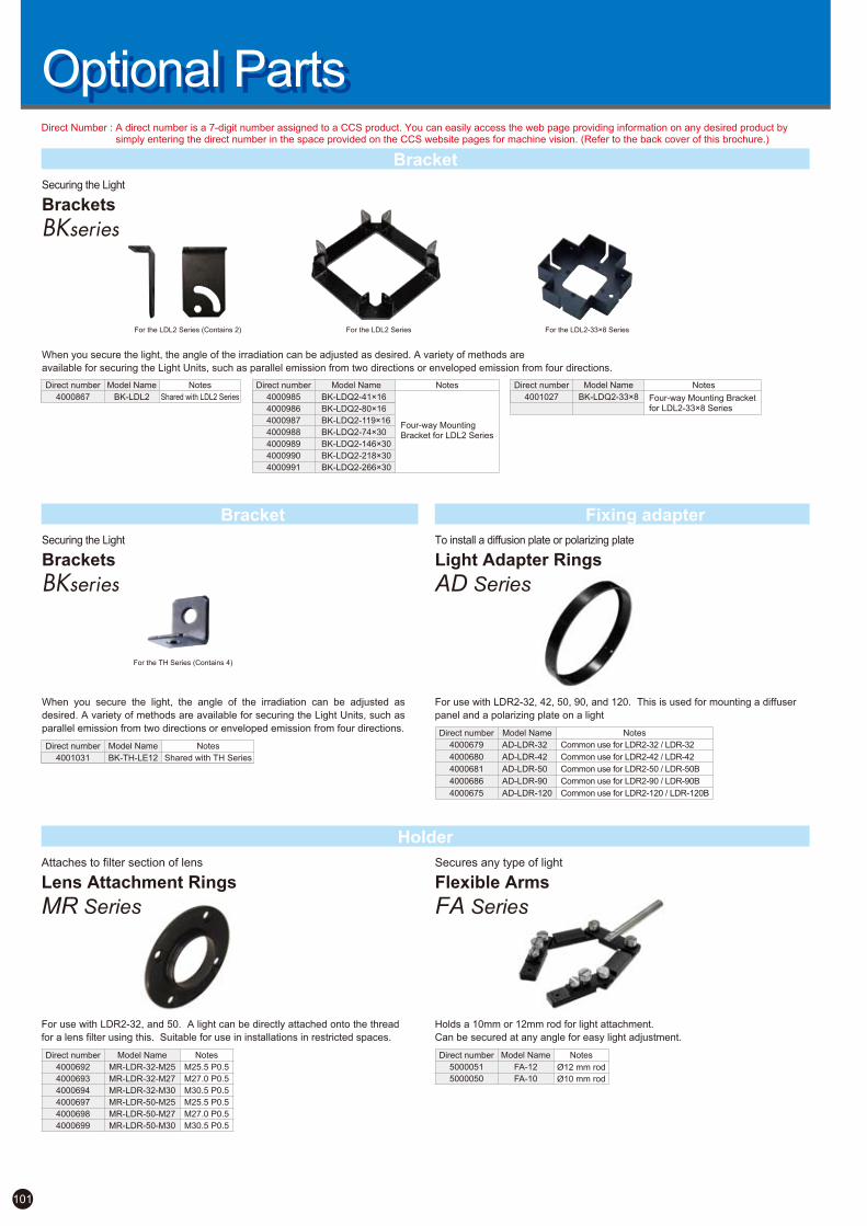
For the LDL2 Series
101
Bracket
Holder
BK-LDQ2-41!16
BK-LDQ2-80!16
BK-LDQ2-119!16
BK-LDQ2-74!30
BK-LDQ2-146!30
BK-LDQ2-218!30
BK-LDQ2-266!30
Model Name
Four-way Mounting Bracket for LDL2 Series
Notes
4000985
4000986
4000987
4000988
4000989
4000990
4000991
Direct number
BK-LDQ2-33!8
Model Name
Four-way Mounting Bracketfor LDL2-33!8 Series
Notes
4001027
Direct number
Fixing adapter
For use with LDR2-32, 42, 50, 90, and 120. This is used for mounting a diffuser
panel and a polarizing plate on a light
To install a diffusion plate or polarizing plate
Light Adapter Rings
AD Series
AD-LDR-32
AD-LDR-42
AD-LDR-50
AD-LDR-90
AD-LDR-120
Model Name
Common use for LDR2-32 / LDR-32
Common use for LDR2-42 / LDR-42
Common use for LDR2-50 / LDR-50B
Common use for LDR2-90 / LDR-90B
Common use for LDR2-120 / LDR-120B
Notes
4000679
4000680
4000681
4000686
4000675
Direct number
For use with LDR2-32, and 50. A light can be directly attached onto the thread
for a lens filter using this. Suitable for use in installations in restricted spaces.
Lens Attachment Rings
Attaches to filter section of lens
MR Series
Holds a 10mm or 12mm rod for light attachment.
Can be secured at any angle for easy light adjustment.
Flexible Arms
Secures any type of light
FA Series
FA-12
FA-10
Model Name
Ø12 mm rod
Ø10 mm rod
Notes
5000051
5000050
Direct number
When you secure the light, the angle of the irradiation can be adjusted as desired. A variety of methods are
available for securing the Light Units, such as parallel emission from two directions or enveloped emission from four directions.
When you secure the light, the angle of the irradiation can be adjusted as
desired. A variety of methods are available for securing the Light Units, such as
parallel emission from two directions or enveloped emission from four directions.
Securing the Light
Brackets
BKseries
Securing the Light
Brackets
BKseries
For the LDL2 Series (Contains 2)
Bracket
BK-TH-LE12
Model Name
Shared with TH Series
Notes
4001031
Direct number
For the TH Series (Contains 4)
For the LDL2-33!8 Series
MR-LDR-32-M25
MR-LDR-32-M27
MR-LDR-32-M30
MR-LDR-50-M25
MR-LDR-50-M27
MR-LDR-50-M30
Model Name
M25.5 P0.5
M27.0 P0.5
M30.5 P0.5
M25.5 P0.5
M27.0 P0.5
M30.5 P0.5
Notes
4000692
4000693
4000694
4000697
4000698
4000699
Direct number
Shared with LDL2 SeriesBK-LDL2
Model Name Notes
4000867
Direct number
Optional PartsOptional PartsDirect Number : A direct number is a 7-digit number assigned to a CCS product. You can easily access the web page providing information on any desired product by
simply entering the direct number in the space provided on the CCS website pages for machine vision. (Refer to the back cover of this brochure.)

102
Optional CableOptional Cable Select a cable to match the light used
Extension CablesCables that come with lights are about 30 cm. The following are available as cable extensions.
Robot CablesThese cables stand up even to a 10 million-repetition bending test.
Branch Cables
Model Name Direct number Application Cable length
3000010
3000025
3000029
3000035
3000122
3000140
3000150
3000158
Used to connect a 12 V light to a control unit.
1m
2m
3m
5m
1m
2m
3m
5m
Used to connect 24-V Light Units to the control unit.
Used to connect HLV2-series Light Units to the Control Units.
12V
24V
Cable diameter: Ø4.6 mm(CB) / Ø4.8 mm(FCB)
CB
FCB
CB-1
CB-2
CB-3
CB-5
FCB-1
FCB-2
FCB-3
FCB-5
Cable diameter: Ø4.6mm(RCB) / Ø4.8mm(FRCB)
RCB
FRCB
Model Name Application Cable length
Robot cable to connect a 12-V light to a control unit.
1m
2m
3m
5m
1m
2m
3m
5m
Robot cable to connect a 24-V light to a control unit.
Used to connect HLV2-series Light Units to the Control Units.
*When using a robot cable, secure the section of the cable that connects to the light, including the connecter.
12V
24V
RCB-1
RCB-2
RCB-3
RCB-5
FRCB-1
FRCB-2
FRCB-3
FRCB-5
3000269
3000277
3000279
3000280
3000222
3000231
3000232
3000234
Direct number
Cable diameter on control unit side: Ø4.6mm
Cable diameter on light unit side: Ø3.0mm(CB) / Ø3.5mm(FCB)
20cm
CB-F
FCB-F
Application Cable length
CB-W-1
CB-W-2
CB-W-3
CB-W-5
FCB-W-1
FCB-W-2
FCB-W-3
FCB-W-5
CB-F-1
CB-F-2
CB-F-3
CB-F-5
FCB-F-1
FCB-F-2
FCB-F-3
FCB-F-5
3000073
3000077
3000078
3000079
3000206
3000211
3000213
3000214
3000048
3000049
3000051
3000052
3000176
3000178
3000180
3000181
Used to connect 12-V lights to a control unit.
One channel for the control unit and two channels for the lights.
Branch ends: 20 cmX2.
1m
2m
3m
5m
1m
2m
3m
5m
1m
2m
3m
5m
1m
2m
3m
5m
* Total power consumption of the connected illuminations should not exceed the output of the power source. In addition,
if you wish to set light levels separately for each illumination, use a multi-channel power source.
2-branch
12V
2-branch
24V
4-branch
12V
4-branch
24V
Used to connect 24-V lights to a power unit.
One channel for the control unit and four channels for the lights.
Branch ends: 20 cmX4.
Used to connect 12-V lights to a control unit.
One channel for the control unit and four channels for the lights.
Branch ends: 20 cmX4.
Used to connect 24-V lights to a control unit.
One channel for the control unit and two channels for the lights.
Branch ends: 20 cmX2.
Direct numberModel Name
Use a branch cable when you need to connect several lights to one control unit. *Branch cables cannot be used with HLV2-series Light Units.
NotesIf cables are connected together to form a length of 5 m or more, lighting may become unstable.When using a robot cable, secure the section of the cable that connects to the light, including the connector.
Direct Number : A direct number is a 7-digit number assigned to a CCS product. You can easily access the web page providing information on any desired product by simply entering the direct number in the space provided on the CCS website pages for machine vision. (Refer to the back cover of this brochure.)
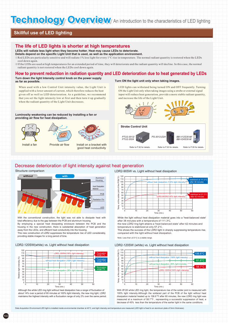
103
With the conventional construction, the light was not able to dissipate heat with
total effeciency due to the gap between the PCB and aluminum housing.
By employing a special heat dissipating enclosure between the PCB and the
housing in the new construction, there is substantial absorption of heat generation
away from the LEDs, and efficient heat conductivity into the housing.
This new construction of LDR2 suppresses the temperature rise of LED considerably,
providing stable images for a long period of time.
Although the white LED ring light without heat dissipation has a range of fluctuation of
about 14% over a period of 60 minutes at 100% light intensity, the new ring light, LDR2
maintains the highest intensity with a fluctuation range of only 2% over the same period.
Technology OverviewTechnology Overview An introduction to the characteristics of LED lighting
Skillful use of LED lighting
The life of LED lights is shorter at high temperaturesLEDs will radiate less light when they become hotter. Heat may cause LEDs to deteriorate.Details depend on the specific Light Unit that is used, as well as the application environment.
How to prevent reduction in radiation quantity and LED deterioration due to heat generated by LEDsTurn down the light Intensity control knob on the power supply as far as possible.
Luminosity weakening can be reduced by installing a fan or providing air flow for heat dissipation.
Install a fan Provide air flow Install on a bracket withgood heat conductivity Refer to P.93 for details.Refer to P.92 for details. Refer to P.95 for details.
PTU2-3012/
PTU2-3024
PS-3012-D24 BB-V12S30-M/
BB-V24S30-M
Turn ON the light unit only when taking images.
Strobe Control Unit
Red LEDs are particularly sensitive and will radiate 1% less light for every 1°C rise in temperature. The normal radiant quantity is restored when the LEDs
cool down again.
If the LEDs are used at high temperatures for an extended period of time, they will deteriorate and the radiant quantity will decline. In this case, the normal
radiant quantity is not restored when the LEDs cool down again.
When used with a low Control Unit intensity value, the Light Unit is
supplied with a lower amount of current, which therefore reduces the heat
given off as well as LED deterioration. As a guideline, we recommend
that you set the light intensity low at first and then turn it up gradually
when the radiant quantity of the Light Unit decreases.
LED lights can withstand being turned ON and OFF frequently. Turning
ON the Light Unit only when taking images using a strobe or external signal
input will reduce heat generation, provide a more stable radiant quantity,
and increase the life of the Light Unit.
Data Acquisition Environment:LED light is installed inside environmental chamber at 40°C, and light intensity and temperature are measured (LED light is fixed to an aluminum plate of 5mm thickness).
Note: Less than 0.5 is a stable range.
Decrease deterioration of light intensity against heat generationStructure comparison LDR2-90SW vs. Light without heat dissipation
without withAluminum
Housing
PCB
LED
Radiation Fin
Heat Dissipation
Material
While the light without heat dissipation material goes into a 'heat-balanced state'
after 38 minutes with a temperature of 111.3 ,
the new LDR2 ring light attains a 'heat-balanced state' after 42 minutes and
temperature is stabilized at only 57.2 .
This shows the success of the LDR2 light in sharply suppressing temperature rise,
compared with the light without heat dissipation.
With 120 white LED ring light, the temperature rise of the solder joint is measured with
100% light intensity.Although the soldered part of the PCB of the light without heat
dissipation material heated up to 106.6 after 60 minutes, the new LDR2 ring light was
measured at a maximum of 58.7 , representing a successful suppression of heat, a
decrease of 45% less than the temperature of the earlier light in the same conditions.
LDR2-120SW (white) vs. Light without heat dissipationLDR2-120SW(white) vs. Light without heat dissipation

104
Light Spectrum
The following figures show the spectral distribution and peak emission wavelength (typ) for different colors of LEDs. Each LED has a unique distribution, which affects the camera when photographing. A good image cannot be obtained if the light spectral distribution and camera sensor’s spectral sensitivity are mismatched.
550 600 650 700 750 800 850 900 950 1000 1050500450
Wavelength (nm)
4003503000
20
100
80
60
40
Rela
tive lum
inous inte
nsity (
%)
UV light:365 nm
Green light:525 nm
Infrared light: 850 nm
Red light: 660 nm(RD)
White light
Infrared light:940 nm
Blue light:470 nm
LED Radiation Pattern
The following figures show the directional dependence of an LED’s relative radiation intensity. The radiation intensity generally shows a maximum along the optical axis and reduces as the angle away from the optical axis increases. Different LED characteristics are used for the CCS narrow type (N) and wide type (W or WD) LEDs.
Directional pattern of White LED Directional pattern of Blue LED
20
40
60
80
+80°
+60°
+40°
-20° -10°-30° +20°+10° +30°0°
-80°
-60°
-40°
+90°-90°
+70°-70°
+50°-50°
0
20
40
60
80
20
40
60
80
+80°
+60°
+40°
-20°-10°-30° +20°+10° +30°0°
-80°
-60°
-40°
+90°-90°
+70°-70°
+50°-50°
0
20
40
60
80
Rela
tive lu
min
ous in
tensity
(%)
Rela
tive lu
min
ous in
tensity
(%)
Directional pattern of Green LED
20
40
60
80
+80°
+60°
+40°
-20° -10°-30° +20°+10° +30°0°
-80°
-60°
-40°
+90°-90°
+70°-70°
+50°-50°
0
20
40
60
80
Rela
tive lu
min
ous in
tensity
(%)
Directional Pattern of Ultraviolet LED
20
40
60
80
0
20
40
60
80
+80°
+60°
+40°
-20°-10°-30° +20°+10° +30°0°
-80°
-60°
-40°
+90°-90°
+70°-70°
+50°-50°
Rela
tive lu
min
ous in
tensity
(%)
Directional Pattern of Red LED N-type for LDL2 Series
Directional Pattern of Red LED W-type for LDL2 Series
20
40
60
80
20
40
60
80
+80°
+60°
+40°
-20°-10°-30° +20°+10° +30°0°
-80°
-60°
-40°
+90°-90°
+70°-70°
+50°-50°
0
Rela
tive lu
min
ous in
tensity
(%)
20
40
60
80
20
40
60
80
+80°
+60°
+40°
-20°-10°-30° +20°+10° +30°0°
-80°
-60°
-40°
+90°-90°
+70°-70°
+50°-50°
Rela
tive lu
min
ous in
tensity
(%)
0
Directional pattern of Red LED N-type(Model:RD)
20
40
60
80
0
20
40
60
80
+80°
+60°
+40°
-20°-10°-30° +20°+10° +30°0°
-80°
-60°
-40°
+90°-90°
+70°-70°
+50°-50°
Rela
tive lu
min
ous in
tensity
(%)
Directional pattern of Red LED W-type(Model:RD)
20
40
60
80
+80°
+60°
+40°
-20°-10°-30° +20°+10° +30°0°
-80°
-60°
-40°
+90°-90°
+70°-70°
+50°-50°
0
20
40
60
80
Rela
tive lu
min
ous in
tensity
(%)
Directional pattern of Red LED N-type(Model:RD2)
20
40
60
80
0
20
40
60
80
+80°
+60°
+40°
-20°-10°-30° +20°+10° +30°0°
-80°
-60°
-40°
+90°-90°
+70°-70°
+50°-50°
Rela
tive lu
min
ous in
tensity
(%)
Directional pattern of Red LED WD-type(Model:RD2)
20
40
60
80
+80°
+60°
+40°
-20°-10°-30° +20°+10° +30°0°
-80°
-60°
-40°
+90°-90°
+70°-70°
+50°-50°
0
20
40
60
80
Rela
tive lu
min
ous in
tensity
(%)
Red light: 630 nm(RD2)
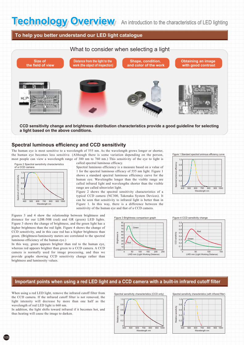
105
To help you better understand our LED light catalogue
Technology OverviewTechnology Overview An introduction to the characteristics of LED lighting
Distance from the light to the work (the object of inspection)
Shape, condition, and color of the work
Size of the field of view
Obtaining an image with good contrast
Spectral luminous efficiency and CCD sensitivity
CCD sensitivity change and brightness distribution characteristics provide a good guideline for selecting a light based on the above conditions.
The human eye is most sensitive to a wavelength of 555 nm. As the wavelength grows longer or shorter,
the human eye becomes less sensitive. (Although there is some variation depending on the person,
most people can view a wavelength range of 380 nm to 760 nm.) This sensitivity of the eye to light is
called spectral luminous efficacy.
Spectral luminous efficiency is a measure based on a value of
1 for the spectral luminous efficacy of 555 nm light. Figure 1
shows a standard spectral luminous efficiency curve for the
human eye. Wavelengths longer than the visible range are
called infrared light and wavelengths shorter than the visible
range are called ultraviolet light.
Figure 2 shows the spectral sensitivity characteristics of a
typical CCD camera (NC300, Takenaka System Devices). It
can be seen that sensitivity to infrared light is better than in
Figure 1. In this way, there is a difference between the
sensitivity of the human eye and that of a CCD camera.
Figures 3 and 4 show the relationship between brightness and
distance for our LDR-50B (red) and GR (green) LED lights.
Figure 3 shows the change of brightness, and the green light has a
higher brightness than the red light. Figure 4 shows the change of
CCD sensitivity, and in this case red has a higher brightness than
green. (Brightness/luminosity meters are correlated to the spectral
luminous efficiency of the human eye.)
In this way, green appears brighter than red to the human eye,
whereas red appears brighter than green to a CCD camera. A CCD
camera is normally used for image processing, and thus we
provide graphs showing CCD sensitivity change rather than
brightness and luminosity values.
Important points when using a red LED light and a CCD camera with a built-in infrared cutoff filter
When using a red LED light, remove the infrared cutoff filter from
the CCD camera. If the infrared cutoff filter is not removed, the
light intensity will decrease by more than one half as the
wavelength of red LED light is 660 nm.
In addition, the light shifts toward infrared if it becomes hot, and
thus heating will cause the image to darken.
What to consider when selecting a lightWhat to consider when selecting a light
1.0
0.8
0.6
0.4
0.2
0400 500 600 700
Wavelength nm
800 900 1000
Spectr
um
of
CC
D s
ensitiv
ity
Figure 2 Spectral sensitivity characteristics of a CCD camera
1.0
0.8
0.6
0.4
0.2
0400 500 600 700
Wavelength nm
800 900 1000
Spectr
al lu
min
ous e
ffic
iency
Figure 1 Standard spectral luminous efficiency curve
Figure 4 CCD sensitivity changeFigure 3 Brightness comparison graph
90
80
70
60
50
40
30
20
10
00 50 100 150 200 250
LWD mm (Light Working Distance)
Brig
htn
ess lx
(1000)
Green
Red
0.8
0.7
0.6
0.5
0.4
0.3
0.2
0.1
00 50 100 150
LWD mm (Light Working Distance)
CC
D s
en
sitiv
ity
Red
Green
1.0
0.8
0.6
0.4
0.2
0400 500 600 700
Wavelength nm
800 900 1000
Rela
tive s
ensitiv
ity
Spectral sensitivity characteristics (CCD only) Spectral sensitivity characteristics (with infrared filter)
1.0
0.8
0.6
0.4
0.2
0400 500 600 700
Wavelength nm
800 900 1000
Rela
tive s
ensitiv
ity
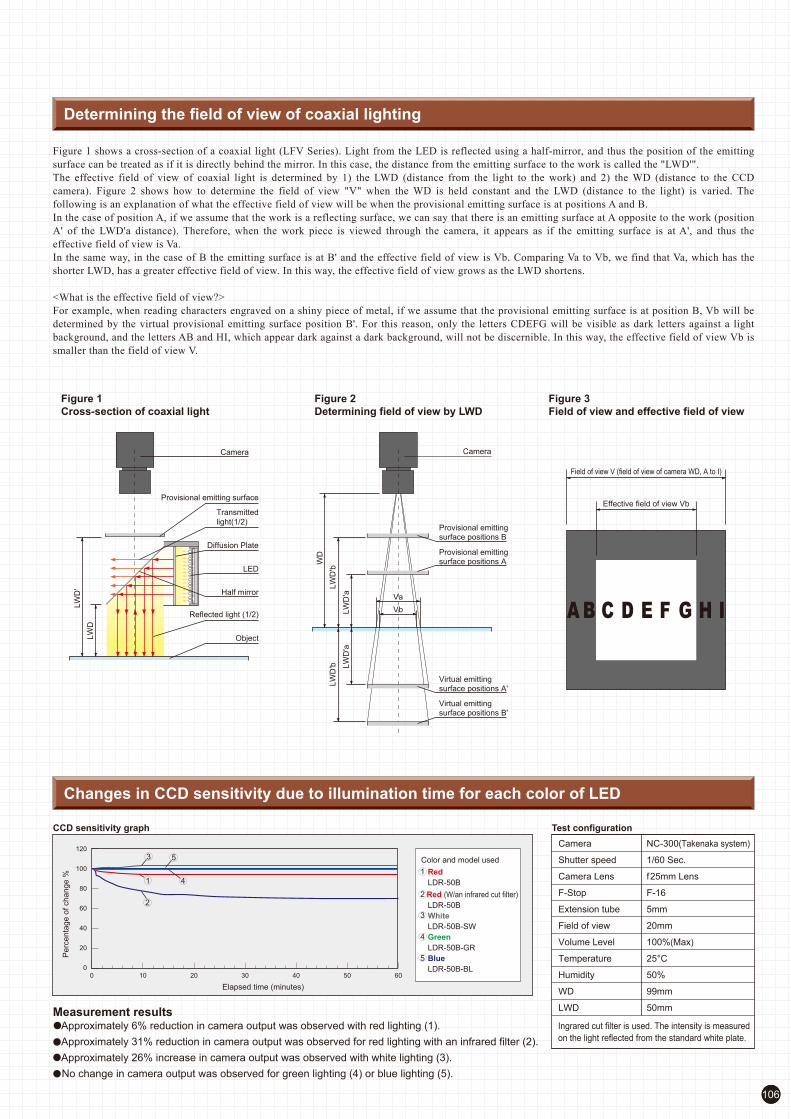
106
Ingrared cut filter is used. The intensity is measured
on the light reflected from the standard white plate.
Figure 1 shows a cross-section of a coaxial light (LFV Series). Light from the LED is reflected using a half-mirror, and thus the position of the emitting
surface can be treated as if it is directly behind the mirror. In this case, the distance from the emitting surface to the work is called the "LWD'".
The effective field of view of coaxial light is determined by 1) the LWD (distance from the light to the work) and 2) the WD (distance to the CCD
camera). Figure 2 shows how to determine the field of view "V" when the WD is held constant and the LWD (distance to the light) is varied. The
following is an explanation of what the effective field of view will be when the provisional emitting surface is at positions A and B.
In the case of position A, if we assume that the work is a reflecting surface, we can say that there is an emitting surface at A opposite to the work (position
A' of the LWD'a distance). Therefore, when the work piece is viewed through the camera, it appears as if the emitting surface is at A', and thus the
effective field of view is Va.
In the same way, in the case of B the emitting surface is at B' and the effective field of view is Vb. Comparing Va to Vb, we find that Va, which has the
shorter LWD, has a greater effective field of view. In this way, the effective field of view grows as the LWD shortens.
<What is the effective field of view?>
For example, when reading characters engraved on a shiny piece of metal, if we assume that the provisional emitting surface is at position B, Vb will be
determined by the virtual provisional emitting surface position B'. For this reason, only the letters CDEFG will be visible as dark letters against a light
background, and the letters AB and HI, which appear dark against a dark background, will not be discernible. In this way, the effective field of view Vb is
smaller than the field of view V.
Determining the field of view of coaxial lighting
Figure 2
Determining field of view by LWD
Figure 1
Cross-section of coaxial light
Figure 3
Field of view and effective field of view
Object
Reflected light (1/2)
Diffusion Plate
LW
D'
LW
D
Transmitted
light(1/2)
LED
Field of view V (field of view of camera WD, A to I)
Effective field of view Vb
Half mirror
Camera
Va
Vb
WD
LW
D'b
LW
D'b
LW
D'a
LW
D'a
Camera
Provisional emittingsurface positions A
Provisional emittingsurface positions B
Virtual emittingsurface positions B'
Virtual emittingsurface positions A'
Provisional emitting surface
Test configuration
Changes in CCD sensitivity due to illumination time for each color of LED
Measurement results Approximately 6% reduction in camera output was observed with red lighting (1).
Approximately 31% reduction in camera output was observed for red lighting with an infrared filter (2).
Approximately 26% increase in camera output was observed with white lighting (3).
No change in camera output was observed for green lighting (4) or blue lighting (5).
Color and model used
Red
LDR-50B
Red (W/an infrared cut filter)
LDR-50B
White
LDR-50B-SW
Green
LDR-50B-GR
Blue
LDR-50B-BL
Camera
Shutter speed
Camera Lens
F-Stop
Extension tube
Field of view
Volume Level
Temperature
Humidity
WD
LWD
NC-300(Takenaka system)
1/60 Sec.
f25mm Lens
F-16
5mm
20mm
100%(Max)
25°C
50%
99mm
50mm
CCD sensitivity graph
Pe
rcenta
ge o
f change %
Elapsed time (minutes)
120
100
80
60
40
20
00 10 20 30 40 50 60
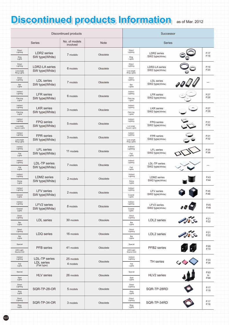
No. of modelsinvolved
NoteSeries
Discontinued products
Series
Successor
LDR2 series
SW type(White)RingLights
DirectLighting
LDR2 seriesSW2 type(White)Ring
Lights
DirectLighting
7 models Obsolete
LDR2-LA series
SW type(White)Low-angleRing Lights
DirectLighting
LDR2-LA seriesSW2 type(White)Low-angle
Ring Lights
DirectLighting
6 models Obsolete
LDL series
SW type(White)BarLights
DirectLighting
LDL seriesSW2 type(White)Bar
Lights
DirectLighting
7 models Obsolete
P.17
P.18
P.19
P.20
-
FPQ series
SW type(White)Low-angleSquare Lights
IndirectLighting
FPQ seriesSW2 type(White)Low-angle
Square Lights
IndirectLighting
5 models ObsoleteP.31
P.32
LFR series
SW type(White)Flat-ringLights
IndirectLighting
LFR seriesSW2 type(White)Flat-ring
Lights
IndirectLighting
6 models ObsoleteP.27
P.28
LFL series
SW type(White)FlatLights
IndirectLighting
LFL seriesSW2 type(White)Flat
Lights
IndirectLighting
11 models ObsoleteP.35
P.36
LFV series LFV series
SW type(White)CoaxialLights
IndirectLighting
SW2 type(White)CoaxialLights
IndirectLighting
2 models ObsoleteP.45
P.46
LDL-TP series
SW type(White)FlatLights
IndirectLighting
LDL-TP seriesSW2 type(White)Flat
Lights
IndirectLighting
7 models Obsolete -
FPR series
SW type(White)Low-angleRing Lights
IndirectLighting
FPR seriesSW2 type(White)Low-angle
Ring Lights
IndirectLighting
3 models ObsoleteP.31
P.32
LKR series
SW type(White)Flat-ringLights
IndirectLighting
LKR seriesSW2 type(White)Flat-ring
Lights
IndirectLighting
3 models ObsoleteP.27
P.28
LDM2 series
SW type(White)DomeLights
IndirectLighting
LDM2 seriesSW2 type(White)Dome
Lights
IndirectLighting
2 models ObsoleteP.43
P.44
LDL series LDL2 seriesBar
Lights
DirectLighting
BarLights
DirectLighting
30 models ObsoleteP.21
P.22
LFV2 series
SW type(White)CoaxialLights
IndirectLighting
LFV2 seriesSW2 type(White)Coaxial
Lights
IndirectLighting
8 models ObsoleteP.45
P.46
LDQ series LDL2 seriesBar
Lights
DirectLighting
BarLights
DirectLighting
16 models ObsoleteP.21
P.22
PFB series PFB2 seriesLED Light Source Unit
Special
LED Light Source Unit
Special
41 models ObsoleteP.69
P.70
LDL-TP seriesLDL series
(Flat type)
TH seriesFlat
Lights
IndirectLighting
FlatLights
IndirectLighting
4 models
25 modelsObsolete
P.33
P.34
HLV series HLV2 seriesSpot
Lights
Special Special
SpotLights
26 models ObsoleteP.63
to
P.68
SQR-TP-28-OR SQR-TP-28RDRing
Lights
DirectLighting
RingLights
DirectLighting
5 models ObsoleteP.17
P.18
SQR-TP-34-OR SQR-TP-34RDRing
Lights
DirectLighting
RingLights
DirectLighting
3 models ObsoleteP.17
P.18
107
Discontinued products InformationDiscontinued products Information as of Mar. 2012

HSL series
PSB2 series
High Intensity Spot Lights
Special
1 models Obsolete
Obsolete
PHL-0508-CD24 1 models Obsolete
RingLights
DirectLighting
RingLights
DirectLighting
DirectLighting
DirectLighting
7 models
Supply until
April 15, 2013
Supply until
April 15, 2013
Supply until
April 15, 2013P.17
P.18
Low-angle Ring Lights
DirectLighting
Low-angle Ring Lights
6 modelsP.19
P.20
RingLights
DirectLighting
SpotLights
1 modelsP.17
P.18
Low-angle Ring Lights
DirectLighting
Low-angle Ring Lights
DirectLighting
5 modelsSupply until
April 15, 2013
P.19
P.20
Flat-ringLights
IndirectLighting
Flat-ringLights
IndirectLighting
7 modelsSupply until
April 15, 2013
Supply until
April 15, 2013
Supply until
April 15, 2013
Supply until
April 15, 2013
Supply until
April 15, 2013
Supply until
April 15, 2013
Supply until
April 15, 2013
Supply until
April 15, 2013
Supply until
April 15, 2013
P.27
P.28
PSB3-30024ControlUnits
ControlUnits
ControlUnits2 models
P.89
P.90
Flat-ringLights
IndirectLighting
Flat-ringLights
IndirectLighting
3 modelsP.27
P.28
Low-angleRing Lights
IndirectLighting
Low-angleRing Lights
IndirectLighting
3 modelsP.31
P.32
FlatLights
IndirectLighting
FlatLights
IndirectLighting
11 modelsP.35
P.36
DomeLights
IndirectLighting
DomeLights
IndirectLighting
2 modelsP.43
P.44
CoaxialLights
CollimatedLighting
CoaxialLights
CollimatedLighting
3 modelsP.57
P.58
SpotLights
Special Special
SpotLights
1 models P.74
Low-angle Square Lighting
IndirectLighting
Low-angle Square Lighting
IndirectLighting
5 modelsP.29
P.30
Flat-DomeLights
IndirectLighting
Flat-DomeLights
IndirectLighting
3 modelsP.37
P.38
LDR2 series
RD type(Red)
SQR series
RD type(Red)
SQR series
RD2 type(Red)
LDR2-LA series
RD type(Red)
LDR-LA-1 series
RD type(Red)
LFR series
RD type(Red)
LKR series
RD type(Red)
FPR series
RD type(Red)
LFL series
RD type(Red)
LDM2 series
RD type(Red)
MSU series
RD type(Red)
MSU series
RD2 type(Red)
LDM2 series
RD2 type(Red)
LFL series
RD2 type(Red)
FPR series
RD2 type(Red)
LKR series
RD2 type(Red)
LFR series
RD2 type(Red)
LDR-LA1 series
RD2 type(Red)
LDR2-LA series
RD2 type(Red)
LDR2 series
RD2 type(Red)
LV series
RD type(Red)
LV series
RD2 type(Red)
FPQ series
LFX series LFX2 series
FPQ2 series
No. of modelsinvolved
NoteSeries
Discontinued products
Series
Successor
108
Note: Please refer to CCS Web site for more details. http://www.ccs-grp.com/s2_ps/s1/s_05/product-2011.html

109
CCS Worldwide SupportWe will satisty your needs with variousproducts.
CCS Worldwide SupportWe will satisty your needs with variousproducts.
CCS provides lighting solutions and technical consultation on locations worldwide so that you can choose the best illumination.Please feel free to contact us. All locations have testing rooms where you can do experiments of your workpieces with our lightings.(Please make an appointment in advance.)
Testing RoomProducts Display Shelf
Testing RoomCCS's strong product lineup meets your diverse lighting needs.
CCS World Wide NetworkFor your nearest sales representative, please visit our website.
CCS World Wide Network
Dedicated staff provide consultations for the selection of lighting and technical inquiries.
For your nearest sales representative, please visit our website.
Customer service support locations all over the worldProvides lighting solutions and technical support.
CCS Inc. (Headquarters)
Tokyo Sales Office/ Testing Room
Shimodachiuri-agaru, karasuma-dori, kamigyo-ku, Kyoto 602-8011 JAPAN International Sales Department
TEL : +81-75-415-8284FAX : +81-75-415-8278
Kyoto subway karasuma line Marutamachi station Exit2 (5 min,to North on foot)
11F Asahi Mutual Life Insurance Co. Ebisu Building 1-3-1, Ebisu, Shibuya-ku, Tokyo 150-0013, Japan
TEL : +81-3-5791-3701FAX : +81-3-5791-3704
3 minutes walk from Ebisu Station, of both JR Yamanote Line and Hibiya Subway Line
PalacesideHotel
Goou shrine
Police
office
McDonald's
Ka
rasu
ma
-do
ri
Kyoto
gyoen
Kyoto
Prefectual
office
N
JR line Kyoto station
Kyoto subway karasuma line Marutamachi station Exit2
Shimochoja machi-dori
Shimodachiuri-dori
Subway Hibiya Line
Ebisu Sta.
Komazawa-D
ori
EBIS Q PLAZA
JR E
bisu
Sta
tion
Yam
anote
Lin
e
Meiji-Dori
Asahi Mutual Life
Insurance Co.
Ebisu Building

110
CCS Europe NV/SA
Bergensesteenweg 423, Bus 13 1600 Sint-Pieters-Leeuw, Belgium
TEL : +32-(0)2-333-0080FAX : +32-(0)2-333-0081Email : [email protected]
CCS Inc. Shanghai Office
Room 308B-309, CIMIC Tower No.1090 Century Avenue, Pu Dong New Area, Shanghai 200120, P.R. China
TEL : +86-21-5835-8728FAX : +86-21-5835-8928Email : [email protected]
CCS America Inc.
5 Burlington Woods Suite 204Burlington, MA 01803 USA
TEL : +1-781-272-6900FAX : +1-781-272-6902Email : [email protected]
CCS Inc. Shenzhen office
17B,China Economic Trade Building,
7Rd Zizhu,Zhuzilin,Futian District,
Shenzhen 518040 P.R.China
TEL : +86-755-8279-0477
FAX : +86-755-8279-0478 Email : [email protected]
CCS Asia PTE LTD.
63 Hillview Avenue #07-10, Lam Soon Industrial Building, Singapore 669569
TEL : +65-6769-1669FAX : +65-6769-3422Email : [email protected]
Kunball Ave
128
3A
95
95
Lahey Clinic
Medical Center
Mild
red
Rd
Barb
ara C
ir
Mic
hele
Dr
Ways
ide R
d
Cam
brid
ge S
t
Burlington M
a ll RdS B
edford St
United
Cart Park
Burlin
gton
WSD
E19/A7
Ruisbroeksesteenweg
ZUUN
Berg
ense
steenw
eg
Mee
rweg
RUISBROEKRUISBROEK
Fabrie
kstra
at
HUME
HILLVIEW
GREEN
CHANTILLY
RISE
HILLBROOKS
INTAN
BATU
CENTURY
MANSIONS
HILLVIEW
HOUSE
GUMILANG
JLN
REMAJA
KEWALRAM
HILLVIEW
AVE
GLENSPRINGS
HILLVIEW
APARTMENTSHILLVIEW CARS
PLAYGROUND
LAM SOON
IND BLDG
Pu
Don
g S.R
d.
Don
g Fon
g R
d.
Pu Dong Rj.
Zhang Yang Rd.
Huang Pu Jiang
Lao S
han E
.Rd.
Lao S
han E
.Rd.
Dong Chang Lu(Subwey)Dong Chang Lu(Subwey)
CIMIC TowerCIMIC Tower

Notes:
Examples of workpiece imaging in this catalog are a guide that may be informative for choosing illuminators. Please check the functions of the equipment and
requirements when choosing.In addition, the sample workpieces that are used are processed by us and do not represent the original quality and performance.
Carefully read the product's instruction manual before use to ensure correct operation. Product specifications and design are subject to change without notice.
Many of our products are protected by intellectual property rights (patents, industrial designs, and trademarks).
Be warned against imitations of the CCS brand.*
HeadquartersShimodachiuri-agaru, Karasuma-dori, Kamigyo-ku, Kyoto 602-8011 Japan
Phone: +81-75-415-8284 / Fax: +81-75-415-8278
URL: http://www.ccs-grp.com
E-mail: [email protected]
Copyright(c) 2012 CCS Inc. All Rights Reserved.
Descriptions in this catalog are based on information available as of March 2012. 02001-14-0409
CCS website
http://www.ccs-grp.com
All products listed in this catalog comply with the RoHS Directive.
CCS Corporate Profile Machine Vision Applications Machine Vision Applications Topics
Product InformationProduct information, such as specifications
and accessories, is provided. Downloadable
information is also provided.
New RegistrationIf you register as a CCS member, you can download
all materials (such as PDF or DXF drawings and
operation manuals) from our website. You can also
send in applications for selecting the appropriate
Light Unit or borrowing Demonstration Units, and
post requests for estimates or for catalogs. Go ahead
and register as a member.
Direct Number A direct number is a 7-digit number assigned to a CCS
product. You can easily access the web page providing
information on any desired product by simply
entering the direct number in the field provided.
The direct number assigned to each product is listed in
the Direct Number Table or on the product web page.
Download the Direct Number Table to find direct
numbers that are not listed in this catalog. Refer to
Direct Numbers under the Services and Support page
for details.
http://www.ccs-grp.com/s6_common/direct.html
DownloadsThis page is for downloading 3D-CAD
drawings, PDF drawings, DXF drawings,
operation manuals, PDF catalogs, and PDF
brochures.
Services and SupportItems such as Warranty Information,
Repairs, FAQs, Domestic and Overseas
Branches, Testing Rooms, are listed.
Contacting CCSInquiries on LED Lighting, Borrowing
Products, Estimates, Requests for Catalogs,
Product-related Questions, and Other
Questions are handled from this web page.
New ProductsInformation on new and popular products is
provided.
Registration for New CCS Members
Direct Number Input Fields


![NTCIR-10 Crosslink Taskresearch.nii.ac.jp/ntcir/IPSJ_IFAT_DD_Crosslink.pdf(2010),[178] Australia is the world's thirteenth largest economy and has the ninth highest per capita GDP;](https://static.documents.pub/doc/80x56/606f247cb173b71f0e68d4cf/ntcir-10-crosslink-2010178-australia-is-the-worlds-thirteenth-largest-economy.jpg)


![DD TThhrreeee GGoorrggee ZZhhaannggJJiiaaJJiiee...~Gemstone Shop~10 Miles GalleryIncl.02ways Sightseeing Train~Tea Shop [Glass Bridge @ Grand Canyon] The world's longest and highest](https://static.documents.pub/doc/80x56/5e8b60cc8a6dd601150522b2/dd-tthhrreeee-ggoorrggee-zzhhaannggjjiiaajjiiee-gemstone-shop10-miles-galleryincl02ways.jpg)


