Informal document No. 15 (46th GRPE, 19-23 May 2003, agenda item 3.) Note by the secretariat : As part of the secretariat's efforts to reduce expenditure, this voluminous informal document No. 15 will not be distributed during the 46th GRPE session. Delegates are kindly requested to bring their copies of this document to the meeting. Worldwide Harmonised Motorcycle Emissions Certification Procedure [DRAFT GLOBAL TECHNICAL REGULATION (GTR)] UN/ECE-WP 29 - GRPE WMTC Working Group Whilst this document is presented in the format of a draft GTR as defined by WP.29 / 883, the WMTC FEG / WMTC informal group / GRPE recognise that the issue of GTR’s and specific performance requirements / limit values is still being considered. Accordingly WMTC FEG / WMTC informal group / GRPE will finalise the document once WP.29 / AC.3 has reached a decision. Indications for missing parts or parts that need to be modified are written in blue starting with “xxxxx”. Draft Version 10.05.2003
Note by the secretariat: As part of the secretariat's efforts to reduce expenditure, this voluminous informal document No. 15 will not be distributed during the 46th GRPE session. Delegates are kindly requested to bring their copies of this document to the meeting.
Whilst this document is presented in the format of a draft GTR as defined by WP.29 / 883, the WMTC FEG / WMTC informal group / GRPE recognise that the issue of GTR’s and specific performance requirements / limit values is still being considered. Accordingly WMTC FEG / WMTC informal group / GRPE will finalise the document once WP.29 / AC.3 has reached a decision.
Indications for missing parts or parts that need to be modified are written in blue starting with “xxxxx”.
Draft Version 10.05.2003
EUNITED NATIONS
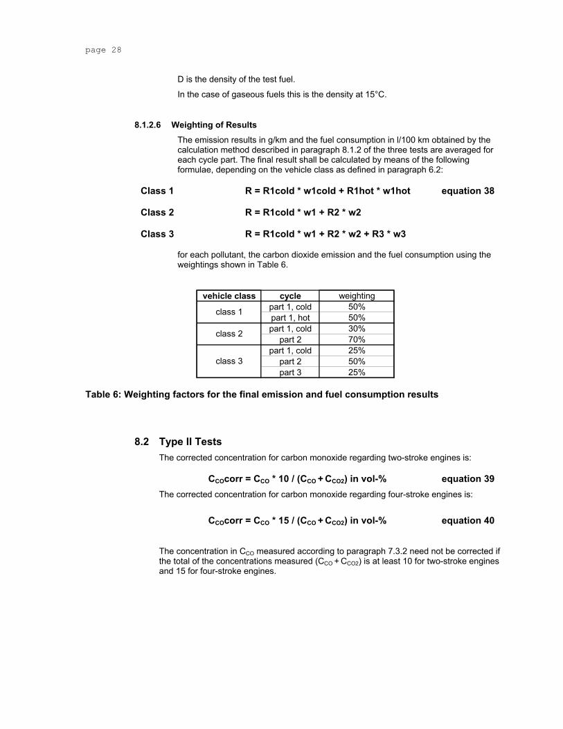
Distr.
Economic and Social GENERAL
Council TRANS/WP.29/xxx
Draft Version 07.05.2003
ENGLISH
Original: ENGLISH
ECONOMIC COMMISSION FOR EUROPE
INLAND TRANSPORT COMMITTEE
World Forum for Harmonisation of Vehicle Regulations (WP.29)
[DRAFT GLOBAL TECHNICAL REGULATION (GTR)]
UNIFORM PROVISIONS CONCERNING THE MEASUREMENT PROCEDURE FOR MOTORCYCLES
EQUIPPED WITH A POSITIVE -IGNITION ENGINE WITH REGARD TO THE EMISSION
OF GASEOUS POLLUTANTS, CO2 EMISSIONS AND FUEL CONSUMPTION BY THE ENGINE
__________
Content Page
A. Statement of Technical Rationale and Justification....................................................................5 B. Text of Regulation ..........................................................................................................................6 1 Scope and Purpose ........................................................................................................................6 2 Application ......................................................................................................................................6 3 Definitions .......................................................................................................................................6 3.1 Vehicle Type....................................................................................................................................6 3.1.1 Equivalent Inertia............................................................................................................................6 3.1.2 Engine and Vehicle Characteristics..............................................................................................6 3.2 Vehicle Mass ...................................................................................................................................6 3.2.1 Kerb Mass........................................................................................................................................6 3.3 Reference Mass ..............................................................................................................................6 3.4 Engine Crank-case .........................................................................................................................7 3.5 Gaseous Pollutants ........................................................................................................................7 3.6 CO2 Emissions ...............................................................................................................................7 3.7 Fuel Consumption ..........................................................................................................................7 3.8 Maximum Vehicle Speed vmax ........................................................................................................7 3.9 Symbols used .................................................................................................................................7 4 General Requirements .................................................................................................................11 5 [Performance Requirements] ......................................................................................................11 6 Test Conditions.............................................................................................................................11 6.1 Test Vehicle...................................................................................................................................11 6.1.1 General ..........................................................................................................................................11 6.1.2 Run-in ............................................................................................................................................11 6.1.3 Adjustments..................................................................................................................................11 6.1.4 Test Mass and Load Distribution ................................................................................................11 6.1.5 Tyres ..............................................................................................................................................11 6.2 [Vehicle Classification..................................................................................................................11 6.2.1 Class 1 ...........................................................................................................................................11 6.2.2 Class 2 ...........................................................................................................................................12 6.2.3 Class 3 ...........................................................................................................................................12 6.3 Specification of Reference Fuel ..................................................................................................12 6.3.1 TECHNICAL DATA OF THE REFERENCE FUEL TO BE USED FOR TESTING VEHICLES
EQUIPPED WITH POSITIVE-IGNITION ENGINES.......................................................................12 6.3.2 TECHNICAL DATA OF THE REFERENCE FUEL TO BE USED FOR TESTING VEHICLES
EQUIPPED WITH A DIESEL ENGINE ..........................................................................................15 6.3.3 Specification of Gaseous Reference Fuel ....................................................................................2 6.4 Type I Tests .....................................................................................................................................4 6.4.1 Rider.................................................................................................................................................4 6.4.2 Test Bench Specifications and Settings ......................................................................................4 6.4.3 Exhaust Gas Measurement System..............................................................................................5 6.4.4 Driving Schedules ..........................................................................................................................6 6.4.5 Gearshift Prescriptions..................................................................................................................7 6.4.6 Dynamometer Settings...................................................................................................................9 6.4.7 Measurement Accuracies ............................................................................................................14 6.5 Type II Tests ..................................................................................................................................14 6.5.1 Application ....................................................................................................................................14 6.5.2 Test Fuel. .......................................................................................................................................14 6.5.3 Measured Gaseous Pollutant. .....................................................................................................14 6.5.4 Engine Test Speeds......................................................................................................................14 6.5.5 Gear Lever Position......................................................................................................................15 7 Test Procedures............................................................................................................................15 7.1 Description of Tests. ....................................................................................................................15 7.1.1 Type-I Test (verifying the average emission of gaseous pollutants, CO2 emissions and
fuel consumption in a characteristic driving cycle). .................................................................15 7.1.2 Type-II Test (test of carbon monoxide at idling speed) and emissions data required for
7.2 Type I Tests ...................................................................................................................................15 7.2.1 Overview........................................................................................................................................15 7.2.2 Dynamometer Settings and Verification.....................................................................................16 7.2.3 Calibration of Analysers ..............................................................................................................19 7.2.4 Vehicle Preconditioning...............................................................................................................19 7.2.5 Emissions Tests ...........................................................................................................................20 7.2.6 Drive Instructions .........................................................................................................................21 7.2.7 Dynamometer Test Runs .............................................................................................................21 7.2.8 Records required..........................................................................................................................22 7.3 Type II Tests ..................................................................................................................................23 7.3.1 Conditions of Measurement ........................................................................................................23 7.3.2 Sampling of Exhaust Gases ........................................................................................................23 8 Analysis of Results.......................................................................................................................23 8.1 Type I Tests ...................................................................................................................................23 8.1.1 Speed Tolerances.........................................................................................................................23 8.1.2 Exhaust Emission and Fuel Consumption Analysis .................................................................24 8.2 Type II Tests ..................................................................................................................................28 9 Annexes.........................................................................................................................................29 9.1 ESSENTIAL CHARACTERISTICS OF THE ENGINE, the reduction systems AND
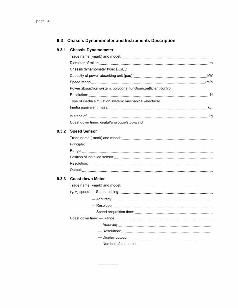
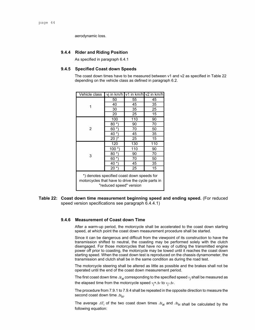
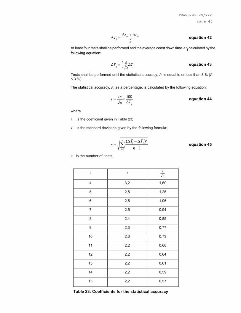
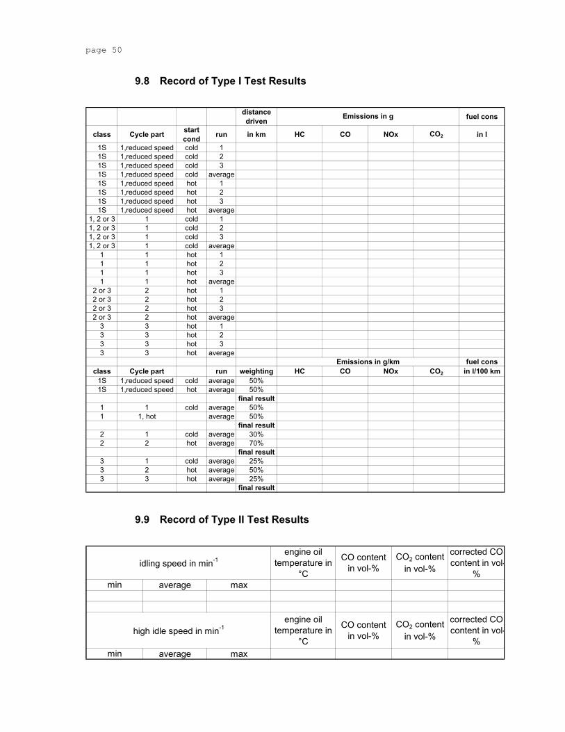
INFORMATION CONCERNING THE CONDUCT OF TESTS.......................................................29 9.2 Driving Cycles for Type I Tests ...................................................................................................34 9.3 Chassis Dynamometer and Instruments Description ...............................................................42 9.3.1 Chassis Dynamometer .................................................................................................................42 9.3.2 Speed Sensor................................................................................................................................42 9.3.3 Coast down Meter.........................................................................................................................42 9.4 Road Tests for the Determination of Test Bench Settings.......................................................43 9.4.1 Requirements for the Rider .........................................................................................................43 9.4.2 Requirement for the Road and Ambient Conditions.................................................................43 9.4.3 Condition of the Vehicle...............................................................................................................43 9.4.4 Rider and Riding Position............................................................................................................44 9.4.5 Specified Coast down Speeds ....................................................................................................44 9.4.6 Measurement of Coast down Time .............................................................................................44 9.4.7 Data Processing............................................................................................................................46 9.5 Form for the Record of Coast down Time..................................................................................47 9.6 Record of chassis dynamometer setting (by coast down method) .........................................48 9.7 Record of chassis dynamometer setting (by table method) ....................................................49 9.8 Record of Type I Test Results .....................................................................................................50 9.9 Record of Type II Test Results ....................................................................................................50 9.10 Gear Use Calculation Routine .....................................................................................................51
A. Statement of Technical Rationale and Justification 1. Technical and Economic Feasibility
The objective is to establish a harmonised Global Technical Regulation (GTR) on the certification procedure for motorcycle exhaust-emissions. The basis will be the harmonised test procedure, developed by the WMTC informal group of GRPE (see draft technical report, informal document no. 9 to 45th GRPE).
Regulations governing the exhaust-emissions from all road vehicles have been in existence for many years but the methods of measurement vary significantly. To be able to correctly determine a vehicle’s impact on the environment in terms of exhaust emissions and its fuel consumption, the test procedure and consequently the GTR needs to adequately represent real-world vehicle operation.
The proposed regulation is based on new research into the world-wide pattern of real motorcycle use. From this data a representative test cycle in three parts has been created, covering different road types. Based on real life data a gearshift procedure was developed. The general laboratory conditions for the emission test have been brought up to date by an expert committee in ISO and now reflect the latest technologies.
This basic test procedure reflects world wide on-road motorcycle operation as closely as possible and enables a realistic assessment of existing and future motorcycle exhaust-emissions.
The weighting factors for calculating the overall emission results from the several cycle parts were calculated from the widest possible statistical basis worldwide. The classification of vehicles reflects the general categories of use and real world driving behaviour.
The performance levels (emissions and fuel consumption results) to be achieved in the GTR will be discussed on the basis of the most recently agreed legislation in the Contracting Party countries, required by the 1998 Agreement. On the basis of measurement results according to this GTR it will be possible to propose limit values that are compatible to existing limit values in different regions/countries.
The question of harmonised off cycle emissions requirements will be considered and appropriate measures introduced in due course.
2. Anticipated Benefits Increasingly, motorcycles are vehicles, which are prepared for the world market. It is economically inefficient for manufacturers to have to prepare substantially different models in order to meet different emission regulations and methods of measuring CO2 / fuel consumption, which are, in principle, aimed at achieving the same objective. To enable manufacturers to develop new models most effectively it is desirable that a GTR should be developed.
Compared to the measurement methods defined in existing legislation in Contracting Party countries the method defined in this GTR is much more representative of motorcycle in-use driving behaviour with respect to the following parameters:
o Max. cycle speed,
o Vehicle acceleration,
o Gearshift prescriptions,
o Cold start consideration.
As a consequence, it can be expected that the application of this GTR for emissions limitation within the type approval procedure will result in a higher severity and higher correlation with in-use emissions.
3. [Potential cost effectiveness] xxxxx not yet clear whether this is requested or not
B. Text of Regulation
1 Scope and Purpose This regulation provides a world-wide harmonised method for the determination of the levels of gaseous pollutant emissions, the emissions of carbon dioxide and the fuel consumption of two -wheel motor vehicles that are representative for real world vehicle operation. The results can build the basis for the limitation of gaseous pollutants and carbon dioxide and for the fuel consumption indicated by the manufacturer within regional type approval procedures.
2 Application This Regulation applies to the emission of gaseous pollutants, carbon dioxide emissions and fuel consumption of two-wheeled motor cycles having a maximum design speed exceeding 50 km/h or cylinder capacity exceeding 50 cm³.
3 Definitions For the purposes of this Regulation,
3.1 Vehicle Type "Vehicle type" means a category of power-driven vehicles that do not differ in the following essential respects as:
3.1.1 Equivalent Inertia The equivalent inertia determined in relation to the reference weight as prescribed in paragraph 6.4.2 to this Regulation, and
3.1.2 Engine and Vehicle Characteristics The engine and vehicle characteristics as defined in annex 9.1 to this Regulation.
3.2 Vehicle Mass
3.2.1 Kerb Mass The kerb mass of motorcycle shall be as follows:
Motorcycle dry mass to which is added the mass of the following:
- fuel: tank filled at least to 90 % of the capacity specified by the manufacturer;
- oils and coolant: filled as specified by the manufacturer;
- auxiliary equipment usually supplied by the manufacturer in addition to that necessary for normal operation tool-kit, carrier(s), windscreen(s), protective equipment, etc.
3.3 Reference Mass "Reference mass" means the kerb mass of the vehicle increased by a uniform figure of 75 kg.
3.4 Engine Crank-case “Engine crank-case" means the spaces in or external to an engine which are connected to the oil sump by internal or external ducts through which gases and vapours can escape.
3.5 Gaseous Pollutants “Gaseous pollutants” means carbon monoxide, oxides of nitrogen expressed in terms of nitrogen dioxide (NO2) equivalence, and hydrocarbons, assuming a ratio of:
C1H1.85 for petrol
C1H1.86 for diesel
3.6 CO2 Emissions “CO2 emissions” means carbon dioxide.
3.7 Fuel Consumption [“Fuel consumption” means the amount of fuel consumed, calculated by the carbon balance method.]
3.8 Maximum Vehicle Speed vmax [vmax is the maximum speed of the vehicle as declared by the manufacturer, measured in accordance with EU directive 95/1/EC.]
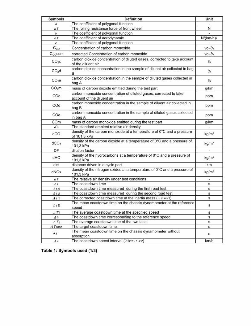
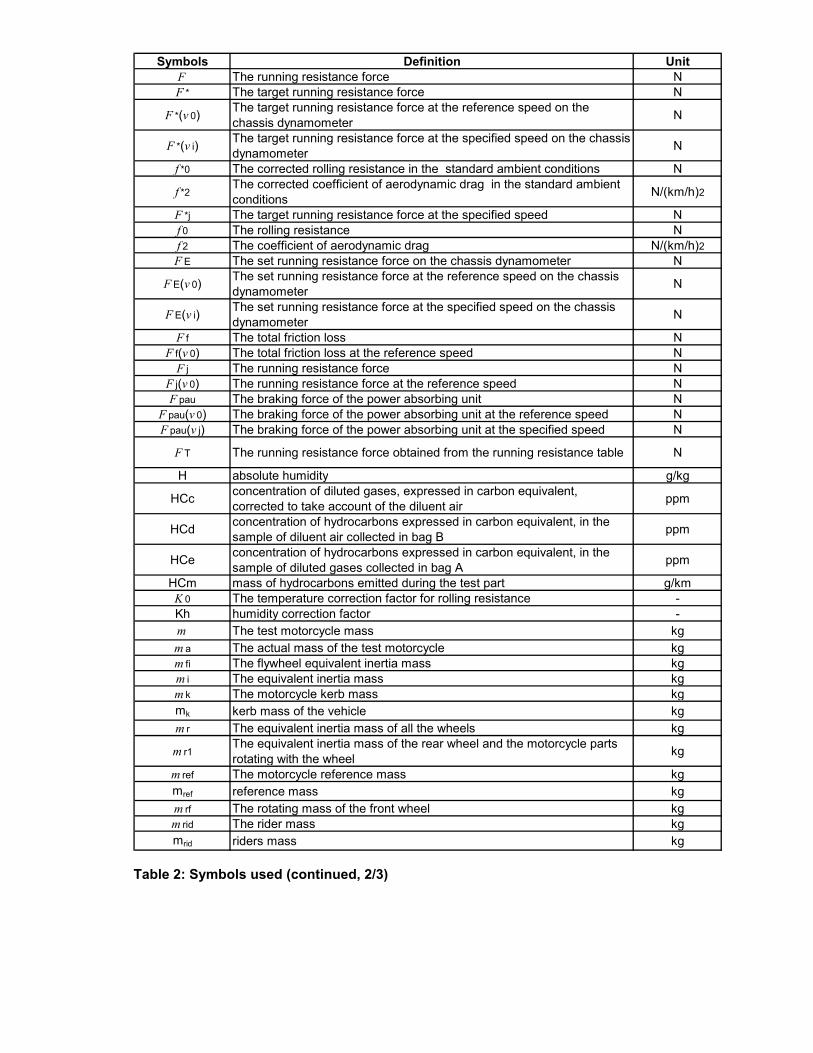
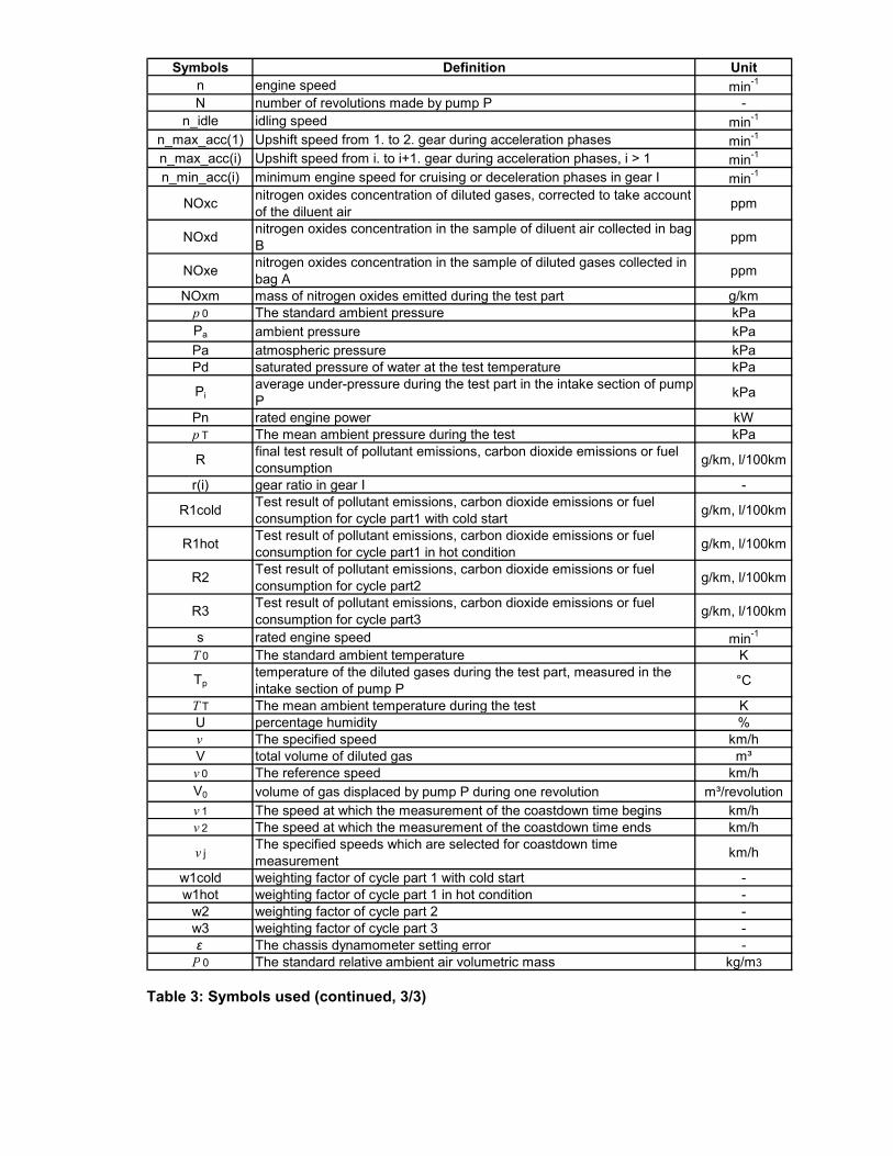
3.9 Symbols used The symbols used in this regulation are summarised in Table 1 to Table 3.
Xxxxx Standardise unit system
Symbols Definition Unita The coefficient of polygonal function -a T The rolling resistance force of front wheel Nb The coefficient of polygonal function -b T The coefficient of aerodynamic N/(km/h)2c The coefficient of polygonal function -
CCO Concentration of carbon monoxide vol-%CCOcorr corrected Concentration of carbon monoxide vol-%
CO2ccarbon dioxide concentration of diluted gases, corrected to take account of the diluent air %
CO2dcarbon dioxide concentration in the sample of diluent air collected in bag B %
CO2ecarbon dioxide concentration in the sample of diluted gases collected in bag A %
CO2m mass of carbon dioxide emitted during the test part g/km
COc carbon monoxide concentration of diluted gases, corrected to take account of the diluent air ppm
COd carbon monoxide concentration in the sample of diluent air collected in bag B ppm
COe carbon monoxide concentration in the sample of diluted gases collected in bag A ppm
COm mass of carbon monoxide emitted during the test part g/kmd 0 The standard ambient relative air density -
dCO density of the carbon monoxide at a temperature of 0°C and a pressure of 101,3 kPa kg/m³
dCO2density of the carbon dioxide at a temperature of 0°C and a pressure of 101,3 kPa kg/m³
DF dilution factor -
dHC density of the hydrocarbons at a temperature of 0°C and a pressure of 101,3 kPa kg/m³
dist distance driven in a cycle part km
dNOx density of the nitrogen oxides at a temperature of 0°C and a pressure of 101,3 kPa kg/m³
d T The relative air density under test conditions -∆ t The coastdown time s∆ t ai The coastdown time measured during the first road test s∆ t bi The coastdown time measured during the second road test s∆ T E The corrected coastdown time at the inertia mass (m i+m r1) s
∆ t EThe mean coastdown time on the chassis dynamometer at the reference speed s
∆ T i The average coastdown time at the specified speed s∆ t i The coastdown time corresponding to the reference speed s∆ T j The average coastdown time of the two tests s
∆ T road The target coastdown time sThe mean coastdown time on the chassis dynamometer without absorption s
∆ v The coastdown speed interval (2∆v =v 1-v 2) km/h
t∆
Table 1: Symbols used (1/3)
Symbols Definition UnitF The running resistance force NF * The target running resistance force N
F *(v 0) The target running resistance force at the reference speed on the chassis dynamometer N
F *(v i) The target running resistance force at the specified speed on the chassis dynamometer N
f *0 The corrected rolling resistance in the standard ambient conditions N
f *2The corrected coefficient of aerodynamic drag in the standard ambient conditions N/(km/h)2
F *j The target running resistance force at the specified speed Nf 0 The rolling resistance Nf 2 The coefficient of aerodynamic drag N/(km/h)2F E The set running resistance force on the chassis dynamometer N
F E(v 0) The set running resistance force at the reference speed on the chassis dynamometer N
F E(v i) The set running resistance force at the specified speed on the chassis dynamometer N
F f The total friction loss NF f(v 0) The total friction loss at the reference speed N
F j The running resistance force NF j(v 0) The running resistance force at the reference speed NF pau The braking force of the power absorbing unit N
F pau(v 0) The braking force of the power absorbing unit at the reference speed NF pau(v j) The braking force of the power absorbing unit at the specified speed N
F T The running resistance force obtained from the running resistance table N
H absolute humidity g/kg
HCc concentration of diluted gases, expressed in carbon equivalent, corrected to take account of the diluent air ppm
HCd concentration of hydrocarbons expressed in carbon equivalent, in the sample of diluent air collected in bag B ppm
HCe concentration of hydrocarbons expressed in carbon equivalent, in the sample of diluted gases collected in bag A ppm
HCm mass of hydrocarbons emitted during the test part g/kmK 0 The temperature correction factor for rolling resistance -Kh humidity correction factor -m The test motorcycle mass kgm a The actual mass of the test motorcycle kgm fi The flywheel equivalent inertia mass kgm i The equivalent inertia mass kgm k The motorcycle kerb mass kgmk kerb mass of the vehicle kgm r The equivalent inertia mass of all the wheels kg
m r1The equivalent inertia mass of the rear wheel and the motorcycle parts rotating with the wheel kg
m ref The motorcycle reference mass kgmref reference mass kgm rf The rotating mass of the front wheel kgm rid The rider mass kgmrid riders mass kg
Table 2: Symbols used (continued, 2/3)
Symbols Definition Unitn engine speed min-1
N number of revolutions made by pump P -n_idle idling speed min-1
n_max_acc(1) Upshift speed from 1. to 2. gear during acceleration phases min-1
n_max_acc(i) Upshift speed from i. to i+1. gear during acceleration phases, i > 1 min-1
n_min_acc(i) minimum engine speed for cruising or deceleration phases in gear I min-1
NOxc nitrogen oxides concentration of diluted gases, corrected to take account of the diluent air ppm
NOxd nitrogen oxides concentration in the sample of diluent air collected in bag B ppm
NOxe nitrogen oxides concentration in the sample of diluted gases collected in bag A ppm
NOxm mass of nitrogen oxides emitted during the test part g/kmp 0 The standard ambient pressure kPaPa ambient pressure kPaPa atmospheric pressure kPaPd saturated pressure of water at the test temperature kPa
Piaverage under-pressure during the test part in the intake section of pump P kPa
Pn rated engine power kWp T The mean ambient pressure during the test kPa
R final test result of pollutant emissions, carbon dioxide emissions or fuel consumption g/km, l/100km
r(i) gear ratio in gear I -
R1cold Test result of pollutant emissions, carbon dioxide emissions or fuel consumption for cycle part1 with cold start g/km, l/100km
R1hot Test result of pollutant emissions, carbon dioxide emissions or fuel consumption for cycle part1 in hot condition g/km, l/100km
R2 Test result of pollutant emissions, carbon dioxide emissions or fuel consumption for cycle part2 g/km, l/100km
R3 Test result of pollutant emissions, carbon dioxide emissions or fuel consumption for cycle part3 g/km, l/100km
s rated engine speed min-1
T 0 The standard ambient temperature K
Tptemperature of the diluted gases during the test part, measured in the intake section of pump P °C
T T The mean ambient temperature during the test KU percentage humidity %v The specified speed km/hV total volume of diluted gas m³v 0 The reference speed km/hV0 volume of gas displaced by pump P during one revolution m³/revolutionv 1 The speed at which the measurement of the coastdown time begins km/hv 2 The speed at which the measurement of the coastdown time ends km/h
v jThe specified speeds which are selected for coastdown time measurement km/h
w1cold weighting factor of cycle part 1 with cold start -w1hot weighting factor of cycle part 1 in hot condition -
w2 weighting factor of cycle part 2 -w3 weighting factor of cycle part 3 -ε The chassis dynamometer setting error -Ρ 0 The standard relative ambient air volumetric mass kg/m3
Table 3: Symbols used (continued, 3/3)
4 General Requirements The components liable to affect the emission of gaseous pollutants, carbon dioxide emissions and fuel consumption shall be so designed, constructed and assembled as to enable the vehicle in normal use, despite the vibration to which it may be subjected, to comply with the provisions of this Regulation.
5 [Performance Requirements] xxxxx decision of AC.3 required
6 Test Conditions 6.1 Test Vehicle
6.1.1 General The motorcycle shall conform in all its components with the production series, or, if the motorcycle is different from the production series, a full description shall be given in the test report.
6.1.2 Run-in The motorcycle must be presented in good mechanical condition. It must have been run in and driven at least 1 000 km before the test.
The engine, transmission and motorcycle shall be properly run in, in accordance with the manufacturer’s requirements.
6.1.3 Adjustments The motorcycle shall be adjusted in accordance with the manufacturer’s requirements, e.g. the viscosity of the oils, or, if the motorcycle is different from the production series, a full description shall be given in the test report.
6.1.4 Test Mass and Load Distribution The total test mass including the masses of the rider and the instruments shall be measured before the beginning of the tests.
The distribution of the load between the wheels shall be in conformity with the manufacturer’s instructions.
6.1.5 Tyres The tyres shall be of a type specified as original equipment by the vehicle manufacturer.
The tyre pressures shall be adjusted to the specifications of the manufacturer or to those where the speed of the motorcycle during the road test and the motorcycle speed obtained on the chassis dynamometer are equalized.
The tyre pressure shall be indicated in the test report.
6.2 [Vehicle Classification
6.2.1 Class 1 Vehicles that fulfil the following specifications belong to class 1:
Engine capacity <= 50 cm³ and 50 km/h < vmax < 60 km/h or
50 cm³ < Engine capacity < 150 cm³ and vmax <= 50 km/h or
Vehicles with engine capacity < 150 cm³ and vmax < 100 km/h.
vmax is the maximum vehicle speed.
6.2.2 Class 2 Vehicles that fulfil the following specifications belong to class 2:
Engine capacity < 150 cm³ and vmax >= 100 km/h or
Engine capacity >= 150 cm³ and vmax < 130 km/h.
vmax is the maximum vehicle speed.
6.2.3 Class 3 Vehicles with engine capacity >= 150 cm³ and vmax >= 130 km/h belong to class 3.
vmax is the maximum vehicle speed.]
6.3 Specification of Reference Fuel The appropriate reference fuels as defined in annex 10 to Regulation No. 83 must be used for testing.
For the purpose of calculation mentioned in paragraph 8.1.2.5, for petrol and diesel fuel the density measured at 15° C will be used.
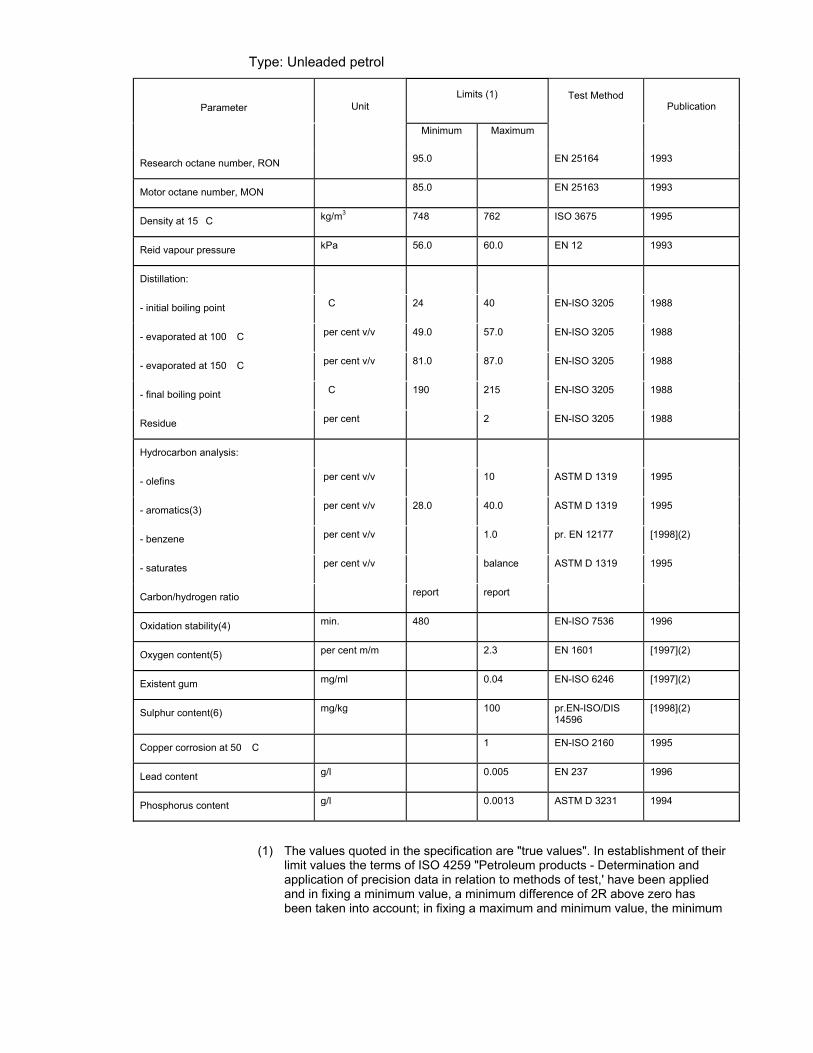
6.3.1 TECHNICAL DATA OF THE REFERENCE FUEL TO BE USED FOR TESTING VEHICLES EQUIPPED WITH POSITIVE-IGNITION ENGINES
Type: Unleaded petrol
Parameter
Unit
Limits (1)
Test Method
Publication
Minimum Maximum
Research octane number, RON 95.0 EN 25164 1993
Motor octane number, MON 85.0 EN 25163 1993
Density at 15�C kg/m3 748 762 ISO 3675 1995
Reid vapour pressure kPa 56.0 60.0 EN 12 1993
Distillation:
- initial boiling point �C 24 40 EN-ISO 3205 1988
- evaporated at 100 �C per cent v/v 49.0 57.0 EN-ISO 3205 1988
- evaporated at 150 �C per cent v/v 81.0 87.0 EN-ISO 3205 1988
- final boiling point �C 190 215 EN-ISO 3205 1988
Residue per cent 2 EN-ISO 3205 1988
Hydrocarbon analysis:
- olefins per cent v/v 10 ASTM D 1319 1995
- aromatics(3) per cent v/v 28.0 40.0 ASTM D 1319 1995
- benzene per cent v/v 1.0 pr. EN 12177 [1998](2)
- saturates per cent v/v balance ASTM D 1319 1995
Carbon/hydrogen ratio report report
Oxidation stability(4) min. 480 EN-ISO 7536 1996
Oxygen content(5) per cent m/m 2.3 EN 1601 [1997](2)
Existent gum mg/ml 0.04 EN-ISO 6246 [1997](2)
Sulphur content(6) mg/kg 100 pr.EN-ISO/DIS 14596
[1998](2)
Copper corrosion at 50 �C 1 EN-ISO 2160 1995
Lead content g/l 0.005 EN 237 1996
Phosphorus content g/l 0.0013 ASTM D 3231 1994
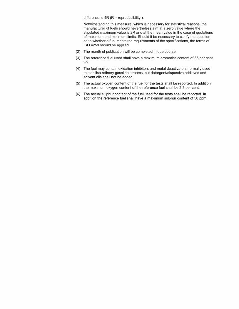
(1) The values quoted in the specification are "true values". In establishment of their limit values the terms of ISO 4259 "Petroleum products - Determination and application of precision data in relation to methods of test,' have been applied and in fixing a minimum value, a minimum difference of 2R above zero has been taken into account; in fixing a maximum and minimum value, the minimum
difference is 4R (R = reproducibility ).
Notwithstanding this measure, which is necessary for statistical reasons, the manufacturer of fuels should nevertheless aim at a zero value where the stipulated maximum value is 2R and at the mean value in the case of quotations of maximum and minimum limits. Should it be necessary to clarify the question as to whether a fuel meets the requirements of the specifications, the terms of ISO 4259 should be applied.
(2) The month of publication will be completed in due course.
(3) The reference fuel used shall have a maximum aromatics content of 35 per cent v/v.
(4) The fuel may contain oxidation inhibitors and metal deactivators normally used to stabilise refinery gasoline streams, but detergent/dispersive additives and solvent oils shall not be added.
(5) The actual oxygen content of the fuel for the tests shall be reported. In addition the maximum oxygen content of the reference fuel shall be 2.3 per cent.
(6) The actual sulphur content of the fuel used for the tests shall be reported. In addition the reference fuel shall have a maximum sulphur content of 50 ppm.
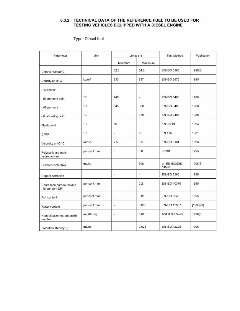
6.3.2 TECHNICAL DATA OF THE REFERENCE FUEL TO BE USED FOR TESTING VEHICLES EQUIPPED WITH A DIESEL ENGINE
Type: Diesel fuel
Limits (1)
Parameter
Unit
Minimum
Maximum
Test Method
Publication
Cetane number(2)
52.0
54.0
EN-ISO 5165
1998(3) Density at 15°C
kg/m³
833
837
EN-ISO 3675
1995 Distillation:
- 50 per cent point
°C
245
-
EN-ISO 3405
1988 - 95 per cent
°C
345
350
EN-ISO 3405
1988 - final boiling point
°C
-
370
EN-ISO 3405
1988 Flash point
°C
55
-
EN 22719
1993 CFPP
°C
-
-5
EN 116
1981 Viscosity at 40 °C
mm²/s
2.5
3.5
EN-ISO 3104
1996 Polycyclic aromatic hydrocarbons
per cent m/m
3
6.0
IP 391
1995 Sulphur content(4)
mg/kg
-
300
pr. EN-ISO/DIS 14596
1998(3) Copper corrosion
-
1
EN-ISO 2160
1995 Conradson carbon residue (10 per cent DR)
per cent m/m
-
0.2
EN-ISO 10370
1995 Ash content
per cent m/m
-
0.01
EN-ISO 6245
1995 Water content
per cent m/m
-
0.05
EN-ISO 12937
[1998](3) Neutralisation (strong acid) number
mg KOH/g
-
0,02
ASTM D 974-95
1998(3) Oxidation stability(5)
mg/ml
-
0.025
EN-ISO 12205
1996
TRANS/WP.29/xxx
page 2
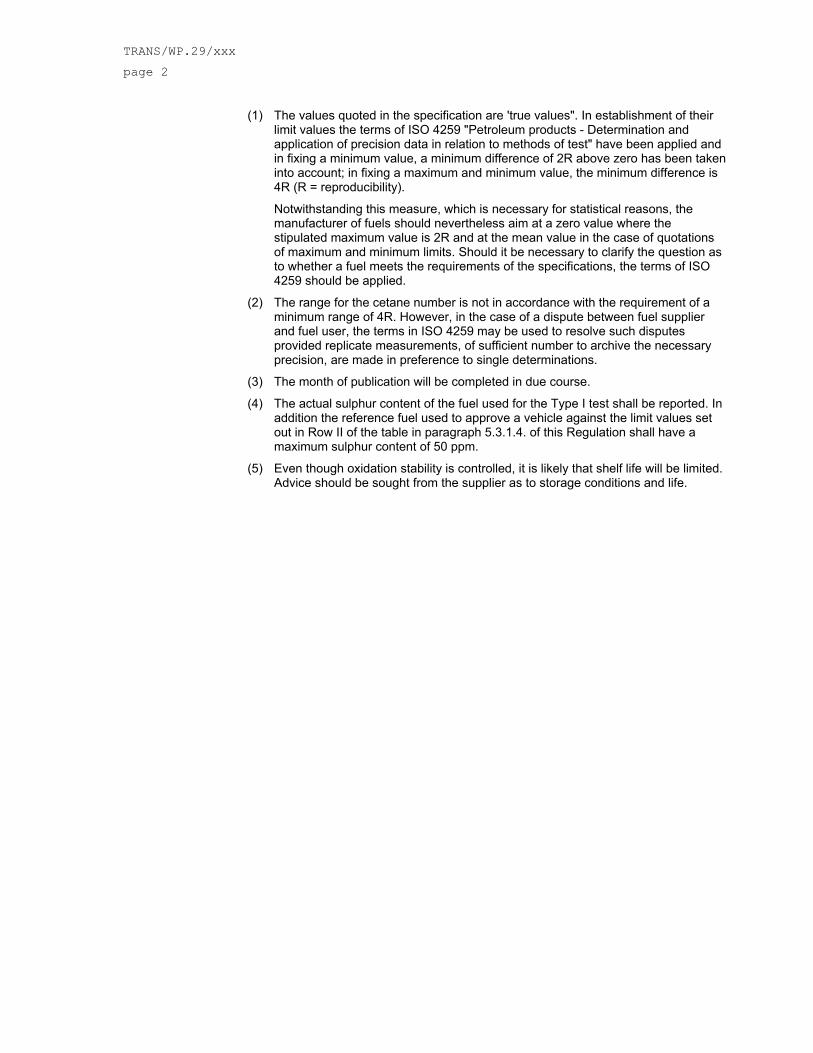
(1) The values quoted in the specification are 'true values". In establishment of their limit values the terms of ISO 4259 "Petroleum products - Determination and application of precision data in relation to methods of test" have been applied and in fixing a minimum value, a minimum difference of 2R above zero has been taken into account; in fixing a maximum and minimum value, the minimum difference is 4R (R = reproducibility).
Notwithstanding this measure, which is necessary for statistical reasons, the manufacturer of fuels should nevertheless aim at a zero value where the stipulated maximum value is 2R and at the mean value in the case of quotations of maximum and minimum limits. Should it be necessary to clarify the question as to whether a fuel meets the requirements of the specifications, the terms of ISO 4259 should be applied.
(2) The range for the cetane number is not in accordance with the requirement of a minimum range of 4R. However, in the case of a dispute between fuel supplier and fuel user, the terms in ISO 4259 may be used to resolve such disputes provided replicate measurements, of sufficient number to archive the necessary precision, are made in preference to single determinations.
(3) The month of publication will be completed in due course.
(4) The actual sulphur content of the fuel used for the Type I test shall be reported. In addition the reference fuel used to approve a vehicle against the limit values set out in Row II of the table in paragraph 5.3.1.4. of this Regulation shall have a maximum sulphur content of 50 ppm.
(5) Even though oxidation stability is controlled, it is likely that shelf life will be limited. Advice should be sought from the supplier as to storage conditions and life.
TRANS/WP.29/xxx
page 2
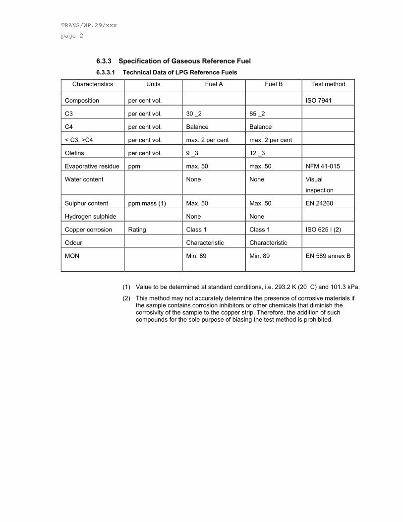
6.3.3 Specification of Gaseous Reference Fuel 6.3.3.1 Technical Data of LPG Reference Fuels
Characteristics Units Fuel A Fuel B Test method Composition
per cent vol.
ISO 7941
C3 per cent vol.
30 _2
85 _2
C4 per cent vol.
Balance
Balance
< C3, >C4 per cent vol.
max. 2 per cent
max. 2 per cent
Olefins per cent vol.
9 _3
12 _3
Evaporative residue ppm
max. 50
max. 50
NFM 41-015
Water content
None
None
Visual
inspection Sulphur content
ppm mass (1)
Max. 50
Max. 50
EN 24260
Hydrogen sulphide
None
None
Copper corrosion Rating
Class 1
Class 1
ISO 625 I (2)
Odour
Characteristic
Characteristic
MON
Min. 89
Min. 89
EN 589 annex B
(1) Value to be determined at standard conditions, i.e. 293.2 K (20 C) and 101.3 kPa.
(2) This method may not accurately determine the presence of corrosive materials if the sample contains corrosion inhibitors or other chemicals that diminish the corrosivity of the sample to the copper strip. Therefore, the addition of such compounds for the sole purpose of biasing the test method is prohibited.
TRANS/WP.29/xxx
page 3
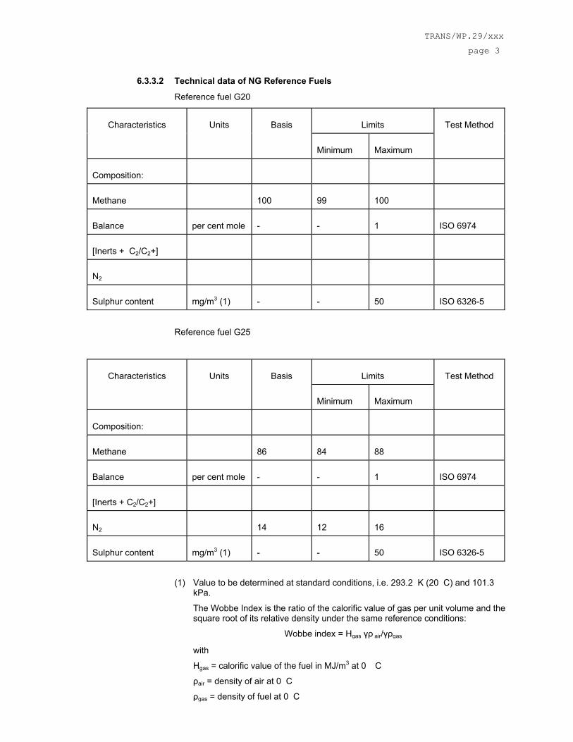
6.3.3.2 Technical data of NG Reference Fuels
Reference fuel G20
Limits
Characteristics
Units
Basis
Minimum
Maximum
Test Method
Composition:
Methane
100
99
100
Balance
per cent mole
-
-
1
ISO 6974
[Inerts + C2/C2+]
N2
Sulphur content
mg/m3 (1)
-
-
50
ISO 6326-5
Reference fuel G25
Limits
Characteristics
Units
Basis
Minimum
Maximum
Test Method
Composition:
Methane
86
84
88
Balance
per cent mole
-
-
1
ISO 6974
[Inerts + C2/C2+]
N2
14
12
16
Sulphur content
mg/m3 (1)
-
-
50
ISO 6326-5
(1) Value to be determined at standard conditions, i.e. 293.2 K (20 C) and 101.3 kPa.
The Wobbe Index is the ratio of the calorific value of gas per unit volume and the square root of its relative density under the same reference conditions:
Wobbe index = Hgas γρ air/γρgas
with
Hgas = calorific value of the fuel in MJ/m3 at 0 �C
ρair = density of air at 0 C
ρgas = density of fuel at 0 C
page 4
The Wobbe Index is said to be gross or net according to whether the calorific value is the gross or net calorific value.
6.4 Type I Tests
6.4.1 Rider The rider shall have a mass of 75 kg ± 5 kg.
6.4.2 Test Bench Specifications and Settings 6.4.2.1 The dynamometer shall have a single roll with a diameter of at least 0,400 m. 6.4.2.2 The dynamometer shall be equipped with a roll revolution counter for measuring
actual distance travelled. 6.4.2.3 Flywheels or other means shall be used to stimulate the inertia specified in 7.2.2. 6.4.2.4 Cooling fan specifications as follows:
6.4.2.4.1 Throughout the test, a variable speed cooling blower shall be positioned in front of the motorcycle, so as to direct the cooling air to the motorcycle in a manner, which simulates actual operating conditions. The blower speed shall be such that, within the operating range of 10 to 50 km/h, the linear velocity of the air at the blower outlet is within ±5 km/h of the corresponding roller speed. And at the range of over 50 km/h, the linear velocity of the air shall be within ±10%. At roller speeds of less than 10 km/h, air velocity may be zero.
6.4.2.4.2 The above mentioned air velocity shall be determined as an averaged value of 9 measuring points which are located at the centre of each rectangle dividing whole of the blower outlet into 9 areas (dividing both of horizontal and vertical sides of the blower outlet into 3 equal parts). Each value at those 9 points shall be within 10% of the averaged value of themselves.
6.4.2.4.3 The blower outlet shall have a cross section area of at least 0,4 m2 and the bottom of the blower outlet shall be between 5 and 20 cm above floor level. The blower outlet shall be perpendicular to the longitudinal axis of the motorcycle between 30 and 45 cm in front of its front wheel. The device used to measure the linear velocity of the air shall be located at between 0 and 20 cm from the air outlet.
6.4.2.5 The chassis dynamometer rollers shall be clean, dry and free from anything, which might cause the tyre to slip.
TRANS/WP.29/xxx
page 5
6.4.3 Exhaust Gas Measurement System Xxxxx Drawings have to be added.
6.4.3.1 The gas-collection device shall be a closed type device that can collect all exhaust gases at the motorcycle exhaust outlet(s) on condition that it satisfies the back pressure condition of ±125 mm H2O. An open system may be used as well if it is confirmed that all the exhaust gases are collected. The gas collection shall be such that there is no condensation, which could appreciably modify that nature of exhaust gases at the test temperature.
6.4.3.2 A connecting tube between the device and the exhaust gas sampling system. This tube, and the device shall be made of stainless steel, or of some other material, which does not affect the composition of the gases collected, and which withstands the temperature of these gases.
6.4.3.3 A heat exchanger capable of limiting the temperature variation of the diluted gases in the pump intake to ±5 °C throughout the test. This exchanger shall be equipped with a preheating system able to bring the exchanger to its operating temperature (with the tolerance of ±5 °C) before the test begins.
6.4.3.4 A positive displacement pump to draw in the dilute exhaust mixture. This pump is equipped with a motor having several strictly controlled uniform speeds. The pump capacity shall be large enough to ensure the intake of the exhaust gases. A device using a critical flow Venturi may also be used.
6.4.3.5 A device to allow continuous recording of the diluted exhaust mixture entering the pump.
6.4.3.6 Two gauges; the first to ensure the pressure depression of the dilute exhaust mixture entering the pump, relative to atmospheric pressure, the other to measure the dynamic pressure variation of the positive displacement pump.
6.4.3.7 A probe located near to, but outside the gas-collecting device, to collect, through a pump, a filter and a flow meter, samples of the dilution air stream, at constant flow rates throughout the test.
6.4.3.8 A sample probe pointed upstream into the dilute exhaust mixture flow, upstream of the positive displacement pump to collect, through a pump, a filter and a flow meter, samples of the dilute exhaust mixture, at constant flow rates, throughout the test. The minimum sample flow rate in the two sampling devices described above and in 6.4.3.7 shall be at least 150 l/h.
6.4.3.9 Three way valves on the sampling system described in 6.4.3.7 and 6.4.3.8 to direct the samples either to their respective bags or to the outside throughout the test.
6.4.3.10 Gas-tight collection bags for dilution air and dilute exhaust mixture of sufficient capacity so as not to impede normal sample flow and which will not change the nature of the pollutants concerned.
6.4.3.11 The bags shall have an automatic self-locking device and shall be easily and tightly fastened either to the sampling system or the analysing system at the end of the test.
6.4.3.12 A revolution counter to count the revolutions of the positive displacement pump throughout the test.
NOTE 1 Good care shall be taken on the connecting method and the material or configuration of the connecting parts because there is a possibility that each section (e.g. the adapter and the coupler) of the sampling system becomes very hot. It the measurement cannot be performed normally due to heat-damages of the sampling system, an auxiliary cooling device may be used as long as the exhaust gases are not affected.
NOTE 2 Open type devices have risks of incomplete gas collection and gas leakage into the test cell. It is necessary to make sure there is no leakage throughout the sampling period.
page 6
NOTE 3 If a constant CVS flow rate is used throughout the test cycle that includes low and high speeds all in one (i.e. Part 1, 2 and 3 cycles of WMTC validation test step 2 mode), special attention should be paid because of higher risk of water condensation in high speed range.
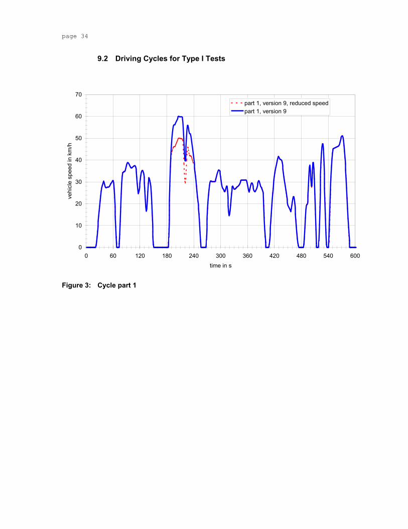
6.4.4 Driving Schedules 6.4.4.1 Test Cycles
The test cycle for the type I test consists of up to three parts. Depending on the vehicle class (see paragraph 6.2) the following parts have to be run:
Vehicle class 1: part 1, reduced speed in cold condition followed by part 1, reduced speed in hot condition, if
Engine capacity <= 50 cm³ and 50 km/h < vmax < 60 km/h or
50 cm³ < Engine capacity < 150 cm³ and vmax <= 50 km/h.
part 1 in cold condition followed by part 1 in hot condition, if
vmax >= 60 km/h
vmax is the maximum vehicle speed.
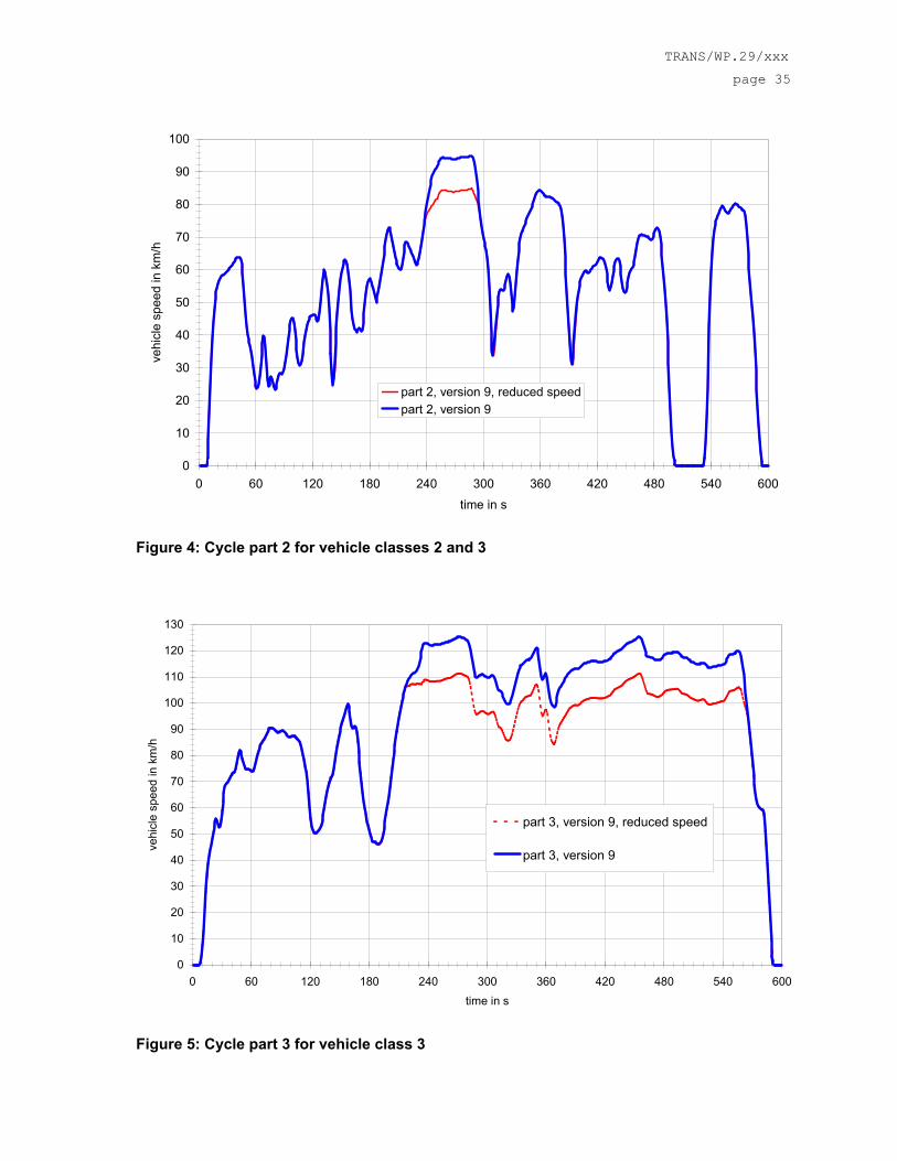
Vehicle class 2: part 1 in cold condition followed by part 2, reduced speed in hot condition, if
vmax < 115 km/h
part 1 in cold condition followed by part 2 in hot condition, if
vmax >= 115 km/h
vmax is the maximum vehicle speed.
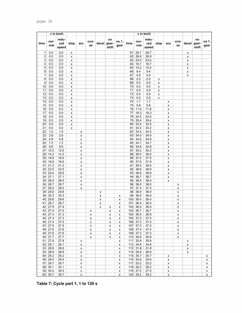
Vehicle class 3: part 1 in cold condition followed by part 2 and part 3, reduced speed in hot condition, if
vmax < 140 km/h
part 1 in cold condition followed by part 2 and part 3 in hot condition, if
vmax >= 140 km/h
vmax is the maximum vehicle speed.
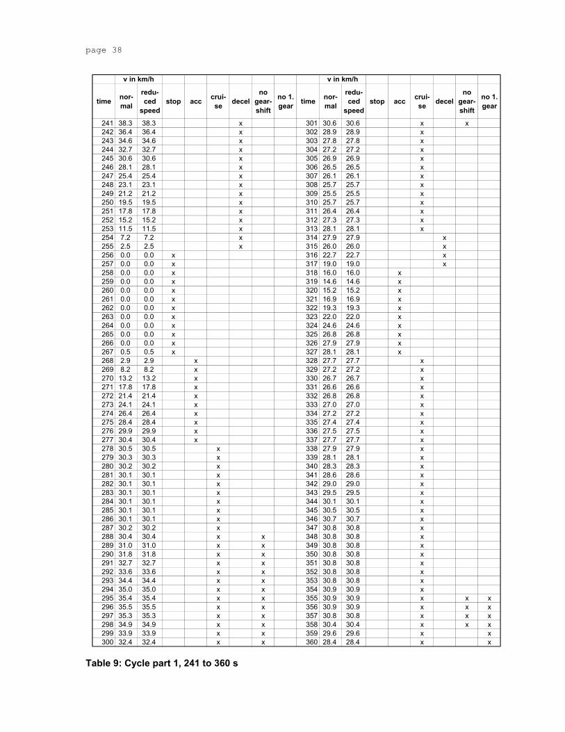
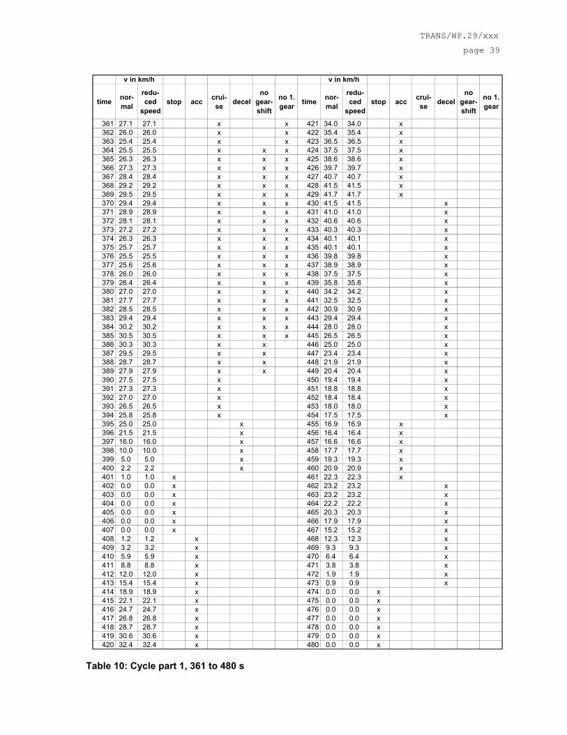
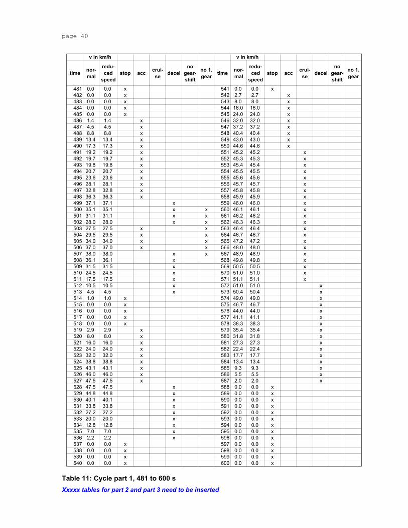
The vehicle speed pattern is shown in annex 9.2.
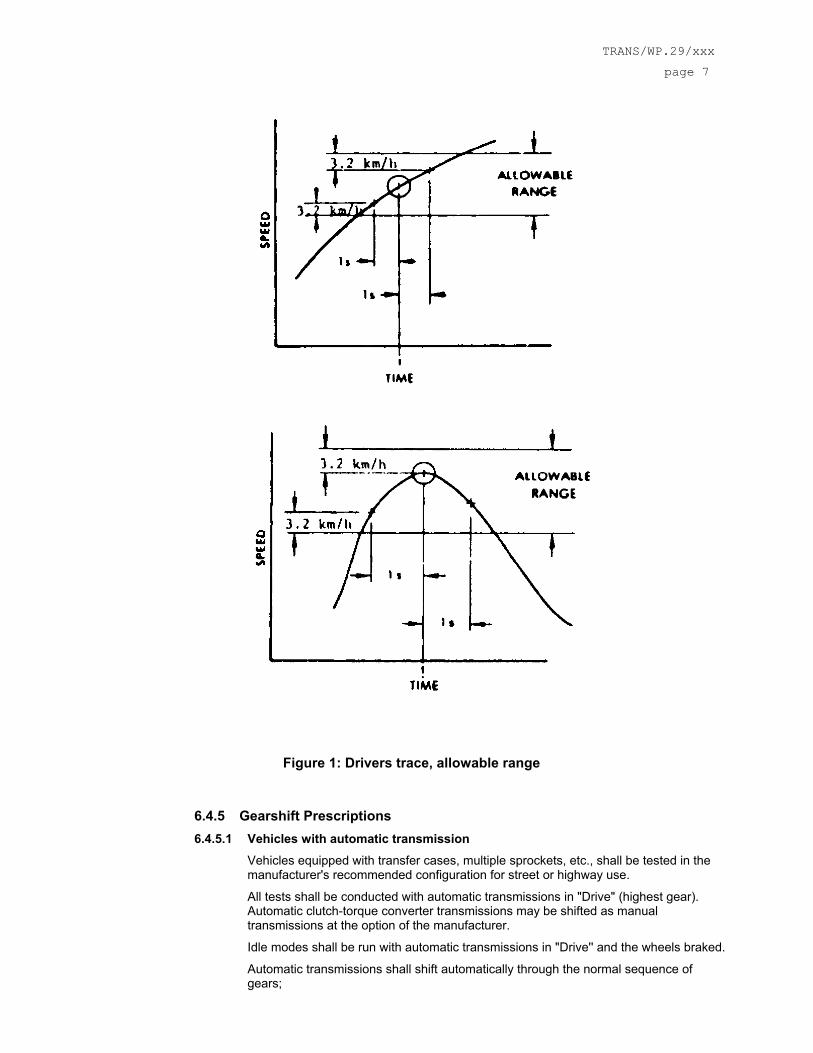
6.4.4.2 Speed Tolerances The speed tolerance at any given time on the test cycle prescribed in 6.4.4.1 is defined by upper and lower limits. The upper limit is 3,2 km/h higher than the highest point on the trace within 1 second of the given time. The lower limit is 3,2 km/h lower than the lowest point on the trace within 1 second of the given time. Speed variations greater than the tolerances (such as may occur during gear changes) are acceptable provided they occur for less than 2 seconds on any occasion. Speeds lower than those prescribed are acceptable provided the vehicle is operated at maximum available power during such occurrences. Figure 1 shows the range of acceptable speed tolerances for typical points.
TRANS/WP.29/xxx
page 7
Figure 1: Drivers trace, allowable range
6.4.5 Gearshift Prescriptions 6.4.5.1 Vehicles with automatic transmission
Vehicles equipped with transfer cases, multiple sprockets, etc., shall be tested in the manufacturer's recommended configuration for street or highway use.
All tests shall be conducted with automatic transmissions in "Drive" (highest gear). Automatic clutch-torque converter transmissions may be shifted as manual transmissions at the option of the manufacturer.
Idle modes shall be run with automatic transmissions in "Drive'' and the wheels braked.
Automatic transmissions shall shift automatically through the normal sequence of gears;
page 8
The deceleration modes shall be run in gear using brakes or throttle as necessary to maintain the desired speed.
6.4.5.2 Vehicles with manual transmission Idle modes shall be run with manual transmissions in 1. gear with the clutch disengaged.
For acceleration phases manual transmissions shall be shifted from 1. to 2. gear when the engine speed reaches a value according to the following formula:
n_max_acc(1) = (0,5753*exp(-1,9*(Pn/(mk + 75 kg)) - 0,10)*(s - n_idle) + n_idle equation 1 Pn - rated power in kW
mk – kerb mass in kg n – engine speed in min-1 n_idle – idling speed in min-1 s - rated engine speed in min-1
Upshifts for higher gears have to be carried out during acceleration phases when the engine speed reaches a value according to the following formula:
n_max_acc(i) = (0, 5753*exp(-1,9*(Pn/(mk + 75 kg)))*(s - n_idle) + n_idle equation 2 Pn - rated power in kW
mk – kerb mass in kg n – engine speed in min-1 n_idle – idling speed in min-1 s - rated engine speed in min-1 at max. power i – gear number (>= 2)
The minimum engine speeds for acceleration phases in gear 2 or higher gears are accordingly defined by the following formula:
n_min_acc(i) = n_max_acc(i-1)*r(i)/r(i-1) equation 3 r(i) – ratio of gear i
The minimum engine speeds for deceleration phases or cruising phases in gear 2 or higher gears are defined by the following formula:
n_min_dec(i) = n_min_acc(i-1)*r(i)/r(i-1) equation 4 r(i) – ratio of gear I
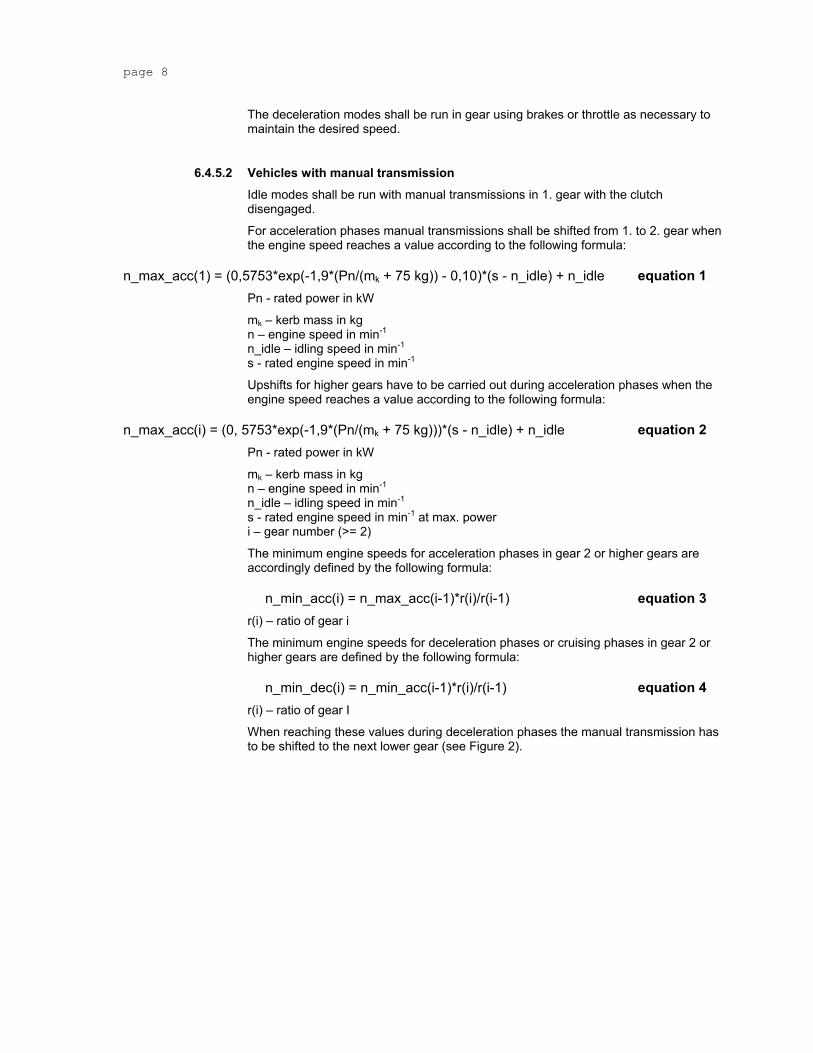
When reaching these values during deceleration phases the manual transmission has to be shifted to the next lower gear (see Figure 2).
There are fixed allocations for acceleration, cruising and deceleration phases (see annex 9.2)
Gearshifts are prohibited for indicated cycle sections (see annex 9.2)
Downshifts to the 1. gear are prohibited for those modes, which require the vehicle to decelerate to zero.
Manual transmissions gearshifts shall be accomplished with minimum time with the operator closing the throttle during each shift.
The 1. gear should only be used when starting from standstill.
For those modes that require the vehicle to decelerate to zero, manual transmission clutches shall be disengaged when the speed drops below 10 km/h, when the engine speed reaches idling speed, when engine roughness is evident, or when engine stalling is imminent.
While the clutch is disengaged the vehicle shall be shifted to the appropriate gear for starting the next mode.
In general it is allowed to use higher shift speeds than derived from the formulas above.
Xxxxx add a more clear description of the procedure, flowchart.
6.4.6 Dynamometer Settings A full description of the chassis dynamometer and instruments shall be provided in accordance with annex 9.3
Measurements shall be made to the accuracies as specified in paragraph 6.4.7, Table 5.
The running resistance force for the chassis dynamometer settings can be derived either from on road cost down measurements or from a running resistance table.
page 10
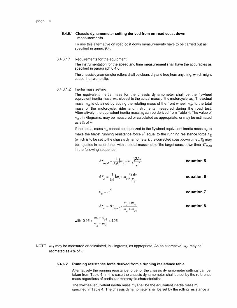
6.4.6.1 Chassis dynamometer setting derived from on-road coast down measurements
To use this alternative on road cost down measurements have to be carried out as specified in annex 9.4.
6.4.6.1.1 Requirements for the equipment The instrumentation for the speed and time measurement shall have the accuracies as specified in paragraph 6.4.6.
The chassis dynamometer rollers shall be clean, dry and free from anything, which might cause the tyre to slip.
6.4.6.1.2 Inertia mass setting The equivalent inertia mass for the chassis dynamometer shall be the flywheel equivalent inertia mass, mfi, closest to the actual mass of the motorcycle, ma. The actual mass, ma, is obtained by adding the rotating mass of the front wheel, mrf, to the total mass of the motorcycle, rider and instruments measured during the road test. Alternatively, the equivalent inertia mass mi can be derived from Table 4. The value of mrf , in kilograms, may be measured or calculated as appropriate, or may be estimated as 3% of m.
If the actual mass ma cannot be equalized to the flywheel equivalent inertia mass mi, to make the target running resistance force F* equal to the running resistance force FE (which is to be set to the chassis dynamometer), the corrected coast down time ∆TE may be adjusted in accordance with the total mass ratio of the target coast down time ∆Troad in the following sequence:
( ) *raroad F
vmm,
T ∆∆ 263
11+= equation 5
( )E
riE Fvmm
,T ∆∆ 2
631
1+= equation 6
*E FF = equation 7
1
1
ra
riroadE mm
mmTT
+
+×= ∆∆ equation 8
with 0519501
1 ,mm
mm,
ra
ri <+
+<
NOTE mr1 may be measured or calculated, in kilograms, as appropriate. As an alternative, mr1 may be estimated as 4% of m.
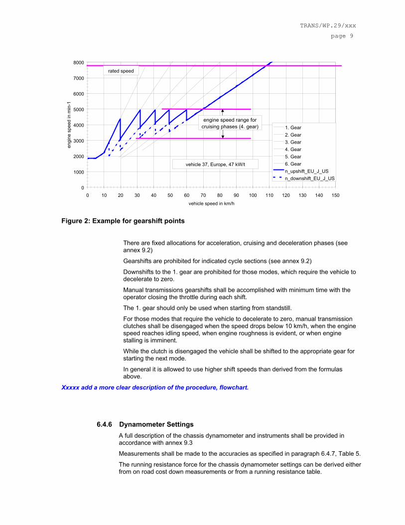
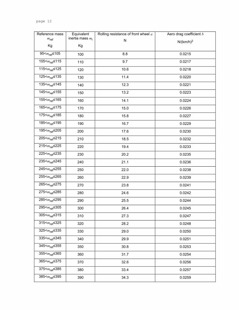
6.4.6.2 Running resistance force derived from a running resistance table Alternatively the running resistance force for the chassis dynamometer settings can be taken from Table 4. In this case the chassis dynamometer shall be set by the reference mass regardless of particular motorcycle characteristics.
The flywheel equivalent inertia mass mfi shall be the equivalent inertia mass mi specified in Table 4. The chassis dynamometer shall be set by the rolling resistance a
TRANS/WP.29/xxx
page 11
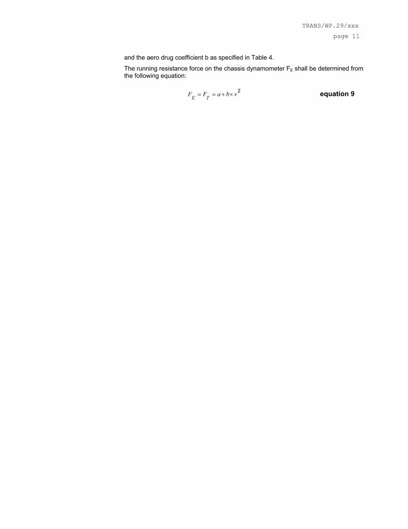
and the aero drug coefficient b as specified in Table 4.
The running resistance force on the chassis dynamometer FE shall be determined from the following equation:
2vbaFF TE ×+== equation 9
page 12
Reference mass mref
Kg
Equivalent inertia mass mi
Kg
Rolling resistance of front wheel a
N
Aero drag coefficient b
N/(km/h)2
95<mref≤105 100 8.8 0.0215
105<mref≤115 110 9.7 0.0217
115<mref≤125 120 10.6 0.0218
125<mref≤135 130 11.4 0.0220
135<mref≤145 140 12.3 0.0221
145<mref≤155 150 13.2 0.0223
155<mref≤165 160 14.1 0.0224
165<mref≤175 170 15.0 0.0226
175<mref≤185 180 15.8 0.0227
185<mref≤195 190 16.7 0.0229
195<mref≤205 200 17.6 0.0230
205<mref≤215 210 18.5 0.0232
215<mref≤225 220 19.4 0.0233
225<mref≤235 230 20.2 0.0235
235<mref≤245 240 21.1 0.0236
245<mref≤255 250 22.0 0.0238
255<mref≤265 260 22.9 0.0239
265<mref≤275 270 23.8 0.0241
275<mref≤285 280 24.6 0.0242
285<mref≤295 290 25.5 0.0244
295<mref≤305 300 26.4 0.0245
305<mref≤315 310 27.3 0.0247
315<mref≤325 320 28.2 0.0248
325<mref≤335 330 29.0 0.0250
335<mref≤345 340 29.9 0.0251
345<mref≤355 350 30.8 0.0253
355<mref≤365 360 31.7 0.0254
365<mref≤375 370 32.6 0.0256
375<mref≤385 380 33.4 0.0257
385<mref≤395 390 34.3 0.0259
TRANS/WP.29/xxx
page 13
Reference mass mref
Kg
Equivalent inertia mass mi
Kg
Rolling resistance of front wheel a
N
Aero drag coefficient b
N/(km/h)2
395<mref≤405 400 35.2 0.0260
405<mref≤415 410 36.1 0.0262
415<mref≤425 420 37.0 0.0263
425<mref≤435 430 37.8 0.0265
435<mref≤445 440 38.7 0.0266
445<mref≤455 450 39.6 0.0268
455<mref≤465 460 40.5 0.0269
465<mref≤475 470 41.4 0.0271
475<mref≤485 480 42.2 0.0272
485<mref≤495 490 43.1 0.0274
495<mref≤505 500 44.0 0.0275
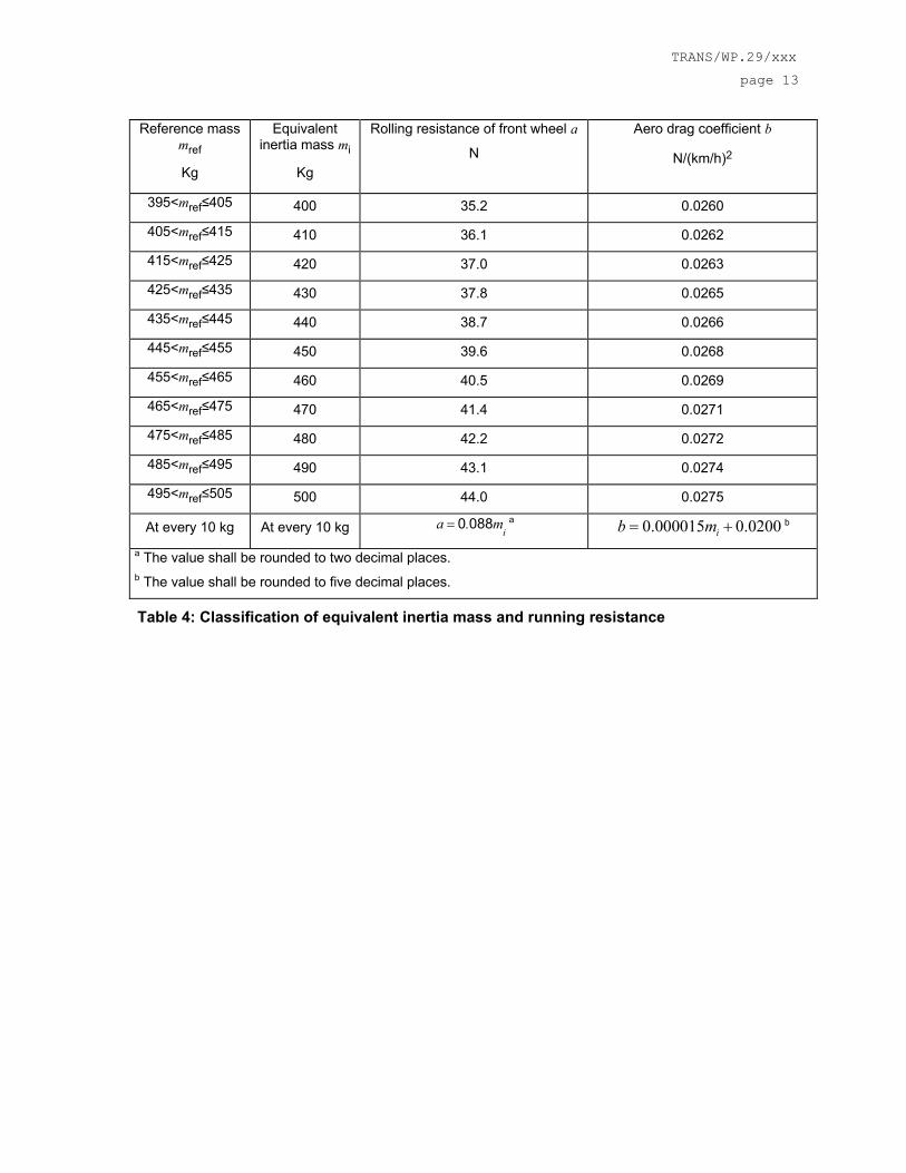
At every 10 kg At every 10 kg im.a 0880= a 0.000015 0.0200ib m= + b
a The value shall be rounded to two decimal places. b The value shall be rounded to five decimal places.
Table 4: Classification of equivalent inertia mass and running resistance
page 14
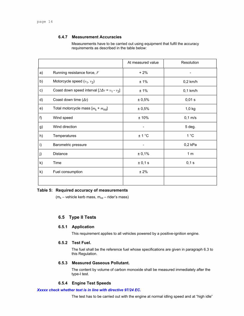
6.4.7 Measurement Accuracies Measurements have to be carried out using equipment that fulfil the accuracy requirements as described in the table below:
At measured value Resolution
a) Running resistance force, F + 2% -
b) Motorcycle speed (v1, v2) ± 1% 0,2 km/h
c) Coast down speed interval [2∆v = v1 - v2] ± 1% 0,1 km/h
d) Coast down time (∆t) ± 0,5% 0,01 s
e) Total motorcycle mass [mk + mrid] ± 0,5% 1,0 kg
6.5.1 Application This requirement applies to all vehicles powered by a positive-ignition engine.
6.5.2 Test Fuel. The fuel shall be the reference fuel whose specifications are given in paragraph 6.3 to this Regulation.
6.5.3 Measured Gaseous Pollutant. The content by volume of carbon monoxide shall be measured immediately after the type-I test.
6.5.4 Engine Test Speeds Xxxxx check whether text is in line with directive 97/24 EC.
The test has to be carried out with the engine at normal idling speed and at “high idle”
TRANS/WP.29/xxx
page 15
speed.
High idle speed is defined as 2000 min-1, if dual normal idling speed is equal or below 2000 min-1, or as dual normal idling speed, if this value is higher than 2000 min-1.
6.5.5 Gear Lever Position In the case of vehicles with manually operated or semi-automatic shift gearboxes, the test shall be carried out with the gear lever in the "neutral" position and with the clutch engaged.
In the case of vehicles with automatic-shift gearboxes, the test shall be carried out with the gear selector in either the "zero" or the "park” position.
7 Test Procedures 7.1 Description of Tests.
The vehicle shall be subjected, according to its category, to tests of two types, I and II, as specified below.
7.1.1 Type-I Test (verifying the average emission of gaseous pollutants, CO2 emissions and fuel consumption in a characteristic driving cycle).
7.1.1.1 The test shall be carried out by the method described in paragraph 7.1 to this Regulation. The gases shall be collected and analysed by the prescribed methods.
7.1.1.2 Subject to the provisions of paragraph 7.1 below, the test shall be repeated three times. In each test, the mass of the carbon monoxide, the mass of the hydrocarbons, the mass of the nitrogen oxides, the mass of carbon dioxide and the mass of the fuel, consumed during the test shall be determined.
7.1.2 Type-II Test (test of carbon monoxide at idling speed) and emissions data required for roadworthiness testing.
The carbon monoxide content of the exhaust gases emitted shall be checked by a test with the engine at normal idling speed and at “high idle” speed (i.e. > 2000 min-1) carried out by the method described in paragraph 7.3 to this Regulation.
7.2 Type I Tests
7.2.1 Overview The type I test consists of prescribed sequences of dynamometer preparation, fuelling, parking, and operating conditions.
The test is designed to determine hydrocarbon, carbon monoxide, oxides of nitrogen, carbon dioxide mass emissions and fuel consumption while simulating real world operation. The test consists of engine start-ups and motorcycle operation on a chassis dynamometer, through a specified driving cycle. A proportional part of the diluted exhaust emissions is collected continuously for subsequent analysis, using a constant volume (variable dilution) sampler.
Except in cases of component malfunction or failure, all emission control systems installed on or incorporated in a new motorcycle shall be functioning during all procedures.
Background concentrations are measured for all species for which emissions measurements are made. For exhaust testing, this requires sampling and analysis of the dilution air.
page 16
7.2.2 Dynamometer Settings and Verification 7.2.2.1 Vehicle Preparation
The manufacturer shall provide additional fittings and adapters, as required to accommodate a fuel drain at the lowest point possible in the tank(s) as installed on the vehicle and to provide for exhaust sample collection.
The tyre pressures shall be adjusted to the specifications of the manufacturer or to those at which the speed of the motorcycle during the road test and the motorcycle speed obtained on the chassis dynamometer are equal.
The test motorcycle shall be warmed up on the chassis dynamometer.
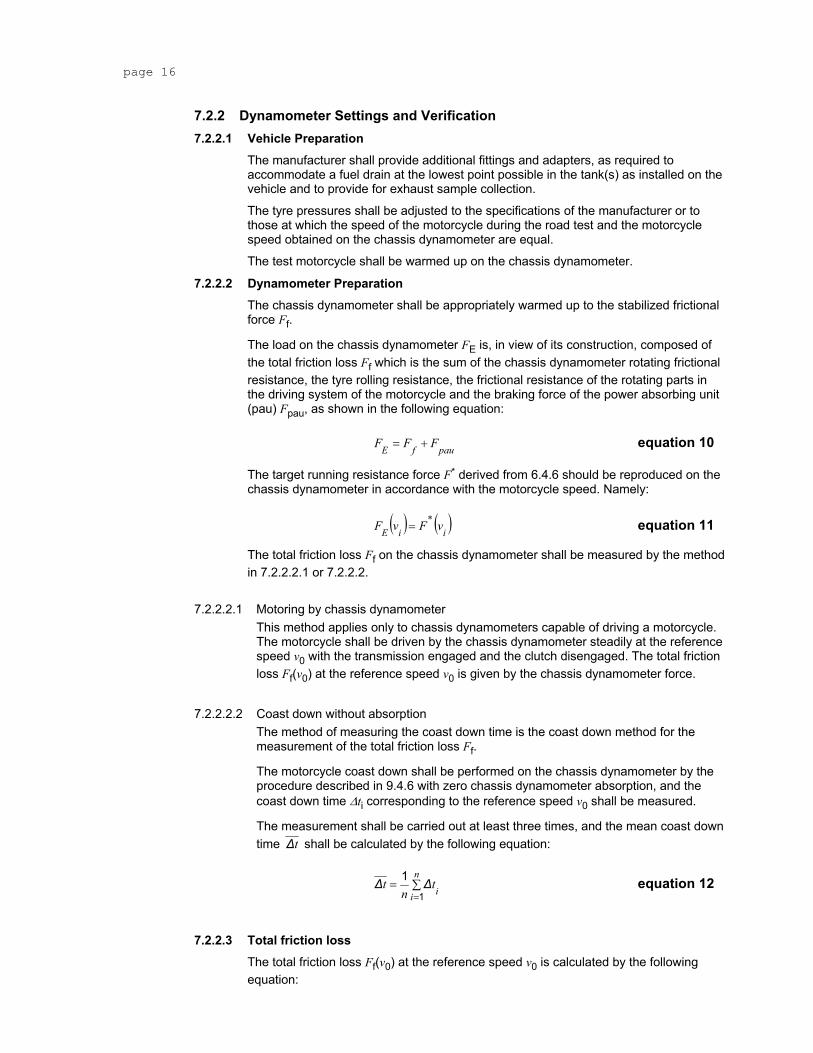
7.2.2.2 Dynamometer Preparation The chassis dynamometer shall be appropriately warmed up to the stabilized frictional force Ff.
The load on the chassis dynamometer FE is, in view of its construction, composed of the total friction loss Ff which is the sum of the chassis dynamometer rotating frictional resistance, the tyre rolling resistance, the frictional resistance of the rotating parts in the driving system of the motorcycle and the braking force of the power absorbing unit (pau) Fpau, as shown in the following equation:
paufE FFF += equation 10
The target running resistance force F* derived from 6.4.6 should be reproduced on the chassis dynamometer in accordance with the motorcycle speed. Namely:
( ) ( )i*
iE vFvF = equation 11
The total friction loss Ff on the chassis dynamometer shall be measured by the method in 7.2.2.2.1 or 7.2.2.2.
7.2.2.2.1 Motoring by chassis dynamometer This method applies only to chassis dynamometers capable of driving a motorcycle. The motorcycle shall be driven by the chassis dynamometer steadily at the reference speed v0 with the transmission engaged and the clutch disengaged. The total friction loss Ff(v0) at the reference speed v0 is given by the chassis dynamometer force.
7.2.2.2.2 Coast down without absorption The method of measuring the coast down time is the coast down method for the measurement of the total friction loss Ff.
The motorcycle coast down shall be performed on the chassis dynamometer by the procedure described in 9.4.6 with zero chassis dynamometer absorption, and the coast down time ∆ti corresponding to the reference speed v0 shall be measured.
The measurement shall be carried out at least three times, and the mean coast down time t∆ shall be calculated by the following equation:
∑==
n
i itnt
1
1 ∆∆ equation 12
7.2.2.3 Total friction loss The total friction loss Ff(v0) at the reference speed v0 is calculated by the following equation:
TRANS/WP.29/xxx
page 17
( ) ( )tvmm
,vF rif ∆
∆263
110 += equation 13
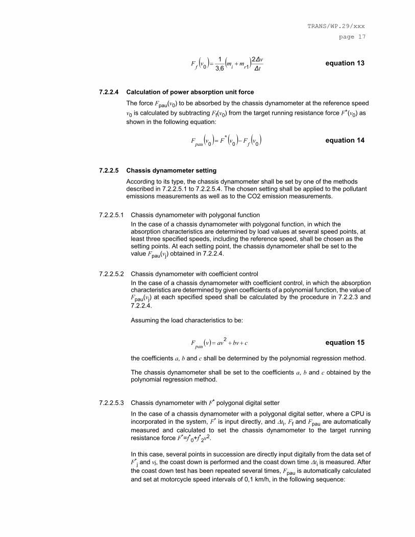
7.2.2.4 Calculation of power absorption unit force The force Fpau(v0) to be absorbed by the chassis dynamometer at the reference speed v0 is calculated by subtracting Ff(v0) from the target running resistance force F*(v0) as shown in the following equation:
( ) ( ) ( )000 vFvFvF f*
pau −= equation 14
7.2.2.5 Chassis dynamometer setting According to its type, the chassis dynamometer shall be set by one of the methods described in 7.2.2.5.1 to 7.2.2.5.4. The chosen setting shall be applied to the pollutant emissions measurements as well as to the CO2 emission measurements.
7.2.2.5.1 Chassis dynamometer with polygonal function In the case of a chassis dynamometer with polygonal function, in which the absorption characteristics are determined by load values at several speed points, at least three specified speeds, including the reference speed, shall be chosen as the setting points. At each setting point, the chassis dynamometer shall be set to the value Fpau(vj) obtained in 7.2.2.4.
7.2.2.5.2 Chassis dynamometer with coefficient control In the case of a chassis dynamometer with coefficient control, in which the absorption characteristics are determined by given coefficients of a polynomial function, the value of Fpau(vj) at each specified speed shall be calculated by the procedure in 7.2.2.3 and 7.2.2.4.
Assuming the load characteristics to be:
( ) cbvavvFpau ++= 2 equation 15
the coefficients a, b and c shall be determined by the polynomial regression method.
The chassis dynamometer shall be set to the coefficients a, b and c obtained by the polynomial regression method.
7.2.2.5.3 Chassis dynamometer with F* polygonal digital setter
In the case of a chassis dynamometer with a polygonal digital setter, where a CPU is incorporated in the system, F* is input directly, and ∆ti, Ff and Fpau are automatically measured and calculated to set the chassis dynamometer to the target running resistance force F*=f*0+f*2v2.
In this case, several points in succession are directly input digitally from the data set of F*
j and vj, the coast down is performed and the coast down time ∆ti is measured. After the coast down test has been repeated several times, Fpau is automatically calculated and set at motorcycle speed intervals of 0,1 km/h, in the following sequence:
page 18
( )i
rif*
tvmm
,FF
∆∆2
631
1+=+ equation 16
( ) *
irif F
tvmm
,F −+=
∆∆2
631
1 equation 17
f*
pau FFF −= equation 18
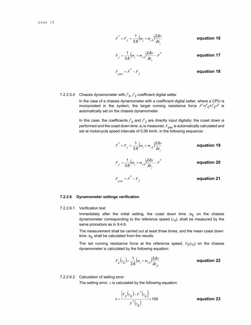
7.2.2.5.4 Chassis dynamometer with f*0, f*2 coefficient digital setter In the case of a chassis dynamometer with a coefficient digital setter, where a CPU is incorporated in the system, the target running resistance force F*=f*0+f*2v2 is automatically set on the chassis dynamometer.
In this case, the coefficients f*0 and f*2 are directly input digitally; the coast down is performed and the coast down time ∆ti is measured. Fpau is automatically calculated and set at motorcycle speed intervals of 0,06 km/h, in the following sequence:
( )i
rif*
tvmm
,FF
∆∆2
631
1+=+ equation 19
( ) *
irif F
tvmm
,F −+=
∆∆2
631
1 equation 20
f*
pau FFF −= equation 21
7.2.2.6 Dynamometer settings verification
7.2.2.6.1 Verification test Immediately after the initial setting, the coast down time ∆tE on the chassis dynamometer corresponding to the reference speed (v0), shall be measured by the same procedure as in 9.4.6.
The measurement shall be carried out at least three times, and the mean coast down time ∆tE shall be calculated from the results.
The set running resistance force at the reference speed, FE(v0) on the chassis dynamometer is calculated by the following equation:
( ) ( )E
riE tvmm
,vF
∆∆2
631
10 += equation 22
7.2.2.6.2 Calculation of setting error The setting error, ε is calculated by the following equation:
( ) ( )
( ) 1000
00×
−=
vF
vFvF
*
*E
ε equation 23
TRANS/WP.29/xxx
page 19
The chassis dynamometer shall be readjusted if the setting error does not satisfy the following criteria:
ε ≤2% for v0≥50 km/h
ε ≤3% for 30 km/h≤v0<50 km/h
ε ≤10% for v0<30 km/h
The procedure in 7.2.2.6.1 to 7.2.2.6.2 shall be repeated until the setting error satisfies the criteria.
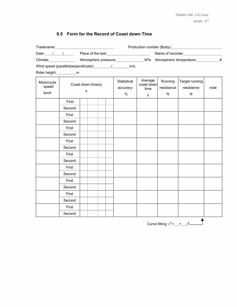
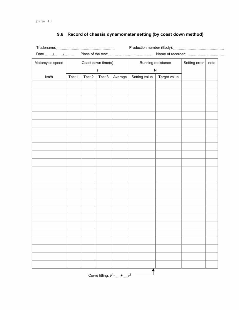
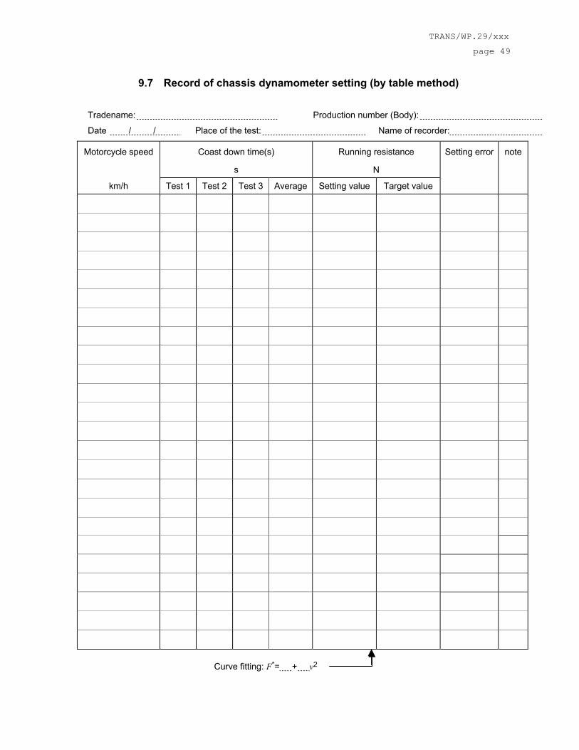
The chassis dynamometer setting and the observed errors shall be recorded. The examples of the record forms are given in annex 9.6 or annex 9.7.
7.2.3 Calibration of Analysers The quantity of gas at the indicated pressure compatible with the correct functioning of the equipment shall be injected into the analyser with the aid of the flow metre and the pressure-reducing valve mounted on each gas cylinder. The apparatus shall be adjusted to indicate as a stabilized value the value inserted on the standard gas cylinder. Starting from the setting obtained with the gas cylinder of greatest capacity, a curve shall be drawn of the deviations of the apparatus according to the content of the various standard cylinders used. The flame ionisation analyser shall be recalibrated periodically, at intervals of not more than one month, using air/propane or air/hexane mixtures with nominal hydrocarbon concentrations equal to 50 per cent and 90 per cent of full scale.
Non-dispersive infrared absorption analysers shall be checked at the same intervals using nitrogen/C0 and nitrogen/CO2 mixtures in nominal concentrations equal to 10, 40, 60, 85 and 90 per cent of full scale.
To calibrate the NOX chemiluminescence analyser, nitrogen/nitrogen oxide (NO) mixtures with nominal concentrations equal to 50 per cent and 90 per cent of full scale shall be used. The calibration of all three types of analysers shall be checked before each series of tests, using mixtures of the gases, which are measured in a concentration equal to 80 per cent of full scale. A dilution device can be applied for diluting a 100 per cent calibration gas to required concentration.
7.2.4 Vehicle Preconditioning The vehicle shall be moved to the test area and the following operations performed:
o The fuel tank(s) shall be drained through the provided fuel tank(s) drain(s) and charged with the test fuel as specified in 6.3 to half the tank(s) capacity.
o The vehicle shall be placed, either by being driven or pushed, on a dynamometer and operated through the cycles as specified in 6.4.4. The vehicle need not be cold, and may be used to set dynamometer power.
Practice runs over the prescribed driving schedule may be performed at test points, provided an emission sample is not taken, for the purpose of finding the minimum throttle action to maintain the proper speed-time relationship, or to permit sampling system adjustments.
Within five (5) minutes of completion of preconditioning, the vehicle shall be removed from the dynamometer and may be driven or pushed to the soak area to be parked. The vehicle shall be stored for not less than 12 hours prior to the cold start exhaust test or until oil Tª, cooling Tª or spark plug Tª equals the air temperature of the soak area.
page 20
7.2.5 Emissions Tests 7.2.5.1 Engine Starting and Restarting
The engine shall be started according to the manufacturer's recommended starting procedures. The test cycle run shall begin when the engine starts.
Vehicles equipped with automatic chokes shall be operated according to the instructions in the manufacturer's operating instructions or owner's manual including choke setting and "kick-down'' from cold fast idle. The transmission shall be placed in gear 15 seconds after the engine is started. If necessary, braking may be employed to keep the drive wheels from turning.
Vehicles equipped with manual chokes shall be operated according to the manufacturer's operating instructions or owner's manual. Where times are provided in the instructions, the point for operation may be specified, within 15 seconds of the recommended time.
The operator may use the choke, throttle etc. where necessary to keep the engine running.
If the manufacturer's operating instructions or owner's manual do not specify a warm engine starting procedure, the engine (automatic and manual choke engines) shall be started by opening the throttle about half way and cranking the engine until it starts.
If, during the cold start, the vehicle does not start after 10 seconds of cranking, or ten cycles of the manual starting mechanism, cranking shall cease and the reason for failure to start determined. The revolution counter on the constant volume sampler shall be turned off and the sample solenoid valves placed in the "standby'' position during this diagnostic period. In addition, either the CVS blower shall be turned off or the exhaust tube disconnected from the tailpipe during the diagnostic period.
If failure to start is an operational error, the vehicle shall be rescheduled for testing from a cold start. If failure to start is caused by vehicle malfunction, corrective action (following the unscheduled maintenance provisions) of less than 30 minutes duration may be taken and the test continued. The sampling system shall be reactivated at the same time cranking is started. When the engine starts, the driving schedule timing sequence shall begin. If failure to start is caused by vehicle malfunction and the vehicle cannot be started, the test shall be voided, the vehicle removed from the dynamometer, corrective action taken (following the unscheduled maintenance provisions), and the vehicle rescheduled for test. The reason for the malfunction (if determined) and the corrective action taken shall be reported.
If the vehicle does not start during the hot start after ten seconds of cranking, or ten cycles of the manual starting mechanism, cranking shall cease, the test shall be voided, the vehicle removed from the dynamometer, corrective action taken in accordance with Subpart E, Sec. 86.428 or 86.429, and the vehicle rescheduled for test. The reason for the malfunction (if determined) and the corrective action taken shall be reported.
If the engine "false starts'', the operator shall repeat the recommended starting procedure (such as resetting the choke, etc.)
7.2.5.2 Stalling If the engine stalls during an idle period, the engine shall be restarted immediately and the test continued. If the engine cannot be started soon enough to allow the vehicle to follow the next acceleration as prescribed, the driving schedule indicator shall be stopped. When the vehicle restarts, the driving schedule indicator shall be reactivated.
If the engine stalls during some operating mode other than idle, the driving schedule indicator shall be stopped, the vehicle shall then be restarted and accelerated to the speed required at that point in the driving schedule and the test continued. During acceleration to this point, shifting shall be performed in accordance with paragraph 6.4.5.
TRANS/WP.29/xxx
page 21
If the vehicle will not restart within one minute, the test shall be voided, the vehicle removed from the dynamometer, corrective action taken, and the vehicle rescheduled for test. The reason for the malfunction (if determined) and the corrective action taken shall be reported.
7.2.6 Drive Instructions The vehicle shall be driven with minimum throttle movement to maintain the desired speed. No simultaneous use of brake and throttle shall be permitted.
If the vehicle cannot accelerate at the specified rate, the vehicle shall be operated with the throttle fully opened until the vehicle speed reaches the value prescribed for that time in the driving schedule.
7.2.7 Dynamometer Test Runs The complete dynamometer test consists of consecutive parts as described in 6.4.4.
The following steps shall be taken for each test:
1. Place drive wheel of vehicle on dynamometer without starting engine.
2. Activate vehicle cooling fan.
3. For all vehicles, with the sample selector valves in the "standby'' position connect evacuated sample collection bags to the dilute exhaust and dilution air sample collection systems.
4. The measurement system for the fuel consumed, for the distance covered and for the time shall be engaged simultaneously. If necessary, a valve system shall be used for rapid changeover from the normal fuel supply line to the measuring system. The changeover shall not take longer than 0,2 s.
5. Start the CVS (if not already on), the sample pumps and the temperature recorder. (The heat exchanger of the constant volume sampler, if used, and sample lines should be preheated to their respective operating temperatures before the test begins.)
6. Adjust the sample flow rates to the desired flow rate and set the gas flow measuring devices to zero.
o For gaseous bag samples (except hydrocarbon samples), the minimum flow rate is 0.08 l/s.
o For hydrocarbon samples, the minimum FID (or HFID in the case of methanol-fuelled vehicles) flow rate is 0.031 l/s.
6. Attach the flexible exhaust tube to the vehicle tailpipe(s).
7. Start the gas flow measuring device, position the sample selector valves to direct the sample flow into the "transient'' exhaust sample bag, the "transient'' dilution air sample bag, turn the key on, and start cranking the engine.
8. Fifteen seconds after the engine starts, place the transmission in gear.
9. Twenty seconds after the engine starts, begin the initial vehicle acceleration of the driving schedule.
10. Operate the vehicle according to the driving cycles specified in 6.4.4.
11. At the end of the part 1 (or part 1, reduced speed in case of class 1, special vehicles) in “cold” condition, simultaneously switch the sample flows from the 1. bags and samples to the 2. bags and samples, switch off gas flow measuring device No. 1 and start gas flow measuring device No. 2.
12. In case of class 3 vehicles, at the end of part 2 (or part 1 in case of class 1 vehicles or part 1, reduced speed in case of class 1, special vehicles), simultaneously switch
page 22
the sample flows from the 2. bags and samples to the 3. bags and samples, switch off gas flow measuring device No. 2 and, start gas flow measuring device No. 3.
13. Before starting a new part, record the measured roll or shaft revolutions and reset the counter or switch to a second counter. As soon as possible, transfer the exhaust and dilution air samples to the analytical system and process the samples according to paragraph 8.1.2, obtaining a stabilised reading of the exhaust bag sample on all analysers within 20 minutes of the end of the sample collection phase of the test.
14. Turn the engine off 2 seconds after the end of the last part of the test.
15. Immediately after the end of the sample period, turn off the cooling fan.
16. Turn off the CVS or CFV or disconnect the exhaust tube from the tailpipe(s) of the vehicle.
17. Disconnect the exhaust tube from the vehicle tailpipe(s) and remove the vehicle from dynamometer.
18. For comparison and analysis reasons besides the bag results also second by second data of the emissions (diluted gas) have to be monitored. For the same reasons also the temperatures of the cooling water and the crankcase oil as well as the catalyst temperature shall be recorded.
19. Each test shall be repeated at least twice.
7.2.8 Records required The following information shall be recorded with respect to each test:
1. Test number,
2. System or device tested (brief description),
3. Date and time of day for each part of the test schedule,
4. Instrument operator,
5. Driver or operator,
6. Vehicle: Make, Vehicle identification number, Model year, Transmission type, Odometer reading at initiation of preconditioning, Engine displacement, Engine family, Emission control system, Recommended idle RPM, Nominal fuel tank capacity, Inertial loading, Actual curb mass recorded at 0 kilometres, and Drive wheel tire pressure.
7. Dynamometer serial number: As an alternative to recording the dynamometer serial number, a reference to a vehicle test cell number may be used, with the advance approval of the Administrator, provided the test cell records show the pertinent instrument information.
8. All pertinent instrument information such as tuning-gain-serial number-detector number-range. As an alternative, a reference to a vehicle test cell number may be used, with the advance approval of the Administrator, provided test cell calibration records show the pertinent instrument information.
9. Recorder Charts: Identify zero, span, exhaust gas, and dilution air sample traces.
10. Test cell barometric pressure, ambient temperature and humidity.
Note: A central laboratory barometer may be used; Provided, that individual test cell barometric pressures are shown to be within ±0.1 percent of the barometric pressure at the central barometer location.
11. Pressure of the mixture of exhaust and dilution air entering the CVS metering device, the pressure increase across the device, and the temperature at the inlet. The temperature should be recorded continuously or digitally to determine temperature variations.
TRANS/WP.29/xxx
page 23
12. The number of revolutions of the positive displacement pump accumulated during each test phase while exhaust samples are being collected. The number of standard cubic meters metered by a critical flow venturi during each test phase would be the equivalent record for a CFV-CVS.
13. The humidity of the dilution air.
Note: If conditioning columns are not used this measurement can be deleted. If the conditioning columns are used and the dilution air is taken from the test cell, the ambient humidity can be used for this measurement.
14. The emissions results for each part of the test.
15. The driving distance for each part of the test, calculated from the measured roll or shaft revolutions.
16. The actual vehicle speed pattern of the test.
17. The second by second emission values.
7.3 Type II Tests
7.3.1 Conditions of Measurement The Type II test specified in paragraph 6.5 must be measured immediately after the Type I test with the engine at normal idling speed and at high idle.
The following parameters must be measured and recorded at normal idling speed and at high idle speed:
o the carbon monoxide content by volume of the exhaust gases emitted,
o the carbon dioxide content by volume of the exhaust gases emitted,
o the engine speed during the test, including any tolerances,
o the engine oil temperature at the time of the test.
7.3.2 Sampling of Exhaust Gases The exhaust outlets shall be provided with an air-tight extension, so that the sample probe used to collect exhaust gases may be inserted into the exhaust outlet at least 60 cm, without increasing the back pressure of more than 125 mm H20, and without disturbance of the vehicle running. The shape of this extension shall however be chosen in order to avoid, at the location of the sample probe, any appreciable dilution of exhaust gases in the air. Where a motorcycle is equipped with an exhaust system having multiple outlets, either these shall be joined to a common pipe or the content of carbon monoxide must be collected from each of them, the result of the measurement being reached from the arithmetical average of these contents.
The concentrations in CO (CCO) and CO2 (CCO2 ) shall be determined from the measuring instrument readings or recordings, by use of appropriate calibration curves. The results have to be corrected according to paragraph 8.2.
8 Analysis of Results 8.1 Type I Tests
8.1.1 Speed Tolerances The deviations of the roller speed from the set speed of the cycles must meet the requirements of paragraph 6.4.4.2. If not, the test results shall not be used for the further analysis and the run has to be repeated.
page 24
8.1.2 Exhaust Emission and Fuel Consumption Analysis 8.1.2.1 Analysis of the samples contained in the bags
The analysis shall begin as soon as possible, and in any event not later than 20 minutes after the end of the tests, in order to determine:
o The concentrations of hydrocarbons, carbon monoxide, nitrogen oxides and carbon dioxide in the sample of dilution air contained in bags B;
o The concentrations of hydrocarbons, carbon monoxide, nitrogen oxides and carbon dioxide in the sample of diluted exhaust gases contained in bags A.
8.1.2.2 Calibration of analysers and concentration results The analysis of the results has to be carried out in the following steps:
1. Prior to each sample analysis the analyser range to be used for each pollutant must be set to zero with the appropriate zero gas.
2. The analysers are then set to the calibration curves by means of span gases of nominal concentrations of 70 to 100% of the range.
3. The analysers' zeros are then rechecked. If the reading differs by more than 2% of range from that set in 2, the procedure is repeated.
4. The samples are then analysed.
5. After the analysis, zero and span points are rechecked using the same gases. If these rechecks are within 2% of those in 3, the analysis is considered acceptable.
6. At all points in this Section the flow-rates and pressures of the various gases must be the same as those used during calibration of the analysers.
7. The figure adopted for the concentration of each pollutant measured in the gases is that read off after stabilisation on the measuring device.
8.1.2.3 Measuring the distance covered The distance actually covered for a test part shall be arrived at by multiplying the number of revolutions read from the cumulative counter (see paragraph 7.2.7) by the circumference of the roller. This distance shall be measured in km.
8.1.2.4 Determination of the quantity of gas emitted The reported test results shall be computed for each test and each cycle part by use of the following formulas. The results of all emission tests shall be rounded, using the "Rounding-Off Method'' specified in [ASTM E 29-67], to the number of places to the right of the decimal point indicated by expressing the applicable standard to three significant figures.
8.1.2.4.1 Total volume of diluted gas The total volume of diluted gas, expressed in m3/cycle part, adjusted to the reference conditions of O°C (273°K) and 101,3 kPa is calculated by
V = V0 * N * (Pa – Pi) * 273,2 / 101,3 / (Tp + 273,2) equation 24 where
V0 is the volume of gas displaced by pump P during one revolution, expressed in m3/revolution. This volume is a function of the differences between the intake and output sections of the pump,
N is the number of revolutions made by pump P during each part of the test;
Pa is the ambient pressure in kPa;
Pi is the average under-pressure during the test part in the intake section of pump P, expressed in kPa;
Tp is the temperature of the diluted gases during the test part in °C, measured in the
TRANS/WP.29/xxx
page 25
intake section of pump P.
8.1.2.4.2 Hydrocarbons The mass of unburned hydrocarbons emitted by the vehicle's exhaust during the test shall be calculated by means of the following formula:
HCm = HCc * V * dHC / dist / 106 equation 25 where
HCm is the mass of hydrocarbons emitted during the test part, in g/km
dist is the distance defined in paragraph 8.1.2.3 above;
dHC is the density of the hydrocarbons at a temperature of 0°C and a pressure of 101,3 kPa, where the average carbon/hydrogen ratio is 1:1.85; dHC = 0.619 kg/m3,
HCc is the concentration of diluted gases, expressed in parts per million of carbon equivalent (e.g. the concentration in propane multiplied by 3), corrected to take account of the dilution air by:
HCc = HCe - Hcd * (1 – 1/DF) equation 26 where
HCe is the concentration of hydrocarbons expressed in parts per million of carbon equivalent, in the sample of diluted gases collected in bag A,
HCd is the concentration of hydrocarbons expressed in parts per million of carbon equivalent, in the sample of dilution air collected in bag B,
DF is the coefficient defined in paragraph 8.1.2.4.6 below,
V is the total volume, see paragraph 8.1.2.4.1.
8.1.2.4.3 Carbon Monoxide The mass of carbon monoxide emitted by the vehicle's exhaust during the test shall be calculated by means of the following formula:
COm = COc * V * dCO / dist / 106 equation 27 where
COm is the mass of carbon monoxide emitted during the test part, in g/km
dist is the distance defined in paragraph 8.1.2.3 above;
dCO is the density of the carbon monoxide at a temperature of 0°C and a pressure of 101,3 kPa, dCO = 1.250 kg/m3,
COc is the concentration of diluted gases, expressed in parts per million of carbon monoxide, corrected to take account of the dilution air by:
COc = COe - COd * (1 – 1/DF) equation 28 where
COe is the concentration of carbon monoxide expressed in parts per million, in the sample of diluted gases collected in bag A,
COd is the concentration of carbon monoxide expressed in parts per million, in the sample of dilution air collected in bag B,
DF is the coefficient defined in paragraph 8.1.2.4.6 below,
V is the total volume, see paragraph 8.1.2.4.1.
page 26
8.1.2.4.4 Nitrogen Oxides The mass of nitrogen oxides emitted by the vehicle's exhaust during the test shall be calculated by means of the following formula:
NOxm = NOxc * Kh * V * dNO2 / dist / 106 equation 29 where
NOxm is the mass of nitrogen oxides emitted during the test part, in g/km
dist is the distance defined in paragraph 8.1.2.3 above;
dNO2 is the density of the nitrogen oxides in the exhaust gases, assuming that they will be in the form of nitric oxide, at a temperature of 0°C and a pressure of 101,3 kPa, dNO2 = 0.619 kg/m3,
NOxc is the concentration of diluted gases, expressed in parts per million, corrected to take account of the dilution air by:
NOxc = NOxe - NOxd * (1 – 1/DF) equation 30 where
NOxe is the concentration of nitrogen oxides expressed in parts per million of nitrogen oxides, in the sample of diluted gases collected in bag A,
NOxd is the concentration of nitrogen oxides expressed in parts per million of nitrogen oxides, in the sample of dilution air collected in bag B,
DF is the coefficient defined in paragraph 8.1.2.4.6 below,
H is the absolute humidity in g of water per kg of dry air,
H in g/kg = 6,211 * U * Pd / (Pa – Pd * U / 100) equation 32 where
U is the percentage humidity,
Pd is the saturated pressure of water at the test temperature, in kPa,
Pa is atmospheric pressure in kPa.
8.1.2.4.5 Carbon Dioxide The mass of carbon dioxide emitted by the vehicle's exhaust during the test shall be calculated by means of the following formula:
CO2m = CO2c * V * dCO2 / dist / 102 equation 33 where
CO2m is the mass of carbon dioxide emitted during the test part, in g/km
dist is the distance defined in paragraph 8.1.2.3 above;
dCO2 is the density of the carbon dioxide at a temperature of 0°C and a pressure of 101,3 kPa, dCO2 = 1830 g/m3,
TRANS/WP.29/xxx
page 27
CO2c is the concentration of diluted gases, expressed in percent carbon dioxide equivalent, corrected to take account of the dilution air by:
CO2c = CO2e - CO2d * (1 – 1/DF) equation 34 where
CO2e is the concentration of carbon dioxide expressed in percent, in the sample of diluted gases collected in bag A,
CO2d is the concentration of carbon dioxide expressed in percent, in the sample of dilution air collected in bag B,
DF is the coefficient defined in paragraph 8.1.2.4.6 below,
V is the total volume, see paragraph 8.1.2.4.1.
8.1.2.4.6 DF DF (dilution factor) is a coefficient expressed by the formula
DF = 31,4 / (CO2 + (CO + HC)*10-4) in vol-% equation 35 “CO, CO2 and HC" are the concentrations of carbon monoxide and hydrocarbons, expressed in ppm and carbon dioxide, expressed in per cent, in the sample of diluted gases contained in bag A.
8.1.2.5 Fuel Consumption Calculation The fuel consumption, expressed in litres per 100 km is calculated by means of the following formulae:
8.1.2.5.1 Vehicles with a positive ignition engine fuelled with petrol
FC = (0.1154 / D) * (0.866 * HC + 0.429 * CO + 0.273 * CO2) equation 36 where
FC is the fuel consumption in l/100 km
HC is the measured emission of hydrocarbons in g/km
CO is the measured emission of carbon monoxide in g/km
CO2 is the measured emission of carbon dioxide in g/km
D is the density of the test fuel.
In the case of gaseous fuels this is the density at 15°C.
8.1.2.5.2 Vehicles with a compression ignition engine
FC = (0.1155 / D) * (0.866 * HC + 0.429 * CO + 0.273 * CO2) equation 37 where
FC is the fuel consumption in l/100 km
HC is the measured emission of hydrocarbons in g/km
CO is the measured emission of carbon monoxide in g/km
CO2 is the measured emission of carbon dioxide in g/km
page 28
D is the density of the test fuel.
In the case of gaseous fuels this is the density at 15°C.
8.1.2.6 Weighting of Results The emission results in g/km and the fuel consumption in l/100 km obtained by the calculation method described in paragraph 8.1.2 of the three tests are averaged for each cycle part. The final result shall be calculated by means of the following formulae, depending on the vehicle class as defined in paragraph 6.2:
Class 1 R = R1cold * w1cold + R1hot * w1hot equation 38
Class 2 R = R1cold * w1 + R2 * w2
Class 3 R = R1cold * w1 + R2 * w2 + R3 * w3
for each pollutant, the carbon dioxide emission and the fuel consumption using the weightings shown in Table 6.
vehicle class cycle weightingpart 1, cold 50%part 1, hot 50%part 1, cold 30%
part 2 70%part 1, cold 25%
part 2 50%part 3 25%
class 1
class 2
class 3
Table 6: Weighting factors for the final emission and fuel consumption results
8.2 Type II Tests The corrected concentration for carbon monoxide regarding two-stroke engines is:
CCOcorr = CCO * 10 / (CCO + CCO2) in vol-% equation 39 The corrected concentration for carbon monoxide regarding four-stroke engines is:
The concentration in CCO measured according to paragraph 7.3.2 need not be corrected if the total of the concentrations measured (CCO + CCO2) is at least 10 for two-stroke engines and 15 for four-stroke engines.
TRANS/WP.29/xxx
page 29
9 Annexes 9.1 ESSENTIAL CHARACTERISTICS OF THE ENGINE, the reduction
systems AND INFORMATION CONCERNING THE CONDUCT OF TESTS
1. Description of Engine 1
1.1. Manufacturer:
1.1.1. Manufacturer's engine code (as marked on the engine or other means of identification):
1.2. Internal combustion engine:
1.2.1. Specific engine information:
1.2.1.1. Working principle: positive-ignition / compression-ignition, four stroke / two stroke 1
1.2.1.2. Number, arrangement and firing order of cylinders:
1.2.1.2.1. Bore 2: mm
1.2.1.2.2. Stroke 2: mm
1.2.1.3. Engine capacity 3: cm3
1.2.1.4. Volumetric compression ratio 4 :
1.2.1.5. Drawing(s) of combustion chamber and piston crown:
1.2.1.6. Idle speed 4:
1.2.1.7. Carbon monoxide content by volume in the exhaust gas with the engine idling: ....... per cent (according to the manufacturer’s specifications) 4
1.2.1.8. Maximum net power: .......... kW at: .......... min-1
1.2.2. Fuel: leaded petrol / unleaded petrol / diesel 1
1.2.8.1. Description and drawings of the exhaust system:
1.2.9. Valve timing or equivalent data.
1.2.9.1. Maximum lift of valves, angles of operating and closing or timing details of alternative distribution systems, in relation to dead centres:
1.2.9.2. Reference and/or setting ranges 1:
1.2.10. Lubricant used.
1.2.10.1. Make:
1.2.10.2. Type:
1.2.11. Measures taken against air pollution.
1.2.11.1. Device for recycling crankcase gases (description and/or drawings):
1.2.11.2. Additional pollution control devices (if any, and if not covered by another heading):
1.2.11.2.1. Catalytic converter: yes / no 1
1.2.11.2.1.1. Number of catalytic converters and elements:
1.2.11.2.1.2. Dimensions and shape of the catalytic converter(s) (volume, ...):
1.2.11.2.1.3. Type of catalytic action:
1.2.11.2.1.4. Total charge of precious metal:
1.2.11.2.1.5. Relative concentration:
1.2.11.2.1.6. Substrate (structure and material):
1.2.11.2.1.7. Cell density:
1.2.11.2.1.8. Type of casing for catalytic converter(s):
1.2.11.2.1.9. Positioning of the catalytic converter(s) (Place and reference distances in the exhaust system):
1.2.11.2.1.10. Oxygen sensor: type:
1.2.11.2.1.10.1. Location of oxygen sensor:
1.2.11.2.1.10.2. Control range of oxygen sensor:
1.2.11.2.2. Air injection: yes / no 1
1.2.11.2.2.1. Type (pulse air, air pump, ...):
1.2.11.2.3. EGR: yes / no 1
1.2.11.2.3.1. Characteristics (flow, ...):
1.2.11.2.4. Evaporative emission control system.
Complete detailed description of the devices and their state of tune:
Drawing of the evaporative control system:
TRANS/WP.29/xxx
page 33
Drawing of the carbon canister:
Drawing of the fuel tank with indication of capacity and material:
1.2.11.2.5. Particulate trap: yes / no 1
1.2.11.2.5.1. Dimensions and shape of the particulate trap (capacity):
1.2.11.2.5.2. Type of particulate trap and design:
1.2.11.2.5.3. Location of the particulate trap (reference distances in the exhaust system):
1.2.11.2.5.4. Regeneration system/method. Description and drawing:
1.2.11.2.6. Other systems (description and working principles):
page 34
9.2 Driving Cycles for Type I Tests
0
10
20
30
40
50
60
70
0 60 120 180 240 300 360 420 480 540 600time in s
vehi
cle
spee
d in
km
/h
part 1, version 9, reduced speedpart 1, version 9
Figure 3: Cycle part 1
TRANS/WP.29/xxx
page 35
0
10
20
30
40
50
60
70
80
90
100
0 60 120 180 240 300 360 420 480 540 600time in s
vehi
cle
spee
d in
km
/h
part 2, version 9, reduced speedpart 2, version 9
Figure 4: Cycle part 2 for vehicle classes 2 and 3
0
10
20
30
40
50
60
70
80
90
100
110
120
130
0 60 120 180 240 300 360 420 480 540 600time in s
vehi
cle
spee
d in
km
/h
part 3, version 9, reduced speed
part 3, version 9
Figure 5: Cycle part 3 for vehicle class 3
page 36
time nor-mal
redu-ced
speedstop acc crui-
se decelno
gear-shift
no 1. gear time nor-
mal
redu-ced
speedstop acc crui-
se decelno
gear-shift
no 1. gear
1 0.0 0.0 x 61 29.7 29.7 x2 0.0 0.0 x 62 26.9 26.9 x3 0.0 0.0 x 63 23.0 23.0 x4 0.0 0.0 x 64 18.7 18.7 x5 0.0 0.0 x 65 14.2 14.2 x6 0.0 0.0 x 66 9.4 9.4 x7 0.0 0.0 x 67 4.9 4.9 x8 0.0 0.0 x 68 2.0 2.0 x9 0.0 0.0 x 69 0.0 0.0 x
10 0.0 0.0 x 70 0.0 0.0 x11 0.0 0.0 x 71 0.0 0.0 x12 0.0 0.0 x 72 0.0 0.0 x13 0.0 0.0 x 73 0.0 0.0 x14 0.0 0.0 x 74 1.7 1.7 x15 0.0 0.0 x 75 5.8 5.8 x16 0.0 0.0 x 76 11.8 11.8 x17 0.0 0.0 x 77 18.3 18.3 x18 0.0 0.0 x 78 24.5 24.5 x19 0.0 0.0 x 79 29.4 29.4 x20 0.0 0.0 x 80 32.5 32.5 x21 0.0 0.0 x 81 34.2 34.2 x22 1.0 1.0 x 82 34.4 34.4 x23 2.6 2.6 x 83 34.5 34.5 x24 4.8 4.8 x 84 34.6 34.6 x25 7.2 7.2 x 85 34.7 34.7 x26 9.6 9.6 x 86 34.8 34.8 x27 12.0 12.0 x 87 35.2 35.2 x28 14.3 14.3 x 88 36.0 36.0 x29 16.6 16.6 x 89 37.0 37.0 x30 18.9 18.9 x 90 37.9 37.9 x31 21.2 21.2 x 91 38.5 38.5 x32 23.5 23.5 x 92 38.8 38.8 x33 25.6 25.6 x 93 38.8 38.8 x34 27.1 27.1 x 94 38.7 38.7 x35 28.0 28.0 x 95 38.4 38.4 x36 28.7 28.7 x 96 38.0 38.0 x37 29.2 29.2 x 97 37.4 37.4 x38 29.8 29.8 x 98 36.9 36.9 x39 30.3 30.3 x x 99 36.6 36.6 x40 29.6 29.6 x x 100 36.4 36.4 x41 28.7 28.7 x x 101 36.4 36.4 x42 27.9 27.9 x x x 102 36.5 36.5 x43 27.5 27.5 x x x 103 36.7 36.7 x44 27.3 27.3 x x x 104 36.9 36.9 x45 27.3 27.3 x x x 105 37.0 37.0 x46 27.4 27.4 x x x 106 37.2 37.2 x47 27.5 27.5 x x x 107 37.3 37.3 x48 27.6 27.6 x x x 108 37.4 37.4 x49 27.6 27.6 x x x 109 37.3 37.3 x50 27.7 27.7 x x x 110 36.8 36.8 x51 27.8 27.8 x x 111 35.8 35.8 x52 28.1 28.1 x x 112 34.6 34.6 x53 28.6 28.6 x x 113 31.8 31.8 x54 28.9 28.9 x x 114 28.9 28.9 x55 29.2 29.2 x x 115 26.7 26.7 x x56 29.4 29.4 x x 116 24.6 24.6 x x57 29.7 29.7 x x 117 25.2 25.2 x x58 30.1 30.1 x x 118 26.2 26.2 x x59 30.5 30.5 x x 119 27.5 27.5 x x60 30.7 30.7 x x 120 29.2 29.2 x x
v in km/h v in km/h
Table 7: Cycle part 1, 1 to 120 s
TRANS/WP.29/xxx
page 37
time nor-mal
redu-ced
speedstop acc crui-
se decelno
gear-shift
no 1. gear time nor-
mal
redu-ced
speedstop acc crui-
se decelno
gear-shift
no 1. gear
121 31.0 31.0 x x 181 0.0 0.0 x122 32.8 32.8 x x 182 0.0 0.0 x123 34.3 34.3 x x 183 2.0 2.0 x124 35.1 35.1 x 184 6.0 6.0 x125 35.3 35.3 x 185 12.4 12.4 x126 35.1 35.1 x 186 21.4 21.4 x127 34.6 34.6 x 187 30.0 30.0 x128 33.7 33.7 x 188 37.1 37.1 x129 32.2 32.2 x 189 42.5 40.5 x130 29.6 29.6 x 190 46.6 42.6 x131 26.0 26.0 x 191 49.8 43.8 x132 22.0 22.0 x 192 52.4 44.4 x133 18.5 18.5 x 193 54.4 45.4 x134 16.6 16.6 x 194 55.6 45.6 x135 17.5 17.5 x 195 56.1 46.1 x136 20.9 20.9 x 196 56.2 46.2 x137 25.2 25.2 x 197 56.2 46.2 x138 29.1 29.1 x 198 56.2 46.2 x139 31.4 31.4 x 199 56.7 46.7 x140 31.9 31.9 x 200 57.2 47.2 x141 31.4 31.4 x 201 57.7 47.7 x142 30.6 30.6 x 202 58.2 48.2 x143 29.5 29.5 x 203 58.7 48.7 x144 27.9 27.9 x 204 59.3 49.3 x145 24.9 24.9 x 205 59.8 49.8 x146 20.2 20.2 x 206 60.0 50.0 x147 14.8 14.8 x 207 60.0 50.0 x148 9.5 9.5 x 208 59.9 49.9 x149 4.8 4.8 x 209 59.9 49.9 x150 1.4 1.4 x 210 59.9 49.9 x151 0.0 0.0 x 211 59.9 49.9 x152 0.0 0.0 x 212 59.9 49.9 x153 0.0 0.0 x 213 59.8 49.8 x154 0.0 0.0 x 214 59.6 49.6 x155 0.0 0.0 x 215 59.1 49.1 x156 0.0 0.0 x 216 57.1 47.1 x157 0.0 0.0 x 217 53.2 43.2 x158 0.0 0.0 x 218 48.3 38.3 x159 0.0 0.0 x 219 43.9 33.9 x160 0.0 0.0 x 220 40.3 30.3 x161 0.0 0.0 x 221 39.5 29.5 x162 0.0 0.0 x 222 41.3 31.3 x163 0.0 0.0 x 223 45.2 35.2 x164 0.0 0.0 x 224 50.1 40.1 x165 0.0 0.0 x 225 53.7 43.7 x166 0.0 0.0 x 226 55.8 45.8 x167 0.0 0.0 x 227 55.8 45.8 x168 0.0 0.0 x 228 54.7 44.7 x169 0.0 0.0 x 229 53.3 43.3 x170 0.0 0.0 x 230 52.2 42.2 x171 0.0 0.0 x 231 52.0 42.0 x172 0.0 0.0 x 232 52.1 42.1 x173 0.0 0.0 x 233 51.8 41.8 x174 0.0 0.0 x 234 50.8 41.8 x175 0.0 0.0 x 235 49.2 41.2 x176 0.0 0.0 x 236 47.4 40.4 x177 0.0 0.0 x 237 45.7 39.7 x178 0.0 0.0 x 238 43.9 38.9 x179 0.0 0.0 x 239 42.0 38.7 x180 0.0 0.0 x 240 40.2 38.7 x
v in km/h v in km/h
Table 8: Cycle part 1, 121 to 240 s
page 38
time nor-mal
redu-ced
speedstop acc crui-
se decelno
gear-shift
no 1. gear time nor-
mal
redu-ced
speedstop acc crui-
se decelno
gear-shift
no 1. gear
241 38.3 38.3 x 301 30.6 30.6 x x242 36.4 36.4 x 302 28.9 28.9 x243 34.6 34.6 x 303 27.8 27.8 x244 32.7 32.7 x 304 27.2 27.2 x245 30.6 30.6 x 305 26.9 26.9 x246 28.1 28.1 x 306 26.5 26.5 x247 25.4 25.4 x 307 26.1 26.1 x248 23.1 23.1 x 308 25.7 25.7 x249 21.2 21.2 x 309 25.5 25.5 x250 19.5 19.5 x 310 25.7 25.7 x251 17.8 17.8 x 311 26.4 26.4 x252 15.2 15.2 x 312 27.3 27.3 x253 11.5 11.5 x 313 28.1 28.1 x254 7.2 7.2 x 314 27.9 27.9 x255 2.5 2.5 x 315 26.0 26.0 x256 0.0 0.0 x 316 22.7 22.7 x257 0.0 0.0 x 317 19.0 19.0 x258 0.0 0.0 x 318 16.0 16.0 x259 0.0 0.0 x 319 14.6 14.6 x260 0.0 0.0 x 320 15.2 15.2 x261 0.0 0.0 x 321 16.9 16.9 x262 0.0 0.0 x 322 19.3 19.3 x263 0.0 0.0 x 323 22.0 22.0 x264 0.0 0.0 x 324 24.6 24.6 x265 0.0 0.0 x 325 26.8 26.8 x266 0.0 0.0 x 326 27.9 27.9 x267 0.5 0.5 x 327 28.1 28.1 x268 2.9 2.9 x 328 27.7 27.7 x269 8.2 8.2 x 329 27.2 27.2 x270 13.2 13.2 x 330 26.7 26.7 x271 17.8 17.8 x 331 26.6 26.6 x272 21.4 21.4 x 332 26.8 26.8 x273 24.1 24.1 x 333 27.0 27.0 x274 26.4 26.4 x 334 27.2 27.2 x275 28.4 28.4 x 335 27.4 27.4 x276 29.9 29.9 x 336 27.5 27.5 x277 30.4 30.4 x 337 27.7 27.7 x278 30.5 30.5 x 338 27.9 27.9 x279 30.3 30.3 x 339 28.1 28.1 x280 30.2 30.2 x 340 28.3 28.3 x281 30.1 30.1 x 341 28.6 28.6 x282 30.1 30.1 x 342 29.0 29.0 x283 30.1 30.1 x 343 29.5 29.5 x284 30.1 30.1 x 344 30.1 30.1 x285 30.1 30.1 x 345 30.5 30.5 x286 30.1 30.1 x 346 30.7 30.7 x287 30.2 30.2 x 347 30.8 30.8 x288 30.4 30.4 x x 348 30.8 30.8 x289 31.0 31.0 x x 349 30.8 30.8 x290 31.8 31.8 x x 350 30.8 30.8 x291 32.7 32.7 x x 351 30.8 30.8 x292 33.6 33.6 x x 352 30.8 30.8 x293 34.4 34.4 x x 353 30.8 30.8 x294 35.0 35.0 x x 354 30.9 30.9 x295 35.4 35.4 x x 355 30.9 30.9 x x x296 35.5 35.5 x x 356 30.9 30.9 x x x297 35.3 35.3 x x 357 30.8 30.8 x x x298 34.9 34.9 x x 358 30.4 30.4 x x x299 33.9 33.9 x x 359 29.6 29.6 x x300 32.4 32.4 x x 360 28.4 28.4 x x
v in km/h v in km/h
Table 9: Cycle part 1, 241 to 360 s
TRANS/WP.29/xxx
page 39
time nor-mal
redu-ced
speedstop acc crui-
se decelno
gear-shift
no 1. gear time nor-
mal
redu-ced
speedstop acc crui-
se decelno
gear-shift
no 1. gear
361 27.1 27.1 x x 421 34.0 34.0 x362 26.0 26.0 x x 422 35.4 35.4 x363 25.4 25.4 x x 423 36.5 36.5 x364 25.5 25.5 x x x 424 37.5 37.5 x365 26.3 26.3 x x x 425 38.6 38.6 x366 27.3 27.3 x x x 426 39.7 39.7 x367 28.4 28.4 x x x 427 40.7 40.7 x368 29.2 29.2 x x x 428 41.5 41.5 x369 29.5 29.5 x x x 429 41.7 41.7 x370 29.4 29.4 x x x 430 41.5 41.5 x371 28.9 28.9 x x x 431 41.0 41.0 x372 28.1 28.1 x x x 432 40.6 40.6 x373 27.2 27.2 x x x 433 40.3 40.3 x374 26.3 26.3 x x x 434 40.1 40.1 x375 25.7 25.7 x x x 435 40.1 40.1 x376 25.5 25.5 x x x 436 39.8 39.8 x377 25.6 25.6 x x x 437 38.9 38.9 x378 26.0 26.0 x x x 438 37.5 37.5 x379 26.4 26.4 x x x 439 35.8 35.8 x380 27.0 27.0 x x x 440 34.2 34.2 x381 27.7 27.7 x x x 441 32.5 32.5 x382 28.5 28.5 x x x 442 30.9 30.9 x383 29.4 29.4 x x x 443 29.4 29.4 x384 30.2 30.2 x x x 444 28.0 28.0 x385 30.5 30.5 x x x 445 26.5 26.5 x386 30.3 30.3 x x 446 25.0 25.0 x387 29.5 29.5 x x 447 23.4 23.4 x388 28.7 28.7 x x 448 21.9 21.9 x389 27.9 27.9 x x 449 20.4 20.4 x390 27.5 27.5 x 450 19.4 19.4 x391 27.3 27.3 x 451 18.8 18.8 x392 27.0 27.0 x 452 18.4 18.4 x393 26.5 26.5 x 453 18.0 18.0 x394 25.8 25.8 x 454 17.5 17.5 x395 25.0 25.0 x 455 16.9 16.9 x396 21.5 21.5 x 456 16.4 16.4 x397 16.0 16.0 x 457 16.6 16.6 x398 10.0 10.0 x 458 17.7 17.7 x399 5.0 5.0 x 459 19.3 19.3 x400 2.2 2.2 x 460 20.9 20.9 x401 1.0 1.0 x 461 22.3 22.3 x402 0.0 0.0 x 462 23.2 23.2 x403 0.0 0.0 x 463 23.2 23.2 x404 0.0 0.0 x 464 22.2 22.2 x405 0.0 0.0 x 465 20.3 20.3 x406 0.0 0.0 x 466 17.9 17.9 x407 0.0 0.0 x 467 15.2 15.2 x408 1.2 1.2 x 468 12.3 12.3 x409 3.2 3.2 x 469 9.3 9.3 x410 5.9 5.9 x 470 6.4 6.4 x411 8.8 8.8 x 471 3.8 3.8 x412 12.0 12.0 x 472 1.9 1.9 x413 15.4 15.4 x 473 0.9 0.9 x414 18.9 18.9 x 474 0.0 0.0 x415 22.1 22.1 x 475 0.0 0.0 x416 24.7 24.7 x 476 0.0 0.0 x417 26.8 26.8 x 477 0.0 0.0 x418 28.7 28.7 x 478 0.0 0.0 x419 30.6 30.6 x 479 0.0 0.0 x420 32.4 32.4 x 480 0.0 0.0 x
v in km/h v in km/h
Table 10: Cycle part 1, 361 to 480 s
page 40
time nor-mal
redu-ced
speedstop acc crui-
se decelno
gear-shift
no 1. gear time nor-
mal
redu-ced
speedstop acc crui-
se decelno
gear-shift
no 1. gear
481 0.0 0.0 x 541 0.0 0.0 x482 0.0 0.0 x 542 2.7 2.7 x483 0.0 0.0 x 543 8.0 8.0 x484 0.0 0.0 x 544 16.0 16.0 x485 0.0 0.0 x 545 24.0 24.0 x486 1.4 1.4 x 546 32.0 32.0 x487 4.5 4.5 x 547 37.2 37.2 x488 8.8 8.8 x 548 40.4 40.4 x489 13.4 13.4 x 549 43.0 43.0 x490 17.3 17.3 x 550 44.6 44.6 x491 19.2 19.2 x 551 45.2 45.2 x492 19.7 19.7 x 552 45.3 45.3 x493 19.8 19.8 x 553 45.4 45.4 x494 20.7 20.7 x 554 45.5 45.5 x495 23.6 23.6 x 555 45.6 45.6 x496 28.1 28.1 x 556 45.7 45.7 x497 32.8 32.8 x 557 45.8 45.8 x498 36.3 36.3 x 558 45.9 45.9 x499 37.1 37.1 x 559 46.0 46.0 x500 35.1 35.1 x x 560 46.1 46.1 x501 31.1 31.1 x x 561 46.2 46.2 x502 28.0 28.0 x x 562 46.3 46.3 x503 27.5 27.5 x x 563 46.4 46.4 x504 29.5 29.5 x x 564 46.7 46.7 x505 34.0 34.0 x x 565 47.2 47.2 x506 37.0 37.0 x x 566 48.0 48.0 x507 38.0 38.0 x x 567 48.9 48.9 x508 36.1 36.1 x 568 49.8 49.8 x509 31.5 31.5 x 569 50.5 50.5 x510 24.5 24.5 x 570 51.0 51.0 x511 17.5 17.5 x 571 51.1 51.1 x512 10.5 10.5 x 572 51.0 51.0 x513 4.5 4.5 x 573 50.4 50.4 x514 1.0 1.0 x 574 49.0 49.0 x515 0.0 0.0 x 575 46.7 46.7 x516 0.0 0.0 x 576 44.0 44.0 x517 0.0 0.0 x 577 41.1 41.1 x518 0.0 0.0 x 578 38.3 38.3 x519 2.9 2.9 x 579 35.4 35.4 x520 8.0 8.0 x 580 31.8 31.8 x521 16.0 16.0 x 581 27.3 27.3 x522 24.0 24.0 x 582 22.4 22.4 x523 32.0 32.0 x 583 17.7 17.7 x524 38.8 38.8 x 584 13.4 13.4 x525 43.1 43.1 x 585 9.3 9.3 x526 46.0 46.0 x 586 5.5 5.5 x527 47.5 47.5 x 587 2.0 2.0 x528 47.5 47.5 x 588 0.0 0.0 x529 44.8 44.8 x 589 0.0 0.0 x530 40.1 40.1 x 590 0.0 0.0 x531 33.8 33.8 x 591 0.0 0.0 x532 27.2 27.2 x 592 0.0 0.0 x533 20.0 20.0 x 593 0.0 0.0 x534 12.8 12.8 x 594 0.0 0.0 x535 7.0 7.0 x 595 0.0 0.0 x536 2.2 2.2 x 596 0.0 0.0 x537 0.0 0.0 x 597 0.0 0.0 x538 0.0 0.0 x 598 0.0 0.0 x539 0.0 0.0 x 599 0.0 0.0 x540 0.0 0.0 x 600 0.0 0.0 x
v in km/h v in km/h
Table 11: Cycle part 1, 481 to 600 s Xxxxx tables for part 2 and part 3 need to be inserted
TRANS/WP.29/xxx
page 41
Table 12: Cycle part 2 for vehicle classes 2 and 3, 1 to 120 s
Table 13: Cycle part 2 for vehicle classes 2 and 3, 121 to 240 s
Table 14: Cycle part 2 for vehicle classes 2 and 3, 241 to 360 s
Table 15: Cycle part 2 for vehicle classes 2 and 3, 361 to 480 s
Table 16: Cycle part 2 for vehicle classes 2 and 3, 481 to 600 s
Table 17: Cycle part 3 for vehicle class 3, 1 to 120 s
Table 18: Cycle part 3 for vehicle class 3, 121 to 240 s
Table 19: Cycle part 3 for vehicle class 3, 241 to 360 s
Table 20: Cycle part 3 for vehicle class 3, 361 to 480 s
Table 21: Cycle part 3 for vehicle class 3, 481 to 600 s
page 42
9.3 Chassis Dynamometer and Instruments Description
9.3.1 Chassis Dynamometer Trade name (-mark) and model:
Diameter of roller: m
Chassis dynamometer type: DC/ED
Capacity of power absorbing unit (pau): kW
Speed range km/h
Power absorption system: polygonal function/coefficient control
Resolution: N
Type of inertia simulation system: mechanical /electrical
Inertia equivalent mass: kg,
in steps of kg
Coast down timer: digital/analogue/stop-watch
9.3.2 Speed Sensor Trade name (-mark) and model:
Principle:
Range:
Position of installed sensor:
Resolution:
Output:
9.3.3 Coast down Meter Trade name (-mark) and model:
v1, v2 speed: — Speed setting:
— Accuracy:
— Resolution:
— Speed acquisition time:
Coast down time: — Range:
— Accuracy:
— Resolution:
— Display output:
— Number of channels:
__________
TRANS/WP.29/xxx
page 43
9.4 Road Tests for the Determination of Test Bench Settings
9.4.1 Requirements for the Rider 9.4.1.1 The rider shall wear a well-fitting suit (one-piece) or similar clothing, and a
protective helmet, eye protection, boots and gloves. 9.4.1.2 The rider in the conditions given in 9.4.1.1 shall have a mass of 75 kg ± 5 kg and
be 1,75 m ± 0,05 m tall. 9.4.1.3 The rider shall be seated on the seat provided, with his feet on the footrests and
his arms normally extended. This position shall allow the rider at all times to have proper control of the motorcycle during the tests.
9.4.2 Requirement for the Road and Ambient Conditions The test road shall be flat, level, straight and smoothly paved. The road surface shall be dry and free of obstacles or wind barriers that might impede the measurement of the running resistance. The slope of the surface shall not exceed 0,5 % between any two points at least 2 m apart.
During data collecting periods, the wind shall be steady. The wind speed and the direction of the wind shall be measured continuously or with adequate frequency at a location where the wind force during coast down is representative.
The ambient conditions shall be within the following limits:
maximum wind speed: 3 m/s
maximum wind speed for gusts: 5 m/s
average wind speed, parallel: 3 m/s
average wind speed, perpendicular: 2 m/s
maximum relative humidity: 95 %
air temperature: 278 K to 308 K
Standard ambient conditions shall be as follows:
pressure, p0: 100 kPa
temperature, T0: 293 K
relative air density, d0: 0,9197
air volumetric mass, ρ0: 1,189 kg/m3
The relative air density when the motorcycle is tested, calculated in accordance with the formula below, shall not differ by more than 7,5 % from the air density under the standard conditions.
The relative air density, dT, shall be calculated by the following formula:
00
0
Tpd dp T
= × ×TT
T
equation 41
9.4.3 Condition of the Vehicle The vehicle shall comply with the conditions described in paragraph 6.1.
When installing the measuring instruments on the test motorcycle, care shall be taken to minimise their effects on the distribution of the load between the wheels. When installing the speed sensor outside the motorcycle, care shall be taken to minimise the additional
page 44
aerodynamic loss.
9.4.4 Rider and Riding Position As specified in paragraph 6.4.1
9.4.5 Specified Coast down Speeds The coast down times have to be measured between v1 and v2 as specified in Table 22 depending on the vehicle class as defined in paragraph 6.2.
Vehicle class vj in km/h v1 in km/h v2 in km/h50 55 4540 45 3530 35 2520 25 15100 110 9080 *) 90 7060 *) 70 5040 *) 45 3520 )* 25 15120 130 110
*) denotes specified coast down speeds for motorcycles that have to drive the cycle parts in
"reduced speed" version
1
2
3
Table 22: Coast down time measurement beginning speed and ending speed. (For reduced speed version specifications see paragraph 6.4.4.1)
9.4.6 Measurement of Coast down Time After a warm-up period, the motorcycle shall be accelerated to the coast down starting speed, at which point the coast down measurement procedure shall be started.
Since it can be dangerous and difficult from the viewpoint of its construction to have the transmission shifted to neutral, the coasting may be performed solely with the clutch disengaged. For those motorcycles that have no way of cutting the transmitted engine power off prior to coasting, the motorcycle may be towed until it reaches the coast down starting speed. When the coast down test is reproduced on the chassis dynamometer, the transmission and clutch shall be in the same condition as during the road test. The motorcycle steering shall be altered as little as possible and the brakes shall not be operated until the end of the coast down measurement period.
The first coast down time ∆tai corresponding to the specified speed vj shall be measured as the elapsed time from the motorcycle speed vj+∆v to vj-∆v.
The procedure from 7.9.1 to 7.9.4 shall be repeated in the opposite direction to measure the second coast down time ∆tbi.
The average ∆Ti of the two coast down times ∆tai and ∆tbi shall be calculated by the following equation:
TRANS/WP.29/xxx
page 45
2
ai bii
t tT ∆ + ∆∆ = equation 42
At least four tests shall be performed and the average coast down time ∆Tj calculated by the following equation:
∑==
n
i ij Tn
T1
1 ∆∆ equation 43
Tests shall be performed until the statistical accuracy, P, is equal to or less than 3 % (P ≤ 3 %).
The statistical accuracy, P, as a percentage, is calculated by the following equation:
jTn
stP∆100
×= equation 44
where
t is the coefficient given in Table 23;
s is the standard deviation given by the following formula:
2
1
( )1
ni j
i
T Ts
n=
∆ − ∆=
−∑ equation 45
n is the number of tests.
n t nt
4 3,2 1,60
5 2,8 1,25
6 2,6 1,06
7 2,5 0,94
8 2,4 0,85
9 2,3 0,77
10 2,3 0,73
11 2,2 0,66
12 2,2 0,64
13 2,2 0,61
14 2,2 0,59
15 2,2 0,57
Table 23: Coefficients for the statistical accuracy
page 46
In repeating the test, care shall be taken to start the coast down after observing the same warm-up procedure and at the same coast down starting speed. The measurement of the coast down times for multiple specified speeds may be made by a continuous coast down. In this case, the coast down shall be repeated after observing the same warm-up procedure and at the same coast down starting speed.
The coast down time shall be recorded. The example of the record form is given in annex 9.5.
9.4.7 Data Processing 9.4.7.1 Calculation of running resistance force
The running resistance force Fj, in newtons, at the specified speed vj shall be calculated by the following equation:
( )1 23,6j r
j
vF m mT∆
= × + ×∆
equation 46
NOTE mr should be measured or calculated as appropriate. As an alternative, mr may be estimated as 7 % of the unladen motorcycle mass.
The running resistance force Fj shall be corrected in accordance with paragraph 9.4.7.2.
9.4.7.2 Running resistance curve fitting The running resistance force, F, shall be calculated as follows:
This following equation shall be fitted to the data set of Fj and vj obtained above by linear regression to determine the coefficients f0 and f2,
220 vffF += equation 47
The coefficients f0 and f2 determined shall be corrected to the standard ambient conditions by the following equations:
( )[ ]0000 1 TTKff T* −+= equation 48
T
T*
p
p
T
Tff 0
022 ××= equation 49
NOTE K0 may be determined based on the empirical data for the particular motorcycle and tyre tests, or
may be assumed as follows if the information is not available: K0=6Χ10-3 K-1.
9.4.7.3 Target running resistance force for chassis dynamometer setting
The target running resistance force F*(v0) on the chassis dynamometer at the reference motorcycle speed (v0), in newtons, is determined by the following equation:
( ) 20200 vffvF *** ×+= equation 50
TRANS/WP.29/xxx
page 47
9.5 Form for the Record of Coast down Time
Tradename: Production number (Body):
Date: / / Place of the test: Name of recorder
Climate: Atmospheric pressure: kPa Atmospheric temperature: K
Wind speed (parallel/perpendicular): / m/s
Rider height: m
Motorcycle speed
km/h
Coast down time(s)
s
Statistical
accuracy
%
Average coast down
time
s
Running
resistance
N
Target running
resistance
N
note
First
Second
First
Second
First
Second
First
Second
First
Second
First
Second
First
Second
First
Second
First
Second
Curve fitting: F *= + v2
page 48
9.6 Record of chassis dynamometer setting (by coast down method)
Tradename: Production number (Body):
Date / / Place of the test: Name of recorder:
Motorcycle speed Coast down time(s)
s
Running resistance
N
Setting error note
km/h Test 1 Test 2 Test 3 Average Setting value Target value �
Curve fitting: F*= + v2
TRANS/WP.29/xxx
page 49
9.7 Record of chassis dynamometer setting (by table method)
Tradename: Production number (Body):
Date / / Place of the test: Name of recorder:
Motorcycle speed Coast down time(s)
s
Running resistance
N
Setting error note
km/h Test 1 Test 2 Test 3 Average Setting value Target value �
Curve fitting: F*= + v2
page 50
9.8 Record of Type I Test Results
distance driven fuel cons
class Cycle part start cond run in km HC CO NOx CO2 in l
1S 1,reduced speed cold 11S 1,reduced speed cold 21S 1,reduced speed cold 31S 1,reduced speed cold average1S 1,reduced speed hot 11S 1,reduced speed hot 21S 1,reduced speed hot 31S 1,reduced speed hot average
1, 2 or 3 1 cold 11, 2 or 3 1 cold 21, 2 or 3 1 cold 31, 2 or 3 1 cold average
1 1 hot 11 1 hot 21 1 hot 31 1 hot average
2 or 3 2 hot 12 or 3 2 hot 22 or 3 2 hot 32 or 3 2 hot average
3 3 hot 13 3 hot 23 3 hot 33 3 hot average
fuel consclass Cycle part run weighting HC CO NOx CO2 in l/100 km
1S 1,reduced speed cold average 50%1S 1,reduced speed hot average 50%
final result1 1 cold average 50%1 1, hot average 50%
final result2 1 cold average 30%2 2 hot average 70%
final result3 1 cold average 25%3 2 hot average 50%3 3 hot average 25%
final result
Emissions in g
Emissions in g/km
9.9 Record of Type II Test Results
engine oil temperature in
°C
CO content in vol-%
CO2 content in vol-%
corrected CO content in vol-
%min average max
engine oil temperature in
°C
CO content in vol-%
CO2 content in vol-%
corrected CO content in vol-
%min average max
idling speed in min-1
high idle speed in min-1
TRANS/WP.29/xxx
page 51
9.10 Gear Use Calculation Routine Xxxxx needs to be added.