54
www.cmdgears.com Durand Range Worm Gears ®

www.cmdgears.com
Durand Range Worm Gears
®
1
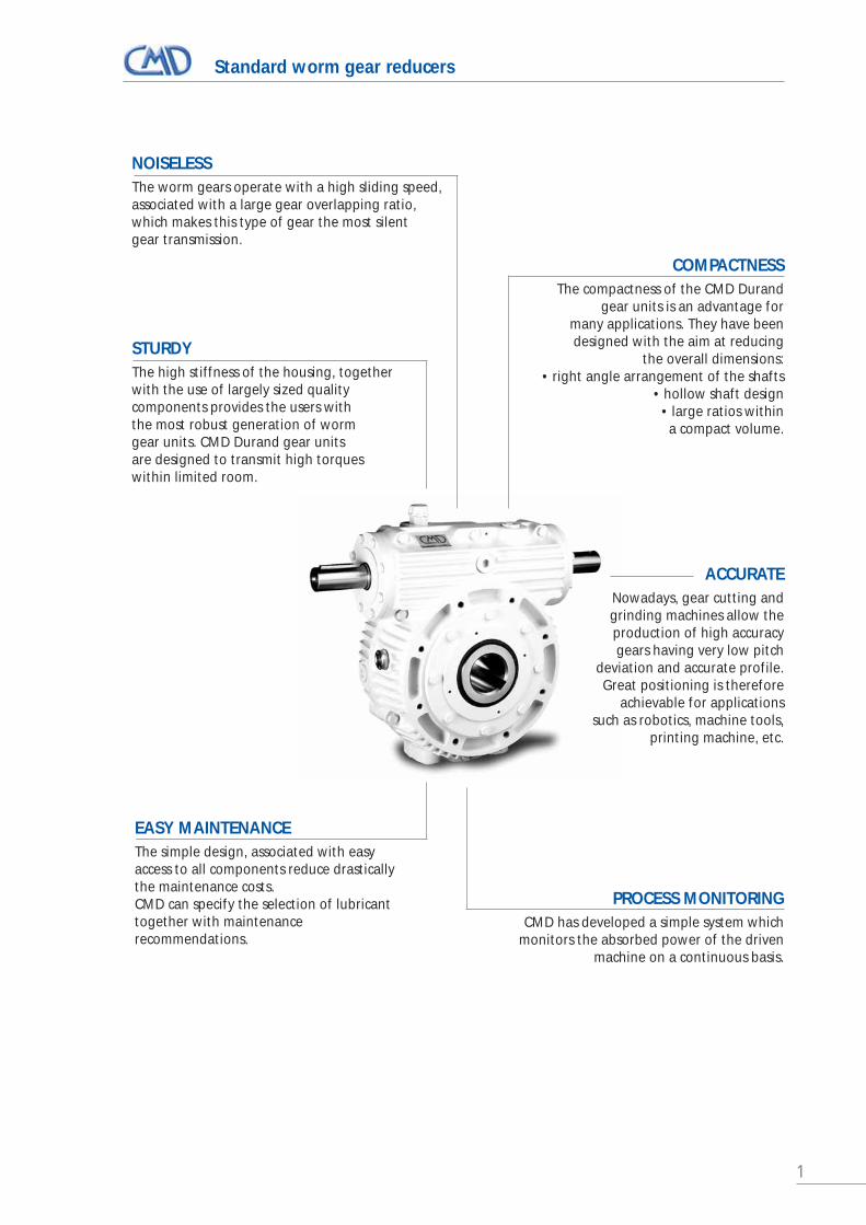
STURDYThe high stiffness of the housing, togetherwith the use of largely sized qualitycomponents provides the users with the most robust generation of worm gear units. CMD Durand gear units are designed to transmit high torqueswithin limited room.
NOISELESSThe worm gears operate with a high sliding speed,associated with a large gear overlapping ratio,which makes this type of gear the most silent gear transmission.
EASY MAINTENANCEThe simple design, associated with easyaccess to all components reduce drasticallythe maintenance costs.CMD can specify the selection of lubricanttogether with maintenancerecommendations.
COMPACTNESSThe compactness of the CMD Durand
gear units is an advantage for many applications. They have been designed with the aim at reducing
the overall dimensions:• right angle arrangement of the shafts
• hollow shaft design• large ratios within
a compact volume.
ACCURATENowadays, gear cutting andgrinding machines allow theproduction of high accuracygears having very low pitch
deviation and accurate profile.Great positioning is therefore
achievable for applicationssuch as robotics, machine tools,
printing machine, etc.
PROCESS MONITORINGCMD has developed a simple system which
monitors the absorbed power of the drivenmachine on a continuous basis.
Standard worm gear reducers
2
Summary
Generalities and Design . . . . . . . . . . . . . . . . . . . . . . . . . . . . . . . . . . . . . . . . . . . . . . . . . . . . . . . . . . . . . . . . . . p. 3-4
Reducer type selection according to gear ratio . . . . . . . . . . . . . . . . . . . . . . . . . . . . . . . . . . . . . . . . . . . . . . . . p. 5
N range and JUMBOFLEX – Selection method sizes from 160 to 1250 . . . . . . . . . . . . . . . . . . . . . . . . . . . . . . p. 6
Service factor – Classification of machines . . . . . . . . . . . . . . . . . . . . . . . . . . . . . . . . . . . . . . . . . . . . . . . . . . . . p. 7
Reversibility and self-locking . . . . . . . . . . . . . . . . . . . . . . . . . . . . . . . . . . . . . . . . . . . . . . . . . . . . . . . . . . . . . . . p. 8
Selection method - Example . . . . . . . . . . . . . . . . . . . . . . . . . . . . . . . . . . . . . . . . . . . . . . . . . . . . . . . . . . . . . . . . p. 9
Sizes 160 F/C to 500 F/C – Mechanical rating and thermal capacity . . . . . . . . . . . . . . . . . . . . . . . . . . . . . p. 11-13
Overall dimensions sizes from 160 to 500 F/C Type . . . . . . . . . . . . . . . . . . . . . . . . . . . . . . . . . . . . . . . . . . . p. 14
Multi reduction reducers . . . . . . . . . . . . . . . . . . . . . . . . . . . . . . . . . . . . . . . . . . . . . . . . . . . . . . . . . . . . . . . . . . p. 15
JUMBOFLEX – Mechanical rating and thermal capacity . . . . . . . . . . . . . . . . . . . . . . . . . . . . . . . . . . . . . . . p. 17-19
JUMBOFLEX overall dimension F Type . . . . . . . . . . . . . . . . . . . . . . . . . . . . . . . . . . . . . . . . . . . . . . . . . . . . . . p. 20
JUMBOFLEX overall dimension MH1 Type . . . . . . . . . . . . . . . . . . . . . . . . . . . . . . . . . . . . . . . . . . . . . . . . . . . p. 21
JUMBOFLEX overall dimension MH2 Type . . . . . . . . . . . . . . . . . . . . . . . . . . . . . . . . . . . . . . . . . . . . . . . . . . . p. 22
Torque arm . . . . . . . . . . . . . . . . . . . . . . . . . . . . . . . . . . . . . . . . . . . . . . . . . . . . . . . . . . . . . . . . . . . . . . . . . . . . . p. 24
Base kits . . . . . . . . . . . . . . . . . . . . . . . . . . . . . . . . . . . . . . . . . . . . . . . . . . . . . . . . . . . . . . . . . . . . . . . . . . . . . . . p. 25
Dynamometric shock absorbers . . . . . . . . . . . . . . . . . . . . . . . . . . . . . . . . . . . . . . . . . . . . . . . . . . . . . . . . . . . . p. 26
Hollow shaft with shrink rim assembly . . . . . . . . . . . . . . . . . . . . . . . . . . . . . . . . . . . . . . . . . . . . . . . . . . . . . . p. 27
Gear motors . . . . . . . . . . . . . . . . . . . . . . . . . . . . . . . . . . . . . . . . . . . . . . . . . . . . . . . . . . . . . . . . . . . . . . . . . . . . p. 28
Maximum admissible torque Co . . . . . . . . . . . . . . . . . . . . . . . . . . . . . . . . . . . . . . . . . . . . . . . . . . . . . . . . . . . . p. 29
Mounting – Installation – Lubrication – Commissioning . . . . . . . . . . . . . . . . . . . . . . . . . . . . . . . . . . . . . . . . p. 30
Reducers – Requested information for inquiries . . . . . . . . . . . . . . . . . . . . . . . . . . . . . . . . . . . . . . . . . . . . . . . p. 31
Data and application . . . . . . . . . . . . . . . . . . . . . . . . . . . . . . . . . . . . . . . . . . . . . . . . . . . . . . . . . . . . . . . . . . . p. 33-37
Worm gear sets – Requested information for inquiries . . . . . . . . . . . . . . . . . . . . . . . . . . . . . . . . . . . . . . . . . p. 38
Main machine tools . . . . . . . . . . . . . . . . . . . . . . . . . . . . . . . . . . . . . . . . . . . . . . . . . . . . . . . . . . . . . . . . . . . . . . p. 39
Applications . . . . . . . . . . . . . . . . . . . . . . . . . . . . . . . . . . . . . . . . . . . . . . . . . . . . . . . . . . . . . . . . . . . . . . . . . . p. 41-52

3
Generalities and Design
The CMD Durand technology is constantly evolving and being optimised, thanks to several decades of experience incooperation with the end users.
CMD is considered as a specialist for medium and large size of worm gears and offers a wide range of worm gearboxesthat complies with very demanding industrial applications: metal, sugar, cement, waste recycling, environment, materialhandling, machine tools industries…
Whenever the standard range is not adapted, CMD can modify the standard design or provide a custom design to com-ply with specific requirements: high accuracy, high torques, specific dimensions, specific kinematic design…
This catalogue describes in details the N series, from size 160 to 500, the type F or FN (hollow output shaft) and the typeC or FNC (solid output shaft) as well as the range of large reducers JUMBOFLEX sizes 550 to 1250.
Large reduction ratios are made possible by combining several reducers.
Various accessories such as reaction torque arms, temperature sensors, torque and load sensors, couplings… are availableto adapt the standard units to customer’s requirements.
Method of selection, mechanical and thermal nominal ratings are given for N series reducers.
For customers that will to integrate worm gear set in their machine, we recommend that selection is made using catalo-gue center distance and ratio. However, CMD also manufacture specific centre distance and gear ratio in order to meetspecific requirements – please consult CMD.
GEARSCMD Durand as a specialist of worm gears, hasselected the A profile (DIN3975) for optimising thelength of contact, Hertz contact pressures and lubri-cation.
The torque rating is calculated in accordance withBS721-Durand standard.
Thermal rating is calculated in consideration of thedesign parameters and the performances of lubri-cants that have been tested on CMD Durand testbench.
The worm shaft is made of alloyed steel forgings, itsthreads are case carburised and ground on CNCmachines of the latest generation, warranting veryhigh accuracy.
The worm wheel teeth are made of high mechani-cal properties and low friction bronze.
Gear contact pattern is simulated on computer inorder to optimise the oil film thickness and theadaptation of the teeth surfaces under load fromthe very first running hours.
HOUSINGThe very compact housings are made of high qua-lity cast iron GSL, GJS or cast steel GE 280 for speci-fic applications.
Robust design allows the unit to withstand highinternal and external loads. The internal arrange-ment of the housing insures automatic lubricationof bearings.
The housing allows multiple position mountingand accommodates various optional items.
BEARINGSCMD Durand has a long experience in using rollerbearings that withstand the thrust loads generatedby worm gears. These bearings are also selected towithstand the external loads (radial, axial…) thatvary from one application to another. The selectionof bearings and their mounting arrangementinsure optimal gear meshing.
LUBRICATIONCMD Durand has tested both test bench and at sitea large number of synthetic and mineral oils whichresults have been used to determine the ratingsgiven in this catalogue.
CMD Durand gear units that are lubricated by syn-thetic Polyglycol oils offer the highest performan-ces in terms of transmitted power, efficiency anddurability. For most of applications, splashing lubri-cation is sufficient enough.
For applications which require oil circulation andinjection, CMD provides a complete lubricationsystem inclusive of pumps, monitoring and accesso-ries.
Because of the running position of the reducer anddue to low speed operation, bearings are some-times lubricated by EP grease.
Note: CMD Durand provides general or specific lubrica-tion instructions.

4
Generalities and Design
SEALINGJoint sealants compatible with Polyglycol syntheticoils are used for sealing joint faces.
The sealing of the rotating parts is performed bystandard Nitrile or Viton seal rings.
COUPLINGSCMD Durand worm gearboxes can be fitted withflexible grid couplings Winflex 9000 and/or Flexi-dent crown gear couplings.
CMD catalogues for couplings are available uponrequest.
ACCESSORIES AND OPTIONSNumerous accessories and optional items can besupplied to fit our CMD Durand reducers, such as:
• special hollow shaft• double output shaft with standard or custom
dimension• shrink disk arrangement for hollow shaft• reaction torque arm• shock absorber (with safety switch)• torque, temperature sensors etc…• backstop, free wheel• lubrication system with accessories• mechanical fan, heat exchanger• flange for motors• special centre distance and gear ratios
Winflex
Flexident
QUALITY CONTROLAll our products benefit from the followingpermanent checking:
• raw material / bought in material inspection• incoming goods inspection• manufacturing inspections• gear teeth contact pattern inspection• final dimensional inspection• final inspection with running test• protective packing in accordance
with ISO 9001:2000
CETI
M P
hoto
- C.
Bar
ret

5
Reducer type selection according to gear ratio uSingle unit or multi reduction units
5 N range
7.5 F/C Type
10 Jumboflex
12.5
15
20 N range
25 MHF1, MHC1 Type
30 N range Jumboflex
40 u = from 5 to 60 F/C Type
50 Overall dimensions Jumboflex
60 refer to page 14 and 20
80
u = from 15 to 230 N range
F/C Type
180 Overall dimensions Jumboflex
refer to page 21 and 22
225
230 u = from 25 to 3600MHF2, MHC2 Type
Primary MH1
Overall dimensionsJumboflex
refer to page 15
u = from 50 to 800 u = from 80 to 18000
800
3600 Primary MH2
10800
u = from 225 to 48000
48000
Reducers (1) to (4): available sizes from 160 to 1250, option for gear motorsFor selection of Reducers (2) (3) (4) consult CMDReversibility and self-locking class refer to page 8
u Worm reducer (1) Multi reduction MH reducer (3) Multi reductionworm reducers (2) worm reducers + MH (4)

6
Worm gear units N range and JUMBOFLEX from sizes 160 to 1250
1. Selection of the gear ratiou= High Speed shaft rotation speed, N1 (HS) / LowSpeed shaft rotation speed, N2 (LS).
The rating selection tables, pages 11-13 and 17-19,provide the standard gear ratios.
u = N1 / N2Note: for final selection of gear ratio, it is required to check thatthe reversibility condition is in conformity with the applicationpage 8.
2. Selection of the service factor SFThe service factor SF is determined according tothe application and the service conditions. For alarge number of application, SF is calculated on thetables provided on page 7.
SF = FA x FH x FL x FD
3. Calculation of the required torquerating
The required torque rating Mts equals thetransmitted torque M2 multiplied by the servicefactor SF:
Mts = M2 x SF
4. Reducer size selectionSelect in the mechanical ratings table the standardratio which is the closest to the calculated ratioobtained in 1.
On the line corresponding to the chosen gear ratioand to the input speed N1, select the size of thereducer having a torque rating Mt2 equals to, orhigher than the calculated torque (paragraph 3).Check that the following condition is fulfilled:
Mt2 ≥ Mts
5. Checking of reducer thermal powerThe thermal power of the running reducer equalsthe absorbed power time series of factors providedpage 7.
Pths = Pa x FT x FM x FP
Allowable thermal power Pth is given on the lowertable of the page corresponding to selected reducerpage 4.
On the line corresponding to the chosen gear ratiou and to the input speed N1, check the value of Pth(without fan), Pthv (with fan) or Pthc (with lubrica-tion circuit), and verify that:
Pth ≥ PthsPthv ≥ Pths (N range)
Pthc ≥ Pths (Jumboflex)
6. Checking of maximum permissible torqueThe maximum permissible peak torque Co at theoutput shaft of the reducer, inclusive of inertias,must be higher than the maximum peak torque ofthe application M2maxi.
Co > M2maxiNote: In the specific case of power transmission using several reducerssimultaneously, it is recommended to apply a correction factorFr that takes into account the unequal load sharing on eachreducer (example: travel drive, cranes…).
Fr = 1.15 to 1.3 in case of drive with 2 to 4 reducers.
Fr = 1.3 to 1.6 in case of drive with more than 4 reducers.

7
Service factor - Classification of machines
SERVICE FACTOR SF FOR MECHANICAL RATING SELECTION SF = FA x FH x FL x FD
THERMAL RATING FACTORS
Screw conveyors – Belt or bucket conveyors with uni-form loading – Light elevators – Travel drive for machinetools – Shearing press driving gears – Sheet cutting dri-ves – Generators – Packing machines – Mixers for lightliquids or homogeneous materials – Light centrifugalpumps – Fans.
Calanders – Heavy centrifugal machines – Main drivesfor machine tools – Belt or bucket conveyors with non-uniform loading, for instance mixed materials – Heavyelevators – Cranes slewing drives – Extruders – Rotarykilns – Strip mills (continuous mill for zinc plates, alumi-nium angle bars and plates) – Mixers for heavy liquids ornon-homogeneous materials – Centrifugal pumps – Pro-cessing pumps – Piston pumps – Industrial and miningfans.
Light ball mills – Lifting gears – Rubber extruders – Bloo-ming mills – Wood processing machines (multiple bladesawing machines, rough turning machines) – Intermit-tent operation mixers for rubber and plastic materials –Single cylinder pumps.
Roller mills – Heavy vertical mills – Pellet wheel drives –Mining screens – Quarry and mining crushers – Dredges –Bucket elevators – Heavy plates shearing machines – Peeling machines – Cold rolling mills – Heavy drillingmachines – Steel processing machines – Heavy rubbermixers – Heavy processing pumps – Brick extruders –Bucket wheels.
Ambient temperature factor FT
is related to the ambient temperature and type of lubricant
Operating position factor FP
is related to the position of the high speedshaft and the output shaft relatively to theground.
Loading cycle factor FM
is related to the ratio:% = (total operation time under load during one cycle /
total cycle time) x 100
Ambient temp.°C 0 10 20 30 40 50
Oil type
Synthetic oil FT 0.78 0.87 1 1.16 1.40 1.75PolyGlycol
Mineral oil EP FT 1 1.14 1.33 1.60 2 2.70
Service Driven conditions machines
Uniform
U
Medium shocks
M
Heavy shocks
H
Light shocks
L
% 100 80 60 40 20FM 1 0.90 0.80 0.70 0.60
Reducerposition
FP 1 1 1 1.15 1.25
S G D I V
Hours U L M H3≤h<8 0.8 1 1.25 1.508≤h≤12 1 1.25 1.50 1.75h>12 1.25 1.50 1.75 2
Application factor FA
Daily duty cycles
Starts/h 10 100 200 300 400FD 1 1.1 1.15 1.2 1.3
Starting condition factor FD
Number of starts or reversings per hour
Required FH
Required FH
service life service life8000 h 0.70 50000 h 1.2510000 h 0.75 75000 h 1.4325000 h 1 100000 h 1.57
Life factor FH
Synthetic oil PolyGlycol 1
Mineral oil EP 1.25
Lubrificant factor FL

8
Reversibility and self-locking
Operating as a speed reducer:The worm shaft is driving the wheel connected to the driven machine. The power is transmitted bythe worm shaft to the wheel.
Operating as speed increaser:The worm wheel is driving and transmit power tothe worm shaft.
Reversibility:This property is applicable for both directions ofrotation. Operation as speed increaser in this case ispossible. Reversibility allows the driven load tobecome the driving element (for instance, slowingdown an heavy inertia machine).
Self-locking:This property is applicable for both direction of rota-tion. Operation as speed increaser in this case isimpossible. Self locking prevents the driven loadfrom becoming a driving element: this safety condi-tion is required for lifting application (for instance).
In stopped condition the self-locking is called “staticself-locking” whereas in running conditions is called“dynamic self-locking”.
In case of dynamic self-locking, if the driven loadbecomes the driving element, the reducer will stoprunning, immediately or after a very short while,depending on the resisting torques in the drivechain. The complete dynamic self-locking conditionis practically never reached, unless in the specificcase of high ratios and speeds close to zero.
Maximum thread angle for each reversibility class, depending on reduction ratio and centre distance.
Class u / size 160 200 250 315 400 450 500
15 39 41 41
7.5 29 31 31 34 41 39 41
10 23 24 26 28 31 32 31
212.5 19 21 20 23 26 29 27
15 16 17 16 20 22 24 24
20 12 13 13 15 17 18 18
325 9 9 10 12 14 14 14
30 8 9 8 10 11 13 12
4 40 6 6 7 8 8 9 9
550 4 5 5 6 7 8 8
60 4 4 4 5 6 6 7
Reversibility class table
Class # Definition
1Full static and dynamic reversibility
2Static and dynamic reversibility Fast reverse effect
Poor static reversibility 3 Dynamic reversibility
Fast reverse effect under vibrations
Static self-locking 4 Fast reverse effect under vibrations
Poor dynamic reversibility (*)
Static self-locking
5 Fast reverse effect under vibrationsVery poor dynamic reversibility (*)
Reversibility classThe table below is to be used for the selection of the gear ratio of the reducer which is required to fulfil the reversibility or self-locking condition. For specific cases, please consult CMD.
EfficiencyFor a given ratio, the efficiency increases with the size ofthe gearbox, the sliding velocity (worm shaft speed) andthe lead angle. Polyglycol synthetic oil also providesoptimum efficiency.
The efficiency ηr of the reducer lubricated with synthe-tic polyglycol lubricant can be estimated as follows:
Mt2 output torque (N.m)N2 output shaft rotation (rpm)P1 input power on worm shaft (kW)
Note: for standard applications where reversibility is required, we recommend classes 1 and 2. When full static self-locking is required,select classes 4 and 5 and install a safety brake. For multi reduction reducers, the reversibility ability of the whole drive is achievedif all reducers are reversible. The self-locking ability is achieved if the larger unit is self-locking (preferably, the smaller units shouldbe self-locking as well).
(*) relative to worm shaft rotation (low speed) ♦ for larger sizes, consult CMD
ηR = Mt2.N2
9550.P1

9
Selection method – Example of selection
Example:• application: conveyor drive
• 24h continuous duty, uniform load
• ambient temperature 30°C
• motor rating 55 kW @ 1500 rpm
• output shaft rotation N2 = 47 rpm
• absorbed power Pa = 52 kW @ 1480 rpm
• efficiency η = 0.93
• output torque M2 = 9830 Nm
• required life 50000 hrs
• maximum output peak torque M2 maxi = 25000 Nm
• operating position: S (the worm shaft is horizontal, above the worm wheel)
• lubricant: Polyglycol synthetic oil PG
1) Gear ratio uu = N1 / N2 = 1480 / 47 = 31.5
Select exact ratio 30 refer to page 12
(Standard gear ratio refer to page 29)
2) Service factor SFSF = FA x FH x FL x FD
FA = 1.25 FH = 1.25 FL = 1 FD = 1
SF = 1.25 x 1.25 x 1 x 1 = 1.56
3) Selection torqueMts = M2 x SF = 9830 x 1.56 = 15 335 Nm
4) Sizing of the reducerSelect the size of the reducer from the mechanicalpower ratings table, on pages 11 to 13.
For u = 30 and N1= 1500, the size 315 is selected,on page 12.
The condition Mt2>MTs is fulfilled.
5) Thermal power ratingThe required thermal rating is
Pths = Pa x FT x FM x FP
Facteurs FT = 1.16 FM = 1 FP =1
Pths = 52 x 1.16 x 1 x 1 = 60.3 kW
The power rating is indicated in the table on thebottom of page 12. The thermal rating for gearbox315, ratio 30 is Pthv = 62 kW @ 1500 rpm with fan.
The condition Pthv>Pths is fulfilled.
6) Verification of the maximum peak torque on the output shaft: Co
Refer to Co table on page 29: for unit size 315 andgear ratio 30, the maximum admissible peak torqueCo is 51130 Nm which is higher than the required25000 Nm.
The condition Co>M2maxi is fulfilled.

10

11
Worm gear units N range sizes 160 F/C to 500 F/C Type
Mechanical power ratings P1 in kW, Output torque Mt2 in Nm, worm shaft rotation speed N1 and worm wheel rotation speed N2 in rpm,Service factor = 1, design life = 25000 h, polyglycol synthetic oil, Fp = 1, FM = 1.
Size 160 200 250 315 400 450 500Ratio u N1 N2 P1 Mt2 P1 Mt2 P1 Mt2 P1 Mt2 P1 Mt2 P1 Mt2 P1 Mt2
1800 360 57 1 524 101 2 687 160 4 237 265 7 825 1500 300 52 1 664 92 2 938 146 4 646 243 8 584 1200 240 46 1 843 82 3 260 130 5 167 216 9 548 1000 200 42 1 996 74 3 536 118 5 612 196 10 369
5 750 150 36 2 250 63 3 992 100 6 351 167 11 731 500 100 28 2 637 50 4 689 79 7 480 131 13 771 375 75 23 2 906 41 5 175 66 8 271 109 15 230 200 40 15 3 535 27 6 315 43 10 130 72 18 656 50 10 5.8 5 185 10 9 308 17 15 021 24 24 253
1800 240 51 2 017 88 3 482 146 5 703 247 9 120 480 17 701 595 24 125 837 32 945 1500 200 46 2 188 79 3 782 133 6 208 225 9 968 438 19 380 543 26 404 766 36 136 1200 160 41 2 407 70 4 167 117 6 856 200 11 035 390 21 530 483 29 342 683 40 260 1000 133.3 37 2 593 63 4 495 106 7 408 180 11 946 353 23 339 437 31 797 620 43 804
7.5 750 100 31 2 905 53 5 044 90 8 333 153 13 458 299 26 343 370 35 861 527 49 553 500 66.7 24 3 336 41 5 805 69 9 623 119 15 631 233 30 668 288 41 641 410 57 732 375 50 20 3 659 34 6 376 57 10 590 99 17 237 194 33 874 239 45 983 342 63 884 200 26.7 13 4 413 22 7 710 38 12 855 65 21 004 127 41 395 157 56 172 225 78 335 50 6.7 4.7 6 284 8.3 11 028 14 18 512 24 30 500 35 44 071 44 60 546 59 79 414
1800 180 41 2 178 72 3 778 140 6 978 229 12 035 402 21 067 575 29 010 613 32 130 1500 150 37 2 355 65 4 090 127 7 571 207 13 070 365 22 955 523 31 657 558 35 112 1200 120 33 2 580 57 4 488 112 8 330 183 14 388 322 25 320 464 35 029 496 38 955 1000 100 30 2 774 51 4 831 101 8 977 165 15 518 290 27 339 418 37 860 448 42 190
10 750 75 25 3 070 43 5 355 84 9 998 138 17 264 243 30 476 351 42 325 377 47 203 500 50 19 3 510 33 6 136 65 11 496 106 19 871 188 35 163 272 48 945 292 54 706 375 37 16 3 839 27 6 720 54 12 619 88 21 824 156 38 678 225 53 912 243 60 339 200 20 10 4 606 18 8 084 35 15 243 57 26 391 102 46 904 148 65 547 159 73 544 50 5 3.7 6 439 6.5 11 349 13 21 588 21 37 378 35 61 670 50 85 875 59 105 493
1800 144 38 2 356 70 4 393 111 7 123 195 12 187 349 23 651 529 33 316 587 41 265 1500 120 34 2 542 63 4 746 100 7 706 176 13 212 316 25 683 480 36 250 534 44 949 1200 96 30 2 783 56 5 200 88 8 448 155 14 518 278 28 172 424 39 921 471 49 534 1000 80 27 2 972 50 5 560 79 9 044 139 15 565 249 30 215 380 42 867 423 53 263
12.5 750 60 22 3 283 41 6 150 66 10 024 116 17 285 208 33 572 318 47 712 354 59 367 500 40 17 3 746 32 7 030 50 11 484 89 19 852 160 38 580 245 54 945 274 68 487 375 30 14 4 091 26 7 687 42 12 576 74 21 773 132 42 330 203 60 365 227 75 322 200 16 9.2 4 897 17 9 220 27 15 125 48 26 262 86 51 093 132 73 040 148 91 316 50 4 3.4 6 777 6.2 12 806 10 21 081 18 36 816 29 66 921 47 100 702 54 128 555
Thermal power ratings Pth (without cooling fan), Pthv (with cooling fan) in kW, ambient T° 20°C, polyglycol synthetic oil.
Size 160 200 250 315 400 450 500Ratio u N1 N2 Pth Pthv Pth Pthv Pth Pthv Pth Pthv Pth Pthv Pth Pthv Pth Pthv
1800 360 31 49 48 77 78 124 119 190 1500 300 29 47 47 74 76 120 116 185 1200 240 28 40 44 64 72 105 112 162 1000 200 26 35 42 57 70 94 108 145
5 750 150 24 30 39 48 65 79 101 123 500 100 21 23 34 38 57 63 90 99 375 75 19 20 31 32 52 54 82 85 200 40 16 16 25 25 43 43 67 67 50 10 10 10 16 16 27 27 42 42
1800 240 26 41 42 66 68 109 113 180 185 294 221 352 253 402 1500 200 25 40 40 64 66 105 110 175 181 288 217 345 250 397 1200 160 23 34 38 55 63 91 106 152 175 252 210 303 243 351 1000 133.3 22 30 36 49 60 81 101 136 169 227 203 273 237 318
7.5 750 100 20 25 33 41 56 68 94 115 158 193 190 232 224 274 500 66.7 18 20 29 32 49 54 84 92 141 155 171 188 203 223 375 50 16 17 27 28 45 47 77 80 130 134 157 163 187 194 200 26.7 13 13 22 22 37 37 62 62 106 106 128 128 154 154 50 6.7 9 9 14 14 24 24 40 40 67 67 81 81 97 97
1800 180 22 35 35 56 60 95 98 156 165 262 205 327 222 354 1500 150 21 33 34 54 58 92 95 151 160 255 201 319 219 348 1200 120 20 28 32 46 55 80 90 131 154 222 194 280 212 307 1000 100 19 25 30 41 53 71 87 117 148 199 187 251 206 277
10 750 75 17 21 28 34 49 59 80 98 138 169 175 214 194 237 500 50 15 16 25 27 43 47 71 78 123 135 157 172 176 193 375 37 14 14 22 23 39 41 65 68 113 117 144 149 162 168 200 20 11 11 18 18 32 32 53 53 92 92 117 117 133 133 50 5 7.4 7.4 12 12 21 21 34 34 59 59 75 75 85 85
1800 144 19 30 31 50 50 80 86 136 142 227 189 300 188 298 1500 120 18 29 30 48 48 77 83 132 138 220 184 292 184 293 1200 96 17 24 28 41 46 66 79 114 133 192 177 255 179 258 1000 80 16 22 27 36 44 59 76 102 127 171 170 229 173 232
12.5 750 60 15 18 25 30 41 50 70 86 119 145 159 194 163 199 500 40 13 14 22 24 36 40 62 69 106 116 142 156 147 161 375 30 12 12 20 21 33 34 57 59 97 100 130 135 135 140 200 16 9.7 9.7 16 16 27 27 47 47 79 79 106 106 111 111 50 4 6.5 6.5 11 11 18 18 30 30 51 51 68 68 71 71
Note: P1 is the absorbed power on the worm shaft, for transmitting Mt2 on the low speed shaft.
Oil spray lubrication
Consult CMD
Consult CMD

12
Worm gear units N range sizes 160 F/C to 500 F/C Type
Mechanical power ratings P1 in kW, Output torque Mt2 in Nm, worm shaft rotation speed N1 and worm wheel rotation speed N2 in rpm,Service factor = 1, design life = 25000 h, polyglycol synthetic oil, Fp = 1, FM = 1.
Size 160 200 250 315 400 450 500Ratio u N1 N2 P1 Mt2 P1 Mt2 P1 Mt2 P1 Mt2 P1 Mt2 P1 Mt2 P1 Mt2
1800 120 31 2 406 55 4 252 99 7 666 174 13 577 267 20 886 466 35 113 611 47 644 1500 100 28 2 592 49 4 585 90 8 281 157 14 673 241 22 629 422 38 142 553 51 752 1200 80 24 2 813 43 4 982 78 9 021 138 15 997 211 24 708 370 41 739 485 56 674 1000 66.7 22 2 999 38 5 318 70 9 647 123 17 117 189 26 469 331 44 760 434 60 795
15 750 50 18 3 305 32 5 869 58 10 674 102 18 956 158 29 360 277 49 725 363 67 566 500 33.3 14 3 760 24 6 689 45 12 204 79 21 696 121 33 670 213 57 132 280 77 670 375 25 11 4 099 20 7 301 37 13 348 65 23 745 100 36 895 176 62 677 231 85 235 200 13.3 7.4 4 888 13 8 727 24 16 015 42 28 525 65 44 425 115 75 632 151 102 911 50 3.3 2.7 6 677 4.7 11 963 9 22 097 15 39 436 24 61 645 35 88 778 43 112 843
1800 90 25 2 533 50 5 059 80 8 104 132 13 585 257 26 389 373 37 210 477 49 245 1500 75 23 2 711 45 5 420 71 8 696 118 14 592 231 28 429 336 40 152 430 53 167 1200 60 20 2 936 39 5 878 62 9 448 103 15 870 202 30 972 294 43 784 376 58 042 1000 50 18 3 126 35 6 265 56 10 084 92 16 950 180 33 124 263 46 857 336 62 137
20 750 37.5 15 3 437 29 6 899 46 11 125 77 18 722 150 36 654 219 51 902 280 68 859 500 25 11 3 899 22 7 840 35 12 675 59 21 358 116 41 910 168 59 416 216 78 872 375 18.8 9.2 4 244 18 8 543 29 13 831 49 23 326 95 45 838 139 65 034 178 86 360 200 10 6.1 5 103 12 10 294 19 16 715 32 28 235 63 55 653 90 78 139 117 105 071 50 2.5 2.2 6 796 4.3 13 756 6.9 22 438 11 37 998 19 64 404 29 96 324 35 120 835
1800 72 23 2 760 41 5 077 72 9 005 114 14 392 227 29 021 343 43 856 371 47 689 1500 60 20 2 950 37 5 435 65 9 654 102 15 440 204 31 168 309 47 257 334 51 371 1200 48 18 3 192 32 5 888 57 10 476 89 16 768 178 33 874 269 51 438 291 55 909 1000 40 16 3 395 29 6 271 50 11 170 79 17 890 158 36 162 241 54 975 260 59 747
25 750 30 13 3 729 24 6 898 42 12 308 66 19 730 132 39 912 200 60 774 216 66 039 500 20 10 4 223 18 7 829 32 13 998 51 22 464 101 45 488 154 69 402 166 75 402 375 15 8 4 592 15 8 524 27 15 259 42 24 504 83 49 651 127 75 847 137 82 395 200 8 5.4 5 464 10 10 167 18 18 245 27 29 337 54 59 512 83 91 123 89 98 968 50 2 2 7 269 3.6 13 579 6.4 24 463 10 39 414 19 80 102 30 123 100 32 133 654
1800 60 19 2 722 34 4 882 58 8 459 111 16 487 199 29 963 290 41 253 338 51 270 1500 50 17 2 906 30 5 217 52 9 061 99 17 672 178 32 185 261 44 377 304 55 220 1200 40 15 3 138 26 5 641 45 9 823 87 19 174 156 34 958 227 48 245 265 60 106 1000 33.3 13 3 333 23 5 999 40 10 467 77 20 443 139 37 300 203 51 514 237 64 206
30 750 25 11 3 653 19 6 585 34 11 521 64 22 522 115 41 139 169 56 873 197 70 926 500 16.7 8.4 4 127 15 7 454 26 13 087 49 25 610 89 46 843 129 64 841 151 80 920 375 12.5 6.9 4 481 12 8 101 21 14 254 41 27 913 73 51 100 107 70 789 125 88 382 200 6.7 4.5 5 283 8 9 573 14 16 901 27 33 139 47 60 764 69 84 517 81 105 335 50 1.7 1.7 7 003 2.9 12 737 4.7 20 839 9 40 904 15 72 037 24 111 763 27 131 659
Thermal power ratings Pth (without cooling fan), Pthv (with cooling fan) in kW, ambient T° 20°C, polyglycol synthetic oil.
Size 160 200 250 315 400 450 500Ratio u N1 N2 Pth Pthv Pth Pthv Pth Pthv Pth Pthv Pth Pthv Pth Pthv Pth Pthv
1800 120 16 25 26 42 42 67 75 119 130 207 165 263 195 310 1500 100 15 24 25 40 41 65 73 116 126 201 161 257 190 303 1200 80 14 21 24 35 39 56 69 100 121 174 155 224 183 265 1000 66.7 14 18 23 31 37 50 66 89 116 156 149 201 177 238
15 750 50 13 15 21 26 34 42 61 75 108 132 139 170 165 202 500 33.3 11 12 19 20 30 33 54 60 96 106 124 137 148 163 375 25 10 10 17 18 28 29 50 52 88 91 114 118 136 141 200 13.3 8.3 8.3 14 14 23 23 41 41 72 72 93 93 111 111 50 3.3 5.6 5.6 9.3 9.3 15 15 27 27 47 47 60 60 72 72
1800 90 12 20 21 33 34 54 59 94 102 163 135 214 159 253 1500 75 12 19 20 31 33 52 57 91 99 158 131 209 155 246 1200 60 11 16 19 27 31 45 55 79 95 137 126 182 149 215 1000 50 11 14 18 24 30 40 52 70 92 123 121 163 143 193
20 750 37.5 9.7 12 16 20 28 34 49 59 85 104 113 138 134 164 500 25 8.6 9.4 14 16 24 27 43 47 76 83 101 111 120 132 375 18.8 7.8 8.1 13 14 22 23 39 41 70 72 92 96 110 114 200 10 6.5 6.5 11 11 18 18 32 32 57 57 76 76 90 90 50 2.5 4.5 4.5 7.5 7.5 12 12 22 22 38 38 49 49 59 59
1800 72 9.7 15 16 25 27 43 48 77 90 143 108 172 139 220 1500 60 9.3 15 15 24 26 42 47 74 87 138 105 168 135 215 1200 48 8.8 13 15 21 25 36 45 64 83 120 101 146 129 187 1000 40 8.4 11 14 19 24 32 43 57 80 107 97 131 125 167
25 750 30 7.7 9.5 13 16 22 27 40 48 74 90 91 111 116 142 500 20 6.9 7.6 11 13 20 22 35 39 66 72 81 89 104 114 375 15 6.3 6.6 10 11 18 19 32 34 60 63 75 77 95 99 200 8 5.3 5.3 8.7 8.7 15 15 27 27 50 50 61 61 78 78 50 2 3.7 3.7 6 6 10 10 18 18 33 33 41 41 51 51
1800 60 9.2 15 15 24 23 36 40 64 73 116 101 160 112 178 1500 50 8.8 14 15 23 22 35 39 62 71 113 98 156 109 173 1200 40 8.3 12 14 20 21 30 37 54 68 98 94 135 105 151 1000 33.3 7.9 11 13 18 20 27 36 48 65 88 90 121 101 136
30 750 25 7.3 8.9 12 15 19 23 33 41 61 74 84 103 95 116 500 16.7 6.5 7.1 11 12 17 18 30 33 54 60 75 83 85 93 375 12.5 5.9 6.2 10 10 15 16 27 28 50 52 69 72 78 81 200 6.7 5 5 8.2 8.2 13 13 23 23 41 41 57 57 64 64 50 1.7 3.5 3.5 5.7 5.7 8.8 8.8 15 15 28 28 38 38 43 43
Note: P1 is the absorbed power on the worm shaft, for transmitting Mt2 on the low speed shaft.
Oil spray lubrication

13
Reducer DURAND N range
Mechanical power ratings P1 in kW, Output torque Mt2 in Nm, worm shaft rotation speed N1 and worm wheel rotation speed N2 in rpm,Service factor = 1, design life = 25000 h, polyglycol synthetic oil, Fp = 1, FM = 1.
Size 160 200 250 315 400 450 500Ratio u N1 N2 P1 Mt2 P1 Mt2 P1 Mt2 P1 Mt2 P1 Mt2 P1 Mt2 P1 Mt2
1800 45 14 2 620 28 5 249 48 9 070 85 16 259 140 27 366 204 39 229 263 51 953 1500 37.5 13 2 793 25 5 603 43 9 694 76 17 403 126 29 370 183 42 173 236 55 879 1200 30 11 3 013 22 6 050 38 10 483 67 18 851 109 31 853 160 45 776 206 60 731 1000 25 10 3 198 20 6 428 33 11 150 59 20 074 98 33 949 143 48 819 184 64 791
40 750 18.8 8.3 3 501 16 7 045 28 12 239 49 22 075 81 37 382 119 53 803 153 71 441 500 12.5 6.4 3 949 13 7 959 21 13 856 38 25 045 62 42 478 91 61 205 117 81 319 375 9.4 5.4 4 325 10 8 726 18 15 211 32 27 534 52 46 723 76 67 438 98 89 544 200 5 3.5 4 987 6.8 10 080 12 17 610 20 31 957 33 54 327 49 78 500 63 104 315 50 1.3 1.3 6 605 2.5 13 391 4.3 23 486 7.6 42 796 10 60 618 15 86 289 19 114 282
1800 36 13 2 888 23 5 249 42 9 492 67 15 632 117 27 737 187 44 607 235 55 706 1500 30 12 3 076 21 5 598 37 10 138 60 16 707 104 29 688 168 47 891 212 59 928 1200 24 10 3 314 18 6 040 33 10 955 52 18 068 91 32 136 146 51 907 185 65 241 1000 20 9.1 3 515 16 6 413 29 11 644 47 19 215 81 34 201 130 55 297 165 69 601
50 750 15 7.6 3 842 14 7 022 24 12 771 39 21 092 67 37 580 109 60 845 138 76 741 500 10 5.9 4 327 11 7 923 19 14 441 30 23 875 52 42 591 83 69 077 106 87 342 375 7.5 4.9 4 693 8.7 8 604 16 15 701 25 25 977 43 46 376 69 75 297 88 95 356 200 4 3.2 5 407 5.7 9 935 10 18 173 16 30 102 27 53 816 44 87 547 57 111 181 50 1 1.2 7 151 2.2 13 189 3.8 24 220 6. 40 198 10 72 036 16 117 565 21 149 999
1800 30 11 2 780 20 5 171 36 9 447 69 18 713 112 31 289 159 44 786 151 42 809 1500 25 10 2 959 18 5 512 32 10 084 61 19 986 100 33 460 142 47 986 135 45 932 1200 20 8.5 3 186 16 5 943 28 10 888 53 21 596 87 36 182 124 51 932 118 49 738 1000 16.7 7.6 3 377 14 6 306 25 11 567 48 22 954 78 38 478 110 55 261 105 52 950
60 750 12.5 6.4 3 688 12 6 899 21 12 676 40 25 173 65 42 232 92 60 706 87 58 204 500 8.3 5.0 4 171 9.0 7 818 16 14 396 31 28 614 50 48 053 71 69 148 67 66 350 375 6.3 4.1 4 466 7.5 8 381 13 15 452 25 30 729 41 51 635 58 74 350 55 71 375 200 3.3 2.7 5 143 4.9 9 673 8.7 17 878 16 35 590 26 59 871 37 86 315 35 82 933 50 0.8 0.9 5 740 1.6 11 065 3.0 20 978 5.4 40 890 9.3 75 693 14 114 933 13 110 592
> 60
Thermal power ratings Pth (without cooling fan), Pthv (with cooling fan) in kW, ambient T° 20°C, polyglycol synthetic oil.
Size 160 200 250 315 400 450 500Ratio u N1 N2 Pth Pthv Pth Pthv Pth Pthv Pth Pthv Pth Pthv Pth Pthv Pth Pthv
1800 45 6.7 11 11 18 19 31 31 50 55 88 72 114 86 137 1500 37.5 6.4 10 11 17 19 30 30 49 54 85 70 112 84 133 1200 30 6.1 8.8 10 15 18 26 29 42 51 74 67 97 81 117 1000 25 5.8 7.8 10 13 17 23 28 38 50 67 65 87 78 105
40 750 18.8 5.4 6.6 9.1 11 16 19 26 32 46 57 61 74 73 89 500 12.5 4.8 5.3 8.2 9.0 14 15 23 26 42 46 55 60 66 72 375 9.4 4.5 4.6 7.5 7.8 13 13 22 22 38 40 50 52 61 63 200 5 3.8 3.8 6.3 6.3 11 11 18 18 32 32 42 42 50 50 50 1.3 2.8 2.8 4.5 4.5 7.7 7.7 13 13 22 22 28 28 34 34
1800 36 6 8.7 9 14 15 24 27 43 49 78 59 95 64 102 1500 30 5.3 8.4 8.6 14 15 23 26 41 47 75 58 92 63 100 1200 24 5 7.2 8.2 12 14 20 25 36 45 65 56 80 61 88 1000 20 4.8 6.5 7.9 11 13 18 24 32 44 59 54 72 59 79
50 750 15 4.5 5.4 7.3 9 13 15 22 27 41 50 50 62 56 68 500 10 4 4.40 6.6 7.2 11 12 20 22 37 40 45 50 50 55 375 7.5 3.7 3.9 6.1 6.3 10 11 18 19 34 35 42 43 47 49 200 4 3.2 3.2 5.2 5.2 8.8 8.8 16 16 28 28 35 35 39 39 50 1 2.4 2.4 3.8 3.8 6.4 6.4 11 11 20 20 24 24 27 27
1800 30 4.6 7.4 7.5 12 13 20 23 36 42 66 52 83 64 102 1500 25 4.5 7.1 7.3 12 12 20 22 35 40 64 51 81 62 99 1200 20 4.3 6.2 7 10 12 17 21 30 39 56 49 71 60 87 1000 16.7 4.1 5.5 6.7 9 11 15 20 27 37 50 47 64 58 78
60 750 12.5 3.8 4.7 6.2 7.6 11 13 19 23 35 43 44 54 54 66 500 8.3 3.4 3.8 5.6 6.2 9.6 11 17 19 31 35 40 44 49 54 375 6.3 3.2 3.30 5.2 5.4 8.9 9.2 16 16 29 30 37 38 45 47 200 3.3 2.8 2.8 4.5 4.5 7.6 7.6 13 13 24 24 31 31 38 38 50 0.8 2.1 2.1 3.4 3.4 5.6 5.6 9.6 9.6 17 17 22 22 26 26
> 60
Note: P1 is the absorbed power on the worm shaft, for transmitting Mt2 on the low speed shaft.
Oil spray lubrication
Multi reduction reducers – MH type reducers
Consult CMD
Multi reduction reducers – MH type reducers
Consult CMD

14
WEIGHT (kg)
Type F Type C
130 150
200 250
325 385
500 625
950 1145
1365 1575
1850 2135
Overall dimensions sizes from 160 to 500 F/C Type
SIZE a C D E F G H** J K K1 L N* P* Q* R S T
160 F&C 160 190 98 305 245 312 187 148 122 300 160 103 234 310 8 M16 270
200 F&C 200 226 102 345 295 352 226 165 135 330 190 114 285 380 8 M16 325
250 F&C 250 283 128 425 355 432 272 188 155 390 220 134 326 470 8 M20 395
315 F&C 315 352 143 480 420 487 328 225 185 470 260 160 326 500 12 M20 400
400 F&C 400 442 170 590 560 597 408 250 210 550 300 185 385 710 12 M24 630
450 F&C 450 503 200 660 620 667 435 290 250 590 340 225 385 800 12 M30 710
500 F&C 500 555 200 710 670 717 485 325 280 650 350 245 440 900 12 M30 800
Position Designation
1 Housing
2 Worm wheel
3 Worm shaft
4 Bearings
SIZE b b1 c c1 e e1 f f1 g h h1 j k l m n p p1
160 F&C 110 50 40 40 35 35 12 12 70 240 140 20 200 20 62.5 40 M12 M12
200 F&C 110 60 50 50 44.5 44.5 14 14 90 265 140 20 230 25 81 50 M12 M12
250 F&C 140 70 60 60 53 53 18 18 110 305 170 20 270 28 100 60 M14 M14
315 F&C 140 80 70 70 62.5 62.5 20 20 140 365 210 20 330 36 128 75 M16 M16
400 F&C 170 140 90 70 81 62.5 25 20 160 415 250 10 400 40 147 100 M16 M16
450 F&C 210 170 110 90 100 81 28 25 160 495 250 10 480 40 147 100 M16 M16
500 F&C 210 170 110 90 100 81 28 25 180 555 300 10 530 45 165 120 M20 M20
* Mounting bases dimensions.** Dimension H indicates the overall dimension when there is no second shaft extension.Other dimensions of low speed shaft are possible upon request. C type reducer is a F type reducer having the hollow shaft filled up with solid shaft.
b1 b
G
H **H **
EF
Da
C
J
N*N*
K
Ø P
*
Ø Q
*
N* N*
K1K1
Ø P
*
Ø Q
*
L L h1*h1
J
ø g
h6
X
X Z
Z
Bore diameter ø T
R holes, diam. S, threaded depth 2S
e1
c1 h
6
f1 P8
f P8
e
c h6
l P8
n
j k
h
g h6
g h6
l P8
setio
se
tio
setio
Customer shaft
setio
1 hole Ø p1
2 holes Ø p1
1 hole Ø p
1 hole Ø p
Type F Type C
1
4
3
2

15
Multi reduction reducers
A E H U T a a’ b c e f p g m l p2 Weight (kg)
80 U-160F275 177.5 187 370 450 160 80 60 25 21 8 M8 60 53 18 M12
160
80 U-160C 180
100 U-200F330 217.5 226 440 546 200 100 80 30 26 8 M8 70 62.5 20 M12
240
100 U-200C 290
125 U-250F390 275 272 510 680 250 125 110 40 35 12 M10 90 81 25 M14
390
125 U-250C 450
160 F-315F470 305 328 618 857 315 160 110 40 35 12 M12 110 100 28 M16
640
160 F-315C 765
200 F-400F560 345 408 725 1068 400 200 110 50 44.5 14 M12 140 128 36 M16
1165
200 F-400C 1360
200 F-450F590 345 435 755 1179 450 200 110 50 44.5 14 M12 140 128 36 M16
1590
200 F-450C 1800
250 F-450F615 425 435 803 1236 450 250 140 60 53 18 M14 140 128 36 M16
1720
250 F-450C 1930
200 F-500F645 345 485 810 1281 500 200 110 50 44.5 14 M12 160 147 40 M20
2085
200 F-500C 2370
250 F-500F665 425 485 853 1338 500 250 140 60 53 18 M14 160 147 40 M20
2215
250 F-500C 2500
a
T
E
U
AH
a
b
Y'
Y'
VV
Y'
Y'
ef P8
Ø Ç
h6
Section V
1 hole Ø p2
mI P8
Ø g
h6
Section Y'
1 hole Ø p

16

17
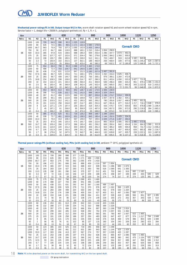
JUMBOFLEX Worm Reducer
Oil spray lubrication
Mechanical power ratings P1 in kW, Output torque Mt2 in Nm, worm shaft rotation speed N1 and worm wheel rotation speed N2 in rpm,Service factor = 1, design life = 25000 h, polyglycol synthetic oil, Fp = 1, FM = 1.
Size 560 630 710 800 900 1000 1120 1250Ratio u N1 N2 P1 Mt2 P1 Mt2 P1 Mt2 P1 Mt2 P1 Mt2 P1 Mt2 P1 Mt2 P1 Mt2
1500 150 906 43.9 1 190 57.7 1200 160 809 49.0 1 064 64.5 1000 133.3 735 53.4 967 70.3 1 330 96.7
7.5 750 100 626 60.5 824 79.8 1 137 110.2 1 553 150.5 500 66.7 488 70.6 644 93.2 890 129.0 1 219 176.8 1 588 240.3 375 50 407 78.2 537 103.3 743 143.2 1 018 196.5 1 327 267.2 200 26.7 269 96.0 355 127.1 492 176.6 676 242.8 882 330.7 1 207 451.9 1 669 625.9 50 6.7 101 140.8 134 186.8 186 260.4 256 359.3 334 489.6 459 672.0 636 933.9 684 1 065.9 10 1.3 29 194.0 37 249.5 51 339.7 68 458.7 90 631.0 104 728.6 141 993.2 142 1 065.9
1500 150 921 57.9 1 242 78.2 1200 120 819 64.4 1 106 87.0 1000 100 742 69.9 1 002 94.5 1 223 122.2
10 750 75 625 78.3 845 106.2 1 034 137.5 1 503 200.1 500 50 486 91.0 658 123.5 805 160.0 1 172 233.4 1 614 321.8 375 37.5 404 100.5 547 136.4 670 177.0 976 258.3 1 345 356.7 200 20 265 122.8 360 166.9 441 216.7 643 317.0 889 438.6 1 174 546.8 1 540 764.8 50 5 99 176.8 134 240.9 164 312.5 239 458.5 331 636.7 440 800.3 576 1 117.7 766 1 489.9 10 1 25 213.6 34 292.3 42 380.8 58 528.5 80 737.3 97 847.7 121 1 124.4 161 1 503.8
1500 120 826 64.6 1 083 84.9 1200 96 732 71.5 961 94.0 1 324 129.7 1000 80 659 77.2 865 101.6 1 194 140.3 1 654 194.6
12.5 750 60 554 86.3 728 113.7 1 008 157.6 1 399 219.1 500 40 429 99.8 565 131.8 783 182.9 1 088 254.9 1 379 323.2 375 30 356 110.0 469 145.3 650 202.0 905 281.7 1 147 357.7 1 554 479.3 200 16 234 133.9 308 177.1 428 246.7 596 344.7 757 438.6 1 026 589.3 1 393 801.5 50 4 86 190.2 113 252.0 158 352.2 220 493.6 280 630.1 381 850.4 517 1 160.1 689 1 549.5 10 0.8 24 249.3 32 342.6 45 479.9 63 674.2 78 835.8 94 1 000.9 130 1 388.4 199 2 138.5
Thermal power ratings Pth (without cooling fan), Pthv (with cooling fan) in kW, ambient T° 20°C, polyglycol synthetic oil.
Size 560 630 710 800 900 1000 1120 1250Ratio u N1 N2 Pth Pthc Pth Pthc Pth Pthc Pth Pthc Pth Pthc Pth Pthc Pth Pthc Pth Pthc
1500 150 307 906 394 1 190 1200 160 301 809 388 1 064 1000 133.3 294 735 380 967 497 1 330 750 100 279 626 362 824 477 1 137 625 1 553
7.5 500 66.7 255 488 332 644 440 890 580 1 219 744 1 588 375 50 236 407 308 537 410 743 542 1 018 698 1 327 200 26.7 195 269 255 355 341 492 453 676 587 882 753 1 207 975 1 669 50 6.7 123 101 161 134 216 186 287 256 373 334 480 459 624 636 808 855 10 1.3 78 29 101 39 134 54 177 74 229 97 292 129 378 176 487 178
1500 150 274 921 356 1 242 1200 120 267 819 349 1 106 1000 100 261 742 341 1 002 437 1 223 750 75 247 625 325 845 418 1 034 554 1 503
10 500 50 225 486 296 658 383 805 511 1 172 666 1 614 375 37.5 208 404 274 547 356 670 476 976 623 1 345 200 20 171 265 227 360 295 441 396 643 522 889 685 1 174 867 1 540 50 5 109 99 144 134 188 164 252 239 332 331 437 440 555 576 734 766 10 1 70 28 91 38 119 47 158 69 206 96 269 122 340 151 447 201
1500 120 238 826 312 1 083 1200 96 232 732 305 961 401 1 324 1000 80 226 659 297 865 393 1 194 519 1 654 750 60 214 554 283 728 375 1 008 499 1 399
12.5 500 40 194 429 258 565 344 783 460 1 088 598 1 379 375 30 180 356 238 469 320 650 428 905 559 1 147 719 1 554 200 16 148 234 197 308 265 428 357 596 468 757 606 1 026 793 1 393 50 4 95 86 126 113 169 158 228 220 299 280 388 381 509 517 675 689 10 0.8 61 25 81 32 108 45 144 63 187 80 241 110 314 149 414 199
Note: P1 is the absorbed power on the worm shaft, for transmitting Mt2 on the low speed shaft.
Consult CMD
Consult CMD
18
JUMBOFLEX Worm Reducer
Oil spray lubrication
Mechanical power ratings P1 in kW, Output torque Mt2 in Nm, worm shaft rotation speed N1 and worm wheel rotation speed N2 in rpm,Service factor = 1, design life = 25000 h, polyglycol synthetic oil, Fp = 1, FM = 1.
Size 560 630 710 800 900 1000 1120 1250Ratio u N1 N2 P1 Mt2 P1 Mt2 P1 Mt2 P1 Mt2 P1 Mt2 P1 Mt2 P1 Mt2 P1 Mt2
1500 100 709 64.0 998 90.3 1 325 119.9 1200 80 626 70.5 881 99.5 1 171 132.3 1 590 179.8 1000 66.7 563 75.9 793 107.3 1 055 142.9 1 433 194.4 750 50 472 84.7 666 119.9 888 160.1 1 210 218.4 1 654 298.9
15 500 33.3 365 97.8 515 138.6 688 185.4 939 253.4 1 286 347.7 1 673 452.2 375 25 303 107.7 427 152.6 571 204.4 780 279.6 1 069 384.2 1 393 500.5 200 13.3 198 130.7 280 185.5 375 249.0 512 341.1 703 469.7 919 613.8 1 182 843.9 50 3.3 72 183.9 102 261.5 137 352.1 188 483.9 258 668.4 339 877.6 435 1 205.2 629 1 587.6 10 0.7 19 218.3 25 306.6 30 423.4 49 590.3 68 832.2 97 1 185.8 120 1 568.3 145 1 737.1
1500 75 554 66.0 798 95.3 1 068 127.6 1 460 174.8 1200 60 488 72.4 703 104.7 941 140.5 1 289 192.7 1000 50 438 77.9 631 112.8 847 151.5 1 160 207.9 1 497 281.9 750 37.5 366 86.7 529 125.6 711 169.1 976 232.8 1 262 316.3 1 625 406.7
20 500 25 283 99.7 408 144.7 550 195.2 756 269.1 978 366.1 1 264 472.9 375 18.8 234 109.5 338 159.0 455 214.7 627 296.3 811 403.4 1 050 522.0 1 427 711.0 200 10 153 132.4 221 192.4 298 260.4 411 359.9 539 496.3 699 644.2 951 879.1 1 395 1 151.0 50 2.5 56 183.4 80 266.9 108 362.4 149 502.4 193 685.0 252 893.3 343 1 222.5 510 1 633.2 10 0.5 16 240.7 22 342.2 31 476.5 43 667.9 54 891.5 72 1 201.7 99 1 648.0 124 1 872.3
1500 60 453 68.9 613 93.6 842 128.7 1 132 173.5 1 506 230.9 1200 48 398 75.6 539 102.7 741 141.5 998 190.9 1 329 254.5 1000 40 357 81.2 484 110.5 666 152.3 897 205.8 1 196 274.7 1 614 359.9 750 30 299 90.1 405 122.8 558 169.8 754 230.0 1 007 307.8 1 362 404.1
25 500 20 230 103.5 312 141.1 431 195.5 583 265.2 780 355.8 1 057 468.5 1 465 651.0 375 15 191 113.5 258 154.8 357 214.7 483 291.6 647 391.6 877 516.2 1 217 718.1 1 648 976.0 200 8 125 137.1 170 187.4 235 260.4 318 354.3 426 476.7 579 630.6 803 878.8 1 089 1 196.4 50 2 45 187.1 61 256.0 85 356.9 115 487.0 154 657.3 209 872.0 290 1 218.5 394 1 663.1 10 0.4 13 246.2 18 338.0 24 472.4 33 646.0 44 874.3 53 1 017.2 73 1 429.0 100 1 965.1
1500 50 385 67.3 525 92.1 718 126.2 958 168.7 1 298 229.0 1200 40 338 73.7 461 100.9 631 138.5 843 185.4 1 144 252.0 1 429 324.3 1000 33.3 303 79.0 413 108.4 567 149.0 757 199.6 1 029 271.6 1 287 350.0 750 25 253 87.6 345 120.3 475 165.7 636 222.6 865 303.9 1 085 392.5 1 485 572.6
30 500 16.7 195 100.4 266 137.9 366 190.4 491 256.2 669 350.4 842 454.6 1 154 664.3 1 580 912.8 375 12.5 161 110.0 220 151.2 303 208.9 406 281.3 554 385.2 699 500.4 958 731.7 1 312 1 006.2 200 6.7 105 131.9 144 181.5 198 251.3 266 339.1 363 465.2 457 605.0 626 883.3 858 1 216.7 50 1.7 38 179.6 52 247.5 72 343.7 96 464.9 132 639.8 167 835.7 228 1 222.1 313 1 687.8 10 0.3 11 234.6 15 324.4 21 452.1 28 612.8 38 845.5 48 1 107.1 66 1 618.3 91 2 239.5
Thermal power ratings Pth (without cooling fan), Pthv (with cooling fan) in kW, ambient T° 20°C, polyglycol synthetic oil.
Size 560 630 710 800 900 1000 1120 1250Ratio u N1 N2 Pth Pthc Pth Pthc Pth Pthc Pth Pthc Pth Pthc Pth Pthc Pth Pthc Pth Pthc
1500 100 219 709 289 998 377 1 325 1200 80 213 626 282 881 371 1 171 488 1 590 1000 66.7 207 563 275 793 362 1 055 479 1 433 750 50 196 472 261 666 345 888 459 1 210 597 1 654
15 500 33.3 178 365 237 515 316 688 422 939 553 1 286 683 1 673 375 25 164 303 219 427 293 571 393 780 516 1 069 641 1 393 200 13.3 135 198 181 280 243 375 327 512 431 703 540 919 682 1 182 50 3.3 87 72 116 102 156 137 209 188 276 258 347 339 439 435 635 629 10 0.7 57 21 75 29 100 39 133 54 174 74 217 97 274 125 391 180
1500 75 175 554 232 798 304 1 068 401 1 460 1200 60 170 488 227 703 299 941 395 1 289 1000 50 165 438 221 631 292 847 387 1 160 486 1 497 750 37.5 156 366 209 529 278 711 370 976 467 1 262 568 1 625
20 500 25 142 283 190 408 254 550 340 756 432 978 530 1 264 375 18.8 131 234 176 338 236 455 316 627 403 811 497 1 050 650 1 427 200 10 108 153 146 221 196 298 264 411 337 539 419 699 550 951 827 1 395 50 2.5 70 56 94 80 127 108 170 149 218 193 272 252 357 343 534 510 10 0.5 47 16 62 23 83 31 110 43 140 55 173 72 226 99 333 146
1500 60 136 453 181 613 239 842 315 1 132 403 1 506 1200 48 132 398 177 539 234 741 310 998 399 1 329 1000 40 129 357 173 484 229 666 304 897 393 1 196 518 1 614 750 30 122 299 164 405 219 558 292 754 379 1 007 501 1 362
25 500 20 111 230 150 312 200 431 269 583 351 780 467 1 057 610 1 465 375 15 103 191 139 258 186 357 250 483 328 647 437 877 574 1 217 764 1 648 200 8 85 125 115 170 155 235 209 318 276 426 369 579 486 803 649 1 089 50 2 56 45 76 61 102 85 137 115 180 154 240 209 316 290 423 394 10 0.4 38 13 51 18 67 24 90 33 117 44 155 60 202 83 268 113
1500 50 123 385 164 525 216 718 285 958 367 1 298 1200 40 120 338 160 461 212 631 280 843 363 1 144 425 1 429 1000 33.3 117 303 156 413 207 567 274 757 357 1 029 420 1 287 750 25 110 253 148 345 197 475 263 636 343 865 407 1 085 506 1 485
30 500 16.7 100 195 135 266 181 366 242 491 318 669 380 842 475 1 154 631 1 580 375 12.5 93 161 125 220 168 303 225 406 297 554 357 699 447 958 596 1 312 200 6.7 77 105 104 144 140 198 188 266 249 363 302 457 380 626 508 858 50 1.7 51 38 69 52 92 72 124 96 163 132 199 167 251 228 335 313 10 0.3 35 11 46 15 62 21 82 28 107 38 130 48 163 66 216 91
Note: P1 is the absorbed power on the worm shaft, for transmitting Mt2 on the low speed shaft.
Consult CMD
Consult CMD

19
JUMBOFLEX Worm Reducer
Oil spray lubrication
Consult CMD
Consult CMD
Mechanical power ratings P1 in kW, Output torque Mt2 in Nm, worm shaft rotation speed N1 and worm wheel rotation speed N2 in rpm,Service factor = 1, design life = 25000 h, polyglycol synthetic oil, Fp = 1, FM = 1.
Size 560 630 710 800 900 1000 1120 1250Ratio u N1 N2 P1 Mt2 P1 Mt2 P1 Mt2 P1 Mt2 P1 Mt2 P1 Mt2 P1 Mt2 P1 Mt2
1500 37.5 322 78.9 427 105.3 590 130.2 819 181.2 1 047 243.7 1 347 312.4 1200 30 282 86.3 374 115.3 518 142.5 719 198.7 921 267.5 1 187 343.7 1000 25 253 92.5 336 123.7 464 153.1 646 213.5 826 287.8 1 067 370.4 1 483 516.7 750 18.8 211 102.3 281 137.1 388 169.8 541 237.4 693 320.8 898 414.3 1 249 578.8 1 687 784.5
40 500 12.5 163 117.0 216 156.8 299 194.5 417 272.4 535 368.5 695 477.8 969 669.5 1 311 909.9 375 9.4 136 128.8 181 172.9 247 213.0 345 298.6 448 408.5 582 530.7 813 744.3 1 100 1 012.5 200 5 88 150.9 116 202.6 160 253.1 223 355.4 287 480.7 374 626.2 521 879.8 706 1 198.6 50 1.3 33 205.0 43 275.8 59 344.9 82 485.6 105 658.3 137 861.7 191 1 213.8 258 1 657.8 10 0.3 8 219.7 12 323.3 15 379.4 20 540.3 26 718.8 35 992.4 50 1 417.3 68 1 976.6
1500 30 278 78.4 376 106.8 508 144.6 689 196.8 908 260.0 1 059 329.4 1 509 416.7 1200 24 244 85.6 330 116.7 446 158.3 605 215.7 798 285.5 932 362.2 1 329 458.5 1000 20 218 91.6 296 125.1 400 169.9 543 231.7 717 307.0 838 390.0 1 194 493.9 1 561 648.5 750 15 182 101.2 247 138.3 335 188.5 455 257.7 602 342.5 705 435.8 1 005 552.4 1 315 726.1
50 500 10 141 115.5 190 158.0 258 215.7 352 295.3 465 393.4 551 507.0 778 637.2 1 020 839.8 375 7.5 117 126.3 158 172.9 214 236.2 292 323.8 386 431.8 452 549.8 647 702.0 849 926.1 200 4 75 147.7 102 202.4 138 277.1 188 380.4 249 508.3 292 648.6 416 828.6 545 1 094.7 50 1 28 200.2 38 274.8 52 377.5 70 519.7 93 696.5 109 889.1 150 1 108.6 201 1 510.1 10 0.2 8.4 256.9 11 353.7 15 487.1 21 672.2 27 903.4 29 1029.6 34 1 108.6 46 1 548.5
1500 25 227 75.5 306 102.8 416 139.9 563 190.1 757 256.4 899 325.7 1 198 435.8 1 581 577.4 1200 20 199 82.3 268 112.2 365 152.9 494 208.0 664 281.0 791 357.7 1 054 479.2 1 393 635.8 1000 16.7 178 88.0 240 120.1 327 164.0 442 223.2 596 301.9 710 384.7 947 516.0 1 252 685.3 750 12.5 149 97.0 201 132.6 273 181.5 370 247.7 500 336.1 597 429.3 797 576.5 1 054 766.8
60 500 8.3 115 111.1 155 151.9 212 208.4 287 284.9 388 387.2 463 494.7 620 666.3 821 888.7 375 6.3 95 119.9 127 164.0 174 225.1 236 308.0 318 419.1 380 536.1 509 722.8 674 964.8 200 3.3 61 140.0 82 191.7 112 263.6 152 361.4 205 492.6 246 631.6 329 853.0 436 1 140.3 50 0.8 23 188.3 31 258.2 42 356.2 57 489.6 77 669.5 92 859.5 123 1 164.0 163 1 560.1 10 0.2 6.9 240.8 9.2 331.4 13 458.9 17 632.2 23 866.7 28 1116.1 37 1 514.9 49 2 034.7
Thermal power ratings Pth (without cooling fan), Pthv (with cooling fan) in kW, ambient T° 20°C, polyglycol synthetic oil.
Size 560 630 710 800 900 1000 1120 1250Ratio u N10 N2 Pth Pthc Pth Pthc Pth Pthc Pth Pthc Pth Pthc Pth Pthc Pth Pthc Pth Pthc
1500 37.5 82 322 110 427 182 590 241 819 300 1 047 355 1 347 1200 30 80 282 107 374 178 518 237 719 296 921 353 1 187 1000 25 78 253 105 336 174 464 232 646 290 826 348 1 067 453 1 483 750 18.8 74 211 100 281 165 388 221 541 279 693 337 898 440 1 249 583 1 687
40 500 12.5 68 163 92 216 151 299 203 417 257 535 314 695 412 969 549 1 311 375 9.4 63 136 85 181 140 247 189 345 240 448 294 582 387 813 518 1 100 200 5 53 88 72 116 117 160 159 223 202 287 249 374 329 521 442 706 50 1.3 36 33 49 43 78 59 105 82 134 105 166 137 219 191 293 258 10 0.3 26 10 34 13 53 17 71 24 90 30 111 40 145 56 192 75
1500 30 75 278 99 376 130 508 172 689 222 908 248 1 059 399 1 509 1200 24 73 244 97 330 128 446 169 605 220 798 247 932 397 1 329 1000 20 71 218 94 296 125 400 166 543 217 717 244 838 393 1 194 519 1 561 750 15 67 182 90 247 120 335 159 455 209 602 237 705 381 1 005 506 1 315
50 500 10 62 141 82 190 110 258 147 352 194 465 223 551 356 778 475 1 020 375 7.5 57 117 77 158 103 214 138 292 182 386 210 452 335 647 448 849 200 4 48 75 65 102 87 138 117 188 155 249 180 292 285 416 383 545 50 1 33 28 44 38 59 52 79 70 105 93 123 109 191 154 256 201 10 0.2 24 8 31 11 42 15 55 21 72 27 85 33 128 42 170 58
1500 25 66 227 88 306 116 416 153 563 198 757 222 899 286 1 198 373 1 581 1200 20 64 199 86 268 113 365 151 494 196 664 221 791 285 1 054 374 1 393 1000 16.7 63 178 84 240 111 327 148 442 192 596 219 710 283 947 371 1 252 750 12.5 59 149 80 201 106 273 142 370 185 500 212 597 275 797 363 1 054
60 500 8.3 54 115 73 155 98 212 131 287 172 388 199 463 259 620 343 821 375 6.3 51 95 68 127 91 174 123 236 161 318 187 380 245 509 325 674 200 3.3 43 61 58 82 77 112 104 152 137 205 161 246 211 329 280 436 50 0.8 30 23 40 31 53 42 71 57 94 77 111 92 145 123 192 163 10 0.2 22 7 29 9 38 13 50 17 66 23 77 28 100 37 132 49
Gear ratio > 60 consult CMD
Note: P1 is the effective power on the high speed shaft (worm) for transmitting the torque T2 to low speed shaft.
20
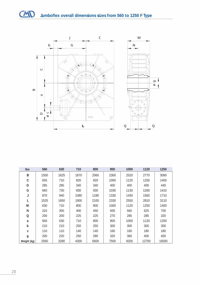
Jumboflex overall dimensions sizes from 560 to 1250 F Type
Size 560 630 710 800 900 1000 1120 1250
B 1500 1625 1870 2060 2300 2520 2770 3090
C 655 710 820 920 1000 1120 1250 1400
D 285 285 340 340 400 400 400 440
G 660 730 830 930 1030 1130 1260 1410
J 870 940 1080 1180 1330 1430 1560 1710
L 1525 1650 1900 2100 2330 2550 2810 3110
M 630 710 800 900 1000 1120 1250 1400
N 315 355 400 450 500 560 625 700
Q 200 200 225 225 270 285 285 320
a 560 630 710 800 900 1000 1120 1250
b 210 210 250 250 300 300 300 300
c 110 110 140 140 160 160 180 180
g 200 220 250 280 320 360 400 450
Weight (kg) 2560 3280 4300 5600 7500 9200 12700 16500
ø g
M
N
B
Ca
D
ø c
LL
b G
J C
Q Q

21
Jumboflex overall dimensions sizes from 560 to 1250 MH1 Type
Size 560 630 710 800 900 1000 1120 1250
B 1545 1670 1910 2100 2350 2570 2890 3170
C 655 710 820 920 1000 1120 1250 1400
D 330 330 380 380 450 450 520 520
G 840 940 1000 1090 1230 1330 1470 1620
J 980 1080 1160 1250 1400 1500 1680 1830
L 1635 1790 1980 2170 2800 2620 2930 3230
M 630 710 800 900 1000 1120 1250 1400
N 315 355 400 450 500 560 625 700
Q 300 300 345 345 450 450 520 520
a 560 630 710 800 900 1000 1120 1250
a’ 250 250 315 315 400 400 500 500
b 140 140 160 160 170 170 210 210
c 70 70 80 80 90 90 110 110
g 200 220 250 280 320 360 400 450
Weight (kg) 3000 3800 5000 6500 8500 11000 13750 18000
ø c
B
Ca
D
L
CJ
ø g
M
N
Q
a’
Q
b G
22
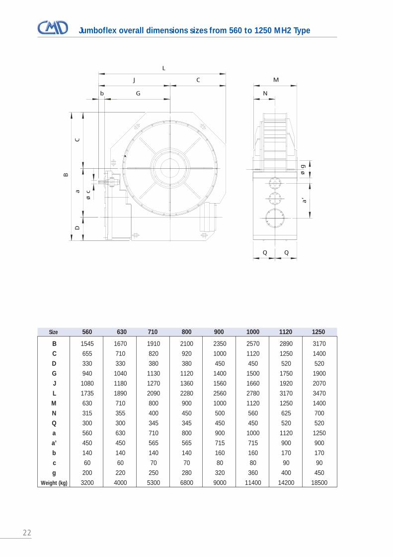
Jumboflex overall dimensions sizes from 560 to 1250 MH2 Type
Size 560 630 710 800 900 1000 1120 1250
B 1545 1670 1910 2100 2350 2570 2890 3170
C 655 710 820 920 1000 1120 1250 1400
D 330 330 380 380 450 450 520 520
G 940 1040 1130 1120 1400 1500 1750 1900
J 1080 1180 1270 1360 1560 1660 1920 2070
L 1735 1890 2090 2280 2560 2780 3170 3470
M 630 710 800 900 1000 1120 1250 1400
N 315 355 400 450 500 560 625 700
Q 300 300 345 345 450 450 520 520
a 560 630 710 800 900 1000 1120 1250
a’ 450 450 565 565 715 715 900 900
b 140 140 140 140 160 160 170 170
c 60 60 70 70 80 80 90 90
g 200 220 250 280 320 360 400 450
Weight (kg) 3200 4000 5300 6800 9000 11400 14200 18500
N
M
Q Q
a’
ø g
Gb
J C
L
Da
C
B
ø c

23

24
Reaction torque arm – Reducers sizes from 160 to 500, F Type
Size G H J SO SI SII DO DI
160 F 12 400 109 • •
200 F 12 500 120 • • •
250 F 12 630 140 • • •
315 F 20 800 170 • • •
400 F 20 1000 195 • • •
450 F 20 1120 235 • • •
500 F 20 1250 255 • • •
A B C D E F
SO/DO 35 30 30 25 30 20
SI/DI 50 40 35 30 30 25
SII 60 50 50 40 40 30
J
H 0
.5
J
H 0
.5H
0.5
AB
D
C
G
F-0.5
E+
0.2
2
0
-0.1
J
SO, SI, SII Type (N range)
DO, DI Type (N range)

25
Base kits – Reducers sizes from 160 to 500, C Type
Size B C C1 C2 D D1 F F1 F2 F3
160C 250 320 350 370 400 280 320 240 110200C 330 400 400 450 450 300 350 270 110250C 420 500 500 560 560 350 390 320 140315C 480 630 630 710 710 440 500 400 165400C 480 600 800 800 900 900 530 560 440 200450C 670 900 900 1000 1000 600 630 530500C 620 750 1000 1000 1120 1120 670 710 590 225
Size G G1 H1 H2 H3 H4 J K L M N
160C 326 370 220 300 165 100 17 234 280 340 15200C 350 400 260 340 200 115 17 285 370 430 15250C 410 450 310 420 230 125 21 326 440 500 20315C 500 580 400 500 270 140 25 475 560 640 25400C 610 640 475 630 360 160 25 600 700 800 25450C 700 750 560 710 400 180 32 670 800 900 30500C 750 790 600 750 420 200 32 750 900 1000 30
(1) 4 holes ØJ for sizes 160 to 3158 holes ØJ for sizes 400 to 500
(2) 4 holes ØJ for sizes 160 to 2508 holes ØJ for sizes 315 to 500
D
C1
C if 8 holes
G
F
NH2`0
.5
B
(1)
NN
H3`0
.5
H3
H3
(2)
nL
nK
D
C1
H1`0
.5
C if 8 holes
N
G
F
B
(1)
G1
H4`0
.5
F2
F1
C if 8 holes
C1
D1
F3
(1)
for 160C to 560C ST type R type
I type V and W type
26
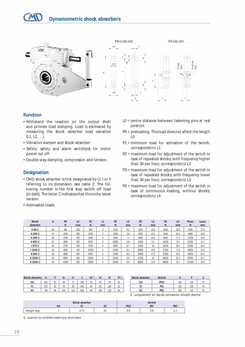
Dynamometric shock absorbers
Function • Withstand the reaction on the output shaft
and provide load damping. Load is estimated bymeasuring the shock absorber load variation (L1, L2, …).
• Vibration damper and shock absorber.
• Safety: safety and alarm switch(es) for motorpower cut off.
• Double way damping: compression and tension.
Designation• CMD shock absorber is first designated by O, I or II
referring to its dimension, see table 2. The fol-lowing number is the first step switch off load (in daN). The letter C indicates that this is the latestversion.
• Admissible loads
L0 = centre distance between fastening pins at restposition
P0 = preloading. This load does not affect the lengthL0
P1 = minimum load for activation of the switch, corresponds to L1
P2 = maximum load for adjustment of the switch incase of repeated shocks, with frequency higherthan 30 per hour, corresponds to L2
P3 = maximum load for adjustment of the switch incase of repeated shocks, with frequency lowerthan 30 per hour, corresponds to L3
P4 = maximum load for adjustment of the switch incase of continuous loading, without shocks,corresponds to L4
Shock Q P0 L0 P1 L1 P2 L2 P3 L3 P4 L4 Pmax Lmaxabsorber N mm N mm N mm N mm N mm N mm
0 80 C 36 480 295 800 3 1100 6.2 1950 16.6 2600 26.9 3200 37.30 200 C 44 1000 295 2000 3 2300 3.8 4000 10.1 5400 16.4 6600 22.80 285 C 28 1350 295 2850 3 3350 4 6450 10.6 9400 17.3 12250 23.90 825 C 32 2800 295 8250 3 10800 4.6 13300 6.1 19350 9.9 25250 13.7I 570 C 30 2700 445 5700 5 6550 6.7 12500 18 18100 29.2 23450 40.5I 1545 C 36 5600 445 15450 5 21000 8.1 25800 10.8 37250 17.6 48250 24.3II 840 C 40 4800 650 8400 5 11800 10.2 22900 27.2 33350 44.2 43950 61.2II 2300 C 44 9900 650 23000 5 24350 5.6 47200 15 69150 24.3 90550 33.7II 3500 C 45 14500 650 23800 5 33000 6.4 66000 12.8 99000 19.1 132000 25.5
Shock absorber A F G H L M N O P
OC 345 25 58 71 295 20 60 78 20IC 515 35 78 90 445 30 80 108 25IIC 740 45 100 118 650 40 100 128 30
Shock absorber Switch X Y Z
OC POC 160 125 75IC PIC 230 135 75IIC PIIC 265 145 75
Shock absorber Switch OC IC IIC POC PIC PIIC
Weight (kg) 7 17.5 41 0.8 0.9 1.1
Q : quantité de rondelles ressorts par amortisseur
-0,1-0,2
+0,5+0,1
X
ZY
G
O
P
øM
LF
F
P
G
øH
øN
øN
A
With safety switchWithout safety switch
Seco
nd st
ep
switc
h
First
step
switc
h
Z : uniquement en cas de contacteur double alarme

27
Hollow shaft with shrink assembly – Sizes from 160 to 500, F Type
SIZE a La D L L1 d Df H L2
mm mm mm mm mm mm mm mm mm
160 F 75 295 240 200 190 100 170 43 60
200 F 95 320 293 250 210 125 215 53 70
250 F 110 400 335 290 275 155 263 80 100
315 F 140 495 355 360 340 185 330 112 140
400 F 150 555 410 395 375 200 350 112 160
450 F 155 635 410 435 415 200 350 112 160
500 F 180 720 460 500 470 240 405 144 170
Special mounting, consult CMD
da max dmax Shrink disk
85 110 110
100 125 125
130 165 165
145 185 185
165 210 220
170 210 220
200 250 260
Note: it must be checked that the torque to be transmitted is lower than Co (consult CMD). Larger bore diameters are possible upon request.
øD
ød
øD
f
La
ød
a
ød
a +
1
L1
H
L2 L2
NOTA :
da ≤ 160mm ➜ H7h6
da > 160mm ➜ H6g6

28
Gear motors – Overall dimensions sizes from 160 to 250, F/C Type
Reducer Motor (IEC standard) Motor flange
Size a W Type Type M N P308 100 F 215 215 180 250308 112 F 215 215 180 250328 132 F 265 265 230 300
160 MF 160 358 160 F 300 300 250 350358 160 F 350 350 300 400358 180 F 300 300 250 350358 180 F 350 350 300 400
358 112 F 215 215 180 250378 132 F 265 265 230 300408 160 F 300 300 250 350
200 MF 200 408 160 F 350 350 300 400408 180 F 300 300 250 350408 180 F 350 350 300 400408 200 F 350 350 300 400438 200 F 400 400 350 450
438 132 F 265 265 230 300468 160 F 300 300 250 350468 160 F 350 350 300 400468 180 F 300 300 250 350
250 MF 250 468 180 F 350 350 300 400468 200 F 350 350 300 400498 200 F 400 400 350 450498 225 F 400 400 350 450498 225 F 500 500 450 550
For other sizes, consult CMD
W
a
øP
øM
øN

29
Worm reducers – N range – Standard ratios u
SizeRatio 160 200 250 315 400 450 500
5 31/6 31/6 36/7 40/77.5 31/4 31/4 38/5 43/6 50/7 55/7 61/810 31/3 31/3 39/4 41/4 51/5 49/5 51/5
12.5 37/3 37/3 38/3 49/4 53/4 49/4 55/415 31/2 31/2 46/3 46/3 46/3 59/4 61/420 41/2 41/2 41/2 41/2 61/3 59/3 61/325 51/2 51/2 51/2 51/2 51/2 51/2 51/230 30/1 30/1 61/2 61/2 61/2 57/2 61/240 40/1 40/1 40/1 40/1 81/2 79/2 81/250 50/1 50/1 50/1 50/1 50/1 50/1 50/160 60/1 60/1 60/1 60/1 60/1 60/1 60/1
Worm reducers – N range – Maximum admissible output peak torque Co
SizeRatio 160 200 250 315 400 450 500
5 6960 12500 20720 303207.5 9380 18540 29310 39430 55090 75680 9927010 11640 21220 33860 55190 77090 107340 149930
12.5 10910 19360 35970 46530 83650 125880 16236015 12270 22540 31410 55690 93610 110970 14105020 10530 20600 35290 61280 80505 120410 15104025 8740 17270 32220 57380 106740 179610 17059030 13110 25540 26020 51130 90050 139700 16457040 9520 19970 36580 65940 75770 107860 14285050 8810 17110 34080 56190 101090 188620 22504060 7180 13830 26220 51110 94620 148590 175850
Refer to CMD
Standard gear ratios u – Maximum admissible output peak torque Co
JUMBOFLEX worm reducers – Standard ratios u
SizeRatio 560 630 710 800 900 1000 1120 1250
7.5 47/6 47/6 47/6 47/6 49/6 57/7 57/7 69/810 51/5 51/5 54/5 54/5 54/5 61/6 65/6 65/6
12.5 51/4 51/4 51/4 51/4 51/4 63/5 63/5 63/515 59/4 59/4 59/4 59/4 59/4 59/4 63/4 71/520 59/3 59/3 59/3 59/3 62/3 62/3 62/3 73/425 51/2 51/2 51/2 51/2 51/2 74/3 74/3 74/330 59/2 59/2 59/2 59/2 59/2 61/2 65/2 65/240 43/1 43/1 75/2 75/2 79/2 79/2 79/2 79/250 50/1 50/1 50/1 50/1 50/1 55/1 95/2 95/260 60/1 60/1 60/1 60/1 60/1 65/1 65/1 65/1
JUMBOFLEX worm reducers – Maximum admissible output peak torque Co
SizeRatio 560 630 710 800 900 1000 1120 1250
7.5 232800 311920 424690 573380 788740 910810 1241490 133243010 266980 365360 476020 660580 921620 1059570 1405460 1879790
12.5 311640 428080 602410 848500 1044790 1251160 1735470 232832015 272830 383210 529210 737910 1040310 1482240 1960380 217140020 300930 427720 595680 834900 1114400 1568320 2171930 234049025 370970 540940 766700 1083210 1506830 1271490 1786290 245643030 316530 456650 643190 892480 1270320 1707090 2239480 308872040 274650 404110 474290 675330 898440 1240510 1771640 247079050 388010 544450 784770 1093140 1207770 1287000 1385740 193559060 308610 459240 634690 919250 1307520 1626720 2291990 3145610
Note:
For other ratios,consult CMD.
Maximum admissibleoutput peak torqueCo can be reachedoccasionally,specifically duringstarting or brakingphases, taking intoaccount all inertiasof the drive system.
Refer to CMD

30
Installation - Lubrication - Commissioning - Storing
Before being packed and dispatched, CMD gear-boxes are submitted to a bench test as well as a conformity test in accordance with customer speci-fications.
InstallationWhen couplings are used for the shaft connectionbetween the reducer and the motor and/ormachine, during positioning, the shafts should becarefully aligned, following the instructions formounting the couplings Winflex and Flexident.
In case of heat exposure, it is advised to install a protective screen.
LubrificationTechnical manual B-11-4303 for “lubrication, com-missioning, maintenance and storage of wormgears” is supplied with all the delivered units.
Data sheet B-11-4304 indicates the lubricants recom-mended by CMD Durand.
Our units are supplied without oil, and it is thereforethe responsibility of the user to fill them with thecorrect amount of oil required for operation. Referto technical manual B-11-4303, for standard applica-tions. In some cases, CMD may supply a specificmanual which must be followed.
For most applications, we recommend the use ofsynthetic oil PolyGlycol, of grade 220 (220 cSt at40°C), dedicated to gear lubrication. For heavy dutyapplications heavy loads at low speed: the oil visco-sity has to be higher – follow the specific instructionsfor the application or consult CMD.
Bearings are lubricated with oil or EP grease,depending on the speeds and operating position ofthe reducer. In most cases, color stickers indicate thefilling plugs, level plugs and drain plugs.
CommissioningIt is recommended that during the commissioning ofany gearbox the unit is put under load progressively,in order to ease the contact pattern adaptation. Thisspecification is highly recommended for applicationswhere the reducer is fully loaded at start (wire mills,extruding machines, lifting…).
When the reducer is lubricated with an external lubri-cation system, that unit must be started before start-ing the reducer itself, in order to insure a proper lubri-cation of the gears and bearings well before thereducer is put under load.
StoringThe internal components of the reducer are protect-ed by a layer of the lubricant used for testing, andanti-corrosion substance, suitable for up to3 months protection.
The outside non coated surfaces of the reducers arecovered with a protective film.
For longer storage period or in case of harsh climaticconditions, extra care must be taken, please inquireCMD.
The reducer must be stored in a dry place, where thetemperature shall be over 5°C in all circumstances.The floor must be free from vibrations.
31
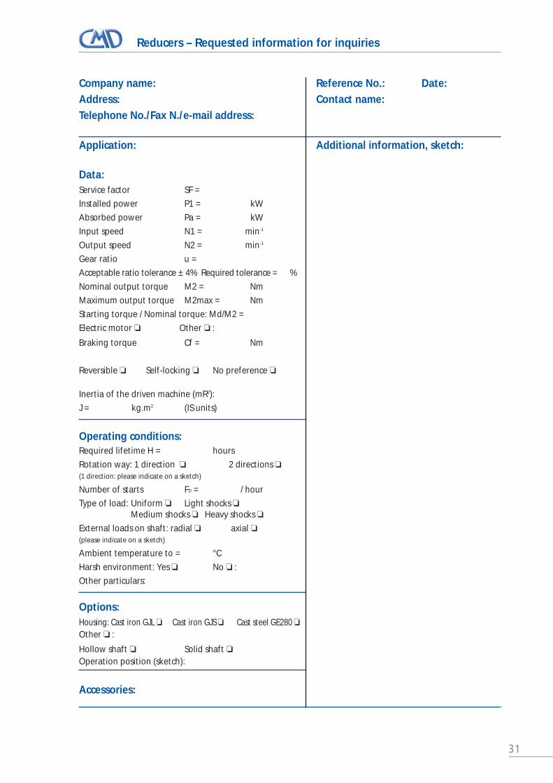
Reducers – Requested information for inquiries
Company name: Reference No.: Date:Address: Contact name:Telephone No./Fax N./e-mail address:
Application: Additional information, sketch:
Data:Service factor SF =
Installed power P1 = kW
Absorbed power Pa = kW
Input speed N1 = min-1
Output speed N2 = min-1
Gear ratio u =
Acceptable ratio tolerance ± 4% Required tolerance = %
Nominal output torque M2 = Nm
Maximum output torque M2max = Nm
Starting torque / Nominal torque: Md/M2 =
Electric motor ❏ Other ❏ :
Braking torque Cf = Nm
Reversible ❏ Self-locking ❏ No preference ❏
Inertia of the driven machine (mR2):
J = kg.m2 (IS units)
Operating conditions:Required lifetime H = hours
Rotation way: 1 direction ❏ 2 directions ❏(1 direction: please indicate on a sketch)
Number of starts FD = / hour
Type of load: Uniform ❏ Light shocks ❏Medium shocks ❏ Heavy shocks ❏
External loads on shaft: radial ❏ axial ❏(please indicate on a sketch)
Ambient temperature to = °C
Harsh environment: Yes ❏ No ❏ :
Other particulars:
Options:Housing: Cast iron GJL ❏ Cast iron GJS ❏ Cast steel GE280 ❏Other ❏ :
Hollow shaft ❏ Solid shaft ❏Operation position (sketch):
Accessories:

32

Worm Gear Sets
For more than 60 years, CMD Durand has been known as the specialist of worm gears. CMD Durand designs andsupplies a wide range of worm gears of high quality for numerous applications in the mechanical as well as theprecision industries. The worm shafts and the worm wheels are designed according to CMD standard withinaccuracy class required.
The technology and dimensions of the gears arethose of CMD Durand standard reducers. CMDDurand may as well offer specific gears in accor-dance with client specific construction (centre dis-tances, gear ratios, gearing backlash and precision).
The required accuracy level is guaranteed by themanufacturing process, based on CNC machines andinternal quality control system.
RoboticOrientation,Welding robot,Handling robot, …
Rubber industryPresses, mixers, extruders
Steel industryMill roller adjustment drives,shearing machine drives, bending machines, wire mills,drawing machines
Army industryGun tank turret drive, vehicle wheel drives
Film industryFilm extruders
TransportationAxle drives, traction drives,
cabin liff
Material handlingWinches, elevators,
slewing drives, lifts, screw jacks
EnergyCoal pulverizing vertical mills
for power plantsSpeed increasers for
hydro-electric turbines
NavyPropeller drive, automatic steering drive
Astronomy - Space industryAntenna drives, satellite tracker,
positioning drives, precision metrology table
Machine toolsTable driveSpindle drivePositioning tableRight angleMill head driveAxis drive
33
34
Worm Gear Sets
CMD standard and dimensions• Standard range of centre distance:
50, 63, 80, 100, 125, 200, 250, 280, 315, 355, 400,450, 500, 560, 630, 710, 800, 900, 1000, 1120, 1250
• Standard ratios: 5, 7.5, 10, 12.5, 15, 20, 25, 30, 40, 50, 60
• Gearing accuracy class in accordance with DIN 3974, ISO 1328:Grade: 7 (general machinery)Grade: 3 4 5 6 (accurate machinery)
• Axial module: 1 to 36 mm
• Worm shaft made of alloyed steel, thread beingheat treated (induction, case carburised ornitriding), the threads are finished onKlingelnberg or Durand grinding machines.
• The worm wheel is made out of dye cast (GK, GM) or centrifugal (GZ) nickel bronze, in order to get the highest possible mechanicalproperties and durability.
Thanks to its own design software, CMD can workout specific gear designs, of any size, in accordanceto customer’s requirements.
The contact pattern of the worm gear teeth is simu-lated on a computer, in accordance with the CMDstandards. A specific contact pattern, in location andarea, can be achieved in order to respond to specificdemands.
The gear cutting process used on CNC Pfauter orDurand machines allows to achieve the best contactpattern for oil film formation as well as optimaladaptation of the working teeth flanks under load,which is effective from the first hours.
Durand worm gears are controlled in accordance toQA standards, guaranteeing the required accuracyclass.
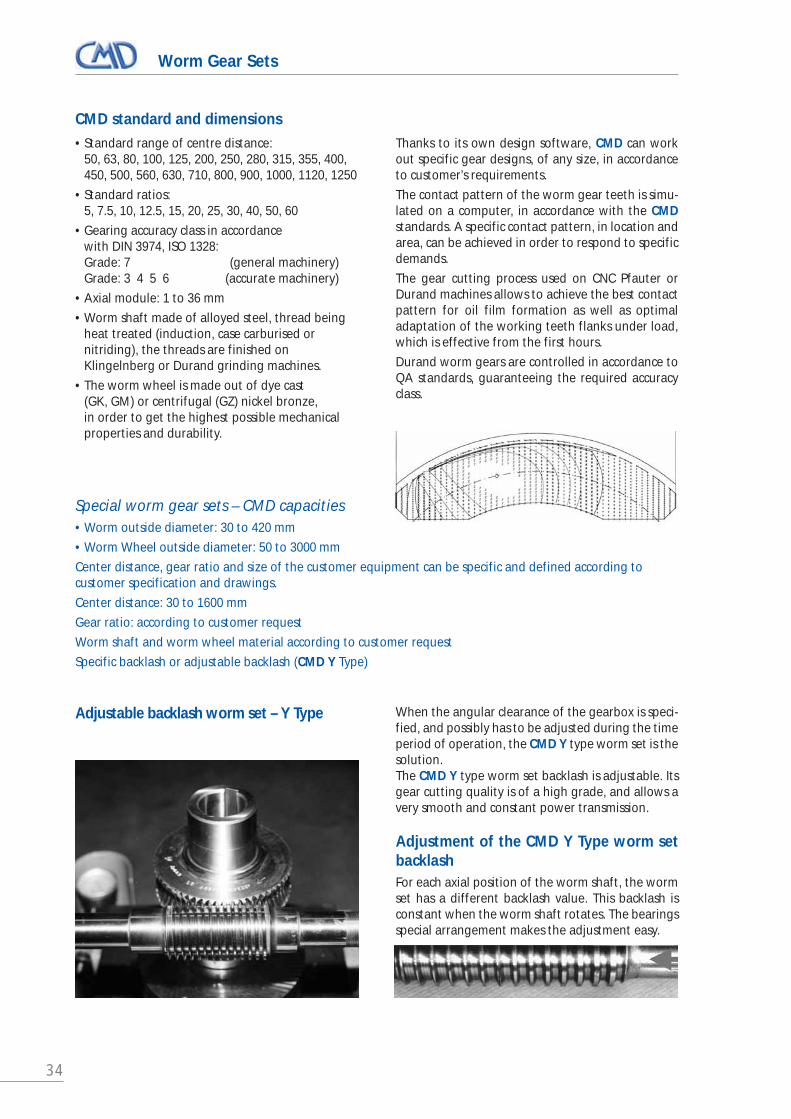
Adjustable backlash worm set – Y Type When the angular clearance of the gearbox is speci-fied, and possibly has to be adjusted during the timeperiod of operation, the CMD Y type worm set is thesolution.The CMD Y type worm set backlash is adjustable. Itsgear cutting quality is of a high grade, and allows avery smooth and constant power transmission.
Adjustment of the CMD Y Type worm setbacklashFor each axial position of the worm shaft, the wormset has a different backlash value. This backlash isconstant when the worm shaft rotates. The bearingsspecial arrangement makes the adjustment easy.
Special worm gear sets – CMD capacities• Worm outside diameter: 30 to 420 mm
• Worm Wheel outside diameter: 50 to 3000 mm
Center distance, gear ratio and size of the customer equipment can be specific and defined according tocustomer specification and drawings.
Center distance: 30 to 1600 mm
Gear ratio: according to customer request
Worm shaft and worm wheel material according to customer request
Specific backlash or adjustable backlash (CMD Y Type)

35
Worm Gear Sets
Power transmission under high vibration conditionsCoal millsNearly 600 CMD large worm gear sets are currently in operation on vertical coal mills manufactured by BHEL,ANSALDO and ALSTOM. These mills are used in power plantsand mills. The CMD worm sets drive the table onto which therollers or balls are milling the material.
Application examples
Technical specifications:
• A wide range of center distance 27" to 54" (686 to 1372 mm)
• Ratio from 10/1 to 20/1
• Transmitted power from 300kW @ 1000rpm to 600kW @ 600rpm
• Design life = 100 000 hours, based on continuous 24h/24 running
• Accuracy class DIN 7
• Worm is made of alloy forging steel, case carburised and ground
• High tensile centrifugal bronze casting is used for the worm
Power transmission in a distorted structureVOITH has selected CMD to supply large worm sets driving its marinepropellers. This choice was made because of the severe runningconditions under which a very high precision level must be achieved:
1- very low noise level, demanding gear accuracy class DIN 5 for the shaftand DIN 6 for the wheel (OD 1625 mm).
2- The contact pattern of the worm set (its position and area), tested inCMD manufacturing plant without load, was first defined andsimulated according to the optimised final contact pattern requiredunder the nominal application load.
In order to simulate the evolution of the contact pattern according tothe load, CMD had to take into account the displacement of the wheelvs the shaft. This displacement is due to the forces acting onto thevertical blades during the vessel propelling, and to the vessel structuredeformation.
Technical characteristics:
• Center distance from 670 to 900 mm
• Reduction ratio from 9 to 14
• Transmitted power from 500kW @ 1200 rpm to 900 kW @ 810 rpm
• Gear teeth accuracy class DIN 5 for the worm shaft, DIN 6 for the wheel
• Worm shaft is made of alloy forging steel, case carburised andground: outside diameter from 200 to 300 mm
• High tensile centrifugal bronze casting is used for the worm wheelswhich can have an outside diameter from 1220 to 1625 mm
Voith photo

36
Worm Gear Sets
The French company Allibert mounts handling robots on its plasticobjects moulding dyes. These robots are used to extract the piecesfrom the dye, and position them for various operations (finishing,control, packing…). These robots use CMD JR type worm sets.
The CMD JR type worm set is designed with a reduced teeth back-lash. It drives the main rotation shaft of the robot with an inchingmotor. The worm shaft is connected to an incoder, controlling theshaft position.
Albora photo
Fast moving positioning – Handling robots
Precision positioning – radar antenna drivesThe French radio astronomy center of Nancay (France) – worldfame for astronomy research – uses many antennæ for sun obser-vation. A very high kinematic precision is requested for theseantennas drives.
The antennæ rotation drives use CMD Durand 0 backlash wormsets. They are mounted into CMD specifically designed housings.
Technical data:
• Center distance 125 mm
• Reduction ratio 60/1
• Continuous running 24h/24, 1 rotation per day
Another application – Drive systems for satellitetrackers2 worm gear screw packs monitor the orientation and theelevation of the trackers.
Technical data:
Elevation worm gear screw pack• Reduction ratio 280/1, power 1.1 / 4.9 kW at 655 / 2670 rpm
• Stroke 2 790 mm, speed 110/440 mm/min
• Dynamic load 220 kN, static load 480 kN
Orientation worm gear screw pack: • Reduction ratio 600/1, power 0.37 kW at 1500 rpm
• Stroke 1 300 mm, speed 24 mm/min
• Dynamic load 200 kN, static load 270 kN
➊
➋
Technical characteristics:
• Center distance 100 to 160 mm
• Reduction ratio from 60/1 to 100/1
• Gear backlash 0.036 to 0.058 mm
• Kinematic angle tolerance of the drive shaft: 1.5 to 2 minutes
• Number of cycles: 200 to 600 per hour

37
Worm Gear Sets
CMD Durand designs and manufactures Y type highquality worms set with backlash adjustment for severalCNC machines makers (Mazak, Mitsubishi, Huron-Graffenstaden…).
The worm set drives the supporting table. A greatkinematic consistency as well as angular position accu-racy are demanded.
Mechanical data:
• Center distance 200 to 665 mm
• Reduction ratio 120 to 180/1
• Accuracy class DIN 4
The CNES (French Space Engineering Centre) has awarded toCMD Durand the design and manufacture of CNC dividingtables of a very high precision grade.
The worm set is driving the rotation of a gauging device usedfor the official approval of a CNES spectrometer.
Kinematic precisionDividing table
Technical data:
• Center distance 395 mm • Reduction ratio 120/1- Adjustable backlash Y type worm set • Accuracy class ISO 2 • Rotation speed : 0.2 rpm • Rotation angle +/- 180°
Accuracy: requested obtainedVerticality: ± 1” < ± 1”Angle: ± 1” < ± 1/3”, equivalent to 0.0001°,
represents less than 1.75 mm on 1 km distance
Kinematic consistency – Machine tolls table drive

38
Worm gear sets – Requested information for inquiries
• Required theoretical center distance aw = mm ou aw = inch
• Housing center distance if known: No ❏ Yes ❏ : nominal value = mm Tolérance : mm
• Gear ratio u =
• Thread helix direction: right ❏ (standard) left ❏
• Accuracy class: standard class 7 ❏ other class: 6 ❏ 5 ❏ 4 ❏ 3 ❏
• Accuracy standard: DIN 3974 ❏ other ❏ :
• Operating as a REDUCER (the worm drives the wheel): Yes ❏ No ❏
• Operating as an INCREASER (the wheel drives the worm): Yes ❏ No ❏
• Operating as a REDUCER and an INCREASER: Yes ❏ No ❏
• Rotation direction of the wheel direction (1) ❏ direction (2) ❏ direction (1) and (2) ❏(Refer to sketch above)
• Gear teeth backlash: CMD standard ❏ required backlash minimum = mm maximum = mm
• Attached drawings or references:
• Y type adjustable backlash gear set: (backlash setting obtained by axial movement of the worm in its bearings)No ❏Yes ❏ : Please mention input and output shafts on the above sketch.
• Attached drawings or references:
Please indicate on the above sketch the required dimensions and rotation direction.
(1) (2) par rapport à l'Observateur
Cocher les cases concernées ❏�
Company name: Reference: Date:Address:Telephone / fax / e-mail: Name:
➔
wheel
wheelright sidehelix
right sidehelix
left sidehelix
left sidehelix
Wormshaft
Wormshaft

39
Main machine tools
MAZAK INTEGREX 30 Lathe
Hobbing PFAUTER P1000 Bronze wheels
Hob grinding machine KLINGELNBERG SNC 50
OKUMA MA 50HB-E Machining center
Worm grinding machine KLINGELNBERG HNC35S

40

41

42
Special worm gear setsWorm gears for Raymond coal pulverizers
Complete range of worm gear sets:- Worm shaft is made of forging steel, case
carburised and finish ground
- Worm wheel is made of high speed centri-fugal bronze for sizes:
27’’ centre distance = 686 mm
36’’ centre distance = 914 mm
41’’ centre distance = 1041 mm
48’’ centre distance = 1219 mm
54’’ centre distance = 1371 mm
Gear ratios: 54/5 – 65/4 – 76/5 – 94/5 104/5 – 94/7 and 100/7
Our capacity is limited to 1600 mm centre distance.
Almost 600 CMD Durand worm gear setswere delivered for Raymond coal pulveri-zers to the main world manufacturers.These gears are used in power plants andmills. The milling of the raw material isobtained with suspended rollers, pressedonto the rotating table, which is driven bythe CMD Durand worm gear set.

43
Gearbox for printing machine
Dual output shaft worm gearbox,multi purpose drive
- Each gearbox has a center distance =200 mm with a reduction ratio i = 4 and isdriving 2 cylinders simultaneously. Thecombination of several gearboxes on theprinting machine allows high quality oftwo-colour and four-colour printing.
- Technical specification: 80kW, output speed500 rpm, continuous 24h/24 running.
- Each shaft’s angular position is fixedagainst the other’s, thanks to an internalclutch system which can be actuated ins-tantly. A second clutch system allows the‘’inching’’ running, in order to mount theprinting plates onto the cylinders.
- The worm shaft can move axially inside itshousing, allowing a compensation of thepaper expansion when it is wet. The print-ing accuracy obtained is +/- 0.03 mm.
- Several sensors integrated in the equip-ment make sure the system is runningsafely.

44
Clarifiers – Complete drives
Gear motor, with a vertical outputshaft, with guaranteed sealingobtained by internal slinger.
Torque range from 20 000 Nm to1 000 000 Nm and more.
Very high reduction ratio : I = 10 000/1,…30 000/1, …etc.
Output speed ≤ 0.1 rpm
The spline shaft of the clarifier slides intothe low speed shaft of the gearbox,enabling the adjustment of the drag scra-per’s position vs the bottom of the tank. Thisposition is determined by the action of a lift-ing jack that is able to lift up to 100 tons andmore. The position of the jack is monitoredby limit switches (mechanical and electrical),and is visually displayed on the gearbox.

45
Sugar Industry – Mixers drive Vertical or horizontal
Range of geared motors, with 2 or 3 stages of worm gear reduction:
- Cast iron housing
- Continuous (24h/24) running
- Running 3 months per year
- Low Speed shaft torque from 20 000 to120 000 Nm, speed of 1 rpm
- Torque from 80 000 to 600 000 Nm, speedof 0.4 rpm for the largest gearboxes.
The electrical motor is fixed on the primarystage gearbox. The whole gearbox is float-ing on the mixer’s shaft.
The secondary gearbox’s torque is compen-sated by the torque reaction arm, and shockabsorber, which is equipped with:
- either 1 or 2 safety sensors
- or 1 electronic sensor allowing:
- permanent display of the transmittedtorque
- peak torques memorizing
- electrical outputs for online monitoring
The simplicity and robustness of the CMDDurand worm gearbox guarantee its reliabi-lity for this application.

46
Barring – Inching drive Auxiliary slow speed drive
The main functions can be:- Start a high inertia machine
(Ex: large fan)
- Start and drive at low speed
(Ex: vessel drive shaft, high capacity dieselengines…)
- Start, drive at low speed, position
(Ex: Mills, kilns, conveyors…)
- Start, drive, slow down, stop
(Ex: gas turbine)
Options:- hydraulic coupling for high inertia start.
- One way clutch, gear clutch…
- Telescopic gear coupling, cardan shaft,etc… for compensating the thermal expan-sion of the driven shaft.
- Braking system.

47
Steel industry - Steel mill screw jacks worm gearboxes
The center distance between the2 cylinders of a steel mill isadjusted by a screw jack system,driven by the worm wheel of aworm gearbox. The equipmentof a mill can be:- 2 screw jacks worm gearboxes for the
adjustment of the horizontal mill.
- 4 screw jacks worm gearboxes for theadjustment of the vertical mill.
The screw jack worm gearboxesinclude the following components:- Steel housing.
- Low speed hub made of steel or GJS castiron with a large bore and 6 or 8 wideparallel splines.
- Oil injection lubrication.
- The splines are lubricated against slidingheating.
2 opposite gearboxes on the same mill dri-ven by the same motor secure the synchroni-zation. They are connected with a clutch in order to allow parallelism setting.
Housing has to be strong enough in order tocope with:
- The high torque transmitted when un-locking.
- The high axial forces transmitted by thescrew when setting under load.
586FSP reducer
Manesmann Demag doc.

48
Processing industry
Shearing machine
The JUMBOFLEX worm gearbox, size 900, drives the crankshaft/rodsystem of the 600 tons PINCHARTDENY shearing machine.
Technical data:- Centre distance 900 mm
- Reduction ratio 66
- Dynamic output torque 424 080 Nm at10 rpm
- Maximum peak torque 1 291 630 Nm
- The oil injection system insures lubricationof the gears and bearings with syntheticoil.
Bull block driving
The “Bull block” worm gearboxes areused to draw the copper and steeltubes to the required dimensions.
The tubes are wound up around a coilmounted on the gearbox low speed shaft.The tube drawing force is obtained by thegearbox output torque, and can reach up to17 tons for steel tubes.
Technical characteristics:
- Centre distance 610, 630, 800 mm
- Reduction ratio 9 to 17
- Variable output speed from 0 to 525 rpm
- Continuous running 24h/24
- Maximum output torque 129 200 Nm at29.3 rpm (steel tubes)
The running conditions are extremelysevere: the starting load can be very high,and requires a specifically adapted contactpattern in order to have a sufficient oil filmat start.

49
Jumboflex worm gearbox drive(sizes from 560 to 1250)
2 JUMBOFLEX gearboxes drive thecrankshaft/rod system of each automotivepress, used by German car manufacturers.
Worm gearbox technical data: - JUMBOFLEX worm gearbox, size 900,
weight 7300 kg
- Reduction ratio = 20
- Nominal Output torque 190 000 Nm at15 rpm
- Maximum output torque 570 000 Nm
- Continuous (24h/24) running. Requiredservice life = 80 000 hours.
- Reduced backlash is required, as well astorsional rigidity of the shafts.
A primary gearbox insures a primary reduc-tion ratio, and speed synchronization bet-ween the 2 gearboxes.
The worm gear solution was chosen becauseof its specific advantages:
- A compact right angle function with areduction ratio of 20.
- A very high torsional rigidity of the inputand output shafts.
- Smoothness of gearing.
ERFURT doc.
JUMBOFLEX reducer
Automotive press drive
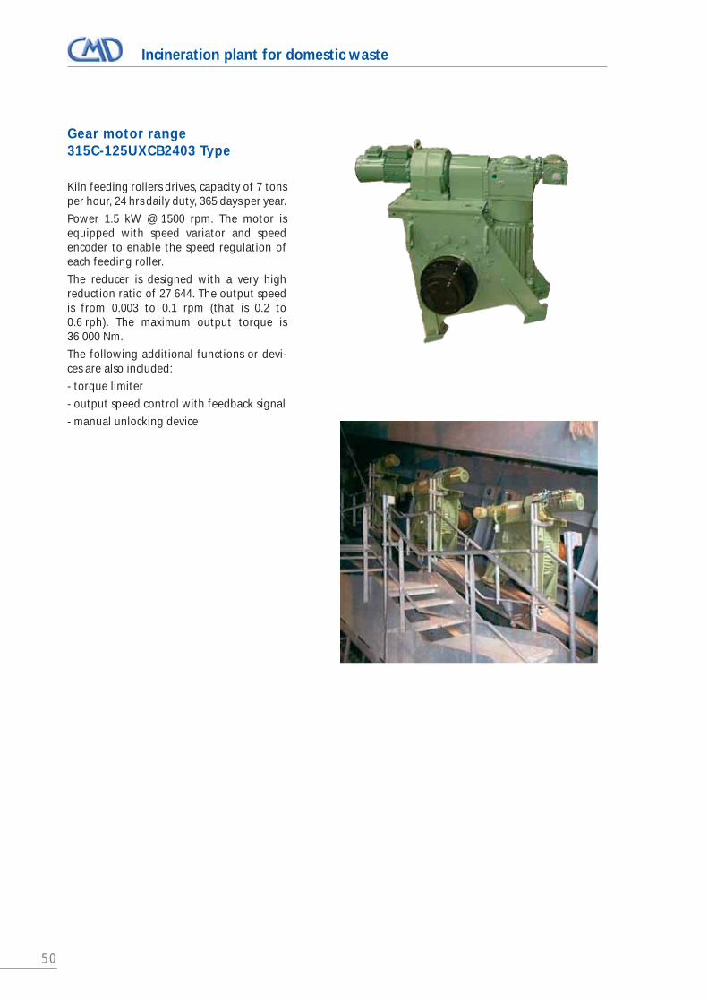
50
Incineration plant for domestic waste
Gear motor range 315C-125UXCB2403 Type
Kiln feeding rollers drives, capacity of 7 tonsper hour, 24 hrs daily duty, 365 days per year.
Power 1.5 kW @ 1500 rpm. The motor isequipped with speed variator and speedencoder to enable the speed regulation ofeach feeding roller.
The reducer is designed with a very highreduction ratio of 27 644. The output speedis from 0.003 to 0.1 rpm (that is 0.2 to0.6 rph). The maximum output torque is36 000 Nm.
The following additional functions or devi-ces are also included:
- torque limiter
- output speed control with feedback signal
- manual unlocking device

51
Water level control - Dam gate drive
Steel case gear motors with highreduction ratios (7 000/1 to 12 000/1)
Lifting load on chain up to 70/80 tons. Lift-ing speed 0.2 m/min.
The gear motors are supplied fully equippedwith chain wheel and chain. The chain isdesigned with a security factor of 5 onnominal load.
Accessories supplied:
- brake motor with manual release
- permanent electronic control of the loadon the chain, including:
- permanent load display
- four output relays (max load, min load...)
- 4-20 mA outputs for plc control
- chain limit switches
- control of gate angle
- standby set, comprising portable gearmotor and electrical generator
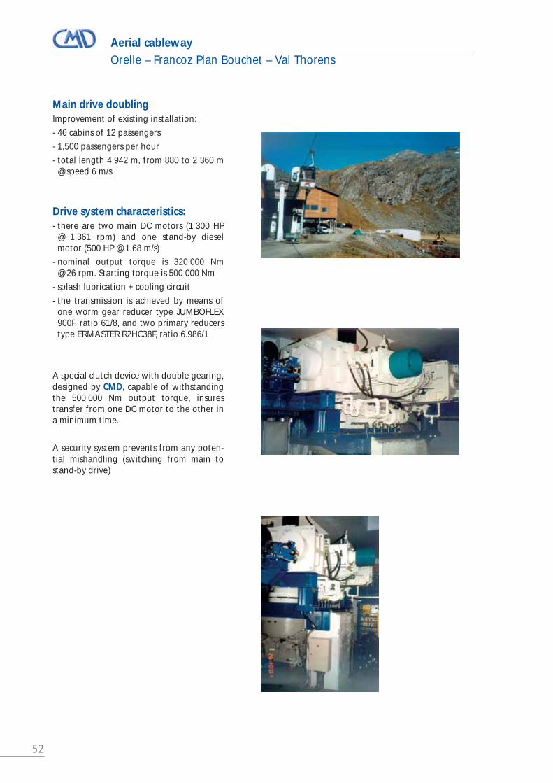
52
Aerial cablewayOrelle – Francoz Plan Bouchet – Val Thorens
Main drive doublingImprovement of existing installation:
- 46 cabins of 12 passengers
- 1,500 passengers per hour
- total length 4 942 m, from 880 to 2 360 m @ speed 6 m/s.
Drive system characteristics:- there are two main DC motors (1 300 HP
@ 1 361 rpm) and one stand-by dieselmotor (500 HP @ 1.68 m/s)
- nominal output torque is 320 000 Nm@ 26 rpm. Starting torque is 500 000 Nm
- splash lubrication + cooling circuit
- the transmission is achieved by means ofone worm gear reducer type JUMBOFLEX900F, ratio 61/8, and two primary reducerstype ERMASTER R2HC38F, ratio 6.986/1
A special clutch device with double gearing,designed by CMD, capable of withstandingthe 500 000 Nm output torque, insurestransfer from one DC motor to the other ina minimum time.
A security system prevents from any poten-tial mishandling (switching from main tostand-by drive)

Janu
ary
20
20
SALES OFFICE36, Avenue de l’EuropeImmeuble de l’Etendard BP4378142 VELIZY-VILLACOUBLAYFRANCE
+33 (0)1 34 63 12 24
FOURCHAMBAULT PLANT33, rue du 4 Septembre
58600 FOURCHAMBAULTFRANCE
French design & manufacture


