Page 1
RFS-CT-2006-00031 - HISTWIN
High-Strength Steel Tower for Wind Turbine
WP3.1 – EVALUATION OF SHELL THICKNESSES
BACKGROUND DOCUMENT
Contractors AUTH, FCTUC
Authors C. Baniotopoulos, I. Lavasas, G. Nikolaides, P. Zervas
Last modified 13/04/2009
Reviewed by Date dd/mm/yyyy
Page 2
C. Baniotopoulos, I. Lavasas HISTWIN 13/05/2008
WP3.1, Background document
TABLE OF CONTENTS
1. WORK PACKAGE DESCRIPTION....................................................................... 1
2. BACKGROUND DOCUMENT ............................................................................... 2
2.1. GENERAL .......................................................................................................................... 2
2.2. ANCHORING SYSTEM CONFIGURATION ............................................................................ 2
2.3. F.E. STRUCTURAL MODEL................................................................................................. 3
2.4. VERIFICATIONS................................................................................................................. 5
2.5. REFERENCES ..................................................................................................................... 8
Page 3
C. Baniotopoulos, I. Lavasas HISTWIN 13/05/2008
WP3.1, Background document 1/8
1. WORK PACKAGE DESCRIPTION
WP leader: AUTH
Contractors: FCTUC
Task: Review of a current design procedure for preloaded anchors.
Deliverables: Background document
Starts: 01/07/2006
Ends: 30/09/2006
Page 4
C. Baniotopoulos, I. Lavasas HISTWIN 13/05/2008
WP3.1, Background document 2/8
2. BACKGROUND DOCUMENT
2.1. General
Anchoring of the wind turbine steel tower to the R.C. pedestal by means of preloaded
anchors is one of the two most commonly configurations used, the other being the em-
bedment of the lowest course of the shell to the foundation.
Although no special benefit is gained concerning the plastic limit state (LS1), preload-
ing to the anchors is mandatory for the fatigue limit state (LS4), the safety requirements
of which otherwise are not met by conventional anchoring. Anchors are partially pre-
stressed, at a level of about 50%, which is a good compromise, satisfying the verifications
of the anchors against fatigue in one hand and keeping the R.C. foundation local strain
within the acceptable margins, on the other.
Preloaded anchors are not explicitly covered by the Eurocodes. The combination though
of the relevant Standards, such as: [EC 3-1-8], [EC 3-1-9], [EC 2-1-1], [ETAG 001] etc.
can provide an acceptable degree of computational competence. It is worth mentioning
in more detail the specific clauses of [EC 3-1-8] determining the design of the anchoring
components for the plastic limit state, which are:
• §2 : Basis of design
• §3.1 : Connections made with bolts, rivets or pins – Bolts, nuts and washers
• §3.3 : Connections made with bolts, rivets or pins – Anchor bolts
• §3.4 : Connections made with bolts, rivets or pins – Categories of bolted connections
• §3.5 : Connections made with bolts, rivets or pins – Positioning of holes for bolts
and rivets
• §3.6 : Connections made with bolts, rivets or pins – Design resistance of individ-
ual fasteners
• §3.9 : Connections made with bolts, rivets or pins – Slip-resistant connections us-
ing 8.8 or 10.9 bolts
• §6.2.2 : Structural joints – Design Resistance – Shear forces
• §6.2.5 : Structural joints – Design Resistance – Equivalent T-stub in compression
• §6.2.6 : Structural joints – Design Resistance – Design Resistance of basic compo-
nents – (§6.2.6.9 ÷ §6.2.6.12)
• §6.2.8 : Structural joints – Design Resistance – Design resistance of column bases
with base plates
2.2. Anchoring system configuration
The anchoring system consists of the set of partially presressed anchors at a circumfer-
ential arrangement, connecting the base plate of the tower to the circular washer plate
Page 5
C. Baniotopoulos, I. Lavasas HISTWIN 13/05/2008
WP3.1, Background document 3/8
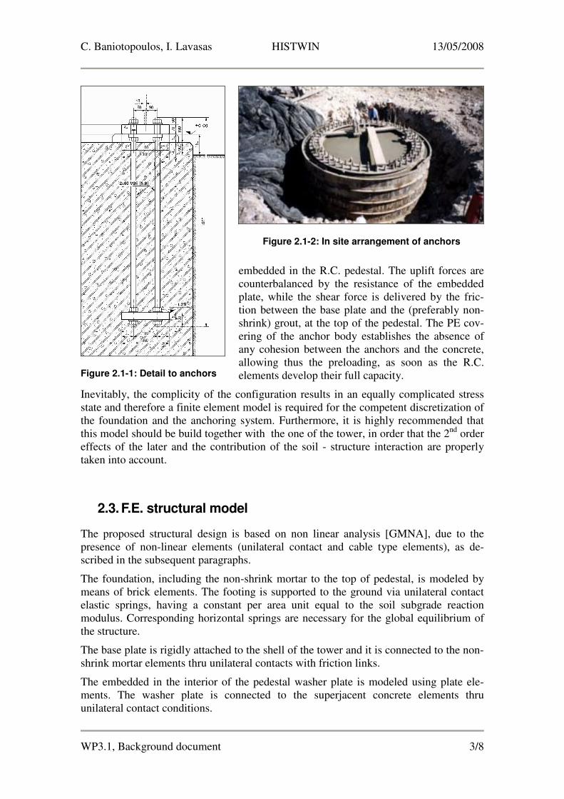
embedded in the R.C. pedestal. The uplift forces are
counterbalanced by the resistance of the embedded
plate, while the shear force is delivered by the fric-
tion between the base plate and the (preferably non-
shrink) grout, at the top of the pedestal. The PE cov-
ering of the anchor body establishes the absence of
any cohesion between the anchors and the concrete,
allowing thus the preloading, as soon as the R.C.
elements develop their full capacity.
Inevitably, the complicity of the configuration results in an equally complicated stress
state and therefore a finite element model is required for the competent discretization of
the foundation and the anchoring system. Furthermore, it is highly recommended that
this model should be build together with the one of the tower, in order that the 2nd
order
effects of the later and the contribution of the soil - structure interaction are properly
taken into account.
2.3. F.E. structural model
The proposed structural design is based on non linear analysis [GMNA], due to the
presence of non-linear elements (unilateral contact and cable type elements), as de-
scribed in the subsequent paragraphs.
The foundation, including the non-shrink mortar to the top of pedestal, is modeled by
means of brick elements. The footing is supported to the ground via unilateral contact
elastic springs, having a constant per area unit equal to the soil subgrade reaction
modulus. Corresponding horizontal springs are necessary for the global equilibrium of
the structure.
The base plate is rigidly attached to the shell of the tower and it is connected to the non-
shrink mortar elements thru unilateral contacts with friction links.
The embedded in the interior of the pedestal washer plate is modeled using plate ele-
ments. The washer plate is connected to the superjacent concrete elements thru
unilateral contact conditions.
Figure 2.1-1: Detail to anchors
Figure 2.1-2: In site arrangement of anchors
Page 6
C. Baniotopoulos, I. Lavasas HISTWIN 13/05/2008
WP3.1, Background document 4/8
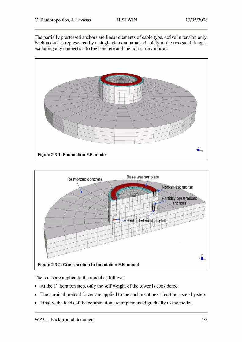
The partially prestessed anchors are linear elements of cable type, active in tension only.
Each anchor is represented by a single element, attached solely to the two steel flanges,
excluding any connection to the concrete and the non-shrink mortar.
The loads are applied to the model as follows:
• At the 1st iteration step, only the self weight of the tower is considered.
• The nominal preload forces are applied to the anchors at next iterations, step by step.
• Finally, the loads of the combination are implemented gradually to the model.
Figure 2.3-2: Cross section to foundation F.E. model
Figure 2.3-1: Foundation F.E. model
Page 7
C. Baniotopoulos, I. Lavasas HISTWIN 13/05/2008
WP3.1, Background document 5/8
It is noted though that the procedure presented above can not be performed to the seis-
mic combinations, since spectral response analysis is incompatible with non-linearities.
Therefore, all unilateral contact links have to be replaced with rigid ones, preventing in
this way the investigation of the anchor forces. A proposal to overcome this problem is
demonstrated as follows:
• Solve the spectral response case, the tower the rigidly connected to the foundation.
• Determine the forces acting on the pedestal, using the SRSS combination.
• Construct a new model of the foundation only, incorporating all non-linearities.
• Apply the reactions of the tower to the foundation model as static loading and exe-
cute the iterative analysis
As an alternative, in the rare case of the earthquake being crucial for the design of the
tower, the additional representation of the seismic action in terms of acceleration time-
histories may be adopted and the spectral response can be carried out.
Regarding the direct estimation of the anchor forces by hand calculation, such a task is
practically not feasible, since the position of the neutral line of the anchoring system can
be determined only with the introduction of the elasticity conditions, which requires an
iterative calculation procedure. A less accurate assesment of the anchor forces can be
achieved with the aid of a simpler Finite Element model, including only the bottom
flanges (with unilateral elastic support) and the anchors (see Figure [F-2.3-3]).
2.4. Verifications
The design of the foundation – anchoring system covers the verification of the follow-
ing components (see Figure [F-2.4-1]):
Figure 2.3-3: Alternative F.E. model for the estimation of anchor forces
Page 8
C. Baniotopoulos, I. Lavasas HISTWIN 13/05/2008
WP3.1, Background document 6/8
• Washer and base plates (Von Misses stresses)
• Prestressed anchors (tensile forces)
• Non-shrink mortar (compressive and shear stresses)
• Concrete (compressive, shear and punching shear stresses)
• Reinforcement bars
• Rigid body equilibrium for the structure.
The required reinforcement is calculated by the integration of the tensile stresses of the
brick elements at the check points as marked in Figure [F-2.4-2]:
• [1], [2] : Footing, bottom mesh
• [3], [4] : Footing, top mesh
Figure 2.4-2: Check points
Figure 2.4-1: Stress diagram
Page 9
C. Baniotopoulos, I. Lavasas HISTWIN 13/05/2008
WP3.1, Background document 7/8
• [5] : Top of the pedestal mesh
• [6] : Pedestal vertical rebar, for the transfer of the tensile anchor forces
• [7] : Circumferential reinforcement, controlling the split-up forces due to the an-
chor preloading stress due to Poisson ratio.
.
Page 10
C. Baniotopoulos, I. Lavasas HISTWIN 13/05/2008
WP3.1, Background document 8/8
2.5. References
[1] EC 2-1-1: Design of concrete structures – General rules and rules for buildings, 2004
[2] EN 1993-1-1: Design of steel structures – General rules and rules for buildings, 2005
[3] EN 1993-3-1: 2006: Design of steel structures – Towers, masts and chimneys –
Towers and masts, 2006
[4] EC 3-1-8: Design of steel structures – Design of joints, 2005
[5] EC 3-1-9: Design of steel structures – Fatigue, 2005
[6] EN 1998-1: Design of structures for earthquake resistance – General rules, seis-
mic actions and rules for buildings, 2004
[7] EN 1998-6: Design of structures for earthquake resistance – Towers, masts and
chimneys, 2005
[8] ETAG 001: Metal anchors for use in concrete, 1997
[9] GL Wind 2003 IV – Part1: Guideline for the Certification of Wind Turbines, 2004
[10] ACI 349-01: Code Requirements for Nuclear Related Concrete Structures – Ap-
pendix B: Anchoring to Concrete, 2001