16
WP92031 Electric walkie scale (WP9202 display with well cells) User’s Manual Rev 1
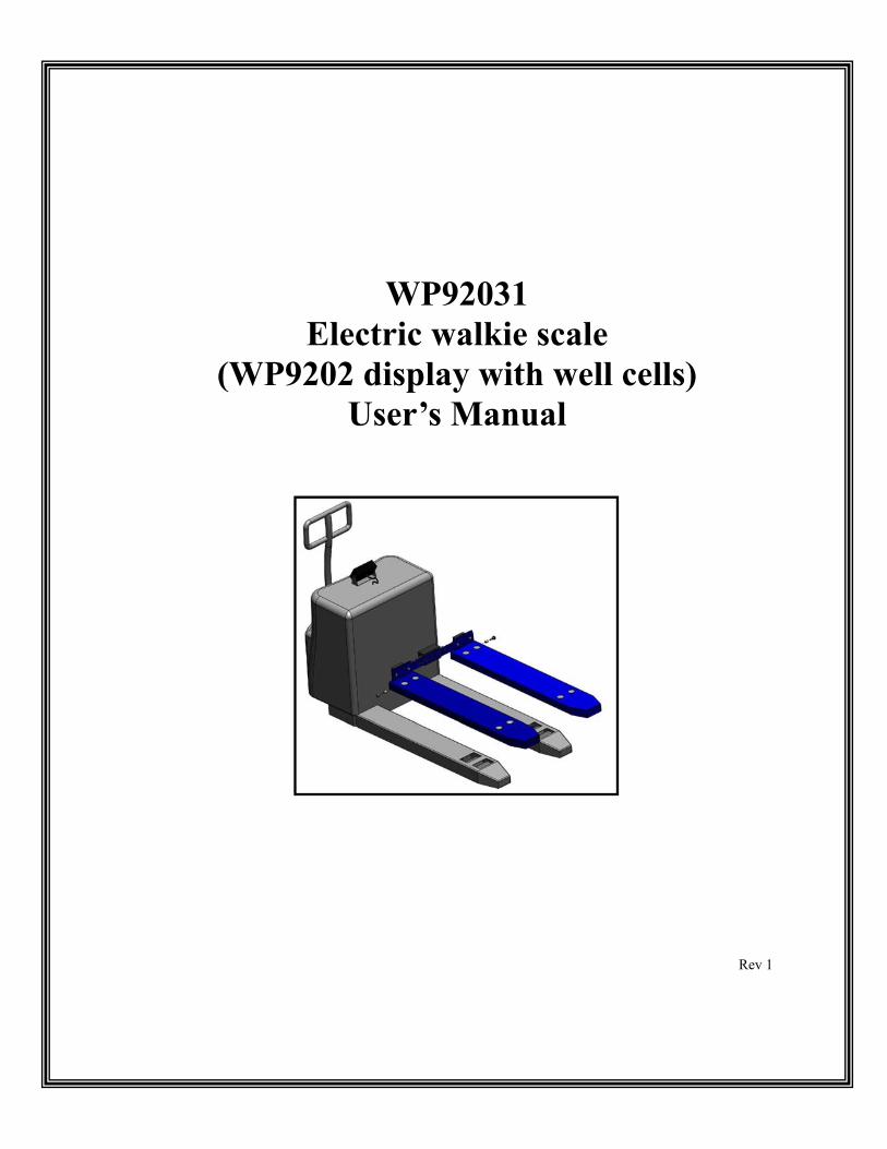
WP92031 Electric walkie scale
(WP9202 display with well cells) User’s Manual
Rev 1

2
Table of contents
Loadcell location and specifications 3
Installation guide 4, 5
Calibration 5, 6
Safety procedures 7
Maintenance 7
Specifications 8
WP9202 manual 9-14

3
Pair
Pair
Pair
Pair
(Individual Cells)

Electric Walkie Scale Kit Parts List
QTY Part Number Description
1 AWT05-506078 Weigh Point Service Parts Digital Indicator 12VDC
8 AWT05-506121 Weigh Point Service Parts Disc Load Cell
4
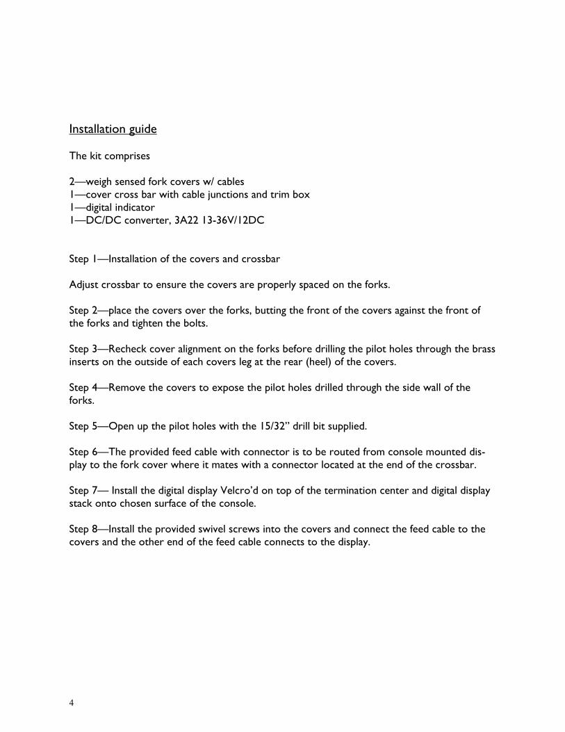
Installation guide The kit comprises 2—weigh sensed fork covers w/ cables 1—cover cross bar with cable junctions and trim box 1—digital indicator 1—DC/DC converter, 3A22 13-36V/12DC Step 1—Installation of the covers and crossbar Adjust crossbar to ensure the covers are properly spaced on the forks. Step 2—place the covers over the forks, butting the front of the covers against the front of the forks and tighten the bolts. Step 3—Recheck cover alignment on the forks before drilling the pilot holes through the brass inserts on the outside of each covers leg at the rear (heel) of the covers. Step 4—Remove the covers to expose the pilot holes drilled through the side wall of the forks. Step 5—Open up the pilot holes with the 15/32” drill bit supplied. Step 6—The provided feed cable with connector is to be routed from console mounted dis-play to the fork cover where it mates with a connector located at the end of the crossbar. Step 7— Install the digital display Velcro’d on top of the termination center and digital display stack onto chosen surface of the console. Step 8—Install the provided swivel screws into the covers and connect the feed cable to the covers and the other end of the feed cable connects to the display.
5
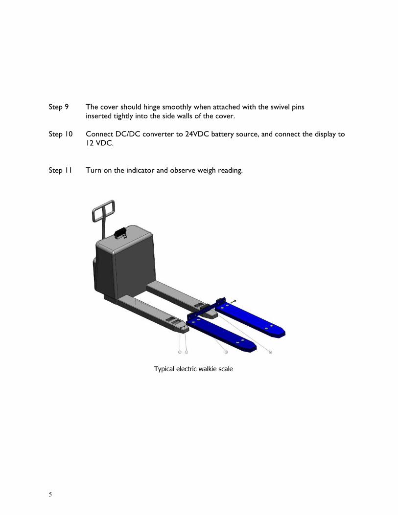
Step 9 The cover should hinge smoothly when attached with the swivel pins inserted tightly into the side walls of the cover. Step 10 Connect DC/DC converter to 24VDC battery source, and connect the display to 12 VDC. Step 11 Turn on the indicator and observe weigh reading.
Typical electric walkie scale

6
Diagnosis—Repair The system is akin to a standard commercial 4-loadcell weigh scale e.g. floor scale, truck scale, etc. Therefore your local scale service company will be able to diagnose and calibrate. The scale company will note the following specifications of the weigh bridge. Typically there are 8 load sensors each 700 ohm impedance. These sensors are paired into the trim boxes 4 calibration points (see diagram for pairing) The WP9202 digital indicator manual is provided for calibration procedures. Calibration weight The most accurate procedure is to select a calibration weight at approximately 2/3 the normal lifting load weights. Weighing on this system requires the load to be placed on a skid or pallet. Do not place the weight directly on the forks. Calibrating weight should be centered on the skid or pallet. Please refer to the WP9202 manual for calibration procedure. Example: A 4500 lb. system will be utilized to capacity, however normal loads will be typically 2300 lbs. Therefore, use weight of 2/3 of 2300 lbs. or 1500 lbs. This is simply a guideline, 1000 to 2000 lb. weights will work too. Warranty – Weigh Point provides free repair or replacement of faulty material and work-manship of the weigh system. Travel and shipping costs excluded. No other warranty is ex-pressed or implied.

7
Safety Procedures • Never overload your electric walkie more than 150% of capacity. Stay within rated
capacity. • Distribute the load evenly on the forks. Do not concentrate loads at one point or
significantly load on one fork more than the other. • Never put your feet, hands or any other body part under the frame assembly. • Do not allow your walkie to drop from one level to another. Even a drop of 1” (25mm)
more than doubles the effective load momentarily and results in a “Shock” which can bend or break components.
• Always ensure load is stable before moving to eliminate opportunity for load shift.
Maintenance Performance of the walkie is generally non deteriorating, however, there are factors that affect accuracy and reliability. There are preventative maintenance procedures that can be performed by skilled technicians to revitalize the system and ensure trouble free operation of your system: On a monthly basis, operators should fully raise the truck and visually inspect the following components: • Front wheels for string, or any other debris caught in front wheel assembly. • Ensure that the fork covers are secure and tighten if required. • Ensure that all dirt and dust is cleaned from the WP9202 display membrane (use only a soft cloth
moistened with a non-abrasive cleaner for this procedure). Contact our sales department for more information about scheduled service checks.
Truck maintenance The scale covers can be removed to lubricate the fittings or simply raise the scale covers (these hinge). There has been no alteration to truck, although the front drive wheels might have the diameter reduced to provide a lower height.

8
Specifications Wiring There’s usually 8 loadcells in each system (4 per fork). Each loadcell has two excitation lines and two signal lines. All similar wires of each loadcell are paralleled. Individual loadcell specifications Input resistance 700—750 Ω Output resistance 700 Ω Temperature range 10°C to 60°C The walkie scale derives the power from the truck’s battery pack

9
Manual 9202 _________________________________________________________ Introduction Best results are achieved by following these simple steps: 1. calibrate and weigh loads centered on the forks, always utilize a pallet for
these procedures. 2. Calibrate at the approximate most prevalent weight, e.g. if your usual
weights are between 500 and 1000 lbs. then calibrate with a 750 lb. test weight. This doesn’t prevent reasonable weight readings below or above your usual weights.
3. Keep a weighed object available for periodic weigh checks. 4. Periodically check the hold down bolts to ensure these are secure.
10
1 2 3 4 5
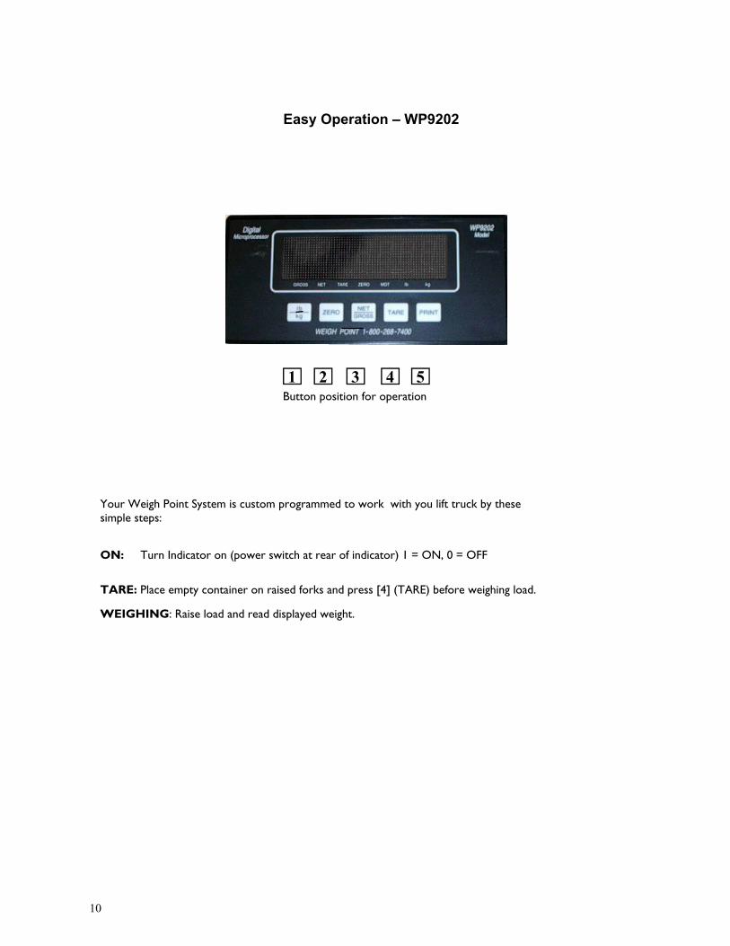
Easy Operation – WP9202
Your Weigh Point System is custom programmed to work with you lift truck by these simple steps:
ON: Turn Indicator on (power switch at rear of indicator) 1 = ON, 0 = OFF TARE: Place empty container on raised forks and press [4] (TARE) before weighing load.
WEIGHING: Raise load and read displayed weight.
Button position for operation

11
The indicator is programmed at factory with appropriate parameter settings. To change parameters see WP92031 parameter sheet (page 12). Your Weigh Point System is custom programmed to work with the pallet truck by these simple steps in the event you wish to recalibrate system. 1) Slide the switch behind the rear inspection plate. (at the back of Display) 2) With key [1] depressed turn indicator on. See F1 displayed. Raise your forks off the ground. Ramp F1 to F15 with [5] to go forward, or [4] to go backwards. 3) With F15 displayed and no weight on forks press key [2] then press key [3] 4) Lift known load and press key [4] or [5] to display F16 5) With F16 displayed press [2]. Proceed with entering known weight using keys [4] (shift) and key [5] ramp numbers. 6) Press [3] to set weight, 7) Move slide Switch at rear of indicator to reset system. Setting designate “A” are listed on page 11. These settings are accessed by powering the display, then slide switch to calibration mode whilst holding button 1 depressed, see A1 displayed (ramp button 4 or 5 to desired “A” position press button 2 to display “A” value. Alter “A” setting by ramping button 4 or 5, set “A” by pressing button 3 Return to weighing by sliding switch to weigh mode position.
One Time Calibration – WP9202
1 2 3 4 5
Button Position for calibrating
12
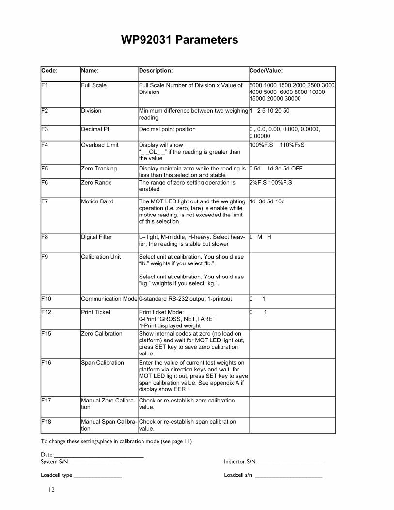
To change these settings,place in calibration mode (see page 11) Date ____________________________ System S/N ________________ Indicator S/N _____________________ Loadcell type _______________ Loadcell s/n _____________________
Code: Name: Description: Code/Value:
F1
Full Scale Full Scale Number of Division x Value of Division
5000 1000 1500 2000 2500 3000 4000 5000 6000 8000 10000 15000 20000 30000
F2 Division Minimum difference between two weighing reading
1 2 5 10 20 50
F3 Decimal Pt. Decimal point position 0 , 0.0, 0.00, 0.000, 0.0000, 0.00000
F4 Overload Limit Display will show “_ _OL_ _” if the reading is greater than the value
100%F.S 110%FsS
F5 Zero Tracking Display maintain zero while the reading is less than this selection and stable
0.5d 1d 3d 5d OFF
F6 Zero Range The range of zero-setting operation is enabled
2%F.S 100%F.S
F7 Motion Band The MOT LED light out and the weighting operation (I.e. zero, tare) is enable while motive reading, is not exceeded the limit of this selection
1d 3d 5d 10d
F8 Digital Filter L– light, M-middle, H-heavy. Select heav-ier, the reading is stable but slower
L M H
F9 Calibration Unit Select unit at calibration. You should use “lb.” weights if you select “lb.”. Select unit at calibration. You should use “kg.” weights if you select “kg.”.
F10 Communication Mode 0-standard RS-232 output 1-printout 0 1
F12 Print Ticket Print ticket Mode: 0-Print “GROSS, NET,TARE” 1-Print displayed weight
0 1
F15 Zero Calibration Show internal codes at zero (no load on platform) and wait for MOT LED light out, press SET key to save zero calibration value.
F16 Span Calibration Enter the value of current test weights on platform via direction keys and wait for MOT LED light out, press SET key to save span calibration value. See appendix A if display show EER 1
F17 Manual Zero Calibra-tion
Check or re-establish zero calibration value.
F18 Manual Span Calibra-tion
Check or re-establish span calibration value.
WP92031 Parameters

13
Code: Name: Description: Code/Value:
A1
Baud Rate Set baud rate of the RS-232 serial com-munication when F10 is 0
2400 4800 9600
A2 Communication Mode “c”=continous mode “d”=command mode
C d
A3 Data Bits and Parity 8N: 8 data bits with no parity bit and 1 stop bit 7O: 7 data bits with odd parity bit and 1 stop bit 7E: 7 data bits with even parity bit and 1 stop bit
8N 7O 7E
A4 Disable the lb/kg Key “0”= Disable the lb/kg key “1”= Enable the lb/kg key
0 1
A5 ID No. Enable “0”= Disable the ID No. “1”= Enable the ID No.
0 1
A6 ID No. Entry Pressing [←] and [→] key to input ID No. and pressing the [SET] key to store and return to A6. Displaying Axxxxx. Prints ID flashing. No. Column after ID No. begin set, (see APPE. ) 6-bit ID No. can be inputted at most when
A7 0 – typical 1 – counting feature 2 – peakhold 3 – accumulation mode 4 – accumulation and peakhold
A8 Set threshold value
Typical settings “A” Scale 1. When the power is ON, press key [1] and hold, then slide the switch behind the rear inspection plate.
The displays shows A1. 2. Ramp A1 to A8 with keys [5] to go forward, or key [4] to go backwards 3. Press key [2], shows value to change value use key [4] or [5] 4. To save/accept displayed data press key [3]
Parameter “A” Scale
Note: Factory values for A7 = 4 accumulation and peakhold A8 = 100 peak detect threshold is 100 lbs.

14
Error Codes
ERROR CODE PROBLEM SOLUTION
Err1 Input signal of the load cell is too low.
Examine whether there are items on the scale.
Err2 EEPROM Error Change EEPROM
Err3 Key-in weight value in calibration mode is larger than full scale capac-ity
Reduce weight value in calibration mode or accrete full-scale capacity.
Err4 Calibration yard is too large Reduce calibration divisions.
Err5 Unit selected is wrong Change F9 or F11
Err6 Decimal position selected is wrong Change decimal position in F3
Err7 The weight of one sample is too light Check a greater sample item until display is 1
_ _OL_ _ Overload Materials too much
===== A/D not working Examine the wire of the load cell, if well, change the print panel.

Warranty One year free replacement of faulty material and/or workmanship of the scale system. Cabling and batteries are not warranted. No other warranty liability is expressed or implied. 90 day warranty on all service parts. Precautionary procedures: To prevent voiding warranty
Weigh scales are measuring devices and require reasonable handling and care
Inspect cabling to ensure no snagging will occur. Note that damaged cables are
not covered by warranty.
Static buildup can easily destroy the microprocessor display. If static build up is suspected then take precautions such as use of grounding straps or chains, anti-marring tires are particularly responsible for static buildup
Periodic inspection and adjustment of the scale components is required for
scale longevity and safety.
Please note the precautionary notes are mandated as a condition of the product
warranty.


