20
WR MATTCO RECIPROCATING PUMP PULSATION CONTROL EQUIPMENT
WR MATTCO RECIPROCATING PUMP
PULSATION CONTROL EQUIPMENT
PAGE 2
WR Mattco Mud Pump Pulsation Control Equipment
Suction Pulsation Control Equipment
CSS—Cellular Suction Stabilizer
CSSM—Cellular Suction Stabilizer Manifold (Premium)
CSSM—Cellular Suction Stabilizer Manifold Performance
Discharge Pulsation Control Equipment
M20-7500—Pneumatic Discharge Dampener
SP140-7500—Liquid Maintenance Free Discharge Dampener
SP140M20—7500 Combination Liquid and Pneumatic Dampener
Anticipated Performance Charts
Wave Blockers
Wave Blocker Types
Wave Blocker Performance
System Operating Conditions and Dynamics
Pump Cycle
Pump Flow Dynamics
Pump Acceleration Dynamics
Discharge Piping System Response
Piping System Hydraulic Resonance
Piping Mechanical Resonance
WR Mattco Pulsation Control Equipment Models
State of the Art Pulsation Control Equipment for
Lowest Mud Pump System Life Cycle Cost
WR Mattco has a broad range of pulsation control equipment for mud-pump systems to meet
almost any customer need based on price or performance. The company offers not only time
-tested, high-pressure mud-pump discharge dampeners, but is also offering State-of-the-Art
Suction Stabilizers and Discharge Dampeners.
A wide range of innovative Mud Pump Pulsation Control Equipment from WR Mattco is
available to enhance the performance of your Triplex Mud Pump. Included are conventional
and premium maintenance free suction stabilizers and discharge dampeners. The Premium
Pulsation Control Package consisting of a Cellular Suction Stabilizer Manifold and Combina-
tion Discharge Dampener significantly improves the Mud Pump System Dynamics that results
in improved safety, improved MWD signal processing by eliminating mud pump and system
dynamic noise, and extended life of the mud pump system components. Additional benefits
include the ability to operate your mud pumps at maximum design conditions without ad-
versely affecting the pump or drilling system which also prevents premature relief valve acti-
vation.
This document contains the elementary physics associated with the application of the pulsa-
tion control equipment. The equations are not intended to be used as actual sizing and per-
formance criteria.
PAGE 3
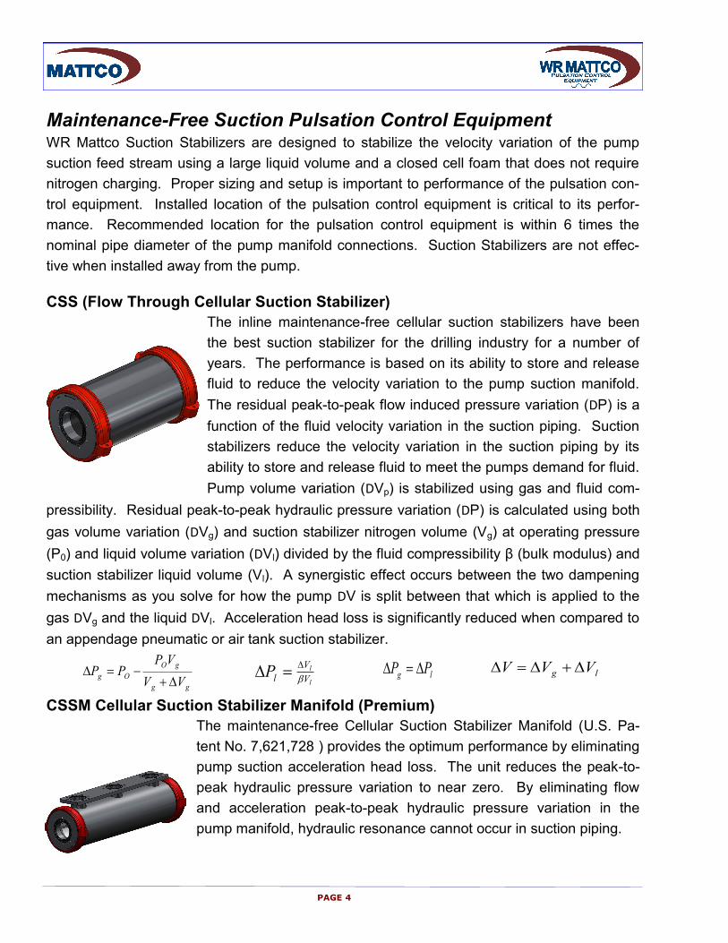
Maintenance-Free Suction Pulsation Control Equipment WR Mattco Suction Stabilizers are designed to stabilize the velocity variation of the pump
suction feed stream using a large liquid volume and a closed cell foam that does not require
nitrogen charging. Proper sizing and setup is important to performance of the pulsation con-
trol equipment. Installed location of the pulsation control equipment is critical to its perfor-
mance. Recommended location for the pulsation control equipment is within 6 times the
nominal pipe diameter of the pump manifold connections. Suction Stabilizers are not effec-
tive when installed away from the pump.
CSS (Flow Through Cellular Suction Stabilizer)
The inline maintenance-free cellular suction stabilizers have been
the best suction stabilizer for the drilling industry for a number of
years. The performance is based on its ability to store and release
fluid to reduce the velocity variation to the pump suction manifold.
The residual peak-to-peak flow induced pressure variation (DP) is a
function of the fluid velocity variation in the suction piping. Suction
stabilizers reduce the velocity variation in the suction piping by its
ability to store and release fluid to meet the pumps demand for fluid.
Pump volume variation (DVp) is stabilized using gas and fluid com-
pressibility. Residual peak-to-peak hydraulic pressure variation (DP) is calculated using both
gas volume variation (DVg) and suction stabilizer nitrogen volume (Vg) at operating pressure
(P0) and liquid volume variation (DVl) divided by the fluid compressibility β (bulk modulus) and
suction stabilizer liquid volume (Vl). A synergistic effect occurs between the two dampening
mechanisms as you solve for how the pump DV is split between that which is applied to the
gas DVg and the liquid DVl. Acceleration head loss is significantly reduced when compared to
an appendage pneumatic or air tank suction stabilizer.
CSSM Cellular Suction Stabilizer Manifold (Premium)
The maintenance-free Cellular Suction Stabilizer Manifold (U.S. Pa-
tent No. 7,621,728 ) provides the optimum performance by eliminating
pump suction acceleration head loss. The unit reduces the peak-to-
peak hydraulic pressure variation to near zero. By eliminating flow
and acceleration peak-to-peak hydraulic pressure variation in the
pump manifold, hydraulic resonance cannot occur in suction piping.
l
l
V
V
lP
gg
gO
OgVV
VPPP
PAGE 4
lg PP lg VVV
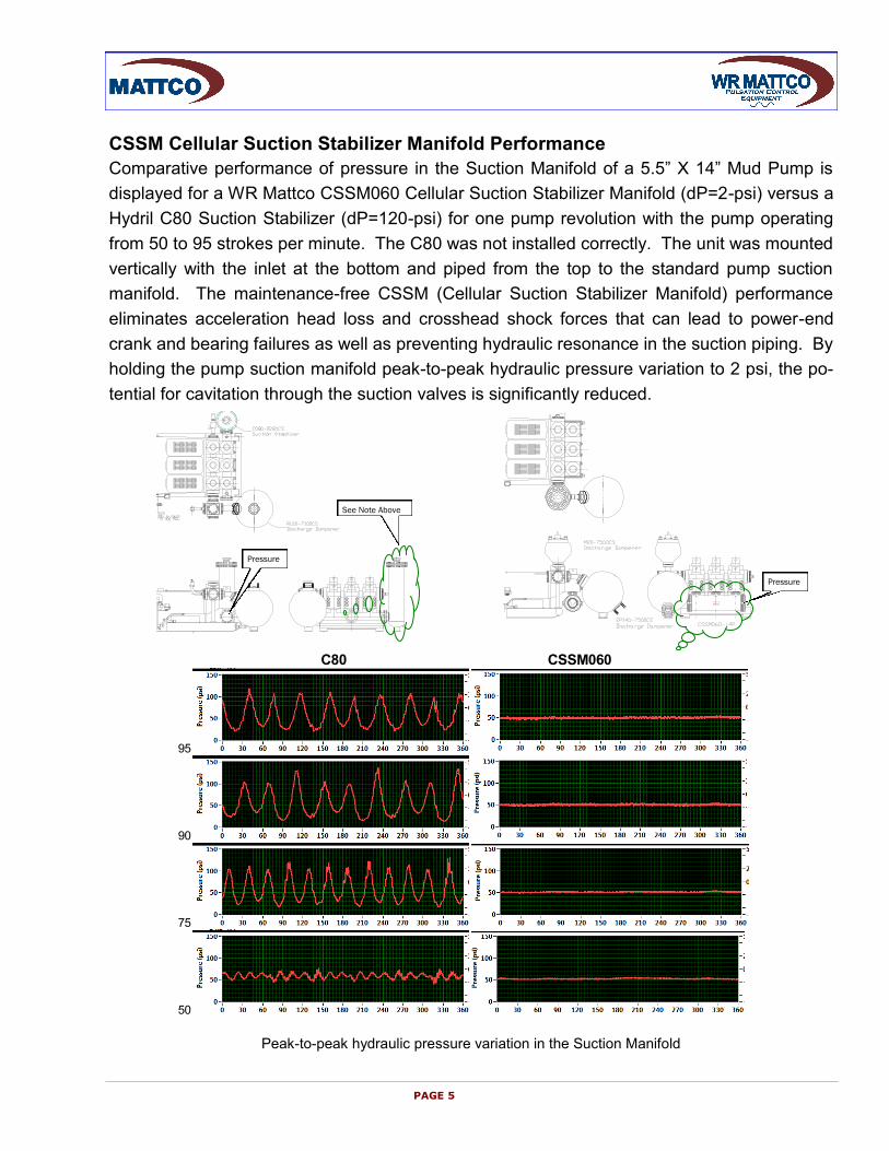
CSSM Cellular Suction Stabilizer Manifold Performance
Comparative performance of pressure in the Suction Manifold of a 5.5” X 14” Mud Pump is
displayed for a WR Mattco CSSM060 Cellular Suction Stabilizer Manifold (dP=2-psi) versus a
Hydril C80 Suction Stabilizer (dP=120-psi) for one pump revolution with the pump operating
from 50 to 95 strokes per minute. The C80 was not installed correctly. The unit was mounted
vertically with the inlet at the bottom and piped from the top to the standard pump suction
manifold. The maintenance-free CSSM (Cellular Suction Stabilizer Manifold) performance
eliminates acceleration head loss and crosshead shock forces that can lead to power-end
crank and bearing failures as well as preventing hydraulic resonance in the suction piping. By
holding the pump suction manifold peak-to-peak hydraulic pressure variation to 2 psi, the po-
tential for cavitation through the suction valves is significantly reduced.
Peak-to-peak hydraulic pressure variation in the Suction Manifold
PAGE 5
C80 CSSM060
95
90
75
50
Pressure
Pressure
See Note Above
Discharge Pulsation Control Equipment WR Mattco Pulsation Dampeners are designed to stabilize the velocity variation of the mud
pump. Proper sizing and setup is important to performance of the pulsation control equip-
ment. The pipe shaking load (F) is equal to the peak-to-peak hydraulic pressure variation
(DP) times the pipe cross section area (Ap). Location of the pulsation control equipment is
critical to its performance. Recommended location for the pulsation control equipment is with-
in 6 times the nominal pipe diameter of the pump discharge manifold. Discharge dampeners
are not effective when installed away from the pump.
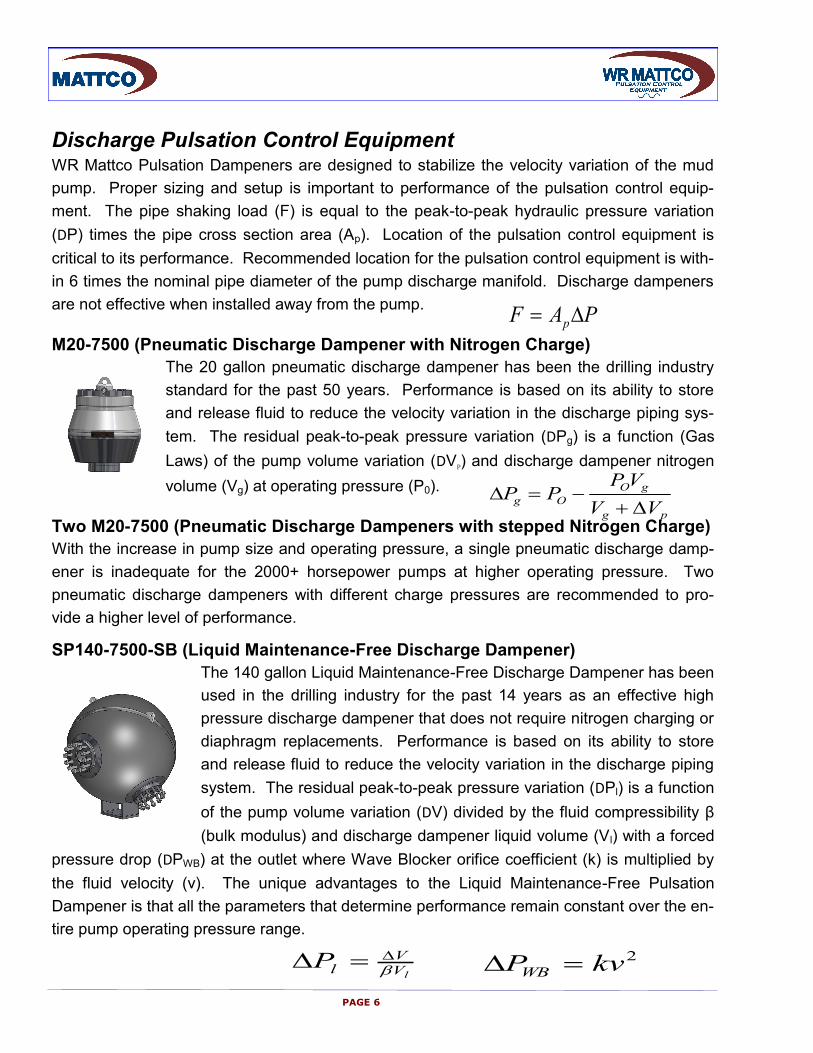
M20-7500 (Pneumatic Discharge Dampener with Nitrogen Charge)
The 20 gallon pneumatic discharge dampener has been the drilling industry
standard for the past 50 years. Performance is based on its ability to store
and release fluid to reduce the velocity variation in the discharge piping sys-
tem. The residual peak-to-peak pressure variation (DPg) is a function (Gas
Laws) of the pump volume variation (DVP) and discharge dampener nitrogen
volume (Vg) at operating pressure (P0).
Two M20-7500 (Pneumatic Discharge Dampeners with stepped Nitrogen Charge)
With the increase in pump size and operating pressure, a single pneumatic discharge damp-
ener is inadequate for the 2000+ horsepower pumps at higher operating pressure. Two
pneumatic discharge dampeners with different charge pressures are recommended to pro-
vide a higher level of performance.
SP140-7500-SB (Liquid Maintenance-Free Discharge Dampener)
The 140 gallon Liquid Maintenance-Free Discharge Dampener has been
used in the drilling industry for the past 14 years as an effective high
pressure discharge dampener that does not require nitrogen charging or
diaphragm replacements. Performance is based on its ability to store
and release fluid to reduce the velocity variation in the discharge piping
system. The residual peak-to-peak pressure variation (DPl) is a function
of the pump volume variation (DV) divided by the fluid compressibility β
(bulk modulus) and discharge dampener liquid volume (Vl) with a forced
pressure drop (DPWB) at the outlet where Wave Blocker orifice coefficient (k) is multiplied by
the fluid velocity (v). The unique advantages to the Liquid Maintenance-Free Pulsation
Dampener is that all the parameters that determine performance remain constant over the en-
tire pump operating pressure range.
lV
VlP
PAGE 6
pg
gO
OgVV
VPPP
PAF p
2kvPWB
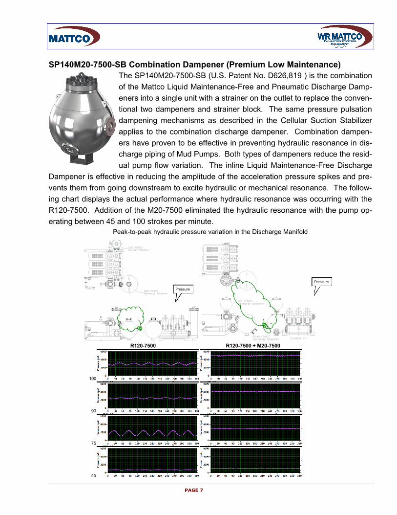
SP140M20-7500-SB Combination Dampener (Premium Low Maintenance)
The SP140M20-7500-SB (U.S. Patent No. D626,819 ) is the combination
of the Mattco Liquid Maintenance-Free and Pneumatic Discharge Damp-
eners into a single unit with a strainer on the outlet to replace the conven-
tional two dampeners and strainer block. The same pressure pulsation
dampening mechanisms as described in the Cellular Suction Stabilizer
applies to the combination discharge dampener. Combination dampen-
ers have proven to be effective in preventing hydraulic resonance in dis-
charge piping of Mud Pumps. Both types of dampeners reduce the resid-
ual pump flow variation. The inline Liquid Maintenance-Free Discharge
Dampener is effective in reducing the amplitude of the acceleration pressure spikes and pre-
vents them from going downstream to excite hydraulic or mechanical resonance. The follow-
ing chart displays the actual performance where hydraulic resonance was occurring with the
R120-7500. Addition of the M20-7500 eliminated the hydraulic resonance with the pump op-
erating between 45 and 100 strokes per minute.
Peak-to-peak hydraulic pressure variation in the Discharge Manifold
PAGE 7
R120-7500 R120-7500 + M20-7500
100
90
75
45
Pressure
Pressure

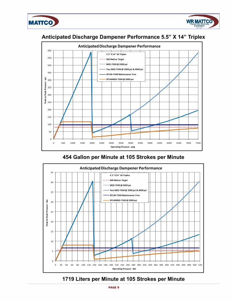
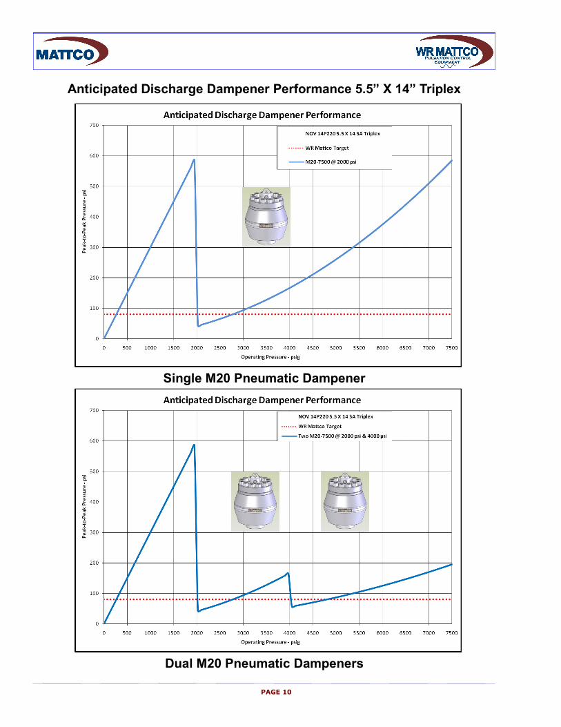
Anticipated Discharge Dampener Performance 5.5” X 14” Triplex
PAGE 8
A 14” Stroke Mud Pump with 5.5 inch liner delivers 454 gpm (1718 lpm) at 7475 psi (525.5
kg/cm2) when operating at 105 strokes per minute. The traditional discharge dampener sizing
criteria for mud pumps has been 3% of operating pressure. This design criteria is inadequate
with increased operating pressures and system complexity. Experience has shown that the
peak-to-peak hydraulic pressure variation must be below ~80 psi to prevent mud pump fluid
dynamic interaction with the mud pump discharge piping.
M20-7500 (Pneumatic Discharge Dampener with Nitrogen Charge)
A single 20 gallon pneumatic discharge dampener is totally inadequate because of very lim-
ited operating range and no dampening below the dampener charge pressure.
Two M20-7500 (Pneumatic Discharge Dampeners with stepped Nitrogen Charge)
Performance of two 20 gallon pneumatic discharge dampeners is marginal because of limited
operating range and none dampening below the dampener nitrogen charge pressure. In the
example of two pneumatic dampeners, there is potential damage to the diaphragm when op-
erating near 4000 psi.
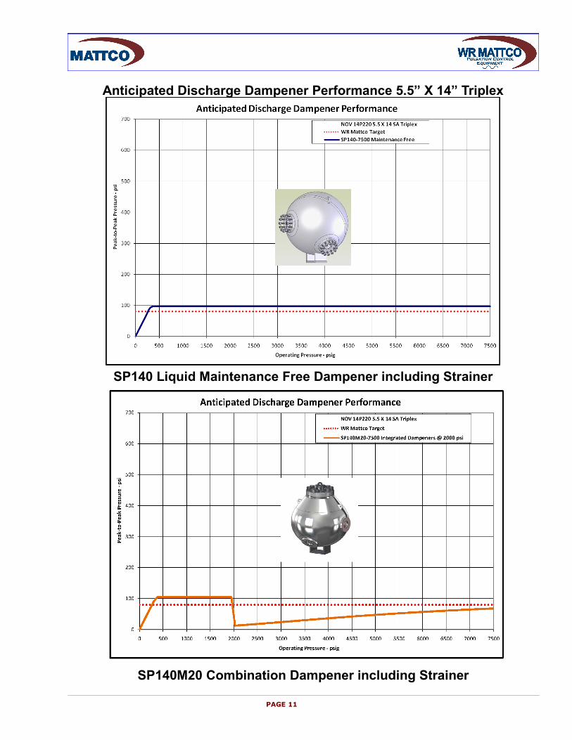
SP140-7500-SB (Liquid Maintenance-Free Discharge Dampener)
The 140 gallon liquid volume discharge dampener will provide a maximum peak-to-peak hy-
draulic pressure variation of 97 psi over the entire operating pressure range. However, de-
pending on mud pump discharge system configuration, hydraulic resonance can occur.
SP140M20-7500-SB Combination Dampener (Premium)
The SP140M20 is the integration of the Liquid Maintenance-Free and Pneumatic Discharge
Dampeners into a single discharge dampener. A Strainer/Wave Blocker is used on the
dampener outlet. The SP140M20 combination discharge dampener will provide a maximum
peak-to-peak hydraulic pressure variation of 117 psi when operating below the nitrogen
charge pressure and less than 73 psi when operating above.
PAGE 9
454 Gallon per Minute at 105 Strokes per Minute
1719 Liters per Minute at 105 Strokes per Minute
Anticipated Discharge Dampener Performance 5.5” X 14” Triplex
0
50
100
150
200
250
300
350
400
450
500
550
600
0 500 1000 1500 2000 2500 3000 3500 4000 4500 5000 5500 6000 6500 7000 7500
Pe
ak-t
o-P
eak
Pre
ssu
re -
psi
Operating Pressure - psig
Anticipated Discharge Dampener Performance
5.5" X 14" SA Triplex
WR Mattco Target
M20-7500 @ 2000 psi
Two M20-7500 @ 2000 psi & 4000 psi
SP140-7500 Maintenance Free
SP140M20-7500 @ 2000 psi
0
5
10
15
20
25
30
35
40
45
0 20 40 60 80 100 120 140 160 180 200 220 240 260 280 300 320 340 360 380 400 420 440 460 480 500 520
Pe
ak-t
o-P
eak
Pre
ssu
re -
Bar
Operating Pressure - Bar
Anticipated Discharge Dampener Performance
5.5" X 14" SA Triplex
WR Mattco Target
M20-7500 @ 2000 psi
Two M20-7500 @ 2000 psi & 4000 psi
SP140-7500 Maintenance Free
SP140M20-7500 @ 2000 psi
PAGE 10
Anticipated Discharge Dampener Performance 5.5” X 14” Triplex
Single M20 Pneumatic Dampener
Dual M20 Pneumatic Dampeners
PAGE 11
Anticipated Discharge Dampener Performance 5.5” X 14” Triplex
SP140 Liquid Maintenance Free Dampener including Strainer
SP140M20 Combination Dampener including Strainer
PAGE 12
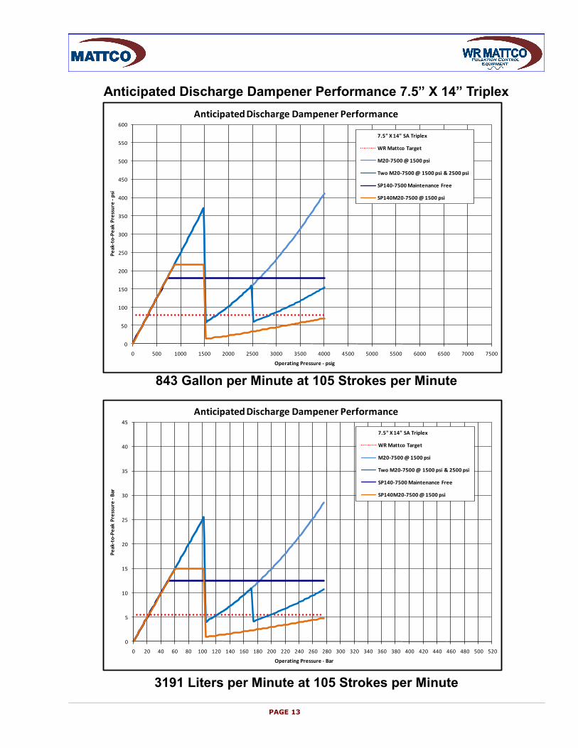
Anticipated Discharge Dampener Performance 7.5” X 14” Triplex
A 14” Stroke Mud Pump with 7.5 inch liner delivers 843 gpm (3191 lpm) at 4025 psi (277.5
kg/cm2) when operating at 105 strokes per minute. The traditional discharge dampener sizing
criteria for mud pumps has been 3% of operating pressure. This design criteria is inadequate
with increased operating pressures and system complexity. Experience has shown that the
peak-to-peak hydraulic pressure variation must be below ~80 psi to prevent mud pump fluid
dynamic interaction with the mud pump discharge piping.
M20-7500 (Pneumatic Discharge Dampener with Nitrogen Charge)
A single 20 gallon pneumatic discharge dampener is totally inadequate because of very lim-
ited operating range and no dampening below the dampener charge pressure.
Two M20-7500 (Pneumatic Discharge Dampeners with stepped Nitrogen Charge)
Performance of two 20 gallon pneumatic discharge dampeners is marginal because of lim-
ited operating range and none dampening below the dampener nitrogen charge pressure. In
the example of two pneumatic dampeners, there is potential damage to the diaphragm when
operating near 4000 psi.
SP140-7500-SB (Liquid Maintenance-Free Discharge Dampener)
The 140 gallon liquid volume discharge dampener will provide a maximum peak-to-peak hy-
draulic pressure variation of 180 psi over the entire operating pressure range. While the 180
psi peak-to-peak hydraulic pressure variation may be acceptable, this level of performance is
marginal because of the high potential of hydraulic resonance.
SP140M20-7500-SB Combination Dampener (Premium)
The SP140M20 is the integration of the Liquid Maintenance-Free and Pneumatic Discharge
Dampeners into a single discharge dampener. A Strainer/Wave Blocker is used on the
dampener outlet. The SP140M20 combination discharge dampener will provide a maximum
peak-to-peak hydraulic pressure variation of 218 psi when operating below the nitrogen
charge pressure and less than 69 psi when operating above.
PAGE 13
843 Gallon per Minute at 105 Strokes per Minute
3191 Liters per Minute at 105 Strokes per Minute
Anticipated Discharge Dampener Performance 7.5” X 14” Triplex
0
50
100
150
200
250
300
350
400
450
500
550
600
0 500 1000 1500 2000 2500 3000 3500 4000 4500 5000 5500 6000 6500 7000 7500
Pe
ak-t
o-P
eak
Pre
ssu
re -
psi
Operating Pressure - psig
Anticipated Discharge Dampener Performance
7.5" X 14" SA Triplex
WR Mattco Target
M20-7500 @ 1500 psi
Two M20-7500 @ 1500 psi & 2500 psi
SP140-7500 Maintenance Free
SP140M20-7500 @ 1500 psi
0
5
10
15
20
25
30
35
40
45
0 20 40 60 80 100 120 140 160 180 200 220 240 260 280 300 320 340 360 380 400 420 440 460 480 500 520
Pe
ak-t
o-P
eak
Pre
ssu
re -
Bar
Operating Pressure - Bar
Anticipated Discharge Dampener Performance
7.5" X 14" SA Triplex
WR Mattco Target
M20-7500 @ 1500 psi
Two M20-7500 @ 1500 psi & 2500 psi
SP140-7500 Maintenance Free
SP140M20-7500 @ 1500 psi
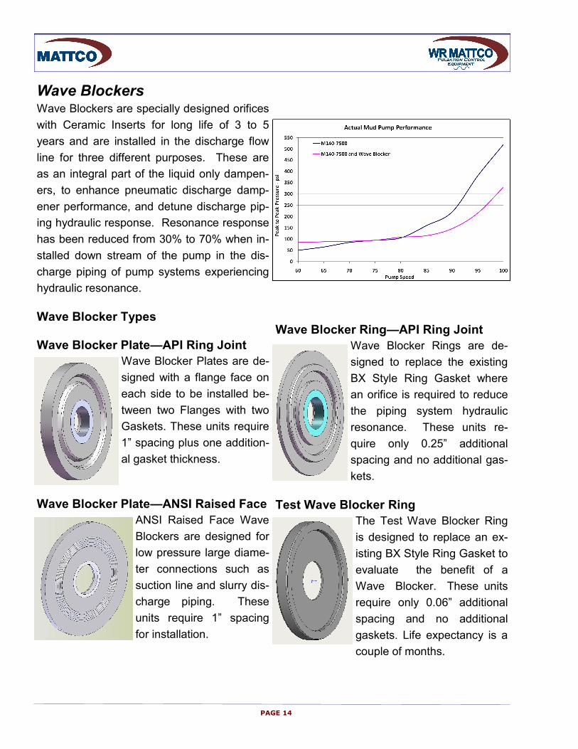
Wave Blockers Wave Blockers are specially designed orifices
with Ceramic Inserts for long life of 3 to 5
years and are installed in the discharge flow
line for three different purposes. These are
as an integral part of the liquid only dampen-
ers, to enhance pneumatic discharge damp-
ener performance, and detune discharge pip-
ing hydraulic response. Resonance response
has been reduced from 30% to 70% when in-
stalled down stream of the pump in the dis-
charge piping of pump systems experiencing
hydraulic resonance.
Wave Blocker Types
Wave Blocker Plate—API Ring Joint
Wave Blocker Plates are de-
signed with a flange face on
each side to be installed be-
tween two Flanges with two
Gaskets. These units require
1” spacing plus one addition-
al gasket thickness.
Wave Blocker Plate—ANSI Raised Face
ANSI Raised Face Wave
Blockers are designed for
low pressure large diame-
ter connections such as
suction line and slurry dis-
charge piping. These
units require 1” spacing
for installation.
Wave Blocker Ring—API Ring Joint
Wave Blocker Rings are de-
signed to replace the existing
BX Style Ring Gasket where
an orifice is required to reduce
the piping system hydraulic
resonance. These units re-
quire only 0.25” additional
spacing and no additional gas-
kets.
Test Wave Blocker Ring
The Test Wave Blocker Ring
is designed to replace an ex-
isting BX Style Ring Gasket to
evaluate the benefit of a
Wave Blocker. These units
require only 0.06” additional
spacing and no additional
gaskets. Life expectancy is a
couple of months.
PAGE 14
Wave Blocker Performance
The following figures display the relative and actual peak-to-peak hydraulic pressure variation
for a pipe header section of 270 feet operating with 6 pumps. The end pump was operating
at 33.3 strokes per minute.
Relative Peak-to-Peak Hydraulic Pressure Variation of 8.4 Hz Standing Wave along 270 ft Pipe Section
Wave Blockers installed in the header at Pumps 2 and 5 reduced the peak-to-peak hydraulic
pressure variation 38% by changing the frequency response of the piping. The high peak-to-
peak hydraulic pressure variation of 1194-kPa was occurring at the pump station’s discharge
piping 8.4 Hz half wave natural frequency when pumping water. After installation of the Wave
Blocker on the pump, the reduced peak-to-peak hydraulic pressure variation of 739-kPa was
at the normal pump excitation frequency of 3.3 Hz. The Wave Blockers are a custom product
that can be effectively applied with the assistance of WR Mattco.
Actual Peak-to-Peak Hydraulic Pressure Variation along 270 ft Discharge Pipe Section without Wave Blockers
Actual Peak-to-Peak Hydraulic Pressure Variation along 270 ft Discharge Pipe Section with Wave Blockers
PAGE 15
System Operating Conditions and Dynamics
Proper Mud Pump operation is dependent on adequate suction stabilizers and discharge
dampeners installed and working properly, and hydraulic resonance not occurring in the
piping system. All Mud Pumps have the potential to excite the piping mechanical and/or
hydraulic resonant frequencies. Excess hydraulic pressure variation will occur if the pump
excitation frequency matches the piping hydraulic resonant frequency. This process leads to
piping and piping system component failures, and premature relief valve activation as well as
mechanically over-stressing the Pump Fluid-End and Power-End.
Pumps generate two forms of hydraulic pressure disturbances in the suction and discharge
manifold and piping. These hydraulic pressure variations are the result of fluid flow and fluid
acceleration. A discussion of the pump cycle follows to understand the mechanisms that re-
sult in Pump Fluid Dynamics.
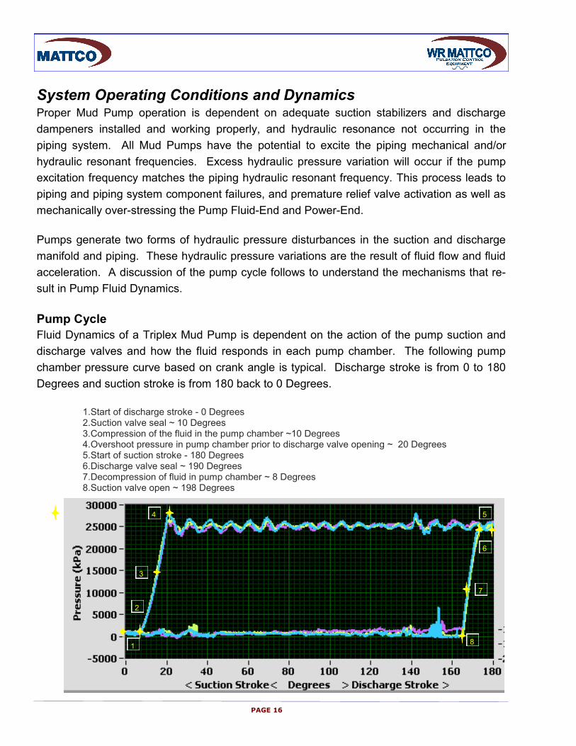
Pump Cycle
Fluid Dynamics of a Triplex Mud Pump is dependent on the action of the pump suction and
discharge valves and how the fluid responds in each pump chamber. The following pump
chamber pressure curve based on crank angle is typical. Discharge stroke is from 0 to 180
Degrees and suction stroke is from 180 back to 0 Degrees.
1. Start of discharge stroke - 0 Degrees 2. Suction valve seal ~ 10 Degrees 3. Compression of the fluid in the pump chamber ~10 Degrees 4. Overshoot pressure in pump chamber prior to discharge valve opening ~ 20 Degrees 5. Start of suction stroke - 180 Degrees 6. Discharge valve seal ~ 190 Degrees 7. Decompression of fluid in pump chamber ~ 8 Degrees 8. Suction valve open ~ 198 Degrees
1
2
3
4 5
6
7
8
PAGE 16
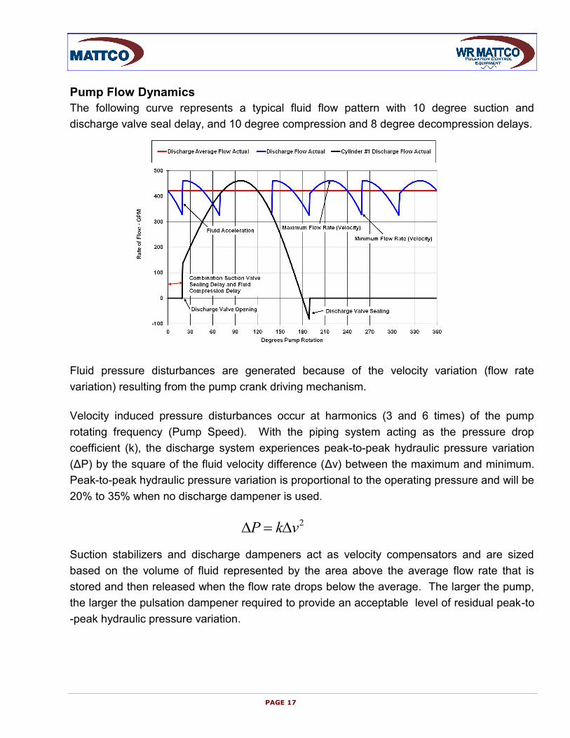
Pump Flow Dynamics
The following curve represents a typical fluid flow pattern with 10 degree suction and
discharge valve seal delay, and 10 degree compression and 8 degree decompression delays.
Fluid pressure disturbances are generated because of the velocity variation (flow rate
variation) resulting from the pump crank driving mechanism.
Velocity induced pressure disturbances occur at harmonics (3 and 6 times) of the pump
rotating frequency (Pump Speed). With the piping system acting as the pressure drop
coefficient (k), the discharge system experiences peak-to-peak hydraulic pressure variation
(ΔP) by the square of the fluid velocity difference (Δv) between the maximum and minimum.
Peak-to-peak hydraulic pressure variation is proportional to the operating pressure and will be
20% to 35% when no discharge dampener is used.
Suction stabilizers and discharge dampeners act as velocity compensators and are sized
based on the volume of fluid represented by the area above the average flow rate that is
stored and then released when the flow rate drops below the average. The larger the pump,
the larger the pulsation dampener required to provide an acceptable level of residual peak-to
-peak hydraulic pressure variation.
2vkP
PAGE 17
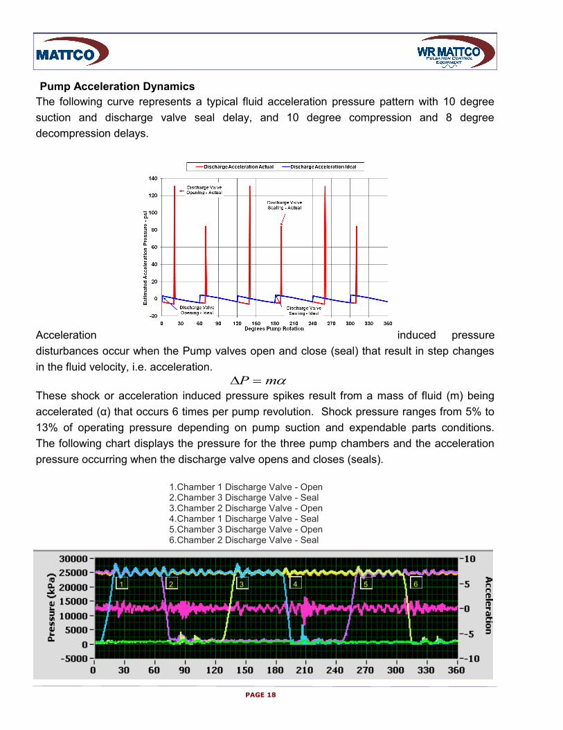
Pump Acceleration Dynamics
The following curve represents a typical fluid acceleration pressure pattern with 10 degree
suction and discharge valve seal delay, and 10 degree compression and 8 degree
decompression delays.
Acceleration induced pressure
disturbances occur when the Pump valves open and close (seal) that result in step changes
in the fluid velocity, i.e. acceleration.
These shock or acceleration induced pressure spikes result from a mass of fluid (m) being
accelerated (α) that occurs 6 times per pump revolution. Shock pressure ranges from 5% to
13% of operating pressure depending on pump suction and expendable parts conditions.
The following chart displays the pressure for the three pump chambers and the acceleration
pressure occurring when the discharge valve opens and closes (seals).
1. Chamber 1 Discharge Valve - Open 2. Chamber 3 Discharge Valve - Seal 3. Chamber 2 Discharge Valve - Open 4. Chamber 1 Discharge Valve - Seal 5. Chamber 3 Discharge Valve - Open 6. Chamber 2 Discharge Valve - Seal
mP
1 2 3 4 5 6
PAGE 18
Discharge Piping System Response
Pump suction and discharge piping system can have two forms of response to the fluid
dynamics. They are hydraulic and mechanical resonance that may result in excessive
mechanical stress of the pump and piping.
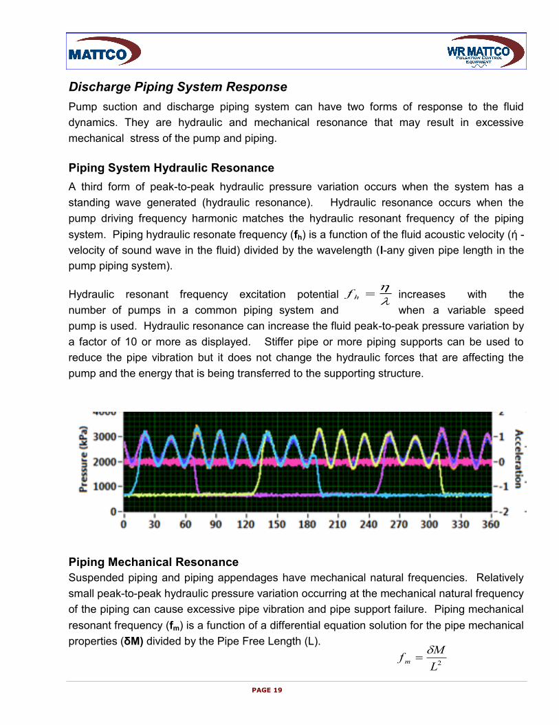
Piping System Hydraulic Resonance
A third form of peak-to-peak hydraulic pressure variation occurs when the system has a
standing wave generated (hydraulic resonance). Hydraulic resonance occurs when the
pump driving frequency harmonic matches the hydraulic resonant frequency of the piping
system. Piping hydraulic resonate frequency (fh) is a function of the fluid acoustic velocity (ή -
velocity of sound wave in the fluid) divided by the wavelength (l-any given pipe length in the
pump piping system).
Hydraulic resonant frequency excitation potential increases with the
number of pumps in a common piping system and when a variable speed
pump is used. Hydraulic resonance can increase the fluid peak-to-peak pressure variation by
a factor of 10 or more as displayed. Stiffer pipe or more piping supports can be used to
reduce the pipe vibration but it does not change the hydraulic forces that are affecting the
pump and the energy that is being transferred to the supporting structure.
Piping Mechanical Resonance
Suspended piping and piping appendages have mechanical natural frequencies. Relatively
small peak-to-peak hydraulic pressure variation occurring at the mechanical natural frequency
of the piping can cause excessive pipe vibration and pipe support failure. Piping mechanical
resonant frequency (fm) is a function of a differential equation solution for the pipe mechanical
properties (δM) divided by the Pipe Free Length (L).
hf
2L
Mfm
PAGE 19
PAGE 20
WR Mattco-PCEC 2011-07


