WRDC-TR-90-4066 AD-A227 709 MODELING OF STRESSES IN COATED SOLIDS Pradeep K Gupta Inc 117 Southbury Road Clifton Park, New York 12065 August 1990 Final Report for Period September 1989 - March 1990 Approved for public release; distribution unlimited IC MATERIALS LABORATORY /'NP. IGHT RESEARCH AND DEVELOPMENT CENTER AIR FORCE SYSTEMS COMMAND WRIGHT-PATIERSON AIR FORCE BASE, OHIO 45433-6533
Transcript
WRDC-TR-90-4066 AD-A227 709
MODELING OF STRESSES IN COATEDSOLIDS
Pradeep K Gupta Inc117 Southbury RoadClifton Park, New York 12065
August 1990
Final Report for Period September 1989 - March 1990
Approved for public release; distribution unlimited
IC
MATERIALS LABORATORY/'NP. IGHT RESEARCH AND DEVELOPMENT CENTER
AIR FORCE SYSTEMS COMMANDWRIGHT-PATIERSON AIR FORCE BASE, OHIO 45433-6533
NOTICE
WHEN GOVERNMENT DRAWINGS, SPECIFICATIONS, OR OTHER DATA ARE USED FOR ANYPURPOSE OTHER THAN IN CONNECTION WITH A DEFINITELY GOVERNMENT-RELATEDPROCUREMENT, THE UNITED STATES GOVERNMENT INCURS NO RESPONSIBILITY OR ANYOBLIGATION WHATSOEVER. THE FACT THAT THE GOVERNMENT MAY HAVE FORMULATED OR INANY WAY SUPPUIED THE SAID DRAWINGS, SPECIFICATIONS, OR OTHER DATA, IS NOT TOBE REGARDED BY IMPUCATION, OR OTHERWISE IN ANY MANNER CONSTRUED, AS UCENSINGTHE iHGLER, OR ANY OTHER PERSON OR CORPORATION; OR AS CONVEYING ANY RIGHTS ORPERMISSION TO MANUFACTURE, USE, OR SELL ANY PATENTED INVENTION THAT MAY IN ANYWAY BE RELATED THERETO.
THIS REPORT HAS BEEN REVIEWED BY THE OFFICE OF PUBLIC AFFAIRS (ASOIPA)AND IS RELEASABLE TO THE NATIONAL TECHNICAL INFORMATION SERVICE (NTIS). ATNTIS IT WILL BE AVAILABLE [0 THE GENERAL PUBUC INCLUDING FOREIGN NATIONS.
THIS TECHNICAL REPORT HAS BEEN REVIEWED AND IS APPROVED FOR PUBLICATION.
- ( -v
SHIASI K. SHARAI- Project Engineer B. D. McCONNELL, ChiefNonstructural Materials Branch
[ORTI IE COMMANDER
MNG - ~ir1.,it, MLRRIL~ol,. M1INGES, Direct
Nonmctallic Materials Division
IF YOUR ADDRESS HAS CHANGED, IF YOU WISH TO BE REMOVED FROM OUR MAIUNGLIST, OR IF THE ADDRESSEE IS NO LONGER EMPLOYED BY YOUR ORGANIZATION PLEASENOTIFY 'RJnuIJCM1B'T-r , WRIGHT-PATTERSON AFB, OH 45433- f.,m TO HELP MAINTAINA CURRENT MAILING LIST.
COPIES OF THIS REPORT SHOULD NOT BE RETURNED UNLESS RETURN IS REQUIRED BYSECURITY CONSIDERATIONS, CONTRACTUAL OB1IGATIONS, OR NOTICE ON A SPECIFICDOCUMENT.
I N CILASS 111 EDSE(URITY CLASSIFICATION OF THIS PAGE
Form ApprovedREPORT DOCUMENTATION PAGE 0MB No 0704-0188
6a NAME OF DERFORMING ORGANIZATION 6b OFFICE SYMBOL 7a. NAME OF MONITORING ORGANIZATION16(if applicable) Materials Laboratory (WRDC/k'LBT)Pradeep K Gupta Inc Wright Research and Development Center
6c. ADDRESS (City, State, and ZIP Codel 7b ADDRESS (City, State, and ZIP Code)117 Southbury Road Wright-Patterson AFB, OH1 451433-0533Clifton Park, New York 12065
Sa. NAME OF FUNDING/ SPONSORING Bb OFFICE SYMBOL 9 PROCUREMENT INSTRUMENT IDENTIFICATION NUMBERORGANIZATION I(if applicable)Materials Laboratory RD/LTF33615-89-C-5648
6c. ADDRESS (City, State, and ZIP Code) 10 SOURCE OF FUNDING NUMBERSMateialslabratoy (ASC)PROGRAM PROJECT TASKWOKUIW ,hL1,tv-onAB 1453053ELEMENT NO. NO NO ACCESSION NO
1'. K. Gupta and J. A. Walowit (Consultant)13a TYPE OF REPORT 1 3b rIME COVERED 14. DATE OF REPORT (Year, Month, Day) 1PAE COUNT
F inalI FROM SEP89 TO MAR9) 1990 August 06 T7 7116 SUPPLEMENTARY NOTATION
Small Business Innovation Research Program - Phase I
17. COSATI CODES 18. SUBJECT TERMS (Continue on reverse if necessary and identify by block number)FIELD G ROUtP SUJBGROUP Coatings Composites Solid Lubricants
Coated Solids Composite Materials
LLayered Solids Surface Films19. ABSTRACT (Contmouc on reverse if necessary anid identify by block number)
A I ilite' ele(Ment approach to model stress distributions in coated sol ids is developed. l*Iepersonal computer blased PC-ANSYS code is used to implement thle approachl on a personalcompu)IteIr system11. The three types of houndary loadign considered are' an ell iptical normalpress-ure distribution, a shear stress distribution proportional to thle normlal pressure, anda thermial flux proportional to the surface shear. The model predictions are validatedagainst the classical Hertz theory and plane-pstrain solution obtained independently by w~ellestablished Fourier transform approaches. The deviations of the finite element model frTItile other available solutions is found to be less than 1%.. Parametric results of the modelestablish practical significance of the modeling approach for optimization of coatingthickness, materials selection, and for the development of coating application techniqujesand T)snr ed tres to ensure acceptable "break-away" stresses in the coating and at thecoating/suibstrate interlace. Extiension of the finite element approach to the modeling ofcomlpex three-dlimenfsional contacts is demonstrated by mlodeling a rectangular contact over
20 D1STRIBUTON'AVAII.ABIIIrY 0 ABSTRACT 21 ABSTRACT SECURITY CLASSIFICATIONOUJNCI ASSIFIEDINI IMITF[) Li SAME AS RPT U] TIC IJS[RS Unc1 rlas s if ied
7,a %AME OF RESPONSIRI C FNIIVIDIJAI 2 2b T ELE PHONE (include Area Code) 2 2 011( 1 ~V VBO;
SH1ASFII K. ;HAJ IA (513) 255-9029 1 1N Dc/mIWI'DD Form 1473, JUN 86 Previous editions are obsolete SECURITY CtASSIFICATION 01 THIS PA6E
I IN C LA S I 1 lIIl
Block 19 continued
a semi -infinite solid. This preliminary three-dimensional model, along with thetwo-dimensional parametric results demonstrate technical feasibility of theoverall modeling approach. In addition, the results provide a strong analyticalfoundation for the development of a more rigorous and sophisticated models, andextended data bases for practical design of interacting coated solids for awide range of practical applications. (
FOREWORD
This research was sponsored by the United St-ites Air Force uinder the Defense SmallBusiness Innovation Research (SBIR) Program, Air Force Contract Number F3136 15-89-C-5648. The Air Force Project Engineer was Mr. Shashi K. Sharma (WRDC/MLBT).The workreported herein constitutes Phase I effort of the overall program.
Accc!79G I c,
NTIS ~C'x
DTIC TAB
Justificatio
By__ __ _
~Avallnbililv CodesL 7do
Diec cin I
Table of Contents
1. INTRODUCTION 1
2. ANALYTICAL APPROACH 32.1 Finite Element Modeling 32.2 Numerical Integral Model 10
3. RESULTS 143.1 Model Validation 143.2 Parametric Studies 203.3 Three Dimensional Finite Element Modeling 45
4. SUMMARY 53
5. RECOMMENDATIONS FOR FUTURE DEVELOPMENT 55
REFERENCES 57
APPENDIXThermal Analysis of Semi-infinite Solid with aMoving Heat Source 59
1. INTRODUCTION
The tribological behavior of the materials present at the interface between machineelements subjected to sliding interaction very often dominate the overall behavior and life ofthe entire mechanical system. Friction and wear of bearings, gears, cams and similar compo-nents, is a significant problem in a wide range of both DOD and commercial applications. Theuse of lubricating oils and greases is well known for reduction of friction and wear and as aresult improvement in life of the overall mechanical system. However, these conventionallubricants can only perform satisfactorily in a limited range of operating temperatures. In thevery high temperature environment of modern gas turbine applications, solid lubricants offer,perhaps, the only means of lubricating the interacting mechanical elements. Similarly atcryogenic temperatures, solid lubrication offers the only potential for reducing friction andwear between mating surfaces. Very often solid lubrication under the extreme operatingenvironments is accomplished by applying one or more coatings of certain materials, whichoffer favorable tribological characteristics, to the mating surfaces. Quite often several thincoats of different materials may be used or certain composite materials may offer favorablefriction and wear characteristics. The thermo-mechanical behavior of the coatings may varyfrom fully isotropic to highly anisotropic. In general, due to the greatly different constitutivebehavior of the coatings compared to that of the substrate, an acceptable design of a coating-substrate system is dependent on realistic modeling of the stresses in the coatings in aprescribed operating environment. The stress distribution in the coating determines itsmechanical survival; the tensile stresse, in the coating are often responsible for fractureinitiation while both the shear and tension at the coating/substrate interface affects theadhesion, or mechanical bond, of the coating to the substrate. A rigorous analytical modelingof these stresses as a function of materials properties and coating thickness is, therefore,essential. In addition to the prediction of optimum values of coating thickness for prescribedmaterials in a given operating environment, the models may be used to parametrically evaluatecritical design parameters, such as shear and tensile stresses at the coating to substrateinterface, thermal stresses induced by the difference in thermal coefficient of expansionbetween the Coatings and substrate and realistic endurance limits when the coated elementsare subjected to cyclic loading, to arrive at significant recommendations for the requiredmaterials for more advanced applications. The development of analytical models to computethe thermo-mechanical behavior of coated solids is, therefore, the primary objective of thisproject.
Due to a rather wide application potential, the analytical modeling of the contactmechanics and interfacial interactions in coated solids has been of significant interest in therecent years. In the past, b)th the solution to the contact problem and the stress distributionin the coating as a function of the prescribed boundary loading have been attempted. Thesolution to the contact pressure profile in the case of cylindrical contact between coated elasticsolids has been obtained to varying degrees of sophistication by a number of investigators [ 1-8].Most ()f the early work [1-5] considered an asymptotic problem of a very thin or thick coating.Meijers [5], while considering an elastic layer over a rigid substrate demonstrated that thesolutions for a thin and thick layer overlap so well that these solution may apply to arbitrarylayer thicknesses with excellent approximation. Wu, Chiu and Pao [6,7] considered the classicalstress function approach to the contact problem of coated solids, and they clearly demonstrated
the mathematical complexity of the problem, particularly the numerical convergence problemas the material of the coating tends to become incompressible. Gupta and Walowit [81 resolvedthis problem by considering a Fourier transform of the Airy stress function and they obtainedsolutions where both the coating thickness and the coating to substrate modulus ratios mayassume arbitrary values; in addition, they demonstrated that the Poisson's ratio may also bearbitrary and therefore, the incompressible materials may be properly modeled. In the areaof stress distribution in the coating, most investigators considered either a uniform or anelliptical boundary loading. Lemcoe [9] considered a uniform pressure over the contact zoneon a hard coating resting over a relatively soft substrate. Results for the stress distribution inthe coating and substrate were presented for the cases when the coating is either in frictionlesscontact or bonded to the substrate. Barovich, et al. [10], used an elliptical pressure profile andobtained stress distribution when the ratio of modulus of elasticity of the coating to that of thesubstrate varied in the range of 0.25 to 4. Later Ku, et al. [11], considered surface shear andpresented similar results for both elliptical and uniform shear prescribed at the coating surface.Based on the general solution to the contact problem [8], Gupta, Walowit and Finkin [12]considered an arbitrary pressure and shear loading on the coating surface, and they presentedresults for stress distribution in the coating, substrate and at the coating/substrate interface fora wide range of material properties. For practical designs, the work of Gupta and Walowit[8,12] has been implemented in a FORTRAN computer code, LAYER [ 13], which is presentlyoperational on personal computer systems.
With particular emphasis on both DOD and commercial application, the modelsdiscussed above have several limitations; first, most of the models are restricted to a onecoating system; second, essentially all of the modeling effort has been dedicated to thesimulation of mechanical loadings and the thermal problem has been greatly neglected; finally,the modeling process has been restricted to fairly well defined plane strain contacts andapplication to real practical components with complex geometries, such as bearings and gears,has been restricted. Since, on tribological grounds, there is a definite potential for the use ofmulticoated configurations and substantial thermal gradients are often present, refinementsof the current models to help eliminate both these restrictions are essential for the develop-ment of viable analytical tools. In addition, analytical techniques for developing realisticsolutions for complex geometries and simulations of three-dimensional contacts are essentialfor the performance predictions of practical components. The recent advancements in finiteelement methods offer substantial potential in this area. The finite element algorithms permitmodeling of all geometrical and thermal effects. However, before the model can be used forpractical design, validation against other numerical solutions and experimental data is essen-tial. An advancement of the current models for plane strain contacts and the initial formulationfor a finite element model are, therefore, the objective of Phase I of the proposed projec t .Thetechnical feasibility of the finite element approach is proven by validating the solutionsobtained under plane strain conditions against similar solutions obtained by other provennumerical techniques for such simplified contact geometries. In addition, the practical signif-icance of the modeling approach is demonstrated by parametric computer runs which showthe variation of stresses as a function of material properties and coating thickness. Thus, theoverall feasibility of the modeling approach for materials selection and practical design in agiven operating environment is demonstrated.
2. ANALYTICAL APPROACH
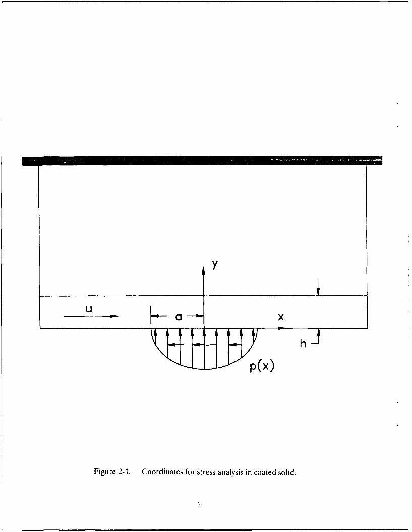
The contact problem of a coated solid is shown schematically in figure 2-1, where acoating of finite thickness is applied to a semi-infinite substrate. Under simplified plane strainconditions, such a configuration could simulate either a pure rolling contact, or a combinedrolling-sliding contact as would occur in rolling element bearings, gears or cams. The ellipticalloading, shown in the figure, may have three components: normal loading, shear loading andthermal loading. For normal loading, the pressure distribution p(x), for a Hertzian line contactis given by the relationship
where pl is the maximum Hertz pressure and a is the contact half width.
The surface shear loading r(x), corresponding to a prescribed friction or tractioncoefficient,,u , may be written as a product of the normal contact pressure and the tractioncoefficient
T(x) = I' p(x) (2)
If the slip rate between the two interacting surfaces is u, then the thermal loading wouldarise from the flux, (p, dissipated into the coated surface, which is given by the relationship
P (x) = /3 /up x) (3)
where /3 is fraction of heat transferred to the coated surface under consideration while theremainder goes to the other surface.
Using the above three types of general loading, two different analytical approaches areconsidered: a finite element approach which permits modeling of any geometry and a Fouriertransform approach which provides numerically accurate solutions for a simplified contactgeometry. With the ultimate objective of developing viable design tools for a wide range ofpractical applications, the technical feasibility of finite element approach is demonstrated byvalidation of the finite element solutions against corresponding solutions obtained by theFourier transform approach and the classical Hertz contact theory. The highlights of bothapproaches are briefly discussed below.
2.1 Finite Element Modeling
The two of the most commonly available finite element codes are NASTRAN and
3
Ua x
Figure 2-1. Coordinates for stress analysis in coated solid.
4
ANSYS. Both of these packages have the capability of modeling all three types of loadingdiscussed above. However, ANSYS is readily available for personal computers, and itsinteractive user interfaces are, perhaps, more developed for efficient solutions of a wide rangeof problems on a personal computer. Due to such a readily available capability, ,he PC-ANSYSis selected for the present investigation, although the personal computers are still limited interms of overall computing power required for sophisticated finite element modeling. Oncethe overall technical feasibility of the finite element approach is proven in the present PhaseI effort, a more rigorous modeling shall be undertaken in the second phase of this project. Infact, as will be discussed later, the use of NASTRAN may be more appropriate in Phase II,since it is presently supported on the ASD computer system at Wright-Patterson Air ForceBase. The transition from PC to main frame, or even from ANSYS to NASTRAN is indeedquite straightforward.
Similar to NASTRAN, ANSYS runs in three stages: a preprocessor, the main processorand a postprocessor. The preprocessor generates an input file for the main processor which,in turn, generates the stiffness matrices, computes element solutions and generates a binaryoutput file for postprocessing. The postprocessor takes the output file and generates ASCIItext and graphical outputs.
For the present problem, the element type and geometry, material properties and themechanical and thermal loading parameters are all input via the preprocessor. Although thenormal loading can be specified directly in terms of the prescribed contact pressures, the shearloading needs to be input in terms of forces at each node on the surface. In addition, the thermalloading is input in terms of a temperature field. The temperatures at each of the nodes aregenerated from a finite difference analysis, described in the Appendix. To prescribe all theseinputs efficiently a personal computer based "pre-preprocessor" program has been written.This program generates the grid points (either automatically or from the optional user supplieddata), computes temperatures at each point, computes normal and shear nodal forces on thesurface and transmits all the data to input file as required by the ANSYS preprocessor.Installation of this input data preparation program to the main frame computer system, inPhase II, is quite straightforward.
Similar to the input data preparation effort, some analysis of the output from theANSYS postprocessor is required for efficient handling of the output data. Thus a "post-postprocessor" is written to provide some degree of database management of multiple ANSYSoutput files, provide means for superposition of stresses obtained from various solutions,enable extended data reductionl in the form of additional dimensionless quantities, provideimproved output quality with convenient units and smoothing, and finally to obtain usable hardcopy. Again, transfer of this procedure for use on main frame computer system, in Phase II,can be very easily carried out.
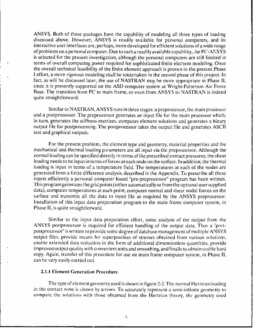
2.1.1 Element Generation Procedure
The type of element geometry used is shown in figure 2-2. The normal lertzian loadingin the contact zone is shown by arrows. To accurately represent a semi-infinite geometry tocompare the solutions with those obtained from the Hertzian theory, the geometry used
5
x O
extends 100 half widths in the positive and negative x andy directions.
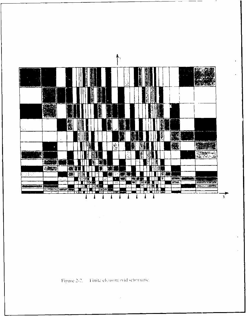
Four node isoparametric elements with two degrees of freedom at each node are usedin all two dimensional models. In order to capture rapid variations and produce accuratesolutions, very fine mesh sizes are required in the y direction near the surface and near thecoating to substrate interface. Also, due to the elliptical variation of surface loading, fine meshsizes are needed near the edges of the contact. The method of mesh generation is illustratedin figure 2-3 which presents an enlarged view of the element geometry near the contact zone.The minimum mesh size, location of the outer boundaries, and the number of grid points ineach direction are taken as inputs. Values for these quantities are dictated by trade-offsbetween overall accuracy, available storage and computing speed. In the absence of a coating,the minimum mesh size iny direction is used at the surface. An appropriate ratio, r, is calculatedso that the length of each successive element in they is r times that of the preceding elementand the outer boundary is reached at the prescribed number of mesh points. A similarprocedure is used for x direction. The x grid is taken to be symmetric about the center ofcontact. The prescribed minimum grid size in the x direction is used at the edge of contact.The number of elements between the center and edge of contact, and between the edge andouter boundary, are equal. Appropriate r values are calculated for each region.
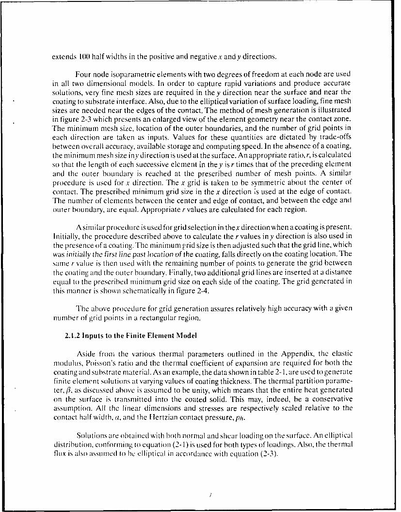
A similar procedure is used for grid selection in thex direction when a coating is present.Initially, the procedure described above to calculate the r values iny direction is also used inthe presence of a coating. The minimum ,rid size is then adjusted such that the grid line, whichwas initially the first line past )ocation of the coating, falls directly on the coating location. Thesame r value is then used with the remaining number of points to generate the grid betweenthe coating and the outer boundary. Finally, two additional grid lines are inserted at a distanceequal to the prescribed minimum grid size on each side of the coating. The grid generated inthis manner is shown schematically in figure 2-4.
The above procedure for grid generation assures relatively high accuracy with a givennumber of grid points in a rectangular region.
2.1.2 Inputs to the Finite Element Model
Aside from the various thermal parameters outlined in the Appendix, the elasticmodulus, Poisson's ratio and the thermal coefficient of expansion are required for both thecoating and substrate material. As an example, the data shown in table 2-1, are used to generatefinite element solutions at varying values of coating thickness. The thermal partition parame-ter, fl, as discussed above is assumed to be unity, which means that the entire heat generatedon the surface is transmitted into the coated solid. This may, indeed, be a conservativeassumption. All the linear dimensions and stresses are respectively scaled relative to thecontact half width, a, and the Ilertzian contact pressure, ph.
Solutions are obtained with both normal and shear loading on the surface. An ellipticaldistribution, conforming to equation (2-1) is used for both types of loadings. Also, the thermalflux is also assumed to be elliptical in accordance with equation (2-3).
7
~71
1' i L re 2-. (rid SItrUctire near the contact with coating.
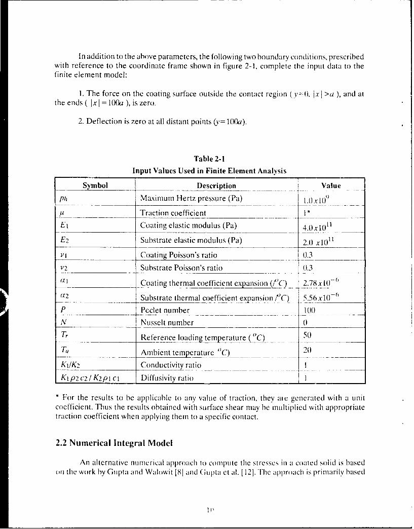
In addition to the above parameters, the following two boundary conditions, prescribedwith reference to the coordinate frame shown in figure 2-1, complete the input data to thefinite element model:
1. The force on the coating surface outside the contact region (y=(), IxI >a ), and atthe ends ( Ix I = 100a ), is zero.
2. Deflection is zero at all distant points (y= 10a).
Table 2-1Input Values Used in Finite Element Analysis
For the results to be applicable t any value of traction, they are generated with a unitcoefficient. Thus the results obtained with surface shear may be multiplied with appropriatetraction coefficient when applying them to a specific contact.
2.2 Numerical Integral Model
An alternative numerical approach to C011pUte the stresses in a coated solid is basedon the work by Gupta and Wahiwit [8] aid (Gupta et al. [121. The approach is primarily based
I )
on a plane strain formulation derived from the Fourier transform of the classical Airy stressfunction. With reference to the coordinate frame shown in figure 2-1, the stresses
Jx, ay, and rA-v, are respectively given by the relations:
2_ 1 A _ 00 d2G -iwx
ay - 00 dy2 (2-4)
'Iy - ax2 f 2 0~ wo 2 G e -'xdo)
2r -0 (2-5)
TAY a 1 f ) -=.G x dwl-X-y 2t dy (2-6)
where V) is the Airy stress function which satisfies the biharmonic equation and G is the Fouriertransform of ip, symbolically,
V4 p=(0 (2-7)
and
G = lp eix dxG f 0 o
(2-8)
Also, the normal strains, Ex and E,, and the displacements, u and v, along the x and ydirection are given by
1[ V2 ) V + V ]
E =(1-v);v-v(l+v)Ux (2-19)
E~ (2-10-
U = - .- "- -- 2 + a)2 G27E - 00 dy -- v, (2- 11
f-TE -(oo dy 3 - ieVv (2-12)
where E is the elastic modulus and v is the Poisson's ratio.
By eliminating ip in equations (2-7) and (2-8), and by solving the resulting differentialequation in G, the general solution may be shown to be of the form
G = ( A + By )e- I ly + ( C + Dy ) e+ II Y (2-13)
whereA, B, C and D may, in general be functions ofaw and they are determined by appropriateboundary conditions.
In the absence of any thermal effects or temperature fields., the boundary conditionsfor the coating/substrate system, as shown schematically in figure 2-1, may be readily expressedas
(,y 0 - p(x) (2-14a)
(rxy1) q (x ) (2-14b)
( yl = Y2 Y2 = 0 (2- 14c)
SY = (TAY) Y2 0 (2-14d)
(U) = (U) = 0 (2-14c)
( '1 = V2) = 0 (2-14f)
2 y = 2-14g)
1 2
2 = 00 (2-14h)
where the subscripts I and 2 denote the coating and substrate respectively. The variables viandy2 are measured respectively from the coating surface and the coating/substract interface.
The above eight boundary conditions result in eight simultaneous algebraic equationsfor the coefficients .41, B1, C1. I),.42, B2, C2, D2. Obviously conditions (2-14g) and (2-14h)result in C2 = D2 = 0). The remaining six algebraic equations are easily solvable for prescribedsurface pressure, p(x), and surface shear, q(x).
Although when the coating is bonded to the substrate the strains are always continuousat the interface, the influence of different thermal coefficient of expansion is modeled, as afirst approximation, in terms of a discontinuous strain boundary condition . Thus for atemperature rise, T, at the coating/substrate interface, the boundary condition (2-14f) isreplaced by
)'1 = h- ( f ) (al - a2) T (2-15)
where al and a2 are the thermal coefficient of expansion respectively for the coating andsubstrate, and T is the temperature rise above nominal conditions.
In the absence of a rigorous thermal analysis, we further assume that the temperatureprofile at the coating/substrate interface is proportional to the contact pressure at the coatingsurface. Thus, for any prescribed maximum temperature in the contact, the required temper-ature profile is computed from the given pressure distribution at the coating surface.
Based on the above analytical formulation, the available computer code LAYER ismodified for the thermal boundary condition (2-15). Such a modified version provides resultsto assess the significance of the thermal mismatch in properties of the coating and substrate.A more detailed analysis shall be undertaken in the second phase of this project, where adetailed temperature field, as presently computed for the finite element, shall be incorporatedin the numerical integral solution model.
Io compare the results from the finite element model with those obtained with theabove numerical formulation, parametric runs are made with identical material properties andcoating thickness. In addition, some parametric runs are made as a function of varying materialproperties, coating thicknesses and operating temperatures to establish the practical designsignificance of the overall modeling approach.
3. RESULTS
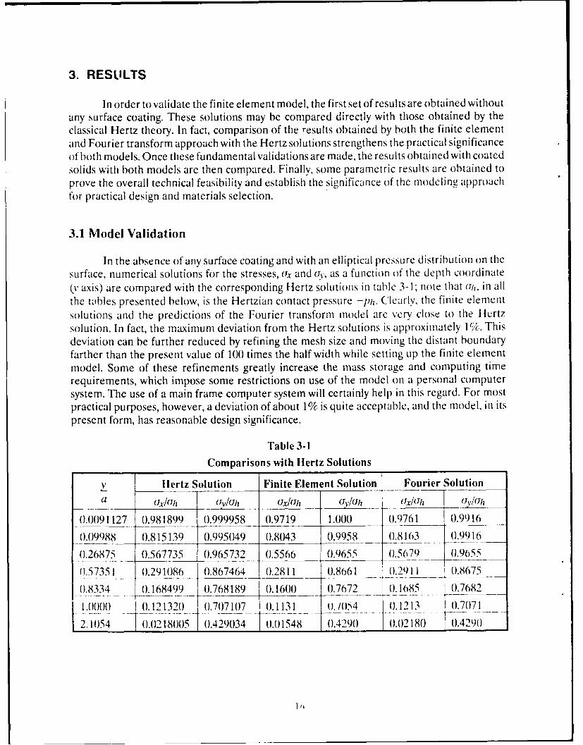
In order to validate the finite element model, the first set of results are obtained withoutany surface coating. These solutions may be compared directly with those obtained by theclassical Hertz theory. In fact, comparison of the results obtained by both the finite elementand Fourier transform approach with the Hertz solutions strengthens the practical significanceof both models. Once these fundamental validations are made, the results obtained with coatedsolids with both models are then compared. Finally, some parametric results are obtained toprove the overall technical feasibility and establish the significance of the modeling approachfor practical design and materials selection.
3.1 Model Validation
In the absence of any surface coating and with an elliptical pressure distribution on thesurface, numerical solutions for the stresses, (x and ur, as a function of the depth coordinate(y axis) are compared with the corresponding Hertz solutions in table 3-1; note that Uls, in allthe tables presented below, is the Hertzian contact pressure -pi. Clearly, the finite elementsolutions and the predictions of the Fourier transform model are very close to the Hertzsolution. In fact, the maximum deviation from the Hertz solutions is approximately 1c. Thisdeviation can be further reduced by refining the mesh size and moving the distant boundaryfarther than the present value of 100 times the half width while setting up the finite elementmodel. Some of these refinements greatly increase the mass storage and computing timerequirements, which impose some restrictions on use of the model on a personal computersystem. The use of a main frame computer system will certainly help in this regard. For mostpractical purposes, however, a deviation of about 1% is quite acceptable, and the model, in itspresent form, has reasonable design significance.
Table 3-1
Comparisons with Hertz Solutions
V lertz Solution Finite Element Solution Fourier Solutionaa (Jly/avU/ USx/Uh icY.2,lo (x/U/, (.s/lJ/
Similar to the finite element model, the grid size and the upper limits of integrationused while performing a Fourier transform, may further improve the accuracy of the predictedresults. For practical purposes, once again, the results are quite acceptable since the deviationis no more that 1%.
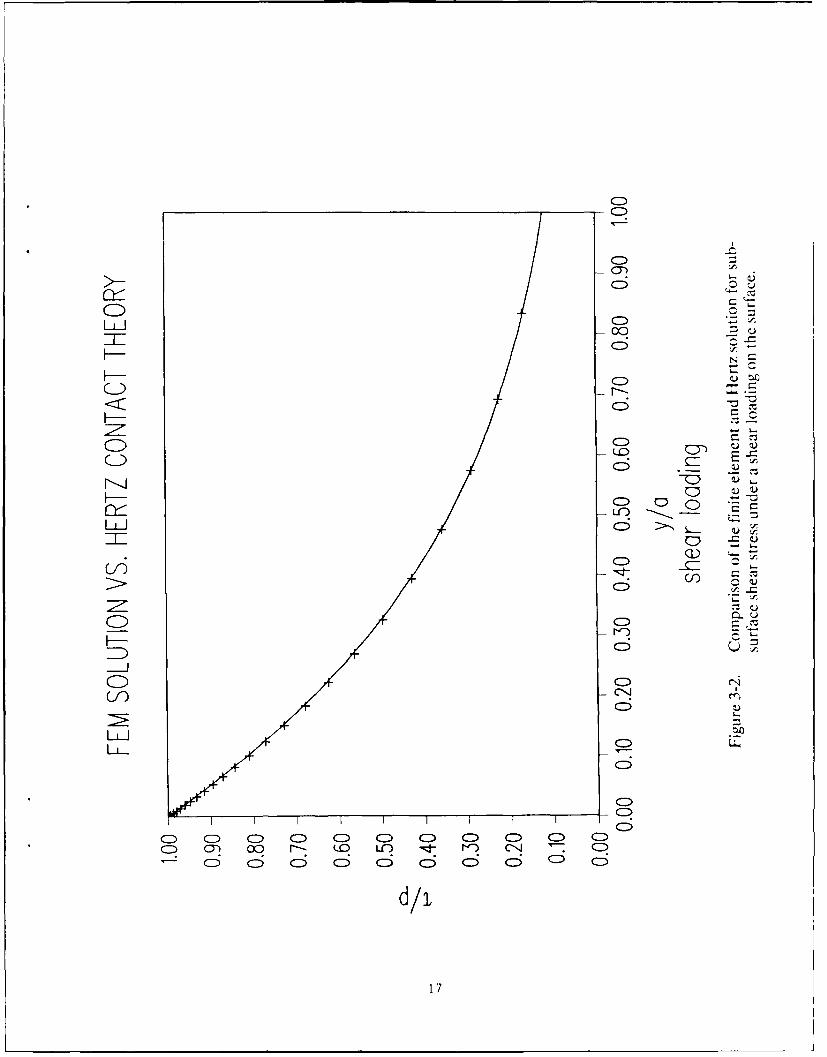
Perhaps the most interesting case for validation of the finite element model is tocompare the stress uZ , on the surface as generated by a shear loading. With the selected meshsize, it is confirmed that the deviation of the numerical results from the Hertzian solutions iswithin the above 1% limit. The comparison is shown graphically in figure 3-1, where themarked points represent finite element solution and the solid line represents the Hertz theory.The corresponding comparisons of the shear stress as a function of depth are shown in figure3-2. Again, the model predictions are quite acceptable.
Another set of results is obtained with coated solids with both the finite element andFourier transform approach. For a normal elliptical pressure loading on the surface, compar-ison of predicted stresses versus depth atx = 0, by the two models are shown in tables 3-2 and3-3 respectively for the coating thickness to contact half width ratios (a/h) of 0.25 and 0.50.Clearly, the solutions are very close to each other. In fact, the deviation is of the same generalorder as that seen above while comparing the solutions with the Hertz theory.
For an applied elliptical shear loading on the coating surface, the predicted distributionof shear stress, at x = 0, as a function of depth by the two models are compared in tables 3-4and 3-5. Once again, the deviations between the two solutions are quite small, and both modelsare in good agreement with each other.
The above results clearly prove the validity of both models. Both the finite element orthe Fourier transform approach provide acceptable prediction of stresses in coated solids. Interms of actual implementation for practical design, the finite element model can be effectivelyused for arbitrarily complex geometries, while the integral formulation is limited to simplifiedcontact configurations. On the other hand, the finite element models require some effort inthe pre and postprocessing of the data and overall setup of the problem, while the use of thenumerical integral model is very straightforward. Thus depending on complexity of theapplication, both models may have a notable practical significance. For material selection andpreliminary design, the Fourier transform approach may be very efficient, while for final designdevelopment for critical and complex applications, the finite element approach may provideacceptable design solutions with minimum number of model assumptions and limitation. Fora more "friendly" implementation, both models may be run over a wide range of contactconfigurations and material properties, and a design data base may be generated to catalogthese solutions over a wide range of applications. For a specific design, the data base can thenprovide very quick and accurate answers to a range of practical problems. The strengths of themodels in generating such a data base is demonstrated by the parametric runs discussed next.
I1r
CND
CN
F- CDcxj
C ) -1-I
DCD _D
F- D
:-- zi -2
C) EU-).
FL - LO
CN
C) C:) C) CD C) CD C:) C) CD C:) C)C) L. COl oq C) - 00 C 0 C)
(N - - CD 6D 6D 6D C- I
4 d/ xo
106
CDCD)
Iii *CD
IL -
H-C6CDz
H--
C)E
H-D U~
Q~)
ICI
L-JaCD
C: ) IC (> C) C ) D C C JCD D- 0 r- 0 -) -c- -) C- 6
17
Table 3-2
Finite Element vs Fourier SolutionComparison of Normal Stresses
at h/a = 0.25
y/a Finite Element Solution Fourier Solution
__Ux/ U/, Uy/ah Ux/Uh UX/LIh
0. 1.412 1.00 1.421 0.9915
0.048682 1.232 0.9991 1.251 0.9921
0.11396 1.005 0.9918 1.026 0.9886
0.2500 0.5367 0.9628 0.5982 0.9617
0.55482 0.2453 0.8549 0.2547 0.8562
0.81478 0.1372 0.7540 0.1454 0.7552
1.000 0.08690 0.6737 0.09998 0.6877
Table 3-3Finite Element vs Fourier Solution
Comparison of Normal Stressesat h/a = 0.50
y/a Finite Element Solution Fourier Solution
Uxlah aylah Ux/Uh Ux/li
0. 1.418 1. 1.428 0.9915
0.045625 1.267 0.9986 1.286 0.9917
0.10681 1.079 0.9909 1.099 0.9877
0.28369 0.6087 0.9432 0.6272 0.9436
0.50000 0.1906 0.8626 0.1470 0.8615
0.76010 0.1379 0.7595 0.1461 0.7608
1.00000 0.08410 0.6694 0.08928 0.6742
Table 3-4
Finite Element vs Fourier SolutionComparison of Shear Stress Txy / OSh
Y//_ Finite Element Solution Fourier Solution
0. 0.9962 0.9915
0.048682 0.8758 0.8790
0.11396 0.7248 0.7304
0.2500 0.4576 0.4587
0.55482 0.2463 0.2466
0.81478 0.1527 0.1515
1.000 0.1050 0.1110
Table 3-5
Finite Element vs Fourier SolutionComparison of Shear Stressrxy / ub
___ Finite Element Solution Fourier Solution
0. 0.9966 0.9915
0.045625 0.8931 0.8959
0.10681 0.7647 0.7700
0.28369 0.4695 0.4733
0.5000 0.2354 0.2350
0.76010 0.1413 0.1399
1.000 0.09053 0.09152
19
3.2 Parametric Studies
For the input properties outlined earlier in table 2-1, a number of finite elementsolutions are obtained for varying coating thicknesses. Note that the ratio of elastic modulusof the coating to that of the substrate is held fixed at 2.0 ir, all the finite element solutions. Forpractical applications, this represents a hard coat over a relatively soft substrate. An examplew,,ld be ceramic type material over steel. The effect of coating thickness on various stresscomponents under a normal elliptical loading is shown in figures 3-3 to 3-6. The high moduluscoating tends to spread out the subsurface y force component over a broader area, therebyproviding slightly lower values of a, as the coating thickness increases. Such a behavior is seenin figure 3-3. The presence of a coating results in an increase in ujx, at the surface, as seen infigure 3-4. As the coating thickness reduces, the strains in the x direction in the coating tendto become equal to those in the substrate. This results in a higher value of u- in the coatingdue to its higher modulus. The discontinuity in stress at the coating/substrate interface, as seenin figure 3-4, corresponds to the jump in elastic modulus while a continuity in the straincomponent is maintained at the interface. Similar behavior is also seen in the variation ofmnaximum shear stress, which is directly related to o(i and (A,. Figure 3-5 shows the location ofthe maximum shear stress for varying values of coating thickness. Note that for a thin coating,the maximum shear stress occurs very close to the surface. Figure 3-0 shows the variation ofmaximum shear stress on the surface. Again the higher value of shear stress with the presenceof the coating results from the increased value ofujx. Note that the maxinmm shear stress shownin figures 3-5 and 3-6, is really the principal shear resulting from u., and ol, and it is not theorthogonal shear sttess rqy. In fact, by definition of the problem, rxv is zero on the surface.
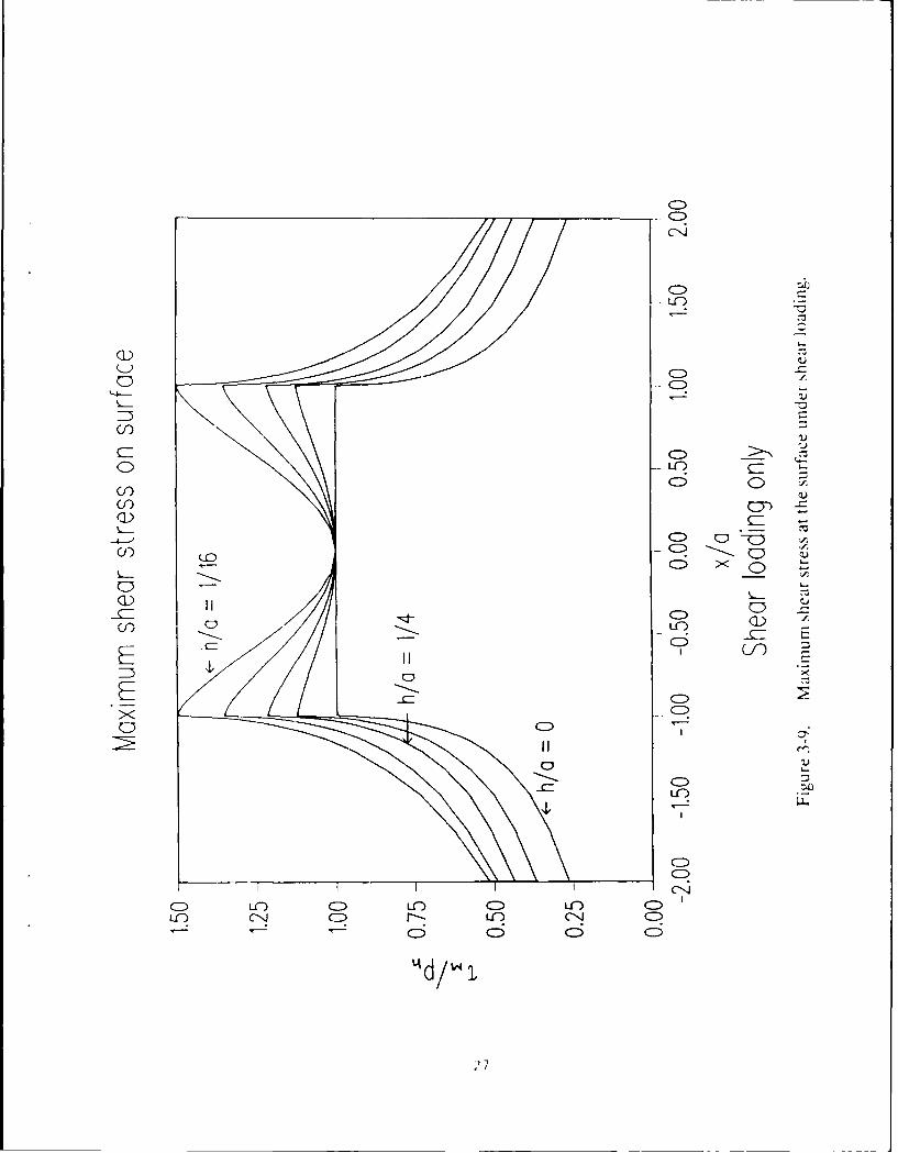
The influence of surface shear stress as a function of coating thickness is shown infigures 3-7 to 3-9. Figure 3-7 shows the variation in shear stress as a function of depth. As mightbe expected, the shear stress reduces with increasing depth. The surface shear stress acting inthe negative x direction produces compressive qx before the center of contact and a tensilestress after the center of contact (figure 3-8). The peak value of these stresses increases as thecoating thickness decreases to a limiting value equal to the product of stress with no coatingpresent and the coating to modulus ratio. Similarly, high values of the maximuml shear stressoccurs near the edge of contact, and it tends to increase towards a limiting value as the coatingthickness reduces, as seen in figure 3-9.
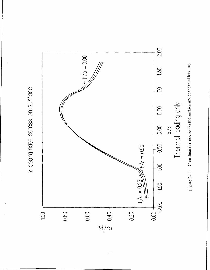
The surface temperature rise due to the applied thermal loading is shown in figure 3-10.The surface temperature climbs from the bulk temperature of the substrate at the start of thecontact zone to a peak value near the trailing edge of contact where it falls off rapidly as theheat is conducted away through the solid. The presence of surface convection would CaLlse thesurface temperature to fall off more rapidly beyond the contact zone but would not significantlyaffect its value within the contact. Due to the thermal loading onl.,, the variations of tie xcoordinate stress and the maxi mu iii shear stress are shown rcspectivcly in figures 3-11 and3-12. The behavior of these stresses tends to follow the general pattern of the temperaturedistribution. The v coordinate stress, ay, and the orthogonal shear stress, r-A., are both quitesmall.
2()
~CD
CDC
CN CD
G):
-4---' LC) -. 2
G):
LCD
21
CD
coD
C:))
0 L0
7CD
S.--
C_ L.C) C
IIn CN r-WE
6 6 C:
Id/
CD.
CD
- r- -
CiC:)
Cf) C) 0
0U)C/)-
C-C
E C
CIIj C5 C
4, -
L4-) CN- - C
23
LCC)
LC) .LC
C- CD
o IC)
ci)
CD >zCDD
I I I I CIC) CD
6n 6
2C"
C)
Cl
Cfi
C- LC)
CfC)
C)rC)
ICCDCC?
CDC)~L IC )I)c)
CD r--I) C14CD
CS 6
L'd
CNC-clr.
CDQ00
C)~ -=
Cr)CD
0
(f)).
CD
00 CNJ
0 0 00
X ) CN -CN
CN
-C)
g)r
0U
CJf) -E
C0 (Z
ci) -
-0 -)
Cf) 'CD
0< CD
C/ D Ln C nC i
0" 7
CD
CNJ
(I-) C
Ln C5ci) jCDL
(3))
~.4~~2
6:IID
00
0 6D
Uf) -CD
QL)-4-C)
CH-
00
I CD
CD ~ 00 CN C
-6 6;
'd/xYo
(~(Z)
'4-'
(I-))0 C)
C)0))
C())
6<-
0.C)
EE E3
X
Cf)
CDC ) DC C -Lc') rl- C- ) C63 6C6
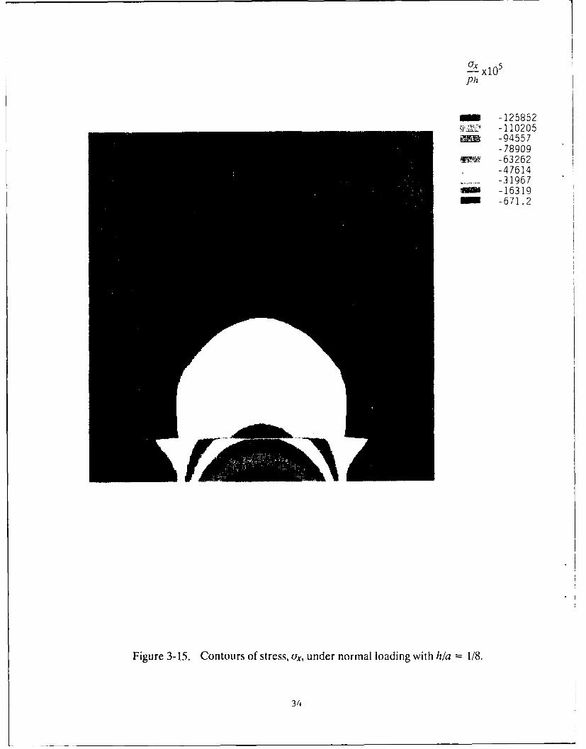
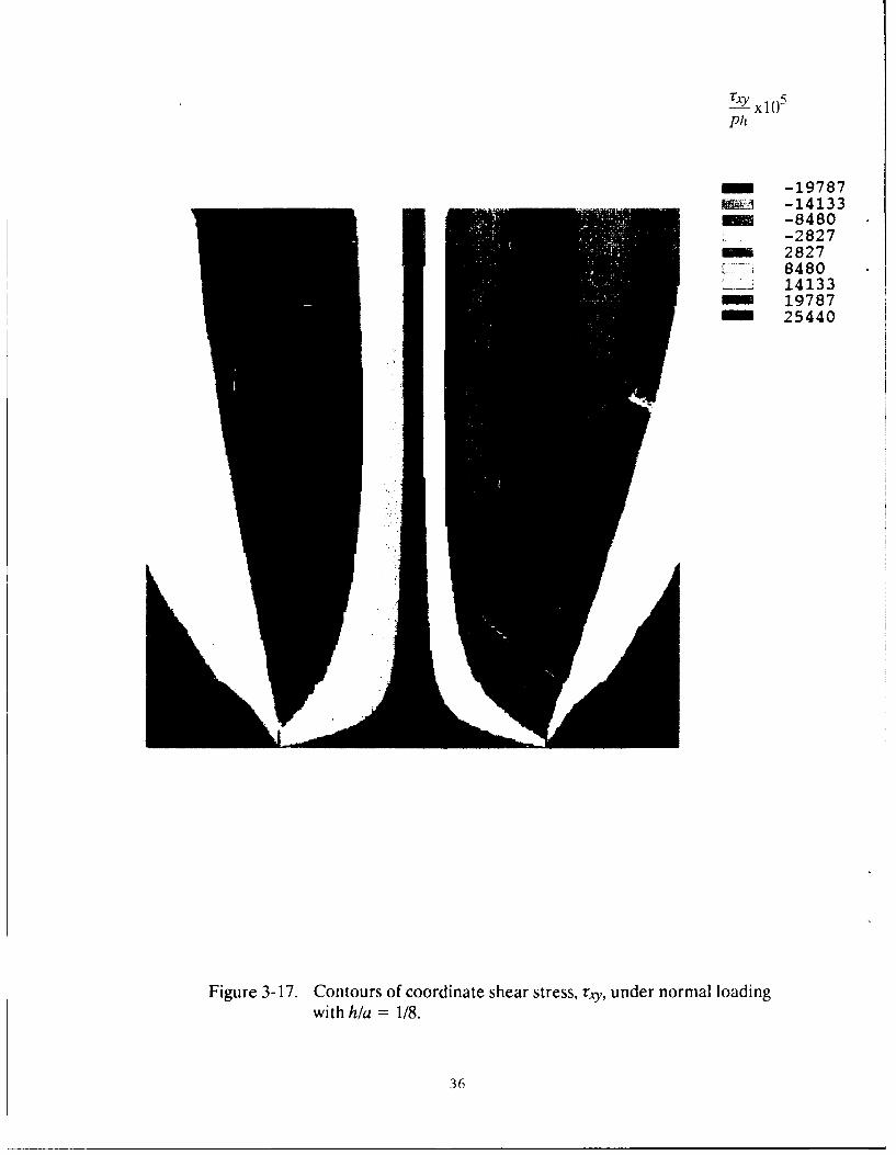
The finite element model provides detailed contour plots through the entire solid.Typical plots for the subsurface stresses and temperatures are shown in figures 3-13 to 3-21.The numerical values associated with each color shade are defined in the legend included withthe contour map. Each color shade in the contour map represents a stress (or temperature)value that is less than or equal to the value defined in the legend. The aspect ratios in theseplots have been distorted for clarity. The horizontal dimension of the plots spans four halfwidths along the surface. The three tic marks respectively correspond to the start, center andend of contact zone. The vertical dimension covers only one half width. Figures 3-13 and 3-14show respectively the normal and shear stress profiles for the Hertzian case. Note themaximum shear stress occurs at a certain depth (figure 3-14). This depth is generally used incomputation of fatigue life in rolling bearings where the material is subjected to cyclic loading.For a relatively thin coating, h/a = 1/8 the coordinate stress, Tx and the maximum shear stressrin are shown in figures 3-15 and 3-16 respectively. Note the discontinuity in stresses at tiecoating/substrate interface. The coordinate shear stress rxv, however, is, continuous across theinterface, as seen in figure 3-17.
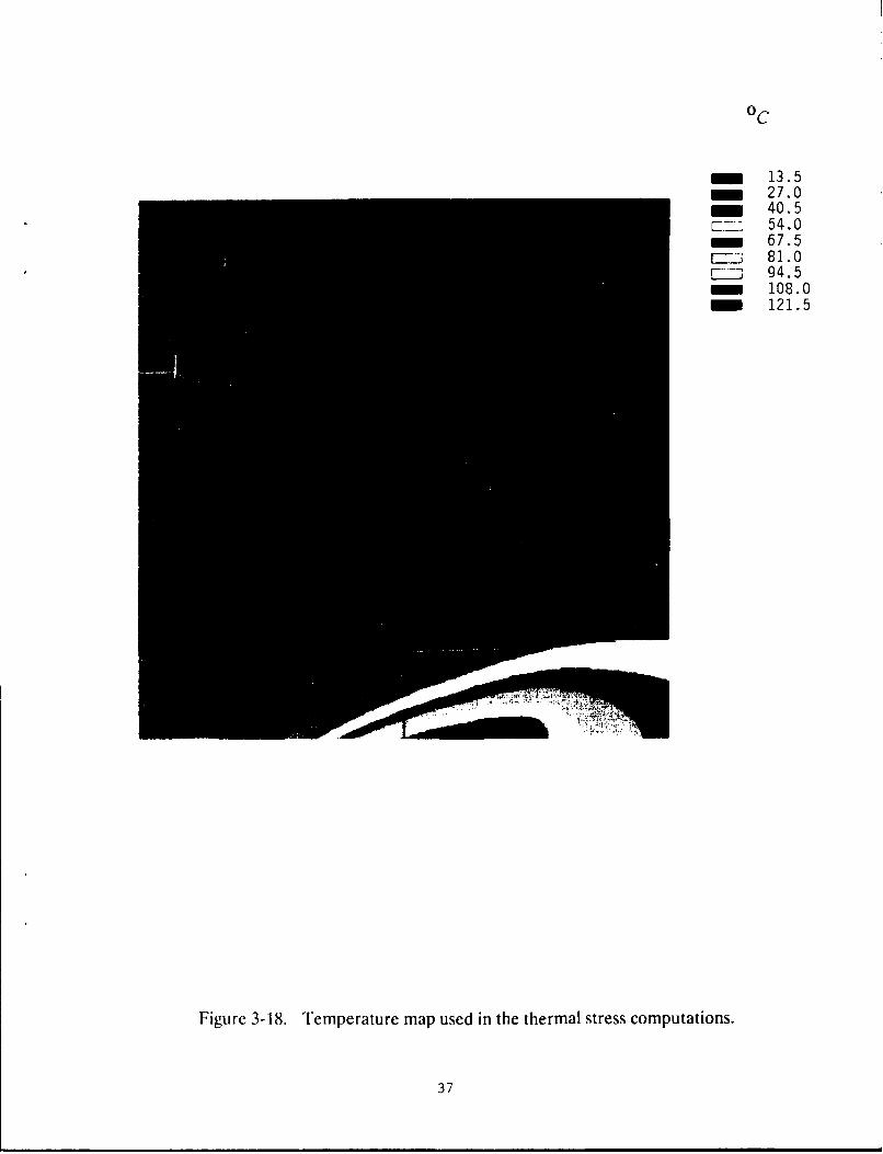
The temperature contours used in the thermal stress computations are shown in figure3-18. Note the thermal boundary layer behavior that occurs in a high-speed contact. For thepurpose of comparison, a second case of thermal loading is obtained by reducing both thePeclet Number (which represents a reduction in speed) and the thermal conductivity of thecoating by a factor of 2. The resulting temperature contours, as shown in figure 3-19, indicateboth an increased depth of propagation into the solid (due to reduced Peclet Number) andhigh values of the surface temperature (due to decreased thermal conductivity). The solutionsfor the coordinate stress, ix, corresponding to these two temperature distributions are shownin figures 3-20 and 3-21.
The above results clearly demonstrate the technical feasibility of the finite elementapproach. Since all stresses are scaled relative to the maximum applied pressure or shear stress,the solutions may be applied to any applied loading. Similarly, all linear dimensions are scaledrelative to the contact half width, thus the results may be applied to a wide range of coatingthicknesses. However, results are shown for only one value of the ratio of the elastic modulusof the coating to that of the substrate. Also, for the purpose of proving the technical feasibilityof the modeling approach, a simple two-dimensional line contact configuration is consideredabove. This permits validation of the finite element solutions with those obtained by othernumerical techniques. In general, however, the finite element modeling approach is applicableto any contact geometry. For effective practical application of the model, dimensionlesssolutions similar to the ones discussed above may be generated over a large range of geomet-rical and operational parameters to establish a design data base. This data base can then bereadily used to carry out design optimization for any given application.
To further establish the design significance of modeling approach, a series of rc,tilts,similar to the ones discussed above, are obtained by executing the computer program I AYFRl,.based on the Fourier transform approach. The results are applied to a 30 mm bore solid-lu-bricated hall bearing, operating at 70,000 rpn with a thrust load of 1,000 N and a rotating radialload of 50)0 N. The bearing dynamics analysis based oii the computer program AI)()RI" 1141reveals that for such an application typical values of contact stresses and half width assume
,i1
-lO
-87 904UI~-76799
in-65693-54588
r- 43 4 8 2----32377
_ -21271-10 166
rn940.0
Figure 3-13. Stress contours for ax under normal loading without a coating.
32
m x105
Ph
m 3425- 6804" 10184
13563- 16942
[ 20322L 23701
2708130460
Figure 3-14. Contours of maximum shear stress under normal loading with-out a coating.
33
-125852YJ -110205___ -94557
-78909~~t -63262
-47614-- -31967
-16319-671.2
Figure 3-15. Contours of stress, Lix, under normal loading with h/a 1/8.
34
Ti 1 0 5-- xlO 0p1:
- 4111poo 7910m 11709
1550919308
-L 23107.: 26906
3070634505
Figure 1 16 Contours of maximum shear stress under normal loading withh/a = 1/8.
35
TAy x105
Ph
m -19787A -14133- -8480
-282728278480141331978725440
Figure 3-17. Contours of coordinate shear stress, rxy, under normal loadingwith h/a = 1/8.
36
oC
m 13.5m 27.0- 40.5
E-II 54.0- 67.5
S81.0r .L2 94.5
108.0121.5
Figure 3-18. Temperature map used in the thermal stress computations.
37
oC
H - 17.835.6
- 53.4-- -- 71.2
89.0L 106.8
124.6S142.4
n 160.2
Figure 3-19. Temperature map under reduced Peclet number and increasedthermal conductivity of the coating.
38
Pit
m -492.0-427.8
WW- -363.6299.4
-~235.3171.1106.9
-42.721.4
FigUre 3-20. Contours of a under the temperature field of figure 3-18.
39
PIZ
-~-612.1-~-532.7
453.2373.8
;& -294.4214.9
- - 135 5- -56.0
23.4
Figure 3-2 1. Contours of (,x under the temperature field shown in figure 3-19 for reduced Peclet number.
40(
values of 10 9 Pa and 10- 5 M. When the dimensionless results obtained by executing theprogram LAYER are applied to this problem, pertinent stresses may be related to the appliedcoating thickness and therefore, practical guidance on the coating substrate design may beobtained. Typical results are shown in figure 3-22, where the maximum coordinate shear stress,which occurs close to the edge of the contact, is plotted as a function of coating thickncss .two different values of the elastic modulus of the coating. The coating surface is loaded withan elliptically distributed normal loading with a maximum pressure of 10)9 Pa. The substrate isassumed to be a bearing steel with a modulus of 2.0x10¹¹ Pa. The higher coating modulus isrepresentative of ceramic materials, while the lower modulus value simulates a relatively softcoating of some solid lubricant materials. The results show that the interfacial shear stressesfirst increase with increasing coating thickness, and beyond a certain value of the coatingthickness, the shear stress begins to drop. Thus some guidance on required "break-away" shearstress may be obtained. This may help determine the coating application techniques andprocedures.
In addition to the normal loading discussed above, the coating surface may be subjectedto a shear stress result from relative sliding due to ball slip or skid. In order to simulate sucha condition, additional solutions are obtained with an elliptically distributed shear stress. The
peak value of the shear stress is assumed to be 108 Pa, which ,oiicsponds to a frictioncoefficient of 0.10. As already discussed earlier with the finite element solutions, the shearstress at the surface induced tension at the coating/substrate interface. Again, the maximumtension occurs near the entrance to the contact zone. Typical results are shown in figure 3-23.Tension at the interface tends to reduce with increasing coating thickness for both the hardand soft coats.
The solutions of figures 3-22 and 3-23 may be superimposed to obtain a combined effectof liormai and shear ioadings on the coating surface. Thus failure under both tension andinterfacial shear may be modeled, and substantial guidance for the required break-awaystresses may be obtained.
Aside from the mechanical loading discussed above, the thermal loading, resulting fromthe heat generated at the coating surface, becomes important particularly when the thermalcoefficient of expansion of the coating is greatly different from that of the substrate. Forexample, the coefficient of thermal expansion for ceramic material, such as SiN, is 2.9x10 -
M/NI/"(, while that of N5() bearing steel is 12.3x1() - 6 M/M('C. Under such a thermalmismatch, the interfacial shear stresses may be greatly altered, and it is essential to revise thecoating/substrate adhesion or break-away stress requirements. Under the simplified assump-lions of the tenperature field, discussed earlier in section 2, figure 3-24 show, in increase inthe maximum orthogonal shear stress at the coating/substrate interface with the increasingtemperature rise in the contact for two different values of coating thickness. Once again, thesestresses may be linearly superimposed on those obtained with mechanical loading to derivethe required failure limits for the combined effects.
The above discussion illustrates application of the model resLIlts to an actual problem.
'it
2~, -
A x
'-, -
~ ~-C
- L.~
I
m
-. 4~I)
U 4
U.UrR _ __
xew(edS) xD
I' 3
400
A- x
/li-
xe w(edE8 I~l
Once again, it may be emphasized that for most design applications, it may not be necessaryto solve the integral problem, once a design data base of dimensionless solutions over a rangecovering the design parameters is available. In fact, after proving the technical feasibility ofthe modeling approach in the present Phase I, the generation of such a design data base shallbe undertaken in Phase Ii of this project. In addition to the two-dimensional problem,discussed above, the Phase II work scope shall include modeling of the more complicatedthree-dimensional problem. The following discussion of a preliminary three-dimensionalmodel provides added support for the finite element approach to modeling any contactgeometry.
3.3 Three-Dimensional Finite Element Modeling
Modeling of a three-dimensional contact greatly increases both the mass storage andcomputing speed requirements, which adds to the limitations of PC-ANSYS and the use ofpersonal computer systems for finite element modeling. However, for the purpose of feasibilitydemonstration, once again, PC-ANSYS is used to model a simple three-dimensional problem.The grid structure is kept relatively coarse, in order to make the finite element code workablewithin the storage limitations of the available personal computer system. A uniform pressureover a rectangular contact region is assumed on the coating surface. The element geometryand loading conditions are schematically shown in figure 3-25. The aspect ratio is somewhatdistorted but the complete grid is shown. The shaded area represents the load region. Thesurface boundaries are defined by x = ±5a and z = 5b with b/a = 2. The depth of the solidcorresponds toy = 5a. A symmetry condition inz direction is imposed by requiring zero normaldeflection at z=0. As in the two-dimensional model, discussed above, a zero deflectioncondition is imposed at they boundary of the solid, and remaining surfaces, with the exceptionof the contact zone, are assumed to free of any loads. The PC-ANSYS supplied three-dimen-sional isoparametric element having 8 nodes and 3 degrees of freedom at each node is used.All material properties are assumed to be identical to those used in the two-dimensionalmodeling.
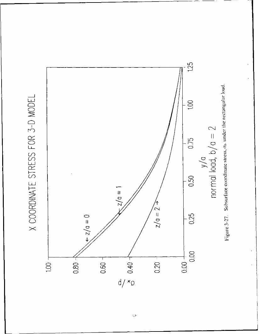
Solutions are first obtained without any coating. A consistency check on the solutionsis obtained by computing the surface loads and comparing them with the applied boundaryconditions. Figure 3-26 shows the results. The discrepancy in the finite element solutions isclear when the plotted solution is compared with a rectangle. Considering the rather coarsegrid used in generating this solution, this deviation is quite acceptable. Typical stress solutionsare shown in figure 3-27, where the variation in (ux with depth is plotted at various values ofzia in the y-z plane, defined byx=0.
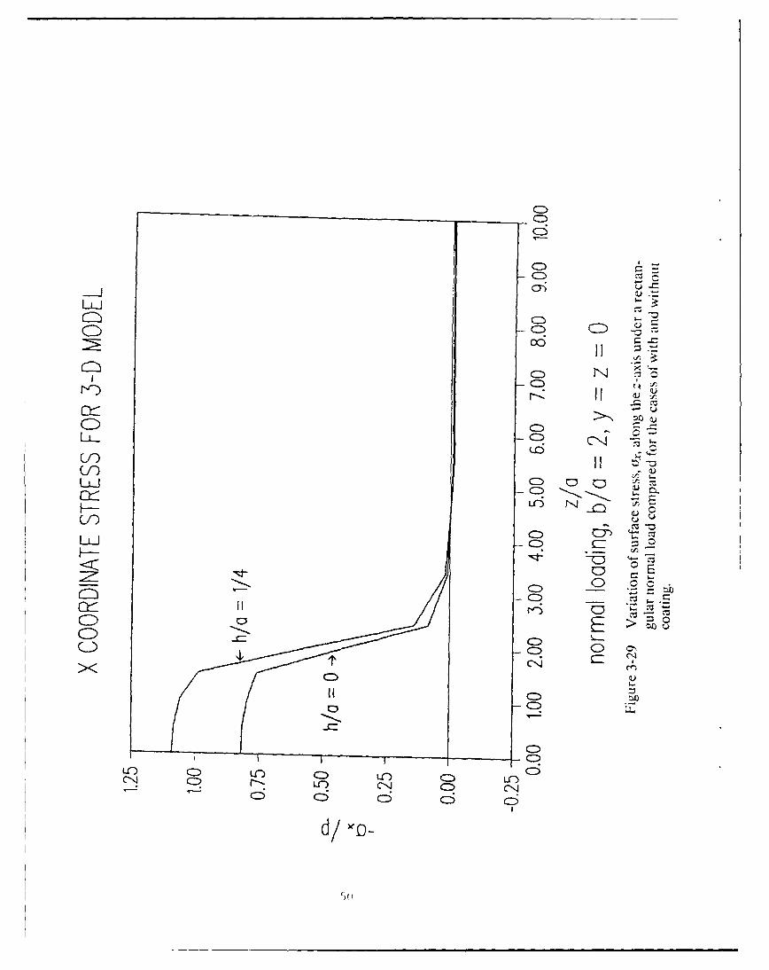
Similar to the above solutions, figures 3-28 and 3-29 show solutions with a coating ofthickness, h = 0.25a. The variation of computed stress ox along the x axis is shown in figure
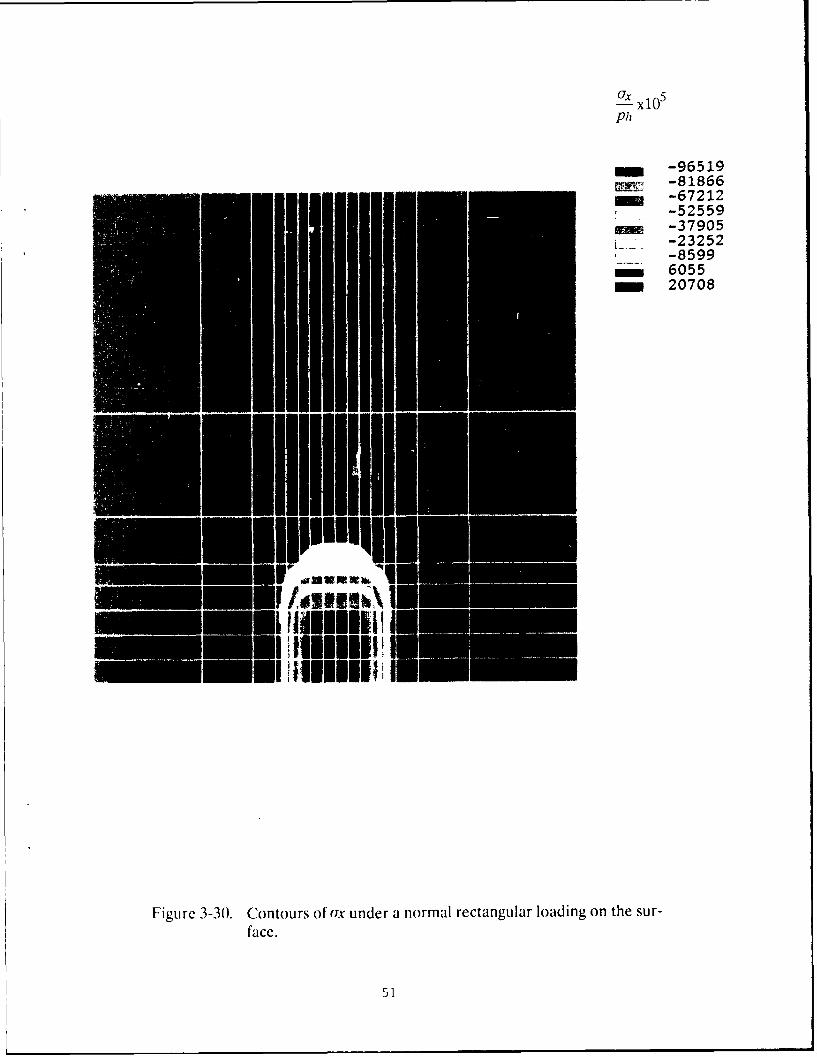
3-28 while the distribution along the z direction is plotted in figure 3-29. For comparison, thesolutions for the no coating case (h/a = 0) are also plotted. Again, the deviations from a truerectangle are quite acceptable in view of the coarse grid. A contour map of the surface loading,as shown in figure 3-30, further elaborates on the computed surface loading.
It ')
___
FigUre 3-25. Finite element grid structure on the surface for .1 three-dimen-sional miodel.
C)C
ME
CDD
EDC U)
cCD
ECDWC.
__C:)
6CD 0 O -4 CD c-
(J) Cd/I-
w I ~47
CLC
-1N
LU
NN
C)) CDCDC
c-/d/
LI:)
CV) CD,
cCDC-0-
Cf) CD C
-< E7
H- -CD
CD~
rlo
CD CD
Lnn
LC) CD C:) Ln C LC)CN CDLC CN- CD cN-
d/xo
/49
LLU
00
CD N
CD C:)
LC)
C).
F--
0 D
d/ no-
r)i ' .
Ux x105ph
m -96519-81866
l -67212-52559
- -37905-23252-8599
- 6055m 20708
-- EI u '"IIImumui imimmil; Im
Figure 3-30. Contours of ax under a normal rectangular loading on the sur-face.
51
The above solutions clearly demonstrate the strength of the finite element approach tomodeling a three-dimensional contact geometry. These solutions, when combined with thetwo-dimensional solutions and the validations against the solutions obtained by the Fouriertransform approach, and those predicted by the classical Hertz theory, prove the feasibility ofthe modeling approach to the design of coated solids.
52
4. SUMMARY
The personal computer based PC-ANSYS finite element code is used to develop afinite element approach to model stresses in coated solids is considered. A plane-strainproblem is first considered to prove technical feasibility of the approach. Parametric runs overseveral design parameters, such as coating thickness, materials properties and operatingconditions, demonstrate the practical significance of the model. Extension of the plane strainmodel to the more complicated three-dimensional contact is demonstrated by modeling arectangular contact area with uniform pressure. This preliminary three-dimensional model,along with the validated results of the two-dimensional model, clearly demonstrate thetechnical feasibility and practical design significance of the modeling approach. In addition,the preliminary models provide a strong technical foundation to develop more rigorous andsophisticated models for a wide range of practical applications.
The stress distributions in the coating and substrate are computed with the coatedsurface subjected to elliptically distributed normal and shear loadings under plane strainconditions. To model thermal loading, the temperature distribution in the entire solid,resulting from a prescribed heat flux on the coating surface, is first computed by a finitedifference analysis; the computed temperatures are then input to the finite element model andthe resulting thermal stresses are computed. In the absence of a coating, predictions of thefinite element model are shown to agree with the classical Hertzian theory with a maximumof 1% deviation. With the coating present, a well established Fourier transform approach isused to validate the predictions of the finite element model. Once again, the deviation of thestress distributions obtained by both these models is shown to be less than 1%.
With an elliptically distributed heat flux on the coating surface, the thermal stresses inthe entire solid are calculated to further establish the practical significance of the finiteelement model. In parallel, the Fourier transform approach is modified to permit an arbitrarydisplacement boundary condition at the coating/substrate interface to provide a preliminarymodel to simulate a thermal mismatch due to different thermal coefficient of expansion of thecoating and substrate materials. Parametric runs as a function of coating thickness, and appliedthermal and mechanical loadings demonstrate the practical significance of the models formaterials selection, coating thickness optimization, and selection of coating application tech-niques and procedures to permit acceptable limiting shear and "break-away" stress limits inthe coating and at the coating/substrate interface.
Validation of the three-dimensional model with a rectangular loading is tested by backcalculating the boundary loading and comparing it with the applied conditions. Such compar-isons are carried out both with and without a coating, and the results in both cases are quiteencouraging.
For a three-dimensional contact, relevant to geometrically complicated interactions,the mass stor:ge and computing speed requirements impose some restrictions on the use ofpersonal computer systems and a demand for a more advanced computer work station or amainframe computer system becomes clear. However, the results obtained with the PC-ANSYS system do prove technical feasibility of the overall approach and they provide a sound
53
analytical foundation for a more rigorous development in the future. In addition, the paramet-ric results have some immediate significance for practical design of coated solids subjected toconcentrated contact loads.
34
5. RECOMMENDATIONS FOR FUTURE DEVELOPMENT
Results of this Phase I investigation prove the technical feasibility and practicalsignificance of the overall analytical approach to modeling of stresses in coated solids. Thegood agreement between the finite element approach, the numerical integral formulations,and the classical Hertz type solutions establishes the predictive strengths of the models. Whilethe Fourier transform approach provides accurate numerical solutions to simplified contactconfigurations, the finite element models are applicable to arbitrary geometries, and theypermit modeling of fairly complex mechanical and thermal loading. In practice, the process ofmaterials selection and development consists of simple friction and wear tests where thecoatings are applied to simple specimens with well defined geometry. Once the materials areproven in such test, the coatings are applied to real components, such as bearings, gears, pistonrings or liners, and similar mechanical components. Thus it is essential to develop analyticalmodeling techniques for both simplified contact configurations and complicated contacts withcomplex geometries and loadings. Further advancement of both the numerical integral modelsand the finite element techniques is, therefore, essential. The following are some recommen-dations for further development.
1. The current plane strain integral model, and the computer program, LAYER, shouldbe extended to treat multiple coatings. This will be extremely useful in modeling compositesolids. Furthermore, by making the coating thickness small, an almost continued variation inproperties throagh the solid can be modeled.
2. The plane strain model should be extended to treat any prescribed temperature field.In fact, a thermal model, similar to the one discussed in this report, should be incorporated inthe plane strain integral model to automatically calculate the temperature field and theresulting thermal stresses in the solid.
3. The effort in the above two steps can be combined to model the effect of propertyvariation as a function of temperature. Thus the net effect of both the thermal stresses due tothe applied temperature field and the change in mechanical stresses due to altered fundamen-tal properties can be simultaneously determined. Aside from designers, such a model will bevaluable to be materials development scientists and chemists.
4. Experimental validation of analytical predictions is essential to enhance the designstrengths of the models. Some of the available failure data may be used to validate the modelfor predictions of interfacial tensile and shear stresses.
5. Modeling of elliptical contacts is another extension of the current plane strain model.This can be a rather complex task because the current Fourier transforms have to be replacedwith more complex Hankel transforms.
6. The finite element techniques can be easily advanced to model three-dimensionalcontacts. Perhaps, this approach may provide solutions to elliptical contacts fairly efficiently.It may be essential to develop these models on a main frame computer due to rather largemass storage and fast computing speed requirements.
55
7. For practical implementation of the finite element models, there are several areaswhich require development. Automatic mesh and load generators are essential for efficientproblem definition. The finite element packages, such as NASTRAN and ANSYS, require aninput data file, the preparation of which can become fairly tedious as the complexity of theproblem increases. It is, therefore, essential to develop a "pre-preprocessor" to efficientlyassemble the required input data files for the finite element models. Similarly, a "post-postprocessor" is sometimes essential to present the results in easily understandable engineer-ing terms.
8. Once a large number of validated solutions are obtained by both finite element andthe Fourier transform approaches, the results may be incorporated into a design data base.Basically, the results can be cataloged in terms of curve fits and systematic table lookups. Sucha data base can be easily implemented on a personal computer and it can be an efficient toolfor materials developers and practical designers.
9. In addition to the stress solutions, the practical significance of the above data basecan be significantly enhanced by including the available materials property data. Such anenhancement provides fairly quick and efficient assessment of break-away stresses and iden-tification of possible failures in a wide range of practical application.
10. The above design data base can also be interfaced with full finite element andnumerical integral solutions. This permits easy modeling of problems which are beyond thelimits of the data base.
REFERENCES
1. Aleksandrov, V. M., "On the Approximate Solution of a Certain Type of Integral
Equation", Prikladnaya Matematika y Mekhanika, vol 26, in English translation, pp 1410, 1962.
2. Aleksandrov, V. M., "Some Contact Problems of Elastic Layer", Prikladnaya
Maternatika y Mekhanika, vol 27, in English translation,pp 1164, 1963.
3. Aleksandrov, V. M., "Asymptotic Methods in Contact Problems in Elasticity Theory",
Prikladnaya Matematika y Mekhanika, vol 32, in English translation, pp 691, 1968.
4. Aleksandrov, V. M., "Asymptotic Solution of the Contact Problem for a Thin Elastic
Layer", Prikladnaya Matematika y Mekhanika, vol 33, in English translation, pp 49, 1969.
5. Meijers, P., "The Contact Problem of a Rigid Cylinder on an Elastic Layer", Applied
Scientific Research, vol 18, pp 353, 1968.
6. Wu, T. and Chiu, Y. P., "On the Contact Problem of Layered Elastic Solids", Quarterly
of Applied Mathematics, XXV, pp 233, 1967.
7. Pao, Y. C., Wu, T. and Chiu, Y. P., "Bounds on Maximum Contact Stress of an
Indented Elastic Layer", Journal of Applied Mechanics, vol 38, No. 3, Trans ASME, vol 93E,
pp 638, 1971.
8. Gupta, P. K. and Walowit, J. A., "Contact Stresses Between an Elastic Cylinder and
a Layered Elastic Solid', Journal of Lubrication Technology, ASME Trans, vol 96F, No. 2, pp
250, 1974.
9. Lemcoe, M. M., "Stresses in Layered Elastic Solids", Proc ASCE, EM4, pp 1, August
1960.
10. Barovich, D., Kingsley, S. C. and Ku, T. C., "Stresses on a Thin Strip or Slab with
)ifferent Elastic Properties From That of the Substrate Due to Elliptically Distributed Load",
International Journal of Engineering Sciences, vol 2, pp 253, 1964.
11. Ku, T. C., Kingsley, S. C. and Ramsey, H., "Stresses in a Thin Slab With Different
Elastic Properties From That of the Substrate Due to Distributed Normal and Shearing Forces
on the Surface of the Slab", International Journal of Engineering Sciences, vol 3, pp 93, 1905.
12. Gupta, P. K., Walowit, J. A. and Finkin, E. F., "Stress Distributions in Plane Strain
Layered Elastic Solids Subjected to Arbitrary Boundary Loading", Journal of Lubrication
Technology, ASME Trans, vol 95F, pp 427, 1973.
13. Gupta, P. K., LAYER - A Computer Code for Analysis of Plane-Strain Layered
Elastic Solids, PKG Inc, 1984.
57
14. Gupta, P.K., ADVANCED DYNAMICS OF ROLLING ELEMENT, Springer-Verlag, 1984.
58
APPENDIXThermal Analysis of Semi-infinite Solid with a Moving Heat Source
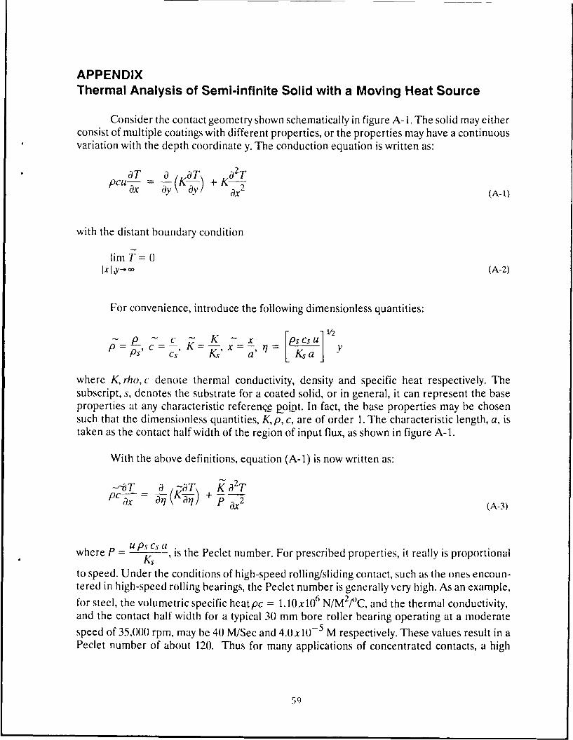
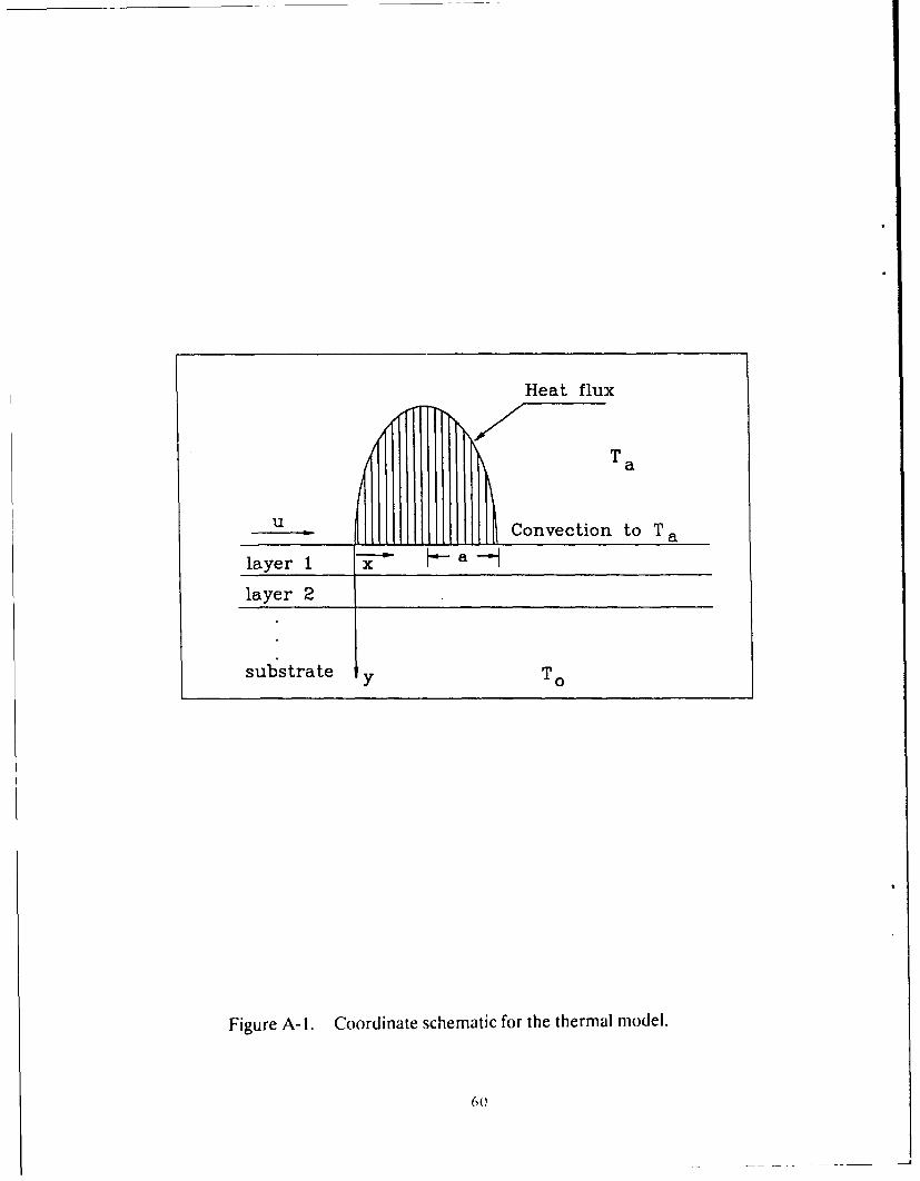
Consider the contact geometry shown schematically in figure A-1. The solid may eitherconsist of multiple coatings with different properties, or the properties may have a continuousvariation with the depth coordinate y. The conduction equation is written as:
aT a KT Ka 2Tcu ay + Ka 2 (A-1)
with the distant boundary condition
lim T = 0xIy- (A-2)
For convenience, introduce the following dimensionless quantities:
K V2- c K - x sCsUPs ,C Ks, a =/ [ya
where K, rho, c denote thermal conductivity, density and specific heat respectively. Thesubscript, s, denotes the substrate for a coated solid, or in general, it can represent the baseproperties at any characteristic reference p-oint. In fact, the base properties may be chosensuch that the dimensionless quantities, Kp, c, are of order 1. The characteristic length, a, istaken as the contact half width of the region of input flux, as shown in figure A-1.
With the above definitions, equation (A-I) is now written as:
--i) T a -aT Ka2 TPCx-
C) q +P ax 2 (A-3)
whereP - ps cs awhere P = u , is the Peclet number. For prescribed properties, it really is proportional
to speed. Under the conditions of high-speed rolling/sliding contact, such as the ones encoun-tered in high-speed rolling bearings, the Peclet number is generally very high. As an example,for steel, the volumetric specific heatpc = 1.10x10 6 N/M 2/ C, and the thermal conductivity,and the contact half width for a typical 30 mm bore roller bearing operating at a moderate
speed of 35,000 rpm, may be 40 M/Sec and 4.0x10 - 5 M respectively. These values result in aPeclet number of about 120. Thus for many applications of concentrated contacts, a high
59)
Heat flux
Ta
u . Convection to Ta
layer 1 -x h-a-
layer 2
substrate y To
Figure A-I. Coordinate schematic for the thermal model.
6()
Peclet number approximation is quite reasonable. Thus, the last term in equation (A-3) maybe dropped and the conduction equation may be written as:
- -- T _ ~ 8 -TPP x av \ Xv/'xy > 0P- (A-4)
with the boundary conditions
T= 0 atx=O, and lim T= 0y--. 0 (A-5)
wherey = y/a, a being the half width of contact.
If qo is the amplitude of input flux, the flux distribution in the contact may be writtenas
q = qof(X) (A-6)
and the surface input flux condition is written as
-K-T=f(x), aty=OandOx20y (A-7)
T qo
where T = , with Tr = as a reference temperature.
The convective heat transfer condition is
-K-= HI(T- Ta), aty=Oandx>2Oy (A-8)
Ta - hai.where Ta is the dimensionless ambient temperature -r and H is the Nusselt number
with a heat transfer coefficient h.
For most concentrated contacts it may be reasonable to assume that the heat flux isproportional to the contact pressure. Thus the heat flux function in equation (A-6) may bewritten as
61
f(x) (x1)2]t, 0!5x<2 (A-9)
For any aroitrary variation in properties, the above equations are best solved numeri-cally by finite differe.nce .pproximations. A grid structure, shown schematically in figure A-2,is chosen starting atx = v= 0. For brevity, the is dropped in all the following formulation fornumerical analysis.
For performing heat flow balance over the dotted rectangle, as shown in figure A-2,the heat flow out of the rectangular across the surface c is written as
and the heat flow out of the rectangle across surface b is written as
P I pi-lci-i Tj+i,-I + I T+tiAyi]
In the above expressions Axj -x j+1 - xj and Ayi = yi+1 - yi; and, the properties,K, Pi, ci prevail in the interval yi<_y<_yi+ 1.
Using the above relations, the flow across all four sides of the rectangle may be writtenand the sum may be equated to zero to derive the following equation:
P (Tj - Ti+ ij) (pi- ici-i Ayi- + pci Ayi) +
Ki ( Tj,+i - Tj + Tj+I,i+I - T+I)-I -
Ki-1 ( Tjj - Tj-1 + Tj+,i- Tj+I,i-1 ) 1 xi = 0Ayi- I (A-10)
The above equation applies to the interior points defined byj> 1, 1 <i<m, where m isthe total number of points in they direction. Also, the boundary condition aty= 00 is appliedat y =y.
The boundary conditions at x=0 and aty=yn result in the following boundary values
Ttj = 0 and ij),, = 0 (A-I)
Similar heat flow balances may be obtained over the "half' rectangles bounding thesurface with flux inputs corresponding to equations (A-7) and (A-8). The resulting equation
62
A1 2 4
a
Figuire A-2. Numecrical grid structure for the finite difference computation.
Equations (A- 10) to (A-12) when used to solve for Tj+i j represent a modified Crank-Nicholsen approach which is generally stable and provides quadratic accuracy. The equationsfor any column] may be written in the form
(i Tj,i + Di Tj.i+ + Vi ">-,i = Ri (A-13)
where Ri depends on J- i, which is obtained from equation (A- I ) forj= I and the previous
solution to equation (A- 13) forj> 1. The remaining coefficients are independent of tempera-ture.
If we look for a solution in the form
1, -1I = A4i 7. + 1i (A-14)
then by substituting 7i- in equation (A-13) and solving for 1j,i we obtain
i= i I5.+I + Bi+ I (A-15)
where
Di
Ci + 1i/4i (A-t1)
and .
Ni - 1-i BiB i+ j =. .. ... .Ci + F 'I (A- 17)
Since the temperatuires start at i= l we can take Ai =BI = (), then use equations (A- 16)and (A-17) to calculate all A and B values up to,,t,l ain] Bm. From equation (A-I 1) 7>,, = 0,
hence, equation (A-14) may be used to calculate the remaining temperatures from T,,-1 toT),i. The procedure is then repeated for the next column until the required temperature mapis obtained.
The above method of solution for the temperatures in a given column implements aRiccati transformation which provides good numerical accuracy even for relatively long spansin they coordinate.
In the event the properties are assumed to be constant and the convection term isneglected, the solution may be written in terms of an integral. This is accomplished bysubstituting K = p = c = I and H = 0 and by solving equations (A-4) to (A-7) by Laplacetransforms. The temperature distribution as a function of the input flux is written as
- 1 f x (x'
o (x-x)v2 (A-18)
The above relation may be readily used to check out the numerical results whenimplementing the above general procedure in a computer code. Also, the above relationsuggests using an effective temperature
= Tr
as a characteristic dimensional parameter for temperatures.