386
2550 Garcia Avenue Mountain View, CA 94043 U.S.A. Writing Device Drivers A Sun Microsystems, Inc. Business

2550 Garcia AvenueMountain View, CA 94043U.S.A.
Writing Device Drivers
A Sun Microsystems, Inc. Business

PleaseRecycle
1994 Sun Microsystems, Inc.2550 Garcia Avenue, Mountain View, California 94043-1100 U.S.A.
All rights reserved. This product and related documentation are protected by copyright and distributed under licensesrestricting its use, copying, distribution, and decompilation. No part of this product or related documentation may bereproduced in any form by any means without prior written authorization of Sun and its licensors, if any.
Portions of this product may be derived from the UNIX® and Berkeley 4.3 BSD systems, licensed from UNIX SystemLaboratories, Inc., a wholly owned subsidiary of Novell, Inc., and the University of California, respectively. Third-party fontsoftware in this product is protected by copyright and licensed from Sun’s font suppliers.
RESTRICTED RIGHTS LEGEND: Use, duplication, or disclosure by the United States Government is subject to the restrictionsset forth in DFARS 252.227-7013 (c)(1)(ii) and FAR 52.227-19.
The product described in this manual may be protected by one or more U.S. patents, foreign patents, or pending applications.
TRADEMARKSSun, the Sun logo, Sun Microsystems, Sun Microsystems Computer Corporation, SunSoft, the SunSoft logo, Solaris, SunOS,OpenWindows, DeskSet, ONC, ONC+, and NFS are trademarks or registered trademarks of Sun Microsystems, Inc. in the U.S.and certain other countries. UNIX is a registered trademark of Novell, Inc., in the United States and other countries; X/OpenCompany, Ltd., is the exclusive licensor of such trademark. OPEN LOOK® is a registered trademark of Novell, Inc. PostScriptand Display PostScript are trademarks of Adobe Systems, Inc. All other product names mentioned herein are the trademarksof their respective owners.
All SPARC trademarks, including the SCD Compliant Logo, are trademarks or registered trademarks of SPARC International,Inc. SPARCstation, SPARCserver, SPARCengine, SPARCstorage, SPARCware, SPARCcenter, SPARCclassic, SPARCcluster,SPARCdesign, SPARC811, SPARCprinter, UltraSPARC, microSPARC, SPARCworks, and SPARCompiler are licensedexclusively to Sun Microsystems, Inc. Products bearing SPARC trademarks are based upon an architecture developed by SunMicrosystems, Inc.
The OPEN LOOK and Sun™ Graphical User Interfaces were developed by Sun Microsystems, Inc. for its users and licensees.Sun acknowledges the pioneering efforts of Xerox in researching and developing the concept of visual or graphical userinterfaces for the computer industry. Sun holds a non-exclusive license from Xerox to the Xerox Graphical User Interface,which license also covers Sun’s licensees who implement OPEN LOOK GUIs and otherwise comply with Sun’s written licenseagreements.
X Window System is a product of the Massachusetts Institute of Technology.
THIS PUBLICATION IS PROVIDED “AS IS” WITHOUT WARRANTY OF ANY KIND, EITHER EXPRESS OR IMPLIED,INCLUDING, BUT NOT LIMITED TO, THE IMPLIED WARRANTIES OF MERCHANTABILITY, FITNESS FOR APARTICULAR PURPOSE, OR NON-INFRINGEMENT.
THIS PUBLICATION COULD INCLUDE TECHNICAL INACCURACIES OR TYPOGRAPHICAL ERRORS. CHANGES AREPERIODICALLY ADDED TO THE INFORMATION HEREIN; THESE CHANGES WILL BE INCORPORATED IN NEWEDITIONS OF THE PUBLICATION. SUN MICROSYSTEMS, INC. MAY MAKE IMPROVEMENTS AND/OR CHANGES INTHE PRODUCT(S) AND/OR THE PROGRAM(S) DESCRIBED IN THIS PUBLICATION AT ANY TIME.

iii
Contents
1. Overview of the SunOS Kernel . . . . . . . . . . . . . . . . . . . . . . . . . 1
What is the Kernel? . . . . . . . . . . . . . . . . . . . . . . . . . . . . . . . . . . . . 1
Multithreading . . . . . . . . . . . . . . . . . . . . . . . . . . . . . . . . . . . . . . . . 2
Virtual Memory . . . . . . . . . . . . . . . . . . . . . . . . . . . . . . . . . . . . . . . 2
Virtual Addresses . . . . . . . . . . . . . . . . . . . . . . . . . . . . . . . . . . 2
Address Spaces . . . . . . . . . . . . . . . . . . . . . . . . . . . . . . . . . . . . 2
Special Files . . . . . . . . . . . . . . . . . . . . . . . . . . . . . . . . . . . . . . . . . . 3
Dynamic Loading of Kernel Modules . . . . . . . . . . . . . . . . . . . . . 3
Overview of the Solaris 2.x DDI/DKI . . . . . . . . . . . . . . . . . . . . . 3
Device Tree . . . . . . . . . . . . . . . . . . . . . . . . . . . . . . . . . . . . . . . . 5
Example Device Tree . . . . . . . . . . . . . . . . . . . . . . . . . . . . . . . . 6
2. Hardware Overview . . . . . . . . . . . . . . . . . . . . . . . . . . . . . . . . . . . 9
SPARC Processor Issues . . . . . . . . . . . . . . . . . . . . . . . . . . . . . . . . 9
Data Alignment . . . . . . . . . . . . . . . . . . . . . . . . . . . . . . . . . . . . 9
Structure Member Alignment . . . . . . . . . . . . . . . . . . . . . . . . 10

iv Writing Device Drivers—August, 1994
Byte Ordering. . . . . . . . . . . . . . . . . . . . . . . . . . . . . . . . . . . . . . 10
Register Windows . . . . . . . . . . . . . . . . . . . . . . . . . . . . . . . . . . 10
Floating Point Operations. . . . . . . . . . . . . . . . . . . . . . . . . . . . 11
Multiply and Divide Instructions . . . . . . . . . . . . . . . . . . . . . 11
SPARC Architecture Manual . . . . . . . . . . . . . . . . . . . . . . . . . 11
x86 Processor Issues. . . . . . . . . . . . . . . . . . . . . . . . . . . . . . . . . . . . 11
Data Alignment . . . . . . . . . . . . . . . . . . . . . . . . . . . . . . . . . . . . 11
Structure Member Alignment . . . . . . . . . . . . . . . . . . . . . . . . 11
Byte Ordering. . . . . . . . . . . . . . . . . . . . . . . . . . . . . . . . . . . . . . 12
Floating Point Operations. . . . . . . . . . . . . . . . . . . . . . . . . . . . 12
x86 Architecture Manuals . . . . . . . . . . . . . . . . . . . . . . . . . . . . 12
System Memory Model . . . . . . . . . . . . . . . . . . . . . . . . . . . . . . . . . 12
Store Buffers . . . . . . . . . . . . . . . . . . . . . . . . . . . . . . . . . . . . . . . 12
SPARC Memory Model . . . . . . . . . . . . . . . . . . . . . . . . . . . . . . . . . 13
Bus Architectures . . . . . . . . . . . . . . . . . . . . . . . . . . . . . . . . . . . . . . 14
Device Identification . . . . . . . . . . . . . . . . . . . . . . . . . . . . . . . . 14
Device Addressing. . . . . . . . . . . . . . . . . . . . . . . . . . . . . . . . . . 15
Interrupts . . . . . . . . . . . . . . . . . . . . . . . . . . . . . . . . . . . . . . . . . 15
Bus Specifics . . . . . . . . . . . . . . . . . . . . . . . . . . . . . . . . . . . . . . . . . . 16
SBus . . . . . . . . . . . . . . . . . . . . . . . . . . . . . . . . . . . . . . . . . . . . . . 16
VMEbus . . . . . . . . . . . . . . . . . . . . . . . . . . . . . . . . . . . . . . . . . . 18
x86 Buses. . . . . . . . . . . . . . . . . . . . . . . . . . . . . . . . . . . . . . . . . . 21
MCA Bus. . . . . . . . . . . . . . . . . . . . . . . . . . . . . . . . . . . . . . . . . . 24
Device Issues . . . . . . . . . . . . . . . . . . . . . . . . . . . . . . . . . . . . . . . . . 24

v
Timing-Critical Sections . . . . . . . . . . . . . . . . . . . . . . . . . . . . . 24
Delays . . . . . . . . . . . . . . . . . . . . . . . . . . . . . . . . . . . . . . . . . . . . 25
Internal Sequencing Logic . . . . . . . . . . . . . . . . . . . . . . . . . . . 25
Interrupt Issues . . . . . . . . . . . . . . . . . . . . . . . . . . . . . . . . . . . . 25
Byte Ordering. . . . . . . . . . . . . . . . . . . . . . . . . . . . . . . . . . . . . . 26
The PROM on SPARC Machines . . . . . . . . . . . . . . . . . . . . . . . . . 26
Open Boot PROM 2.x . . . . . . . . . . . . . . . . . . . . . . . . . . . . . . . 27
Reading and Writing . . . . . . . . . . . . . . . . . . . . . . . . . . . . . . . . . . . 32
The Sun Monitor . . . . . . . . . . . . . . . . . . . . . . . . . . . . . . . . . . . 34
3. Overview of SunOS Device Drivers . . . . . . . . . . . . . . . . . . . . . 41
What is a Device Driver?. . . . . . . . . . . . . . . . . . . . . . . . . . . . . . . . 41
Types of Device Drivers . . . . . . . . . . . . . . . . . . . . . . . . . . . . . . . . 42
Block Device Drivers . . . . . . . . . . . . . . . . . . . . . . . . . . . . . . . . 42
Standard Character Device Drivers. . . . . . . . . . . . . . . . . . . . 42
STREAMS Drivers . . . . . . . . . . . . . . . . . . . . . . . . . . . . . . . . . . 44
Device Issues . . . . . . . . . . . . . . . . . . . . . . . . . . . . . . . . . . . . . . . . . 44
Accessing Device Registers . . . . . . . . . . . . . . . . . . . . . . . . . . 44
Example Device Registers. . . . . . . . . . . . . . . . . . . . . . . . . . . . 45
Device Register Structure . . . . . . . . . . . . . . . . . . . . . . . . . . . . 46
Driver Interfaces . . . . . . . . . . . . . . . . . . . . . . . . . . . . . . . . . . . . . . 48
Entry Points . . . . . . . . . . . . . . . . . . . . . . . . . . . . . . . . . . . . . . . 48
Callback functions . . . . . . . . . . . . . . . . . . . . . . . . . . . . . . . . . . . . . 51
Interrupt Handling . . . . . . . . . . . . . . . . . . . . . . . . . . . . . . . . . . . . 52
Driver Context . . . . . . . . . . . . . . . . . . . . . . . . . . . . . . . . . . . . . . . . 52

vi Writing Device Drivers—August, 1994
Printing Messages . . . . . . . . . . . . . . . . . . . . . . . . . . . . . . . . . . . . . 53
Dynamic Memory Allocation . . . . . . . . . . . . . . . . . . . . . . . . . . . . 54
Software State Management . . . . . . . . . . . . . . . . . . . . . . . . . . . . . 55
State Structure . . . . . . . . . . . . . . . . . . . . . . . . . . . . . . . . . . . . . 55
State Management Routines. . . . . . . . . . . . . . . . . . . . . . . . . . 56
Properties . . . . . . . . . . . . . . . . . . . . . . . . . . . . . . . . . . . . . . . . . . . . 57
Driver Layout . . . . . . . . . . . . . . . . . . . . . . . . . . . . . . . . . . . . . . . . . 60
Header Files . . . . . . . . . . . . . . . . . . . . . . . . . . . . . . . . . . . . . . . 60
The C Language and Compiler Modes . . . . . . . . . . . . . . . . . . . . 65
Compiler Modes . . . . . . . . . . . . . . . . . . . . . . . . . . . . . . . . . . . 66
Function Prototypes . . . . . . . . . . . . . . . . . . . . . . . . . . . . . . . . 66
New Keywords . . . . . . . . . . . . . . . . . . . . . . . . . . . . . . . . . . . . 66
4. Multithreading . . . . . . . . . . . . . . . . . . . . . . . . . . . . . . . . . . . . . . . 71
Threads . . . . . . . . . . . . . . . . . . . . . . . . . . . . . . . . . . . . . . . . . . . . . . 71
User Threads . . . . . . . . . . . . . . . . . . . . . . . . . . . . . . . . . . . . . . 71
Kernel Threads . . . . . . . . . . . . . . . . . . . . . . . . . . . . . . . . . . . . . 72
Multiprocessing Changes Since SunOS 4.x. . . . . . . . . . . . . . . . . 73
Locking Primitives. . . . . . . . . . . . . . . . . . . . . . . . . . . . . . . . . . . . . 74
Storage Classes of Driver Data. . . . . . . . . . . . . . . . . . . . . . . . 74
State Structure . . . . . . . . . . . . . . . . . . . . . . . . . . . . . . . . . . . . . 75
Mutual-Exclusion Locks . . . . . . . . . . . . . . . . . . . . . . . . . . . . . 75
Readers/Writer Locks . . . . . . . . . . . . . . . . . . . . . . . . . . . . . . . 77
Semaphores . . . . . . . . . . . . . . . . . . . . . . . . . . . . . . . . . . . . . . . 77
Thread Synchronization . . . . . . . . . . . . . . . . . . . . . . . . . . . . . . . . 77

vii
Condition Variables . . . . . . . . . . . . . . . . . . . . . . . . . . . . . . . . . 77
cv_timedwait( ) . . . . . . . . . . . . . . . . . . . . . . . . . . . . . . . . . 81
cv_wait_sig( ) . . . . . . . . . . . . . . . . . . . . . . . . . . . . . . . . . . 82
cv_timedwait_sig( ) . . . . . . . . . . . . . . . . . . . . . . . . . . . . 82
Choosing a Locking Scheme. . . . . . . . . . . . . . . . . . . . . . . . . . . . . 83
5. Autoconfiguration. . . . . . . . . . . . . . . . . . . . . . . . . . . . . . . . . . . . . 85
Overview. . . . . . . . . . . . . . . . . . . . . . . . . . . . . . . . . . . . . . . . . . . . . 85
State Structure . . . . . . . . . . . . . . . . . . . . . . . . . . . . . . . . . . . . . . . . 85
Data Structures. . . . . . . . . . . . . . . . . . . . . . . . . . . . . . . . . . . . . . . . 86
modlinkag e() . . . . . . . . . . . . . . . . . . . . . . . . . . . . . . . . . . . . . 87
modldrv() . . . . . . . . . . . . . . . . . . . . . . . . . . . . . . . . . . . . . . . . 87
dev_ops() . . . . . . . . . . . . . . . . . . . . . . . . . . . . . . . . . . . . . . . . 87
cb_ops . . . . . . . . . . . . . . . . . . . . . . . . . . . . . . . . . . . . . . . . . . . 88
Loadable Driver Interface. . . . . . . . . . . . . . . . . . . . . . . . . . . . 89
Device Configuration . . . . . . . . . . . . . . . . . . . . . . . . . . . . . . . . . . 91
identify( ) . . . . . . . . . . . . . . . . . . . . . . . . . . . . . . . . . . . . . 91
probe( ) . . . . . . . . . . . . . . . . . . . . . . . . . . . . . . . . . . . . . . . . . 93
attach( ) . . . . . . . . . . . . . . . . . . . . . . . . . . . . . . . . . . . . . . . . 95
detach( ) . . . . . . . . . . . . . . . . . . . . . . . . . . . . . . . . . . . . . . . . 100
getinf o( ) . . . . . . . . . . . . . . . . . . . . . . . . . . . . . . . . . . . . . . . . 102
6. Interrupt Handlers . . . . . . . . . . . . . . . . . . . . . . . . . . . . . . . . . . . . 105
Overview. . . . . . . . . . . . . . . . . . . . . . . . . . . . . . . . . . . . . . . . . . . . . 105
Interrupt Specification. . . . . . . . . . . . . . . . . . . . . . . . . . . . . . . 106
Interrupt Number . . . . . . . . . . . . . . . . . . . . . . . . . . . . . . . . . . 106

viii Writing Device Drivers—August, 1994
Bus-Interrupt Levels . . . . . . . . . . . . . . . . . . . . . . . . . . . . . . . . 106
High-Level Interrupts . . . . . . . . . . . . . . . . . . . . . . . . . . . . . . . 107
Types of Interrupts. . . . . . . . . . . . . . . . . . . . . . . . . . . . . . . . . . . . . 107
Vectored Interrupts . . . . . . . . . . . . . . . . . . . . . . . . . . . . . . . . . 107
Polled Interrupts . . . . . . . . . . . . . . . . . . . . . . . . . . . . . . . . . . . 108
Software Interrupts . . . . . . . . . . . . . . . . . . . . . . . . . . . . . . . . . 108
Registering Interrupts . . . . . . . . . . . . . . . . . . . . . . . . . . . . . . . . . . 109
Responsibilities of an Interrupt Handler . . . . . . . . . . . . . . . . . . 111
State Structure . . . . . . . . . . . . . . . . . . . . . . . . . . . . . . . . . . . . . . . . 113
Handling High-Level Interrupts . . . . . . . . . . . . . . . . . . . . . . . . . 113
Example . . . . . . . . . . . . . . . . . . . . . . . . . . . . . . . . . . . . . . . . . . 114
7. DMA . . . . . . . . . . . . . . . . . . . . . . . . . . . . . . . . . . . . . . . . . . . . . . . . 119
The DMA Model . . . . . . . . . . . . . . . . . . . . . . . . . . . . . . . . . . . . . . 119
Types of Device DMA . . . . . . . . . . . . . . . . . . . . . . . . . . . . . . . . . . 122
DMA and DVMA. . . . . . . . . . . . . . . . . . . . . . . . . . . . . . . . . . . . . . 122
Handles, Windows, Segments and Cookies . . . . . . . . . . . . . . . . 123
DMA Operations . . . . . . . . . . . . . . . . . . . . . . . . . . . . . . . . . . . . . . 124
Device limitations . . . . . . . . . . . . . . . . . . . . . . . . . . . . . . . . . . 126
Object Locking . . . . . . . . . . . . . . . . . . . . . . . . . . . . . . . . . . . . . 131
Allocating DMA Resources . . . . . . . . . . . . . . . . . . . . . . . . . . 131
Burst Sizes. . . . . . . . . . . . . . . . . . . . . . . . . . . . . . . . . . . . . . . . . 135
Programming the DMA Engine . . . . . . . . . . . . . . . . . . . . . . . 136
Freeing the DMA Resources . . . . . . . . . . . . . . . . . . . . . . . . . . 137
Cancelling DMA Callbacks. . . . . . . . . . . . . . . . . . . . . . . . . . . . . . 138

ix
Synchronizing Memory Objects . . . . . . . . . . . . . . . . . . . . . . . . . . 140
Cache . . . . . . . . . . . . . . . . . . . . . . . . . . . . . . . . . . . . . . . . . . . . . 140
ddi_dma_sync( ) . . . . . . . . . . . . . . . . . . . . . . . . . . . . . . . . . 142
Allocating Private DMA Buffers . . . . . . . . . . . . . . . . . . . . . . . . . 143
ddi_iopb_alloc() . . . . . . . . . . . . . . . . . . . . . . . . . . . . . . . . 143
ddi_mem_alloc( ) . . . . . . . . . . . . . . . . . . . . . . . . . . . . . . . . 144
ddi_dma_devalign( ) . . . . . . . . . . . . . . . . . . . . . . . . . . . . 145
8. Drivers for Character Devices. . . . . . . . . . . . . . . . . . . . . . . . . . . 147
Entry Points . . . . . . . . . . . . . . . . . . . . . . . . . . . . . . . . . . . . . . . . . . 147
Autoconfiguration . . . . . . . . . . . . . . . . . . . . . . . . . . . . . . . . . . . . . 148
Controlling Device Access . . . . . . . . . . . . . . . . . . . . . . . . . . . . . . 149
I/O Request Handling . . . . . . . . . . . . . . . . . . . . . . . . . . . . . . . . . 151
User Addresses . . . . . . . . . . . . . . . . . . . . . . . . . . . . . . . . . . . . 151
Vectored I/O. . . . . . . . . . . . . . . . . . . . . . . . . . . . . . . . . . . . . . . 152
Driver Operations . . . . . . . . . . . . . . . . . . . . . . . . . . . . . . . . . . 154
Mapping Device Memory . . . . . . . . . . . . . . . . . . . . . . . . . . . . . . . 159
Multiplexing I/O on File Descriptors . . . . . . . . . . . . . . . . . . . . . 162
Miscellaneous I/O Control . . . . . . . . . . . . . . . . . . . . . . . . . . . . . . 165
9. Drivers for Block Devices . . . . . . . . . . . . . . . . . . . . . . . . . . . . . . 169
File I/O . . . . . . . . . . . . . . . . . . . . . . . . . . . . . . . . . . . . . . . . . . . . . . 169
State Structure . . . . . . . . . . . . . . . . . . . . . . . . . . . . . . . . . . . . . . . . 170
Entry Points . . . . . . . . . . . . . . . . . . . . . . . . . . . . . . . . . . . . . . . . . . 170
Autoconfiguration . . . . . . . . . . . . . . . . . . . . . . . . . . . . . . . . . . . . . 171
Controlling Device Access . . . . . . . . . . . . . . . . . . . . . . . . . . . . . . 173

x Writing Device Drivers—August, 1994
Data Transfers. . . . . . . . . . . . . . . . . . . . . . . . . . . . . . . . . . . . . . . . . 176
strategy( ) . . . . . . . . . . . . . . . . . . . . . . . . . . . . . . . . . . . . . 176
The buf Structure . . . . . . . . . . . . . . . . . . . . . . . . . . . . . . . . . . 176
Synchronous Data Transfers . . . . . . . . . . . . . . . . . . . . . . . . . . . . . 178
Asynchronous Data Transfers . . . . . . . . . . . . . . . . . . . . . . . . . . . 182
Miscellaneous Entry Points . . . . . . . . . . . . . . . . . . . . . . . . . . . . . 186
dump( ) . . . . . . . . . . . . . . . . . . . . . . . . . . . . . . . . . . . . . . . . . . 186
print( ) . . . . . . . . . . . . . . . . . . . . . . . . . . . . . . . . . . . . . . . . . 188
10. SCSI Target Drivers . . . . . . . . . . . . . . . . . . . . . . . . . . . . . . . . . . . 189
Overview. . . . . . . . . . . . . . . . . . . . . . . . . . . . . . . . . . . . . . . . . . . . . 189
Reference Documents . . . . . . . . . . . . . . . . . . . . . . . . . . . . . . . . . . 190
Sun Common SCSI Architecture Overview . . . . . . . . . . . . . . . . 191
General Flow of Control . . . . . . . . . . . . . . . . . . . . . . . . . . . . . 192
SCSA Functions . . . . . . . . . . . . . . . . . . . . . . . . . . . . . . . . . . . . . . . 194
SCSA Compatibility Functions. . . . . . . . . . . . . . . . . . . . . . . . . . . 195
SCSI Target Drivers . . . . . . . . . . . . . . . . . . . . . . . . . . . . . . . . . . . . 195
Hardware Configuration File . . . . . . . . . . . . . . . . . . . . . . . . . 195
Declarations and Data Structures . . . . . . . . . . . . . . . . . . . . . 196
Autoconfiguration . . . . . . . . . . . . . . . . . . . . . . . . . . . . . . . . . . 199
Resource Allocation. . . . . . . . . . . . . . . . . . . . . . . . . . . . . . . . . 205
Building and Transporting a Command . . . . . . . . . . . . . . . . . . . 208
Building a Command . . . . . . . . . . . . . . . . . . . . . . . . . . . . . . . 208
Transporting a Command. . . . . . . . . . . . . . . . . . . . . . . . . . . . 209
Command Completion . . . . . . . . . . . . . . . . . . . . . . . . . . . . . . 210

xi
11. Device Context Management . . . . . . . . . . . . . . . . . . . . . . . . . . . 213
What Is A Device Context? . . . . . . . . . . . . . . . . . . . . . . . . . . . . . . 213
Context Management Model . . . . . . . . . . . . . . . . . . . . . . . . . . . . 213
Multiprocessor Considerations . . . . . . . . . . . . . . . . . . . . . . . 215
Context Management Operation . . . . . . . . . . . . . . . . . . . . . . . . . 216
State Structure . . . . . . . . . . . . . . . . . . . . . . . . . . . . . . . . . . . . . 216
Declarations and Data Structures . . . . . . . . . . . . . . . . . . . . . 217
Associating Devices with User Mappings . . . . . . . . . . . . . . 217
Managing Mapping Accesses. . . . . . . . . . . . . . . . . . . . . . . . . 219
Device Context Management Entry Points. . . . . . . . . . . . . . 220
12. Loading and Unloading Drivers. . . . . . . . . . . . . . . . . . . . . . . . . 225
Preparing for Installation . . . . . . . . . . . . . . . . . . . . . . . . . . . . . . . 225
Module Naming. . . . . . . . . . . . . . . . . . . . . . . . . . . . . . . . . . . . 225
Compile and Link the Driver . . . . . . . . . . . . . . . . . . . . . . . . . 226
Write a Hardware Configuration File . . . . . . . . . . . . . . . . . . 226
Installing and Removing Drivers. . . . . . . . . . . . . . . . . . . . . . . . . 227
Copy the Driver to a Module Directory . . . . . . . . . . . . . . . . 227
Run add_drv (1M). . . . . . . . . . . . . . . . . . . . . . . . . . . . . . . . . . 227
Removing the Driver . . . . . . . . . . . . . . . . . . . . . . . . . . . . . . . . . . . 228
Loading Drivers . . . . . . . . . . . . . . . . . . . . . . . . . . . . . . . . . . . . . . . 228
Getting the Driver Module’s ID . . . . . . . . . . . . . . . . . . . . . . . . . . 228
Unloading Drivers . . . . . . . . . . . . . . . . . . . . . . . . . . . . . . . . . . . . . 229
13. Debugging . . . . . . . . . . . . . . . . . . . . . . . . . . . . . . . . . . . . . . . . . . . 231
Machine Configuration . . . . . . . . . . . . . . . . . . . . . . . . . . . . . . . . . 231
xii Writing Device Drivers—August, 1994
Setting Up a tip (1) Connection. . . . . . . . . . . . . . . . . . . . . . . 231
Preparing for the Worst. . . . . . . . . . . . . . . . . . . . . . . . . . . . . . 233
Coding Hints . . . . . . . . . . . . . . . . . . . . . . . . . . . . . . . . . . . . . . . . . 236
Process Layout . . . . . . . . . . . . . . . . . . . . . . . . . . . . . . . . . . . . . 237
System Support . . . . . . . . . . . . . . . . . . . . . . . . . . . . . . . . . . . . 237
Conditional Compilation and Variables . . . . . . . . . . . . . . . . 239
The Optimizer and volatile . . . . . . . . . . . . . . . . . . . . . . . . 241
Using Existing Drivers . . . . . . . . . . . . . . . . . . . . . . . . . . . . . . . . . 241
Debugging Tools . . . . . . . . . . . . . . . . . . . . . . . . . . . . . . . . . . . . . . 243
/etc/system . . . . . . . . . . . . . . . . . . . . . . . . . . . . . . . . . . . . . 243
modload and modunload . . . . . . . . . . . . . . . . . . . . . . . . . . . 244
Saving System Core Dumps . . . . . . . . . . . . . . . . . . . . . . . . . . 245
adb and kadb . . . . . . . . . . . . . . . . . . . . . . . . . . . . . . . . . . . . . . 246
Example: adb on a Core Dump . . . . . . . . . . . . . . . . . . . . . . . 257
Example: kadb on a Deadlocked Thread . . . . . . . . . . . . . . . 260
Testing . . . . . . . . . . . . . . . . . . . . . . . . . . . . . . . . . . . . . . . . . . . . . . . 263
Configuration Testing . . . . . . . . . . . . . . . . . . . . . . . . . . . . . . . 263
Functionality Testing. . . . . . . . . . . . . . . . . . . . . . . . . . . . . . . . 264
Error Handling. . . . . . . . . . . . . . . . . . . . . . . . . . . . . . . . . . . . . 264
Stress, Performance, and Interoperability Testing . . . . . . . . 265
DDI/DKI Compliance Testing . . . . . . . . . . . . . . . . . . . . . . . . 265
Installation and Packaging Testing . . . . . . . . . . . . . . . . . . . . 266
Testing Specific Types of Drivers . . . . . . . . . . . . . . . . . . . . . . 266
A. Converting a Device Driver to SunOS 5.4 . . . . . . . . . . . . . . . . 269

xiii
Before Starting the Conversion . . . . . . . . . . . . . . . . . . . . . . . . . . 269
Review Existing Functionality . . . . . . . . . . . . . . . . . . . . . . . . 269
Read the Manual . . . . . . . . . . . . . . . . . . . . . . . . . . . . . . . . . . . 269
ANSI C . . . . . . . . . . . . . . . . . . . . . . . . . . . . . . . . . . . . . . . . . . . 270
Development Environment . . . . . . . . . . . . . . . . . . . . . . . . . . . . . 270
DDI/DKI. . . . . . . . . . . . . . . . . . . . . . . . . . . . . . . . . . . . . . . . . . 270
Things to Avoid . . . . . . . . . . . . . . . . . . . . . . . . . . . . . . . . . . . . 270
System V Release 4 . . . . . . . . . . . . . . . . . . . . . . . . . . . . . . . . . 271
Development Tools . . . . . . . . . . . . . . . . . . . . . . . . . . . . . . . . . 271
Debugging Tools . . . . . . . . . . . . . . . . . . . . . . . . . . . . . . . . . . . 272
ANSI C . . . . . . . . . . . . . . . . . . . . . . . . . . . . . . . . . . . . . . . . . . . 272
Header Files . . . . . . . . . . . . . . . . . . . . . . . . . . . . . . . . . . . . . . . 273
Overview of Changes . . . . . . . . . . . . . . . . . . . . . . . . . . . . . . . . . . 273
Autoconfiguration . . . . . . . . . . . . . . . . . . . . . . . . . . . . . . . . . . 273
/devices . . . . . . . . . . . . . . . . . . . . . . . . . . . . . . . . . . . . . . . . . 274
/dev . . . . . . . . . . . . . . . . . . . . . . . . . . . . . . . . . . . . . . . . . . . . . 275
Multithreading . . . . . . . . . . . . . . . . . . . . . . . . . . . . . . . . . . . . . 275
Locking . . . . . . . . . . . . . . . . . . . . . . . . . . . . . . . . . . . . . . . . . . . 276
Interrupts . . . . . . . . . . . . . . . . . . . . . . . . . . . . . . . . . . . . . . . . . 280
DMA . . . . . . . . . . . . . . . . . . . . . . . . . . . . . . . . . . . . . . . . . . . . . 281
Conversion Notes . . . . . . . . . . . . . . . . . . . . . . . . . . . . . . . . . . . . . 282
SunOS 4.1.x to SunOS 5.4 Differences . . . . . . . . . . . . . . . . . . 287
B. Advanced Topics . . . . . . . . . . . . . . . . . . . . . . . . . . . . . . . . . . . . . . 295
Multithreading . . . . . . . . . . . . . . . . . . . . . . . . . . . . . . . . . . . . . . . . 295

xiv Writing Device Drivers—August, 1994
Lock Granularity . . . . . . . . . . . . . . . . . . . . . . . . . . . . . . . . . . . 295
Avoiding Unnecessary Locks . . . . . . . . . . . . . . . . . . . . . . . . . 296
Locking Order . . . . . . . . . . . . . . . . . . . . . . . . . . . . . . . . . . . . . 296
Scope of a Lock. . . . . . . . . . . . . . . . . . . . . . . . . . . . . . . . . . . . . 297
Potential Panics . . . . . . . . . . . . . . . . . . . . . . . . . . . . . . . . . . . . 298
Sun Disk Device Drivers . . . . . . . . . . . . . . . . . . . . . . . . . . . . . . . . 299
Disk I/O Controls . . . . . . . . . . . . . . . . . . . . . . . . . . . . . . . . . . 299
Disk Performance . . . . . . . . . . . . . . . . . . . . . . . . . . . . . . . . . . 300
SCSA . . . . . . . . . . . . . . . . . . . . . . . . . . . . . . . . . . . . . . . . . . . . . . . . 301
Global Data Definitions. . . . . . . . . . . . . . . . . . . . . . . . . . . . . . 301
Tagged Queueing. . . . . . . . . . . . . . . . . . . . . . . . . . . . . . . . . . . 302
Untagged Queueing . . . . . . . . . . . . . . . . . . . . . . . . . . . . . . . . 303
Auto-Request-Sense Mode . . . . . . . . . . . . . . . . . . . . . . . . . . . 303
C. Summary of Solaris 2.4 DDI/DKI Services . . . . . . . . . . . . . . . 307
buf (9S) Handling. . . . . . . . . . . . . . . . . . . . . . . . . . . . . . . . . . . . . . 308
Copying Data . . . . . . . . . . . . . . . . . . . . . . . . . . . . . . . . . . . . . . . . . 311
Device Access . . . . . . . . . . . . . . . . . . . . . . . . . . . . . . . . . . . . . . . . . 312
Device Configuration . . . . . . . . . . . . . . . . . . . . . . . . . . . . . . . . . . 313
Device Information . . . . . . . . . . . . . . . . . . . . . . . . . . . . . . . . . . . . 314
DMA Handling . . . . . . . . . . . . . . . . . . . . . . . . . . . . . . . . . . . . . . . 315
Flow of Control . . . . . . . . . . . . . . . . . . . . . . . . . . . . . . . . . . . . . . . 322
Interrupt Handling . . . . . . . . . . . . . . . . . . . . . . . . . . . . . . . . . . . . 322
Kernel Statistics . . . . . . . . . . . . . . . . . . . . . . . . . . . . . . . . . . . . . . . 324
Memory Allocation . . . . . . . . . . . . . . . . . . . . . . . . . . . . . . . . . . . . 326
xv
Polling . . . . . . . . . . . . . . . . . . . . . . . . . . . . . . . . . . . . . . . . . . . . . . . 327
Printing System Messages . . . . . . . . . . . . . . . . . . . . . . . . . . . . . . 327
Process Signaling . . . . . . . . . . . . . . . . . . . . . . . . . . . . . . . . . . . . . . 328
Properties . . . . . . . . . . . . . . . . . . . . . . . . . . . . . . . . . . . . . . . . . . . . 329
Register and Memory Mapping . . . . . . . . . . . . . . . . . . . . . . . . . . 331
I/O Port Access . . . . . . . . . . . . . . . . . . . . . . . . . . . . . . . . . . . . . . . 333
SCSI and SCSA . . . . . . . . . . . . . . . . . . . . . . . . . . . . . . . . . . . . . . . . 334
Soft State Management . . . . . . . . . . . . . . . . . . . . . . . . . . . . . . . . . 341
String Manipulation . . . . . . . . . . . . . . . . . . . . . . . . . . . . . . . . . . . 342
System Information . . . . . . . . . . . . . . . . . . . . . . . . . . . . . . . . . . . . 344
Thread Synchronization . . . . . . . . . . . . . . . . . . . . . . . . . . . . . . . . 344
Timing . . . . . . . . . . . . . . . . . . . . . . . . . . . . . . . . . . . . . . . . . . . . . . . 349
uio (9S) Handling. . . . . . . . . . . . . . . . . . . . . . . . . . . . . . . . . . . . . . 350
Utility Functions . . . . . . . . . . . . . . . . . . . . . . . . . . . . . . . . . . . . . . 350
D. Sample Driver Source Code Listings. . . . . . . . . . . . . . . . . . . . . 355
Index . . . . . . . . . . . . . . . . . . . . . . . . . . . . . . . . . . . . . . . . . . . . . . . . . . . . . 357

xvi Writing Device Drivers—August, 1994

xvii
Figures
Figure 1-1 Possible device tree configurations. . . . . . . . . . . . . . . . . . . . . . . 5
Figure 1-2 Example device trees. . . . . . . . . . . . . . . . . . . . . . . . . . . . . . . . . . . 7
Figure 2-1 Sun-4 architecture VMEbus address spaces . . . . . . . . . . . . . . . 20
Figure 2-2 Sun-4 architecture address mapping . . . . . . . . . . . . . . . . . . . . . 35
Figure 4-1 Threads and lightweight processes. . . . . . . . . . . . . . . . . . . . . . . 72
Figure 4-2 SunOS 4.x kernels on a multiprocessor . . . . . . . . . . . . . . . . . . . 73
Figure 4-3 SunOS 5.x on a multiprocessor . . . . . . . . . . . . . . . . . . . . . . . . . . 74
Figure 5-1 Autoconfiguration Data Structures. . . . . . . . . . . . . . . . . . . . . . . 86
Figure 7-1 The DMA Model . . . . . . . . . . . . . . . . . . . . . . . . . . . . . . . . . . . . . . 121
Figure 7-2 Caches . . . . . . . . . . . . . . . . . . . . . . . . . . . . . . . . . . . . . . . . . . . . . . . 141
Figure 10-1 SCSA Block Diagram. . . . . . . . . . . . . . . . . . . . . . . . . . . . . . . . . . . 191
Figure 11-1 Device context management . . . . . . . . . . . . . . . . . . . . . . . . . . . . 214
Figure 11-2 Device context switched to user process A . . . . . . . . . . . . . . . . 215

xviii Writing Device Drivers—August, 1994
xix
Tables
Table 2-1 Physical space in the SPARCstation 1 and SPARCstation 1+. 16
Table 2-2 SPARCstation 1 SBus address bits . . . . . . . . . . . . . . . . . . . . . . . 17
Table 2-3 Generic VMEbus (full set) . . . . . . . . . . . . . . . . . . . . . . . . . . . . . . 18
Table 2-4 Page table types for the Sun-4 . . . . . . . . . . . . . . . . . . . . . . . . . . . 19
Table 2-5 ISA bus address space. . . . . . . . . . . . . . . . . . . . . . . . . . . . . . . . . . 22
Table 2-6 EISA bus address space . . . . . . . . . . . . . . . . . . . . . . . . . . . . . . . . 23
Table 2-7 MCA address space. . . . . . . . . . . . . . . . . . . . . . . . . . . . . . . . . . . . 24
Table 2-8 SBus physical addresses . . . . . . . . . . . . . . . . . . . . . . . . . . . . . . . 31
Table 2-9 PTE masks. . . . . . . . . . . . . . . . . . . . . . . . . . . . . . . . . . . . . . . . . . . . 37
Table 4-1 Mutex routines . . . . . . . . . . . . . . . . . . . . . . . . . . . . . . . . . . . . . . . . 75
Table 4-2 Condition variable routines . . . . . . . . . . . . . . . . . . . . . . . . . . . . . 78
Table 5-1 Possible node types . . . . . . . . . . . . . . . . . . . . . . . . . . . . . . . . . . . . 99
Table 5-2 Example of functions with callbacks that can be cancelled. . . 101
Table 7-1 DMA Resource Allocation Interfaces . . . . . . . . . . . . . . . . . . . . . 132
Table 8-1 Character Driver Entry Points . . . . . . . . . . . . . . . . . . . . . . . . . . . 147
Table 9-1 Block Driver Entry Points. . . . . . . . . . . . . . . . . . . . . . . . . . . . . . . 170

xx Writing Device Drivers—August, 1994
Table 10-1 Standard SCSA Functions . . . . . . . . . . . . . . . . . . . . . . . . . . . . . . 194
Table 10-2 SCSA Compatibility Functions . . . . . . . . . . . . . . . . . . . . . . . . . . 195
Table A-1 SunOS 4.1.x and SunOS 5.4 Kernel Support Routines . . . . . . . 287
Table B-1 Mandatory Sun Disk I/O Controls . . . . . . . . . . . . . . . . . . . . . . . 299
Table B-2 Optional Sun Disk Ioctls. . . . . . . . . . . . . . . . . . . . . . . . . . . . . . . . 299
Table B-3 SCSA Options. . . . . . . . . . . . . . . . . . . . . . . . . . . . . . . . . . . . . . . . . 301
Table D-1 Sample driver source code listings . . . . . . . . . . . . . . . . . . . . . . . 355

xxi
Preface
Writing Device Drivers describes how to develop device drivers for character-oriented devices, block-oriented devices, and Small Computer System Interface(SCSI) target devices.
Who Should Read This BookThe audience for this book is UNIX programmers familiar with UNIX devicedrivers. Several overview chapters at the beginning of the book providebackground information for the detailed technical chapters that follow, butthey are not intended as a general tutorial or text on device drivers.
How This Book Is OrganizedThis book discusses the development of a dynamically loadable andunloadable, multithreaded reentrant device driver applicable to allarchitectures that conform to the Solaris 2.x DDI/DKI.
Chapter Overview• Chapter 1, “Overview of the SunOS Kernel,” provides general background
information about the SunOS kernel and the interfaces provided for devicedrivers.
• Chapter 2, “Hardware Overview,” discusses hardware issues related todevice drivers.

xxii Writing Device Drivers—August, 1994
• Chapter 3, “Overview of SunOS Device Drivers,” gives an outline of thekinds of device drivers and their basic structure.
• Chapter 4, “Multithreading,” describes the mechanisms of the SunOSmultithreaded kernel that are of interest to driver writers.
• Chapter 5, “Autoconfiguration,” describes the support a driver mustprovide for autoconfiguration.
• Chapter 6, “Interrupt Handlers,” describes the interrupt handlingmechanisms. These include registering, servicing, and removing interrupts.
• Chapter 7, “DMA,” describes direct memory access (DMA) and the DMAinterfaces.
• Chapter 8, “Drivers for Character Devices,” describes the structure andfunctions of a driver for a character-oriented device.
• Chapter 9, “Drivers for Block Devices,” describes the structure andfunctions of a driver for a block-oriented device.
• Chapter 10, “SCSI Target Drivers,” outlines the Sun Common SCSIArchitecture and describes the additional requirements of SCSI targetdrivers.
• Chapter 11, “Device Context Management” describes the set of interfacesthat allow device drivers to manage the context of user processes accessinga device.
• Chapter 12, “Loading and Unloading Drivers,” shows the steps forcompiling and linking a driver, and for installing it in the system.
• Chapter 13, “Debugging,” gives coding suggestions, debugging hints, asimple adb/kadb tutorial, and some hints on testing the driver.
• Appendix A, “Converting a Device Driver to SunOS 5.4,” gives hints onconverting SunOS 4.x drivers to SunOS 5.x.
• Appendix B, “Advanced Topics,” presents a collection of optional topics.
• Appendix C, “Summary of Solaris 2.4 DDI/DKI Services,” summarizes, bytopic, the kernel functions device driver can use.
• Appendix D, “Sample Driver Source Code Listings” displays a list ofsample drivers, and the location of the sample code in the DDK.

xxiii
Related BooksFor information about writing STREAMS device drivers and modules, see theSTREAMS Programmer’s Guide. For more detailed reference information aboutthe device driver interfaces, see sections 9, 9E (entry points), 9F (functions),and 9S (structures) of the Solaris 2.4 Reference Manual AnswerBook.
Typographic ConventionsThe following table describes the meanings of the typefaces used in this book:
Typographic Conventions
Typeface Meaning Example
constant width C languagesymbol or UNIXcommand
ddi_add_intr()registers a deviceinterrupt with thesystem.add_drv adds adriver to thesystem.
italic Placeholder for avalue that thedriver must supply
inumber is thenumber of theinterrupt toregister.
italic Book title, a newword or term, oran emphasizedword
See chapter 9 of theSTREAMSProgrammer’sGuide.A mutual exclusionlock is...Any deviceinterrupts must beregistered with thesystem.

xxiv Writing Device Drivers—August, 1994

1
Overview of the SunOS Kernel 1
This chapter provides an overview of the SunOS kernel. It covers concepts ofparticular importance to device driver writers, including general kernelstructure and function, kernel and user threads, relevant aspects of the virtualmemory (VM) system, and the Solaris 2.x DDI/DKI.
What is the Kernel?The SunOS kernel is a program that manages system resources. It insulatesapplications from the hardware, and provides them with essential systemservices such as input/output (I/O) management, virtual memory andscheduling. The kernel consists of object modules that are dynamically loadedinto memory when needed. The main part of the kernel is contained in the file/kernel/unix .
The kernel provides a set of interfaces for applications to use called system calls.System calls are documented in the Solaris 2.4 Reference Manual AnswerBook (seeIntro (2)). The function of some system calls is to invoke a device driver toperform I/O.
Device drivers are kernel modules, which normally reside in the hierarchy/kernel or /usr/kernel . See Chapter 12, “Loading and UnloadingDrivers,” for the details of compiling and installing device drivers.

2 Writing Device Drivers—August, 1994
1
MultithreadingIn most UNIX systems, the process is the unit of execution. In SunOS 5.x, athread is the unit of execution. A thread is a sequence of instructions executedwithin a program. A process consists of one or more threads. There are twotypes of threads: application threads, which run in user space, and kernelthreads, which run in kernel space.
The kernel is multithreaded (MT). Many kernel threads can be running kernelcode, and may be doing so concurrently on a multiprocessor (MP) machine.Kernel threads may also be preempted by other kernel threads at any time.This is a departure from the traditional UNIX model where only one processcan be running kernel code at any one time, and that process is notpreemptable (though it is interruptible).
The multithreading of the kernel imposes some additional restrictions on thedevice drivers. For more information on multithreading considerations, seeChapter 4, “Multithreading” and Appendix B, “Advanced Topics.”
Virtual MemoryA complete overview of the SunOS virtual memory (VM) system is far beyondthe scope of this book, but two virtual memory terms of special importance areused when discussing device drivers: virtual addresses and address spaces.
Virtual Addresses
A virtual address is an address that is mapped by the memory management unit(MMU) to a physical hardware address. All addresses accessed directly by thedriver are kernel virtual addresses; they refer to the kernel address space.
Address Spaces
An address space is a set of virtual address segments, each of which is acontiguous range of virtual addresses. Each user process has an address spacecalled the user address space. The kernel has its own address space called thekernel address space.

Overview of the SunOS Kernel 3
1
Special FilesIn UNIX, devices are treated as files. They are represented in the file system byspecial files. These files are advertised by the device driver and maintained bythe drvconfig (1M) program. Special files commonly reside in the /devicesdirectory hierarchy.
Special files may be of type block or character. The type indicates which kind ofdevice driver operates the device.
Associated with each special file is a device number. This consists of a majornumber and a minor number. The major number identifies the device driverassociated with the special file. The minor number is created and used by thedevice driver to further identify the special file. Usually, the minor number isan encoding that identifies the device the driver should access and the type ofaccess to perform. The minor number, for example, could identify a tape devicerequiring backup and also specify whether the tape needs to be rewound whenthe backup operation completes.
Dynamic Loading of Kernel ModulesKernel modules are loaded dynamically as references are made to them. Forexample, when a device special file is opened (see open (2)), the correspondingdriver is loaded if it is not already in memory. Device drivers must providesupport for dynamic loading. See Chapter 5, “Autoconfiguration,” for moredetails about the loadable module interface.
Overview of the Solaris 2.x DDI/DKIIn System V Release 4 (SVR4), the interface between device drivers and the restof the UNIX kernel has been standardized and documented in Section 9 of theof the Solaris 2.4 Reference Manual AnswerBook. The reference manualdocuments driver entry points, driver-callable functions and kernel datastructures used by device drivers. These interfaces, known collectively as theSolaris 2.x Device Driver Interface/Driver-Kernel Interface (Solaris 2.xDDI/DKI), are divided into the following subdivisions:
• Device Driver Interface/Driver Kernel Interface (DDI/DKI)
Includes architecture-independent interfaces supported on allimplementations of System V Release 4 (SVR4).

4 Writing Device Drivers—August, 1994
1
• Solaris DDI
Includes architecture-independent interfaces specific to Solaris.
• Solaris SPARC DDI
Includes SPARC Instruction Set Architecture (ISA) interfaces specific toSolaris.
• Solaris x86 DDI
Includes x86 Instruction Set Architecture (ISA) interfaces specific to Solaris.
• Device Kernel Interface (DKI).
Includes DKI-only architecture-independent interfaces specific to SVR4.These interfaces may not be supported in future releases of System V. Onlytwo interfaces belong to this group: segmap(9E) and hat_getkpfnum (9F).
The Solaris 2.x DDI/DKI, like its SVR4 counterpart, is intended to standardizeand document all interfaces between device drivers and the kernel. In addition,the Solaris 2.x DDI/DKI is designed to allow source compatibility for driverson any SunOS 5.x-based machine, regardless of the processor architecture(such as SPARC or x86). It is also intended to provide binary compatibility fordrivers running on any SunOS 5.x-based processor, regardless of the specificplatform architecture (sun4, sun4c, sun4d, sun4e, Sun4m, i86pc). Drivers usingonly kernel facilities that are part of the Solaris 2.x DDI/DKI are known asSolaris 2.x DDI/DKI-compliant device drivers.
The Solaris 2.x DDI/DKI allows platform-independent device drivers to bewritten for SunOS 5.x based machines. These “shrink-wrapped” (binarycompatible) drivers allow third-party hardware and software to be more easilyintegrated into SunOS 5.x based machines. The Solaris 2.x DDI/DKI isdesigned to be architecture independent and allow the same driver to workacross a diverse set of machine architectures.
Platform independence is accomplished in the design of DDI portions of theSolaris 2.x DDI/DKI. The following main areas are addressed:
• Interrupt handling.• Accessing the device space from the kernel or a user process (register
mapping and memory mapping).• Accessing kernel or user process space from the device (DMA services).• Managing device properties.

Overview of the SunOS Kernel 5
1
Device Tree
Architectural independence is achieved in the Solaris 2.x DDI/DKI through alayered approach implemented as a tree structure. Each node in the treestructure is described by a device-information structure. Standard devicedrivers and their devices are associated with leaf nodes. These drivers arecalled leaf drivers. Bus drivers are associated with bus nexus nodes and arecalled bus nexus drivers. This book documents writing leaf drivers only.Figure 1-1 illustrates possible device tree configurations.
Figure 1-1 Possible device tree configurations
root node
sbusbus nexus node
vmebus adapterbus nexus node
onboard uartleaf node
xyz deviceleaf node root node
vme busbus nexus node
onboard uartleaf node
xyz deviceleaf node

6 Writing Device Drivers—August, 1994
1
The topmost node in the device tree is called the root node. The tree structurecreates a parent-child relationship between nodes. This parent-childrelationship is the key to architectural independence. When a leaf or bus nexusdriver requires a service that is architecturally dependent in nature, it requestsits parent to provide the service.
The intermediate nodes in the tree are generally associated with buses, such asthe SBus, SCSI, and EISA busses. These nodes are called bus nexus nodes andthe drivers associated with them are called bus nexus drivers. Bus nexus driversencapsulate the architectural dependencies associated with a particular bus.This manual does not document writing bus nexus drivers.
This approach allows drivers to function regardless of the architecture of themachine or the processor. In all of the architectural configurations inFigure 1-1, the xyz driver can be source compatible and it can be binarycompatible if the system uses the same Instruction Set Architecture.
Additionally, in Figure 1-1, the bus nexus driver associated with the SBus-to-VMEbus adapter card handles all of the architectural dependencies of theinterface. The xyz driver only needs to know that it is connected to a VMEbus.
Example Device Tree
In this example, the system builds a tree structure that contains informationabout the devices connected to the machine at boot time. The system uses thisinformation to build a node for each device and to create a dependency tree.

Overview of the SunOS Kernel 7
1
Figure 1-2 illustrates two device trees that might be created for particularSPARCstation and x86 machines.
Figure 1-2 Example device trees
Each node is given a name by the kernel internally, which is not necessarily thesame name that applications use.
Associated with each leaf or bus nexus node may be a driver. Each devicedriver has associated with it a device operations structure (see dev_ops (9S))that defines the operations that the device driver can perform. The device
cmtp
mm
isapseudo
i86pc
aha asysmc
cmdk
sd
sbus
Sun 4/60
esp ledma
sd
cgthree
zs zs fd audio

8 Writing Device Drivers—August, 1994
1
operations structure contains function pointers for generic operations such asidentify (9E) and attach (9E). It also contains a pointer to operations specificto bus nexus drivers and a pointer to operations specific to leaf drivers.
The SPARCstation in Figure 1-2 has several on-board devices and a number ofSBus devices. On-board, it has some serial chips (zs), a floppy drive (fd) and anaudio device. These on-board devices are children of the root node. On theSBus, it has a frame buffer (cgthree), an ethernet interface (le) and a SCSI hostadapter (esp). These devices are represented as children of the SBus node.Finally, there are two disk devices (sd) connected to the SCSI host adapter, andthese are represented as leaf nodes on the SCSI host adapter.
The x86 device tree has an ISA bus, which has a network device (smc), anasynchronous communication device (asy) and a SCSI host adapter (aha). As inthe SPARCstation example, these devices are represented as children of theirphysical parent, which in this case is the ISA bus node. The SCSI host adapteralso has two children, a disk (cmdk) and a tape (cmtp).
The x86 device tree also shows the pseudo bus nexus node. This node is theparent of all pseudo device drivers (drivers without hardware).
The prtconf (1M) and sysdef (1M) commands display the internal devicetree. The /devices hierarchy is the external representation of the device tree;ls (1) can be used to view it.

9
Hardware Overview 2
This chapter discusses some general issues about the hardware that SunOS 5.xruns on. This includes issues related to the processor, bus architectures, andmemory models supported by Solaris 2.x, various device issues, and the PROMused in Sun platforms.
Note – The information presented here is for informational purposes only andmay be of help during driver debugging. However, the Solaris 2.x DDI/DKIhides many of these implementation details from device drivers.
SPARC Processor IssuesThis section describes a number of SPARC processor-specific topics includingdata alignment, byte ordering, register windows, and availability of floatingpoint instructions.
Data Alignment
All quantities must be aligned on their natural boundaries. Using standard Cdata types:
• short integers are aligned on 16-bit boundaries.• long integers are aligned on 32-bit boundaries.• long long integers are aligned on 64-bit boundaries.
10 Writing Device Drivers—August, 1994
2
Usually, alignment issues are handled by the compiler. Driver writers are morelikely to be concerned about alignment as they must use the proper data typesto access their device. Since device registers are commonly accessed through apointer reference, drivers must ensure that pointers are properly aligned whenaccessing the device. See “Device Issues” on page 44 for more informationabout accessing device registers.
Structure Member Alignment
Because of the data alignment restrictions imposed by the SPARC processor, Cstructures also have alignment requirements. Structure alignment requirementsare imposed by the most strictly-aligned structure component. For example, astructure containing only characters has no alignment restrictions, while astructure containing a long long member must be constructed to guaranteethat this member falls on a 64-bit boundary. See “Structure Padding” onpage 47 for more information on how this relates to device drivers.
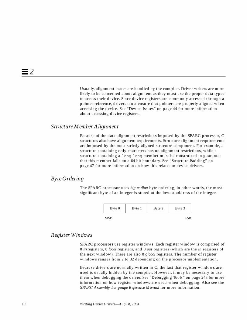
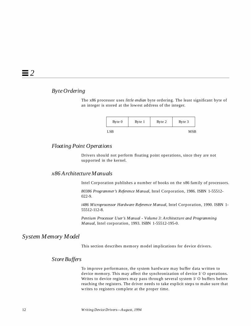
Byte Ordering
The SPARC processor uses big endian byte ordering; in other words, the mostsignificant byte of an integer is stored at the lowest address of the integer.
Register Windows
SPARC processors use register windows. Each register window is comprised of8 in registers, 8 local registers, and 8 out registers (which are the in registers ofthe next window). There are also 8 global registers. The number of registerwindows ranges from 2 to 32 depending on the processor implementation.
Because drivers are normally written in C, the fact that register windows areused is usually hidden by the compiler. However, it may be necessary to usethem when debugging the driver. See “Debugging Tools” on page 243 for moreinformation on how register windows are used when debugging. Also see theSPARC Assembly Language Reference Manual for more information.
Byte 0 Byte 1 Byte 2 Byte 3
MSB LSB
Hardware Overview 11
2
Floating Point Operations
Drivers should not perform floating point operations, since they are notsupported in the kernel.
Multiply and Divide Instructions
The Version 7 SPARC processors do not have multiply or divide instructions.These instructions are emulated in software and should be avoided. Since adriver cannot tell whether it is running on a Version 7 or Version 8 processor,intensive integer multiplication and division should be avoided if possible.Instead, use bitwise left and right shifts to multiply and divide by powers oftwo.
SPARC Architecture Manual
The SPARC Architecture Manual, Version 8, contains more specific informationon the SPARC CPU.
x86 Processor IssuesThis section describes a number of x86 processor-specific topics including dataalignment, byte ordering and floating point instructions.
Data Alignment
There are no alignment restrictions on data types. However, extra memorycycles may be required for the x86 processor to properly handle misaligneddata transfers.
Structure Member Alignment
See “Structure Padding” on page 47 for more information on how this relatesto device drivers.
12 Writing Device Drivers—August, 1994
2
Byte Ordering
The x86 processor uses little endian byte ordering. The least significant byte ofan integer is stored at the lowest address of the integer.
Floating Point Operations
Drivers should not perform floating point operations, since they are notsupported in the kernel.
x86 Architecture Manuals
Intel Corporation publishes a number of books on the x86 family of processors.
80386 Programmer’s Reference Manual, Intel Corporation, 1986. ISBN 1-55512-022-9.
i486 Microprocessor Hardware Reference Manual, Intel Corporation, 1990. ISBN 1-55512-112-8.
Pentium Processor User’s Manual - Volume 3: Architecture and ProgrammingManual, Intel corporation, 1993. ISBN 1-55512-195-0.
System Memory ModelThis section describes memory model implications for device drivers.
Store Buffers
To improve performance, the system hardware may buffer data written todevice memory. This may affect the synchronization of device I/O operations.Writes to device registers may pass through several system I/O buffers beforereaching the registers. The driver needs to take explicit steps to make sure thatwrites to registers complete at the proper time.
Byte 0 Byte 1 Byte 2 Byte 3
LSB MSB
Hardware Overview 13
2
For example, when acknowledging an interrupt, the driver usually sets orclears a bit in a device control register. The driver must ensure that the write tothe control register has reached the device before the interrupt handler returns.Similarly, if the device requires a delay (the driver busy-waits) after writing acommand to the control register, the driver must ensure that the write hasreached the device before delaying.
If the device registers can be read without undesirable side effects, verificationof a write can be as simple as reading the register immediately after writing toit. If that particular register cannot be read without undesirable side effects,another device register in the same register set can be used (seeddi_map_regs (9F)).
If no device register in the set can be read without undesirable side effects, oneof the ddi_poke (9F) routines may be used, as a last resort, to write to theregisters. When these routines return, they guarantee that the write hasreached the device.
Note – Future hardware platform implementations may not permit theddi_poke (9F) routines to guarantee that a write has reached a device. Driversshould avoid the use of ddi_poke (9F) for this purpose whenever possible.
SPARC Memory ModelThe SPARC memory model defines the semantics of memory operations suchas load and store and specifies how the order in which these operations areissued by a processor is related to the order in which they reach memory. Thememory model applies to both uniprocessors and shared-memorymultiprocessors. Two memory models are supported by the SPARC processor:Total Store Ordering (TSO) and Partial Store Ordering (PSO). All SPARCprocessors must support TSO.
TSO guarantees that the store, FLUSH, and atomic load-store instructions of allprocessors appear to be executed by memory serially in a single order calledthe memory order. Furthermore, the sequence of store, FLUSH, and atomicload-store instructions in the memory order for a given processor is identical tothe sequence in which they were issued by the processor.

14 Writing Device Drivers—August, 1994
2
Like the TSO memory model, PSO guarantees that the store, FLUSH, andatomic load-store instructions of all processors appear to be executed bymemory serially in a single order called the memory order. However, thememory order of store, FLUSH, and atomic load-store instructions for a givenprocessor is, in general, not the same as the order in which the instructionswere issued by that processor. Conformance between issuing order and memoryorder is provided by the STBAR instruction: if two of the above instructions areseparated by an STBAR in the issuing order of a processor, or if they referencethe same location, then the memory order of the two instructions is the same asthe issuing order.
See Chapter 6, Appendix J, and Appendix K of The SPARC Architecture Manual,Version 8 for more details on the SPARC memory model.
Bus ArchitecturesThis section describes a number of bus-specific topics including deviceidentification, device addressing, and interrupts.
Device Identification
Device identification is the process of determining which devices are present inthe system.
Self-Identifying Devices
Some devices are self-identifying—the device itself provides information to thesystem so that it can identify the device driver that needs to be used. Thedevice usually provides additional information to the system in the form ofname-value pairs that can be retrieved using the property interfaces. See“Properties” on page 57 for more information on properties.
SBus devices are examples of self-identifying devices. The information isusually derived from a small FORTH program stored in the FCode PROM onthe device. See sbus (4) for more information.

Hardware Overview 15
2
Non-Self-Identifying Devices
Devices that do not provide information to the system to identify themselvesare called non-self-identifying devices. Drivers for these devices must have aprobe (9E) routine which determines whether the device is really there. Inaddition, information about the device must be provided in a hardwareconfiguration file (see driver.conf (4)), so that the system can provideprobe (9E) with the information it needs to contact the device. See “probe( )”on page 93 for more information.
VMEbus, ISA, EISA, and MicroChannel devices are examples of non-self-identifying devices. SCSI target devices and pseudo devices are also non-self-identifying devices. See vme(4), isa(4) , scsi (4), and pseudo (4) for moreinformation.
Device Addressing
Device addressing is different on the buses that SunOS currently supports.
The SBus is geographically addressed; each SBus slot exists at a fixed physicaladdress in the system. An SBus card has a different address depending onwhich slot it is plugged into. Moving an SBus device to a new slot causes thesystem to treat it as a new device. See “Persistent Instances” on page 93 formore information.
On other buses, such as the VMEbus, each card has its own address, possiblyconfigurable by jumpers. A VMEbus card has the same address no matterwhich slot it is plugged into. Changing the address of a VME card causes thesystem to treat it as a new device.
Interrupts
SunOS supports polling interrupts and vectored interrupts.
The SBus uses polling interrupts. When an SBus device interrupts, the systemonly knows which of several devices might have issued the interrupt. Thesystem interrupt handler must ask the driver for each device whether it isresponsible for the interrupt.
16 Writing Device Drivers—August, 1994
2
The VMEbus uses vectored interrupts. When a VMEbus device interrupts, thesystem can identify which device is interrupting and call the correct devicedriver directly.
The Solaris 2.x DDI/DKI interrupt model is the same for both types of devices.See Chapter 6, “Interrupt Handlers,” for more information about interrupthandling.
Bus SpecificsThis section covers addressing and device configuration issues specific to thebuses that SunOS supports.
SBus
Typical SBus systems consist of a motherboard (containing the CPU and SBusinterface logic), a number of SBus devices on the motherboard itself, and anumber of SBus expansion slots. An SBus can also be connected to other typesof buses through an appropriate bus bridge.
Following is a discussion of how the SBus is implemented in theSPARCstation 1 and SPARCstation 1+.
Physical Address Space
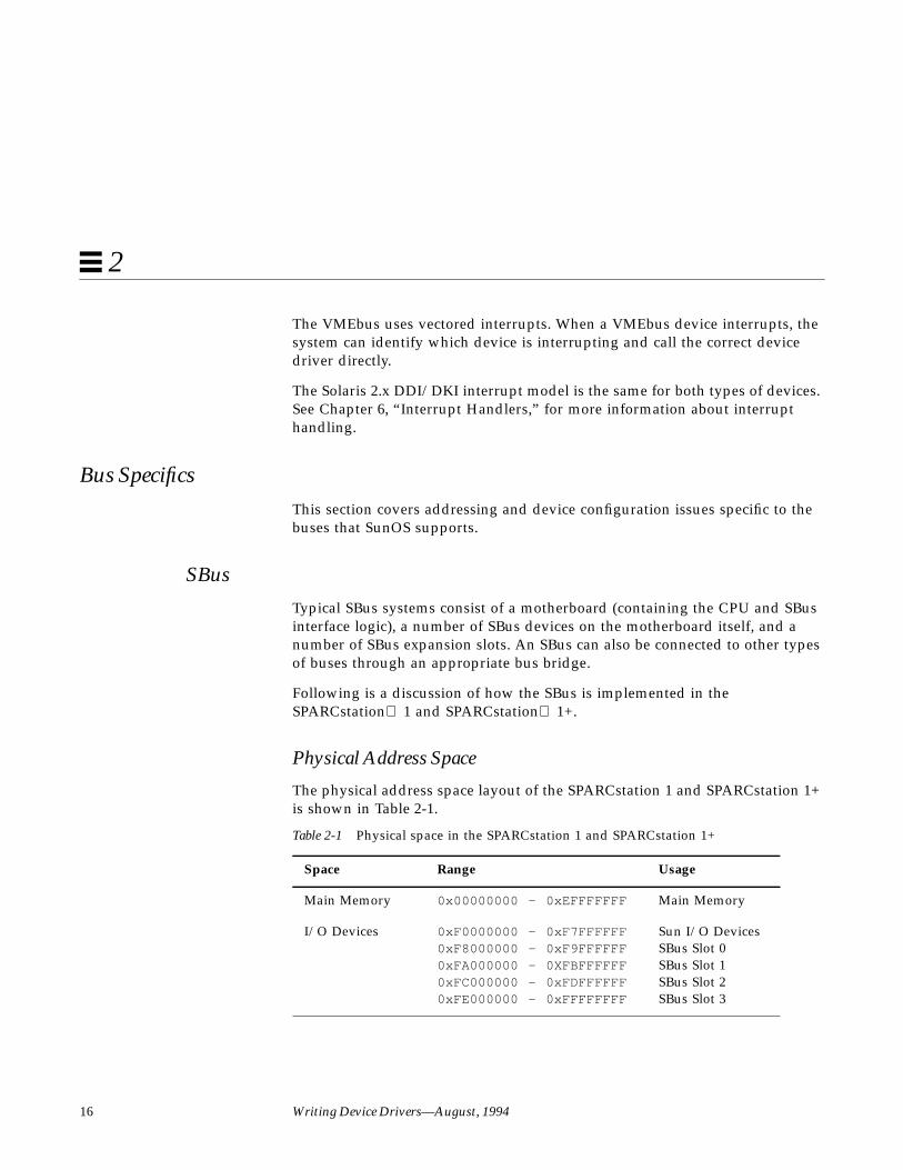
The physical address space layout of the SPARCstation 1 and SPARCstation 1+is shown in Table 2-1.
Table 2-1 Physical space in the SPARCstation 1 and SPARCstation 1+
Space Range Usage
Main Memory 0x00000000 - 0xEFFFFFFF Main Memory
I/O Devices 0xF0000000 - 0xF7FFFFFF0xF8000000 - 0xF9FFFFFF0xFA000000 - 0XFBFFFFFF0xFC000000 - 0xFDFFFFFF0xFE000000 - 0xFFFFFFFF
Sun I/O DevicesSBus Slot 0SBus Slot 1SBus Slot 2SBus Slot 3

Hardware Overview 17
2
Physical SBus Addresses
The address bus of the SPARC CPU has 32 bits. The SBus has 28 address bits,as described in the SBus Specification.
In the SPARCstation 1, the address bits are used as described in Table 2-2:
This addressing scheme yields the SPARCstation 1 and SPARCstation 1+addresses shown earlier in Table 2-1. Other implementations may use adifferent number of address bits.
SBus Slots
SBus systems have several SBus slots. The number of slots is system-specific.
The SPARCstation 1 has four SBus slots, numbered 0 through 3. Slot 0 isreserved; slots 1, 2 and 3 are available for SBus cards. The slots are used in thefollowing way:
• Slot 0 is not a physical slot, but refers to the on-board DMA, SCSI, andEthernet controllers. For convenience, these are viewed as being pluggedinto Slot 0.
• Slots 1 and 2 are physical slots that have DMA-master capability.
• Slot 3 is a slave-only physical slot that does not support boards that operateas DMA masters.
Table 2-2 SPARCstation 1 SBus address bits
Bits Description
0 - 24 These bits are the SBus address lines used by a SBus card toaddress the contents of the card.
25 - 26 Used by the CPU to select one of the SBus slots. These bitsgenerate the SlaveSelect lines.
27 Used by the CPU to distinguish between SBus devices anddevices resident on the CPU board. A one (1) indicates an SBusdevice, and a zero (0) indicates an on-board device.
28 - 31 Not used. For compatibility with Sun-4 architectureconventions, these bits are assumed to be all ones.

18 Writing Device Drivers—August, 1994
2
On other systems, for example the SPARCstation 10, slot 15 (slot 0xf) is the on-board slot, and slots 0-3 are available for SBus cards. Slots 4-14 are reserved.
Because some SBus systems (such as the SPARCstation 1) may not allow someslots to perform DMA, drivers that require DMA capability should useddi_slaveonly (9F) to determine if their device is in a DMA-capable slot. Foran example use of this function, see “attach( )” on page 95.
Hardware Configuration Files
Hardware configuration files should be unnecessary for SBus devices.However, on some occasions drivers for SBus devices may need to usehardware configuration files to augment the information provided by the SBuscard. See driver.conf (4) and sbus (4) for further details.
VMEbus
The VMEbus supports multiple address spaces. An appropriate entry in thedriver.conf (4) file should be made for the address space used by the device(generally, this is not under control of the driver). For DMA devices, theaddress space that the board uses for its DMA transfers must be known by thedriver (this is usually a 32- or 24-bit space).
Address Spaces
Sun-4 architecture machines that use a VMEbus are all based on the full 32-bitVMEbus. Table 2-3 contains a listing of the VMEbus address types supportedby the generic VMEbus.
Table 2-3 Generic VMEbus (full set)
VMEbus SpaceName
AddressSize
Data TransferSize
Physical AddressRange
vme32d16 32 bits 16 bits 0x0 – 0xFFFFFFFF
vme24d16 24 bits 16 bits 0x0 – 0xFFFFFF
vme16d16 16 bits 16 bits 0x0 – 0xFFFF

Hardware Overview 19
2
Not all of these address spaces are commonly used; nevertheless, they are allsupported on Sun-4 architecture systems. Table 2-4 indicates their sizes andphysical address mappings.
The type is a field in the page table entry used by the Sun4 MMU to implementthe virtual memory subsystem. It indicates the type of memory referenced:
• Type 0 - main memory• Type 1 - on-board I/O• Type 2 - VMEbus memory, 16 bit data• Type 3 - VMEbus memory, 32 bit data
Other Sun machines, such as the SPARCServer 600 series, have a differentformat for page table entries.
vme32d32 32 bits 32 bits 0x0 – 0xFFFFFFFF
vme24d32 24 bits 32 bits 0x0 – 0xFFFFFF
vme16d32 16 bits 32 bits 0x0 – 0xFFFF
Table 2-4 Page table types for the Sun-4
Type Address Space Name Address Range
0 On-board Memory 0x0 – 0xFFFFFFFF
1 On-board I/O 0x0 – 0xFFFFFF
2 vme32d16 0x0 – 0xFEFFFFFF
3 vme32d32 0x0 – 0xFEFFFFFF
2 vme24d16 —Stolen from top 16M of vme32d16 0x0 - 0xFEFFFF
2 vme16d16 —Stolen from top 64K of vme24d16 0x0 - 0xFFFF
3 vme24d32 —Stolen from top 16M of vme32d32 0x0 - 0xFEFFFF
3 vme16d32 —Stolen from top 64K of vme24d32 0x0 - 0xFFFF
Table 2-3 Generic VMEbus (full set)
VMEbus SpaceName
AddressSize
Data TransferSize
Physical AddressRange

20 Writing Device Drivers—August, 1994
2
When a smaller VME space overlays a larger VME space, it steals memoryfrom the larger space and is considered by the MMU to be part of the largeraddress space. There is no way to physically access VMEbus addresses above0xFF000000 in 32-bit VMEbus space, or above 0x00FF0000 in 24-bitVMEbus space.
Figure 2-1 illustrates the overlaying of VMEbus address apaces.
Figure 2-1 Sun-4 architecture VMEbus address spaces
Caution – There are restrictions on device addressing. The lower ranges of the32-bit and 24-bit VME space are reserved for DMA. For example, on the Sun-4architecture, devices must not be present in the low megabyte of VME address
vme24d32
vme16d16
vme24d16
vme16d32
OnBoardMemory
OnBoardI/O
MMUCPU
vme32d3232 bits
vme32d1632 bits
24 bits
32 bits
32 bits
2 bits
Type
32
bits
VirtualAddress
(CPU or DVMA)
PhysicalAddress

Hardware Overview 21
2
space or the system will not boot. In addition, there may be devices on the buswith addresses that conflict. These can be determined by examining thehardware configuration files.
Hardware Configuration Files
Most VME devices require hardware configuration files to inform the systemthat the device hardware may be present. The configuration file must specifythe device addresses on the VMEbus and any interrupt capabilities that thedevice has.
Configuration files for VMEbus devices should identify the parent bus driverimplicitly using the class key word and specifying class “vme.” This removesthe dependency on the name of the particular bus driver involved since thedriver may be named differently on different platforms. See driver.conf (4)and vme(4) for further details.
x86 Buses
Currently, there are three buses supported on the x86 platform:
• ISA - Industry Standard Architecture
• EISA - Extended Industry Standard Architecture
• MCA - MicroChannel Architecture
22 Writing Device Drivers—August, 1994
2
ISA Bus
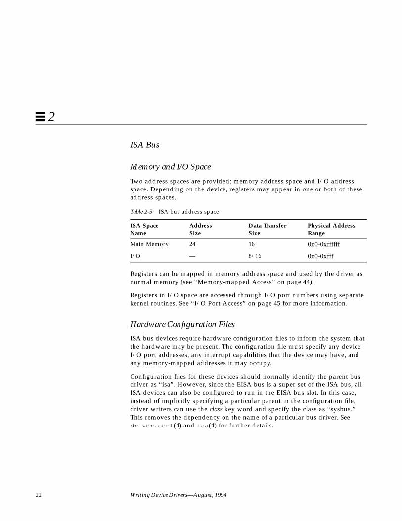
Memory and I/O Space
Two address spaces are provided: memory address space and I/O addressspace. Depending on the device, registers may appear in one or both of theseaddress spaces.
Registers can be mapped in memory address space and used by the driver asnormal memory (see “Memory-mapped Access” on page 44).
Registers in I/O space are accessed through I/O port numbers using separatekernel routines. See “I/O Port Access” on page 45 for more information.
Hardware Configuration Files
ISA bus devices require hardware configuration files to inform the system thatthe hardware may be present. The configuration file must specify any deviceI/O port addresses, any interrupt capabilities that the device may have, andany memory-mapped addresses it may occupy.
Configuration files for these devices should normally identify the parent busdriver as “isa”. However, since the EISA bus is a super set of the ISA bus, allISA devices can also be configured to run in the EISA bus slot. In this case,instead of implicitly specifying a particular parent in the configuration file,driver writers can use the class key word and specify the class as “sysbus.”This removes the dependency on the name of a particular bus driver. Seedriver.conf (4) and isa (4) for further details.
Table 2-5 ISA bus address space
ISA SpaceName
AddressSize
Data TransferSize
Physical AddressRange
Main Memory 24 16 0x0-0xffffff
I/O — 8/16 0x0-0xfff

Hardware Overview 23
2
EISA Bus
Memory and I/O Space
Two address spaces are provided: memory address space and I/O addressspace. Depending on the device, registers may appear in one or both of theseaddress spaces.
Registers can be mapped in memory address space and used by the driver asnormal memory (see “Memory-mapped Access” on page 44).
Registers in I/O space are accessed through I/O port numbers using separatekernel routines. See “I/O Port Access” on page 45) for more information.
Hardware Configuration Files
EISA bus devices require hardware configuration files to inform the systemthat the hardware may be present. The configuration file must specify anydevice I/O port addresses, any interrupt capabilities that the device may have,and any memory-mapped addresses it may occupy.
Configuration files for these devices should normally identify the parent busdriver as “eisa ”. See driver.conf (4) and eisa (4) for further details.
Table 2-6 EISA bus address space
EISA SpaceName
AddressSize
Data TransferSize
Physical AddressRange
Main Memory 32 32 0x0-0xffffffff
I/O — 8/16/32 0x0-0xffff

24 Writing Device Drivers—August, 1994
2
MCA Bus
Memory and I/O Space
Two address spaces are provided: memory address space and I/O addressspace. Depending on the device, registers may appear in one or both of theseaddress spaces.
Registers can be mapped in memory address space and used by the driver asnormal memory (see “Memory-mapped Access” on page 44).
Registers in I/O space are accessed through I/O port numbers using separatekernel routines. See “I/O Port Access” on page 45) for more information.
Hardware Configuration Files
MCA bus devices require hardware configuration files to inform the systemthat the hardware may be present. The configuration file must specify anydevice I/O port addresses, any interrupt capabilities that the device may have,and any memory-mapped addresses it may occupy.
Configuration files for these devices should normally identify the parent busdriver as “mca”. See driver.conf (4) and mca(4) for further details.
Device Issues
Timing-Critical Sections
While most driver operations can be performed without synchronization andprotection mechanisms beyond those provided by the locking primitivesdescribed in “Locking Primitives” on page 74, some devices require that asequence of events happen in order without interruption. In conjunction with
Table 2-7 MCA address space
MCA SpaceName
AddressSize
Data TransferSize
Physical AddressRange
Main Memory 32 32 0x0-0xffffffff
I/O — 8/16/32 0x0-0xfff

Hardware Overview 25
2
the locking primitives, the function ddi_enter_critical (9F) asks thesystem to guarantee, to the best of its ability, that the current thread willneither be preempted nor interrupted. This stays in effect until a closing call toddi_exit_critical (9F) is made. See ddi_enter_critical (9F) for details.
Delays
Many chips specify that they can be accessed only at specified intervals. Forexample, the Zilog Z8530 SCC has a “write recovery time” of 1.6 microseconds.This means that a delay must be enforced with drv_usecwait (9F) whenwriting characters with an 8530. In some instances, it is unclear what delays areneeded; in such cases, they must be determined empirically.
Internal Sequencing Logic
Devices with internal sequencing logic map multiple internal registers to thesame external address. There are various kinds of internal sequencing logic:
• The Intel 8251A and the Signetics 2651 alternate the same external registerbetween two internal mode registers. Writing to the first internal register isaccomplished by writing to the external register. This write, however, hasthe side effect of setting up the sequencing logic in the chip so that the nextread/write operation refers to the second internal register.
• The NEC PD7201 PCC has multiple internal data registers. To write a byteinto a particular register, two steps must be performed. The first step is towrite into register zero the number of the register into which the followingbyte of data will go. The data is then written to the specified data register.The sequencing logic automatically sets up the chip so that the next bytesent will go into data register zero.
• The AMD 9513 timer has a data pointer register that points at the dataregister into which a data byte will go. When sending a byte to the dataregister, the pointer is incremented. The current value of the pointer registercannot be read.
Interrupt Issues
The following are some common interrupt-related issues:
26 Writing Device Drivers—August, 1994
2
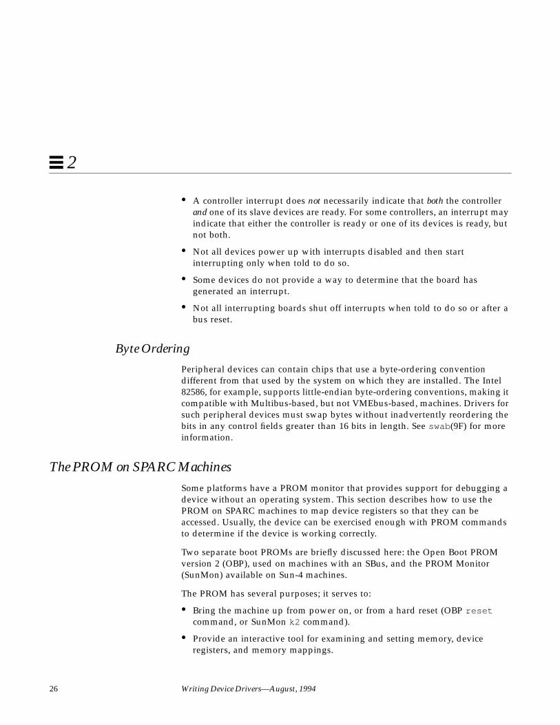
• A controller interrupt does not necessarily indicate that both the controllerand one of its slave devices are ready. For some controllers, an interrupt mayindicate that either the controller is ready or one of its devices is ready, butnot both.
• Not all devices power up with interrupts disabled and then startinterrupting only when told to do so.
• Some devices do not provide a way to determine that the board hasgenerated an interrupt.
• Not all interrupting boards shut off interrupts when told to do so or after abus reset.
Byte Ordering
Peripheral devices can contain chips that use a byte-ordering conventiondifferent from that used by the system on which they are installed. The Intel82586, for example, supports little-endian byte-ordering conventions, making itcompatible with Multibus-based, but not VMEbus-based, machines. Drivers forsuch peripheral devices must swap bytes without inadvertently reordering thebits in any control fields greater than 16 bits in length. See swab(9F) for moreinformation.
The PROM on SPARC MachinesSome platforms have a PROM monitor that provides support for debugging adevice without an operating system. This section describes how to use thePROM on SPARC machines to map device registers so that they can beaccessed. Usually, the device can be exercised enough with PROM commandsto determine if the device is working correctly.
Two separate boot PROMs are briefly discussed here: the Open Boot PROMversion 2 (OBP), used on machines with an SBus, and the PROM Monitor(SunMon) available on Sun-4 machines.
The PROM has several purposes; it serves to:
• Bring the machine up from power on, or from a hard reset (OBP resetcommand, or SunMon k2 command).
• Provide an interactive tool for examining and setting memory, deviceregisters, and memory mappings.

Hardware Overview 27
2
• Boot SunOS or the kernel debugger kadb (1M).
Simply powering up the computer and attempting to use its PROM to examinedevice registers will likely fail. While the device may be correctly installed,those mappings are SunOS specific and do not become active until SunOS isbooted. Upon power up, the PROM maps essential system devices, such as thekeyboard.
Examples in this section use a bwtwo (monochrome) frame buffer on aSPARCstation IPC. Using PROM commands to modify video memory on thisframe buffer provides a visual indication that something is happening whenPROM commands are executed.
Open Boot PROM 2.x
For complete documentation on the Open Boot PROM, see the Open BootPROM Toolkit User’s Guide and monitor (1M). The examples in this sectionrefer to a Sun-4c; other architectures may require new commands to mapmemory, among other things.
The Open Boot PROM is currently used on Sun machines with an SBus. It ismore powerful than the older SunMon (“The Sun Monitor” on page 34). TheOpen Boot PROM uses an “ok ” prompt rather than the “>” prompt used bySunMon. However, many Open Boot PROM machines present the old-styleinterface by default. The ‘n’ command switches an OBP from the old mode tothe new mode.
Note – If the PROM is in secure mode (the security-mode parameter is not setto none) the PROM password may be required (set in the security-password parameter).
Type b (boot), c (continue), or n (new command mode)>nType help for more informationok

28 Writing Device Drivers—August, 1994
2
To make the machine come up in new mode by default, set the environmentvariable sunmon-compat? to false.
The printenv command displays all parameters and their values.
Help
Help is available with the help command.
History
EMACS-style command-line history is available. Use Control-N (next) andControl-P (previous) to walk the history list.
Forth Commands
The Open Boot PROM uses the Forth programming language. This is a stack-based language; arguments must be pushed on the stack before running thedesired command (called a word), and the result is left on the stack.
To place a number on the stack, type its value.
To add the two top values on the stack, use the + operator.
The result is left on the stack. The stack is shown with the .s word.
ok setenv sunmon-compat? falsesunmon-compat? = false
ok 57ok 68
ok +
ok .sbf
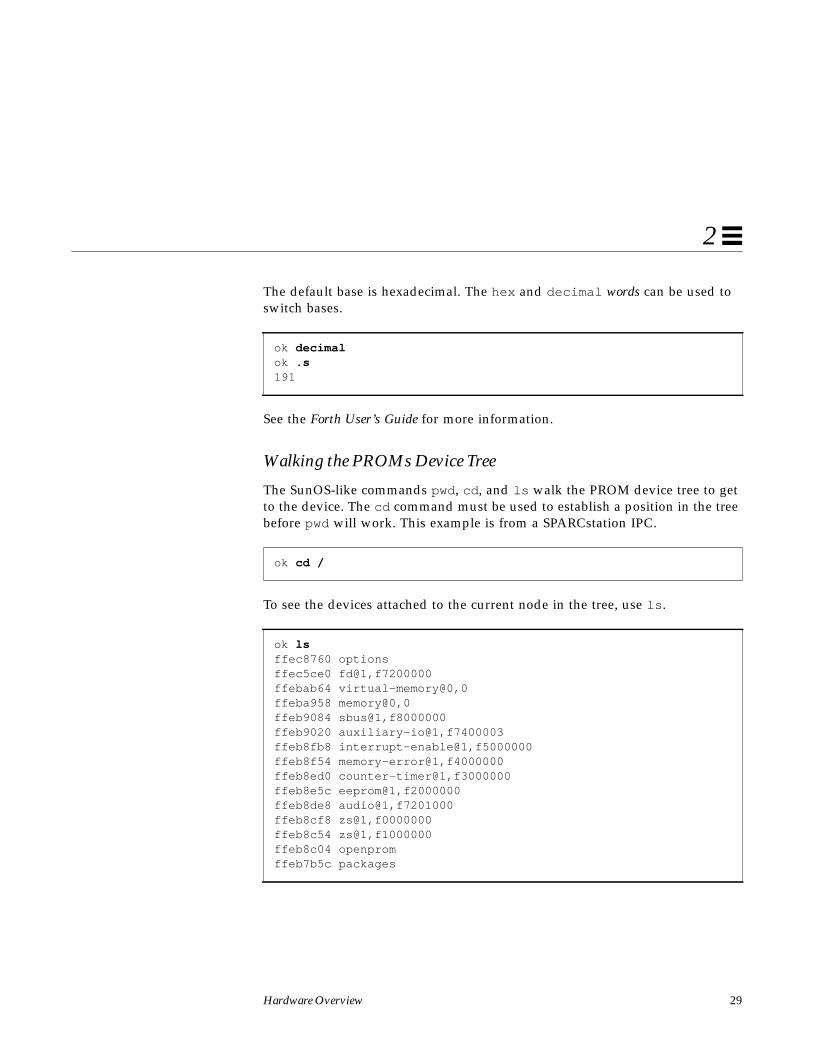
Hardware Overview 29
2
The default base is hexadecimal. The hex and decimal words can be used toswitch bases.
See the Forth User’s Guide for more information.
Walking the PROMs Device Tree
The SunOS-like commands pwd, cd , and ls walk the PROM device tree to getto the device. The cd command must be used to establish a position in the treebefore pwd will work. This example is from a SPARCstation IPC.
To see the devices attached to the current node in the tree, use ls .
ok decimalok .s191
ok cd /
ok lsffec8760 optionsffec5ce0 fd@1,f7200000ffebab64 virtual-memory@0,0ffeba958 memory@0,0ffeb9084 sbus@1,f8000000ffeb9020 auxiliary-io@1,f7400003ffeb8fb8 interrupt-enable@1,f5000000ffeb8f54 memory-error@1,f4000000ffeb8ed0 counter-timer@1,f3000000ffeb8e5c eeprom@1,f2000000ffeb8de8 audio@1,f7201000ffeb8cf8 zs@1,f0000000ffeb8c54 zs@1,f1000000ffeb8c04 openpromffeb7b5c packages

30 Writing Device Drivers—August, 1994
2
The full node name can be used:
Rather than using the full node name in the previous example, you could haveused an abbreviation. The abbreviated command line entry looks like this:
The name is actually device@slot,offset (for SBus devices). The bwtwo device is inslot 3 and starts at offset 0. If an SBus device shows up in this tree, the devicehas been recognized by the PROM.
The .attributes command displays the PROM properties of a device. Thesecan be examined to determine what properties the device exports (this is usefullater to ensure that the driver is looking for the correct hardware properties).These are the same properties that can be retrieved with ddi_getprop(9F) .See sbus(4) and “Properties” on page 57 for related information.
The reg property defines an array of register description structures, containingthe following fields:
u_int bustype; /* cookie for related bus type*/u_int addr; /* address of reg relative to bus */u_int size; /* size of this register set */
For the bwtwo example, the address is 0.
ok cd sbus@1,f8000000ok lsffecd450 bwtwo@3,0ffecc2f0 le@0,c00000ffec9b38 esp@0,800000ffec9af4 dma@0,400000
ok cd sbus
ok cd bwtwook .attributesmonitor-sense 00 00 00 03intr 00 00 00 07 00 00 00 00reg 00 00 00 03 00 00 00 00 01 00 00 00device_type displaymodel SUNW,501-1561...

Hardware Overview 31
2
Mapping the Device
To test the device, it must be mapped into memory. The PROM can then beused to verify proper operation of the device by using data-transfer commandsto transfer bytes, words, and long words. If the device can be operated fromthe PROM, even in a limited way, the driver should also be able to operate thedevice.
To set up the device for initial testing perform the following three steps:
1. Determine the physical address of the SBus slot the device is in. Table 2-8displays the physical addresses of various SBus slots on a SPARCstation 1and SPARCstation 1+:
In this example, the bwtwo device is located in slot 3. Consequently, thephysical address space for the device is 0x6000000.
2. Determine the offset within the physical address space used by the device.
The offset used is specific to the device. In the bwtwo example, the videomemory happens to start at offset 0x800000 within the bwtwo space. As aresult, the actual offset to be mapped is 0x6800000.
3. Use the map-sbus word to map the device in.
The map-sbus word takes an offset and a size as arguments to map. Like theoffset, the size of the byte transfer is specific to the device. In the bwtwoexample, the size is set to 20000 bytes.
Table 2-8 SBus physical addresses
SBus Slot Number Physical Address Space
SBus slot #0 0 (internal slot)
SBus slot #1 0x2000000
SBus slot #2 0x4000000
SBus slot #3 0x6000000

32 Writing Device Drivers—August, 1994
2
In the code example below, the offset and size values for the frame buffer aredisplayed as arguments to the map-sbus word. Notice that the virtualaddress to use is left on top of the stack. The stack is then shown using the .sword. It can be assigned a name with the constant operation.
Reading and WritingThe PROM provides a variety of 8-bit, 16-bit, and 32-bit operations. In general,a c (character) prefix indicates an 8-bit (one byte) operation; a w (word) prefixindicates a 16-bit (two byte) operation; and an L (longword) prefix indicates a32-bit (four byte) operation.
A suffix of ! is used to indicate a write operation. The write operation takes thefirst two items off the stack; the first item is the address, and the second item isthe value.
A suffix of @ is used to indicate a read operation. The read operation takes oneargument (the address) the off the stack. .
A suffix of ? is used to display the value, without affecting the stack.
ok 6800000 20000 map-sbusok .sffe7f000ok constant fb
ok 55 ffe8000 c!
ok ffe80000 c@ok .s77
ok ffe80000 c?77

Hardware Overview 33
2
Be careful when trying to query the device. If the mappings are not set upcorrectly, trying to read or write could cause errors. There are special wordsprovided to handle these cases. cprobe , wprobe , and lprobe , for example,read from the given address but return zero if the location does not respond, ornonzero if it does.
A region of memory can be shown with the dump word. This takes an addressand a length, and displays the contents of the memory region in bytes.
In the following example the fill word is used to fill video memory with apattern. fill takes the address, the number of bytes to fill, and the byte to use(there is also a wfill and an Lfill for words and longwords). This causes thebwtwo to display simple patterns based on the byte passed.
Interrupts
Certain machine-specific interrupt levels are ignored when the Open BootPROM controls the machine.
ok ffee0000 c@Data Access Exceptionok ffee0000 cprobeok .s0ok ffe80000 cprobeok .s0 ffffffff
ok 6800000 20000 map-sbusok constant fbok fb 20000 ff fillok fb 20000 0 fillok fb 18000 55 fillok fb 15000 3 fillok fb 10000 5 fillok fb 5000 f9 fill

34 Writing Device Drivers—August, 1994
2
The Sun Monitor
Normally, the Sun Monitor is used on Sun-4 architectures with a VMEbus. Forcomplete documentation on SunMon, see the PROM User’s Guide.
Mapping the Device
To test the device, it must be mapped into memory. The PROM can then beused to verify proper operation by using data-transfer commands to transferbytes, words, and long words. If the device can be made to operate from thePROM, even in a limited way, the driver should also be able to operate thedevice.
To set up the device for initial testing:
1. Select an appropriate virtual address for the testing of the device.
2. Determine the physical address of the device, as well as the address spacethat it occupies.
3. Use the monitor to map the system’s virtual address to the device’s physicaladdress.
Selecting a Virtual AddressWhen mapping a virtual address to a physical address, the MMU is actuallymapping to a page of physical memory and an offset within that page. Thelow-order bits of a virtual address, those that specify the offset, are not mapped.See Figure 2-2 on page 35.
The mapping mechanism is essentially the same for all systems, though thedetails of the address size and page mapping differ.

Hardware Overview 35
2
Figure 2-2 Sun-4 architecture address mapping
The easiest way to select a virtual address for testing is to use one between0x4000 and 0x100000. Addresses in this range are unused by the PROM in Sun-4 architecture machines and are available. Be aware that these addresses, whileconvenient for testing, are not those that the kernel chooses when the driver isfinally installed.
It is most convenient to select a virtual address that has only zeros in its low-order bits. This way, the first address in a virtual page is selected. The low-order bits in the chosen address remain unchanged. With ‘X’ representing theunmapped low-order bits (13 on an 8K page Sun-4) the test address 0x4000 is,in binary:
0000 0000 0000 0000 010X XXXX XXXX XXXX
Finding a Physical AddressThe device may be preconfigured to some address. If it is, then that addressshould be used unless it conflicts with the address of an already installeddevice. If it conflicts, an unused physical address must be found. To do so,examine the hardware configuration files in /kernel/drv and/usr/kernel/drv on the test system. See driver.conf(4) for moreinformation on hardware configuration files and vme(4) for specificinformation on configuration files for VMEbus devices.
MMU
PhysicalAddress
VirtualAddress
Input Output
low
32 bits high 32 bits
13
19high19

36 Writing Device Drivers—August, 1994
2
Creating a Page Table EntryThe link between the virtual and physical address is the MMU. The MMUcontains a page table to keep track of which virtual pages map to whichphysical pages. Entries in this table are called page table entries (PTE). Tocreate a mapping, a page table entry must be constructed. On a Sun-4, PTEs are32-bit numbers with the following structure:
Note – This discussion is for informational and debugging use only. Devicedrivers must not manipulate page table entries.
The following is a “template” bit mask that can be used to construct standardPTEs. An acceptable mask assumes values as follows:
V (valid) = 1w/s (write ok/supervisor only) = 11c (don’t cache) = 1(a/m) accessed/modified = 00unused = 00000
A one in the don’t cache position only disables caching if the type is zero, sinceother types of pages are never cached. Substituting the above values, thetemplate looks like this:
a mV w s c Physical Page Number (19)Unused
Type
0 01 1 1 1 0 0 0 0 0 Physical Page Number (19)
Type

Hardware Overview 37
2
This results in a mask of 0xF0000000 (assuming that the type field is 00). Thus,the four masks for the four types of memory are:
To determine the value to be plugged into the PTE, the appropriate mask isadded to the physical page number, resulting in the full 32-bit PTE. Followingare some rules for generating PTEs with the correct template, based on theaddress space the device is in and assuming an 8K page size:
If the device is in vme16d16, vme24d16, or vme32d16 Use Type-2 Template
If the device is in vme16d32, vme24d32, or vme32d16 Use Type-3 Template
If the device is in vme32d16 or vme32d32 Physical Page Number = Physical Address >> 13
If the device is in vme24d16 or vme24d32 Physical Page Number = (Physical Address + 0xFF000000) >> 13
If the device is in vme16d16 or vme16d32 Physical Page Number = (Physical Address + 0xFFFF0000) >> 13
Example OneA device is attached at physical address 0x280008 in bus type vme24d16, whichwill be mapped into virtual memory at address 0xE000000. What is thecorresponding PTE?
Table 2-9 PTE masks
Type Description Mask
0 On Board Memory 0xF0000000
1 On Board I/O Space 0xF4000000
2 vme16d16 0xF8000000
2 vme24d16 0xF8000000
2 vme32d16 0xF8000000
3 vme16d32 0xFC000000
3 vme24d32 0xFC000000
3 vme32d32 0xFC000000

38 Writing Device Drivers—August, 1994
2
Answer: 0xF807F940
Explanation: Because the device is being mapped into vme24d16, 0xF8000000 isused as the template. Adding the physical address to 0xFF000000 yields0xFF280008. In binary, this is:
1111 1111 0010 1000 0000 0000 0000 1000
Shifting this right by 13 yields:
XXXX XXXX XXXX X111 1111 1001 0100 0000
Adding the 0xF8000000 template results in values for the 13 bits that areundefined from the shift. The PTE is:
1111 1000 0000 0111 1111 1001 0100 0000
In hexadecimal, this is 0xF807F940.
The resulting PTE maps the virtual page beginning at 0xE000000 to thephysical page containing 0x280008. To get the virtual address to access thedevice, it is necessary to take the lower 13 bits of the physical installationaddress—the bits that are just passed through the MMU— and add them tovirtual address 0xE000000. The lower 13 bits of physical address 0x280008 are0008; adding them to 0xE000000 yields 0xE000008, the virtual address by whichthe device can be accessed.
Example TwoA device at physical address 0xEE48 on bus type vme16d32 will be mapped tovirtual address 0xE000000. What is the PTE?
Answer: 0xFC07FFFF
Explanation: Because the device is being mapped into vme16d32, 0xFC000000is used as the template. Adding the physical address to 0xFFFF0000 yields0xFFFFEE48. In binary, this is:
1111 1111 1111 1111 1110 1110 0100 1000
Shifting this right by 13 yields:
XXXX XXXX XXXX X111 1111 1111 1111 1111
Adding the 0xFC000000 template results in values for the 13 bits that areundefined from the shift. The PTE is:
1111 1100 0000 0111 1111 1111 1111 1111

Hardware Overview 39
2
This is 0xFC07FFFF in hexadecimal.
To get the virtual address to access the device at physical address 0xEE48, addits lower 13 bits, 0xE48, to 0xE000000. This yields 0xE000E48.
Sun 4/110 ConsiderationsThe Sun-4/110 MMU does not store bits 28-31. For the VMEbus, which uses 32bits of physical addressing, bits 28-31 are generated by sign-extending bit 27.When the PTE is read back, these upper bits are always set to zero. Thisessentially creates a hole in the address space that is not addressable.
When entering page table entries on a Sun-4/110 to test hardware from thePROM, use a virtual address less than 0x800000. Virtual addresses at or above0x800000 are not set up by the PROM for use.
When mapping the device to vme16, vme24, or the top half of the vme32address space, after entering the PTE the top five bits of the physical pagenumber are zero because the Sun-4/110 physical address space is split with 128megabytes at the bottom and 128 megabytes at the top. Whenever the physicaladdress goes above 128 megabytes, the high bit is sign extended so that theaddress lies within the top 128 megabytes. Sign extending the high bit into thenext five bits should result in the previously calculated physical page number.
In this example, instead of using 0xE000000 as the starting address, the value0xE0000 could be used successfully.
Mapping Commands
1. Issue the PROM command that puts the CPU into supervisor data state:
2. Calculate the PTE appropriate to the chosen physical address.
3. Map the virtual address to the device. The PROM p command will do this,given a virtual address:
> s B
> p F32000

40 Writing Device Drivers—August, 1994
2
This command takes the virtual address 0xF32000 as its argument anddisplays the PTE for it. It also displays a ?, which indicates that a new valuemay be typed in to replace the one displayed. Note that all virtual addresseswithin a page select the same PTE. Type any non-hexadecimal character tostop.
4. Repeat step 3 for each page to map.
Reading and Writing
The format of the data transfer commands are
command [address] [value]
Valid commands are:
o open a bytee open a word (4 bytes)l open a longword (4 bytes)
When using the o, e, or l commands to open a location, the monitor reads thepresent contents of that location and displays it before giving the option torewrite it. To do the write without the read (because the device does somethingelse when the read occurs), pass a value after the address argument; this isknown as a blind write.

43
Overview of SunOS Device Drivers 3
This chapter gives an overview of SunOS device drivers. It discusses what adevice driver is and the types of device drivers that SunOS supports. It alsoprovides a general discussion of the routines that device drivers mustimplement and points out compiler-related issues.
What is a Device Driver?A device driver is a kernel module containing subroutines and data responsiblefor managing low-level I/O operations for a particular hardware device.Device drivers can also be software-only, emulating a device such as a RAMdisk or a pseudo-terminal that only exists in software. Such device drivers arecalled pseudo device drivers and cannot perform functions requiring hardware(such as DMA).
A device driver contains all the device-specific code necessary to communicatewith a device and provides a standard I/O interface to the rest of the system.This interface protects the kernel from device specifics just as the system callinterface protects application programs from platform specifics. Applicationprograms and the rest of the kernel need little (if any) device-specific code toaddress the device. In this way, device drivers make the system more portableand easier to maintain.

44 Writing Device Drivers—August, 1994
3
Types of Device DriversThere are several kinds of device drivers, each handling a different kind ofI/O. Block device drivers manage devices with physically addressable storagemedia, such as disks. All other devices are considered character devices. Thereare two types of character device drivers: standard character device driversand STREAMS device drivers.
Block Device Drivers
Devices that support a file system are known as block devices. Drivers writtenfor these devices are known as block device drivers. Block device drivers takea file system request (in the form of a buf (9S) structure) and make the devicetransfer the specified block. The main interface to the file system is thestrategy (9E) routine. See Chapter 9, “Drivers for Block Devices” for moreinformation.
Block device drivers can also provide a character driver interface that allowsutility programs to bypass the file system and access the device directly. Thisdevice access is commonly referred to as the raw interface to a block device.
Standard Character Device Drivers
Character device drivers normally perform I/O in a byte stream. They can alsoprovide additional interfaces not present in block drivers, such as I/O control(ioctl (9E)) commands, memory mapping, and device polling. See Chapter 8,“Drivers for Character Devices” for more information.
Byte-Stream I/O
The main job of any device driver is to perform I/O, and many characterdevice drivers do what is called bytestream or character I/O. The drivertransfers data to and from the device without using a specific device address.This is in contrast to block device drivers, where part of the file system requestidentifies a specific location on the device.
The read (9E) and write (9E) entry points handle bytestream I/O for standardcharacter drivers. See “I/O Request Handling” on page 153 for moreinformation.
Overview of SunOS Device Drivers 45
3
I/O Control
Many devices have characteristics and behaviors that can be configured ortuned. The ioctl (2) system call and the ioctl (9E) driver entry point providea mechanism for application programs to change and determine the status of adriver’s configurable characteristics. The baud rate of a serial communicationsport, for example, is usually configurable in this way.
The I/O control interface is open ended, allowing device drivers to definespecial commands for the device. The definition of the commands is entirelyup to the driver and is restricted only by the requirements of the applicationprograms using the device and the device itself.
Certain classes of devices such as frame buffers or disks must support standardsets of I/O control requests. These standard I/O control interfaces aredocumented in the Solaris 2.4 Reference Manual AnswerBook. For example,fbio (7) documents the I/O controls that frame buffers must support, anddkio (7) documents standard disk I/O controls. See “Miscellaneous I/OControl” on page 165 for more information on I/O control.
Note – The I/O control commands in section 7 are not part of the Solaris 2.xDDI/DKI.
Memory Mapping
For certain devices, such as frame buffers, it is more efficient for applicationprograms to have direct access to device memory. Applications can map devicememory into their address spaces using the mmap(2) system call. To supportmemory mapping, device drivers implement segmap(9E) and mmap(9E) entrypoints. See Chapter 11, “Device Context Management” for details.
Drivers that define an mmap(9E) entry point usually do not define read (9E)and write (9E) entry points, since application programs perform I/O directlyto the devices after calling mmap(2). See Chapter 11, “Device ContextManagement”, for more information on I/O control.

46 Writing Device Drivers—August, 1994
3
Device Polling
The poll (2) system call allows application programs to monitor or poll a set offile descriptors for certain conditions or events. poll (2) is used to find outwhether data are available to be read from the file descriptors or whether datamay be written to the file descriptors without delay. Drivers referred to bythese file descriptors must provide support for the poll (2) system call byimplementing a chpoll (9E) entry point.
Drivers for communication devices such as serial ports should support pollingsince they are used by applications that require synchronous notification ofchanges in read and write status. Many communications devices, however, arebetter implemented as STREAMS drivers.
STREAMS Drivers
STREAMS is a separate programming model for writing a character device.Devices that receive data asynchronously (such as terminal and networkdevices) are suited to a STREAMS implementation. STREAMS device driversmust provide the loading and autoconfiguration support described inChapter 5, “Autoconfiguration.” See the STREAMS Programmer’s Guide foradditional information on how to write STREAMS drivers.
Device Issues
Accessing Device Registers
There are two common ways of accessing device registers: through memory-mapping and I/O ports. The preferred method depends on the device; it is notgenerally software-configurable. For example, SBus and VMEbus devices donot provide I/O ports, but some ISA, MCA, and EISA devices may provideboth access methods.
Memory-mapped Access
In memory-mapped access, device registers appear in memory address spaceand are treated as normal memory. Just as the driver needs a kernel virtualaddress to access physical memory, the driver also needs a virtual address to

Overview of SunOS Device Drivers 47
3
access any device registers. To get a virtual address, the driver must map thedevice registers into kernel virtual memory. The Solaris 2.x DDI/DKI providesthis ability with the ddi_map_regs (9F) function.
volatile char *reg_addr;
ddi_map_regs(..., (caddr_t) ®_addr, ...);
Once the registers are successfully mapped, they can be accessed as any othermemory. The following example writes one byte to the first location mapped(hexadecimal notation is usually used when writing bits):
*reg_addr = 0x10;
I/O Port Access
In I/O port access, the device registers appear in I/O address space. Eachaddressable element of the I/O address space is called an I/O port. Deviceregisters are accessed through I/O port numbers, which are defined by thehardware. These port numbers can refer to 8, 16, or 32-bit registers. Readingfrom a port is accomplished with one of the inb (9F) family of routines. Writingto a port is performed with an outb (9F) routine.
On x86 systems, device registers are typically accessed through I/O ports.Large buffers, on the other hand, are accessed using memory mapping.
Example Device Registers
Most of the examples in this manual use a fictitious device that has an 8-bitcommand/status register (csr), followed by an 8-bit data register. Thecommand/status register is so called because writes to it go to an internalcommand register, and reads from it are directed to an internal status register.
The command register looks like this:
Clear Interrupt
Start Transfer
Enable Interrupts

48 Writing Device Drivers—August, 1994
3
The status register looks like this:
Many drivers provide macros for the various bits in their registers to make thecode more readable. The examples in this manual use the following names forthe bits in the command register:
#define ENABLE_INTERRUPTS 0x10#define CLEAR_INTERRUPT 0x08#define START_TRANSFER 0x04
For the bits in the status register, the following macros are used:
#define INTERRUPTS_ENABLED 0x10#define INTERRUPTING 0x08#define DEVICE_BUSY 0x04#define DEVICE_ERROR 0x02#define TRANSFER_COMPLETE 0x01
Device Register Structure
Using pointer accesses to communicate with the device results in unreadablecode. For example, the code that reads the data register when a transfer hascompleted might look like this:
if (*reg_addr & TRANSFER_COMPLETE) {data = *(reg_addr + 1); /* read data */
}
To make the code more readable, it is common to define a structure thatmatches the layout of the devices registers. In this case, the structure couldlook like this:
struct device_reg {volatile u_char csr;volatile u_char data;
};
The driver then maps the registers into memory and refers to them through apointer to the structure:
Interrupt PendingInterrupts Enabled
Device Busy
Transfer Complete
Error Occurred
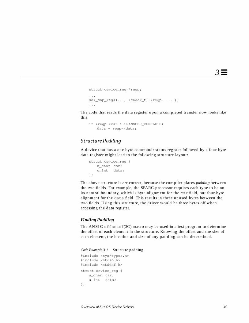
Overview of SunOS Device Drivers 49
3
struct device_reg *regp;
...ddi_map_regs(..., (caddr_t) ®p, ... );...
The code that reads the data register upon a completed transfer now looks likethis:
if (regp->csr & TRANSFER_COMPLETE)data = regp->data;
Structure Padding
A device that has a one-byte command/status register followed by a four-bytedata register might lead to the following structure layout:
struct device_reg {u_char csr;u_int data;
};
The above structure is not correct, because the compiler places padding betweenthe two fields. For example, the SPARC processor requires each type to be onits natural boundary, which is byte-alignment for the csr field, but four-bytealignment for the data field. This results in three unused bytes between thetwo fields. Using this structure, the driver would be three bytes off whenaccessing the data register.
Finding PaddingThe ANSI C offsetof (3C) macro may be used in a test program to determinethe offset of each element in the structure. Knowing the offset and the size ofeach element, the location and size of any padding can be determined.
Code Example 3-1 Structure padding
#include <sys/types.h>#include <stdio.h>#include <stddef.h>
struct device_reg {u_char csr;u_int data;
};

50 Writing Device Drivers—August, 1994
3
int main(void){
printf("The offset of csr is %d, its size is %d.\n",offsetof(struct device_reg, csr), sizeof (u_char));
printf("The offset of data is %d, its size is %d.\n",offsetof(struct device_reg, data), sizeof (u_int));
return (0);}
Here is a sample compilation with SPARCompilers 2.0.1 and a subsequent runof the program:
Driver developers should be aware that padding is dependent not only on theprocessor but also on the compiler.
Driver InterfacesThe kernel expects device drivers to provide certain routines that mustperform certain operations; these routines are called entry points. This is similarto the requirement that application programs have a _start ( ) entry point orthat C applications have the more familiar main ( ) routine.
Entry Points
Each device driver defines a standard set of functions called entry points, whichare defined in the Solaris 2.4 Reference Manual AnswerBook. Drivers for differenttypes of devices have different sets of entry points according to the kinds ofoperations the devices perform. A driver for a memory-mapped character-oriented device, for example, supports an mmap(9E) entry point, while a blockdriver does not.
Some operations are common to all drivers, such as the functions that arerequired for module loading (_init (9E), _info (9E), and _fini (9E)), and therequired autoconfiguration entry points identify (9E), attach (9E), andgetinfo (9E)). Drivers may also support the optional autoconfiguration entry
test% cc -Xa c.ctest% a.outThe offset of csr is 0, its size is 1.The offset of data is 4, its size is 4.

Overview of SunOS Device Drivers 51
3
points for probe (E) and detach (9E). All device drivers must support theentry point getinfo (9E). Most drivers have open (9E) and close (9E) entrypoints to control access to their devices. See Chapter 8, “Drivers for CharacterDevices,” Chapter 9, “Drivers for Block Devices,” and Chapter 5,“Autoconfiguration,” for details about these entry points.
Traditionally, all driver function and variable names have some prefix added tothem. Usually, this is the name of the driver, such as xxopen() for the open (9E)routine of driver xx. In subsequent examples, xx is used as the driver prefix.
Note – In SunOS 5.x, only the loadable module routines must be visible outsidethe driver object module. Everything else can have the storage class static .
Loadable Module Routinesint _init(void);
int _info(struct modinfo *modinfop);
int _fini(void);
All drivers must implement the _init (9E), _fini (9E) and _info (9E) entrypoints to load, unload and report information about the driver module. Thedriver is single-threaded when the kernel calls _init . No other thread willenter a driver routine until mod_install (9F) returns success.
Any resources global to the device driver should be allocated in _init (9E)before calling mod_install (9F) and should be released in _fini (9E) aftercalling mod_remove (9F).
These routines have kernel context.
Note – Drivers must use these names, and they must not be declared static ,unlike the other entry points where the names and storage classes are up to thedriver.
Autoconfiguration Routinesstatic int xxidentify(dev_info_t *dip);
static int xxprobe(dev_info_t *dip);
static int xxattach(dev_info_t *dip, ddi_attach_cmd_t cmd);

52 Writing Device Drivers—August, 1994
3
static int xxdetach(dev_info_t *dip, ddi_detach_cmd_t cmd);
static int xxgetinfo(dev_info_t *dip,ddi_info_cmd_t infocmd,void *arg, void **result);
The driver is single-threaded on a per-device basis when the kernel calls theseroutines, with the exception of getinfo (9E). The kernel may be in amultithreaded state when calling getinfo (9E), which can occur at any time.No calls to attach (9E) will occur on the same device concurrently. However,calls to attach (9E) on different devices that the driver handles may occurconcurrently.
Any per-device resources should be allocated in attach (9E) and released indetach (9E). No resources global to the driver should be allocated inattach (9E).
These routines have kernel context.
Block Driver Entry Pointsint xxopen(dev_t *devp, int flag, int otyp, cred_t *credp);
int xxclose(dev_t dev, int flag, int otyp, cred_t *credp);
int xxstrategy(struct buf *bp);
int xxprint(dev_t dev, char *str);
int xxdump(dev_t dev, caddr_t addr, daddr_t blkno, int nblk);
int xxprop_op(dev_t dev, dev_info_t *dip, ddi_prop_op_t prop_op, int mod_flags, char *name, caddr_t valuep, int *length);
These routines have kernel context.
Character Driver Entry Pointsint xxopen(dev_t *devp, int flag, int otyp, cred_t *credp);
int xxclose(dev_t dev, int flag, int otyp, cred_t *credp);
int xxread(dev_t dev, struct uio *uiop, cred_t *credp);
int xxwrite(dev_t dev, struct uio *uiop, cred_t *credp);
int xxioctl(dev_t dev, int cmd, int arg, int mode,cred_t *credp, int *rvalp);
int xxmmap(dev_t dev, off_t off, int prot);

Overview of SunOS Device Drivers 53
3
int xxsegmap(dev_t dev, off_t off, struct as *asp,caddr_t *addrp, off_t len, unsigned int prot,unsigned int maxprot, unsigned int flags,cred_t *credp);
int xxchpoll(dev_t dev, short events, int anyyet,short *reventsp, struct pollhead **phpp);
int xxprop_op(dev_t dev, dev_info_t *dip,ddi_prop_op_t prop_op, int mod_flags,char *name, caddr_t valuep, int *length);
With the exception of prop_op (9E), all these routines have user context.prop_op (9E) has kernel context.
Callback functionsSome routines provide a callback mechanism. This is a way to schedule afunction to be called when a condition is met. Typical conditions for whichcallback functions are set up include:
• When a transfer has completed
• When a resource might become available
• When a timeout period has expired
Transfer completion callbacks perform the tasks usually done in an interruptservice routine.
In some sense, callback functions are similar to entry points. The functions thatallow callbacks expect the callback function do to certain things. In the case ofDMA routines, a callback function must return a value indicating whether thecallback function wants to be rescheduled in case of a failure.
Callback functions execute as a separate thread. They must consider all theusual multithreading issues.
Note – All scheduled callback functions must be canceled before a device isdetached.

54 Writing Device Drivers—August, 1994
3
Interrupt HandlingThe Solaris 2.x DDI/DKI addresses these aspects of device interrupt handling:
• Registering device interrupts with the system
• Removing device interrupts from the system
Interrupt information is contained in a property called interrupts (or intr on x86platforms, see isa (4)), which is either provided by the PROM of a self-identifying device or in a hardware configuration file. See sbus (4), vme(4),and“Properties” on page 59 for more information.
Since the internal implementation of interrupts is an architectural detail,special interrupt cookies are used to allow drivers to perform interrupt-relatedtasks. The types of cookies for interrupts are:
• Device interrupt cookies
• Block interrupt cookies
Device-Interrupt Cookies
Defined as type ddi_idevice_cookie_t , this cookie is a data structurecontaining information used by a driver to program the interrupt-request level(or the equivalent) for a programmable device. See ddi_add_intr (9F) and“Registering Interrupts” on page 99 for more information.
Interrupt-Block Cookies
Defined as type ddi_iblock_cookie_t this cookie is used by a driver toinitialize the mutual exclusion locks it uses to protect data. This cookie shouldnot be interpreted by the driver in any way.
Driver ContextThere are four contexts in which driver code executes:
• user• kernel• interrupt• high-level interrupt

Overview of SunOS Device Drivers 55
3
The following sections point out the context in which driver code can execute.The driver context determines which kernel routines the driver is permitted tocall. For example, in kernel context the driver must not call copyin (9F). Themanual pages in section 9F document the allowable contexts for each function.
User ContextA driver entry point has user context if it was directly invoked because of a userthread. The read (9E) entry point of the driver, invoked by a read (2) systemcall, has user context.
Kernel ContextA driver function has kernel context if was invoked by some other part of thekernel. In a block device driver, the strategy (9E) entry point may be calledby the pageout daemon to write pages to the device. Since the page daemonhas no relation to the current user thread, strategy (9E) has kernel context inthis case.
Interrupt ContextInterrupt context is a more restrictive form of kernel context. Driver interruptroutines operate in interrupt context and have an interrupt level associatedwith them. See Chapter 6, “Interrupt Handlers” for more information.
High-level Interrupt ContextHigh-level interrupt context is a more restricted form of interrupt context. Ifddi_intr_hilevel (9F) indicates that an interrupt is high-level, driverinterrupt routines added for that interrupt with ddi_add_intr (9F) run inhigh-level interrupt context. See “Handling High-Level Interrupts” onpage 113 for more information.
Printing MessagesDevice drivers do not usually print messages. Instead, the entry points shouldreturn error codes so that the application can determine how to handle theerror. If the driver really needs to print a message, it can use cmn_err (9F) todo so. This is similar to the C function printf (3S), but only prints to theconsole, to the message buffer displayed by dmesg(1M), or both.

56 Writing Device Drivers—August, 1994
3
void cmn_err(int level, char *format, ...);
format is similar to the printf (3S) format string, with the addition of theformat %b which prints bit fields. level indicates what label will be printed:
CE_NOTE NOTICE: format\nCE_WARN WARNING:format\nCE_CONT formatCE_PANIC panic: format\n
CE_PANIC has the side-effect of crashing the system. This level should only beused if the system is in such an unstable state that to continue would causemore problems. It can also be used to get a system core dump whendebugging.
The first character of the format string is treated specially. See cmn_err (9F) formore detail.
Dynamic Memory AllocationDevice drivers must be prepared to simultaneously handle all attached devicesthat they claim to drive. There should be no driver limit on the number ofdevices that the driver handles, and all per-device information must bedynamically allocated.
void *kmem_alloc(size_t size, int flag);
The standard kernel memory allocation routine is kmem_alloc (9F). It issimilar to the C library routine malloc (3C), with the addition of the flagargument. The flag argument can be either KM_SLEEP or KM_NOSLEEP,indicating whether the caller is willing to block if the requested size is notavailable. If KM_NOSLEEP is set, and memory is not available, kmem_alloc (9F)returns NULL.
kmem_zalloc (9F) is similar to kmem_alloc (9F), but also clears the contents ofthe allocated memory.
Note – Kernel memory is a limited resource, not pageable, and competes withuser applications and the rest of the kernel for physical memory. Drivers thatallocate a large amount of kernel memory may cause application performanceto degrade.

Overview of SunOS Device Drivers 57
3
void kmem_free(void *cp, size_t size);
Memory allocated by kmem_alloc (9F) or by kmem_zallo c(9F) is returned tothe system with kmem_free (9F). This is similar to the C library routinefree (3C), with the addition of the size argument. Drivers must keep track ofthe size of each object they allocate in order to call kmem_free (9F) later.
Software State Management
State Structure
For each device that the driver handles, the driver must keep some stateinformation. At the minimum, this consists of a pointer to the dev_info nodefor the device (required by getinfo (9E)). The driver can define a structurethat contains all the information needed about a single device:
struct xxstate {dev_info_t *dip;
};
This structure will grow as the device driver evolves. Additional useful fieldsmight be:
• A pointer to each of the devices mapped registers
• Flags (such as busy)
The initial state structure the examples in this book use is given inCode Example 3-2:
Code Example 3-2 Initial State Structure
struct xxstate {dev_info_t *dip;struct device_reg *regp;
};
Subsequent chapters may require new fields. Each chapter will list anyadditions to the state structure.

58 Writing Device Drivers—August, 1994
3
State Management Routines
To assist device driver writers in allocating state structures, the Solaris 2.xDDI/DKI provides a set of memory management routines called the softwarestate routines (also known as the soft state routines). These routines dynamicallyallocate, retrieve, and destroy memory items of a specified size, and hide allthe details of list management in a multithreaded kernel. An item number isused to identify the desired memory item; this can be (and usually is) theinstance number assigned by the system.
The driver must provide a state pointer, which is used by the soft state systemto create the list of memory items:
static void *statep;
Routines are provided to:
• Initialize the provided state pointer - ddi_soft_state_init (9F)
• Allocate space for a certain item - ddi_soft_state_zalloc (9F)
• Retrieve a pointer to the indicated item - ddi_get_soft_state (9F)
• Free the memory item - ddi_soft_state_free (9F)
• Finish using the state pointer - ddi_soft_state_fini (9F)
When the module is loaded, the driver calls ddi_soft_state_init (9F) toinitialize the driver state pointer, passing a hint indicating how many items topre-allocate. If more items are needed, they will be allocated as necessary. Thedriver must call ddi_soft_state_fini (9F) when the driver is unloaded.
To allocate an instance of the soft state structure, the driver callsddi_soft_state_zalloc (9F), then ddi_get_soft_state (9F) to retrieve apointer to the allocated structure. This is usually performed when the device isattached, and the inverse operation, ddi_soft_state_free (9F), isperformed when the device is detached.
Once the item is allocated, the driver only needs to callddi_get_soft_state (9F) to retrieve the pointer.
See “Loadable Driver Interface” on page 89 for an example use of theseroutines.

Overview of SunOS Device Drivers 59
3
PropertiesProperties define arbitrary characteristics of the device or device driver.Properties may be defined by the FCode of a self-identifying device, by ahardware configuration file (see driver.conf (4)), or by the driver itself usingddi_prop_create (9F).
A property is a name-value pair. The name is a string that identifies theproperty, and the value is an array of bytes. Examples of properties are theheight and width of a frame buffer, or the number of blocks in a partition of ablock device. The value of a property may be one of three types:
• A boolean property, which has no length; it either exists or does not exist.
• An integer property, which has length four and has an integer value
• A long property, which has an arbitrary length, and whose value is a seriesof bytes
Note – Strictly speaking, ddi software property names are not restricted in anyway; however, there are certain recommended uses. As defined in IEEE 1275-1994, (the Standard for Boot Firmware) a property "is a human readable textstring consisting of one to thirty-one printable characters. Property names shallnot contain upper case characters or the characters "/", "\", ":", "[", "]" and "@".Property names beginning with the character "+" are reserved for use by futurerevisions of IEEE 1275-1994." By convention, underscores are not used inproperty names; use a hyphen (-) instead. Also by convention, property namesending with the question mark character ( auto-boot? ) contain values thatare strings, typically true or false.
A driver can request a property from its parent, which in turn may ask itsparent. The driver can control whether the request can go higher than itsparent.
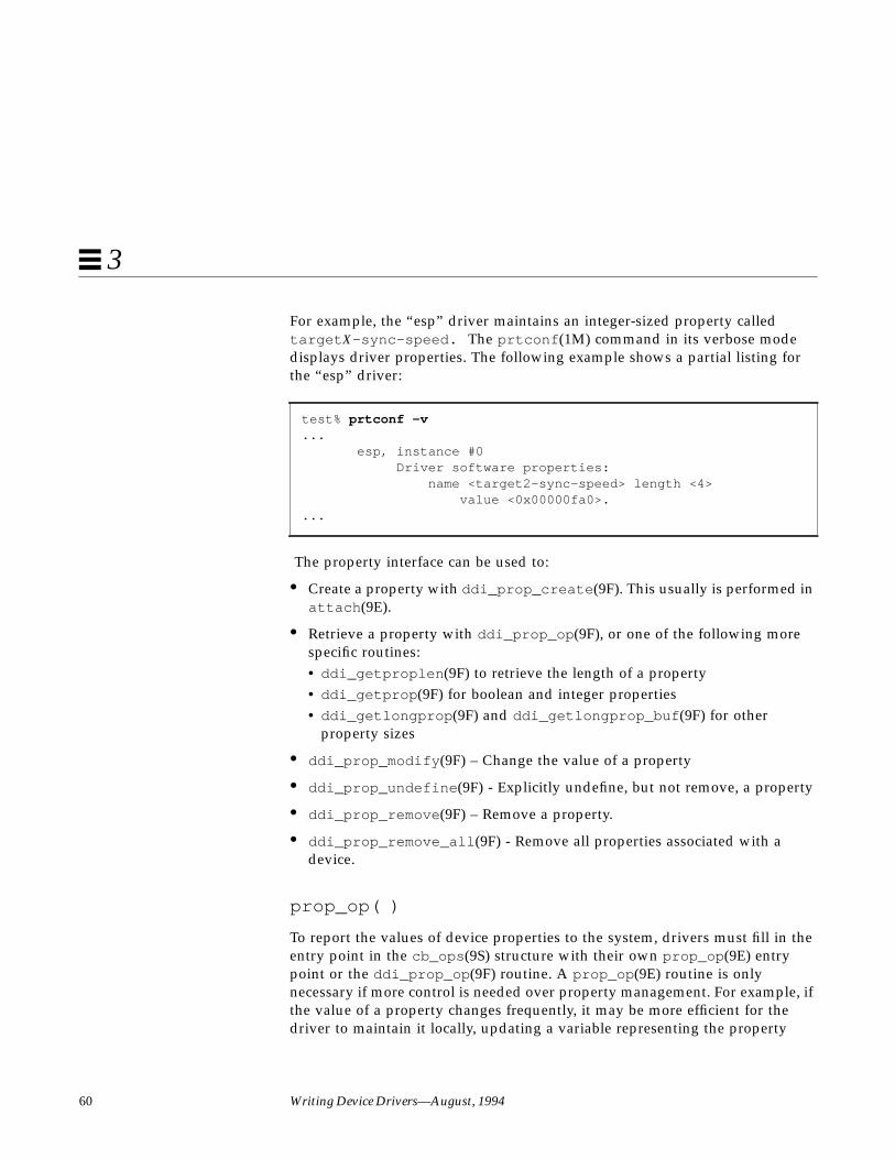
60 Writing Device Drivers—August, 1994
3
For example, the “esp” driver maintains an integer-sized property calledtarget X-sync-speed. The prtconf (1M) command in its verbose modedisplays driver properties. The following example shows a partial listing forthe “esp” driver:
The property interface can be used to:
• Create a property with ddi_prop_create (9F). This usually is performed inattach (9E).
• Retrieve a property with ddi_prop_op (9F), or one of the following morespecific routines:• ddi_getproplen (9F) to retrieve the length of a property• ddi_getprop (9F) for boolean and integer properties• ddi_getlongprop (9F) and ddi_getlongprop_buf (9F) for other
property sizes
• ddi_prop_modify (9F) – Change the value of a property
• ddi_prop_undefine (9F) - Explicitly undefine, but not remove, a property
• ddi_prop_remove (9F) – Remove a property.
• ddi_prop_remove_all (9F) - Remove all properties associated with adevice.
prop_op( )
To report the values of device properties to the system, drivers must fill in theentry point in the cb_ops (9S) structure with their own prop_op (9E) entrypoint or the ddi_prop_op (9F) routine. A prop_op (9E) routine is onlynecessary if more control is needed over property management. For example, ifthe value of a property changes frequently, it may be more efficient for thedriver to maintain it locally, updating a variable representing the property
test% prtconf -v... esp, instance #0 Driver software properties: name <target2-sync-speed> length <4> value <0x00000fa0>....

Overview of SunOS Device Drivers 61
3
value whenever it changes. If a caller requests the value of the property, thedriver’s prop_op (9E) modifies the property using ddi_prop_modify (9F) andthen calls ddi_prop_op (9F) to retrieve it.
Providing a prop_op (9E) entry point does not mean that the driver mustmanage all properties locally. If a property is modified dynamically, it shouldbe maintained by the driver in prop_op (9E). If a property is static (set onlyonce), it is easier for the driver to use ddi_prop_create (9F) to create it andallow ddi_prop_op (9F) to retrieve it. The prop_op (9E) entry point would justintercept some property requests and pass all others to ddi_prop_op (9F).Here is the prop_op (9E) prototype:
int xxprop_op(dev_t dev, dev_info_t *dip,ddi_prop_op_t prop_op, int flags, char *name,caddr_t valuep, int *lengthp);
This section describes a simple implementation of the prop_op (9E) routinethat intercepts property requests then uses the existing software propertyroutines to update property values. For a complete description of all theparameters to prop_op (9E), see the manual page.
In Code Example 3-3, the prop_op (9E) intercepts requests for the nblocksproperty. The driver updates a variable in the state structure whenever theproperty changes but only updates the property when a request is made. Itthen uses the system routine ddi_prop_op (9F) to get the new value. If theproperty request is not specific to a device, the driver does not intercept therequest. This is indicated when the value of the dev parameter is equal toDDI_DEV_T_ANY (the wildcard device number).
State StructureThis section adds the following field to the state structure. See “State Structure”on page 57 for more information.
int nblocks; /* number of blocks in block device */
Code Example 3-3 prop_op (9E) routine
static intxxprop_op(dev_t dev, dev_info_t *dip, ddi_prop_op_t prop_op,
int flags, char *name, caddr_t valuep, int *lengthp){
int instance;struct xxstate *xsp;

62 Writing Device Drivers—August, 1994
3
if (dev == DDI_DEV_T_ANY)goto skip;
instance = getminor(dev);xsp = ddi_get_soft_state(statep, instance);if (xsp == NULL)
return (DDI_PROP_NOTFOUND);
if (strcmp(name, "nblocks") == 0) {ddi_prop_modify(dev, dip, “nblocks”, flags,
&xsp->nblocks, sizeof(int));}other cases
skip:return (ddi_prop_op(dev, dip, prop_op, flags, name,
valuep, lengthp));}
Driver LayoutThis section suggests a structure for device drivers. The following sectionsdescribe the example driver layout in detail.
The code for a device driver is usually divided into the following files:
• headers (.h files)
• source files (.c files)
• possibly a configuration file (.conf file)
Note – This is a suggested layout only. It is not required, as only the final objectmodule matters to the system.
Header Files
Header files define data structures specific to the device (such as a structurerepresenting the device registers), data structures defined by the driver formaintaining state information, defined constants (such as those representingthe bits of the device registers), and macros (such as those defining the staticmapping between the minor device number and the instance number).

Overview of SunOS Device Drivers 63
3
Some of this information, such as the state structure, may only be needed bythe device driver. This information should go in private headers. These headerfiles are only included by the device driver itself.
Any information that an application might require, such as the I/O controlcommands, should be in public header files. These are included by the driverand any applications that need information about the device.
There is no standard for naming private and public files. One possibleconvention is to name the private header file xximpl.h and the public headerfile xxio.h . Code Example 3-4, and Code Example 3-5 show the layout ofthese headers.
Code Example 3-4 xximpl.h Header File
/* * xximpl.h */
struct device_reg { /* fields... */
};
/* * #define bits of the device registers... */
struct xxstate {/* fields */
};
/* * related #define statements */
Code Example 3-5 xxio.h Header File
/* * xxio.h */
struct xxioctlreq {/* fields */
};
/* * etc. */

64 Writing Device Drivers—August, 1994
3
#define XXIOC (‘b’ << 8)#define XXIOCTL_1 (XXIOC | 1) /* description */#define XXIOCTL_2 (XXIOC | 2) /* description */
xx.c Files
A.c file for a device driver contains the data declarations and the code for theentry points of the driver. It contains the #include statements the driverneeds, declares extern references, declares local data, sets up the cb_ops anddev_ops structures, declares and initializes the module configuration section,makes any other necessary declarations, and defines the driver entry points.The following sections describe these driver components. Code Example 3-6shows the layout of an xx.c file:
Code Example 3-6 xx.c File
/* * xx.c */
#include "xximpl.h"#include "xxio.h"#include <sys/ddi.h> /* must include these two files */#include <sys/sunddi.h> /* and they must be the last system */
/* includes */
/* * Forward declaration of entry points */
/* * static declarations of cb_ops entry point functions... */static struct cb_ops xx_cb_ops = {
/* * set cb_ops fields */
};
/* * static declarations of dev_ops entry point functions... */static struct dev_ops xx_ops = {
/*

Overview of SunOS Device Drivers 65
3
* set dev_ops fields */
};
/* * declare and initialize the module configuration section... */static struct modldrv modldrv = {
/* * set modldrv fields */
};
static struct modlinkage modlinkage = {/* * set modlinkage fields */
};
int_init(void){
/* definition */}
int_info(struct modinfo *modinfop){
/* definition */}
int_fini(void){
/* definition */}
static intxxidentify(dev_info_t *dip){
/* definition */}
static intxxprobe(dev_info_t *dip){
/* definition */}

66 Writing Device Drivers—August, 1994
3
static intxxattach(dev_info_t *dip, ddi_attach_cmd_t cmd){
/* definition */}
static intxxdetach(dev_info_t *dip, ddi_detach_cmd_t cmd){
/* definition */}
static intxxgetinfo(dev_info_t *dip, ddi_info_cmd_t cmd, void *arg, void **result){
/* definition */}
static intxxopen(dev_t *devp, int flag, int otyp, cred_t *credp){
/* definition */}
static intxxclose(dev_t dev, int flag, int otyp, cred_t *credp){
/* definition */}
static intxxstrategy(struct buf *bp){
/* definition */}
/* for character-oriented devices */static intxxread(dev_t dev, struct uio *uiop, cred_t *credp){
/* definition */}
static intxxwrite(dev_t dev, struct uio *uiop, cred_t *credp){
/* definition */}
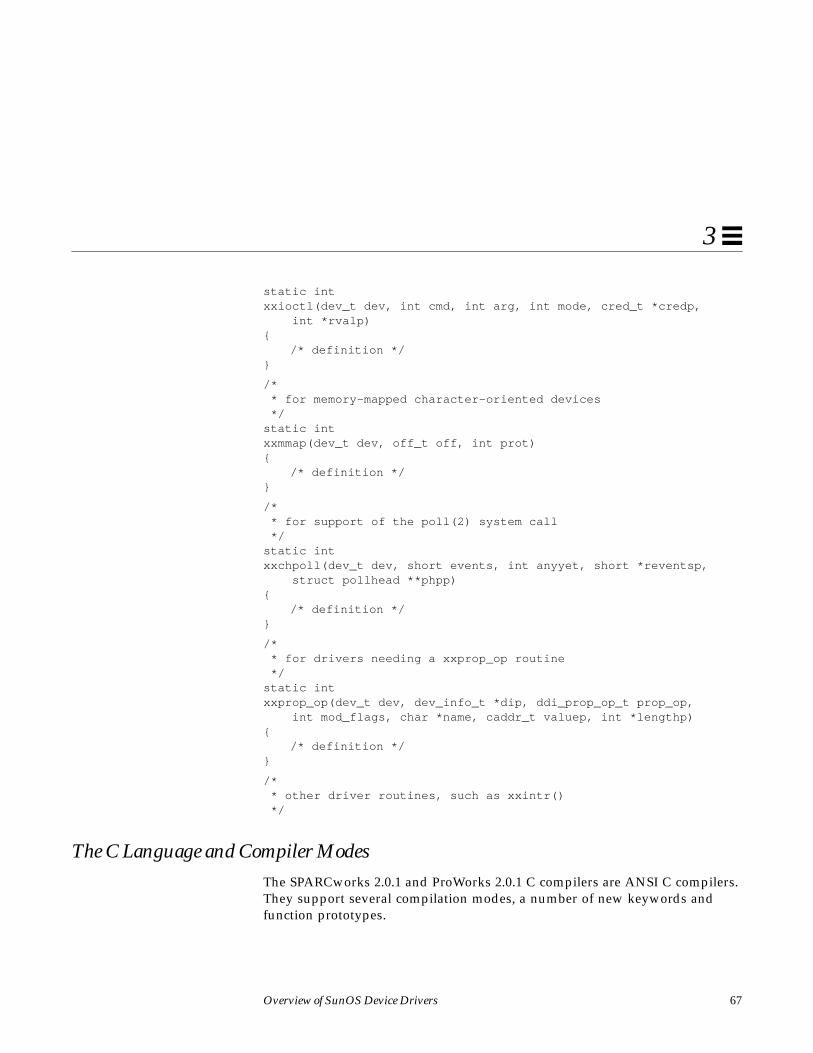
Overview of SunOS Device Drivers 67
3
static intxxioctl(dev_t dev, int cmd, int arg, int mode, cred_t *credp, int *rvalp){
/* definition */}
/* * for memory-mapped character-oriented devices */static intxxmmap(dev_t dev, off_t off, int prot){
/* definition */}
/* * for support of the poll(2) system call */static intxxchpoll(dev_t dev, short events, int anyyet, short *reventsp, struct pollhead **phpp){
/* definition */}
/* * for drivers needing a xxprop_op routine */static intxxprop_op(dev_t dev, dev_info_t *dip, ddi_prop_op_t prop_op, int mod_flags, char *name, caddr_t valuep, int *lengthp){
/* definition */}
/* * other driver routines, such as xxintr() */
The C Language and Compiler ModesThe SPARCworks 2.0.1 and ProWorks 2.0.1 C compilers are ANSI C compilers.They support several compilation modes, a number of new keywords andfunction prototypes.

68 Writing Device Drivers—August, 1994
3
Compiler Modes
The following compiler modes are of interest to driver writers:
-Xt (Transition Mode)
This mode accepts ANSI C and Sun C compatibility extensions. In case of aconflict between ANSI and Sun C, a warning is issued and Sun C semantics areused. This is the default mode.
-Xa (ANSI C Mode)
This mode accepts ANSI C and Sun C compatibility extensions. In case of aconflict between ANSI and Sun C, the compiler issues a warning and usesANSI C interpretations. This will be the default mode in the future.
Function Prototypes
Function prototypes specify the following information to the compiler:
• The type returned by the function• The number of the arguments to the function• The type of each argument
This allows the compiler to do more type checking and also to promote thetypes of the parameters to the type expected by the function. For example, ifthe compiler knows a function takes a pointer, casting NULL to that pointertype is no longer necessary. Prototypes are provided for most Solaris 2.xDDI/DKI functions, provided the driver includes the proper header file(documented in the manual page for the function).
New Keywords
There are a few new keywords available in ANSI C. The following keywordsare of interest to driver writers:
const
The const keyword can be used to define constants instead of using #define :

Overview of SunOS Device Drivers 69
3
const int count=5;
However, it is most useful when combined with function prototypes. Routinesthat should not be modifying parameters can define the parameters asconstants, and the compiler will then give errors if the parameter is modified.Since C passes parameters by value, most parameters don’t need to be declaredas constants. If the parameter is a pointer, though, it can be declared to point toa constant object:
int strlen(const char *s){
...}
Any attempt to change the string by strlen () is an error, and the compilerwill now catch it.
volatile
The correct use of volatile is necessary to prevent elusive bugs. It instructsthe compiler to use exact semantics for the declared objects—in particular, donot optimize away or reorder accesses to the object. There are two instanceswhere device drivers must use the volatile qualifier:
1. When data refers to an external hardware device register (memory that hasside effects other than just storage)
2. When data refers to global memory that is accessible by more than onethread, is not protected by locks, and therefore is relying on the sequencingof memory accesses
In general, drivers should not qualify a variable as volatile if it is merelyaccessible by more than one thread and protected from conflicting access bysynchronization routines.
The following is an example of the first use. There are two writes to a devicerequired to begin a transfer:
struct device_reg *regp;
regp->csr = ENABLE_INTERRUPTS;regp->csr = START_TRANSFER;
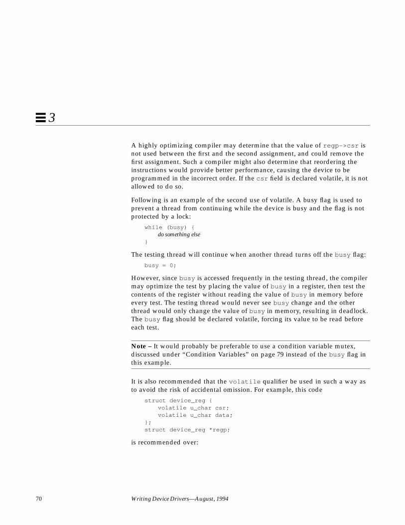
70 Writing Device Drivers—August, 1994
3
A highly optimizing compiler may determine that the value of regp->csr isnot used between the first and the second assignment, and could remove thefirst assignment. Such a compiler might also determine that reordering theinstructions would provide better performance, causing the device to beprogrammed in the incorrect order. If the csr field is declared volatile, it is notallowed to do so.
Following is an example of the second use of volatile. A busy flag is used toprevent a thread from continuing while the device is busy and the flag is notprotected by a lock:
while (busy) {do something else
}
The testing thread will continue when another thread turns off the busy flag:
busy = 0;
However, since busy is accessed frequently in the testing thread, the compilermay optimize the test by placing the value of busy in a register, then test thecontents of the register without reading the value of busy in memory beforeevery test. The testing thread would never see busy change and the otherthread would only change the value of busy in memory, resulting in deadlock.The busy flag should be declared volatile, forcing its value to be read beforeeach test.
Note – It would probably be preferable to use a condition variable mutex,discussed under “Condition Variables” on page 79 instead of the busy flag inthis example.
It is also recommended that the volatile qualifier be used in such a way asto avoid the risk of accidental omission. For example, this code
struct device_reg {volatile u_char csr;volatile u_char data;
};struct device_reg *regp;
is recommended over:
Overview of SunOS Device Drivers 71
3
struct device_reg {u_char csr;u_char data;
};volatile struct device_reg *regp;
Although the two examples are functionally equivalent, the second onerequires the writer to ensure that volatile is used in every declaration oftype struct device_reg . The first example results in the data being treatedas volatile in all declarations and is therefore preferred.

72 Writing Device Drivers—August, 1994
3

73
Multithreading 4
This chapter describes the locking primitives and thread synchronizationmechanisms of the SunOS multithreaded kernel.
ThreadsA thread of control, or thread, is a sequence of instructions executed within aprogram. A thread can share data and code with other threads and can runconcurrently with other threads. There are two kinds of threads: user threads andkernel threads. See Multithreaded Programming Guide for more information onthreads.
User Threads
Each process in the SunOS operating system has an address space that containsone or more lightweight processes (LWPs), each of which in turn runs one ormore user threads. Figure 4-1 shows the relationship between threads, LWPsand processes. An LWP schedules its user threads and runs one user thread ata time, though multiple LWPs may run concurrently. User threads are handledin user space.
The LWP is the interface between user threads and the kernel. The LWP can bethought of as virtual CPU that schedules user thread execution. When a userthread issues a system call, the LWP running the thread calls into the kerneland remains bound to the thread at least until the system call completes. When
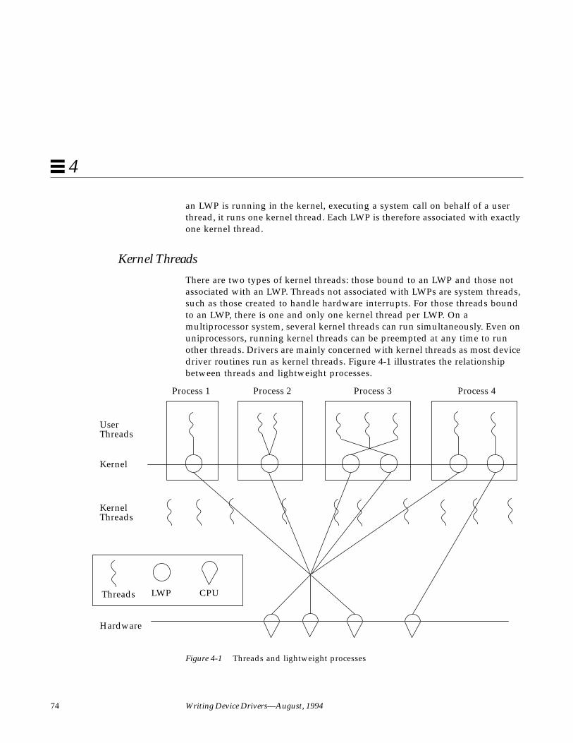
74 Writing Device Drivers—August, 1994
4
an LWP is running in the kernel, executing a system call on behalf of a userthread, it runs one kernel thread. Each LWP is therefore associated with exactlyone kernel thread.
Kernel Threads
There are two types of kernel threads: those bound to an LWP and those notassociated with an LWP. Threads not associated with LWPs are system threads,such as those created to handle hardware interrupts. For those threads boundto an LWP, there is one and only one kernel thread per LWP. On amultiprocessor system, several kernel threads can run simultaneously. Even onuniprocessors, running kernel threads can be preempted at any time to runother threads. Drivers are mainly concerned with kernel threads as most devicedriver routines run as kernel threads. Figure 4-1 illustrates the relationshipbetween threads and lightweight processes.
Figure 4-1 Threads and lightweight processes
UserThreads
Kernel
KernelThreads
Hardware
Threads LWP CPU
Process 1 Process 2 Process 3 Process 4
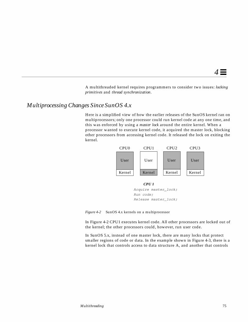
Multithreading 75
4
A multithreaded kernel requires programmers to consider two issues: lockingprimitives and thread synchronization.
Multiprocessing Changes Since SunOS 4.xHere is a simplified view of how the earlier releases of the SunOS kernel ran onmultiprocessors; only one processor could run kernel code at any one time, andthis was enforced by using a master lock around the entire kernel. When aprocessor wanted to execute kernel code, it acquired the master lock, blockingother processors from accessing kernel code. It released the lock on exiting thekernel.
Figure 4-2 SunOS 4.x kernels on a multiprocessor
In Figure 4-2 CPU1 executes kernel code. All other processors are locked out ofthe kernel; the other processors could, however, run user code.
In SunOS 5.x, instead of one master lock, there are many locks that protectsmaller regions of code or data. In the example shown in Figure 4-3, there is akernel lock that controls access to data structure A, and another that controls
User
Kernel
User
Kernel
User
Kernel
User
Kernel
CPU0 CPU1 CPU2 CPU3
CPU 1Acquire master_lock;
Release master_lock;Run code;

76 Writing Device Drivers—August, 1994
4
access to data structure B. Using these locks, only one processor at a time canbe executing code dealing with data structure A, but another could beaccessing data within structure B. This allows a greater degree of concurrency.
Figure 4-3 SunOS 5.x on a multiprocessor
In Figure 4-3 CPU1 and CPU3 are executing kernel code simultaneously.
Locking PrimitivesIn traditional UNIX systems, any section of kernel code runs until it explicitlygives up the processor by calling sleep() or is interrupted by hardware. Thisis not true in SunOS 5.x! A kernel thread can be preempted at any time to runanother thread. Since all kernel threads share kernel address space, and oftenneed to read and modify the same data, the kernel provides a number oflocking primitives to prevent threads from corrupting shared data. Thesemechanisms include mutual exclusion locks, readers/writer locks and semaphores.
Storage Classes of Driver Data
The storage class of data is a guide to whether the driver may need to takeexplicit steps to control access to the data.
Automatic (Stack) Data
Since every thread has a private stack, drivers never need to lock automaticvariables.
User
Kernel
User
Kernel
User
Kernel
User
Kernel
CPU0 CPU1 CPU2 CPU3
CPU 1 CPU 3Acquire lock_A;
Modify A;Release lock_A;
Acquire lock_B;Modify B;
Release lock_B;
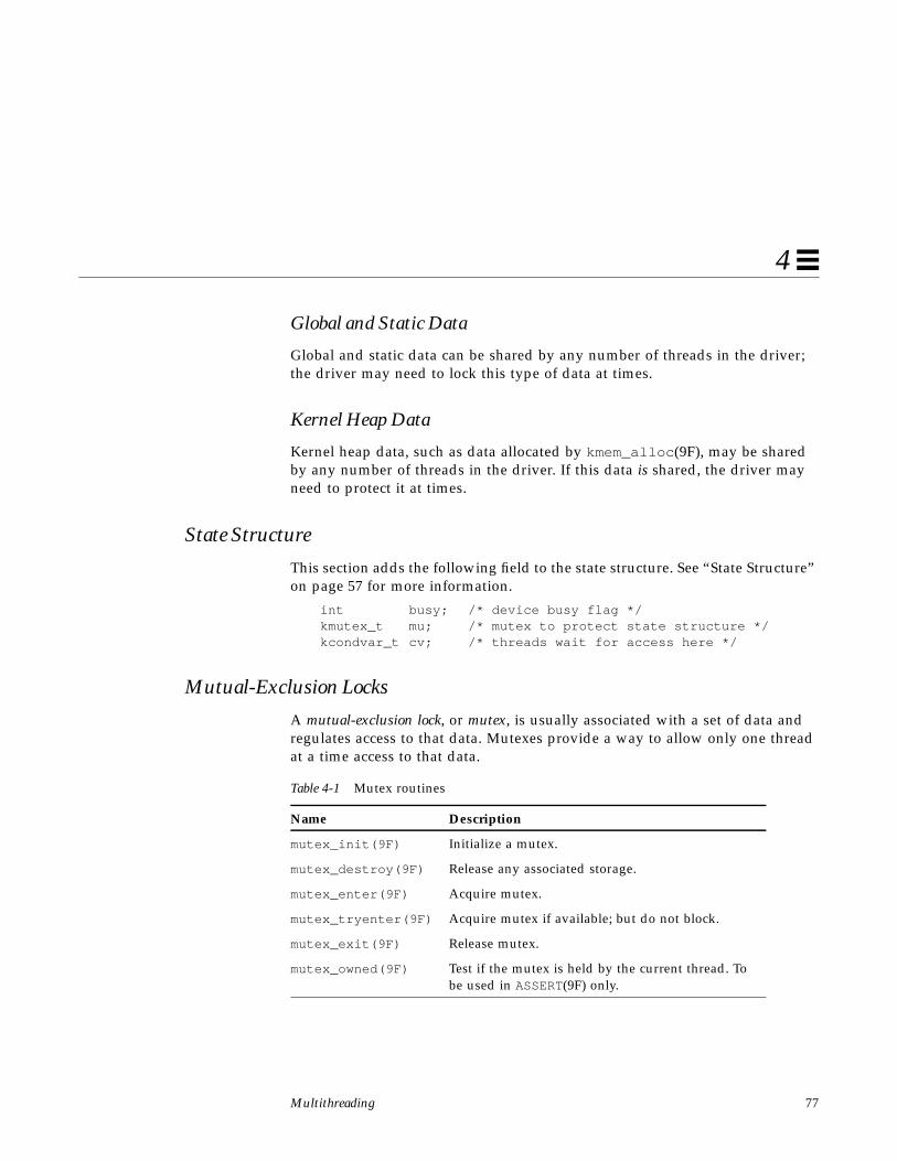
Multithreading 77
4
Global and Static Data
Global and static data can be shared by any number of threads in the driver;the driver may need to lock this type of data at times.
Kernel Heap Data
Kernel heap data, such as data allocated by kmem_alloc (9F), may be sharedby any number of threads in the driver. If this data is shared, the driver mayneed to protect it at times.
State Structure
This section adds the following field to the state structure. See “State Structure”on page 57 for more information.
int busy; /* device busy flag */kmutex_t mu; /* mutex to protect state structure */kcondvar_t cv; /* threads wait for access here */
Mutual-Exclusion Locks
A mutual-exclusion lock, or mutex, is usually associated with a set of data andregulates access to that data. Mutexes provide a way to allow only one threadat a time access to that data.
Table 4-1 Mutex routines
Name Description
mutex_init(9F) Initialize a mutex.
mutex_destroy(9F) Release any associated storage.
mutex_enter(9F) Acquire mutex.
mutex_tryenter(9F) Acquire mutex if available; but do not block.
mutex_exit(9F) Release mutex.
mutex_owned(9F) Test if the mutex is held by the current thread. Tobe used in ASSERT(9F) only.

78 Writing Device Drivers—August, 1994
4
Setting Up Mutexes
Device drivers usually allocate a mutex for each driver data structure. Themutex is typically a field in the structure and is of type kmutex_t .mutex_init (9F) is called to prepare the mutex for use. This is usually done atattach (9E) time for per-device mutexes and _init (9E) time for global drivermutexes.
For example,
struct xxstate *xsp;
...mutex_init(&xsp->mu, “xx mutex”, MUTEX_DRIVER, NULL);...
For a more complete example of mutex initialization see Chapter 5,“Autoconfiguration.”
The driver must destroy the mutex with mutex_destroy(9F) before beingunloaded. This is usually done at detach (9E) time for per-device mutexes and_fini (9E) time for global driver mutexes.
Using Mutexes
Every section of the driver code that needs to read or write the shared datastructure must do the following:
• Acquire the mutex.• Access the data.• Release the mutex
For example, to protect access to the busy flag in the state structure:
...mutex_enter(&xsp->mu);xsp->busy = 0;mutex_exit(&xsp->mu);....
The scope of a mutex—the data it protects—is entirely up to the programmer.A mutex protects some particular data structure because the programmer choosesto do so and uses it accordingly. A mutex protects a data structure only if everycode path that accesses the data structure does so while holding the mutex. Foradditional guidelines on using mutexes see Appendix B, “Advanced Topics.”

Multithreading 79
4
Readers/Writer Locks
A readers/writer lock regulates access to a set of data. The readers/writer lock isso called because many threads can hold the lock simultaneously for reading,but only one thread can hold it for writing.
Most device drivers do not use readers/writer locks. These locks are slowerthan mutexes and provide a performance gain only when protecting data thatis not frequently written but is commonly read by many concurrent threads. Inthis case, contention for a mutex could become a bottleneck, so using areaders/writer lock might be more efficient. See rwlock (9F) for moreinformation.
Semaphores
Counting semaphores are available as an alternative primitive for managingthreads within device drivers. See semaphore (9F) for more information.
Thread SynchronizationIn addition to protecting shared data, drivers often need to synchronizeexecution among multiple threads.
Condition Variables
Condition variables are a standard form of thread synchronization. They aredesigned to be used with mutexes. The associated mutex is used to ensure thata condition can be checked atomically, and that the thread can block on theassociated condition variable without missing either a change to the conditionor a signal that the condition has changed. Condition variables must beinitialized by calling cv_init (9F) and must be destroyed by callingcv_destroy (9F).
Note – Condition variable routines are approximately equivalent to theroutines sleep() and wakeup() used in SunOS 4.x.

80 Writing Device Drivers—August, 1994
4
Table 4-2 lists the condvar (9F) interfaces. The four wait routines –cv_wait (9F), cv_timedwait (9F), cv_wait_sig (9F), andcv_timedwait_sig (9F) – take a pointer to a mutex as an argument.
Initializing Condition Variables
Declare a condition variable (type kcondvar_t ) for each condition. Usually,this is done in the driver’s soft-state structure. Use cv_init (9F) to initializeeach one. Similar to mutexes, condition variables are usually initialized atattach (9E) time. For example,
...cv_init(&xsp->cv, “xx cv”, CV_DRIVER, NULL);...
For a more complete example of condition variable initialization see Chapter 5,“Autoconfiguration.”
Using Condition Variables
On the code path waiting for the condition take the following steps:
• Acquire the mutex guarding the condition.• Test the condition.
Table 4-2 Condition variable routines
Name Description
cv_init(9F) Initialize a condition variable.
cv_destroy(9F) Destroy a condition variable.
cv_wait(9F) Wait for condition.
cv_timedwait(9F) Wait for condition or timeout.
cv_wait_sig(9F) Wait for condition or return zero on receipt of a signal.
cv_timedwait_sig(9F) Wait for condition or timeout or signal.
cv_signal(9F) Signal one thread waiting on the condition variable
cv_broadcast(9F) Signal all threads waiting on the condition variable
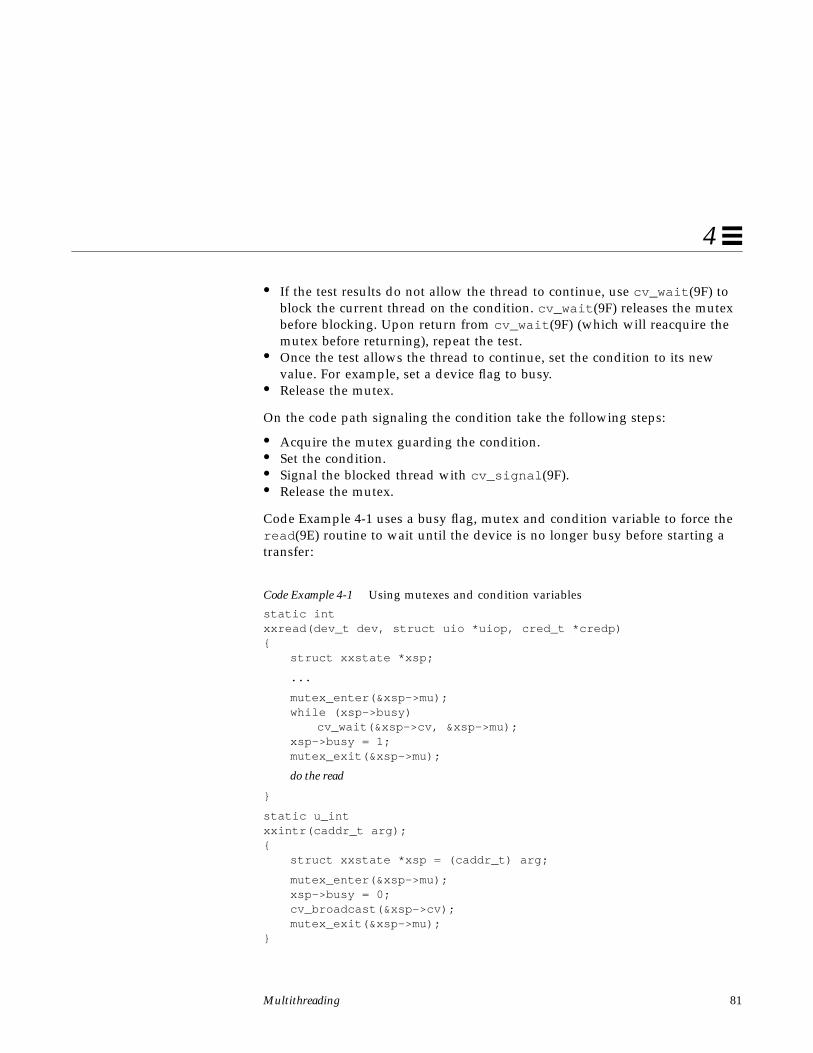
Multithreading 81
4
• If the test results do not allow the thread to continue, use cv_wait (9F) toblock the current thread on the condition. cv_wait (9F) releases the mutexbefore blocking. Upon return from cv_wait (9F) (which will reacquire themutex before returning), repeat the test.
• Once the test allows the thread to continue, set the condition to its newvalue. For example, set a device flag to busy.
• Release the mutex.
On the code path signaling the condition take the following steps:
• Acquire the mutex guarding the condition.• Set the condition.• Signal the blocked thread with cv_signal (9F).• Release the mutex.
Code Example 4-1 uses a busy flag, mutex and condition variable to force theread (9E) routine to wait until the device is no longer busy before starting atransfer:
Code Example 4-1 Using mutexes and condition variables
static intxxread(dev_t dev, struct uio *uiop, cred_t *credp){
struct xxstate *xsp;
...
mutex_enter(&xsp->mu);while (xsp->busy)
cv_wait(&xsp->cv, &xsp->mu);xsp->busy = 1;mutex_exit(&xsp->mu);
do the read
}
static u_intxxintr(caddr_t arg);{
struct xxstate *xsp = (caddr_t) arg;
mutex_enter(&xsp->mu);xsp->busy = 0;cv_broadcast(&xsp->cv);mutex_exit(&xsp->mu);
}
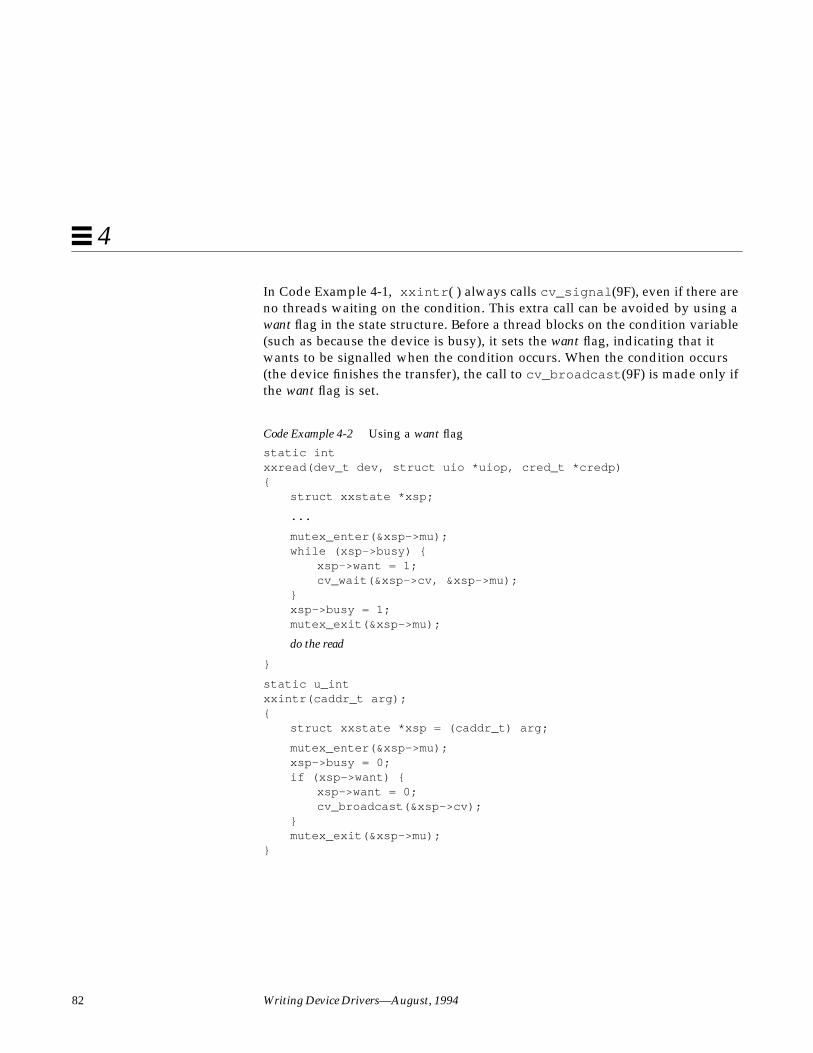
82 Writing Device Drivers—August, 1994
4
In Code Example 4-1, xxintr ( ) always calls cv_signal (9F), even if there areno threads waiting on the condition. This extra call can be avoided by using awant flag in the state structure. Before a thread blocks on the condition variable(such as because the device is busy), it sets the want flag, indicating that itwants to be signalled when the condition occurs. When the condition occurs(the device finishes the transfer), the call to cv_broadcast (9F) is made only ifthe want flag is set.
Code Example 4-2 Using a want flag
static intxxread(dev_t dev, struct uio *uiop, cred_t *credp){
struct xxstate *xsp;
...
mutex_enter(&xsp->mu);while (xsp->busy) {
xsp->want = 1;cv_wait(&xsp->cv, &xsp->mu);
}xsp->busy = 1;mutex_exit(&xsp->mu);
do the read
}
static u_intxxintr(caddr_t arg);{
struct xxstate *xsp = (caddr_t) arg;
mutex_enter(&xsp->mu);xsp->busy = 0;if (xsp->want) {
xsp->want = 0;cv_broadcast(&xsp->cv);
}mutex_exit(&xsp->mu);
}
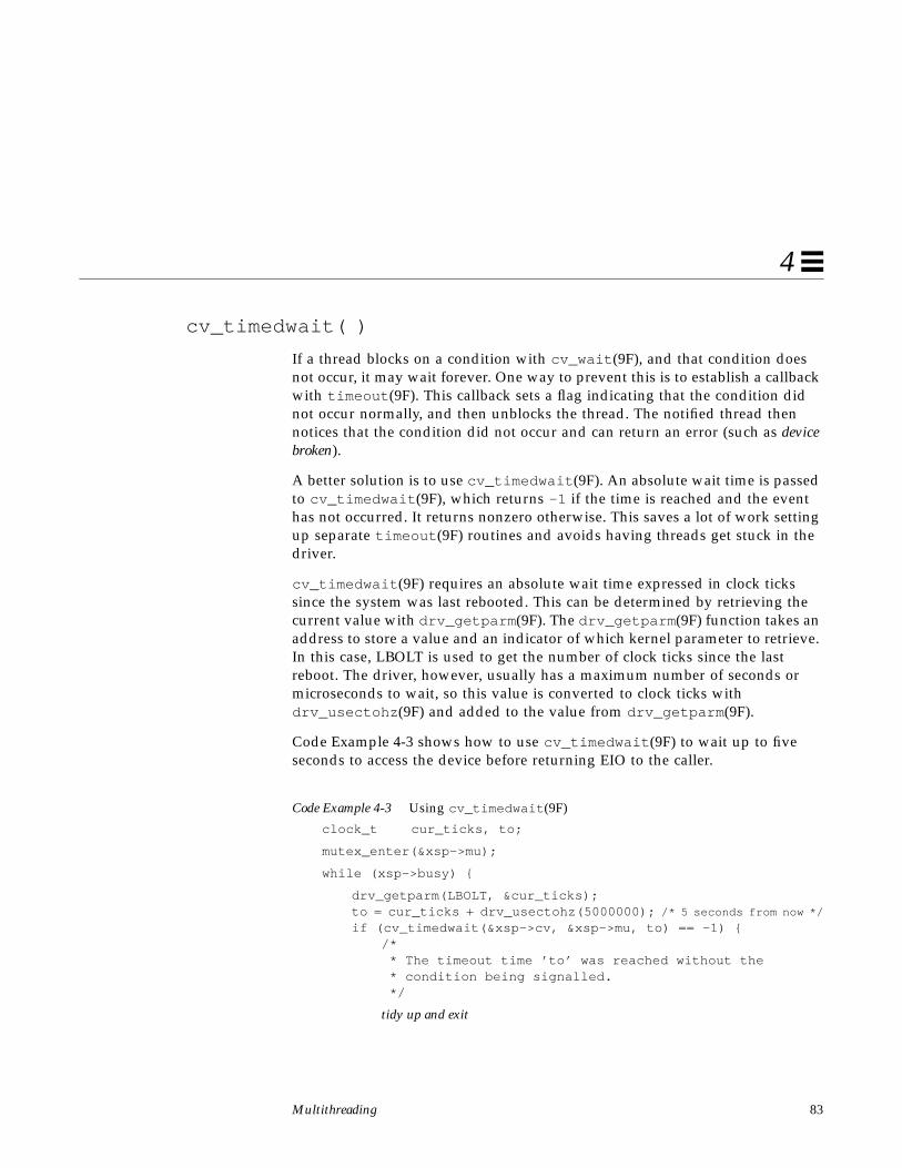
Multithreading 83
4
cv_timedwait( )
If a thread blocks on a condition with cv_wait (9F), and that condition doesnot occur, it may wait forever. One way to prevent this is to establish a callbackwith timeout (9F). This callback sets a flag indicating that the condition didnot occur normally, and then unblocks the thread. The notified thread thennotices that the condition did not occur and can return an error (such as devicebroken).
A better solution is to use cv_timedwait (9F). An absolute wait time is passedto cv_timedwait (9F), which returns -1 if the time is reached and the eventhas not occurred. It returns nonzero otherwise. This saves a lot of work settingup separate timeout (9F) routines and avoids having threads get stuck in thedriver.
cv_timedwait (9F) requires an absolute wait time expressed in clock tickssince the system was last rebooted. This can be determined by retrieving thecurrent value with drv_getparm (9F). The drv_getparm (9F) function takes anaddress to store a value and an indicator of which kernel parameter to retrieve.In this case, LBOLT is used to get the number of clock ticks since the lastreboot. The driver, however, usually has a maximum number of seconds ormicroseconds to wait, so this value is converted to clock ticks withdrv_usectohz (9F) and added to the value from drv_getparm (9F).
Code Example 4-3 shows how to use cv_timedwait (9F) to wait up to fiveseconds to access the device before returning EIO to the caller.
Code Example 4-3 Using cv_timedwait (9F)
clock_t cur_ticks, to;
mutex_enter(&xsp->mu);
while (xsp->busy) {
drv_getparm(LBOLT, &cur_ticks);to = cur_ticks + drv_usectohz(5000000); /* 5 seconds from now */
if (cv_timedwait(&xsp->cv, &xsp->mu, to) == -1) {/* * The timeout time ’to’ was reached without the * condition being signalled. */
tidy up and exit

84 Writing Device Drivers—August, 1994
4
mutex_exit(&xsp->mu);return (EIO);
}}
xsp->busy = 1;mutex_exit(&xsp->mu);
cv_wait_sig( )
There is always the possibility that either the driver accidentally waits for acondition that will never occur (as described in “cv_timedwait( )” on page 81),or that the condition will not happen for a long time. In either case, the usermay want to abort the thread by sending it a signal. Whether the signal causesthe driver to wake up depends on the driver.
cv_wait_sig (9F) allows a signal to unblock the thread. This allows the userto break out of potentially long waits by sending a signal to the thread withkill (1) or by typing the interrupt character. cv_wait_sig (9F) returns zero ifit is returning because of a signal, or nonzero if the condition occurred.
Code Example 4-4 Using cv_wait_sig (9F)
mutex_enter(&xsp->mu);
while (xsp->busy) {if (cv_wait_sig(&xsp->cv, &xsp->mu) == 0) {
/* Signalled while waiting for the condition. */
tidy up and exit
mutex_exit(&xsp->mu);return (EINTR);
}}
xsp->busy = 1;mutex_exit(&xsp->mu);
cv_timedwait_sig( )
cv_timedwait_sig (9F) is similar to cv_timedwait (9F) andcv_wait_sig (9F), except that it returns -1 without the condition beingsignaled after a timeout has been reached, or 0 if a signal (for example,kill (2)) is sent to the thread.

Multithreading 85
4
For both cv_timedwait (9F) and cv_timedwait_sig (9F), time is measuredin absolute clock ticks since the last system reboot.
Choosing a Locking SchemeThe locking scheme for most device drivers should be kept straightforward.Using additional locks may allow more concurrency but increase overhead.Using fewer locks is cheaper but allows less concurrency. Generally, use onemutex per data structure, a condition variable for each event or condition thedriver must wait for, and a mutex for each major set of data global to thedriver. Avoid holding mutexes for long periods of time.
For more information on locking schemes, see Appendix B, “AdvancedTopics”. Also see Multithreaded Programming Guide for more detail onmultithreading operations.

86 Writing Device Drivers—August, 1994
4

87
Autoconfiguration 5
This chapter describes the support a driver must provide forautoconfiguration.
OverviewAutoconfiguration is the process of getting the driver’s code and static dataloaded into memory and registered with the system. Autoconfiguration alsoinvolves configuring (attaching) individual device instances that are controlledby the driver. These processes are discussed in more detail in “Loadable DriverInterface” on page 89 and “Device Configuration” on page 93. Theautoconfiguration process begins when the device is put into use.
State StructureThis section adds the following fields to the state structure. See “StateStructure” on page 57 for more information.
int instance;ddi_iblock_cookie_t iblock_cookie;ddi_idevice_cookie_t idevice_cookie;

88 Writing Device Drivers—August, 1994
5
Data StructuresFigure 5-1 shows an overview of the driver data structures that are accesseddirectly by the kernel for loading the driver, configuring devices, andproviding access to devices. The figure is divided into 3 sections; the first twoare discussed in this chapter. The third section is discussed in Chapter 8,“Drivers for Character Devices” and Chapter 9, “Drivers for Block Devices”.
Figure 5-1 shows the relationship between the autoconfiguration structures andthe driver entry points.
Figure 5-1 Autoconfiguration Data Structures
The structures in this diagram must be provided and initialized correctly forthe driver to load and for its routines to be called. If an operation is notsupported by the driver, the address of the routine nodev (9F) can be used to
_init(9E)
_info(9E)
_fini(9E)
mod_driveropsLoadable driver interface
Device configuration
getinfo(9E)
identify(9E)
dev_ops(9S)probe(9E)
attach(9E)
detach(9E)
Device accessopen(9E)
close(9E)
read(9E)
write(9E)
strategy(9E) prop_op(9E)
print(9E)
chpoll(9E)
ioctl(9E)
mmap(9E)
cb_ops(9S)
modlinkage(9S)
modldrv(9S)

Autoconfiguration 89
5
fill it in. If the driver supports the entry point, but does not need to doanything except return success, the address of the routine nulldev (9F) can beused.
Note – These structures should be initialized at compile-time. They should notbe accessed or changed by the driver at any other time.
modlinkage()
int ml_rev;void *ml_linkage[4];
The modlinkage (9S) structure is exported to the kernel when the driver isloaded. The ml_rev field indicates the revision number of the loadablemodule system, which should be set to MODREV_1. Drivers can only supportone module, so only the first element of ml_linkage should be set to theaddress of a modldrv (9S) structure. ml_linkage[1] should be set to NULL.
modldrv()
struct mod_ops *drv_modops;char *drv_linkinfo;struct dev_ops *drv_dev_ops;
This structure describes the module in more detail. The drv_modops fieldpoints to a structure describing the module operations, which is&mod_driverops for a device driver. The drv_linkinfo field is displayedby the modinfo (1M) command and should be an informative stringidentifying the device driver. The drv_dev_ops field points to the nextstructure in the chain, the dev_ops (9S) structure.
dev_ops()
int devo_rev;int devo_refcnt;int (*devo_getinfo)(dev_info_t *dip,ddi_info_cmd_t infocmd,
void *arg, void **result);int (*devo_identify)(dev_info_t *dip);int (*devo_probe)(dev_info_t *dip);int (*devo_attach)(dev_info_t *dip, ddi_attach_cmd_t cmd);int (*devo_detach)(dev_info_t *dip, ddi_detach_cmd_t cmd);
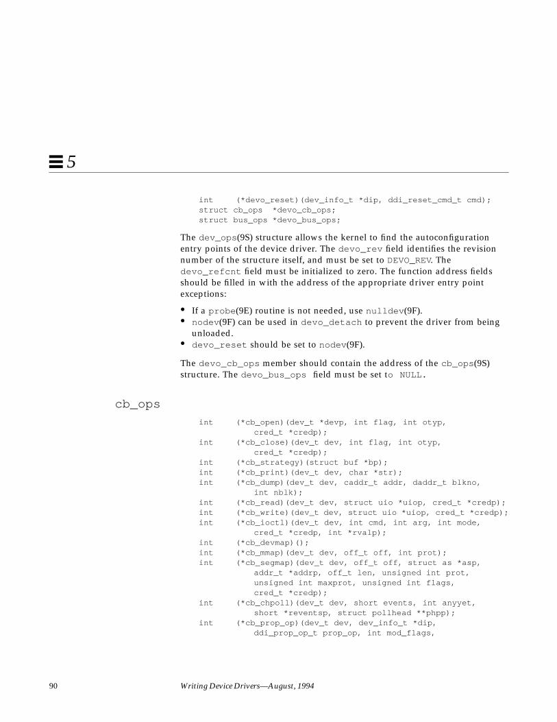
90 Writing Device Drivers—August, 1994
5
int (*devo_reset)(dev_info_t *dip, ddi_reset_cmd_t cmd);struct cb_ops *devo_cb_ops;struct bus_ops *devo_bus_ops;
The dev_ops (9S) structure allows the kernel to find the autoconfigurationentry points of the device driver. The devo_rev field identifies the revisionnumber of the structure itself, and must be set to DEVO_REV. Thedevo_refcnt field must be initialized to zero. The function address fieldsshould be filled in with the address of the appropriate driver entry pointexceptions:
• If a probe (9E) routine is not needed, use nulldev (9F).• nodev (9F) can be used in devo_detach to prevent the driver from being
unloaded.• devo_reset should be set to nodev (9F).
The devo_cb_ops member should contain the address of the cb_ops (9S)structure. The devo_bus_ops field must be set to NULL.
cb_ops
int (*cb_open)(dev_t *devp, int flag, int otyp,cred_t *credp);
int (*cb_close)(dev_t dev, int flag, int otyp,cred_t *credp);
int (*cb_strategy)(struct buf *bp);int (*cb_print)(dev_t dev, char *str);int (*cb_dump)(dev_t dev, caddr_t addr, daddr_t blkno,
int nblk);int (*cb_read)(dev_t dev, struct uio *uiop, cred_t *credp);int (*cb_write)(dev_t dev, struct uio *uiop, cred_t *credp);int (*cb_ioctl)(dev_t dev, int cmd, int arg, int mode,
cred_t *credp, int *rvalp);int (*cb_devmap)();int (*cb_mmap)(dev_t dev, off_t off, int prot);int (*cb_segmap)(dev_t dev, off_t off, struct as *asp,
addr_t *addrp, off_t len, unsigned int prot,unsigned int maxprot, unsigned int flags,cred_t *credp);
int (*cb_chpoll)(dev_t dev, short events, int anyyet,short *reventsp, struct pollhead **phpp);
int (*cb_prop_op)(dev_t dev, dev_info_t *dip,ddi_prop_op_t prop_op, int mod_flags,

Autoconfiguration 91
5
char *name, caddr_t valuep, int *length);struct streamtab *cb_str; /* STREAMS information */int cb_flag;
The cb_ops (9S) structure contains the entry points for the character and blockoperations of the device driver. Any entry points the driver does not supportshould be initialized to nodev (9F). For example, character device driversshould set all the block-only fields (such as cb_stategy to nodev (9F).
The cb_str field is used to determine if this is a STREAMS-based driver. Thedevice drivers discussed in this book are not STREAMS-based, so cb_str mustbe set to NULL. The cb_flag member indicates whether the driver is safe formultithreading (D_MP) and whether it is a new-style driver (D_NEW). Alldrivers are new-style drivers, and should properly handle the multithreadedenvironment, so cb_flag should be set to both (D_NEW | D_MP). If the driverproperly handles 64-bit offsets, it should also set the D_64BIT flag in thecb_flag field. This specifies that the driver will use the uio_loffset fieldof the uio (9S) structure.
Loadable Driver Interface
Device drivers must be dynamically loadable and should be unloadable to helpconserve memory resources. Drivers that can be unloaded are also easier to testand debug.
Each device driver has a section of code that defines a loadable interface. Thiscode section defines a static pointer for the soft state routines, the structuresdescribed in “Data Structures” on page 88 and the routines involved in loadingthe module.
Code Example 5-1 Loadable interface section
static void *statep; /* for soft state routines */
static struct cb_ops xx_cb_ops; /* forward reference */
static struct dev_ops xx_ops = {DEVO_REV,0,xxgetinfo,xxidentify,xxprobe,xxattach,xxdetach,nodev,

92 Writing Device Drivers—August, 1994
5
&xx_cb_ops,(struct bus_ops *) NULL
};
static struct modldrv modldrv = {&mod_driverops,"xx driver v1.0",&xx_ops
};
static struct modlinkage modlinkage = {MODREV_1,&modldrv,NULL
};
int_init(void){
int error;
ddi_soft_state_init(&statep, sizeof (struct xxstate),estimated number of instances);
further per-module initialization if necessaryerror = mod_install(&modlinkage);if (error) != 0 {
undo any per-module initialization done earlierddi_soft_state_fini(&statep);
}return (error);
}
int_fini(void){
int error;
error = mod_remove(&modlinkage);if (error == 0) {
release per-module resources if any were allocatedddi_soft_state_fini(&statep);
}return (error);
}
int_info(struct modinfo *modinfop){
return (mod_info(&modlinkage, modinfop));}
Autoconfiguration 93
5
Any one-time resource allocation or data initialization should be performedduring driver loading in _init (9E). For example, any mutexes global to thedriver should be initialized here. Do not, however, use _init (9E) to allocate orinitialize anything that has to do with a particular instance of the device.Per-instance initialization must be done in attach (9E). For example, if adriver for a printer can drive more than one printer at the same time, allocateresources specific to each printer instance in attach (9E).
Similarly, in _fini (9E), release only those resources allocated by _init (9E).
Note – Once _init (9E) has called mod_install (9F), none of the datastructures hanging off of the modlinkage (9S) structure should be changed bythe driver, as the system may make copies of them or change them.
Device ConfigurationEach driver must provide five entry points that are used by the kernel fordevice configuration. They are:
• identify (9E)• probe (9E)• attach (9E)• detach (9E)• getinfo (9E)
Every device driver must have an identify (9E), attach (9E) andgetinfo (9E) routine. probe (9E) is only required for non self-identifyingdevices. For self-identifying devices an explicit probe routine may be providedor nulldev (9F) may be specified in the dev_ops structure for the probe (9E)entry point.
identify( )
The system calls identify (9E) to find out whether the driver drives thedevice specified by dip .
Code Example 5-2 identify (9E) routine
static intxxidentify(dev_info_t *dip){

94 Writing Device Drivers—August, 1994
5
if (strcmp(ddi_get_name(dip), “xx”) == 0)return (DDI_IDENTIFIED);
elsereturn (DDI_NOT_IDENTIFIED);
}
If the device is known by several different names, identify (9E) should checkfor a match with each name before failing. The names must also have beenpassed with aliases to add_drv (1M) when the driver was installed. SeeChapter 12, “Loading and Unloading Drivers.”
identify (9E) should not maintain a device count, since the system does notguarantee that identify (9E) will be called for all device instances beforeattach (9E) is called for any device instance, nor does the system make anyguarantees about the number of times identify (9E) will be called for anygiven device.
Instance Numbers
In SunOS 4.x, drivers counted the calls to identify(9E) and used the currentvalue of this number as an instance number in a later call to attach() .However, drivers must not do this in Solaris 2.x. The system now assigns aninstance number to each device this number is derived in an implementation-specific manner from different properties for the different device types. Thefollowing properties are used to derive instance numbers:
The reg property is used for SBus, VMEbus, ISA, EISA, and MCA devices.Non-self-identifying device drivers provide this in the hardwareconfiguration file. See sbus (4), isa (4) and vme(4).
The target and lun properties are used for SCSI target devices. These areprovided in the hardware configuration file. See scsi (4).
The instance property is used for pseudo-devices. This is provided in thehardware configuration file. See pseudo (4).
The driver should retrieve the particular instance number that has beenassigned by calling ddi_get_instance (9F). See Code Example 5-4 on page 95for an example.

Autoconfiguration 95
5
Persistent Instances
Once an instance number has been assigned to a particular physical device bythe system, it stays the same even across reconfiguration and reboot. Becauseof this, instance numbers seen by a driver may not appear to be in consecutiveorder.
probe( )
For non-self-identifying devices (see “Device Identification” on page 14) thisentry point should determine whether the hardware device is present on thesystem and return:
DDI_PROBE_SUCCESS if the probe was successful
DDI_PROBE_FAILURE if the probe failed
DDI_PROBE_DONTCARE if the probe was unsuccessful, yet attach (9E)should still be called OR
DDI_PROBE_PARTIAL if the instance is not present now, but may bepresent in the future
For a given device instance, attach (9E) will not be called before probe (9E)has succeeded at least once on that device.
It is important that probe (9E) free all the resources it allocates, because it maybe called multiple times; however, attach (9E) will not necessarily be calledeven if probe (9E) succeeds.
For probe to determine whether the instance of the device is present,probe (9E) may need to do many of the things also commonly done byattach (9E). In particular, it may need to map the device registers.Code Example 5-3 is an example of probe (9E).
Code Example 5-3 probe (9E) routine
static intxxprobe(dev_info_t *dip){
int instance;volatile caddr_t reg_addr;
if (ddi_dev_is_sid(dip) == DDI_SUCCESS) /* no need to probe */return (DDI_PROBE_DONTCARE);

96 Writing Device Drivers—August, 1994
5
instance = ddi_get_instance(dip); /* assigned instance */
if (ddi_intr_hilevel(dip, inumber)) {cmn_err(CE_CONT,
“?xx driver does not support high level interrupts.”“ Probe failed.”);
return (DDI_PROBE_FAILURE);}
/* * Map device registers and try to contact device. */if (ddi_map_regs(dip, rnumber, ®_addr, offset, len) != 0)
return (DDI_PROBE_FAILURE);
if (ddi_peekc(dip, reg_addr, NULL) != DDI_SUCCESS)goto failed;
free allocated resources
ddi_unmap_regs(dip, rnumber, ®_addr, offset, len);
if ( device is present and ready for attach)return (DDI_PROBE_SUCCESS);
else if ( device is present but not ready for attach)return (DDI_PROBE_PARTIAL);
else /* device is not present */return (DDI_PROBE_FAILURE);
failed:free allocated resourcesddi_unmap_regs(dip, rnumber, ®_addr, offset, len);
return (DDI_PROBE_FAILURE);}
The string printed in the high-level interrupt case begins with a ‘?’ character.This causes the message to be printed only if the kernel was booted with theverbose (-v ) flag (See kernel (1M)). Otherwise the message only goes intothe message log, where it can be seen by running dmesg(1M).
Probing the device registers is device-specific. The driver probably has toperform a series of tests of the hardware to assure that the hardware is reallythere. The test criteria must be rigorous enough to avoid misidentifyingdevices. It may, for example, appear that the device is present when in fact it isnot, because a different device appears to behave like the expected device.
The ddi_peek (9F) and ddi_poke (9F) family of routines must be used toaccess the device registers, as they cope correctly with the faults that mayoccur if the access fails, for example, because the device is not there.
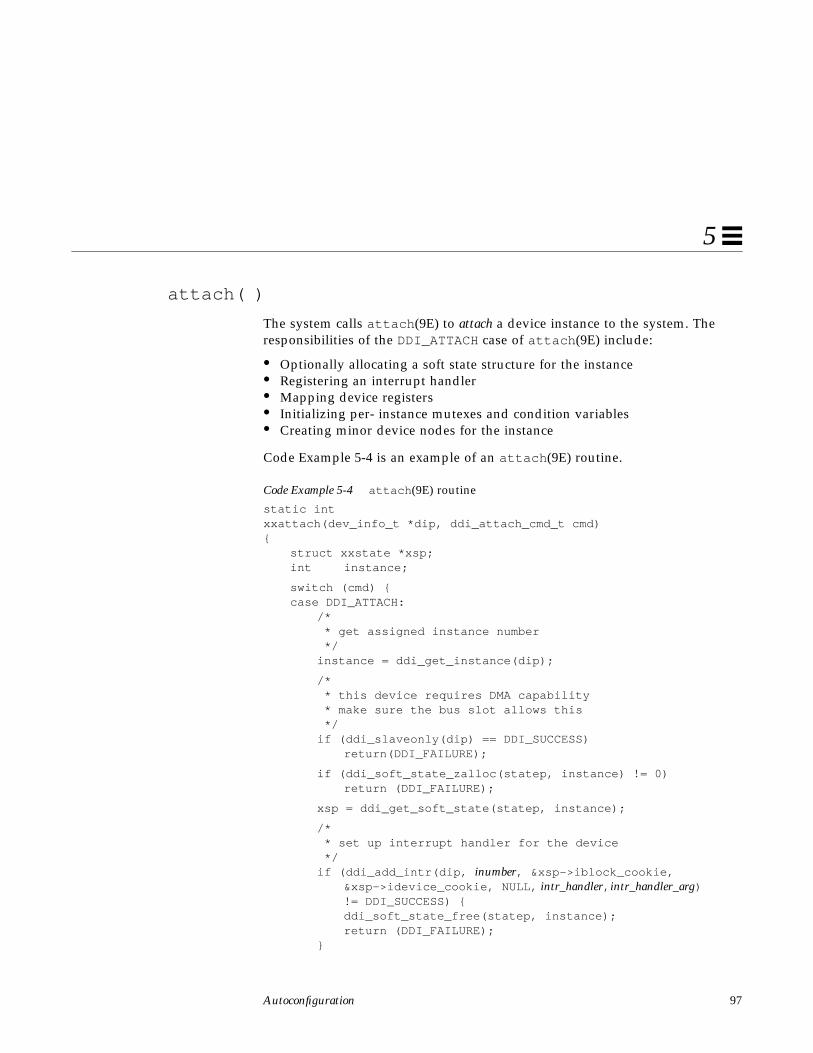
Autoconfiguration 97
5
attach( )
The system calls attach (9E) to attach a device instance to the system. Theresponsibilities of the DDI_ATTACH case of attach (9E) include:
• Optionally allocating a soft state structure for the instance• Registering an interrupt handler• Mapping device registers• Initializing per- instance mutexes and condition variables• Creating minor device nodes for the instance
Code Example 5-4 is an example of an attach (9E) routine.
Code Example 5-4 attach (9E) routine
static intxxattach(dev_info_t *dip, ddi_attach_cmd_t cmd){
struct xxstate *xsp;int instance;
switch (cmd) {case DDI_ATTACH:
/* * get assigned instance number */instance = ddi_get_instance(dip);
/* * this device requires DMA capability * make sure the bus slot allows this */if (ddi_slaveonly(dip) == DDI_SUCCESS)
return(DDI_FAILURE);
if (ddi_soft_state_zalloc(statep, instance) != 0)return (DDI_FAILURE);
xsp = ddi_get_soft_state(statep, instance);
/* * set up interrupt handler for the device */if (ddi_add_intr(dip, inumber, &xsp->iblock_cookie,
&xsp->idevice_cookie, NULL, intr_handler, intr_handler_arg)!= DDI_SUCCESS) {ddi_soft_state_free(statep, instance);return (DDI_FAILURE);
}
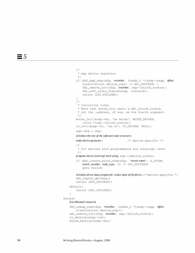
98 Writing Device Drivers—August, 1994
5
/* * map device registers */if (ddi_map_regs(dip, rnumber, (caddr_t *)&xsp->regp, offset,
sizeof(struct device_reg)) != DDI_SUCCESS) {ddi_remove_intr(dip, inumber, xsp->iblock_cookie);ddi_soft_state_free(statep, instance);return (DDI_FAILURE);
}/* * initialize locks * Note that mutex_init wants a ddi_iblock_cookie, * not the _address_ of one, as the fourth argument. */mutex_init(&xsp->mu, "xx mutex", MUTEX_DRIVER,
(void *)xsp->iblock_cookie);cv_init(&xsp->cv, "xx cv", CV_DRIVER, NULL);
xsp->dip = dip;
initialize the rest of the software state structure;
make device quiescent; /* device-specific */
/* * for devices with programmable bus interrupt level */program device interrupt level using xsp->idevice_cookie;
if (ddi_create_minor_node(dip, " minor name", S_IFCHR,minor_number, node_type, 0) != DDI_SUCCESS)goto failed;
initialize driver data, prepare for a later open of the device;/*device-specific */ddi_report_dev(dip);return (DDI_SUCCESS);
default:return (DDI_FAILURE);
}
failed:free allocated resources
ddi_unmap_regs(dip, rnumber, (caddr_t *)&xsp->regp, offset,sizeof(struct device_reg));
ddi_remove_intr(dip, inumber, xsp->iblock_cookie);cv_destroy(&xsp->cv);mutex_destroy(&xsp->mu);

Autoconfiguration 99
5
ddi_soft_state_free(statep, instance);return (DDI_FAILURE);
}
attach (9E) first checks for the DDI_ATTACH command, which is the only oneit handles. Future releases may support additional commands; consequently, itis important that drivers return DDI_FAILURE for all the commands they donot recognize. attach (9E) then calls ddi_get_instance (9F) to get theinstance number the system has assigned to the dev_info node indicated bydip .
Since the driver must be able to return a pointer to its dev_info node for eachinstance, attach (9E) must save dip , usually in a field of a per-instance statestructure. The example also requires DMA capability, so ddi_slaveonly (9F)is called to check if the slot is capable of DMA. The section “SBus Slots” onpage 18 discusses one example of such SBus hardware.
If any of the resource allocation routines fail, the code at the failed labelshould free any resources that had already been allocated before returningDDI_FAILURE . This can be done with a series of checks that look like this:
if (xsp->regp)ddi_unmap_regs(dip, rnumber, (caddr_t)&xsp->regp, offset,
sizeof(struct device_reg));
There should be such a check and a deallocation operation for each allocationoperation that may have been performed.
Registering Interrupts
In the call to ddi_add_intr (9F), inumber specifies which of several possibleinterrupt specifications is to be handled by intr_handler. For example, if thedevice interrupts at only one level, pass 0 for inumber .The interruptspecifications being referred to by inumber are described by the interruptsproperty (see driver.conf (4), isa (4), eisa (4), mca(4), sysbus (4), vme(4),and sbus (4)). intr_handler is a pointer to a function, in this case xxintr() , tobe called when the device issues the specified interrupt. intr_handler_arg is anargument of type caddr_t to be passed to intr_handler. intr_handler_arg maybe a pointer to a data structure representing the device instance that issued theinterrupt. ddi_add_intr (9F) returns an interrupt block cookie inxsp->iblock_cookie for use in calls to mutex_init (9F); it also returns a

100 Writing Device Drivers—August, 1994
5
device cookie in xsp->idevice_cookie for use with devices havingprogrammable bus-interrupt levels. The device cookie contains the followingfields:
u_short idev_vector;u_short idev_priority;
The idev_priority field of the returned structure contains the bus interruptpriority level, and the idev_vector field contains the vector number for vectoredbus architectures such as VMEbus.
Note – There is a potential race condition in attach (9E). The interrupt routineis eligible to be called as soon as ddi_add_intr (9F) returns. This may resultin the interrupt routine being called before any mutexes have been initializedwith the interrupt block cookie. If the interrupt routine acquires the mutexbefore it has been initialized, undefined behavior may result. See “RegisteringInterrupts” on page 111 for a solution to this problem.
Mapping Device Drivers
In the ddi_map_regs (9F) call, dip is the dev_info pointer passed toattach (9E). rnumber specifies which register set to map if there is more thanone. For devices with only one register set, pass 0 for rnumber.The registerspecifications referred to by rnumber are described by the reg property (seedriver.conf (4), isa (4), eisa (4), mca(4), sysbus (4), vme(4) and sbus (4)).ddi_map_regs (9F) maps a device register set (register specification) andreturns a kernel virtual address in xsp->regp . This address is offset bytes fromthe base of the device register set, and the mapping extends sizeof(structdevice_reg) bytes beyond that. To map all of a register set, pass zero foroffset and the length.
Minor Device Nodes
A minor device node contains the information exported by the device that thesystem uses to create a special file for the device under /devices in thefilesystem.
In the call to ddi_create_minor_node (9F), the minor name is the characterstring that is the last part of the base name of the special file to be created forthis minor device number; for example, "b,raw " in

Autoconfiguration 101
5
"fd@1,f7200000:b,raw ". S_IFCHR means create a character special file.Finally, the node type is one of the following system macros, or any stringconstant that does not conflict with the values of these macros (Seeddi_create_minor_node (9F) for more information).
The node types DDI_NT_BLOCK, DDI_NT_BLOCK_CHAN, DDI_NT_CD andDDI_NT_CD_CHAN causes disks (1M) to identify the device instance as a diskand to create a symbolic link in the /dev/dsk or /dev/rdsk directorypointing to the device node in the /devices directory tree.
The node type DDI_NT_TAPE causes tapes (1M) to identify the device instanceas a tape and to create a symbolic link from the /dev/rmt directory to thedevice node in the /devices directory tree.
The node type DDI_NT_SERIAL causes ports (1M) to identify the deviceinstance as a serial port and to create symbolic links from the /dev/term and/dev/cua directories to the device node in the /devices directory tree and toadd a new entry to /etc/inittab .
Table 5-1 Possible node types
Constant Description
DDI_NT_SERIAL Serial port
DDI_NT_SERIAL_DO Dialout ports
DDI_NT_BLOCK Hard disks
DDI_NT_BLOCK_CHAN Hard disks with channel or target numbers
DDI_NT_CD ROM drives (CDROM)
DDI_NT_CD_CHAN ROM drives with channel or target numbers
DDI_NT_FD Floppy disks
DDI_NT_TAPE Tape drives
DDI_NT_NET Network devices
DDI_NT_DISPLAY Display devices
DDI_PSEUDO General pseudo devices

102 Writing Device Drivers—August, 1994
5
Vendor supplied strings should include an identifying value to make themunique, such as their name or stock symbol (if appropriate). The string (alongwith the other node types not consumed by disks (1M), tapes (1M), orports (1M) can be used in conjunction with devlinks (1M) anddevlink.tab (4) to create logical names in /dev .
Deferred Attach
open (9E) might be called before attach (9E) has succeeded. open (9E) mustthen return ENXIO, which will cause the system to attempt to attach the device.If the attach succeeds, the open is retried automatically.
detach( )
detach (9E) is the inverse operation to attach (9E). It is called for each deviceinstance, receiving a command of DDI_DETACH, when the system attempts tounload a driver module. The system only calls the DDI_DETACH case ofdetach (9E) for a device instance if the device instance is not open. No calls toother driver entry points for that device instance occurs during detach (9E),although interrupts and time-outs may occur.
The main purpose of detach (9E) is to free resources allocated by attach (9E)for the specified device. For example, detach (9E) should unmap any mappeddevice registers, remove any interrupts registered with the system, and free thesoft state structure for this device instance.
If the detach (9E) routine entry in the dev_ops (9S) structure is initialized tonodev , it implies that detach (9E) always fails, and the driver will not beunloaded. This is the simplest way to specify that a driver is not unloadable.
Code Example 5-5 detach (9E) routine
static intxxdetach(dev_info_t *dip, ddi_detach_cmd_t cmd){
struct xxstate *xsp;int instance;
switch (cmd) {case DDI_DETACH:
instance = ddi_get_instance(dip);xsp = ddi_get_soft_state(statep, instance);

Autoconfiguration 103
5
make device quiescent; /* device-specific */
ddi_remove_minor_node(dip, NULL);
ddi_unmap_regs(dip, rnumber, (caddr_t)&xsp->regp,offset, sizeof(struct device_reg));
ddi_remove_intr(dip, inumber, xsp->iblock_cookie);
mutex_destroy(&xsp->mu);cv_destroy(&xsp->cv);ddi_soft_state_free(statep, instance);return (DDI_SUCCESS);
default:return (DDI_FAILURE);
}}
In the call to ddi_unmap_regs (9F), rnumber and offset are the same valuespassed to ddi_map_regs (9F) in attach (9E). Similarly, in the call toddi_remove_intr (9F), inumber is the same value that was passed toddi_add_intr (9F).
Callbacks
The detach (9E) routine must not return DDI_SUCCESS while it has callbackfunctions pending. This is only critical for callbacks registered for deviceinstances that are not currently open, since the DDI_DETACH case is notentered if the device is open.
There are two types of callback routines of interest: callbacks that can becancelled, and callbacks that must run to completion.
Callbacks that can be cancelled do not pose a problem; just remember to cancelthe callback before detach (9E) returns DDI_SUCCESS. Each of the callbackcancellation routines in Table 5-2 atomically cancels callbacks so that a callbackroutine does not run while it is being cancelled.
Table 5-2 Example of functions with callbacks that can be cancelled.
Function Cancelling function
timeout (9F) untimeout (9F)
bufcall (9F) unbufcall (9F)
esbbcall (9F) unbufcall (9F)
104 Writing Device Drivers—August, 1994
5
Some callbacks cannot be cancelled—for these it is necessary to wait until thecallback has been called. In some cases, such as ddi_dma_setup (9F), thecallback must also be prevented from rescheduling itself. See “Cancelling DMACallbacks” on page 140 for an example.
Following is a list of some functions that may establish callbacks that cannot becancelled:
• esballoc (9F)• ddi_dma_setup (9F)• ddi_dma_addr_setup (9F)• ddi_dma_buf_setup (9F)• scsi_dmaget (9F)• scsi_resalloc (9F)• scsi_pktalloc (9F)• scsi_init_pkt (9F)
getinfo( )
The system calls getinfo(9E) to obtain configuration information that onlythe driver knows. The mapping of minor numbers to device instances isentirely under the control of the driver. The system sometimes needs to ask thedriver which device a particular dev_t represents.
getinfo (9E) is called during module loading and at other times during thelife of the driver. It can take one of two commands as its infocmd argument:DDI_INFO_DEVT2INSTANCE, which asks for a device’s instance number, andDDI_INFO_DEVT2DEVINFO, which asks for pointer to the device’s dev_infostructure.
In the DDI_INFO_DEVT2INSTANCE case, arg is a dev_t , and getinfo (9E)must translate the minor number to an instance number. In the followingexample, the minor number is the instance number, so it simply passes backthe minor number. In this case, the driver must not assume that a statestructure is available, since getinfo (9E) may be called before attach (9E).The mapping the driver defines between minor device number and instancenumber does not necessarily follow the mapping shown in the example. In allcases, however, the mapping must be static.

Autoconfiguration 105
5
In the DDI_INFO_DEVT2DEVINFO case, arg is again a dev_t , so getinfo (9E)first decodes the instance number for the device. It then passes back thedev_info pointer saved in the driver’s soft state structure for the appropriatedevice.
Code Example 5-1 getinfo (9E) routine
static intxxgetinfo(dev_info_t *dip, ddi_info_cmd_t infocmd, void *arg, void **result){
struct xxstate *xsp;dev_t dev;int instance, error;
switch (infocmd) {case DDI_INFO_DEVT2INSTANCE:
dev = (dev_t) arg;*result = (void *) getminor(dev);error = DDI_SUCCESS;break;
case DDI_INFO_DEVT2DEVINFO:dev = (dev_t) arg;instance = getminor(dev);xsp = ddi_get_soft_state(statep, instance);if (xsp == NULL)
return (DDI_FAILURE);*result = (void *) xsp->dip;error = DDI_SUCCESS;break;
default:error = DDI_FAILURE;break;
}return (error);
}

106 Writing Device Drivers—August, 1994
5
107
Interrupt Handlers 6
This chapter describes the interrupt handling mechanisms of the Solaris 2.xDDI/DKI. This includes registering, servicing, and removing interrupts.
OverviewAn interrupt is a hardware signal from a device to the CPU. It tells the CPUthat the device needs attention, and the CPU should drop whatever it is doingand respond to the device. If the CPU is available (it is not doing somethingthat is higher priority, such as servicing a higher priority interrupt) it suspendsthe current thread and eventually invokes the interrupt handler for that device.The job of the interrupt handler is to service the device, and stop it frominterrupting. Once the handler returns, the CPU resumes whatever it wasdoing before the interrupt occurred.
The Solaris 2.x DDI/DKI provides a bus-architecture independent interface forregistering and servicing interrupts. Drivers must register their deviceinterrupts before they can receive and service interrupts.
Example
On x86 platforms, a device requests an interrupt by asserting an interruptrequest line (IRQ) on the system bus. The bus implements multiple IRQ lines,and a particular device may be able to generate interrupts on one or more ofthem. Multiple devices may share a common IRQ line.
108 Writing Device Drivers—August, 1994
6
The bus IRQ lines are connected to an interrupt controller that arbitratesbetween interrupt requests. The kernel programs the interrupt controller toselect which interrupts should be enabled at any particular time. When theinterrupt controller determines that an interrupt should be delivered, it raises arequest to the CPU. If processor interrupts are enabled, the CPU acknowledgesthe interrupt and causes the kernel to begin interrupt handler processing.
Interrupt Specification
An interrupt specification is the information the system needs in order to link aninterrupt handler with a given interrupt. It describes the information providedby the hardware to the system when making an interrupt request. Interruptspecifications typically includes a bus-interrupt level. For vectored interrupts itincludes an interrupt vector. On x86 platforms the driver.conf (4) file specifiesthe relative priority of the devices interrupt. See isa(4) , eisa(4), mca(4),sbus (4), and vme(4) for specific information on interrupt specifications forthese buses.
Interrupt Number
When registering interrupts the driver must provide the system with aninterrupt number. This identifies which interrupt specification the driver isregistering a handler for. Most devices have one interrupt, interrupt numberzero. However, there are devices that have different interrupts for differentevents. A communications controller may have one interrupt for receive readyand one for transmit ready. The device driver normally knows how manyinterrupts the device has, but if the driver has to support several variations ofa controller it can call ddi_dev_nintrs (9F) to find out the number of deviceinterrupts. For a device with n interrupts, the interrupt numbers range from 0to n-1.
Bus-Interrupt Levels
Buses prioritize device interrupts at one of several bus-interrupt levels. Thesebus interrupt levels are then associated with different processor-interruptlevels. For example, SBus devices that interrupt at SBus level 7 interrupt atSPARC level 9 on SPARCstation 2 systems, but interrupt at SPARC level 13 onSPARCstation 10 systems.

Interrupt Handlers 109
6
High-Level Interrupts
A bus-interrupt level that maps to a CPU interrupt priority level above thescheduler priority level is called a high-level interrupt. High-level interruptsmust be handled without using system services that manipulate threads. Inparticular, the only kernel routines that high-level interrupt handlers areallowed to call are:
• mutex_enter (9F) and mutex_exit (9F) on a mutex initialized with aninterrupt block cookie associated with the high-level interrupt.
• ddi_trigger_softintr (9F).
A bus-interrupt level by itself does not determine whether a device interruptsat high-level: a given bus-interrupt level may map to a high-level interrupt onone platform, but map to an ordinary interrupt on another platform. Thefunction ddi_intr_hilevel (9F), given an interrupt number, returns a valueindicating whether the interrupt is high-level.
The driver can choose whether or not to support high-level interrupts, but italways has to check —it cannot assume that its interrupts are not high-level. Forinformation on checking for high-level interrupts see “Registering Interrupts”on page 111.
Types of InterruptsThere are two common ways to request for an interrupt: vectored and polled.Both methods commonly specify a bus-interrupt priority level. Their onlydifference is that vectored devices also specify an interrupt vector, but polleddevices do not.
Vectored Interrupts
Devices that use vectored interrupts are assigned an interrupt vector. This is anumber that identifies that particular interrupt handler. This vector may befixed, configurable (using jumpers or switches), or programmable. In the caseof programmable devices, an interrupt device cookie is used to program thedevice interrupt vector. When the interrupt handler is registered, the kernelsaves the vector in a table.

110 Writing Device Drivers—August, 1994
6
When the device interrupts, the system enters the interrupt acknowledge cycle,asking the interrupting device to identify itself. The device responds with itsinterrupt vector. The kernel then uses this vector to find the responsibleinterrupt handler.
The VMEbus supports vectored interrupts.
Polled Interrupts
In polled (or autovectored) devices, the only information the system has about adevice interrupt is its bus-interrupt priority level. When a handler is registered,the system adds the handler to list of potential interrupt handlers for the bus-interrupt level. When an interrupt occurs, the system must determine whichdevice, of all the devices at that level, actually interrupted. It does this bycalling all the interrupt handlers for that bus-interrupt level until one of themclaims the interrupt.
The SBus supports polled interrupts.
Software Interrupts
The Solaris 2.x DDI/DKI supports software interrupts, also known as softinterrupts. Soft interrupts are not initiated by a hardware device, they areinitiated by software. Handlers for these interrupts must also be added to andremoved from the system. Soft interrupt handlers run in interrupt context andtherefore can be used to do many of the tasks that belong to an interrupthandler.
Commonly, hardware interrupt handlers are supposed to be very quick, sincethey may suspend other system activity while running (particularly in high-level interrupt handlers). For example, they may prevent lower-priorityinterrupts from occurring while they run. For this reason, hardware interrupthandlers should do the minimum amount of work needed to service thedevice.
Software interrupt handlers run at a lower priority than hardware interrupthandlers, so they can do more work without seriously impacting theperformance of the system. Additionally, if the hardware interrupt handler ishigh-level, it is severely restricted in what it can do. In this case, it is a goodidea to simply trigger a software interrupt in the high-level handler and put allpossible processing in the lower-level software interrupt handler.

Interrupt Handlers 111
6
Software interrupt handlers must not assume that they have work to do whenthey run, since (like hardware interrupt handlers) they can run because someother driver triggered a soft interrupt. For this reason, the driver must indicateto the soft interrupt handler that it should do work before triggering the softinterrupt.
Registering InterruptsBefore a device can receive and service interrupts, it must register them withthe system by calling ddi_add_intr (9F). This provides the system with a wayto associate an interrupt handler with an interrupt specification. This interrupthandler is called when the device might have been responsible for theinterrupt. It is the handlers responsibility to determine if it should handle theinterrupt, and claim it if so.
The following steps are usually performed in attach (9E):
• Test for high-level interrupts.Call ddi_intr_hilevel (9F) to find out if the interrupt specification mapsto a high-level interrupt. If it does, one possibility is to post a message tothat effect and return DDI_FAILURE . Code Example 6-1 on page 110 doesthis.
• Add the interrupt.
• Initialize any associated mutexes.There is a potential race condition between adding the interrupt handlerand initializing mutexes. The interrupt routine is eligible to be called assoon as ddi_add_intr (9F) returns, as another device might interrupt andcause the handler to be invoked. This may result in the interrupt routinebeing called before any mutexes have been initialized with the returnedinterrupt block cookie. If the interrupt routine acquires the mutex before ithas been initialized, undefined behavior may result.
The solution to this problem is to use ddi_add_intr (9F) to add aninterrupt handler that never claims the interrupt. This allows the driver toget the interrupt block cookie for the interrupt, which it can then use toinitialize any mutexes. Once the mutexes are initialized, the temporaryinterrupt handler can be removed, and the real one installed. nulldev (9F)can be used as the temporary handler, though it needs to be cast properly.See Code Example 6-1 for an example.

112 Writing Device Drivers—August, 1994
6
Code Example 6-1 attach (9E) routine with temporary interrupt handler
static intxxattach(dev_info_t *dip, ddi_attach_cmd_t cmd){
struct xxstate *xsp;
if (cmd != DDI_ATTACH)return (DDI_FAILURE);
...
if (ddi_intr_hilevel(dip, inumber) != 0){cmn_err(CE_CONT,
“xx: high-level interrupts are not supported\n”);return (DDI_FAILURE);
}
/* * The interrupt routine will grab the mutex, so a null */ * handler is required. */if (ddi_add_intr(dip, inumber, &xsp->iblock_cookie,
NULL, (u_int (*)(caddr_t))nulldev, NULL) != DDI_SUCCESS){cmn_err(CE_WARN, "xx: cannot add interrupt handler.");return (DDI_FAILURE);
}
mutex_init(&xsp->mu, "xx mutex", MUTEX_DRIVER,(void *) xsp->iblock_cookie);
ddi_remove_intr(dip, inumber, xsp->iblock_cookie);
if (ddi_add_intr(dip, inumber, &xsp->iblock_cookie,&xsp->idevice_cookie, xxintr, (caddr_t)xsp) != DDI_SUCCESS){cmn_err(CE_WARN, "xx: cannot add interrupt handler.");goto failed;
}cv_init(&xsp->cv, "xx cv", CV_DRIVER, NULL);return (DDI_SUCCESS);
failed:remove interrupt handler if necessary, destroy mutexreturn (DDI_FAILURE);
}

Interrupt Handlers 113
6
Responsibilities of an Interrupt HandlerThe interrupt handler has a set of responsibilities to perform. Some arerequired by the framework, and some are required by the device. All interrupthandlers are required to do the following:
1. Possibly reject the interrupt.The interrupt handler must first examine the device and determine if it hasissued the interrupt. If it has not, the handler must returnDDI_INTR_UNCLAIMED. This step allows the implementation of devicepolling: it tells the system whether this device, among a number of devices atthe given interrupt priority level, has issued the interrupt.
2. Inform the device that it is being serviced.This is a device-specific operation, but is required for the majority ofdevices. For example, SBus devices are required to interrupt until the drivertells them to stop. This guarantees that all SBus devices interrupting at thesame priority level will be serviced.
Most vectored devices, on the other hand, stop interrupting after the businterrupt acknowledge cycle; however, their internal state still indicates thatthey have interrupted but have not been serviced yet.
3. Perform any I/O request related processing.Devices interrupt for different reasons, such as transfer done or transfer error.This step may involve reading the device’s data buffer, examining thedevice’s error register, and setting the status field in a data structureaccordingly.
Interrupt dispatching and processing is relatively expensive. The followingpoints apply to interrupt processing:
• Do only what absolutely requires interrupt context.• Do any additional processing that could save another interrupt, for
example, read the next data from the device.
4. Return DDI_INTR_CLAIMED.
Code Example 6-2 Interrupt routine
static u_intxxintr(caddr_t arg){

114 Writing Device Drivers—August, 1994
6
struct xxstate *xsp = (struct xxstate *) arg;u_char status, temp;
/* * Claim or reject the interrupt.This example assumes * that the device’s CSR includes this information. */mutex_enter(&xsp->mu);status = xsp->regp->csr;
if (!(status & INTERRUPTING)) {mutex_exit(&xsp->mu);return (DDI_INTR_UNCLAIMED);
}
/* * Inform the device that it is being serviced, and re-enable * interrupts. The example assumes that writing to the * CSR accomplishes this. The driver must ensure that this write * operation makes it to the device before the interrupt service * returns. For example, reading the CSR, if it does not result in * unwanted effects, can ensure this. */xsp->regp->csr = CLEAR_INTERRUPT | ENABLE_INTERRUPTS;temp = xsp->regp->csr;
perform any I/O related and synchronization processing
signal waiting threads (biodone(9F) or cv_signal(9F))
mutex_exit(&xsp->mu);return (DDI_INTR_CLAIMED);
}
On an architecture that does not support vectored hardware interrupts, whenthe system detects an interrupt, it calls the driver interrupt handler function foreach device that could have issued the interrupt. The interrupt handler mustdetermine whether the device it handles issued an interrupt. On architecturessupporting vectored interrupts, this step is unnecessary but not harmful, and itenhances portability. The syntax and semantics of the interrupt handlingroutine therefore can be the same for both vectored interrupts and pollinginterrupts.
In the model presented here, the argument passed to xxintr() is a pointer tothe state structure for the device that may have issued the interrupt. This wasbe set up by passing a pointer to the state structure as the intr_handler_argargument to ddi_add_intr (9F) in attach (9E)

Interrupt Handlers 115
6
Most of the steps performed by the interrupt routine depend on the specifics ofthe device itself. Consult the hardware manual for the device to learn how todetermine the cause of the interrupt, detect error conditions, and access thedevice data registers.
State StructureThis section adds the following fields to the state structure. See “StateStructure” on page 57 for more information.
ddi_iblock_cookie_t high_iblock_cookie;ddi_idevice_cookie_t high_idevice_cookie;kmutex_t high_mu;int softint_running;ddi_iblock_cookie_t low_iblock_cookie;kmutex_t low_mu;ddi_softintr_t id;
Handling High-Level InterruptsHigh-level interrupts are those that interrupt at the level of the scheduler andabove. This level does not allow the scheduler to run, therefore high-levelinterrupt handlers cannot be preempted by the scheduler, nor can they rely onthe scheduler (cannot block)—they can only use mutual exclusion locks forlocking.
Because of this, the driver must use ddi_intr_hilevel (9F) to determine if ituses high-level interrupts. If ddi_intr_hilevel (9F) returns true, the drivercan fail to attach, or it can use a two-level scheme to handle them. Properlyhandling high-level interrupts is the preferred solution.
Note – By writing the driver as if it always uses high level interrupts, aseparate case can be avoided. However, this does result in an extra (software)interrupt for each hardware interrupt.
The suggested method is to add a high-level interrupt handler, which justtriggers a lower-priority software interrupt to handle the device. The drivershould allow more concurrency by using a separate mutex for protecting datafrom the high-level handler.
116 Writing Device Drivers—August, 1994
6
High-level Mutexes
A mutex initialized with the interrupt block cookie that represents a high-levelinterrupt is known as a high-level mutex. While holding a high-level mutex, thedriver is subject to the same restrictions as a high-level interrupt handler. Theonly routines it can call are:
• mutex_exit (9F) to release the high-level mutex.
• ddi_trigger_softintr (9F) to trigger a soft interrupt.
Example
In the model presented here, the high-level mutex (xsp->high_mu ) is onlyused to protect data shared between the high-level interrupt handler and thesoft interrupt handler. This includes a queue that the high-level interrupthandler appends data to (and the low-level handler removes data from), and aflag that indicates the low-level handler is running. A separate low-level mutex(xsp->low_mu ) is used to protect the rest of the driver from the soft interrupthandler.
Code Example 6-3 attach (9E) routine handling high-level interrupts
static intxxattach(dev_info_t *dip, ddi_attach_cmd_t cmd){
struct xxstate *xsp;
...
if (ddi_intr_hilevel(dip, inumber)) {/* add null high-level handler */if (ddi_add_intr(dip, inumber, &xsp->high_iblock_cookie,
NULL, (u_int (*)(caddr_t))nulldev, NULL) != DDI_SUCCESS)goto failed;
mutex_init(&xsp->high_mu, "xx high mutex", MUTEX_DRIVER,(void *)xsp->high_iblock_cookie);
ddi_remove_intr(dip, inumber, xsp->high_iblock_cookie);
if (ddi_add_intr(dip, inumber, &xsp->high_iblock_cookie,&xsp->high_idevice_cookie, xxhighintr, (caddr_t) xsp)!= DDI_SUCCESS)goto failed;

Interrupt Handlers 117
6
/* add null low-level handler */if (ddi_add_softintr(dip, DDI_SOFTINT_HI, &xsp->id,
&xsp->low_iblock_cookie, NULL,(u_int (*)(caddr_t))nulldev, NULL))!= DDI_SUCCESS)goto failed;
mutex_init(&xsp->low_mu, "xx low mutex", MUTEX_DRIVER,(void *) xsp->low_iblock_cookie);
ddi_remove_softintr(xsp->id);
if (ddi_add_softintr(dip, DDI_SOFTINT_HI, &xsp->id,&xsp->low_iblock_cookie, NULL,xxlowintr, (caddr_t)xsp)) != DDI_SUCCESS)goto failed;
} else {add normal interrupt handler
}
cv_init(&xsp->cv, "xx condvar", CV_DRIVER, NULL);...
return (DDI_SUCCESS);
failed:free allocated resources, remove interrupt handlers
return (DDI_FAILURE);}
The high-level interrupt routine services the device, and enqueues the data.The high-level routine triggers a software interrupt if the low-level routine isnot running.
Code Example 6-4 High-level interrupt routine
static u_intxxhighintr(caddr_t arg){
struct xxstate *xsp = (struct xxstate *)arg;u_char status, temp;int need_softint;
mutex_enter(&xsp->high_mu);/* read status */status = xsp->regp->csr;

118 Writing Device Drivers—August, 1994
6
if (!(status & INTERRUPTING)) {mutex_exit(&xsp->high_mu);return (DDI_INTR_UNCLAIMED); /* device isn’t interrupting */
}xsp->regp->csr = CLEAR_INTERRUPT;/* Flush store buffers */temp = xsp->regp->csr;
read data from device and queue the data for the low-level interrupt handler;
if (xsp->softint_running)need_softint = 0;
elseneed_softint = 1;
mutex_exit(&xsp->high_mutex);
/* read-only access to xsp->id, no mutex needed */if (need_softint)
ddi_trigger_softintr(xsp->id);
return (DDI_INTR_CLAIMED);}
The low-level interrupt routine is started by the high-level interrupt routinetriggering a software interrupt. Once running, it should continue to do so untilthere is nothing left to process.
Code Example 6-5 Low-level interrupt routine
static u_intxxlowintr(caddr_t arg){
struct xxstate *xsp = (struct xxstate *) arg;
....mutex_enter(&xsp->low_mu);mutex_enter(&xsp->high_mu);if ( queue empty || xsp->softint_running ) {
mutex_exit(&xsp->high_mu);mutex_exit(&xsp->low_mu);return (DDI_INTR_UNCLAIMED);
}
xsp->softint_running = 1;
while ( data on queue ) {ASSERT(mutex_owned(&xsp->high_mu);
dequeue data from high level queue;mutex_exit(&xsp->high_mu);

Interrupt Handlers 119
6
normal interrupt processing
mutex_enter(&xsp->high_mu);}
xsp->softint_running = 0;
mutex_exit(&xsp->high_mu);mutex_exit(&xsp->low_mu);
return (DDI_INTR_CLAIMED);}

120 Writing Device Drivers—August, 1994
6

121
DMA 7
Many devices can temporarily take control of the bus and perform datatransfers to (and from) main memory or other devices. Since the device isdoing the work without the help of the CPU, this type of data transfer isknown as a direct memory access (DMA). DMA transfers can be performedbetween two devices, between a device and memory, or between memory andmemory. This chapter describes transfers between a device and memory only.
The DMA ModelThe Solaris 2.x DDI/DKI provides a high-level, architecture-independentmodel for DMA. This allows the framework (the DMA routines) to hidearchitecture-specific details such as:
• Setting up DMA mappings• Building scatter-gather lists.• Ensuring I/O and CPU caches are consistent.
There are several abstractions that are used in the DDI/DKI to describe aspectsof a DMA transaction. These include:
• DMA Object
Memory that is the source or destination of a DMA transfer.
• DMA Handle

122 Writing Device Drivers—August, 1994
7
An opaque object returned from a successful DMA setup call. The DMAhandle can be used in successive DMA subroutine calls to refer to the DMAobject.
• DMA Window
A DMA window describes all or a portion of a DMA object that is ready toaccept data transfers.
• DMA Segment
A DMA segment is a contiguous portion of a DMA window that is entirelyaddressable by the device.
• DMA Cookie
A ddi_dma_cookie (9S) structure (ddi_dma_cookie_t ) describes a DMAsegment. It contains DMA addressing information required to program theDMA engine.
Rather than knowing that a platform needs to map an object (typically amemory buffer) into a special DMA area of the kernel address space, devicedrivers instead allocate DMA resources for the object. The DMA routines thenperform any platform-specific operations needed to set the object up for DMAaccess. The driver receives a DMA handle to identify the DMA resourcesallocated for the object. This handle is opaque to the device driver; the drivermust save the handle and pass it in subsequent calls to DMA routines, butshould not interpret it in any way.
Operations are defined on a DMA handle that provide the following services:
• Manipulating DMA resources• Synchronizing DMA objects• Retrieving attributes of the allocated resources
Figure 7-1 shows the relationship between the DMA object, the DMA handle,and the DMA windows, segments, and cookies.
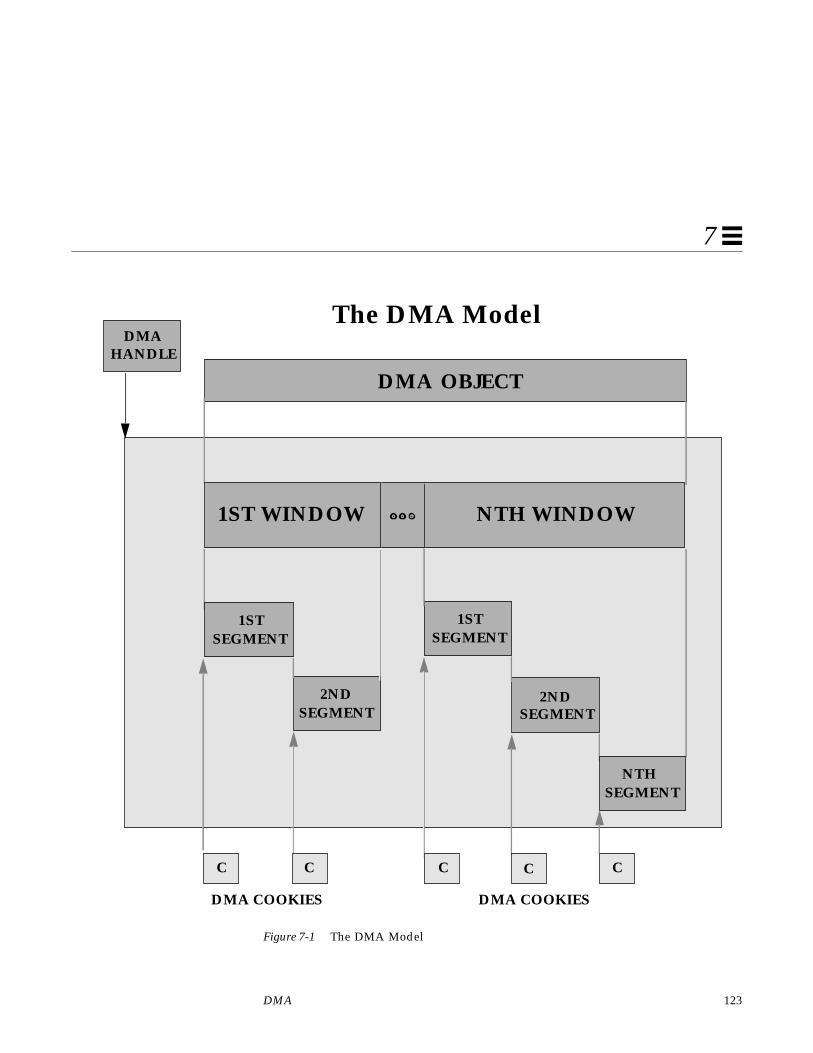
DMA 123
7
Figure 7-1 The DMA Model
1STSEGMENT
DMAHANDLE
DMA OBJECT
The DMA Model
2NDSEGMENT
2NDSEGMENT
NTHSEGMENT
1STSEGMENT
DMA COOKIES DMA COOKIES
1ST WINDOW NTH WINDOW
C C C C C

124 Writing Device Drivers—August, 1994
7
Types of Device DMADevices may perform one of the following three types of DMA:
Bus Master DMAIf the device is capable of acting as a true bus master, then the driver shouldprogram the device’s DMA registers directly. The transfer address and count isobtained from the cookie and given to the device.
Devices on current SPARC platforms use this form of DMA exclusively.
Third-party DMAThird-party DMA utilizes a system DMA engine resident on the main systemboard, which has several DMA channels available for use by devices. Thedevice relies on the system’s DMA engine to perform the data transfersbetween the device and memory. The driver uses DMA engine routines (seeddi_dmae (9F)) to initialize and program the DMA engine. For each DMA datatransfer, the driver programs the DMA engine and then gives the device acommand to initiate the transfer in cooperation with that engine.
First-party DMAUnder first-party DMA, the device drives its own DMA bus cycles using achannel from the system’s DMA engine. The ddi_dmae_1stparty (9F)function is used to configure this channel in a cascade mode such that theDMA engine will not interfere with the transfer.
DMA and DVMAThe platform that the device operates on may provide one of two types ofmemory access: Direct Memory Access (DMA) or Direct Virtual MemoryAccess (DVMA).
On platforms that support DMA, the device is provided with a physicaladdress by the system in order to perform transfers. In this case, one logicaltransfer may actually consist of a number of physically discontiguous transfers.An example of this occurs when an application transfers a buffer that spansseveral contiguous virtual pages that map to physically discontiguous pages.In order to deal with the discontiguous memory, devices for these platforms

DMA 125
7
usually have some kind of scatter/gather DMA capability. Typically the systemthat supports x86 platforms provides physical addresses for direct memorytransfers.
On platforms that support DVMA, the device is provided with a virtualaddress by the system in order to perform transfers. In this case, theunderlying platform provides some form of MMU which translates deviceaccesses to these virtual addresses into the proper physical addresses. Thedevice transfers to and from a contiguous virtual image that may be mapped todiscontiguous virtual pages. Devices that operate in these platforms don’t needscatter/gather DMA capability. Typically the system which supports SPARCplatforms provides virtual addresses for direct memory transfers.
Handles, Windows, Segments and CookiesA DMA handle is an opaque pointer representing an object (usually a memorybuffer or address) where a device can perform DMA transfer. The handle isused in several different calls to DMA routines to identify the DMA resourcesallocated for the object.
An object represented by a DMA handle is completely covered by one or moreDMA windows. The system uses the information in the DMA limit structure,and the memory location and alignment of the target object, to decide how todivide an object into multiple windows in order to fit the request withinsystem resource limitations. The ddi_dma_nextwin (9F) function takes a DMAhandle obtained from a DMA setup function and a previous window (or NULLfor the first window) and passes back the next (or first) window of the object.An active DMA window may represent allocated resources, such asintermediate buffers. The resources will be released upon the next call toddi_dma_nextwin (9F) or when the DMA resources are freed usingddi_dma_free (9F).
A DMA window can span several discontiguous pages of system memory. Ifthe DMA engine does not have a memory map, a DMA window might have tobe broken into multiple DMA segments, each representing a contiguous piece ofmemory to or from which the DMA engine can transfer data. Theddi_dma_nextseg (9F) function takes a DMA window obtained fromddi_dma_nextwin (9F) and a previous segment (or NULL for the firstsegment) and returns the next (or first) segment in the window. A segmentrepresents a contiguous object that is completely addressable in one DMAcookie.

126 Writing Device Drivers—August, 1994
7
The DMA cookie is a data structure that contains information (such as thetransfer address and count) needed to program the DMA engine (seeddi_dma_cookie (9S)). The ddi_dma_segtocookie (9F) function takes aDMA segment obtained from ddi_dma_nextseg (9F) and passes back a DMAcookie for that segment.
Scatter/Gather
Some DMA engines may be able to accept more than one cookie. Such enginescan perform scatter/gather I/O without the help of the system. In this case, itis most efficient if the driver uses ddi_dma_nextseg (9F) andddi_dma_segtocookie( 9F) to get as many cookies as the DMA engine canhandle and program them all into the engine. The device can then beprogrammed to transfer the total number of bytes covered by all thesesegments combined.
DMA OperationsThe steps involved in a DMA transfer are similar among the types of DMA.
Bus-master DMAIn general, here are the steps that must be followed to perform bus-masterDMA.
1. Describe the device limitations. This allows the routines to ensure that thedevice will be able to access the buffer.
2. Lock the DMA objects in memory (see physio (9F).
Note – This step is not necessary in block drivers for buffers coming from thefile system, as the file system has already locked the data in memory.
3. Allocate DMA resources for the object.
4. Retrieve the next DMA window with ddi_dma_nextwin (9F).
5. Retrieve the next segment in the window with ddi_dma_nextseg (9F).
6. Get a DMA cookie for the segment with ddi_dma_segtocookie (9F).

DMA 127
7
7. Program the DMA engine on the device and start it (this is device-specific).
When the transfer is complete, continue the bus master operation:
8. Perform any required object synchronizations.
9. Transfer the rest of the window by repeating from Step 5.
10. Transfer the rest of the object by repeating from Step 4.
11. Release the DMA resources.
First-party DMAIn general, here are the steps that must be performed to perform first-partyDMA.
1. Allocate a DMA channel.
2. Configure the channel with ddi_dmae_1stparty (9F).
3. Lock the DMA objects in memory. This step is not necessary in block driversfor buffers coming from the file system, as the file system has already lockedthe data in memory.
4. Allocate DMA resources for the object.
5. Retrieve the next DMA window with ddi_dma_nextwin (9F).
6. Retrieve the next segment in the window with ddi_dma_nextseg (9F).
7. Get a DMA cookie for the segment with ddi_dma_segtocookie (9F).
Program the DMA engine and start it. When the transfer is complete, continuethe DMA operation:
8. Perform any required object synchronizations.
9. Transfer the rest of the window by repeating from Step 6.
10. Transfer the rest of the object by repeating from Step 5.
11. Release the DMA resources.
12. Deallocate the DMA channel.

128 Writing Device Drivers—August, 1994
7
Third-party DMAIn general, here are the steps that must be performed to perform third-partyDMA.
1. Allocate a DMA channel.
2. Retrieve the system’s DMA engine limitations with ddi_dmae_getlim (9F).
3. Lock the DMA objects in memory. This step is not necessary in block driversfor buffers coming from the file system, as the file system has already lockedthe data in memory.
4. Allocate DMA resources for the object.
5. Retrieve the next DMA window with ddi_dma_nextwin (9F).
6. Retrieve the next segment in the window with ddi_dma_nextseg (9F).
7. Get a DMA cookie for the segment with ddi_dma_segtocookie (9F).
8. Program the system DMA engine to perform the transfer withddi_dmae_prog (9F).
9. Perform any required object synchronizations.
10. Transfer the rest of the window by repeating from Step 6.
11. Transfer the rest of the object by repeating from Step 5.
12. Stop the DMA engine with ddi_dmae_stop (9F).
13. Release the DMA resources.
14. Deallocate the DMA channel.
Certain hardware platforms may restrict DMA capabilities in a bus-specificway. Drivers should use ddi_slaveonly (9F) to determine if the device is in aslot in which DMA is possible. For an example, see the attach() section onpage 95.
Device limitations
Device limitations describe the built-in restrictions of a DMA engine. Theselimits include:

DMA 129
7
• Limits on addresses the device can access• Maximum transfer count• Address alignment restrictions
To ensure that DMA resources allocated by the system can be accessed by thedevice’s DMA engine, device drivers must inform the system of their DMAengine limitations using a ddi_dma_lim (9S) structure. The system mayimpose additional restrictions on the device attributes, but it never removesany of the driver-supplied restrictions.
DMA Limits
All DMA resource-allocation routines take a pointer to a DMA limit structureas an argument (see Code Example 7-1 on page 134). This structure is currentlyprocessor-architecture dependant.
ddi_dma_lim_sparc
The SPARC DMA limit structure contains the following members:
typedef struct ddi_dma_lim_t {u_long dlim_addr_lo; /* lower bound of address range */u_long dlim_addr_hi; /* inclusive upper bound of address range */u_int dlim_minxfer; /* minimum effective DMA transfer size */u_int dlim_cntr_max; /* inclusive upper bound of address register */u_int dlim_burstsizes;/* bitmask encoded DMA burst sizes */u_int dlim_dmaspeed; /* average DMA data rate (KB/s) */
} ddi_dma_lim_t;
dlim_addr_lo is the lowest address that the DMA engine can access.
dlim_addr_hi is the highest address that the DMA engine can access.
dlim_minxfer is the minimum effective transfer size the device can perform.It also influences alignment and padding restrictions.
dlim_cntr_max is the upper bound of the DMA engine’s address register.This is often used where the upper 8 bits of an address register are a latchcontaining a segment number, and the lower 24 bits are used to address asegment. In this case, dlim_cntr_max would be set to 0x00FFFFFF ; thisprevents the system from crossing a 24-bit segment boundary whenestablishing mappings to the object.

130 Writing Device Drivers—August, 1994
7
dlim_burstsizes specifies the burst sizes that the device supports. A burstsize is the amount of data the device can transfer before relinquishing the bus.This member is a bitmask encoding of the burst sizes. For example, if thedevice is capable of doing 1, 2, 4, and 16 byte bursts, this field should be set to0x17. The system also uses this field to determine alignment restrictions. If thedevice is an SBus device and can take advantage of a 64-bit SBus, the lower 16bits are used to specify the burst size for 32-bit transfers, and the upper 16 bitsare used to specify the burst size for 64-bit transfers.
dlim_dmaspeed is the average speed of the DMA engine in KBytes/second.This is intended to be a hint for the resource allocation routines, but is optionaland may be zero.
ddi_dma_lim_x86The x86 DMA limit structure contains the following members:
typedef struct ddi_dma_lim {u_long dlim_addr_lo; /* lower bound of address range */u_long dlim_addr_hi; /* inclusive upper bound of address range */u_int dlim_cntr_max; /* set to 0 */u_int dlim_burstsizes;/* set to 1 */u_int dlim_minxfer; /* minimum DMA transfer size */u_int dlim_dmaspeed; /* set to 0 */u_int dlim_version; /* version number of this structure */u_int dlim_adreg_max;/* inclusive upper bound of incrementing address */
/* register */u_int dlim_ctreg_max;/* maximum transfer count - 1 */u_int dlim_granular; /* granularity of transfer count */u_int dlim_sgllen; /* length of DMA scatter/gather list */u_int dlim_reqsize; /* maximum transfer size (bytes) of a single I/O */
} ddi_dma_lim_t;
dlim_addr_lo is the lowest address that the DMA engine can access.
dlim_addr_hi is the highest address that the DMA engine can access.
dlim_minxfer is the minimum transfer size the DMA engine can perform. Italso influences alignment and padding restrictions. It should be set toDMA_UNIT_8, DMA_UNIT_16 , or DMA_UNIT_32 to indicate 1, 2, or 4 bytetransfers.
dlim_version specifies the version number of this structure. It should be setto DMALIM_VER0.
DMA 131
7
dlim_adreg_max is the upper bound of the DMA engine’s address register.This is often used where the upper 8 bits of an address register are a latchcontaining a segment number, and the lower 24 bits are used to address asegment. In this case, dlim_cntr_max would be set to 0x00FFFFFF ; thisprevents the system from crossing a 24-bit segment boundary whenestablishing mappings to the object.
dlim_ctreg_max specifies the maximum transfer count that the DMA enginecan handle in one segment or cookie. The limit is expressed as the maximumcount minus one. This transfer count limitation is a per-segment limitation. It isused as a bit mask, so it must also be one less than a power of two.
dlim_granular field describes the granularity of the device’s DMA transferability, in units of bytes. This value is used to specify, for example, the sectorsize of a mass storage device. DMA requests will be broken into multiples ofthis value. If there is no scatter/gather capability, then the size of each DMAtransfer will be a multiple of this value. If there is scatter/gather capability,then a single segment will not be smaller than the minimum transfer value, butmay be less than the granularity; however the total transfer length of thescatter/gather list will be a multiple of the granularity value.
dlim_sgllen specifies the maximum number of entries in the scatter/gatherlist. It is the number of segments or cookies that the DMA engine can consumein one I/O request to the device. If the DMA engine has no scatter/gather list,this field should be set to one.
dlim_reqsize describes the maximum number of bytes that the DMA enginecan transmit or receive in one I/O command. This limitation is only significantif it is less than (dlim_ctreg_max +1) * dlim_sgllen . If the DMA enginehas no particular limitation, this field should be set to 0xFFFFFFFF .
Here are some examples specifying device limitations:
Example One
A DMA engine on a SPARC SBus device has the following limitations:
• It can only access addresses ranging from 0xFF000000 to 0xFFFFFFFF.• It has a 32-bit address register.• It supports 1, 2 and 4-byte burst sizes.• It has a minimum effective transfer size of 1 byte.• The system should not make optimizations related to transfer speed.

132 Writing Device Drivers—August, 1994
7
The average speed is not known, so the dlim_dmaspeed field is set to zero.The resulting limit structure is:
static ddi_dma_lim_t limits = {0xFF000000, /* low address */0xFFFFFFFF, /* high address */0xFFFFFFFF, /* address register maximum */0x7, /* burst sizes: 0x1 | 0x2 | 0x4 */0x1, /* minimum transfer size */0 /* speed */
};
Example Two
A DMA engine on a SPARC VMEbus device has the following limitations:
• It can address the full 32-bit range.• It has a 24-bit address register.• It supports 2 to 256-byte burst sizes and all powers of 2 in between.• It has a minimum effective transfer size of 2 bytes.• It has an average transfer speed of 10 Mbytes per second.
The resulting limit structure is:
static ddi_dma_lim_t limits = {0x00000000, /* low address */0xFFFFFFFF, /* high address */0xFFFFFF, /* address register maximum */0x1FE, /* burst sizes */2, /* minimum transfer size */10240 /* speed */
};
Example Three
A DMA engine on an x86 ISA bus device has the following limitations:
• It only access the first 16 megabytes of memory.• It can perform transfers to segments up to 32k in size.• It can hold up to 17 scatter/gather transfers.• It operates on units of 512 bytes.• It has a minimum effective transfer size of 2 bytes.• It has an average transfer speed of 10 Mbytes per second.
The resulting limit structure is:

DMA 133
7
static ddi_dma_lim_t limits = {0x00000000, /* low address */0x00FFFFFF, /* high address */0, /* must be 0 */1, /* must be 1 */DMA_UNIT_8, /* minimum transfer size */0 /* must be 0 */DMALIM_VER0, /* version */0xFFFFFF, /* address register maximum */0x007FFF, /* maximum transfer - 1 */512, /* granularity */17, /* scatter/gather length */0xFFFFFFFF /* request size */
};
Object Locking
Before allocating the DMA resources for a memory object, the object must beprevented from moving. If it is not, the system may remove the object frommemory while the device is writing to it, causing the data transfer to fail andpossibly corrupting the system. The process of preventing memory objectsfrom moving during a DMA transfer is known as locking down the object.
Note – Locking objects in memory is not related to the type of locking used toprotect data.
The following object types do not require explicit locking:
• Buffers coming from the file system through strategy (9E). These buffersare already locked by the file system.
• Kernel memory allocated within the device driver, such as that allocated byddi_mem_alloc (9F) or ddi_iopb_alloc (9F).
For other objects (such as buffers from user space), physio (9F) must be usedto lock down the objects. This is usually performed in the read (9E) orwrite (9E) routines of a character device driver. See “DMA Transfers” onpage 158 for an example.
Allocating DMA Resources
Two interfaces are recommended for allocating DMA resources:

134 Writing Device Drivers—August, 1994
7
ddi_dma_buf_setup (9F) Recommended for use with buffer structures.
ddi_dma_addr_setup (9F) Recommended for use with virtual addresses.
Table 7-1 lists the appropriate DMA resource allocation interfaces for differentclasses of DMA objects.
All resource allocation routines return a DMA handle for use in subsequentcalls to DMA-related functions. DMA resources are usually allocated in thedriver’s xxstart ( ) routine, if it has one. See “Asynchronous Data Transfers”on page 184 for discussion of xxstart ( ).
int ddi_dma_addr_setup(dev_info_t *dip,struct as *as, caddr_t addr,u_int len, u_int flags, int (*waitfp)(caddr_t), caddr_t arg,ddi_dma_lim_t *lim, ddi_dma_handle_t *handlep);
int ddi_dma_buf_setup(dev_info_t *dip,struct buf *bp,u_int flags, int (*waitfp)(caddr_t), caddr_t arg,ddi_dma_lim_t *lim, ddi_dma_handle_t *handlep);
ddi_dma_addr_setup (9F) and ddi_dma_buf_setup (9F) take the followingtwo arguments:
dip is a pointer to the device’s dev_info structure.
the object to allocate resources for
For ddi_dma_addr_setup (9F), the object is described by an addressrange:
•as is a pointer to an address space structure (this must be NULL).•addr is the base kernel address of the object.•len is the length of the object.
Table 7-1 DMA Resource Allocation Interfaces
Type of Object Resource AllocationInterface
Memory allocated within the driver usingddi_mem_alloc (9F), or ddi_iopb_alloc (9F)
ddi_dma_addr_setup(9F)
Requests from the file system throughstrategy (9E)
ddi_dma_buf_setup(9F)
Memory in user space that has been locked downusing physio (9F)
ddi_dma_buf_setup(9F)
DMA 135
7
For ddi_dma_buf_setup (9F), the object is described by a buf (9S)structure:
•bp is a pointer to a buf (9S) structure.
flags is a set of flags indicating the transfer direction and other attributes.DDI_DMA_READ indicates a data transfer from device to memory.DDI_DMA_WRITE indicates a data transfer from memory to device. Seeddi_dma_req( 9S) for a complete discussion of the allowed flags.
waitfp is the address of callback function for handling resource allocationfailures.
arg is the argument to pass to the callback function.
lim is a pointer to a ddi_dma_lim (9S) structure as described in “Devicelimitations” on page 128.
handlep is a pointer to DMA handle (to store the returned handle).
Handling Resource Allocation Failures
The resource-allocation routines provide the driver several options whenhandling allocation failures. The waitfp argument indicates whether theallocation routines will block, return immediately, or schedule a callback.
State Structure
This section adds the following fields to the state structure. See “StateStructure” on page 57 for more information.
waitfp Indicated Action
DDI_DMA_DONTWAIT Driver does not wish to wait for resources to becomeavailable.
DDI_DMA_SLEEP Driver is willing to wait indefinitely for resources tobecome available.
Other values The address of a function to be called when resourcesare likely to be available.

136 Writing Device Drivers—August, 1994
7
struct buf *bp; /* current transfer */ddi_dma_handle_t handle;struct xxiopb *iopb_array;/* for I/O Parameter Blocks */ddi_dma_handle_t iopb_handle;
Device Register Structure
Devices that do DMA have more registers than have been used in previousexamples. This section adds the following fields to the device register structureto support DMA-capable device examples:
volatile caddr_t dma_addr; /* starting address for DMA */volatile u_int dma_size; /* amount of data to transfer */volatile caddr_t iopb_addr; /* When written informs device of the next */
/* command’s parameter block address. *//* When read after an interrupt, contains *//* the address of the completed command. */
Callback Example
In Code Example 7-1 xxstart ( ) is used as the callback function and the per-device state structure is given as its argument. xxstart ( ) attempts to start thecommand. If the command cannot be started because resources are notavailable, xxstart ( ) is scheduled to be called sometime later, when resourcesmight be available.
Since xxstart ( ) is used as a DMA callback, it must follow these rulesimposed on DMA callbacks:
• It must not assume that resources are available (it must try to allocate themagain).
• It must indicate to the system whether allocation succeed by returning 0 if itfails to allocate resources (and needs to be called again later) or 1 indicatingsuccess (so no further callback is necessary).
See ddi_dma_req (9S) for a discussion of DMA callback responsibilities.
Code Example 7-1 Allocating DMA resources
static intxxstart(caddr_t arg){

DMA 137
7
struct xxstate *xsp = (struct xxstate *) arg;struct device_reg *regp;int flags;
mutex_enter(&xsp->mu);if (xsp->busy) {
/* transfer in progress */mutex_exit(&xsp->mu);return (0);
}xsp->busy = 1;mutex_exit(&xsp->mu);regp = xsp->regp;if ( transfer is a read) {
flags = DDI_DMA_READ;} else {
flags = DDI_DMA_WRITE;}if (ddi_dma_buf_setup(xsp->dip, xsp->bp, flags, xxstart,
(caddr_t)xsp, & limits, &xsp->handle) != DDI_DMA_MAPPED) {/* really should check all return values in a switch */return (0);
}...program the DMA engine...return (1);
}
Burst Sizes
SPARC device drivers specify the burst sizes their device supports in thedlim_burstsizes field of the ddi_dma_lim (9S) structure. This is a bitmapof the supported burst sizes. However, when DMA resources are allocated, thesystem might impose further restrictions on the burst sizes that may actuallybe used by the device. The ddi_dma_burstsizes (9F) routine can be used toobtain the allowed burst sizes. It returns the appropriate burst size bitmap forthe device. When DMA resources are allocated, a driver can ask the system forappropriate burst sizes to use for its DMA engine.
#define BEST_BURST_SIZE 0x20 /* 32 bytes */
if (ddi_dma_buf_setup(xsp->dip, xsp->bp, flags , xxstart,(caddr_t)xsp, & limits, &xsp->handle) != DDI_DMA_MAPPED) {

138 Writing Device Drivers—August, 1994
7
/* error handling */return (0);
}
burst = ddi_dma_burstsizes(xsp->handle);
/* check which bit is set and choose one burstsize to program the DMA engine */if (burst & BEST_BURST_SIZE) {
program DMA engine to use this burst size} else {
other cases}
Programming the DMA Engine
When the resources have been successfully allocated, the driver traverses thereturned DMA window and finds the first segment. Code Example 7-2 is asimple example of this.
Code Example 7-2 Traversing windows and segments
ddi_dma_win_t win, nwin;ddi_dma_seg_t seg, nseg;int retw, rets;
for (win = NULL;(retw = ddi_dma_nextwin(xsp->handle,win,&nwin))!=DDI_DMA_DONE;win = nwin) {if (retw != DDI_SUCCESS) {
/* do error handling */} else {
for (seg = NULL;(rets = ddi_dma_nextseg(nwin,seg,&nseg))!=DDI_DMA_DONE;seg = nseg) {if (rets != DDI_SUCCESS) {
/* do error handling */} else {
ddi_dma_segtocookie(nseg, &off, &len, &cookie);program the DMA engine
}}
}}

DMA 139
7
The device must then be programmed to transfer this segment. Althoughprogramming a DMA engine is device specific, all DMA engines require astarting address and a transfer count. Device drivers retrieve these two valuesfrom a given segment by calling ddi_dma_segtocookie (9F).
This function takes the segment and fills in a DMA cookie and the offset andlength of the segment. A cookie is of type ddi_dma_cookie (9S) and has thefollowing fields:
unsigned long dmac_address; /* unsigned 32 bit address */u_int dmac_size; /* unsigned 32 bit size */u_int dmac_type; /* bus-specific type bits */
Upon return from ddi_dma_segtocookie (9F), the dmac_address field ofthe cookie contains the DMA transfer’s starting address and dmac_sizecontains the transfer count. Depending on the bus architecture, the third fieldin the cookie may be required by the driver.
The exact shape of dmac_address is device specific—the driver should knowhow to interpret it. There is an implementation-specific agreement on theshape of the cookie. The driver should not perform any manipulations, such aslogical or arithmetical, on the cookie.
Freeing the DMA Resources
After a DMA transfer completes (usually in the interrupt routine), the DMAresources may be released by calling ddi_dma_free(9F) .
As described in “Synchronizing Memory Objects” on page 142,”ddi_dma_free (9F) calls ddi_dma_sync (9F), eliminating the need for anyexplicit synchronization. After calling ddi_dma_free (9F), the DMA handlebecomes invalid, and further references to the handle have undefined results.Code Example 7-3 shows how to use ddi_dma_free (9F).
Code Example 7-3 Freeing DMA resources
static u_intxxintr(caddr_t arg){
struct xxstate *xsp = (struct xxstate *)arg;u_char status, temp;
mutex_enter(&xsp->mu);/* read status */status = xsp->regp->csr;

140 Writing Device Drivers—August, 1994
7
if (!(status & INTERRUPTING)) {mutex_exit(&xsp->mu);return (DDI_INTR_UNCLAIMED);
}xsp->regp->csr = CLEAR_INTERRUPT;
/* for store buffers */temp = xsp->regp->csr;
ddi_dma_free(xsp->handle);...check for errors...xsp->busy = 0;mutex_exit(&xsp->mu);
if ( pending transfers) {(void) xxstart((caddr_t) xsp);
}return (DDI_INTR_CLAIMED);
}
The DMA resources should be released and reallocated if a different object isused in the next transfer. However, if the same object is always used, theresources may be allocated once and continually reused as long as there areintervening calls to ddi_dma_sync (9F).
Cancelling DMA CallbacksDMA callbacks cannot be cancelled. This requires some additional code in thedrivers detach (9E) routine, since it must not return DDI_SUCCESS if there areany outstanding callbacks. When DMA callbacks occur, the detach (9E)routine must wait for the callback to run and must prevent it fromrescheduling itself. This can be done using additional fields in the statestructure:
int cancel_callbacks; /* detach(9E) sets this to *//* prevent callbacks from *//* rescheduling themselves */
int callback_count; /* number of outstanding callbacks */kmutex_t callback_mutex; /* protects callback_count and */
/* cancel_callbacks. */kcondvar_t callback_cv; /* condition is that callback_count */
/* is zero. detach(9E) waits on it */

DMA 141
7
Code Example 7-4 Cancelling DMA callbacks
static intxxdetach(dev_info_t *dip, ddi_detach_cmd_t cmd){
...mutex_enter(&xsp->callback_mutex);xsp->cancel_callbacks = 1;while (xsp->callback_count > 0) {
cv_wait(&xsp->callback_cv, &xsp->callback_mutex);}mutex_exit(&xsp->callback_mutex);...
}
static intxxstrategy(struct buf *bp){
...mutex_enter(&xsp->callback_mutex);xsp->bp = bp;error = ddi_dma_buf_setup(xsp->dip, xsp->bp,
flags, xxdmacallback, (caddr_t)xsp, & limits, &xsp->handle);if (error == DDI_DMA_NORESOURCES)
xsp->callback_count++;mutex_exit(&xsp->callback_mutex);...
}
static intxxdmacallback(caddr_t callbackarg){
struct xxstate *xsp = (struct xxstate *)callbackarg;...mutex_enter(&xsp->callback_mutex);if (xsp->cancel_callbacks) {
/* do not reschedule, in process of detaching */xsp->callback_count--;if (xsp->callback_count == 0)
cv_signal(&xsp->callback_cv);mutex_exit(&xsp->callback_mutex);return (1); /* tell framework for this callback */
/* routine not to reschedule it */}/* * Presumably at this point the device is still active * and will not be detached until the DMA has completed.

142 Writing Device Drivers—August, 1994
7
* A return of 0 means try again later */error = ddi_dma_buf_setup(xsp->dip, xsp->bp, flags , DDI_DMA_DONTWAIT, NULL, & limits, &xsp->handle);if (error == DDI_DMA_MAPPED) {
...program the DMA engine...xsp->callback_count--;mutex_exit(&xsp->callback_mutex);return (1);
}if (error != DDI_DMA_NORESOURCES) {
xsp->callback_count--;mutex_exit(&xsp->callback_mutex);return (1);
}mutex_exit(&xsp->callback_mutex);return (0);
}
Synchronizing Memory ObjectsAt various points when the memory object is accessed (including the time ofremoval of the DMA resources), the driver may need to synchronize thememory object with respect to various caches. This section gives guidelines onwhen and how to synchronize memory objects.
Cache
Cache is a very high-speed memory that sits between the CPU and thesystem’s main memory (CPU cache), or between a device and the system’smain memory (I/O cache).

DMA 143
7
Figure 7-2 Caches
When an attempt is made to read data from main memory, the associated cachefirst checks to see if it contains the requested data. If so, it very quickly satisfiesthe request. If the cache does not have the data, it retrieves the data from mainmemory, passes the data on to the requestor, and saves the data in case thatdata is requested again.
Similarly, on a write cycle, the data is stored in the cache very quickly and theCPU or device is allowed to continue executing (transferring). This takes muchless time than it otherwise would if the CPU or device had to wait for the datato be written to memory.
An implication of this model is that after a device transfer has completed, thedata may still be in the I/O cache but not yet in main memory. If the CPUaccesses the memory, it may read the wrong data from the CPU cache. Toensure a consistent view of the memory for the CPU, the driver must call asynchronization routine to write the data from the I/O cache to main memoryand update the CPU cache with the new data. Similarly, a synchronization stepis required if data modified by the CPU is to be accessed by a device.
CPU
CPU Cache
I/O Device
System I/O Cache
Memory
Bus ExtenderI/O Cache

144 Writing Device Drivers—August, 1994
7
There may also be additional caches and buffers in between the device andmemory, such as caches associated with bus extenders or bridges.ddi_dma_sync (9F) is provided to synchronize all applicable caches.
ddi_dma_sync( )
If a memory object has multiple mappings—such as for a device (through theDMA handle), and for the CPU—and one mapping is used to modify thememory object, the driver needs to call ddi_dma_sync(9F) to ensure that themodification of the memory object is complete before accessing the objectthrough another mapping. ddi_dma_sync(9F) may also inform othermappings of the object that any cached references to the object are now stale.Additionally, ddi_dma_sync(9F) flushes or invalidates stale cachereferences as necessary.
Generally, the driver has to call ddi_dma_sync(9F) when a DMA transfercompletes. The exception to this is that deallocating the DMA resources(ddi_dma_free(9F) ) does an implicit ddi_dma_sync(9F) on behalf of thedriver.
int ddi_dma_sync(ddi_dma_handle_t handle, off_t off,u_int length, u_int type);
If the object is going to be read by the DMA engine of the device, the device’sview of the object must be synchronized by setting type toDDI_DMA_SYNC_FORDEV. If the DMA engine of the device has written to thememory object, and the object is going to be read by the CPU, the CPU’s viewof the object must be synchronized by setting type to DDI_DMA_SYNC_FORCPU.
Here is an example of synchronizing a DMA object for the CPU:
if (ddi_dma_sync(xsp->handle, 0, length, DDI_DMA_SYNC_FORCPU)== DDI_SUCCESS) {/* the CPU can now access the transferred data */...
} else {error handling
}
If the only mapping that concerns the driver is one for the kernel (such asmemory allocated by ddi_mem_alloc (9F)), the flagDDI_DMA_SYNC_FORKERNEL can be used. This is a hint to the system that if itcan synchronize the kernel’s view faster than the CPU’s view, it can do so;otherwise, it acts the same as DDI_DMA_SYNC_FORCPU.

DMA 145
7
Allocating Private DMA BuffersSome device drivers may need to allocate memory for DMA transfers to orfrom a device, in addition to doing transfers requested by user threads and thekernel. Examples of this are setting up shared memory for communication withthe device and allocating intermediate transfer buffers. Two interfaces areprovided for allocating memory for DMA transfers: ddi_iopb_alloc (9F) andddi_mem_alloc (9F).
ddi_iopb_alloc()
ddi_iopb_alloc (9F) should be used if the device accesses in a non-sequential fashion, or if synchronization steps using ddi_dma_sync (9F)should be as lightweight as possible (due to frequent use on small objects).This type of access is commonly known as consistent access. I/O parameterblocks that are used for communication between a device and the driver are setup using ddi_iopb_alloc (9F). ddi_iopb_free (9F) is used to free thememory allocated by ddi_iopb_alloc (9F).
On x86 systems, ddi_iopb_alloc (9F) can be used to allocate memory that isphysically contiguous as well as consistent.
Code Example 7-5 is an example of how to allocate IOPB memory and thenecessary DMA resources to access it. DMA resources must still be allocated,and the DDI_DMA_CONSISTENT flag must be passed to the allocation function.
Code Example 7-5 Using ddi_iopb_alloc (9F)
if (ddi_iopb_alloc(xsp->dip, & limits, size, &xsp->iopb_array)!= DDI_SUCCESS) {error handlinggoto failure;
}if (ddi_dma_addr_setup(xsp->dip, NULL, xsp->iopb_array, size,
DDI_DMA_READ | DDI_DMA_CONSISTENT, DDI_DMA_SLEEP,NULL, & limits, &xsp->iopb_handle) != DDI_DMA_MAPPED) {error handlingddi_iopb_free(xsp->iopb_array);goto failure;
}

146 Writing Device Drivers—August, 1994
7
ddi_mem_alloc( )
ddi_mem_alloc (9F) should be used if the device is doing sequential,unidirectional, block-sized and block-aligned transfers to or from memory. Thistype of access is commonly known as streaming access.
In SPARC, ddi_mem_alloc (9F) obeys the alignment and padding constraintsspecified by the dlim_minxfer and dlim_burstsizes fields in the passedDMA limit structure to get the most effective hardware support for largetransfers. For example, if an I/O transfer can be sped up by using an I/Ocache, which at a minimum transfers (flushes) one cache line,ddi_mem_alloc (9F) will round the size to a multiple of the cache line to avoiddata corruption.
In x86, ddi_mem_alloc (9F) obeys the alignment specified by thedlim_minxfer fields in the passed DMA limit structure. In addition, thephysical address of the allocated memory will be within the dlim_addr_loand dlims_addr_hi of the DMA limit structure.
ddi_mem_free (9F) is used to free the memory allocated byddi_mem_alloc (9F).
Note – If the memory is not properly aligned, the transfer will succeed but thesystem will pick a different (and possibly less efficient) transfer mode thatrequires less restrictions. For this reason, ddi_mem_alloc (9F) is preferredover kmem_alloc (9F) when allocating memory for the device to access.
Code Example 7-6 is an example of how to allocate memory for streamingaccess.
Code Example 7-6 Using ddi_mem_alloc (9F)
if (ddi_mem_alloc(xsp->dip, & limits, size, 0,&memp, & real_length) != DDI_SUCCESS) {error handlinggoto failure;
}if (ddi_dma_addr_setup(xsp->dip, NULL, memp, real_length,
DDI_DMA_READ, DDI_DMA_SLEEP, NULL, & limits, & mem_handle)!= DDI_DMA_MAPPED) {error handling
DMA 147
7
ddi_mem_free( memp);goto failure;
}
ddi_mem_alloc (9F) returns the actual size of the allocated memory object.Because of padding and alignment requirements the actual size might be largerthan the requested size. ddi_dma_addr_setup (9F) requires the actual length.
ddi_dma_devalign( )
After allocating DMA resources for private data buffers,ddi_dma_devalign (9F) should be used to determine the minimum requireddata alignment and minimum effective transfer size.
Although the starting address for the DMA transfer will be aligned properly,the offset passed to ddi_dma_htoc (9F) allows the driver to start a transferanywhere within the object, eventually bypassing alignment restrictions. Thedriver should therefore check the alignment restrictions prior to initiating atransfer and align the offset appropriately.
The driver should also check the minimum effective transfer size. Theminimum effective transfer size indicates, for writes, how much of the mappedobject will be affected by the minimum access. For reads it indicates how muchof the mapped object will be accessed.
For memory allocated with ddi_iopb_alloc (9F), the minimum transfer sizewill usually be one byte. This means that positioning randomly within themapped object is possible. For memory allocated with ddi_mem_alloc (9F),the minimum transfer size is usually larger as caches might be activated thatonly operate on entire cache lines (line size granularity).
Exampleif (ddi_dma_devalign(xsp->handle, &align, &mineffect) ==
DDI_FAILURE) {error handlinggoto failure;
}
align = max(align, mineffect);/* adjust offset for ddi_dma_htoc(9F) */

148 Writing Device Drivers—August, 1994
7
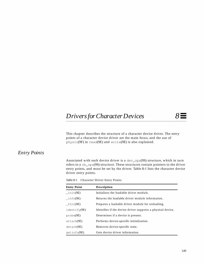
149
Drivers for Character Devices 8
This chapter describes the structure of a character device driver. The entrypoints of a character device driver are the main focus, and the use ofphysio (9F) in read (9E) and write (9E) is also explained.
Entry PointsAssociated with each device driver is a dev_ops (9S) structure, which in turnrefers to a cb_ops (9S) structure. These structures contain pointers to the driverentry points, and must be set by the driver. Table 8-1 lists the character devicedriver entry points.
Table 8-1 Character Driver Entry Points
Entry Point Description
_init (9E) Initializes the loadable driver module.
_info (9E) Returns the loadable driver module information.
_fini (9E) Prepares a loadable driver module for unloading.
identify (9E) Identifies if the device driver supports a physical device.
probe (9E) Determines if a device is present.
attach (9E) Performs device-specific initialization.
detach (9E) Removes device-specific state.
getinfo (9E) Gets device driver information.

150 Writing Device Drivers—August, 1994
8
Note – Some of these entry points may be replaced by nodev (9F) ornulldev (9F) as appropriate.
AutoconfigurationThe attach (9E) routine should perform the common initialization tasks thatall devices require. Typically, these tasks include:
• Allocating per-instance state structures• Mapping the device’s registers• Registering device interrupts• Initializing mutex and condition variables• Creating minor nodes
Character device drivers create minor nodes of type S_IFCHR. This causes acharacter special file representing the node to eventually appear in the/devices hierarchy.
Code Example 8-1 Character driver attach (9E) routine
static intxxattach(dev_info_t *dip, ddi_attach_cmd_t cmd){
open (9E) Gains access to a device.
close (9E) Relinquishes access to a device.
read (9E) Read data from device.
write (9E) Write data to device.
ioctl (9E) Perform arbitrary operation.
prop_op (9E) Manages arbitrary driver properties.
mmap(9E) Checks virtual mapping for a memory mapped device.
segmap(9E) Maps device memory into user space.
chpoll (9E) Poll device for events.
Table 8-1 Character Driver Entry Points
Entry Point Description
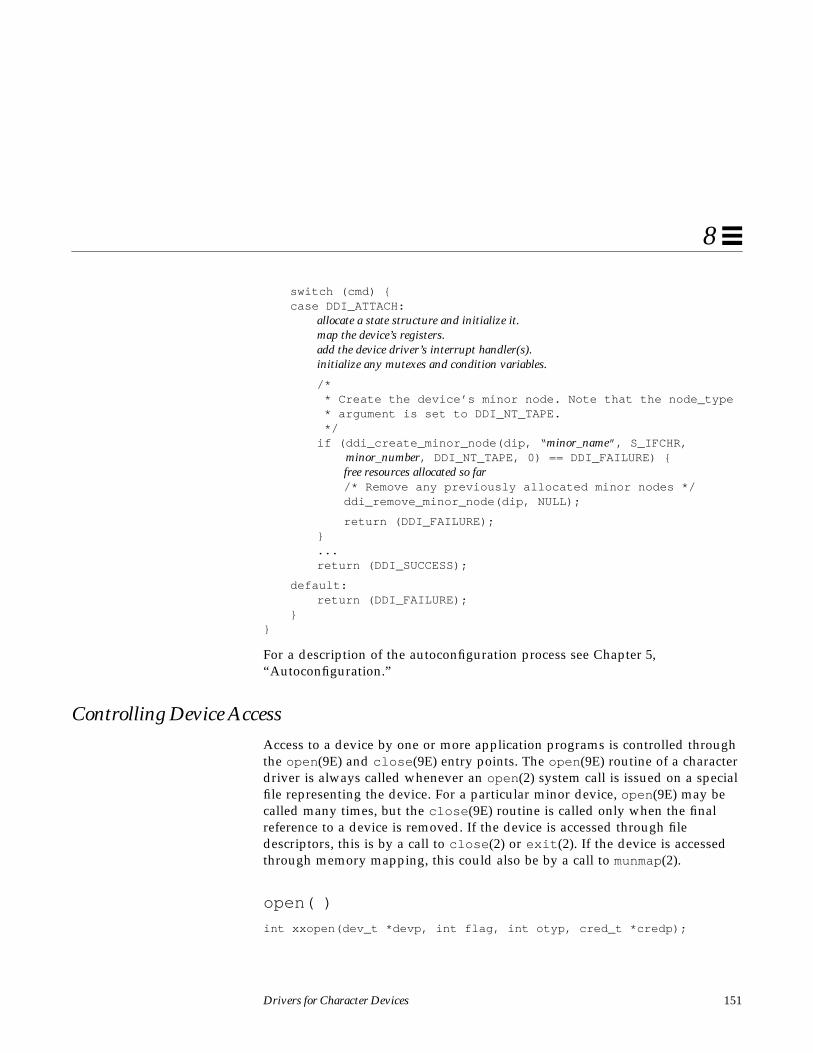
Drivers for Character Devices 151
8
switch (cmd) {case DDI_ATTACH:
allocate a state structure and initialize it.map the device’s registers.add the device driver’s interrupt handler(s).initialize any mutexes and condition variables.
/* * Create the device’s minor node. Note that the node_type * argument is set to DDI_NT_TAPE. */if (ddi_create_minor_node(dip, “ minor_name”, S_IFCHR,
minor_number, DDI_NT_TAPE, 0) == DDI_FAILURE) {free resources allocated so far/* Remove any previously allocated minor nodes */ddi_remove_minor_node(dip, NULL);
return (DDI_FAILURE);}...return (DDI_SUCCESS);
default:return (DDI_FAILURE);
}}
For a description of the autoconfiguration process see Chapter 5,“Autoconfiguration.”
Controlling Device AccessAccess to a device by one or more application programs is controlled throughthe open (9E) and close (9E) entry points. The open (9E) routine of a characterdriver is always called whenever an open (2) system call is issued on a specialfile representing the device. For a particular minor device, open (9E) may becalled many times, but the close (9E) routine is called only when the finalreference to a device is removed. If the device is accessed through filedescriptors, this is by a call to close (2) or exit (2). If the device is accessedthrough memory mapping, this could also be by a call to munmap(2).
open( )
int xxopen(dev_t *devp, int flag, int otyp, cred_t *credp);
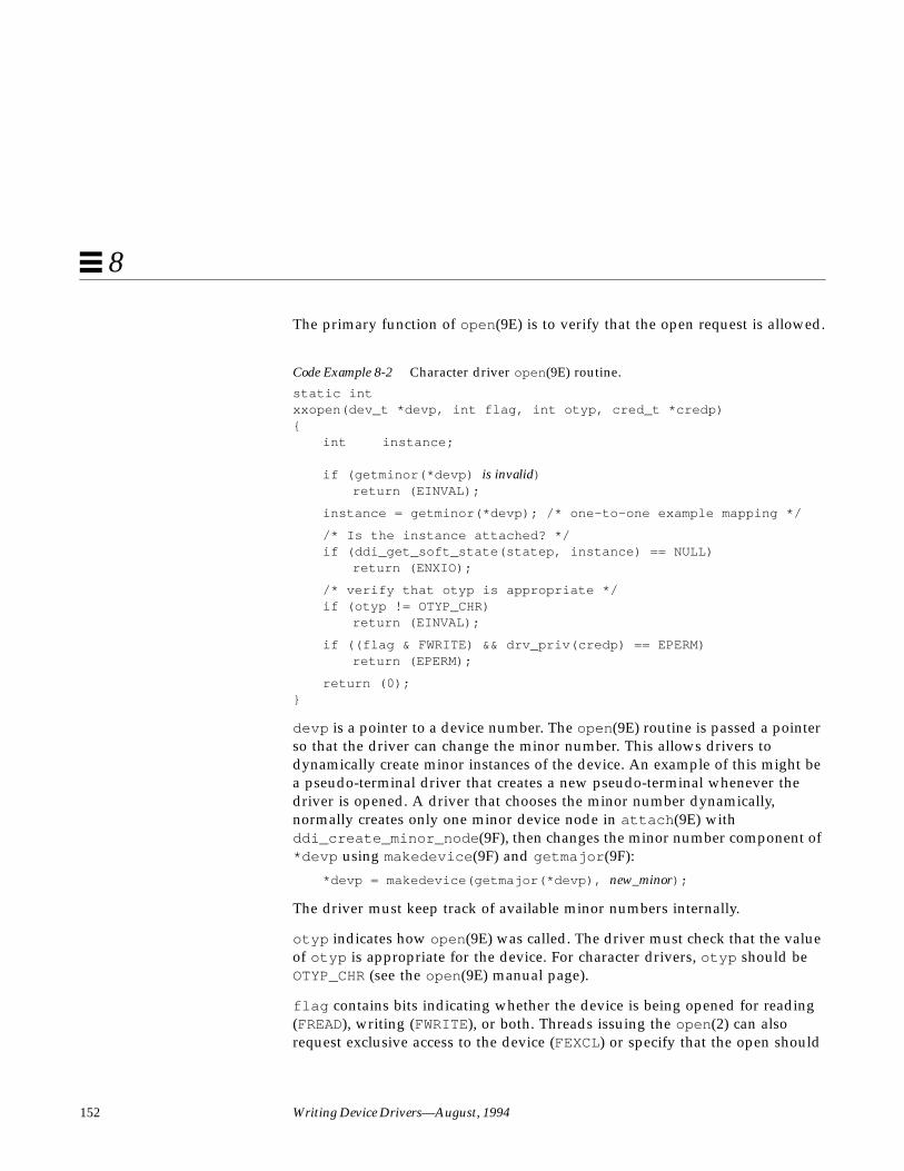
152 Writing Device Drivers—August, 1994
8
The primary function of open (9E) is to verify that the open request is allowed.
Code Example 8-2 Character driver open (9E) routine.
static intxxopen(dev_t *devp, int flag, int otyp, cred_t *credp){
int instance;
if (getminor(*devp) is invalid)return (EINVAL);
instance = getminor(*devp); /* one-to-one example mapping */
/* Is the instance attached? */if (ddi_get_soft_state(statep, instance) == NULL)
return (ENXIO);
/* verify that otyp is appropriate */if (otyp != OTYP_CHR)
return (EINVAL);
if ((flag & FWRITE) && drv_priv(credp) == EPERM)return (EPERM);
return (0);}
devp is a pointer to a device number. The open (9E) routine is passed a pointerso that the driver can change the minor number. This allows drivers todynamically create minor instances of the device. An example of this might bea pseudo-terminal driver that creates a new pseudo-terminal whenever thedriver is opened. A driver that chooses the minor number dynamically,normally creates only one minor device node in attach (9E) withddi_create_minor_node (9F), then changes the minor number component of*devp using makedevice (9F) and getmajor (9F):
*devp = makedevice(getmajor(*devp), new_minor);
The driver must keep track of available minor numbers internally.
otyp indicates how open (9E) was called. The driver must check that the valueof otyp is appropriate for the device. For character drivers, otyp should beOTYP_CHR (see the open (9E) manual page).
flag contains bits indicating whether the device is being opened for reading(FREAD), writing (FWRITE), or both. Threads issuing the open (2) can alsorequest exclusive access to the device (FEXCL) or specify that the open should

Drivers for Character Devices 153
8
not block for any reason (FNDELAY), but it is up to the driver to enforce bothcases. A driver for a write-only device such as a printer might consider anopen for reading invalid.
credp is a pointer to a credential structure containing information about thecaller, such as the user ID and group IDs. Drivers should not examine thestructure directly, but should instead use drv_priv (9F) to check for thecommon case of root privileges. In this example, only root is allowed toopen the device for writing.
close( )
int xxclose(dev_t dev, int flag, int otyp, cred_t *credp);
close (9E) should perform any cleanup necessary to finish using the minordevice, and prepare the device (and driver) to be opened again. For example,the open routine might have been invoked with the exclusive access (FEXCL)flag. A call to close (9E) would allow further opens to continue. Otherfunctions that close (9E) might perform are:
• Wait for I/O to drain from output buffers before returning.
• Rewind a tape (tape device).
• Hang up the phone line (modem device).
I/O Request HandlingThis section gives the details of I/O request processing: from the application tothe kernel, the driver, the device, the interrupt handler, and back to the user.
User Addresses
When a thread issues a write (2) system call, it passes the address of a bufferin user space:
char buffer[] = “python”;
count = write(fd, buffer, strlen(buffer) + 1);

154 Writing Device Drivers—August, 1994
8
The system builds a uio (9S) structure to describe this transfer by allocating aniovec (9S) structure and setting the iov_base field to the address passed towrite (2); in this case, buffer . The uio (9S) structure is what is passed to thedriver write(9E) routine (see “Vectored I/O” for more information about theuio (9S) structure).
A problem is that this address is in user space, not kernel space, and so is notguaranteed to be currently in memory. It is not even guaranteed to be a validaddress. In either case, accessing a user address directly could crash thesystem, so device drivers should never access user addresses directly. Instead,they should always use one of the data transfer routines in the Solaris 2.xDDI/DKI that transfer data into or out of the kernel; see “Copying Data” onpage 313 and “uio(9S) Handling” on page 352 for a summary of the availableroutines. These routines are able to handle page faults, either by bringing theproper user page in and continuing the copy transparently, or by returning anerror on an invalid access.
Two routines commonly used are copyout (9F) to copy data from the driver touser space, and copyin (9F) to copy data from user space to the driver.ddi_copyout (9F) and ddi_copyin (9F) operate similarly but are to be used inthe ioctl (9E) routine. copyin (9F) and copyout (9F) can be used on the bufferdescribed by each iovec (9S) structure, or uiomove (9F) can perform the entiretransfer to or from a contiguous area of driver (or device) memory.
Vectored I/O
In character drivers, transfers are described by a uio (9S) structure. Theuio (9S) structure contains information about the direction and size of thetransfer, plus an array of buffers describing one end of the transfer (the otherend is the device). Below is a list of uio (9S) structure members that areimportant to character drivers.
iovec_t *uio_iov; /* base address of the iovec buffer *//* description array */
int uio_iovcnt; /* the number of iovec structures */off_t uio_offset; /* offset into device where data is */
/* transferred from or to */offset_t uio_loffset/* 64-bit offset into file where data */
/* is transferred from or to. See NOTES.*/int uio_resid; /* amount (in bytes) not transferred on */
/* completion */
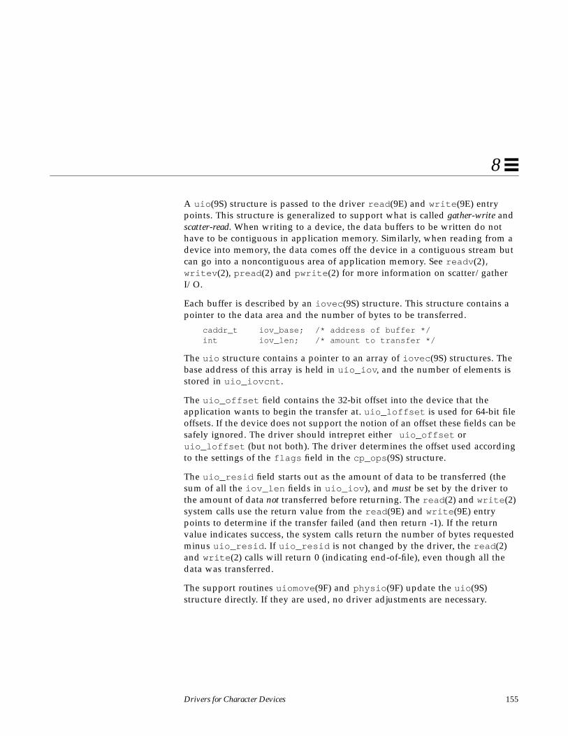
Drivers for Character Devices 155
8
A uio (9S) structure is passed to the driver read (9E) and write (9E) entrypoints. This structure is generalized to support what is called gather-write andscatter-read. When writing to a device, the data buffers to be written do nothave to be contiguous in application memory. Similarly, when reading from adevice into memory, the data comes off the device in a contiguous stream butcan go into a noncontiguous area of application memory. See readv (2),writev (2), pread (2) and pwrite (2) for more information on scatter/gatherI/O.
Each buffer is described by an iovec (9S) structure. This structure contains apointer to the data area and the number of bytes to be transferred.
caddr_t iov_base; /* address of buffer */int iov_len; /* amount to transfer */
The uio structure contains a pointer to an array of iovec (9S) structures. Thebase address of this array is held in uio_iov , and the number of elements isstored in uio_iovcnt .
The uio_offset field contains the 32-bit offset into the device that theapplication wants to begin the transfer at. uio_loffset is used for 64-bit fileoffsets. If the device does not support the notion of an offset these fields can besafely ignored. The driver should intrepret either uio_offset oruio_loffset (but not both). The driver determines the offset used accordingto the settings of the flags field in the cp_ops (9S) structure.
The uio_resid field starts out as the amount of data to be transferred (thesum of all the iov_len fields in uio_iov ), and must be set by the driver tothe amount of data not transferred before returning. The read (2) and write (2)system calls use the return value from the read (9E) and write (9E) entrypoints to determine if the transfer failed (and then return -1). If the returnvalue indicates success, the system calls return the number of bytes requestedminus uio_resid . If uio_resid is not changed by the driver, the read (2)and write (2) calls will return 0 (indicating end-of-file), even though all thedata was transferred.
The support routines uiomove (9F) and physio (9F) update the uio (9S)structure directly. If they are used, no driver adjustments are necessary.

156 Writing Device Drivers—August, 1994
8
Driver Operations
The read (9E) or write (9E) entry point is called when a user thread issues thecorresponding system call. It is the responsibility of these routines to performthe desired transfer, then return an indication of success or failure.
Programmed I/O Transfers.
Programmed I/O (PIO) devices rely on the CPU to perform the data transfer.PIO data transfers are identical to other device register read and writeoperations. An assignment statement is used to move a value from onevariable or structure to another.
uiomove( )
This kind of device may allow the driver to use uiomove (9F). uiomove (9F)transfers data between the user space (defined by the uio (9S) structure) andthe kernel. uiomove (9F) can handle page faults so the memory to which data istransferred need not be locked down. It also updates the uio_resid field inthe uio (9S) structure. The following example is one way to write the ramdiskread (9E) routine, and relies on the following fields being present in theramdisk state structure:
caddr_t ram; /* base address of ramdisk */int ramsize; /* size of the ramdisk */
Code Example 8-3 Ramdisk read (9E) routine using uiomove (9F)
static intrd_read(dev_t dev, struct uio *uiop, cred_t *credp){
int instance;rd_devstate_t *rsp;
instance = getminor(dev);rsp = ddi_get_soft_state(rd_statep, instance);if (rsp == NULL)
return (ENXIO);if (uiop->uio_offset >= rsp->ramsize)
return (EINVAL);
/* * uiomove takes the offset into the kernel buffer, * the data transfer count (minimum of the requested and * the remaining data), the UIO_READ flag, and a pointer

Drivers for Character Devices 157
8
* to the uio structure. */return (uiomove(rsp->ram + uiop->uio_offset,
min(uiop->uio_resid, rsp->ramsize - uiop->uio_offset),UIO_READ, uiop));
}
uwritec( ) and ureadc( )
Another example might be a driver writing data directly to the device’smemory, which must be performed one byte at a time. Each byte is retrievedfrom the uio (9S) structure using uwritec (9F), then sent to the device.read (9E) can use ureadc (9F) to transfer a byte from the device to the areadescribed by the uio (9S) structure.Code Example 8-4 Programmed I/O write (9E) routine using uwritec (9F).
static intxxwrite(dev_t dev, struct uio *uiop, cred_t *credp){
int instance;int value;struct xxstate *xsp;struct device_reg *regp;
instance = getminor(dev);xsp = ddi_get_soft_state(statep, instance);if (xsp == NULL)
return (ENXIO);
regp = xsp->regp;while (uiop->uio_resid > 0) {
/* * do the PIO access */value = uwritec(uiop);if (value == -1)
return (EFAULT);regp->data = (u_char)value;regp->csr = START_TRANSFER;/* this device requires a ten microsecond delay *//* between writes */drv_usecwait(10);
}return (0);
}

158 Writing Device Drivers—August, 1994
8
DMA Transfers
Many character drivers (especially those with DMA capabilities) usephysio (9F) to do most of the work.
int physio(int (*strat)(struct buf *), struct buf *bp,dev_t dev, int rw, void (*mincnt)(struct buf *),struct uio *uio);
physio (9F) requires the driver to provide a strategy (9E) entry point (thoughit does not get placed in the cb_ops (9S) structure). physio (9F) ensures thatmemory space is locked down (cannot be paged out) for the duration of thedata transfer. This is necessary for DMA transfers because they cannot handlepage faults. physio (9F) also provides an automated way of breaking a largertransfer into a series of smaller, more manageable ones.
Code Example 8-5 read (9E) and write (9E) routines using physio (9F)
static intxxread(dev_t dev, struct uio *uiop, cred_t *credp){
int instance;struct xxstate *xsp;
instance = getminor(dev);xsp = ddi_get_soft_state(statep, instance);
if (xsp == NULL)return (ENXIO);
return (physio(xxstrategy, NULL, dev, B_READ, xxminphys, uiop));}
static intxxwrite(dev_t dev, struct uio *uiop, cred_t *credp){
int instance;struct xxstate *xsp;
instance = getminor(dev);xsp = ddi_get_soft_state(statep, instance);
if (xsp == NULL)return (ENXIO);
return (physio(xxstrategy, NULL, dev, B_WRITE, xxminphys,uiop));}
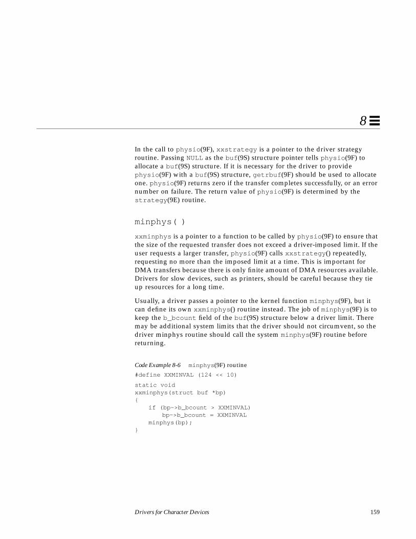
Drivers for Character Devices 159
8
In the call to physio (9F), xxstrategy is a pointer to the driver strategyroutine. Passing NULL as the buf (9S) structure pointer tells physio (9F) toallocate a buf (9S) structure. If it is necessary for the driver to providephysio (9F) with a buf (9S) structure, getrbuf (9F) should be used to allocateone. physio (9F) returns zero if the transfer completes successfully, or an errornumber on failure. The return value of physio (9F) is determined by thestrategy (9E) routine.
minphys( )
xxminphys is a pointer to a function to be called by physio (9F) to ensure thatthe size of the requested transfer does not exceed a driver-imposed limit. If theuser requests a larger transfer, physio (9F) calls xxstrategy () repeatedly,requesting no more than the imposed limit at a time. This is important forDMA transfers because there is only finite amount of DMA resources available.Drivers for slow devices, such as printers, should be careful because they tieup resources for a long time.
Usually, a driver passes a pointer to the kernel function minphys (9F), but itcan define its own xxminphys () routine instead. The job of minphys (9F) is tokeep the b_bcount field of the buf (9S) structure below a driver limit. Theremay be additional system limits that the driver should not circumvent, so thedriver minphys routine should call the system minphys (9F) routine beforereturning.
Code Example 8-6 minphys (9F) routine
#define XXMINVAL (124 << 10)
static voidxxminphys(struct buf *bp){
if (bp->b_bcount > XXMINVAL)bp->b_bcount = XXMINVAL
minphys(bp);}

160 Writing Device Drivers—August, 1994
8
strategy( )
The strategy (9E) routine originated in block drivers and is so called becauseit can implement a strategy for efficient queuing of I/O requests to a blockdevice. A driver for a character-oriented device can also use a strategy (9E)routine. In the character I/O model presented here, strategy (9E) does notmaintain a queue of requests, but rather services one request at a time.
In this example, the strategy (9E) routine for a character-oriented DMAdevice allocates DMA resources for the data transfer and starts the commandby programming the device register (see Chapter 7, “DMA,” for a detaileddescription). Note that strategy (9E) does not receive a device number(dev_t ) as a parameter, this is instead retrieved from the b_edev field of thebuf (9S) structure.
Code Example 8-7 strategy (9E) routine supporting physio (9F)
static intxxstrategy(struct buf *bp){
int instance;struct xxstate *xsp;ddi_dma_cookie_t cookie;
instance = getminor(bp->b_edev);xsp = ddi_get_soft_state(statep, instance);...set up DMA resources with ddi_dma_buf_setup(9F)
xsp->bp = bp; /* remember bp */
program DMA engine and start command
return (0);}
Though strategy (9E) is declared to return an int , it should always returnzero. strategy (9E) indicates an error to physio (9F) by setting the B_ERRORbit in the b_flags member of the buf (9S) structure, and placing theappropriate error number in the b_error field. physio (9F) will then returnzero to indicate success, or the value of the b_error field if an error occurs.
Drivers for Character Devices 161
8
After calling strategy (9E), physio (9F) waits until the driver finishes withthe buf (9S) structure (the transfer fails or is complete) by calling biowait (9F).A call to biodone (9F) must later be made by the driver or physio (9F) willwait forever. For example, strategy (9E) must call biodone (9F) when anerror occurs.
Transfer Completion
On completion of the DMA transfer, the device generates an interrupt.Eventually, the interrupt routine will be called. In this example, xxintr ()receives a pointer to the state structure for the device that might have issuedthe interrupt. The most important function in the interrupt routine is to notifyphysio (9F) that the transfer is complete, which is accomplished by the call tobiodone (9F). If the driver does not notify physio (9F) that the transfer iscomplete, physio (9F) will not return, and the thread will hang.
Code Example 8-8 Interrupt routine using physio (9F)
static u_intxxintr(caddr_t arg){
struct xxstate *xsp = (struct xxstate *)arg;
if ( device did not interrupt) {return (DDI_INTR_UNCLAIMED);
}
if ( error) {error handling
}
release any resources used in the transfer, such as DMA resources (ddi_dma_free(9F))
/* wake up waiting thread in physio(9F) */biodone (xsp->bp);
return (DDI_INTR_CLAIMED);}
Mapping Device MemorySome devices, such as frame buffers, have memory that is directly accessible touser threads by way of memory mapping. Drivers for these devices typicallydo not support the read (9E) and write (9E) interfaces. Instead, these drivers
162 Writing Device Drivers—August, 1994
8
support memory mapping with the mmap(9E) entry point. A typical example isa frame buffer driver that implements the mmap(9E) entry point to allow theframe buffer to be mapped in a user thread.
segmap( )
int xxsegmap(dev_t dev, off_t off, struct as *asp, caddr_t *addrp,off_t len, unsigned int prot, unsigned int maxprot,unsigned int flags, cred_t *credp);
segmap(9E) is the entry point responsible for actually setting up a memorymapping requested by the system on behalf of an mmap(2) system call. Driversfor all memory mapped devices usually use ddi_segmap (9F) as the entrypoint rather than define their own segmap(9E) routine.
mmap( )
int xxmmap(dev_t dev, off_t off, int prot);
This routine is called as a result of an mmap(2) system call, and also as theresult of a page fault. mmap(9E) is called to translate the device offset off tothe corresponding page frame number. Code Example 8-9 allows a user threadto memory map the device registers.
Code Example 8-9 mmap(9E) routine
static intxxmmap(dev_t dev, off_t off, int prot){
int instance;struct xxstate *xsp;
if (prot & PROT_WRITE)return (-1);
instance = getminor(dev);xsp = ddi_get_soft_state(statep, instance);if (xsp == NULL)
return (-1);
if ( off is invalid)return (-1);
return (hat_getkpfnum(xsp->regp->csr + off));}
Drivers for Character Devices 163
8
dev is the device number and off is the offset into the device’s memory. protspecifies the kind of access requested, such as PROT_READ and PROT_WRITE Avalue of PROT_WRITE for prot would be invalid on a read-only device. Seemmap(9E) and mmap(2).
hat_getkpfnum (9F) returns the page frame number for the memory thatshould be mapped. xsp->regp->csr is the kernel virtual address of thedevice memory determined in attach (9E) by calling ddi_map_regs (9F) andstored in the state structure.
In Code Example 8-9 the whole address range up to off must be mappedusing ddi_map_regs (9F). This can use a lot of system resources for devicesthat have a large mappable memory area, and is a waste of resources if thedriver only needs the mapping so it can call hat_getkpfnum (9F). A betterway to get the page frame number for a given offset is to just map thatindividual page, retrieve the page frame number, then unmap the page beforereturning. Since the page frame number refers to a page on the device, it willnot change when the page is unmapped.
Code Example 8-10 mmap(9E) routine using less resources.
static intxxmmap(dev_t dev, off_t off, int prot){
int kpfn = -1;caddr_t kva;
...
if (ddi_map_regs(xsp->dip, rnumber, &kva, off, ptob(1)) ==DDI_SUCCESS) {kpfn = hat_getkpfnum(kva);ddi_unmap_regs(xsp->dip, rnumber, &kva, off, ptob(1));
}
return (kpfn);}
If the mappable memory of the device is physically contiguous, converting offto the number of pages and adding it to the base page frame number will givethe same result as getting the page frame number of a mapped page. In thiscase, only the first page of the device’s memory needs to be mapped:
return (hat_getkpfnum(xsp->regp->csr) + btop(off));
For an example showing how to access a memory mapped device from a userprogram see “Using Existing Drivers” on page 243.

164 Writing Device Drivers—August, 1994
8
Multiplexing I/O on File DescriptorsA thread sometimes wants to handle I/O on more than one file descriptor. Oneexample is an application program that wants to read the temperature from atemperature sensing device and then report the temperature to an interactivedisplay. If the program makes a read request and there is no data available, itshould not block waiting for the temperature before interacting with the useragain.
The poll (2) system call provides users with a mechanism for multiplexingI/O over a set of file descriptors that reference open files. poll (2) identifiesthose files on which a program can send or receive data without blocking, oron which certain events have occurred.
To allow a program to poll a character driver, the driver must implement thechpoll (9E) entry point.
State Structure
This section adds the following field to the state structure. See “State Structure”on page 57 for more information.
struct pollhead pollhead; /* for chpoll(9E)/pollwakeup(9F) */
chpoll( )
int xxchpoll(dev_t dev, short events, int anyyet, short *reventsp,struct pollhead **phpp);
The system calls chpoll (9E) when a user process issues a poll (2) system callon a file descriptor associated with the device. The chpoll (9E) entry pointroutine is used by non-STREAMS character device drivers that wish to supportpolling.
In chpoll (9E), the driver must follow the following rules:
• Implement the following algorithm when the chpoll (9E) entry point iscalled:
if ( events are satisfied now) {*reventsp = mask of satisfied events;
} else {*reventsp = 0;if (!anyyet)

Drivers for Character Devices 165
8
*phpp = & local pollhead structure;}return (0);
xxchpoll ( ) should check to see if certain events have occurred; seechpoll (9E). It should then return the mask of satisfied events by setting thereturn events in *reventsp .
If no events have occurred, the return field for the events is cleared. If theanyyet field is not set, the driver must return an instance of the pollheadstructure. It is usually allocated in a state structure and should be treated asopaque by the driver. None of its fields should be referenced.
• Call pollwakeup (9F) whenever a device condition of type events , listed inCode Example 8-11, occurs. This function should be called only with oneevent at a time. pollwakeup (9F) might be called in the interrupt routinewhen the condition has occurred.
The following two examples show how to implement the polling disciplineand how to use pollwakeup (9F).
Code Example 8-11 chpoll (9E) routine
static intxxchpoll(dev_t dev, short events, int anyyet,
short *reventsp,struct pollhead **phpp){
int instance;u_char status;short revent;struct xxstate *xsp;
instance = getminor(dev);xsp = ddi_get_soft_state(statep, instance);if (xsp == NULL)
return (ENXIO);
revent = 0;/* * Valid events are: * POLLIN | POLLOUT | POLLPRI | POLLHUP | POLLERR * This example checks only for POLLIN and POLLERR. */status = xsp->regp->csr;

166 Writing Device Drivers—August, 1994
8
if ((events & POLLIN) && data available to read) {revent |= POLLIN;
}if ((events & POLLERR) && (status & DEVICE_ERROR)) {
revent |= POLLERR;}
/* if nothing has occurred */if (revent == 0) {
if (!anyyet) {*phpp = &xsp->pollhead;
}}*reventsp = revent;return (0);
}
In this example, the driver can handle the POLLIN and POLLERR events (seechpoll (9E) for a detailed discussion of the available events). The driver firstreads the status register to determine the current state of the device. Theparameter events specifies which conditions the driver should check. If theappropriate conditions have occurred, the driver sets that bit in *reventsp . Ifnone of the conditions have occurred and anyyet is not set, the address of thepollhead structure is returned in *phpp .
Code Example 8-12 Interrupt routine supporting chpoll (9E)
static u_intxxintr(caddr_t arg){
struct xxstate *xsp = (struct xxstate *) arg;u_char status, temp;
normal interrupt processing...status = xsp->regp->csr;if (status & DEVICE_ERROR) {
pollwakeup(&xsp->pollhead, POLLERR);}if ( just completed a read) {
pollwakeup(&xsp->pollhead, POLLIN);}...return (DDI_INTR_CLAIMED);
}

Drivers for Character Devices 167
8
pollwakeup (9F) is usually called in the interrupt routine when a supportedcondition has occurred. The interrupt routine reads the status from the statusregister and checks for the conditions. It then calls pollwakeup (9F) for eachevent to possibly notify polling threads that they should check again. Note thatpollwakeup (9F) should not be called with any locks held, since it could causethe chpoll (9E) routine to be entered, causing deadlock if that routine tries tograb the same lock.
Miscellaneous I/O ControlThe ioctl (9E) routine is called when a user thread issues an ioctl (2) systemcall on a file descriptor associated with the device. The I/O control mechanismis a catchall for getting and setting device-specific parameters. It is frequentlyused to set a device specific mode, either by setting internal driver softwareflags or by writing commands to the device. It can also be used to returninformation to the user about the current device state. In short, it can dowhatever the application and driver need it to do.
ioctl(9E)
int xxioctl(dev_t dev, int cmd, int arg, int mode,cred_t *credp, int *rvalp);
The cmd parameter indicates which command ioctl (9E) should perform. Byconvention, I/O control commands indicate the driver they belong to in bits 8-15 of the command (usually given by the ASCII code of a characterrepresenting the driver), and the driver-specific command in bits 0-7. They areusually created in the following way:
#define XXIOC (‘x’ << 8)
#define XX_GET_STATE (XXIOC | 1) /* get status register */#define XX_SET_CMD (XXIOC | 2) /* send command */
The interpretation of arg depends on the command. I/O control commandsshould be documented (in the driver documentation, or a manual page) anddefined in a public header file, so that applications know the names, what theydo, and what they accept or return as arg . Any data transfer of arg (into orout of the driver) must be performed by the driver.
ioctl (9E) is usually a switch statement with a case for each supportedioctl (9E) request.

168 Writing Device Drivers—August, 1994
8
Code Example 8-13 ioctl (9E) routine
static intxxioctl(dev_t dev, int cmd, int arg, int mode,
cred_t *credp,int *rvalp){
int instance;u_char csr;struct xxstate *xsp;
instance = getminor(dev);xsp = ddi_get_soft_state(statep, instance);if (xsp == NULL) {
return (ENXIO);}switch (cmd) {case XX_GET_STATUS:
csr = xsp->regp->csr;if (ddi_copyout(&csr, (caddr_t) arg, sizeof(u_char),
mode) != 0) {return (EFAULT);
}break;
case XX_SET_CMD:if (ddi_copyin((caddr_t) arg, &csr, sizeof(u_char),
mode) != 0) {return (EFAULT);
}xsp->regp->csr = csr;break;
default:/* generic “ioctl unknown” error */return (ENOTTY);
}return (0);
}
The cmd variable identifies a specific device control operation. If arg containsa user virtual address, ioctl (9E) must call ddi_copyin (9F) orddi_copyout (9F) to transfer data between the data structure in theapplication program pointed to by arg and the driver. In Code Example 8-13,for the case of an XX_GET_STATUS request the contents of xsp->regp->csris copied to the address in arg . When a request succeeds, ioctl (9E) can storein *rvalp any integer value to be the return value of the ioctl (2) system call

Drivers for Character Devices 169
8
that made the request. Negative return values, such as -1, should be avoided,as they usually indicate the system call failed, and many application programsassume negative values indicate failure.
An application that uses the I/O controls above could look like the following:
Code Example 8-14 Using ioctl (2)
#include <sys/types.h>#include “xxio.h”
int main(void){
u_char status;......./* * read the device status */if (ioctl(fd, XX_GET_STATUS, &status) == -1) {
/* error handling */}printf("device status %x\n", status);exit(0);
}

170 Writing Device Drivers—August, 1994
8

171
Drivers for Block Devices 9
This chapter describes the structure of block device drivers. The kernel views ablock device as a set of randomly accessible logical blocks. The file systembuffers the data blocks between a block device and the user space using a listof buf (9S) structures. Only block devices can support a file system. Forinformation on writing disk drivers that support SunOS disk commands (suchas format (1M)) see Appendix B, “Advanced Topics.”
File I/OA file system is a tree-structured hierarchy of directories and files. Some filesystems, such as the UNIX File System (UFS), reside on block-oriented devices.File systems are created by mkfs (1M) and newfs (1M).
When an application issues a read (2) or write (2) system call to an ordinaryfile on the UFS file system, the file system may call the device driverstrategy (9E) entry point for the block device on which the file resides. Thefile system code may call strategy (9E) several times for a single read (2) orwrite (2) system call.
It is the file system code that determines the logical device address, or logicalblock number, for each block and builds a block I/O request in the form of abuf (9S) structure. The driver strategy (9E) entry point then interprets thebuf (9S) structure and completes the request.

172 Writing Device Drivers—August, 1994
9
State StructureThis chapter adds the following fields to the state structure. See “StateStructure” on page 57 for more information.
int nblocks; /* size of device */int open; /* flag indicating device is open */int nlayered; /* count of layered opens */struct buf *list_head; /* head of transfer request list */struct buf *list_tail; /* tail of transfer request list */
Entry PointsAssociated with each device driver is a dev_ops (9S) structure, which in turnrefers to a cb_ops (9S) structure. See Chapter 5, “Autoconfiguration,” fordetails regarding driver data structures. Table 9-1 lists the block driver entrypoints.
Table 9-1 Block Driver Entry Points
Entry Point Description
_init (9E) Initialize a loadable driver module.
_info (9E) Return information on a loadable driver module.
_fini (9E) Prepare a loadable driver module for unloading.
identify (9E) Determine if the device driver supports a given physical device.
probe (9E) Determine if a device is present.
attach (9E) Perform device-specific initialization.
detach (9E) Remove device-specific state.
getinfo (9E) Get device driver information.
dump(9E) Dump memory to the device during system failure.
open (9E) Gain access to a device.
close (9E) Relinquish access to a device.
prop_op (9E) Manage arbitrary driver properties.
print (9E) Print error message on driver failure.
strategy (9E) I/O interface for block data.

Drivers for Block Devices 173
9
Note – Some of the above entry points may be replaced by nodev (9F) ornulldev (9F) as appropriate.
Autoconfigurationattach (9E) should perform the common initialization tasks for each instanceof a device. Typically, these tasks include:
• Allocating per-instance state structures• Mapping the device’s registers• Registering device interrupts• Initializing mutex and condition variables• Creating minor nodes
Block device drivers create minor nodes of type S_IFBLK . This causes a blockspecial file representing the node to eventually appear in the /deviceshierarchy.
Logical device names for block devices appear in the /dev/dsk directory, andconsist of a controller number, bus-address number, disk number, and slicenumber. These names are created by the disks (1M) program if the node typeis set to DDI_NT_BLOCK or DDI_NT_BLOCK_CHAN. DDI_NT_BLOCK_CHANshould be specified if the device communicates on a channel (a bus with anadditional level of addressability), such as SCSI disks, and causes a bus-address field (tN) to appear in the logical name. DDI_NT_BLOCK should beused for most other devices.
For each minor device (which corresponds to each partition on the disk), thedriver must also create an nblocks property. This is an integer propertygiving the number of blocks supported by the minor device expressed in unitsof DEV_BSIZE (512 bytes). The file system uses the nblocks property todetermine device limits. See “Properties” on page 59 for details.
Code Example 9-1 shows a typical attach (9E) entry point with emphasis oncreating the device’s minor node and the nblocks property.
Code Example 9-1 Block driver attach (9E) routine
static intxxattach(dev_info_t *dip, ddi_attach_cmd_t cmd){

174 Writing Device Drivers—August, 1994
9
switch (cmd) {case DDI_ATTACH:
allocate a state structure and initialize itmap the devices registersadd the device driver’s interrupt handler(s)initialize any mutexs and condition variablesread label information if the device is a disk
/* * Create the devices minor node. Note that the node_type * argument is set to DDI_NT_BLOCK. */if (ddi_create_minor_node(dip, “ minor_name”, S_IFBLK,
minor_number, DDI_NT_BLOCK, 0) == DDI_FAILURE) {free resources allocated so far/* Remove any previously allocated minor nodes */ddi_remove_minor_node(dip, NULL);return (DDI_FAILURE);
}
/* * Create driver properties like “nblocks”. If the device * is a disk, the nblocks property is usually calculated from * information in the disk label. */xsp->nblocks = size of device in 512 byte blocks;if (ddi_prop_create(makedevice(DDI_MAJOR_T_UNKNOWN,
instance), dip, DDI_PROP_CANSLEEP,“nblocks”, (caddr_t)&xsp->nblocks, sizeof (int))!= DDI_PROP_SUCCESS) {cmn_err(CE_CONT, “%s: cannot create nblocks property\n”,
ddi_get_name(dip));free resources allocated so farreturn (DDI_FAILURE);
}
xsp->open = 0;xsp->nlayered = 0;
...return (DDI_SUCCESS);
default:return (DDI_FAILURE);
}}

Drivers for Block Devices 175
9
Properties are associated with device numbers. In Code Example 9-1,attach (9E) builds a device number using makedevice (9F). At this point,however, only the minor number component of the device number is known,so it must use the special major number DDI_MAJOR_T_UNKNOWN to build thedevice number.
Controlling Device AccessThis section describes aspects of the open (9E) and close (9E) entry points thatare specific to block device drivers. See Chapter 8, “Drivers for CharacterDevices,” for more information on open (9E) and close (9E).
open( )
int xxopen(dev_t *devp, int flag, int otyp, cred_t *credp)
The open (9E) entry point is used to gain access to a given device. The open(9E)routine of a block driver is called when a user thread issues an open (2) ormount (2) system call on a block special file associated with the minor device,or when a layered driver calls open(9E). See “File I/O” on page 171 for moreinformation.
The open (9E) entry point should make the following checks:
• The device can be opened: for example, it is on-line and ready.• The device can be opened as requested: the device supports the operation,
and the device’s current state does not conflict with the request.• The caller has permission to open the device.
Code Example 9-2 Block driver open (9E) routine
static intxxopen(dev_t *devp, int flags, int otyp, cred_t *credp){
int instance;struct xxstate *xsp;
instance = getminor(*devp);xsp = ddi_get_soft_state(statep, instance);if (xsp == NULL)
return (ENXIO);

176 Writing Device Drivers—August, 1994
9
mutex_enter(&xsp->mu);/* * only honor FEXCL. If a regular open or a layered open * is still outstanding on the device, the exclusive open * must fail. */if ((flags & FEXCL) && (xsp->open || xsp->nlayered)) {
mutex_exit(&xsp->mu);return (EAGAIN);
}
switch (otyp) {case OTYP_LYR:
xsp->nlayered++;break;
case OTYP_BLK:xsp->open = 1;break;
default:mutex_exit(&xsp->mu);return (EINVAL);
}mutex_exit(&xsp->mu);return (0);
}
The otyp argument is used to specify the type of open on the device.OTYP_BLK is the typical open type for a block device. A device may be openedseveral times with otyp set to OTYP_BLK, though close (9E) will only becalled once the final close of type OTYP_BLK has occurred for the device. otypis set to OTYP_LYR if the device is being used as a layered device. For everyopen of type OTYP_LYR, the layering driver issues a corresponding close oftype OTYP_LYR. The example keeps track of each type of open so the drivercan determine when the device is not being used in close (9E). See theopen (9E) manual page for more details about the otyp argument.
close( )
int xxclose(dev_t dev, int flag, int otyp, cred_t *credp)
The arguments of close (9E) entry point are identical to arguments ofopen (9E), except that dev is the device number, as opposed to a pointer to thedevice number.

Drivers for Block Devices 177
9
The close (9E) routine should verify otyp in the same way as was describedfor the open (9E) entry point. In the example, close (9E) must determine whenthe device can really be closed based on the number of block opens andlayered opens.
Code Example 9-3 Block device close (9E) routine
static intxxclose(dev_t dev, int flag, int otyp, cred_t *credp){
int instance;struct xxstate *xsp;
instance = getminor(dev);xsp = ddi_get_soft_state(statep, instance);if (xsp == NULL)
return (ENXIO);
mutex_enter(&xsp->mu);switch (otyp) {case OTYP_LYR:
xsp->nlayered--;break;
case OTYP_BLK:xsp->open = 0;break;
default:mutex_exit(&xsp->mu);return (EINVAL);
}if (xsp->open || xsp->nlayered) {
/* not done yet */mutex_exit(&xsp->mu);return (0);
}/* cleanup, rewind tape, free memory *//* wait for I/O to drain */mutex_exit(&xsp->mu);
return (0);}

178 Writing Device Drivers—August, 1994
9
Data Transfers
strategy( )
int xxstrategy(struct buf *bp)
The strategy (9E) entry point is used to read and write data buffers to andfrom a block device. The name strategy comes from the fact that this entry pointmay implement some optimal strategy for ordering requests to the device.
strategy (9E) can be written to process one request at a time (synchronoustransfer), or to queue multiple requests to the device (asynchronous transfer).When choosing a method, the abilities and limitations of the device should betaken into account.
The strategy (9E) routine is passed a pointer to a buf (9S) structure. Thisstructure describes the transfer request, and contains status information onreturn. buf (9S) and strategy (9E) are the focus of block device operations.
The buf Structure
Below is a list of buf structure members that are important to block drivers:
int b_flags; /* Buffer Status */struct buf *av_forw; /* Driver work list link */struct buf *av_back; /* Driver work lists link */unsigned int b_bcount; /* # of bytes to transfer */union {
caddr_t b_addr; /* Buffer’s virtual address */} b_un;daddr_t b_blkno; /* Block number on device */diskaddr_t b_lblkno; /* Expanded block number on device */unsigned int b_resid; /* # of bytes not transferred */
/* after error */int b_error; /* Expanded error field */void *b_private; /* “opaque” driver private area */dev_t b_edev; /* expanded dev field */
b_flags contains status and transfer attributes of the buf structure. If B_READis set, the buf structure indicates a transfer from the device to memory,otherwise it indicates a transfer from memory to the device. If the driver
Drivers for Block Devices 179
9
encounters an error during data transfer, it should set the B_ERROR field in theb_flags member and provide a more specific error value in b_error . Driversshould use bioerror (9F) in preference to setting B_ERROR.
Caution – Drivers should never clear b_flags .
av_forw and av_back are pointers that can be used to manage a list of buffersby the driver. See “Asynchronous Data Transfers” on page 184 for a discussionof the av_forw and av_back pointers.
b_bcount specifies the number of bytes to be transferred by the device.
b_un.b_addr is the virtual address of the data buffer when it is mapped intothe kernel.
b_blkno is the starting 32 bit logical block number on the device for the datatransfer, expressed in DEV_BSIZE (512 bytes) units. The driver should useb_blkno or b_lblkno , but not both.
b_lblkno is the starting 64 bit logical block number on the device for the datatransfer, expressed in DEV_BSIZE (512 bytes) units. The driver should useb_blkno or b_lblkno , but not both.
b_resid is set by the driver to indicate the number of bytes that were nottransferred due to an error. See Code Example 9-8 on page 185 for an exampleof setting b_resid . The b_resid member is overloaded: it is also used bydisksort (9F).
b_error is set by the driver an error number when a transfer error occurs. It isset in conjunction with the b_flags B_ERROR bit. See Intro (9E) for detailsregarding error values. Drivers should use bioerror (9F) in preference tosetting b_error directly.
b_private is used exclusivly by the driver to store driver private data.
b_edev contains the device number of the device involved in the transfer.
bp_mapin( )
When a buf structure pointer is passed into the device driver’s strategy (9E)routine, the data buffer referred to by b_un.b_addr is not necessarily mappedin the kernel’s address space. This means that the data is not directly accessible
180 Writing Device Drivers—August, 1994
9
by the driver. Most block-oriented devices have DMA capability, and thereforedo not need to access the data buffer directly. Instead, they use the DMAmapping routines to allow the device’s DMA engine to do the data transfer.For details about using DMA, see Chapter 7, “DMA.”
If a driver needs to directly access the data buffer (as opposed to having thedevice access the data), it must first map the buffer into the kernel’s addressspace using bp_mapin (9F). bp_mapout (9F) should be used when the driver nolonger needs to access the data directly.
Synchronous Data TransfersThis section discusses a simple method for performing synchronous I/Otransfers. It is assumes that the hardware is a simple disk device that cantransfer only one data buffer at a time using DMA. The device driver’sstrategy (9E) routine waits for the current request to complete beforeaccepting a new one. The device interrupts the CPU when the transfercompletes or when an error occurs.
1. Check for invalid buf (9S) requests
Check the buf (9S) structure passed to strategy (9E) for validity. Alldrivers should check to see if:
a. The request begins at a valid block. The driver converts the b_blknofield to the correct device offset and then determines if the offset is validfor the device.
b. The request does not go beyond the last block on the device.
c. Device-specific requirements are met.
If an error is encountered, the driver should indicate the appropriate errorwith bioerror (9F) and complete the request by calling biodone (9F).biodone (9F) notifies the caller of strategy (9E) that the transfer iscomplete (in this case, because of an error).
2. Check if the device is busy
Synchronous data transfers allow single-threaded access to the device. Thedevice driver enforces this by maintaining a busy flag (guarded by a mutex),and by waiting on a condition variable with cv_wait (9F) when the deviceis busy.

Drivers for Block Devices 181
9
If the device is busy, the thread waits until a cv_broadcast (9F) orcv_signal (9F) from the interrupt handler indicates that the device is nolonger busy. See Chapter 4, “Multithreading,” for details on conditionvariables.
When the device is no longer busy, the strategy (9E) routine marks it asbusy and prepares the buffer and the device for the transfer.
3. Set up the buffer for DMA
Prepare the data buffer for a DMA transfer using ddi_dma_buf_setup (9F).See Chapter 7, “DMA,” for information on setting up DMA resources andrelated data structures.
4. Begin the Transfer
At this point, a pointer to the buf (9S) structure is saved in the statestructure of the device. This is so that the interrupt routine can complete thetransfer by calling biodone (9F).
The device driver then accesses device registers to initiate a data transfer. Inmost cases, the driver should protect the device registers from other threadsby using mutexes. In this case, because strategy (9E) is single-threaded,guarding the device registers is not necessary. See Chapter 4,“Multithreading,” for details about data locks.
Once the executing thread has started the device’s DMA engine, the drivercan return execution control to the calling routine.
Code Example 9-4 Synchronous block driver strategy (9E) routine
static intxxstrategy(struct buf *bp){
struct xxstate *xsp;struct device_reg *regp;u_char temp;int instance;ddi_dma_cookie_t cookie;
instance = getminor(bp->b_edev);xsp = ddi_get_soft_state(statep, instance);if (xsp == NULL) {bioerror(bp, ENXIO);
182 Writing Device Drivers—August, 1994
9
biodone(bp);return (0);
}
/* validate the transfer request */if ((bp->b_blkno >= xsp->nblocks) || (bp->b_blkno < 0)) {bioerror(bp, EINVAL);
biodone(bp);return (0);
}
/* * Hold off all threads until the device is not busy. */mutex_enter(&xsp->mu);while (xsp->busy) {
cv_wait(&xsp->cv, &xsp->mu);}xsp->busy = 1;mutex_exit(&xsp->mu);
set up DMA resources with ddi_dma_buf_setup(9F)retrieve the DMA cookie from the handle returned.
xsp->bp = bp;
/* Set up device DMA engine from the cookie. */regp = xsp->regp;regp->dma_addr = cookie.dmac_address;regp->dma_size = cookie.dmac_size;regp->csr = ENABLE_INTERRUPTS | START_TRANSFER;
/* Read the csr to flush any hardware store buffers */temp = regp->csr;
return (0);}
5. Handle the interrupting device
When the device finishes the data transfer it generates an interrupt, whicheventually results in the interrupt routine being called. Most drivers specifythe state structure of the device as the argument to the interrupt routinewhen registering interrupts (see ddi_add_intr (9F) and “RegisteringInterrupts” on page 111). The interrupt routine can then access the buf (9S)structure being transferred, plus any other information available from thestate structure.
Drivers for Block Devices 183
9
The interrupt handler should check the device’s status register to determineif the transfer completed without error. If an error occurred, the handlershould indicate the appropriate error with bioerror (9F). The handlershould also clear the pending interrupt for the device and then complete thetransfer by calling biodone (9F).
As the final task, the handler clears the busy flag and calls cv_signal (9F)or cv_broadcast (9F) on the condition variable, signaling that the device isno longer busy. This allows other threads waiting for the device (instrategy (9E)) to proceed with the next data transfer.
Code Example 9-5 Synchronous block driver interrupt routine
static u_intxxintr(caddr_t arg){
struct xxstate *xsp = (struct xxstate *)arg;struct buf *bp;u_char temp, status;
mutex_enter(&xsp->mu);
status = xsp->regp->csr;if (!(status & INTERRUPTING)) {
mutex_exit(&xsp->mu);return (DDI_INTR_UNCLAIMED);
}
/* Get the buf responsible for this interrupt */bp = xsp->bp;xsp->bp = NULL;
/* * This example is for a simple device which either * succeeds or fails the data transfer, indicated in the * command/status register. */if (status & DEVICE_ERROR) {
/* failure */bp->b_resid = bp->b_bcount;bp->b_error = EIO;bp->b_flags |= B_ERROR;
} else {/* success */bp->b_resid = 0;
}
184 Writing Device Drivers—August, 1994
9
xsp->regp->csr = CLEAR_INTERRUPT;/* Read the csr to flush any hardware store buffers */temp = xsp->regp->csr;
/* The transfer has finished, successfully or not */biodone(bp);
release any resources used in the transfer, such as DMA resources (ddi_dma_free(9F))
/* Let the next I/O thread have access to the device */xsp->busy = 0;cv_signal(&xsp->cv);mutex_exit(&xsp->mu);
return (DDI_INTR_CLAIMED);}
Asynchronous Data TransfersThis section discusses a method for performing asynchronous I/O transfers.The driver queues the I/O requests, and then returns control to the caller.Again, the assumption is that the hardware is a simple disk device that allowsone transfer at a time. The device interrupts when a data transfer hascompleted or when an error occurs.
1. Check for invalid buf (9S) requests
As in the synchronous case, the device driver should check the buf (9S)structure passed to strategy (9E) for validity. See “Synchronous DataTransfers” on page 180 for more details.
2. Enqueue the request
Unlike synchronous data transfers, the asynchronous driver does not wait forthe current data transfer to complete. Instead, it adds the request to a queue.The head of the queue can be the current transfer, or a separate field in thestate structure can be used to hold the active request (as in this example). If thequeue was initially empty, then the hardware is not busy, and strategy (9E)starts the transfer before returning. Otherwise, whenever a transfer completesand the queue is non-empty, the interrupt routine begins a new transfer. Thisexample actually places the decision of whether to start a new transfer into aseparate routine for convenience.
The av_forw and the av_back members of the buf (9S) structure can be usedby the driver to manage a list of transfer requests. A single pointer can be usedto manage a singly linked list, or both pointers can be used together to build a

Drivers for Block Devices 185
9
doubly linked list. The driver writer can determine from a hardwarespecification which type of list management (such as insertion policies) willoptimize the performance of the device. The transfer list is a per-device list, sothe head and tail of the list are stored in the state structure.
This example is designed to allow multiple threads access to the drivers shareddata, so it is extremely important to identify any such data (such as the transferlist) and protect it with a mutex. See Chapter 4, “Multithreading,” for moredetails about mutex locks.
Code Example 9-6 Asynchronous block driver strategy (9E) routine.
static intxxstrategy(struct buf *bp){
struct xxstate *xsp;int instance;
instance = getminor(bp->b_edev);xsp = ddi_get_soft_state(statep, instance);
...validate transfer request...
Add the request to the end of the queue. Depending on the device, a sorting algorithmsuch as disksort(9F) may be used if it improves the performance of the device.
mutex_enter(&xsp->mu);bp->av_forw = NULL;if (xsp->list_head) {
/* Non empty transfer list */xsp->list_tail->av_forw = bp;xsp->list_tail = bp;
} else {/* Empty Transfer list */xsp->list_head = bp;xsp->ist_tail = bp;
}mutex_exit(&xsp->mu);
/* Start the transfer if possible */(void) xxstart((caddr_t) xsp);
return (0);}
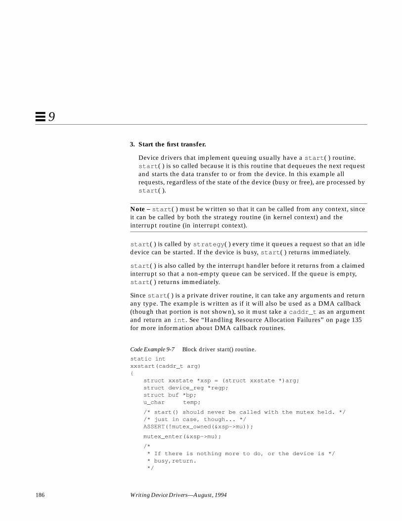
186 Writing Device Drivers—August, 1994
9
3. Start the first transfer.
Device drivers that implement queuing usually have a start ( ) routine.start ( ) is so called because it is this routine that dequeues the next requestand starts the data transfer to or from the device. In this example allrequests, regardless of the state of the device (busy or free), are processed bystart ( ).
Note – start ( ) must be written so that it can be called from any context, sinceit can be called by both the strategy routine (in kernel context) and theinterrupt routine (in interrupt context).
start ( ) is called by strategy ( ) every time it queues a request so that an idledevice can be started. If the device is busy, start ( ) returns immediately.
start ( ) is also called by the interrupt handler before it returns from a claimedinterrupt so that a non-empty queue can be serviced. If the queue is empty,start ( ) returns immediately.
Since start ( ) is a private driver routine, it can take any arguments and returnany type. The example is written as if it will also be used as a DMA callback(though that portion is not shown), so it must take a caddr_t as an argumentand return an int . See “Handling Resource Allocation Failures” on page 135for more information about DMA callback routines.
Code Example 9-7 Block driver start() routine.
static intxxstart(caddr_t arg){
struct xxstate *xsp = (struct xxstate *)arg;struct device_reg *regp;struct buf *bp;u_char temp;
/* start() should never be called with the mutex held. *//* just in case, though... */ASSERT(!mutex_owned(&xsp->mu));
mutex_enter(&xsp->mu);
/* * If there is nothing more to do, or the device is */ * busy,return. */

Drivers for Block Devices 187
9
if (xsp->list_head == NULL || xsp->busy) {mutex_exit(&xsp->mu);return (0);
}xsp->busy = 1;
/* Get the first buffer off the transfer list */bp = xsp->list_head;
/* Update the head and tail pointer */xsp->list_head = xsp->list_head->av_forw;if (xsp->list_head == NULL)
xsp->list_tail = NULL;bp->av_forw = NULL;
mutex_exit(&xsp->mu);
set up DMA resources with ddi_dma_buf_setup(9F)
xsp->bp = bp;
/* Set up device DMA engine from the cookie. */regp = xsp->regp;regp->dma_addr = cookie.dmac_address;regp->dma_size = cookie.dmac_size;regp->csr = ENABLE_INTERRUPTS | START_TRANSFER;
/* Read the csr to flush any hardware store buffers */temp = regp->csr;
return (0);}
4. Handle the interrupting Device
The interrupt routine is very similar to the asynchronous version, with theaddition of the call to start () and the removal of the call tocv_signal (9F).
Code Example 9-8 Asynchronous block driver interrupt routine.
static u_intxxintr(caddr_t arg){
struct xxstate *xsp = (struct xxstate *)arg;struct buf *bp;u_char temp, status;
mutex_enter(&xsp->mu);

188 Writing Device Drivers—August, 1994
9
status = xsp->regp->csr;if (!(status & INTERRUPTING)) {
mutex_exit(&xsp->mu);return (DDI_INTR_UNCLAIMED);
}
/* Get the buf responsible for this interrupt */bp = xsp->bp;xsp->bp = NULL;
/* * This example is for a simple device which either * succeeds or fails the data transfer, indicated in the * command/status register. */if (status & DEVICE_ERROR) {
/* failure */bp->b_resid = bp->b_bcount;bioerror(bp, EIO);
} else {/* success */bp->b_resid = 0;
}
xsp->regp->csr = CLEAR_INTERRUPT;/* Read the csr to flush any hardware store buffers */temp = xsp->regp->csr;
/* The transfer has finished, successfully or not */biodone(bp);
release any resources used in the transfer, such as DMA resources (ddi_dma_free(9F))
/* Let the next I/O thread have access to the device */xsp->busy = 0;mutex_exit(&xsp->mu);
(void) xxstart((caddr_t xsp);
return (DDI_INTR_CLAIMED);}
Miscellaneous Entry Points
dump( )
The dump(9E) entry point is used to dump a portion of virtual address spacedirectly to the specified device in the case of a system failure.

Drivers for Block Devices 189
9
int xxdump(dev_t dev, caddr_t addr,daddr_t blkno,int nblk)
dev is the device number of the device to dump to, addr is the base kernelvirtual address to start the dump at, blkno is the beginning block to dump to,and nblk is the number of blocks to dump. The example depends on theexisting driver working properly. It creates a buf (9S) request to pass tostrategy (9E). Interrupts are not necessarily enabled at this point, soxxdump() calls a special version of strategy (9E) (not shown) that only doespolled I/O (non-interrupt driven).
Code Example 9-9 Block driver dump(9E) routine.
static intxxdump(dev_t dev, caddr_t addr, daddr_t blkno, int nblk){
int error;struct buf *bp;
/* Allocate a buf structure to perform the dump */bp = getrbuf(KM_NOSLEEP);if (bp == NULL)
return (EIO);
/* * Set the appropriate fields in the buf structure. * This is OK since the driver knows what its strategy * routine will examine. */bp->b_un.b_addr = addr;bp->b_edev = dev;bp->b_bcount = nblk * DEV_BSIZE;bp->b_flags = B_WRITE|B_KERNBUF;bp->b_blkno = blkno;
disable interrupts
(void) xxstrategy_poll(bp);
/* * Wait here until the driver performs a biodone(9F) * on the buffer being transferred. */error = biowait(bp);freerbuf(bp);return (error);
}

190 Writing Device Drivers—August, 1994
9
print( )
int xxprint(dev_t dev, char *str)
The print (9E) entry is called by the system to display a message about anexception it has detected. print (9E) should call cmn_err (9F) to post themessage to the console on behalf of the system. Here is an example:
static intxxprint(dev_t dev, char *str){
cmn_err(CE_CONT, “xx: %s\n”, str);return (0);
}

191
SCSI Target Drivers 10
This chapter describes how to write a SCSI target driver using the interfacesprovided by the Sun Common SCSI Architecture (SCSA). Overviews of SCSIand SCSA are presented, followed by the details of implementing a targetdriver.
Note – Target driver developers may be interested in SCSI HBA driverinformation. A SCSI HBA chapter in progress (SCSIHBA.PS) is included as a.ps file in the DDK. It is located in this path: opt/SUNWddk/doc
OverviewThe Solaris 2.4 DDI/DKI divides the software interface to SCSI devices intotwo major parts: target drivers and host bus adapter (HBA) drivers. Target refersto a driver for a device on a SCSI bus, such as a disk or a tape drive. host busadapter refers to the driver for the SCSI controller on the host machine, such asthe “esp” driver on a SPARCstation. SCSA defines the interface between thesetwo components. This chapter discusses target drivers only. See SCSI HBADrivers for information on host bus adapter drivers.
Note – The terms “host bus adapter” or “HBA” used in this manual areequivalent to the phrase “host adapter” as defined in SCSI specifications.

192 Writing Device Drivers—August, 1994
10
Target drivers can be either character or block device drivers, depending on thedevice. Drivers for tape drives are usually character device drivers, while disksare handled by block device drivers. This chapter describes how to write aSCSI target driver and discusses the additional requirements that SCSA placeson block and character drivers for SCSI target devices.
Reference DocumentsThe following reference documents provide supplemental information neededby the designers of target drivers and host bus adapter drivers.
Small Computer System Interface (SCSI) Standard, ANSI X3.131-1986 AmericanNational Standards InstituteSales Department1430 Broadway, New York, NY 10018Phone (212) 642-4900)
Small Computer System Interface 2 (SCSI-2) Standard, document X3.131-1994Global Engineering Documents15 Inverness Way, East Englewood, CO 80112-5704Phone: 800-854-7179 or 303-792-2181FAX: 303-792-2192
Basics of SCSIANCOT CorporationMenlo Park, California 94025Phone (415) 322-5322FAX: (415) 322-0455
Also, refer to the SCSI command specification for the target device, providedby the hardware vendor.
For information on setting global SCSI options see Appendix B, “AdvancedTopics.”
For a pointer to SCSI driver sample code see Appendix D, “Sample DriverSource Code Listings”.

SCSI Target Drivers 193
10
Sun Common SCSI Architecture OverviewThe Sun Common SCSI Architecture (SCSA) is the Solaris 2.4 DDI/DKIprogramming interface for the transmission of SCSI commands from a targetdriver to a host bus adapter driver. This interface is independent of the type ofhost bus adapter hardware, the platform, the processor architecture, and theSCSI command that is being transported across the interface.
By conforming to the SCSA, the target driver can pass any SCSI command to atarget device without knowledge of the hardware implementation of the hostbus adapter.
The SCSA conceptually separates building the SCSI command (by the targetdriver) from transporting the SCSI command and data across the SCSI bus.
The architecture defines the software interface between high-level and low-level software components. The higher level software component consists ofone or more SCSI target drivers, which translate I/O requests into SCSIcommands appropriate for the peripheral device.
Figure 10-1 SCSA Block Diagram
Application Program 1 Application Program 2
System Calls
Sun Common SCSI Architecture (SCSA)
Target
Host Bus AdapterDriver 1
SCSI HardwareInterface
Driver 1Target
Driver 2Target
Driver 3
Host Bus AdapterDriver 2
SCSI HardwareInterface
Kernel
Applications
Hardware

194 Writing Device Drivers—August, 1994
10
The lower-level software component consists of a SCSA interface layer and oneor more host bus adapter drivers. The host bus adapter driver has severalresponsibilities. It must:
• Manage host bus adapter hardware• Accept SCSI commands from the SCSI target driver• Transport the commands to the specified SCSI target device• Perform any data transfers that the command requires• Collect status• Handle auto-request sense (optional)• Inform the target driver of command completion (or failure)
The target driver is completely responsible for the generation of the properSCSI commands required to execute the desired function.
General Flow of Control
When transferring data to or from a user address space (using the read (9E) orwrite (9E) entry points) SCSI target character device drivers must usephysio (9F) to encode the request into a buf (9S) structure and call the driver’sstrategy (9E) routine.
physio (9F) locks down the user buffer into memory before issuing a SCSIcommand. The file system locks down memory for block device drivers. SeeChapter 9, “Drivers for Block Devices”, for more information on writing astrategy (9E) entry point and Chapter 8, “Drivers for Character Devices”, formore information on using physio (9F).
Assuming no transport errors occur, the following steps describe the generalflow of control for a read or write request starting from the call to the targetdriver’s strategy routine:
1. The target driver’s strategy (9E) routine checks the request and allocates ascsi_pkt (9S) using scsi_init_pkt (9F). The target driver initializes thepacket and sets the SCSI CDB using the makecom (9F) function. The targetdriver also specifies a timeout and provides a pointer to a callback function,which is called by the host bus adapter driver on completion of thecommand. The buf (9S) pointer should be saved in the scsi packet’s target-private space.
SCSI Target Drivers 195
10
2. The target driver submits the packet to the host bus adapter driver usingscsi_transport (9F). The target driver is then free to accept otherrequests. The target driver should not access the packet while it is intransport. If either the host bus adapter driver or the target supportqueueing, new requests can be submitted while the packet is in transport.
3. As soon as the SCSI bus is free and the target not busy, the host bus adapterdriver selects the target and passes the CDB. The target executes thecommand and performs the requested data transfers. The target controls theSCSI bus phase transitions. The host bus adapter just responds to thesetransitions until the command completes.
4. After the target sends completion status and disconnects, the host busadapter driver notifies the target driver by calling the completion functionwhich was specified in the scsi packet. At this time the host bus adapterdriver is no longer responsible for the packet, and the target driver hasregained ownership of the packet.
5. The SCSI packet’s completion routine analyzes the returned information anddetermines whether the SCSI operation was successful. If a failure hasoccurred, the target driver may retry the command by callingscsi_transport (9F) again. If the host bus adapter driver does not supportauto request sense, the target driver must submit a request sense packet inorder to retrieve the sense data in the event of a check condition.
6. If either the command completed successfully or cannot be retried, thetarget driver calls scsi_destroy_pkt (9F) which synchronizes the dataand frees the packet. If the target driver needs to access the data beforefreeing the packet, it may call scsi_sync_pkt (9F)
7. Finally, the target driver notifies the application program that originallyrequested the read or write that the transaction is complete, either byreturning from the read (9E) entry point in the driver (for a characterdevice), or indirectly through biodone (9F).
The SCSA allows the execution of many of such operations, both overlappedand queued at various points in the process. The model places themanagement of system resources on the host bus adapter driver. The softwareinterface allows the execution of target driver functions on host bus adapterdrivers using SCSI bus adapters of varying degrees of intelligence.
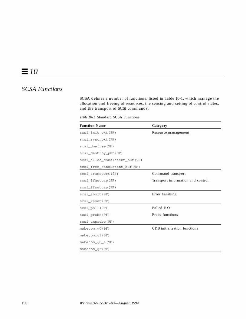
196 Writing Device Drivers—August, 1994
10
SCSA FunctionsSCSA defines a number of functions, listed in Table 10-1, which manage theallocation and freeing of resources, the sensing and setting of control states,and the transport of SCSI commands:
Table 10-1 Standard SCSA Functions
Function Name Category
scsi_init_pkt(9F) Resource management
scsi_sync_pkt(9F)
scsi_dmafree(9F)
scsi_destroy_pkt(9F)
scsi_alloc_consistent_buf(9F)
scsi_free_consistent_buf(9F)
scsi_transport(9F) Command transport
scsi_ifgetcap(9F) Transport information and control
scsi_ifsetcap(9F)
scsi_abort(9F) Error handling
scsi_reset(9F)
scsi_poll(9F) Polled I/O
scsi_probe(9F) Probe functions
scsi_unprobe(9F)
makecom_g0(9F) CDB initialization functions
makecom_g1(9F)
makecom_g0_s(9F)
makecom_g5(9F)

SCSI Target Drivers 197
10
SCSA Compatibility FunctionsThe functions listed in Table 10-2 are maintained for both source and binarycompatibility with previous releases. However, new drivers should use thenew functions listed in Table 10-1.
SCSI Target Drivers
Hardware Configuration File
Since SCSI devices are not self-identifying, a hardware configuration file isrequired for a target driver (see driver.conf (4) and scsi (4) for details). Atypical configuration file looks like this:
name=”xx” class=”scsi” target=2 lun=0;
The system reads the file during autoconfiguration and uses the class propertyto identify the driver’s possible parent. The system then attempts to attach thedriver to any parent driver that is of class “scsi”. All host bus adapter driversare of this class. Using the class property rather than the parent property allowsthe target driver to be attached to any host bus adapter driver that finds theexpected device at the specified target and lun ids. The target driver isresponsible for verifying this in its probe (9E) routine.
Table 10-2 SCSA Compatibility Functions
Function Name Category
scsi_resalloc(9F) Resource management
scsi_resfree(9F)
scsi_pktalloc(9F)
scsi_pktfree(9F)
scsi_dmaget(9F)
get_pktiopb(9F)
free_pktiopb(9F)
scsi_slave(9F) Probe functions
scsi_unslave(9F)
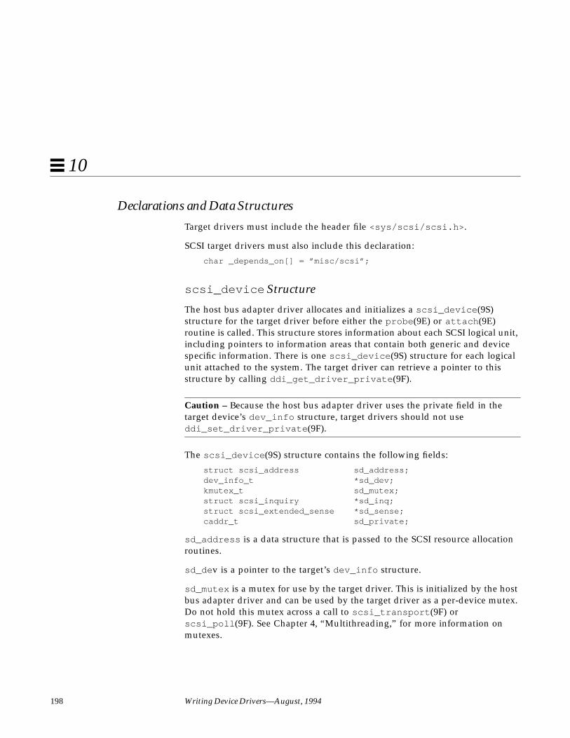
198 Writing Device Drivers—August, 1994
10
Declarations and Data Structures
Target drivers must include the header file <sys/scsi/scsi.h> .
SCSI target drivers must also include this declaration:
char _depends_on[] = ”misc/scsi”;
scsi_device Structure
The host bus adapter driver allocates and initializes a scsi_device (9S)structure for the target driver before either the probe (9E) or attach (9E)routine is called. This structure stores information about each SCSI logical unit,including pointers to information areas that contain both generic and devicespecific information. There is one scsi_device (9S) structure for each logicalunit attached to the system. The target driver can retrieve a pointer to thisstructure by calling ddi_get_driver_private (9F).
Caution – Because the host bus adapter driver uses the private field in thetarget device’s dev_info structure, target drivers should not useddi_set_driver_private (9F).
The scsi_device (9S) structure contains the following fields:
struct scsi_address sd_address;dev_info_t *sd_dev;kmutex_t sd_mutex;struct scsi_inquiry *sd_inq;struct scsi_extended_sense *sd_sense;caddr_t sd_private;
sd_address is a data structure that is passed to the SCSI resource allocationroutines.
sd_de v is a pointer to the target’s dev_info structure.
sd_mutex is a mutex for use by the target driver. This is initialized by the hostbus adapter driver and can be used by the target driver as a per-device mutex.Do not hold this mutex across a call to scsi_transport (9F) orscsi_poll (9F). See Chapter 4, “Multithreading,” for more information onmutexes.

SCSI Target Drivers 199
10
sd_inq is a pointer for the target device’s SCSI Inquiry data. Thescsi_probe (9F) routine allocates a buffer, fills it in, and attaches it to thisfield.
sd_sense is a pointer to a buffer to contain SCSI Request Sense data from thedevice. The target driver must allocate and manage this buffer itself; see“attach( )” on page 202.
sd_private is a pointer field for use by the target driver. It is commonly usedto store a pointer to a private target driver state structure.
scsi_pkt Structure
This structure contains the following fields:
struct scsi_address pkt_address;opaque_t pkt_private;void (*pkt_comp)(struct scsi_pkt *pkt);long pkt_flags;u_long pkt_time;u_char *pkt_scbp;u_char *pkt_cdbp;long pkt_resid;u_long pkt_state;u_long pkt_statistics;u_char pkt_reason;
pkt_address is the target device’s address set by scsi_init_pkt (9F)
pkt_private is a place to store private data for the target driver. It iscommonly used to save the buf (9S) pointer for the command.
pkt_comp is the address of the completion routine. The host bus adapterdriver calls this routine when it has transported the command. This does notmean that the command succeeded; the target might have been busy or maynot have responded before the time-out time elapsed (see the description forpkt_time field). The target driver must supply a valid value in this field,though it can be NULL if the driver does not want to be notified.

200 Writing Device Drivers—August, 1994
10
Note – There are two different SCSI callback routines. The pkt_comp fieldidentifies a completion callback routine, called when the host bus adaptercompletes its processing. There is also a resource callback routine, called whencurrently unavailable resources are likely to be available (as inscsi_init_pkt (9F)).
pkt_flags provides additional control information, for example, to transportthe command without disconnect privileges (FLAG_NODISCON) or to disableparity (FLAG_NOPARITY). See scsi_pkt (9S) for details.
pkt_time is a timeout value (in seconds). If the command does not completewithin this time, the host bus adapter calls the completion routine withpkt_reason set to CMD_TIMEOUT. The target driver should set this field tolonger than the maximum time the command might take. If the timeout is zero,no timeout is requested. Timeout starts when the command is transmitted onthe SCSI bus.
pkt_scbp is a pointer to the SCSI Status completion block; this is filled in bythe host bus adapter driver.
pkt_cdbp is a pointer to the SCSI Command Descriptor Block, the actualcommand to be sent to the target device. The host bus adapter driver does notinterpret this field. The target driver must fill it in with a command that thetarget device understands.
pkt_resid is the residual of the operation. When allocating DMA resourcesfor a command (scsi_init_pkt (9F), pkt_resid indicates the number ofbytes for which DMA resources could not be allocated due to DMA hardwarescatter/gather or other device limitations. After command transport,pkt_resid indicates the number of data bytes not transferred; this is filled inby the host bus adapter driver before the completion routine is called.
pkt_state indicates the state of the command. The host bus adapter driverfills in this field as the command progresses. One bit is set in this field for eachof the five following command states:
• STATE_GOT_BUS - Acquired the bus• STATE_GOT_TARGET - Selected the target• STATE_SENT_CMD - Sent the command• STATE_XFERRED_DATA - Transferred data (if appropriate)• STATE_GOT_STATUS - Received status from the device
SCSI Target Drivers 201
10
pkt_statistics contains transport-related statistics, set by the host busadapter driver.
pkt_reason gives the reason the completion routine was called. The mainfunction of the completion routine is to decode this field and take theappropriate action. If the command completed—in other words, if there wereno transport errors—this field is set to CMD_CMPLT; other values in this fieldindicate an error. After a command completes, the target driver shouldexamine the pkt_scbp field for a check condition status. See scsi_pkt (9S)for more information.
State Structure
This section adds the following fields to the state structure. See “StateStructure” on page 57 for more information.
struct scsi_pkt *rqs; /* Request Sense packet */struct buf *rqsbuf; /* buf for Request Sense */struct scsi_pkt *pkt; /* packet for current command */struct scsi_device *sdp; /* pointer to device’s */
/* scsi_device(9S) structure. */
rqs is a pointer to a SCSI Request Sense command scsi_pkt (9S) structure,allocated in the attach (9E) routine. This packet is preallocated because theRequest Sense command is small and may be used in time-critical areas of thedriver (such as when handling errors).
Autoconfiguration
SCSI target drivers must implement the standard autoconfiguration routines_init (9E), _fini (9E), _info (9E), and identify (9E). See Chapter 5,“Autoconfiguration,” for more information.
probe (9E), attach (9E), and getinfo (9E) are also required, but they mustperform SCSI (and SCSA) specific processing.
probe( )
SCSI target devices are not self-identifying, so target drivers must have aprobe (9E) routine. This routine must determine whether or not the expectedtype of device is present and responding.

202 Writing Device Drivers—August, 1994
10
The general structure and return codes of the probe (9E) routine are the sameas those of other device drivers. See probe () on page 87 for more information.SCSI target drivers must use the scsi_probe (9F) routine in their probe (9E)entry point. scsi_probe (9F) sends a SCSI Inquiry command to the device andreturns a code indicating the result. If the SCSI Inquiry command is successful,scsi_probe (9F) allocates a scsi_inquiry (9S) structure and fills it in withthe device’s Inquiry data. Upon return from scsi_probe (9F), the sd_inqfield of the scsi_device (9S) structure points to this scsi_inquiry (9S)structure.
Since probe (9E) must be stateless, the target driver must callscsi_unprobe (9F) before probe (9E) returns, even if scsi_probe (9F) fails.
Code Example 10-1 shows a typical probe (9E) routine. It uses theddi_getprop (9F) routine to retrieve the device’s SCSI target and logical unitnumbers so that it can print them in messages. It also retrieves itsscsi_device (9S) structure from the private field of its dev_info structure.The probe (9E) routine then calls scsi_probe (9F) to verify that the expecteddevice (a printer in this case) is present.
If scsi_probe (9F) succeeds, it has attached the device’s SCSI Inquiry data ina scsi_inquiry (9S) structure, to the sd_inq field of the scsi_device (9S)structure. The driver can then check to see if the device type is a printer(reported in the inq_dtype field). If it is, the type is reported withscsi_log (9F), using scsi_dname (9F) to convert the device type into a string.
Code Example 10-1 SCSI target driver probe (9E) routine
static intxxprobe(dev_info_t *dip){
struct scsi_device *sdp;int rval, target, lun;
/* * Get the SCSI target/lun properties. DDI_PROP_DONTPASS * prevents ddi_getprop from looking beyond this node for the * properties. */target = ddi_getprop(DDI_DEV_T_ANY, dip, DDI_PROP_DONTPASS,
“target”, -1);lun = ddi_getprop(DDI_DEV_T_ANY, dip, DDI_PROP_DONTPASS,
SCSI Target Drivers 203
10
“lun”, -1);if ((target == -1) || (lun == -1))
return (DDI_FAILURE);
/* * Get a pointer to the scsi_device(9S) structure */sdp = (struct scsi_device *) ddi_get_driver_private(dip);
/* * Call scsi_probe(9F) to send the Inquiry command. It will * fill in the sd_inq field of the scsi_device structure. */switch (scsi_probe(sdp, NULL_FUNC)) {case SCSIPROBE_FAILURE:case SCSIPROBE_NORESP:case SCSIPROBE_NOMEM:
/* * In these cases, device may be powered off, * in which case we may be able to successfully * probe it at some future time - referred to * as ‘deferred attach’. */rval = DDI_PROBE_PARTIAL;break;
case SCSIPROBE_NONCCS:default:
/* * Device isn’t of the type we can deal with, * and/or it will never be useable. */rval = DDI_PROBE_FAILURE;break;
case SCSIPROBE_EXISTS:/* * There is a device at the target/lun address. Check * inq_dtype to make sure that it is the right device * type. See scsi_inquiry(9S)for possible device types. */switch (sdp->sd_inq->inq_dtype) {case DTYPE_PRINTER:
scsi_log(sdp, “xx”, SCSI_DEBUG,“found %s device at target%d, lun%d\n”,scsi_dname((int)sdp->sd_inq->inq_dtype),target, lun);
rval = DDI_PROBE_SUCCESS;break;

204 Writing Device Drivers—August, 1994
10
case DTYPE_NOTPRESENT:default:
rval = DDI_PROBE_FAILURE;break;
}}
scsi_unprobe(sdp);return (rval);
}
A more thorough probe (9E) routine could also check other fields of thescsi_inquiry (9S) structure as necessary to make sure that the device is ofthe type expected by a particular driver.
attach( )
After the probe (9E) routine has verified that the expected device is present,attach (9E) is called. This routine allocates and initializes any per-instancedata and creates minor device node information. See “attach( )” on page 95 fordetails of this. In addition to these steps, a SCSI target driver again callsscsi_probe (9F) to retrieve the device’s Inquiry data and also creates a SCSIRequest Sense packet. If the attach is successful, the attach function should notcall scsi_unprobe .
Three routines are used to create the Request Sense packet:scsi_alloc_consistent_buf (9F), scsi_init_pkt (9F), andmakecom_g0(9F). scsi_alloc_consistent_buf (9F) allocates a buffersuitable for consistent DMA and returns a pointer to a buf (9S) structure. Theadvantage of a consistent buffer is that no explicit syncing of the data isrequired. In other words, the target driver can access the data after thecallback. The sd_sense element of the device’s scsi_device (9S) structuremust be initialized with the address of the sense buffer. scsi_init_pkt (9F)creates and partially initializes a scsi_pkt (9S) structure. makecom_g0(9F)creates a SCSI Command Descriptor Block (CDB), in this case creating a SCSIRequest Sense command.
Code Example 10-2 SCSI target driver attach (9E) routine.
static intxxattach(dev_info_t *dip, ddi_attach_cmd_t cmd){
struct xxstate *xsp;
SCSI Target Drivers 205
10
struct scsi_pkt *rqpkt = NULL;struct scsi_device *sdp;struct buf *bp = NULL;int instance;
instance = ddi_get_instance(dip);
allocate a state structure and initialize it
...xsp = ddi_get_soft_state(statep, instance);sdp = (struct scsi_device *) ddi_get_driver_private(dip);
/* * Cross-link the state and scsi_device(9S) structures. */sdp->sd_private = (caddr_t) xsp;xsp->sdp = sdp;
call scsi_probe(9F) again to get and validate inquiry data
/* * Allocate a request sense buffer. The buf(9S) structure * is set to NULL to tell the routine to allocate a new * one. The callback function is set to NULL_FUNC to tell * the routine to return failure immediately if no * resources are available. */bp = scsi_alloc_consistent_buf(&sdp->sd_address, NULL,
SENSE_LENGTH, B_READ, NULL_FUNC, NULL);if (bp == NULL)
goto failed;
/* * Create a Request Sense scsi_pkt(9S) structure. */rqpkt = scsi_init_pkt(&sdp->sd_address, NULL, bp,
CDB_GROUP0, 1, 0, PKT_CONSISTENT, NULL_FUNC, NULL);if (rqpkt == NULL)
goto failed;
/* * scsi_alloc_consistent_buf(9F) returned a buf(9S) structure. * The actual buffer address is in b_un.b_addr. */sdp->sd_sense = (struct scsi_extended_sense *) bp->b_un.b_addr;
206 Writing Device Drivers—August, 1994
10
/* * Create a Group0 CDB for the Request Sense command */makecom_g0(rqpkt, devp, FLAG_NOPARITY, SCMD_REQUEST_SENSE,
0, SENSE_LENGTH);
/* * Fill in the rest of the scsi_pkt structure. * xxcallback() is the private command completion routine. */rqpkt->pkt_comp = xxcallback;rqpkt->pkt_time = 30; /* 30 second command timeout */rqpkt->pkt_flags |= FLAG_SENSING;xsp->rqs = rqpkt;xsp->rqsbuf = bp;
create minor nodes, report device, and do any other initialization
xsp->open = 0;return (DDI_SUCCESS);
failed:if (bp)
scsi_free_consistent_buf(bp);if (rqpkt)
scsi_destroy_pkt(rqpkt);
sdp->sd_private = (caddr_t) NULL;sdp->sd_sense = NULL;scsi_unprobe(sdp);
free any other resources, such as the state structure
return (DDI_FAILURE);}
detach( )
The detach (9E) entry point is the inverse of attach (9E); it must free allresources that were allocated in attach (9E). If successful, the detach shouldcall scsi_unprobe .
Code Example 10-3 SCSI target driver detach (9E) routine
static intxxdetach(dev_info_t *dip, ddi_detach_cmd_t cmd){
struct xxstate *xsp;

SCSI Target Drivers 207
10
normal detach(9E) operations, such as getting a pointer to the state structure
...scsi_free_consistent_buf(xsp->rqsbuf);scsi_destroy_pkt(xsp->rqs);
xsp->sdp->sd_private = (caddr_t) NULL;xsp->sdp->sd_sense = NULL;scsi_unprobe(xsp->sdp);
remove minor nodesfree resources, such as the state structure
return (DDI_SUCCESS);}
getinfo ( )
The getinfo (9E) routine for SCSI target drivers is much the same as for otherdrivers; see “getinfo( )” on page 102 for more information onDDI_INFO_DEVT2INSTANCE case. However, in theDDI_INFO_DEVT2DEVINFO case of the getinfo (9E) routine, the target drivermust return a pointer to its dev_info node. This can be saved in the driverstate structure or can be retrieved from the sd_dev field of thescsi_device (9S) structure.
Code Example 10-4 Alternative SCSI target driver getinfo (9E) code fragment
...case DDI_INFO_DEVT2DEVINFO:
dev = (dev_t) arg;instance = getminor(dev);xsp = ddi_get_soft_state(statep, instance);if (xsp == NULL)
return (DDI_FAILURE);*result = (void *) xsp->sdp->sd_dev;return (DDI_SUCCESS);
...
Resource Allocation
To send a SCSI command to the device, the target driver must create andinitialize a scsi_pkt (9S) structure and pass it to the host bus adapter driver.
208 Writing Device Drivers—August, 1994
10
scsi_init_pkt( )
The scsi_init_pkt (9F) routine allocates and zeros a scsi_pkt (9S)structure; it also sets pointers to pkt_private, *pkt_scbp, *pkt_cdbp .Additionally, it provides a callback mechanism to handle the case whereresources are not available. This structure contains the following fields:
struct scsi_pkt *scsi_init_pkt(struct scsi_address *ap,struct scsi_pkt *pktp, struct buf *bp, int cmdlen,int statuslen, int privatelen, int flags,int (*callback)(caddr_t), caddr_t arg)
ap is a pointer to a scsi_address structure. This is the sd_address field ofthe device’s scsi_device (9S) structure.
pktp is a pointer to the scsi_pkt (9S) structure to be initialized. If this is set toNULL, a new packet is allocated.
bp is a pointer to a buf (9S) structure. If this is non-NULL and contains a validbyte count, DMA resources are allocated.
cmdlen is the length of the SCSI Command Descriptor Block (CDB) in bytes.
statuslen is the required length of the SCSI status completion block, inbytes.
privatelen is the number of bytes to allocate for the pkt_private field. Tostore a pointer, specify the size of the pointer here (such as sizeof(structxxstate *) when storing a pointer to the state structure).
flags is a set of flags. Possible bits include:• PKT_CONSISTENT
This must be set if the DMA buffer was allocated usingscsi_alloc_consistent_buf (9F). In this case, the host bus adapterdriver guarantees that the data transfer is properly synchronized beforeperforming the target driver’s command completion callback.
• PKT_DMA_PARTIAL
This may be set if the driver can accept a partial DMA mapping. If set,scsi_init_pkt (9F) allocates DMA resources with theDDI_DMA_PARTIAL dmar_flag set. The pkt_resid (9E) field of thescsi_pkt (9S) structure may be returned with a non-zero residual,indicating the number of bytes for which scsi_init_pkt () was unableto allocate DMA resources.
SCSI Target Drivers 209
10
callback specifies the action to take if resources are not available. If set toNULL_FUNC, scsi_init_pkt (9F) returns immediately (returning NULL). If setto SLEEP_FUNC, it does not return until resources are available. Any othervalid kernel address is interpreted as the address of a function to be calledwhen resources are likely to be available.
arg is the parameter to pass to the callback function.
The scsi_sync_pkt (9F) routine can be used to synchronize any cached dataafter a transfer, when a target driver wants to reuse a scsi_pkt for anothercommand. This may be done either in the command completion routine orbefore calling scsi_transport (9F) for the command a second time.
The scsi_destroy_pkt (9F) routine synchronizes any remaining cached dataassociated with the packet, if necessary, and then frees the packet andassociated command, status, and target driver private data areas. This routineshould be called in the command completion routine (see scsi_pkt structureon page 193).
scsi_alloc_consistent_buf( )
For most I/O requests, the data buffer passed to the driver entry points is notaccessed directly by the driver, it is just passed on to scsi_init_pkt (9F). If adriver sends SCSI commands which operate on buffers the driver examinesitself (such as the SCSI Request Sense command), the buffers should be DMAconsistent. The scsi_alloc_consistent_buf (9F) routine allocates abuf (9S) structure and a data buffer suitable for DMA consistent operations.The HBA will perform any necessary synchronization of the buffer beforeperforming the command completion callback.
Caution – scsi_alloc_consistent_buf (9F) uses scarce system resources; itshould be used sparingly.
scsi_free_consistent_buf (9F) releases a buf (9S) structure and theassociated data buffer allocated with scsi_alloc_consistent_buf (9F). See“attach( )” on page 202 and “detach( )” on page 204 for examples.

210 Writing Device Drivers—August, 1994
10
Building and Transporting a CommandThe host bus adapter driver is responsible for transmitting the command to thedevice and taking care of the low-level SCSI protocol. Thescsi_transport (9F) routine hands a packet to the host bus adapter driverfor transmission. It is the target driver’s responsibility to create a validscsi_pkt (9S) structure.
Building a Command
The routine scsi_init_pkt (9F) allocates space for a SCSI CDB, allocatesDMA resources if necessary, and sets the pkt_flags field:
pkt = scsi_init_pkt(&sdp->sd_address, NULL, bp,CDB_GROUP0, 1, 0, 0, SLEEP_FUNC, NULL);
This example creates a new packet and allocates DMA resources as specified inthe passed buf (9S) structure pointer. A SCSI CDB is allocated for a Group 0 (6byte) command, the pkt_flags field is set to zero, but no space is allocatedfor the pkt_private field. This call to scsi_init_pkt (9F), because of theSLEEP_FUNC parameter, waits indefinitely for resources if none are currentlyavailable.
The next step is to initialize the SCSI CDB, using the makecom(9F) family offunctions:
makecom_g0(pkt, sdp, flags, SCMD_READ, bp->b_blkno, bp->b_bcount >> DEV_BSHIFT);
This example builds a Group 0 Command Descriptor Block and fills in thepkt_cdbp field as follows:
• The command itself (byte 0) is set from the fourth parameter (SCMD_READ).• The target device’s logical unit number (bits 5-7 of byte 1) is set using
sd_address field of sdp .• The pkt_flags field is set from the flags parameter.• The address field (bits 0-4 of byte 1 and bytes 2 and 3) is set from
bp->b_blkno .• The count field (byte 4) is set from the last parameter. In this case it is set to
bp->b_bcount >> DEV_BSHIFT , where DEV_BSHIFT is the byte count ofthe transfer converted to the number of blocks.
After initializing the SCSI CDB, initialize three other fields in the packet andstore as a pointer to the packet in the state structure.
SCSI Target Drivers 211
10
pkt->pkt_private = (opaque_t) bp;pkt->pkt_comp = xxcallback;pkt->pkt_time = 30;xsp->pkt = pkt;
The buf (9S) pointer is saved in the pkt_private field for later use in thecompletion routine.
Transporting a Command
After creating and filling in the scsi_pkt (9S) structure, the final step is tohand it to the host bus adapter driver:
if (scsi_transport(pkt) != TRAN_ACCEPT) {bp->b_resid = bp->b_bcount;bioerror(bp, EIO);biodone(bp);
}
The other return values from scsi_transport (9F) are:
• TRAN_BUSY - There is already a command in progress for the specifiedtarget.
• TRAN_BADPKT - The DMA count in the packet was too large.
• TRAN_BADPKT - The host adapter driver rejected this packet.
• TRAN_FATAL_ERROR- The host adapter driver is unable to accept thispacket.
Warning – The mutex sd_mutex in the scsi_device (9S) structure must notbe held across a call to scsi_transport (9F).
If scsi_transport (9F) returns TRAN_ACCEPT, the packet is the responsibilityof the host bus adapter driver and should not be accessed by the target driveruntil the command completion routine is called.

212 Writing Device Drivers—August, 1994
10
Command Completion
Once the host bus adapter driver has done all it can with the command, itinvokes the packet’s completion callback routine, passing a pointer to thescsi_pkt (9S) structure as a parameter. The completion routine decodes thepacket and takes the appropriate action. A simple completion routine is givenin Code Example 10-5.
Code Example 10-5 SCSI driver completion routine
static voidxxcallback(struct scsi_pkt *pkt){
struct buf *bp;struct xxstate *xsp;int instance;struct scsi_status *ssp;
/* * Get a pointer to the buf(9S) structure for the command * and to the per-instance data structure. */bp = (struct buf *) pkt->pkt_private;instance = getminor(bp->b_edev);xsp = ddi_get_soft_state(statep, instance);
/* * Figure out why this callback routine was called */if (pkt->pkt_reason != CMP_CMPLT) {
bp->b_resid = bp->b_bcount;bioerror(bp, EIO);scsi_destroy_pkt(pkt); /* release resources */biodone(bp); /* notify waiting threads */ ;
} else {/* * Command completed, check status. * See scsi_status(9S) */ssp = (struct scsi_status *) pkt->pkt_scbp;if (ssp->sts_busy) {
error, target busy or reserved} else if (ssp->sts_chk) {
send a request sense command} else {
bp->b_resid = pkt->pkt_resid; /*packet completed OK */
SCSI Target Drivers 213
10
scsi_destroy_pkt(pkt);biodone(bp);
}}
}
This is a very simple completion callback routine. It checks to see whether thecommand completed and if it did not, gives up immediately. If the target wasbusy it gives up, or if it returned a “check condition” status, it sends a RequestSense command.
Otherwise, the command succeeded. If this is the end of processing for thecommand, it destroys the packet and calls biodone (9F).
This example does not attempt to retry incomplete commands. SeeAppendix D, “Sample Driver Source Code Listings” for information aboutsample SCSI drivers. Also see Appendix B, “Advanced Topics” for furtherinformation.

214 Writing Device Drivers—August, 1994
10

215
Device Context Management 11
Some device drivers, such as those for graphics hardware, provide userprocesses with direct access to the device. These devices often require that onlyone process at a time accesses the device.
This chapter describes the set of interfaces that allow device drivers to manageaccess to such devices.
What Is A Device Context?The context of a device is the current state of the device hardware. The devicecontext for a process is managed by the device driver on behalf of the process.The device driver must maintain a separate device context for each processthat accesses the device. It is the device driver’s responsibility to restore thecorrect device context when a process accesses the device.
Context Management ModelAn accelerated frame buffer is an example of a device that allows userprocesses (such as graphics applications) to directly manipulate the controlregisters of the device through memory-mapped access. Since these processesare not using the traditional I/O system calls (read (2), write (2), andioctl (2)), the device driver is no longer called when a process accesses thedevice. However, it is important that the device driver be notified when aprocess is about to access a device so that it can restore the correct devicecontext and provide any needed synchronization.

216 Writing Solaris Graphics Device Drivers—August, 1994
11
To resolve this problem, the device context management interfaces allow adevice driver to be notified when a user processes accesses memory-mappedregions of the device and to control accesses to the device’s hardware.Synchronization and management of the various device contexts is theresponsibility of the device driver. When a user process accesses a mapping,the device driver must restore the correct device context for that process.
A device driver will be notified whenever one of the following events occurson a mapping:
• Access to a mapping by a user process
• Duplication of a mapping by a user process
• Freeing of a mapping by a user process
Figure 11-1 is a snapshot of multiple user processes that have memory mappeda device. Process B has been granted access to the device by the driver, and thedriver no longer requires notification by process B. However, the driver doesrequire notification if either process A or process C access the device.
Figure 11-1 Device context management
Process A Process B
Device
Current Context
User Processes
Hardware
Process C

Device Context Management 217
11
At some point in the future, process A accesses the device. The device driver isnotified of this and blocks future access to the device by process B. It thenrestores the device context of process A and grants access to process A. This isillustrated in Figure 11-2. At this point, the device driver requires notification ifeither process B or process C access the device.
Figure 11-2 Device context switched to user process A
Multiprocessor Considerations
On a multiprocessor machine, multiple processes could be attempting to accessthe device at the same time. This can cause thrashing. The kernel prevents thisfrom happening by guaranteeing that once a device driver has granted accessto a process, no other process will be allowed to request access to the samedevice for at least one clock tick.
However, some devices require more time to restore a device context thanothers. To prevent more CPU time from being used to restore a device contextthan to actually use that device context, the time that a process needs to haveaccess to the device must be increased. If more time than one click tick is
Device
Current Context
Process A Process B Process CUser
Hardware
Processes

218 Writing Solaris Graphics Device Drivers—August, 1994
11
required, the driver can block new access to the device for an additionalpredetermined amount of time using the standard thread synchronizationfunction calls. See “Thread Synchronization” on page 79 for more information.
Context Management OperationIn general, here are the steps for performing device context management:
1. Define a ddi_mapdev_ctl (9S) structure.
2. Allocate space to save device context if necessary.
3. Set up user mappings to the device and driver notifications withddi_mapdev (9F).
4. Manage user access to the device with ddi_mapdev_intercept (9F) andddi_mapdev_nointercept (9F).
5. Free the device context structure if needed.
State Structure
This section adds the following fields to the state structure. See “StateStructure” on page 51 for more information.
kmutex_t ctx_lock;struct xxctx *current_ctx;
The structure xxctx is the driver private device context structure for theexamples used in this section. It looks like this:
struct xxctx {ddi_mapdev_handle_t handle;char context[XXCTX_SIZE];struct xxstate *xsp;
};
The context field stores the actual device context. In this case, it is simply achunk of memory; in other cases, it may actually be a series of structure fieldscorresponding to device registers.

Device Context Management 219
11
Declarations and Data Structures
Device drivers that use the device context management interfaces must includethe following declaration:
char _depends_on[] = “misc/seg_mapdev” ;
ddi_mapdev_ctl ()
The device driver must allocate and initialize a ddi_mapdev_ctl (9S) structureto inform the system of its device context management entry point routines.
This structure contains the following fields:
struct ddi_mapdev_ctl {int mapdev_rev;int (*mapdev_access)(ddi_mapdev_handle_t handle,
void *private, off_t offset);void (*mapdev_free)(ddi_mapdev_handle_t handle, void
*private);int (*mapdev_dup)(ddi_mapdev_handle_t oldhandle,
void *oldprivate, ddi_mapdev_handle_t newhandle,void **newprivate);
};
mapdev_rev is the version number of the ddi_mapdev_ctl (9S) structure. Itmust be set to MAPDEV_REV.
mapdev_access must be set to the address of the driver’smapdev_access (9E) entry point.
mapdev_free must be set to the address of the driver’s mapdev_free (9E)entry point.
mapdev_dup must be set to the address of the driver’s mapdev_dup (9E) entrypoint.
Associating Devices with User Mappings
When a user process requests a mapping to a device with mmap(2), the device‘ssegmap(9E) entry point is called. The device must use ddi_mapdev (9F) whensetting up the memory mapping if it wants to manage device contexts.Otherwise the device driver must use ddi_segmap (9F) to set up the mapping.

220 Writing Solaris Graphics Device Drivers—August, 1994
11
Unlike, ddi_segmap (9E), ddi_mapdev (9F) can not be used directly as anentry point in the cb_ops (9S) structure. You must define a segmap(9E) entrypoint to use ddi_mapdev (9F).
int ddi_mapdev(dev_t dev, off_t offset, struct as *asp,caddr_t *addrp, off_t len, u_int prot, u_int maxprot,u_int flags, cred_t *cred, struct ddi_mapdev_ctl *m_ops,ddi_mapdev_handle_t *handlep, void *private_data);
ddi_mapdev (9F) is similar to ddi_segmap(9F) in that they both allow a userto map device space. In addition to establishing a mapping, ddi_mapdev (9F)informs the system of the ddi_mapdev_ctl (9S) entry points and creates ahandle to the mapping in *handlep . This handle can be used to invalidate andvalidate the mapping translations. If the driver invalidates the mappingtranslations, it will be notified of any future access to the mapping. If thedriver validates the mapping translations, it will no longer be notified ofaccesses to the mapping. Mappings are always created with the mappingtranslations invalidated so that the driver will be notified on first access to themapping.
To ensure that a device driver can distinguish between the various userprocesses that have memory-mapped the device, only mappings of typeMAP_PRIVATE can be used with ddi_mapdev (9F).
The dev , offset , asp, addrp, len, prot, maxprot, flags, and cred
arguments are passed into the segmap(9E) entry point and should be passedon to ddi_mapdev (9F) unchanged. ddi_mapdev (9F) also takes the driver-defined structure ddi_mapdev_ctl (9S) and a pointer to device private data.This pointer is passed into each entry point and is usually a pointer to thedevice context structure.
Code Example 11-1 segmap(9E) entry point
static struct ddi_mapdev_ctl xx_mapdev_ctl = {MAPDEV_REV,xxmapdev_access,xxmapdev_free,xxmapdev_dup
};

Device Context Management 221
11
static intxxsegmap(dev_t dev, off_t off, struct as *asp, caddr_t *addrp,
off_t len, unsigned int prot, unsigned int maxprot,unsigned int flags, cred_t *credp)
{int error;int instance = getminor(dev);struct xxstate *xsp = ddi_get_soft_state(statep, instance);struct xxctx *newctx;
/* Create a new context for this mapping */newctx = kmem_alloc(sizeof (struct xxctx), KM_SLEEP);newctx->xsp = xsp;/* Set up mapping */error = ddi_mapdev(dev, off, asp, addrp, len, prot,
maxprot, flags, credp, &xx_mapdev_ctl, &newctx->handle,newctx);
if (error)kmem_free(newctx, sizeof (struct xxctx));
return (error);}
Managing Mapping Accesses
The device driver is notified when a user process accesses an address in thememory-mapped region that does not have valid mapping translations. Whenthe access event occurs, the mapping translations of the process that currentlyhas access to the device must be invalidated. The device context of the processrequesting access to the device must be restored, and the translations of themapping of the process requesting access must be validated.
The functions ddi_mapdev_intercept (9F) andddi_mapdev_nointercept (9F) are used to invalidate and validate mappingtranslations.
int ddi_mapdev_intercept(ddi_mapdev_handle_t handle,off_t offset, off_t len);
ddi_mapdev_intercept (9F) invalidates the mapping translations for thepages of the mapping specified by handle , offset , and len . By invalidatingthe mapping translations for these pages, the device driver is telling the system

222 Writing Solaris Graphics Device Drivers—August, 1994
11
to intercept accesses to these pages of the mapping and notify the device driverthe next time these pages of the mapping are accessed by calling themapdev_access (9E) entry point.
int ddi_mapdev_nointercept(ddi_mapdev_handle_t handle,off_t offset, off_t len);
ddi_mapdev_nointercept (9F) validates the mapping translations for thepages of the mapping specified by handle, offset , and len . By validatingthe mapping translations for these pages, the driver is telling the system not tointercept accesses to these pages of the mapping and allow accesses to proceedwithout notifying the device driver.
ddi_mapdev_nointercept (9F) must be called with the offset and the handleof the mapping that generated the access event for the access to complete. Ifddi_mapdev_nointercept (9F) is not called on this handle, the mappingtranslations will not be validated and the process will receive a SIGBUS.
For both functions, requests affect the entire page containing the offset andall the pages up to and including the entire page containing the last byte asindicated by offset + len . The device driver must make sure that for eachpage of device memory being mapped only one process has valid translationsat any one time.
Both functions return zero if they are successful. If, however, there was an errorin validating or invalidating the mapping translations, that error is returned tothe device driver. It is the device driver’s responsibility to return this error tothe system.
Device Context Management Entry Points
The following device driver entry points are used to manage device context:
mapdev_access ()int xxmapdev_access(ddi_mapdev_handle_t handle, void *devprivate,
off_t offset);
This entry point is called when an access is made to a mapping whosetranslations are invalid. Mapping translations are invalidated when themapping is created with ddi_mapdev (9F) in response to mmap(2), duplicatedby fork (2), or explicitly invalidated by a call to ddi_mapdev_intercept (9F).
Device Context Management 223
11
handle represents the mapping that was accessed by a user process.
devprivate is a pointer to the driver private data associated with themapping.
offset is the offset within the mapping that was accessed.
In general, mapdev_access (9E) should call ddi_mapdev_intercept (9F),with the handle of the mapping that currently has access to the device, toinvalidate the translations for that mapping. This ensures that a call tomapdev_access (9E) occurs for the current mapping the next time it isaccessed. To validate the mapping translations for the mapping that caused theaccess event to occur, the driver must restore the device context for the processrequesting access and call ddi_mapdev_nointercept (9F) on the handle ofthe mapping that generated the call to this entry point.
Accesses to portions of mappings that have had their mapping translationsvalidated by a call to ddi_mapdev_nointercept (9F) do not generate a call tomapdev_access (9E). A subsequent call to ddi_mapdev_intercept (9F) willinvalidate the mapping translations and allows mapdev_access (9E) to becalled again.
If either ddi_mapdev_intercept (9F) or ddi_mapdev_nointercept (9F)return an error, mapdev_access (9E) should immediately return that error. Ifthe device driver encounters a hardware failure while restoring a devicecontext, a -1 should be returned. Otherwise, after successfully handling theaccess request, mapdev_access (9E) should return zero. A return of other thanzero from mapdev_access (9E) will cause a SIGBUS or SIGSEGV to be sent tothe process.
Code Example 11-2 shows how to manage a one-page device context.
Code Example 11-2 mapdev_access (9E) routine
static intxxmapdev_access(ddi_mapdev_handle_t handle, void *devprivate,
off_t offset){
int error;struct xxctx *ctxp = devprivate;struct xxstate *xsp = ctxp->xsp;

224 Writing Solaris Graphics Device Drivers—August, 1994
11
mutex_enter(&xsp->ctx_lock);/* enable access callback for the current mapping */if (xsp->current_ctx != NULL) {
if ((error = ddi_mapdev_intercept(xsp->current_ctx->handle,offset, 0)) != 0) {
xsp->current_ctx = NULL;mutex_exit(&xsp->ctx_lock);return (error);
}}
/* Switch device context - device dependent*/if (xxctxsave(xsp->current_ctx) < 0) {
xsp->current_ctx = NULL;mutex_exit(&xsp->ctx_lock);return (-1);
}if (xxctxrestore(ctxp) < 0){
xsp->current_ctx = NULL;mutex_exit(&xsp->ctx_lock);return (-1);
}xsp->current_ctx = ctxp;
/* Disable access callback for handle and return */error = ddi_mapdev_nointercept(handle, offset, 0);if (error)
xsp->current_ctx = NULL;mutex_exit(&xsp->ctx_lock);return(error);
}
mapdev_free ()void xxmapdev_free(ddi_mapdev_handle_t handle, void *devprivate);
This entry point is called when a mapping is unmapped. This can be caused bya user process exiting or calling the munmap(2) system call. Partial unmappingsare not supported and will cause the munmap(2) system call to fail withEINVAL.
handle is the handle of the mapping being freed.
devprivate is a pointer to the driver private data associated with themapping.
Device Context Management 225
11
The mapdev_free (9E) routine is expected to free any driver-private resourcesthat were allocated when this mapping was created, either by ddi_mapdev (9F)or by mapdev_dup (9E).
There is no need to call ddi_mapdev_intercept (9F) on the handle of themapping being freed even if it is the mapping with the valid translations.However, to prevent future problems in mapdev_access (9E), the devicedriver should make sure that its representation of the current mapping is set to“no current mapping”.
Code Example 11-3 mapdev_free (9E) routine
static voidxxmapdev_free(ddi_mapdev_handle_t handle, void *devprivate){
struct xxctx *ctxp = devprivate;struct xxstate *xsp = ctxp->xsp;
mutex_enter(&xsp->ctx_lock);if (xsp->current_ctx == ctxp)
xsp->current_ctx = NULL;mutex_exit(&xsp->ctx_lock);kmem_free(ctxp, sizeof (struct xxctx));
}
mapdev_dup ()int xxmapdev_dup(ddi_mapdev_handle_t handle, void *devprivate,
ddi_mapdev_handle_t new_handle, void **new_devprivate);
This entry point is called when a device mapping is duplicated, for example,by a user process calling fork (2). The driver is expected to generate newdriver private data for the new mapping.
handle is a pointer to the mapping being duplicated
new_handle is a pointer to the new mapping that was duplicated
devprivate is a pointer to the driver private data associated with themapping being duplicated
*new_devprivate should be set to point to the new driver-private data forthe new mapping.

226 Writing Solaris Graphics Device Drivers—August, 1994
11
Mappings created with mapdev_dup (9E) will, by default, have their mappingtranslations invalidated. This will force a call to the mapdev_access (9E) entrypoint the first time the mapping is accessed.
Code Example 11-4 mapdev_dup (9E) routine
static intxxmapdev_dup(ddi_mapdev_handle_t handle, void *devprivate,
ddi_mapdev_handle_t new_handle, void **new_devprivate){
struct xxctx *ctxp = devprivate;struct xxstate *xsp = ctxp->xsp;struct xxctx *newctx;
/* Create a new context for the duplicated mapping */newctx = kmem_alloc(sizeof (struct xxctx),KM_SLEEP);
mutex_enter(&xsp->ctx_lock);newctx->xsp = xsp;bcopy(ctxp->context, newctx->context, XXCTX_SIZE);newctx->handle = new_handle;*new_devprivate = newctx;mutex_exit(&xsp->ctx_lock);return(0);
}

227
Loading and Unloading Drivers 12
This chapter describes the procedure for installing a device driver in thesystem, and for dynamically loading and unloading a device driver duringtesting and development.
Preparing for InstallationBefore the driver is actually installed, all necessary files must be prepared. Thedrivers module name must either match the name of the device nodes, or thesystem must be informed that other names should be managed by this driver.The driver must then be properly compiled, and a configuration file must becreated if necessary.
Module Naming
The system maintains a one-to-one association between the name of the drivermodule and the name of the dev_info node. For example, a dev_info nodefor a device named "wombat" is handled by a driver module called wombat ina subdirectory called drv (resulting in drv/wombat ) found in the modulepath.
If the driver should manage dev_info nodes with different names, theadd_drv (1M) utility can create aliases. The "-i" flag specifies the names ofother dev_info nodes that the driver handles.
228 Writing Device Drivers—August, 1994
12
Compile and Link the Driver
Compile each driver source file and link the resulting object files into a drivermodule. For a driver called xx that has two C-language source files thefollowing commands are appropriate:
The _KERNEL symbol must be defined while compiling kernel (driver) code.No other symbols (such as sun4c or sun4m) should be defined, other thandriver private symbols. DEBUG may also be defined to enable any calls toASSERT(9F). There is also no need to use the -I flag for the standard headers.
Once the driver is stable, optimization flags can be used. For SPARCompilers2.0.1 and ProCompilers 2.0.1, the normal -O flag, or its equivalent -xO2 , maybe used. Note that -xO2 is the highest level of optimization device driversshould use (see cc(1 )).
Note – Running "ld -r " is necessary even if there is only one object module.
Write a Hardware Configuration File
If the device is non-self-identifying, the kernel requires a hardwareconfiguration file for it. If the driver is called xx, the hardware configurationfile for it should be called xx.conf . See driver.conf (4), isa(4) , pseudo (4),sbus (4), scsi (4) and vme(4) for more information on hardware configurationfiles.
Arbitrary properties can be defined in hardware configuration files by addingentries of the form property=value, where property is the property name, andvalue is its initial value. This allows devices to be configured by changing theproperty values.
test% cc -D_KERNEL -c xx1.ctest% cc -D_KERNEL -c xx2.ctest% ld -r -o xx xx1.o xx2.o

Loading and Unloading Drivers 229
12
Installing and Removing DriversBefore a driver can be used, the system must be informed that it exists. Theadd_drv (1M) utility must be used to correctly install the device driver. Oncethe driver is installed, it can be loaded and unloaded from memory withoutusing add_drv (1M) again.
Copy the Driver to a Module Directory
The driver and its configuration file must be copied to a drv directory in themodule path. Usually, this is /usr/kernel/drv :
During development, it may be convenient to add the development directoryto the module path that the kernel searches by adding a line to /etc/system :
moddir: /kernel:/usr/kernel:/ new-mod-dir
Optionally Edit /etc/devlink.tab
If the driver creates minor nodes that do not represent disks, tapes, or ports(terminal devices), /etc/devlink.tab can be modified to causedevlinks (1M) to create logical device names in /dev . See devlink.tab (4)for a description of the syntax of this file.
Alternatively, logical names can be created by a program run at driverinstallation time.
Run add_drv (1M)
Run add_drv (1M) to install the driver in the system. If the driver installssuccessfully, add_drv (1M) will run disks (1M), tapes (1M), ports (1M), anddevlinks (1M) to create the logical names in /dev .
$ su# cp xx /usr/kernel/drv# cp xx.conf /usr/kernel/drv
# add_drv xx

230 Writing Device Drivers—August, 1994
12
This is a simple case in which the device identifies itself as " xx" and the devicespecial files will have default ownership and permissions (0600 root sys ).add_drv(1M) also allows additional names for the device (aliases) to bespecified. See add_drv (1M) to determine how to add aliases and set filepermissions explicitly.
Note – add_drv (1M) should not be run when installing a STREAMS module.See the STREAMS Programmer’s Guide for details.
Removing the DriverTo remove a driver from the system, use rem_drv (1M), then delete the drivermodule and configuration file from the module path. The driver cannot beused again until it is reinstalled with add_drv (1M).
Loading DriversOpening a special file associated with the device driver causes the driver to beloaded. modload (1M) can also be used to load the driver into memory, butdoes not call any routines in the module. Opening the device is the preferredmethod.
Getting the Driver Module’s IDIndividual drivers can be unloaded by module id. To determine the module idassigned to a driver, use modinfo (1M). Find the driver’s name in the output.The first column of that entry is the driver’s module ID
The number in the Info field is the major number chosen for the driver.
# modinfoId Loadaddr Size Info Rev Module Name...124 ff211000 1df4 101 1 xx (xx driver v1.0)

Loading and Unloading Drivers 231
12
Unloading DriversNormally, the system automatically unloads device drivers when they are nolonger in use. During development, it may be necessary to usemodunload (1M) to unload the driver before installing a new version. In orderfor modunload (1M) to be successful, the device driver must not be active;there must be no outstanding references to the device, such as through open (2)or mmap(2).
Use modunload (1M) like this to unload a driver from the system:
In addition to being inactive, the driver must have working detach (9E) and_fini(9E) routines for modunload (1M) to succeed.
To unload all currently unloadable modules, specify module ID zero:
# modunload -i module_id
# modunload -i 0

232 Writing Device Drivers—August, 1994
12
233
Debugging 13
This chapter describes how to debug a device driver. This includes how to setup a tip (1) connection to the test machine, how to prepare for a crash, how touse existing memory driver, and also some hints for coding the device driver. Italso introduces system debugging tools that are available, and gives hints onhow to test the device driver.
Note – The information presented in this chapter is specific to the release of theoperating system, and is subject to change.
Machine Configuration
Setting Up a tip (1) Connection
The serial ports on one system (the host system) can be used to connect to adriver debugging and test machine using tip (1). This allows a window on thehost system, called a tip window, to be used as the console of the test machine.See tip (1) for additional information.
Note – A second machine is not required to debug a SunOS device driver. It isonly required for the use of tip (1).

234 Writing Device Drivers—August, 1994
13
Using a tip window is very helpful:
• It lets the window system to assist in interactions with the boot PROM orkadb. For example, the window can keep a log of the session, which is veryhandy if the driver crashes the test system.
• It allows the test machine to be remote. It is reached by logging into a hostmachine (often called a tip host) and using tip (1) to connect to the testmachine.
Setting Up the Host System
A simple setup for connecting serial port A on the host (running Solaris 2.x) toserial port A on the test machine (a SPARC system with an Open Boot PROM)is:
1. Connect the host system to the test machine using either serial port; theexample in this section uses port A. This connection must be made with anull modem cable, which connects the signal Receive to Transmit, andGround to Ground. This cable can be constructed by the developer, or a nullmodem adaptors can be found at electronics stores.
2. On the host system, make an entry in /etc/remote for the connection if itis not already there (see remote(4) ). The terminal entry must match theserial port being used. Solaris 2.x comes with the correct entry for serial portB, but one must be added for serial port A:
3. In a shell window on the host, run tip (1) and specify the name of the entry:
The shell window is now a tip window directed to the test machine.
debug:\:dv=/dev/term/a:br#9600:el=^C^S^Q^U^D:ie=%$:oe=^D:
test% tip debugconnected

Debugging 235
13
Setting Up the Test System
A quick way to set up the test machine is to unplug its keyboard beforeturning it on. It then automatically uses serial port A as the console. Anotherway to do this is to use boot PROM commands to make serial port A theconsole:
1. On the test machine, enter the boot PROM (ok prompt). Direct I/O to theserial line, indicating the correct serial port. In this example, the testmachine is using serial port A, so the command is ttya io . Pressing Returnin the tip window should get a boot PROM prompt.
Caution – Do not use L1-A on the host machine to send a break to stop the testmachine. This actually stops the host machine. To send a break to the testmachine, type ~# in the tip window. Tilde commands such as this arerecognized only if they are the first characters on a line, so press the Return keyor Control-U first if there is no effect.
2. To make the test machine always come up with serial port A as the console,set the environment variables input-device and output-device:
On x86 platforms, the test machine needs to set console = 1 in/etc/system . This causes a switch to COM1 during reboot.
Preparing for the Worst
It is possible that the driver will render the system unbootable; this is mostlikely if the driver is for the boot device. If a complete system reinstallation isto be avoided, some advance work must be done to prepare for this possibility.
ok setenv input-device ttyaok setenv output-device ttya
236 Writing Device Drivers—August, 1994
13
Boot Off a Backup Root Partition
One way to deal with this is to have another bootable root file system. Useformat (1M) to make a partition the exact size of the original, then (fromSunOS) use dd(1M) to copy it. Do this from single-user mode so that there is aslittle file system activity as possible, and run fsck (1M) on the new file systemto ensure its integrity.
Later, if the system cannot boot from the original root partition, boot thebackup partition and use dd(1M) to copy the backup partition onto the originalone. If the system will not boot but the root file system is undamaged (just theboot block or boot program was destroyed), boot off the backup partition withthe ask (-a ) option, then specify the original filesystem as the root filesystem.
Boot Off the Network.
If the system is attached to a network, the test machine can be added as a clientof a server. If a problem occurs, the system can be booted off the network. Thelocal disks can then be mounted and fixed.
Critical System Files
There are a number of driver-related system files that are difficult, if notimpossible, to reconstruct. Files such as /etc/name_to_major could becorrupted if the driver crashes the system during installation (seeadd_drv( 1M)).
To be safe, once the test machine is in the proper configuration, make a backupcopy of the root file system.
Recreating /devices and /dev
If the /devices or /dev directories are damaged (most likely if the drivercrashes during attach (9E)), they may be recreated in the following way. Bootthe system from somewhere else (another disk, an installation CD, or thenetwork), and run fsck (1M) to repair the damaged root filesystem. Then,mount the root filesystem and recreate /devices by running drvconfig (1M)and specifying the devices directory on the mounted disk. The /devdirectory can be repaired by running devlinks (1M), disks (1M), tapes (1M),and ports (1M) on the dev directory of the mounted disk.
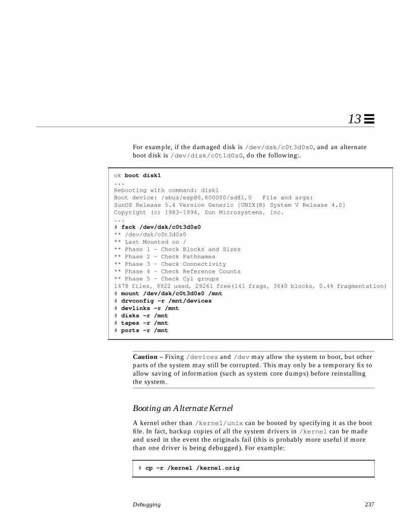
Debugging 237
13
For example, if the damaged disk is /dev/dsk/c0t3d0s0 , and an alternateboot disk is /dev/disk/c0t1d0s0 , do the following:.
Caution – Fixing /devices and /dev may allow the system to boot, but otherparts of the system may still be corrupted. This may only be a temporary fix toallow saving of information (such as system core dumps) before reinstallingthe system.
Booting an Alternate Kernel
A kernel other than /kernel/unix can be booted by specifying it as the bootfile. In fact, backup copies of all the system drivers in /kernel can be madeand used in the event the originals fail (this is probably more useful if morethan one driver is being debugged). For example:
ok boot disk1...Rebooting with command: disk1Boot device: /sbus/esp@0,800000/sd@1,0 File and args:SunOS Release 5.4 Version Generic [UNIX(R) System V Release 4.0]Copyright (c) 1983-1994, Sun Microsystems, Inc....# fsck /dev/dsk/c0t3d0s0** /dev/dsk/c0t3d0s0** Last Mounted on /** Phase 1 - Check Blocks and Sizes** Phase 2 - Check Pathnames** Phase 3 - Check Connectivity** Phase 4 - Check Reference Counts** Phase 5 - Check Cyl groups1478 files, 9922 used, 29261 free(141 frags, 3640 blocks, 0.4% fragmentation)# mount /dev/dsk/c0t3d0s0 /mnt# drvconfig -r /mnt/devices# devlinks -r /mnt# disks -r /mnt# tapes -r /mnt# ports -r /mnt
# cp -r /kernel /kernel.orig
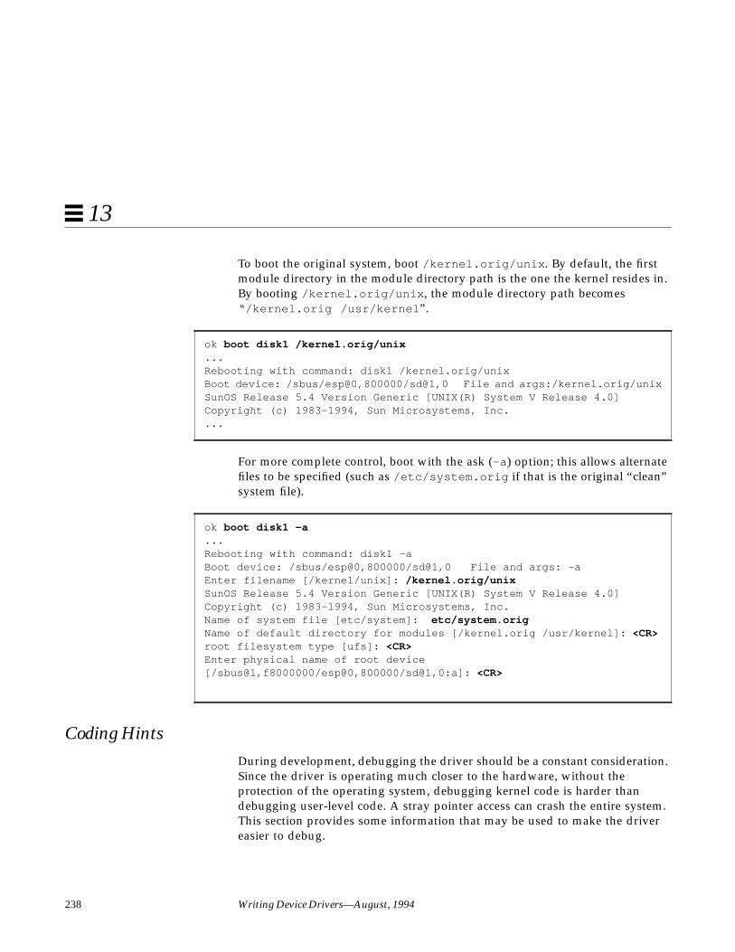
238 Writing Device Drivers—August, 1994
13
To boot the original system, boot /kernel.orig/unix . By default, the firstmodule directory in the module directory path is the one the kernel resides in.By booting /kernel.orig/unix , the module directory path becomes“/kernel.orig /usr/kernel ”.
For more complete control, boot with the ask (-a ) option; this allows alternatefiles to be specified (such as /etc/system.orig if that is the original “clean”system file).
Coding HintsDuring development, debugging the driver should be a constant consideration.Since the driver is operating much closer to the hardware, without theprotection of the operating system, debugging kernel code is harder thandebugging user-level code. A stray pointer access can crash the entire system.This section provides some information that may be used to make the drivereasier to debug.
ok boot disk1 /kernel.orig/unix...Rebooting with command: disk1 /kernel.orig/unixBoot device: /sbus/esp@0,800000/sd@1,0 File and args:/kernel.orig/unixSunOS Release 5.4 Version Generic [UNIX(R) System V Release 4.0]Copyright (c) 1983-1994, Sun Microsystems, Inc....
ok boot disk1 -a...Rebooting with command: disk1 -aBoot device: /sbus/esp@0,800000/sd@1,0 File and args: -aEnter filename [/kernel/unix]: /kernel.orig/unixSunOS Release 5.4 Version Generic [UNIX(R) System V Release 4.0]Copyright (c) 1983-1994, Sun Microsystems, Inc.Name of system file [etc/system]: etc/system.origName of default directory for modules [/kernel.orig /usr/kernel]: <CR>root filesystem type [ufs]: <CR>Enter physical name of root device[/sbus@1,f8000000/esp@0,800000/sd@1,0:a]: <CR>

Debugging 239
13
Process Layout
SunOS 5.x operating system processes follow the definition given in the SystemV Application Binary Interface, SPARC Processor Supplement (also known as theABI). A standard process looks similar to this:
The ABI specifies the system portion of a process’ virtual address space is inthe high end, and may occupy no more than 512 megabytes. In other words, allkernel addresses will be 0xE0000000 or higher. Some implementations mayuse less kernel space, and so begin at a higher address. This fact can be usedwhen debugging: if pointers point below the address 0xE0000000, theyprobably are user addresses.
System Support
The system provides a number of routines that can aid in debugging; they aredocumented in Section 9F of the man Pages(9F): DDI and DKI Kernel Functions.
cmn_err( )
cmn_err (9F) is the function to use to print messages to the console from thekernel. See cmn_err (9F) and “Printing Messages” on page 55 for moreinformation on its use.
0
0xFFFFFFFF
Text
Stack
System
Data

240 Writing Device Drivers—August, 1994
13
Note – Though printf() and uprintf() currently exist, they should not beused if the driver is to be Solaris DDI-compliant.
An example from the probe (9E) routine might be to print a message if thedevice is not found. Normally, probe (9E) routines should not print messages ifthe device is not there.
if (ddi_pokec(dip, ®p->csr, ENABLE_INTERRUPTS) != DDI_SUCCESS) { cmn_err(CE_NOTE, “%s not found.”, ddi_get_name(dip)); return (DDI_PROBE_FAILURE);}
A handy format for printing device register bits is %b. See cmn_err (9F) forinformation on how to use it.
ASSERT( )
void ASSERT(int expression)
ASSERT(9F) can be used to assure that a condition is true at some point in theprogram. It is a macro, and what it does depends on whether or not the symbolDEBUG is defined (from <sys/debug.h> ). If DEBUG is not defined, the macroexpands to nothing and the expression is not evaluated. If DEBUG is defined,the expression is evaluated, and if the value is zero a message is printed andthe system panics.
For example, if at a point in the driver a pointer should be non-NULL—and if itis not, something is seriously wrong—the following assertion could be used:
ASSERT(ptr != NULL);
If compiled with DEBUG defined, and the assertion fails, a panic occurs:
panic: assertion failed: ptr != NULL, file: driver.c, line: 56
Note – Because ASSERT(9F) uses DEBUG, it is suggested that any conditionaldebugging code should also be based on DEBUG, rather than with a driversymbol (such as MYDEBUG). Otherwise, for ASSERT(9F) to function properly,DEBUG must be defined whenever MYDEBUG is defined.
Assertions are an extremely valuable form of active documentation.
Debugging 241
13
mutex_owned( )
int mutex_owned(kmutex_t *mp);
A significant portion of driver development involves properly handlingmultiple threads. Comments should always be used when a mutex is acquired,and are even more useful when an apparently necessary mutex is not acquired.To determine if a mutex is held by a thread, use mutex_owned (9F) withinASSERT(9F):
void helper(void){
/* this routine should always be called with the mu mutex held */ASSERT(mutex_owned(&xsp->mu));...
}
Future releases of Solaris may only support the use of mutex_owned(9F)within ASSERT(9F) by not defineing mutex_owned(9F) unless thepreprocessor symbol DEBUG is defined.
Conditional Compilation and Variables
There are two common ways to place debugging code in a driver: conditionallycompiling code based on a preprocessor symbol such as DEBUG, or using aglobal variable. Conditional compilation has the advantage that unnecessarycode can be removed in the production driver. Using a variable allows theamount of debugging output to be chosen at run time, such as by setting adebugging level at run time with an I/O control or through a debugger.Commonly, these two methods are combined.
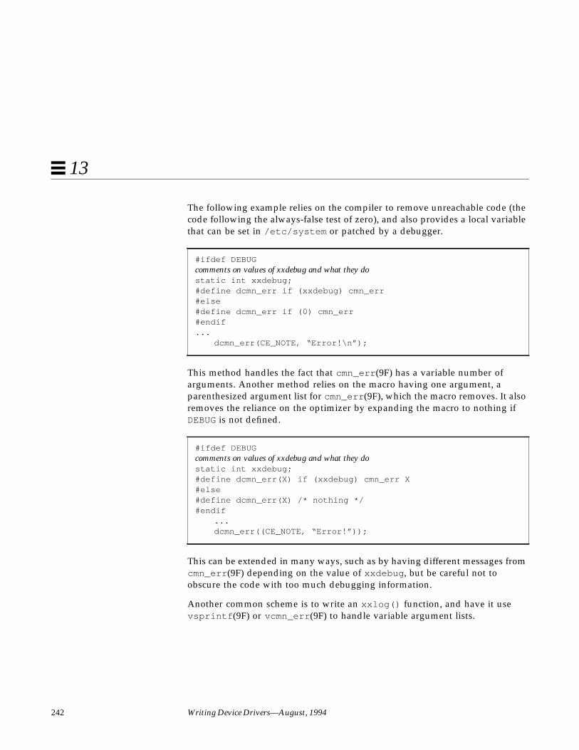
242 Writing Device Drivers—August, 1994
13
The following example relies on the compiler to remove unreachable code (thecode following the always-false test of zero), and also provides a local variablethat can be set in /etc/system or patched by a debugger.
This method handles the fact that cmn_err (9F) has a variable number ofarguments. Another method relies on the macro having one argument, aparenthesized argument list for cmn_err (9F), which the macro removes. It alsoremoves the reliance on the optimizer by expanding the macro to nothing ifDEBUG is not defined.
This can be extended in many ways, such as by having different messages fromcmn_err (9F) depending on the value of xxdebug , but be careful not toobscure the code with too much debugging information.
Another common scheme is to write an xxlog() function, and have it usevsprintf (9F) or vcmn_err (9F) to handle variable argument lists.
#ifdef DEBUGcomments on values of xxdebug and what they dostatic int xxdebug;#define dcmn_err if (xxdebug) cmn_err#else#define dcmn_err if (0) cmn_err#endif...
dcmn_err(CE_NOTE, “Error!\n”);
#ifdef DEBUGcomments on values of xxdebug and what they dostatic int xxdebug;#define dcmn_err(X) if (xxdebug) cmn_err X#else#define dcmn_err(X) /* nothing */#endif
...dcmn_err((CE_NOTE, “Error!”));

Debugging 243
13
The Optimizer and volatile
The volatile keyword must be used when declaring any variable that willreference a device register, or the optimizer may optimize important accessesaway. This is very important since not using volatile can result in bugs thatare very difficult to track down. See “volatile” on page 69 for moreinformation.
Using Existing DriversUsing existing drivers with a user program is a good way to see if the kernelsees the device. This allows the device to be debugged without the need for thedevice-specific driver, and separates device debugging from driver debugging.Depending on the driver and device, mmap(2) , or read(2) and write(2)(possibly with lseek(2) ) may be used.
The “mem” and “kmem” drivers access physical memory and kernel memory,respectively. /dev/mem is used to provide a core memory image to debuggerssuch as adb (1).
To examine kernel memory from a user program, consider using the libkvmroutines (see section kvm_open (3K)) for a (slightly) portable way. Be awarethat kernel structures change frequently, so any code that examines the kernelis likely to need changes in future releases or on other platforms.
For devices, there are two bus space drivers, “vmemem” and “sbusmem”.These allow access to devices on the bus without a driver. After verifying thatthe device is accessible through the PROM (see “The PROM on SPARCMachines” on page 26), these drivers can verify that it is accessible by SunOS.However, special handling requiring knowledge of the device (such asinterrupt handling and DMA) can not be performed by these drivers. Becareful to not compromise system security (such as by giving non-root usersaccess to the special files for these drivers), or system integrity (by accessingother devices).
This program opens the “sbusmem” driver for the slot the bwtwo is in andperforms the same operations that were done previously with the PROM (see“Reading and Writing” on page 33).
Code Example 13-1 Accessing bwtwo with the “sbusmem” driver

244 Writing Device Drivers—August, 1994
13
#include <sys/types.h>#include <sys/mman.h>#include <sys/stat.h>#include <fcntl.h>#include <stdio.h>
voidfill(char *base, int count, char val){
register int i;
for(i=0; i < count; i++)*base++ = val;
sleep(2);}
intmain(int argc, char *argv[]){
int fd;caddr_t base;size_t fb_len = 0x20000;off_t fb_offset = 0x800000;
fd = open(“/devices/sbus@1,f8000000/sbusmem@3,0:slot3”,O_RDWR);
if (fd == -1) {perror(“open /devices/sbus@1,f8000000/sbusmem@3,0:slot3”);return (1);
}base = mmap(NULL, fb_len, PROT_READ | PROT_WRITE, MAP_SHARED,
fd, fb_offset);if (base == (caddr_t)-1) {
perror(“mmap of SBus slot 3”);return (1);
}close(fd);
fill(base, 0x20000, 0xff);fill(base, 0x20000, 0);fill(base, 0x18000, 0x55);fill(base, 0x15000, 0x3);fill(base, 0x10000, 0x5);fill(base, 0x5000, 0xf9);
return (0);}

Debugging 245
13
Debugging ToolsThis section describes some programs and files that can be used to debug thedriver at run time.
/etc/system
The /etc/system file is read once while the kernel is booting. It is used to setvarious kernel options. After modifying this file, the system must be rebootedfor the changes to take effect. If a change in the file causes the system not towork, boot with the ask (-a ) option and specify /dev/null as the system file.
The path the kernel uses when looking for modules can be set by changing themoddir variable in the system file. If the driver module is in a working area,such as /home/driver, the following example adds that directory to themodule path:
moddir: /kernel /usr/kernel /home/driver
Caution – Do not allow non-root users to write to the module directory.
The set command is used to set integer variables. To set module variables, themodule name must also be specified:
set module:variable=value
For example, to set the variable xxdebug in the driver “xx ”, use the followingset command:
set xx:xxdebug=1
To set a kernel integer variable, omit the module name. Other assignments arealso supported, such as bitwise ORing a value into an existing value:
set moddebug | 0x80000000
See system (4) for more information.
Note – Most kernel variables are not guaranteed to be present in subsequentreleases.
moddebug is a bit field that controls the module loading process. See<sys/modctl.h> for all its possible values. Here are a few useful ones:

246 Writing Device Drivers—August, 1994
13
0x80000000 – Print messages to the console when loading/unloadingmodules.
0x40000000 – Give more detailed error messages
0x20000000 – Print more detail when loading/unloading (such asincluding the address and size).
0x00001000 – No autounloading drivers: the system will not attempt tounload the device driver when the system resourcesbecome low.
0x00000080 – No autounloading streams: the system will not attempt tounload the streams module when the system resourcesbecome low.
modload and modunload
Since the kernel automatically loads needed modules, and unloads unusedones, these two commands are now obsolete. However, they can be used fordebugging.
modload (1M) can be used to force a module into memory. The kernel mayunload it subsequently, but modload (1M) may be used to insure that the driverhas no unresolved references when loaded.
modunload (1M) can be used to unload a module, given a module ID (whichcan be determined with modinfo (1M)). Unloading a module does notnecessarily remove it from memory. To unload all unloadable modules andforcibly remove them from memory (so that they will be reloaded from theactual object file), use module ID zero:
Note – modload (1M) and modunload (1M) may be removed in a future release.
# modunload -i 0

Debugging 247
13
Saving System Core Dumps
When the system panics, it writes the interesting portions of memory to thedump device (which is usually the swap device). This is a system core dump,similar to the core dumps generated by applications.
To save a core dump, there must be enough space in the swap area to containit. To be safe, the primary swap area should be at least the size of mainmemory (all the information is in main memory, though not all of it isdumped).
savecore (1M) is used to copy the system‘s core image to a file. Normally, thesystem does not examine the swap area for core dumps when it boots. Thismust be enabled in /etc/init.d/sysetup . Change the lines that read:
To:
When savecore (1M) runs, it makes a copy of the kernel that was running(called unix.n ) and dumps a core file (called vmcore.n ) in the specifieddirectory, normally /var/crash/ machine_name. There must be enough space
#### Default is to not do a savecore###if [ ! -d /var/crash/`uname -n` ]#then mkdir -p /var/crash/`uname -n`#fi# echo ‘checking for crash dump...\c ‘#savecore /var/crash/`uname -n`# echo ‘’
#### Default is to not do a savecore##if [ ! -d /var/crash/`uname -n` ]then mkdir -p /var/crash/`uname -n`fi echo ‘checking for crash dump...\c ‘savecore /var/crash/`uname -n` echo ‘’

248 Writing Device Drivers—August, 1994
13
in /var/crash to contain the core dump or it will be truncated. The file willappear larger than it actually is, since it contains holes, so avoid copying it.adb (1) can then be used on the core dump and the saved kernel.
Note – savecore (1M) can be prevented from filling the file system if there isa file called minfree in the directory in which the dump will be saved. Thisfile contains a number of kilobytes to remain free after savecore (1M) has run.However, if not enough space is available, the core file is not saved.
adb and kadb
adb (1) can be used to debug applications or the kernel, though it cannot debugthe kernel interactively (such as by setting breakpoints). To interactively debugthe kernel, use kadb (1M). Both adb (1) and kadb (1M) share a commoncommand set.
adb (1) is a very terse debugger. It does not normally prompt for input (thoughkadb (1M) does).
Starting adb
The command for starting adb to debug a kernel core dump is:
To start adb on a live system, use (as root )::
/dev/ksyms is a special driver that provides an image of the kernel’s symboltable. This can be used to examine the debugging information (traces) thedriver has left in the memory.
When adb (1) responds with ’physmem XXX’ , it is ready for a command.
% adb -k /var/crash/hostname/unix.n /var/crash/hostname/vmcore.n
# adb -k /dev/ksyms /dev/mem
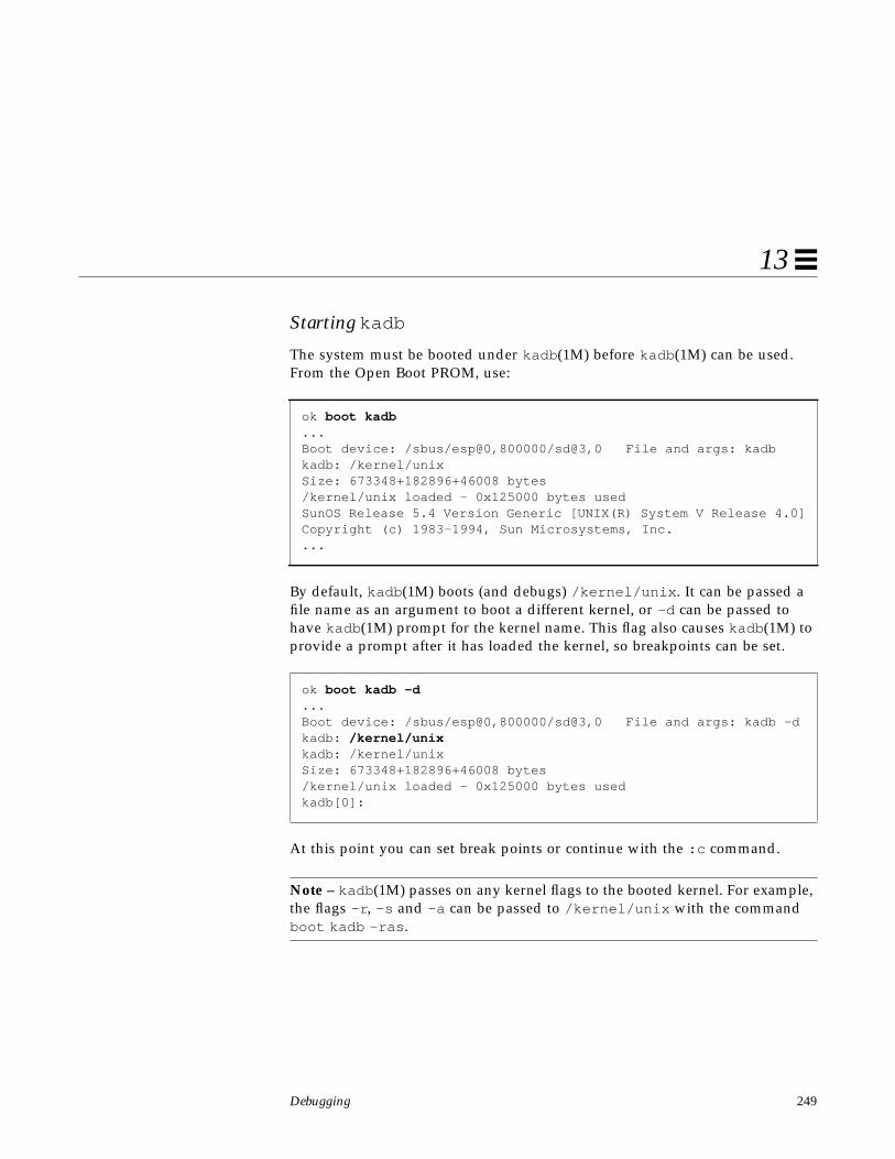
Debugging 249
13
Starting kadb
The system must be booted under kadb (1M) before kadb (1M) can be used.From the Open Boot PROM, use:
By default, kadb (1M) boots (and debugs) /kernel/unix . It can be passed afile name as an argument to boot a different kernel, or -d can be passed tohave kadb (1M) prompt for the kernel name. This flag also causes kadb (1M) toprovide a prompt after it has loaded the kernel, so breakpoints can be set.
At this point you can set break points or continue with the :c command.
Note – kadb (1M) passes on any kernel flags to the booted kernel. For example,the flags -r , -s and -a can be passed to /kernel/unix with the commandboot kadb -ras .
ok boot kadb...Boot device: /sbus/esp@0,800000/sd@3,0 File and args: kadbkadb: /kernel/unixSize: 673348+182896+46008 bytes/kernel/unix loaded - 0x125000 bytes usedSunOS Release 5.4 Version Generic [UNIX(R) System V Release 4.0]Copyright (c) 1983-1994, Sun Microsystems, Inc....
ok boot kadb -d...Boot device: /sbus/esp@0,800000/sd@3,0 File and args: kadb -dkadb: /kernel/unixkadb: /kernel/unixSize: 673348+182896+46008 bytes/kernel/unix loaded - 0x125000 bytes usedkadb[0]:

250 Writing Device Drivers—August, 1994
13
Once the system is booted, sending a break passes control to kadb (1M). Abreak is generated with L1-A, or by ~# if the console is connected through a tipwindow
The number in brackets is the CPU that kadb (1M) is currently executing on;the remaining CPUs are halted. The CPU number is zero on a uniprocessor.Halting the system will also drop to a kadb (1M) prompt.
Warning – Before rebooting or shutting off the power, always halt the systemcleanly (with init 0 or shutdown ). Buffers may not be flushed otherwise. Ifthe shutdown must occur from the boot PROM, make sure to flush bufferswith sync (on the OBP), or ‘g 0’ (on SunMon).
To continue back to SunOS, use :c .
Exiting
To exit either adb (1M) or kadb (1M), use $q .
kadb (1M) can be continued by typing go (on the OBP) or c (on SunMON).
...The system is ready.
test console login: ~stopped at 0xfbd01028: ta 0x7dkadb[0]:
kadb[0]: :c
test console login:
kadb[0]: $qType ‘go’ to resumeok

Debugging 251
13
Warning – No other commands can be performed from the PROM if thesystem is to be continued. PROM commands other than :c (continue) maychange system state that SunOS depends on.
Staying at the kadb (1M) prompt for too long may cause the system to losetrack of the time of day, and cause network connections to time out.
Commands
The general form of an adb (1M)/kadb (1M) command is:
[ address ] [ ,count ] command [;]
If address is omitted, the current location is used (‘.’ also stands for the currentlocation). The address can be a kernel symbol. If count is omitted, it defaults to1.
Commands to adb consist of a verb followed by a modifier or list of modifiers.Verbs can be:
? Print locations starting at address in the executable.
/ Print locations starting at address in the core file.
= Print the value of address itself.
> Assign a value to a variable or register.
< Read a value from a variable or register.
RETURN Repeat the previous command with a count of 1. Increment‘.’.
With ?, / , and =, output format specifiers can be used. Lowercase lettersnormally print 2 bytes, uppercase letters print 4 bytes:
o, O Octal
d,D Decimal
x,X Hexadecimal
u,U Unsigned decimal
f,F 4,8 byte floating point

252 Writing Device Drivers—August, 1994
13
c Print the addressed character
C Print the addressed character using ^ escape notation.
s Print the addressed string.
S Print the addressed string using ^ escape notation.
i Print as machine instructions (disassemble)
a Print the value of `.’ in symbolic form.
w,W Write a 2/4 byte value
Note – Understand exactly what sizes the objects are, and what effectschanging them might have, before making any changes.
For example, to set a bit in the moddebug variable when debugging the driver,first examine the value of moddebug, then OR in the desired bit.
Routines can be disassembled with the ‘i ’ command. This is useful whentracing crashes, since the only information may be the program counter at thetime of the crash. The output has been formatted for readability:
kadb[0]: moddebug/Xmoddebug:moddebug: 0kadb[0]: moddebug/W 0x80000000moddebug: 0x0 = 0x80000000
kadb[0]: strcmp,4?istrcmp:strcmp: ba strcmp + 0x20
ldsb [%o1], %o5add %o0, 0x1, %o0orcc %g0, %o5, %g0
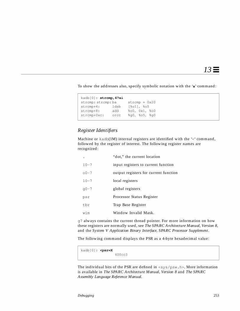
Debugging 253
13
To show the addresses also, specify symbolic notation with the ‘a’ command:
Register Identifiers
Machine or kadb (1M) internal registers are identified with the ‘<‘ command,followed by the register of interest. The following register names arerecognized:
. “dot,” the current location
i0-7 input registers to current function
o0-7 output registers for current function
l0-7 local registers
g0-7 global registers
psr Processor Status Register
tbr Trap Base Register
wim Window Invalid Mask.
g7 always contains the current thread pointer. For more information on howthese registers are normally used, see The SPARC Architecture Manual, Version 8,and the System V Application Binary Interface, SPARC Processor Supplement.
The following command displays the PSR as a 4-byte hexadecimal value:
The individual bits of the PSR are defined in <sys/psw.h> . More informationis available in The SPARC Architecture Manual, Version 8 and The SPARCAssembly Language Reference Manual.
kadb[0]: strcmp,4?aistrcmp: strcmp: ba strcmp + 0x20strcmp+4: ldsb [%o1], %o5strcmp+8: add %o0, 0x1, %o0strcmp+0xc: orcc %g0, %o5, %g0
kadb[0]: <psr=X 400cc3
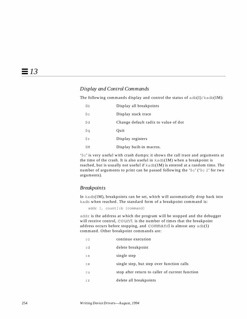
254 Writing Device Drivers—August, 1994
13
Display and Control Commands
The following commands display and control the status of adb (1)/kadb (1M):
$b Display all breakpoints
$c Display stack trace
$d Change default radix to value of dot
$q Quit
$r Display registers
$M Display built-in macros.
‘$c ’ is very useful with crash dumps: it shows the call trace and arguments atthe time of the crash. It is also useful in kadb (1M) when a breakpoint isreached, but is usually not useful if kadb (1M) is entered at a random time. Thenumber of arguments to print can be passed following the ‘$c ’ (‘$c 2 ’ for twoarguments).
Breakpoints
In kadb (1M), breakpoints can be set, which will automatically drop back intokadb when reached. The standard form of a breakpoint command is:
addr [, count]:b [command]
addr is the address at which the program will be stopped and the debuggerwill receive control, count is the number of times that the breakpointaddress occurs before stopping, and command is almost any adb (1)command. Other breakpoint commands are:
:c continue execution
:d delete breakpoint
:s single step
:e single step, but step over function calls
:u stop after return to caller of current function
:z delete all breakpoints

Debugging 255
13
Here is an example of setting a breakpoint in a commonly used routine,scsi_transport (9F). Upon reaching the breakpoint, ‘$c ’ is used to get astack trace. The top of stack is the first function printed. Note that kadb (1M)does not know how many arguments were passed to the function; it alwaysprints six.
Conditional Breakpoints
Breakpoints can also be set to occur only if a certain condition is met. Byproviding a command, the breakpoint will be taken only if the count is reachedor the command returns zero. For example, a breakpoint that occurs only on
kadb[0]: scsi_transport:bkadb[0]: :c
test console login: rootPassword:breakpoint scsi_transport: save %sp, -0x60, %spkadb[0]: $cscsi_transport(0xff09c400,0x3,0x3,0x1,0xff09c534,0xff0a0690)sdstrategy(0xff0a0690,0x3,0xff09c440,0x170,0xff09c534,0xff09c400) + 3d8bwrite(0xff0a0690,0xff1ed400,0x1,0xb,0xff0a06f0,0xf017d9d8) + bcsbupdate(0xf00dcfe8,0xff20f400,0xff0a0690,0x400,0x0,0xff03b000)+ 9cufs_update(0xff034c80,0x3,0xff034cac,0xff2ac764,0xff03b000,0xf00dfe8) + 198ufs_sync(0x0,0x10000,0xff007980,0x1e,0xf00d8e38,0xf00d8e38) + 8fsflush(0xf00dd330,0xf00e0830,0x1af,0x2,0xf00f3ab8,0xf00b8254) + 568kadb[0]: :sstopped at scsi_transport+4: ld [%i0 + 0x4], %o0kadb[0]: $bbreakpointscount bkpt command1 scsi_transportkadb[0]: scsi_transport:dkadb[0]: :c

256 Writing Device Drivers—August, 1994
13
certain I/O controls could be set in the driver’s ioctl (9E) routine. Here is anexample of breaking only in the sdioctl () routine if the DKIOGVTOC (getvolume table of contents) I/O control occurs.
Adding four to sdioctl skips to the second instruction in the routine,bypassing the save instruction that establishes the stack. The ‘<i1 ’ refers tothe first input register, which is the second parameter to the routine (the cmdargument of ioctl (9E)). The count of zero is impossible to reach, so it stopsonly when the command returns zero, which is when ‘i1 - 0x40B ’ is true. Thismeans i1 contains 0x40B (the value of the ioctl command, determined byexamining the header file).
To force the breakpoint to be reached, the prtvtoc (1M) command is used. Itknown to issue this I/O control:
kadb (1M) cannot always determine where the bottom of the stack is. In theabove example, the calls to Syssize and ?(?) are not part of the stack.
kadb[0]: sdioctl+4,0:b <i1-0x40Bkadb[0]: $bbreakpointscount bkpt command0 sdioctl+4 <i1-0x40Bkadb[0]: :c
# prtvtoc /dev/rdsk/c0t3d0s0breakpoint sdioctl+4: mov %i0, %o0kadb[0]: $csdioctl(0x800018,0x40b,0xeffffc24,0x1,0xff22fa80,0xf01e9918) + 4ioctl(0xf01e9e90,0xf01e9918,0x1,0x40b,0xff2ab380,0xff0894b4) + 1ecsyscall(0xf00c1c54) + 4d4.syscall(0x3) +8c?(?) + 7fffffffSyssize(0x3,0xeffffc24,0xeffffd6c,0x5403148,0x0,0x5452ea0) + 20338Syssize(0x3,0xefffff7c,0xeffffc24,0x80,0x3,0x0)+ fb70Syssize(0xefffff7c,0x2000,0x1,0x1,0x1,0x3) + f51cSyssize(0x2,0xeffffee4,0xeffffef0,0x22c00,0x0,0xffffffff) + eb8c

Debugging 257
13
Macros
adb (1) and kadb (1M) support macros. adb (1) macros are in/usr/kvm/lib/adb , while kadb (1M)’s macros are built-in and can bedisplayed with $M. Most of the existing macros are for private kernelstructures. New macros for adb can be created with adbgen (1).
Macros are used in the form:
[ address ] $<macroname
threadlist is a useful macro that displays the stacks of all the threads in thesystem. This macro that does not take an address, and can generate a lot ofoutput, so be ready to use Control-S and Control-Q to start/stop if necessary(this is another good reason to use a tip window). Control-C can be used toabort the listing.:
kadb[0]: $<threadlistthread_id f0141ee0
?() + 1edata address not found
thread_id f0165ee0?(0xf00e24e0,0xf00e24e0,0xff004000,0xc,0x0,0x4000e0) + 1ecallout_thread(0xff004090,0xf00d7d9a,0xf00e24e0,0xf00ac6c0,0x0,0xf004000) + 2c
thread_id f016bee0?(0xf00e04d0,0xf00e04d0,0x80b5f7ff,0x1,0x0,0x4000e0) + 1ebackground(0x0,0x0,0x0,0xf00e23ac,0x0,0xf00e04d0) + 64
thread_id f016eee0?(0xf00dd884,0xf00dd884,0x80b777ff,0x1,0x0,0x4000e0) + 1efreebs(0x0,0x0,0xf00e2388,0xff21d270,0xf00e24a0,0xf00dd884) + 2c^C

258 Writing Device Drivers—August, 1994
13
Another useful macro is thread . Given a thread ID, it prints thecorresponding thread structure. This can be used to look at a certain threadfound with the threadlist macro, to look at the owner of a mutex, or to lookat the current thread.
Note – There is no type information kept in the kernel, so using a macro on aninappropriate object will result in garbage output.
Macros do not necessarily output all the fields of the structures, nor is theoutput necessarily in the order given in the structure definition. Occasionally,memory may need to be dumped for certain structures, and then matched withthe structure definition in the kernel header files.
Warning – The driver should have knowledge only of headers and structureslisted in Section 9S of the man Pages(9S): DDI and DKI Data Structures, eventhough interesting knowledge may be uncovered while debugging.
kadb[0]: <g7$<thread0xf0141ee0:
link stk stksize0 f0141ee0 ee0
0xf0141eec:affinity affcnt bind_cpu1 1 -1
...

Debugging 259
13
Example: adb on a Core Dump
During the development of the example ramdisk driver, the system crasheswith a data fault when running mkfs (1M).
savecore (1M) was not enabled. After enabling it (See “Saving System CoreDumps” on page 247), the system is rebooted. The crash is then recreated byrunning mkfs (1M) again. When the system comes up, it saves the kernel andthe core file, which can then be examined with adb (1):
The first step is to examine the stack to determine where the system was whenit crashed:
test# mkfs -F ufs -o nsect=8,ntrack=8,free=5 /devices/pseudo/ramdisk:0,raw 1024BAD TRAPmkfs: Data faultkernel read fault at addr=0x4, pme=0x0Sync Error Reg 80<INVALID>pid=280, pc=0xff2f88b0, sp=0xf01fe750, psr=0xc0, context=2g1-g7: ffffff98, 8000000, ffffff80, 0, f01fe9d8, 1, ff1d4900Begin traceback... sp = f01fe750Called from f0098050,fp=f01fe7b8,args=1180000 f01fe878 ff1ed280 ff1ed280 2 ff2f8884Called from f0097d94,fp=f01fe818,args=ff24fd40 f01fe878 f01fe918 0 0 ff2c9504Called from f0024e8c,fp=f01fe8b0,args=f01fee90 f01fe918 2 f01fe8a4 f01fee90 3241cCalled from f0005a28,fp=f01fe930,args=f00c1c54 f01fe98c 1 f00b9d58 0 3Called from 15c9c,fp=effffca0,args=5 3241c 200 0 0 7fe00End traceback...panic: Data fault
# cd /var/crash/test# lsbounds unix.0 vmcore.0# adb -k unix.0 vmcore.0physmem ac0
$ccomplete_panic(0x0,0x1,0xf00b6c00,0x7d0,0xf00b6c00,0xe3) + 114do_panic(0xf00be7ac,0xf0269750,0x4,0xb,0xb,0xf00b6c00) + 1cdie(0x9,0xf0269704,0x4,0x80,0x1,0xf00be7ac) + 5ctrap(0x9,0xf0269704,0x4,0x80,0x1,0xf02699d8) + 6b4

260 Writing Device Drivers—August, 1994
13
This stack trace is not very helpful initially, since the ramdisk routines are noton the stack trace. However, there is a useful bit of information: the call totrap() . The first argument to trap() is the trap type—in this case 9—whichis a T_DATA_FAULT trap (from <sys/trap.h> ). See The SPARC Architecture,Version 8 manual for more information.
The second argument to trap () is a pointer to a regs structure containing thestate of the registers at the time of the trap.
Note that the PC was ff2dd8b0 when the trap occurred. The next step is todetermine which routine that is in:
That PC corresponds to rd_write (), which is a routine in the ramdisk driver.The bug is in the ramdisk write routine, and occurs during an ld (load)instruction. This load instruction is dereferencing the value of o2+4 , so thenext step is to determine the value of o2 .
Note – Using the $r command to examine the registers is inappropriatebecause the registers have been reused in the trap routine. Instead, examinethe value of o2 from the regs structure.
0xf0269704$<regs0xf0269704: psr pc npc
c0 ff2dd8b0 ff2dd8b40xf0269710: y g1 g2 g3
e0000000 ffffff98 8000000 ffffff800xf0269720: g4 g5 g6 g7
0 f02699d8 1 ff22c8000xf0269730: o0 o1 o2 o3
f02697a0 ff080000 19000 ef7090000xf0269740: o4 o5 o6 o7
8000 0 f0269750 7fffffff
ff2dd8b0/ird_write+0x2c: ld [%o2 + 0x4], %o3

Debugging 261
13
o2 has the value 19000 in the regs structure. Valid kernel addresses areconstrained to be above 0xE0000000 by the ABI, so this address is probably auser one. The ramdisk does not deal with user addresses though, so this issomething the ramdisk write routine should not be dereferencing.
Now, where this occurs in relation to the complete routine must be determined,so that the assembly language can be matched to the C code. To do this, theroutine is disassembled up to the problem instruction, which occurs 2c bytesinto the routine. Each instruction is 4 bytes in size, so 2c/4 or 0xb additionalinstructions should be displayed:
The crash occurs a few instructions after a call to getminor (9F). Examiningthe ramdisk.c source file these lines stand out in rd_write :
int instance = getminor(dev);rd_devstate_t *rsp;
if (uiop->uio_offset >= rsp->ramsize)return (EINVAL);
Notice that rsp is never initialized. This is the problem. It is fixed by includingthe correct call to ddi_get_soft_state (9F) (since the ramdisk driver usesthe soft state routines to do state management):
int instance = getminor(dev);rd_devstate_t *rsp = ddi_get_soft_state(rd_state, instance);
if (uiop->uio_offset >= rsp->ramsize)return (EINVAL);
rd_write,c/ird_write:rd_write: sethi %hi(0xfffffc00), %g1
add %g1, 0x398, %g1 ! ffffff98save %sp, %g1, %spst %i0, [%fp + 0x44]st %i1, [%fp + 0x48]st %i2, [%fp + 0x4c]ld [%fp + 0x44], %o0call getminornopst %o0, [%fp - 0x4]ld [%fp - 0x8], %o2ld [%o2 + 0x4], %o3
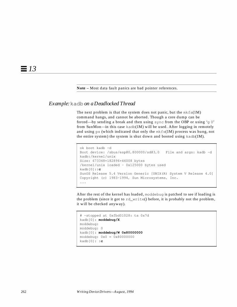
262 Writing Device Drivers—August, 1994
13
Note – Most data fault panics are bad pointer references.
Example: kadb on a Deadlocked Thread
The next problem is that the system does not panic, but the mkfs (1M)command hangs, and cannot be aborted. Though a core dump can beforced—by sending a break and then using sync from the OBP or using ‘g 0 ’from SunMon—in this case kadb (1M) will be used. After logging in remotelyand using ps (which indicated that only the mkfs (1M) process was hung, notthe entire system) the system is shut down and booted using kadb (1M).
After the rest of the kernel has loaded, moddebug is patched to see if loading isthe problem (since it got to rd_write () before, it is probably not the problem,it will be checked anyway).
ok boot kadb -dBoot device: /sbus/esp@0,800000/sd@3,0 File and args: kadb -dkadb:/kernel/unixSize: 673348+182896+46008 bytes/kernel/unix loaded - 0x125000 bytes usedkadb[0]: :cSunOS Release 5.4 Version Generic [UNIX(R) System V Release 4.0]Copyright (c) 1983-1994, Sun Microsystems, Inc....
# ~stopped at 0xfbd01028: ta 0x7dkadb[0]: moddebug/Xmoddebug:moddebug: 0kadb[0]: moddebug/W 0x80000000moddebug: 0x0 = 0x80000000kadb[0]: :c

Debugging 263
13
modload (1M) is used to load the driver, to separate module loading from thereal access:
It loads fine, so loading is not the problem. The condition is recreated withmkfs (1M).
It hangs. At this point, kadb (1M) is entered and the stack examined:
# modload /home/driver/drv/ramdiskload ‘/usr/kernel/drv/ramdisk’ id 61 loaded @ 0xff335000 size 3304installing ramdisk, module id 61.
# mkfs -F ufs -o nsect=8,ntrack=8,free=5 /devices/pseudo/ramdisk@0:c,raw 1024ramdisk0: misusing 524288 bytes of memory
~stopped at 0xfbd01028: ta 0x7dkadb[0]: $c_end() + bc1eb40debug_enter(0xfbd01000,0xff1a7054,0x0,0x0,0xb,0xff1a7000) + 88zs_high_intr(0xff1a0230) + 19c_level1(0xf0141ee0) + 404idle(0x0,0x0,0x0,0xf0171ee0,0x0,0x1) + 28

264 Writing Device Drivers—August, 1994
13
It does not look like the current thread is the problem, so the entire thread listis checked for hung threads:
Of all the threads, only one has a stack trace that references the ramdisk driver.It happens to be the last one. It seems that the process running mkfs (1M) isblocked in biowait (9F), after a call to physio (9F). biowait (9F) takes abuf (9S) structure as a parameter, the next step is to examine the buf (9S)structure:
kadb[0]: $<threadlistthread_id f0141ee0
?(0xfbd01000,0xff1a7054,0x0,0x0,0xb,0xff1a7000)+ 1ezs_high_intr(0xff1a0230) + 19c_level1(0xf0141ee0) + 404idle(0x0,0x0,0x0,0xf0171ee0,0x0,0x1) + 28
thread_id f0165ee0?(?) + 1ecv_wait(0xf00e24e0,0xf00e24e0,0xff004000,0xb,0x0,0x4000e4)callout_thread(0xff004090,0xf00d7d9a,0xf00e24e0,0xf00ac6c0,0x0,0xff004000) + 2c
thread_id f016bee0...
thread_id ff11c600?(?) + 1ebiowait(0xf01886d0,0x0,0x7fe00,0x200,0xf00e085c,0x3241c)physio(0xff196120,0xf01886d0,0xf01888a4,0x3241c,0x0,0xf0188878)+ 338rd_write(0x1180000,0xf0188878,0xff19b680,0xff19b680,0x2,0xff335884) + 8crdwr(0xff1505c0,0xf0188878,0xf0188918,0x0,0x0,0xff24dd04) + 138rw(0xf0188e90,0xf0188918,0x2,0xf01888a4,0xf0188e90,0x3241c) + 11csyscall(0xf00c1c54) + 4d4
kadb[0]: f01886d0$<buf0xf01886d0: flags
1290xf01886d4: forw back av_forw av_back
ff24dd04 72616d64 69736b3a 302c72610xf01886e8: count bufsize error edev
512 770 0 11800000xf01886ec: addr blkno resid proc
3241c 3ff 0 ff26f0000xf0188714: iodone vp pages
0 f01888a4 efffff68

Debugging 265
13
The resid field is 0, which indicates that the transfer is complete. physio (9F)is still blocked, however. Examining the physio (9F) manual page points outthat biodone(9F) should be called to unblock biowait (9F). This is theproblem; rd_strategy ( ) did not call biodone (9F). Adding a call tobiodone (9F) before returning fixes this problem.
TestingOnce a device driver is functional, it should be thoroughly tested before it isdistributed. In addition to the testing done to traditional UNIX device drivers,Solaris 2.x drivers require testing of Solaris 2.x features such as dynamicloading and unloading of drivers and multithreading.
Configuration Testing
A driver’s ability to handle multiple configurations is very important, and is apart of the test process. Once the driver is working on a simple, or default,configuration, additional configurations should be tested. Depending on thedevice, this may be accomplished by changing jumpers or DIP switches. If thenumber of possible configurations is small, all of them should be tried. If thenumber is large, various classes of possible configurations should be defined,and a sampling of configurations from each class should be tested. Thedesignation of such classes depends on how the different configurationparameters might interact, which in turn depends on the device and on howthe driver was written.
For each configuration, the basic functions must be tested, which includeloading, opening, reading, writing, closing, and unloading the driver. Anyfunction that depends on the configuration deserves special attention. Forexample, changing the base memory address of device registers is not likely toaffect the behavior of most driver functions; if the driver works well with oneaddress, it is likely to work as well with a different address, providing theconfiguration code allows it to work at all. On the other hand, a special I/Ocontrol call may have different effects depending on the particular deviceconfiguration.
266 Writing Device Drivers—August, 1994
13
Loading the driver with varying configurations assures that the probe (9E) andattach (9E) entry points can find the device at different addresses. For basicfunctional testing, using regular UNIX commands such as cat (1) or dd(1M) isusually sufficient for character devices. Mounting or booting may be requiredfor block devices.
Functionality Testing
After a driver has been run through configuration testing, all of itsfunctionality should be thoroughly tested. This requires exercising theoperation of all of the driver’s entry points. In addition to the basic functionaltests done in configuration testing, full functionality testing requires testing therest of the entry points and functions to obtain confidence that the driver cancorrectly perform all of its functions.
Many drivers will require custom applications to test functionality, but basicdrivers for devices such as disks, tapes, or asynchronous boards can be testedusing standard system utilities. All entry points should be tested in thisprocess, including mmap(9E), poll (9E) and ioctl (9E), if applicable. Theioctl (9E) tests may be quite different for each driver, and for nonstandarddevices a custom testing application will be required.
Error Handling
A driver may perform correctly in an ideal environment, but fail to handlecases where a device encounters an error or an application specifies erroneousoperations or sends bad data to the driver. Therefore, an important part ofdriver testing is the testing of its error handling.
All of a driver’s possible error conditions should be exercised, including errorconditions for actual hardware malfunctions. Some hardware error conditionsmay be difficult to induce, but an effort should be made to cause them or tosimulate them if possible. It should always be assumed that all of theseconditions will be encountered in the field. Cables should be removed orloosened, boards should be removed, and erroneous user application codeshould be written to test those error paths.
Debugging 267
13
Stress, Performance, and Interoperability Testing
To help ensure that the driver performs well, it should be subjected to vigorousstress testing. Running single threads through a driver will not test any of thelocking logic and might not test condition variable waits. Device operationsshould be performed by multiple processes at once in order to cause severalthreads to execute the same code simultaneously. The way this should be donedepends on the driver; some drivers will require special testing applications,but starting several UNIX commands in the background will be suitable forothers. It depends on where the particular driver uses locks and conditionvariables. Testing a driver on a multiprocessor machine is more likely toexpose problems than testing on a single processor machine.
Interoperability between drivers must also be tested, particularly becausedifferent devices can share interrupt levels. If possible, configure anotherdevice at the same interrupt level as the one being tested, and whether thedriver correctly claims its own interrupts and otherwise operates correctlyunder the stress tests described above should be tested. Stress tests should berun on both devices at once. Even if the devices do not share an interrupt level,this test can still be valuable; for example, if serial communication devices startto experience errors while a network driver is being tested, that could indicatethat the network driver is causing the rest of the system to encounter interruptlatency problems.
Performance of a driver under these stress tests should be measured usingUNIX performance measuring tools. This can be as simple as using the time (1)command along with commands used for stress tests.
DDI/DKI Compliance Testing
To assure compatibility with later releases and reliable support for the currentrelease, every driver should be Solaris 2.4 DDI/DKI compliant. One way todetermine if the driver is compliant is by inspection. The driver can be visuallyinspected to ensure that only kernel routines and data structures specified insections 9F and 9S of the Solaris 2.4 Reference Manual AnswerBook are used.
In addition, the Solaris 2.4 Driver Developer Kit (DDK) now includes a DDIcompliance tool (DDICT) that checks device driver C source code for non-DDI/DKI compliance and issues either error or warning messages when itfinds non-compliant code. SunSoft recommends that all drivers be written topass DDICT. After the DDK has been installed, the DDICT can be found in:

268 Writing Device Drivers—August, 1994
13
/opt/SUNWddk/driver_dev/bin/ddict
A new manual page describing DDICT is available in:
/opt/SUNWddk/driver_dev/ddict/man/man1/ddict.1
Installation and Packaging Testing
Drivers are delivered to customers in packages. A package can be added andremoved from the system using a standard, documented mechanism (see theSunOS 5.4 Application Packaging and Installation Guide). Test that the driver hasbeen correctly packaged to ensure that the end user will be able to add it toand remove it from a system.
In testing, the package should be installed and removed from every type ofmedia on which it will be released, and on several system configurations.Packages must not make unwarranted assumptions about the directoryenvironment of the target system. Certain valid assumptions may be madeabout where standard kernel files are kept, however. It is a good idea to testthe adding and removing of packages on newly-installed machines that havenot been modified for a development environment. It is a common packagingerror for a package to use a tool or file that exists only in a developmentenvironment, or only on the driver writer’s own development system. Forexample, no tools from Source Compatibility package, SUNWscpu, should beused in driver installation programs.
The driver installation must be tested on a minimal Solaris system without anyof the optional packages installed.
Testing Specific Types of Drivers
Since each type of device is different, it is difficult to describe how to test themall specifically. This section provides some information about how to testcertain types of standard devices.
Tape Drivers
Tape drivers should be tested by performing several archive and restoreoperations. The cpio (1) and tar (1) commands may be used for this purpose.The dd(1M) command can be used to write an entire disk partition to tape,which can then be read back and written to another partition of the same size,
Debugging 269
13
and the two copies compared. The mt(1) command will exercise most of theI/O controls that are specific to tape drivers (see mtio (7)); all of the optionsshould be attempted. The error handling of tape drivers can be tested byattempting various operations with the tape removed, attempting writes withthe write protect on, and removing power during operations. Tape driverstypically implement exclusive-access open (9E) calls, which should be tested byhaving a second process try to open the device while a first process already hasit open.
Disk Drivers
Disk drivers should be tested in both the raw and block device modes. Forblock device tests, a new file system should be created on the device andmounted. Multiple file operations can be performed on the device at this time.
Note – The file system uses a page cache, so reading the same file over andover again will not really be exercising the driver. The page cache can be forcedto retrieve data from the device by memory mapping the file (with mmap(2)),and using msync (2) to invalidate the in-memory copies.
Another (unmounted) partition of the same size can be copied to the rawdevice and then commands such as fsck (1M) can be used to verify thecorrectness of the copy. The new partition can also be mounted and comparedto the old one on a file-by-file basis.
Asynchronous Communication Drivers
Asynchronous drivers can be tested at the basic level by setting up a loginline to the serial ports. A good start is if a user can log in on this line. Tosufficiently test an asynchronous driver, however, all of the I/O controlfunctions must be tested, and many interrupts at high speed must occur. A testinvolving a loopback serial cable and high speed communication will help testthe reliability of the driver. Running uucp (1C) over the line also provides someexercise; note, however, that uucp (1C) performs its own error handling, so it isimportant to verify that the driver is not reporting excessive numbers of errorsto the uucp (1C) process.
These types of devices are usually STREAMS-based.

270 Writing Device Drivers—August, 1994
13
Network Drivers
Network drivers may be tested using standard network utilities. ftp (1) andrcp (1) are useful because the files can be compared on each end of thenetwork. The driver should be tested under heavy network loading, so variouscommands should be run by multiple processes. Heavy network loadingmeans:
• There is a lot of traffic to the test machine.• There is heavy traffic among all machines on the network.
Network cables should be unplugged while the tests are executing, and thedriver should recover gracefully from the resulting error conditions. Anotherimportant test is for the driver to receive multiple packets in rapid succession(‘‘back-to-back’’ packets). In this case, a relatively fast host on a lightly-loadednetwork should send multiple packets in quick succession to the machine withthe driver being tested. It should be verified that the receiving driver does notdrop the second and subsequent packets.
These types of devices are usually STREAMS-based.

271
Converting a Device Driver toSunOS 5.4 A
This chapter is a guide to the differences between SunOS 4.x and SunOS 5.xdevice drivers. Some simple drivers can be ported easily, but to properlyhandle the multithreaded environment, most drivers will need to be rethoughtand rewritten.
Before Starting the Conversion
Review Existing Functionality
Make sure the driver’s current functionality is well understood: the way itmanages the hardware, and the interfaces it provides to applications (ioctl (2)states the device is put in for example). Maintain this functionality in the newdriver.
Read the Manual
This chapter is not a substitute for the rest of this book. Make sure you haveaccess to the SunOS 5.4 Reference Manuals.

272 Writing Device Drivers—August, 1994
A
ANSI C
The unbundled Sun C compiler is now ANSI C compliant. Most ANSI Cchanges are beyond the scope of this book. There are a number of good ANSIC books available from local bookstores. The following two books are goodreferences:
• Kernighan and Ritchie, The C Language, Second Edition, 1988, Prentice-Hall
• Harbison and Steele, C: A Reference Manual, Second Edition, 1987,Prentice-Hall
Development Environment
DDI/DKI
The DDI/DKI is a new name for the routines formerly called “kernel supportroutines” in the SunOS 4.x Writing Device Drivers manual, and for the “well-known” entry points in the SunOS 4.x cdevsw and bdevsw structures. Theintent is to specify a set of interfaces for drivers that provide a binary andsource code interface. If a driver uses only kernel routines and structuresdescribed in Section 9 of the man Pages(9): DDI and DKI Overview, it is calledSolaris 2.4 DDI/DKI-compliant. A Solaris 2.4 DDI/DKI-compliant driver islikely to be binary compatible across Sun Solaris platforms with the sameprocessor (SPARC), and binary compatible with future releases of Solaris onplatforms the driver works on.
Things to Avoid
Many architecture-specific features have been hidden from driver writersbehind DDI/DKI interfaces. Specific examples are elements of the dev_infostructure, user structure, proc structure, and page tables. If the driver hasbeen using unadvertised interfaces, it must be changed to use DDI/DKIinterfaces that provide the required functionality. If the driver continues to useunadvertised interfaces, it loses all the source and binary compatibility featuresof the DDI/DKI. For example, previous releases had an undocumented routinecalled as_fault ( ) that could be used to lock down user pages in memory.This routine still exists, but is not part of the DDI/DKI, so it should not beused. The only documented way to lock down user memory is to usephysio (9F).

Converting a Device Driver to SunOS 5.4 273
A
Do not use any undocumented fields of structures. Documented fields are inSection 9S of the man Pages(9S): DDI and DKI Data Structures. Do not use fields,structures, variables, or macros just because they are in a header file.
Dynamically allocate structures whenever possible. If buf (9S) structure isneeded, do not declare one. Instead, declare a pointer to one, and callgetrbuf (9F) to allocate it.
Note – Even using kmem_alloc(sizeof(struct buf)) is not allowed,since the size of a buf (9S) structure may change in future releases.
System V Release 4
SunOS 5.x is the Sun version of AT&T’s System V Release 4 (SVR4). The systemadministration model is different from those in previous SunOS releases, whichwere more like 4.3 BSD. Differences important to device driver writers are:
• Halting and booting the machine (see the Solaris 1.x to Solaris 2.x TransitionGuide).
• Kernel configuration (see Chapter 5, “Autoconfiguration”).• Software packaging (see the Application Packaging Developer’s Guide).
For general SVR4 system administration information see the Solaris 1.x toSolaris 2.x Transition Guide.
Development Tools
The only compiler that should be used to compile SunOS 5.x device drivers isthe unbundled Sun C compiler. This is either part of SPARCworks 2.0.1 (forSPARC systems) or ProWorks 2.0.1 (for x86 systems). See Chapter 12, “Loadingand Unloading Drivers” for information on how to compile and load a driver.Note that the compiler’s bin directory (possibly /opt/SUNWspro/bin ) andthe supporting tools directory (/usr/ccs/bin ) should be prepended to thePATH. When compiling a driver, use the -Xa and -D_KERNEL options.
When building a loadable driver module from the object modules, use ld (1)with the -r flag.

274 Writing Device Drivers—August, 1994
A
Debugging Tools
adb (1), kadb (1M), and crash (1M) are essentially the same as they were inSunOS 4.x, though there are new macros. To debug a live kernel, use/dev/ksyms (see ksyms (7)) instead of the kernel name (which used to be/vmunix ):
See “Debugging Tools” on page 245, for more information.
ANSI C
The unbundled Sun C compiler is now ANSI C compliant. Two importantANSI C features device driver writers should use are the volatile keywordand function prototyping.
volatile
volatile is a new ANSI C keyword. It is used to prevent the optimizer fromremoving what it thinks are unnecessary accesses to objects. All deviceregisters should be declared volatile . As an example, if the device has acontrol register that requires two consecutive writes to get it to do something,the optimizer could decide that the first write is unnecessary since the value isunused if there is no intervening read access.
Note – It is not an error to declare something volatile unnecessarily.
Function Prototypes
ANSI C provides function prototypes. This allows the compiler to check thetype and number of arguments to functions, and avoids default argumentpromotions. To prototype functions, declare the type and name of eachfunction in the function definition. Then, provide a prototype declaration(including at least the types) before the function is called.
Prototypes are provided for most DDI/DKI functions so many potentially fatalerrors are now caught at compile time.
# adb -k /dev/ksyms /dev/mem

Converting a Device Driver to SunOS 5.4 275
A
Header Files
For Solaris 2.x DDI/DKI compliance, drivers are allowed to include only thekernel header files listed in the synopsis sections of Section 9 of the man Pages(9):DDI and DKI Overview. All allowed kernel header files are now located in the/usr/include/sys directory.
New header files all drivers must include are <sys/ddi.h> and<sys/sunddi.h> . These two headers must appear last in the list of kernelheader include files.
Overview of Changes
Autoconfiguration
Under SunOS 4.1.2 or later, the system initialized all the drivers in the systembefore starting init (8). The advent of loadable module technology allowedsome device drivers to be added and removed manually at later times in thelife of the system.
SunOS 5.X extends this idea to make every driver loadable, and to allow thesystem to automatically configure itself continually in response to the needs ofapplications. This, plus the unification of the “mb” style and Open Boot styleautoconfiguration, has meant some significant changes to the identify (9E),probe (9E), and attach (9E) routines, and has added detach (9E).
Because all device drivers are loadable, the kernel no longer needs to berecompiled and relinked to add a driver. The config (8) program has beenreplaced by Open Boot PROM information and supplemented by informationin hardware configuration files (see driver.conf (4)).
Changes to Routines• The xxinit ( ) routine for loadable modules in SunOS 4.x has been split into
three routines. The VDLOAD case has become _init (9E), the VDUNLOAD casehas become _fini (9E), and the VDSTAT case has become _info (9E).
• It is no longer guaranteed that identify (9E) is called once beforeattach (9E). It may now be called any number of times, and may be calledat any time. Do not count device units. See ddi_get_instance (9F) for moreinformation.

276 Writing Device Drivers—August, 1994
A
• The SunOS 5.x probe (9E) is not the same as probe (9E) in SunOS 4.x. It iscalled before attach (9E), and may be called any number of times, so itmust be stateless. If it allocates resources before it probes the device, it mustdeallocate them before returning (regardless of success or failure).attach (9E) will not be called unless probe (9E) succeeds.
• attach (9E) is called to allocate any resources the driver needs to operatethe device. The system now assigns the instance number (previously knownas the unit number) to the device.
The reason the rules are so stringent is that the implementation will change. Ifdriver routines follow these rules, they will not be affected by changes to theimplementation. If, however, they assume that the autoconfiguration routinesare called only in a certain order (first identify(9E), then probe(9E), thenattach (9E) for example), these drivers will break in some future release.
Instance Numbers
In SunOS 4.x, drivers used to count the number of devices that they found, andassign a unit number to each (in the range 0 to the number of units found lessone). Now, these are called instance numbers, and are assigned to devices bythe system.
Instances can be thought of as a shorthand name for a particular instance of adevice (foo0 could name instance 0 of device foo ). They are assigned andremembered by the system, even after any number of reboots. This is becauseat open (2) time all the system has is a dev_t . To determine which device isneeded (since it may need to be attached), the system needs to get the instancenumber (which the driver retrieves from the minor number).
The mapping between instance numbers and minor numbers (seegetinfo (9E)) should be static. The driver should not require any stateinformation to do the translation, since that information may not be available(the device may not be attached).
/devices
All devices in the system are represented by a data structure in the kernelcalled the device tree. The /devices hierarchy is a representation of this treein the file system.

Converting a Device Driver to SunOS 5.4 277
A
In SunOS 4.x, special device files were created using mknod (or by aninstallation script running mknod) by the administrator. Now, entries areadvertised to the kernel by device drivers callingddi_create_minor_node (9F) once they have determined a particular deviceexists. drvconfig (1M) actually maintains the file system nodes. This results innames that completely identify the device.
/dev
In SunOS 4.x, device special files lived (by convention) in /dev . Now that the/devices directory is used for special files, /dev is used for logical devicenames. Usually, these are symbolic links to the real names in /devices .
Logical names can be used for backwards compatibility with SunOS 4.Xapplications, a shorthand for the real /devices name, or a way to identify adevice without having to know where it is in the /devices tree (/dev/fbcould refer to a cgsix , cgthree , or bwtwo framebuffer, but the applicationdoes not need to know this).
See disks (1M), tapes (1M), ports (1M), devlinks (1M), and/etc/devlink.tab for system supported ways of creating these links. SeeChapter 5, “Autoconfiguration” and Application Packaging Developer’s Guide formore information.
Multithreading
SunOS 5.x supports multiple threads in the kernel, and multiple CPUs. Athread is a sequence of instructions being executed by a program. In SunOS5.x, there are application threads, and there are kernel threads. Kernel threadsare used to execute kernel code, and are the threads of concern to the driverwriter.
Interrupts are also handled as threads. Because of this, there is less of adistinction between the top-half and bottom-half of a driver than there was inSunOS 4.x. All driver code is executed by a thread, which may be running inparallel with threads in other (or the same) part of a driver. The distinctionnow is whether these threads have user context.
See Chapter 4, “Multithreading,” for more information.
278 Writing Device Drivers—August, 1994
A
Locking
Under SunOS 4.1.2 or later, only one processor can be in the kernel at any onetime. This is accomplished by using a master lock around the entire kernel.When a processor wants to execute kernel code, it needs to acquire the lock(this excludes other processors from running the code protected by the lock)and then release the lock when it is through. Because of this master lock,drivers written for uniprocessor systems did not change for multiprocessorsystems. Two processors could not execute driver code at the same time.
In SunOS 5.x, instead of one master lock, there are many smaller locks thatprotect smaller regions of code. For example, there may be a kernel lock thatprotects access to a particular vnode, and one that protects an inode. Only oneprocessor can be running code dealing with that vnode at a time, but anothercould be accessing an inode. This allows a greater degree of concurrency.
However, because the kernel is multithreaded, the possibility exists that two(or more) threads are in driver code at the same time.
1. One thread could be in an entry point, and another in the interrupt routine.The driver had to deal with this in SunOS 4.x, but with the restriction thatthe interrupt routine blocked the user context routine while it ran.
2. Two threads could be in a routine at the same time. This could not happenin SunOS 4.x.
Both of these cases are similar to situations present in SunOS 4.x, but nowthese threads could run at the same time on different CPUs. The driver must beprepared to handle these types of occurrences.
Mutual Exclusion Locks
In SunOS 4.x, a driver had to be careful when accessing data shared betweenthe top-half and the interrupt routine. Since the interrupt could occurasynchronously, the interrupt routine could corrupt data or simply hang. Toprevent this, portions of the top half of the driver would raise, using thevarious spl routines, the interrupt priority level of the CPU to block theinterrupt from being handled:
s = splr(pritospl(6));/* access shared data */(void)splx(s);

Converting a Device Driver to SunOS 5.4 279
A
In SunOS 5.x, this no longer works. Changing the interrupt priority level ofone CPU does not necessarily prevent another CPU from handling theinterrupt. Also, two top-half routines may be running simultaneously with theinterrupt running on a third CPU.
To solve this, SunOS 5.x provides:
1. A uniform module of execution—even interrupts run as threads. This blursthe distinction between the top-half and the bottom-half, as effectively everyroutine is a bottom-half routine.
2. A number of locking mechanisms – a common mechanism is to use mutualexclusion locks (mutexes):
mutex_enter(&mu);/* access shared data */mutex_exit(&mu);
A subtle difference from SunOS 4.X is that, because everything is run by kernelthreads, the interrupt routine needs to explicitly acquire and release the mutex.In SunOS 4.x, this was implicit since the interrupt handler automatically ran atan elevated priority.
See “Locking Primitives” on page 76 for more information on locking.
Condition Variables
In SunOS 4.X, when the driver wanted the current process to wait forsomething (such as a data transfer to complete), it called sleep ( ), specifyinga channel and a dispatch priority. The interrupt routine then called wakeup ( )on that channel to notify all processes waiting on that channel that somethinghappened. Since the interrupt could occur at any time, the interrupt prioritywas usually raised to ensure that the wakeup could not occur until the processwas asleep.
Code Example 13-2 SunOS 4.x synchronization method
int busy; /* global device busy flag */int xxread(dev, uio)dev_t dev;struct uio *uio;{
int s;
280 Writing Device Drivers—August, 1994
A
s = splr(pritospl(6));while (busy)
sleep(&busy, PRIBIO + 1);busy = 1;(void)splx(s);/* do the read */
}
int xxintr(){
busy = 0;wakeup(&busy);
}
SunOS 5.X provides similar functionality with condition variables. Threads areblocked on condition variables until they are notified that the condition hasoccurred. The driver must acquire a mutex which protects the conditionvariable before blocking the thread. The mutex is then released before thethread is blocked (similar to blocking/unblocking interrupts in SunOS 4.X)
Code Example 13-3 Synchronization in SunOS 5.x similar to SunOS 4.x
int busy; /* global device busy flag */kmutex_t busy_mu; /* mutex protecting busy flag */kcondvar_t busy_cv; /* condition variable for busy flag */
static intxxread(dev_t dev, struct uio *uiop, cred_t *credp){
mutex_enter(&busy_mu);while (busy)
cv_wait(&busy_cv, &busy_mu);busy = 1;mutex_exit(&busy_mu);/* do the read */
}
static u_intxxintr(caddr_t arg){
mutex_enter(&busy_mu);busy = 0;cv_broadcast(&busy_cv);mutex_exit(&busy_mu);
}

Converting a Device Driver to SunOS 5.4 281
A
Like wakeup (), cv_broadcast (9F) unblocks all threads waiting on thecondition variable. To wake up one thread, use cv_signal (9F) (there was nodocumented equivalent for cv_signal (9F) in SunOS 4.x).
Note – There is no equivalent to the dispatch priority passed to sleep ( ).
Though the sleep() and wakeup() calls exist, please do not use them, sincethe result would be an MT-unsafe driver.
See “Thread Synchronization” on page 79 for more information.
Catching Signals
There is always the possibility that either the driver accidentally waits for anevent that will never occur, or the event will not happen for a long time. Ineither case, the user may want to abort the process by sending it a signal (ortyping a character that causes a signal to be sent to the process). Whether thesignal causes the driver to wake up depends on the driver.
In SunOS 4.x, whether the sleep ( ) was signal-interruptible depended on thedispatch priority passed to sleep ( ). If the priority was greater than PZERO,the driver was signal-interruptible, otherwise the driver would not beawakened by a signal. Normally, a signal interrupt caused sleep ( ) to returnback to the user, without letting the driver know the signal had occurred.Drivers that needed to release resources before returning to the user passed thePCATCH flag to sleep ( ), then looked at the return value of sleep ( ) todetermine why they awoke:
while (busy) {if (sleep(&busy, PCATCH | (PRIBIO + 1))) {
/* awakened because of a signal *//* free resources */return (EINTR);
}}
In SunOS 5.x, the driver can use cv_wait_sig (9F) to wait on the conditionvariable, but be signal interruptible. Note that cv_wait_sig (9F) returns zeroto indicate the return was due to a signal, but sleep ( ) in SunOS 4.x returneda nonzero value:
282 Writing Device Drivers—August, 1994
A
while (busy) {if (cv_wait_sig(&busy_cv, &busy_mu) == 0) {
/* returned because of signal *//* free resources */return (EINTR);
}}
cv_timedwait( )
Another solution drivers used to avoid blocking on events that would notoccur was to set a timeout before the call to sleep. This timeout would occur farenough in the future that the event should have happened, and if it did run itwould awaken the blocked process. The driver would then see if the timeoutfunction had run, and return some sort of error.
This can still be done in SunOS 5.x, but the same thing may be accomplishedwith cv_timedwait (9F). An absolute time to wait for is passed tocv_timedwait (9F), and which will return zero if the time is reached and theevent has not occurred. See Code Example 4-3 on page 81 for an example usageof cv_timedwait (9F). Also see “cv_timedwait_sig( )” on page 84 forinformation on cv_timedwait_sig (9F).
Other Locks
Semaphores and readers/writers locks are also available. See semaphore (9F)and rwlock (9F).
Lock Granularity
Generally, start with one, and add more depending on the abilities of thedevice. See “Choosing a Locking Scheme” on page 85 and Appendix B,“Advanced Topics,” for more information.
Interrupts
In SunOS 4.x, two distinct methods were used for handling interrupts.
• Polled, or autovectored, interrupts were handled by calling the xxpoll ( )routine of the device driver. This routine was responsible for checking alldrivers’ active units.

Converting a Device Driver to SunOS 5.4 283
A
• Vectored interrupt handlers were called directly in response to a particularhardware interrupt on the basis of the interrupt vector number assigned tothe device.
In SunOS 5.x, the interrupt handler model has been unified. The device driverregisters an interrupt handler for each device instance, and the system eitherpolls all the handlers for the currently active interrupt level, or calls thathandler directly (if it is vectored). The driver no longer needs to care whichtype of interrupt mechanism is in use (in the handler).
ddi_add_intr (9F) is used to register a handler with the system. A driver-defined argument of type caddr_t to pass to the interrupt handler. Theaddress of the state structure is a good choice. The handler can then cast thecaddr_t to whatever was passed. See “Registering Interrupts” on page 111and “Responsibilities of an Interrupt Handler” on page 113 for moreinformation.
DMA
In SunOS 4.x, to do a DMA transfer the driver mapped a buffer into the DMAspace, retrieved the DMA address and programed the device, did the transfer,then freed the mapping. This was accomplished in a sequence like:
1. mb_mapalloc ( ) - map buffer into DMA space
2. MBI_ADDR( ) - retrieve address from returned cookie
3. program the device and start the DMA
4. mb_mapfree ( ) - free mapping when DMA is complete
The first three usually occurred in a start ( ) routine, and the last in theinterrupt routine.
The SunOS 5.x DMA model is similar, but it has been extended. The goal of thenew DMA model is to abstract the platform dependent details of DMA awayfrom the driver. A sliding DMA window has been added for drivers that wantto do DMA to large objects, and the DMA routines can be informed of devicelimitations (such as 24-bit addressing).
284 Writing Device Drivers—August, 1994
A
The normal sequence for DMA is similar to SunOS 4.x. Commit DMAresources using one of the ddi_dma_setup (9F) routines, retrieve the DMAaddress from the handle to do the DMA, then free the mapping withddi_dma_free (9F). The new sequence is something like this:
1. ddi_dma_buf_setup (9F) - allocate resources
2. ddi_dma_nextwin (9F) - to get the first DMA window
3. ddi_dma_nextseg (9F) - to get the first DMA segment
4. ddi_dma_segtocookie - retrieve address from the returned cookie
5. program the device and start the DMA
6. Perform the transfer.
Note – If the transfer involves several segments or windows (or both), you cancall ddi_dma_nextseg (9F) or ddi_dma_nextwin (9F) (or both) to move tosubsequent segments and windows.
7. ddi_dma_free (9F) - free mapping when DMA is complete
Additional routines have been added to synchronize any underlying cachesand buffers, and handle IOPB memory. See Chapter 7, “DMA” for details.
In addition, in SunOS 4.x, the driver had to inform the system that it might doDMA, either through the mb_driver structure or with a call to adddma( ). Thiswas needed because the kernel might want to block interrupts to preventDMA, but needed to know the highest interrupt level to block. Because thenew implementation uses mutexes, this is no longer needed.
Conversion Notes
identify()
SunOS 4.x:
int xxidentify(name)char *name;
SunOS 5.x
int xxidentify(dev_info_t *dip)

Converting a Device Driver to SunOS 5.4 285
A
The name property is no longer passed to identify (9E). ddi_get_name (9F)must be used to retrieve the name from the dev_info_t pointer argument.
Note – The unit counting is now handled by the framework. To get the unitnumber in any routine, call ddi_get_instance (9F). Do not count unitsanywhere.
identify (9E) is no longer guaranteed to be called for all units beforeattach (9E) is ever called. However, identify (9E) is guaranteed be calledbefore attach (9E) on a per-instance basis.
probe()
SunOS 4.x:
int xxprobe(reg, unit)caddr_t reg;int unit;
SunOS 5.x
int xxprobe(dev_info_t *dip)
probe (9E) is still expected to determine if a device is there or not, but now itmay be called any number of times, so it must be stateless (free anything itallocates).
attach()
SunOS 4.x: VMEbus SBus
int xxattach(md) int xxattach(devinfo)struct mb_device *md; struct dev_info *devinfo;
SunOS 5.x
int xxattach(dev_info_t *dip, ddi_attach_cmd_t cmd)
As noted in identify (9E), drivers are not allowed to count instancesanywhere. Use ddi_get_instance (9F) to get the assigned instance number.
new_kmem_alloc ( ) and new_kmem_zalloc ( ) have become kmem_alloc (9F)and kmem_zalloc (9F). In SunOS 4.x sleep flags were KMEM_SLEEP andKMEM_NOSLEEP; now they are KM_SLEEP and KM_NOSLEEP. Consider using

286 Writing Device Drivers—August, 1994
A
KM_SLEEP only on small requests, as larger requests could deadlock the driverif there is not (or there will not be) enough memory. Instead, use KM_NOSLEEP,possibly shrink the request, and try again.
Any required memory should be dynamically allocated, as the driver shouldhandle all occurrences of its device rather than a fixed number of them (ifpossible). Instead of statically allocating an array of controller state structures,each should now be allocated dynamically.
Remember to call ddi_create_minor_node (9F) for each minor device namethat should be visible to applications.
The module loading process turns the information in any driver .conf (4) fileinto properties. Information which used to pass in the config file (such asflags) should now be passed as properties.
getinfo()
SunOS 5.x:
int xxgetinfo(dev_info_t *dip, ddi_info_cmd_t cmd,void *arg, void **resultp)
Make sure that the minor number to instance number and the reversetranslation is static, since getinfo (9E) may be called when the device is notattached. For example:
#define XXINST(dev) (getminor(dev) >> 3)
This is a required entry point; it cannot be replaced with nulldev (9F) ornodev (9F).
open()
SunOS 4.x:
int xxopen(dev, flag)dev_t dev;int flag;
SunOS 5.x
int xxopen(dev_t *devp, int flag, int otyp, cred_t *credp)
The first argument to open (9E) is a pointer to a dev_t . The rest of thecb_ops (9S) routines receive a dev_t .

Converting a Device Driver to SunOS 5.4 287
A
Verify that the open type is one that the driver actually supports. This isnormally OTYP_CHR for character devices, or OTYP_BLK for block devices. Thisprevents the driver from allowing future open types that it does not support.
If the driver used to check for root privileges using suser (), it should now usedriv_priv (9F) instead on the passed credential pointer.
psize()
This entry point does not exist. Instead, block devices should support thenblocks property. This property may be created in attach (9E) if its value willnot change. A prop_op (9E) entry point may be required if the value cannot bedetermined at attach time (such as if the device supports removable media).See “Properties” on page 59 for more information.
read() and write()
SunOS 4.x:
int xxread(dev, uio)int xxwrite(dev, uio)dev_t dev;struct uio *uio;
SunOS 5.x
int xxread(dev_t dev, uio_t *uiop, cred_t *credp);int xxwrite(dev_t dev, uio_t *uiop, cred_t *credp);
physio (9F) should no longer be called with the address of a staticallyallocated buf (9S) structure. Instead, pass a NULL pointer as the secondargument, which causes physio (9F) to allocate a buf structure. The address ofthe allocated buf structure should always be saved in strategy (9E), since itis needed to call biodone (9F). An alternative is to use getrbuf (9F) to allocatethe buf (9S) structure, and freerbuf (9F) to free it.
ioctl()
SunOS 4.x:
int xxioctl(dev, cmd, data, flag)dev_t dev;int cmd, flag;caddr_t data;
SunOS 5.x

288 Writing Device Drivers—August, 1994
A
int xxioctl(dev_t dev, int cmd, int arg, int mode,cred_t *credp, int *rvalp);
In SunOS 4.x, ioctl ( ) command arguments were defined as follows:
#define XXIOCTL1 _IOR(m, 1, u_int)
The _IOR( ), _IOW( ), and _IOWR( ) macros used to encode the direction andsize of the data transfer. The kernel would then automatically copy the datainto or out of the kernel. This is no longer the case. To do a data transfer, thedriver is now required to use ddi_copyin (9F) and ddi_copyout (9F)explicitly. Do not dereference arg directly.
In addition, use the new method of a left-shifted letter OR-ed with number:
#define XXIOC (‘x’<<8)#define XXIOCTL1 (XXIOC | 1)
The credential pointer can be used to check credentials on the call (withdrv_priv (9F)), and the return value pointer can be used to return a valuewhich means something (as opposed to the old method of always getting zeroback for success). This number should be positive to avoid confusion withapplications that check for ioctl (2) returning a negative value for failure.
strategy()
SunOS 4.x:
int xxstrategy(buf)struct buf *bp;
SunOS 5.x
int xxstrategy(struct buf *bp);
Retrieving the minor number from the b_dev field of the buf(9S) structure nolonger works (or will work occasionally, and fail in new and interesting waysat other times). Use the b_edev field instead.
If the driver used to allocate buffers uncached, it should now useddi_dma_sync (9F) whenever consistent view of the buffer is required.
mmap()
SunOS 4.x:

Converting a Device Driver to SunOS 5.4 289
A
int xxmmap(dev, off, prot)dev_t dev;off_t off;int prot;
SunOS 5.x
int xxmmap(dev_t dev, off_t off, int prot);
Building a page table entry manually is no longer allowed. The driver mustuse hat_getkpfnum (9F) to retrieve the PTE information from a virtualaddress. See “Mapping Device Memory” on page 161 for more information.
If the driver used to check for root privileges using suser (), it should now usedrv_priv (9F). Because there is no credential pointer passed to mmap(9E), thedriver must use ddi_get_cred (9F) to retrieve the credential pointer.
chpoll()
chpoll (9E) is similar in operation to select ( ), but there are more conditionsthat can be examined. See “Multiplexing I/O on File Descriptors” on page 162,for details.
SunOS 4.1.x to SunOS 5.4 Differences
This table compares device driver routines on SunOS 4.1.x versus SunOS 5.4. Itis not a table of equivalences. That is, simply changing from the function incolumn one to the function (or group of functions) in column two is not alwayssufficient. If the 4.1.x driver used a function in column one, read about thefunction in column two before changing any code.
Table A-1 SunOS 4.1.x and SunOS 5.4 Kernel Support Routines
SunOS 4.1.x SunOS 5.4 Description
ASSERT() ASSERT() expression verification
CDELAY() - conditional busy-wait
DELAY() drv_usecwait() busy-wait for specified interval
OTHERQ() OTHERQ() get pointer to queue’s partner queue
RD() RD() get pointer to the read queue
WR() WR() get pointer to the write queue

290 Writing Device Drivers—August, 1994
A
add_intr() ddi_add_intr() add an interrupt handler
adjmsg() adjmsg() trim bytes from a message
allocb() allocb() allocate a message block
backq() backq() get pointer to queue behind the currentqueue
bcmp() bcmp() compare two byte arrays
bcopy() bcopy() copy data between address locations inkernel
biodone()iodone()
biodone() indicate I/O is complete
biowait()iowait()
biowait() wait for I/O to complete
bp_mapin() bp_mapin() allocate virtual address space
bp_mapout() bp_mapout() deallocate virtual address space
brelse() brelse() return buffer to the free list
btodb() - convert bytes to disk sectors
btop() btop()ddi_btop()
convert size in bytes to size in pages(round down)
btopr() btopr()ddi_btopr()
convert size in bytes to size in pages(round up)
bufcall() bufcall() call a function when a buffer becomesavailable
bzero() bzero() zero out memory
canput() canput() test for room in a message queue
clrbuf() clrbuf() erase the contents of a buffer
copyb() copyb() copy a message block
copyin() ddi_copyin() copy data from a user program to adriver buffer
copymsg() copymsg() copy a message
Table A-1 SunOS 4.1.x and SunOS 5.4 Kernel Support Routines
SunOS 4.1.x SunOS 5.4 Description
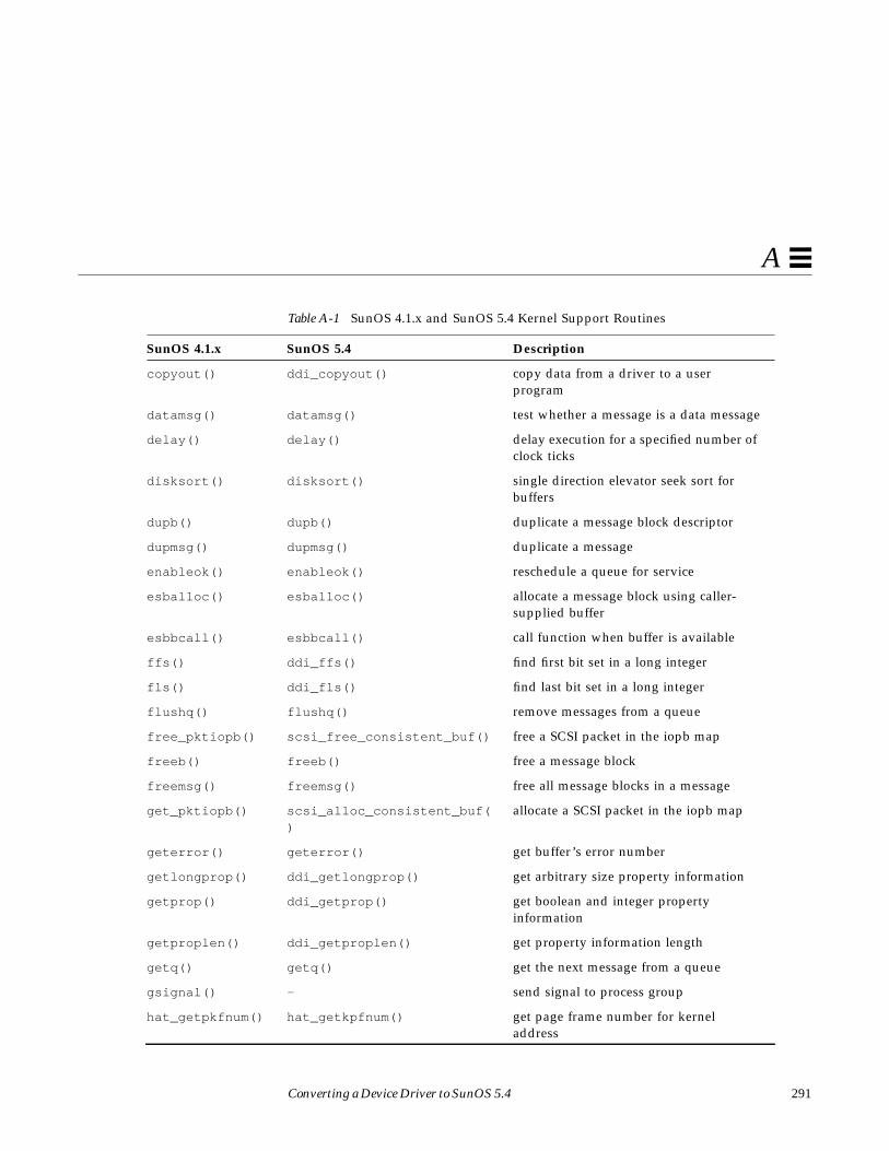
Converting a Device Driver to SunOS 5.4 291
A
copyout() ddi_copyout() copy data from a driver to a userprogram
datamsg() datamsg() test whether a message is a data message
delay() delay() delay execution for a specified number ofclock ticks
disksort() disksort() single direction elevator seek sort forbuffers
dupb() dupb() duplicate a message block descriptor
dupmsg() dupmsg() duplicate a message
enableok() enableok() reschedule a queue for service
esballoc() esballoc() allocate a message block using caller-supplied buffer
esbbcall() esbbcall() call function when buffer is available
ffs() ddi_ffs() find first bit set in a long integer
fls() ddi_fls() find last bit set in a long integer
flushq() flushq() remove messages from a queue
free_pktiopb() scsi_free_consistent_buf() free a SCSI packet in the iopb map
freeb() freeb() free a message block
freemsg() freemsg() free all message blocks in a message
get_pktiopb() scsi_alloc_consistent_buf()
allocate a SCSI packet in the iopb map
geterror() geterror() get buffer’s error number
getlongprop() ddi_getlongprop() get arbitrary size property information
getprop() ddi_getprop() get boolean and integer propertyinformation
getproplen() ddi_getproplen() get property information length
getq() getq() get the next message from a queue
gsignal() - send signal to process group
hat_getpkfnum() hat_getkpfnum() get page frame number for kerneladdress
Table A-1 SunOS 4.1.x and SunOS 5.4 Kernel Support Routines
SunOS 4.1.x SunOS 5.4 Description

292 Writing Device Drivers—August, 1994
A
index() strchr() return pointer to first occurrence ofcharacter in string
insq() insq() insert a message into a queue
kmem_alloc() kmem_alloc() allocate space from kernel free memory
kmem_free() kmem_free() free previously allocated kernel memory
kmem_zalloc() kmem_zalloc() allocate and clear space from kernel freememory
linkb() linkb() concatenate two message blocks
log() strlog() log kernel errors
machineid() - get host ID from EPROM
major() getmajor() get major device number
makecom_g0() makecom_g0() make packet for SCSI group 0 commands
makecom_g0_s() makecom_g0_s() make packet for SCSI group 0 sequentialcommands
makecom_g1() makecom_g1() make packet for SCSI group 1 commands
makecom_g5() makecom_g5() make packet for SCSI group 5 commands
mapin()map_regs()
ddi_map_regs() map physical to virtual space
mapout()unmap_regs()
ddi_unmap_regs() remove physical to virtual mappings
max() max() return the larger of two integers
mb_mapalloc() ddi_dma_buf_setup() setup system DMA resources
mb_mapfree() ddi_dma_free() release system DMA resources
mballoc() - allocate a main bus buffer
mbrelse() - free main bus resources
mbsetup() - set up use of main bus resources
min() min() return the lesser of two integers
minor() getminor() get minor device number
Table A-1 SunOS 4.1.x and SunOS 5.4 Kernel Support Routines
SunOS 4.1.x SunOS 5.4 Description

Converting a Device Driver to SunOS 5.4 293
A
minphys() minphys() limit transfer request size to systemmaximum
mp_nbmapalloc() ddi_dma_addr_setup() setup system DMA resources
MBI_ADDR() ddi_dma_htoc() retrieve DMA address
msgdsize() msgdsize() return the number of bytes in a message
nodev() nodev() error function returning ENXIO
noenable() noenable() prevent a queue from being scheduled
nulldev() nulldev() function returning zero
ovbcopy() - copy overlapping byte memory regions
panic() cmn_err() reboot at fatal error
peek() ddi_peeks() read a short value from a location
peekc() ddi_peekc() read a byte value from a location
peekl() ddi_peekl() read a long value from a location
physio() physio() limit transfer request size
pkt_transport() scsi_transport() request by a SCSI target driver to start acommand
poke() ddi_pokes() write a short value to a location
pokec() ddi_pokec() write a byte value to a location
pokel() ddi_pokel() write a long value to a location
printf() cmn_err() display an error message or panic thesystem
pritospl() - convert priority level
psignal() - send a signal to a process
ptob() ptob()ddi_ptob()
convert size in pages to size in bytes
pullupmsg() pullupmsg() concatenate bytes in a message
put() put() call a STREAMS put procedure
putbq() putbq() place a message at the head of a queue
putctl() putctl() send a control message to a queue
Table A-1 SunOS 4.1.x and SunOS 5.4 Kernel Support Routines
SunOS 4.1.x SunOS 5.4 Description
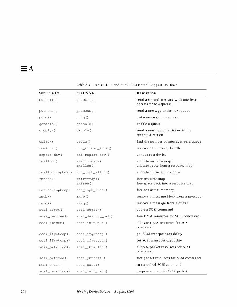
294 Writing Device Drivers—August, 1994
A
putctl1() putctl1() send a control message with one-byteparameter to a queue
putnext() putnext() send a message to the next queue
putq() putq() put a message on a queue
qenable() qenable() enable a queue
qreply() qreply() send a message on a stream in thereverse direction
qsize() qsize() find the number of messages on a queue
remintr() ddi_remove_intr() remove an interrupt handler
report_dev() ddi_report_dev() announce a device
rmalloc() rmallocmap()rmalloc()
allocate resource mapallocate space from a resource map
rmalloc(iopbmap) ddi_iopb_alloc() allocate consistent memory
rmfree() rmfreemap()rmfree()
free resource mapfree space back into a resource map
rmfree(iopbmap) ddi_iopb_free() free consistent memory
rmvb() rmvb() remove a message block from a message
rmvq() rmvq() remove a message from a queue
scsi_abort() scsi_abort() abort a SCSI command
scsi_dmafree() scsi_destroy_pkt() free DMA resources for SCSI command
scsi_dmaget() scsi_init_pkt() allocate DMA resources for SCSIcommand
scsi_ifgetcap() scsi_ifgetcap() get SCSI transport capability
scsi_ifsetcap() scsi_ifsetcap() set SCSI transport capability
scsi_pktalloc() scsi_pktalloc() allocate packet resources for SCSIcommand
scsi_pktfree() scsi_pktfree() free packet resources for SCSI command
scsi_poll() scsi_poll() run a polled SCSI command
scsi_resalloc() scsi_init_pkt() prepare a complete SCSI packet
Table A-1 SunOS 4.1.x and SunOS 5.4 Kernel Support Routines
SunOS 4.1.x SunOS 5.4 Description
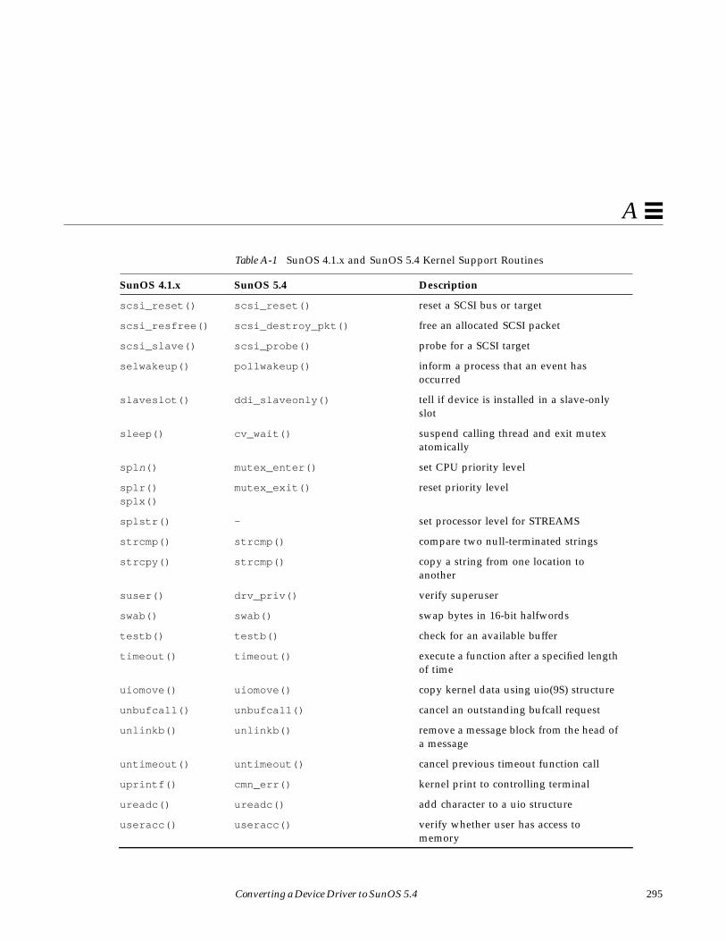
Converting a Device Driver to SunOS 5.4 295
A
scsi_reset() scsi_reset() reset a SCSI bus or target
scsi_resfree() scsi_destroy_pkt() free an allocated SCSI packet
scsi_slave() scsi_probe() probe for a SCSI target
selwakeup() pollwakeup() inform a process that an event hasoccurred
slaveslot() ddi_slaveonly() tell if device is installed in a slave-onlyslot
sleep() cv_wait() suspend calling thread and exit mutexatomically
spl n() mutex_enter() set CPU priority level
splr()splx()
mutex_exit() reset priority level
splstr() - set processor level for STREAMS
strcmp() strcmp() compare two null-terminated strings
strcpy() strcmp() copy a string from one location toanother
suser() drv_priv() verify superuser
swab() swab() swap bytes in 16-bit halfwords
testb() testb() check for an available buffer
timeout() timeout() execute a function after a specified lengthof time
uiomove() uiomove() copy kernel data using uio(9S) structure
unbufcall() unbufcall() cancel an outstanding bufcall request
unlinkb() unlinkb() remove a message block from the head ofa message
untimeout() untimeout() cancel previous timeout function call
uprintf() cmn_err() kernel print to controlling terminal
ureadc() ureadc() add character to a uio structure
useracc() useracc() verify whether user has access tomemory
Table A-1 SunOS 4.1.x and SunOS 5.4 Kernel Support Routines
SunOS 4.1.x SunOS 5.4 Description

296 Writing Device Drivers—August, 1994
A
usleep() drv_usecwait busy-wait for specified interval
uwritec() uwritec() remove a character from a uio structure
wakeup() cv_broadcast() signal condition and wake all blockedthreads
Table A-1 SunOS 4.1.x and SunOS 5.4 Kernel Support Routines
SunOS 4.1.x SunOS 5.4 Description

297
Advanced Topics B
This appendix contains a collection of topics. Not all drivers need to beconcerned with the issues addressed.
MultithreadingThis section supplements the guidelines presented in Chapter 4,“Multithreading,” for writing an MT-safe driver, a driver that safely supportsmultiple threads.
Lock Granularity
Here are some issues to consider when deciding on how many locks to use in adriver:
• The driver should allow as many threads as possible into the driver: thisleads to fine-grained locking.
• However, it should not spend too much time executing the lockingprimitives: this approach leads to coarse-grained locking.
• Moreover, the code should be simple and maintainable.• Avoid lock contention for shared data.• Write reentrant code wherever possible. This makes it possible for many
threads to execute without grabbing any locks.• Use locks to protect the data and not the code path.

298 Writing Device Drivers—August, 1994
B
• Keep in mind the level of concurrency provided by the device: if thecontroller can only handle one request at a time, there is no point inspending a lot of time making the driver handle multiple threads.
A little thought in reorganizing the ordering and types of locks around suchdata can lead to considerable savings.
Avoiding Unnecessary Locks• Use the MT semantics of the entry points to your advantage.
If an element of a device’s state structure is read-mostly—for example,initialized in attach ( ), and destroyed in detach ( ), but only read in otherentry points—there is no need to acquire a mutex to read that element of thestructure. This may sound obvious, but blindly adding calls tomutex_enter (9F) and mutex_exit (9F) around every access to such avariable can lead to unnecessary locking overhead.
• Make all entry points reentrant and reduce the amount of shared data, bychanging static variables to automatic, or by adding them to your statestructure.
Note – Kernel-thread stacks are small (currently 8 Kbytes), so do not allocatelarge automatic variables and avoid deep recursion.
Locking Order
When acquiring multiple mutexes, be sure to acquire them in the same orderon each code path. For example, mutexes A and B are used to protect tworesources in the following ways:
Code Path 1 Code Path 2
mutex_enter(&A); mutex_enter(&B);... ...
mutex_enter(&B); mutex_enter(&A);... ...
mutex_exit(&B); mutex_exit(&A);... ...
mutex_exit(&A); mutex_exit(&B);

Advanced Topics 299
B
If thread 1 is executing code path one, and thread two is executing code path 2,the following could occur:
1. Thread one acquires mutex A.
2. Thread two acquires mutex B.
3. Thread one needs mutex B, so it blocks holding mutex A.
4. Thread two needs mutex A, so it blocks holding mutex B.
These threads are now deadlocked. This is hard to track down, and usuallyeven more so since the code paths are rarely so straightforward. Also, itdoesn’t always happen, as it depends on the relative timing of threads one andtwo.
Scope of a Lock
Experience has shown that it is easier to deal with locks that are either heldthroughout the execution of a routine, or locks that are both acquired andreleased in one routine. Avoid nesting like this:
static voidxxfoo(...){
mutex_enter(&softc->lock);...xxbar();
}
static voidxxbar(...){
...mutex_exit(&softc->lock);
}
This example works, but will almost certainly lead to maintenance problems.
If contention is likely in a particular code path, try to hold locks for a shorttime. In particular, arrange to drop locks before calling kernel routines thatmight block. For example:
mutex_enter(&softc->lock);...softc->foo = bar;

300 Writing Device Drivers—August, 1994
B
softc->thingp = kmem_alloc(sizeof(thing_t), KM_SLEEP);...mutex_exit(&softc->lock);
This is better coded as:
thingp = kmem_alloc(sizeof(thing_t), KM_SLEEP);mutex_enter(&softc->lock);...softc->foo = bar;softc->thingp = thingp;...mutex_exit(&softc->lock);
Potential Panics
Here is a set of mutex-related panics:
panic: recursive mutex_enter. mutex %x caller %x
Mutexes are not reentrant by the same thread. If you already own themutex, you cannot own it again. Doing this leads to the above panic.
panic: mutex_adaptive_exit: mutex not held by thread
Releasing a mutex that the current thread does not hold causes the abovepanic.
panic: lock_set: lock held and only one CPU
This only occurs on a uniprocessor, and says that a spin mutex is held and itwould spin forever, because there is no other CPU to release it. This couldhappen because the driver forgot to release the mutex on one code path, orblocked while holding it.
A common cause of this panic is that the device’s interrupt is high-level (seeddi_intr_hilevel (9F) and Intro (9F)), and is calling a routine thatblocks the interrupt handler while holding a spin mutex. This is obvious ifthe driver explicitly calls cv_wait (9F), but may not be so if it’s blockingwhile grabbing an adaptive mutex with mutex_enter (9F).
Note – In principle, this is only a problem for drivers that operate above locklevel.

Advanced Topics 301
B
Sun Disk Device DriversSun disk devices represent an important class of block device drivers. A Sundisk device is one that is supported by disk utility commands such asformat (1M) and newfs (1M).
Disk I/O Controls
Sun disk drivers need to support a minimum set of I/O controls specific to Sundisk drivers. These I/O controls are specified in the dkio (7) manual page. DiskI/O controls transfer disk information to or from the device driver. In the casewhere data is copied out of the driver to the user, ddi_copyout (9F) should beused to copy the information into the user’s address space. When data iscopied to the disk from the user, the ddi_copyin (9F) should be used to copydata into the kernels address space. Table B-1 lists the mandatory Sun disk I/Ocontrols.
Sun disks may also support a number of optional ioctls listed in the hdio (7)manual page. Table B-2 lists optional Sun disk ioctls:
Table B-1 Mandatory Sun Disk I/O Controls
I/O Control Description
DKIOCINFO Return information describing the disk controller.
DKIOCGAPART Return a disk’s partition map.
DKIOCSAPART Set a disk’s partition map.
DKIOCGGEOM Return a disk’s geometry.
DKIOCSGEOM Set a disk’s geometry.
DKIOCGVTOC Return a disk’s Volume Table of Contents.
DKIOCSVTOC Set a disk’s Volume Table of Contents.
Table B-2 Optional Sun Disk Ioctls
I/O Control Description
HDKIOCGTYPE Return the disk’s type.
HDKIOCSTYPE Set the disk’s type.

302 Writing Device Drivers—August, 1994
B
Disk Performance
The Solaris 2.x DDI/DKI provides facilities to optimize I/O transfers forimproved file system performance. It supports a mechanism to manage the listof I/O requests so as to optimize disk access for a file system. See“Asynchronous Data Transfers” on page 184 for a description of enqueuing anI/O request.
The diskhd structure is used to manage a linked list of I/O requests.
struct diskhd {long b_flags; /* not used, needed for */
/* consistency */struct buf *b_forw, *b_back; /* queue of unit queues */struct buf *av_forw, *av_back; /* queue of bufs for this unit */long b_bcount; /* active flag */
};
The diskhd data structure has two buf pointers which can be manipulated bythe driver. The av_forw pointer points to the first active I/O request. Thesecond pointer, av_back points to the last active request on the list.
A pointer to this structure is passed as an argument to disksort (9F) alongwith a pointer to the current buf structure being processed. The disksort (9F)routine is used to sort the buf requests in a fashion that optimizes disk seekand then inserts the buf pointer into the diskhd list. The disksort programuses the value that is in b_resid of the buf structure as a sort key. It is up tothe driver to set this value. Most Sun disk drivers use the cylinder group as thesort key. This tends to optimize the file system read-ahead accesses.
Once data has been added to the diskhd list, the device needs to transfer thedata. If the device is not busy processing a request, the xxstart ( ) routinepulls the first buf structure off the diskhd list and starts a transfer.
HDKIOCGBAD Return the bad sector map of the device.
HDKIOCSBAD Set the bad sector map for the device.
HDKIOCGDIAG Return the diagnostic information regarding the most recentcommand.
Table B-2 Optional Sun Disk Ioctls
I/O Control Description
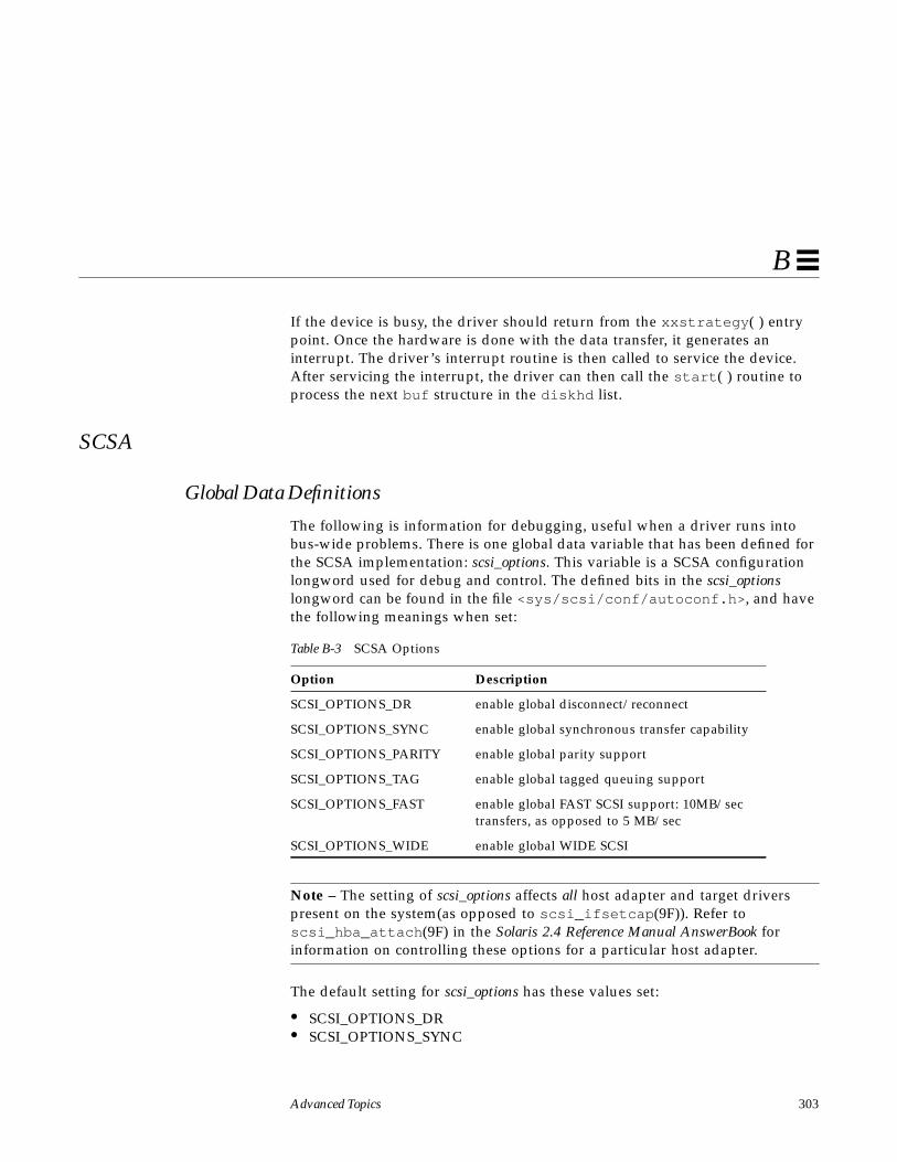
Advanced Topics 303
B
If the device is busy, the driver should return from the xxstrategy ( ) entrypoint. Once the hardware is done with the data transfer, it generates aninterrupt. The driver’s interrupt routine is then called to service the device.After servicing the interrupt, the driver can then call the start ( ) routine toprocess the next buf structure in the diskhd list.
SCSA
Global Data Definitions
The following is information for debugging, useful when a driver runs intobus-wide problems. There is one global data variable that has been defined forthe SCSA implementation: scsi_options. This variable is a SCSA configurationlongword used for debug and control. The defined bits in the scsi_optionslongword can be found in the file <sys/scsi/conf/autoconf.h> , and havethe following meanings when set:
Note – The setting of scsi_options affects all host adapter and target driverspresent on the system(as opposed to scsi_ifsetcap (9F)). Refer toscsi_hba_attach (9F) in the Solaris 2.4 Reference Manual AnswerBook forinformation on controlling these options for a particular host adapter.
The default setting for scsi_options has these values set:
• SCSI_OPTIONS_DR• SCSI_OPTIONS_SYNC
Table B-3 SCSA Options
Option Description
SCSI_OPTIONS_DR enable global disconnect/reconnect
SCSI_OPTIONS_SYNC enable global synchronous transfer capability
SCSI_OPTIONS_PARITY enable global parity support
SCSI_OPTIONS_TAG enable global tagged queuing support
SCSI_OPTIONS_FAST enable global FAST SCSI support: 10MB/sectransfers, as opposed to 5 MB/sec
SCSI_OPTIONS_WIDE enable global WIDE SCSI

304 Writing Device Drivers—August, 1994
B
• SCSI_OPTIONS_PARITY• SCSI_OPTIONS_TAG• SCSI_OPTIONS_FAST• SCSI_OPTIONS_WIDE
Tagged Queueing
For a definition of tagged queueing refer to the SCSI-2 specification. To supporttagged queueing, first check the scsi_options flag SCSI_OPTIONS_TAG to see iftagged queueing is enabled globally. Next, check to see if the target is a SCSI-2device and whether it has tagged queueing enabled. If this is all true, attemptto enable tagged queueing by using scsi_ifsetcap (9F). Code Example B-1shows an example of supporting tagged queueing.
Code Example B-1 Supporting SCSI Tagged Queueing
#define ROUTE &sdp->sd_address
...
/* * If SCSI-2 tagged queueing is supported by the disk drive and * by the host adapter then we will enable it. */
xsp->tagflags = 0;if ((scsi_options & SCSI_OPTIONS_TAG) &&
(devp->sd_inq->inq_rdf == RDF_SCSI2) &&(devp->sd_inq->inq_cmdque)) {if (scsi_ifsetcap(ROUTE, “tagged-qing”, 1, 1) == 1) {
xsp->tagflags = FLAG_STAG;xsp->throttle = 256;
} else if (scsi_ifgetcap(ROUTE, “untagged-qing”, 0) == 1) {xsp->dp->options |= XX_QUEUEING;xsp->throttle = 3;
} else {xsp->dp->options &= ~XX_QUEUEING;xsp->throttle = 1;
}}
Advanced Topics 305
B
Untagged Queueing
If tagged queueing fails, you can attempt to set untagged queuing. In thismode, you submit as many commands as you think necessary/optimal to thehost adapter driver. Then, the host adapter queues the commands to the targetone at a time (as opposed to tagged queueing, where the host adapter submitsas many commands as it can until the target indicates that the is queue full).
Auto-Request-Sense Mode
Auto-request-sense mode is most desirable if tagged or untagged queueing isused.A contingent allegiance condition is cleared by any subsequent commandand, consequently, the sense data is lost. Most HBA drivers will start the nextcommand before performing the target driver callback. However, some HBAdrivers may use a separate and lower priority thread to perform the callbacks,which may increase the time it takes to notify the target driver that the packetcompleted with a check condition. In this cas, the target driver may not be ableto submit a request sense command in time to retrieve the sense data.
To avoid this loss of sense data, the HBA driver, or controller, should issue arequest sense command as soon as a check condition has been detected; thismode is known as auto-request_sense mode. Note that not all HBA drivers arecapable of auto-request-sense mode, and some can only operate with auto-request-sense mode enabled.
A target driver enables auto-request-sense mode by usingscsi_ifsetcap (9F). Code Example B-2 is an example of enabling autorequest sense.
Code Example B-2 Enabling auto request sense
static intxxattach(dev_info_t *dip, ddi_attach_cmd_t cmd){
struct xxstate *xsp;struct scsi_device *sdp = (struct scsi_device *) ddi_get_driver_private(dip);
...
/*
306 Writing Device Drivers—August, 1994
B
* enable auto-request-sense; an auto-request-sense cmd may fail * due to a BUSY condition or transport error. Therefore, it is * recommended to allocate a separate request sense packet as * well. * Note that scsi_ifsetcap(9F) may return -1, 0, or 1 */
xsp->sdp_arq_enabled = ((scsi_ifsetcap(ROUTE, “auto-rqsense”, 1, 1) == 1) ? 1 : 0);
/* * if the HBA driver supports auto request sense then the * status blocks should be sizeof (struct scsi_arq_status); else * one byte is sufficient */xsp->sdp_cmd_stat_size = (xsp->sdp_arq_enabled ? sizeof (struct scsi_arq_status) : 1);...
}
When a packet is allocated using scsi_init_pkt (9F) and auto request senseis desired on this packet then the target driver must request additional spacefor the status block to hold the auto request sense structure (asCode Example B-3 illustrates). The sense length used in the request sensecommand is sizeof (struct scsi_extended_sense).
The scsi_arq_status structure contains the following members:
struct scsi_status sts_status;struct scsi_status sts_rqpkt_status;u_char sts_rqpkt_reason;/* reason completion */u_char sts_rqpkt_resid;/* residue */u_long sts_rqpkt_state;/* state of command */u_long sts_rqpkt_statistics;/* statistics */struct scsi_extended_sense sts_sensedata;
Auto request sense can be disabled per individual packet by just allocatingsizeof (struct scsi_status) for the status block.
Code Example B-3 Allocating a packet with auto request sense
pkt = scsi_init_pkt(ROUTE, NULL, bp, CDB_GROUP1, xsp->sdp_cmd_stat_size, PP_LEN, 0, func, (caddr_t) xsp);
The packet is submitted using scsi_transport (9F) as usual. When a checkcondition occurs on this packet, the host adapter driver:

Advanced Topics 307
B
• Issues a request sense command if the controller doesn’t have auto-request-sense capability.
• Obtains the sense data
• Fills in the scsi_arq_status information in the packet’s status block
• Sets STATE_ARQ_DONE in the packet’s pkt_state field.
• Calls the packet’s callback handler (pkt_comp)
The target driver’s callback routine should verify that sense data is availableby checking the STATE_ARQ_DONE bit in pkt_state which implies that acheck condition has occurred and a request sense has been performed. If auto-request-sense has been temporarily disabled in a packet, there is no guaranteethat the sense data can be retrieved at a later time.
The target driver should then verify whether the auto request sense commandcompleted successfully and decode the sense data.
Code Example B-4 Checking for auto request sense
static voidxxcallback(struct scsi_pkt *pkt){
...
if (pkt->pkt_state & STATE_ARQ_DONE) {/* * The transport layer successfully completed an * auto-request-sense. * Decode the auto request sense data here */....
}...
}
The sample SCSI drivers in appendixes E and F show in more detail how tointerpret the auto request sense data structure.

308 Writing Device Drivers—August, 1994
B
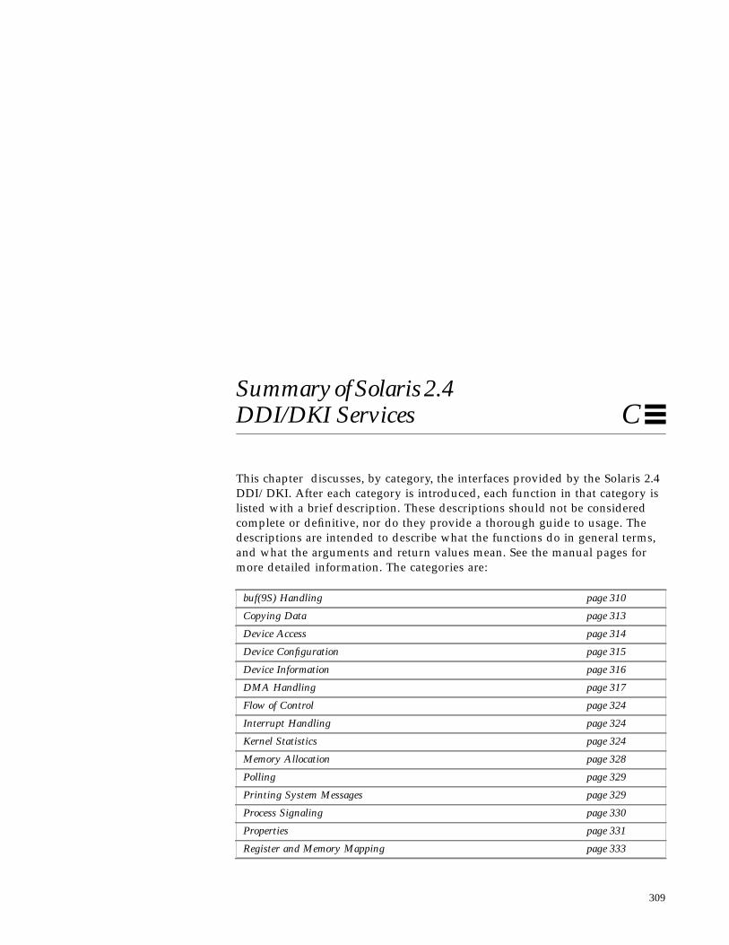
309
Summary of Solaris 2.4DDI/DKI Services C
This chapter discusses, by category, the interfaces provided by the Solaris 2.4DDI/DKI. After each category is introduced, each function in that category islisted with a brief description. These descriptions should not be consideredcomplete or definitive, nor do they provide a thorough guide to usage. Thedescriptions are intended to describe what the functions do in general terms,and what the arguments and return values mean. See the manual pages formore detailed information. The categories are:
buf(9S) Handling page 310
Copying Data page 313
Device Access page 314
Device Configuration page 315
Device Information page 316
DMA Handling page 317
Flow of Control page 324
Interrupt Handling page 324
Kernel Statistics page 324
Memory Allocation page 328
Polling page 329
Printing System Messages page 329
Process Signaling page 330
Properties page 331
Register and Memory Mapping page 333

310 Writing Device Drivers—August, 1994
C
STREAMS interfaces are not discussed here; to learn about them, see theSTREAMS Programmer’s Guide.
buf (9S) HandlingThese interfaces manipulate the buf (9S) data structure. It is used to encodeblock I/O transfer requests, but some character drivers also use buf (9S) toencode character I/O requests with physio (9F). Drivers that use buf (9S) astheir primary means of encoding I/O requests have to implement astrategy (9E) routine. See Chapter 9, “Drivers for Block Devices,” andChapter 8, “Drivers for Character Devices” for more information.
void biodone(struct buf *bp);
biodone (9F) marks the I/O described by the buf (9S) structure pointed to bybp as complete by setting the B_DONE flag in bp->b_flags . biodone (9F)then notifies any threads waiting in biowait (9F) for this buffer. Callbiodone (9F) on bp when the I/O request it encodes is finished.
void bioerror(struct buf *bp, int error);
bioerror(9F) marks the error bits in the I/O described by the buf(9S)structure pointed to by bp with error .
I/O Port Access page 333
SCSI and SCSA page 336
Soft State Management page 341
String Manipulation page 344
System Information page 346
Thread Synchronization page 346
Timing page 351
uio(9S) Handling page 352
Utility Functions page 352
Summary of Solaris 2.4 DDI/DKI Services 311
C
void bioreset(struct buf *bp);
bioreset(9F) is used to reset the buf(9S) structure pointed to by bpallowing a device driver to reuse privately allocated buffers. bioreset(9F)resets the buffer header to its initially allocated state.
int biowait(struct buf *bp);
biowait (9F) suspends the calling thread until the I/O request described by bpcompletes. A call to biodone (9F) unblocks the waiting thread. Usually, if adriver does synchronous I/O, it calls biowait (9F) in its strategy (9E)routine, and calls biodone (9F) in its interrupt handler when the request iscomplete.
biowait (9F) is usually not called by the driver, instead it is called byphysio (9F), or by the file system after calling strategy (9F). The driver isresponsible for calling biodone (9F) when the I/O request is complete.
void bp_mapin(struct buf *bp);
bp_mapin (9F) maps the data buffer associated with the buf (9S) structurepointed to by bp into the kernel virtual address space so the driver can accessit. Programmed I/O device drivers often use bp_mapin (9F) because they haveto transfer data explicitly between the buf (9S) structure’s buffer and a devicebuffer. See “bp_mapin( )” on page 177 for more information.
void bp_mapout(struct buf *bp);
bp_mapout (9F) unmaps the data buffer associated with the buf (9S) structurepointed to by bp . The buffer must have been mapped previously bybp_mapin (9F). bp_mapout (9F) can only be called from user or kernel context.
void clrbuf(struct buf *bp);
clrbuf (9F) zeroes bp->b_bcount bytes starting at bp->b_un.b_addr .
312 Writing Device Drivers—August, 1994
C
void disksort(struct diskhd *dp, struct buf *bp);
disksort (9F) implements a queueing strategy for block I/O requests to block-oriented devices. dp is a pointer to a diskhd structure that represents the headof the request queue for a the disk. disksort (9F) sorts bp into this queue inascending order of cylinder number. The cylinder number is stored in theb_resid field of the buf(9S) structure. This strategy minimizes seek time forsome disks.
void freerbuf(struct buf *bp);
freerbuf (9F) frees the buf (9S) structure pointed to by bp . The structure musthave been allocated previously by getrbuf (9F).
int geterror(struct buf *bp);
geterror (9F) returns the error code stored in bp if the B_ERROR flag is set inbp->b_flags . It returns zero if no error occurred.
struct buf *getrbuf(long sleepflag);
getrbuf (9F) allocates a buf (9S) structure and returns a pointer to it.sleepflag should be either KM_SLEEP or KM_NOSLEEP, depending onwhether getrbuf (9F) should wait for a buf (9S) structure to become availableif one cannot be allocated immediately.
int physio( int (*strat)(struct buf *), struct buf *bp,dev_t dev, int rw, void (*mincnt)(struct buf *),struct uio *uio);
physio (9F) translates a read or write I/O request encoded in a uio (9S)structure into a buf (9S) I/O request. strat is a pointer to a strategy (9E)routine which physio (9F) calls to handle the I/O request. If bp is NULL,physio(9F) allocates a private buf (9S) structure.
Before calling strategy(9E), physio (9F) locks down the memory referred to bythe buf(9S) structure (initialized from the uio (9S) structure). For this reason,many drivers which do DMA must use physio (9F) as it is the only way to lockdown memory.
Summary of Solaris 2.4 DDI/DKI Services 313
C
In most block device drivers, read (9E) and write (9E) handle raw I/Orequests, and consist of little more than a call to physio (9F).
void minphys(struct buf *bp);
minphys (9F) can be passed as the mincnt argument to physio (9F). Thiscauses physio (9F) to make I/O requests to the strategy routine that are nolarger than the system default maximum data transfer size. If the originaluio (9S) I/O request is to transfer a greater amount of data than minphys (9F)allows, physio (9F) calls strategy (9E) repeatedly.
Copying DataThese interfaces are data copying utilities, used both for copying data withinthe kernel, and for copying data between the kernel and an applicationprogram.
void bcopy(caddr_t from, caddr_t to, size_t bcount);
bcopy (9F) copies count bytes from the location pointed to by from to thelocation pointed to by to .
int copyin(caddr_t userbuf, caddr_t driverbuf,size_t cn);
copyin (9F) copies data from an application program’s virtual address space tothe kernel virtual address space, where the driver can address the data. Thedriver developer must ensure that adequate space is allocated for driverbuf .
int copyout(caddr_t driverbuf, caddr_t userbuf,size_t cn);
copyout (9F) copies data from the kernel virtual address space to anapplication program’s virtual address space.

314 Writing Device Drivers—August, 1994
C
int ddi_copyin(caddr_t buf, caddr_t driverbuf,size_t cn, int flags);
This routine is designed for use in driver ioctl (9E) routines. It copies datafrom a source address to a driver buffer. The driver developer must ensure thatadequate space is allocated for the destination address.
The flags argument is used to determine the address space information aboutbuf . If the FKIOCTL flag is set, it indicates that buf is a kernel address, andddi_copyin (9F) behaves like bcopy (9F). Otherwise buf is interpreted as auser buffer address, and ddi_copyin (9F) behaves like copyin (9F).
The value of the flags argument to ddi_copyin (9F) should be passedthrough directly from the mode argument of ioctl (9E) untranslated.
int ddi_copyout(caddr_t driverbuf, caddr_t buf,size_t cn, int flags);
This routine is designed for use in driver ioctl (9E) routines for drivers thatsupport layered I/O controls. ddi_copy out (9F) copies data from a driverbuffer to a destination address, buf .
The flags argument is used to determine the address space information aboutbuf . If the FKIOCTL flag is set, it indicates that buf is a kernel address, andddi_copy out (9F) behaves like bcopy (9F). Otherwise buf is interpreted as auser buffer address, and ddi_copyin (9F) behaves like copy out(9F).
The value of the flags argument to ddi_copy out(9F) should be passedthrough directly from the mode argument of ioctl (9E) untranslated.
Device AccessThese interfaces verify the credentials of application threads making systemcalls into drivers. They are sometimes used in the open (9E) entry point torestrict access to a device, though this is usually achieved with the permissionson the special files in the file system.

Summary of Solaris 2.4 DDI/DKI Services 315
C
int drv_priv(cred_t *credp);
drv_priv (9F) returns zero if the credential structure pointed to by credp isthat of a privileged thread. It returns EPERM otherwise. Only usedrv_priv (9F) in place of calls to the obsolete suser () function and whenmaking explicit checks of a calling thread’s UID.
Device ConfigurationThese interfaces are used in setting up a driver and preparing it for use. Someof these routines handle the dynamic loading of device driver modules into thekernel, and some manage the minor device nodes in /devices that are theinterface to a device for application programs. All of these routines areintended to be called in the driver’s _init (9E), _fini (9E), _info (9E),attach (9E), detach (9E), and probe (9E) entry points.
int ddi_create_minor_node(dev_info_t *dip, char *name,int spec_type, int minor_num, char *node_type,int is_clone);
ddi_create_minor_node (9F) advertises a minor device node, which willeventually appear in the /devices directory and refer to the device specifiedby dip .
void ddi_remove_minor_node(dev_info_t *dip,char *name);
ddi_remove_minor_node (9F) removes the minor device node name for thedevice dip from the system. name is assumed to have been created byddi_create_minor_node (9F). If name is NULL, all minor node information isremoved.
int mod_install(struct modlinkage *modlinkage);
mod_install (9F) links the calling driver module into the system and preparesthe driver to be used. modlinkage is a pointer to the modlinkage structuredefined in the driver. mod_install (9F) must be called from the _init (9E)entry point.
316 Writing Device Drivers—August, 1994
C
int mod_remove(struct modlinkage *modlinkage);
mod_remove (9F) unlinks the calling driver module from the system.modlinkage is a pointer to the modlinkage structure defined in the driver.mod_remove (9F) must be called from the _fini (9E) entry point.
int mod_info(struct modlinkage *modlinkage,struct modinfo *modinfop);
mod_info (9F) reports the status of a dynamically loadable driver module. Itmust be called from the _info (9E) entry point.
Device InformationThese interfaces provide information to the driver about a device, such aswhether the device is self-identifying, what instance number the system hasassigned to a device instance, the name of the dev_info node for the device,and the dev_info node of the device’s parent.
int ddi_dev_is_sid(dev_info_t *dip);
ddi_dev_is_sid (9F) returns DDI_SUCCESS if the device identified by dip isself-identifying (see “Device Identification” on page 14). Otherwise, it returnsDDI_FAILURE .
int ddi_get_instance(dev_info_t *dip);
ddi_get_instance (9F) returns the instance number assigned by the systemfor the device instance specified by dip .
char *ddi_get_name(dev_info_t *dip);
ddi_get_name (9F) returns a pointer to a character string that is the name ofthe dev_info tree node specified by dip . ddi_get_name (9F) should becalled in the identify (9E) entry point and the result compared to the name ofthe device.

Summary of Solaris 2.4 DDI/DKI Services 317
C
dev_info_t *ddi_get_parent(dev_info_t *dip);
ddi_get_parent (9F) returns the dev_info_t pointer for the parentdev_info node of the passed node, identified by dip .
int ddi_slaveonly(dev_info_t *dip);
ddi_slaveonly (9F) returns DDI_SUCCESS if the device indicated by dip isinstalled in a slave access only bus slot. It returns DDI_FAILURE otherwise.
DMA HandlingThese interfaces allocate and release DMA resources for devices capable ofdirectly accessing system memory. The family of setup functions are allwrappers around the main setup function, ddi_dma_setup (9F). The wrappersmake it easier to allocate DMA resources for use with kernel virtual addresses(ddi_dma_addr_setup (9F)), and buf (9S) structures(ddi_dma_buf_setup (9F)). The setup functions pass back a pointer to a DMAhandle, which identifies the allocated DMA resources in future calls to otherDMA handling functions.
The DMA setup functions take a pointer to a DMA limits structure as anargument. The DMA limits structure allows any constraints which the device’sDMA controller may impose on DMA transfers to be specified, such as alimited transfer size.
The DMA setup functions also provide a callback mechanism where a functioncan be specified to be called later if the requested mapping can’t be set upimmediately.
The DMA window functions allow resources to be allocated for a large object.The resources can be moved from one part of the object to another by movingthe DMA window.
The DMA engine functions allow drivers to manipulate the system DMAengine, if there is one. These are currently used on x86 systems.

318 Writing Device Drivers—August, 1994
C
int ddi_dma_addr_setup(dev_info_t *dip,struct as *as, caddr_t addr, u_int len,u_int flags, int (*waitfp)(caddr_t),caddr_t arg, ddi_dma_lim_t *lim,ddi_dma_handle_t *handlep);
ddi_dma_addr_setup (9F) allocates resources for an object of length len atkernel address addr , subject to any constraints specified by lim . waitfp is apointer to a callback function to be called later if the DMA resources cannot beallocated right away. If the resources are allocated successfully,ddi_dma_addr_setup (9F) passes back the DMA handle for the mapping inthe location pointed to by handlep . NULL should be passed for as .
int ddi_dma_buf_setup(dev_info_t *dip, struct buf *bp,u_int flags, int (*waitfp)(caddr_t),caddr_t arg, ddi_dma_lim_t *lim,ddi_dma_handle_t *handlep);
ddi_dma_buf_setup (9F) allocates resources for an object described by abuf (9F) structure pointed to by bp , subject to constraints specified by lim .waitfp is a pointer to a callback function to be called later if the DMAresources cannot be allocated right away. If the resources are allocatedsuccessfully, ddi_dma_buf_setup (9F) passes back the DMA handle for theresources in the location pointed to by handlep .
int ddi_dma_burstsizes(ddi_dma_handle_t handle);
ddi_dma_burstsizes (9F) returns an integer that encodes the allowed burstsizes for the DMA resources specified by handle . Allowed power of two burstsizes are bit-encoded in the return value. For a mapping that allows only two-byte bursts, for example, the return value would be 0x2 . For a mapping thatallows 1, 2, 4, and 8 byte bursts, the return value would be 0xf .

Summary of Solaris 2.4 DDI/DKI Services 319
C
int ddi_dma_coff(ddi_dma_handle_t handle,ddi_dma_cookie_t *cookiep, off_t *offp);
ddi_dma_coff (9F) passes back, in the location pointed to by offp , an offsetinto a DMA object. The mapping is specified by handle , and the offset offp isderived from the DMA cookie referred to by cookiep . ddi_dma_coff (9F)can be used after a DMA transfer is complete to find out where the DMAcontroller stopped.
int ddi_dma_curwin(ddi_dma_handle_t handle,off_t *offp, u_int *lenp);
ddi_dma_curwin (9F) passes back the offset and length of the current DMAwindow in the locations pointed to by offp and lenp , respectively.
int ddi_dma_devalign(ddi_dma_handle_t handle,u_int *alignment, u_int *minxfr);
ddi_dma_devalign (9F) passes back, in the location pointed to byalignment , the required alignment for the beginning of a DMA transfer usingthe resources identified by handle . The alignment will be a power of two.ddi_dma_devalign (9F) also passes back in the location pointed to byminxfr the minimum number of bytes of the mapping that will be read orwritten in a single transfer.
int ddi_dma_htoc(ddi_dma_handle_t handle, off_t off,ddi_dma_cookie_t *cookiep);
ddi_dma_htoc (9F) passes back a DMA cookie in the location pointed to bycookiep that represents a DMA transfer starting at off in the DMA resourcesidentified by handle . The DMA cookie is described in ddi_dma_cookie (9S)that contains information about a potential DMA transfer. The fielddmac_address contains the transfer address for the DMA controller.

320 Writing Device Drivers—August, 1994
C
int ddi_dma_movwin(ddi_dma_handle_t handle,off_t *offp, u_int *lenp,ddi_dma_cookie_t *cookiep);
ddi_dma_movwin (9F) moves the current DMA window in the mappingidentified by handle . The new window offset and length are passed back inthe locations pointed to by offp and lenp , respectively. If a pointer to a DMAcookie structure is passed in cookiep , ddi_dma_movwin (9F) callsddi_dma_htoc (9F) passes back a new DMA cookie in the location pointed toby cookiep .
int ddi_dma_nextseg(ddi_dma_win_t win,ddi_dma_seg_t seg, ddi_dma_seg_t *nseg);
ddi_dma_nextseg (9F) gets the next DMA segment within the specifiedwindow win . If the current segment is NULL, the first DMA segment withinthe window is returned.
int ddi_dma_nextwin(ddi_dma_handle_t handle,ddi_dma_win_t win, ddi_dma_win_t *nwin);
ddi_dma_nextwin(9F) shifts the current DMA window win within the objectreferred to by handle to the next DMA window nwin . If the current windowis NULL, the first window within the object is returned.
int ddi_dma_segtocookie(ddi_dma_seg_t seg,off_t *offp, off_t *lenp,ddi_dma_cookie_t *cookiep);
ddi_dma_segtocookie (9F) takes a DMA segment and fills in the cookiepointed to by cookiep with the appropriate address, length, and bus type tobe used to program the DMA engine. ddi_dma_segtocookie (9F) also fills in*offp and *lenp , which specify the range within the object.

Summary of Solaris 2.4 DDI/DKI Services 321
C
int ddi_dma_setup(dev_info_t *dip,struct ddi_dma_req *dmareqp,ddi_dma_handle_t *handlep);
ddi_dma_setup (9F) is the main DMA resource allocation function. It allocatesresources based on the DMA request structure pointed to by dmareqp , andpasses back a DMA handle that identifies the mapping in the location pointedto by handlep .
int ddi_dma_free(ddi_dma_handle_t handle);
ddi_dma_free (9F) calls ddi_dma_sync (9F) and frees the resourcesassociated with the DMA mapping identified by handle .
int ddi_dma_sync(ddi_dma_handle_t handle, off_t off,u_int length, u_int type);
ddi_dma_sync (9F) assures that any CPU and the device see the same datastarting at off bytes into the DMA resources identified by handle andcontinuing for len bytes. type should be:
• DDI_DMA_SYNC_FORDEV to make sure the device sees any changes made bya CPU.
• DDI_DMA_SYNC_FORCPU to make sure all CPUs see any changes made bythe device.
• DDI_DMA_SYNC_FORKERNEL, similar to DDI_DMA_SYNC_FORCPU, exceptthat only the kernel view of the object is synchronized.
int ddi_dmae_alloc(dev_info_t *dip, int chnl,int (*dmae_waitfp)(), caddr_t arg);
ddi_dmae_alloc (9F) allocates a DMA channel from the system DMA engine.It must be called prior to any operation on a channel.
int ddi_dmae_release(dev_info_t *dip, int chnl);
ddi_dmae_release (9F) releases a previously allocated DMA channel.
322 Writing Device Drivers—August, 1994
C
int ddi_dmae_prog(dev_info_t *dip,struct ddi_dmae_req *dmaereqp,ddi_dma_cookie_t *cookiep, int chnl);
The ddi_dmae_prog (9F) function programs the DMA channel for anoperation. This function allows access to various capabilities of the DMAengine hardware. It disables the channel prior to setup, and enables thechannel before returning.
The DMA address and count are specified by passing ddi_dmae_prog (9F)a cookie obtained from ddi_dma_segtocookie (9F). Other DMA engineparameters are specified by the DMA engine request structure passed inthrough dmaereqp . The fields of that structure are documented inddi_dmae_req (9S).
int ddi_dmae_disable(dev_info_t *dip, int chnl);
The ddi_dmae_disable (9F) function disables the DMA channel so that it nolonger responds to a device’s DMA service requests.
int ddi_dmae_enable(dev_info_t *dip, int chnl);
The ddi_dmae_enable (9F) function enables the DMA channel foroperation. This may be used to re-enable the channel after a call toddi_dmae_disable (9F). The channel is automatically enabled after successfulprogramming by ddi_dmae_prog (9F).
int ddi_dmae_stop(dev_info_t *dip, int chnl);
The ddi_dmae_stop (9F) function disables the channel and terminates anyactive operation.
int ddi_dmae_getcnt(dev_info_t *dip, int chnl,int *countp);
The ddi_dmae_getcnt (9F) function examines the count register of the DMAchannel and sets (*countp ) to the number of bytes remaining to be transferred.The channel is assumed to be stopped.

Summary of Solaris 2.4 DDI/DKI Services 323
C
int ddi_dmae_1stparty(dev_info_t *dip, int chnl);
The ddi_dmae_1stparty (9F) function is used, by device drivers using first-party DMA, to configure a channel in the system’s DMA engine to operate in a‘‘slave’’ mode.
int ddi_dmae_getlim(dev_info_t *dip,ddi_dma_lim_t *limitsp);
The ddi_dmae_getlim (9F) function fills in the DMA limit structure, pointedto by limitsp , with the DMA limits of the system DMA engine. This limitstructure must be passed to the DMA setup routines so that they will knowhow to break the DMA request into windows and segments. If the device hasany particular restrictions on transfer size or granularity (for example, a disksector size), the driver should further restrict the values in the structuremembers before passing them to the DMA setup routines. The driver must notrelax any of the restrictions embodied in the structure after it is filled in byddi_dmae_getlim (9F).
int ddi_iomin(dev_info_t *dip, int initial,int streaming);
ddi_iomin (9F) returns an integer that encodes the required alignment and theminimum number of bytes that must be read or written by the DMA controllerof the device identified by dip . ddi_iomin (9F) is likeddi_dma_devalign (9F), but the memory object is assumed to be primarymemory, and the alignment is assumed to be equal to the minimum possibletransfer.
int ddi_iopb_alloc(dev_info_t *dip,ddi_dma_lim_t *limits, u_int length,caddr_t *iopbp);
ddi_iopb_alloc (9F) allocates a block of length bytes of memory, subject toconstraints specified by limits . A block of memory so allocated is commonlycalled an “I/O parameter block”, or IOPB, and is usually used to encode adevice command. This block of consistent memory can be directly accessed bythe device. A pointer to the allocated IOPB is passed back in the locationpointed to by iopbp .

324 Writing Device Drivers—August, 1994
C
void ddi_iopb_free(caddr_t iopb);
ddi_iopb_free (9F) frees the I/O parameter block pointed to by iopb , whichmust have been allocated previously by ddi_iopb_alloc (9F).
Flow of ControlThese interfaces influence the flow of program control in a driver. These aremostly callback mechanisms, functions that schedule another function to run ata later time. Many drivers schedule a function to run every so often to check onthe status of the device, and possibly issue an error message if some strangecondition is detected.
Note – The detach (9E) entry point must assure that no callback functions arepending in the driver before returning successfully. See Chapter 5,“Autoconfiguration.”
int timeout(void (*ftn)(caddr_t), caddr_t arg,long ticks);
timeout (9F) schedules the function pointed to by ftn to be run after ticksclock ticks have elapsed. arg is passed to the function when it is run.timeout (9F) returns a “timeout ID” that can be used to cancel the timeoutlater.
int untimeout(int id);
untimeout (9F) cancels the timeout indicated by the timeout ID id . If thenumber of clock ticks originally specified to timeout (9F) have not elapsed, thecallback function will not be called.
Interrupt HandlingThese interfaces manage device interrupts and software interrupts. The basicmodel is to register with the system an interrupt handling function to be calledwhen a device interrupts or a software interrupt is triggered.

Summary of Solaris 2.4 DDI/DKI Services 325
C
int ddi_add_intr(dev_info_t *dip, u_int inumber,ddi_iblock_cookie_t *iblock_cookiep,ddi_idevice_cookie_t *idevice_cookiep,u_int (*int_handler)(caddr_t),caddr_t int_handler_arg);
ddi_add_intr (9F) tells the system to call the function pointed to byint_handler when the device specified by dip issues the interrupt identifiedby inumber . ddi_add_intr (9F) passes back an interrupt block cookie in thelocation pointed to by iblock_cookiep , and an interrupt device cookie inthe location pointed to by idevice_cookiep . The interrupt block cookie isused to initialize mutual exclusion locks (mutexes) and other synchronizationvariables. The device interrupt cookie is used to program the level at which thedevice interrupts, for those devices that support such programming.
void ddi_remove_intr(dev_info_t *dip, u_int inumber,ddi_iblock_cookie_t iblock_cookie);
ddi_remove_intr (9F) tells the system to stop calling the interrupt handlerregistered for the interrupt inumber on the device identified by dip .iblock_cookie is the interrupt block cookie that was returned byddi_add_intr (9F) when the interrupt handler was set up. Device interruptsmust be disabled before calling ddi_remove_intr (9F), and always callddi_remove_intr (9F) in the detach (9E) entry point before returningsuccessfully (if any interrupts handlers were added).
int ddi_add_softintr(dev_info_t *dip, int preference,ddi_softintr_t *idp, ddi_iblock_cookie_t *ibcp,ddi_idevice_cookie_t *idcp,u_int (*int_handler)(caddr_t),caddr_t int_handler_arg);
ddi_add_softintr (9F) tells the system to call the function pointed to byint_handler when a certain software interrupt is triggered.ddi_add_softintr (9F) returns a software interrupt ID in the locationpointed to by idp . This ID is later used by ddi_trigger_softintr (9F) totrigger the software interrupt.

326 Writing Device Drivers—August, 1994
C
void ddi_trigger_softintr(ddi_softintr_t id);
ddi_trigger_softintr (9F) triggers the software interrupt identified by id .The interrupt handling function that was set up for this software interrupt byddi_add_softintr (9F) is then called.
void ddi_remove_softintr(ddi_softintr_t id);
ddi_remove_softintr (9F) tells the system to stop calling the softwareinterrupt handler for the software interrupt identified by id . If the driver hassoft interrupts registered, it must call ddi_remove_softintr (9F) in thedetach (9E) entry point before returning successfully.
int ddi_dev_nintrs(dev_info_t *dip, int *result);
ddi_dev_nintr (9F) passes back in the location pointed to by result thenumber of different interrupt specifications that the device indicated by dipcan generate. This is useful when dealing with a device that can interrupt atmore than one level.
int ddi_intr_hilevel(dev_info_t *dip, u_int inumber);
ddi_intr_hilevel (9F) returns non-zero if the system considers the interruptspecified by inumber on the device identified by dip to be high level.Otherwise, it returns zero.
Kernel StatisticsThese interfaces allow device drivers to store statistics about the device in thekernel for later retrieval by applications.
kstat_t *kstat_create(char *module, int instance,char *name, char *class, uchar_t type,ulong_t ndata, uchar_t ks_flag);
kstat_create(9F) allocates and performs necessary system initialization ofa kstat(9S) structure. After a successful call to kstat_create(9F) thedriver must perform any necessary initialization of the data structure and thenuse kstat_install(9F) to make the kstat(9S) structure accessible touser land applications.

Summary of Solaris 2.4 DDI/DKI Services 327
C
void kstat_delete(kstat_t *ksp);
kstat_delete(9F) removes the kstat(9S) structure pointed to by kspfrom the kernel statistics data and frees associated system resources.
void kstat_install(kstat_t *ksp);
kstat_install(9F) allows the kstat(9S) structure pointed to by ksp tobe accessible by the user land applications.
void kstat_named_init(kstat_named_t *knp, char *name,uchar_t data_type);
kstat_named_init(9F) associates the name pointed to by name and thetype specified in data_type with the kstat_named(9S) structure pointedto by knp .
void kstat_waitq_enter(kstat_io_t *kiop);
kstat_waitq_enter(9F) is used to update the kernel_io(9S) structurepointed to by kiop indicating that a request has arrived but has not yet beprocessed.
void kstat_waitq_exit(kstat_io_t *kiop);
kstat_waitq_exit(9F) is used to update the kernel_io(9S) structurepointed to by kiop indicating that the request is about to be serviced.
void kstat_runq_enter(kstat_io_t *kiop);
kstat_runq_enter(9F) is used to update the kernel_io(9S) structurepointed to by kiop indicating that the request is in the process of beingserviced. kstat_runq_enter(9F) is generally invoked after a call tokstat_waitq_exit(9F) .
void kstat_runq_exit(kstat_io_t *kiop);
kstat_runq_exit(9F) is used to update the kernel_io(9S) structurepointed to by kiop indicating that the request is serviced.

328 Writing Device Drivers—August, 1994
C
void kstat_waitq_to_runq(kstat_io_t *kiop);
kstat_waitq_to_runq(9F) is used to update the kernel_io(9S) structurepointed to by kiop indicating that the request is transitioning from one state tothe next. kstat_waitq_to_runq(9F) is used when a driver would normallycall kstat_waitq_exit(9F) followed immediately bykstat_runq_enter(9F) .
void kstat_runq_to_waitq(kstat_io_t *kiop);
kstat_runq_to_waitq(9F) is used to update the kernel_io(9S) structurepointed to by kiop indicating that the request is transitioning from one state tothe next. kstat_runq_to_waitq(9F) is used when a driver would normallycall kstat_runq_exit(9F) followed immediately by a call tokstat_waitq_enter(9F) .
Memory AllocationThese interfaces dynamically allocate memory for the driver to use.
void *kmem_alloc(size_t size, int flag);
kmem_alloc (9F) allocates a block of kernel virtual memory of length size andreturns a pointer to it. If flag is KM_SLEEP, kmem_alloc (9F) may block waitingfor memory to become available. If flag is KM_NOSLEEP, kmem_alloc (9F)returns NULL if the request cannot be satisfied immediately.
void kmem_free(void *cp, size_t size);
kmem_free (9F) releases a block of memory of length size starting at addressaddr that was previously allocated by kmem_alloc (9F). size must be theoriginal amount allocated.
void *kmem_zalloc(size_t size, int flags);
kmem_zalloc (9F) calls kmem_alloc (9F) to allocate a block of memory oflength size , and calls bzero (9F) on the block to zero its contents beforereturning its address.

Summary of Solaris 2.4 DDI/DKI Services 329
C
PollingThese interfaces support the poll (2) system call, which provides a mechanismfor application programs to “poll” character-oriented devices, inquiring abouttheir readiness to perform certain I/O operations. See the poll (2) manual pagefor details.
int nochpoll(dev_t dev, short events, int anyyet,short *reventsp, struct pollhead **pollhdrp);
Use nochpoll (9F) as the chpoll entry in the cb_ops (9S) structure if thedriver does not support polling.
void pollwakeup(struct pollhead *php, short event);
If the driver does implement a chpoll (9E) entry point to support polling, itshould call pollwakeup (9F) whenever the event occurs.
Printing System MessagesThese interfaces are functions that display messages on the system console.
void cmn_err(int level, char *format, ...);
cmn_err (9F) is the mechanism for printing messages on the system console.level may be one of CE_NOTE, CE_WARN, CE_CONT, or CE_PANIC. CE_NOTEindicates a purely informational message. CE_WARN indicates a warning to theuser. CE_CONT continues a previous message. And CE_PANIC issues a fatalerror and crashes the system. Use CE_PANIC only for unrecoverable systemerrors!
Whenever possible, CE_CONT should be used to print system messages. Notethat CE_PANIC, CE_NOTE, and CE_WARN cause cmn_err (9F) to always appenda new line to the message.
void ddi_report_dev(dev_info_t *dip);
ddi_report_dev (9F) possibly prints a message announcing the presence of adevice on the system. Call this function before returning from a successfulattach (9E).

330 Writing Device Drivers—August, 1994
C
char *sprintf(char *buf, const char *fmt, ...);
sprintf (9F) is just like the C library’s sprintf (3). Use it to format a messageand place it in buf .
void vcmn_err(int level, char *format, va_list ap);
vcmn_err (9F) is a version of cmn_err (9F) that uses varargs (see thestdarg (5) manual page).
char *vsprintf(char *buf, const char *fmt, va_list ap);
vsprintf (9F) is a version of sprintf (9F) that uses varargs (see thestdarg (5) manual page).
Process SignalingThese interfaces allow a device driver to send signals to a process in amultithread safe manner.
void *proc_ref(void);
proc_ref(9F) retrieves an unambiguous reference to the process of thecurrent thread for signalling purposes.
int proc_signal(void *pref, int sig);
proc_signal(9F) sends the signal indicated in sig to the process defined bypref that has been referenced by proc_ref(9F) .
void proc_unref(void *pref);
proc_unref(9F) unreferences the process defined by pref .

Summary of Solaris 2.4 DDI/DKI Services 331
C
PropertiesProperties are name-value pairs defined by the PROM or the kernel at boottime, by hardware configuration files, or by calls to ddi_prop_create (9F).These interfaces handle creating, modifying, retrieving, and reportingproperties.
int ddi_prop_create(dev_t dev, dev_info_t *dip,int flags, char *name, caddr_t valuep,int length);
ddi_prop_create (9F) creates a property of the name pointed to by name andthe value pointed to by valuep .
int ddi_prop_modify(dev_t dev, dev_info_t *dip,int flags, char *name, caddr_t valuep,int length);
ddi_prop_modify (9F) changes the value of the property identified by nameto the value pointed to by valuep .
int ddi_prop_remove(dev_t dev, dev_info_t *dip,char *name);
ddi_prop_remove (9F) frees the resources associated with the propertyidentified by name.
void ddi_prop_remove_all(dev_info_t *dip);
ddi_prop_remove_all (9F) frees the resources associated with all propertiesbelonging to dip . ddi_prop_remove_all (9F) should be called in thedetach (9E) entry point if the driver defines properties.
int ddi_prop_undefine(dev_t dev, dev_info_t *dip,int flags, char *name);
ddi_prop_undefine (9F) marks the value of the property identified by nameas temporarily undefined. The property continues to exist, however, and maybe redefined later using ddi_prop_modify (9F).

332 Writing Device Drivers—August, 1994
C
int ddi_prop_op(dev_t dev, dev_info_t *dip,ddi_prop_op_t prop_op, int flags, char *name,caddr_t valuep, int *lengthp);
ddi_prop_op (9F) is the generic interface for retrieving properties.ddi_prop_op (9F) should be used as the prop_op (9E) entry in thecb_ops (9S) structure if the driver does not have a prop_op (9E) routine. See“Properties” on page 59 for more information.
int ddi_getprop(dev_t dev, dev_info_t *dip, int flags,char *name, int defvalue);
ddi_getprop (9F) is a wrapper around ddi_prop_op (9F). It can be used toretrieve boolean and integer sized properties.
int ddi_getlongprop(dev_t dev, dev_info_t *dip,int flags, char *name, caddr_t valuep,int *lengthp);
ddi_getlongprop (9F) is a wrapper around ddi_prop_op (9F). It is used toretrieve properties having values of arbitrary length. The value returned isstored in a buffer allocated by kmem_alloc (9F), which the driver must freewith kmem_free (9F) when the value is no longer needed.
int ddi_getlongprop_buf(dev_t dev, dev_info_t *dip,int flags, char *name, caddr_t valuep,int *lengthp);
ddi_getlongprop_buf (9F) is a wrapper around ddi_prop_op (9F). It is usedretrieve a property having a value of arbitrary length and to copy that valueinto a buffer supplied by the driver. valuep must point to this buffer.
int ddi_getproplen(dev_t dev, dev_info_t *dip,int flags, char *name, int *lengthp);
ddi_getproplen (9F) is a wrapper around ddi_prop_op (9F) that passes backin the location pointed to by lengthp the length of the property identified byname.

Summary of Solaris 2.4 DDI/DKI Services 333
C
Register and Memory MappingThese interfaces support the mapping of device memory and device registersinto kernel memory so a device driver can address them.
int ddi_dev_nregs(dev_info_t *dip, int *resultp);
ddi_dev_nregs (9F) passes back in the location pointed to by resultp thenumber of register specifications a device has.
int ddi_dev_regsize(dev_info_t *dip, u_int rnumber,off_t *resultp);
ddi_dev_regsize (9F) passes back in the location pointed to by resultp thesize of the register set identified by rnumber on the device identified by dip .
int ddi_map_regs(dev_info_t *dip, u_int rnumber,caddr_t *kaddrp, off_t offset, off_t len);
ddi_map_regs (9F) maps the register specification identified by rnumber onthe device identified by dip into kernel memory starting at offset bytes fromthe base of the register specification. ddi_map_regs (9F) then passes back inthe location pointed to by kaddrp a pointer to the base of the registerspecification plus offset .
void ddi_unmap_regs(dev_info_t *dip, u_int rnumber,caddr_t *kaddrp, off_t offset, off_t len);
ddi_unmap_regs (9F) unmaps the register specification identified by rnumberon the device identified by dip . The associated mapping resources are freed,and the driver may no longer address the registers.
int ddi_segmap(dev_t dev, off_t offset, struct as *as,caddr_t *addrp, off_t len, u_int prot,u_int maxprot, u_int flags, cred_t *credp);
ddi_segmap (9F) supports the mmap(2) system call, which allows applicationprograms to map device memory into their address spaces. ddi_segmap (9F)should be used as the segmap(9E) entry in the cb_ops (9S) structure.

334 Writing Device Drivers—August, 1994
C
int ddi_mapdev(dev_t dev, off_t offset, struct as *as,caddr_t *addrp, off_t len, u_int prot,u_int maxprot, u_int flags, cred_t *credp,struct ddi_mapdev_ctl *ctl,ddi_mapdev_handle_t *handle, void *devprivate);
ddi_mapdev (9F) sets up user mappings to device space in the same manner asddi_segmap (9F). However, unlike mappings created with ddi_segmap (9F),mappings created with ddi_mapdev (9F) have a set of driver entry points anda mapping handle associated with them. The driver is notified via these entrypoints in response to user events on the mappings.
int ddi_mapdev_intercept(ddi_mapdev_handle_t *handle,off_t offset, off_t len);
int ddi_mapdev_intercept(ddi_mapdev_handle_t *handle,off_t offset, off_t len);
ddi_mapdev_intercept (9F) and ddi_mapdev_nointercept (9F) controlwhether or not user accesses to the device mappings created byddi_mapdev (9F) in the specified range will generate an access eventnotification to the device driver.
ddi_mapdev_intercept (9F) tells the system to intercept mapping accessesand invalidates the mapping translations. ddi_mapdev_nointercept (9F)prevents the system from intercepting mapping accesses and validates themapping translations.
Summary of Solaris 2.4 DDI/DKI Services 335
C
I/O Port AccessThese interfaces support the accessing of device registers from the devicedriver.
unsigned char inb(int port);unsigned short inw(int port);unsigned long inl(int port);void repinsb(int port, unsigned char *addr, int count);void repinsw(int port, unsigned short *addr,
int count);void repinsd(int port, unsigned long *addr, int count);
These routines read data of various sizes from the I/O port with the addressspecified by port .
The inb (9F), inw (9F), and inl (9F) functions read 8 bits, 16 bits, and 32 bits ofdata respectively, returning the resulting values.
The repinsb (9F), repinsw (9F), and repinsd (9F) functions read multiple 8-bit, 16-bit, and 32-bit values, respectively. count specifies the number of valuesto be read. addr is a pointer to a buffer that will receive the input data. Thebuffer must be long enough to hold count values of the requested size.
void outb(int port, unsigned char value);void outw(int port, unsigned short value);void outl(int port, unsigned long value);void repoutsb(int port, unsigned char *addr,
int count);void repoutsw(int port, unsigned short *addr,
int count);void repoutsd(int port, unsigned long *addr,
int count);
These routines write data of various sizes to the I/O port with the addressspecified by port .
The outb (9F), outw (9F), and outl (9F) functions write 8 bits, 16 bits, and 32bits of data respectively, writing the data specified by value .
336 Writing Device Drivers—August, 1994
C
The repoutsb (9F), repoutsw (9F), and repoutsd (9F) functions write multiple8-bit, 16-bit, and 32-bit values, respectively. count specifies the number ofvalues to be written. addr is a pointer to a buffer from which the output valuesare fetched.
SCSI and SCSAThese interfaces are part of the Sun Common SCSI Interface, routines thatsupport the writing of “target drivers” to drive SCSI devices. Most of theseroutines handle allocating SCSI command “packets”, formulating SCSIcommands within those packets, and “transporting” the packets to the hostadapter driver for execution. See Chapter 10, “SCSI Target Drivers.”
struct scsi_pkt *get_pktiopb(struct scsi_address *ap,caddr_t *datap, int cdblen, int statuslen,int datalen, int readflag,int (*callback)(void));
get_pktiopb (9F) allocates a SCSI packet structure with a small data area inthe system IOPB (I/O parameter block) map for the target device denoted byap . get_pktiopb (9F) calls scsi_dmaget (9F) to allocate the data area, andcalls scsi_resalloc (9F) to allocate the scsi_pkt (9S) structure itself. Iffunc is not NULL_FUNC and resources cannot be allocated right away, thefunction pointed to by func will be called when resources may have becomeavailable. func can call get_pktiopb (9F) again. If callback is SLEEP_FUNC,scsi_dmaget (9F) may block waiting for resources.
Target drivers often use get_pktiopb() to allocate packets for the REQUESTSENSE or INQUIRY SCSI commands, which need a small amount of cache-consistent memory. Use IOPB packets sparingly, though, because they areallocated from scarce DMA memory resources.
void free_pktiopb(struct scsi_pkt *pkt, caddr_t datap,int datalen);
free_pktiopb (9F) frees a scsi_pkt (9S) structure and related DMAresources previously allocated by get_pktiopb (9F).
Summary of Solaris 2.4 DDI/DKI Services 337
C
void makecom_g0(struct scsi_pkt *pkt,struct scsi_device *devp, int flag,int cmd, int addr, int cnt);
makecom_g0(9F) formulates a group 0 SCSI command for the target devicedenoted by devp in the scsi_pkt (9S) structure pointed to by pkt . The targetmust be a non-sequential access device. Use makecom_g0_s (9F) to formulategroup 0 commands for sequential access devices.
void makecom_g0_s(struct scsi_pkt *pkt,struct scsi_device *devp, int flag, int cmd,int cnt, int fixbit);
makecom_g0_s (9F) formulates a group 0 SCSI command for the sequentialaccess target device denoted by devp in the scsi_pkt (9S) structure pointed toby pkt . Use makecom_g0(9F) to formulate group 0 commands for non-sequential access devices.
void makecom_g1(struct scsi_pkt *pkt,struct scsi_device *devp, int flag, int cmd,int addr, int cnt);
makecom_g1(9F) formulates a group 1 SCSI command for the target devicedenoted by devp in the scsi_pkt (9S) structure pointed to by pkt .
void makecom_g5(struct scsi_pkt *pkt,struct scsi_device *devp, int flag, int cmd,int addr, int cnt);
makecom_g5(9F) formulates a group 5 SCSI command for the target devicedenoted by devp in the scsi_pkt (9S) structure pointed to by pkt .
int scsi_abort(struct scsi_address *ap,struct scsi_pkt *pkt);
scsi_abort (9F) cancels the command encoded in the scsi_pkt (9S) structurepointed to by pkt at the SCSI address denoted by ap . To indicate the currenttarget, pass in ap the sd_address field of the scsi_device (9S) structure forthe target. To abort the current command, pass NULL for pkt .
338 Writing Device Drivers—August, 1994
C
struct buf *scsi_alloc_consistent_buf(struct scsi_address *ap, struct buf *bp,int datalen, ulong bflags,int (*callback)(caddr_t), caddr_t arg);
scsi_alloc_consistent_buf (9F) allocates a buffer header and theassociated data buffer for direct memory access (DMA) transfer. This buffer isallocated from the IOPB space, which is considered consistent memory. If bp isNULL, a new buffer header will be allocated using getrbuf (9F). If datalen isnon-zero, a new buffer will be allocated using ddi_iopb_alloc (9F).
If callback is not NULL_FUNC and the requested DMA resources are notimmediately available, the function pointed to by callback will be calledwhen resources may have become available. callback can callscsi_alloc_consistent_buf (9F) again. If callback is SLEEP_FUNC,scsi_alloc_consistent_buf (9F) may block waiting for resources.
char *scsi_cname(u_char cmd, char **cmdvec);
scsi_cname (9F) searches for the command code cmd in the command vectorcmdvec , and returns the command name. Each string in cmdvec starts with aone-character command code, followed by the name of the command. To usescsi_cname (9F), the driver must define a command vector that containsstrings of this kind for all the SCSI commands it supports.
struct scsi_pkt *scsi_dmaget(struct scsi_pkt *pkt,opaque_t dmatoken, int (*callback)(void));
scsi_dmaget (9F) allocates resources for an existing scsi_pkt (9S) structurepointed to by pkt . Pass in dmatoken a pointer to the buf (9S) structure thatencodes original I/O request.
If callback is not NULL_FUNC and the requested DMA resources are notimmediately available, the function pointed to by callback will be calledwhen resources may have become available. callback can callscsi_dmaget (9F) again. If callback is SLEEP_FUNC, scsi_dmaget (9F)may block waiting for resources.

Summary of Solaris 2.4 DDI/DKI Services 339
C
void scsi_dmafree(struct scsi_pkt *pkt);
scsi_dmafree (9F) frees the DMA resources previously allocated byscsi_dmaget (9F) for the scsi_pkt (9S) structure pkt .
char *scsi_dname(int dtype);
scsi_dname (9F) decodes the device type code dtype found in the INQUIRYdata and returns a character string denoting this device type.
void scsi_free_consistent_buf(struct buf *bp);
scsi_free_consistent_buf (9F) frees a buffer header and consistent databuffer that was previously allocated usingscsi_alloc_consistent_buf (9F).
int scsi_ifgetcap(struct scsi_address *ap,char *cap, int whom);
scsi_ifgetcap (9F) returns the current value of the host adapter capabilitydenoted by cap for the host adapter servicing the target at the SCSI addresspointed to by ap . See the manual page for a list of supported capabilities. whomindicates whether the capability applies only to the target at the specified SCSIaddress, or to all targets serviced by the host adapter.
int scsi_ifsetcap(struct scsi_address *ap,char *cap, int value, int whom);
scsi_ifsetcap (9F) sets the current value of the host adapter capabilitydenoted by cap , for the host adapter servicing the target at the SCSI addresspointed to by ap , to value . See the manual page for a list of supportedcapabilities. whom indicates whether the capability applies only to the target atthe specified SCSI address, or to all targets serviced by the host adapter.
340 Writing Device Drivers—August, 1994
C
struct scsi_pkt *scsi_init_pkt(struct scsi_address *ap, struct scsi_pkt *pktp,struct buf *bp, int cmdlen, int statuslen,int privatelen, int flags,int (*callback)(caddr_t), caddr_t arg);
scsi_init_pkt (9F) requests the transport layer to allocate a command packetfor commands and, possibly, data transfers. If pktp is NULL, a newscsi_pkt (9S) is allocated. If bp is non-NULL and contains a valid byte count,the buf (9S) structure is set up for DMA transfer. If bp was allocated byscsi_alloc_consistent_buf (9F), the PKT_CONSISTENT flag must be set.If privatelen is set, additional space is allocated for the pkt_private areaof the scsi_pkt (9S) structure, otherwise pkt_private is a pointer that istypically used to store the bp during execution of the command. The flagsare set in the command portion of the scsi_pkt (9S) structure.
If callback is not NULL_FUNC and the requested DMA resources are notimmediately available, the function pointed to by callback will be calledwhen resources may have become available. callback can callscsi_init_pkt (9F) again. If callback is SLEEP_FUNC,scsi_init_pkt (9F) may block waiting for resources.
char *scsi_mname(u_char msg);
scsi_mname (9F) decodes the SCSI message code msg and returns thecorresponding message string.
struct scsi_pkt *scsi_pktalloc(struct scsi_address *ap, int cmdlen,int statuslen, int (*callback)(void));
scsi_pktalloc (9F) allocates and returns a pointer to a SCSI command packetfor the target at the SCSI address pointed to by ap . cmdlen and statuslentell scsi_pktalloc (9F) what size command descriptor block (CDB) andstatus completion block (SCB) to allocate. Use scsi_pktalloc (9F) only forcommands that do no actual I/O. Use scsi_resalloc (9F) for I/Ocommands.

Summary of Solaris 2.4 DDI/DKI Services 341
C
If callback is not NULL_FUNC and the requested DMA resources are notimmediately available, the function pointed to by callback will be calledwhen resources may have become available. If callback is SLEEP_FUNC,scsi_pktalloct (9F) may block waiting for resources.
void scsi_pktfree(struct scsi_pkt *pkt);
scsi_pktfree (9F) frees the scsi_pkt (9S) structure pointed to by pkt thatwas previously allocated by scsi_pktalloc (9F).
int scsi_poll(struct scsi_pkt *pkt);
scsi_poll (9F) transports the command packet pointed to by pkt to the hostadapter driver for execution and waits for it to complete before it returns. Usescsi_poll (9F) sparingly and only for commands that must executesynchronously.
int scsi_probe(struct scsi_device *devp,int (*callback)(void *));
scsi_probe (9F) determines whether a target/lun is present and sets up thescsi_device (9S) structure with inquiry data. scsi_probe (9F) uses the SCSIINQUIRY command to test if the device exists. It may retry the INQUIRYcommand as appropriate. If scsi_probe (9F) is successful, it will fill in thescsi_inquiry (9S) structure pointed to by the sd_inq member of thescsi_device (9S) structure, and return SCSI_PROBE_EXISTS.
If callback is not NULL_FUNC and necessary resources are not immediatelyavailable, the function pointed to by callback will be called when resourcesmay have become available. If callback is SLEEP_FUNC, scsi_probe (9F)may block waiting for resources.
struct scsi_pkt *scsi_resalloc(struct scsi_address *ap, int cmdlen,int statuslen, opaque_t dmatoken,int (*callback)(void));
scsi_resalloc (9F) allocates and returns a pointer to a SCSI command packetfor the target at the SCSI address pointed to by ap . cmdlen and statuslentell scsi_resalloc (9F) what size command descriptor block (CDB) and

342 Writing Device Drivers—August, 1994
C
status completion block (SCB) to allocate. Pass in dmatoken a pointer to thebuf (9S) structure encoding the original I/O request. Use scsi_pktalloc (9F)for commands that do no actual I/O.
If callback is not NULL_FUNC and the requested DMA resources are notimmediately available, the function pointed to by callback will be calledwhen resources may have become available. If callback is SLEEP_FUNC,scsi_resalloc (9F) may block waiting for resources.
int scsi_reset(struct scsi_address *ap, int level);
scsi_reset (9F) requests the host adapter driver to reset the target at the SCSIaddress pointed to by ap if level is RESET_TARGET. If level is RESET_ALL,the entire SCSI bus is reset.
void scsi_resfree(struct scsi_pkt *pkt);
scsi_resfree (9F) frees the scsi_pkt (9S) structure pointed to by pkt andrelated DMA resources that were previously allocated by scsi_resalloc (9F).
char *scsi_rname(u_char reason);
scsi_rname (9F) decodes the packet completion reason code reason, andreturns the corresponding reason string.
int scsi_slave(struct scsi_device *devp,int (*callback)(void));
scsi_slave (9F) issues, to the device indicated by devp, a TEST UNIT READYcommand, one or more REQUEST SENSE commands, and an INQUIRYcommand to determine whether the target is present and ready. It returns acode indicating the state of the target.
If callback is not NULL_FUNC and necessary resources are not immediatelyavailable, the function pointed to by callback will be called when resourcesmay have become available. If callback is SLEEP_FUNC, scsi_slave (9F)may block waiting for resources.

Summary of Solaris 2.4 DDI/DKI Services 343
C
char *scsi_sname(u_char sense_key);
scsi_sname (9F) decodes the SCSI sense key sense_key , and returns thecorresponding sense key string.
int scsi_transport(struct scsi_pkt *pkt);
scsi_transport (9F) requests the host adapter driver to schedule thecommand packet pointed to by pkt for execution. Use scsi_transport (9F)to issue most SCSI command. scsi_poll (9F) may be used to issuesynchronous commands.
void scsi_unprobe(struct scsi_device *devp);
scsi_unprobe (9F) is used to free any resources that were allocated on thedriver’s behalf during scsi_probe (9F).
void scsi_unslave(struct scsi_device *devp);
scsi_unslave (9F) is used to free any resources that were allocated on thedriver’s behalf during scsi_slave (9F).
Soft State ManagementThese interfaces comprise the soft state structure allocator, a facility thatsimplifies the management of state structures for driver instances. Theseroutines are the recommended way to keep track of per instance data.
int ddi_soft_state_init(void **state_p,size_t size, size_t n_items);
ddi_soft_state_init (9F) sets up the soft state allocator to keep track ofsoft state structures for all device instances. state_p points a pointer to anopaque object that keeps track of the soft state structures.
344 Writing Device Drivers—August, 1994
C
void ddi_soft_state_fini(void **state_p);
ddi_soft_state_fini (9F) is the inverse operation toddi_soft_state_init (9F). state_p points a pointer to an opaque objectthat keeps track of the soft state structures.
int ddi_soft_state_zalloc(void *state, int item);
ddi_soft_state_zalloc (9F) allocates and zeroes a new instance of a softstate structure. statep points to an opaque object that keeps track of the softstate structures.
void *ddi_get_soft_state(void *state, int item);
ddi_get_soft_state (9F) returns a pointer to the soft state structure for thedevice instance item . statep points to an opaque object that keeps track ofthe soft state structures.
void ddi_soft_state_free(void *state, int item);
ddi_soft_state_free (9F) releases the resources associated with the softstate structure for item . statep points to an opaque object that keeps track ofthe soft state structures.
String ManipulationThese interfaces are generic string manipulation utilities similar to, and in mostcases identical to the routines of the same names defined in the standard Clibrary used by application programmers.
int stoi(char **str);
stoi (9F) converts the ASCII decimal numeric string pointed to by *str to aninteger and returns the integer. *str is updated to point to the last characterexamined.
Summary of Solaris 2.4 DDI/DKI Services 345
C
void numtos(unsigned long num, char *s);
numtos (9F) converts the integer num to an ASCII decimal string and copies thestring to the location pointed to by s . The driver must provide the storage forthe string s and assure that it can contain the result.
char *strchr(const char *str, int chr);
strchr (9F) returns a pointer to the first occurrence of the character chr in thestring pointed to by str , or NULL, if chr is not found in the string.
int strcmp(const char *s1, const char *s2);
strcmp (9F) compares two null-terminated character strings. It returns zero ifthey are identical; otherwise, it returns a non-zero value.
int strncmp(const char *s1, const char *s2, size_t n);
strncmp (9F) compares the first n characters of the two strings. It returns zeroif these characters are identical; otherwise, it returns a non-zero value.
char *strcpy(char *dst, const char *srs);
strcpy (9F) copies the character string pointed to by srs to the locationpointed to by dst . The driver must provide storage for the string dst andassure that it is long enough.
char *strncpy(char *dst, const char *srs, size_t n);
strncpy (9F) copies n characters from the string pointed to by srs to thestring pointed to by dst . The driver must provide storage for the string dstand assure that it is long enough.
size_t strlen(const char *sp);
strlen (9F) returns the length of the character string pointed to by sp , notincluding the null-termination character.

346 Writing Device Drivers—August, 1994
C
System InformationThese interfaces return current information about the system, such as the rootnode of the system dev_info tree, and the values of certain system-wideparameters.
dev_info_t *ddi_root_node(void);
ddi_root_node (9F) returns a pointer to the root node of the systemdev_info tree. Device drivers rarely use this.
int drv_getparm(unsigned long parm,unsigned long *valuep);
drv_getparm (9F) retrieves the value of the system parameter parm andreturns that value in the location pointed to by valuep . See the manual pagefor a list of possible parameters.
Thread SynchronizationThese interfaces allow a device to exploit multiple CPUs on multiprocessormachines. They prevent the corruption of data by simultaneous access by morethan one thread. The mechanisms for doing this are mutual exclusion locks(mutexes), condition variables, readers/writer locks, and semaphores.
void cv_init(kcondvar_t *cvp, char *name,kcv_type_t type, void *arg);
cv_init (9F) prepares the condition variable pointed to by cvp for use.CV_DRIVER should be specified for type .
void cv_destroy(kcondvar_t *cvp);
cv_destroy (9F) releases the resources associated with the condition variablepointed to by cvp .
Summary of Solaris 2.4 DDI/DKI Services 347
C
void cv_wait(kcondvar_t *cvp, kmutex_t *mp);
cv_wait (9F) must be called while holding the mutex pointed to by mp.cv_wait (9F) releases the mutex and blocks until a call is made tocv_signal (9F) or cv_broadcast (9F) for the condition variable pointed to bycvp. cv_wait (9F) then reacquires the mutex and returns.
Use cv_wait (9F) to block on a condition that may take a while to change.
void cv_signal(kcondvar_t *cvp);
cv_signal (9F) unblocks one cv_wait (9F) call that is blocked on thecondition variable pointed to by cvp . Call cv_signal (9F) when the conditionthat cv_wait (9F) is waiting for becomes true. To unblock all threads blockedon this condition variable, use cv_broadcast (9F).
void cv_broadcast(kcondvar_t *cvp);
cv_broadcast (9F) unblocks all threads that are blocked on the conditionvariable pointed to by cvp . To unblock only one thread, use cv_signal (9F).
int cv_wait_sig(kcondvar_t *cvp, kmutex_t *mp);
cv_wait_sig (9F) is like cv_wait (9F), but if the calling thread receives asignal while cv_wait_sig (9F) is blocked, cv_wait_sig (9F) immediatelyreacquires the mutex and returns zero.
int cv_timedwait(kcondvar_t *cvp, kmutex_t *mp,long timeout);
cv_timedwait (9F) is like cv_wait (9F), but it returns -1 at time timeout if thecondition has not occurred. timeout is given as a number of clock ticks sincethe last reboot. drv_usectohz (9F) converts microseconds, a platformindependent time, to clock ticks.

348 Writing Device Drivers—August, 1994
C
int cv_timedwait_sig(kcondvar_t *cvp, kmutex_t *mp,long timeout);
cv_timedwait _sig(9F) is like cv_timedwait (9F) and cv_wait_sig (9F),except that it returns -1 at time timeout if the condition has not occurred. If thecalling thread receives a signal while cv_timedwait_sig (9F) is blocked,cv_timedwait_sig (9F) immediately returns zero. In all cases,cv_timedwait_sig (9F) reacquires the mutex before returning.
void mutex_init(kmutex_t *mp, char *name,kmutex_type_t type, void *arg);
mutex_init (9F) prepares the mutual exclusion lock pointed to by mp for use.MUTEX_DRIVER should be specified for type , and pass an interrupt blockcookie of type ddi_iblock_cookie_t for arg . The interrupt block cookie isreturned by ddi_add_intr (9F).
void mutex_enter(kmutex_t *mp);
mutex_enter (9F) acquires the mutual exclusion lock pointed to by mp. Ifanother thread holds the mutex, mutex_enter (9F) will either block, or spinwaiting for the mutex to become available.
Mutexes are not reentrant: if a thread callsmutex_enter (9F) on a mutex it already holds, the system willpanic.
mp is assumed to protect a certain set of data, often a single data structure, andall driver threads accessing those data must first acquire the mutex by callingmutex_enter (9F). This is accomplished by mutual agreement and consistencyamong all driver code paths that access the data in question;mutex_enter (9F) in no way prevents other threads from accessing the data. Itis only when all driver code paths agree to acquire the mutex before accessingthe data that the data are safe.
void mutex_exit(kmutex_t *mp);
mutex_exit (9F) releases the mutual exclusion lock pointed to by mp.
Summary of Solaris 2.4 DDI/DKI Services 349
C
void mutex_destroy(kmutex_t *mp);
mutex_destroy (9F) releases the resources associated with the mutualexclusion lock pointed to by mp.
int mutex_owned(kmutex_t *mp);
mutex_owned (9F) returns non-zero if the mutual exclusion lock pointed to bymp is currently held; otherwise, it returns zero. Use mutex_owned (9F) only inan expression used in ASSERT(9F).
int mutex_tryenter(kmutex_t *mp);
mutex_tryenter (9F) is similar to mutex_enter (9F), but it does not blockwaiting for the mutex to become available. If the mutex is held by anotherthread, mutex_tryenter (9F) returns zero. Otherwise, mutex_tryenter (9F)acquires the mutex and returns non-zero.
void rw_destroy(krwlock_t *rwlp);
rw_destroy (9F) releases the resources associated with the readers/writer lockpointed to by rwlp .
void rw_downgrade(krwlock_t *rwlp);
If the calling thread holds the lock pointed to by rwlp for writing,rw_downgrade (9F) releases the lock for writing, but retains the lock forreading. This allows other readers to acquire the lock unless a thread is waitingto acquire the lock for writing.
void rw_enter(krwlock_t *rwlp, krw_t enter_type);
If enter_type is RW_READER, rw_enter (9F) acquires the lock pointed to byrwlp for reading if no thread currently holds the lock for writing, and if nothread is waiting to acquire the lock for writing. Otherwise, rw_enter(9F)blocks.
If enter_type is RW_WRITER, rw_enter (9F) acquires the lock for writing ifno thread holds the lock for reading or writing, and if no other thread iswaiting to acquire the lock for writing. Otherwise, rw_enter (9F) blocks.

350 Writing Device Drivers—August, 1994
C
void rw_exit(krwlock_t *rwlp);
rw_exit (9F) releases the lock pointed to by rwlp .
void rw_init(krwlock_t *rwlp, char *name,krw_type_t type, void *arg);
rw_init (9F) prepares the readers/writer lock pointed to by rwlp for use.RW_DRIVER should be passed for type .
int rw_read_locked(krwlock_t *rwlp);
The lock pointed to by rwlp must be held during a call torw_read_locked (9F). If the calling thread holds the lock for reading,rw_read_locked (9F) returns a non-zero value. If the calling thread holds thelock for writing, rw_read_locked (9F) returns zero.
int rw_tryenter(krwlock_t *rwlp, krw_t enter_type);
rw_tryenter (9F) attempts to enter the lock, like rw_enter (9F), but neverblocks. It returns a non-zero value if the lock was successfully entered, andzero otherwise.
int rw_tryupgrade(krwlock_t *rwlp);
If the calling thread holds the lock pointed to by rwlp for reading,rw_tryupgrade (9F) acquires the lock for writing if no other threads hold thelock, and no thread is waiting to acquire the lock for writing. Ifrw_tryupgrade (9F) cannot acquire the lock for writing, it returns zero.
void sema_init(ksema_t *sp, u_int val, char *name,ksema_type_t type, void *arg);
sema_init (9F) prepares the semaphore pointed to by sp for use.SEMA_DRIVER should be passed for type . count is the initial count for thesemaphore, which usually should be 1 or 0. In almost all cases, drivers shouldpass 1 for count .
Summary of Solaris 2.4 DDI/DKI Services 351
C
void sema_destroy(ksema_t *sp);
sema_destroy (9F) releases the resources associated with the semaphorepointed to by sp .
void sema_p(ksema_t *sp);
sema_p(9F) acquires the semaphore pointed to by sp by decrementing thecounter if its value is greater than zero. If the semaphore counter is zero,sema_p(9F) blocks waiting to acquire the semaphore.
int sema_p_sig(ksema_t *sp);
sema_p_sig (9F) is like sema_p(9F), except that if the calling thread has asignal pending, and the semaphore counter is zero, sema_p_sig (9F) returnszero without blocking.
void sema_v(ksema_t *sp);
sema_v(9F) releases the semaphore pointed to by sp by incrementing itscounter.
int sema_tryp(ksema_t *sp);
sema_tryp (9F) is similar to sema_p(9F), but if the semaphore counter is zero,sema_tryp (9F) immediately returns zero.
TimingThese are delay and time value conversion routines.
void delay(long ticks);
delay (9F) blocks the calling thread for at least ticks clock ticks (usingtimeout (9F)).
void drv_usecwait(clock_t microsecs);
drv_usecwait (9F) busy-waits for microsecs microseconds.

352 Writing Device Drivers—August, 1994
C
clock_t drv_hztousec(clock_t hertz);
drv_hztousec (9F) converts hertz clock ticks to microseconds, and returnsthe number of microseconds.
clock_t drv_usectohz(clock_t microsecs);
drv_usectohz (9F) converts microsecs microseconds to clock ticks, andreturns the number of clock ticks.
uio (9S) HandlingThese interfaces all deal with moving data using the uio (9S) data structure.
int uiomove(caddr_t address, long nbytes,enum uio_rw rwflag, struct uio *uio_p);
uiomove (9F) copies data between the address address and the uio (9S)structure pointed to by uio_p . If rwflag is UIO_READ, data are transferredfrom address to a data buffer associated with the uio (9S) structure. Ifrwflag is UIO_WRITE, data are transferred from a data buffer associated withthe uio (9S) structure to address .
int ureadc(int c, uio_t *uio_p);
ureadc (9F) appends the character c to the a data buffer associated with theuio (9S) structure pointed to by uio_p .
int uwritec(uio_t *uio_p);
uwritec (9F) removes a character from a data buffer associated with theuio (9S) structure pointed to by uio_p , and returns the character.
Utility FunctionsThese interfaces are miscellaneous utilities that driver may use.
Summary of Solaris 2.4 DDI/DKI Services 353
C
void ASSERT(EX);
The ASSERT(9F) macro does nothing if EX evaluates to non-zero. If EXevaluates to zero, ASSERT(9F) panics the system. ASSERT(9F) is useful indebugging a driver, since it can be used to stop the system when anunexpected situation is encountered, such as an erroneously NULL pointer.
ASSERT(9F) exhibits this behavior only when the DEBUG preprocessor symbolis defined.
int bcmp(char *s1, char *s2, size_t len);
bcmp(9F) compares len bytes of the byte arrays starting at s1 and s2 . If thesebytes are identical, bcmp(9F) returns zero. Otherwise, bcmp(9F) returns a non-zero value.
unsigned long btop(unsigned long numbytes);
btop (9F) converts a size n expressed in bytes to a size expressed in terms ofthe main system MMU page size, rounded down to the nearest page.
unsigned long btopr(unsigned long numbytes);
btopr (9F) converts a size n expressed in bytes to a size expressed in terms ofthe main system MMU page size, rounded up to the nearest page.
void bzero(caddr_t addr, size_t bytes);
bzero (9F) zeroes bytes bytes starting at addr .
unsigned long ddi_btop(dev_info_t *dip,unsigned long bytes);
ddi_btop (9F) converts a size expressed in bytes to a size expressed in terms ofthe parent bus nexus page size, rounded down to the nearest page.
354 Writing Device Drivers—August, 1994
C
unsigned long ddi_btopr(dev_info_t *dip,unsigned long bytes);
ddi_btopr (9F) converts a size expressed in bytes to a size expressed in termsof the parent bus nexus page size, rounded up to the nearest page.
unsigned long ddi_ptob(dev_info_t *dip,unsigned long pages);
ddi_ptob (9F) converts a size expressed in terms of the parent bus nexus pagesize to a size expressed in bytes.
int ddi_ffs(long mask);
ddi_ffs (9F) returns the number of the first (least significant) bit set in mask.
int ddi_fls(long mask);
ddi_fls (9F) returns the number of the last (most significant) bit set in mask.
caddr_t ddi_get_driver_private(dev_info_t *dip);
ddi_get_driver_private (9F) returns a pointer to the data stored in thedriver-private area of the dev_info node identified by dip .
void ddi_set_driver_private(dev_info_t *dip,caddr_t data);
ddi_set_driver_private (9F) sets the driver-private data of the dev_infonode identified by dip to the value data .
int ddi_peekc(dev_info_t *dip, char *addr,char *valuep);
ddi_peekc (9F) reads a character from the address addr to the locationpointed to by valuep .

Summary of Solaris 2.4 DDI/DKI Services 355
C
int ddi_peeks(dev_info_t *dip, short *addr,short *valuep);
ddi_peeks (9F) reads a short integer from the address addr to the locationpointed to by valuep .
int ddi_peekl(dev_info_t *dip, long *addr,long *valuep);
ddi_peekl (9F) reads a long integer from the address addr to the locationpointed to by valuep .
int ddi_peekd(dev_info_t *dip, longlong_t *addr,longlong_t *valuep);
ddi_peekd (9F) reads a double long integer from the address addr to thelocation pointed to by valuep .
int ddi_pokec(dev_info_t *dip, char *addr, char value);
ddi_pokec (9F) writes the character in value to the address addr .
int ddi_pokes(dev_info_t *dip, short *addr,short value);
ddi_pokes (9F) writes the short integer in value to the address addr .
int ddi_pokel(dev_info_t *dip, long *addr, long value);
ddi_pokel (9F) writes the long integer in value to the address addr .
int ddi_poked(dev_info_t *dip, longlong_t *addr,longlong_t value);
ddi_poked (9F) writes the double long integer in value to the address addr .
major_t getmajor(dev_t dev);
getmajor (9F) decodes the major device number from dev and returns it.

356 Writing Device Drivers—August, 1994
C
minor_t getminor(dev_t dev);
getminor (9F) decodes the minor device number from dev and returns it.
dev_t makedevice(major_t majnum, minor_t minnum);
makedevice (9F) constructs and returns a device number of type dev_t fromthe major device number majnum and the minor device number minnum.
int max(int int1, int int2);
max(9F) returns the larger of the integers int1 and int2 .
int min(int int1, int int2);
min (9F) returns the lesser of the integers int1 and int2 .
int nodev();
nodev (9F) returns an error. Use nodev (9F) as the entry in the cb_ops (9S)structure for any entry point for which the driver must always fail.
int nulldev();
nulldev (9F) always returns zero, a return which for many entry pointsimplies success. See the manual pages in Section 9 of the man Pages(9E): DDIand DKI Driver Entry Points to learn about entry point return semantics.
unsigned long ptob(unsigned long numpages);
ptob (9F) converts a size expressed in terms of the main system MMU pagesize to a size expressed in bytes.
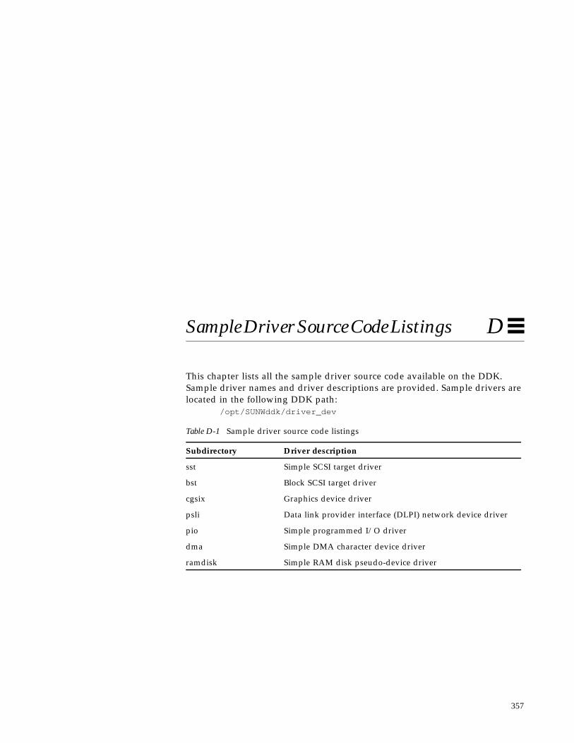
357
Sample Driver Source Code Listings D
This chapter lists all the sample driver source code available on the DDK.Sample driver names and driver descriptions are provided. Sample drivers arelocated in the following DDK path:
/opt/SUNWddk/driver_dev
Table D-1 Sample driver source code listings
Subdirectory Driver description
sst Simple SCSI target driver
bst Block SCSI target driver
cgsix Graphics device driver
psli Data link provider interface (DLPI) network device driver
pio Simple programmed I/O driver
dma Simple DMA character device driver
ramdisk Simple RAM disk pseudo-device driver

358 Writing Device Drivers—August, 1994
D

357
Index
Aadb(1) command, 246add_drv(1M) command, 227address spaces, 2, 18attach(9E) entry point, 95autoconfiguration
of block devices, 171of character devices, 148of SCSI drivers, 199routines, 49
autovectored interrupts, 107
Bbinary compatibility, 4block driver
autoconfiguration, 171entry points, 50slice number, 171
block interrupt cookie, 52burst sizes, 135bus
architectures, 14interrupt levels, 106SCSI, 189
bus nexus device drivers, 5bus-master DMA, 124
byte-stream I/O, 42
Ccache, 140callback functions, 51, 102, 134cb_ops(9S) structure, 88, 170character device drivers, 42, 147
entry points for, 50compiler modes, 65compiling/linking a driver, 226condition variables, 344
and interface functions, 344and mutex locks, 77, 277routines for, 78
configuration file, deviceattach(9E), 95detach(9E), 100getinfo(9E), 102identify(9E), 91probe(9E), 93
configuration file, hardware, 226context of device driver, 52control registers
device context management of, 213cookie
DMA, 120types of, 52
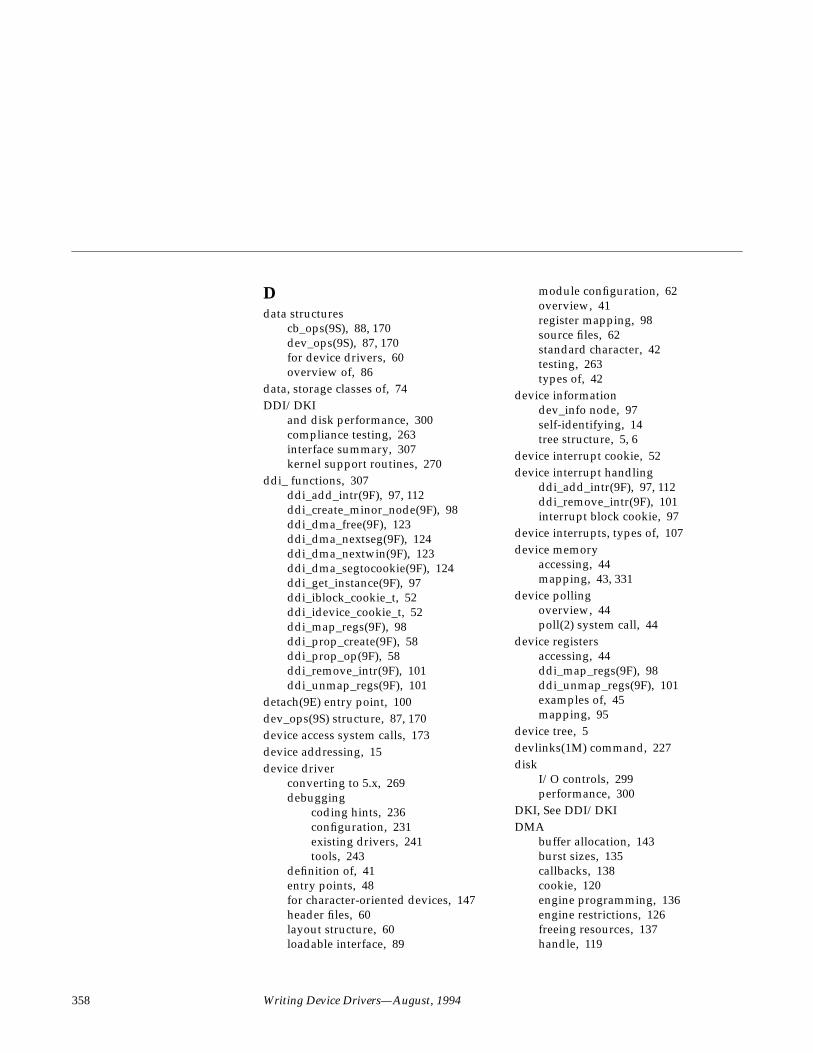
358 Writing Device Drivers—August, 1994
Ddata structures
cb_ops(9S), 88, 170dev_ops(9S), 87, 170for device drivers, 60overview of, 86
data, storage classes of, 74DDI/DKI
and disk performance, 300compliance testing, 263interface summary, 307kernel support routines, 270
ddi_ functions, 307ddi_add_intr(9F), 97, 112ddi_create_minor_node(9F), 98ddi_dma_free(9F), 123ddi_dma_nextseg(9F), 124ddi_dma_nextwin(9F), 123ddi_dma_segtocookie(9F), 124ddi_get_instance(9F), 97ddi_iblock_cookie_t, 52ddi_idevice_cookie_t, 52ddi_map_regs(9F), 98ddi_prop_create(9F), 58ddi_prop_op(9F), 58ddi_remove_intr(9F), 101ddi_unmap_regs(9F), 101
detach(9E) entry point, 100dev_ops(9S) structure, 87, 170device access system calls, 173device addressing, 15device driver
converting to 5.x, 269debugging
coding hints, 236configuration, 231existing drivers, 241tools, 243
definition of, 41entry points, 48for character-oriented devices, 147header files, 60layout structure, 60loadable interface, 89
module configuration, 62overview, 41register mapping, 98source files, 62standard character, 42testing, 263types of, 42
device informationdev_info node, 97self-identifying, 14tree structure, 5, 6
device interrupt cookie, 52device interrupt handling
ddi_add_intr(9F), 97, 112ddi_remove_intr(9F), 101interrupt block cookie, 97
device interrupts, types of, 107device memory
accessing, 44mapping, 43, 331
device pollingoverview, 44poll(2) system call, 44
device registersaccessing, 44ddi_map_regs(9F), 98ddi_unmap_regs(9F), 101examples of, 45mapping, 95
device tree, 5devlinks(1M) command, 227disk
I/O controls, 299performance, 300
DKI, See DDI/DKIDMA
buffer allocation, 143burst sizes, 135callbacks, 138cookie, 120engine programming, 136engine restrictions, 126freeing resources, 137handle, 119

359
limits, 127locking, 131object, 119operations, 124private buffer allocation, 143register structure, 134resource allocation, 131resource interfaces, 315segment, 120transfers, 156types of, 122window, 120
driver entry points, 313attach(9E), 95definition of, 48detach(9E), 100identify(9E), 91probe(9E), 93prop_op(9E), 58
DVMASBus slots that support, 17
dynamic loading, 3dynamic memory allocation, 54
Eentry points, See driver entry pointsexternal registers, 25
Ffilesystem I/O, 169fini(9E), 49, 91first-party DMA, 125
Ggeographical addressing, 15graphics devices
device context management of, 213
Hhardware configuration file, 226header files for device drivers, 60
II/O
control overview, 43disk controls, 299filesystem structure, 169miscellaneous control of, 165multiplexing, 162port access, 331programmed transfers, 154scatter/gather structures, 153
identify(9E) entry point, 91info(9E), 49init(9E), 49, 91instance numbers, 92internal mode registers, 25internal sequencing logic, 25interrupt cookie, See cookieinterrupt handling
block interrupt cookie, 52device interrupt cookie, 52interfaces for, 322overview, 52registering a handler, 95
interruptscommon problems with, 25registering, 97specification of, 106types of, 107
inumber, 97
Kkadb(1M) command, 246kernel modules
directory of, 227dynamic loading, 3
kernel threads, 72kernel, definition of, 1keywords, new, 66

360 Writing Device Drivers—August, 1994
Lleaf device drivers, 5lightweight process, 71linking a driver, 226loading drivers
add_drv(1M) command, 227compiling a driver, 226hardware configuration file, 226linking a driver, 226overview, 3
loading modules, 49, 227lock granularity, 295locking primitives, types of, 74LWP, 71
Mmemory mapping
device context management of, 43,213
memory modelSPARC, 13store buffers, 12
memory, allocation of, 54, 326minor device node, 98modldrv, 87modlinkage, 87module directory, 227module ID, getting, 228modunload(1M) command, 229mount(2) system call, 173multithreaded kernel, 73multithreading, 2
and condition variables, 78and lock granularity, 295and locking primitives, 74application threads, 71thread synchronization, 77
mutexfunctions, 76, 344locking order, 296locks, 75, 344related panics, 298
routines, 75
Nnode types, 99non-self-identifying devices, 15
Oobject locking, 131open(2) system call, 173
Ppadding structures, 47peripheral devices, 26physical DMA, 122physical SBus addresses
in SPARCstation 1, 17poll(2) system call, 44polled interrupts, 107polling, See device pollingprinting messages, 53probe(9E) entry point, 93programmed I/O, 154prop_op(9E) entry point, 58properties
ddi_prop_create(9F), 58ddi_prop_op(9F), 58overview of, 57prop_op(9E)entry point, 58types of, 57
PTE masks, 37
Qqueueing, 302
Rreaders/writer locks, 77registers, See control registers and device
registersrnumber, 98
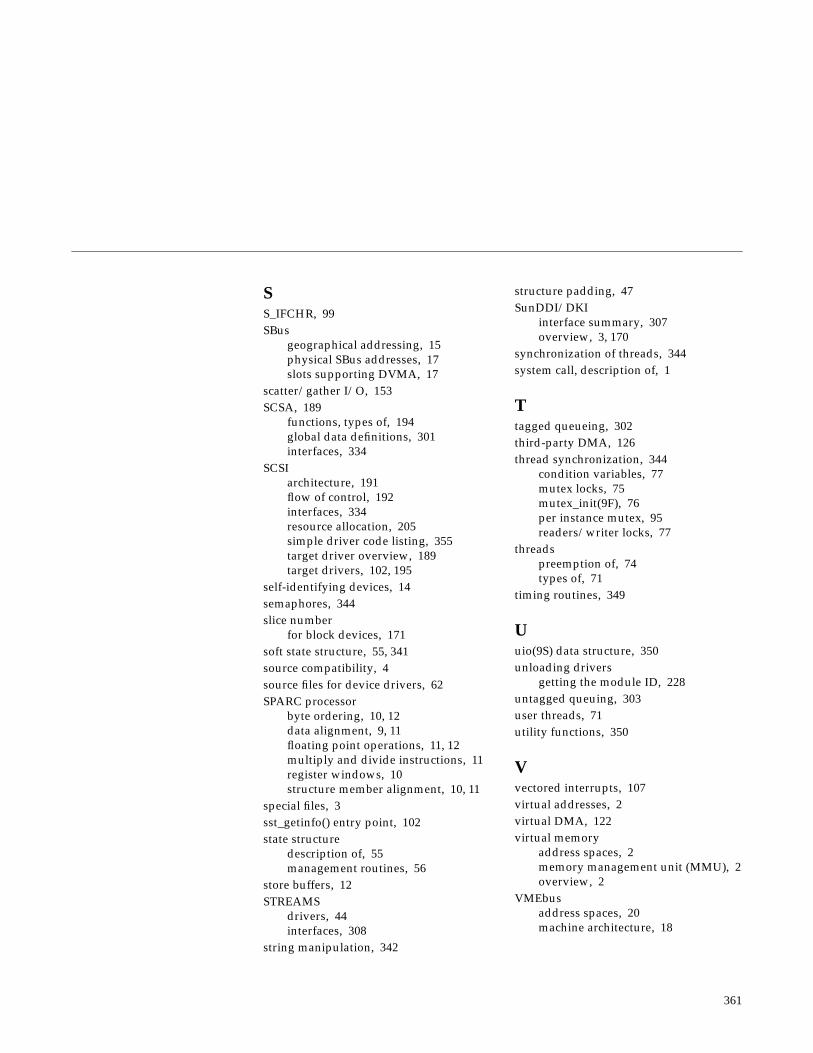
361
SS_IFCHR, 99SBus
geographical addressing, 15physical SBus addresses, 17slots supporting DVMA, 17
scatter/gather I/O, 153SCSA, 189
functions, types of, 194global data definitions, 301interfaces, 334
SCSIarchitecture, 191flow of control, 192interfaces, 334resource allocation, 205simple driver code listing, 355target driver overview, 189target drivers, 102, 195
self-identifying devices, 14semaphores, 344slice number
for block devices, 171soft state structure, 55, 341source compatibility, 4source files for device drivers, 62SPARC processor
byte ordering, 10, 12data alignment, 9, 11floating point operations, 11, 12multiply and divide instructions, 11register windows, 10structure member alignment, 10, 11
special files, 3sst_getinfo() entry point, 102state structure
description of, 55management routines, 56
store buffers, 12STREAMS
drivers, 44interfaces, 308
string manipulation, 342
structure padding, 47SunDDI/DKI
interface summary, 307overview, 3, 170
synchronization of threads, 344system call, description of, 1
Ttagged queueing, 302third-party DMA, 126thread synchronization, 344
condition variables, 77mutex locks, 75mutex_init(9F), 76per instance mutex, 95readers/writer locks, 77
threadspreemption of, 74types of, 71
timing routines, 349
Uuio(9S) data structure, 350unloading drivers
getting the module ID, 228untagged queuing, 303user threads, 71utility functions, 350
Vvectored interrupts, 107virtual addresses, 2virtual DMA, 122virtual memory
address spaces, 2memory management unit (MMU), 2overview, 2
VMEbusaddress spaces, 20machine architecture, 18

362 Writing Device Drivers—August, 1994


