WRS-SST Series Wireless Sensing System Tools Technical Bulletin2
WRS-SST Series Wireless Sensing System ToolsTechnical BulletinWRS-SST-100, WRS-SST-101
Document Introduction
This document describes the WRS-SST Series Wireless Sensing System Tools, their features and functions, how to set up and operate them, how to connect them to a laptop computer, and how to display and interpret data provided by them.
Note: The WRS-SST-101 Wireless Sensing System Tool (CE Mark compliant model) has a reduced transmission power (10 dBm) and transmission range to comply with the requirements of select countries.
This document does not describe how to install, commission, or operate One-to-One or Many-to-One wireless room temperature sensing systems. This document also does not describe how to determine the optimum locations for sensors and receivers in wireless room temperature sensing systems.
Related Documentation Table 1: One-to-One and Many-to-One System Related DocumentsFor Information On See Document LIT or Part Number
Locating and Installing WRS-TTx Series Sensors in One-to-One and Many-to-One Wireless Temperature Sensing Systems
WRS-TTx Series Wireless Room Temperature Sensors Installation Instructions
Part No. 24-10126-19
Locating, Mounting, and Wiring TE-7800 Series Receivers
TE-7800 Series Receivers for One-to-One Wireless Room Temperature Sensing Systems Installation Instructions
Part No. 24-10139-8
Commissioning, Configuring, Operating, and Troubleshooting TE-7800 Series Receivers, WRS-TTx Series Sensors, and the One-to-One Wireless Temperature Sensing System
TE-7800 Series One-to-One Wireless Room Temperature Sensing System Technical Bulletin
LIT-12011097
Locating, Mounting, and Wiring WRS-RTN Series Receivers
WRS-RTN Series Receivers for Many-to-One Wireless Room Temperature Sensing Systems Installation Instructions
Part No. 24-10126-0
Estimating the Required Number of WRS-RTN Series Receivers and Determining the Optimum Sensor and Receiver Locations in Many-to-One Applications; Commissioning, Configuring, Operating, and Troubleshooting WRS-RTN Series Receivers, WRS-TTx Series Sensors, and the Many-to-One Wireless Temperature Sensing System
WRS Series Many-to-One Wireless Room Temperature Sensing System Technical Bulletin
LIT-12011095
WRS-SST Series Wireless Sensing System Tools Technical Bulletin 3
WRS-SST Series Wireless Sensing System Tools Overview
The WRS-SST Series Wireless Sensing System Tools are optional, lightweight, portable, battery-powered, wireless receivers designed to receive wireless data transmissions from WRS-TTx Series Sensors, TE-7800 Series Receivers, and WRS-RTN Series Receivers in One-to-One and Many-to-One sensing system applications (Figure 1).
When connected to a properly configured laptop computer, the sensing system tool receives wireless data transmissions from specified sensors or receivers, and display Radio Frequency (RF) signal strength data, zone temperature and occupancy data, and wireless device information in the tool’s User Interface (UI) in a HyperTerminal window on the laptop screen.
The WRS-SST Series Sensing System Tool features multiple modes of operation to serve two primary purposes:
• testing the RF signal strength between sensing system device locations, which helps to determine the optimum locations for sensors and receivers in wireless room temperature sensing system applications prior to system installation
• providing information about operating sensing system applications, which helps to troubleshoot existing wireless room temperature sensing system applications after installation
Note: The WRS Series Many-to-One Wireless Room Temperature Sensing System supports two methods of Internet Protocol (IP) address assignments: static and Dynamic Host Configuration Protocol (DHCP). To use the WRS-SST Series Tool in the Many-to-One monitor mode (only) to monitor an existing WRS-RTN Series Receiver configured for dynamic IP addressing, the receiver must be date coded 0734 or later. All other WRS-SST Series Tool modes do not require a special date-coded WRS-RTN Series Receiver.
Figure 1: WRS-SST Series Wireless Sensing System Tool, Physical Features and Dimensions (in./mm)
WRS-SST-100R
F S
IGN
AL
RF ADDRESS
OFF
ON
256
128
64 32 16 8 4 2 1
OmnidirectionalIndoor Antenna
RF SignalLED
WIRELESSSENSING SYSTEM
TOOL
RF SIGNAL LED
Steady On
3 Blinks
2 Blinks
1 Blinks
Ready for Operation
Excellent Signal Strength
Good Signal Strength
Weak Signal Strength
ON OFF
RS-23219.2K
ON/OFFSwitch
SerialPort
RF AddressDIP Switch
Block
5-1/2140
5-3/4146
4-13/16122
2-1/1652
FIG
:dm
nsns
WRS-SST Series Wireless Sensing System Tools Technical Bulletin4
You can configure the tool and laptop computer to collect wireless sensing system information and save it to a text file on the laptop. The text files can be printed from the laptop. You can also use the tool to collect RF signal strength and temperature trend data from zones in your sensing system applications.
WRS-SST Series Tools Modes of Operation
The sensing system tool has five modes of operation: Stand-Alone mode, One-to-One receiver mode, Many-to-One receiver mode, One-to-One monitor mode, and Many-to-One monitor mode.
In Stand-Alone mode, the sensing system tool is not connected to a laptop computer. When the tool is connected to a laptop computer, you can select from the remaining four modes of operation that are enabled on the Main menu in the tool’s UI on the laptop screen. The mode selected determines the type of sensing system that the tool monitors and the information fields displayed on the laptop screen.
Stand-Alone Mode
In Stand-Alone mode, the sensing system tool is not connected to a laptop computer, and the tool operates like a portable, battery-powered receiver. The sensing system tool associates with and receives data transmissions from a single WRS-TTx Series Sensor that is configured as a test sensor. In Stand-Alone mode, the RF signal strength between the sensor and tool is indicated by a series of flashes or blinks on the sensor and tool Light-Emitting Diodes (LEDs). See Rapid Transmit Mode and RF Signal Strength LEDs on page 12 more information on LED RF signal strength indication.
Typically, you use the Stand-Alone mode to quickly test the RF signal strength between the intended receiver and sensor locations prior to installing a One-to-One or Many-to-One sensing system. See Using the WRS-SST Series Tool in Stand-Alone Mode on page 20 for detailed procedures.
Figure 2: WRS-SST Series Tool in Stand-Alone Mode
RF Signal Path
WRS-TTx Series SensorSet Up as a Test Sensorin Rapid Transmit Mode
The number of flashes (1, 2, or 3) of thetest sensor’s occupancy override LED
indicate the RF signal strength betweenthe sensor and the sensing system tool.
WRS-SST Series WirelessSensing System Tool in Stand-Alone
Mode and Positioned in aPotential Receiver Location
FIG
:wrs
_sst
_100
_stn
dln
Potential Location for aWRS-TTx Series Sensor
Move the test sensorto test other potential
sensor locations.
Potential Location for aWRS-TTx Series Sensor
WRS-SST Series Wireless Sensing System Tools Technical Bulletin 5
One-to-One Receiver Mode
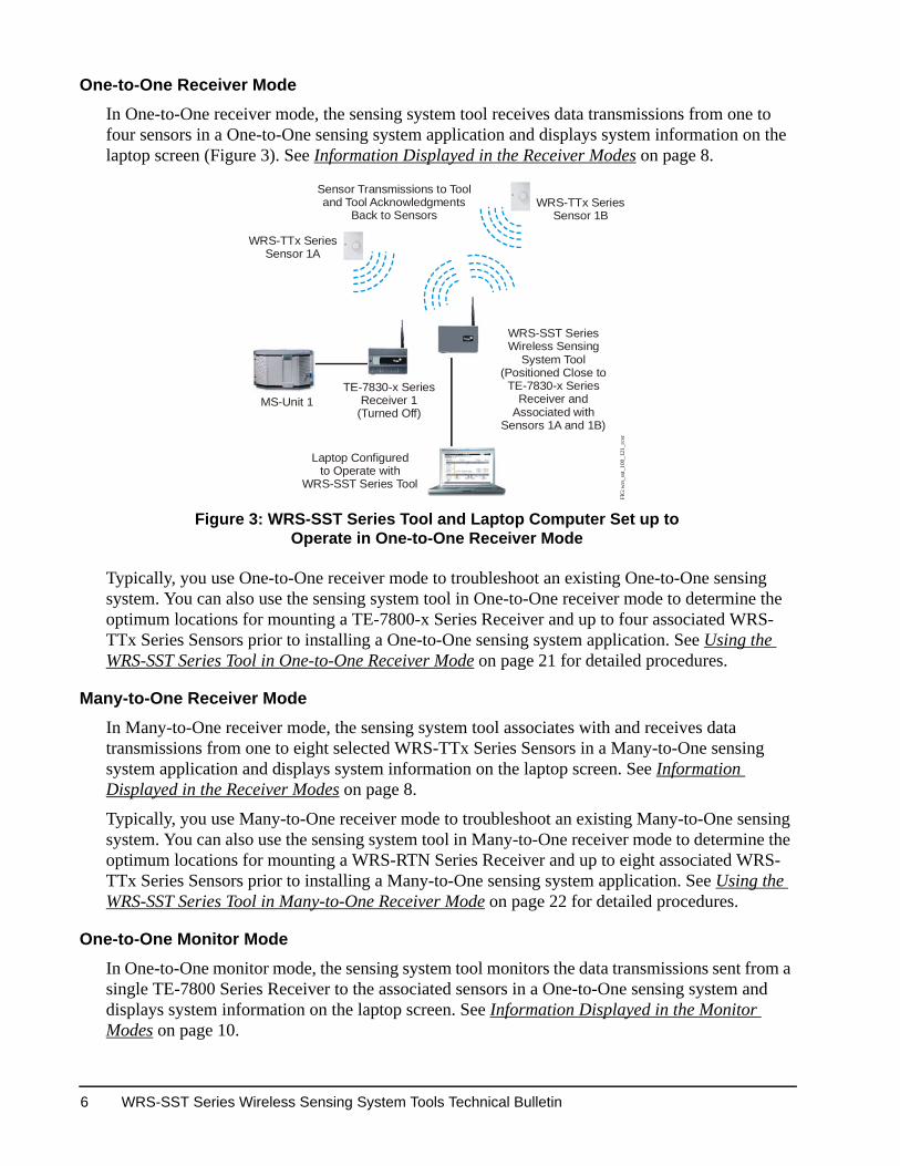
In One-to-One receiver mode, the sensing system tool receives data transmissions from one to four sensors in a One-to-One sensing system application and displays system information on the laptop screen (Figure 3). See Information Displayed in the Receiver Modes on page 8.
Typically, you use One-to-One receiver mode to troubleshoot an existing One-to-One sensing system. You can also use the sensing system tool in One-to-One receiver mode to determine the optimum locations for mounting a TE-7800-x Series Receiver and up to four associated WRS-TTx Series Sensors prior to installing a One-to-One sensing system application. See Using the WRS-SST Series Tool in One-to-One Receiver Mode on page 21 for detailed procedures.
Many-to-One Receiver Mode
In Many-to-One receiver mode, the sensing system tool associates with and receives data transmissions from one to eight selected WRS-TTx Series Sensors in a Many-to-One sensing system application and displays system information on the laptop screen. See Information Displayed in the Receiver Modes on page 8.
Typically, you use Many-to-One receiver mode to troubleshoot an existing Many-to-One sensing system. You can also use the sensing system tool in Many-to-One receiver mode to determine the optimum locations for mounting a WRS-RTN Series Receiver and up to eight associated WRS-TTx Series Sensors prior to installing a Many-to-One sensing system application. See Using the WRS-SST Series Tool in Many-to-One Receiver Mode on page 22 for detailed procedures.
One-to-One Monitor Mode
In One-to-One monitor mode, the sensing system tool monitors the data transmissions sent from a single TE-7800 Series Receiver to the associated sensors in a One-to-One sensing system and displays system information on the laptop screen. See Information Displayed in the Monitor Modes on page 10.
Figure 3: WRS-SST Series Tool and Laptop Computer Set up to Operate in One-to-One Receiver Mode
WRS-TTx SeriesSensor 1A
WRS-TTx SeriesSensor 1B
Sensor Transmissions to Tooland Tool Acknowledgments
Back to Sensors
MS-Unit 1TE-7830-x Series
Receiver 1(Turned Off)
Laptop Configuredto Operate with
WRS-SST Series Tool
WRS-SST SeriesWireless Sensing
System Tool (Positioned Close to
TE-7830-x SeriesReceiver and
Associated withSensors 1A and 1B)
FIG
:wrs
_sst
_100
_121
_rcv
r
WRS-SST Series Wireless Sensing System Tools Technical Bulletin6
Typically, you use One-to-One monitor mode to troubleshoot an existing One-to-One sensing system. One-to-One monitor mode is especially useful in troubleshooting One-to-One applications where the TE-7800 Series Receiver is not easily accessible. See Using the WRS-SST Series Tool in One-to-One Monitor Mode on page 24 for detailed procedures.
Many-to-One Monitor Mode
In Many-to-One monitor mode, the sensing system tool monitors the data transmissions from a WRS-RTN Series Receiver to the associated sensors in a Many-to-One sensing system and displays system information on the laptop screen (Figure 4). See Information Displayed in the Monitor Modes on page 10.
To enable the sensing system tool to monitor a WRS-RTN Series Receiver, you enter the receiver’s IP address in the tool UI. The sensing system tool monitors all data transmissions sent by the receiver and can provide information about each sensor associated with the monitored receiver. See Using the WRS-SST Series Tool in Many-to-One Monitor Mode on page 25 for detailed procedures.
Note: To use the WRS-SST Series Tool in the Many-to-One monitor mode (only) to monitor an existing WRS-RTN Series Receiver configured for dynamic IP addressing, the receiver must be date coded 0734 or later. All other WRS-SST Series Tool modes do not require a special date-coded WRS-RTN Series Receiver.
Note: Metasys® system Release 3.1 or later software is required to employ dynamic IP addressing on the WRS-RTN Series Receiver.
Figure 4: WRS-SST Series Tool and Laptop Set up to Operate in Many-to-One Monitor Mode
WRS-TTx Series Sensor 1
WRS-RTN SeriesReceiver
WRS-SST SeriesWireless Sensing
System Tool
WRS-TTx SeriesSensor 2
WRS-TTx Series Sensor 3
Sensor Transmissions to Receiverand Receiver Acknowledgments
Back to Sensors
Laptop Configuredto Operate with
WRS-SST Series Tool
The receiver acknowledgmentssent back to the sensors are alsoreceived by the WRS-SST Series
Tool in Monitor mode.IP Ethernet
FIG
:wrs
_sst
_100
_m21
_mnt
r
WRS-SST Series Wireless Sensing System Tools Technical Bulletin 7
Information Provided by the WRS-SST Series Tool
Data transmissions from sensors and receivers in One-to-One and Many-to-One sensing systems contain RF signal strength information, zone occupancy status, zone temperature and setpoint status, sensor identification information, sensing system device status, and sensor battery status. When a data transmission is received by the sensing system tool, some of this information is displayed in a line of text in a HyperTerminal window on the laptop screen. The information displayed on the laptop screen depends on the mode of operation that the sensing system tool is in.
Information Displayed in the Receiver Modes
In the receiver modes, the sensing system tool associates with and receives data transmissions from selected WRS-TTx Series Sensors. In a receiver mode, values for the following information fields are displayed, on a line of text in the tool’s UI, for each sensor transmission received by the tool (Figure 5).
Tool Clock Time
The displayed time is the time in hours, minutes, and seconds according to the sensing system tool’s 24-hour time clock (for example, 13:00:24). The sensing system tool’s clock is set in the tool UI on the laptop computer. The clock time is reset to 00:00:00 every time the sensing system tool is turned off (or loses battery power). See Setting the WRS-SST Series Tool Clock on page 20 for more information.
Property Code and Transmitter ID Values
The UI displays the WRS-TTx Series Sensor Property Code and Transmitter ID values (sensor address) for the WRS-TTx Series Sensor generating the line of information (for example, Prop00 ID 257). These values are set on the sensor DIP switch blocks. One-to-One sensors do not use a Property Code value, and in One-to-One applications, the sensor Property Code value is always 00.
Figure 5: Typical Information Displayed in HyperTerminal Window on Laptop Screen When the WRS-SST Series Tool Is in a Receiver Mode
WRS-SST Series Wireless Sensing System Tools Technical Bulletin8
Serial Number
The UI displays the sensor’s unique serial number in hexidecimal characters (for example, Sn00001A). No two sensors have the same serial number.
Temperature Setpoint Value
The temperature setpoint value is displayed in the UI as a percentage of the sensor’s total adjustment range (for example, SetPt 070%).
The WRS-TTP0000-x and WRS-TTS0000-x Series models have a setpoint adjustment dial, and the displayed setpoint value is a percentage (0 to 100%) of the total setpoint adjustment range (depending on the dial position). When a sensor’s setpoint dial is adjusted, the setpoint value (percentage) changes, and the new value is displayed in the next line of text generated by a sensor transmission.
The WRS-TTR000-x Series models do not have an adjustment dial, and SetPt 100% is always displayed in this field.
Note: Actual zone temperature setpoints are configured in the target field controller, the Network Automation Engine (NAE) UI, or the Network Control Engine (NCE) UI. Refer to the TE-7800 Series One-to-One Wireless Room Temperature Sensing System Technical Bulletin (LIT-12011097) or the WRS Series Many-to-One Wireless Room Temperature Sensing System Technical Bulletin (LIT-12011095) for information on sensor adjustments and setting zone temperature values.
Sensed Temperature Value
The UI displays the current temperature in °C and °F sensed at the sensor (for example, Tmp +24.17C +75.51F).
Battery Power Status
The UI displays the current status of the sensor’s battery power (for example, Bat OK or Bat Lo [low]).
Zone Occupancy Override
The UI displays whether or not the sensor transmission has initiated zone occupancy override (for example, Occ Y = data transmission has initiated a zone occupancy override or Occ N = data transmission has not initiated a zone occupancy override).
Note: Pressing the occupancy override button on a sensor generates a manual data transmission and initiates an occupancy override command. Manually generated transmissions always display OccY. The zone occupancy parameters are configured in a (compatible) target field controller, the NAE UI, or the NCE UI. Refer to the TE-7800 Series One-to-One Wireless Room Temperature Sensing System Technical Bulletin (LIT-12011097) or the WRS Series Many-to-One Wireless Room Temperature Sensing System Technical Bulletin (LIT-12011095) for information on setting zone occupancy values.
WRS-SST Series Wireless Sensing System Tools Technical Bulletin 9
Rapid Transmit Mode Status
The UI appears if the sensor is in Rapid Transmit Mode (RTM) or not (for example, RpXmt Y or RpXmt N). When a WRS-TTx Series Sensor is forced into RTM, it generates a data transmission every 10 seconds. Each sensor data transmission generated in RTM is displayed in the UI as long as the sensing system tool is associated with the sensor. See Rapid Transmit Mode and RF Signal Strength LEDs on page 12 for more information.
Transmission Count
The UI displays the number of the data transmissions generated by a sensor. For example, XCnt025 is the 25th transmission sent by the sensor. The sensor can count up to 255 transmission, then it rolls the counter over to XCnt001.
When powered on, a sensor automatically sends a transmission approximately every 60 seconds. The first transmission received by a receiver or sensing system tool establishes the sensor to receiver/tool association, and XCnt000 is displayed. After the association is established, the sensor counts each subsequent sensor transmission (even if the transmission is not received). A missing transmission count indicates that a sensor data transmission was not received by the associated tool (in the receiver modes) or the monitored receiver (in the monitor modes).
RF Signal Strength
RF signal strength indicates the strength of the RF signal between the sensor and the associated sensing system tool, expressed in dBm, followed by the RF signal strength expressed as Excellent, Good, or Weak, followed by the signal strength expressed as a percent of the typical signal strength range (where -90 to -65 dBm equals 0 to 100%). For example, SgStr -29dB,E,100% where -29dB = -29 dBm signal, E = Excellent, and 100% = 100 percent of the optimum signal strength.
RF Quality
The RF quality value range of 50 to 110 represents the RF signal strength relative to the ambient RF interference impact on the RF signal (for example, RFQual 107). Displayed RF quality values of 80 or greater are considered adequate or excellent. Lower values indicate ambient RF interference may be impacting the data transmissions between a sensor and the associated tool or receiver.
Note: On the Metasys UI, the RF quality value range is converted to 0 to 100, where values of 50 or greater are considered adequate or excellent.
Information Displayed in the Monitor Modes
In the monitor modes, the sensing system tool is configured to monitor and display data transmissions sent to WRS-TTx Series Sensors by either a TE-7800 Series Receiver in a One-to-One system or a WRS-RTN Series Receiver in a Many-to-One system.
The sensing system tool monitors two types of data transmissions in monitor mode: association grants and acknowledgements.
WRS-SST Series Wireless Sensing System Tools Technical Bulletin10
An association grant is the initial reply generated by a receiver and sent to an unassociated WRS-TTx Series Sensor in response to a data transmission from the sensor. An association grant enables the sensor to establish and maintain an association with the receiver. If the association is broken, another association grant must be generated to reestablish the association.
An acknowledgement is a routine reply generated by a receiver and sent to an associated WRS-TTx Series Sensor to confirm a sensor data transmission. After a receiver generates an association grant and establishes an association with the sensor, the receiver replies to all subsequent sensor transmissions with an acknowledgement (until the association is broken). The vast majority of the data transmissions sent by a receiver are acknowledgements.
In the monitor modes, the sensing system tool monitors all of the association grants and acknowledgements sent by a single sensing system receiver to all of the WRS-TTx Series Sensors associated with that receiver. System information from the monitored transmission is displayed in the tool UI (Figure 6).
In the monitor modes, the sensing system tool UI displays many of the same fields displayed in the receiver modes. See Tool Clock Time, Property Code and Transmitter ID Values, Serial Number, Transmission Count, RF Signal Strength, and RF Quality in the Information Displayed in the Receiver Modes section for information on fields that are also displayed in the receiver modes and monitor modes. In the monitor modes, the following fields are also displayed.
Data Transmission Type
The UI displays the type of data transmission generated by the receiver, either an association grant (AssocGrnt) or an acknowledgement (SenAcknwl).
Frequency
The UI displays the Zigbee™ channel (number) on which the sensor data transmission was sent (for example, Freq20).
Figure 6: Typical Information Displayed in HyperTerminal Window on Laptop Screen When the WRS-SST Series Tool Is in a Monitor Mode
WRS-SST Series Wireless Sensing System Tools Technical Bulletin 11
Sensor Transmission Power
Sensor transmission power is a fixed value (for example, Spwr32). On WRS-TTx0000-0 Series Sensor models for the North American market, the radio transmitters are configured to transmit at the maximum power (32) which corresponds to 15 dBm; therefore, in North American applications, the sensor transmission power value should always be Spwr32. WRS-TTx0000-1 Series reduced transmission power (10 dBm) CE Mark compliant models are configured to transmit at the maximum power (10).
Receiver Transmission Power
Receiver transmission power is a fixed value (for example, Rpwr32). On TE-78x0-0 Series Receivers and the WRS-RTN0000-0 Receiver for the North American market, the radio transmitters are configured to transmit at the maximum power (32) which corresponds to 15 dBm; therefore, in North American sensing system applications, the receiver transmission power value should always be Rpwr32. TE78x0-1 Series and the WRS-RTN0000-1 reduced transmission power (10 dBm) CE Mark compliant models are configured to transmit at the maximum power (10).
RF Signal Strength
In the monitor modes, RF signal strength indicates the signal strength between a WRS-TTx Series Sensor and the associated receiver. See RF Signal Strength in the Information Displayed in the Receiver Modes section for more information on the RF signal strength value.
WRS-SST Series Tool Help
The sensing system tool can display Help pages in the UI. The Help pages have abbreviated information on the fields and values displayed in the UI and on how to set up the tool in each of the four modes of operation available when the tool is connected to a laptop computer. Select 6 in the tool’s Main menu to go to the tool Help pages. See Connecting a Laptop Computer to the WRS-SST Series Tool and Accessing the Tool UI on page 18 for procedures on accessing the Help pages.
Rapid Transmit Mode and RF Signal Strength LEDs
Pressing and holding the manual occupancy override button on a WRS-TTx Series Sensor for 3 seconds or more forces the sensor into RTM. In RTM, a WRS-TTx Series Sensor sends a data transmission once every 10 seconds. Many-to-One sensors remain in RTM for up to 100 seconds. One-to-One sensors remain in RTM for up to 30 minutes. After each RTM transmission, the sensor occupancy LED flashes on one, two, or three times every 10 seconds to indicate the RF signal strength between the sensor and the receiver or sensing system tool.
In the receiver modes, the RF SIGNAL LED on the sensing system tool blinks off one, two, or three times every 10 seconds to indicate the signal strength between the sensor and tool. In the monitor modes, the RF SIGNAL LED on a TE-7800 Series Receiver or the WIRELESS LED on a WRS-RTN Series Receiver blinks off one, two, or three times every 10 seconds to indicate the signal strength between the sensor and associated receiver.
• No flashes/blinks indicate no RF signal.
• One flash/blink indicates a weak RF signal.
WRS-SST Series Wireless Sensing System Tools Technical Bulletin12
• Two flashes/blinks indicate a good RF signal.
• Three flashes/blinks indicate an excellent RF signal.
Press (and quickly release) the manual occupancy override button on a WRS-TTx Series Sensor to terminate RTM and reset the sensor to normal operation.
Detailed Procedures
Requirements
To perform the following procedures and troubleshoot a wireless sensing system, you need:
• a WRS-SST Series Wireless Sensing System Tool (with four 1.5 V, AA batteries)
• a WRS-TTx Series Sensor (for using the sensing system tool in Stand-Alone mode)
• a laptop computer with an available nine-pin serial Communication (COM) port or USB port (for using the sensing system tool in the receiver modes or monitor modes)
• a nine-pin, male-to-male, null modem serial cable for connecting the sensing system tool to the laptop COM port
Note: On laptop computers without a nine-pin serial port, use a USB to RS-232 adaptor for connecting the tool to a USB port. The Keyspan High Speed USB Serial Adaptor (Part No. USA-19HS) is compatible with the WRS-SST Series Tool. Other adaptors may also be compatible. Follow the manufacturer’s instructions for installing and operating the adaptor.
• the sensor address values/settings for the systems you are troubleshooting
• TE-7800 Series Receiver RF address values/settings for One-to-One systems
• WRS-RTN Series Receiver IP addresses for Many-to-One systems
Note: To use a WRS-RTN Series Receiver employing dynamic IP addressing in conjunction with a WRS-SST Series Tool in the Many-to-One monitor mode (only), the receiver must be date coded 0734 or later. All other WRS-SST Series Tool modes do not require a special date-coded WRS-RTN Series Receiver.
Note: A WRS-RTN Series Receiver that employs dynamic IP addressing requires Metasys system Release 3.1 or later software.
• a copy of the TE-7800 Series One-to-One Wireless Room Temperature Sensing System Technical Bulletin (LIT-12011097) for troubleshooting One-to-One systems or a copy of the WRS Series Many-to-One Wireless Room Temperature Sensing System Technical Bulletin (LIT-12011095) for troubleshooting Many-to-One systems
Setting Up Your Laptop Computer and HyperTerminal
The sensing system tool is designed to connect to a laptop COM port with a nine-pin null modem serial cable or to a USB port with a RS-232 serial to USB adaptor and a nine-pin null modem serial cable.
WRS-SST Series Wireless Sensing System Tools Technical Bulletin 13
After the sensing system tool is connected to a laptop computer configured with a custom HyperTerminal connection, you can display the tool UI, initiate tool commands in the UI, and display wireless sensing system data on the laptop. You can also set the sensing system tool and laptop computer to generate and save sensing system data in text files and then print the data text files.
To display the sensing system tool UI properly, you must create a custom connection file in the HyperTerminal application on your laptop computer. Creating a custom connection file enables you to quickly connect to the sensing system tool to your laptop computer and display sensing system information in a properly sized HyperTerminal window.
To configure a custom connection file in HyperTerminal for connecting your laptop computer to the sensing system tool:
1. Start your laptop.
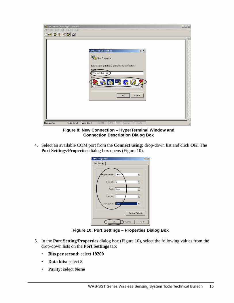
2. Open the HyperTerminal application. Click Start > Programs > Accessories > Communications > HyperTerminal (Figure 7). A New Connection - HyperTerminal window and the Connection Description dialog box opens (Figure 8).
3. Enter a descriptive name (for example, WRS-SST-100 Tool) and select an icon for the new connection file. Click OK. The Connect To dialog box opens (Figure 9).
Figure 7: Opening the HyperTerminal Application
Figure 9: Connect To Dialog Box
WRS-SST Series Wireless Sensing System Tools Technical Bulletin14
4. Select an available COM port from the Connect using: drop-down list and click OK. The Port Settings/Properties dialog box opens (Figure 10).
5. In the Port Setting/Properties dialog box (Figure 10), select the following values from the drop-down lists on the Port Settings tab:
WRS-SST Series Wireless Sensing System Tools Technical Bulletin 15
• Stop bits: select 1
• Flow control: select None
6. Click OK (Figure 10). The Properties dialog box (for your custom connection) opens (Figure 11).
7. In the Properties dialog box, click the Settings tab. Select VT100 from the drop-down list in the Emulation: section (Figure 11). After you select VT100, the Terminal Setup... button is active.
8. Click the active Terminal Setup... button to open the Terminal Settings dialog box (Figure 12).
9. In the Terminal Settings dialog box, select 132 column mode in the Terminal Modes section (to change the HyperTerminal character column width from 80 characters to 132). Click OK to save the setting and close the Terminal Settings dialog box.
10. Click OK in the Properties dialog box to close the Properties dialog box.
Figure 11: Properties Dialog Box
Figure 12: Terminal Settings Dialog Box
WRS-SST Series Wireless Sensing System Tools Technical Bulletin16
11. Click File on the HyperTerminal window menu bar and select Properties from the drop-down menu to reopen the Properties dialog box.
12. Select the Settings tab and click OK in the Properties dialog box to save the Properties settings and close the Properties dialog box.
13. Click View again on the HyperTerminal window menu bar and select Font from the drop-down menu to open the Font dialog box (Figure 13).
14. In the Font dialog box, select Courier New in the Font: drop-down list, select Regular in the Font style: drop-down list, and select 9 in the Size: drop-down list (Figure 13). Click OK to save the settings.
15. Click View on the HyperTerminal window menu bar and select Snap from the drop-down menu (to automatically expand the HyperTerminal window width to the match the 132 character column width).
16. Select File in the HyperTerminal menu bar and click Save on the drop-down menu to save the custom HyperTerminal connection for use with the tool.
The laptop computer is now set up with a custom HyperTerminal and ready to connect to an operational sensing system tool.
Installing or Replacing the WRS-SST Series Tool Batteries
The sensing system tool is powered by four AA alkaline batteries. The four AA alkaline batteries are included in the box with a new sensing system tool.
To install the sensing system tool batteries:
1. Ensure that the sensing system tool’s ON/OFF switch is in the OFF position.
2. Unscrew (remove and save) the omnidirectional antenna from the coaxial antenna connector on the sensing system tool.
3. Remove the sensing system tool housing from the tool base by depressing the base locking tabs on the side of the tool housing and pulling the housing away from the tool base (Figure 14).
Figure 13: Font Dialog Box
WRS-SST Series Wireless Sensing System Tools Technical Bulletin 17
4. Remove the printed circuit board from the back of the tool housing by gently pulling the tabs (on the inside edges of the tool housing) outward to release the PC board. Lift the bottom of the PC board away from the housing and slide the PC board out.
5. Install (or replace) the four AA alkaline batteries. Ensure that the new batteries are installed in the correct position to maintain proper polarity. (Correct position and polarity is illustrated on the base of the battery holders under the batteries.)
Note: When replacing batteries, all four batteries should be replaced at the same time. Batteries removed from this device must be recycled or disposed of in accordance with local, national, and regional regulations. Only certified technicians or qualified building maintenance personnel should service Johnson Controls® products. Lithium batteries with a maximum cell voltage of 1.5 Volts can be substituted to extend the period between battery replacement. Do not mix lithium and alkaline batteries in this device.
6. Turn the tool on to ensure the tool batteries have a charge and are properly installed (the RF SIGNAL LED lights). Turn the tool off.
7. Carefully place the PC board back into the tool housing, reattach the housing to the tool base, and reinstall the omnidirectional antenna on the coaxial connector.
The sensing system tool is ready to connect to a laptop computer.
Connecting a Laptop Computer to the WRS-SST Series Tool and Accessing the Tool UI
The laptop computer must be configured with a custom HyperTerminal window before connecting to the sensing system tool and accessing the tool UI.
1. Ensure that the tool and the laptop are powered off.
2. Connect the null modem cable to the tool serial port and the laptop. (Or connect the RS-232 serial to USB adaptor and cables to the tool and laptop.)
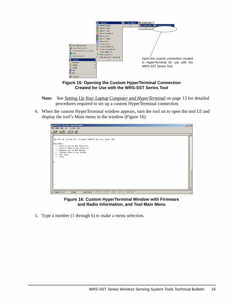
3. Power the laptop on and go to Start > Programs > Accessories > HyperTerminal to open the custom HyperTerminal connection (Figure 15).
Figure 14: Removing the WRS-SST Series Tool Housing from the Tool Base to Access the Printed Circuit Board and Batteries
Tool Base
Slots in Base(4 Total)
Base Locking Tabs(4 Tabs Total)
ToolHousing
FIG
:btt
ry_a
ccss
Two tabs, one on each inside edge of the sides of the housing, hold thePC board in the housing.
Coaxial AntennaConnector
WRS-SST Series Wireless Sensing System Tools Technical Bulletin18
Note: See Setting Up Your Laptop Computer and HyperTerminal on page 13 for detailed procedures required to set up a custom HyperTerminal connection.
4. When the custom HyperTerminal window appears, turn the tool on to open the tool UI and display the tool’s Main menu in the window (Figure 16).
5. Type a number (1 through 6) to make a menu selection.
Figure 15: Opening the Custom HyperTerminal ConnectionCreated for Use with the WRS-SST Series Tool
Open the custom connection createdin HyperTerminal for use with theWRS-SST Series Tool.
Figure 16: Custom HyperTerminal Window with Firmware and Radio Information, and Tool Main Menu
WRS-SST Series Wireless Sensing System Tools Technical Bulletin 19
Setting the WRS-SST Series Tool Clock
To set the clock on the sensing system tool:
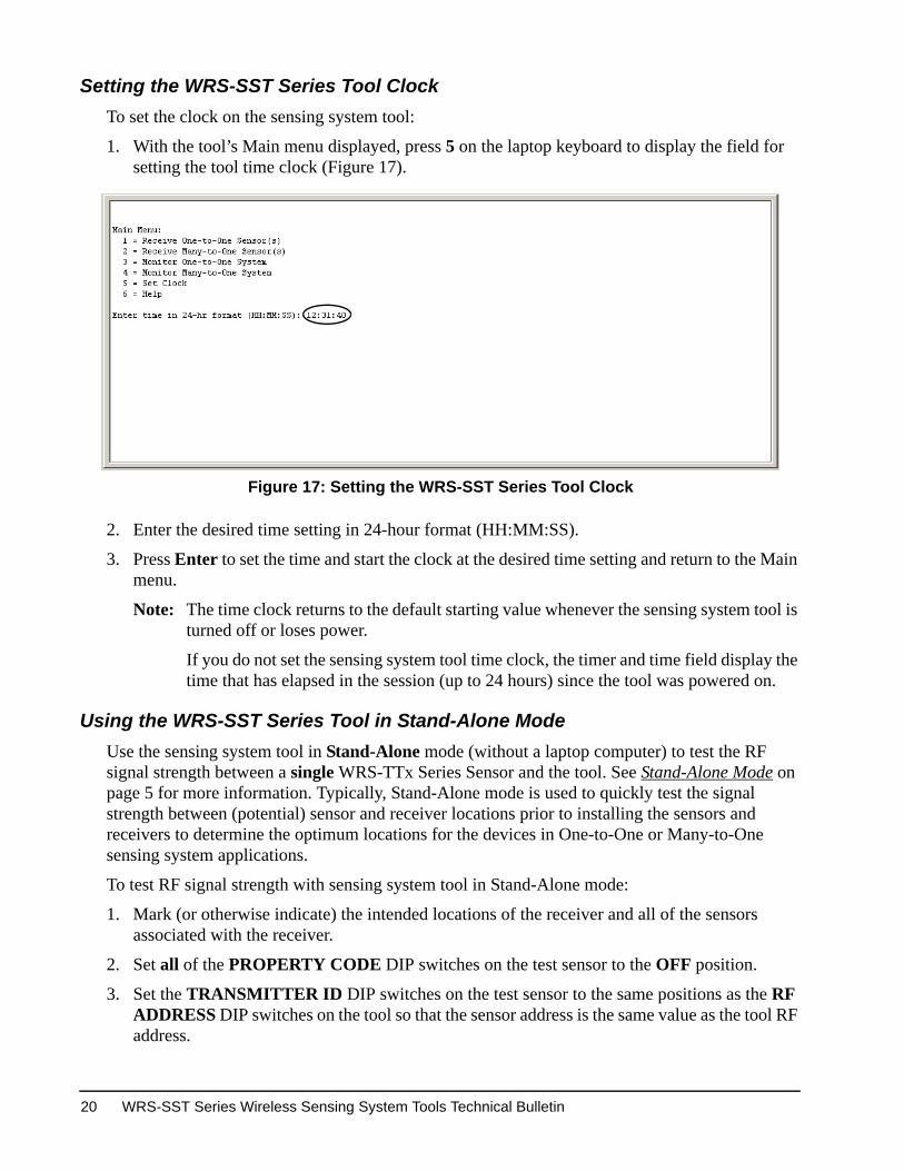
1. With the tool’s Main menu displayed, press 5 on the laptop keyboard to display the field for setting the tool time clock (Figure 17).
2. Enter the desired time setting in 24-hour format (HH:MM:SS).
3. Press Enter to set the time and start the clock at the desired time setting and return to the Main menu.
Note: The time clock returns to the default starting value whenever the sensing system tool is turned off or loses power.
If you do not set the sensing system tool time clock, the timer and time field display the time that has elapsed in the session (up to 24 hours) since the tool was powered on.
Using the WRS-SST Series Tool in Stand-Alone Mode
Use the sensing system tool in Stand-Alone mode (without a laptop computer) to test the RF signal strength between a single WRS-TTx Series Sensor and the tool. See Stand-Alone Mode on page 5 for more information. Typically, Stand-Alone mode is used to quickly test the signal strength between (potential) sensor and receiver locations prior to installing the sensors and receivers to determine the optimum locations for the devices in One-to-One or Many-to-One sensing system applications.
To test RF signal strength with sensing system tool in Stand-Alone mode:
1. Mark (or otherwise indicate) the intended locations of the receiver and all of the sensors associated with the receiver.
2. Set all of the PROPERTY CODE DIP switches on the test sensor to the OFF position.
3. Set the TRANSMITTER ID DIP switches on the test sensor to the same positions as the RF ADDRESS DIP switches on the tool so that the sensor address is the same value as the tool RF address.
Figure 17: Setting the WRS-SST Series Tool Clock
WRS-SST Series Wireless Sensing System Tools Technical Bulletin20
Note: Ensure that no other sensing system receivers or sensors with the same address are powered and nearby. Active sensing system devices with the same address as the sensing system tool and test sensor can interfere with RF signal strength testing.
The RF address value of 510 should be reserved for testing One-to-One sensing system applications. You can use an address value of 510 for the test sensor and sensing system tool to avoid interference from other One-to-One devices.
4. Position the tool at a location where you intend to mount the sensing system receiver, position the tool’s antenna in a vertical position (pointing up or down), and power the tool on.
Note: For the most accurate test results, locate the tool and position the tool antenna exactly as the receiver and receiver antenna would be located and positioned.
5. Power on the test sensor and press the occupancy override button for 3 seconds to force the test sensor into RTM.
6. Hold the test sensor upright and as close as possible to an intended sensor location for at least 10 seconds. The occupancy override LED should emit one to three rapid flashes, which indicates the RF signal strength between the test sensor and the tool. (See Rapid Transmit Mode and RF Signal Strength LEDs on page 12 for more information on RTM and RF signal strength indication.)
7. Hold the sensor in place for another 10 seconds to verify the test and record the results for the sensor location.
8. Move the test sensor to the next intended sensor location and repeat Steps 6 and 7.
9. Repeat Step 8 for each of the associated sensor locations.
10. If you have more receiver locations to test, move the sensing system tool and repeat Step 1 and Steps 4 through 9 for each receiver location.
Using the WRS-SST Series Tool in One-to-One Receiver Mode
In One-to-One receiver mode, the sensing system tool receives data transmissions from up to four WRS-TTx Series Sensors in a One-to-One application. Typically, you use the sensing system tool in One-to-One receiver mode to troubleshoot an existing One-to-One sensing system application. You can also use the sensing system tool in One-to-One receiver mode to determine the optimum locations for mounting a TE-7800 Series Receiver and up to four associated WRS-TTx Series Sensors prior to installing a One-to-One sensing system application. See One-to-One Receiver Mode on page 6 for more information.
WRS-SST Series Wireless Sensing System Tools Technical Bulletin 21
Before you use the tool in One-to-One receiver mode, you should:
• ensure that the sensor or sensors you are testing are turned on, and that they all have the same sensor address and that the address is a valid One-to-One sensor address (no Property Code value)
• ensure that the sensing system tool RF address is the same value as the sensor or sensors you are testing
• ensure that the TE-7800 Series Receiver (associated to the sensor or sensors you are testing) is turned off
• ensure that there are no other active receivers or sensors (near your test site) with the same address as the sensing system tool and sensors you are testing
• connect the laptop computer to the sensing system tool, open the custom HyperTerminal connection on the laptop, power the tool on, and set the tool clock to the desired time. See Connecting a Laptop Computer to the WRS-SST Series Tool and Accessing the Tool UI on page 18 and Setting the WRS-SST Series Tool Clock on page 20 for more information.
To use the sensing system tool in One-to-One receiver mode:
1. Position the sensing system tool next to (or in place of) the TE-7800 Series Receiver that is associated to the sensor or sensors you are testing.
2. Ensure the Main Menu is the active menu in the tool UI and then press 1 to place the tool in One-to-One receiver mode.
3. Wait for at least 1 minute. Each target sensor should associate with the tool and begin sending data transmissions to the tool approximately once every minute.
You can force any or all of the sensors you are testing into RTM to generate sensor transmission every 10 seconds. See Rapid Transmit Mode and RF Signal Strength LEDs on page 12 for more information.
You can collect information for as long as the sensing system tool batteries last, but the HyperTerminal window displays only the 24 most recent lines of text generated by the tool.
You can save the collected information to a file on the laptop computer and display the data in a text editor (such as Notepad) or word processing application or print the collected information to a printer connected to the laptop.
Use the information to troubleshoot your One-to-One application. See Information Displayed in the Receiver Modes on page 8 for more information.
Using the WRS-SST Series Tool in Many-to-One Receiver Mode
In Many-to-One receiver mode, the sensing system tool receives data transmissions from up to eight WRS-TTx Series Sensors in a Many-to-One application. Typically, you use the sensing system tool in Many-to-One receiver mode to troubleshoot an existing Many-to-One sensing system application. You can also use the sensing system tool in Many-to-One receiver mode to determine the optimum locations for mounting a WRS-RTN Series Receiver and up to eight associated WRS-TTx Series Sensors prior to installing a Many-to-One sensing system application. See Many-to-One Receiver Mode on page 6 for more information.
WRS-SST Series Wireless Sensing System Tools Technical Bulletin22
Before using the sensing system tool in Many-to-One receiver mode, you should:
• ensure that the (up to eight) sensors you are testing are turned on, and that they have a valid Many-to-One sensor address. Record the sensor addresses.
• ensure that the WRS-RTN Series Receiver (associated to the sensors you are testing) is turned off
• ensure that there are no other active sensors (near your test site) with any of the same sensor addresses as the sensors you are testing
• connect the laptop computer to the sensing system tool, open the custom HyperTerminal connection on the laptop, power the tool on, and set the tool clock to the desired time. See Connecting a Laptop Computer to the WRS-SST Series Tool and Accessing the Tool UI on page 18 and Setting the WRS-SST Series Tool Clock on page 20 for more information.
To use the sensing system tool in Many-to-One receiver mode:
1. Position the sensing system tool next to (or in place of) the WRS-RTN Series Receiver that is associated to the sensors you are testing.
2. Ensure the Main Menu is the active menu in the tool UI and then press 2 to place the tool in Many-to-One receiver mode and go to the Many-to-One receiver mode submenu.
3. Create a list of (up to eight) sensors that you want to associate with the tool. To create a list of sensors:
a. In the active submenu press 1 to display the Add Sensor to List fields.
b. Enter a target sensor’s Property Code value and Transmitter ID value in the property code field and Sensor ID field in the tool UI and press Enter to display the active submenu again.
c. In the active submenu press a number, 1 through 6, to perform the following options:
- 1 = Add Sensor to List
- 2 = Delete Sensor from List
- 3 = Delete All Sensors from List
- 4 = Display Sensor List
- 5 = List Complete, Display Sensor Messages
- 6 = Return to Main Menu
d. After you have added all of the target sensors to the list of sensors, press 5 to complete the list and begin displaying sensor message in the tool UI.
4. Wait for at least 1 minute. The sensors you are testing should associate with the tool and the tool should begin displaying sensor messages.
You can force any or all of the sensors you are testing into RTM to generate sensor transmission every 10 seconds. See Rapid Transmit Mode and RF Signal Strength LEDs on page 12 for more information.
You can collect information for as long as the sensing system tool batteries last, but the HyperTerminal window displays only the 24 most recent lines of text generated by the tool.
WRS-SST Series Wireless Sensing System Tools Technical Bulletin 23
You can save the collected information to a file on the laptop computer and display the data in a text editor (such as Notepad) or word processing application or print the collected information to a printer connected to the laptop.
Use the information to troubleshoot your Many-to-One application. See Information Displayed in the Receiver Modes on page 8 for more information.
Using the WRS-SST Series Tool in One-to-One Monitor Mode
In One-to-One monitor mode, the sensing system tool monitors the data transmissions from a TE-7800 Series Receiver that are sent to (up to four) associated WRS-TTx Series Sensors. Typically, you use the tool in One-to-One monitor mode to troubleshoot existing One-to-One sensing system applications. The One-to-One monitor mode is especially useful in troubleshooting One-to-One applications where the receiver is not easily accessible. See One-to-One Monitor Mode on page 6 for more information.
Before you use the tool in One-to-One monitor mode, you should:
• ensure that the sensor or sensors you are testing are turned on, and that they all have the same sensor address and that the address is a valid One-to-One sensor address (no Property Code value)
• ensure that the RF address value (RF ADDRESS DIP switch positions) on the TE-7800 Series Receiver match the sensor address value (TRANSMTTER ID DIP switch positions) of the sensor or sensors you are testing
• ensure that the TE-7800 Series Receiver is turned on
• ensure that the sensing system tool RF address value (RF ADDRESS DIP switch positions) matches the receiver you are monitoring
• ensure that no other active receivers or sensors with the same RF address value as the sensing system tool and receiver you are monitoring are near your test site
• connect the laptop computer to the sensing system tool, open the custom HyperTerminal connection on the laptop, power the tool on, and set the tool clock to the desired time. See Connecting a Laptop Computer to the WRS-SST Series Tool and Accessing the Tool UI on page 18 and Setting the WRS-SST Series Tool Clock on page 20 for more information.
To use the sensing system tool in One-to-One monitor mode:
1. Position the tool in a direct line-of-sight path with the target TE-7800 Series Receiver.
Note: For the WRS-SST-100 model, do not exceed the practical indoor limit of 200 ft (61 m). For the WRS-SST-101 model, do not exceed the practical indoor limit of 165 ft (50 m). For either model, do not place the tool less than 3 ft (1 m) from the target receiver.
2. Ensure the Main Menu is the active menu in the tool UI and then press 3 to place the tool in One-to-One monitor mode. The tool attempts to sync up with the receiver. (This may take up to 30 seconds.) Then Synchronization achieved is displayed in the tool UI and the receiver messages are displayed in the UI as they are sent by the receiver.
You can force any or all of the sensors you are testing into RTM to generate sensor transmission every 10 seconds. See Rapid Transmit Mode and RF Signal Strength LEDs on page 12 for more information.
WRS-SST Series Wireless Sensing System Tools Technical Bulletin24
You can collect information for as long as the sensing system tool batteries last, but the HyperTerminal window displays only the 24 most recent lines of text generated by the tool.
You can save the collected information to a file on the laptop computer and display the data in a text editor (such as Notepad) or word processing application or print the collected information to a printer connected to the laptop.
Use the information to troubleshoot your One-to-One application. See Information Displayed in the Monitor Modes on page 10 for more information.
Using the WRS-SST Series Tool in Many-to-One Monitor Mode
In Many-to-One monitor mode, the sensing system tool monitors all of the data transmissions from a WRS-RTN Series Receiver that are sent to the associated WRS-TTx Series Sensors in a Many-to-One application. Typically, you use the tool in Many-to-One monitor mode to troubleshoot existing Many-to-One sensing system applications. The Many-to-One monitor mode is especially useful in troubleshooting Many-to-One applications where the receiver is not easily accessible. See Many-to-One Monitor Mode on page 7 for more information.
Note: Up to 60 WRS-TTx Series Sensors can be associated to an WRS-RTN Series Receiver, but the practical average is 10 to 20 sensors per receiver.
WRS-SST Series Wireless Sensing System Tools Technical Bulletin 25
Before you use the tool in Many-to-One monitor mode:
• ensure that the sensors in the Many-to-One application (you are testing) are turned on, and that they have a valid Many-to-One sensor address
• ensure that there are no other active Many-to-One sensors (near your test site) with any of the same sensor addresses as the sensors you are monitoring
• ensure that the WRS-RTN Series Receiver you are monitoring is configured with a valid static or dynamic IP address, and is turned on
• ensure that the sensors in the Many-to-One application are mapped to the WRS-RTN Series Receiver of the Wireless Supervisor on the NAE UI or NCE UI. Refer to the WRS Series Many-to-One Wireless Room Temperature Sensing System Technical Bulletin (LIT-12011095) for information on mapping sensors to WRS-RTN Series Receivers.
• ensure that there are no other active WRS-RTN Series Receivers (near your test site) with the same IP address as the receiver you are monitoring
• connect the laptop computer to the sensing system tool, open the custom HyperTerminal connection on the laptop, power the tool on, and set the tool clock to the desired time. See Connecting a Laptop Computer to the WRS-SST Series Tool and Accessing the Tool UI on page 18 and Setting the WRS-SST Series Tool Clock on page 20 for more information.
To use the sensing system tool in Many-to-One monitor mode:
1. Position the tool in a direct line-of-sight path with the target WRS-RTN Series Receiver.
Note: For the WRS-SST-100 model, do not exceed the practical indoor limit of 200 ft (61 m). For the WRS-SST-101 model, do not exceed the practical indoor limit of 165 ft (50 m). For either model, do not place the tool less than 3 ft (1 m) from the target receiver.
2. Ensure the Main Menu is the active menu in the tool UI and then press 4 to place the tool in Many-to-One monitor mode
3. Type the target WRS-RTN Series Receiver’s IP address and press Enter. If the receiver is configured with a static IP address, obtain the address from the IP address sticker on the front of the receiver. If the receiver is configured for dynamic IP addressing, obtain the address from the Advanced focus view of the Wireless Receiver object on the NAE or NCE. The tool attempts to sync up with the receiver. (This may take up to 30 seconds.) Then Synchronization achieved is displayed in the tool UI, and the receiver messages are displayed in the UI as they are sent by the receiver.
Note: To use the WRS-SST Series Tool in the Many-to-One monitor mode (only) to monitor an existing WRS-RTN Series Receiver configured for dynamic IP addressing, the receiver must be date coded 0734 or later. All other WRS-SST Series Tool modes do not require a special date-coded WRS-RTN Series Receiver.
Note: Metasys system Release 3.1 or later software is required to employ dynamic IP addressing on the WRS-RTN Series Receiver.
WRS-SST Series Wireless Sensing System Tools Technical Bulletin26
If the Many-to-One monitor mode of the WRS-SST Series Wireless Sensing System Tool does not function for a temperature sensing system configured for dynamic IP addressing, cycle the power on the receiver. Next, go to the Advanced focus view of the Wireless Receiver object on the NAE or NCE to obtain the IP address of the receiver, since it may have changed when the power was cycled on. Enter this receiver IP address into the WRS-SST Series Wireless Sensing System Tool.
You can force any or all of the sensors you are testing into RTM to generate sensor transmission every 10 seconds. See Rapid Transmit Mode and RF Signal Strength LEDs on page 12 for more information.
You can collect information for as long as the sensing system tool batteries last, but the HyperTerminal window displays only the 24 most recent lines of text generated by the tool.
You can save the collected information to a file on the laptop computer and display the data in a text editor (such as Notepad) or word processing application or print the collected information to a printer connected to the laptop.
Use the information to troubleshoot your Many-to-One application. See Information Displayed in the Monitor Modes on page 10 for more information.
Technical Specifications WRS-SST Series Wireless Sensing System Tools (Part 1 of 2)Power Requirements 6 VDC, Four AA Alkaline Batteries Included with Tool;
Approximate Battery Life: 72 Hours
Ambient Operating Temperature Limits
32 to 122°F (0 to 50°C)
Ambient Operating Humidity Limits
Less than 95% RH, Noncondensing
Ambient Storage Temperature Limits
-40 to 160°F (-40 to 71°C)
Ambient Storage Humidity Limits
Less than 90% RH, Noncondensing
RF Band Direct-Sequence, Spread-Spectrum, 2.4 GHz ISM Bands
Transmission Power WRS-SST-100 Tool: 15 dBm MaximumWRS-SST-101 Tool: 10 dBm Maximum
Transmission Range WRS-SST-100 Tool: 500 ft (152 m) Maximum Indoor Line-of-Sight: 200 ft (61 m) Practical Average IndoorWRS-SST-101 Tool: 375 ft (114 m) Maximum Indoor Line-of-Sight: 165 ft (50 m) Practical Average Indoor
Temperature System Accuracy 1F° (0.6C°) Over the Range of 55 to 85°F (13 to 29°C); 1.5F° (0.9C°) Over a Range of 32 to 55°F (0 to 13°C) and 85 to 110°F (29 to 43°C)
Terminations and Interfaces Nine-Pin, RS-232 Serial Port for Null Modem Serial Cable Connection to Laptop Computer
Materials Gray Plastic Housing with UL94-5VB Flammability Rating
WRS-SST Series Wireless Sensing System Tools Technical Bulletin 27
wer
mpliant
t is in ons of the
t conditions iable for
ontact:
UCT
ISTRICTCE 214142
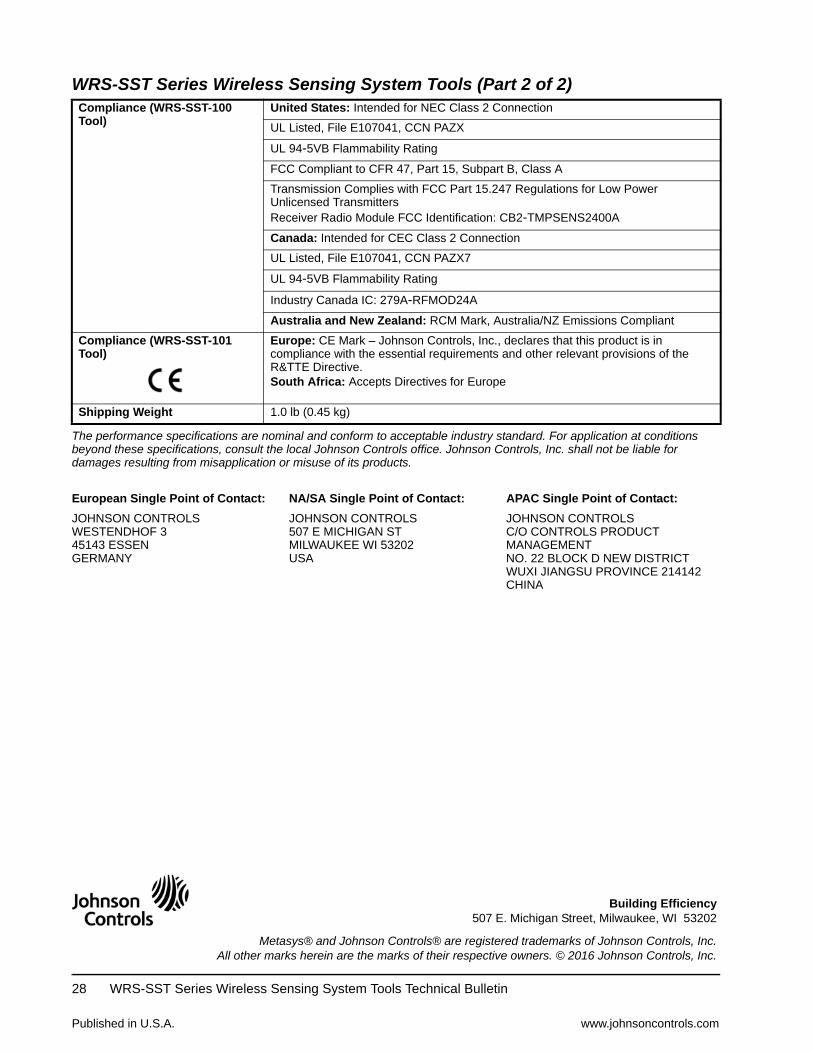
Compliance (WRS-SST-100 Tool)
United States: Intended for NEC Class 2 Connection
UL Listed, File E107041, CCN PAZX
UL 94-5VB Flammability Rating
FCC Compliant to CFR 47, Part 15, Subpart B, Class A
Transmission Complies with FCC Part 15.247 Regulations for Low PoUnlicensed TransmittersReceiver Radio Module FCC Identification: CB2-TMPSENS2400A
Canada: Intended for CEC Class 2 Connection
UL Listed, File E107041, CCN PAZX7
UL 94-5VB Flammability Rating
Industry Canada IC: 279A-RFMOD24A
Australia and New Zealand: RCM Mark, Australia/NZ Emissions Co
Compliance (WRS-SST-101 Tool)
Europe: CE Mark – Johnson Controls, Inc., declares that this produccompliance with the essential requirements and other relevant provisiR&TTE Directive.South Africa: Accepts Directives for Europe
Shipping Weight 1.0 lb (0.45 kg)
The performance specifications are nominal and conform to acceptable industry standard. For application abeyond these specifications, consult the local Johnson Controls office. Johnson Controls, Inc. shall not be ldamages resulting from misapplication or misuse of its products.
European Single Point of Contact: NA/SA Single Point of Contact: APAC Single Point of C
JOHNSON CONTROLSWESTENDHOF 345143 ESSENGERMANY
JOHNSON CONTROLS507 E MICHIGAN STMILWAUKEE WI 53202USA
JOHNSON CONTROLSC/O CONTROLS PRODMANAGEMENTNO. 22 BLOCK D NEW DWUXI JIANGSU PROVINCHINA
WRS-SST Series Wireless Sensing System Tools (Part 2 of 2)
Published in U.S.A. www.johnsoncontrols.com
WRS-SST Series Wireless Sensing System Tools Technical Bulletin28


![A Dimensions: [mm] B Recommended land pattern: [mm] D ... · 2013-03-12 2013-01-13 2012-12-10 2012-10-29 2012-08-27 2006-05-05 DATE SSt SSt SSt SSt SSt SSt SSt BY SSt COt COt SSt](https://static.documents.pub/doc/80x56/604b228bc93c005c75431c51/a-dimensions-mm-b-recommended-land-pattern-mm-d-2013-03-12-2013-01-13.jpg)


![A Dimensions: [mm] B Recommended land pattern: [mm] D ... · 2005-12-16 DATE SSt SSt SSt SSt SSt SSt SSt BY SSt SSt SMu SMu SSt ... RDC Value 600 800 1000 0.20 High Cur rent ... 350](https://static.documents.pub/doc/80x56/5c61318009d3f21c6d8cb002/a-dimensions-mm-b-recommended-land-pattern-mm-d-2005-12-16-date-sst.jpg)
