WSES-FSAR-UNIT-3 3.9B-1 Revision 8 (5/96) APPENDIX 3.9B DESCRIPTION OF SEISMIC ANALYSIS AND SUMMARY OF RESULTS FOR NON-NSSS SUPPLIED ACTIVE PUMPS AND THEIR SUPPORTS 3.9B.1 CHILLED WATER PUMPS Description ç The Chilled Water Pumps are Ingersoll-Dresser Model 4x3x13 HOC and the Chilled Water Motors which operate the pumps are Buffalo Forge Company Mode 4013 CRE. The pumps are designed in accordance with ASME Code Section III, Code Class 3, 1986 Edition, No Addenda, Subsections ND and NF. The 1986 code Edition will meet or exceed the requirements of the 1974 Code Edition including the Summer 1975 Addenda. The Motors are designed to ASME Code, Section III, Class 3, 1974 Edition, including Summer 1975 Addenda. The Seismic Analysis Report TR-9233 dated September 15, 1993 and The Structural Integrity Design Report TR-9232 dated September 15, 1993 by Ingersoll Dresser Pumps and Seismic Stress Analysis of Buffalo Forge Pumps Report ME-370 dated January 6, 1977 by Mcdonald Engineering Analysis Co. show that the pumps and the motors are structurally adequate to withstand the specified loads and will perform their intended function during normal steady state loads, OBE loads plus maximum nozzle plus normal loads; and SSE loads plus maximum nozzle plus normal loads. Ï The following seismic loads were applied to the center of mass of each pump component: OBE SSE Horizontal 0.5g 1.0g ç Vertical 0.34g 0.67g Ï ç Note: For latest summary of stresses, deflections and loads, refer to Seismic stress reports filed under SQ-HV-13. Ï 3.9B.2 CONTAINMENT SPRAY PUMPS Description The Containment Spray Pumps are B&W Type 6 x 8 13 SMK pumps. The pumps are designed in accordance with the ASME Code Section III, Class 3, 1971 Edition through Winter 1972 Addenda. The seismic analysis (B&W Seismic Report No. 7131-2.3.8/1-0, dated October 10, 1974) shows that the pumps are structurally adequate to withstand the specified loads and will perform its intended function during normal operating loads plus OBE loads plus nozzle loads and SSE loads plus nozzle loads plus normal operating loads. Since the actual SSE stresses and deflections are lower than OBE’s allowable, only SSE case is given. The following seismic loads were applied to the center of mass of each pump component: OBE SSE Horizontal 0.5g 1.0g ç Vertical 0.34g 0.67g Ï
Transcript
WSES-FSAR-UNIT-3
3.9B-1 Revision 8 (5/96)
APPENDIX 3.9B
DESCRIPTION OF SEISMIC ANALYSIS AND SUMMARY OF RESULTSFOR NON-NSSS SUPPLIED ACTIVE PUMPS AND THEIR SUPPORTS
3.9B.1 CHILLED WATER PUMPS
Description�The Chilled Water Pumps are Ingersoll-Dresser Model 4x3x13 HOC and the Chilled Water Motors whichoperate the pumps are Buffalo Forge Company Mode 4013 CRE. The pumps are designed in accordancewith ASME Code Section III, Code Class 3, 1986 Edition, No Addenda, Subsections ND and NF. The1986 code Edition will meet or exceed the requirements of the 1974 Code Edition including the Summer1975 Addenda. The Motors are designed to ASME Code, Section III, Class 3, 1974 Edition, includingSummer 1975 Addenda. The Seismic Analysis Report TR-9233 dated September 15, 1993 and TheStructural Integrity Design Report TR-9232 dated September 15, 1993 by Ingersoll Dresser Pumps andSeismic Stress Analysis of Buffalo Forge Pumps Report ME-370 dated January 6, 1977 by McdonaldEngineering Analysis Co. show that the pumps and the motors are structurally adequate to withstand thespecified loads and will perform their intended function during normal steady state loads, OBE loads plusmaximum nozzle plus normal loads; and SSE loads plus maximum nozzle plus normal loads.�The following seismic loads were applied to the center of mass of each pump component:
OBE SSEHorizontal 0.5g 1.0g
�Vertical 0.34g 0.67g
��Note: For latest summary of stresses, deflections and loads, refer to Seismic stress
reports filed under SQ-HV-13.�
3.9B.2 CONTAINMENT SPRAY PUMPS
Description
The Containment Spray Pumps are B&W Type 6 x 8 13 SMK pumps. The pumps are designed inaccordance with the ASME Code Section III, Class 3, 1971 Edition through Winter 1972 Addenda. Theseismic analysis (B&W Seismic Report No. 7131-2.3.8/1-0, dated October 10, 1974) shows that thepumps are structurally adequate to withstand the specified loads and will perform its intended functionduring normal operating loads plus OBE loads plus nozzle loads and SSE loads plus nozzle loads plusnormal operating loads. Since the actual SSE stresses and deflections are lower than OBE’s allowable,only SSE case is given.
The following seismic loads were applied to the center of mass of each pump component:
OBE SSEHorizontal 0.5g 1.0g
�Vertical 0.34g 0.67g
�
WSES-FSAR-UNIT-3
3.9B-2
APPENDIX 3.9B
Summary of Results
A summary of the stresses, deflections and loads is given below. The calculated values are compared tothe referenced Codes or manufacturer’s allowables. The allowable stresses for pressure retainingmaterials are determined from Section III of the ASME Code for the pump design temperature of 250F.
The natural frequency was calculated to be 153.3 Hz.* Indicates structural support.
Motor
Containment spray pump motors are Allis Chalmers 500 PS 6 frame Type FD 300 hp. motors. AllisChalmers have shown by calculations that the motors will withstand operating loads plus specified seismicconditions.
The following seismic loads were applied to the center of mass of each motor component:
OBE SSEHorizontal 0.5g 1.0gVertical 0.34g 0.67g
Summary of Results
A summary of actual stresses loads and deflections is given below. The actual values are compared tothe referenced Codes or manufacturer’s allowables.
Normal Operating Loads + Nozzle Loads + SSE Loads
Material Referenceor Mfgr’s for
Components Model No. Actual Allowable Allowable
*Motor hold down bolts stress-- Shear, psi SA307 3,919 10,000 AISC- Tensile, psi 6,105 20,000 AISC
Rotor deflection at Bearings, in. 0.00053 0.0027 Designclearance
3.9B.3 DIESEL OIL TRANSFER PUMP
Description
The Diesel Oil Transfer Pumps are a Goulds Pump, Inc. Model 3736 Size 1 x 1-1/2-8. The pumpdesigned in accordance with ASME Code Section III, Class 3, 1971 Edition through Winter 1972 Addenda.The analysis (Goulds Pump Seismic Analysis Report No. ME-324 Order No. N232806 by McDonaldEngineering Company, dated April 16, 1976) shows that the pump and motor set are structurally adequateto withstand the specified loads and will perform their intended function during normal plus OBE loads plusmaximum nozzle loads and normal plus SSE seismic plus maximum nozzle loads. The pump casingstresses are not calculated. The casing is verified for normal operation by service experience.
*Indicates structural support.
WSES-FSAR-UNIT-3
3.9B-4
APPENDIX 3.9B
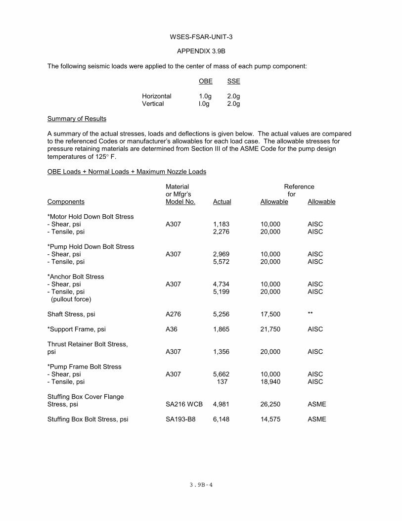
The following seismic loads were applied to the center of mass of each pump component:
OBE SSE
Horizontal 1.0g 2.0gVertical l.0g 2.0g
Summary of Results
A summary of the actual stresses, loads and deflections is given below. The actual values are comparedto the referenced Codes or manufacturer’s allowables for each load case. The allowable stresses forpressure retaining materials are determined from Section III of the ASME Code for the pump designtemperatures of 125° F.
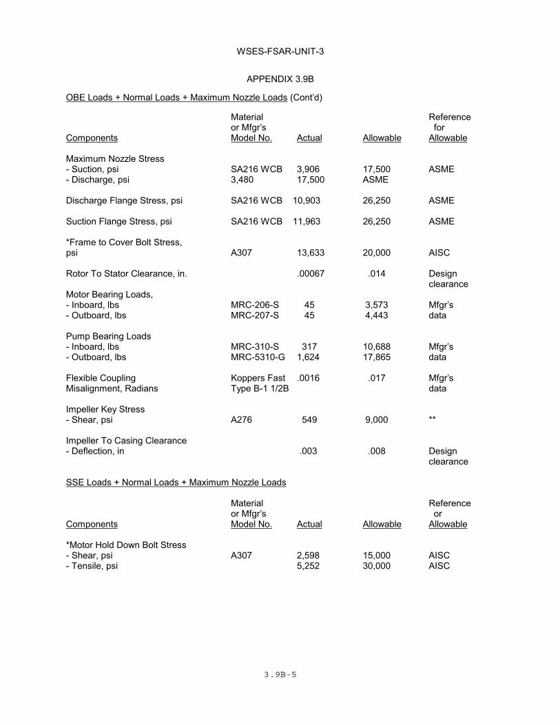
OBE Loads + Normal Loads + Maximum Nozzle Loads
Material Referenceor Mfgr’s for
Components Model No. Actual Allowable Allowable
*Motor Hold Down Bolt Stress- Shear, psi A307 1,183 10,000 AISC- Tensile, psi 2,276 20,000 AISC
*Pump Hold Down Bolt Stress- Shear, psi A307 2,969 10,000 AISC- Tensile, psi 5,572 20,000 AISC
Impeller To Casing Clearance- Deflection, in .004 .008 Design
clearance
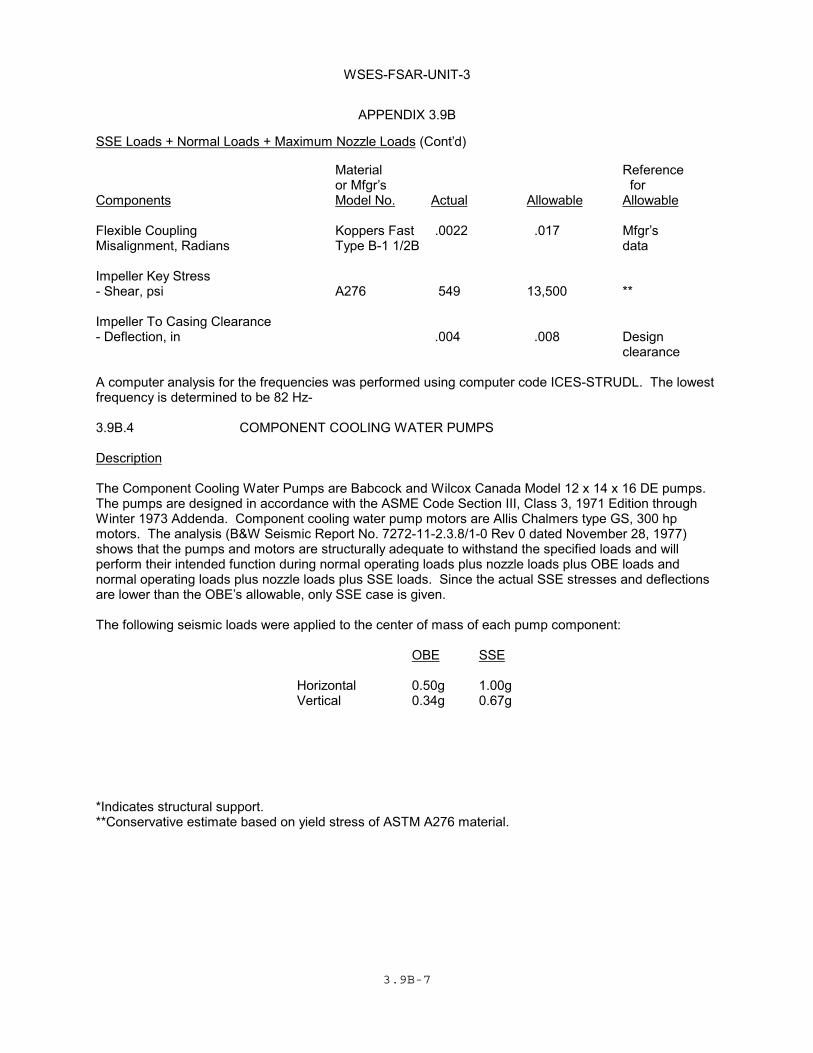
A computer analysis for the frequencies was performed using computer code ICES-STRUDL. The lowestfrequency is determined to be 82 Hz-
3.9B.4 COMPONENT COOLING WATER PUMPS
Description
The Component Cooling Water Pumps are Babcock and Wilcox Canada Model 12 x 14 x 16 DE pumps.The pumps are designed in accordance with the ASME Code Section III, Class 3, 1971 Edition throughWinter 1973 Addenda. Component cooling water pump motors are Allis Chalmers type GS, 300 hpmotors. The analysis (B&W Seismic Report No. 7272-11-2.3.8/1-0 Rev 0 dated November 28, 1977)shows that the pumps and motors are structurally adequate to withstand the specified loads and willperform their intended function during normal operating loads plus nozzle loads plus OBE loads andnormal operating loads plus nozzle loads plus SSE loads. Since the actual SSE stresses and deflectionsare lower than the OBE’s allowable, only SSE case is given.
The following seismic loads were applied to the center of mass of each pump component:
OBE SSE
Horizontal 0.50g 1.00gVertical 0.34g 0.67g
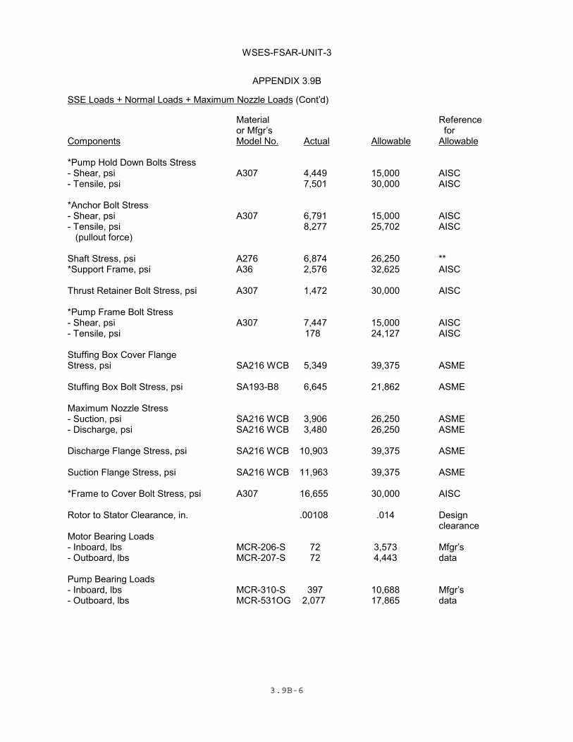
*Indicates structural support.**Conservative estimate based on yield stress of ASTM A276 material.
WSES-FSAR-UNIT-3
3.9B-8
APPENDIX 3.9B
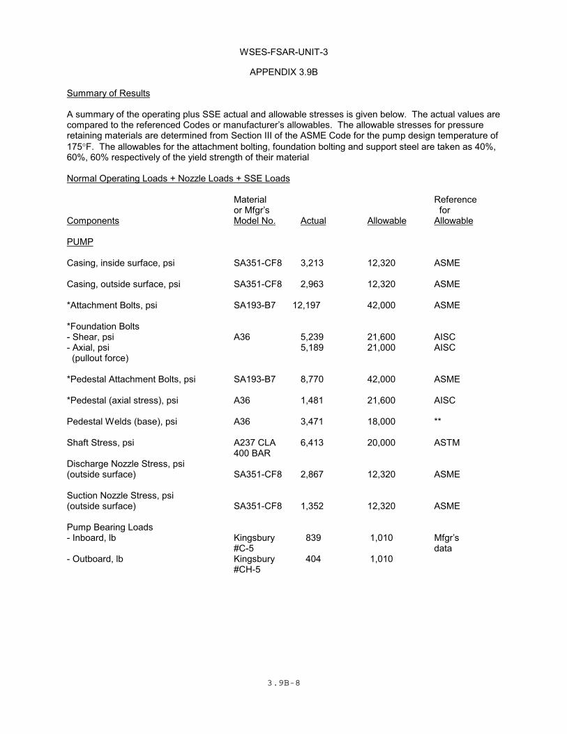
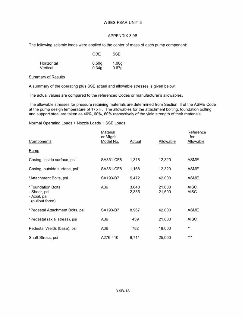
Summary of Results
A summary of the operating plus SSE actual and allowable stresses is given below. The actual values arecompared to the referenced Codes or manufacturer’s allowables. The allowable stresses for pressureretaining materials are determined from Section III of the ASME Code for the pump design temperature of175°F. The allowables for the attachment bolting, foundation bolting and support steel are taken as 40%,60%, 60% respectively of the yield strength of their material
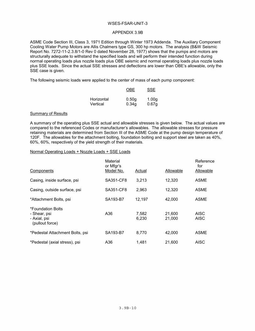
ASME Code Section III, Class 3, 1971 Edition through Winter 1973 Addenda. The Auxiliary ComponentCooling Water Pump Motors are Allis Chalmers type GS, 300 hp motors. The analysis (B&W SeismicReport No. 7272-11-2.3.8/1-0 Rev 0 dated November 28, 1977) shows that the pumps and motors arestructurally adequate to withstand the specified loads and will perform their intended function duringnormal operating loads plus nozzle loads plus OBE seismic and normal operating loads plus nozzle loadsplus SSE loads. Since the actual SSE stresses and deflections are lower than OBE’s allowable, only theSSE case is given.
The following seismic loads were applied to the center of mass of each pump component:
OBE SSE
Horizontal 0.50g 1.00gVertical 0.34g 0.67g
Summary of Results
A summary of the operating plus SSE actual and allowable stresses is given below. The actual values arecompared to the referenced Codes or manufacturer’s allowables. The allowable stresses for pressureretaining materials are determined from Section III of the ASME Code at the pump design temperature of120F. The allowables for the attachment bolting, foundation bolting and support steel are taken as 40%,60%, 60%, respectively of the yield strength of their materials.
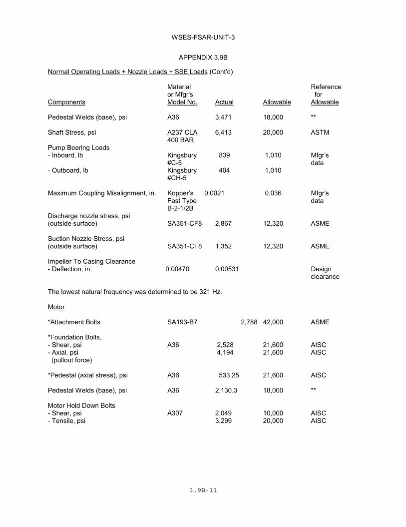
Motor Hold Down Bolts- Shear, psi A307 2,049 10,000 AISC- Tensile, psi 3,299 20,000 AISC
WSES-FSAR-UNIT-3
3.9B-12 Revision 11-B (06/02)
APPENDIX 3.9B
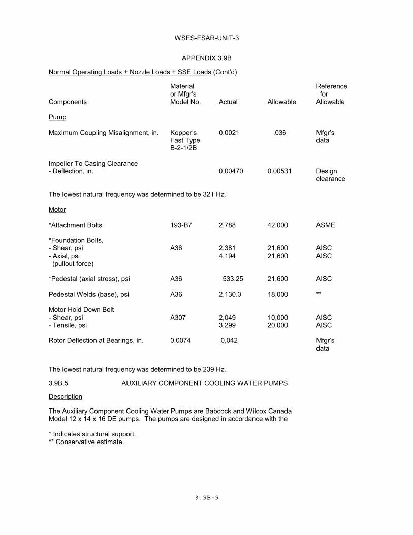
Normal Operating Loads + Nozzle Loads + SSE Loads (Cont'd)
Material Referenceor Mfgr's for
Components Model No. Actual Allowable Allowable
Rotor Deflection at Bearings, in. 0.0074 0.042 Mfgr'sdata
The lowest natural frequency was determined to be 239 Hz.
3.9B.6 EMERGENCY FEEDWATER PUMPS
Description
� (DRN 01-3697)
The Emergency Feedwater Pumps are Bingham-Willamette Ltd Models 3 x 4 x 9E MSD 7 stage and 3 x 6x 9C MSD 6 stage pumps. The pumps are designed in accordance with the ASME Code Section III,Class 3, 1971 Edition through 1972 Winter Addenda, except for the pump case material, which met the1974 Edition, Summer 1975 Addenda. The drivers for the above models are General Electric motor5K811045C25 and Terry Turbine Company turbine model GS-2, respectively. The analyses (GE SeismicAnalysis Report No. 34A842770 for motors Rev 0, dated November 3, 1977, Bingham Willamette ReportNo. 230223 for Motor Driven Pumps Rev 0, dated March 12, 1970, Bingham Willamette Report No.230225 for Turbine Driven Pump Rev 2 dated March 3, 1977, and Seismic analysis by Keith FeibuschEngineering Company for the Turbine dated February 1973) shows that the pumps, motors and turbineare structurally adequate to withstand the specified seismic conditions without loss of function.� (DRN 01-3697)
The following seismic loads specified were applied to the center of mass of each pump component:
OBE SSE
Horizontal 0.50g 1.00gVertical 0.34g 0.67g
Natural frequencies (Hz) for the motor driven pumps are as follows:
Item X-direction Y-direction Z-direction
Pump 82.2 299.0 44.1
Driver 146.0 277.0 77.3
* Indicates structural support.
** Conservative estimate.
WSES-FSAR-UNIT-3
3.9B-13
APPENDIX 3.9B
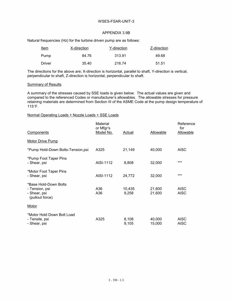
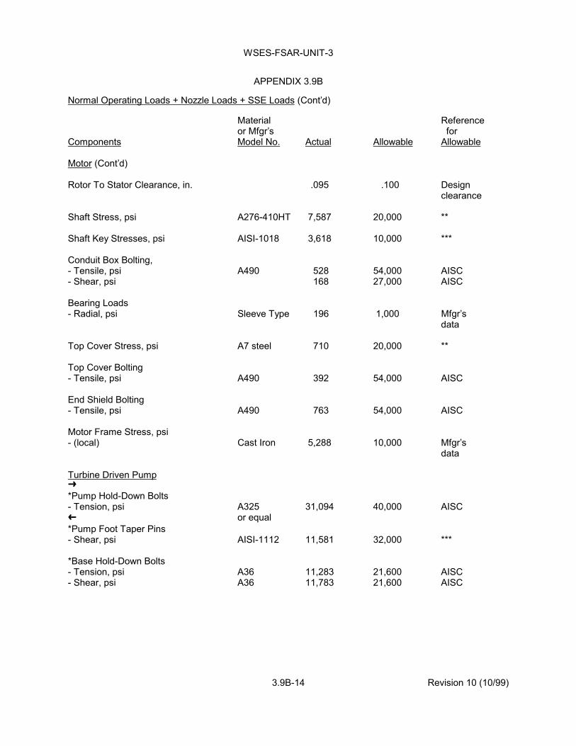
Natural frequencies (Hz) for the turbine driven pump are as follows:
Item X-direction Y-direction Z-direction
Pump 84.76 313.91 49.68
Driver 35.40 216.74 51.51
The directions for the above are; X-direction is horizontal, parallel to shaft, Y-direction is vertical,perpendicular to shaft, Z-direction is horizontal, perpendicular to shaft.
Summary of Results
A summary of the stresses caused by SSE loads is given below. The actual values are given andcompared to the referenced Codes or manufacturer’s allowables. The allowable stresses for pressureretaining materials are determined from Section III of the ASME Code at the pump design temperature of115°F.
Baseplate Connection to Concrete (pullout force) 0.2
Baseplate Connection to Concrete (anchor bolt, shear) 0.6
WSES-FSAR-UNIT-3
3.9B-16 Revision 309 (06/16)
APPENDIX 3.9B
Actual Piping(1) Maximum Loads Nozzle Loads Calculated By Pump Mfg'r Maximum Nozzle Loads Force Moment Force Moment Axis (lb) (ft-lb) (lb) ft-lb) (LBDCR 15-006, R309)
Motor Driven Pumps (material: SA-487 CA6NM ref for max loads: Seismic Analysis Report No. 230225) Suction Discharge Turbine Driven Pump (material: SA-487 CA6NM ref for max loads: Seismic Analysis Report No. 230223) Suction Discharge
(1) The actual piping loads are for information only and should not be used as a reference
for the current loadings on the pumps. See the current pipe stress analysis calculations for the current loadings and qualifications.
(LBDCR 15-006, R309)
Pump A Pump B Pump A Pump B
X 108 79 301 134 1,100 1,250 Y 219 139 294 56 1,200 1,250 Z 92 54 256 124 1,100 1,350
X 346 341 986 1,103 800 700 Y 561 499 687 933 850 700 Z 165 271 601 409 800 750
X 142 344 1,600 2,700 Y 564 440 1,700 2,700 Z 152 285 1,600 2,900 X 209 594 800 700 Y 666 275 850 700 Z 727 210 800 750
WSES-FSAR-UNIT-3
3.9B-17
APPENDIX 3.9B
A computer analysis for the frequencies and stresses was performed using the SANDEComputer Program.
* Indicates structural support.
** Conservative estimate based on yield stress of ASTM 276, A-7 materials.
*** Machinery Handbook 21st Edition.
**** The seismic calculation for the emergency feedwater pump turbine uses the criteria ofhorizontal and vertical seismic forces of 3.0g and 1.0g, respectively.
***** Margin of Safety = allowable stress - (1)calculated stress
Small clearances between rotating and stationary parts in the pump will not present any operatingdifficulties during an earthquake. Small clearances exist at wear rings and bushings. These componentsbehave as hydrodynamic bearings and are self-centering during operation - they support the rotatingelement against any seismic inertia loads. In addition experience with pumps having very flexible rotatingelements shows that these pumps operate satisfactorily even though contact would occur at closeclearances due to the weight and flexibility of the rotating element when the pumps are idle. Therefore,these small clearances are not controlling factors during an earthquake.
The pump bearings are considered adequate because the increase in bearing load due to the seismicinertia load of the rotating element is very small compared to the hydraulic loads already existing in apump.
3.9B.7 COMPONENT COOLING WATER MAKE-UP PUMPS
Description
The Component Cooling Water Make-Up Pumps are Babcock and Wilcox Canada Model 3 x 4 x 14 DLPumps. The pumps are designed in accordance with the ASME Code Section III, Class 3, 1971 Editionthrough Winter 1973 Addenda. The motors are Allis Chalmers Type RG 40 hp motors. The analysis(B&W Seismic Analysis Report No 7272-12-2.3.8/1-0 Rev A dated 3-29-78) shows that the pumps andmotors are structurally adequate to withstand the specified loads and will perform its intended functionduring normal operating loads plus nozzle loads plus OBE loads and normal operating loads plus SSEloads. Since the actual SSE stresses are lower than the OBE’s allowable, only the SSE case is given.
WSES-FSAR-UNIT-3
3.9B-18
APPENDIX 3.9B
The following seismic loads were applied to the center of mass of each pump component:
OBE SSE
Horizontal 0.50g 1.00g Vertical 0.34g 0.67g
Summary of Results
A summary of the operating plus SSE actual and allowable stresses is given below:
The actual values are compared to the referenced Codes or manufacturer’s allowables.
The allowable stresses for pressure retaining materials are determined from Section III of the ASME Codeat the pump design temperature of 175°F. The allowables for the attachment bolting, foundation boltingand support steel are taken as 40%, 60%, 60% respectively of the yield strength of their materials.
The Lube Oil Pump is Roper Model 20040. The pump is flanged mounted to the Cooper Bessemer Enginewith the inlet and discharge parts oriented horizontally. The pump is driven directly by the diesel enginecrankshaft. The analysis (Seismic Analysis Report No. HC5-922-2 by Hissong Consultants datedSeptember 22, 1975) shows that the pump is structurally -adequate to withstand the specified operatingand seismic condition. The operability of this lube oil pump is contingent on the operation of the dieselgenerator. The operability of the pump is assured by the diesel generator qualification program describedin Subsection 8.3.1.1.2.13.k.
3.9B.9 DIESEL ENGINE DRIVEN JACKET WATER PUMP
Description
The Jacket Water Pump is Allis Chalmers Model C16. The pump is flange mounted to Cooper Bessemerequipment with the impeller mounted on shaft. The pump is driven by the diesel engine crankshaft. Theanalysis (Seismic Analysis Report No. HC6-106 by Hissong Consultants dated January 6, 1976) showsthat the pump is structurally adequate to withstand the specified operating and seismic condition. Theoperability of this pump is contingent on the operation of the diesel generator. The operability of the pumpis assured by the diesel generator qualification program described in Subsection 8.3.1.1.2.13.k.


![[XLS] · Web view* extracted from ASME International Steam Tables, 6th Edition Enviromental Factor Sf Radial Stress Tangential Stress Axial Stress Steady-State Drag Force/Unit Steady-State](https://static.documents.pub/doc/80x56/5ac81bc07f8b9acb688c32e5/xls-view-extracted-from-asme-international-steam-tables-6th-edition-enviromental.jpg)


