Transport in Porous Media 32: 117–137, 1998. c 1998Kluwer Academic Publish ers. Printed in the Netherland s. 117 Gas Flow in Porous Media with Klinkenberg Effects YU-SHU WU, KARSTEN PRUESS and PETER PERSOFF Earth Sciences Division, Lawrence Berkeley National Laboratory , Berkeley , C A 94720, U.S.A. (Received: 22 September 1997; in final form: 23 February 1998) Abstract. Gas flow in por ousmedia dif fer s from liquidflow because of thelargegas compre ssibili ty and pressure-dependent effective permeability. The latter effect, named after Klinkenberg, may have significant impact on gas flow behavior, especially in low permeability media, but it has been ignored in most of the previous studies because of the mathematical difficulty in handling the additional nonlinear term in the gas flow governing equation. This paper presents a set of new analytical solutions developed for analyzing steady-state and transient gas flow through porous media including Klinkenberg effects. The analytical solutions are obtained using a new form of gas flow gov erningequation that incorp oratesthe Klink enber g effe ct. Additio nal analy tical solutio ns for one-, two- andthree- dimens ional gas flo w in por ous media cou ld be rea dil y der iv ed by the foll owing solution procedures in this paper. Furthermore, the validity of the conventional assumption used for linearizing the gas flow equation has been examined. A generally applicable procedure has been developed for accurate evaluation of the analytical solutions which use a linearized diffusivity for transient gas flow. As application examples, the new analytical solutions have been used to verify numerical solutions, and to design new laboratory and field testing techniques to determine the Klinkenberg parameters. The proposed laboratory analysis method is also used to analyze data from steady-state flow tests of three core plugs from The Geysers geothermal field. We show that this new approach and the traditional method of Klinkenberg yield similar results of Klinkenberg constants for the laboratory tests; however, the new method allows one to analyze data from both transient and steady-state tests in various flow geometries. Key words: gas flow, Klinkenberg effect, Klinkenberg constant, pneumatic analysis, unsaturated- zone flow, air venting, air permeability tests. Notation Roman Lett ers a lumped parameter in (3.5), A cross-section area, m 2 , b Klinkenberg coefficient, Pa, ddepth to well screen top, m, g gravity vector, m/s 2 , h formation thickness, m, Hlumped parameter in (3.5), Klumped parameter in (3.5), k a averaged gas permeability, m 2 , k g effective gas permeability, m 2 , k ∞ absolute permeability, m 2 , k r,∞ Klinkenberg permeability of low permeability layer in r-direction, m 2 , kz,∞ Klinkenberg permeability of low permeability layer in z-direction, m 2 , k ∞ Klinkenberg permeability of low permeability layer, m 2 ,
Transcript
8/11/2019 Wu Gas Flow in Porous Media With Klinkenberg Effects
c 1998 Kluwer Academic Publishers. Printed in the Netherlands. 117
Gas Flow in Porous Media with Klinkenberg Effects
YU-SHU WU, KARSTEN PRUESS and PETER PERSOFF Earth Sciences Division, Lawrence Berkeley National Laboratory, Berkeley, CA 94720, U.S.A.
(Received: 22 September 1997; in final form: 23 February 1998)
Abstract. Gas flow in porousmedia differs from liquidflow because of thelargegas compressibility
and pressure-dependent effective permeability. The latter effect, named after Klinkenberg, may
have significant impact on gas flow behavior, especially in low permeability media, but it has been
ignored in most of the previous studies because of the mathematical difficulty in handling the
additional nonlinear term in the gas flow governing equation. This paper presents a set of newanalytical solutions developed for analyzing steady-state and transient gas flow through porous
media including Klinkenberg effects. The analytical solutions are obtained using a new form of gas
flow governingequation that incorporatesthe Klinkenberg effect. Additional analytical solutions for
one-, two- andthree-dimensional gas flow in porous media could be readily derived by the following
solution procedures in this paper. Furthermore, the validity of the conventional assumption used for
linearizing the gas flow equation has been examined. A generally applicable procedure has been
developed for accurate evaluation of the analytical solutions which use a linearized diffusivity for
transient gas flow. As application examples, the new analytical solutions have been used to verify
numerical solutions, and to design new laboratory and field testing techniques to determine the
Klinkenberg parameters. The proposed laboratory analysis method is also used to analyze data
from steady-state flow tests of three core plugs from The Geysers geothermal field. We show that
this new approach and the traditional method of Klinkenberg yield similar results of Klinkenberg
constants for the laboratory tests; however, the new method allows one to analyze data from both
transient and steady-state tests in various flow geometries.
GAS FLOW IN POROUS MEDIA WITH KLINKENBERG EFFECTS 119
One focus of current research in the fields of unsaturated-zone hydrology andsoil physics is to develop economically feasible remediation schemes to clean up
contamination in shallow aquifers. Typical contaminants in unsaturated zones are
volatile organic chemicals (VOCs) and non-aqueous phase liquids (NAPLs) which
have been spilled from leaking storage tanks or pipelines. Once these contaminants
enter the subsurface, it is very difficult to remove them because of strong capillary and
chemical forces between these contaminants and the soil particles, which is compli-
cated by the heterogeneous nature of soils. Among currently used in situ remediation
techniques, soil–vapor extraction and air sparging have provento be very efficient and
cost-effective methods for the removal of VOCs or NAPLs from unsaturated soils.
The successful application of these techniques depends on a thorough understanding
of gas flow dynamics and site conditions. As a result, many analytical solutions
(Johnson et al., 1990; McWhorter, 1990; Baehr and Hult, 1991; Shan et al., 1992;
Baehr and Joss, 1995, and Shan, 1995) and numerical models (Weeks, 1978; Wilson
et al., 1987; Baehr et al., 1989; Mendoza and Frind, 1990; Pruess 1991; Falta et al.,
1992; Huyakorn et al., 1994; Panday et al., 1995) have been developed for analyzing
gas flow in the unsaturated zone.
The systematic investigation of gas flow in porous media was pioneered in the
petroleum industry for the development of natural gas reservoirs (Muskat, 1946). The
use of gas flow models has been a standard technique in the petroleum industry for
estimating gas permeability and other reservoir parameters in natural gas production
(Dake, 1978; and Ikoku, 1984). There exists a considerable amount of studies on
theory and application of isothermal flow of gases through porous media in the
petroleum literature. The earliest attempt to solve gas flow problems used the methodof successions of steady states proposed by Muskat (1946). Approximate analytical
solutions (Katz etal., 1959) were then obtained by linearizing the flow equation for an
ideal gas to yield a diffusion-type equation. Such solutions were found to be of limited
general use because of the assumption introduced to simplify the gas properties and
the flow equation. The reasons are that, in general, gas flow in deep pressurized gas
reservoirs does not follow the ideal gas law, and the variations of pressure around
gas production wells are too large to use constant properties. It was not until the mid
sixties that more reliable mathematical solutions were developed using a numerical
method (Russell et al., 1966) and introducing a real gas pseudo-pressure function
(Al-Hussainy et al., 1966).
In recent years, hydrologists and soil scientists have applied similar techniques
to conduct soil characterization studies by pneumatic testing of air flow proper-
ties. Pneumatic test analysis has become an important methodology in determining
formation properties of two-phase unsaturated-zone flow in a proposed repository
of high-level radionuclear waste (Ahlers et al., 1995). Because the ideal gas law
is a better approximation to the near surface air flow than in deep gas reservoirs
and also the pressure changes in the unsaturated zone are generally small, the simple
linearization using an ambient, averaged gas pressure in evaluating the gas diffusivity
term in the flow equation may be suitable for many unsaturated-zone applications.
8/11/2019 Wu Gas Flow in Porous Media With Klinkenberg Effects
While the numerical models developed can be used to perform rigorous modelingstudies of gas flow under complex conditions, analytical solutions continue to provide
a simple tool to determine gas flow properties. Despite the progress made so far in
our understanding of porous medium gas flow, one important aspect, the Klinkenberg
effect (Klinkenberg, 1941), has been ignored in most studies. Even though efforts
have been made to estimate errors introduced by neglecting the Klinkenberg effect
(Baehr and Hult, 1991), only a few studies address this phenomenon explicitly. Gas
flows in porous media differently from liquid; first, because gas is highly compress-
ible, and second, because of the Klinkenberg effect. The Klinkenberg effect may
have significant impact on gas flow behavior, especially in low permeability media.
Some recent laboratory studies (Reda, 1987; Persoff and Hulen, 1996) concluded
that the Klinkenberg effect is important in the low permeability formations studied
and cannot be ignored.
According to Klinkenberg (1941), effective gas permeability at a finite pressure
is given by
kg = k∞
1 +
b
P
, (1.1)
where k∞ is the absolute, gas-phase permeability under very large gas-phase pressure
at which condition the Klinkenberg effects are negligible; and b is the Klinkenberg
factor, dependent on the pore structure of the medium and temperature for a given
gas.
Physically, Klinkenberg effects are significant in any situation where the mean
free path of gas molecules in porous media approaches the pore dimension, i.e.when significant molecular collisions are with the pore wall rather than with other
gas molecules. Gas permeability is then enhanced by ‘slip flow’. Therefore, it has
been expected that Klinkenberg effect is the greatest in fine-grained, lower perme-
ability porous media. Jones (1972) found that b generally decreases with increasing
permeability according to
b ∝ k−0.36∞ , (1.2)
based on a study using 100 cores ranging in permeability from 0.01 to 1000 md.
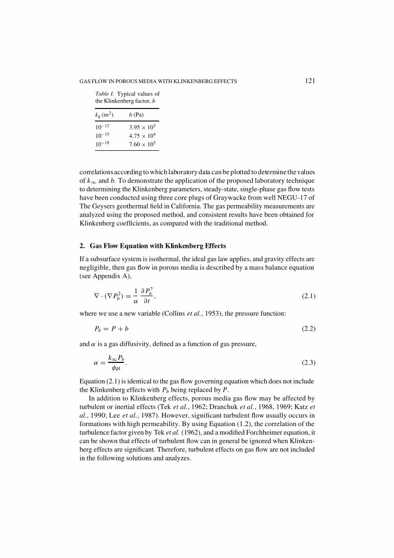
Typical values of b may be estimated as listed in Table I.
This paper presents a set of analytical solutions developed to analyze steady-
state and transient gas flow through porous media with Klinkenberg effects. A newvariable (pressure function) is used to simplify the gas flow governing differential
equation with the Klinkenberg effect. In term of the new variable, the gas flow
equation has the same form as that without including the Klinkenberg effect under the
same linearization assumption. As a result, many one-, two- and three-dimensional
gas flow solutions can be readily derived by analogy to non-Klinkenberg gas flow,
slightly compressible single-phase liquid flow or heat conduction problems.
As examples of application, the analytical solutions have been used to verify
the numerical solutions for simulating Klinkenberg effects and to provide linear
8/11/2019 Wu Gas Flow in Porous Media With Klinkenberg Effects
GAS FLOW IN POROUS MEDIA WITH KLINKENBERG EFFECTS 121
Table I. Typical values of
the Klinkenberg factor, b
kg (m2) b (Pa)
10−12 3.95 × 10³
10−15 4.75 × 10⁴
10−18 7.60 × 10⁵
correlations according to which laboratory data can be plotted to determine the values
of k∞ and b. To demonstrate the application of the proposed laboratory technique
to determining the Klinkenberg parameters, steady-state, single-phase gas flow tests
have been conducted using three core plugs of Graywacke from well NEGU-17 of The Geysers geothermal field in California. The gas permeability measurements are
analyzed using the proposed method, and consistent results have been obtained for
Klinkenberg coefficients, as compared with the traditional method.
2. Gas Flow Equation with Klinkenberg Effects
If a subsurface system is isothermal, the ideal gas law applies, and gravity effects are
negligible, then gas flow in porous media is described by a mass balance equation
(see Appendix A),
∇ · (∇ P 2b ) = 1α
∂P 2
b
∂t , (2.1)
where we use a new variable (Collins et al., 1953), the pressure function:
P b = P + b (2.2)
and α is a gas diffusivity, defined as a function of gas pressure,
α =k∞P b
φµ. (2.3)
Equation (2.1) is identical to the gas flow governing equation which does not include
the Klinkenberg effects with P b being replaced by P.In addition to Klinkenberg effects, porous media gas flow may be affected by
turbulent or inertial effects (Tek et al., 1962; Dranchuk et al., 1968, 1969; Katz et
al., 1990; Lee et al., 1987). However, significant turbulent flow usually occurs in
formations with high permeability. By using Equation (1.2), the correlation of the
turbulence factor given by Tek et al. (1962), and a modified Forchheimer equation, it
can be shown that effects of turbulent flow can in general be ignored when Klinken-
berg effects are significant. Therefore, turbulent effects on gas flow are not included
in the following solutions and analyzes.
8/11/2019 Wu Gas Flow in Porous Media With Klinkenberg Effects
The gas flow Equation (2.1) is a nonlinear partial differential equation with respect
to P 2b because of the diffusivity term α, (2.3), which is a function of pressure. In
general, the gas flow governing Equation (2.1) needs to be solved by a numerical
method. However, it is possible to obtain certain analytical solutions as proven in the
following flow conditions.
3.1. steady-state solutions
Under steady-state flow conditions, Equation (2.1) becomes linear and many ana-
lytical solutions can be directly derived using solutions from corresponding slightly
compressible fluid flow or heat conduction problems. Two examples are given in thissection to demonstrate solution procedures. The first solution is needed in Section 5
for application, and the second has applicability to a field problem.
3.1.1. Linear Flow
Under one-dimensional, linear, horizontal and steady-state flow conditions, Equation
(2.1) can be simplified as
∂
∂x
k∞β(P + b)
µ
∂P
∂x
= 0. (3.1)
The boundary conditions are: at the inlet (x = 0), a constant mass injection rate qm
per unit cross-sectional area is imposed, and at the outlet (x = L), the gas pressure
is kept constant. Then, a steady-state solution can be written as follows:
P(x) = −b +
b2 + P 2L + 2bP L + 2qmµ(L − x)/k∞β. (3.2)
3.1.2. Two-Dimensional (r-z) Axisymmetric Flow
The second example will demonstrate how to derive a new analytical solution with
Klinkenberg effects using existing non-Klinkenberg gas flow solutions. The 2-D
(radial and vertical), steady-state flow problem was described in detail by Baehr and
Joss (1995). When Klinkenberg effects are included, the flow equation becomes
kr,∞
∂ 2
∂r2 + kr,∞
1
r
∂
∂r+ kz,∞
∂ 2
∂z2 = 0, (3.3)
where = (P +b)2, and kr,∞ and kz,∞ are the Klinkenberg permeabilities in r- and
z- directions, respectively, which are different for an anisotropic system.
The problem concerns airflow to or from a partially penetrating well in an unsat-
urated zone that is separated from the atmosphere by a low-permeability, horizontal
8/11/2019 Wu Gas Flow in Porous Media With Klinkenberg Effects
GAS FLOW IN POROUS MEDIA WITH KLINKENBERG EFFECTS 123
layer on the top. At the interface (z = 0) between the unsaturated zone and the toplow-permeability layer, the continuity in pressure and mass flux requires
kz,∞
∂
∂z=
k∞
L ( − atm ) for r > rw, z = 0, (3.4)
where atm = (P atm+b)2, k∞ and L are the Klinkenberg permeability and thickness
of the top low-permeability layer. The other boundary conditions are the same as de-
scribed by Baehr and Joss (1995), except that the boundary conditions are expressed
in terms of . Then, a steady-state solution for this problem can be derived for gas
pressure distribution in the r-z system using the solution of Baehr and Joss (1995) as
(r, z) = atm
+ K ∞
n=1
αn
cosλn(L − z)
L K
0λnr
aL , (3.5)
where
K =2H µQmaL
π kr,∞(l − d)rwβ, a =
kr,∞
kz,∞
1/2
, H =(k∞L)
(kz,∞L),
and
αn =sin[λn(L − d)/L] − sin[λn(L − l)/L]
λ2nK1(λnrw/aL)(H + sin2 λn)
.
Here functions K0 and K1 are the zero-order and first-order modified Bessel functions
of the second kind, respectively, and λn(n = 1, 2, 3, . . . ) are the roots of the equation:
tan(λn) =H
λn
. (3.6)
3.2. transient solutions
Equation (2.1) may be linearized using the conventional approach for transient gas
flow analysis, i.e. set
α =k∞P b
φµ≈
k∞ P̄ b
φµ, (3.7)
where ¯P b =
¯P +b, is a function of average gas pressure,
¯P , and istreated as a constant.With the approximation of (3.7), Equation (2.1) becomes linear with respect to P 2b ,
and many analytical solutions can be obtained by analogy with heat conduction
problems (Carslaw and Jaeger, 1959) or slightly compressible flow problems, as
demonstrated in the following.
8/11/2019 Wu Gas Flow in Porous Media With Klinkenberg Effects
GAS FLOW IN POROUS MEDIA WITH KLINKENBERG EFFECTS 125
4. Evaluation of Analytical Solutions
The steady-state solutions derived above are exact solutions, and can be directly
applied to analyzing gas flow under steady-state flow conditions. However, the
transient solutions of gas flow provided in Section 3 are approximate solutions
because they assume a constant gas diffusivity, Equation (3.7), to linearize the gas
flow Equation (2.1). Such solutions, though widely used in the analysis of transient
gas flow in unsaturated zones (Weeks, 1978; and Shan, 1995), need to be further
investigated for the validity of the linearization assumption and for the conditions
under which these solutions apply. In the petroleum literature, it has been found that
in many situations, the linearization assumption is inappropriate when applied to the
flow of a real gas in reservoirs (Dake, 1978; Ikoku, 1984; Al-Hussainy et al., 1966;
and Russell et al., 1966). This may be due to the high pressure in a gas reservoir.When applied to the near surface air flow analysis, the same linearization procedure
may give reasonable accuracy for gas flow in unsaturated zones due to small (a
few percent) surface atmospheric pressure changes (Kidder, 1957). Nevertheless, the
applicability of such a linearization approximation to any particular problem should
be critically examined.
The applicability of the linearized gas flow solutions to different situations de-
pends mainly on how well an averaged formation pressure can be used to obtain
a representative gas diffusivity term in (3.7) in the pressure disturbed zone. The
conventional treatment, when Klinkenberg effects are ignored, is
P̄ ≈ P i, (4.1)
where P i is the initial, constant gas pressure of the system. This scheme may provide
reasonable accuracy for certain pneumatic analysis (Shan, 1992) when the overall
pressure changes or perturbations are small relative to initial pressure values of
the system. However, using (4.1) to evaluate the diffusivity will introduce a large
error when gas pressure changes are significant, such as in air sparging opera-
tions. We propose to use a history-dependent, averaged pressure within the pressure
changed (disturbed) domain instead of a constant diffusivity, evaluated using (4.1).
The history-dependent averaged pressure is defined as:
P̄ ≈ Aj P j
Aj
, (4.2)
where Aj is a controlled area at the geometric center of which the pressure was P j
at the immediate previous time when the solution was calculated. The summation,Aj , , is done over all Aj where pressure increases (or decreases) occurred at
the previous time value. P j is always evaluated analytically at point j, based on the
previous estimated, constant diffusivity.
The reasoning for the proposed scheme is that the diffusivity of (3.7) may be
better approximated when using an averaged, history-dependent pressure of (4.2).
Otherwise, if (4.1) is used throughout in the solution in evaluating the diffusivity
8/11/2019 Wu Gas Flow in Porous Media With Klinkenberg Effects
term, it remains constant. This may introduce significant errors to the solution, inparticular, at late times when pressures and their distributions in the system are very
different from the initial condition.
To demonstrate the proposed scheme for better estimation of the nonlinear dif-
fusivity term in the gas flow equations, we present the following comparison study
using a numerical model. A numerical code for multiphase flow, TOUGH2 (Pruess,
1991), is used here to examine the approximate transient gas flow solution. The
TOUGH2 code has been verified extensively for its accuracy in simulating gas flow
in porous media (Pruess et al., 1996). Verification examples for gas flow with the
Klinkenberg effect are provided in the next section. The test problem concerns single-
phase isothermal transient gas flow in a radially infinite systemwith constant gas mass
injection rate through a line source.
The parameters used for this comparison study are: porosity φ = 0.3; perme-
GAS FLOW IN POROUS MEDIA WITH KLINKENBERG EFFECTS 127
with the numerical solution. However, as the injection rate increases (Qm,2 = 1 ×10⁻⁴ kg/s m2), the gas pressure increases significantly. The analytical solution, with
P i as the averaged system pressure (Constant Diffusivity), gives poor accuracy, as
shown in Figure 1. However under the same injection rate, the proposed scheme for
evaluating the nonlinear diffusivity (Variable Diffusivity) using a history-dependent
averaged pressure (4.2) results in excellent agreement with the numerical solution.
Constant-diffusivity solutions give larger errors with larger injection rate in all the
cases when compared with numerical solutions. Numerical tests for one-dimensional
radial and linear flow problems indicate that the new scheme always results in more
accurate solutions than the constant-diffusivity method, when compared with the
numerical solutions (Wu et al., 1996).
5. Application
In this section, several application examples will be given for the analytical solutions
derived in Section 3. The application problems include: (1) checking the numerical
scheme; (2) laboratory determination of Klinkenberg coefficients; (3) transient well
tests; and (4) laboratory test analysis.
5.1. examination of numerical scheme
5.1.1. Steady-State Flow
This is to examine the accuracy of the TOUGH2 formulation in simulating porous
medium gas flow with the Klinkenberg effect. The problem concerns steady-state
gas flow across a linear rock column 10 m long. The system contains single-phase
gas at isothermal condition, and a constant gas mass injection rate is imposed at the
inlet of the column. The outlet end of the rock column is kept at a constant pressure.
Eventually, the system will reach steady state.
The formation and Klinkenberg properties were selected from a laboratory study
of the welded tuff at Yucca Mountain (Reda, 1987). The parameters used are: porosity
Figure 2. Comparison of the analytical and the numerical solutions for steady-state gas flow
in a finite linear system.
5.1.2. Transient Flow
This is to examine the capability of the TOUGH2 formulation in simulating transientgas flow with the Klinkenberg effects. The problem concerns gas injection into a
well in a large horizontal, uniform, and isothermal formation. A constant gas mass
injection rate is imposed at the well, and the initial pressure is uniform throughout
the formation.
The parameters used are porosity φ = 0.3; permeability k∞ = 1 × 10⁻¹⁵ m2;
Klinkenberg coefficient b = 4.75 × 10⁴ Pa; The air mass injection rate Qm =
1 × 10⁻⁶ kg/s; the initial formation pressure P i = 1 × 10⁵ Pa; the wellbore radius,
rw = 0.1 m; the formation thickness, h = 1 m; and µ and T are the same as in the
steady-state flow case above.
A comparison of the pressure profiles along the radial direction after ten days of
injection from the TOUGH2 simulation and the analytical solution (3.12) is shown
in Figure 3. Again, excellent agreement has been obtained for the transient flow
problem.
5.2. laboratory determination of permeability and klinkenberg
coefficient
The traditional method used in laboratory determination of the permeability and the
Klinkenberg coefficient is using a plot of averaged gas permeability ka vs. inverse
8/11/2019 Wu Gas Flow in Porous Media With Klinkenberg Effects
GAS FLOW IN POROUS MEDIA WITH KLINKENBERG EFFECTS 131
b = 4.77× 10⁵
Pa. The actual values are k∞ = 1.0× 10⁻¹⁵
m2
and b = 4.75× 10⁵
,and this indicates the proposed well test method is very accurate in determining these
two Klinkenberg parameters.
5.4. laboratory test analysis
5.4.1. Materials and Methods
Steady-state gas flow experiments were conducted to test the model and to evaluate
k∞ and b. Two rock core samples were obtained from well NEGU-17, in The Geysers
geothermal field. Three cylindrical plugs, 15 mm in diameter were taken from the
samples using a diamond core bit, and the cylinder ends were machined flat and
parallel with lengths ranging from 9 to 11 mm.The plugs were mounted into 2 in long stainless steel tubing using Castall E-205
epoxy resin. They were then dried at 60◦C for 5 days to remove all moisture. All
three sample tubes were connected to a gas inlet manifold where nitrogen gas was
applied at controlled pressures ranging from 120 to 380 kPa.
Gas exiting from the sample flowed through a 1 m long horizontally mounted
3.175 mm o.d., 0.559 mm wall clear nylon tubing. To measure the gas flow rate, a
slug of dyed water was injected into the tubing before it was connected to the sample
tube, and the displacement of the slug was used to measure the gas flow rate. By
monitoring the position of the slugs in the exit tubes, we were assured that steady
state had been reached before measuring the flow rate.
Leaks that would normally be insignificant may be significant when measuringvery low gas flows. An advantage of this experimental system is that any gas leak
upstream of the sample would not cause any error, as long as the pressure is accurately
measured. The gas flow that is to be monitored is at ambient pressure, so there is no
driving force for it to leak and escape from the measurement tube. To test whether
the technique of sealing the plugs into the stainless steel sample tube prevented gas
from leaking past the sample, a dummy plug of aluminum was sealed into a stainless
steel tube the same way and flow tested; no flow was observed.
5.4.2. Results and Data Analysis
The flow rate and pressure data are summarized in Table II. These data will be
interpreted according to the traditional Klinkenberg method of (5.1) and (5.2) and tothe new model (5.3), referred as to exact Klinkenberg analysis in this paper. In both
cases, the data of Table II are used to calculate derived quantities that are plotted as
straight lines.
In the exact Klinkenberg analysis, the calculated quantities X = (P 0 + P L)/2
and Y = qmµL/β(P 0 − P L) are summarized in Table II and are plotted in Figure 4
for the three samples. In the traditional Klinkenberg analysis, Figure 5 plots the data
calculated in Table II, and Table III presents the calculated values of k∞ and b derived
from the linear plots, as well as the correlation coefficients. The values obtained by
8/11/2019 Wu Gas Flow in Porous Media With Klinkenberg Effects
A general gas flow governing equation including the Klinkenberg effect has been
derived by introducing a new pressure variable. Based on this new form of gas
flow governing equation, a set of new analytical solutions has been developed for
analyzing steady-state and transient gas flow through porous media with Klinkenberg
effects. As an extension of this work, additional analytical solutions for one-, two-
and three-dimensional gas flow with the Klinkenberg effect can be readily derived.
These analytical solutions will find their applications in analyzing gas flow and
determining soil flow properties in the unsaturated zone or in laboratory tests where
the Klinkenberg effects cannot be ignored.
To determine the condition under which the linearized gas flow equation may
be applicable, a numerical method is used to examine the predictions from theapproximate analytical solutions for transient gas flow. It has been found that the
conventional linearization procedure of deriving gas flow equations, using an initial
gas pressure for the diffusivity term, will result in acceptable solutions when the over-
all pressure variations in the system are small. However, the linearization assumption
may introduce considerable errors when pressure changes are significantly different
from the ambient condition. In this case, we propose a new evaluation procedure
for the diffusivity term using a history-dependent averaged pressure with analytical
solutions, which will still give accurate solutions even under high pressure disturbed
conditions of the system.
In order to demonstrate their applications, the new analytical solutions have been
used to verify the numerical solutions of gas flow which include the Klinkenberg
effect. Several new laboratory and field testing techniques are derived, based on the
analytical solutions for determining the Klinkenberg parameters of porous medium
gas flow. These new laboratory and field test analysis methods are very easy to
implement and more accurate to use. One of the proposed laboratory methods has
been applied to laboratory testing results in determining absolute permeability and
Klinkenberg constants and to examination of the traditional Klinkenberg analysis.
The transient test analysis method is illustrated using a simulated well test result.
Appendix: Derivation of the Gas Flow Equation
Under isothermal conditions, gas flow in porous media is governed by a mass balance
equation,
∇ · (ρv) = −φ∂(ρ)
∂t , (A.1)
where ρ is gas density; φ is formation porosity, assumed to be constant; v is the
Darcy’s velocity of the gas phase, defined as
v = −kg
µ(∇ P − ρg), (A.2)
8/11/2019 Wu Gas Flow in Porous Media With Klinkenberg Effects
GAS FLOW IN POROUS MEDIA WITH KLINKENBERG EFFECTS 135
where µ is gas-phase viscosity; g is gravity vector; and kg is effective gas-phasepermeability, described by Equation (1.1), including the Klinkenberg effects.
The ideal gas law is here used to describe the relation between gas density and
pressure as,
ρ = βP , (A.3)
where β is a compressibility factor, defined as
β = M g/RT (A.4)
with M g being the molecular weight of the gas; R the universal gas constant; and T
constant temperature.
When gravity effects are ignored, combining Equations (A.1)–(A.3), and (1.1)will give
∇ ·
k∞β
µ(P + b)(∇ P )
= φβ
∂P
∂t . (A.5)
In terms of the new variable, P b = P +b, Equation (A.5) may be written as the form
of (2.1).
Acknowledgements
The authors are indebted to S. Finsterle and E. Sonnenthal for their critical review of
this manuscript. Thanks are also due to the anonymous reviewersof this work for theirconstructive suggestions. This work was supported in part by the Director, Office of
Civilian Radioactive Waste Management, and by the Assistant Secretary for Energy
Efficiency and Renewable Energy, Geothermal division, of the U.S. Department of
Energy, under Contract No. DE-AC03-76SF00098.
References
Ahlers, C. F., Finsterle, S., Wu, Y. S. and Bodvarsson, G. S.: 1995, Determination of pneumatic
permeability of a multi-layered system by inversion of pneumatic pressure data, Proc. of the
1995 AGU Fall Meeting, San Francisco, California.
Al-Hussainy, R. J. Ramey, and Crawford, P. B.: 1966, The flow of real gases through porous media,
J. Petrol. Technol. pp. 624–636.
Baehr, A. L. and Joss, C. J.: 1995, An updated model of induced airflow in the unsaturated zone,
Water Resour. Res. 27(10), 417–421.
Baehr, A. L., Hoag, G. E. and Marley, M. C.: 1989, Removing volatile contaminants from the
unsaturated zone by inducing advective air-phase transport, J. Contam. Hydrol. 4, 1–26.
Baehr, A. L. and Hult, M. F.: 1991, Evaluation of unsaturated zone air permeability through
pneumatic tests, Water Resour. Res. 27(10), 2605–2617.
Carslaw, H. S. and Jaeger, J. C.: 1959, Conduction of Heat in Solids, Clarendon Press, Oxford.
Collins, R. E. and Crawford, P. B.: 1953, Calculations of unsteady-state gas flow through porous
media, corrected for Klinkenberg effects, AIME Trans. 198, 339–340.
8/11/2019 Wu Gas Flow in Porous Media With Klinkenberg Effects
GAS FLOW IN POROUS MEDIA WITH KLINKENBERG EFFECTS 137
Shan, C., Falta, R. W. and Javandel, I.: 1992, Analytical solutions for steady state gas flow to a soilvapor extraction well, Water Resour. Res. 28(4), 1105–1120.
Tek, M. R., Coats, K. H. and Katz, D. L.: 1962, The effects of turbulence on flow of natural gas
through porous reservoirs, J. Petrol. Technol. AIME Trans. 222, 799–806.
Theis, C. V.: 1935, The relation between the lowering of the piezometric surface and the rate and
duration of discharge of a well using Ground-water storage, Trans. AGU , pp. 519–524.
Weeks, E. P.: 1978, Field determination of vertical permeability to air in the unsaturated zone, US
Geological Survey Professional Paper 1051.
Wilson, D. E., Montgomery, R. E. and Sheller, M. R.: 1987, A mathematical model for removing
volatile subsurface hydrocarbons miscible displacement, Water Air Soil Pollut. 33, 231–255.
Wu, Y. S., Pruess, K. and Persoff, P.: 1996, Steady and transient analytical solutions for gas flow in
porous media with Klinkenberg effects, Research Report LBNL-39499, UC-1240, Lawrence