1 GENERAL INTRODUCTION With a span of 460m between springing points, the Wuxia Yangtze River Bridge in Wushan, China is the longest single span concrete filled steel tublar arch bridge in the world when completed in 2005. The geometry of the Wu Gorge, with relatively sound rock at the upper regions of the embankments to support the thrust of the arch, was ideal for the arch. The steep banks almost dictated the application of the cable crane method, whereby the arch could be constructed in cable crane without very costly conventional centering supported from the banks of the gorge or on temporary steel arches or girders. It is a half-through concrete filled steel tubular arch bridge with a rise-span ratio of 1/3.8. The span arrangement is of 6×12m + 492m + 3×12m(shown in Fig.1). The total length of the bridge is 612.2m. The bridge width is 19m, in which 15.0m for traffic lane and 2×1.5m for walk side road as well as 2×0.5m for rails. The arch ribs are twin of CFST trusses. The axis is a catenary curve with a parameter m of 1.55. The width of a rib is 4.14m; its height of the rib varies from 7.0m in crown to 14.0m in the spring. The center distance of the two ribs is 19.7m. Fig.1: General Layout of Wuxia Yangtze River Bridge(unit:m) Wuxia Yangtze River Bridge in Wushan, China T. Mu, B. Fan and X. Zheng Design and Research Institute of Highway Planning and Surveying of Sichuan,China Y. Zheng and B. Xie Sichuan Chuanjiao Highway Project Consultation Co., Ltd., China ABSTRACTS:Wuxia Yangtze River Bridge is a half-through concrete-filled steel tubular arch bridge with a main span of 492m (net span 460m), the span of which is the longest of the same kind of bridge in the world. There are innovations and development in respect of design calculation, structure measures, pumping of concrete in the steel tube, joint design, hanging system design, durability design and of other technical fields.
Transcript
1 GENERAL INTRODUCTION
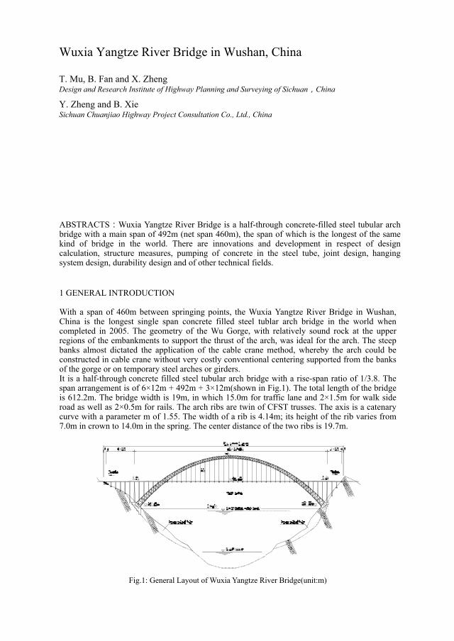
With a span of 460m between springing points, the Wuxia Yangtze River Bridge in Wushan, China is the longest single span concrete filled steel tublar arch bridge in the world when completed in 2005. The geometry of the Wu Gorge, with relatively sound rock at the upper regions of the embankments to support the thrust of the arch, was ideal for the arch. The steep banks almost dictated the application of the cable crane method, whereby the arch could be constructed in cable crane without very costly conventional centering supported from the banks of the gorge or on temporary steel arches or girders. It is a half-through concrete filled steel tubular arch bridge with a rise-span ratio of 1/3.8. The span arrangement is of 6×12m + 492m + 3×12m(shown in Fig.1). The total length of the bridge is 612.2m. The bridge width is 19m, in which 15.0m for traffic lane and 2×1.5m for walk side road as well as 2×0.5m for rails. The arch ribs are twin of CFST trusses. The axis is a catenary curve with a parameter m of 1.55. The width of a rib is 4.14m; its height of the rib varies from 7.0m in crown to 14.0m in the spring. The center distance of the two ribs is 19.7m.
Fig.1: General Layout of Wuxia Yangtze River Bridge(unit:m)
Wuxia Yangtze River Bridge in Wushan, China
T. Mu, B. Fan and X. Zheng Design and Research Institute of Highway Planning and Surveying of Sichuan,China
Y. Zheng and B. Xie Sichuan Chuanjiao Highway Project Consultation Co., Ltd., China
ABSTRACTS:Wuxia Yangtze River Bridge is a half-through concrete-filled steel tubular arch bridge with a main span of 492m (net span 460m), the span of which is the longest of the same kind of bridge in the world. There are innovations and development in respect of design calculation, structure measures, pumping of concrete in the steel tube, joint design, hanging system design, durability design and of other technical fields.
912 ARCH’07 – 5th International Conference on Arch Bridges
2. SUPERSTRUCTURE 2.1 Main Span 2.1.1 Arch rib and brace The arch rib of the bridge is of truss structure made of concrete-filled steel tube. The width of a rib is 4.14m; its height varies from 7.0m in crown to 14.0m in the spring. Four chord members in each rib are steel tubes Ф1220×22mm filled with C60 concrete. The vertical and the diagonal web members are made up of steel tubesФ610×12mm. The lateral bracing members of the CFST chords are also hollow steel tubes of Ф711×16mm. Between the two vertical web members at the hanger location, the cross struts are provided to strengthen the lateral connection of the arch ribs. It can be seen in Fig.2. The distance between centers of the arch ribs is 19.7m. ‘K’ shaped cross brace are set between two ribs above the level of deck and, at the arch spring below the deck, ‘米’ shaped cross brace are set. Each cross brace is a hollow steel pipe truss. One cross brace is provided between ribs at the joint between the arch ribs and the deck. There are a total of 20 cross brace in the bridge.
Fig.3: Sketch of arch rib arrangement(unit:mm)
Fig.4: Installation of arch ribs
2.1.2 Hanger The hanger is composed of 109 pieces of Φ 7mm pre-stressed steel wires sprayed with epoxy, as shown in Fig.5. To prevent corrosion, the painting system is designed as: galvanized course + epoxy course (160um) + corrosion proof grease + polythene jacket (2 layers) + foaming polyurethane + Haversian canal. The corrosion proof system has the following merits: (a) the corrosion proof course has clear protection gradients of the corrosion proof system; (b) good thermal insulation performance, with little influence by the temperature; (c) lower cost and easy maintenance.
Fig.5: Sketch of suspension rod cross sectional structure(unit:cm)
T. Mu, B. Fan, X. Zheng, Y. Zheng and B. Xie 913
At both ends of the hanger, a kind of chill mould anchorage named 0VMLZMT—109 are used. Screw for height adjustment of horizontal beam are provided at both ends of the hanger. End protection plate, protection shied and solidified grease are also provided at the upper and lower anchorage devices respectively, shown in Fig.6. Meanwhile, heat-shrinkage plastic sheath is provided at the joints of the hanger, Haversian canal jacket, and the anchorage device.
Fig. 6: Structural drawing of the anchorage(unit:cm)
In order to prevent the steel wires from corrosion, resulted from the atmosphere, rainwater and other facters, waterproof steel plates are provided at the joints of horizontal beams and the steel pipe jackets of the suspension rods. The waterproof steel plates and steel pipe jackets are welded together to ensure sealing effects, as indicated by fig.7 below:
Fig.7: Sketch of waterproof at the joints(unit:cm)
In order to prevent the short hanger from excessive displacement caused by shrinkage, creep, temperature difference, braking force and other factors that result in fatigue failure of the short hangers, longitudinal struts are provided at the short hangers of the cross struts between the ribs and sliding-plate supports are also provided on the longitudinal beam at the cross brace and short hangers, shown in Fig.8.
Fig.8: Longitudinal struts of hanger(unit:cm)
914 ARCH’07 – 5th International Conference on Arch Bridges
2.1.3 Cross beam and deck beam The cross beam, located at the end of hanger and at the column are of pre-stressed concrete composite beams, which is easier to precast on-site and install, shown in fig.9. While for the cross beam between the arch ribs are made of steel beam, which is convenient to connect with the arch ribs and simplify the structure.
Fig.9: Cross beam of hanger(unit:cm)
The deck beam is pre-stressed ‘π’ shaped beam, which is simple supported and then made it continuous. The beam is 110cm high and precasting length is 1170cm (except the beam at the expansion gap). When they are hoisted to the right position, the main reinforcement bars on the upper and lower edges of the beam are welded, then the joint concrete of 30cm is casted in-situ to form continuous beam.
Fig. 10: Typical structure of deck beam(unit:cm)
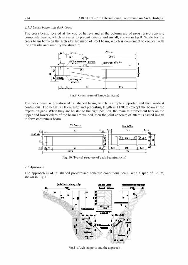
2.2 Approach The approach is of ‘π’ shaped pre-stressed concrete continuous beam, with a span of 12.0m, shown in Fig.11.
Fig.11: Arch supports and the approach
T. Mu, B. Fan, X. Zheng, Y. Zheng and B. Xie 915
2.3 Deck system The deck is of 8cm thick special shaped steel fiber reinforced concrete. At the cross beam of the hanger and the coping, more longitudinal steel meshes are provided to prevent the crack caused by the negative bending moment. The expansion joint are set at the bridge abutments on both sides and No.16 column At both sides of the bridge, river-crossing pipe lines are provided, and at the corresponding places of the bridge abutments at both sides of the riverbanks, openings are provided to allow the passing of the pipe lines of electric power, telecommunication, bridge lighting and running water. Running water pipe lines are provided at both sides of the bridge symmetrically, with diameter not bigger than 400mm.
3. SUBSTRUCTURE 3.1 Abutment and pier ‘U’ shaped bridge abutments are adopted at both sides of the riverbanks and the foundation of the bridge abutments located on the relatively intact and slightly weathered base rock, the required allowable load bearing capacity of the base rock shall not be less than 0.8Mpa. The bridge pier of the ramp bridge is designed as insitu reinforced concrete paired column with extended foundation by open excavation, as indicated by fig.11. The allowable load bearing capacity of the base rock shall not be less than 1.0Mpa.
3.2 Support of the main arch The design of arch support is of reinforced concrete, with 3 reinforced concrete cross struts provided longitudinally. The foundation of the arch support is on the steady, intact and slightly weathered base rock. The allowable load bearing capacity of the base shall not be less than 3.0Mpa, as indicated by fig.11.
4 CORROSION PROOF DESIGN
According to the latest research and comparative tests carried out on corrosion proof and mechanical capacities of the comparatively better corrosion proof materials at the present time, the arc thermal sprayed aluminum-magnesium alloy corrosion proof scheme is selected, which are considered to have relatively better corrosion-proof and mechanical capacities at the present time. The corrosion proof service life is 30 years, with Sa3 grade metal surface treatment, 160µM aluminum-magnesium sprayed coat, epoxy closing course (842) of 50µM thick, acrylic-acid polyurethane finishing course of 50µM thick.
5 ERECTION OF ARCH RIB 5.1 Segments and joints of the arch rib 5.1.1 Segments of the arch rib Each arch rib is divided into 22 segments; each is 70 to 116 tons’ weight. In order to make the transportation convenient and keep the precision of the joints, two web members are provided at the joints of the segments to reinforce the joints and fixing their shapes, making each segment into relatively independent member.
5.1.2 Joints Inner flange joints are provided between segments, and the joint flange is smaller than the main chord tube. The concrete can be delivered freely between the chord pipe and the flange as well as inside the hole of the flange, shown in fig.12.
916 ARCH’07 – 5th International Conference on Arch Bridges
Fig.12: Joints of the arch rib(unit:m)
5.1.3 Joints at crown and spring At the joints of the crown, turnbuckle joint devices are provided for instantaneous closing/assembly. The turnbuckle can be turned in and out by the screw, hence achieving adjustment of the length of the closing section and the stress of the arch ring, the elevation is shown in fig.13.
Fig.13: Closing joints at crown(unit:m)
At arch spring, hinges are provided upon the concrete-filled steel pipe columns along the axial line of the arch. After completion of installation and closing of the arch rib and proper alignment of the axial line, the chord pipes of the arch springing can then be connected to seal and fixing the arch springing, forming into a hingeless arch, as indicated by fig.14.
Fig.14: Hinge at arch spring(unit:cm)
T. Mu, B. Fan, X. Zheng, Y. Zheng and B. Xie 917
5.2 Erection of arch rib of main span 5.2.1 Erection procedure The main arch is erected by cable crane method. The hoisting equipment is made of 2 main parts, namely the hoisting system and cable stayed hanging system.
5.2.2 Hanging system The hanging system of main arch rib consists of 5 parts, i.e. hanging points, turning points, cable saddle, hanging tower, jacking anchorage beam and buckle wires. The general layout of the system is shown in fig. 15.
Fig.15: General layout of hanging system of arch rib(unit:m)
The hanging tower of the cable stayed system should have sufficient rigidity, with maximum horizontal displacement of 4.5cm at the top of the tower.
5.2.3 Hoisting system Horizontal beam is provided at the top of the hanging tower, and hoisting tower of the hoisting system is set at the top of the horizontal beam. The connection between the hoisting tower and buckling tower is of hinge connection. The tower height is about 40m. The hoisting sections is put into place and installed by cable hoist.
5.3 Concrete grouting of arch ring chord pipes In order to ensure the integrity of the concrete in the tube, the concrete is pumped into steel tube of the arch ribs in one time. 3 pumping ports are provided at each side of chord. Firstly, pumping concrete into the pipe from arch spring (pumping port No.1) until slurry comes out of the slurry outlet of No.2 pumping port; After releasing the air in the pumping pipe by regulating the related valves at No.2 grouting port, filling concrete into the pipe by the relay pumping method through No.2 pumping port until slurry comes out of the slurry outlet of No.3 pumping port. By taking the same method to pour concrete into the pipe through No.3 pumping port in relay method until slurry comes out of the slurry outlet at the top of the arch, as indicated in Fig.16.
918 ARCH’07 – 5th International Conference on Arch Bridges
Fig. 16: Indication sketch of concrete-filled steel pipe grouting of the main arch
6 MAIN ECONOMIC INDEX
After statistical research and evaluation of material consumption of the whole bridge, the main economic index of the project are given as the table follows: