UTS is an important service to the passengers and simultaneously it is revenue generating area for Indian Railways. Therefore proper maintenance of UPS for UTS is necessary to provide smooth service to passengers and for earning revenue.
CAMTECH has prepared this handbook on “UPS for UTS” with the objective of disseminating knowledge about UPS, its salient features, maintenance and trouble shooting etc.
I am sure that this handbook will be useful to field staff
in maintaining UPS in excellent condition which will improve the reliability of the Unreserved Ticketing System. CAMTECH Gwalior A.R.Tupe Date : 19.10.2012 Executive Director
PREFACE There are several applications where even temporary power supply failures cause a great deal of public inconvenience leading to large economic losses. Example of one such application is PRS/ UTS. CAMTECH has prepared this handbook on “UPS for UTS” with the objective to improve maintenance practices of UPS and to disseminate basic knowledge about UPS, its components, maintenance and trouble shooting etc. Frequently Asked Questions have also been included which will be useful for understanding the terminology of critical areas. It is clarified that this handbook does not supersede any existing provisions laid down by RDSO or Railway Board/Zonal Railways. This hand book is for guidance only and it is not a statutory document. I am sincerely thankful to EEM Directorate of RDSO/ Lucknow for guidance and approving this handbook, I am also thankful to field personnel who helped us in preparing this handbook. Technological up-gradation & learning is a continuous process. Please feel free to write to us for any addition/ modification in this handbook. CAMTECH, Gwalior Peeyoosh Gupta Date: 19.10.2012 Jt. Director Electrical
rkjh[krkjh[krkjh[krkjh[k la’kksf/kr Ik`"B la[;k la’kksf/kr Ik`"B la[;k la’kksf/kr Ik`"B la[;k la’kksf/kr Ik`"B la[;k rFkk en la[;krFkk en la[;krFkk en la[;krFkk en la[;k
fVIi.khfVIi.khfVIi.khfVIi.kh
CAMTECH/E/12-13/UPS/1.0
October, 2012 Handbook on UPS for UTS
10
ISSUE OF CORRECTION SLIPS
The correction slips to be issued in future for this handbook will be numbered as follows :
CAMTECH/E/12-13/UPS/C.S. # XX date--------- Where “XX” is the serial number of the concerned correction slip (starting from 01 onwards).
CORRECTION SLIPS ISSUED
Sr. No. Date of issue Page no. and Item no. modified
Remarks
CAMTECH/E/12-13/UPS/1.0
Handbook on UPS for UTS October, 2012
1
v/v/v/v/;k; 1;k; 1;k; 1;k; 1 CHAPTER 1
lkekU; fooj.klkekU; fooj.klkekU; fooj.klkekU; fooj.k GENERAL DESCRIPTION
1.1 ÁLrkoukÁLrkoukÁLrkoukÁLrkouk INTRODUCTION
UPS (Uninterrupted Power Supply) is used to provide uninterrupted power (continuous power) to the connected loads. In Railways there are several applications such as PRS, UTS, EDP centers etc. where even a short/ temporary power supply failure can cause a great inconvenience to public/ passengers and also may lead to financial loss to the railways.
RDSO, Lucknow has issued a technical specification for fault tolerant Uninterrupted Power Supply (UPS) system for PRS, EDP centers and other similar requirements of ON LINE UPS system vide RDSO/ PE/ SPEC/ PS/ 0023-2001 (Rev. 0), Amendment no.3 dtd.16.09.2011.
As per above specification, the UPS provided in Railways are single phase or three-phase system as indicated below for different ratings.
Category A: 1 kVA to 7.5 kVA with single-phase input and single phase output.
Category B: 7.5 kVA to 30 kVA with three phase input and single phase output.
Category C: 10 kVA and above with three phase input and three phase output.
CAMTECH/E/12-13/UPS/1.0
October, 2012 Handbook on UPS for UTS
2
Generally category ‘A’ UPS (1 kVA to 7.5 kVA with single phase input and single phase output) are provided at booking offices for Unreserved Ticketing System (UTS) for continuous power backup which has been dealt in this handbook.
An uninterrupted power supply (UPS) is a device that has an alternate source of energy (battery) that can provide power when the primary power source is temporarily disabled. The function of an UPS is to supply uninterrupted power to the critical load, such as Computers, vital alarm systems, surgical/ medical equipment and process control systems etc.
In this the rectifier accepts mains ac, converts it
into dc to feed it to the inverter as well as to charge the batteries. The inverter converts dc power into clean, stable isolated ac output which is given to the load connected at the output. In the event of mains failure, the inverter works on the battery supply and gives the uninterrupted output for a period of backup time.
Following are the some advantages of ‘ON LINE’ UPS in a system:
(i) It provides highest degree of filtering & conditioning of raw power against various input disturbance.
CAMTECH/E/12-13/UPS/1.0
Handbook on UPS for UTS October, 2012
3
(ii) It provides pure sine wave output with constant voltage and frequency all the times.
(iii) There is no switching time between input supply and battery as the inverter always lies in switch on condition.
(iv) It protects against multiple types of power disturbances such as interruption, under voltage, over voltage, surges, voltage fluctuation, frequency variation, spikes/ transients, impulsive, oscillatory wave form distortion, dc offset, harmonics, notching, noise etc.
(v) It protects against an outage.
(vi) It protects against data loss.
(vii) It protects against time and expense to recover back to where you were.
Technology – IGBT based True On-line Double conversion technology with high frequency PWM.
buiqV buiqV buiqV buiqV fo|qr vkiwfrZfo|qr vkiwfrZfo|qr vkiwfrZfo|qr vkiwfrZ Input power supply a) 160V – 280 Volts for single phase (140 V – 280 V
may be asked by indenter) b) Frequency range 50 Hz ± 8%. c) Power factor measured at input terminal should be
more than 0.8 at full load.
CAMTECH/E/12-13/UPS/1.0
October, 2012 Handbook on UPS for UTS
4
mRikfnr fo|qr vkiwfrZmRikfnr fo|qr vkiwfrZmRikfnr fo|qr vkiwfrZmRikfnr fo|qr vkiwfrZ Out put power supply
i. Voltage 230V ± 1% for single phase ii. Output frequency 50 ± 0.5 Hz (free running) iii. Output Waveform Sine wave iv. Load Power Factor May vary from 0.65 to unity v. Transient response 230V ± 5% for 0-100% load
jump and vice-versa vi. Transient recovery
time 40 ms for 0-100% load jump and vice-versa < 3% on linear load vii. Total Harmonic
Distortion < 15% on nonlinear load viii. Overall efficiency > 85% at nominal input at
0.8 pf ix. Over Load 125% for minimum 10 mins
150% for minimum 1 min x. Crest Factor Better than 3:1 xi. Type of battery Sealed Maintenance Free
Lead Acid battery xii. Back up time Minimum 2 hours at rated
full load For Category-A xiii. Environment Condition Operating
integrated system comprising of input rectifier, high frequency based PWM technique inverter using IGBT s and DSP/ Microprocessor/ Microcontroller based control electronics, static by pass switch and manual bypass switch.
The battery charger is designed such that it charges the battery in constant voltage, constant current mode at the rate of 0.1C (C is the AH capacity of the battery). It is capable to recharge the battery from discharged condition to its full capacity in 8 to 10 hrs.
To Load
Static bypass
Filter DC
AC
AC
DC
Battery
Input
AC to DC Converter
Inverter
IGBT rectifier mounted on heat sink
CAMTECH/E/12-13/UPS/1.0
October, 2012 Handbook on UPS for UTS
6
Schematic Diagram
The UPS system is able to configure in hot stand by redundant UPS with bypass. The bypass line of the primary UPS is connected to the inverter of the secondary UPS. The bypass line of the secondary UPS is connected to the bypass main source.
RECTIFIER INVERTER STATIC SWITCH
Bypass supply
Mains supply
Maintenance bypass Isolator
Bypass Isolator
Input Isolator
Output Isolator
1 + 1 PARALLEL CONTROL
BATTERY
UP
S O
UT
PU
T S
UP
PLY
1 + 1 PARALLEL CONTROL
RECTIFIER INVERTER STATIC SWITCH
Mains supply
Input Isolator
Output Isolator
Bypass supply
Maintenance bypass Isolator
Bypass Isolator
CAMTECH/E/12-13/UPS/1.0
Handbook on UPS for UTS October, 2012
7
Both the UPS use a common battery bank. At any given point of time only one UPS carries the load. In the event of failure of working UPS the load is automatically transferred to the standby UPS without causing a spurious load trip. In case both the UPS fail, the supply is transferred to the main source through the static bypass switch. There is no current sharing parallel redundant system.
The UPS system is suitable to feed all loads
connected to output which are primarily computers, printers, servers, scanners, modems etc.
The UPS system is of true double conversion with
in-built isolation transformer (copper wound). The inverter, rectifier and battery charger are IGBT based systems with IGBT modules. Components are capable of withstanding the thermal and dynamic stresses resulting from internal and external short circuits and circuit switching operations etc.
The UPS design is capable to withstand short
circuit at load without causing an adverse effect on the UPS.
CAMTECH/E/12-13/UPS/1.0
October, 2012 Handbook on UPS for UTS
8
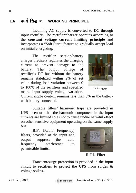
1.6 dk;Z fl)kUrdk;Z fl)kUrdk;Z fl)kUrdk;Z fl)kUr WORKING PRINCIPLE Incoming AC supply is converted to DC through
input rectifier. The rectifier/charger operates according to the constant voltage current limiting principle and incorporates a “Soft Start” feature to gradually accept load on initial energizing.
The rectifier section/battery charger precisely regulates the charging current to prevent damage to the battery. The output voltage of rectifier’s DC bus without the battery remains stabilized within 2% of set value during load variation between 0 to 100% of the rectifiers and specified mains input supply voltage variation. Current ripple content remains less than 3% in the battery with battery connected.
Suitable filters/ harmonic traps are provided in UPS to ensure that the harmonic component in the input currents are limited so as not to cause undue harmful effect on other sensitive equipment operating on the same supply bus.
R.F. (Radio Frequency) filters, provided at the input and output suppress the radio frequency interference to permissible limits.
Transient/surge protection is provided in the input
circuit to rectifiers to protect the UPS from surges & voltage spikes.
Inductor
R.F.I. Filter
CAMTECH/E/12-13/UPS/1.0
Handbook on UPS for UTS October, 2012
9
It is also designed to operate satisfactorily while deriving power from an emergency diesel generating set. Suitable protections are provided in the control circuits to guard against electrical oscillations which may be present in the input supply as caused by emergency DG sets.
It is provided with automatic sequence and power walk in circuit with time delay upto 20 sec such that the rectifiers and inverters can start operating automatically when incoming AC power is restored allowing the UPS to be loaded automatically.
Sealed Maintenance Free (SMF) lead acid batteries
of approved makes are used (2 Volt single cells or in the form of crate of 6V/ 12V preferably).
Consider the following points for selecting the battery size: a. Load Power Factor : 0.65 to unity b. Minimum ambient temperature : 27ºC. c. Battery Current = Inverter rated VA x Power factor
Inverter efficiency x End cell voltage x No. of cells
d. Ageing factor : 0.8 e. Back up time of two hours for category ‘A’ or as
specified by Railways. f. Minimum end cell voltage for lead acid battery :
1.75V per cell. (Battery low pre-alarm to be set at 1.8 volts per cell)
The size of rectifier/charger is based on the maximum inverter input load when inverter is delivering its rated output at 0.8 pf lagging and recharge the battery to nominal rated capacity of the battery.
The rectifiers/chargers sense the battery charging current and adjust the DC bus voltage to maintain the charging current to pre-set level. A separate current limit circuit is also provided for adjustment of battery current. Subsequent to a discharge cycle when battery is connected to rectifier/charger, the battery current is monitored, controlled and limited to set value automatically irrespective of the inverter input current.
The rectifier is protected against reverse battery
connection at dc link voltage. Facility for initial charging of batteries is also provided.
The UPS output voltage waveform is sinusoidal. The test Harmonic distortion of voltage waveform at inverter output should not exceed 3% of RMS value of the fundamental considering any linear load up to maximum rated output of UPS system at rated power factor and should not exceed 15% under non-linear load.
The UPS system is able to operate satisfactorily on rated loads (in kVA) with power factors in the range of 0.65 lag to 1.0. The overall efficiency of the UPS system should not be less than 85% at rated load at 0.8 pf lag and at nominal input voltage.
CAMTECH/E/12-13/UPS/1.0
Handbook on UPS for UTS October, 2012
11
1.7.4 vf/kd Hkkj {kervf/kd Hkkj {kervf/kd Hkkj {kervf/kd Hkkj {kerk k k k Over Load Capacity
The UPS have capacity to deliver a minimum overload of 125% for 10 minutes and 150% for 1 min. It is provided with current limit circuit to avoid excessive loading beyond its permissible overload withstand capability.
complete recovery to normal steady state shall be within 40 ms. The above requirement is complied for following transient disturbances.
a) 100% step load and unload (for hot standby only) b) 50% step load. c) Momentary interruption in power supply. d) Load transfer to bypass supply. e) Complete load transfer to other healthy UPS when
one of the UPS develops a fault and automatic retransfer to the first UPS when it becomes healthy.
For diode rectifier type load systems, a voltage variation of up to 100% for not more than 2 cycles is acceptable at load turn on.
The battery may be taken out of service for maintenance during which period, the UPS continues operation by drawing power from the rectifier.
1.7.8 vkiwfrZ vkiwfrZ vkiwfrZ vkiwfrZ dk dk dk dk cnyukcnyukcnyukcnyuk Transfer of Supply
There is a facility to automatically initiate transfer of the load from inverters to the bypass supply and from bypass supply to the inverters in case of rating above 5 kVA; it is possible to manually initiate transfer without causing any break in the output.
All Isolator/breakers are adequately rated for continuous rating as well as breaking capacity as applicable. Paralleling of breaker/switch/contactor poles to achieve the required current is not acceptable. All output isolating devices are double pole type.
All the thyristors, diodes, IGBTs and other
electronic devices of UPS are given adequate protection from short circuits.
The cooling fans are of good quality and high reliability. The failure of fan only causes thermal tripping at pre-set temperature without causing any damage. The power supply for the fans are tapped from the output.
Maximum noise level from UPS system measured from a distance of 1 meter from UPS in all directions under rated load shall not exceed 55 dB for Category A.
a) Load is transferred between UPS 1 and UPS 2 with periodical intervals of one month.
b) Load is transferred to the other UPS after a month’s time even if the UPS supplying the load is healthy.
c) In case of failure of UPS, the other healthy UPS automatically takes over the load without any break.
d) In case both UPSs fail, then only load is transferred to appropriate bypass.
1.7.13 laj{kk laj{kk laj{kk laj{kk Protections
Following protections are provided in UPS : i) Overload ii) Short circuit at output of UPS iii) Over and under voltage at battery terminals iv) Over temperature v) Input surge protection
1.7.14 ladsr ladsr ladsr ladsr Indications Following indications are provided in UPS: 1. Charger On/Mains presence 2. Mains Normal / Abnormal 3. Low Battery 4. Load on bypass 5. UPS On 6. UPS Trip 7. Audible alarm for main failure, battery low pre-
alarm, battery low trip and inverter trip.
CAMTECH/E/12-13/UPS/1.0
October, 2012 Handbook on UPS for UTS
14
1.7.15 ehVfjax ehVfjax ehVfjax ehVfjax Metering
Monitoring by analogue Meter/LCD Display for following: (i) AC Input voltage (ii) AC Output voltage (iii) AC Output current (iv) Battery voltage (v) Battery charging &
discharging current (vi) Output frequency (vii) Fault Data
1.7.16 fu;a=d fu;a=d fu;a=d fu;a=d Controls
(a) All the switch for starting, shut down and testing sequence.
(b) Primary input circuit breakers for feeding chargers, bypass line and DC bus form battery including backup protection.
(c) Inverter ON/OFF switch (to initiate inverter
operation).
(d) Static switch transfer test Push Button for above 5 kVA.
1. Ensure availability of input power supply / generator within the specified area.
2. Ensure proper earth connectivity.
3. Ensure appropriate capacity of MCB and cable to supply input power supply to UPS. (The OEM can be consulted for the purpose.)
4. Ensure the correct sequence of incoming live (phase) and neutral connection.
5. Ensure separate wiring for line, neutral and earth connections of output.
6. Ensure output wiring and MCB etc. in accordance with the guideline provided by OEM / IEEE specifications.
7. Ensure dust free, well shaded room and the proper air ventilation at site for installation of UPS.
8. Installation and commissioning should always be done by a trained personal / experienced technician to avoid any kind of electrical shock to the handling person, damages to the UPS and connected accessories.
CAMTECH/E/12-13/UPS/1.0
October, 2012 Handbook on UPS for UTS
16
v/;k; 2 v/;k; 2 v/;k; 2 v/;k; 2 CHAPTER 2
vuqj{k.kvuqj{k.kvuqj{k.kvuqj{k.k MAINTENANCE
The UPS system is predictably designed and is completely static with all advanced electronic circuits. This system requires minimum maintenance. However a regular periodic maintenance schedule should be followed which will ensure a trouble free service.
This high power equipment dissipates lot of heat therefore it should be located in a well ventilated space, otherwise the ambient temperature surrounding the equipment will increase.
The equipment should be protected from dust on the components and wires which may lead to insulation break down and may result in failures of components. These faults may be intermittent in nature and may cause serious trouble shooting problem.
CAUTION
High voltage is used in the operation of the system. Hence extreme care should
be taken when performing maintenance task or trouble shooting to prevent
accident/electric shock.
CAMTECH/E/12-13/UPS/1.0
Handbook on UPS for UTS October, 2012
17
Table of periodic inspection and maintenance
Sr. Items Inspection period
Procedure
1. Ventilation & Openings
daily Check that intake and exhaust air openings are not obstructed.
2. Cabinet/ Chassis assembly
Weekly
3 month
• Remove dust and foreign particles within the cabinet/chassis using compressed air or blower.
• Check mounting bolts and terminals looseness and tighten them.
• Clean electrical contacts with a cloth dampened with carbon tetra chloride. Replace if found defective.
• Inspect transformers, chokes for evidence of overheating, insulation damages or loose mounting screws and tighten any loose screws or nuts.
3. Control & Indicators
3 months • Check all controls and indications for proper functioning.
• Check front panel meter for errors in readings.
CAMTECH/E/12-13/UPS/1.0
October, 2012 Handbook on UPS for UTS
18
Sr. Items Inspection period
Procedure
4. Wiring 3 months • Check all the input and output connections for any loose connection.
• All screws of the connectors should be tightened firmly.
• The wires should be checked for any cracks or any broken insulation.
5. Batteries 3 Months • Check batteries for any loose connection and also for any kind of deposit on its terminals.
• Clean the battery terminals.
• Tighten all the connection firmly.
• Check the voltage of each battery at least thrice on a 5 min. interval after switching off the mains supply by a Multi Meter.
• The difference in voltages should be within the allowable limits.
6. Fuses 3 months Check the fuses for evidence of overheating. Replace if necessary.
CAMTECH/E/12-13/UPS/1.0
Handbook on UPS for UTS October, 2012
19
Sr. Items Inspection period
Procedure
7. Internal components
12 months • Inspect the general conditions of PCBs. Check the components for evidence of overheating, cracks or peeling. Repair or replace board if necessary.
• Inspect PCB for loose electrical connections. Tighten the mounting screws & replace defective sockets, if any.
8. Terminal boards
12 months • Inspect for breakage or poor joints. Replace if necessary.
• Tighten outing screws if necessary.
• Inspect the electric connections, tighten mounting screws, if necessary.
When replacing the components, observe the following:
• When soldering avoid excessive heat which may damage associated components.
• Be careful while making soldering joints as a poorly soldered joint can cause further trouble and is one of the most difficult faults to locate.
• Do not drop drips of solder or hardware into the chassis/cabinet.
• Do not damage leads of other components by pushing or pulling them aside.
• Maintain a record of all repairs and adjustments. Comprehensive notes and an accurate log, make it possible to reverse the procedure or to facilitate the communications regarding repair procedure.
• When detaching wires from components, mark the wire with taps to ensure correct re-wiring.
• Always place the components in the exact position occupied by the original.
• Whenever one or more components have been replaced, testing and re-adjustment of appropriate circuit is necessary.
Whenever it becomes necessary to replace any of the components in the UPS, readjustment of the appropriate circuits may be necessary. Familiarity with the systems and good judgment must be exercised when determining which component may effect re-adjustment.
3.1.2 foQyrkvksa foQyrkvksa foQyrkvksa foQyrkvksa dddds lkekU; dkj.ks lkekU; dkj.ks lkekU; dkj.ks lkekU; dkj.k Common Causes of Failures
• Long duration of electricity shutdown and irregular running of generator set lead to failure of UPS system due to deep discharging of the batteries.
• After a long shutdown of electricity, battery voltage level goes down and suddenly when power supply restores, the batteries draw heavy charging current. This current may blow battery charger card fuse if there is mismatch of fuse capacity with the ratings of card (PCB).
• Sometimes overloading of UPS by the station staff may cause problem in power card (PCB).
• Sometimes due to heavy voltage fluctuations and transients in power supply, the power supply card (PCB) may get damaged and may even burn.
• When the AT supply is available for PRS/ UTS round the clock, the batteries get continuously charged without any discharge. Due to continuous charging, the cells of the battery may get damaged.
5. Whether the rate of failure is worse than other installations? 3.2.2 vuqj{k.k ds igywvuqj{k.k ds igywvuqj{k.k ds igywvuqj{k.k ds igyw On Maintenance Aspects
1. Whether schedule maintenance & required testing have been carried out on the failed equipment as per norms stipulated?
2. Does the frequency of maintenance require change?
3. Was the work properly supervised?
4. Is any modification possible to avoid failure? 3.2.3 LVkQ ds ckjs esaLVkQ ds ckjs esaLVkQ ds ckjs esaLVkQ ds ckjs esa About Staff
1. Is the quality of work done satisfactorily?
2. Is the skilled staff properly trained to carry out the work?
3. Is the trouble guidelines of OEM available with them?
4. Are proper tools available with the staff? 3.2.4 lkeku ds ckjs esalkeku ds ckjs esalkeku ds ckjs esalkeku ds ckjs esa About Material
1. Is the material received from approved source? 2. Whether the material is as per approved specification? 3. Can a better material be used?
CAMTECH/E/12-13/UPS/1.0
Handbook on UPS for UTS October, 2012
25
3.2.5 ijh{k.k ds ckjs esaijh{k.k ds ckjs esaijh{k.k ds ckjs esaijh{k.k ds ckjs esa About Testing
1. Is the testing equipment available?
2. Could testing procedure be improved to weed out the failures?
3. Whether testing equipment are calibrated? 3.2.6 lkekU; fcUnqlkekU; fcUnqlkekU; fcUnqlkekU; fcUnq General Points
Whether following points were checked / performed properly?
In case there is any fault in the system, it is preferable that the unit is tested step by step. It is further desirable that the basic principle of operation of each section is clear in mind before trouble shooting. However, brief guidelines are provided through the following chart for expediting the fault tracing.
Problem : DC fuse fail
Probable causes Remedial action a. Skin effects due to
prolong use. Replace fuse.
b. Short circuit or excessive overload on inverter.
Check inverter O/P for excessive over loading & reduce the load to the limit.
Problem : Low battery indication comes on even when
DC voltage is nominal and the inverter trips.
Probable causes Remedial action Inverter DC fuse blown. Replace the fuse.
Problem : Low battery indication immediately comes
after the inverter is switched ON (ON Load) & inverter trips.
Probable causes Remedial action a. DC input cable is less
than rated capacity. Replace the cable. Use the cable of proper rating.
b. Loose contact at input side.
Tighten all connections.
CAMTECH/E/12-13/UPS/1.0
Handbook on UPS for UTS October, 2012
27
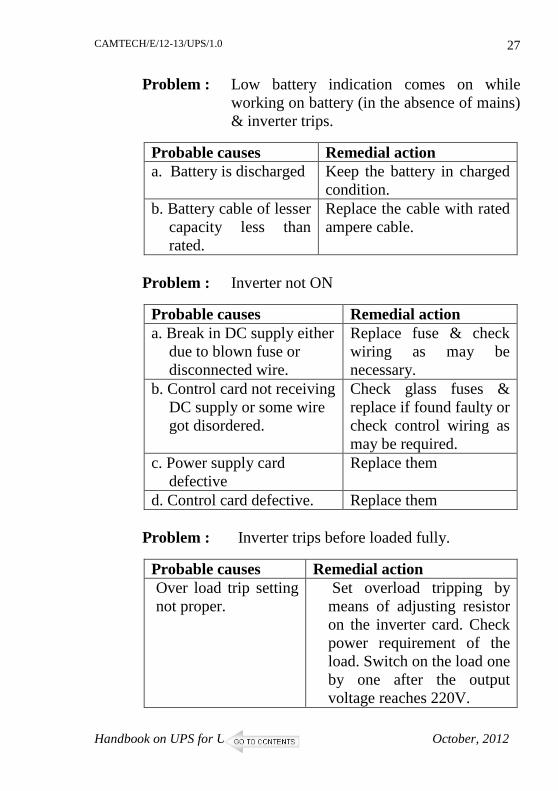
Problem : Low battery indication comes on while working on battery (in the absence of mains) & inverter trips.
Probable causes Remedial action a. Battery is discharged Keep the battery in charged
condition. b. Battery cable of lesser
capacity less than rated.
Replace the cable with rated ampere cable.
Problem : Inverter not ON
Probable causes Remedial action a. Break in DC supply either
due to blown fuse or disconnected wire.
Replace fuse & check wiring as may be necessary.
b. Control card not receiving DC supply or some wire got disordered.
Check glass fuses & replace if found faulty or check control wiring as may be required.
c. Power supply card defective
Replace them
d. Control card defective. Replace them Problem : Inverter trips before loaded fully.
Probable causes Remedial action Over load trip setting not proper.
Set overload tripping by means of adjusting resistor on the inverter card. Check power requirement of the load. Switch on the load one by one after the output voltage reaches 220V.
CAMTECH/E/12-13/UPS/1.0
October, 2012 Handbook on UPS for UTS
28
Problem : Inverter output high
Probable causes Remedial action a. Feedback loop
broken Check feedback on transformer or beak in wiring of transformer or adjust voltage on potentiometer
b. Inverter control card not functioning properly.
Replace control card
c. False indication due to defective O/V sensing circuit.
Check and set right O/V sensing circuit.
Problem : Unit not working on inverter as well as on
mains mode.
Probable causes Remedial action Output fuse is blown. Replace the fuse.
IGBT or Insulated Gate Bipolar Transistor is a device that combines the Metal Oxide Semiconductor Field Effect Transistor (MOSFET) gate driving characteristics with the high current and low saturation voltage of bipolar transistor. It acts as a high frequency, high current switch which is used in AC/DC Inverter, motor control and in switching mode power supplies applications.
The IGBT technology is improving with better switching speed, lower conduction voltage drop, higher current carrying capability and higher reliability. These devices are available with current up to 1 kA, voltage ratings up to 2 kV, switching speeds of 200 ns and on state voltage down to 2.0 V and below.
CAMTECH/E/12-13/UPS/1.0
October, 2012 Handbook on UPS for UTS
30
Q.2 What is Pulse-Width Modulation (PWM)?
Ans. Pulse-Width Modulation (PWM) or pulse-duration modulation (PDM), is a commonly used technique for controlling power to inertial electrical devices, made practical by modern electronic power switches.
The average value of voltage (and current) fed to the load is controlled by turning the switch between supply and load on and off at a fast pace. The longer the switch is on compared to the off periods, the higher the power supplied to the load is.
The main advantage of PWM is that power loss in the switching devices is very low. When a switch is OFF there is practically no current, and when it is ON, there is almost no voltage drop across the switch. Power loss, being the product of voltage and current, is thus in both cases close to zero. PWM also works well with digital controls, which, because of their on/off nature, can easily set the needed duty cycle.
Q.3 What is Digital Signal Processor (DSP)?
Ans. A Digital Signal Processor (DSP) is a specialized microprocessor with an architecture optimized for the fast operational needs of digital signal processing.
Digital signal processing algorithms typically require a large number of mathematical operations to be performed quickly and repeatedly on a set of data. Signals (perhaps from audio or video sensors) are constantly converted from analog to digital, manipulated digitally and then converted back to analog form. because of power supply and space constraints. A specialized digital
CAMTECH/E/12-13/UPS/1.0
Handbook on UPS for UTS October, 2012
31
signal processor, however, will tend to provide a lower-cost solution, with better performance, lower latency, and no requirements for specialized cooling or large batteries.
Q.4 What is MICROPROCESSOR?
Ans. MICROPROCESSOR
A microprocessor incorporates the functions of a computer's central processing unit (CPU) on a single integrated circuit (IC ), or at most a few integrated circuits.
It is a multipurpose, programmable device that accepts digital data as input, processes it according to instructions stored in its memory, and provides results as output. It is an example of sequential digital logic, as it has internal memory. Microprocessors operate on numbers and symbols represented in the binary numeral system.
Q.5 What is MICROCONTROLLER? Ans. MICROCONTROLLER
A microcontroller (sometimes abbreviated µC, uC or MCU ) is a small computer on a single integrated circuit containing a processor core, memory, and programmable input/output peripherals.
CAMTECH/E/12-13/UPS/1.0
October, 2012 Handbook on UPS for UTS
32
Q.6 What is ISOLATION TRANSFORMER? Ans. ISOLATION TRANSFORMER
An isolation transformer is a transformer, often with symmetrical windings, which is used to decouple two circuits. An isolation transformer allows an AC signal or power to be taken from one device and fed into another without electrically connecting the two circuits. Isolation transformers block transmission of DC signals from one circuit to the other, but allow AC signals to pass. They also block interference caused by ground loops. Isolation transformers with electrostatic shields are used for power supplies for sensitive equipment such as computers or laboratory instruments.
Q.7 What is an Uninterrupted Power Supply(UPS)? Ans. An Uninterrupted Power Supply (UPS) is a system intended to solve the mains disturbances and mains failure. The battery attached to the UPS enables the user to work during mains failure. Putting the UPS between the mains and computer system does this. Q.8 How do I size my requirement of UPS? A.8 Check the plate at the back of the equipment near the
mains inlet. It will usually give a figure in watts (w) or Amps (A). If in Amps, multiply the line voltage by the figure given to arrive at a VA (Volt-Amp) rating. Add 25%, which is what UPS, are rated in.
CAMTECH/E/12-13/UPS/1.0
Handbook on UPS for UTS October, 2012
33
Q.9 How does one select the battery? Ans. Battery selection depends upon the back up time required
which in turn depends upon the frequency of power failure, average programmed length and the presence of the other backup source like a diesel generator set. One thing to remember is that the ampere hour ratings quoted by battery manufacturers are on a ten hour discharge basis and normally the back up time required will be much shorter; sufficient either to finish an almost complete job or to take a systematic shut down or to start the generator set. However, when the battery is discharged in a shorter time a de-rating factor has to be used which incidentally does not vary below 20 to 30 minutes. So approx half an hour is a sensible back up time to select.
Q.10 What is the difference between the UPS categories: OFF-LINE, LINE INTERACTIVE, ON- LINE? Ans. (A) OFF-LINE UPS
The OFF-LINE UPS supplies (or routes) the incoming mains supply directly to the output usually through a relay contact. Some high frequency noise filtering and surge suppression may be included in this path. The UPS switches ON its inverter as soon as mains supply failure is detected or below the normal input voltage and simultaneously switches the output relay to the inverter side to supply battery sourced power to the load. This transition involves a delay on account of the time to reliably detect mains failure and switch over a relay, and the output is broken for this period (usually for
CAMTECH/E/12-13/UPS/1.0
October, 2012 Handbook on UPS for UTS
34
2 to 12 msec). OFF-LINE UPS are usually the least expensive as compared to the other two.
(B) LINE INTERACTIVE UPS
The true LINE INTERACTIVE design is in fact a combination of OFF-LINE & ON-LINE, in which the inverter plays a dual role of charging the battery when mains supply is present as well as regulating the output voltage and working as a normal inverter in absence of mains supply, so to the user it appears like an ON-LINE System. Line Interactive UPS offers enhanced power protection over the basic Off-line designs by providing additional line conditioning.
Surge
Suppressor
Filter
Battery
Charger
Battery DC
AC
Transfer Switch
Inverter Output
Input
Battery
AC
DC
Filter
AVR (Automatic voltage regulator) Transfer switch Surge Suppressor
Inverter
Charging
Discharging
Output
Input
CAMTECH/E/12-13/UPS/1.0
Handbook on UPS for UTS October, 2012
35
(C) ON-LINE UPS
An ON-LINE UPS is the one in which the inverter always supplies power to the protected load and hence the same quality of power is ensured all the time. When mains supply is present, the inverter derives its power from the mains supplied rectifier and the backup batteries are also kept in charged state. When the mains fail, the source of DC power for the inverter section shifts to the batteries without any break. It also bears all the vagaries and noise borne out of the mains supply and insulates the secure bus supply from it. An ON-LINE UPS is especially useful for sensitive and critical equipments/devices.
Q.11 Is UPS system really necessary for computers?
Ans. For a reliable and safe computer system, precautions are taken to ensure that ‘garbage’ doesn’t enter into the system through software. But there is one more source of garbage, of a more serious nature, which is not normally taken care of. That is in the form of garbage power input to the computer, it is more serious because besides malfunctioning and operational problems, it can also cause permanent damage to the computer system.
Rectifier
AC To DC DC to AC
Batteries
Inverter Rectifier
Output
CAMTECH/E/12-13/UPS/1.0
October, 2012 Handbook on UPS for UTS
36
Q.12 What is exactly meant by ‘garbage’ power?
Ans. It is commonly known that there are fluctuations in utility (mains) supply. For example; some times the utility voltage is as low as 170 to 160 volts and high as 280 to 300 volts. Besides this, there are many more hidden culprits associated with utility lines like sags and surges, oscillatory transients, EMI and RFI, brown outs, harmonics or total loss of power etc.
Q.13 How does all this applies to computer system?
Ans. The computer system, to which this power is feeding, is extremely sensitive to the quality of power and is termed as critical equipment. Imagine a sudden failure of computers during busy hours when a critical operation is in progress. All this can occur due to garbage power fed to such equipment. The above problem may be of malfunctioning or operational nature. These can be time consuming and expensive. Besides, like all electronic circuits, the computer circuits can also undergo irreparable damage due to high voltage surges and spikes, which can reach several kilovolts.
Q.14 Is computer’s load falls under special category of load?
Ans. Most certainly. The current drawn by computers is discontinuous and rich in third harmonics of fundamental 50Hz supply. The third harmonic currents in the three phases peak simultaneously, overloading the neutral return wire and cause failures. The harmonic currents may have to be filtered out, particularly in largely SMPS fed installations (computer installations). Neutral wire should be at least the same size as for the phase.
CAMTECH/E/12-13/UPS/1.0
Handbook on UPS for UTS October, 2012
37
Q.15 How long does batteries last in a UPS? Ans. Battery life depends upon number of factors, viz.
- Temperature
- Number of discharge experienced
- Number of deep discharges experienced
- Specification of the batteries
Battery life is halved for every 10 degrees Centigrade temperature increase above its specified operating temperature (usually 25 degree Centigrade).
At installation time, the battery is at 100 percent of rated capacity. Each discharge and subsequent recharge reduces the relative capacity of the battery by a small percentage. The length of the discharge cycle will determine the reduction in battery capacity. So-called deep discharges on a repeated basis will reduce the life of the battery.
The loaf of “bread” analogy is most often used to illustrate the relationship between cycling and battery life. A loaf of bread can either be cut into many thin slices or a few thicker slices. Similarly, a UPS battery can provide power over a large number of short cycles, or fewer cycles of long duration.
The IEEE defines “end of useful life” for a UPS battery as being the point when it can no longer supply 80 percent of its rated capacity in ampere-hours. The relationship between amp-hours and load protection time is not linear, a 20% reduction in capacity results in a much greater reduction in protection time.
CAMTECH/E/12-13/UPS/1.0
October, 2012 Handbook on UPS for UTS
38
Q.16 One of the batteries has failed in the UPS battery bank, is it all right to replace just one battery?
Ans. If the batteries are less than twelve months old then the failure could be due to a manufacturing or material fault. In this instance the failed battery can be replaced after confirmation by testing the whole battery bank.
In general once the batteries are over twelve months old, the failure is more likely to be due to age, environment or usage and the whole bank should be replaced. Failure to replace the whole bank could result in the new battery not being charged properly and connected load being at risk if any or all of the older batteries fail.
Q.17 How do I maintain and service the batteries and the UPS?
Ans. Gradual decrease in battery life can be periodically monitored and evaluated by:
- Voltage Checks
- Load testing
- Checking for proper battery connections
- Checking for battery water (in case of lead acid batteries)
Without regular maintenance and service checks, UPS battery may experience:
- Heat-generating resistance at the terminals
- Improper loading
- Reduced protection
- Premature failure or reduced backup
CAMTECH/E/12-13/UPS/1.0
Handbook on UPS for UTS October, 2012
39
Q. 18 How long can I leave the UPS switched off without damaging the batteries? Ans. As long as the batteries are fully charged when the unit is
switched off they will not require charging for three months. Cold start feature of Power Pack Line Interactive UPS isolates the batteries from the UPS circuit and thus the UPS can be switched off for longer period (six months approx.) without damaging the batteries.
Q.19 What is the right step to install UPS? Ans. Recharge the UPS for at least eight hrs before the first
operation. Every UPS passes the quality examination before it is shipped out of factory. These QC parameters consume the battery power of UPS. It is strongly recommended to recharge the UPS before using it at every first time to make sure that battery is in fully charged condition.
Q.20 What is Load Crest Factor? Ans. A pure sine waveform has a peak value, which is 1.414
times the RMS value indicated on a voltmeter. A resistance or any linear load connected to such a voltage source draws current having similar waveforms and hence has a crest factor of 1.4. As against this, the non-linear loads as computers etc. may demand currents whose peak value to RMS ratios are 2 to 5 or more. This ratio of peak to RMS is termed as the crest factor, and is indicative of the degree of non-linear load handling capability of the UPS.
CAMTECH/E/12-13/UPS/1.0
October, 2012 Handbook on UPS for UTS
40
Q21. What is SNMP ? Ans. Simple Network Management Protocol (SNMP) is an
"Internet-standard protocol for managing devices on IP networks." Devices that typically support SNMP include routers, switches, servers, workstations, printers, modem racks, and more. It is used mostly in network management systems to monitor network-attached devices for conditions that warrant administrative attention.
SNMP is a component of the Internet Protocol
Suite as defined by the Internet Engineering Task Force (IETF). It consists of a set of standards for network management, including an application layer protocol, a database schema, and a set of data objects.
SNMP exposes management data in the form of
variables on the managed systems, which describe the system configuration. These variables can then be queried (and sometimes set) by managing applications.
Q.22 What is electromagnetic interference? Ans. Electromagnetic interference, EMI, is any undesirable
electromagnetic emission or any electrical or electronic disturbance, man-made or natural, which causes an undesirable response, malfunctioning or degradation in the performance of electrical equipment.
Q.23 What is radio frequency interference? Ans. Radio frequency interference, RFI, is any undesirable
electrical energy with content within the frequency range dedicated to radio frequency transmission. Conducted RFI
CAMTECH/E/12-13/UPS/1.0
Handbook on UPS for UTS October, 2012
41
is most often found in the low frequency range of several kHz to 30MHz. Radiated RFI is most often found in the frequency range from 30MHz to 10GHz.
Q24. How does interference propagate? Ans. EMI or RFI propagate through conduction over signal and
power lines and through radiation in free space. Q.25 What are some common sources of conducted
interference? Ans. Typical sources of conducted interference include
switching power supplies, ac motors, and microprocessors. In short, just about any electrical and electronic device has the potential to generate conducted and radiated interference.
Q.26 What are some common sources of radiated
interference? Ans. The most common offender in the radiation of EMI is the
electrical power cord of the electronic device itself. Since the powercord can act as an antenna, conducted EMI can also become radiated interference.
Q.27 What is an EMI filter? Ans. An EMI filter is a passive electronic device used to
suppress conducted interference present on any power or signal line. It may be used to suppress the interference generated by the device itself as well as to suppress the interference generated by other equipment to improve the immunity of a device to the EMI signals present within its
CAMTECH/E/12-13/UPS/1.0
October, 2012 Handbook on UPS for UTS
42
electromagnetic environment. Most EMI filters include components to suppress both common and differential mode interference. Filters can also be designed with added devices to provide transient voltage and surge protection as well as battery backup.
Q.28 How does an EMI filter work? Ans. An EMI filter has a high reactive component to its
impedance. That means the filter looks like a much higher resistance to higher frequency signals. This high impedances attenuates or reduced the strength of these signals so they will have less of an effect on other devices.
Q.29 Explain Battery size selection with the help of an
example for 3 kVA UPS.
A.29 Battery Size Selection for 3 kVA 215V, single phase UPS
We know
UPS capacity = 3 kVA, 215V, 1 phase
Assumptions:
i. DC voltage = 216 V (Nearest even no. as battery shall be in multiple of cell voltage 2.0 volts)
ii. Voltage of each Battery = 12 V
iii. End Cell voltage of 12 V battery = 10.5 V
iv. Load power factor = 1.0
v. Inverter efficiency = 93%
vi. % capacity utilization for 1 hr. = 62% *
vii. Back up time required = 1 hr
CAMTECH/E/12-13/UPS/1.0
Handbook on UPS for UTS October, 2012
43
* (As per information received from M/s Numeic/ Luclnow): % capacity utilization respect to back up time
Calculations: (A) DC voltage Nos. of batteries required = --------------------------------
Voltage of each Battery = 216/12 = 18 nos.
(B) Battery DC current = UPS Capacity (in VA) x power factor = ------------------------------------------------------------------ Inv. Efficiency x battery end voltage x no. of batteries 3000 x 1 = --------------------- 0.93 x 10.5 x 18 = 17.07 = 17.0 Amp. (C) Battery DC current x Back up time required Battery AH = ----------------------------------------------------------- % capacity utilization for back up time
17.0 x 1 = ----------- = 27.42 = 28 AH 0.62
Hence 18 nos. of 12V, 28 AH batteries shall be required for 3 kVA UPS.
CAMTECH/E/12-13/UPS/1.0
October, 2012 Handbook on UPS for UTS
44
(D) Total VAH
= nos. of batteries x battery voltage x battery AH
1. RDSO specification no. RDSO/PE/SPEC/PS/0023-2001 (REV ‘0’) Amdt. No.3, Sept. 2011 for Technical Specification for Fault Tolerant uninterrupted power supply (UPS) system for PRS, EDP centres and other similar requirements of ON line UPS system.
2. Information collected from NPS Power Industries,
Lucknow for ON line UPS. 3. Instructions cum installation manuals for ON line UPS from
Numeric UPS. 4. Literature collected from various railways. 5. Suggestions received during the seminar held on
To upgrade maintenance technologies and methodologies and achieve improvement in productivity and performance of all Railway assets and manpower which inter-alia would cover reliability, availability, utilisation and


![Hkwdai rRijrk gsrq ekxZnf'kZdk - mpsdma.mp.gov.in filedj ldrs gSaA vko’;d dkjZokbZ djus ds fy, izR;sd ukxfjd ds fy, ;g cqfu;knh Kku vfuok;Z gS fd Hkwdai D;k gksrk gS] lajpukvksa](https://static.documents.pub/doc/80x56/5cf8b74888c993103e8c8531/hkwdai-rrijrk-gsrq-ekxznfkzdk-ldrs-gsaa-vkod-dkjzokbz-djus-ds-fy-izrsd.jpg)


![fdlkuksa ds fy, foÙkh; lk{kjrk - psbindia.com Hindi Version.pdf · fdlkuksa ds fy, foÙkh; lk{kjrk Hkys gh vkidh Qly vPNh gqbZ gS rks Hkh vkidk vk/kk dke gh iwjk gqvk gS] D;ksafd](https://static.documents.pub/doc/80x56/5ba9ecb909d3f2cf6d8b57e5/fdlkuksa-ds-fy-foukh-lkkjrk-hindi-versionpdf-fdlkuksa-ds-fy-foukh.jpg)


![jkT; fuokZpu vk;ksx] >kj[k - secjharkhand.nic.insecjharkhand.nic.in/pdf/circ_municipal/Vol-I/Municipal election... · 3 3- fuokZpu lEiUu djkus gsrq dkfeZdksa ds pquko ds fy, jS.MekbZts’ku](https://static.documents.pub/doc/80x56/5aa4bbeb7f8b9afa758c473d/jkt-fuokzpu-vkksx-kjk-election3-3-fuokzpu-leiuu-djkus-gsrq-dkfezdksa-ds.jpg)
![R.N.TAGORE CHILD cPpksa ij ikB~;p;kZ ds cks> ds ekeys esa yxrk gS] ge fdlh xrZ esa fxjs iM+s gSaA geus le> ds cnys FkksM+s oDr ds fy, dke vkus okyh tkudkjh.](https://static.documents.pub/doc/80x56/5665b4951a28abb57c926617/rntagore-child-cppksa-ij-ikbpkz-ds-cks-ds-ekeys-esa-yxrk-gs-ge-fdlh.jpg)


![Haryana Government Gazette · 2021. 1. 8. · izkd`frd fodkl dh izo`fÙk dks /;ku esa j[krs gq, vkSj ’kgj ds Hkfo"; ds fodkl ds fy,] Hkwfe mi;ksx forj.k vkSj ifjlapj.k iSVuZ ds](https://static.documents.pub/doc/80x56/60ca5e0a5a2d4e68f30e29bd/haryana-government-gazette-2021-1-8-izkdfrd-fodkl-dh-izofk-dks-ku-esa.jpg)