WW OPS WW OPS-9 Equipment Monitoring System (EMS) Equipment Monitoring System (EMS) Project Overview Project Overview “Implementing an Operations Information Infrastructure” Ken Kovacs, CMC Quality Business Systems Manager Fujirebio Diagnostics, Inc. October 13, 2013
Transcript
WW OPSWW OPS--99Equipment Monitoring System (EMS)Equipment Monitoring System (EMS)
Project OverviewProject Overview“Implementing an Operations Information Infrastructure”
Ken Kovacs, CMCQuality Business Systems Manager
Fujirebio Diagnostics, Inc.
October 13, 2013
AgendaAgenda
• Fujirebio Diagnostics, Inc. – Who we are…• Project Objectives & System Overview• User Navigation & System Functionality• Benefits & Future Expansion Capabilities• Project Success Principals
• Fujirebio Diagnostics, Inc. – Who we are…• Project Objectives & System Overview• User Navigation & System Functionality• Benefits & Future Expansion Capabilities• Project Success Principals
Fujirebio Diagnostics, Inc.Fujirebio Diagnostics, Inc.
• For over 20 years, Fujirebio Diagnostics, Inc. is the trusted source ofinnovative solutions in clinical diagnostics.
• Fujirebio Diagnostics’ products form the base of a product line thathas been long recognized as the worldwide standard of excellencein cancer biomarkers.
• Our core technology is based on our proprietary monoclonalantibodies originally developed to detect a variety of tumor markers.
• To learn more about Fujirebio Diagnostics’ products available in theUnited States please visit our website at http://www.fdi.com
• We are located in Malvern, PA– Proven manufacturing process, GMP Compliant, ISO 9001 and ISO 13485
certified quality system– Successful FDA inspection record
The world’s most extensive array of biomarkersThe world’s most extensive array of biomarkersfor disease states with a focus on oncology.for disease states with a focus on oncology.The world’s most extensive array of biomarkersThe world’s most extensive array of biomarkersfor disease states with a focus on oncology.for disease states with a focus on oncology.
Gold Standard Bio MarkersGold Standard Bio Markers• CA 125 II™ - Ovarian Cancer• CA 19-9™ - Pancreatic Cancer• CA 15-3® - Breast Cancer• CA 72-4® - Gastrointestinal
“Everyday 1000’s of people, all over the world, live a better life because of the thingswe do here. There is no better way to make a living, than by helping others.”
Grady Barnes Ph. D., Chief Scientific Officer, Fujirebio Diagnostics, Inc.
“Everyday 1000’s of people, all over the world, live a better life because of the thingswe do here. There is no better way to make a living, than by helping others.”
Grady Barnes Ph. D., Chief Scientific Officer, Fujirebio Diagnostics, Inc.
Project Objective / System OverviewProject Objective / System Overview
“To replace an existing paper-based GMP record system andmanual process for logging equipment temperature readingsand related process data and information” Allow personnel to monitor equipmentmonitor equipment from their Workstations Maintain all temperature readings in electronic recordselectronic records Generate electronic GMP reports for “review by exception”review by exception” Provide authorized personnel electronic signatureelectronic signature capabilities to
approve reports NotifyNotify authorized personnelauthorized personnel in event of adverse temp trendstrends ReduceReduce current paper-based logging effort (now over 1100 hrs.) Implement an Operations Information InfrastructureOperations Information Infrastructure to simplifysimplify
the installation of future “electronic initiative” projects
System ConsiderationsSystem Considerations
• A dedicated Equipment Monitoring System wasproposed and quotes obtained.– A focused application– Limited flexibility
• A PLC / HMI / MOM Server-based solution wasthen discussed, specified, and quotes obtained.– Included a new operations-level infrastructure
• To provide a basis for implementing new applications
– EMS solution specified as first application– About 50% higher cost than dedicated EMS, but overall
less expensive and more efficient than implementing aseries of future standalone systems.
– Decision made: This was our Solution of Choice
Software SolutionSoftware Solution
Applied-Solution Chosen:Flexible system configured as an “Equipment Monitoring” application
• Wonderware System Platform
• Wonderware InTouch Interface
• Wonderware Historian
• Wonderware Workflow Software
• Programmable Logic Controller (PLC) with Point I/O in 18 controlpanels distributed within the Malvern, PA facility
• Configurable for addressing other operations, manufacturing,and facilities applications through a common unified platform
• Future application expansion capabilities through a new“Operations Information Infrastructure”
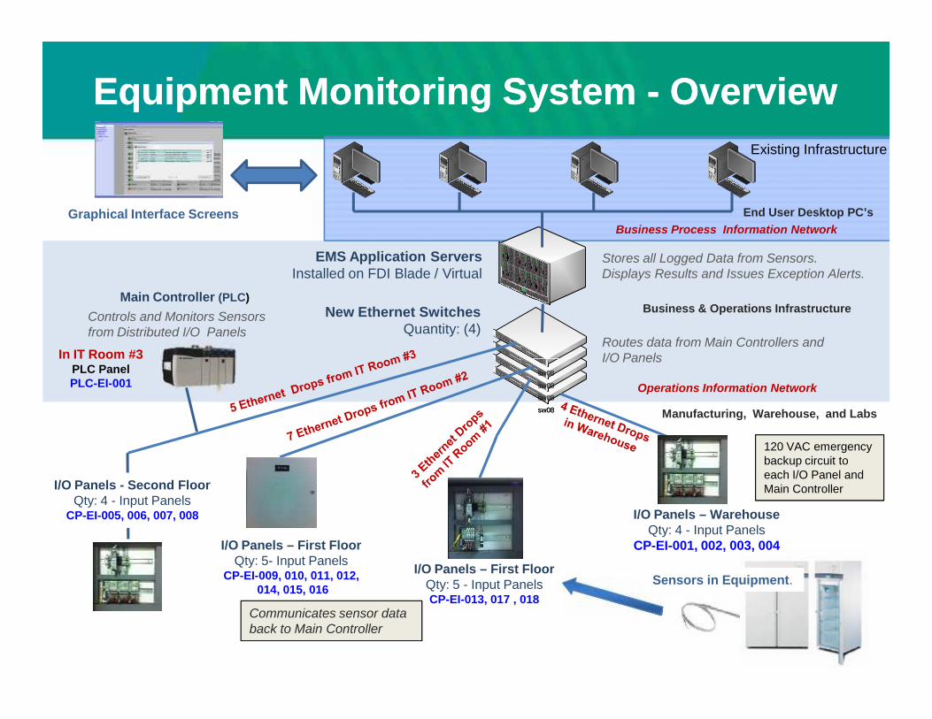
Equipment Monitoring SystemEquipment Monitoring System -- OverviewOverview
EMS Application ServersInstalled on FDI Blade / Virtual
New Ethernet SwitchesQuantity: (4)
Graphical Interface Screens
Main Controller (PLC)
Stores all Logged Data from Sensors.Displays Results and Issues Exception Alerts.
Routes data from Main Controllers andI/O Panels
Controls and Monitors Sensorsfrom Distributed I/O Panels
End User Desktop PC’s
In IT Room #3PLC PanelPLC-EI-001
Business & Operations Infrastructure
Business Process Information Network
Existing Infrastructure
Operations Information Network
sw08sw08
sw08
sw08
sw08
Sensors in Equipment.
Manufacturing, Warehouse, and Labs
Routes data from Main Controllers andI/O Panels
Communicates sensor databack to Main ControllerCommunicates sensor databack to Main Controller
• The EMS consists of 4 servers,1 engineering workstation, adata collection PLC, and 18PLC Input / Output Panels.
• A dedicated Ethernet networkwas installed in Operations byFDI to enable communicationsbetween the Data Collection /Concentrator PLC, I/O panels,and the Wonderware ArchestrAapplication server.
• FDI system users access theEMS via secured logon throughtheir current workstations usingweb browsers.
Business Process Information Network
• The EMS consists of 4 servers,1 engineering workstation, adata collection PLC, and 18PLC Input / Output Panels.
• A dedicated Ethernet networkwas installed in Operations byFDI to enable communicationsbetween the Data Collection /Concentrator PLC, I/O panels,and the Wonderware ArchestrAapplication server.
• FDI system users access theEMS via secured logon throughtheir current workstations usingweb browsers.
EMS Summary Report for ApprovalEMS Summary Report for Approval
PaperPaper--based GMP Packsbased GMP Packs
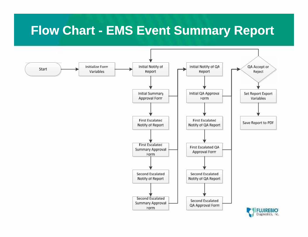
WorkflowWorkflow -- EMS System EventEMS System Event
• Handles response to system events, such as detecting acommunication failure between the Application ObjectServer (AOS) and the PLC.
• Notification of the event is emailed to designated user(“initial actor”).
• An acknowledgement (email reply) is required.• Two levels of escalation are configured (1st & 2nd actors)• Once one of the three actors has responded to the
notice, they will receive an email notice that theelectronic signature form is in their Workflow inbox.
• Once the form is completed with comments and signed,the workflow is complete.
Flow ChartFlow Chart -- EMS System EventEMS System Event
WorkflowWorkflow -- EMS System EventEMS System Event
What Occurs During the MonthWhat Occurs During the Month
• Temperature data is automatically logged– Exceptions are identified by EMS and owners notified– Equipment owners comment on exceptions & sign-off– Exceptions and sign-offs captured for Summary Report
• Summary Reports are generated monthly– Reports only contain exceptions– Routed to departments for review and approval– Then routed to QA for review and approval
• EMS automatically stores approved SRs as e-files– SRs available for future access as needed– Historical data available to generate equipment logs
EMSEMS –– Future Expansion through…Future Expansion through…Operations Information InfrastructureOperations Information Infrastructure
Computer Network and End User Desktop PC’s
Example: Electronic Batch Record
Future Expansion Capabilities• Batch Data Management EBR• Process Equipment – Monitor & Control• Weigh Scale Automation Application• Track & Trace / Genealogy• Statistical Process Control / Analytics• Clean Room Monitoring• Purified Water Systems Monitoring• Manufacturing Equipment Integration• Manufacturing Operations Management• Bioreactor monitoring• Operations Dashboards: OEE, Quality, WIP• Bar Code Applications
Future Expansion Capabilities
Operations InformationInfrastructure / Network
Controller &Input/Output Panels
Infrastructure providedthrough this Project
Infrastructure providedthrough this Project
(Future) Manufacturing &Operations Applications
Equipment MonitoringApplication
Weigh Scales(Future)
Purified Water(Future)
EBR(Future)
“Information-on-Demand”
Future Expansion Capabilities• Batch Data Management EBR• Process Equipment – Monitor & Control• Weigh Scale Automation Application• Track & Trace / Genealogy• Statistical Process Control / Analytics• Clean Room Monitoring• Purified Water Systems Monitoring• Manufacturing Equipment Integration• Manufacturing Operations Management• Bioreactor monitoring• Operations Dashboards: OEE, Quality, WIP• Bar Code Applications
Added System BenefitsAdded System Benefits
• Ability to observe historical data and save graphs for eachpiece of equipment.
• Obtain information for better understanding of processes• Ability to analyze equipment operations:
– Better controller tuning for more efficient operations– Able to better see impact of equipment cycling during 7 day / 24
hour operations
•• As an Operations Information Infrastructure, this systemAs an Operations Information Infrastructure, this system is alreadyis alreadybeingbeing usedused toto provide data input for continuousprovide data input for continuous improvement.improvement.
•• Future expectations include process analysis and improvementsFuture expectations include process analysis and improvementsthrough a Process Analytical Technology (PAT) Framework.through a Process Analytical Technology (PAT) Framework.
Example Report for Equipment AnalysisExample Report for Equipment Analysis
Project Completion1. Qualification / Validation / Calibration2. Training3. Run in parallel w/ paper records4. Acceptance & Final Turnover
Project Completion1. Qualification / Validation / Calibration2. Training3. Run in parallel w/ paper records4. Acceptance & Final Turnover
User Community69 different users trained and givensecured access the system(out of a total of 185 site employees)
User Community69 different users trained and givensecured access the system(out of a total of 185 site employees)
Every Department at FDI…and over 80 employees were involved with the successful implementation of this project.Every Department at FDI…and over 80 employees were involved with the successful implementation of this project.
Project Success Principals:Project Success Principals:FDI System Development Life Cycle (SDLC) SOPFDI System Development Life Cycle (SDLC) SOP
Supported by a pragmatic Project Management methodologySupported by a pragmatic Project Management methodology
• Ongoing user and team involvement• Frequent communications w/ user groups• Internal group discussion meetings prior to routing
complex documents for approvals (such as FRS and DDS)• Continuous cost management
– DIY & periodic reconciliation w/ accounting
• Periodic meetings with System Integrator & other serviceproviders and suppliers, formalized through:– Meeting Agendas– Meeting Minutes, Notes, and Agreements
• Training: User, Administration, and Support Personnel• Acknowledge and thank contributors and team participants
• “…a justified and documented risk assessment and a determination of thepotential of the system to affect product quality and safety, and record integrity”.
FDA Guidance for Industry: Part 11, Electronic Records; Electronic Signatures – Scope and Application
• “…a justified and documented risk assessment and a determination of thepotential of the system to affect product quality and safety, and record integrity”.
FDA Guidance for Industry: Part 11, Electronic Records; Electronic Signatures – Scope and Application
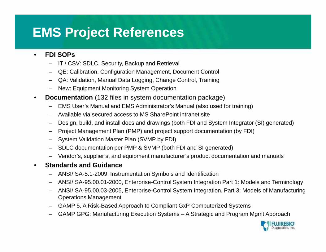
– IT / CSV: SDLC, Security, Backup and Retrieval– QE: Calibration, Configuration Management, Document Control– QA: Validation, Manual Data Logging, Change Control, Training– New: Equipment Monitoring System Operation
• Documentation (132 files in system documentation package)– EMS User’s Manual and EMS Administrator’s Manual (also used for training)– Available via secured access to MS SharePoint intranet site– Design, build, and install docs and drawings (both FDI and System Integrator (SI) generated)– Project Management Plan (PMP) and project support documentation (by FDI)– System Validation Master Plan (SVMP by FDI)– SDLC documentation per PMP & SVMP (both FDI and SI generated)– Vendor’s, supplier’s, and equipment manufacturer’s product documentation and manuals
• Standards and Guidance– ANSI/ISA-5.1-2009, Instrumentation Symbols and Identification– ANSI/ISA-95.00.01-2000, Enterprise-Control System Integration Part 1: Models and Terminology– ANSI/ISA-95.00.03-2005, Enterprise-Control System Integration, Part 3: Models of Manufacturing
Operations Management– GAMP 5, A Risk-Based Approach to Compliant GxP Computerized Systems– GAMP GPG: Manufacturing Execution Systems – A Strategic and Program Mgmt Approach
• FDI SOPs– IT / CSV: SDLC, Security, Backup and Retrieval– QE: Calibration, Configuration Management, Document Control– QA: Validation, Manual Data Logging, Change Control, Training– New: Equipment Monitoring System Operation
• Documentation (132 files in system documentation package)– EMS User’s Manual and EMS Administrator’s Manual (also used for training)– Available via secured access to MS SharePoint intranet site– Design, build, and install docs and drawings (both FDI and System Integrator (SI) generated)– Project Management Plan (PMP) and project support documentation (by FDI)– System Validation Master Plan (SVMP by FDI)– SDLC documentation per PMP & SVMP (both FDI and SI generated)– Vendor’s, supplier’s, and equipment manufacturer’s product documentation and manuals
• Standards and Guidance– ANSI/ISA-5.1-2009, Instrumentation Symbols and Identification– ANSI/ISA-95.00.01-2000, Enterprise-Control System Integration Part 1: Models and Terminology– ANSI/ISA-95.00.03-2005, Enterprise-Control System Integration, Part 3: Models of Manufacturing
Operations Management– GAMP 5, A Risk-Based Approach to Compliant GxP Computerized Systems– GAMP GPG: Manufacturing Execution Systems – A Strategic and Program Mgmt Approach
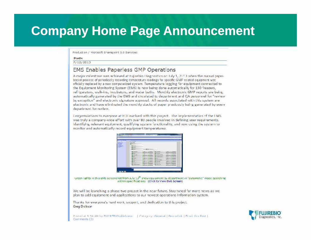
Company Home Page AnnouncementCompany Home Page Announcement
Questions / DiscussionQuestions / Discussion
Equipment Monitoring System (EMS)Project OverviewProject Overview
“Implementing an Operations Information Infrastructure”
Fujirebio Diagnostics, Inc. contact:Ken Kovacs, Quality Business Systems ManagerEmail: [email protected]