51
Health Canada Santé Canada X-ray Equipment in Medical Diagnosis Part A: Recommended Safety Procedures for Installation and Use Safety Code 20A

HealthCanada
SantéCanada
X-ray Equipment in Medical DiagnosisPart A:Recommended Safety Procedures forInstallation and Use
Safety Code 20A

X-ray Equipment in Medical DiagnosisPart A:Recommended Safety Procedures forInstallation and Use
Safety Code 20A
Healthy Environments and Consumer Safety Branch
Published by authority of theMinister of Health
Également disponible en français sous le titre
80-EHD-65
Les appareils radiographiques endiagnostic médical partie A

Our mission is to help the people of Canadamaintain and improve their health.
Health Canada
Reprinted 1983Reprinted 1987Reprinted 1990Reprinted 1992Reprinted 1996Revised 1999
Website address: www.hc-sc.gc.ca/rpb
© Minister of Public Works and Government Services Canada 2000Cat. H46-2/00-65E
ISBN: 0-662-29034-8
Table of ContentsPage
Explanatory notes 6
1. Introduction 9
2. Scope and principal aims of the Code 112.1 Principal aims 112.2 Scope 11
3. Responsibility and personnel 123.1 Responsibility 123.2 X-ray equipment operators 143.3 Students or operators-in-training 14
4. Building and installation requirements 154.1 Design criteria 154.2 General recommendations 16
5. Radiation protection surveys 185.1 General procedures 185.2 Survey report 19
6. Equipment specifications 216.1 New x-ray equipment 216.2 Existing x-ray equipment 216.3 Protective clothing 296.4 Film cassettes 29
7. Darkroom and film processing 317.1 Darkroom 317.2 Film processing 327.3 Film storage 32
8. Procedures to reduce dose to x-ray personnel 338.1 General recommendations 338.2 Recommendations for operation of
radiographic units 348.3 Recommendations for operation of
fluoroscopic units 35
32

8.4 Recommendations for operation ofmobile units 35
8.5 Recommendations for operation ofphotofluorographic units 36
8.6 Recommendations for special radiologicalprocedures 36
9. Procedures for minimizing dose to patients 389.1 Guidelines for the prescription of diagnostic x-ray
examinations 389.2 Guidelines for radiography of pregnant women 399.3 Guidelines for radiographic examination
of the breast (mammography) 419.4 Radiological chest screening 419.5 Guidelines for carrying out x-ray examinations 429.5.1 General Recommendations 429.5.2 Recommendations for radiographic procedures 439.5.3 Recommendations for fluoroscopic procedures 459.5.4 Recommendations for photofluorographic
procedures 469.5.5 Recommendations for mammography 469.5.6 Recommendations for special procedures 46
10. Guidelines for reduction of gonad dose 4810.1 Recommendations for reducing gonad
dose to the patient 4810.2 Recommendations for reducing gonad dose
to operators 49
Appendices
I: Maximum permissible dose of ionizingradiation to operators and other occupationallyexposed personnel 50
II: Shielding guides for diagnostic x-rayinstallations 52
III: A. Radiation emitting devices regulationsfor photofluorographic x-ray equipment 65
B. Radiation emitting devices regulations fordiagnostic x-ray equipment 72
IV: Shielding guides for storage ofradiographic film 92
V: Agencies responsible for radiation safetyof medical x-ray installations 94
VI: Radiation measurement units— International (SI) System 97
Bibliography 98
4 5
Explanatory notesThis document is one of a series of Safety Codes prepared by the
Radiation Protection Bureau to set out requirements for the safe useof radiation emitting devices. Included in this Code are sections forthe specific guidance of the radiologist, the physician, the operatorand the medical or health physicist concerned with safety procedures,equipment performance and protection surveys.
The safety procedures, equipment and installation guidelinesdetailed in this Code are primarily for the instruction and guidance ofpersons employed in Federal Public Service Departments andAgencies, as well as those coming under the jurisdiction of theCanada Labour Code. This Safety Code is also intended to assist otherusers of equipment that produces x-rays for general patient diagnosis.However, it should be noted that facilities under provincial juris-diction may be subject to requirements specified under provincialstatutes. The authorities listed in Appendix V should be contacted fordetails of the regulatory requirements of individual Provinces.
This Code supersedes Safety Code RPB-SC-4, entitled “X-Raysin Medical, Dental and Paramedical Diagnostic Radiology —Recommended Installation and Safety Procedures”, and it is intendedto complement x-ray equipment design, construction and perform-ance standards promulgated under the Radiation Emitting DevicesAct.
The words “must” and “should” in this Code have been chosenwith purpose. The word “must” indicates a recommendation that isessential to meet the currently accepted standards of protection, while“should” indicates an advisory recommendation that is highlydesirable and that is to be implemented where applicable.
In a field in which technology is advancing rapidly and whereunexpected and unique problems continually occur the Code cannotcover all possible situations. Blind adherence to rules cannot substi-tute for the exercise of sound judgment, so the recommendations mayneed to be modified in unusual circumstances, but only upon theadvice of experts with recognized competence in radiation protec-tion. This Code will be reviewed and revised periodically and aparticular requirement may be reconsidered at any time if it becomesnecessary to cover an unforeseen situation. Interpretation or elabora-tion on any point can be obtained by contacting the Radiation Pro-tection Bureau, Health Canada, Ottawa, Ontario, K1A 1C1.
This Code reflects the results of the work of many individuals,and was compiled and drafted by Dr. W.M. Zuk in cooperation withMr. A. Tod, and Mr. M.H. Repacholi.
Acknowledgements:The various draft versions of this Safety Code were reviewed and
commented on by a number of regulatory authorities and professionaland manufacturers’ associations. The contributions of the followingorganizations and associations to the Code are gratefully acknow-ledged:
Federal/Provincial Subcommittee on Radiation SurveillanceBureau of Radiological Health, U.S. Department of Health andHuman ServicesBureau of Medical Devices, Health CanadaMedical Services Branch, Health CanadaCanadian Association of PhysicistsCanadian Association of RadiologistsCanadian Association of Medical Radiation TechnologistsCanadian Association of Manufacturers of Medical DevicesAcknowledgement is gratefully made to Mr. J. Gordon for
preparation of the graphs in Appendix II. Appreciation is alsoexpressed to Mr. P. Dvorak, Mr. J. Cairnie and Dr. P.J. Waight for theiradvice during the preparation of the Code.
6 7

1. Introduction
Diagnostic x-rays are an essential part of present day medicalpractice. In North America, over 60% of the population with accessto modern medical care undergo radiological procedures each year.Over half of all important decisions for the welfare of patients arebased on radiological procedures. The diagnostic x-ray is thus one ofthe most valuable tools used in modern health care.
Although individual doses are usually small, in total exposure,diagnostic x-rays account for the major portion of man-made radia-tion exposure to the general population. However, with well-designed, installed and maintained x-ray equipment, and through useof proper procedures by trained operators, unnecessary exposure topatients can be reduced significantly, with no decrease in the value ofmedical information derived. To the extent that patient exposure isreduced, there is, in general, a decrease in the exposure of machineoperators and other health care personnel.
The need for radiation protection exists because exposure toionizing radiation can result in deleterious effects that manifest them-selves not only in the exposed individual but in his descendants aswell. These effects are called somatic and genetic effects, respectively.Somatic effects are characterized by observable changes occurring inthe body organs of the individual exposed. These changes may appearwithin a time frame of a few hours to many years, depending on theamount and duration of exposure of the individual. Genetic effectsare an equal cause for concern at the lower doses used in diagnosticradiology. Although the radiation doses may be small and appear tocause no observable damage, the probability of chromosomal damagein the germ cells, with the consequence of mutations giving rise togenetic defects, can make such doses significant when considered fora very large population.
There are four main aspects of the problem to be considered.Firstly, radiological procedures should be based on a demonstratedmedical need. Secondly, when radiological procedures are required,it is essential that patients be protected from excessive radiationduring the exposure. Thirdly, it is necessary that personnel inradiology departments be protected from excessive exposure to
9

radiation in the course of their work. Finally, personnel in the vicinityof radiology facilities and the general public require adequateprotection.
While for radiation workers and the general public maximumpermissible levels of exposure have been defined, no specific levelshave been recommended for patients undergoing diagnostic x-rayprocedures. For patients the risk involved in the exposure mustalways be weighed against the medical requirement for accuratediagnosis. However, there must always be a conscious effort to reducepatient exposures to the lowest practical levels and to eliminate“unnecessary” exposures.
2. Scope and principal aimsof the Code
This Safety Code is concerned with the protection of all indivi-duals who may be exposed to radiation emitted by x-ray equipmentused in the practice of medical diagnostic radiology.
2.1 Principal aims
The principal aims of this Code are:
1. to minimize patient exposure in medical diagnostic radiology;
2. to ensure adequate protection of personnel operating or usingx-ray equipment; and
3. to ensure adequate protection of the general public in the vicinityof areas where diagnostic procedures are in progress.
2.2 ScopeTo assist personnel in achieving these objectives, this Safety
Code:
1. specifies minimum standards of safe design, construction andperformance for diagnostic x-ray equipment;
2. presents recommended practices for minimizing patient andoperator exposures and ensuring that diagnostic x-ray equipment isused in a safe manner;
3. supplies information and methods for calculating or otherwisedetermining the effectiveness and adequacy of shielding in attenuat-ing primary and scattered radiation; and
4. sets out the relative responsibilities of the owner, responsibleuser, operator and other personnel.
10 11

3. Responsibility and personnel
3.1 ResponsibilityThe owner is ultimately responsible for the radiation safety of a
diagnostic x-ray facility. It is the responsibility of the owner to ensurethat the equipment provided for the responsible user and operators,and the facilities in which such equipment is installed and used, meetall applicable radiation safety standards.
The owner may delegate this responsibility to staff. How thisresponsibility is delegated will depend upon the size of the staff andon the amount of x-ray equipment owned. In any event, one or morepersons must be designated to carry out the roles described below. Forsmall institutions some of the duties listed under 3.1 (b) and 3.1 (c)may be assumed by suitable consulting bodies.
(a) Responsible UserThere must be at least one person designated as the responsible
user to undertake responsibility for: (i) ensuring that the equipment is maintained properly and
functions correctly; (ii) ensuring that the equipment is used and maintained only
by competent personnel; (iii) ensuring that the equipment is used correctly; (iv) establishing safe operating procedures for the equipment
and ensuring that operating staff are adequately instructedin them;
(v) promulgating rules of radiation safety and ensuring thatstaff are made aware of them;
(vi) investigating any high x-ray exposures received by per-sonnel;
(vii) ensuring that radiation levels outside controlled areasare below the maximum permissible limits given inAppendix I; and
(viii) ensuring that the Radiation Protection (Safety) Officer andall operators receive, or at least have access to, a copy ofthis Safety Code.
(b) Radiation Protection (Safety) OfficerThere should be a “Safety Officer” (preferably a medical or
health physicist) to act as advisor on all radiation protection aspects,both during the initial stages of construction of the facility andinstallation of the equipment, and during subsequent operations.
The Safety Officer should have responsibility for: (i) ensuring that the installation complies with all applicable
regulatory requirements; (ii) “certifying” the safety of an installation at the time of
planing and/or construction; (iii) the establishment of safe working conditions according to
the recommendations of this Safety Code and the statutoryrequirements of Federal or Provincial legislation, whereapplicable;
(iv) ensuring that established safety procedures are beingfollowed and reporting any non-compliances to theResponsible User;
(v) reviewing the safety procedures periodically and updatingthem to ensure optimum patient and operator safety;
(vi) instructing personnel in proper radiation protection prac-tices;
(vii) carrying out routine checks of equipment and facilitysafety features and radiation surveys;
(viii) ensuring that appropriate radiation survey instruments areavailable, serviceable and properly calibrated;
(ix) keeping records of radiation surveys, including summariesof corrective measures recommended and/or instituted;
(x) organizing participation, where necessary, in a personnelradiation monitoring service, such as that provided by theRadiation Protection Bureau, Ottawa, Ontario, K1A 1C1;
(xi) declaring who is to be considered as an occupationallyexposed person (i.e., all operators of x-ray equipment,together with persons (e.g., nurses) who routinely partici-pate in radiological procedures and others likely to receivea radiation dose in excess of 1/20th of the maximumpermissible specified);
(xii) keeping records of occupational exposures received bypersonnel;
(xiii) investigating each known or suspected case of excessive orabnormal exposure to determine the cause and to takeremedial steps to prevent its recurrence;
1312

(xiv) assuring that all safety devices recommended by this Codeare functioning and that appropriate warning signs areproperly located; and
(xv) ensuring that operators understand the contents of thisCode.
3.2 X-ray equipment operatorsAll operators should be certified according to a recognized
standard, such as that of the Canadian Association of Medical Radia-tion Technologists, and must possess qualifications required by anyrelevant Federal and Provincial regulations or statutes.
All operators must:
1. be aware of the contents of this Safety Code;
2. be aware of the radiation hazards associated with their work andthat they have a duty to protect their patients, themselves andothers;
3. have a thorough understanding of their profession, of safeworking methods and of special techniques;
4. through conscientious use of proper techniques and procedures,strive to eliminate or reduce to lowest practical values all patientexposures; and
5. be 18 years of age or older.
A female operator should be encouraged to notify her employerif she believes herself to be pregnant, in order that appropriate stepsmay be taken to ensure that her work duties during the remainder ofthe pregnancy are compatible with accepted maximum radiationexposure, as set out in Appendix I.
3.3 Students or operators-in-training
All operators in training and inexperienced personnel must workonly under the direct supervision of a qualified operator.
It must be noted that persons starting work at an age less than18 years must not receive an annual dose equivalent exceeding 1 mSv(see Appendix I).
4. Building and installationarrangements
4.1 Design criteria
In the planning of any medical x-ray facility account must betaken of the expected maximum workload of the equipment, of usefactors of the barriers and of occupancy factors for areas adjacent tothe facility. Allowance should be made for possible future changes inany one or all of these parameters, such as increased operatingkilovoltage and workload, or modifications in techniques that mayrequire ancillary equipment and an increase in the degree of occu-pancy of surrounding areas.
Certain basic principles must be observed when determining theshielding requirements for a room used routinely for diagnosticradiology, including fluoroscopy and special procedures. These areas follows:
(i) The radiation levels in controlled areas that are occupiedroutinely by radiation workers only, must be such that noradiation worker is occupationally exposed to more than20 mSv per year.
(ii) The radiation levels in uncontrolled areas must be such thatno person can receive more than 1 mSv per year.
In general, radiation levels in the immediate vicinity of x-rayequipment are such that the above limits would be exceeded even atvery low workloads. Reduction in radiation intensity can be accom-plished by a suitable combination of distance from the sources ofradiation and physical shielding barriers, provided that radiationworkers or the general public are restricted from all areas in whichthe respective maximum permissible dose could be exceeded.
The shielding required to reduce radiation levels to withinthe acceptable limits may be computed on the basis of distance,maximum tube potential (kilovoltage), workload (W), use factor(U) and occupancy factor (T), as described in Appendix II. To
1514
ensure that the radiation levels are always below acceptablelimits the maximum possible workload should be used in thecalculations. Also, due consideration should be given to possiblefuture increases in use and occupancy factors and x-ray tubepotential.
Other areas where x-ray equipment is used less frequently,such as operating theatres, recovery rooms, emergency wards,etc., may require special consideration. However, the samebasic principales of distance, time, and shielding still apply indetermining the protection needs.
4.2 General recommendationsProtection of operating personnel and others working in the
vicinity of x-ray equipment should be achieved by:
1. ensuring that diagnostic radiological rooms are designed toprovide adequate working space to allow for ease of patientmovement;
2. ensuring that the useful beam is always directed towardsadequately shielded areas. Particular attention must be paid toadequacy of shielding for chest radiography using wall-mountedcassette holders;
3. absorbing the useful beam and scatatered radiation as close aspossible to the patient or scatterer;
4. shielding, where necessary, floors, walls, ceilings and doorson the basis of maximum expected x-ray tube potentials (kilo-voltages), workloads (output), use and occupancy factors;
5. constructing shielding to form an unbroken barrier. Care shouldbe taken in the use of shielding materials, especially lead, whichmust be adequately supported to prevent “creeping”;
6. providing a control booth for the protection of the operator. Thecontrol booth, and the viewing window in the booth, must haveshielding properties such that no operator is occupationallyexposed to more than 20 mSv per year. Mobile protective screensmust not be considered adequate as a control booth for radio-graphic rooms containing stationary x-ray equipment;
7. locating the control booth, whenever possible, such that theradiation has to be scattered at least twice before entering the
booth. In installations where the useful beam may be directedtowards the booth, the shielding of the booth must be that of aprimary barrier;
8. positioning control booths so that, during an exposure, no onecan enter the radiographic room without the knowledge of theoperator;
9. use of warning signs, which must be posted on all entrance doorsof each radiographic room. The warning signs must incorporatethe x-radiation warning symbol specified in Appendix III andshould incorporate the words “Unauthorized Entry Prohibited”;
10. arranging for the final plans of the installation to be reviewed bythe appropriate responsible government agencies. For installa-tions under federal jurisdiction, the responsible agency is theRadiation Protection Bureau of Health Canada. For installationsunder provincial jurisdiction the responsible agencies are listedin Appendix V. The dimensions of the shielding and the materialsused must be indicated on the plans. The plans must also showthe positions of all windows, doors, pipes and louvres that mayaffect the protection requirements. Adjacent rooms, as well asrooms above and below, must also be noted;
11. considering mobile x-ray equipment used routinely in onelocation as a fixed installation and shielding the installationaccordingly;
12. shielding an installation containing photofluorographic x-rayequipment such that all personnel in the vicinity of the equip-ment are adequately protected, during routine use, without thenecessity for protective clothing.
1716

5. Radiation protection surveys
A radiation protection survey of a facility is intended to demon-strate not only that the x-ray equipment itself functions properly andaccording to applicable standards but also that the equipment isinstalled in a safe environment and is used in a way which providesmaximum radiation safety for patients and operators. It is important,therefore, that x-ray facilities be surveyed at regular intervals.
5.1 General proceduresRoutine operation of any new installation should be deferred
until a complete survey has been made by a qualified expert and theinstallation has been declared to be in compliance with pertinentgovernment installation and use regulations. A survey must also becarried out after any change in an existing installation, which mightproduce a radiation hazard, such as alterations to protective barriers,replacement of x-ray equipment with equipment operating at higherpotentials or changes in operating procedures.
It is particularly advantageous to make visual inspections duringconstruction of a new facility, to ensure compliance with specifi-cations and to identify faulty material or workmanship, sincedeficiencies can be remedied more economically at this stage thanlater. Such inspections should include determination of thickness oflead and/or concrete thickness and density, degree of overlap betweenlead sheets or between lead and other barriers, as well as thicknessand density of leaded glass used in viewing windows.
Details on survey procedures and measurements to be carried outfor specific types of x-ray equipment and facilities are presented inDiagnostic X-Ray Equipment Compliance and Facility Survey(H46-2/94-184E). This Code also contains examples of appropriatesurvey forms and recommendations on information to be included insurvey reports.
The results of the survey and conclusions drawn by the qualifiedexpert must be submitted to the owner or responsible user in the formof a written report. All such written reports must be retained by theowner or responsible user.
5.2 Survey reportThe survey report must present, in a clear systematic way, details
and results of the measurements carried out, as well as the conclusionsdrawn and recommendations made by the surveyor. In the report foran existing installation attention must be drawn to any unusualfindings with respect to the equipment itself, the installation oroperating procedures, which could affect the safety of patients,operators or other persons in the vicinity of the x-ray facility.
The survey report must include at least the following:
1. a sketch of the facility, showing the locations of the x-rayequipment and control booth within the facility as well as thenature and occupancy of the areas adjoining the facility;
2. identification of the x-ray equipment (i.e., name of the manufac-turer, model designation and serial number of the generator,control, x-ray tube assembly, x-ray table, etc., as applicable). Thedate, or at least approximate date, of manufacture should beincluded;
3. the method of support of the x-ray tube assembly (i.e., floor-to-ceiling tube stand, ceiling suspended over-table tube, etc.);
4. observations on the operational condition (both electrical andmechanical) of the x-ray equipment at the time of the survey.Particular attention should be drawn to any conditions whichcould lead to future malfunctioning of the equipment;
5. the actual or estimated total workload of the facility, as well asthe workload apportioned into the various useful beam directionsand procedures used, etc.;
6. results of radiation measurements carried out both inside andoutside the controlled area under “typical” and “worst case”operating conditions. The locations at which the measurementshave been made must be indicated on the sketch of the facility;
7. an assessment of the condition of lead aprons, gloves, gonadshields, mobile lead screens and other protective devices;
8. an estimate of potential exposures to personnel working in oraround the facility;
9. an assessment of radiological techniques from the point of viewof radiation safety. Attention must be drawn to any practiceswhich are or could be detrimental to the patient or to personnelworking in the facility. Recommendations of improved or safertechniques should be made in such cases;
1918

10. a summary of typical technique factors used and a measurementof the total filtration in the useful beam;
11. recommendations regarding the need for a follow-up survey. Thesurvey report should also include the results of investigations ofany unusually high exposures from previous personnel dosi-metry reports and recommend whether other persons should beincluded in the personnel dosimetry service.
6. Equipment specifications
6.1 New x-ray equipmentAll new medical x-ray equipment and accessories for such equip-
ment, sold in Canada, must conform to the requirements of theRadiation Emitting Devices Act and the Food and Drugs Act. Therequirements are specified in the Radiation Emitting Devices Regu-lations and the Medical Devices Regulations promulgated under thesetwo Acts respectively. The former regulations specify standards ofdesign, construction and performance, with respect to radiationsafety, and are mandatory requirements for new equipment only. Thelatter regulations encompass all safety considerations and the ques-tion of efficacy for all medical x-ray equipment, both old and new. Itis the responsibility of the manufacturer or distributor to ensure thatthe equipment conforms to the requirements of the regulations.
The Radiation Emitting Devices Regulations in effect for medi-cal x-ray equipment, at the time of printing of this Safety Code,include those for dental x-ray equipment, photofluorographic x-rayequipment, and diagnostic x-ray equipment. The specific require-ments of the latter two regulations are reproduced in Appendix III ofthis Code.
The regulations may be amended, from time-to-time, to keepabreast of changing technology in the field. Information on theapplicability and currency of the Radiation Emitting Devices Regu-lations and details of any promulgated amendments may be obtainedby contacting the Radiation Protection Bureau, Health Canada,Ottawa, Ontario, K1A 1C1. Similar information on the MedicalDevices Regulations may be obtained by contacting the MedicalDevices Bureau, Health Canada, Ottawa, Ontario, K1A 1B6.
6.2 Existing x-ray equipmentWhenever possible, and to the extent that it is practical, existing
x-ray equipment should be upgraded to incorporate as many aspossible of the safety and performance features required of new x-rayequipment. It should be noted that replacements for any componentor subassembly of an x-ray machine, for which a design, construction
2120

or performance standard has been specified in the Radiation EmittingDevices Regulations applicable to that class of machine, as requiredto comply with the standards in effect at the time of replacement.
To ensure maximum protection for patients and staff, all existingx-ray equipment must at least meet certain basic requirements. Theseare itemized in the remainder of these sections.
6.2.1 General requirements
1. Warning Signs — The x-ray control panel must bear a permanentand conspicuous sign warning that hazardous x-radiation isemitted when the equipment is in operation and prohibitingunauthorized use.
2. Markings — All controls, meters, lights and other indicatorsrelevant to the operation of the equipment must be readily dis-cernible and clearly labelled or marked as to function.
3. Indicator Lights — There must be readily discernible, separateindicators on the control panel that respectively indicate: (i) when the control panel is energized and the machine is
ready to produce x-rays, and (ii) when x-rays are produced.When more than one x-ray tube is controlled by one controlpanel, there must be clear and visible indication, at or near thetube housing and on the control panel, of which tube is connectedand ready to be energized.
4. Focal Spot — The location of the focal spot must be clearly andaccurately marked on the tube housing.
5. Filtration — The external surface of the x-ray tube housing mustbear a permanent mark or label which sets out the minimumpermanent inherent filtration in the useful beam, expressed asmillimetres of aluminum equivalent at a specified peak tubepotential.
The total permanent filtration in the useful beam must beequivalent to at least the following thicknesses of aluminum: (i) 0.5 millimetre of aluminum, for machines designed to
operate with x-ray tube potentials below 50 kilovolts peak; (ii) 1.5 millimetres of aluminum, for machines designed to
operate with x-ray tube potentials from 50 kilovolts peakto 70 kilovolts peak, and
(iii) 2.5 millimetres of aluminum, for machines designed tooperate with x-ray tube potentials above 70 kilovolts peak;
6. Mechanical Stability — The x-ray tube must be securely fixedand correctly aligned within the tube housing. Also, the tubehousing must maintain its required exposure position or move-ment without excessive drift or vibration during operation.
The x-ray tube housing must be supported by mechanicalmeans. It must not be hand-held during operation.
7. Exposure Control — There must be an exposure switch, timer,or other device to initiate and terminate x-ray production. Thiscontrol must automatically terminate the exposure after a presettime, product of current and time, or exposure has elapsed.
Where an exposure switch is provided, the exposure switchmust: (i) require continuous pressure by the operator to produce
x-rays (i.e., “dead man” type); (ii) if in the form of a footswitch, be so constructed that if
overturned inadvertent exposures do not result; (iii) be so located that convenient operation outside of a
shielded area is not possible, (except for exposure switchesused in conjunction with mobile x-ray equipment, withspot film devices, in fluoroscopy and with certain specialprocedures), and
(iv) for mobile x-ray equipment, be equipped with a cable atleast three metres long.
8. Indication of Technique Factors — For x-ray machines havingadjustable technique factors, the control panel must incorporateelectrical meters or other indicators that enable determination ofthe x-ray tube potential (kilovolts), tube current (milliamperes)and time (seconds), or combinations of these. For equipmenthaving non-adjustable technique factors, permanent marks orlabels may be used to indicate these parameters.
The actual peak kilovoltage should correspond to theselected or indicated value to within 5% of the selected orindicated value.
The millammeter should be accurate to within 5% of thefull scale reading and be temperature compensated for normaloperating conditions.
2322
9. X-Ray Tube Shielding — The x-ray tube must be enclosed in ashielded housing. The shielding of the housing must be such that,at each rating specified by the manufacturer for that tube, theleakage radiation, measured at a distance of one metre in anydirection from the focal spot of the x-ray tube, does not exceed0.1% of the exposure rate at the same distance along the centralaxis of the useful beam.
For radiographic equipment designed specifically formammography, the leakage radiation, measured at a distance of5 cm from the housing and averaged over a detection area of100 square centimetres, must not exceed two milliroentgen perhour (516 nC/kg per hour).
6.2.2 Stationary general purpose radiographic equipment
1. Collimation — The x-ray tube housing must be equipped withan adjustable collimator which provides stepless adjustment ofthe size of the x-ray field and which must provide the same degreeof shielding towards leakage radiation as is required of the tubehousing.
The collimator should incorporate means to indicate the sizeof the x-ray field at the image receptor. if in the form of a lightlocalizer, it should give an average illumination of at least100 lux at 100 cm or the maximum target-to-image receptordistance, whichever is less.
2. Filtration — The filters must be permanently and securelymounted to the x-ray port of the tube housing or beam limitingdevice, or both.
3. Timer Accuracy — The timer or exposure control must be suchthat: (i) it can be set to control exposures as short as 1/60 second
or 5 milliampere-seconds, whichever is greater, and (ii) at each setting it is accurate to 1/60 second or 7% of that
setting, whichever is greater.
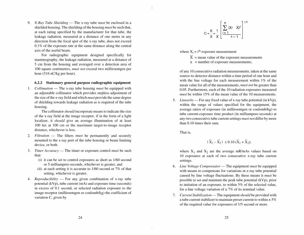
4. Reproducibility — For any given combination of x-ray tubepotential (kVp), tube current (mA) and exposure time (seconds)in excess of 0.1 second, or selected radiation exposure to theimage receptor (milliroentgen or coulomb/kg) the coefficient ofvariation C, given by
where Xi = ith exposure measurement
X = mean value of the exposure measurements n = number of exposure measurements;
of any 10 consecutive radiation measurements, taken at the samesource-to-detector distance within a time period of one hour andwith the line voltage for each measurement within 1% of themean value for all of the measurements, must not be greater than0.05. Furthermore, each of the 10 radiation exposures measuredmust be within 15% of the mean value of the 10 measurements.
5. Linearity — For any fixed value of x-ray tube potential (in kVp),within the range of values specified for the equipment, theaverage ratios of exposure (in milliroentgen or coulomb/kg) totube current-exposure time product (in milliampere-seconds) atany two consecutive tube current settings must not differ by morethan 0.10 times their sum.
That is,
_ _ _ _| X1 – X2 | ≤ 0.10 (X1 + X2);
where X1 and X2 are the average mR/mAs values based on10 exposures at each of two consecutive x-ray tube currentsettings.
6. Line Voltage Compensator — The equipment must be equippedwith means to compensate for variations in x-ray tube potentialcaused by line voltage fluctuations. By these means it must bepossible to set and maintain the peak tube potential (kVp), priorto initiation of an exposure, to within 5% of the selected value,for a line voltage variation of ± 7% of its nominal value.
7. Current Stabilization — The equipment should be provided witha tube current stabilizer to maintain preset current to within ± 5%of the required value for exposures of 1/5 second or more.
2524

Changes in tube potential should not result in a variation oftube current greater than ± 5%.
6.2.3 Mobile radiographic equipmentThe requirements given in sections 6.2.2 (1) to (7) inclusive,
apply. Additional requirements for mobile radiographic equipmentare as follows:
1. Target-to-Skin Distance — The equipment must be equippedwith means to prevent operation at target-to-skin distances of lessthan 30 centimetres.
2. Exposure Control — The exposure switch must be of the dead-man type and must be provided with a cable at least 3 metreslong. A “coiled-type” cable is the most practical for this purpose.
3. Capacitor Discharge Equipment — Capacitor discharge typemobile equipment must be equipped with: (i) a safety shutter or other means to prevent emission of x-
radiation from the exit port of the x-ray tube housingassembly when the exposure switch or timer is notactivated;
(ii) a warning light, or other visual indicator, to indicate thatthe high potential capacitor is charged;
(iii) an electrical meter, or other indicator, to indicate the stateof charge of the high potential capacitor, and
(iv) means to enable the high potential capacitor to be dis-charged to a residual potential difference of less than30 volts, without the production of x-radiation.
6.2.4 Fluoroscopic equipment
1. Collimation — The x-ray tube housing must be equipped withan adjustable collimator which provides stepless adjustment ofthe size of the x-ray field and which must provide the same degreeof shielding towards leakage radiation as is required of the tubehousing.
The maximum size of x-ray field permitted by the collimatorshould not be larger than the useful area of the input phosphoron the image intensifier. The useful beam should be centred onthe input phosphor and the beam margins should be tangential tothe area being viewed. Where a larger area is required for spotfilms an interlock or other positive means must prevent the useof the fluoroscopic mode unless the conditions of this paragraphare met.
2. Direct Bean Absorbers — A primary protective barrier must bepermanently incorporated into the equipment to intercept theentire cross section of the direct beam, for all possible target-to-image receptor distances. The barrier must be so installed that itsremoval from the useful beam causes automatic termination ofthe exposure.
The lead equivalent thickness of the primary protectivebarrier must be at least 2 mm for machines capable of operatingup to 100 kVp. For each additional kilovolt of operating tubepotential an additional 0.01 mm lead equivalent is required.
3. Image Intensification — All fluoroscopic x-ray machines mustbe equipped with an image intensification system. On a mobilefluoroscopic machine the image intensifier must either be anintegral part of the equipment or be interlocked in such a waythat its removal prevents x-rays from being produced.
The image intensification system must be adequatelyshielded so that neither the useful beam nor the scattered radia-tion from the intensifier will produce significant exposure to theoperator or other personnel. The shielding must be such that theexposure rate to an object having a cross-sectional area of100 cm2, with no linear dimension greater than 20 cm, of x-radiation due to transmission of the useful beam through orscattering from the window of the fluoroscopic imaging assem-bly, does not exceed 2 milliroentgen per hour (516 nC/kg/h) at10 centimetres behind the plane of the image receptor, for eachroentgen per minute of entrance exposure rate.
4. Target-to-Skin Distance — Fixed fluoroscopic equipment mustincorporate means to limit the target-to-skin distance to not lessthan 38 centimetres. In the case of a fluoroscopic machine de-signed for special applications that would be impossible at theabove minimum distance, provision may be made for operationat shorter target-to-skin distances; but in no case must thisdistance be less than 20 centimetres.
5. Material Between Patient and Image Receptor — The aluminumequivalent of the table top must not be greater than 1 mm whenmeasured at 100 kVp.
6. Exposure Switch — The fluoroscopic exposure switch must beof a dead-man type.
2726

7. Timer — There must be a cumulative timing device, activated bythe fluoroscopic exposure switch, which requires manual reset-ting. This timer must have a maximum setting not exceeding5 minutes. Whenever a preset time has been reached, it must givea clearly audible signal.
8. Indication of Tube Potential and Current — Electrical meters orother visual indicators must be provided to enable continuousmonitoring by the operator of tube potential and current duringfluoroscopy.
9. Entrance Exposure Rate — At the shortest target-to-skin distancespecified for the equipment, the entrance exposure rate must notexceed 10 roentgen (2.58 mC/kg) per minute for any combina-tion of tube current and potential. With modern equipment mostfluoroscopy can and should be carried out with exposure rates ofless than 5 roentgen (1.29 mC/kg) per minute.
10. Bucky Slot Shielding — Shielding must be provided with theequipment to cover the Bucky Slot. This should provide theequivalent protection of at least 0.5 mm of lead at 100 kVp.
11. Table Shielding — The side of the fluoroscopic table should havean equivalent thickness of at least 0.5 mm of lead at 100 kVp torestrict scattered radiation passing through it.
12. Operator Shielding — To protect the operator from radiationscattered above the table-top, there should be a lead rubber apronof dimensions not less than 45.7 cm × 45.7 cm (18" × 18") Thematerial must have a lead equivalent of not less than 0.5 mm at100 kVp and the apron must be attached to the lower edge of thefluoroscopic screen when the latter is vertical and to the sidewhen the screen is horizontal. The apron may consist of severaloverlapping parts.
In the absence of such a protective apron a retractable leadshield must be incorporated in the equipment to project at least15 cm above the table when in use. It must be mounted on thefront side of the table and have a lead-equivalent thickness of atleast 0.5 mm at 100 kVp.
6.2.5 Photofluorographic equipment
1. Collimation — The equipment must be permanently fitted witha collimator which must confine the beam to the area of the
fluorescent screen. The beam must not be greater than 35 cm ×43 cm (14" × 17") at the screen surface, regardless of thetarget-to-skin distance.
2. Beam Alignment — The photofluorographic camera and x-raytube must be coupled together so that the direct beam alwayscentres on the mid-point of the screen.
3. Gonad Shield — The lower edge of the beam-defining deviceshould be curved to prevent irradiation of the female gonads.
4. Maximum Entrance Exposure — The entrance exposure to apatient must not exceed 200 milliroentgen and should not exceed100 milliroentgen (25.8 microcoulomb/kg) per film.
6.3 Protective clothing6.3.1 Protective body apronsProtective body aprons used for radiographic or fluoroscopic
examinations with peak x-ray tube potentials of up to 150 kVp mustprovide attenuation equivalent to at least 0.5 mm of lead. The leadequivalent thickness of the material used must be permanently andlegibly marked on the apron.
6.3.2 Gonad shieldsContact-type gonad shields used for routine diagnostic radiology
must have a lead equivalent thickness of at least 0.25 mm and shouldhave a lead equivalent thickness of 0.5 mm at 150 kVp. Contact-typegonad shields must be of sufficient size and shape to exclude thegonads completely from primary beam irradiation.
6.3.3 Protective glovesProtective gloves used in fluoroscopy must provide attenuation
equivalent to at least 0.25 mm of lead at 150 kVp. This protectionmust be provided throughout the glove, including fingers and wrist.
6.4 Film cassettesThe proper amount of filtration placed in the useful beam
between the x-ray tube and the patient reduces exposure to the patient.However, any material placed between the patient and the radio-graphic film has the effect of increasing patient exposure. With this
2928

in mind, the front panel of the film cassette must not exceed analuminum equivalence thickness of 1.0 mm and should not exceed analuminum equivalence thickness of 0.5 mm.
Film cassettes must be completely light-tight. As soon as thematerial used for achieving light-tightness becomes worn and lightleakage occurs, either the material or the cassette should be replaced.
It is also important to have good film-screen contact; thereforescreens should be cleaned regularly and their contact with the filmchecked.
7. Darkroom and film processing
The x-ray exposure necessary to produce a radiography of satis-factory diagnostic quality, commensurate with minimum exposure tothe patient, depends not only on the exposure technique and film-screen combination employed but also on the handling and processingof the film. These require a good darkroom and proper developingtechniques.
7.1 DarkroomMost modern x-ray departments use automatic film processors
for film development. Nevertheless, good darkrooms are still anessential requirement whether they be used for manual processing offilms or for loading automatic film processors. While specific detailsmay vary from installation to installation all darkrooms should in-clude certain basic features:
1. The room must be completely light-tight.
2. If adjacent to a radiography room, the darkroom must be ade-quately shielded to ensure that exposure of personnel and film tox-radiation does not occur.
3. The darkroom should be designed to incorporate a lockable door,double doors or a blackened maze entrance to ensure lighttightness when undeveloped films are being handled.
4. A warning light should be located outside the darkroom, at theentrance, to indicate when the room is in use.
5. Safelights fitted with bulbs of correct intensity must be providedabove the work areas within the darkroom. The safelights musthave filters appropriate to the specifications of the film used andmust be positioned at the proper distances from work areas.
3130
7.2 Film processingImproper or careless processing of exposed radiographic films
can cause films of poor diagnostic quality and consequently thechance of wrong diagnosis or requests for repeat exposures. Toachieve full development of a film which has been exposed, usingcorrect radiographic technique factors, the film must be processed inchemically fresh developer, at proper temperature and for sufficienttime to ensure that the silver in exposed silver halide crystals in thefilm emulsion is completely reduced. If this is not done the blackeningof the film will not be optimum and the tendency will be to increaseradiation exposure to achieve proper image density.
To ensure proper processing of films certain basic recommenda-tions should be followed:
1. Manufacturers’ recommendations with respect to strength ofsolutions, temperature and time must be followed to ensureoptimum development.
2. Developing solutions should be replenished as necessary andshould be changed regularly, as required.
3. Developing solutions should be monitored regularly. Even un-used developer deteriorates with time. Developer should not beused when it becomes necessary to develop significantly longerthan the recommended times in order to obtain optimum filmdensity.
7.3 Film storageUnexposed radiographic films must be stored in such manner that
they are shielded from stray radiation. Storage should be providedsuch that no film receives more than 0.2 milliroentgen of strayradiation before use. The amount of shielding required will dependon the storage time and on the workload of the facility. It can bedetermined from the table in Appendix IV.
Films should be stored on end in a cool, dry area.
8. Procedures to reduce doseto x-ray personnel
The guidelines and procedures outlined in this section are pri-marily directed toward occupational health protection. However,adherence to these will also, in many instances, provide protection tovisitors and other individuals in the vicinity of an x-ray facility. Thesafe work practices and procedures for using various types of x-rayequipment should be regarded as a minimum, to be augmented withadditional requirements, when warranted, to cover special circum-stances in particular facilities.
To achieve optimum safety, radiologists and radiographers mustmake every reasonable effort to keep exposures to themselves and toother personnel as far below the limits specified in Appendix I asreasonably achievable.
8.1 General recommendations1. An x-ray room must not be used for more than one radiological
investigation simultaneously.
2. Except for those persons whose presence is essential, no personmust be in the x-ray room when the exposure is carried out.
3. Personnel must at all times keep as far away from the useful beamas is practicable. Exposure of personnel to the useful beam mustnever be allowed unless the beam is adequately attenuated by thepatient and by protective clothing or screens.
4. All personnel must take full advantage of the protective devicesavailable.
5. Operators should remain inside the control booth or behindprotective screens when making an x-ray exposure. In caseswhere there are reasons that make this impractical, protectiveclothing must be worn.
6. When there is a need to support children or weak patients,holding devices should be used. If parents, escorts or otherpersonnel are called to assist, they must be provided with
3332

protective aprons and gloves, and be positioned so as to avoid theuseful beam. No one person should regularly perform theseduties.
7. When a lead equivalent protective apron is worn, the personneldosimeter must be worn under the apron. If extremities are likelyto be exposed to significantly higher doses, additional extremitymonitors should be worn.
8. All operators of x-ray equipment, together with personnel(e.g.nurses) who routinely participate in radiological procedures,and others likely to receive a radiation dose in excess of 1/20thof the maximum permissible specified in Appendix I, must wearpersonnel dosimeters.
9. All entrance doors to an x-ray room, including patient cubicleand preparation room doors, should be kept closed while a patientis in the room.
10. X-ray machines which are energized and ready to produce radia-tion must not be left unattended.
11. Where radiation doses in excess of 5% of the maximum permis-sible specified in Appendix I are being received regularly by anyone person, appropriate remedial steps must be taken to improvetechniques and protective measures.
12. X-ray equipment must only be operated by, or under the directsupervision of, qualified individuals. (See sections 3.2 and 3.3).
13. An x-ray housing must not be held by hand during operation.
8.2 Recommendations for operation of radiographic units
1. The x-ray exposure should, as a general rule, be controlled fromthe control panel located inside the control booth or behind ashielded wall. In the case of special techniques where the opera-tor is required to control the exposure while at the side of thepatient, appropriate protective clothing must be worn.
2. The operator must have a clear view of the patient during everyexposure and be able to communicate with the patient and/orattendants without leaving the control booth.
3. Cassettes must never be held by hand during an exposure.
8.3 Recommendations foroperation of fluoroscopic units
1. All persons, with the possible exception of the patient, requiredto be in the room during a fluoroscopic procedure should wearprotective aprons. Lead shields or curtains mounted on thefluoroscopic unit must not be considered a sufficient substitutefor the wearing of protective clothing.
2. Protective gauntlets should be worn by the radiologist duringpalpation in every fluoroscopic examination. During fluoros-copy, palpation with the hand should be kept to a minimum.
3. During fluoroscopy and spotfilm operation associated withfluoroscopic operation, where personnel are required to be at theside of the patient, appropriate protective clothing must be wornby these personnel.
4. All fluoroscopic examinations should be carried out as rapidlyas possible and with minimum dose-rates and x-ray field sizes.
5. Direct-viewing fluoroscopy must not be carried out; image-intensified fluoroscopy must be used.
8.4 Recommendations foroperation of mobile units
1. Mobile units must be used only if the condition of the patient issuch as to make it inadvisable for the examination to be carriedout with a stationary unit in the main x-ray department.
2. During operation, the primary beam should be directed fromoccupied areas if at all possible, and every effort must be madeto ensure that this beam does not irradiate any other persons inthe vicinity of the patient.
3. The operator must stand at least 3 metres from the x-ray tube andout of the direct beam.
4. The operator must be shielded when exposures are made.
3534
5. In a capacitor discharge unit after an x-ray exposure has beenmade there is a residual charge left in the capacitors. This residualcharge can give rise to a “dark current” and result in x-rayemission even though the exposure switch is not activated. There-fore, the residual charge must be fully discharged before the unitis left unattended.
8.5 Recommendations foroperation of photofluorographic units
Photofluorographic x-ray machines in general can give signifi-cantly higher patient doses than conventional diagnostic machines,therefore their use is severely restricted in Canada. When, subject tothe guidelines outlined in section 9.4, the use of such units is justified,the following recommendations apply:
1. Only the operator and the patient should be in the room or vehiclein which the unit is installed when an exposure is made.
2. When a photofluorographic unit is mounted in a vehicle appro-priate steps must be taken to ensure that persons awaiting exami-nation and personnel are protected from exposure to x-radiation.Such persons should be kept well clear of the vehicle whenexposures are being made.
8.6 Recommendations forspecial radiological procedures
1. Cystoscopic radiography, Hystero-salpingography, NeedleBiopsies of the Lung, Transhepatic Needle Cholangiography,Pancreatography, and other similar procedures. In these proce-dures the radiologist and other personnel in the vicinity of thepatient can be subjected to appreciable scattered radiation fromthe patient when the x-ray beam is on. Therefore, the radiologistand other personnel should wear protective glasses and clothingand should remain as far away from the patient as practicable,unless adequate scatter shields can be incorporated into the x-rayequipment. The protective devices (e.g., shielded panels, leadeddrapes, extended collimator cones, etc.) provided with the x-rayequipment should be used whenever they do not interfere undulywith the diagnostic procedures. The smallest x-ray field consis-tent with the procedure should be used.
2. Angiography. Angiography is potentially one of the sources ofgreatest exposure to personnel in diagnostic radiology, since itrequires the presence of a considerable number of personnelclose to the patient and involves fluoroscopy for extended periodsof time and multiple radiographic exposures. For such proce-dures all personnel must be aware of the radiation hazardsinvolved and make every effort to adhere to the recommendationsbelow:(1) Full use must be made of the protective devices provided
with x-ray equipment (e.g., shielded panels, leaded drapes,bucky slot covers, etc.).
(2) All personnel must wear protective clothing and personneldosimeters. Protective glasses should also be worn.
(3) All personnel who are not required to be immediatelyadjacent to the patient during the procedure must standback as far as possible from the patient and, if at allpossible, should stand behind a protective shield.
(4) Where indicated and feasible, special shields in additionto the protective devices provided with the machine shouldbe used.
3736

9. Procedures for minimizingdose to patients
The largest single contributor of man-made radiation exposureto the population is medical diagnostic radiology. In total exposure,medical use of x-rays accounts for more than 90% of the totalman-made radiation exposure to the general population. It is generallyagreed by experts in the scientific community that medical x-rayexposure can be reduced substantially with no decrease in the valueof medical information derived.
To accomplish this reduction, it is essential that patients notbe subjected to unnecessary radiological examinations and, whenradiological procedures are required, it is essential that patients beprotected from excessive exposures during the examination.
The recommendations and procedures for the protection of thepatient outlined in this section are directed toward the physician, theradiologist and the operator. They are intended to provide guidelinesfor elimination of unnecessary radiological procedures and for mini-mizing exposures to patients when radiological examinations areindicated. Included also are recommended upper limits on patientexposures for certain common radiographic examinations.
9.1 Guidelines for the prescription of diagnostic x-ray examinations
The medical practitioner is in a unique position to reduce un-necessary radiation exposure to the patient by ensuring that allexaminations are clinically justified. The practitioner can achieve thisby adhering, as much as possible, to certain basic recommendations.These are as follows:
1. The prescription of an x-ray examination of a patient should onlybe based on a clinical evaluation of the patient and should be forthe purpose of obtaining diagnostic information.
2. Routine or screening examinations, such as for preemploymentphysical examinations, tuberculosis screening, mass mam-mographic screening, etc., in which there is no prior clinicalevaluation of the patient, should not be prescribed.
3. It should be determined whether there have been any previousx-ray examinations which would make further examinationunnecessary, or allow for the ordering of an abbreviated exami-nation. Relevant previous radiographs or reports should beexamined along with a clinical evaluation of the patient.
4. When a patient is transferred from one physician or hospital toanother any relevant radiographs or reports should accompanythe patient and should be reviewed by the consulting physician.
5. When prescribing a radiological examination, the physicianshould specify precisely the clinical indications and informationrequired.
6. The number of radiographic views, required in an examination,should be kept to the minimum practicable, consistent with theclinical objectives of the examination.
7. In prescribing x-ray examinations of pregnant or possibly preg-nant women, full consideration should be taken of the conse-quences of foetal exposure.
8. If a radiograph contains the required information, repeat expo-sures should not be prescribed simply because the radiographmay not be of the “best” diagnostic quality.
9. Specialized studies should be undertaken only by, or in closecollaboration with, a qualified radiologist.
10. Medical practitioners should not operate x-ray equipment, or beresponsible for the use of such equipment.
11. A patient’s clinical records should include details of x-ray exami-nations carried out.
9.2 Guidelines for radiography of pregnant women
Radiography of the pelvic area of a woman known to be pregnantsimultaneously irradiates the patient’s gonads and the whole body ofthe foetus. Irradiation of the unborn foetus increases the infant’s risk
3938

of somatic effects and also increases the risk of genetic effects insubsequent offspring. Therefore, every effort should be made to avoidunnecessary irradiation of any woman known to be, or who might bepregnant. This is particularly important during the earliest stages ofpregnancy when the potential for radiation damage of the rapidlydividing tissues is the greatest. Clearly, however, in spite of thepossibility of radiation damage, if a radiological examination isrequired for the diagnosis or management of an urgent medicalproblem it must be done, irrespective of whether the patient may ormay not be pregnant.
The following recommendations apply to x-ray examinationsinvolving pregnant or potentially pregnant women:
1. Radiography of the pelvic area in women of child-bearing ageshould be undertaken in the ten-day period following the onsetof menstruation, since the risk of pregnancy is very small duringthis period.
2. Only essential investigations should be taken in the case ofpregnant or suspected pregnant women.
Elective radiography of the abdominal and pelvic area inpregnant women must be avoided. (“Elective” is taken to meanan examination of the abdomen and pelvis which does notcontribute to the diagnosis or treatment of a women in relationto her immediate illness.)
3. Pregnant women or women who may be pregnant must notbe accepted for chest photofluorographic (mass radiographic)examinations.
4. When radiography of the pelvic area or abdomen is required, theexposure must be kept to the absolute minimum necessary andfull use must be made of gonadal shielding and other protectiveshielding if the clinical objectives of the exmaination will not becompromised.
5. If a radiographic examination of the foetus is required the proneposition should be used. This has the effect of shielding the foetusfrom the softer x-rays and hence reducing the foetal dose.
6. Radiography should not be used for the determination of abnor-mal presentations of the foetus, or for placenta localizations.Other techniques such as ultrasonography are better suited forthis purpose.
7. Radiography of the chest, extremities, etc., of a pregnant woman,for valid clinical reasons, should only be carried out using awell-collimated x-ray beam and with proper regard for shieldingof the abdominal area.
9.3 Guidelines for radiographic examination of the breast (Mammography)
For mammographic x-ray equipment see Safety Code 33“Radiation Protection in Mammography”.
9.4 Radiological chest screening1. The use of mass radiological screening should only be con-
sidered in areas of high incidence of tuberculosis or in specialpopulation groups who may be particularly susceptible to lungdisease. Selection of population groups for x-ray screeningshould be based upon the probability of discovering a significantnumber of cases of cardiopulmonary disease and on the avail-ability of full follow-up facilities for individuals requiring treat-ment.
2. Mass x-ray screening of the general population for tuberculosisand other chest diseases must not be carried out.
3. Routine hospital admission chest x-rays should only be taken inidentified high risk groups.
4. Chest x-rays should not be required as a routine part of apre-employment medical check-up or for admission to educa-tional institutions.
5. Since photofluorographic x-ray machines require a higher levelof x-ray exposure than do convential radiographic machines toproduce a film and since the yield of significant information islow, photofluorographic x-ray machines must not be used forchest examinations in place of conventional machines, andshould not be used for mass screening when conventionalmachines are available.
4140

9.5 Guidelines for carrying out x-ray examinations
Next to elimination of unnecessary x-ray examinations, the mostsignificant factor in reducing patient exposure is ensuring that anecessary examination is performed with good technique. It is possi-ble, for example, to obtain a series of diagnostically-acceptableradiographs and have the patient exposure vary widely because ofchoice of technique factors used. It is the responsibility of the operatorand radiologist to be aware of this and to know how to carry out aprescribed examination with the lowest possible exposure to thepatient.
The recommendations that follow are intended to provide guid-ance to the operator and radiologist in exercising their responsibilitytowards reduction of patient exposure.
9.5.1 General recommendations
1. The operator must not perform any examination which has notbeen prescribed by a physician responsible for the patient.
2. The exposure of the patient must be kept to the lowest practicablevalue, consistent with clinical objectives and without loss ofessential diagnostic information. To achieve this, techniquesappropriate to the equipment available should be used.
3. Particular care, consistent with the recommendations of Section9.2, must be taken when radiological examinations of pregnantor potentially pregnant women are carried out.
4. The x-ray beam must be well-collimated to restrict it as much asis practicable to the area of diagnostic interest.
5. The x-ray beam size must be limited to the size of the imagereceptor or smaller.
6. The x-ray beam should not be directed towards the gonads unlessit is absolutely essential, in which case gonad shielding must beused whenever the value of the examination is not impaired bysuch use. Guidelines on the use of gonal shielding are given insection 10 of this Code.
7. Shielding should be used where appropriate and practicable tolimit the exposure of body tissues. It is particularly important thatspecial effort to be made to protect the blood-forming organs,gonads and thyroids of children.
8. The target-to-skin distance should be as great as possible, con-sistent with good radiographic technique.
9. For very young children, special devices should be employed torestrict movement.
10. Full details of the radiological procedures carried out should benoted on the patient’s clinical records.
9.5.2 Recommendations for radiographic procedures
1. The edges of the x-ray beam should be seen on all x-ray films toensure that no more than the desired area has been irradiated. Thefilm size used should be as small as possible, consistent with thediagnostic objectives of the examination.
2. Screen-type film should not be used for non-screen techniquesbecause it is less sensitive to direct x-radiation than non-screenfilm.
3. The fastest film or intensifying screen-film combination, consis-tent with diagnostically-acceptable results, should be used.When highest definition is not required a high-speed film-screencombination should be used.
X-ray intensifying screens made from rare earth phosphorsshould be used where appropriate. Exposure reductions in excessof 50%, compared to conventional calcium tungstate systems,are possible using the rare earth-type intersifying screens and thefilms developed for use with such screens. These reductionsresult from greater x-ray absorption and increased conversionefficiencies of the new phosphors — the rare earth systems havea conversion efficiency of x-rays to light of 15-20%, comparedto approximately 5% for calcium tungstate systems.
4. To ensure that patient exposure is kept to a minimum, consistentwith image quality, full advantage should be taken of a combi-nation of techniques, such as:(a) use of an antiscatter grid or air gap between the patient and
the image receptor;
4342

(b) use of the optimum focus-to-film distance appropriate tothe examination;
(c) use of the highest kilovoltage which produces films ofgood quality;
(d) use of automatic exposure control devices designed to keepall exposures and repeat exposures to a minimum.
5. The radiographer should see the films after processing in orderto verify that the techniques being used are producing diagnosticquality films and that the x-ray equipment is functioning cor-rectly.
6. To avoid the necessity of retakes, it is particularly importantbefore taking a long series of films that a single preliminary filmof the series should be taken and processed to verify correctnessof settings.
7. While maximum permissible levels of exposure have beendefined for radiation workers and the general population, nospecific permissible levels have been recommended, to date, forpatients undergoing diagnostic x-ray procedures. For patients therisk involved in the exposure must always be weighed against themedical requirement for accurate diagnosis. However, from dataobtained in the Nationwide Evaluation of X-Ray Trends(N.E.X.T.) program, it is now feasible to recommend upper limitson patient skin entrance exposure, for routine, non-specialty,radiographic examinations. For a reference patient, having theanthropometrical characteristics shown in Table 1, the skin en-trance exposure (without backscatter) should not exceed thevalues indicated in Table 2.
Table 1Anthropometrical Characteristics of the Reference Patient
Body Part Thickness (cm)
Head (lateral) 15
Neck (A/P) 13
Chest (P/A) 23
Abdomen (A/P) 23
Foot (D/P) 8
Table 2Recommended Upper Limits on Skin Entrance Exposure
Examination (Projection) ESE (mR)
Chest (P/A) 20
Skull (Lateral) 170
Abdomen (A/P) 450
Cervical Spine (A/P) 120
Thoracic Spine (A/P) 400
Full Spine (A/P) 250
Lumbo-Sacral Spine (A/P) 500
Retrograde Pyelogram (A/P) 500
Feet (D/P) 200
Note: In practice, it should be feasible to have actual skin entranceexposures substantially lower than these limits.
9.5.3 Recommendations for fluoroscopic procedures
1. In view of the relatively high exposure that results from fluoros-copy, such procedures should only be carried out when anequivalent result cannot be obtained from radiography. Fluoros-copy must not be used as a substitute for radiography.
2. Flurorscopy must only be carried out by, or under immediatesupervision of, a radiologist or physician properly trained influoroscopic procedures.
3. All fluoroscopic procedures should be carried out as rapidly aspossible with the smallest practical x-ray field sizes.
4. The exposure rate used in fluoroscopy should be as low aspossible and must not exceed 10 roentgens (2.58 mC/kg) perminute at the position where the central axis of the x-ray beamenters the patient. With modern equipment, most fluoroscopicprocedures can be readily carried out with exposure rates of lessthan 5 roentgens (1.29 mC/kg) per minute.
5. Image intensification must be used in order to reduce patientexposure. Image intensifiers can significantly reduce bothexposure rate and exposure time. However, the operator must
4544
monitor the x-ray tube current and voltage on equipment withautomatic brightness control, since both can rise to high valueswithout the knowledge of the operator, particularly if the gain ofthe intensifier is decreased.
6. Television monitoring should be used in conjunction with theimage intensifier.
7. Mobile fluoroscopic equipment should only be used for exami-nations where it is impractical to transfer patients to a permanentfluoroscopic installation.
8. Cinefluorography produces the highest patient doses in diagnos-tic radiology because the x-ray tube currents and potentials usedare generally higher than those used in fluoroscopy. Therefore,this technique should not be used unless significant medicalbenefit is expected.
9.5.4 Recommendations for photofluorographic procedures
1. The x-ray beam must be restricted to the area of the fluorescentscreen and should be limited to the minimum size consistent withclinical requirements.
2. Appropriate steps must be taken to exclude or shield the gonadsfrom the direct beam.
3. The performance of the equipment must be monitored routinely.Special emphasis should be placed on the speed of the opticalsystems used. These should be as fast as possible and should bereplaced when noticeable deterioration in performance occurs.
9.5.5 Recommendations for mammographyFor mammographic x-ray equipment see Safety Code 33
“Radiation Protection in Mammography”.
9.5.6 Recommendations for special procedures
1. Significant exposure to the patient’s eyes can result during neuro-logical examinations, such as carotid angiography. In projectionswhere it does not interfere with the diagnostic informationsought, eye shielding should be used.
2. During cardiac catheterization and angiography significantexposure of the patient’s thyroid gland can occur. Therefore,appropriate shielding should be used whenever possible.
4746

10. Guidelines for reduction of gonad dose
Ionizing radiation has the ability to produce gene mutations andchromosome aberrations in cells. When such effects occur in repro-ductive cells, undesirable mutations may be transmitted to subsequentgenerations. These genetic effects, once imparted to the genetic poolof a population, may take generations to be eliminated.
Medical x-ray diagnosis is, at present, the major contributor ofgonadal radiation exposure to the population. By reducing the gonaddose to individual patients one can, in fact, make a significant contri-bution toward the reduction of the genetically significant dose to thepopulation.
It is generally presumed that there is no threshold dose belowwhich genetic effects cannot occur. Therefore, it is important that evensmall radiation exposures to be gonadal areas of patients be avoided,unless such exposures can be shown to be medically necessary.
10.1 Recommendations for reducing gonad dose to the patient
Radiologists and radiographers must pay special attention to fourfactors that are important for reducing gonad dose to the patient:
1. Correct collimation of the x-ray beam. — It is not sufficientmerely to limit the beam to the size of the image receptor. Careshould be taken to further restrict the beam to the region of thepatient’s body that is of diagnostic interest. Irradiation of any partof the body outside that region contributes nothing to the objec-tive of the examination and only increases dose both to the bodyand the gonads.
2. Gonad shielding. — Appropriate use of specific area gonadshielding is strongly advised when: (i) the gonads, of necessity, lie within, or are in close
proximity to, the primary x-ray beam; (ii) the patient has reasonable reproductive potential; and (iii) clinical objectives will not be compromised.
3. Appropriate selection of technique factors. — An appropriateselection of tube voltage, current and filtration is particularlyimportant for diagnostic procedures in which the gonads liewithin or near the primary x-ray beam. For example, in fluoros-copy, use of higher tube voltage and filtration and lower tubecurrent will almost always reduce the gonad dose.
4. Sensitivity of imaging systems. — The gonad dose is inverselyproportional to the sensitivity of the imaging system. Thus,doubling the sensitivity halves the gonad dose; conversely, halv-ing the sensitivity doubles the gonad dose. It is, therefore, veryimportant to maintain the sensitivity of the imaging system at itsoptimum value and to be alert for any significant deterioration.
10.2 Recommendations for reducing gonad dose to operators
Adherence to the safe use procedures specified in Section 8 ofthis Safety Code will ensure that gonad dose to radiologists andradiographers is kept to the minimum practicable.
4948
APPENDIX IRecommended dose limits of
ionizing radiation
For the purpose of radiation protection, individuals may beclassified in one of two categories: those exposed to radiation fromman-made sources during their work (radiation workers), and others.The recommended dose limits are given for both categories in thefollowing table. These dose limits are based on the latest recommen-dations of the International Commission on Radiological Protection(ICRP) as specified in ICRP Publication 60.
It must be noted that the dose limits for radiation workers applyonly to irradiation resulting directly from their occupation and do notinclude radiation exposure from other sources, such as medicaldiagnosis and background radiation.
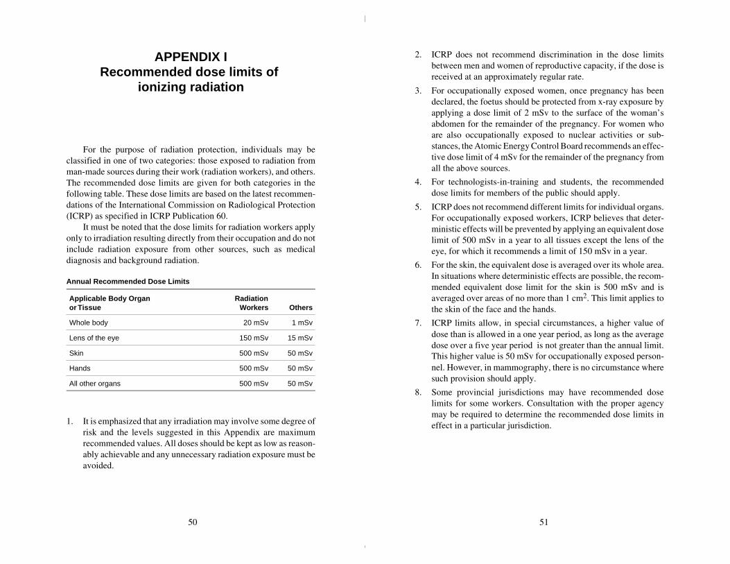
Annual Recommended Dose Limits
Applicable Body Organ or Tissue
RadiationWorkers Others
Whole body 20 mSv 1 mSv
Lens of the eye 150 mSv 15 mSv
Skin 500 mSv 50 mSv
Hands 500 mSv 50 mSv
All other organs 500 mSv 50 mSv
1. It is emphasized that any irradiation may involve some degree ofrisk and the levels suggested in this Appendix are maximumrecommended values. All doses should be kept as low as reason-ably achievable and any unnecessary radiation exposure must beavoided.
2. ICRP does not recommend discrimination in the dose limitsbetween men and women of reproductive capacity, if the dose isreceived at an approximately regular rate.
3. For occupationally exposed women, once pregnancy has beendeclared, the foetus should be protected from x-ray exposure byapplying a dose limit of 2 mSv to the surface of the woman’sabdomen for the remainder of the pregnancy. For women whoare also occupationally exposed to nuclear activities or sub-stances, the Atomic Energy Control Board recommends an effec-tive dose limit of 4 mSv for the remainder of the pregnancy fromall the above sources.
4. For technologists-in-training and students, the recommendeddose limits for members of the public should apply.
5. ICRP does not recommend different limits for individual organs.For occupationally exposed workers, ICRP believes that deter-ministic effects will be prevented by applying an equivalent doselimit of 500 mSv in a year to all tissues except the lens of theeye, for which it recommends a limit of 150 mSv in a year.
6. For the skin, the equivalent dose is averaged over its whole area.In situations where deterministic effects are possible, the recom-mended equivalent dose limit for the skin is 500 mSv and isaveraged over areas of no more than 1 cm2. This limit applies tothe skin of the face and the hands.
7. ICRP limits allow, in special circumstances, a higher value ofdose than is allowed in a one year period, as long as the averagedose over a five year period is not greater than the annual limit.This higher value is 50 mSv for occupationally exposed person-nel. However, in mammography, there is no circumstance wheresuch provision should apply.
8. Some provincial jurisdictions may have recommended doselimits for some workers. Consultation with the proper agencymay be required to determine the recommended dose limits ineffect in a particular jurisdiction.
50 51

APPENDIX IIShielding guides for diagnostic x-ray
installations
To determine the shielding necessary for a diagnostic x-rayinstallation certain preliminary information is essential. The requiredthickness of shielding can be calculated using the formulae containedin this Appendix, in conjunction with Figures 1 to 3. In both instancesanswers to the following questions are required:
1. What is the distance between the nearest point of the area to beshielded and the mean operational position of the x-ray tube?
2. Is the area to be designated as a controlled or uncontrolled area,i.e. will the area be occupied by radiation workers (subject to thelimit of 20 mSv per year) or non-radiation workers (subject tothe limit of 1 mSv per year)?
3. What will be/is the occupancy factor (T) of the area? Theoccupancy factor is defined as the time an area is normallyoccupied, expressed as a fraction of the working week. (If notaccurately known, use Table 1).
4. Will the intervening shield between the x-ray tube and theoccupied area act as a primary or secondary protective barrier,i.e. will the barrier be required to attenuate the direct useful beamor stray (leakage and scattered) radiation only?
5. What will the use factor (U) of the required protective barrier?The use factor is defined as the fraction of the operational timeduring which the useful beam will be/is directed at the barrier orarea under consideration. (If not accurately known, use Table 2).
6. What will be/is the workload (W) of the x-ray unit? The work-load indicates the operational time of an x-ray machine ex-pressed in terms of milliampere-minutes per week.
7. What will be/is the maximum and average operating tube poten-tial, and output?
Table 1Occupancy Factors
The occupancy factors given in this table are for use as a guide inplanning shielding for facilities where actual occupancy factor data arenot available.
T = 1(Fulloccupancy)
Control space, offices, nurses’ stations, corridorsand waiting spaces large enough to hold desks,wards and patients’ rooms, darkrooms, workroomsand shops, rest rooms and lounge rooms routinelyused by occupationally exposed personnel, livingquarters, children’s play areas, and occupiedspace in adjoining buildings.
T = 1/4(Partialoccupancy)
Corridors too narrow for desks, utility rooms, restrooms and lounge rooms not used routinely byoccupationally exposed personnel, elevators usingoperators, unattended parking lots, patients’dressing rooms.
T = 1/16(Occasionaloccupancy)
Closets too small for future occupancy, toilets notused routinely by occupationally exposedpersonnel, stairways, automatic elevators,sidewalks, streets.
Table 2Use Factors for Primary Protective Barriers*
The use factors given in this table are for use as a guide in planningshielding for facilities where actual use factor data are not available.
U = 1(Full use)
Floors of radiation rooms, walls containing avertical cassette holder; any other walls, doors orceiling areas routinely exposed to the useful beam.
U = 1/4(Partial use)
Doors and wall areas of radiation rooms notroutinely exposed to the useful beam.
U = 1/16(Occasionaluse)
Ceiling areas of radiation rooms not routinelyexposed to the useful beam.
*Note: The use factor for secondary protective barriers is always taken tobe 1.
52 53

Table 3Typical Workloads (W) For Busy Department
DailyPatient
Load
WorkloadmA-min/week
#100 kVp 125 kVp 150 kVp
Chest(36 cm × 43 cm) (14" × 17")
60 150 — —
Cystoscopy 8 600 — —
Fluoroscopy includingspot filming 24 1500 600 300
Fluoroscopy withoutspot filming 24 1000 400 200
Fluoroscopy withimage intensificationincluding spot filming
24 750 300 150
General Radiography 24 1000 400 200
Special Procedures 8 700 280 140
Table 4Half-Value Layers and Tenth-Value Layers for Heavily Filtered X-Radiation Under Broad-Beam Conditions
TubePotential
Attenuation Material
Lead (mm) Concrete (cm)
kVp HVL TVL HVL TVL
50 0.06 0.17 0.43 1.5
70 0.17 0.52 0.84 2.8
85 0.22 0.73 1.25 4.5
100 0.27 0.88 1.60 5.3
125 0.28 0.93 2.00 6.6
150 0.30 0.99 2.24 7.4
200 0.52 1.70 2.50 8.4
250 0.88 2.90 2.80 9.4
300 1.47 4.80 3.10 10.4
Table 5Commercial Lead Sheets
ThicknessWeight in Pounds for
1 Square Foot Section
InchesMillimetre
EquivalentNominal
WeightActualWeight
1/64 0.40 1 0.92
3/128 0.60 1½ 1.38
1/32 0.79 2 1.85
5/128 1.00 2½ 2.31
3/64 1.19 3 2.76
7/128 1.39 3½ 3.22
— 1.50 — 3.48
1/16 1.58 4 3.69
5/64 1.98 5 4.60
3/32 2.38 6 5.53
— 2.50 — 5.80
— 3.00 — 6.98
1/8 3.17 8 7.38
5/32 3.97 10 9.22
3/16 4.76 12 11.06
7/32 5.55 14 12.90
1/4 6.35 16 14.75
1/3 8.47 20 19.66
2/5 10.76 24 23.60
1/2 12.70 30 29.50
2/3 16.93 40 39.33
1 25.40 60 59.00
Notes:1. The density of commercially rolled lead is 11.36 g. cm-3.
2. The commercial tolerances are ± 0.005 inches for lead up to 7/128 and± 1/32 heavier sheets.
3. Lead sheet less than 1/32 inch thick is frequently more expensive thanheavier sheet in cost of material and cost of installation.
54 55

Figure 1Attenuation in lead of x-rays generated at 50 to 300 kVp.
Figure 1(Cont’d)
56 57
LEAD, millimetres
0 5 10 15 20
0.01
0.00001
0.0001
0.1
10.0
0.001
LEAD, millimetres
0.00001
0.0001
0.001
0.01
0.1
1.0
0 1 2 3 4
1.0

Figure 2Attenuation in concrete of x-rays generated at 50 to 300 kVp.
Formulae for calculation ofshielding requirements
The thickness of shielding required can be calculated usingthe formulae given below. This method requires knowing theWorkload W, in mA-min. per week, the Use Factor U, the occupancyfactor T and the distance d, in metres, from the source to the occupiedarea. Typical values of T, U and W are given in Tables 1 to 3respectively.
This method involves computation of an average value for theexposure per unit workload at unit distance, K, (in R/mA-min at1 metre) and then using the curves shown in Figures 1 and 2 and todetermine the thickness of lead or concrete required to reduce radia-tion levels to the required value.
1. Primary protective barriersFor primary protective barriers the value of K can be computed
from the following equation:
K =Pd2
WUT. . . . . . . . . . . . . . . . . . . . . .. . . . . . . . . . . . . . (1)
where: P = maximum permissible weekly exposure rate ex-pressed in R/week. or controlled areas P = 0.04R/week; for uncontrolled areas P = 0.002 R/week.
d = distance in metres from the target to the primary area.
W = workload in mA-min/week.
U = use factor.
T = occupancy factor.
K = exposure per unit workload at unit distance, in R/mA-min at 1 metre.
Example: Determine the thickness of primary barrier required toprotect a controlled area 3 metres from the target of a 150 kVpdiagnostic unit having a weekly workload of 2000 mA-min. The wallhas a use factor of 1 and the occupancy factor of the area beyond thewall is 1.
58 59
CONCRETE, millimetres
K,R
per
mA
min
at1
m
0 10 20 30 40 50
0.01
0.00001
0.0001
0.1
10.0
0.001
1.0
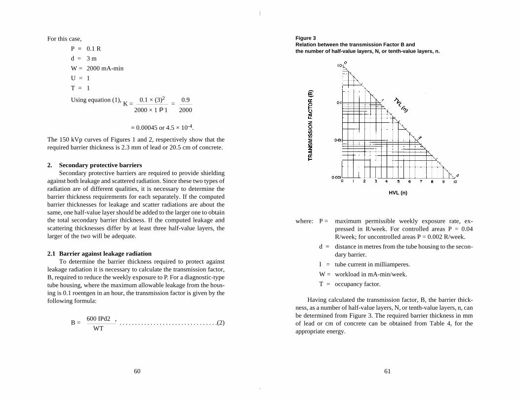
For this case,
P = 0.1 R
d = 3 m
W = 2000 mA-min
U = 1
T = 1
Using equation (1), K =
0.1 × (3)2 =
0.9
2000 × 1 P 1 2000
= 0.00045 or 4.5 × 10⁻⁴.
The 150 kVp curves of Figures 1 and 2, respectively show that therequired barrier thickness is 2.3 mm of lead or 20.5 cm of concrete.
2. Secondary protective barriersSecondary protective barriers are required to provide shielding
against both leakage and scattered radiation. Since these two types ofradiation are of different qualities, it is necessary to determine thebarrier thickness requirements for each separately. If the computedbarrier thicknesses for leakage and scatter radiations are about thesame, one half-value layer should be added to the larger one to obtainthe total secondary barrier thickness. If the computed leakage andscattering thicknesses differ by at least three half-value layers, thelarger of the two will be adequate.
2.1 Barrier against leakage radiationTo determine the barrier thickness required to protect against
leakage radiation it is necessary to calculate the transmission factor,B, required to reduce the weekly exposure to P. For a diagnostic-typetube housing, where the maximum allowable leakage from the hous-ing is 0.1 roentgen in an hour, the transmission factor is given by thefollowing formula:
B = 600 IPd2 ,
. . . . . . . . . . . . . . . . . . . . . . . . . . . . . . . .(2) WT
Figure 3Relation between the transmission Factor B and the number of half-value layers, N, or tenth-value layers, n.
where: P = maximum permissible weekly exposure rate, ex-pressed in R/week. For controlled areas P = 0.04R/week; for uncontrolled areas P = 0.002 R/week.
d = distance in metres from the tube housing to the secon-dary barrier.
I = tube current in milliamperes.
W = workload in mA-min/week.
T = occupancy factor.
Having calculated the transmission factor, B, the barrier thick-ness, as a number of half-value layers, N, or tenth-value layers, n, canbe determined from Figure 3. The required barrier thickness in mmof lead or cm of concrete can be obtained from Table 4, for theappropriate energy.
60 61
HVL (n)

Example: Determine the thickness of barrier required to protect acontrolled area 2 metres from the housing of a 200 kVp diagnosticunit having a weekly workload of 2000 mA-min. Assume that thetube operates at 5 mA and that the area in question has an occupancyfactor of 1. For this case,
P = 0.1 R
d = 2 m
W = 2000 mA-min
T = 1
I = 5 mA
Using equation (2),
B = 600 × 5 × 0.1 × (2)2
= 1200
=
0.6 2000 × 1 2000
From Figure 3, a transmission 0.6 corresponds to 0.13 TVL’s or0.7 HVL’s. From Table 4 the HVL for 200 kVp is 0.52 mm lead or2.5 cm concrete. Thus the required barrier thickness for protectionagainst leakage radiation is
(0.7 × 0.52) = 0.36 mm lead
(0.7 × 2.5) = 1.75 cm concrete
2.2 Barrier against scatter radiationScattered radiation has a much lower exposure rate than that of
the incident beam and usually is of lower energy. However, for x-raymachines operating below 500 kVp it is usually assumed that thescattered x-rays have the same barrier penetrating capability as theprimary beam. For x-rays generated at kVp’s of less than 500 kV, thevalue for K can be determined from the formula —
K = 400 Pd2 D2 . . . . . . . . . . . . . . . . . . . . . . . . . . . . . . .(3)
a WTF
where: K = exposure per unit workload at 1 metre, expressed inR per mA-min at 1 m.
P = maximum permissible exposure rate, expressed inR/week. For controlled areas P = 0.04 R/week. Foruncontrolled areas, P = 0.002 R/week.
d = distance in metres from the target to the scatterer.
D = distance in metres from the scatterer to the secondarybarrier.
a = ratio of scattered to incident exposure (Tabulated inTable 6).
W = workload in mA-min/week.
T = occupancy factor.
F = field area in cm2.
Having computed K from formula (3), the curves shown inFigures 1 and 2 are then used to determine the thickness of lead orconcrete required in the same way as for the primary barrier.
If the barrier thickness for leakage and for scattered radiationdiffer by at least 1 TVL, the thicker of them will be adequate. If theydiffer by less than 1 TVL, 1 HVL should be added to the thicker oneto obtain the required total secondary barrier thickness.
Table 6Ratio, a, of Scattered to Incident Exposure
TubePotentialKvP
Scattering Angle (from Central Axis of Beam)
30o 45o 60o 90o 120o 135o
50 0.0005 0.0002 0.00025 0.00035 0.0008 0.0010
70 0.00065 0.00035 0.00035 0.0005 0.0010 0.0013
85 0.0012 0.0007 0.0007 0.0009 0.0015 0.0017
100 0.0015 0.0012 0.0012 0.0013 0.0020 0.0022
125 0.0018 0.0015 0.0015 0.0015 0.0023 0.0025
150 0.0020 0.0016 0.0016 0.0016 0.0024 0.0026
200 0.0024 0.0020 0.0019 0.0019 0.0027 0.0028
250 0.0025 0.0021 0.0019 0.0019 0.0027 0.0028
300 0.0026 0.0022 0.0020 0.0019 0.0026 0.0028
62 63

APPENDIX III*
A. Radiation emitting devices regulations for photofluorographic x-ray equipment
The Radiation Emitting Devices Regulations establishingstandards of design, construction and functioning for photo-fluorographic x-ray equipment were passed by Governor-in-Councilon November 3, 1977, and were published in the Canada GazettePart II of November 23, 1977. These Regulations define photo-fluorographic equipment as
“being x-ray generating appliances designed primarily for theexamination of human cheses and the recording photographic-ally in reduced size of the image produced on a fluoroscentscreen.”
The specific requirements of the Regulations are reproduced below.
“PART VI”Photofluorographic x-ray equipment
Interpretation
1. In this Part,
“attenuation” means a decrease in radiation intensity caused byabsorption and scattering in a medium;
“coefficient of variation” means the ratio of the standard devia-tion to the mean value of a series of exposure measurementscalculated by using the following equation:
______* These regulations will be changed in 2000.
where C = coefficient of variation
Xi = ith exposure measurement
X = mean value of the exposure measurements
n = number of exposure measurements;
“collimator” means a device or mechanism that limits the shapeand size of the useful beam;
“effective focal spot” means the projection of the focal spot onthe plane that is perpendicular to the x-ray beam axis and thatpasses through the centre of the focal spot;
“filter” means material placed in the useful beam to attenuatepreferentially the lower energy radiations;
“focal spot” means the section at which the anode of an x-raytube intercepts the electron beam;
“leakage radiation” means all radiation, except the useful beam,coming from within the housing of an energized x-ray generatingtube;
“useful beam” means the radiation passing through the aperture,cone or collimator of the housing of an X-ray generating tube.
Standards of Design
2. Photofluorographic x-ray equipment shall be designed in such away that all controls, meters, lights or other indicators are readilydiscernible and clearly labelled to indicate their function.
3. Photofluorographic x-ray equipment shall be designed to includethe following safety features:
(a) on the control panel, the x-radiation warning sign described insection 6;
(b) a warning sign that: (i) is in clear view of and readily discernible by the operator, (ii) is permanently affixed to the x-ray control panel,(iii) indicates the possibility of hazardous radiation emission
when the equipment is in operation, and(iv) prohibits unauthorized use;
(c) electrical meters or other indicators that: (i) are in clear view of the operator, (ii) are permanently affixed to the x-ray control panel, and(iii) show:
64 65

(A) the preset operating kilovoltage of the equipmentwhen used in the phototiming mode,
(B) the preset operating kilovoltage and milliamperage ofthe equipment when not used in the phototimingmode, and
(C) for battery-operated equipment, the state of charge ofthe battery;
(d) separate aural or visual indicators on the control panel that: (i) are clearly discernible by the operator, and (ii) indicate when the x-ray machine is powered and when
x-rays are being produced;
(e) where more than one x-ray tube is controlled by one controlpanel, it shall not be possible to energize more than one x-raytube at the same time and there shall be: (i) at each x-ray tube housing, a visible indicator that indicates
when the tube is connected and ready to be energized, (ii) at the control panel, a visible indicator that indicates which
tube is connected and ready to be energized, and(iii) at the normal position of the operator, visible indicators
that provide the information required by subparagraph3(c)(iii);
(f) an exposure switch on the control panel of a kind that requirescontinuous pressure by the operator to complete the circuit;
(g) a timer so designed that: (i) when the production of x-rays is automatically terminated
after a preset time interval:(A) the preset time interval is clearly indicated,(B) an exposure cannot be initiated with the timer set
to zero or in the OFF position, and(C) the minimum exposure time is not greater than
1/60 second, (ii) when the production of x-rays is automatically terminated
after the integrated radiation exposure to a photocellor similar component behind the fluorescent screen ismeasured, there is incorporated in the timer’s electricalcircuitry:(A) an aural or visual indicator that indicates clearly to the
operator when the phototimer has failed to terminatethe exposure, and
(B) a back-up or safety timer, with a maximum setting ofone second, that will terminate the exposure in theevent of phototimer failure, and
(iii) when the production of x-rays is automatically terminatedafter a preset milliampere-second interval, the minimummilliampere-second interval is no greater than 1 milliam-pere-second;
(h) a collimator that renders the machine inoperative if a part of theuseful beam at the plane of the fluorescent screen extends beyondthe useful portion of the fluorescent screen, and (i) where the photofluorographic x-ray equipment is designed
for a variable image receptor size and the target to fluores-cent screen distance is variable:(A) the collimator shall be adjustable, and give a rectan-
gular beam,(B) the alignment of the centre of the useful beam with the
centre of the fluorescent screen shall be within 2 percent of the target to the fluorescent screen distance,
(C) there shall be an apron (providing attenuation equiva-lent to 0.25 millimetre lead for a 100 kilovolts (peak)x-ray beam of half value layer 2.7 millimetres ofaluminum) on a bracket attached to the bottom of thefluorescent screen mounting that can be swiveled intoplace to protect the patient’s gonad area from theuseful beam,
(D) means shall be provided to ensure that the axis of thex-ray beam can only be perpendicular to the plane ofthe fluorescent screen, and
(E) a light beam generator shall be incorporated into thecollimator assembly: (I) that visually defined the outline of the useful
beam, and(II) that does not permit a misalignment of the visu-
ally defined field with the x-ray field along eitherthe length or width of the x-ray field to exceed2 per cent of the target to fluorescent screen dis-tance, and
(ii) where the photofluorographic x-ray equipment is designedfor a constant image receptor size and the target to fluores-cent screen distance is fixed:
66 67
(A) there shall be a shaped lower leaf or an apron on abracket as described in clause 3(h)(i)(C) designed toprotect the patient’s gonad area from the useful beam,
(B) the alignment of the centre of the useful beam with thecentre of the fluorescent screen shall be within 2 percent of the target to fluorescent screen distance, and
(C) means shall be provided to ensure that the axis of thex-ray beam can only be perpendicular to the plane ofthe fluorescent screen;
(i) a filter that: (i) is securely installed in the path of the useful beam, and (ii) provides attenuation, including inherent filtration, at least
equivalent to that afforded by 2.5 millimetres of aluminumat 100 kilovolts (peak);
(j) a readily visible mark on the x-ray tube housing indicating, towithin 2 millimetres, the location on the tube housing of theprojection, at right angles to the beam axis, of the position of thefocal spot on the target;
(k) an effective focal spot size of not greater than 1.5 square milli-metres for units designed to operate at not more than 150 kilo-volts (peak);
(l) a lock, on the x-ray machine control panel, of a type that requiresthe insertion of a key before x-rays can be produced and theremoval thereof causes termination of the production of x-rays;
(m) an appliance or other means that: (i) ensure that the machine is not able to be operated if the
target to fluorescent screen distance is less than 100 cen-timetres, and
(ii) clearly indicate the target to fluorescent screen distance towithin 2 per cent;
(n) means that allow data to be recorded automatically on to eachfilm;
(o) an interlock on the film holder mechanism that: (i) prevents more than one film exposure being recorded
without resetting, and (ii) prevents the same film frame receiving more than one
exposure;
(p) means that prevent the use of films of size smaller than 70 milli-metres × 70 millimetres; and
(q) on or near the power-input socket,a statement of power require-ments at the maximum line current and, for battery operatedunits, a statement of charge-use frequency.
Standards of Construction
4. (1) Photofluorographic x-ray equipment shall be constructed insuch a way that:
(a) the x-ray tube is securely fixed and correctly aligned within thetube housing;
(b) the x-ray tube head maintains its exposure position without drift,tipping or vibration during operation;
(c) the equipment, under normal conditions of use, functions inaccordance with the standards described in section 5 for as longas the x-ray machine has its original components or replacementcomponents recommended by the manufacturer;
(d) where there is provision for insertion of a grid, there is a holdercontaining a label that indicates the grid ratio of the grid used;
(e) mirrors, lenses or other optical components within the camerahood are securely fastened so that optical misalignment cannotoccur with normal use;
(f) the camera hood, containing the whole optical system, does notadmit light that can fog the film;
(g) any material between the film side of the fluorescent screen andthe first optical component does not reduce the light intensity oralter the spectrum of the light emitted from the fluorescentscreen;
(h) the front panel at the camera hood, located between the patientand the fluorescent screen, has less than 0.5 millimetre aluminumequivalence measured with an x-ray beam of potential 100 kilo-volts (peak) with a half value layer of 2.7 millimetres of alumi-num;
(i) the device bears a replaceable label mounted on the camera hoodin clear view of the operator, indicating the type and date ofinsertion of the fluorescent screen; and
68 69

(j) when the recommended schedule of maintenance for the deviceis followed, the device will function in accordance with section5 for the normal lifetime of the device.
(2) Photofluorographic x-ray equipment shall bear, on the tubehousing and on the control panel, a permanent mark or label that:
(a) is clearly visible; and
(b) carries, with reference to the x-ray machine and x-ray tube, thename of the manufacturer, the model number, the serial numberand the date and place of manufacture.
Standards of Functioning
5. Photofluorographic x-ray equipment when fully assembled foruse shall function under normal conditions of use in such a waythat:
(a) it is not possible to preset the filovoltage below 70 kilovolts(peak);
(b) the preset kilovoltage of the x-ray tube is maintained or isadjustable to within 3 kilovolts when the line voltage supplyvaries by plus or minus 10 per cent of its nominal value;
(c) for any combination of kilovoltage, current and time, the coeffi-cient of variation of any ten consecutive radiation exposures,taken at the same distance within a time period of one hour, isnot greter than 0.05;
(d) the entrance exposure to a sheet of 99.9 per cent pure copper ofdimensions 45 centimetres × 45 centimetres × 1.41 millimetres,placed oveer the front panel, and phototimed with the exposuretaken at 85 kilovolts (peak), does not exceed 50 milliroentgensper exposure to obtain at the centre of the film an optical densityabove gross fog of not less than 0.5;
(e) at any fixed kilovoltage, the average ratios of milliroentgenexposure to milliampere-seconds obtained at any two consecu-tive tube current settings do not differ by more than 0.10 timestheir sum, namely,
| X1 – X2 | £ 0.10 (X1 + X2);
where X1 and X2 are the average milliroentgen per milliampere-second values obtained at each of two consecutive tube currentsettings;
(f) the leakage radiation from the x-ray tube assembly, when themachine is operated at any kilovoltage and current within therating of the x-ray tube, is such that the average exposure rate ofx-rays to any object having a 100 square centimetre cross-sectionand centred at 1 metre from the focal spot of the x-ray tube doesnot exceed 100 milliroentgens in one hour; and
(g) emission of ionizing radiation by any component other than thex-ray tube assembly, when the machine is operated at any kilo-voltage and current within the rating of the x-ray tube, is suchthat the average exposure rate of x-rays to any object having a10 square centimetre cross-section and centred at 5 centimetresfrom any accessible surface of the device does not exceed2.5 milliroentgens per hour.
Warning Sign
6. The x-radiation warning sign referred to in section 3 of this Partis a sign that:
(a) is shown in two contrasting colours;
(b) is clearly visible and identifiable from a distance of 1 metre;
(c) has no outer dimensions less than 2 centimetres;
(d) bears the words “CAUTION X-RAYS” and “ATTENTIONRAYONS X”; and
(e) is designed in accordance with the following diagram:
70 71

B. Radiation emitting devices regulations for diagnostic x-ray equipment
The Radiation Emitting Devices Regulations establishing stand-ards of design, construction and functioning for diagnostic x-rayequipment were passed by Governor-in-Council on December 18,1980, and were published in the Canada Gazette Part II of January 14,1981. These Regulations define diagnostic x-ray equipment as:
“being x-ray machines designed primarily for the examinationof humans but excluding dental x-ray equipment, photofluoro-graphic chest x-ray equipment, radiation therapy simulators andcomputer assisted tomographic equipment.”
The specific requirements of the Regulations are reproduced below.
“PART XII”Diagnostic x-ray equipment
Interpretation
1. In this Part,
“aluminum equivalent”, in respect of a material under specifiedconditions, means the thickness of aluminum (Aluminum Asso-ciation type 1100 alloy) that, under those conditions, affords thesame attenuation, as that material;
“attenuation” means a decrease in radiation intensity caused byabsorption and scattering in a medium;
“automatic exposure control” means a device that automaticallycontrols one or more technique factors to obtain a requiredamount of radiation;
“beam limiting device” means a device that restricts the dimen-sions of the useful beam;
“coefficient of variation” means the ratio of the standard devia-tion to the mean value of a series of measurements calculated byusing the following equation:
where X = ith measurement
X = mean value of the measurements
S = estimated standard deviation
n = number of measurements
c = the coefficient of variation;
“control panel” means those parts of the x-ray control havingswitches, knobs push buttons or other controls necessary formanually setting the technique factors;
“field emission equipment” means equipment that has an x-raytube in which electron emission from the cathode is due solelyto the actin of an electric field;
“filter” means material placed in the useful beam to preferen-tially attenuate certain parts of the x-ray spectrum;
“fluoroscopic imaging assembly” means the assembly of com-ponents comprising the device in which x-ray photons producea fluoroscopic image and includes, as appropriate, the imagereceptor, image intensifier, equipment housings, interlocks andshielding;
“general purpose radiographic x-ray machine” means any radio-graphic x-ray machine other than a machine designed for radio-graphic examinations of specific anatomical regions;
“half-value layer” or “(HVL)” means the thickness of specifiedmaterial that attenuates the beam of radiation to such an extentthat the exposure rate is reduced to one-half of its original value;
“image receptor” means a device that converts incident x-radia-tion into a visible image or into a form that can be made into avisible image by further transformation;
“lead equivalent” in respect of a material under specified condi-tions, means the thickness of lead that, under those conditions,affords the same attenuation as that material;
72 73
“leakage radiation” means any radiation:(a) other than the useful beam, coming from within the tube
housing assembly while the exposure switch or timer isactivated, or
(b) produced when the exposure switch or timer is not acti-vated;
“light field” means the area of light in the plane of the imagereceptor that is directly outlined by the beam limiting device, theperimeter of which is the locus of points at which the illuminationis one-fourth of the maximum in the plane of the image receptor;
“mobile equipment” means transportable equipment designed tobe moved from one location to another, between periods of use,on its own wheels or similar means of support;
“stationary equipment” means equipment that is permanentlyinstalled in one location;
“technique factors” means the conditions of operation of thediagnostic x-ray equipment and includes the peak tube potentialinkilovolts, the tube current in milliamperes, the exposure timein seconds, the exposure in milliroentgen or combinations ofthose measurements;
“tube housing assembly” means the x-ray tube housing with thex-ray tube installed;
“useful beam” means the x-radiation passing through the tubehousing port and the aperture of the beam limiting device whenthe exposure switch or timer is activated;
“x-ray field” means the area of the intersection of the useful beamand any one of the set of planes parallel to and including the planeof the image receptor, the perimeter of which is the locus ofpoints at which the exposure rate is one-fourth of the maximumin the intersection.
Standards of design and constructionGeneral Requirements
2. Every diagnostic x-ray machine shall be designed and con-structed in such a manner that when installed and maintained inaccordance with the instructions referred to in paragraph 3(a), it
functions in accordance with section 19 for as long as the devicehas its original components or has replacement componentsrecommended by the manufacturer.
3. Every diagnostic x-ray machine shall be equipped with:
(a) installation and maintenance instructions supplied by the manu-facturer of the device that, if followed by trained and experiencedpersons, will enable the device to comply with the requirementsof these Regulations; and
(b) the following written information from the manufacturer withrespect to the device: (i) the maximum power requirements or maximum line cur-
rent; (ii) the nominal focal spot size of the x-ray tube target and the
method of its determination;(iii) adequate instructions for assembly and installation, in-
cluding specification as to adequate line voltage and lineimpedance; and
(iv) where the machine is battery-powered, the minimum stateof charge necessary for operation.
4. Every diagnostic x-ray machine shall bear:
(a) on the external surface of the main x-ray control panel: (i) a warning sign that
(A) includes a statement prohibiting unauthorized use,and
(B) indicates tht hazardous radiation emission is producedwhen the device is in operation;
(ii) the x-radiation warning sign described in section 20;(iii) a readily discernible and clearly visible permanent mark
or label that sets out with respect to the x-ray control andx-ray generator combination(A) the name of the manufacturer,(B) the model designation,(C) the serial number,(D) the date of manufacture, and(E) the country of manufacture;
(b) on the external surface of the x-ray tube housing, a readilydiscernible and clearly visible permanent mark or label that setsout:
74 75
(i) with respect to the x-ray tube,(A) the name of the manufacturer,(B) the model designation,(C) the serial number,(D) the date of installation of the tube in the housing, and(E) the country of manufacture; and
(ii) with respect to the x-ray tube housing assembly, the mini-mum permanent filtration in the useful beam provided bythe assembly, expressed as millimetres of aluminumequivalent at a specified peak tube potential;
(c) on the external surface of the x-ray tube housing: (i) a permanent mark or marks that define or indicate to within
± 4 millimetres(A) the location of the focal spot, in the case of single
focus x-ray tubes, and(B) the location of the point midway between the centres
of the two focal spots, in the case of double focus x-raytubes, and
(ii) permanent marks or labels that indicate clearly the anodeand cathode terminals; and
(d) on the external surface of any beam limiting device that addsfiltration to the useful beam, a permanent mark or label that setsout, with respect to the beam limiting device, the total permanentfiltration, expressed in millimetres of aluminum equivalence ata specified peak tube potential.
5. (1) Every diagnostic x-ray machine shall be designed and con-structed in such a manner that:
(a) all marks, labels and signs required by these Regulations aresecurely fixed to the device and clearly visible;
(b) all controls, meters, lights or other indicators required by theseRegulations are readily discernible and clearly labelled ormarked as to function;
(c) the x-ray tube is securely fixed and correctly aligned within thetube housing;
(d) the x-ray tube housing maintains its required exposure positionor movement without excessive drift or vibration during opera-tion;
(e) where more than one x-ray tube is controlled by one controlpanel, except in the case of a diagnostic x-ray machine specifi-cally designed for two-tube techniques, (i) it shall not be possible to energize more than one x-ray tube
at the same time, and (ii) there shall be
(A) on or near each tube housing, so as to be clearly visibleto the operator, a visible indication when that x-raytube is connected and ready to be energized, and
(B) at the control panel, a visible indication of which x-raytube is connected and ready to be energized.
(2) Every diagnostic x-ray machine shall be designed and con-structed to include:
(a) means to compensate for variations in x-ray tube potential causedby line voltage fluctuations, such that the device complies withthe standard of functioning prescribed by subparagraph 19(b)(ii);
(b) either (i) a visible or audible indicator that warns the operatoror (ii) a device that prevents x-rays from being produced when
the variation in line voltage exceeds the limits prescribedby subparagraph 19(b)(ii);
(c) a control panel having the following safety features: (i) separate warning lights, in clear view of the operaor, that
respectively indicate(A) when the control panel is energized and the device is
ready to produce x-rays, and(B) when x-rays are produced,
(ii) where the device has adjustable technique factors, electri-cal meters or other indicators that enable the followingfactors, or any combination thereof, to be determinedbefore the irradiation is initiated, that is to say,(A) operating tube potential, in kilovolts,(B) tube current, in milliamperes,(C) the irradiation time, in seconds,
(iii) where the device has non-adjustable technique factors,permanently affixed marks or labels, or electrical metersor other indicators that enable, at specified target-to-imagereceptor distances, the following factors, or any combina-tion thereof, to be determined before the irradiation isinitiated, that is to say.
76 77

(A) operating tube potential, in kilovolts,(B) tube current, in milliamperes, and(C) the irradiation time, in seconds, and
(iv) where the device is battery-powered, a visual indicator thatshows whether the battery is adequately charged for properoperation;
(d) an exposure switch, timer, or other mechanism to initiate andterminate the irradiation;
(e) an audible signal to indicate termination of an irradiation;
(f) radiation filters that: (i) are permanently fixed to the exit port of the x-ray tube
housing, or beam limiting device or both, and (ii) for a given x-ray tube potential, result in a half-value layer
of the useful beam that is not less than the values given inor obtained by linear interpolation or extrapolation of thetable to this section:
Table
Design operating range(kilovolts peak)
Measuredpotential
(kilovolts peak)
Half-value layer(millimetres of
aluminum)
Below 50 30 0.3
40 0.4
49 0.5
50 to 70 50 1.2
60 1.3
70 1.5
Above 70 71 2.1
80 2.3
90 2.5
100 2.7
110 3.0
120 3.2
130 3.5
140 3.8
150 4.1
(g) keyed filter interlock switches or other positive means to ensurethat necessary added filtration is in place in any tube housingassembly that: (i) has permanent inherent filtration of 0.5 millimetre or less
aluminum equivalence, and (ii) is designed to be operated with added filtration; and
(h) where the device is designed to move under remote controlaround or across a patient, provision for an emergency stopswitch, the activation of which immediately terminates both themotion of the machine and the production of x-rays.
6. (1) An exposure switch provided with a diagnostic x-raymachine:
(a) shall be designed so that it requires continuous pressure by theoperator to produce x-rays;
(b) where it is a footswitch, shall be so constructed that an unin-tended exposure does not occur if the switch is overturned;
(c) shall be located so that it cannot be conveniently operated outsidea shielded area, except in the case of an exposure switch used inconjunction with mobile x-ray equipment, with spot-film de-vices, in fluoroscopy or in special procedures; and
(d) where it is part of a mobile machine, shall be equipped with acable at least 3 metres long.
(2) A radiographic timing device provided with a diagnostic x-raymachine shall be designed so that:
(a) it terminates an irradiation on completion of any one of thefollowing: (i) a preset time interval, (ii) a preset product of current and time, (mAs), or(iii) a preset number of pulses;
(b) it permits the operator to terminate the irradiation at any time;
(c) it automatically resets to its original position or zero at thetermination of the irradiation; and
(d) when it is at the zero or OFF position, an irradiation cannot beinitiated.
78 79

(3) Permanent diaphragms, cones or other beam limiting devicesprovided with a diagnostic x-ray machine, as permitted by theseRegulations, to collimate the useful beam shall afford the samedegree of shielding as that required of the tube housing assembly.
Radiographic Machines
7. Every radiographic machine equipped with an automatic expo-sure control shall:
(a) be designed to include, on the control panel, a clear indicationas to when the automatic exposure control mode of operation hasbeen selected;
(b) where the x-ray tube operating potential is 50 kilovolts peak orgreater, be designed and constructed to have minimum exposuretime capability: (i) in the case of a field emission machine rated for pulsed
operation, equal to or less than the time interval equivalentof two pulses, or
(ii) in the case of all other machines, equal to or less than1/60 second or the time interval required to deliver 5 milli-ampere-seconds, whichever is the greater;
(c) be equipped with a means for ensuring that: (i) where the x-ray tube potential is less than 50 kilovolts
peak, the product of the x-ray tube current and the expo-sure time does not exceed 2000 milliampere-seconds perexposure,
(ii) where the x-ray tube potential is 50 kilovolts peak or more,(A) the product of the x-ray tube current and the exposure
time does not exceed 600 milliampere-seconds, or(B) the product of the peak x-ray tube potential, current
and exposure time does not exceed 60 kilowatt-seconds per exposure;
(d) be equipped with a back-up timer having a maximum setting: (i) in the case of a tomographic machine, of 10.0 seconds, and (ii) in the case of any other machine, of 3.0 seconds; and
(e) be designed: (i) to include, on the control panel, a visible light indicator
that will warn the operator, and (ii) to require manual resetting of the machine before another
automatically timed exposure can be made,
when termination of an automatically timed exposure occursbecause the limits specified in paragraph (c) or (d) have beenreached.
8. (1) Every stationary general purpose radiographic x-raymachine shall be designed and constructed to include:
(a) an x-ray beam limiting device that meets the requirements ofsub-sections (2) and (3);
(b) a light localizer that visually defines the outline of the x-ray beamand that, at a distance of 100 centimetres, or at the maximumtarget-to-image receptor distance, whichever is less, gives anaverage illumination of not less than 100 lux;
(c) an adjustable light beam diaphragm or other mechanism that,when the axis of the x-ray beam is perpendicular to the plane ofthe image receptor, visually defines the outline of the x-ray fieldin accordance with the following requirements: (i) misalignment of the visually defined field, with respect to
the x-ray field, along either the length or width of the x-rayfield shall not exceed 2 per cent of the target-to-imagereceptor distance, and
(ii) the size of the x-ray field in the plane of the image receptorshall be indicated at selected distances and the indicateddimensions shall be accurate to within 2 per cent of thetarget-to-image receptor distance;
(d) a means that indicates when the axis of the useful x-ray beam isperpendicular to the plane of the image receptor;
(e) a means that enables the alignment of the centres of the x-rayfield and the image receptor to within 2 per cent of the target toimage receptor distance.
(2) An x-ray beam limiting device referred to in paragraph (1)(a)shall:
(a) provide for stepless adjustment of the size that does not exceed5 centimetres by 5 centimetres at a target-to-image receptordistance of 100 centimetres;
(b) with the central axis of the useful x-ray beam perpendicular tothe plane of the image receptor and with the image receptorinserted in a cassette tray or permanently mounted verticalcassette holder, either:
80 81

(i) provide, within 5 seconds of insertion of the image recep-tor, automatic adjustment of the x-ray field in the plane ofthe image receptor to(A) the dimensions of the image receptor, or(B) the dimensions of a preselected portion of the image
receptor, where means are provided to preselect por-tions of the image receptor, or
(ii) prevent x-ray production until the beam limiting device ismanually adjusted so that the size of the useful beam in theplane of the image receptor is no greater than the imagereceptor size,
with sufficient accuracy to ensure that the x-ray field does notexceed, in width or in length, the image receptor or the pre-selected portion of the image receptor, as the case may be, bymore than 3 per cent of the target-to-image receptor distance andthat the sume of the width and length of the x-ray field does notexceed the sum of the width and length of the image receptor orthe preselected portion of the image receptor, as applicable, bymore than 4 per cent; and
(c) include a means that allows the operator to adjust the dimensionsof the x-ray field at the image receptor to smaller than those ofthe image receptor.
(3) Where a stationary general purpose radiographic x-ray machineequipped with positive beam limitation referred to in subsection(2), is equipped with means to enable the operator to bypass oroverride positive beam limitation in the event of system failureor in order to perform procedures that cannot be carried out inthe positive beam limitation mode, such means shall:
(a) be activated by a key switch of a type that either prevents removalof the key while the bypass or override is in effect or causesautomatic return of the equipment to the positive beam limitationmode of operation, when the key is removed;
(b) automatically reset to the positive beam limitation mode ofoperation after each time the image receptor is changed; and
(c) include a clearly visible and readily discernible warning lightthat indicates when the positive beam limitation bypass or over-ride is in effect.
9. Every mobile radiographic x-ray machine shall be designed andconstructed to include:
(a) an x-ray beam limiting device that provides stepless adjustmentof the size of the x-ray field and a minimum field size that doesnot exceed 5 centimetres by 5 centimetres at a target-to-imagereceptor distance of 100 centimetres;
(b) a light localizer that visually defines the outline of the x-ray beamthat, at a distance of 100 centimetres, or at the maximum target-to-image receptor distance,whichever is the lesser, shall give anaverage illumination of not less than 100 lux; and
(c) an adjustable light beam diaphragm or other mechanism thatwhen the axis of the x-ray beam is perpendicular to the plane ofthe image receptor visually defines the outline of the x-ray fieldin accordance with the following requirements: (i) misalignment of the visually defined field, with respect to
the x-ray field, along either the length or width of the x-rayfield, does not exceed 2 per cent of the target-to-imagereceptor distance, and
(ii) the size of the x-ray field in the plane of the image receptorshall be indicated at selected distances and the indicateddimensions shall be accurate to within 2 per cent of thetarget-to-image receptor distance of 100 centimetres.
10. Every radiographic x-ray machine designed for use with onlyone size of image receptor and at a fixed target-to-image receptordistance shall be designed and constructed to include an x-raybeam limiting device that ensures that:
(a) the centre of the x-ray field is aligned with the centre of imagereceptor to within 2 per cent of the target-to-image receptordistance; and
(b) the x-ray field in the plane of the image receptor does not extendbeyond any edge of the image receptor.
11. (1) Every radiographic x-ray machine designed specifically formammography shall be designed and constructed to include:
(a) an x-ray beam limiting device that limits the size of the usefulbeam so that, at any target-to-image receptor distance specifiedfor the machine, the x-ray field in the plane of the image receptor
82 83
(i) does not exceed the edge of the image receptor next to thechest wall of the patient by more than 2 per cent of thetarget-to-image receptor distance, and
(ii) does not extend beyond any other edge of the imagereceptor; and
(b) an image receptor supporting device with sufficient shielding toensure that the device complies with the standard of functioningprescribed by paragraph 19(e).
(2) Where a radiographic x-ray machine designed specifically formammography is equipped with a removable fixed-aperturebeam limiting device, the device shall bear on its external surfaceclearly visible permanent markings stating:
(a) the image receptor size; and
(b) the target-to-image receptor distance for which the device isdesigned.
12. Every general purpose radiographic x-ray machine equippedwith special attachments for mammography shall be designedand constructed in such a manner that when the attachments arein service, the machine meets the requirements of section 11.
13. Every radiographic x-ray machine equipped with a spot-filmdevice shall be designed and constructed to include positive fieldlimitation between the x-ray beam perpendicular to the plane ofthe image receptor,
(a) the size of the x-ray field in the plane of the film is automaticallyadjusted to the size of that portion of the film that has beenselected on the spot-film selector, except where that field size issmaller than that of the selected portion of the film;
(b) where the initial x-ray field size in the plane of the film is lessthan or equal to the selected portion of the film, field limitationis accomplished manually; and
(c) misalignment of the edges of the x-ray field with that portion ofthe film that has been selected on the spot-film selector, alongthe length or the width, does not exceed 3 per cent of thetarget-to-image receptor distance, and the sum of the misalign-ment along any two orthogonal dimensions does not exceed 4 percent of the target-to-image receptor distance.
14. Every radiographic x-ray machine, other than a machine de-scribed in sections 8 to 13, shall be designed and constructed toinclude an x-ray beam limiting device so that, when the axis ofthe useful beam is perpendicular to the plane of the imagereceptor,
(a) the centre of the x-ray field is aligned with the centre of the imagereceptor to within 2 per cent of the target-to-image receptordistance; and
(b) the edges of the x-ray field do not extend beyond the correspond-ing edges of the image receptor by more than 2 per cent of thetarget-to-image receptor distance.
Fluoroscopic Machines
15. Every fluoroscopic x-ray machine shall be designed and con-structed to include:
(a) an image intensification system that: (i) includes a shielded protective barrier and shielding so that
(A) the entire cross section of the useful beam is inter-cepted within the protective barrier for any target-to-image distance;
(B) the useful beam and scattered radiation from the im-age intensifier are sufficiently attenuated beforereaching the fluoroscopist;
(C) the fluoroscopy x-ray tube is not capable of producingx-rays unless the shielding is in place to intercept theuseful beam, and
(D) the attenuation of the x-radiation transmitted throughor scattered from the entrance window of the assem-bly is sufficient to ensure compliance with the stand-ard of functioning prescribed by paragraph 19(k), and
(ii) on a mobile machine is an integral part of the equipmentor is interlocked in such a manner that its removal preventsx-rays from being produced,
(b) a shield of at least 0.25 millimetres lead equivalent at 100 kilo-volts peak, such as overlapping protective drapes, hinged orsliding panels, or other shielding to intercept scattered radiationthat would otherwise reach the fluoroscopist;
84 85
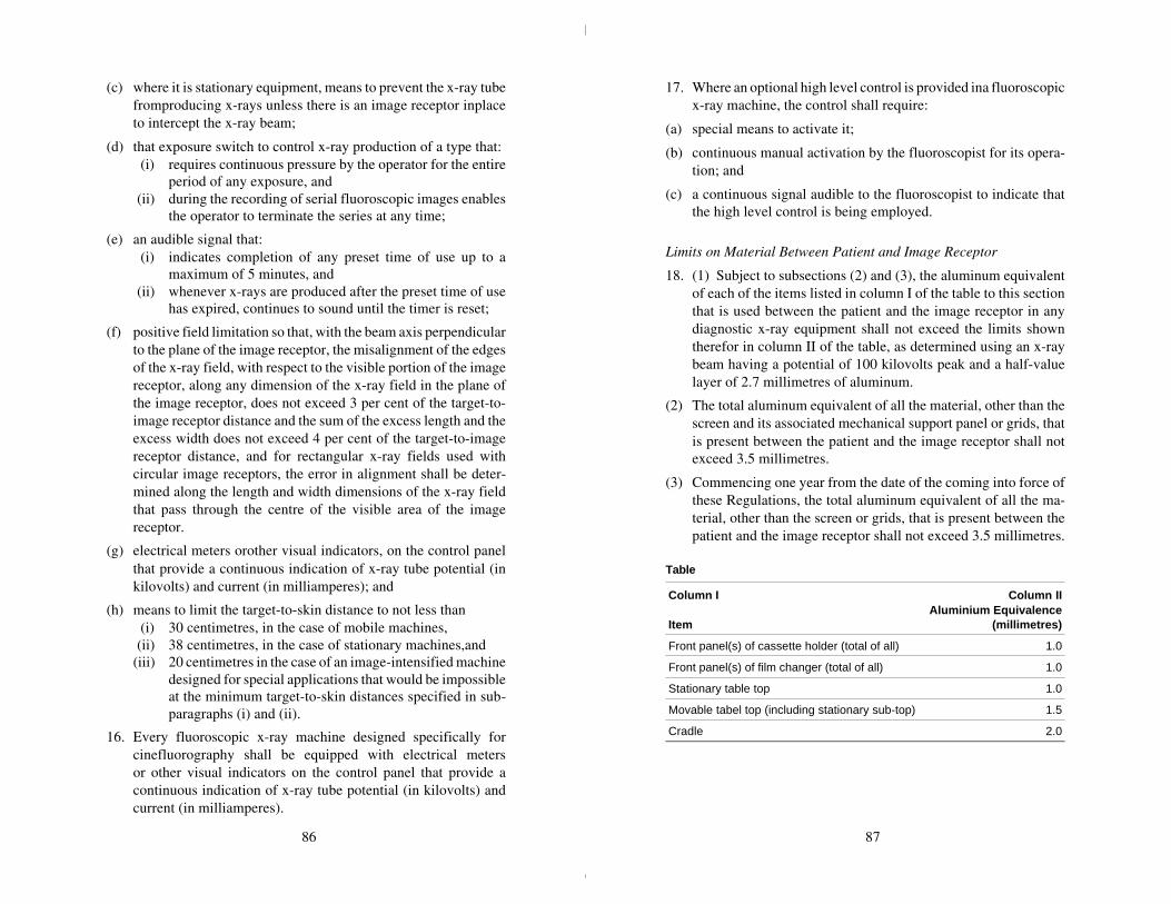
(c) where it is stationary equipment, means to prevent the x-ray tubefromproducing x-rays unless there is an image receptor inplaceto intercept the x-ray beam;
(d) that exposure switch to control x-ray production of a type that: (i) requires continuous pressure by the operator for the entire
period of any exposure, and (ii) during the recording of serial fluoroscopic images enables
the operator to terminate the series at any time;
(e) an audible signal that: (i) indicates completion of any preset time of use up to a
maximum of 5 minutes, and (ii) whenever x-rays are produced after the preset time of use
has expired, continues to sound until the timer is reset;
(f) positive field limitation so that, with the beam axis perpendicularto the plane of the image receptor, the misalignment of the edgesof the x-ray field, with respect to the visible portion of the imagereceptor, along any dimension of the x-ray field in the plane ofthe image receptor, does not exceed 3 per cent of the target-to-image receptor distance and the sum of the excess length and theexcess width does not exceed 4 per cent of the target-to-imagereceptor distance, and for rectangular x-ray fields used withcircular image receptors, the error in alignment shall be deter-mined along the length and width dimensions of the x-ray fieldthat pass through the centre of the visible area of the imagereceptor.
(g) electrical meters orother visual indicators, on the control panelthat provide a continuous indication of x-ray tube potential (inkilovolts) and current (in milliamperes); and
(h) means to limit the target-to-skin distance to not less than (i) 30 centimetres, in the case of mobile machines, (ii) 38 centimetres, in the case of stationary machines,and(iii) 20 centimetres in the case of an image-intensified machine
designed for special applications that would be impossibleat the minimum target-to-skin distances specified in sub-paragraphs (i) and (ii).
16. Every fluoroscopic x-ray machine designed specifically forcinefluorography shall be equipped with electrical metersor other visual indicators on the control panel that provide acontinuous indication of x-ray tube potential (in kilovolts) andcurrent (in milliamperes).
17. Where an optional high level control is provided ina fluoroscopicx-ray machine, the control shall require:
(a) special means to activate it;
(b) continuous manual activation by the fluoroscopist for its opera-tion; and
(c) a continuous signal audible to the fluoroscopist to indicate thatthe high level control is being employed.
Limits on Material Between Patient and Image Receptor
18. (1) Subject to subsections (2) and (3), the aluminum equivalentof each of the items listed in column I of the table to this sectionthat is used between the patient and the image receptor in anydiagnostic x-ray equipment shall not exceed the limits showntherefor in column II of the table, as determined using an x-raybeam having a potential of 100 kilovolts peak and a half-valuelayer of 2.7 millimetres of aluminum.
(2) The total aluminum equivalent of all the material, other than thescreen and its associated mechanical support panel or grids, thatis present between the patient and the image receptor shall notexceed 3.5 millimetres.
(3) Commencing one year from the date of the coming into force ofthese Regulations, the total aluminum equivalent of all the ma-terial, other than the screen or grids, that is present between thepatient and the image receptor shall not exceed 3.5 millimetres.
Table
Column I
Item
Column IIAluminium Equivalence
(millimetres)
Front panel(s) of cassette holder (total of all) 1.0
Front panel(s) of film changer (total of all) 1.0
Stationary table top 1.0
Movable tabel top (including stationary sub-top) 1.5
Cradle 2.0
86 87

Standards of Functioning
19. Every diagnostic x-ray machine when fully assembled for useshall function under normal conditions of use in such a mannerthat:
(a) for any given combination of x-ray tube potential (in kilovoltspeak), tube current (in milliamperes), exposure time (in seconds)of not less than 0.1 second, or for selected radiation exposure tothe image receptor (in milliroentgen) (i) the coefficient of variation of any ten consecutive radiation
exposure measurements, taken at the same source-to-detector distance within a time period of one hour, is nogreater than 0.05, and
(ii) each of the ten radiation exposures measured is within15 per cent of the mean value of the ten measurements,
when the line voltage for each measurement is within plus orminus 1 per cent of the mean value for all of the measurements,
(b) for any selected setting of the peak x-ray tube potential:(i) the actual peak kilovoltage corresponds to the selected
value to within plus or minus 5 per cent of the selectedvalue, and
(ii) for a line voltage variation of plus or minus 7 per cent ofits nominal value, the peak kilovoltage, prior to initiationof an exposure, is capable of being maintained to withinplus or minus 5 per cent of the selected value.
(c) the radiographic timer or automatic exposure control: (i) can be set to control irradiations as short as 1/60 second or
5 milliampere-seconds, whichever is greater; (ii) at each setting is accurate to 1/60 second or 7 per cent of
that setting, whichever is greater, and(iii) at each setting complies with the reproducibility require-
ments of paragraph (a);
(d) for any fixed indicated value of x-ray tube potential (in kilovoltspeak), within the range of values of operating tube potentialspecified for the equipment, the average ratios of exposure (inmilliroentgen) to the product of the tube current and exposuretime (in milliampere-seconds) obtained at any two consecutivetube current settings do not differ by more than 0.10 times theirsum, that is, to say
| X1 – X2 | £ 0.10 (X1 + X2);
where X1 and X2 are the average mR/mAs values obtained ateach of two consecutive tube current settings.
(e) the transmission of the primary x-ray beam through the mam-mographic image receptor support device referred to in para-graph 11(1)(b) results, with the equipment operated: (i) in the mammographic mode; (ii) at the minimum target-to-image receptor distance for
which it is designed, and(iii) at the maximum rated peak x-ray tube potential and maxi-
mum rated tube current-exposure time product for thatpeak tube potential,
in a radiation exposure, averaged over a detection area of100 square centimetres, with no linear dimension greater than20 centimetres and centred at 5 centimetres from any accessiblesurface beyond the plane of the support device, that does notexceed 0.1 milliroentgen for each activation of the x-ray tube;
(f) where it is a fluoroscopic x-ray machine (i) without automatic exposure rate control, at the shortest
target-to-skin distance specified for the equipment, nocombination of x-ray tube potential and current results inan entrance exposure rate, where the centre of the usefulbeam enters the patient, of greater than(A) 5 roentgen per minute except during recording of
fluoroscopic images, or(B) where an optional high level control is provided,
10 roentgen per minute with the high level controlactivated,
(ii) with automatic exposure rate control, at the shortest tar-get-to-skin distance specified for the equipment, no com-bination of x-ray tube potential and current results in anentrance exposure rate, where the centre of the useful beamenters the patient, of greater than(A) 10 roentgen per minute except during recording of
fluoroscopic images, or(B) where an optional high level control is provided,
5 roentgen per minute unless the high level control isactivated;
88 89

(g) subject to paragraph (h), the exposure rate fromleakage radiationaveraged over a detection area of 100 square centimetres with nolinear dimensions greater than 20 centimetres and located at adistance of 1 metre in any direction from the focal spot of thex-ray tube does not exceed 0.1 per cent of the exposure rate atthe same distance along the central axis of the useful beam;
(h) where it is a radiographic x-ray machine designed specificallyfor mammography, the exposure rate from leakage radiationaveraged over a detection area of 100 square centimetres with nolinear dimensions greater than 20 centimetres, located at 5 centi-metres from any point on the external surface of the x-ray tubehousing does not exceed 2 milliroentgen per hour;
(i) where there is a possibility of a high voltage appearing acrossthe x-ray tube without the exposure control or timer activated,the emission of x-radiation from the x-ray tube, with the beamlimiting device fully open, does not result in an exposure rate,averaged over a detection area of 100 square centimetres andcentred at 5 centimetres from any accessible external surface ofthe x-ray tube housing, in excess of 2 milliroentgen per hour;
(j) emission of ionizing radiation by any component other than thex-ray tube housing assembly, when the x-ray tube is operated atits maximum rated tube potential and current, does not result inan exposure rate averaged over a detection area of 100 squarecentimetres with no linear dimension greater than 20 centimetresand centred at 5 centimetres from any accessible surface of thecomponent, that exceeds 2 milliroentgen per hour, when aver-aged over a period of 1 hour; and
(k) when it is used for fluoroscopy, the exposure rate, averaged overa detection area of 100 square centimetres with no linear dimen-sion greater than 20 centimetres, of x-radiation due to transmis-sion of the useful beam through or scattering from the windowof the fluoroscopic imaging assembly, does not exceed 2 milli-roentgen per hour at 10 centimetres behind the plane of theimage receptor, for each roentgen per minute of entrance expo-sure rate.
Warning Sign Specifications
20. The x-radiation warning sign referred to in section 4 of this Partis a sign that:
(a) is shown in two contrasting colours;
(b) is clearly visible and identifiable from a distance of 1 metre;
(c) has no outer dimensions less than 2 centimetres;
(d) bears the words “CAUTION X-RAYS” and “ATTENTIONRAYONS X”; and
(e) is designed in accordance with the following diagram:
90 91
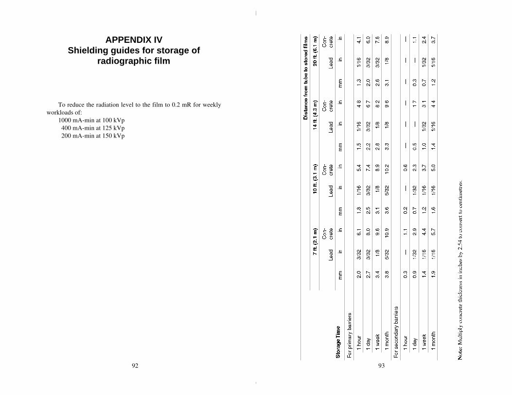
APPENDIX IVShielding guides for storage of
radiographic film
To reduce the radiation level to the film to 0.2 mR for weeklyworkloads of:
1000 mA-min at 100 kVp 400 mA-min at 125 kVp 200 mA-min at 150 kVp
92 93

APPENDIX VAgencies responsible for radiationsafety of medical x-ray installations
Alberta
DirectorRadiation Health BranchOccupational Health and Safety DivisionWorkers’ Health, Safety & Compensation2nd Floor, Oxbridge Place9820-106th StreetEdmonton, AlbertaT5K 2J6
British Columbia
Worker’s Compensation Board of British ColumbiaP.O. Box 5350 Stn TerminalVancouver, British ColumbiaV5Z 1E2
Manitoba
HeadPhysics DepartmentRadiation Protection SectionManitoba Cancer Treatment & Research Foundation700 Bannatyne AvenueWinnipeg, ManitobaR3E 0V9
New Brunswick
Senior Radiation PhysicistNew Brunswick Department of HealthP.O Box 6000Fredericton, New BrunswickE3B 5H1
Newfoundland
DirectorRadiation Protection OfficerDivision of Occupational Health and SafetyDepartment of Labour and ManpowerBeothuck Building, Crosbie PlaceSt. John’s, NewfoundlandA1C 5T7
Northwest Territories
ChiefHealth Programs and StandardsDepartment of HealthGovernment of the Northwest TerritoriesYellowknife, N.W.T.X1A 2N1
Nova Scotia
Radiation Health OfficerDepartment of Health7th Floor, Joseph Howe BuildingP.O. Box 488Halifax, Nova ScotiaB3J 2R8
Ontario
ChiefX-Ray Inspection ServiceOntario Ministry of Health7 Overlea Boulevard, 3rd FloorToronto, OntarioM4H 1A8
94 95

Prince Edward Island
ChairmanHospital Services Commission ofPrince Edward IslandP.O. Box 4500Charlottetown, P.E.I.C1A 7P4
Québec
Responsable de la radioprotectionService de l’agrément des laboratoires privésMinistère des affaires sociales1075, chemin Ste-FoyQuébec, QuébecG1S 2M1
Saskatchewan
Radiation Health OfficerOccupational Health and Safety DivisionDepartment of Labour1150 Rose StreetRegina, SaskatchewanS4R 1Z6
Yukon Territory
Director of Health ServicesGovernment of the Yukon TerritoryP.O. Box 2703Whitehorse, YukonY1A 2C6
APPENDIX VIRadiation measurement
units-international (SI) system
EXPOSUREThe COULOMB/KILOGRAM (C/kg) replaces the ROENTGEN (R)as the unit of exposure. The relationship between the two units is asfollows:
1 C/kg ~ 3876 R 1 R ~ 258 µ C/kg1 mC/kg ~ 3876 mR 1 mR ~ 258 nC/kg
(Note: m = milli = 10-3; µ = micro = 10-6; n = nano = 10-9)
ABSORBED DOSEThe GRAY (Gy) replaces the RAD (rad) as the unit of absorbed dose.The relationship between the two units is as follows:
1 Gy = 100 rad 1 rad = 10 mGy1 mGy = 100 mrad 1 mrad = 10 µGy
DOSE EQUIVALENTThe SIEVERT (Sv) replaces the REM (rem) as the unit of DOSEEQUIVALENT. The relationship between the two units is as follows:
1 Sv = 100 rem 1 rem = 10 mSv1 mSv = 100 mrem 1 mrem = 10 µSv
96 97
BibliographyFurther details on the topics covered in this Safety Code may be
obtained from the references listed below.
1. “Protection of the Patient in X-Ray Diagnosis”, ICRP Publica-tion 16, (1969).
2. “Recommendations of the International Commission on Radio-logical Protection”, ICRP Publication 26, Annals of the ICRP,Volume 1, No. 3, (1977).
3. “Structural Shielding Design and Evaluation For Medical Use ofX-Rays and Gamma Rays of Energies up to 10 MeV”, NationalCouncil on Radiation Protection and Measurements, NCRPReport No. 49, (1976).
4. “Medical Radiation Exposure of Pregnant and Potentially Preg-nant Women”, National Council on Radiation Protection andMeasurements, NCRP Report No. 54, (1977).
5. “The Effects on Populations of Exposure to Low Levels ofIonizing Radiation”, National Academy of Sciences, NationalResearch Council, Washington, D.C. (1972).
98


