30
X.25 TDC 364
| Date post: | 20-Dec-2015 |
| Category: |
Documents |
| View: | 227 times |
| Download: | 1 times |
X.25
TDC 364
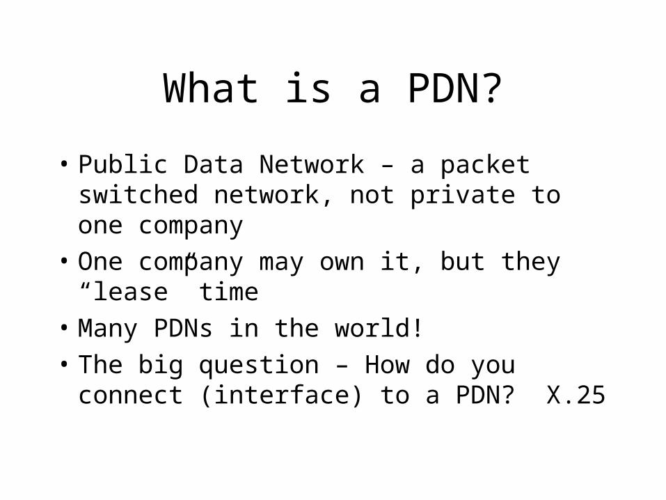
What is a PDN?
• Public Data Network – a packet switched network, not private to one company
• One company may own it, but they “lease” time
• Many PDNs in the world!
• The big question – How do you connect (interface) to a PDN? X.25

PDNs
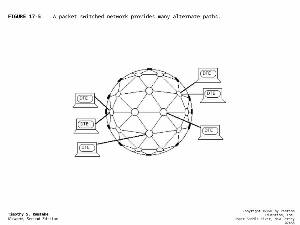
• Users connect at DTEs
• Network consists of DCEs (nodes) and communication links
• Always sets of redundant links
Timothy S. RamtekeNetworks, Second Edition
Copyright ©2001 by Pearson Education, Inc.Upper Saddle River, New Jersey 07458
All rights reserved.
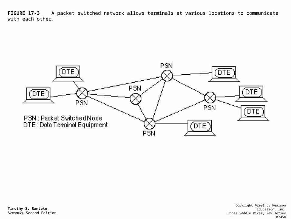
FIGURE 17-3 A packet switched network allows terminals at various locations to communicate with each other.
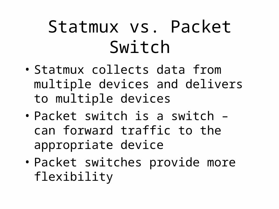
Statmux vs. Packet Switch
• Statmux collects data from multiple devices and delivers to multiple devices
• Packet switch is a switch – can forward traffic to the appropriate device
• Packet switches provide more flexibility

Timothy S. RamtekeNetworks, Second Edition
Copyright ©2001 by Pearson Education, Inc.Upper Saddle River, New Jersey 07458
All rights reserved.
FIGURE 17-4 (a) In this statistical multiplexing connection, x1 may only link up with y1. (b) In this packet switched connection, x1 may connect with any of the other terminals.
Timothy S. RamtekeNetworks, Second Edition
Copyright ©2001 by Pearson Education, Inc.Upper Saddle River, New Jersey 07458
All rights reserved.
FIGURE 17-5 A packet switched network provides many alternate paths.
X.25 is not alone
• X.25 is only one set of protocols
• X.25 is a three-layer protocol (physical, data link, and network/packet) similar but not exactly the same as the OSI model
• X.25 is the protocol that connects a DTE to a DCE, but only if the DTE is X.25 compatible

The PAD
• If the DTE is a un-intelligent terminal (non-X.25 compatible), then you need a PAD (packet assembler/disassembler)
• The non-compatible DTE connects first to the PAD (using X.28)
• The PAD follows the X.3 protocol
The PAD
• The PAD can be on the user premises. If so, then the PAD connects to the PDN via X.25
• The PAD could also be provided by the network provider and reside at the PDN.
Timothy S. RamtekeNetworks, Second Edition
Copyright ©2001 by Pearson Education, Inc.Upper Saddle River, New Jersey 07458
All rights reserved.
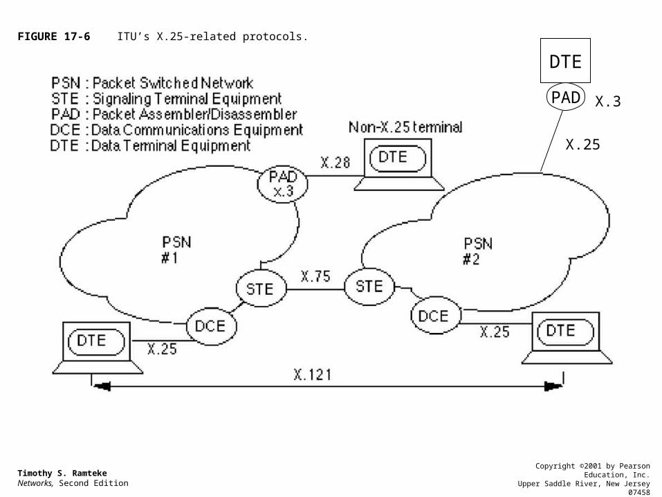
FIGURE 17-6 ITU’s X.25-related protocols.
DTE
PAD X.3
X.25
Other Protocols
• X.75 – The protocol that interconnects multiple PDNs
• X.121 – The protocol that provides the proper way of addressing networks via country codes, network codes, and terminal numbers
The Physical Layer of X.25
• The physical layer of X.25 is defined by X.21
• Since X.21 is rarely used, most installations use EIA-232 or V.35 or V.24/V.28 standard
The Data Link Layer
• ITU-T recommends the LAP-B protocol for the data link layer
• Recall: LAP-B is similar to HDLC or SDLC• Thus, LAP-B defines 3 types of frames:
– Information– Supervisory– Unnumbered
Three Modes of Data LinkLayer Operation
• SNRM (Set Normal Response Mode) – a multipoint protocol is used to perform polling and selecting
• SARM (Set Asynchronous Response Mode) – used for half-duplex point-to-point connections
• SABM (Set Asynchronous Balanced Mode) – Full-duplex and point-to-point connection

Other Data LinkLayer Frames
• DTEs and DCEs may also issue:– UA (Unnumbered Acknowledgement)– DISC (Disconnect)– FRMR (Frame reject)– RR (Receive ready)– DM (Disconnect mode)

Timothy S. RamtekeNetworks, Second Edition
Copyright ©2001 by Pearson Education, Inc.Upper Saddle River, New Jersey 07458
All rights reserved.
FIGURE 17-7 Exchange of frames over a DTE-DCE link.
The X.25 Network Layer
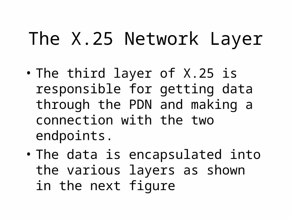
• The third layer of X.25 is responsible for getting data through the PDN and making a connection with the two endpoints.
• The data is encapsulated into the various layers as shown in the next figure

Timothy S. RamtekeNetworks, Second Edition
Copyright ©2001 by Pearson Education, Inc.Upper Saddle River, New Jersey 07458
All rights reserved.
FIGURE 17-8 The three layers of X.25.
Four Types ofNetwork Connections
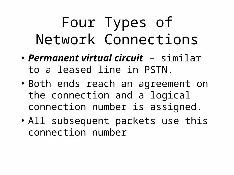
• Permanent virtual circuit – similar to a leased line in PSTN.
• Both ends reach an agreement on the connection and a logical connection number is assigned.
• All subsequent packets use this connection number

Four Types ofNetwork Connections
• Virtual call – similar to a POTS connection• First side issues a call request. If accepted,
a call accept packet is returned.• A logical connection number is assigned
and all subsequent packets use this ID• When call is complete, a clear request is
issued• Temporary connection

Four Types ofNetwork Connections
• Fast select – allows one DTE to transfer data to another DTE without the call establishment and termination procedures
• When a fast select is issued, up to 128 bytes of data may accompany the command
• Receiver may respond with clear request, which means I accept your data, thanks, see you later

Four Types ofNetwork Connections
• Receiver may also respond with call accepted, which means I accept your data and let’s establish a connection for further data transfers
• In both cases, receiver may also attach 128 bytes of immediate data

Four Types ofNetwork Connections
• Fast select with immediate clear – same as fast select but receiver has only one choice when it receives data – thanks for the data and see you later
Network Layer Packet Format
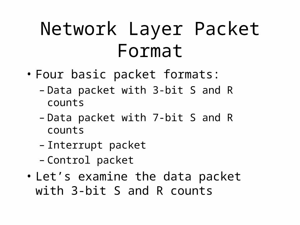
• Four basic packet formats:– Data packet with 3-bit S and R counts– Data packet with 7-bit S and R counts– Interrupt packet– Control packet
• Let’s examine the data packet with 3-bit S and R counts

Timothy S. RamtekeNetworks, Second Edition
Copyright ©2001 by Pearson Education, Inc.Upper Saddle River, New Jersey 07458
All rights reserved.
FIGURE 17-11 The three-octet packet header.

Network Layer Packet
• Note that you can have up to 12 bits for a logical channel identifier– 4-bit logical group number– 8-bit logical channel number
• This gives 4095 possible connections between a DTE and a DCE (channel 0 is reserved for network diagnostics)

Timothy S. RamtekeNetworks, Second Edition
Copyright ©2001 by Pearson Education, Inc.Upper Saddle River, New Jersey 07458
All rights reserved.
FIGURE 17-12 Local vs. end-end acknowledgements.

Timothy S. RamtekeNetworks, Second Edition
Copyright ©2001 by Pearson Education, Inc.Upper Saddle River, New Jersey 07458
All rights reserved.
FIGURE 17-13 Establishing a connection using the 3 layers of X.25.

Timothy S. RamtekeNetworks, Second Edition
Copyright ©2001 by Pearson Education, Inc.Upper Saddle River, New Jersey 07458
All rights reserved.
FIGURE 17-17 (a) A typical BSC network. (b) Implementing a BSC network over a packet switched network introduces many new benefits.


![Power-Delivery Network in 3D ICs: Monolithic 3D vs. Skybridge 3D … · 2017. 9. 9. · Cadence Voltus [11] based circuit-level PDN evaluation. The S3DC’s PDN design is compared](https://static.documents.pub/doc/80x56/60e76bfe3332f155df771da8/power-delivery-network-in-3d-ics-monolithic-3d-vs-skybridge-3d-2017-9-9-cadence.jpg)


