18
1 www.amcelettronica.com X64GP series v.1.0 X64 GP HYBRID ALARM CONTROL UNIT USER MANUAL EN 50131-1 EN 50131-3 EN 50131-6 EN 50136-1 EN 50136-2 CLASS II

1 www.amcelettronica.com X64GP series v.1.0
X64 GP HYBRID ALARM CONTROL UNIT
USER MANUAL
EN 50131-1EN 50131-3EN 50131-6EN 50136-1EN 50136-2CLASS II
2 www.amcelettronica.com X64GP series v.1.0
IMPORTANT NOTES• The following manual has been prepared to provide assistance to users who use the system. All those who
use the systems listed in this manual must be authorized.• The information contained in this document are property of AMC Elettronica s.r.l. • All information contained in this document is subject to change without notice.• Every part of this manual should be interpreted and used only for the purposes for which it was drafted, the
use other than as prescribed must be authorized by AMC Elettronica srl, under penalty of forfeiture of the guarantee.
• All trademarks, symbols and examples contained in this manual belong to their respective owners.
GUARANTEEAMC Electronics s.r.l. ensures that products are free from defects in workmanship. The product is not installed by the manufacturer and can be used with other products not manufactured by AMC Elettronica srl, the manufacturer does not guarantee or be held responsible for damage and / or theft or other types of issues caused by an incorrect installation and / or configuration of the system.Is not guaranteed to:
- improper use of the panel- programming errors- manipulation and vandalism- wear and tear- lightning, floods, fire.AMC Electronics s.r.l. reserves the right to repair or replace the defective product within the limits established for 24 months.A different use from that stated in this manual will void the warranty. The installation must be performed in a workmanlike manner by qualified personnel.
COMPLIANCEAMC Electronics s.r.l. declares that the X alarm control unit is provision of Directive 1999/5 /CEOn our web site www.amcelettronica.comSTANDARDS:EN 50136-1 + EN 50136-2 ( GSM and PSTN alarm transmission) All products mentioned in this manual are in accordance with the rules:EN 50131-1 + EN 50131-3 + EN 50131-6 (control and indicating equioment for alarm system)EN 50136-1 + EN 50136-2 ( GSM and PSTN alarm transmission) Following is the list of normed products:X64GPUNIKA: keypadKLCD: keypadKLight: keypadKLight plus: keypad with 2 in/out terminalKXIN: inputs expansionKXOUT: outputsTransformer 25VATransformer 30VA Xgprs/gsm: gsm - gprs module IP1: IP module

3 www.amcelettronica.com X64GP series v.1.0
AMC Elettronica s.r.l.Via Pascoli 35922040 Alzate BrianzaComoItalyTel. +39031632780Fax [email protected]
MANUFATURER
CONTENT OF THE PLASTIC & METAL BOXIn the carton box there is:
- Metal or plastic box with inside: - Panel board - Tranformer - Earth cable - housing fuse - Balancing resistors (8 of 1K - 8 of 2K2) - plastic bag with screws and plastic turrets for fix all parts and close the box - Adesive data label - user manual
The packaging does not contain:- kit Tamper for antiopening and removal (mandatory for EN approval)- Installation Manual- backup battery- programming Software InstallDBExplorer- fisher for fix on the wall the palstic box
The material not included in the box can be purchased except: the programming software and Installation manual can be downloaded from our site: www.amcelettronica.com
4 www.amcelettronica.com X64GP series v.1.0
INTRODUCTION X64GP series are Hybrid security control panel for building protection conform to: EN 50131-1 + EN 50131-3 + EN 50131-6 (control and indicating equiment for alarm system) + EN 50136-1 + EN 50136-2 2013 (GPRS - GSM alarm transmission) The control panel are equipped of 8 zones, expandable to 64 with remote modules, for wired zones.It is possible program 56 wireless devices (20 keyfobs - 32 devices - 4 wireless sirens) without expnasion, only by using the internal wireless receiver. It is possible add anothe remote receiver (expr800 - Kradio) for dub the number of wireless devices.
ALARM COMUNICATION X64GP series are able to notify one or more situations of ALARM, ROBBERY, TAMPERING AN TROUBLE with different carriers:- GSM/GPRS optional module type ATS3/SP3 refered to EN 50136-2:2013 **The programmming can be via local keypad or a PC with specific software.
* after specific programming and by enable the automatic EN configurator in panel (see description below)** to ensure the classification SP3 the periodic test call must be programmed for work every 30’ minutes, or for have classification SP2, the periodic test call can be programmed for work every 25h.See the table with option below
NOTIFICATION EQUIPMENT DESCRIPTION AND CONFIGUARATION
Option A program 2 outs internal siren + SP2 comunication device (GSM/GPRS)
Option B Autopowered Siren + SP2 comunication device (GSM/GPRS)
Option D SP3 comunication device (GSM/GPRS) with life test call every 30’
The notifications of alarm, robbery, intrusion, fault, manipultion, and other conditions must be signaled by ATS and Siren, in accor-dance with the requirements specified in Tables to ensure the certification EN 50131-1:2013 and the grade certified.
LEVELS OF ACCESSThe standard EN 50131 defines the following access levels:
Level 1: access by any person (no code require)Level 2: User Access by code. Level 2 is the access of person that will use the system like ARM/DISARM and all operation that the rules of EN 50131 approval permitted. This level allows the entry of the code level 3 (installer)Level 3: Intsaller. This level is the person or gorup of persons that will program all function of panel according with rules of EN approval and in according with specific needs of Final user LEVEL 2. Another important function of Level 3 is teach to the user level 2 how to use the system when is already programmed.Level 4: this is the manufactorer level, this access allow to modify the internal function of system. This level has the obligation to build and design the system following the current standards.
EVENT STORAGE SYSTEMThe system has a memory for storage all events produced from panel, the number of these events is 1000, when the system will arrive at the end of the number of events storable, will proceed to delete the old one of the1000 registered.All events are stored in EEPROM components, and therefore not erasable and remain always stored, also in case of absence of main power.The delete of events can be made only by the manufacturer.
DEVICES FOR CONTROL OF THE SYSTEMThere are 2 type of device for control of panel:Type A: Klcd and KlightType B: Klight plusType C: Unika touch screen kpadsee the explanation in this manual

5 www.amcelettronica.com X64GP series v.1.0
SPECIFICATIONS X64zones 8 -64 wired
wireless zones 64 zones
outputs 2 on board - espandible to 14 (with 4 expansion)
user code/tag/remote
64 users
partitions 8
group 4
keypad 8
tag reader 8
event memory 1000
phone numbers 8 for SMS + 8 for protocols
carriers GSM/GPRS
other inputs TAMPER line / mechanical antiopening tamper
PC software yes
remote managementGPRS
apps (Apple - Android)
timers 8 per day week
The main features are:
6 www.amcelettronica.com X64GP series v.1.0
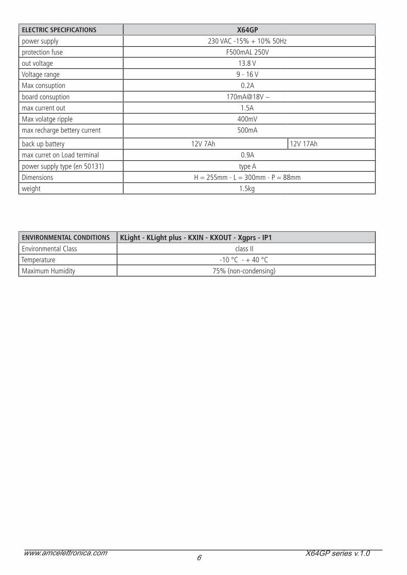
ELECTRIC SPECIFICATIONS X64GPpower supply 230 VAC -15% + 10% 50Hz
protection fuse F500mAL 250V
out voltage 13.8 V
Voltage range 9 - 16 V
Max consuption 0.2A
board consuption 170mA@18V ~
max current out 1.5A
Max volatge ripple 400mV
max recharge bettery current 500mA
back up battery 12V 7Ah 12V 17Ah
max curret on Load terminal 0.9A
power supply type (en 50131) type A
Dimensions H = 255mm - L = 300mm - P = 88mm
weight 1.5kg
ENVIRONMENTAL CONDITIONS KLight - KLight plus - KXIN - KXOUT - Xgprs - IP1Environmental Class class II
Temperature -10 °C - + 40 °C
Maximum Humidity 75% (non-condensing)
7 www.amcelettronica.com X64GP series v.1.0
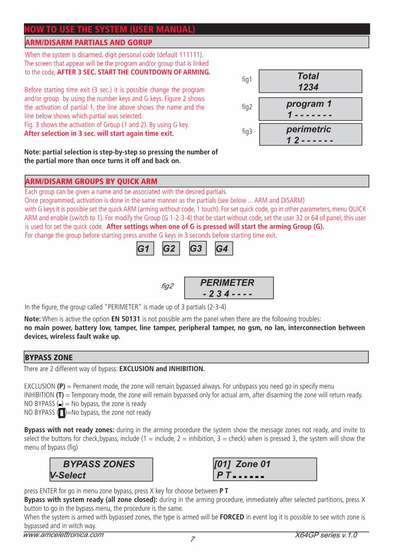
HOW TO USE THE SYSTEM (USER MANUAL)ARM/DISARM PARTIALS AND GORUP
When the system is disarmed, digit personal code (default 111111).The screen that appear will be the program and/or group that is linked to the code, AFTER 3 SEC. START THE COUNTDOWN OF ARMING.
Before starting time exit (3 sec.) it is possible change the program and/or group by using the number keys and G keys. Figure 2 shows the activation of partial 1, the line above shows the name and the line below shows which partial was selected. Fig. 3 shows the activation of Group (1 and 2). By using G key.After selection in 3 sec. will start again time exit.
Total1234
fig1
fig3
fig2
Note: partial selection is step-by-step so pressing the number of the partial more than once turns it off and back on.
ARM/DISARM GROUPS BY QUICK ARMEach group can be given a name and be associated with the desired partials.Once programmed, activation is done in the same manner as the partials (see below ... ARM and DISARM)with G keys it is possible set the quick ARM (arming without code, 1 touch). For set quick code, go in other parameters, menu QUICK ARM and enable (switch to 1). For modify the Group (G 1-2-3-4) that be start without code, set the user 32 or 64 of panel, this user is used for set the quick code. After settings when one of G is pressed will start the arming Group (G). For change the group before starting press anothe G keys in 3 seconds before starting time exit.
G1 G2 G4G3
fig2
In the figure, the group called "PERIMETER" is made up of 3 partials (2-3-4)
program 11 - - - - - - -perimetric1 2 - - - - - -
PERIMETER- 2 3 4 - - - -
There are 2 different way of bypass: EXCLUSION and INHIBITION.
EXCLUSION (P) = Permanent mode, the zone will remain bypassed always. For unbypass you need go in specify menuINHIBITION (T) = Temporary mode, the zone will remain bypassed only for actual arm, after disarming the zone will return ready.NO BYPASS ( ) = No bypass, the zone is readyNO BYPASS ( )=No bypass, the zone not ready
Bypass with not ready zones: during in the arming procedure the system show the message zones not ready, and invite to select the buttons for check,bypass, include (1 = include, 2 = inhibition, 3 = check) when is pressed 3, the system will show the menu of bypass (fig)
press ENTER for go in menu zone bypass, press X key for choose between P TBypass with system ready (all zone closed): during in the arming procedure, immediately after selected partitions, press X button to go in the bypass menu, the procedure is the same.When the system is armed with bypassed zones, the type is armed will be FORCED in event log it is possible to see witch zone is bypassed and in witch way.
BYPASS ZONE
BYPASS ZONESV-Select
[01] Zone 01 P T
Note: When is active the option EN 50131 is not possible arm the panel when there are the following troubles:no main power, battery low, tamper, line tamper, peripheral tamper, no gsm, no lan, interconnection between devices, wireless fault wake up.
8 www.amcelettronica.com X64GP series v.1.0
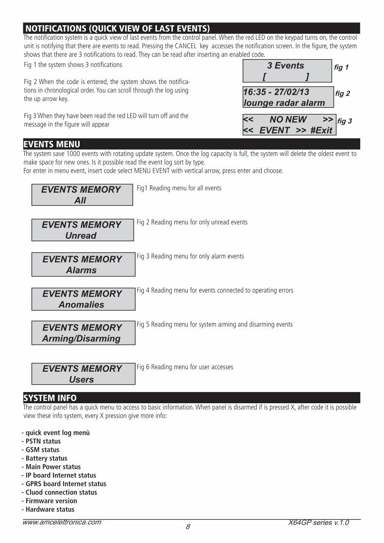
The notification system is a quick view of last events from the control panel. When the red LED on the keypad turns on, the control unit is notifying that there are events to read. Pressing the CANCEL key accesses the notification screen. In the figure, the system shows that there are 3 notifications to read. They can be read after inserting an enabled code.Fig 1 the system shows 3 notifications
Fig 2 When the code is entered, the system shows the notifica-tions in chronological order. You can scroll through the log using the up arrow key.
Fig 3 When they have been read the red LED will turn off and the message in the figure will appear
fig 2
fig 1
NOTIFICATIONS (QUICK VIEW OF LAST EVENTS)
3 Events[ ]
16:35 - 27/02/13lounge radar alarm
<< NO NEW >><< EVENT >> #Exit
fig 3
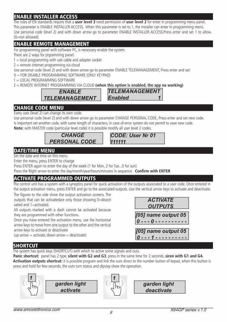
EVENTS MENUThe system save 1000 events with rotating update system. Once the log capacity is full, the system will delete the oldest event to make space for new ones. Is it possible read the event log sort by type.For enter in menu event, insert code select MENU EVENT with vertical arrow, press enter and choose.
Fig1 Reading menu for all events
Fig 2 Reading menu for only unread events
Fig 3 Reading menu for only alarm events
Fig 4 Reading menu for events connected to operating errors
Fig 5 Reading menu for system arming and disarming events
Fig 6 Reading menu for user accesses
EVENTS MEMORYAll
EVENTS MEMORYUnread
EVENTS MEMORYAlarms
EVENTS MEMORYAnomalies
EVENTS MEMORYArming/Disarming
EVENTS MEMORYUsers
SYSTEM INFOThe control panel has a quick menu to access to basic information. When panel is disarmed if is pressed X, after code it is possible view these info system, every X pression give more info:
- quick event log menù- PSTN status- GSM status- Battery status- Main Power status- IP board Internet status- GPRS board Internet status- Cluod connection status- Firmware version- Hardware status
9 www.amcelettronica.com X64GP series v.1.0
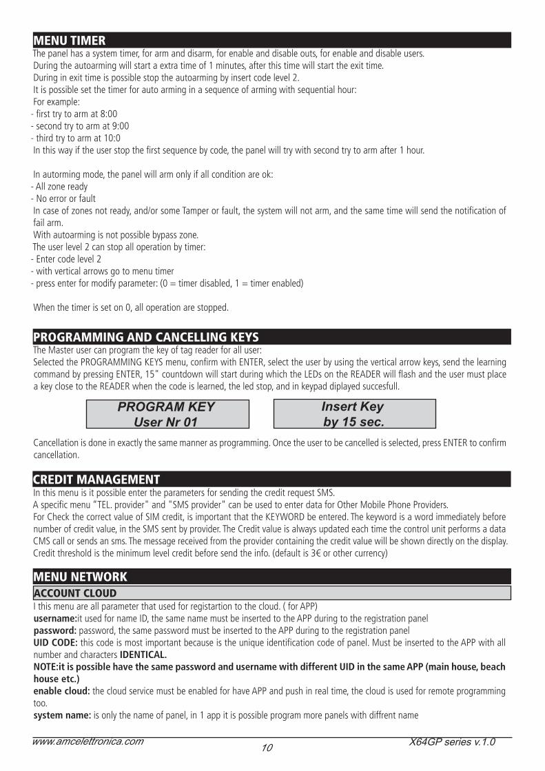
ENABLE INSTALLER ACCESSThe rules of EN standards require that a user level 3 need permission of user level 2 for enter in programming menu panel.This parameter is ENABLE INSTALLER ACCESS. When this parameter is set to 1, the installer can enter in programming menù. Use personal code (level 2) and with down arrow go to parameter ENABLE INSTALLER ACCESS,Press enter and set 1 to allow. (0=not allowed)
ENABLE REMOTE MANAGEMENTFor programming panel with software PC, is necessary enable the system.There are 2 ways for prgramming panel:1 = local programming with usb cable and adapter socket2 = remote internet programming via cloudUse personal code (level 2) and with down arrow go to parameter ENABLE TELEMANAGEMENT, Press enter and set:0 = FOR DISABLE PROGRAMMING SOFTWARE (ONLY KEYPAD)1 = LOCAL PROGRAMMING SOFTWARE2 = REMOTE INTERNET PROGRAMMING VIA CLOUD (when this option is enabled, the app no working)
ENABLETELEMANAGEMENT
TELEMANAGEMENTEnabled 1
CHANGE CODE MENUEvery user (level 2) can change its own code.Use personal code (level 2) and with down arrow go to parameter CHANGE PERSONAL CODE, Press enter and set new code.Is important set another code, with same length of characters, in case of error system do not permit to save new code.Note: with MASTER code (particular level code) it is possible modify all user level 2 codes.
CHANGEPERSONAL CODE
CODE: User Nr 01111111
DATE/TIME MENUSet the date and time on this menuEnter the menu, press ENTER to changePress ENTER again to enter the day of the week (1 for Mon, 2 for Tue...0 for sun)Press the Right arrow to enter the day/month/year/hours/minutes in sequence Confirm with ENTER
ACTIVATE PROGRAMMED OUTPUTSThe control unit has a system with a synoptics panel for quick activation of the outputs associated to a user code. Once entered in the output activation menu, press ENTER and go to the associated outputs. Use the vertical arrow keys to activate and deactivate.The figures to the side show the output activation screens. The outputs that can be activatedare only those showing 0=deacti-vated and 1=activated.All outputs marked with a dash cannot be activated because they are programmed with other functions.Once you have entered the activation menu, use the horizontal arrow keys to move from one output to the other and the vertical arrow keys to activate or deactivate (up arrow = activate, down arrow = deactivate)
ACTIVATEOUTPUTS
[05] name output 050 - - - 0 - - - - - - - - - -
[05] name output 050 - - - 1 - - - - - - - - - -
SHORTCUTThe system has quick keys (SHORTCUT) with which to active some signals and outs.Panic shortcut: panel has 2 type, silent with G2 and G3, press in the same time for 2 seconds, siren with G1 and G4. Activation outputs shortcut: it is possible program and link the outs direct to the number button of kepad, when this button is press and hold for few seconds, the outs turn status and dipslay show the operation.
garden lightactivate
1 1garden lightdeactivate
10 www.amcelettronica.com X64GP series v.1.0
MENU TIMERThe panel has a system timer, for arm and disarm, for enable and disable outs, for enable and disable users.During the autoarming will start a extra time of 1 minutes, after this time will start the exit time.During in exit time is possible stop the autoarming by insert code level 2.It is possible set the timer for auto arming in a sequence of arming with sequential hour:For example:
- first try to arm at 8:00- second try to arm at 9:00- third try to arm at 10:0In this way if the user stop the first sequence by code, the panel will try with second try to arm after 1 hour.
In autorming mode, the panel will arm only if all condition are ok:- All zone ready- No error or faultIn case of zones not ready, and/or some Tamper or fault, the system will not arm, and the same time will send the notification of fail arm.With autoarming is not possible bypass zone.The user level 2 can stop all operation by timer:- Enter code level 2- with vertical arrows go to menu timer- press enter for modify parameter: (0 = timer disabled, 1 = timer enabled)
When the timer is set on 0, all operation are stopped.
PROGRAMMING AND CANCELLING KEYSThe Master user can program the key of tag reader for all user:Selected the PROGRAMMING KEYS menu, confirm with ENTER, select the user by using the vertical arrow keys, send the learning command by pressing ENTER, 15" countdown will start during which the LEDs on the READER will flash and the user must place a key close to the READER when the code is learned, the led stop, and in keypad diplayed succesfull.
Cancellation is done in exactly the same manner as programming. Once the user to be cancelled is selected, press ENTER to confirm cancellation.
CREDIT MANAGEMENTIn this menu is it possible enter the parameters for sending the credit request SMS.A specific menu “TEL. provider" and "SMS provider" can be used to enter data for Other Mobile Phone Providers.For Check the correct value of SIM credit, is important that the KEYWORD be entered. The keyword is a word immediately before number of credit value, in the SMS sent by provider. The Credit value is always updated each time the control unit performs a data CMS call or sends an sms. The message received from the provider containing the credit value will be shown directly on the display.Credit threshold is the minimum level credit before send the info. (default is 3€ or other currency)
PROGRAM KEYUser Nr 01
Insert Keyby 15 sec.
MENU NETWORKACCOUNT CLOUDI this menu are all parameter that used for registartion to the cloud. ( for APP)username:it used for name ID, the same name must be inserted to the APP during to the registration panelpassword: password, the same password must be inserted to the APP during to the registration panelUID CODE: this code is most important because is the unique identification code of panel. Must be inserted to the APP with all number and characters IDENTICAL.NOTE:it is possible have the same password and username with different UID in the same APP (main house, beach house etc.)enable cloud: the cloud service must be enabled for have APP and push in real time, the cloud is used for remote programming too.system name: is only the name of panel, in 1 app it is possible program more panels with diffrent name
11 www.amcelettronica.com X64GP series v.1.0
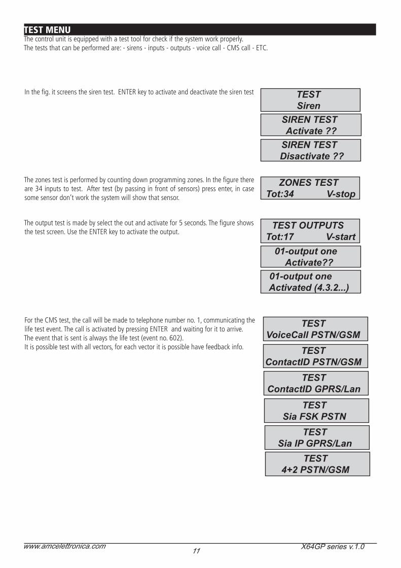
TEST MENUThe control unit is equipped with a test tool for check if the system work properly.The tests that can be performed are: - sirens - inputs - outputs - voice call - CMS call - ETC.
TESTSiren
SIREN TEST Activate ??
SIREN TEST Disactivate ??
ZONES TEST Tot:34 V-stop
TEST OUTPUTS Tot:17 V-start 01-output one
Activate?? 01-output one
Activated (4.3.2...)
TESTContactID PSTN/GSM
In the fig. it screens the siren test. ENTER key to activate and deactivate the siren test
TESTVoiceCall PSTN/GSM
TESTContactID GPRS/Lan
TESTSia FSK PSTN
TESTSia IP GPRS/Lan
TEST4+2 PSTN/GSM
The zones test is performed by counting down programming zones. In the figure there are 34 inputs to test. After test (by passing in front of sensors) press enter, in case some sensor don’t work the system will show that sensor.
The output test is made by select the out and activate for 5 seconds. The figure shows the test screen. Use the ENTER key to activate the output.
For the CMS test, the call will be made to telephone number no. 1, communicating the life test event. The call is activated by pressing ENTER and waiting for it to arrive.The event that is sent is always the life test (event no. 602).It is possible test with all vectors, for each vector it is possible have feedback info.

12 www.amcelettronica.com X64GP series v.1.0
ARM/DISARM THE CONTROL UNIT VIA SMSTo arm and/or disarm the control unit you must have a user code: UPWD:111111 ARM=T TOTAL ARMING UPWD:111111 ARM=1 PARTIAL1 ARMING UPWD:111111 ARM=123 ARMING OF PARTIALS 1 - 2 - 3 UPWD:111111 DISARM=T TOTAL DISARMING UPWD:111111 DISARM= 2 DISARMING OF ONLY PARTIAL 2 UPWD:111111 DISARM= 12 DISARMING OF PARTIALS 1 - 2 UPWD:111111 ARM? ARMING STATUS REQUEST FROM THE CONTROL UNIT ARM = 0 DISARMED ARM =T TOTAL ARMED ARM = 12 PARTIALS 1 - 2 ARMED
This is the complete list of all of the system programming/querying commands
LOCK SYSTEM UNLOCK COMMAND (to allow to modify phone numbers) (LOCK=1 for unlock)TPWD TECHNICIAN PASSWORD DECLARATION (TPWD:000000 CODE)UPWD USER PASSWORD DECLARATION (UPWD:111111 CODE)ARM ARMING COMMAND (T=total 1=partial 1 etc.)DISARM DISARMING COMMAND (OUT.x OUTPUT SELECTION COMMANDIN.x INPUT SELECTION COMMANDTEL.x TELEPHONE SELECTION COMMAND: IS USED FOR USER/INSTALLER CODE= COMMAND FOR ASSIGN PARAMETER? REQUEST INFO COMMAD
SMS COMMANDS
SMS MANAGEMENT
UPWD:111111 ARM=T TOTAL ARMING
Without spaces One space Without spaces
To send a command to the system you need follow a few simple rules:For example, in order to the installer to change a telephone number, he must first have authorisation from the system owner (system unlock)UPWD:111111 LOCK=OFF this command unlocks the programming via sms for 20 minutes. This unlock must be done by the system owner. (final user)Now the installer can give the command:As you can see, the message is made up of two commands: TPWD:000000 TEL.1=+393358554574
1 - the password declaration (TPWD:000000 or UPWD:111111) This command requires the (: ) (colon) to enter the code.2 - this is the operational part of the message that uses the (=) to assign the operation, the (?) to request information (a few examples follow)
TEL.1=+393358554574 setting telephone number response from the system TEL.1:OKOUT.2=onoutput 2 activation response from the system OUT.:OKOUT.4=off deactivation of output 4 response from the system OUT.4:OKIN.2? input 2 status request response from the system IN.2=OP (if open) IN.2=CL (if at rest)
HOW TO CREATE A REQUEST AND PROGRAMMING SMS
Without spaces One space Without spaces
13 www.amcelettronica.com X64GP series v.1.0
AMC AMANAGER APPAMC MANAGER is an application for smrtphone that allow the user to manage many parameters of panel:
- arm and disarm all partitions of panel- bypass all programmed zones- turn ON and OFF all programmed output- monitoring system status - back up battery - main power - all type of Tamper - gsm signal - PSTN line status - peripheral status - connection cables - wireless trouble- Log events
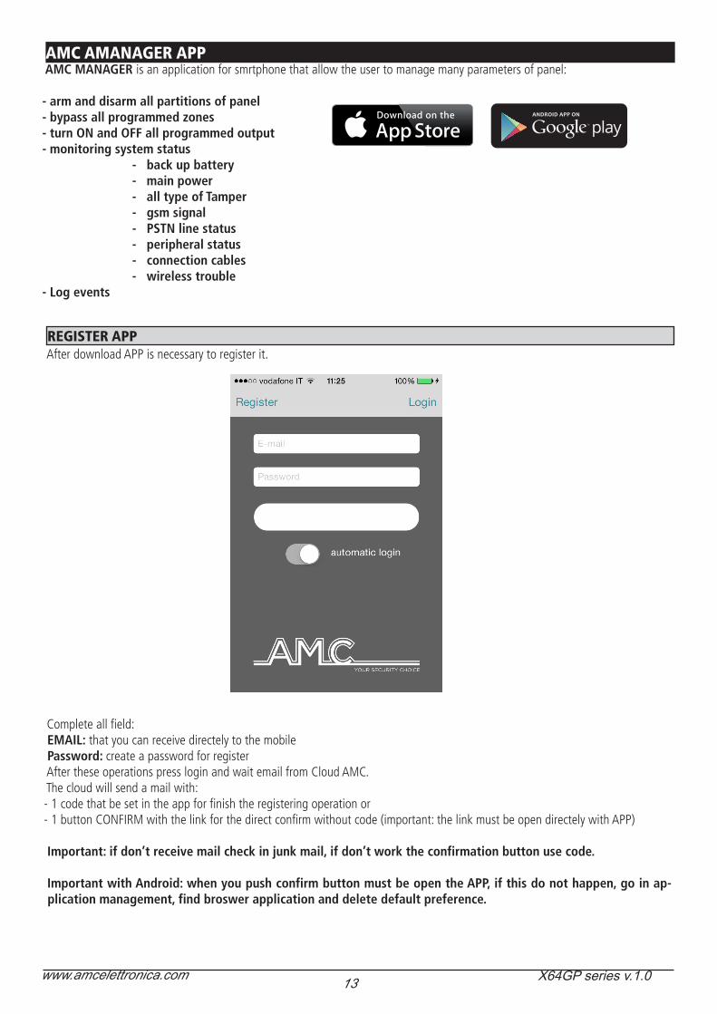
REGISTER APPAfter download APP is necessary to register it.
Complete all field: EMAIL: that you can receive directely to the mobilePassword: create a password for registerAfter these operations press login and wait email from Cloud AMC.The cloud will send a mail with:- 1 code that be set in the app for finish the registering operation or - 1 button CONFIRM with the link for the direct confirm without code (important: the link must be open directely with APP)
Important: if don’t receive mail check in junk mail, if don’t work the confirmation button use code.
Important with Android: when you push confirm button must be open the APP, if this do not happen, go in ap-plication management, find broswer application and delete default preference.
14 www.amcelettronica.com X64GP series v.1.0
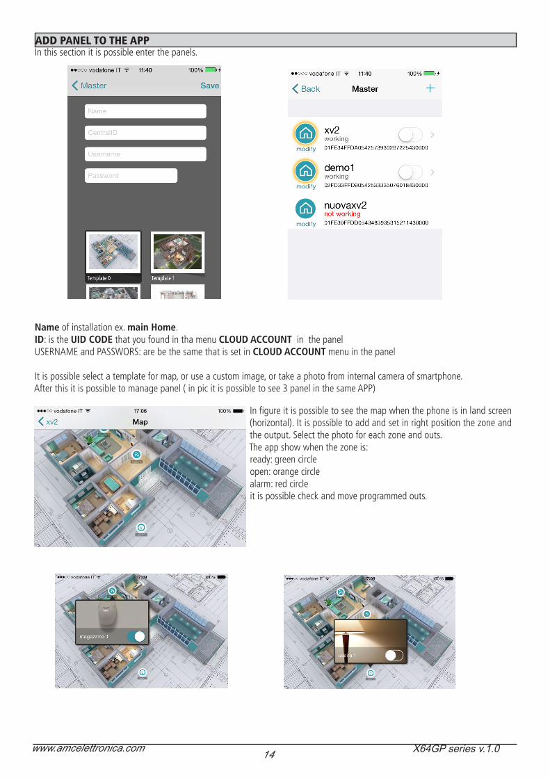
ADD PANEL TO THE APPIn this section it is possible enter the panels.
Name of installation ex. main Home.ID: is the UID CODE that you found in tha menu CLOUD ACCOUNT in the panelUSERNAME and PASSWORS: are be the same that is set in CLOUD ACCOUNT menu in the panel
It is possible select a template for map, or use a custom image, or take a photo from internal camera of smartphone.After this it is possible to manage panel ( in pic it is possible to see 3 panel in the same APP)
In figure it is possible to see the map when the phone is in land screen (horizontal). It is possible to add and set in right position the zone and the output. Select the photo for each zone and outs.The app show when the zone is:ready: green circleopen: orange circlealarm: red circleit is possible check and move programmed outs.
15 www.amcelettronica.com X64GP series v.1.0
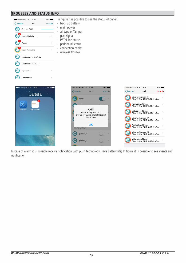
TROUBLES AND STATUS INFO
In figure it is possible to see the status of panel:- back up battery- main power- all type of Tamper- gsm signal- PSTN line status- peripheral status- connection cables- wireless trouble
In case of alarm it is possible receive notification with push technology (save battery life) In figure it is possible to see events and notification.

16 www.amcelettronica.com X64GP series v.1.0
USER KEYPAD MENU - 1
USER CODE111111
0=TOT 1-8=PRG12_45_78
Arming start automatically after 3seconds
1 2
987
6
3
54
0
MENUEVENTS
EVENTS MEMORYAll
EVENTS MEMORYUnread
EVENTS MEMORYAlarms
EVENTS MEMORYAnomalies
EVENTS MEMORYArming/Disarming
EVENTS MEMORYUsers
ACTIVATEOUTPUTS
[01] output one0 1 0 0 - - - - - - - - - -
sx dx
up
down
Keys sx and dx for outputs selection
Keys up and down for activate and deactivate
- = Not programmed0 = Deactivate1 = Activate
ENABLETELEMANAGEMENT
TELEMANAGEMENTEnabled 0
ENABLE INSTALLERACCESS
Use the number key for modify PROGRAMS
ENABLE ACCESSInstaller 1
0 = disabled1 = local telemanag.2 = remote manag.
BYPASS ZONES V-Select
[01] zone 1- - - - - - - - - - - - - - - -
Press “X” (cancel) BEFORE 3 SEC.
to BYPASS ZONES
ARM WITH CODETotal
12345678
QUICK ARMWithout code
Total12345678
Perimeter123_ _ _ _
Arming start automatically after 3seconds
Use the G keys for modify Group
Enter in usermenu
USER CODE + ESC
1 2
987
6
3
54
0
ARMSYSTEM
ARM WITH BYPASSZONES
USER CODE111111
Total12345678
17 www.amcelettronica.com X64GP series v.1.0
USER KEYPAD MENU - 2
CREDITMANAGEMENT Tel. PROVIDER
Sms. PROVIDER
KEYWORD
Credit Threshold[Euro] 3
MENUTEST
MENUDATE/HOUR
DATA HOURSettings
MENUTIMER
TIMERBYPASS 0
PROGRAMMINGKEYS
PROGRAM KEYSUser Nr 01
PROGRAM KEYSUser Nr 32
Press ENTER Insert Keyby 15 sec.
DELETEKEYS
DELETE KEYSUser Nr 01
DELETE KEYSUser Nr 32
Deleting KeySuccess! # Exit
Press ENTER
DATA HOURSummer Time 0
TESTSiren
SIREN TESTActivate??
SIREN TESTDisactivate??
TESTzones
ZONES TESTTot:08 V-Stop
ZONE TEST01- zone 1TEST
OutputsTEST OUTPUTS
Tot:05 V-Start01-output 1
Activate??
TESTContactID GSM
TESTAdemco4+2 GSM
TESTVoicecall GSM
TESTContactID GPRS
TESTSIA Ip GPRS
MENUNETWORK
NETWORKCloud Account
USER NAMEAdministrator
PASSWORDadmin
UID CODE
SYSTEM NAMEexample K8 +
CLOUD SERVICEEnabled 1
MENUUSERS
USERSUsers Names
User Num. [01]User Nr 01
USERSUsers Type
[01] User Nr 01M
USERSCodes Setting
CODE:User Nr 01111111
CODE:User Nr 64111111
U01/Prg 12345678User Nr 01 □□□□□□□
USERSPrograms Linking
U01/Group 1234User Nr 01 □□□□
USERSGroups Linking

18 www.amcelettronica.com X64GP series v.1.0
indiceIMPORTANT NOTES .............................................................................................................................................................. 2GUARANTEE ........................................................................................................................................................................ 2COMPLIANCE ...................................................................................................................................................................... 2STANDARDS:EN 50136-1 + EN 50136-2 ( GSM AND PSTN ALARM TRANSMISSION) ............................................................ 2MANUFATURER ................................................................................................................................................................... 3CONTENT OF THE PLASTIC & METAL BOX ............................................................................................................................ 3INTRODUCTION .................................................................................................................................................................. 4ALARM COMUNICATION ..................................................................................................................................................... 4NOTIFICATION EQUIPMENT DESCRIPTION AND CONFIGUARATION ...................................................................................... 4LEVELS OF ACCESS .............................................................................................................................................................. 4EVENT STORAGE SYSTEM ..................................................................................................................................................... 4DEVICES FOR CONTROL OF THE SYSTEM .............................................................................................................................. 4METAL BOX SPECIFICATION ................................................................................................................................................. 7PLASTIC BOX SPECIFICATION ............................................................................................................................................... 8HOW TO USE THE SYSTEM (USER MANUAL) ......................................................................................................................... 9ARM/DISARM PARTIALS ....................................................................................................................................................... 9ARM/DISARM GROUPS ........................................................................................................................................................ 9BYPASS ZONE ...................................................................................................................................................................... 9 NOTIFICATIONS (QUICK VIEW OF LAST EVENTS) .................................................................................................................. 10EVENTS MENU ..................................................................................................................................................................... 10SYSTEM INFO ....................................................................................................................................................................... 10ENABLE INSTALLER ACCESS ................................................................................................................................................. 11ENABLE REMOTE MANAGEMENT ......................................................................................................................................... 11CHANGE CODE MENU ......................................................................................................................................................... 11DATE/TIME MENU ................................................................................................................................................................ 11ACTIVATE PROGRAMMED OUTPUTS..................................................................................................................................... 11SHORTCUT ..........................................................................................................................................................................11MENU TIMER ....................................................................................................................................................................... 12PROGRAMMING AND CANCELLING KEYS ............................................................................................................................ 12CREDIT MANAGEMENT ........................................................................................................................................................ 12MENU NETWORK ................................................................................................................................................................. 12ACCOUNT CLOUD ................................................................................................................................................................ 12TEST MENU .......................................................................................................................................................................... 13SMS MANAGEMENT ............................................................................................................................................................ 14ARM/DISARM THE CONTROL UNIT VIA SMS ......................................................................................................................... 14SMS COMMANDS ................................................................................................................................................................ 14HOW TO CREATE A REQUEST AND PROGRAMMING SMS ..................................................................................................... 14AMC AMANAGER APP ......................................................................................................................................................... 15REGISTER APP ...................................................................................................................................................................... 15ADD PANEL TO THE APP ....................................................................................................................................................... 16TROUBLES AND STATUS INFO ............................................................................................................................................... 17USER KEYPAD MENU - 1 ...................................................................................................................................................... 18USER KEYPAD MENU - 2 ...................................................................................................................................................... 19


