367
x86-64 Assembly Language Programming with Ubuntu Ed Jorgensen Version 1.0.97 May 2018
| Date post: | 30-Jul-2018 |
| Category: |
Documents |
| Upload: | phungnguyet |
| View: | 416 times |
| Download: | 7 times |

x86-64Assembly Language
Programmingwith
Ubuntu
Ed Jorgensen
Version 1.0.97
May 2018

Cover image:AMD Opteron, the first CPU to introduce the x86-64 extensions in 2003.Source: http://en.wikipedia.org/wiki/File:AMD_Opteron_146_Venus,_2005.jpg
Cover background:By Benjamint444 (Own work)Source: http://commons.wikimedia.org/wiki/File%3ASwirly_belt444.jpg
Copyright © 2015, 2016, 2017 by Ed Jorgensen
You are free: to Share — to copy, distribute and transmit the work to Remix — to adapt the work
Under the following conditions: Attribution — You must attribute the work in the manner specified by the authoror licensor (but not in any way that suggests that they endorse you or your use ofthe work). Noncommercial — You may not use this work for commercial purposes. Share Alike — If you alter, transform, or build upon this work, you maydistribute the resulting work only under the same or similar license to this one.

Table of Contents
Table of Contents
1.0 Introduction...........................................................................................................1 1.1 Prerequisites........................................................................................................1 1.2 What is Assembly Language...............................................................................2 1.3 Why Learn Assembly Language.........................................................................2
1.3.1 Gain a Better Understanding of Architecture Issues...................................3 1.3.1 Understanding the Tool Chain.....................................................................3 1.3.1 Improve Algorithm Development Skills.....................................................3 1.3.1 Improves Understanding of Functions/Procedures.....................................3 1.3.1 Gain an Understanding of I/O Buffering.....................................................4 1.3.1 Understand Compiler Scope........................................................................4 1.3.1 Introduction to Multi-processing Concepts.................................................4 1.3.1 Introduction to Interrupt Processing Concepts............................................4
1.4 Additional References.........................................................................................4 1.4.1 Ubuntu References......................................................................................5 1.4.2 BASH Command Line References..............................................................5 1.4.3 Architecture References..............................................................................5 1.4.4 Tool Chain References................................................................................5
1.4.4.1 YASM References...............................................................................6 1.4.4.2 DDD Debugger References.................................................................6
2.0 Architecture Overview.........................................................................................7 2.1 Architecture Overview........................................................................................7 2.2 Data Storage Sizes...............................................................................................8 2.3 Central Processing Unit.......................................................................................9
2.3.1 CPU Registers...........................................................................................10 2.3.1.1 General Purpose Registers (GPRs)....................................................10 2.3.1.2 Stack Pointer Register (RSP).............................................................12 2.3.1.3 Base Pointer Register (RBP)..............................................................12 2.3.1.4 Instruction Pointer Register (RIP).....................................................12 2.3.1.5 Flag Register (rFlags)........................................................................12 2.3.1.6 XMM Registers..................................................................................13
2.3.2 Cache Memory..........................................................................................14 2.4 Main Memory....................................................................................................15 2.5 Memory Layout.................................................................................................16
Page iii

Table of Contents
2.6 Memory Hierarchy............................................................................................17 2.7 Exercises............................................................................................................19
2.7.1 Quiz Questions..........................................................................................19
3.0 Data Representation...........................................................................................21 3.1 Integer Representation.......................................................................................21
3.1.1 Two's Complement....................................................................................23 3.1.2 Byte Example............................................................................................23 3.1.3 Word Example...........................................................................................24
3.2 Unsigned and Signed Addition.........................................................................24 3.3 Floating-point Representation...........................................................................24
3.3.1 IEEE 32-bit Representation.......................................................................25 3.3.1.1 IEEE 32-bit Representation Examples..............................................26
3.3.1.1.1 Example → -7.7510.....................................................................26 3.3.1.1.2 Example → -0.12510...................................................................26 3.3.1.1.3 Example → 4144000016.............................................................27
3.3.2 IEEE 64-bit Representation.......................................................................27 3.3.3 Not a Number (NaN).................................................................................27
3.4 Characters and Strings.......................................................................................28 3.4.1 Character Representation...........................................................................28
3.4.1.1 American Standard Code for Information Interchange.....................28 3.4.1.2 Unicode..............................................................................................29
3.4.2 String Representation................................................................................29 3.5 Exercises............................................................................................................29
3.5.1 Quiz Questions..........................................................................................30
4.0 Program Format.................................................................................................33 4.1 Comments..........................................................................................................33 4.2 Numeric Values.................................................................................................33 4.3 Defining Constants............................................................................................34 4.4 Data Section......................................................................................................34 4.5 BSS Section.......................................................................................................35 4.6 Text Section.......................................................................................................36 4.7 Example Program..............................................................................................37 4.8 Exercises............................................................................................................39
4.8.1 Quiz Questions..........................................................................................39
5.0 Tool Chain...........................................................................................................41 5.1 Assemble/Link/Load Overview........................................................................41 5.2 Assembler..........................................................................................................43
Page iv

Table of Contents
5.2.1 Assemble Commands................................................................................43 5.2.2 List File......................................................................................................43 5.2.3 Two-Pass Assembler.................................................................................45
5.2.3.1 First Pass............................................................................................46 5.2.3.2 Second Pass........................................................................................46
5.2.4 Assembler Directives.................................................................................47 5.3 Linker................................................................................................................47
5.3.1 Linking Multiple Files...............................................................................48 5.3.2 Linking Process.........................................................................................48 5.3.3 Dynamic Linking.......................................................................................50
5.4 Assemble/Link Script........................................................................................50 5.5 Loader................................................................................................................52 5.6 Debugger...........................................................................................................52 5.7 Exercises............................................................................................................53
5.7.1 Quiz Questions..........................................................................................53
6.0 DDD Debugger....................................................................................................55 6.1 Starting DDD.....................................................................................................55
6.1.1 DDD Configuration Settings.....................................................................57 6.2 Program Execution with DDD..........................................................................57
6.2.1 Setting Breakpoints...................................................................................57 6.2.2 Executing Programs...................................................................................58
6.2.2.1 Run / Continue...................................................................................60 6.2.2.2 Next / Step.........................................................................................60
6.2.3 Displaying Register Contents....................................................................60 6.2.4 DDD/GDB Commands Summary.............................................................62
6.2.4.1 DDD/GDB Commands, Examples....................................................64 6.2.5 Displaying Stack Contents........................................................................65 6.2.6 Debugger Commands File (interactive)....................................................65
6.2.6.1 Debugger Commands File (non-interactive).....................................66 6.2.6.2 Debugger Commands File (non-interactive).....................................67
6.3 Exercises............................................................................................................67 6.3.1 Quiz Questions..........................................................................................67 6.3.2 Suggested Projects.....................................................................................68
7.0 Instruction Set Overview....................................................................................71 7.1 Notational Conventions.....................................................................................71
7.1.1 Operand Notation......................................................................................72 7.2 Data Movement.................................................................................................73
Page v

Table of Contents
7.3 Addresses vs Values..........................................................................................75 7.4 Conversion Instructions.....................................................................................76
7.4.1 Narrowing Conversions.............................................................................76 7.4.2 Widening Conversions..............................................................................76
7.4.2.1 Unsigned Conversions.......................................................................77 7.4.2.2 Signed Conversions...........................................................................78
7.5 Integer Arithmetic Instructions.........................................................................80 7.5.1 Addition.....................................................................................................80
7.5.1.1 Addition with Carry...........................................................................83 7.5.2 Subtraction.................................................................................................86 7.5.3 Integer Multiplication................................................................................89
7.5.3.1 Unsigned Multiplication....................................................................90 7.5.3.2 Signed Multiplication........................................................................93
7.5.4 Integer Division.........................................................................................97 7.6 Logical Instructions.........................................................................................104
7.6.1 Logical Operations..................................................................................105 7.6.2 Shift Operations.......................................................................................106
7.6.2.1 Logical Shift....................................................................................106 7.6.2.2 Arithmetic Shift...............................................................................108
7.6.3 Rotate Operations....................................................................................110 7.7 Control Instructions.........................................................................................111
7.7.1 Labels......................................................................................................111 7.7.2 Unconditional Control Instructions.........................................................112 7.7.3 Conditional Control Instructions.............................................................112
7.7.3.1 Jump Out Of Range.........................................................................115 7.7.4 Iteration....................................................................................................118
7.8 Example Program, Sum of Squares.................................................................120 7.9 Exercises..........................................................................................................121
7.9.1 Quiz Questions........................................................................................122 7.9.2 Suggested Projects...................................................................................125
8.0 Addressing Modes.............................................................................................129 8.1 Addresses vs Values........................................................................................129
8.1.1 Register Mode Addressing......................................................................130 8.1.2 Immediate Mode Addressing..................................................................130 8.1.3 Memory Mode Addressing......................................................................130
8.2 Example Program, List Summation................................................................133 8.3 Example Program, Pyramid Areas and Volumes............................................135 8.4 Exercises..........................................................................................................140
Page vi

Table of Contents
8.4.1 Quiz Questions........................................................................................140 8.4.2 Suggested Projects...................................................................................143
9.0 Process Stack.....................................................................................................145 9.1 Stack Example.................................................................................................145 9.2 Stack Instructions............................................................................................146 9.3 Stack Implementation......................................................................................147
9.3.1 Stack Layout............................................................................................148 9.3.2 Stack Operations......................................................................................149
9.4 Stack Example.................................................................................................151 9.5 Exercises..........................................................................................................152
9.5.1 Quiz Questions........................................................................................152 9.5.2 Suggested Projects...................................................................................154
10.0 Program Development....................................................................................155 10.1 Understand the Problem................................................................................155 10.2 Create the Algorithm.....................................................................................156 10.3 Implement the Program.................................................................................158 10.4 Test/Debug the Program................................................................................160 10.5 Error Terminology.........................................................................................161
10.5.1 Assembler Error.....................................................................................161 10.5.2 Run-time Error.......................................................................................161 10.5.3 Logic Error............................................................................................162
10.6 Exercises........................................................................................................162 10.6.1 Quiz Questions......................................................................................162 10.6.2 Suggested Projects.................................................................................162
11.0 Macros..............................................................................................................165 11.1 Single-Line Macros.......................................................................................165 11.2 Multi-Line Macros........................................................................................166
11.2.1 Macro Definition...................................................................................166 11.2.2 Using a Macro.......................................................................................166
11.3 Macro Example.............................................................................................167 11.4 Debugging Macros........................................................................................169 11.5 Exercises........................................................................................................169
11.5.1 Quiz Questions......................................................................................169 11.5.2 Suggested Projects.................................................................................170
12.0 Functions..........................................................................................................171 12.1 Updated Linking Instructions........................................................................171
Page vii

Table of Contents
12.2 Debugger Commands....................................................................................172 12.2.1 Debugger Command, next.....................................................................172 12.2.2 Debugger Command, step.....................................................................172
12.3 Stack Dynamic Local Variables....................................................................172 12.4 Function Declaration.....................................................................................173 12.5 Standard Calling Convention........................................................................173 12.6 Linkage..........................................................................................................174 12.7 Argument Transmission................................................................................175 12.8 Calling Convention.......................................................................................175
12.8.1 Parameter Passing..................................................................................176 12.8.2 Register Usage.......................................................................................177 12.8.3 Call Frame.............................................................................................178
12.8.3.1 Red Zone........................................................................................180 12.9 Example, Statistical Function 1 (leaf)...........................................................181
12.9.1 Caller.....................................................................................................181 12.9.2 Callee.....................................................................................................181
12.10 Example, Statistical Function2 (non-leaf)...................................................183 12.10.1 Caller...................................................................................................183 12.10.2 Callee...................................................................................................184
12.11 Stack-Based Local Variables......................................................................187 12.12 Summary.....................................................................................................190 12.13 Exercises......................................................................................................192
12.13.1 Quiz Questions....................................................................................192 12.13.2 Suggested Projects...............................................................................193
13.0 System Services...............................................................................................197 13.1 Calling System Services................................................................................197 13.2 Newline Character.........................................................................................198 13.3 Console Output..............................................................................................199
13.3.1 Example, Console Output......................................................................200 13.4 Console Input................................................................................................203
13.4.1 Example, Console Input........................................................................204 13.5 File Open Operations....................................................................................208
13.5.1 File Open...............................................................................................209 13.5.2 File Open/Create....................................................................................210
13.6 File Read.......................................................................................................211 13.7 File Write.......................................................................................................211 13.8 File Operations Examples.............................................................................212
13.8.1 Example, File Write...............................................................................212
Page viii

Table of Contents
13.8.2 Example, File Read...............................................................................217 13.9 Exercises........................................................................................................223
13.9.1 Quiz Questions......................................................................................223 13.9.2 Suggested Projects.................................................................................224
14.0 Multiple Source Files......................................................................................227 14.1 Extern Statement...........................................................................................227 14.2 Example, Sum and Average..........................................................................228
14.2.1 Assembly Main......................................................................................228 14.2.2 Function Source.....................................................................................230 14.2.3 Assemble and Link................................................................................231
14.3 Interfacing with a High-Level Language......................................................232 14.3.1 Example, C++ Main / Assembly Function............................................232 14.3.2 Compile, Assemble, and Link...............................................................234
14.4 Exercises........................................................................................................234 14.4.1 Quiz Questions......................................................................................234 14.4.2 Suggested Projects.................................................................................235
15.0 Stack Buffer Overflow....................................................................................237 15.1 Understanding a Stack Buffer Overflow.......................................................238 15.2 Code to Inject................................................................................................239 15.3 Code Injection...............................................................................................242 15.4 Code Injection Protections............................................................................243
15.4.1 Data Stack Smashing Protector (or Canaries).......................................244 15.4.2 Data Execution Prevention....................................................................244 15.4.3 Data Address Space Layout Randomization.........................................244
15.5 Exercises........................................................................................................244 15.5.1 Quiz Questions......................................................................................244 15.5.2 Suggested Projects.................................................................................245
16.0 Command Line Arguments............................................................................247 16.1 Parsing Command Line Arguments..............................................................247 16.2 High-Level Language Example....................................................................248 16.3 Argument Count and Argument Vector Table..............................................249 16.4 Assembly Language Example.......................................................................250 16.5 Exercises........................................................................................................254
16.5.1 Quiz Questions......................................................................................254 16.5.2 Suggested Projects.................................................................................255
17.0 Input/Output Buffering..................................................................................257
Page ix

Table of Contents
17.1 Why Buffer....................................................................................................257 17.2 Buffering Algorithm......................................................................................259 17.3 Exercises........................................................................................................262
17.3.1 Quiz Questions......................................................................................262 17.3.2 Suggested Projects.................................................................................263
18.0 Floating Point Instructions.............................................................................265 18.1 Floating Point Values....................................................................................265 18.2 Floating Point Registers................................................................................266 18.3 Data Movement.............................................................................................266 18.4 Integer / Floating Point Conversion Instructions..........................................268 18.5 Floating Point Arithmetic Instructions..........................................................270
18.5.1 Floating Point Addition.........................................................................270 18.5.2 Floating Point Subtraction.....................................................................272 18.5.3 Floating Point Multiplication................................................................273 18.5.4 Floating Point Division..........................................................................275 18.5.5 Floating Point Square Root...................................................................277
18.6 Floating Point Control Instructions...............................................................279 18.6.1 Floating Point Comparison....................................................................280
18.7 Floating Point Calling Conventions..............................................................283 18.8 Example Program, Sum and Average...........................................................283 18.9 Example Program, Absolute Value...............................................................285 18.10 Exercises......................................................................................................286
18.10.1 Quiz Questions....................................................................................286 18.10.2 Suggested Projects...............................................................................287
19.0 Parallel Processing..........................................................................................289 19.1 Distributed Computing..................................................................................290 19.2 Multiprocessing.............................................................................................290
19.2.1 POSIX Threads......................................................................................291 19.2.2 Race Conditions.....................................................................................292
19.3 Exercises........................................................................................................295 19.3.1 Quiz Questions......................................................................................295 19.3.2 Suggested Projects.................................................................................296
20.0 Interrupts.........................................................................................................297 20.1 Multi-user Operating System........................................................................297
20.1.1 Interrupt Classification..........................................................................298 20.1.2 Interrupt Timing....................................................................................298
20.1.2.1 Asynchronous Interrupts................................................................298
Page x

Table of Contents
20.1.2.2 Synchronous Interrupts..................................................................298 20.1.3 Interrupt Categories...............................................................................299
20.1.3.1 Hardware Interrupt.........................................................................299 20.1.3.1.1 Exceptions..............................................................................299
20.1.3.2 Software Interrupts........................................................................300 20.2 Interrupt Types and Levels............................................................................300
20.2.1 Interrupt Types......................................................................................300 20.2.2 Privilege Levels.....................................................................................300
20.3 Interrupt Processing.......................................................................................302 20.3.1 Interrupt Service Routine (ISR).............................................................302 20.3.2 Processing Steps....................................................................................302
20.3.2.1 Suspension.....................................................................................302 20.3.2.2 Obtaining ISR Address..................................................................302 20.3.2.3 Jump to ISR...................................................................................303 20.3.2.4 Suspension Execute ISR................................................................303 20.3.2.5 Resumption....................................................................................304
20.4 Suspension Interrupt Processing Summary...................................................304 20.5 Exercises........................................................................................................305
20.5.1 Quiz Questions......................................................................................305 20.5.2 Suggested Projects.................................................................................306
21.0 Appendix A – ASCII Table............................................................................307
22.0 Appendix B – Instruction Set Summary.......................................................309 22.1 Notation.........................................................................................................309 22.2 Data Movement Instructions.........................................................................310 22.3 Data Conversion instructions........................................................................310 22.4 Integer Arithmetic Instructions.....................................................................311 22.5 Logical, Shift, and Rotate Instructions..........................................................313 22.6 Control Instructions.......................................................................................315 22.7 Stack Instructions..........................................................................................317 22.8 Function Instructions.....................................................................................317 22.9 Floating Point Data Movement Instructions.................................................317 22.10 Floating Point Data Conversion Instructions..............................................318 22.11 Floating Point Arithmetic Instructions........................................................320 22.12 Floating Point Control Instructions.............................................................323
23.0 Appendix C – System Services.......................................................................325 23.1 Return Codes.................................................................................................325 23.2 Basic System Services...................................................................................325
Page xi

Table of Contents
23.3 File Modes.....................................................................................................327 23.4 Error Codes...................................................................................................328
24.0 Appendix D – Quiz Question Answers..........................................................331 24.1 Quiz Question Answers, Chapter 1...............................................................331 24.2 Quiz Question Answers, Chapter 2...............................................................331 24.3 Quiz Question Answers, Chapter 3...............................................................332 24.4 Quiz Question Answers, Chapter 4...............................................................334 24.5 Quiz Question Answers, Chapter 5...............................................................335 24.6 Quiz Question Answers, Chapter 6...............................................................336 24.7 Quiz Question Answers, Chapter 7...............................................................337 24.8 Quiz Question Answers, Chapter 8...............................................................340 24.9 Quiz Question Answers, Chapter 9...............................................................341 24.10 Quiz Question Answers, Chapter 10...........................................................341 24.11 Quiz Question Answers, Chapter 11...........................................................342 24.12 Quiz Question Answers, Chapter 12...........................................................342 24.13 Quiz Question Answers, Chapter 13...........................................................343 24.14 Quiz Question Answers, Chapter 14...........................................................343 24.15 Quiz Question Answers, Chapter 15...........................................................344 24.16 Quiz Question Answers, Chapter 16...........................................................344 24.17 Quiz Question Answers, Chapter 17...........................................................345 24.18 Quiz Question Answers, Chapter 18...........................................................345 24.19 Quiz Question Answers, Chapter 19...........................................................346 24.20 Quiz Question Answers, Chapter 20...........................................................346
25.0 Alphabetical Index..........................................................................................349
Page xii

Table of Contents
Illustration IndexIllustration 1: Computer Architecture................................................................................7Illustration 2: CPU Block Diagram..................................................................................15Illustration 3: Little Endian Data Layout.........................................................................16Illustration 4: General Memory Layout...........................................................................17Illustration 5: Memory Hierarchy....................................................................................18Illustration 6: Overview: Assemble, Link, Load.............................................................42Illustration 7: Little Endian, Multiple Variable Data Layout..........................................44Illustration 8: Linking Multiple Files...............................................................................49Illustration 9: Initial Debugger Screen.............................................................................56Illustration 10: Debugger Screen with Breakpoint Set....................................................58Illustration 11: Debugger Screen with Green Arrow.......................................................59Illustration 12: DDD Command Bar................................................................................60Illustration 13: Register Window.....................................................................................61Illustration 14: MOV Instruction Overview....................................................................73Illustration 15: Integer Multiplication Overview.............................................................90Illustration 16: Integer Division Overview......................................................................99Illustration 17: Logical Operations................................................................................105Illustration 18: Logical Shift Overview.........................................................................107Illustration 19: Logical Shift Operations.......................................................................107Illustration 20: Arithmetic Right Shift...........................................................................109Illustration 21: Process Memory Layout........................................................................148Illustration 22: Process Memory Layout Example........................................................149Illustration 23: Stack Frame Layout..............................................................................179Illustration 24: Stack Frame Layout with Red Zone......................................................180Illustration 25: Stack Call Frame Example....................................................................238Illustration 26: Stack Call Frame Corruption.................................................................243Illustration 27: Argument Vector Layout......................................................................250Illustration 28: Privilege Levels.....................................................................................301Illustration 29: Interrupt Processing Overview..............................................................304
Page xiii

Table of Contents
Page xiv

1.0 IntroductionThe purpose of this text is to provide a reference for University level assembly languageand systems programming courses. Specifically, this text addresses the x86-641
instruction set for the popular x86-64 class of processors using the Ubuntu 64-bitOperating System (OS). While the provided code and various examples should workunder any Linux-based 64-bit OS, they have only been tested under Ubuntu 14.04 LTS(64-bit).
The x86-64 is a Complex Instruction Set Computing (CISC2) CPU design. This refersto the internal processor design philosophy. CISC processors typically include a widevariety of instructions (sometime overlapping), varying instructions sizes, and a widerange of addressing modes. The term was retroactively coined in contrast to ReducedInstruction Set Computer (RISC3).
1.1 Prerequisites
It must be noted that the text is not geared toward learning how to program. It isassumed that the reader has already become proficient in a high-level programminglanguage. Specifically, the text is generally geared toward a compiled, C-based highlevel language such as C, C++, or Java. Many of the explanations and examples assumethe reader is already familiar with programming concepts such as declarations,arithmetic operations, control structures, iteration, function calls, functions, indirection(i.e., pointers), and variable scoping issues.
Additionally, the reader should be comfortable using a Linux-based operating systemincluding using the command line. If the reader is new to Linux, the AdditionalReferences section has links to some useful documentation.
1 For more information, refer to: http://en.wikipedia.org/wiki/X86-642 For more information, refer to: http://en.wikipedia.org/wiki/Complex_instruction_set_computing3 For more information, refer to: http://en.wikipedia.org/wiki/Reduced_instruction_set_computing
Page 1
Chapter1
If you give someone a program, you will frustrate them for a day; if you teach them to program, you will frustrate them for a lifetime.

Chapter 1.0 ◄ Introduction
1.2 What is Assembly Language
The typical question asked by students is 'why learn assembly?'. Before addressing thatquestion, let's clarify what exactly assembly language is.
Assembly language is machine specific. For example, code written for an x86-64processor will not run on a different processor such as a RISC processor (popular intablets and smart-phones).
Assembly language is a “low level” language and provides the basic instructionalinterface to the computer processor. Assembly language is as close to the processor asyou can get as a programmer. Programs written in a high-level language are translatedinto assembly language in order for the processor to execute the program. The high-level language is an abstraction between the language and the actual processorinstructions. As such, the idea that “assembly is dead” is nonsense.
Assembly language gives you direct control of the system's resources. This involvessetting processor registers, accessing memory locations, and interfacing with otherhardware elements. This requires a significantly deeper understanding of exactly howthe processor and memory work.
1.3 Why Learn Assembly Language
The goal of this text is to provide a comprehensive introduction to programming inassembly language. The reasons for learning assembly language are more aboutunderstanding how a computer works instead of developing large programs. Sinceassembly language is machine specific, the lack of portability is very limiting forprogramming projects.
The process of actually learning assembly language involves writing non-trivialprograms to perform specific low-level actions including arithmetic operations, functioncalls, using stack-dynamic local variables, and operating system interaction for activitiessuch as input/output. Just looking at small assembly language programs will not beenough.
In the long run, learning the underlying principals, including assembly language, is whatmakes the difference between a coding technician unable to cope with changinglanguages and a computer scientist who is able to adapt to the ever changingtechnologies.
The following sections provide some detail on the various, more specific reasons forlearning assembly language.
Page 2

Chapter 1.0 ► Introduction
1.3.1 Gain a Better Understanding of Architecture Issues
Learning and spending some time working at the assembly language level provides aricher understanding of the underlaying computer architecture. This includes the basicinstruction set, processor registers, memory addressing, hardware interfacing, andInput/Output. Since ultimately all programs execute at this level, knowing thecapabilities of assembly language provides useful insights into what is possible, what iseasy, and what might be more difficult or slower.
1.3.1 Understanding the Tool Chain
The tool chain is the name for the process of taking code written by a human andconverting it into something that the computer can directly execute. This includes thecompiler, or assembler in our case, the linker, the loader, and the debugger. In referenceto compiling, beginning programmers are told “just do this” with little explanation of thecomplexity involved in the process. Working at the low level can help provide the basisfor understanding and appreciating the details of the tool chain.
1.3.1 Improve Algorithm Development Skills
Working with assembly language and writing non-trivial programs help programmersimprove algorithm development skills by practicing with a language that requires morethought and more attention to detail. In the highly unlikely event that a program doesnot work the first time, debugging assembly language also provides practice debuggingand requires a more nuanced approach since just adding a bunch of output statements ismore difficult at the assembly language level. This typically involves a morecomprehensive use of a debugger which is a useful skill for any programmer.
1.3.1 Improves Understanding of Functions/Procedures
Working with assembly language provides a greatly improved understanding of howfunction/procedure calls work. This includes the contents and structure of the functioncall frame, also referred to as the activation record. Depending on the specific instance,the activation record might include stack-based arguments, preserved registers, and/orstack dynamic local variables. There are some significant implementation and securityimplications regarding stack dynamic local variables that are best understood working ata low level. Due to the security implications, it would be appropriate to remind readersto always use their powers for good. Additionally, use of the stack and the associatedcall frame is the basis for recursion and understanding the fairly straightforwardimplementation of recursive functions.
Page 3

Chapter 1.0 ◄ Introduction
1.3.1 Gain an Understanding of I/O Buffering
In a high-level language, input/output instructions and the associated bufferingoperations can appear magical. Working at the assembly language level and performingsome low-level input/output operations provides a more detailed understanding of howinput/output and buffering really works. This includes the differences betweeninteractive input/output, file input/output, and the associated operating system services.
1.3.1 Understand Compiler Scope
Programming with assembly language, after having already learned a high-levellanguage, helps ensure programmers understand the scope and capabilities of acompiler. Specifically, this means learning what the compiler does and does not do inrelation to the computer architecture.
1.3.1 Introduction to Multi-processing Concepts
This text will also provide a brief introduction to multi-processing concepts. Thegeneral concepts of distributed and multi-core programming are presented with thefocus being placed on shared memory, threaded processing. It is the author’s belief thattruly understanding the subtle issues associated with threading such as shared memoryand race conditions is most easily understood at the low-level.
1.3.1 Introduction to Interrupt Processing Concepts
The underlying fundamental mechanism in which modern multi-user computers work isbased on interrupts. Working at a low-level is the best place to provide an introductionto the basic concepts associated with interrupt handling, interrupt service handles, andvector interrupts.
1.4 Additional References
Some key references for additional information are noted in the following sections.These references provide much more extensive and detailed information.
If any of these locations change, a web search will be able to find the new location.
Page 4

Chapter 1.0 ► Introduction
1.4.1 Ubuntu References
There is significant documentation available for the Ubuntu OS. The principal userguide is as follows:
◦ Ubuntu Community Wiki
◦ Getting Started with Ubuntu 1 6 .04
In addition, there are many other sites dedicated to providing help using Ubuntu (orother Linux-based OS's).
1.4.2 BASH Command Line References
BASH is the default shell for Ubuntu. The reader should be familiar with basiccommand line operations. Some additional references are as follows:
◦ Linux Command Line (on-line Tutorial and text)
◦ An Introduction to the Linux Command Shell For Beginners (pdf)
In addition, there are many other sites dedicated to providing information regarding theBASH command shell.
1.4.3 Architecture References
Some key references published by Intel provide a detailed technical description of thearchitecture and programming environment of Intel processors supporting IA-32 andIntel 64 Architectures.
◦ Intel® 64 and IA-32 Architectures Software Developer's Manual: Basic Architecture.
◦ Intel 64 and IA-32 Architectures Software Developer's Manual: Instruction Set Reference.
◦ Intel 64 and IA-32 Architectures Software Developer's Manual: System Programming Guide.
If the embedded links do not work, an Internet search can help find the new location.
1.4.4 Tool Chain References
The tool chain includes the assembler, linker, loader, and debugger. Chapter 5, ToolChain, provides an overview of the tool chain being used in this text. The followingreferences provide more detailed information and documentation.
Page 5

Chapter 1.0 ◄ Introduction
1.4.4.1 YASM References
The YASM assembler is an open source assembler commonly available on Linux-basedsystems. The YASM references are as follows:
◦ Yasm Web Site
◦ Yasm Documentation
Additional information regarding YASM may be at a number of assembly language sitesand can be found through an Internet search.
1.4.4.2 DDD Debugger References
The DDD debugger is an open source debugger capable of supporting assemblylanguage.
◦ DDD Web Site
◦ DDD Documentation
Additional information regarding DDD may be at a number of assembly language sitesand can be found through an Internet search.
Page 6

2.0 Architecture OverviewThis chapter presents a basic, general overview of the x86-64 architecture. For a moredetailed explanation, refer to the additional references noted in Chapter 1, Introduction.
2.1 Architecture Overview
The basic components of a computer include a Central Processing Unit (CPU), PrimaryStorage or Random Access Memory (RAM), Secondary Storage, Input/Output devices(e.g., screen, keyboard, mouse), and an interconnection referred to as the Bus.
A very basic diagram of the computer architecture is as follows:
Page 7
Illustration 1: Computer Architecture
Chapter2
Warning, keyboard not found. Press enter to continue.
Screen / Keyboard / Mouse
Secondary Storage (i.e., SSD / Disk Drive / Other Storage Media)
Primary Storage Random Access Memory (RAM)
CPU
BUS
(Interconnection)

Chapter 2.0 ◄ Architecture Overview
The architecture is typically referred to as the Von Neumann Architecture4, or thePrinceton architecture, and was described in 1945 by the mathematician and physicistJohn von Neumann.
Programs and data are typically stored on secondary storage (e.g., disk drive or solidstate drive). When a program is executed, it must be copied from secondary storage intothe primary storage or main memory (RAM). The CPU executes the program fromprimary storage or RAM.
Primary storage or main memory is also referred to as volatile memory since whenpower is removed, the information is not retained and thus lost. Secondary storage isreferred to as non-volatile memory since the information is retained when powered off.
For example, consider storing a term paper on secondary storage (i.e., disk). When theuser starts to write or edit the term paper, it is copied from the secondary storagemedium into primary storage (i.e., RAM or main memory). When done, the updatedversion is typically stored back to the secondary storage (i.e., disk). If you have everlost power while editing a document (assuming no battery or uninterpretable powersupply), losing the unsaved work will certainly clarify the difference between volatileand non-volatile memory.
2.2 Data Storage Sizes
The x86-64 architecture supports a specific set of data storage size elements, all basedon powers of two. The supported storage sizes are as follows:
Storage Size (bits) Size (bytes)
Byte 8-bits 1 byte
Word 16-bits 2 bytes
Double-word 32-bits 4 bytes
Quadword 64-bits 8 bytes
Double quadword 128-bits 16 bytes
Lists or arrays (sets of memory) can be reserved in any of these types.
These storage sizes have a direct correlation to variable declarations in high levellanguages (e.g., C, C++, Java, etc.).
4 For more information, refer to: http://en.wikipedia.org/wiki/Von_Neumann_architecture
Page 8

Chapter 2.0 ► Architecture Overview
For example, C/C++ declarations are mapped as follows:
C/C++ Declaration Storage Size (bits) Size (bytes)
char Byte 8-bits 1 byte
short Word 16-bits 2 bytes
int Double-word 32-bits 4 bytes
unsigned int Double-word 32-bits 4 bytes
long5 Double-word 32-bits 4 bytes
long long Quadword 64-bits 8 bytes
char * Quadword 64-bits 8 bytes
int * Quadword 64-bits 8 bytes
float Double-word 32-bits 4 bytes
double Quadword 64-bits 8 bytes
The asterisk indicates an address variable. For example, int * means the address of aninteger. Other high level languages typically have similar mappings.
2.3 Central Processing Unit
The Central Processing Unit6 (CPU) is typically referred to as the “brains” of thecomputer since that is where the actual calculations are performed. The CPU is housedin a single chip, sometimes called a processor, chip, or die7. The cover image shows onesuch CPU.
The CPU chip includes a number of functional units, including the Arithmetic LogicUnit8 (ALU) which is the part of the chip that actually performs the arithmetic andlogical calculations. In order to support the ALU, processor registers9 and cache10
memory are also included “on the die” (term for inside the chip). The CPU registers andcache memory are described in subsequent sections.
It should be noted that the internal design and configuration of a modern processor is
5 Note, the 'long' type declaration is compiler dependent. Type shown is for gcc and g++ compilers.6 For more information, refer to: http://en.wikipedia.org/wiki/Central_processing_unit7 For more information, refer to: http://en.wikipedia.org/wiki/Die_(integrated_circuit)8 For more information, refer to: http://en.wikipedia.org/wiki/Arithmetic_logic_unit9 For more information, refer to: http://en.wikipedia.org/wiki/Processor_register10 For more information, refer to: http://en.wikipedia.org/wiki/Cache_(computing)
Page 9

Chapter 2.0 ◄ Architecture Overview
quite complex. This section provides a very simplified, high-level view of some keyfunctional units within a CPU. Refer to the footnotes or additional references for moreinformation.
2.3.1 CPU Registers
A CPU register, or just register, is a temporary storage or working location built into theCPU itself (separate from memory). Computations are typically performed by the CPUusing registers.
2.3.1.1 General Purpose Registers (GPRs)
There are sixteen, 64-bit General Purpose Registers (GPRs). The GPRs are described inthe following table. A GPR register can be accessed with all 64-bits or some portion orsubset accessed.
64-bit register Lowest32-bits
Lowest16-bits
Lowest8-bits
rax eax ax al
rbx ebx bx bl
rcx ecx cx cl
rdx edx dx dl
rsi esi si sil
rdi edi di dil
rbp ebp bp bpl
rsp esp sp spl
r8 r8d r8w r8b
r9 r9d r9w r9b
r10 r10d r10w r10b
r11 r11d r11w r11b
r12 r12d r12w r12b
r13 r13d r13w r13b
r14 r14d r14w r14b
r15 r15d r15w r15b
Page 10

Chapter 2.0 ► Architecture Overview
Additionally, some of the GPR registers are used for dedicated purposes as described inthe later sections.
When using data element sizes less than 64-bits (i.e., 32-bit, 16-bit, or 8-bit), the lowerportion of the register can be accessed by using a different register name as shown in thetable.
For example, when accessing the lower portions of the 64-bit rax register, the layout isas follows:
← eax →
← ax →
rax = ah al
As shown in the diagram, the first four registers, rax, rbx, rcx, and rdx also allow thebits 8-15 to be accessed with the ah, bh, ch, and dh register names. This is provided forlegacy support and will not be used in this text.
The ability to access portions of the register means that, if the quadword rax register isset to 50,000,000,00010 (fifty billion), the rax register would contain the following valuein hex.
rax = 0000 000B A43B 7400
If a subsequent operation sets the double-word eax register to 1,000,00010 (one million,which is 000F424016), the rax register would contain the following value in hex.
rax = 0000 000B 000F 4240
Note that when the lower 32-bit eax portion of the 64-bit rax register is set, the upper32-bits are unaffected.
If a subsequent operation sets the word sized ax register to 15,00010 (fifteen thousand,which is 3A9816), the rax register would contain the following value in hex.
rax = 0000 000B 000F 3A98
In this case, when the lower 16-bit ax portion of the 64-bit rax register is set, the upper48-bits are unaffected.
If a subsequent operation sets the byte sized al register to 5010 (fifty, which is 3216), therax register would contain the following value in hex.
Page 11

Chapter 2.0 ◄ Architecture Overview
rax = 0000 000B 000F 3A32
When the lower 8-bit al portion of the 64-bit rax register is set, the upper 56-bits areunaffected.
2.3.1.2 Stack Pointer Register (RSP)
One of the CPU registers, rsp, is used to point to the current top of the stack. The rsp register should not be used for data or other uses. Additional information regarding the stack and stack operations is provided in Chapter 9, Process Stack.
2.3.1.3 Base Pointer Register (RBP)
One of the CPU registers, rbp, is used to as a base pointer during function calls. The rbp register should not be used for data or other uses. Additional information regarding the functions and function calls is provided in Chapter 12, Functions.
2.3.1.4 Instruction Pointer Register (RIP)
In addition to the GPRs, there is a special register, rip, that is used by the CPU to pointto the next instruction to be executed. Specifically, since the rip points to the nextinstruction, that means the instruction being pointed to by rip, and shown in thedebugger, has not yet been executed. This is an important distinction which can beconfusing when reviewing code in a debugger.
2.3.1.5 Flag Register (rFlags)
The flag register, rFlags, is used for status and CPU control information. The rFlagregister is updated by the CPU after each instruction and not directly accessible byprograms. This register stores status information about the instruction that was justexecuted. Of the 64-bits in the rFlag register, many are reserved for future use.
The following table shows some of the status bits in the flag register.
Name Symbol Bit Use
Carry CF 0 Used to indicate if the previous operation resulted in a carry.
Parity PF 2 Used to indicate if the last byte has an evennumber of 1's (i.e., even parity).
Adjust AF 4 Used to support Binary Coded Decimal operations.
Page 12

Chapter 2.0 ► Architecture Overview
Zero ZF 6 Used to indicate if the previous operation resulted in a zero result.
Sign SF 7 Used to indicate if the result of the previous operation resulted in a 1 in the most significant bit (indicating negative in the context of signed data).
Direction DF 10 Used to specify the direction (increment or decrement) for some string operations.
Overflow OF 11 Used to indicate if the previous operation resulted in an overflow.
There are a number of additional bits not specified in this text. More information can beobtained from the additional references noted in Chapter 1, Introduction.
2.3.1.6 XMM Registers
There are a set of dedicated registers used to support 64-bit and 32-bit floating pointoperations and Single Instruction Multiple Data (SIMD) instructions. The SIMDinstructions allow a single instruction to be applied simultaneously to multiple dataitems. Used effectively, this can result in a significant performance increase. Typicalapplications include some graphics processing and digital signal processing.
The XMM registers as follows:
128-bit Registers
xmm0
xmm1
xmm2
xmm3
xmm4
xmm5
xmm6
xmm7
xmm8
xmm9
Page 13

Chapter 2.0 ◄ Architecture Overview
xmm10
xmm11
xmm12
xmm13
xmm14
xmm15
Note, some of the more recent X86-64 processors support 256-bit XMM registers. Thiswill not be an issue for the programs in this text.
Additionally, the XMM registers are used to support the Streaming SIMD Extensions(SSE). The SSE instructions are out of the scope of this text. More information can beobtained from the Intel references (as noted in Chapter 1, Introduction).
2.3.2 Cache Memory
Cache memory is a small subset of the primary storage or RAM located in the CPUchip. If a memory location is accessed, a copy of the value is placed in the cache.Subsequent accesses to that memory location that occur in quick succession areretrieved from the cache location (internal to the CPU chip). A memory read involvessending the address via the bus to the memory controller, which will obtain the value atthe requested memory location, and send it back through the bus. Comparatively, if avalue is in cache, it would be much faster to access that value.
A cache hit occurs when the requested data can be found in a cache, while a cache missoccurs when it cannot. Cache hits are served by reading data from the cache, which isfaster than reading from main memory. The more requests that can be served fromcache, the faster the system will typically perform. Successive generations of CPUchips have increased cache memory and improved cache mapping strategies in order toimprove overall performance.
A block diagram of a typical CPU chip configuration is as follows:
Page 14

Chapter 2.0 ► Architecture Overview
Current chip designs typically include an L1 cache per core and a shared L2 cache.Many of the newer CPU chips will have an additional L3 cache.
As can be noted from the diagram, all memory accesses travel through each level ofcache. As such, there is a potential for multiple, duplicate copies of the value (CPUregister, L1 cache, L2 cache, and main memory). This complication is managed by theCPU and is not something the programmer can change. Understanding the cache andassociated performance gain is useful in understanding how a computer works.
2.4 Main Memory
Memory can be viewed as a series of bytes, one after another. That is, memory is byteaddressable. This means each memory address holds one byte of information. To storea double-word, four bytes are required which use four memory addresses.
Additionally, architecture is little-endian. This means that the Least Significant Byte(LSB) is stored in the lowest memory address. The Most Significant Byte (MSB) isstored in the highest memory location.
Page 15
Illustration 2: CPU Block Diagram
Core 0
L2 Cache
Core 1
L1 Cache L1 Cache
BUS
CPU Chip

Chapter 2.0 ◄ Architecture Overview
For a double-word (32-bits), the MSB and LSB are allocated as shown below.
31 30 29 28 27 26 25 24 23 22 21 20 19 18 17 16 15 14 13 12 11 10 9 8 7 6 5 4 3 2 1 0
MSB LSB
For example, assuming the value of, 5,000,00010 (004C4B4016), is to be placed in adouble-word variable named var1.
For a little-endian architecture, the memory picture would be as follows:
Based on the little-endian architecture, the LSB is stored in the lowest memory addressand the MSB is stored in the highest memory location.
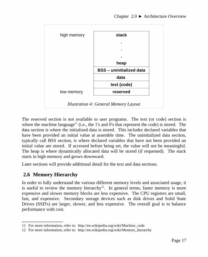
2.5 Memory Layout
The general memory layout for a program is as shown:
Page 16
variablename
value Address(in hex)
? 0100100C
00 0100100B
4C 0100100A
4B 01001009
var1 → 40 01001008
? 01001007
Illustration 3: Little Endian Data Layout
Chapter 2.0 ► Architecture Overview
The reserved section is not available to user programs. The text (or code) section iswhere the machine language11 (i.e., the 1's and 0's that represent the code) is stored. Thedata section is where the initialized data is stored. This includes declared variables thathave been provided an initial value at assemble time. The uninitialized data section,typically call BSS section, is where declared variables that have not been provided aninitial value are stored. If accessed before being set, the value will not be meaningful.The heap is where dynamically allocated data will be stored (if requested). The stackstarts in high memory and grows downward.
Later sections will provide additional detail for the text and data sections.
2.6 Memory Hierarchy
In order to fully understand the various different memory levels and associated usage, itis useful to review the memory hierarchy12. In general terms, faster memory is moreexpensive and slower memory blocks are less expensive. The CPU registers are small,fast, and expensive. Secondary storage devices such as disk drives and Solid StateDrives (SSD's) are larger, slower, and less expensive. The overall goal is to balanceperformance with cost.
11 For more information, refer to: http://en.wikipedia.org/wiki/Machine_code12 For more information, refer to: http://en.wikipedia.org/wiki/Memory_hierarchy
Page 17
high memory stack
.
.
.
heap
BSS – uninitialized data
data
text (code)
low memory reserved
Illustration 4: General Memory Layout
Chapter 2.0 ◄ Architecture Overview
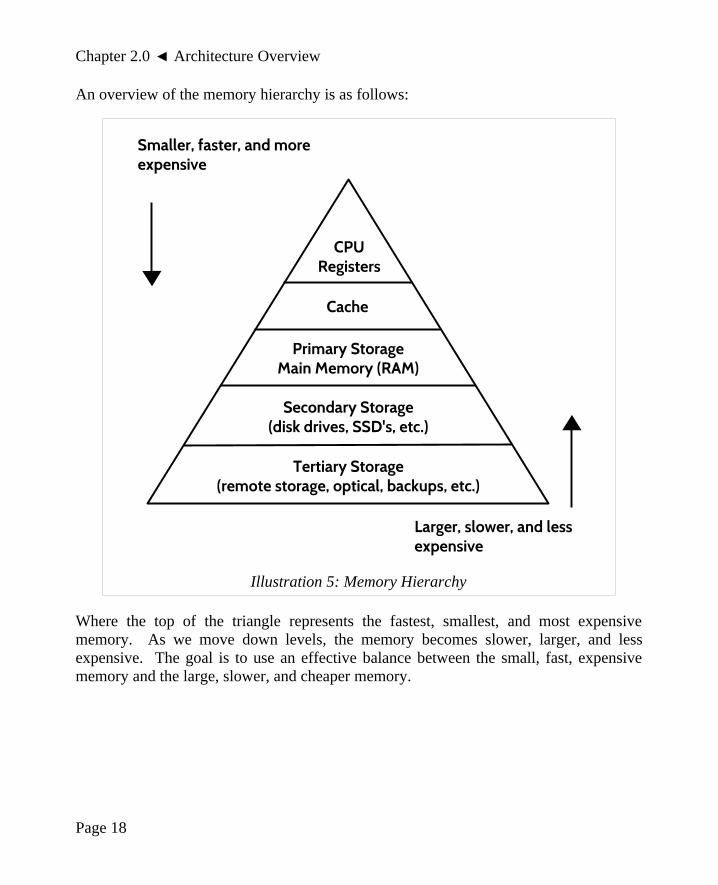
An overview of the memory hierarchy is as follows:
Where the top of the triangle represents the fastest, smallest, and most expensivememory. As we move down levels, the memory becomes slower, larger, and lessexpensive. The goal is to use an effective balance between the small, fast, expensivememory and the large, slower, and cheaper memory.
Page 18
Illustration 5: Memory Hierarchy
CPURegisters
Cache
Primary StorageMain Memory (RAM)
Secondary Storage(disk drives, SSD's, etc.)
Tertiary Storage(remote storage, optical, backups, etc.)
Smaller, faster, and more expensive
Larger, slower, and less expensive

Chapter 2.0 ► Architecture Overview
Some typical performance and size characteristics are as follows:
Memory Unit Example Size Typical Speed
Registers 16, 64-bit registers ~1 nanoseconds13
Cache Memory 4 - 8+ Megabytes14
(L1 and L2)~5-60 nanoseconds
Primary Storage (i.e., main memory)
2 – 32+ Gigabytes15 ~100-150 nanoseconds
Secondary Storage (i.e., disk, SSD's, etc.)
500 Gigabytes – 4+ Terabytes16
~3-15 milliseconds17
Based on this table, a primary storage access at 100 nanoseconds (100 ´ 10-9) is 30,000times faster than a secondary storage access, at 3 milliseconds (3 ´ 10-3).
The typical speeds improve over time (and these are already out of date). The key pointis the relative difference between each memory unit is significant. This differencebetween the memory units applies even as newer, faster SSDs are being utilized.
2.7 Exercises
Below are some questions based on this chapter.
2.7.1 Quiz Questions
Below are some quiz questions.
1) Draw a picture of the VonNeumann Architecture.
2) What architecture component connects the memory to the CPU?
3) Where are programs stored when the computer is turned off?
4) Where must programs be located when they are executing?
5) How does cache memory help overall performance?
6) How many bytes does a C++ integer declared with the declaration int use?
13 For more information, refer to: http://en.wikipedia.org/wiki/Nanosecond14 For more information, refer to: http://en.wikipedia.org/wiki/Megabyte15 For more information, refer to: http://en.wikipedia.org/wiki/Gigabyte16 For more information, refer to: http://en.wikipedia.org/wiki/Terabyte17 For more information, refer to: http://en.wikipedia.org/wiki/Millisecond
Page 19

Chapter 2.0 ◄ Architecture Overview
7) On the Intel X86-64 architecture, how many bytes can be stored at each address?
8) Given the 32-bit hex 004C4B4016 what is the:
1. Least Significant Byte (LSB)
2. Most Significant Byte (MSB)
9) Given the 32-bit hex 004C4B4016, show the little-endian memory layout showingeach byte in memory.
10) Draw a picture of the layout for the rax register.
11) How many bits does each of the following represent:
1. al
2. rcx
3. bx
4. edx
5. r11
6. r8b
7. sil
8. r14w
12) Which register points to the next instruction to be executed?
13) Which register points to the current top of the stack?
14) If al is set to 0516 and ax is set to 000716, eax is set to 0000002016, and rax is setto 000000000000000016, and show the final complete contents of the completerax register.
15) If the rax register is set to 81,985,529,216,486,89510 (123456789ABCDEF16),what are the contents of the following registers in hex?
1. al
2. ax
3. eax
4. rax
Page 20

Chapter 2.0 ► Architecture Overview
3.0 Data RepresentationData representation refers to how information is stored within the computer. There is aspecific method for storing integers which is different than storing floating point valueswhich is different than storing characters. This chapter presents a brief summary of theinteger, floating-point, and ASCII representation schemes.
It is assumed the reader is already generally familiar with binary, decimal, and hexnumbering systems.
It should be noted that if not specified, a number is in base-10. Additionally, a numberpreceded by 0x is a hex value. For example, 19 = 1910 = 1316 = 0x13.
3.1 Integer Representation
Representing integer numbers refers to how the computer stores or represents a numberin memory. The computer represents numbers in binary (1's and 0's). However, thecomputer has a limited amount of space that can be used for each number or variable.This directly impacts the size, or range, of the number that can be represented. Forexample, a byte (8 bits) can be used to represent 28 or 256 different numbers. Those 256different numbers can be unsigned (all positive) in which case we can represent anynumber between 0 and 255 (inclusive). If we choose signed (positive and negativevalues), then we can represent any number between -128 and +127 (inclusive).
If that range is not large enough to handle the intended values, a larger size must beused. For example, a word (16 bits) can be used to represent 216 or 65,536 differentvalues, and a double-word (32-bits) can be used to represent 232 or 4,294,967,296different numbers. So, if you wanted to store a value of 100,000 then a double-wordwould be required.
Page 21
Chapter3
There are 10 types of people in the world; those that understand binary and those that don't.

Chapter 3.0 ◄ Data Representation
As you may recall from C, C++, or Java, an integer declaration (e.g., int <variable>) isa single double-word which can be used to represent values between -231
(−2,147,483,648) and +231 - 1 (+2,147,483,647).
The following table shows the ranges associated with typical sizes:
Size Size Unsigned Range Signed Range
Bytes (8 bits) 28 0 to 255 -128 to +127
Words (16 bits) 216 0 to 65,535 −32,768 to +32,767
Double-words (32 bits) 232 0 to 4,294,967,295 −2,147,483,648 to+2,147,483,647
Quadword 264 0 to 264 - 1 -(263) to 263 - 1
Double quadword 2128 0 to 2128 - 1 -(2127) to 2127 - 1
In order to determine if a value can be represented, you will need to know the size of thestorage element (byte, word, double-word, quad word, etc.) being used and if the valuesare signed or unsigned.
• For representing unsigned values within the range of a given storage size,standard binary is used.
• For representing signed values within the range, two's complement is used.Specifically, the two's complement encoding process applies to the values in thenegative range. For values within the positive range, standard binary is used.
For example, the unsigned byte range can be represented using a number line as follows:
For example, the signed byte range can also be represented using a number line as follows:
The same concept applies to halfwords and words which have larger ranges.
Page 22
2550
-128 0 +127

Chapter 3.0 ► Data Representation
Since unsigned values have a different, positive only, range than signed values, there isoverlap between the values. This can be very confusing when examining variables inmemory (with the debugger).
For example when the unsigned and signed values are within the overlapping positiverange (0 to +127):
• A signed byte representation of 1210 is 0x0C16 • An unsigned byte representation of 1210 is also 0x0C16
When the unsigned and signed values are outside the overlapping range:
• A signed byte representation of -1510 is 0xF116 • An unsigned byte representation of 24110 is also 0xF116
This overlap can cause confusion unless the data types are clearly and correctly defined.
3.1.1 Two's Complement
The following describes how to find the two's complement representation for negativevalues (not positive values).
To take the two's complement of a number:
1. take the one's complement (negate)
2. add 1 (in binary)
The same process is used to encode a decimal value into two's complement and fromtwo's complement back to decimal. The following sections provide some examples.
3.1.2 Byte Example
For example, to find the byte size (8-bits), two's complement representation of -9 and-12.
9 (8+1) = 00001001 12 (8+4) = 00001100
Step 1 11110110 Step 1: 11110011
Step 2 11110111 11110100
-9 (in hex) = F7 -12 (in hex) = F4
Note, all bits for the given size, byte in this example, must be specified.
Page 23

Chapter 3.0 ◄ Data Representation
3.1.3 Word Example
To find the word size (16-bits), two's complement representation of -18 and -40.
18 (16+2) = 0000000000010010 40 (32+8) = 0000000000101000
Step 1 1111111111101101 Step 1 1111111111010111
Step 2 1111111111101110 Step 2 1111111111011000
-18 (hex) = 0xFFEE -40 (hex) = 0xFFD8
Note, all bits for the given size, words in these examples, must be specified.
3.2 Unsigned and Signed Addition
As previously noted, the unsigned and signed representations may provide differentinterpretations for the final value being represented. However, the addition andsubtraction operations are the same. For example:
241 11110001 -15 11110001
+ 7 00000111 + 7 00000111
248 11111000 -8 11111000
248 = F8 -8 = F8
The final result of 0xF8 may be interpreted as 248 for unsigned representation and -8 fora signed representation. Additionally, 0xF816 is the º (degree symbol) in the ASCIItable.
As such, it is very important to have a clear definition of the sizes (byte, halfword, word,etc.) and types (signed, unsigned) of data for the operations being performed.
3.3 Floating-point Representation
The representation issues for floating points numbers are more complex. There are aseries of floating point representations for various ranges of the value. For simplicity,we will look primarily at the IEEE 754 32-bit floating-point standard.
Page 24

Chapter 3.0 ► Data Representation
3.3.1 IEEE 32-bit Representation
The IEEE 754 32-bit floating-point standard is defined as follows:
31 30 29 28 27 26 25 24 23 22 21 20 19 18 17 16 15 14 13 12 11 10 9 8 7 6 5 4 3 2 1 0
s biased exponent fraction
Where s is the sign (0 => positive and 1 => negative). More formally, this can bewritten as;
N = (−1)S× 1. F × 2E−127
When representing floating point values, the first step is to convert floating point valueinto binary. The following table provides a brief reminder of how binary handlesfractional components:
23 22 21 20 2-1 2-2 2-3
... 8 4 2 1 . 1/2 1/4 1/8 ...
0 0 0 0 . 0 0 0
For example, 100.1012 would be 4.62510. For repeating decimals, calculating the binaryvalue can be time consuming. However, there is a limit since computers have finitestorage sizes (32-bits in this example).
The next step is to show the value in normalized scientific notation in binary. Thismeans that the number should have a single, non-zero leading digit to the left of thedecimal point. For example, 8.12510 is 1000.0012 (or 1000.0012 x 20) and in binarynormalized scientific notation that would be written as 1.000001 x 23 (since the decimalpoint was moved three places to the left). Of course, if the number was 0.12510 thebinary would be 0.0012 (or 0.0012 x 20) and the normalized scientific notation would be1.0 x 2-3 (since the decimal point was moved three places to the right). The numbersafter the leading 1, not including the leading 1, are stored left-justified in the fractionportion of the double-word.
The next step is to calculate the biased exponent, which is the exponent from thenormalized scientific notation with plus the bias. The bias for the IEEE 754 32-bitfloating-point standard is 12710. The result should be converted to a byte (8 bits) andstored in the biased exponent portion of the word.
Page 25

Chapter 3.0 ◄ Data Representation
Note, converting from the IEEE 754 32-bit floating-point representation to the decimalvalue is done in reverse, however leading 1 must be added back (as it is not stored in theword). Additionally, the bias is subtracted (instead of added).
3.3.1.1 IEEE 32-bit Representation Examples
This section presents several examples of encoding and decoding floating-pointrepresentation for reference.
3.3.1.1.1 Example → -7.7510
For example, to find the IEEE 754 32-bit floating-point representation for -7.7510:
Example 1: -7.75• determine sign -7.75 => 1 (since negative)• convert to binary -7.75 = -0111.112
• normalized scientific notation = 1.1111 x 22
• compute biased exponent 210 + 12710 = 12910 ◦ and convert to binary = 100000012
• write components in binary:sign exponent mantissa 1 10000001 11110000000000000000000
• convert to hex (split into groups of 4) 11000000111110000000000000000000 1100 0000 1111 1000 0000 0000 0000 0000 C 0 F 8 0 0 0 0
• final result: C0F8 000016
3.3.1.1.2 Example → -0.12510
For example, to find the IEEE 754 32-bit floating-point representation for -0.12510:
Example 2: -0.125• determine sign -0.125 => 1 (since negative)• convert to binary -0.125 = -0.0012
• normalized scientific notation = 1.0 x 2-3
• compute biased exponent -310 + 12710 = 12410 ◦ and convert to binary = 011111002
• write components in binary:sign exponent mantissa 1 01111100 00000000000000000000000
Page 26

Chapter 3.0 ► Data Representation
• convert to hex (split into groups of 4) 10111110000000000000000000000000 1011 1110 0000 0000 0000 0000 0000 0000 B E 0 0 0 0 0 0
• final result: BE00 000016
3.3.1.1.3 Example → 4144000016
For example, given the IEEE 754 32-bit floating-point representation 4144000016 findthe decimal value:
Example 3: 4144000016
• convert to binary 0100 0001 0100 0100 0000 0000 0000 00002
• split into components 0 10000010 100010000000000000000002
• determine exponent 100000102 = 13010 ◦ and remove bias 13010 - 12710 = 310
• determine sign 0 => positive• write result +1.10001 x 23 = +1100.01 = +12.25
3.3.2 IEEE 64-bit Representation
The IEEE 754 64-bit floating-point standard is defined as follows:
63 62 52 51 0
s biased exponent fraction
The representation process is the same, however the format allows for an 11-bit biasedexponent (which support large and smaller values). The 11-bit biased exponent uses abias of ±1023.
3.3.3 Not a Number (NaN)
When a value is interpreted as a floating point value and it does not conform to thedefined standard (either for 32-bit or 64-bit), then it can not be used as a floating pointvalue. This might occur if an integer representation is treated as a floating pointrepresentation or a floating-point arithmetic operation (add, subtract, multiple, ordivide) results in a value that is too large or too small to be represented. The incorrectformat or unrepresentable number is referred to as a NaN which is an abbreviation fornot a number.
Page 27

Chapter 3.0 ◄ Data Representation
3.4 Characters and Strings
In addition to numeric data, symbolic data is often required. Symbolic or non-numericdata might include an important message such as “Hello World”18 a common greetingfor first programs. Such symbols are well understood by English language speakers.Computer memory is designed to store and retrieve numbers. Consequently, thesymbols are represented by assigning numeric values to each symbol or character.
3.4.1 Character Representation
In a computer, a character19 is a unit of information that corresponds to a symbol such asa letter in the alphabet. Examples of characters include letters, numerical digits,common punctuation marks (such as "." or "!"), and whitespace. The general conceptalso includes control characters, which do not correspond to symbols in a particularlanguage, but to other information used to process text. Examples of control charactersinclude carriage return or tab.
3.4.1.1 American Standard Code for Information Interchange
Characters are represented using the American Standard Code for InformationInterchange (ASCII20). Based on the ASCII table, each character and control characteris assigned a numeric value. When using ASCII, the character displayed is based on theassigned numeric value. This only works if everyone agrees on common values, whichis the purpose of the ASCII table. For example, the letter “A” is defined as 65 10 (0x41).The 0x41 is stored in computer memory, and when displayed to the console, the letter“A” is shown. Refer to Appendix A for the complete ASCII table.
Additionally, numeric symbols can be represented in ASCII. For example, “9” isrepresented as 5710 (0x39) in computer memory. The “9” can be displayed as output tothe console. If sent to the console, the integer value 910 (0x09) would be interpreted asan ASCII value which in the case would be a tab.
It is very important to understand the difference between characters (such as “2”) andintegers (such a 210). Characters can be displayed to the console, but can not be used forcalculations. Integers can be used for calculations, but can not be displayed to theconsole (without changing the representation).
A character is typically stored in a byte (8-bits) of space. This works well since memoryis byte addressable.
18 For more information, refer to: http://en.wikipedia.org/wiki/”Hello,_World!”_program19 For more information, refer to: http://en.wikipedia.org/wiki/Character_(computing)20 For more information, refer to: http://en.wikipedia.org/wiki/ASCII
Page 28

Chapter 3.0 ► Data Representation
3.4.1.2 Unicode
It should be noted that Unicode21 uses 2 bytes for each character. The additional spacesupports a much wider range of characters which allows for many non-Englishlanguages. Details regarding Unicode representation are not addressed in this text.
3.4.2 String Representation
A string22 is a series of ASCII characters, typically terminated with a NULL. TheNULL is a non-printable ASCII control character. Since it is not printable, it can beused to mark the end of a string.
For example, the string “Hello” would be represented as follows:
Character “H” “e” “l” “l” “o” NULL
ASCII Value (decimal) 72 101 108 108 111 0
ASCII Value (hex) 0x48 0x65 0x6C 0x6C 0x6F 0x0
A string may consist partially or completely of numeric symbols. For example, thestring “19653” would be represented as follows:
Character “1” “9” “6” “5” “3” NULL
ASCII Value (decimal) 49 57 54 53 51 0
ASCII Value (hex) 0x31 0x39 0x36 0x35 0x33 0x0
Again, it is very important to understand the difference between the string “19653”(using 6 bytes) and the single integer 19,65310 (which can be stored in a single wordwhich is 2 bytes).
3.5 Exercises
Below are some questions based on this chapter.
21 For more information, refer to: http://en.wikipedia.org/wiki/Unicode22 For more information, refer to: http://en.wikipedia.org/wiki/String_(computer_science)
Page 29

Chapter 3.0 ◄ Data Representation
3.5.1 Quiz Questions
Below are some quiz questions.
1) Provide the range for each of the following:
1. signed byte
2. unsigned byte
3. signed word
4. unsigned word
5. signed double-word
6. unsigned double-word
2) Provide the decimal values of the following binary numbers:
1. 00001012
2. 00010012
3. 00011012
4. 00101012
3) Provide the hex, byte size, two's complement values of the following decimalvalues. Note, two hex digits expected.
1. -310
2. +1110
3. -910
4. -2110
4) Provide the hex, word size, two's complement values of the following decimalvalues. Note, four hex digits expected.
1. -1710
2. +1710
3. -3110
4. -13810
Page 30

Chapter 3.0 ► Data Representation
5) Provide the hex, double-word size, two's complement values of the followingdecimal values. Note, eight hex digits expected.
1. -1110
2. -2710
3. +710
4. -26110
6) Provide the decimal values of the following hex, double-word sized, two'scomplement values.
1. FFFFFFFB16
2. FFFFFFEA16
3. FFFFFFF316
4. FFFFFFF816
7) Which of the following decimal values has an exact representation in binary?
1. 0.1
2. 0.2
3. 0.3
4. 0.4
5. 0. 5
8) Provide the decimal representation of the following IEEE 32-bit floating pointvalues.
1. 0xC1440000
2. 0x41440000
3. 0xC0D00000
4. 0xC0F00000
Page 31
Chapter 3.0 ◄ Data Representation
9) Provide hex, IEEE 32-bit floating point representation of the following floatingpoint values.
1. +11.2510
2. -17.12510
3. +21.87510
4. -0.7510
10) What is the ASCII code, in hex, for each of the following characters:
1. “A”
2. “a”
3. “0”
4. “8”
5. tab
11) What are the ASCII values, in hex, for each of the following strings:
1. “World”
2. “123”
3. “Yes!?”
Page 32

4.0 Program FormatThis chapter summarizes the formatting requirements for assembly-language programs.The formatting requirements are specific to the yasm assembler. Other assemblers maybe slightly different. A complete assembly language program is presented todemonstrate the appropriate program formatting.
A properly formatted assembly source file consists of several main parts;
• Data section where initialized data is declared and defined.
• BSS section where uninitialized data is declared.
• Text section where code is placed.
The following sections summarize the basic formatting requirements. Only the basicformatting and assembler syntax are presented. For additional information, refer to theyasm reference manual (as noted in Chapter 1, Introduction).
4.1 Comments
The semicolon (;) is used to note program comments. Comments (using the ;) may beplaced anywhere, including after an instruction. Any characters after the ; are ignoredby the assembler. This can be used to explain steps taken in the code or to comment outsections of code.
4.2 Numeric Values
Number values may be specified in decimal, hex, or octal.
When specifying hex, or base-16 values, they are preceded with a 0x. Forexample, to specify 127 as hex, it would be 0x7f.
When specifying octal, or-base-8 values, they are followed by a q. For example,to specify 511 as octal, it would be 777q.
Page 33
Chapter4
I would love to change the world, but they won't give me the source code.

Chapter 4.0 ◄ Program Format
The default radix (base) is decimal, so no special notation is required for decimal (base-10) numbers.
4.3 Defining Constants
Constants are defined with equ. The general format is:
<name> equ <value>
The value of a constant can not be changed during program execution.
The constants are substituted for their defined values during the assembly process. Assuch, a constant is not assigned a memory location. This makes the constant moreflexible since it is not assigned a specific type/size (byte, word, double-word, etc.). Thevalues are subject to the range limitations of the intended use. For example, thefollowing constant,
SIZE equ 10000
could be used as a word or a double-word, but not a byte.
4.4 Data Section
The initialized data must be declared in the "section .data" section. There must be aspace after the word 'section'. All initialized variables and constants are placed in thissection. Variable names start with a letter followed by letters or numbers includingsome special characters (such as the underscore, "_"). Variable definitions must includethe name, the data type, and the initial value for the variable.
The general format is:
<variableName> <dataType> <initialValue>
Refer to the following sections for a series of examples using various data types.
The supported data types are as follows:
Declaration
db 8-bit variable(s)
dw 16-bit variable(s)
Page 34

Chapter 4.0 ► Program Format
dd 32-bit variable(s)
dq 64-bit variable(s)
ddq 128-bit variable(s) → integer
dt 128-bit variable(s) → float
These are the primary assembler directives for initialized data declarations. Otherdirectives are referenced in different sections.
Initialized arrays are defined with comma separated values.
Some simple examples include:
bVar db 10 ; byte variablecVar db "H" ; single characterstr db "Hello World" ; stringwVar dw 5000 ; word variabledVar dd 50000 ; 32-bit variablearr dd 100, 200, 300 ; 3 element arrayflt1 dd 3.14159 ; 32-bit floatqVar dq 1000000000 ; 64-bit variable
The value specified must be able to fit in the specified data type. For example, if thevalue of a byte sized variables is defined as 500, it would generate an assembler error.
4.5 BSS Section
Uninitialized data is declared in the "section .bss" section. There must be a space afterthe word 'section'. All uninitialized variables are declared in this section. Variablenames start with a letter followed by letters or numbers including some specialcharacters (such as the underscore, "_"). Variable definitions must include the name, thedata type, and the count.
The general format is:
<variableName> <resType> <count>
Refer to the following sections for a series of examples using various data types.
The supported data types are as follows:
Page 35

Chapter 4.0 ◄ Program Format
Declaration
resb 8-bit variable(s)
resw 16-bit variable(s)
resd 32-bit variable(s)
resq 64-bit variable(s)
resdq 128-bit variable(s)
These are the primary assembler directives for uninitialized data declarations. Otherdirectives are referenced in different sections.
Some simple examples include:
bArr resb 10 ; 10 element byte arraywArr resw 50 ; 50 element word arraydArr resd 100 ; 100 element double arrayqArr resq 200 ; 200 element quad array
The allocated array is not initialized to any specific value.
4.6 Text Section
The code is placed in the "section .text" section. There must be a space after the word'section'. The instructions are specified one per line and each must be a valid instructionwith the appropriate required operands.
The text section will include some headers or labels that define the initial program entrypoint. For example, assuming a basic program using the standard system linker, thefollowing declarations must be included.
global _start_start:
No special label or directives are required to terminate the program. However, a systemservice should be used to inform the operating system that the program should beterminated and the resources, such as memory, recovered and re-utilized. Refer to theexample program in the following section.
Page 36

Chapter 4.0 ► Program Format
4.7 Example Program
A very simple assembly language program is presented to demonstrate the appropriateprogram formatting.
; Simple example demonstrating basic program; format and layout.
; ************************************************; Some basic data declarations
section .data
; -----; Define constants
EXIT_SUCCESS equ 0 ; successful operationSYS_exit equ 60 ; call code for terminate
; -----; Byte (8-bit) variable declarations
bVar1 db 17bVar2 db 9bResult db 0
; -----; Word (16-bit) variable declarations
wVar1 dw 17000wVar2 dw 9000wResult dw 0
; -----; Double-word (32-bit) variable declarations
dVar1 dd 17000000dVar2 dd 9000000dResult dd 0
Page 37

Chapter 4.0 ◄ Program Format
; -----; Quad-word (64-bit) variable declarations
qVar1 dq 170000000qVar2 dq 90000000qResult dq 0
; *************************************************************; Code Section
section .textglobal _start_start:
; Performs a series of very basic addition operations; to demonstrate basic program format.
; ----------; Byte example; bResult = bVar1 + bVar2
mov al, byte [bVar1]add al, byte [bVar2]mov byte [bResult], al
; ----------; Word example; wResult = wVar1 + wVar2
mov ax, word [wVar1]add ax, word [wVar2]mov word [wResult], ax
; ----------; Double-word example; dResult = dVar1 + dVar2
mov eax, dword [dVar1]add eax, dword [dVar2]mov dword [dResult], eax
Page 38

Chapter 4.0 ► Program Format
; ----------; Quadword example; qResult = qVar1 + qVar2
mov rax, qword [qVar1]add rax, qword [qVar2]mov qword [qResult], rax
; ************************************************************; Done, terminate program.
last:mov rax, SYS_exit ; Call code for exitmov rdi, EXIT_SUCCESS ; Exit program with successsyscall
This example program will be referenced and further explained in the followingchapters.
4.8 Exercises
Below are some questions based on this chapter.
4.8.1 Quiz Questions
Below are some quiz questions.
1) What is the name of the assembler being used in this chapter?
2) How are comments marked in an assembly language program?
3) What is the name of the section where the initialized data declared?
4) What is the name of the section where the uninitialized data declared?
5) What is the name of the section where the code is placed?
6) What is the data declaration for each of the following variables with the givenvalues:
1. byte sized variable bNum set to 1010
2. word sized variable wNum set to 10,29110
3. double-word sized variable dwNum set to 2,126,01010
4. quad word sized variable qwNum set to 10,000,000,00010
Page 39

Chapter 4.0 ◄ Program Format
7) What is the uninitialized data declaration for each of the following:
1. byte sized array named bArr with 100 elements
2. word sized array named wArr with 3000 elements
3. double-word sized array named dwArr with 200 elements
4. quad word sized array named qArr with 5000 elements
8) What are the required declarations to signify the start of a program (in the textsection)?
Page 40

5.0 Tool ChainIn general, the set of programming tools used to create a program is referred to as thetool chain23. For the purposes of this text, the tool chain consists of the following;
• Assembler
• Linker
• Loader
• Debugger
While there are many options for the tool chain, this text uses a fairly standard set ofopen-source tools that work well together and fully support the x86 64-bit environment.
Each of these programming tools is explained in the following sections.
5.1 Assemble/Link/Load Overview
In broad terms, the assemble, link, and load process is how programmer written sourcefiles are converted into an executable program.
The human readable source file is converted into an object file by the assembler. In themost basic form, the object file is converted into an executable file by the linker. Theloader will load the executable file into memory.
23 For more information, refer to: http://en.wikipedia.org/wiki/Toolchain
Page 41
Chapter5
There are two ways to write error-free programs; only the third works.

Chapter 5.0 ◄ Tool Chain
An overview of the process is provided in the following diagram.
The assemble, link, and load steps are described in more detail in the following sections.
Page 42
Illustration 6: Overview: Assemble, Link, Load
AssemblyLanguage
SourceFile
ASSEMBLE
ListFile
ObjectFile
LINK
LOAD
ExecutableFile
RAM
OtherObject
Files(if any)
LibraryRoutines(if any)
SharedObject
Files(if any)

Chapter 5.0 ► Tool Chain
5.2 Assembler
The assembler24 is a program that will read an assembly language input file and convertthe code into a machine language binary file. The input file is an assembly languagesource file containing assembly language instructions in human readable form. Themachine language output is referred to as an object file. As part of this process, thecomments are removed, and the variable names and labels are converted intoappropriate addresses (as required by the CPU during execution).
The assembler used in this text is the yasm assembler. Links to the yasm web site anddocumentation can be found in Chapter 1, Introduction
5.2.1 Assemble Commands
The appropriate yasm assembler command for reading the assembly language sourcefile, such as the example from the previous chapter, is as follows:
yasm -g dwarf2 -f elf64 example.asm -l example.lst
Note, the -l is a dash lower-case letter L (which is easily confused with the number 1).
The -g dwarf2 option is used to inform the assembler to include debugging informationin the final object file. This increases the size of the object file, but is necessary to alloweffective debugging. The -f elf64 informs the assembler to create the object file in theELF6425 format which is appropriate for 64-bit, Linux based systems. Theexample.asm is the name of the assembly language source file for input. The -lexample.lst (dash lower-case letter L) informs the assembler to create a list file namedexample.lst.
If an error occurs during the assembly process, it must be resolved before continuing tothe link step.
5.2.2 List File
In addition, the assembler is optionally capable of creating a list file. The list file showsthe line number, the relative address, the machine language version of the instruction(including variable references), and the original source line. The list file can be usefulwhen debugging.
24 For more information, refer to: http://en.wikipedia.org/wiki/Assembler_(computing)#Assembler25 For more information, refer to: http://en.wikipedia.org/wiki/Executable_and_Linkable_Format
Page 43

Chapter 5.0 ◄ Tool Chain
For example, a fragment from the list file data section, from the example program in theprevious chapter is as follows:
36 00000009 40660301 dVar1 dd 17000000 37 0000000D 40548900 dVar2 dd 9000000 38 00000011 00000000 dResult dd 0
On the first line, the 36 is the line number. The next number, 0x00000009, is therelative address in the data area of where that variable will be stored. Since dVar1 is adouble-word, which requires four bytes, the address for the next variable is0x0000000D. The dVar1 variable uses 4 bytes as addresses 0x00000009, 0x0000000A,0x0000000B, and 0x0000000C. The rest of the line is the data declaration as typed inthe original assembly language source file.
The 0x40660301 is the value, in hex, as placed in memory. The 17,000,00010 is0x01036640. Recalling that the architecture is little-endian, the least significant byte(0x40) is placed in the lowest memory address. As such, the 0x40 is placed in relativeaddress 0x00000009, the next byte, 0x66, is placed in address 0x00000009 and so forth.This can be confusing as at first glance the number may appear backwards or garbled(depending on how it is viewed).
To help visualize, the memory picture would be as follows:
Page 44
variablename
value address
00 0x00000010
89 0x0000000F
54 0x0000000E
dVar2 → 40 0x0000000D
01 0x0000000C
03 0x0000000B
66 0x0000000A
dVar1 → 40 0x00000009
Illustration 7: Little Endian, Multiple Variable Data Layout

Chapter 5.0 ► Tool Chain
For example, a fragment of the list file text section, excerpted from the exampleprogram in the previous chapter is as follows:
95 last: 96 0000005A 48C7C03C000000 mov rax, SYS_exit 97 00000061 48C7C300000000 mov rdi, EXIT_SUCCESS 98 00000068 0F05 syscall
Again, the numbers to the left are the line numbers. The next number, 0x0000005A, isthe relative address of where the line of code will be placed.
The next number, 0x48C7C03C000000, is the machine language version of theinstruction, in hex, that the CPU reads and understands. The rest of the line is theoriginal assembly language source instruction.
The label, last:, does not have a machine language instruction since the label is used toreference a specific address and is not an executable instruction.
5.2.3 Two-Pass Assembler
The assembler26 will read the source file and convert each assembly languageinstruction, typed by the programmer, into a set of 1's and 0's that the CPU knows to bethat instruction. The 1's and 0's are referred to as machine language. There is a one-to-one correspondence between the assembly language instructions and the binary machinelanguage. This relationship means that machine language, in the form of an executablefile can be converted back into human readable assembly language. Of course, thecomments, variable names, and label names are missing, so the resulting code can bevery difficult to read.
As the assembler reads each line of assembly language, it generates machine code forthat instruction. This will work well for instructions to do not perform jumps.However, for instructions that might change the control flow (e.g., IF statements,unconditional jumps), the assembler is not able to convert the instruction. For example,given the following code fragment:
mov rax, 0jmp skipRest......
skipRest:
26 For more information, refer to: http://en.wikipedia.org/wiki/Assembly_language#Assembler
Page 45

Chapter 5.0 ◄ Tool Chain
This is referred to as a forward reference. If the assembler reads the assembly file oneline at a time, it has not read the line where skipRest is defined. In fact, it does not evenknow for sure if skipRest is defined at all.
This situation can be resolved by reading the assembly source file twice. The entireprocess is referred to as a two-pass assembler. The steps required for each pass aredetailed in the following sections.
5.2.3.1 First Pass
The steps taken on the first pass vary based on the design of the specific assembler.However, some of the basic operations performed on the first pass include thefollowing:
• Create symbol table
• Expand macros
• Evaluate constant expressions
A macro is a program element that is expanded into a set of programmer predefinedinstructions. For more information, refer to Chapter 11, Macros.
A constant expression is an expression composed entirely of constants. Since theexpression is constants only, it can be fully evaluated at assemble time. For example,assuming the constant BUFF is defined, the following instruction contains a constantexpression;
mov rax, BUFF+5
This type of constant expression is used commonly in large or complex programs.
Addresses are assigned to all statements in the program. The symbol table is a listing ortable of all the program symbols, variables names and program labels, and theirrespective addresses in the program.
As appropriate, some assembler directives are processed in the first pass.
5.2.3.2 Second Pass
The steps taken on the second pass vary based on the design of the specific assembler.However, some of the basic operations performed on the second pass include thefollowing:
Page 46

Chapter 5.0 ► Tool Chain
• Final generation of code
• Creation of list file (if requested)
• Create object file
The term code generation refers to the conversion of the programmer provided assemblylanguage instruction into the CPU executable machine language instruction. Due to theone-to-one correspondence, this can be done for instructions that do not use symbols oneither the first or second pass.
It should be noted that, based on the assembler design, much of the code generationmight be done on the first pass or all done on the second pass. Either way, the finalgeneration is performed on the second pass. This will require using the symbol table tocheck program symbols and obtain the appropriate addresses from the table.
The list file, while optional, can be useful for debugging. If requested, it would begenerated on the second pass.
If there are no errors, the final object file is created on the second pass.
5.2.4 Assembler Directives
Assembler directives are instructions to the assembler that direct the assembler to dosomething. This might be formatting or layout. These directives are not translated intoinstructions for the CPU.
5.3 Linker
The linker27, sometimes referred to as linkage editor, will combine one or more objectfiles into a single executable file. Additionally, any routines from user or systemlibraries are included as necessary. The GNU gold linker, ld28, is used. The appropriatelinker command for the example program from the previous chapter is as follows:
ld -g -o example example.o
Note, the -o is a dash lower-case letter O, which is can be confused with the number 0.
The -g option is used to inform the linker to include debugging information in the finalexecutable file. This increases the size of the executable file, but is necessary to alloweffective debugging. The -o example specifies to create the executable file namedexample (with no extension). If the -o <fileName> option is omitted, the output file is
27 For more information, refer to: http://en.wikipedia.org/wiki/Linker_(computing)28 For more information, refer to: http://en.wikipedia.org/wiki/Gold_(linker)
Page 47

Chapter 5.0 ◄ Tool Chain
named a.out (by default). The example.o is the name of the input object file read by thelinker. It should be noted that the executable file could be named anything and does notneed to have the same name as any of the input object files.
5.3.1 Linking Multiple Files
In programming, large problems are typically solved by breaking them into smallerproblems. The smaller problems can be addressed individually, possible by differentprogrammers.
Additional input object files, if any, would be listed, in order, separated with a space. For example, if there are two object files, main.o and funcs.o the link command to createan executable file name example, with debugging information included, would be as follows:
ld -g -o example main.o funcs.o
This would typically be required for larger or more complex programs.
When using functions located in a different, external source file, any function orfunctions not in the current source file must be declared as extern. Variables, such asglobal variables, in other source files can be accessed by using the extern statement aswell, however data is typically transferred as arguments of the function call.
5.3.2 Linking Process
Linking is the fundamental process of combining the smaller solutions into a singleexecutable unit. If any user or system library routines are used, the linker will includethe appropriate routines. The object files and library routines are combined into a singleexecutable module. The machine language code is copied from each object file into asingle executable.
As part of combining the object files, the linker must adjust the relocatable addresses asnecessary. Assuming there are two source files, the main and a secondary source filecontaining some functions, both of which have been assembled into object files main.oand funcs.o. When each file is assembled, the calls to routines outside the file beingassembled are declared with the external assembler directive. The code is not availablefor an external reference and such references are marked as external in the object file.The list file will show an R for such relocatable addresses. The linker must satisfy theexternal references. Additionally, the final location of the external references must beplaced in the code.
Page 48

Chapter 5.0 ► Tool Chain
For example, if the main.o object file calls a function in the funcs.o file, the linker mustupdate the call with the appropriate address as shown in the following illustration.
Here, the function fnc1 is external to the main.o object file and is marked with an R.The actual function fnc1 is in the funcs.o file, which starts its relative addressing from0x0 (in the text section) since it does not know about the main code. When the objectfiles are combined, the original relative address of fnc1 (shown as 0x0100:) is changedto its final address in executable file (shown as 0x0400:). The linker must insert thisfinal address into the call statement in the main (shown as call 0x0400:) in order tocomplete the linking process and ensure the function call will work correctly.
This will occur with all relocatable addresses for both code and data.
Page 49
Illustration 8: Linking Multiple Files
main.o
...call fnc1-R
…
funcs.o
...Fnc1-R: 0x0100:
…
executable
call 0x0400
...0x0400:
…

Chapter 5.0 ◄ Tool Chain
5.3.3 Dynamic Linking
The Linux operating system supports dynamic linking29, which allows for postponingthe resolution of some symbols until a program is being executed. The actualinstructions are not placed in executable file and instead, if needed, resolved andaccessed at run-time.
While more complex, this approach offers two advantages:
• Often-used libraries (for example the standard system libraries) can be stored inonly one location, not duplicated in every single binary.
• If a bug in a library function is corrected, all programs using it dynamically willbenefit from the correction (at the next execution). Otherwise, programs thatutilize this function by static linking would have to be re-linked before thecorrection is applied.
There are also disadvantages:
• An incompatible updated library will break executables that depended on thebehavior of the previous version of the library.
• A program, together with the libraries it uses, might be certified (e.g. as tocorrectness, documentation requirements, or performance) as a package, but notif components can be replaced.
In Linux/Unix, the dynamically linked object files typically a have .so (shared object)extension. In Windows, they have a .dll (dynamically linked library) extension.Further details of dynamic linking are outside the scope of this text.
5.4 Assemble/Link Script
When programming, it is often necessary to type the assemble and link commands manytimes with various different programs. Instead of typing the assemble (yasm) and link(ld) commands each time, it is possible to place them in a file, called a script file. Then,the script file can be executed which will just execute the commands that were enteredin the file. While not required, using a script file can save time and make things easierwhen working on a program.
29 For more information, refer to: http://en.wikipedia.org/wiki/Dynamic_linker
Page 50

Chapter 5.0 ► Tool Chain
A simple example bash30 assemble/link script is as follows:
#!/bin/bash# Simple assemble/link script.
if [ -z $1 ]; then echo "Usage: ./asm <asmMainFile> (no extension)" exit
fi
# Verify no extensions were entered
if [ ! -e "$1.asm" ]; then echo "Error, $1.asm not found." echo "Note, do not enter file extensions." exit
fi
# Compile, assemble, and link.
yasm -Worphan-labels -g dwarf2 -f elf64 $1.asm -l $1.lst ld -g -o $1 $1.o
The above script should be placed in a file. For this example, the file will be namedasm64 and placed in the current working directory (where the source files are located).
Once created, execute privilege will need to be added to the script file as follows:
chmod +x asm64
This will only need to be done once for each script file.
The script file will read the source file name from the command line. For example, touse the script file to assemble the example from the previous chapter (namedexample.asm), type the following:
./asm64 example
The ".asm" extension on the example.asm file should not be included (since it is addedin the script). The script file will assemble and link the source file, creating the list file,object file, and executable file.
30 For more information, refer to: http://en.wikipedia.org/wiki/Bash_(Unix_shell)
Page 51

Chapter 5.0 ◄ Tool Chain
Use of this, or any script file, is optional. The name of the script file can be changed asdesired.
5.5 Loader
The loader31 is a part of the operating-system that will load the program from secondarystorage into primary storage (i.e., main memory). In broad terms, the loader willattempt to find, and if found, read a properly formatted executable file, create a newprocess, and load the code into memory and mark the program as ready for execution.The operating-system scheduler will make the decisions about which process isexecuted and when the process is executed.
The loader is implicitly invoked by typing the program name. For example, on theprevious example program, named example, the Linux command would be:
./example
which will execute the file named example created via the previous steps (assemble andlink). Since the example program does not perform any output, nothing will bedisplayed to the console. As such, a debugger can be used to check the results.
5.6 Debugger
The debugger32 is used to control execution of a program. This allows for testing anddebugging activities to be performed.
In the previous example, the program computed a series of calculations, but did notoutput any of the results. The debugger can be used to check the results. Theexecutable file is created with the assemble and link command previously described andmust include the -g option.
The debugger used is the GNU DDD debugger which provides a visual front-end for theGNU command line debugger, gdb. The DDD web site and documentation are noted inthe references section of Chapter 1, Introduction.
The ddd debugger is started with the executable file. For example, using the previoussample program, example, the command would be:
ddd example
31 For more information, refer to: http://en.wikipedia.org/wiki/Loader_(computing)32 For more information, refer to: http://en.wikipedia.org/wiki/Debugger
Page 52

Chapter 5.0 ► Tool Chain
Due to the complexity and importance of the debugger, a separate chapter for thedebugging is provided.
5.7 Exercises
Below are some questions based on this chapter.
5.7.1 Quiz Questions
Below are some quiz questions.
1) What is the relationship between assembly language and machine language?
2) What actions are performed on the first-pass of the assembler?
3) What actions are performed on the second-pass of the assembler?
4) What actions are performed by the linker?
5) What actions are performed by the loader?
6) Provide an example of a constant expression.
7) Draw a diagram of the entire assemble, link, and load process.
8) When is a shared object file linked with a program?
9) What is contained in the symbol table (two things)?
Page 53

Chapter 5.0 ◄ Tool Chain
Page 54

6.0 DDD Debugger A debugger allows the user to control execution of a program, examine variables, othermemory (i.e., stack space), and display program output (if any). The open source GNUData Display Debugger (DDD33) is a visual front-end to the GNU Debugger (GDB34)debugger and is widely available. Other debuggers can easily be used if desired.
Only the basic debugger commands are addressed in this chapter. The DDD debuggerhas many more features and options not covered here. As you gain experience, it wouldbe worth reviewing the DDD documentation, referenced in Chapter 1, to learn moreabout additional features in order to help improve overall debugging efficiency.
DDD functionality can be extended using various plug-ins. The plug-ins are notrequired and will not be addressed in this Chapter.
This chapter addresses using the GNU DDD debugger as a tool. The logical process ofhow to debug a program is not addressed in this chapter.
6.1 Starting DDD
The ddd debugger is started with the executable file. The program must be assembledand linked with the correct options (as noted in the previous chapter). For example,using the previous sample program, example, the command would be:
ddd example
Upon starting DDD/GDB, something similar to the screen, shown below, should bedisplayed (with the appropriate source code displayed).
33 For more information, refer to: http://en.wikipedia.org/wiki/Data_Display_Debugger34 For more information, refer to: http://en.wikipedia.org/wiki/GNU_Debugger
Page 55
Chapter6
My software never has bugs. It just develops random features.

Chapter 6.0 ◄ DDD Debugger
Illustration 9: Initial Debugger Screen
If the code is not displayed in a similar manner as shown above, the assemble and linksteps should be verified. Specifically, the -g qualifier must be included in both theassemble and link steps.
Built in help is available by clicking on the Help menu item (upper right hand corner).The DDD and GDB manuals are available from the virtual library link on the class webpage. To exit DDD/GDB, select File → Exit (from the top menu bar).
Page 56

Chapter 6.0 ► DDD Debugger
6.1.1 DDD Configuration Settings
Some additional DDD/GDB configuration settings suggestions include:
Edit → Preferences → General → Suppress X Warning
Edit → Preferences → Source → Display Source Line Numbers
These are not required, but can make using the debugger easier. If set, the options willbe saved and remembered for successive uses of the debugger (on the same machine).
6.2 Program Execution with DDD
To execute the program, click on the Run button from the command tool menu (shownbelow). Alternately, you can type run at the (gdb) prompt (bottom GDB consolewindow). However, this will execute the program entirely and, when done, the resultswill be reset (and lost).
6.2.1 Setting Breakpoints
In order to control program execution, it will be necessary to set a breakpoint (executionpause location) to pause the program at a user selected location. This can be done byselecting the source location (line to stop at). For this example, we will stop at line 31.
The breakpoint can be done one of three ways:
• Right click on the line number and select: Set Breakpoint
• In the GDB Command Console, at the (gdb) prompt, type: break last
• In the GDB Command Console, at the (gdb) prompt, type: break 31
Page 57

Chapter 6.0 ◄ DDD Debugger
When set correctly, the “stop” icon will appear to the left of line number (as shown inthe diagram).
Illustration 10: Debugger Screen with Breakpoint Set
DDD/GDB commands can be typed inside the bottom window (at the (gdb) prompt) atany time. Multiple breakpoints can be set if desired.
6.2.2 Executing Programs
Once the debugger is started, in order to effectively use the debugger, an initialbreakpoint must be set.
Page 58

Chapter 6.0 ► DDD Debugger
Once the breakpoint is set, the run command can be performed via clicking Run menuwindow or typing run at the (gdb) prompt. The program will execute up to, but notincluding the statement with the green arrow.
Illustration 11: Debugger Screen with Green Arrow
The breakpoint is indicated with the stop sign on the right (see example previous page).The current location is indicated with a green arrow. Specifically, the green arrowpoints to the next instruction to be executed. That is, the statement pointed to by thegreen arrow has not yet been executed.
Page 59

Chapter 6.0 ◄ DDD Debugger
6.2.2.1 Run / Continue
As needed, additional breakpoints can be set. However, click the Run command willre-start execution from the beginning and stop at the initial breakpoint.
After the initial Run command, to continue to the next breakpoint, the continuecommand must be used (by clicking Cont menu window or typing cont at the (gdb)prompt). Single lines can also be executed one line at a time by typing the step or nextcommands (via clicking Step or Next menu window or typing step or next at the (gdb)prompt).
6.2.2.2 Next / Step
The next command will execute to the next instruction. This includes executing anentire function if necessary. The step command will execute one step, stepping intofunctions if necessary. For a single, non-function instruction, there is no differencebetween the next and step commands.
6.2.3 Displaying Register Contents
The simplest method to see the contents of the registers is to use the registers window.The registers window is not displayed by default, but can be viewed by selecting Status→ Registers (from the top menu bar). When displayed, the register window will showregister contents by register name (left column), in both hex (middle column) and signeddecimal (right column).
Page 60
Illustration 12: DDD Command Bar

Chapter 6.0 ► DDD Debugger
Illustration 13: Register Window
Depending on the machine and screen resolution, the register window may need to beresized to view the entire contents.
The third column of the register window generally shows the decimal quadwordrepresentation except for some special purpose registers (rbp and rsp). The signedquadword decimal representation may not always be meaningful. For example, ifunsigned data is being used (such as addresses), the signed representation would beincorrect. Additionally, when character data is used, the signed representation wouldnot be meaningful.
By default, only the integer registers are displayed. Clicking on the “All registers” boxwill add the floating point registers to the display. Viewing will require scrolling downwithin the register window.
Page 61

Chapter 6.0 ◄ DDD Debugger
6.2.4 DDD/GDB Commands Summary
The following table provides a small subset of the most common DDD commands.When typed, most commands may be abbreviated. For example, quit can beabbreviated as q. The command and the abbreviation are shown in the table.
Command Description
quit | q Quit the debugger.
break | b <label/addr> Set a break point (stop point) at <label> or<address>.
run <args> | r <args> Execute the program (to the first breakpoint).
continue | c Continue execution (to the next breakpoint).
step | s Step into next instruction (steps into procedurecalls).
next | n Next instruction (steps through procedure calls).
F3 Re-start program (and stop at first breakpoint).
where Current activation (call depth).
x/<n><f><u> $rsp Examine contents of the stack.
Page 62

Chapter 6.0 ► DDD Debugger
Command Description
x/<n><f><u> &<variable> Examine memory location <variable><n> number of locations to display, 1 isdefault.
<f> format: d – decimal (signed)
x – hex
u – decimal (unsigned)
c – character
s – string
f – floating point
<u> unit size: b – byte (8-bits)
h – halfword (16-bits)
w – word (32-bits)
g – giant (64-bits)
source <filename> Read commands from file <filename>.
set logging file <filename> Set logging file to <filename>, default isgdb.txt.
set logging on Turn logging (to a file) on.
set logging off Turn logging (to a file) off.
set logging overwrite When logging (to a file) is turned on, overwriteprevious log file (if any).
More information can be obtained via the built-in help facility or from thedocumentation on the ddd website (referenced from Chapter 1).
Page 63

Chapter 6.0 ◄ DDD Debugger
6.2.4.1 DDD/GDB Commands, Examples
For example, given the below data declarations:
bnum1 db 5wnum2 dw -2000dnum3 dd 100000qnum dq 1234567890class db "Assembly", 0twopi dd 6.28
Assuming signed data, the examine memory commands would be as follows:
x/db &bnum1x/dh &wnum2x/dw &dnum3x/dg &qnumx/s &classx/f &twopi
If an inappropriate memory dump command is used (i.e., incorrect size), there is noerror message and the debugger will display what was requested (even if it does notmake sense). Examining variables will require use of the appropriate memory dumpcommand based on the data declarations. Additional options can be accessed across themenu at the top of the screen.
To display an array in DDD, the basic examine memory command is used.
x/<n><f><u> &<variable>
For example, assuming the declaration of:
list1 dd 100001, -100002, 100003, 100004, 100005
The examine memory commands would be as follows:
x/5dw &list1
Where the 5 is the array length. The d indicates signed data (u would have beenunsigned data). The w indicates 32-bit sized data (which is what the dd, define double,definition declares in the source file). The &list1 is the name of the variable. Note, thename points to the first element (that all). As such, it is very possible to display less ormore elements that are actually declared in the array.
Page 64

Chapter 6.0 ► DDD Debugger
The basic examine memory command can be used with a memory address directly (asopposed to a variable name). For example:
x/dw 0x600d44
Addresses are typically displayed in hexadecimal, so a 0x would be required in order toenter the hexadecimal address directly as shown.
6.2.5 Displaying Stack Contents
There are some occasions when displaying the contents of the stack may be useful. Thestack is normally comprised of 64-bit, unsigned elements. The examine memorycommand is used, however the address is in the rsp register (not a variable name). Theexamine memory command to display the current top of the stack would be as follows:
x/ug $rsp
The examine memory command to display the top 6 items on the stack would be asfollows:
x/6ug $rsp
Due to the stack implementation, the first item shown will always be current top of thestack.
6.2.6 Debugger Commands File (interactive)
Since the data display commands must be correct (since there is no error), it can betedious. To help reduce errors, the correct execution and display command can bestored in a text file. The debugger can then read the commands from the file (instead oftyping them by hand). While the results are typically displayed the screen, the resultscan be re-directed to an output file. This can be useful for easy review.
For example, some typical debugger commands to set the breakpoint, run the program,display some variables, and redirect the output to a log file might be as follows:
#------------------------------------# Debugger Input Script#------------------------------------echo \n\nbreak lastrunset pagination off
Page 65

Chapter 6.0 ◄ DDD Debugger
set logging file out.txtset logging overwriteset logging onset promptecho ------------------------------------ \necho display variables \necho \nx/100dw &listx/dw &lengthecho \nx/dw &listMinx/dw &listMidx/dw &listMaxx/dw &listSumx/dw &listAveecho \n \nset logging offquit
Note 1; this example assumes a label 'last' is defined in the source program (as isdone on the example program).
Note 2; this example exits the debugger. If that is not desired, the 'quit' commandcan be removed. When exiting from the input file, the debugger may request userconfirmation of the exit (yes or no).
These commands should be placed in a file (such as gdbIn.txt), so they can be read fromwithin the debugger.
6.2.6.1 Debugger Commands File (non-interactive)
The debugger command to read a file is ''source <filename>''. For example, if thecommand file is named gdbIn.txt,
(gdb) source gdbIn.txt
Based on the above commands, the output will be placed in the file out.txt. The outputfile name can be changed as desired.
Each program will require a custom input command set based on the variables andassociated sizes. The debugger input commands file will only be useful when theprogram is fairly close to working. Program crashes and other more significant errorswill require interactive debugging to determine the specific error.
Page 66

Chapter 6.0 ► DDD Debugger
6.2.6.2 Debugger Commands File (non-interactive)
It is possible to obtain the output file directly without an interactive DDD session. Thefollowing command, entered at the command line, will execute the command in theinput file on the given program, create the output file, and exit the program.
gbd <gdbIn.txt prog
Which will create the output file (as specified in the gdbIn.txt file) and exit thedebugger. This is the fastest option for obtaining the final output file for a workingprogram. Again, this would only be useful if the program is working or very close toworking correctly.
6.3 Exercises
Below are some quiz questions based on this chapter.
6.3.1 Quiz Questions
Below are some quiz questions.
1) How is the debugger started (from the command line)?
2) What option is required during the assemble and link step in order to ensure theprogram be easily debugged.
3) What does the run command do specifically?
4) What does the continue command do specifically?
5) How is the register window displayed?
6) There are three columns in the register window. The first shows the register.What do the other two columns show?
7) Once the debugger is started, how can the user exit?
8) Describe how a breakpoint is set (multiple ways).
9) What is the debugger command to read debugger commands from a file?
10) When the DDD shows a green arrow pointing to an instruction, what does thatmean?
Page 67

Chapter 6.0 ◄ DDD Debugger
11) Provide the debugger command to display each of the following variables indecimal.
1. bVar1 (byte sized variable)
2. wVar1 (word sized variable)
3. dVar1 (double-word sized variable)
4. qVar1 (quad word sized variable)
5. bArr1 (30 element array of bytes)
6. wArr1 (50 element array of words)
7. dArr1 (75 element array of double-words)
12) Provide the debugger command to display each of the following variables inhexadecimal format.
1. bVar1 (byte sized variable)
2. wVar1 (word sized variable)
3. dVar1 (double-word sized variable)
4. qVar1 (quad word sized variable)
5. bArr1 (30 element array of bytes)
6. wArr1 (50 element array of words)
7. dArr1 (75 element array of double-words)
13) What is the debugger command to display the value at the current top of thestack?
14) What is the debugger command to display five (5) values at the current top of thestack?
6.3.2 Suggested Projects
Below are some suggested projects based on this chapter.
1) Type in the example program from Chapter 4, Program Format. Assemble andlink the program as described in Chapter 5, Tool Chain. Execute the debugger asnoted in this chapter. Set a breakpoint at the label last and execute the program(to that breakpoint). Interactively verify that the calculations performed resulted
Page 68

Chapter 6.0 ► DDD Debugger
in the correct values. This will require typing the appropriate debugger examinememory commands (based on the variable size).
2) After completing the previous problem, create a debugger input file that will setthe send the output to a text file, set a breakpoint, execute the program, anddisplay the results for each variable (based on the appropriate variable size).Execute the debugger and read the source file. Review the input file workedcorrectly and that the program calculations are correct based on the resultsshown in the output file.
3) Create an assemble and link script file, as described in Chapter 5, Tool Chain.Use the script to assemble and link the program. Ensure that the script correctlyassembles and links.
Page 69

Chapter 6.0 ◄ DDD Debugger
Page 70

7.0 Instruction Set Overview This chapter provides a basic overview for a simple subset of the x86-64 instruction setfocusing on the integer operations. This will cover the only the subset of instructionsrequired for the topics and programs discussed within the scope of this text. This willexclude some of the more advanced instructions and restricted mode instructions. For acomplete listing of all processor instructions, refer to the references listed in Chapter 1.
The instructions are presented in the following order:
• Data Movement
• Conversion Instructions
• Arithmetic Instructions
• Logical Instructions
• Control Instructions
The instructions for function calls are discussed in the chapter in Chapter 12, Functions.
A complete listing of the instructions covered in this text is located in Appendix B forreference.
7.1 Notational Conventions
This section summarizes the notation used within this text which is fairly common in thetechnical literature. In general, an instruction will consist of the instruction or operationitself (i.e., add, sub, mul, etc.) and the operands. The operands refer to where the data(to be operated on) is coming from and/or where the result is to be placed.
Page 71
Chapter7
Why are math books sad?Because they have so many problems.

Chapter 7.0 ◄ Instruction Set Overview
7.1.1 Operand Notation
The following table summarizes the notational conventions used in the remainder of thedocument.
Operand Notation Description
<reg> Register operand. The operand must be a register.
<reg8>, <reg16>,<reg32>, <reg64>
Register operand with specific size requirement. For example, reg8 means a byte sized register (e.g., al, bl, etc.) only and reg32 means a double-word sized register (e.g., eax, ebx, etc.) only.
<dest> Destination operand. The operand may be a register or memory. Since it is a destination operand, the contents will be over written with the new result (based on the specific instruction).
<RXdest> Floating point destination register operand. The operand must be a floating point register. Since it is a destination operand, the contents will be over written with the new result (based on the specific instruction).
<src> Source operand. Operand value is unchanged after the instruction.
<imm> Immediate value. May be specified in decimal, hex, octal,or binary.
<mem> Memory location. May be a variable name or an indirect reference (i.e., a memory address).
<op> or <operand> Operand, register or memory.
<op8>, <op16>,<op32>, <op64>
Operand, register or memory, with specific size requirement. For example, op8 means a byte sized operand only and reg32 means a double-word sized operand only.
<label> Program label.
By default, the immediate values are decimal or base-10. Hexadecimal or base-16immediate values may be used but must be preceded with a 0x to indicate the value ishex. For example, 1510 could be entered in hex as 0x0F.
Page 72

Chapter 7.0 ► Instruction Set Overview
Refer to Chapter 8, Addressing Modes for more information regarding memorylocations and indirection.
7.2 Data Movement
Typically, data must be moved into a CPU register from RAM in order to be operatedupon. Once the calculations are completed, the result may be copied from the registerand placed into a variable. There are a number of simple formulas in the exampleprogram that perform these steps. This basic data movement operation is performedwith the move instruction.
The general form of the move instruction is:
mov <dest>, <src>
The source operand is copied from the source operand into the destination operand. Thevalue of the source operand is unchanged. The destination and source operand must beof the same size (both bytes, both words, etc.). The destination operand can not be animmediate. Both operands can not be memory. If a memory to memory operation isrequired, two instructions must be used.
When the destination register operand is of double-word size and the source operand isof double-word size, the upper-order double-word of the quadword register is set tozero. This only applies when the destination operand is an double-word sized integerregister.
Specifically, if the following operations are performed,
mov eax, 100 ; eax = 0x00000064mov rcx, -1 ; rcx = 0xffffffffffffffffmov ecx, eax ; ecx = 0x00000064
Initially, the rcx register to set to -1 (which is all 0xF's). When the positive numberfrom the eax register (10010) is moved into the rcx register, the upper-order portion of
Page 73
mov eax, dword [myVariable]
what where how much memoryto do to place to get location
Illustration 14: MOV Instruction Overview

Chapter 7.0 ◄ Instruction Set Overview
the quadword register rcx is set to 0 over-writing the 1's from the previous instruction.
The move instruction is summarized as follows:
Instruction Explanation
mov <dest>, <src> Copy source operand to the destination operand.Note 1, both operands can not be memory.Note 2, destination operands can not be an immediate.Note 3, for double-word destination and source operand, the upper-order portion of the quadword register is set to 0.
Examples: mov ax, 42 mov cl, byte [bvar] mov dword [dVar], eax mov qword [qVar], rdx
A more complete list of the instructions is located in Appendix B.
For example, assuming the following data declarations:
dValue dd 0bNum db 42wNum dd 5000dNum dw 73000qNum dw 73000000bAns db 0wAns dw 0dAns dd 0qAns dd 0
To perform, the basic operations of:
dValue = 27bAns = bNumwAns = wNumdAns = dNumqAns = qNum
Page 74

Chapter 7.0 ► Instruction Set Overview
The following instructions could be used:
mov dword [dValue], 27 ; dValue = 27
mov al, byte [bNum]mov byte [bAns], al ; bAns = bNum
mov ax, word [wNum]mov word [wAns], ax ; wAns = wNum
mov eax, dword [dNum]mov dword [dAns], eax ; dAns = dNum
mov rax, qword [qNum]mov qword [qAns], rax ; qAns = qNum
For some instructions, including those above, the explicit type specification (e.g., byte,word, dword, qword) can be omitted as the other operand will clearly define the size. Inthe text it will be included for consistency and good programming practice.
7.3 Addresses vs Values
The only way to access memory is with the brackets ([]'s). Omitting the brackets willnot access memory and instead obtain the address of the item. For example:
mov rax, qword [var1] ; value of var1 in raxmov rax, var1 ; address of var1 in rax
Since omitting the brackets is not an error, the assembler will not generate errormessages or warnings. This can lead to confusion.
In addition, the address of a variable can be obtained with the load effective address, orlea, instruction. The load effective address instruction is summarized as follows:
Instruction Explanation
lea <reg64>, <mem> Place address of <mem> into reg64.
Examples: lea rcx, byte [bvar] lea rsi, dword [dVar]
A more complete list of the instructions is located in Appendix B.
Page 75

Chapter 7.0 ◄ Instruction Set Overview
Additional information and extensive examples are presented in Chapter 8, AddressingModes.
7.4 Conversion Instructions
It is sometimes necessary to convert from one size to another size. For example, a bytemight need to be converted to a double-word for some calculations in a formula. Theprocess used for conversions depends on the size and type of the operand. Thefollowing sections summarize how conversions are performed.
7.4.1 Narrowing Conversions
Narrowing conversions are converting from a larger type to a smaller type (i.e., word tobyte or double-word to word).
No special instructions are needed for narrowing conversions. The lower portion of thememory location or register may be accessed directly. For example, if the value of 50(0x32) is placed in the rax register, the al register may be accessed directly to obtain thevalue as follows:
mov rax, 50mov byte [bVal], al
This example is reasonable since the value of 50 will fit in a byte value. However, if thevalue of 500 (0x1f4) is placed in the rax register, the al register can still be accessed.
mov rax, 500mov byte [bVal], al
In this example, the bVal variable will contain 0xf4 which may lead to incorrect results.The programmer is responsible for ensuring that narrowing conversions are performedappropriately. Unlike a compiler, no warnings or error messages will be generated.
7.4.2 Widening Conversions
Widening conversions are from a smaller type to a larger type (e.g., byte to word orword to double-word). Since the size is being expanded, the upper-order bits must beset based on the sign of the original value. As such, the data type, signed or unsigned,must be known and the appropriate process or instructions must be used.
Page 76

Chapter 7.0 ► Instruction Set Overview
7.4.2.1 Unsigned Conversions
For unsigned widening conversions, the upper part of the memory location or registermust be set to zero. Since an unsigned value can only be positive, the upper-order bitscan only be zero. For example, to convert the byte value of 50 in the al register, to aquadword value in rbx, the following operations can be performed.
mov al, 50mov rbx, 0mov bl, al
Since the rbx register was set to 0 and then the lower 8-bits were to the value from al(50 in this example), the entire 64-bit rbx register is now 50.
This general process can be performed on memory or other registers. It is theprogrammer's responsibility to ensure that the values are appropriate for the data sizesbeing used.
An unsigned conversion from a smaller size to a larger size can also be performed with aspecial move instruction, as follows:
movzx <dest>, <src>
Which will fill the upper-order bits with zero. The movzx instruction does not allow aquadword destination operand with a double-word source operand. As previouslynoted, a mov instruction with a double-word register destination operand with a double-word source operand will zero the upper-order double-word of the quadword destinationregister.
A summary of the instructions that perform the unsigned widening conversion are asfollows:
Instruction Explanation
movzx <dest>, <src> movzx <reg16>, <op8> movzx <reg32>, <op8> movzx <reg32>, <op16> movzx <reg64>, <op8> movzx <reg64>, <op16>
Unsigned widening conversion.Note 1, both operands can not be memory.Note 2, destination operands can not be an immediate.Note 3, immediate values not allowed.
Examples: movzx cx, byte [bVar] movzx dx, al
Page 77

Chapter 7.0 ◄ Instruction Set Overview
movzx ebx, word [wVar] movzx ebx, cx movzx rbx, cl movzx rbx, cx
A more complete list of the instructions is located in Appendix B.
7.4.2.2 Signed Conversions
For signed widening conversions, the upper-order bits must be set to either 0's or 1'sdepending on if the original value was positive or negative.
This is performed by a sign-extend operation. Specifically, the upper-order bit of theoriginal value indicates if the value is positive (with a 0) or negative (with a 1). Theupper-order bit of the original value is extended into the higher bits of the new, widenedvalue.
For example, given that the ax register is set to -7 (0xfff9), the bits would be set asfollows:
15 14 13 12 11 10 9 8 7 6 5 4 3 2 1 0
1 1 1 1 1 1 1 1 1 1 1 1 1 0 0 1
Since the value is negative, the upper-order bit (bit 15) is a 1. To convert the word valuein the ax register into a double-word value in the eax register, the upper order bit (1 inthis example) is extended or copied into the entire upper-order word (bits 31-16)resulting in the following:
31 30 29 28 27 26 25 24 23 22 21 20 19 18 17 16 15 14 13 12 11 10 9 8 7 6 5 4 3 2 1 0
1 1 1 1 1 1 1 1 1 1 1 1 1 1 1 1 1 1 1 1 1 1 1 1 1 1 1 1 1 0 0 1
There are a series of dedicated instructions used to convert signed values in the Aregister from a smaller size into a larger size. These instructions work only on the Aregister, sometimes using the D register for the result. For example, the cwd instructionwill convert a signed value in the ax register into a double-word value in the dx (upperorder portion) and ax (lower order portion) registers. This is typically by conventionwritten as dx:ax. The cwde instruction will convert a signed value in the ax registerinto a double-word value in the eax register.
Page 78

Chapter 7.0 ► Instruction Set Overview
A more generalized signed conversion from a smaller size to a larger size can also beperformed with some special move instructions, as follows:
movsx <dest>, <src>movsxd <dest>, <src>
Which will perform the sign extension operation on the source argument. The movsxinstruction is the general form and the movsxd instruction is used to allow a quadworddestination operand with a double-word source operand.
A summary of the instructions that perform the signed widening conversion are asfollows:
Instruction Explanation
cbw Convert byte in al into word in ax.Note, only works for al to ax register.
Examples: cbw
cwd Convert word in ax into double-word in dx:ax.Note, only works for ax to dx:ax registers.
Examples: cwd
cwde Convert word in ax into word into double-wordin eax.Note, only works for ax to eax register.
Examples: cwde
cdq Convert double-word in eax into quadword in edx:eax.Note, only works for eax to edx:eax registers.
Examples: cdq
cdqe Convert double-word in eax into quadword in rax.Note, only works for rax register.
Examples: cdqe
Page 79

Chapter 7.0 ◄ Instruction Set Overview
Instruction Explanation
cqo Convert quadword in rax into word in double-quadword in rdx:rax.Note, only works for rax to rdx:rax registers.
Examples: cqo
movsx <dest>, <src> movsx <reg16>, <op8> movsx <reg32>, <op8> movsx <reg32>, <op16> movsx <reg64>, <op8> movsx <reg64>, <op16> movsxd <reg64>, <op32>
Signed widening conversion (via sign extension).Note 1, both operands can not be memory.Note 2, destination operands can not be an immediate.Note 3, immediate values not allowed.Note 4, special instruction (movsxd) required for 32-bit to 64-bit signed extension.
Examples: movsx cx, byte [bVar] movsx dx, al movsx ebx, word [wVar] movsx ebx, cx movsxd rbx, dword [dVar]
A more complete list of the instructions is located in Appendix B.
7.5 Integer Arithmetic Instructions
The integer arithmetic instructions perform arithmetic operations such as addition,subtraction, multiplication, and division on integer values. The following sectionspresent the basic integer arithmetic operations.
7.5.1 Addition
The general form of the integer addition instruction is as follows:
add <dest>, <src>
Where operation performs the following:
<dest> = <dest> + <src>Specifically, the source and destination operands are added and the result is placed inthe destination operand (over-writing the previous contents). The value of the source
Page 80

Chapter 7.0 ► Instruction Set Overview
operand is unchanged. The destination and source operand must be of the same size(both bytes, both words, etc.). The destination operand can not be an immediate. Bothoperands, can not be memory. If a memory to memory addition operation is required,two instructions must be used.
For example, assuming the following data declarations:
bNum1 db 42bNum1 db 73bAns db 0
wNum1 dw 4321wNum2 dw 1234wAns dw 0
dNum1 dd 42000dNum2 dd 73000dAns dd 0
qNum1 dq 42000000qNum2 dq 73000000qAns dq 0
To perform, the basic operations of:
bAns = bNum1 + bNum2wAns = wNum1 + wNum2dAns = dNum1 + dNum2qAns = qNum1 + qNum2
The following instructions could be used:
; bAns = bNum1 + bNum2mov al, byte [bNum1]add al, byte [bNum2]mov byte [bAns], al
; wAns = wNum1 + wNum2mov ax, word [wNum1]add ax, word [wNum2]mov word [wAns], ax
; dAns = dNum1 + dNum2mov eax, dword [dNum1]
Page 81

Chapter 7.0 ◄ Instruction Set Overview
add eax, dword [dNum2]mov dword [dAns], eax
; qAns = qNum1 + qNum2mov rax, qword [qNum1]add rax, qword [qNum2]mov qword [qAns], rax
For some instructions, including those above, the explicit type specification (e.g., byte,word, dword, qword) can be omitted as the other operand will clearly define the size. Itis included for consistency and good programming practice.
In addition to the basic add instruction, there is an increment instruction that will addone to the specified operand. The general form of the increment instruction is asfollows:
inc <operand>
Where operation is as follows:
<operand> = <operand> + 1
The result is exactly the same as using the add instruction (and adding one). Whenusing a memory operand, the explicit type specification (e.g., byte, word, dword, qword)is required to clearly define the size.
For example, assuming the following data declarations:
bNum db 42wNum dw 4321dNum dd 42000qNum dq 42000000
To perform, the basic operations of:
rax = rax + 1bNum = bNum + 1wNum = wNum + 1dNum = dNum + 1qNum = qNum + 1
The following instructions could be used:
inc rax ; rax = rax + 1
Page 82

Chapter 7.0 ► Instruction Set Overview
inc byte [bNum] ; bNum = bNum + 1inc word [wNum] ; wNum = wNum + 1inc dword [dNum] ; dNum = dNum + 1inc qword [qNum] ; qNum = qNum + 1
The addition instruction operates the same on signed and unsigned data. It is theprogrammer's responsibility to ensure that the data types and sizes are appropriate forthe operations being performed.
The integer addition instructions are summarized as follows:
Instruction Explanation
add <dest>, <src> Add two operands, (<dest> + <src>) and placethe result in <dest> (over-writing previous value).Note 1, both operands can not be memory.Note 2, destination operand can not be an immediate.
Examples: add cx, word [wVvar] add rax, 42 add dword [dVar], eax add qword [qVar], 300
inc <operand> Increment <operand> by 1.Note, <operand> can not be an immediate.
Examples: inc word [wVvar] inc rax inc dword [dVar] inc qword [qVar]
A more complete list of the instructions is located in Appendix B.
7.5.1.1 Addition with Carry
The add with carry is a special add instruction that will include a carry from a previousaddition operation. This is useful when adding very large numbers, specificallynumbers larger than the register size of the machine.
Page 83

Chapter 7.0 ◄ Instruction Set Overview
Using a carry in addition is fairly standard. For example, consider the followingoperation.
17+ 25---- 42
As you may recall, the least significant digits (7 and 5) are added first. The result of 12is noted as a 2 with a 1 carry. The most significant digits (1 and 2) are added along withthe previous carry (1 in this example) resulting in a 4.
As such, two addition operations are required. Since there is no carry possible with theleast significant portion, a regular addition instruction is used. The second additionoperation would need to include a possible carry from the previous operation and mustbe an add with carry instruction. Additionally, the add with carry must immediatelyfollow the initial addition operation to ensure that the rFlag register is not altered by amunrelated instruction (thus possibly altering the carry bit).
For assembly language programs the Least Significant Quadword (LSQ) is added withthe add instruction and then immediately the Most Significant Quadword (MSQ) isadded with the adc which will add the quadwords and include a carry from the previousaddition operation.
The general form of the integer add with carry instruction is as follows:
adc <dest>, <src>
Where operation performs the following:
<dest> = <dest> + <src> + <carryBit>
Specifically, the source and destination operands along with the carry bit are added andthe result is placed in the destination operand (over-writing the previous value). Thecarry bit is part of the rFlag register. The value of the source operand is unchanged.The destination and source operand must be of the same size (both bytes, both words,etc.). The destination operand can not be an immediate. Both operands, can not bememory. If a memory to memory addition operation is required, two instructions mustbe used.
Page 84

Chapter 7.0 ► Instruction Set Overview
For example, given the following declarations;
dquad1 ddq 0x1A000000000000000dquad2 ddq 0x2C000000000000000 dqSum ddq 0
Each of the variables dquad1, dquad2, and dqSum are 128-bits and thus will exceed themachine 64-bit register size. However two 64-bit registers can be used for each of the128-bit values. This requires two move instructions, one for each 64-bit register. Forexample,
mov rax, dword [dquad1]mov rdx, dword [dquad1+8]
The first move to the rax register accesses the first 64-bits of the 128-bit variable. Thesecond move to the rdx register access the next 64-bits of the 128-bit variable. This isaccomplished by using the variable starting address, dquad1 and adding 8 bytes, thusskipping the first 64-bits (or 8 bytes) and accessing the next 64-bits.
If the LSQ's are added and then the MSQ's are added including any carry, the 128-bitresult can be correctly obtained. For example,
mov rax, qword [dquad1] mov rdx, qword [dquad1+8]
add rax, qword [dquad2] adc rdx, qword [dquad2+8]
mov qword [dqsum], rax mov qword [dqsum+8], rdx
Initially, the LSQ of dquad1 is placed in rax and the MSQ is placed in rdx. Then theadd instruction will add the 64-bit rax with the LSQ of dquad2 and, in this example,provide a carry of 1 with the result in rax. Then the rdx is added with the MSQ ofdquad2 along with the carry via the adc instruction and the result placed in rdx.
Page 85

Chapter 7.0 ◄ Instruction Set Overview
The integer add with carry instruction is summarized as follows:
Instruction Explanation
adc <dest>, <src> Add two operands, (<dest> + <src>) and any previous carry (stored in the carry bit in the rFlag register) and place the result in <dest> (over-writing previous value).Note 1, both operands can not be memory.Note 2, destination operand can not be an immediate.
Examples: adc rcx, qword [dVvar1] adc rax, 42
A more complete list of the instructions is located in Appendix B.
7.5.2 Subtraction
The general form of the integer subtraction instruction is as follows:
sub <dest>, <src>
Where operation performs the following:
<dest> = <dest> - <src>
Specifically, the source operand is subtracted from the destination operand and the resultis placed in the destination operand (over-writing the previous value). The value of thesource operand is unchanged. The destination and source operand must be of the samesize (both bytes, both words, etc.). The destination operand can not be an immediate.Both operands, can not be memory. If a memory to memory subtraction operation isrequired, two instructions must be used.
For example, assuming the following data declarations:
bNum1 db 73bNum2 db 42bAns db 0
wNum1 dw 1234wNum2 dw 4321wAns dw 0
Page 86

Chapter 7.0 ► Instruction Set Overview
dNum1 dd 73000dNum2 dd 42000dAns dd 0
qNum1 dq 73000000qNum2 dq 73000000qAns dd 0
To perform, the basic operations of:
bAns = bNum1 - bNum2wAns = wNum1 - wNum2dAns = dNum1 - dNum2qAns = qNum1 - qNum2
The following instructions could be used:
; bAns = bNum1 - bNum2mov al, byte [bNum1]sub al, byte [bNum2]mov byte [bAns], al
; wAns = wNum1 – wNum2mov ax, word [wNum1]sub ax, word [wNum2]mov word [wAns], ax
; dAns = dNum1 – dNum2mov eax, dword [dNum1]sub eax, dword [dNum2]mov dword [dAns], eax
; qAns = qNum1 - qNum2mov rax, qword [qNum1]sub rax, qword [qNum2]mov qword [qAns], rax
For some instructions, including those above, the explicit type specification (e.g., byte,word, dword, qword) can be omitted as the other operand will clearly define the size. Itis included for consistency and good programming practices.
Page 87

Chapter 7.0 ◄ Instruction Set Overview
In addition to the basic subtract instruction, there is a decrement instruction that willsubtract one from the specified operand. The general form of the decrement instructionis as follows:
dec <operand>
Where operation performs the following:
<operand> = <operand> - 1
The result is exactly the same as using the subtract instruction (and subtracting one).When using a memory operand, the explicit type specification (e.g., byte, word, dword,qword) is required to clearly define the size.
For example, assuming the following data declarations:
bNum db 42wNum dw 4321dNum dd 42000qNum dq 42000000
To perform, the basic operations of:
rax = rax - 1bNum = bNum - 1wNum = wNum - 1dNum = dNum - 1qNum = qNum - 1
The following instructions could be used:
dec rax ; rax = rax - 1dec byte [bNum] ; bNum = bNum - 1dec word [wNum] ; wNum = wNum - 1dec dword [dNum] ; dNum = dNum - 1dec qword [qNum] ; qNum = qNum - 1
The subtraction instructions operate the same on signed and unsigned data. It is theprogrammer's responsibility to ensure that the data types and sizes are appropriate forthe operations being performed.
Page 88

Chapter 7.0 ► Instruction Set Overview
The integer subtraction instructions are summarized as follows:
Instruction Explanation
sub <dest>, <src> Add two operands, (<dest> - <src>) and place the result in <dest> (over-writing previous value).Note 1, both operands can not be memory.Note 2, destination operand can not be an immediate.
Examples: sub cx, word [wVvar] sub rax, 42 sub dword [dVar], eax sub qword [qVar], 300
dec <operand> Decrement <operand> by 1.Note, <operand> can not be an immediate.
Examples: dec word [wVvar] dec rax dec dword [dVar] dec qword [qVar]
A more complete list of the instructions is located in Appendix B.
7.5.3 Integer Multiplication
The multiply instruction multiplies two integer operands. Mathematically, there arespecial rules for handling multiplication of signed values. As such, different instructionsare used for unsigned multiplication (mul) and signed multiplication (imul).
Multiplication typically produces double sized results. That is, multiplying two n-bitvalues produces a 2n-bit result. Multiplying two 8-bit numbers will produce a 16-bitresult. Similarly, multiplication of two 16-bit numbers produces a 32-bit result,multiplication of two 32-bit numbers require 64 bits for the result, and multiplication oftwo 64-bit numbers require 128-bits for the result.
There are many variants for the multiply instruction. For the signed multiply, someforms will truncate the result to the size of the original operands. It is the programmer'sresponsibility to ensure that the values used will work for the specific instructionsselected.
Page 89

Chapter 7.0 ◄ Instruction Set Overview
7.5.3.1 Unsigned Multiplication
The general forms of the unsigned multiplication is as follows:
mul <src>
Where the source operand must be a register or memory location. An immediateoperand is not allowed.
For the single operand multiply instruction, the A register (al/ax/eax/rax) must be usedfor one of the operands (al for 8-bits, ax for 16-bits, eax for 32-bits, and rax for 64-bit).The other operand can be a memory location or register, but not an immediate.Additionally, the result will be placed in the A and possibly D registers, based on thesizes being multiplied. The following table shows the various options for the byte,word, double-word, and quad word unsigned multiplications.
As shown in the chart, for most cases the integer multiply uses a combination of the Aand D registers. This can be very confusing.
Page 90
Bytes Words Double words
al ax eax
x op8 x op16 x op32
ah al dx ax edx eax
Quad words
rax
x op64
rdx rax
Illustration 15: Integer Multiplication Overview

Chapter 7.0 ► Instruction Set Overview
For example, when multiplying a rax (64-bits) times a quadword operand (64-bits), themultiplication instruction provides a double quadword result (128-bit). This can beuseful and important when dealing with very large numbers. Since the 64-bitarchitecture only has 64-bit registers, the 128-bit result is, and must be, placed in twodifferent quadword (64-bit) registers, rdx for the upper order result and rax for thelower order result, which is typically written as rdx:rax (by convention).
However, this use of two registers is applied to smaller sizes as well. For example, theresult of multiplying ax (16-bits) times a word operand (also 16-bits) provides a double-word (32-bit) result. However, the result is not placed in eax (which might be easier), itis placed in two registers, dx for the upper order result (16-bits) and ax for the lowerorder result (16-bits), typically written as dx:ax (by convention). Since the double-word(32-bit) result is in two different registers, two moves may be required to save the result.
This pairing of registers, even when not required, is due to legacy support for previousearlier versions of the architecture. While this helps ensure backwards compatibility, itcan be quite confusing.
For example, assuming the following data declarations:
bNumA db 42bNumB db 73wAns dw 0wAns1 dw 0
wNumA dw 4321wNumB dw 1234dAns2 dd 0
dNumA dd 42000dNumB dd 73000qAns3 dq 0
qNumA dq 420000qNumB dq 730000dqAns4 ddq 0
To perform, the basic operations of:
wAns = bNumA^2 ; bNumA squaredbAns1 = bNumA * bNumBwAns1 = bNumA * bNumBwAns2 = wNumA * wNumB
Page 91

Chapter 7.0 ◄ Instruction Set Overview
dAns2 = wNumA * wNumB
dAns3 = dNumA * dNumBqAns3 = dNumA * dNumB
qAns4 = qNumA * qNumBdqAns4 = qNumA * qNumB
The following instructions could be used:
; wAns = bNumA^2 or bNumA squaredmov al, byte [bNumA]mul al ; result in axmov word [wAns], ax
; wAns1 = bNumA * bNumBmov al, byte [bNumA]mul byte [bNumB] ; result in axmov word [wAns1], ax
; dAns1 = wNumA * wNumBmov ax, word [wNumA]mul word [wNumB] ; result in dx:axmov word [dAns1], axmov word [dAns1+2], dx
; qAns3 = dNumA * dNumBmov eax, dword [dNumA]mul dword [dNumB] ; result in edx:eaxmov dword [qAns3], eaxmov dword [qAns3+4], edx
; dqAns4 = qNumA * qNumBmov rax, qword [qNumA]mul qword [qNumB] ; result in rdx:raxmov qword [dqAns4], raxmov qword [dqAns4+8], rdx
For some instructions, including those above, the explicit type specification (e.g., byte,word, dword, qword) is required to clearly define the size.
Page 92

Chapter 7.0 ► Instruction Set Overview
The integer unsigned multiplication instruction is summarized as follows:
Instruction Explanation
mul <src>
mul <op8> mul <op16> mul <op32> mul <op64>
Multiply A register (al, ax, eax, or rax) times the <src> operand.
Byte: ax = al * <src>Word: dx:ax = ax * <src>Double: edx:eax = eax * <src>Quad: rdx:rax = rax * <src>
Note, <src> operand can not be an immediate.
Examples: mul word [wVvar] mul al mul dword [dVar] mul qword [qVar]
A more complete list of the instructions is located in Appendix B.
7.5.3.2 Signed Multiplication
The signed multiplication allows a wider range of operands and operand sizes. Thegeneral forms of the signed multiplication are as follows:
imul <source>imul <dest>, <src/imm>imul <dest>, <src>, <imm>
In all cases, the destination operand must be a register. For the multiple operandmultiply instruction, byte operands are not supported.
When using a single operand multiply instruction, the imul is the same layout as themul (as previously presented). However, the operands are interpreted only as signed.
When two operands are used, the destination operand and the source operand aremultiplied and the result placed in the destination operand (over-writing the previousvalue).
Specifically, the action performed is:
<dest> = <dest> * <src/imm>
For two operands, the <src/imm> operand may be a register, memory location, or
Page 93

Chapter 7.0 ◄ Instruction Set Overview
immediate value. The size of the immediate value is limited to the size of the sourceoperand, up to a double-word size (32-bit), even for quadword (64-bit) multiplications.The final result is truncated to the size of the destination operand. A byte sizeddestination operand is not supported.
When three operands are used, two operands are multiplied and the result placed in thedestination operand. Specifically, the action performed is:
<dest> = <src> * <imm>
For three operands, the <src> operand must be a register or memory location, but not animmediate. The <imm> operand must be an immediate value. The size of theimmediate value is limited to the size of the source operand, up to a double-word size(32-bit), even for quadword multiplications. The final result is truncated to the size ofthe destination operand. A byte sized destination operand is not supported.
It should be noted that when the multiply instruction provides a larger type, the originaltype may be used. For this to work, the values multiplied must fit into the smaller sizewhich limits the range of the data. For example, when two double-words are multipliedand a quadword result is provided, the least significant double-word (of the quadword)will contain the answer if the values are sufficiently small which is often the case. Thisis typically done in high-level languages when an int (32-bit integer) variable ismultiplied by another int variable and assigned to an int variable.
For example, assuming the following data declarations:
wNumA dw 1200wNumB dw -2000wAns1 dw 0wAns2 dw 0
dNumA dd 42000dNumB dd -13000dAns1 dd 0dAns2 dd 0
qNumA dq 120000qNumB dq -230000qAns1 dq 0qAns2 dq 0
Page 94

Chapter 7.0 ► Instruction Set Overview
To perform, the basic operations of:
wAns1 = wNumA * -13wAns2 = wNumA * wNumB
dAns1 = dNumA * 113dAns2 = dNumA * dNumB
qAns1 = qNumA * 7096qAns2 = qNumA * qNumB
The following instructions could be used:
; wAns1 = wNumA * -13mov ax, word [wNumA]imul ax, -13 ; result in axmov word [wAns1], ax
; wAns2 = wNumA * wNumBmov ax, word [wNumA]imul ax, word [wNumB] ; result in axmov word [wAns2], ax
; dAns1 = dNumA * 113mov eax, dword [dNumA]imul eax, 113 ; result in eaxmov dword [dAns1], eax
; dAns2 = dNumA * dNumBmov eax, dword [dNumA]imul eax, dword [dNumB] ; result in eaxmov dword [dAns2], eax
; qAns1 = qNumA * 7096mov rax, qword [qNumA]imul rax, 7096 ; result in raxmov qword [qAns1], rax
; qAns2 = qNumA * qNumBmov rax, qword [qNumA]imul rax, qword [qNumB] ; result in raxmov qword [qAns2], rax
Page 95

Chapter 7.0 ◄ Instruction Set Overview
Another way to perform the multiplication of
qAns1 = qNumA * 7096
Would be as follows:
; qAns1 = qNumA * 7096mov rcx, qword [qNumA]imul rbx, rcx, 7096 ; result in rbxmov qword [qAns1], rax
This example shows the three operand multiply instruction using different registers.
In these examples, the multiplication result is truncated to the size of the destinationoperand. For a full sized result, the single operand instruction should be used (as fullydescribed in the section regarding unsigned multiplication).
For some instructions, including those above, the explicit type specification (e.g., byte,word, dword, qword) may not be required to clearly define the size.
Page 96

Chapter 7.0 ► Instruction Set Overview
The integer signed multiplication instruction is summarized as follows:
Instruction Explanation
imul <src> imul <dest>, <src/imm32> imul <dest>, <src>, <imm32>
imul <op8> imul <op16> imul <op32> imul <op64> imul <reg16>, <op16/imm> imul <reg32>, <op32/imm> imul <reg64>, <op64/imm> imul <reg16>, <op16>, <imm> imul <reg32>, <op32>, <imm> imul <reg64>, <op64>, <imm>
Signed multiply instruction.
For single operand:Byte: ax = al * <src>Word: dx:ax = ax * <src>Double: edx:eax = eax * <src>Quad: rdx:rax = rax * <src>
Note, <src> operand can not be an immediate.For two operands:
<reg16> = <reg16> * <op16/imm><reg32> = <reg32> * <op32/imm><reg64> = <reg64> * <op64/imm>
For three operands:<reg16> = <op16> * <imm><reg32> = <op32> * <imm><reg64> = <op64> * <imm>
Examples: imul ax, 17 imul al imul ebx, dword [dVar] imul rbx, dword [dVar], 791 imul rcx, qword [qVar] imul qword [qVar]
A more complete list of the instructions is located in Appendix B.
7.5.4 Integer Division
The division instruction divides two integer operands. Mathematically, there are specialrules for handling division of signed values. As such, different instructions are used forunsigned division (div) and signed division (idiv).
Recall that dividenddivisor
= quotient
Page 97

Chapter 7.0 ◄ Instruction Set Overview
Division requires that the dividend must be a larger size than the divisor. In order todivide by an 8-bit divisor, the dividend must be 16 bits (i.e., the larger size). Similarly,a 16-bit divisor requires a 32-bit dividend. And, a 32-bit divisor requires a 64-bitdividend.
Like the multiplication, for most cases the integer division uses a combination of the Aand D registers. This pairing of registers is due to legacy support for previous earlierversions of the architecture. While this helps ensure backwards compatibility, it can bequite confusing.
Further, the A, and possibly the D register, must be used in combination for thedividend.
• Byte Divide: ax for 16-bits• Word Divide: dx:ax for 32-bits• Double-word divide: edx:eax for 64-bits• Quadword Divide: rdx:rax for 128-bits
Setting the dividend (top operand) correctly is a key source of problems. For the word,double-word, and quadword division operations, the dividend requires both the Dregister (for the upper order portion) and A (for the lower order portion).
Setting these correctly depends on the data type. If a previous multiplication wasperformed, the D and A registers may already be set correctly. Otherwise, a data itemmay need to be converted from its current size to a larger size with the upper orderportion being placed in the D register. For unsigned data, the upper portion will alwaysbe zero. For signed data, the existing date must be sign extended as noted in a previoussection, Signed Conversions.
The divisor can be a memory location or register, but not an immediate. Additionally,the result will be placed in the A register (al/ax/eax/rax) and the remainder in either theah, dx, edx, or rdx register. Refer to the Integer Division Overview table to see thelayout more clearly.
The use of a larger size operand for the dividend matches the single operandmultiplication. For simple divisions, an appropriate conversion may be required in orderto ensure the dividend is set correctly. For unsigned divisions, the upper-order part ofthe dividend can set to zero. For signed divisions, the upper-order part of the dividendcan be set with an applicable conversion instruction.
As always, division by zero will crash the program and damage the space-timecontinuum. So, try not to divide by zero.
Page 98

Chapter 7.0 ► Instruction Set Overview
The following tables provide an overview of the divide instruction for bytes, words,double words, and quad words.
Page 99
Bytes Words
ah al dx ax
= al = ax
op8 op16
rem ah rem dx
Double Words
edx eax
= eax
op32
rem edx
Quad Words
rdx rax
op64
= rax
rem rdx
Illustration 16: Integer Division Overview

Chapter 7.0 ◄ Instruction Set Overview
The signed and unsigned division instructions operate in the same manner. However,the range values that can be divided is different. The programmer is responsible forensuring that the values being divided are appropriate for the operand sizes being used.
The general forms of the unsigned and signed division are as follows:
div <src> ; unsigned divisionidiv <src> ; signed division
The source operand and destination operands (A and D registers) are described in thepreceding table.
For example, assuming the following data declarations:
bNumA db 63bNumB db 17bNumC db 5bAns1 db 0bAns2 db 0bRem2 db 0bAns3 db 0
wNumA dw 4321wNumB dw 1234wNumC dw 167wAns1 dw 0wAns2 dw 0wRem2 dw 0wAns3 dw 0
dNumA dd 42000dNumB dd -3157dNumC dd -293dAns1 dd 0dAns2 dd 0dRem2 dd 0dAns3 dd 0
qNumA dq 730000qNumB dq -13456qNumC dq -1279qAns1 dq 0qAns2 dq 0
Page 100

Chapter 7.0 ► Instruction Set Overview
qRem2 dq 0qAns3 dq 0
To perform, the basic operations of:
bAns1 = bNumA / 3 ; unsignedbAns2 = bNumA / bNumB ; unsignedbRem2 = bNumA % bNumB ; % is modulusbAns3 = (bNumA * bNumC) / bNumB ; unsigned
wAns1 = wNumA / 5 ; unsignedwAns2 = wNumA / wNumB ; unsignedwRem2 = wNumA % wNumB ; % is moduluswAns3 = (wNumA * wNumC) / wNumB ; unsigned
dAns = dNumA / 7 ; signeddAns3 = dNumA * dNumB ; signeddRem1 = dNumA % dNumB ; % is modulusdAns3 = (dNumA * dNumC) / dNumB ; signed
qAns = qNumA / 9 ; signedqAns4 = qNumA * qNumB ; signedqRem1 = qNumA % qNumB ; % is modulusqAns3 = (qNumA * qNumC) / qNumB ; signed
The following instructions could be used:
; -----; example byte operations, unsigned
; bAns1 = bNumA / 3 (unsigned)mov al, byte [bNumA]mov ah, 0mov bl, 3div bl ; al = ax / 3mov byte [bAns1], al
; bAns2 = bNumA / bNumB (unsigned)mov ax, 0mov al, byte [bNumA]div byte [bNumB] ; al = ax / bNumBmov byte [bAns2], almov byte [bRem2], ah ; ah = ax % bNumB
Page 101

Chapter 7.0 ◄ Instruction Set Overview
; bAns3 = (bNumA * bNumC) / bNumB (unsigned)mov al, byte [bNumA]mul byte [bNumC] ; result in axdiv byte [bNumB] ; al = ax / bNumBmov byte [bAns3], al
; -----; example word operations, unsigned
; wAns1 = wNumA / 5 (unsigned)mov ax, word [wNumA]mov dx, 0mov bx, 5div bx ; ax = dx:ax / 5mov word [wAns1], ax
; wAns2 = wNumA / wNumB (unsigned)mov dx, 0mov ax, word [wNumA]div word [wNumB] ; ax = dx:ax / wNumBmov word [wAns2], axmov word [wRem2], dx
; wAns3 = (wNumA * wNumC) / wNumB (unsigned)mov ax, word [wNumA]mul word [wNumC] ; result in dx:axdiv word [wNumB] ; ax = dx:ax / wNumBmov word [wAns3], ax
; -----; example double-word operations, signed
; dAns1 = dNumA / 7 (signed)mov eax, dword [dNumA]cdq ; eax edx:eax→ edx:eaxmov ebx, 7idiv ebx ; eax = edx:eax / 7mov dword [dAns1], eax
Page 102

Chapter 7.0 ► Instruction Set Overview
; dAns2 = dNumA / dNumB (signed)mov eax, dword [dNumA]cdq ; eax edx:eax→ edx:eaxidiv dword [dNumB] ; eax = edx:eax/dNumBmov dword [dAns2], eaxmov dword [dRem2], edx ; edx = edx:eax%dNumB
; dAns3 = (dNumA * dNumC) / dNumB (signed)mov eax, dword [dNumA]imul dword [dNumC] ; result in edx:eaxidiv dword [dNumB] ; eax = edx:eax/dNumBmov dword [dAns3], eax
; -----; example quadword operations, signed
; qAns1 = qNumA / 9 (signed)mov rax, qword [qNumA]cqo ; rax rdx:rax→ edx:eaxmov rbx, 9idiv rbx ; eax = edx:eax / 9mov qword [qAns1], rax
; qAns2 = qNumA / qNumB (signed)mov rax, qword [qNumA]cqo ; rax rdx:rax→ edx:eaxidiv qword [qNumB] ; rax = rdx:rax/qNumBmov qword [qAns2], raxmov qword [qRem2], rdx ; rdx = rdx:rax%qNumB
; qAns3 = (qNumA * qNumC) / qNumB (signed)mov rax, qword [qNumA]imul qword [qNumC] ; result in rdx:raxidiv qword [qNumB] ; rax = rdx:rax/qNumBmov qword [qAns3], rax
For some instructions, including those above, the explicit type specification (e.g., byte,word, dword, qword) is required to clearly define the size.
Page 103

Chapter 7.0 ◄ Instruction Set Overview
The integer division instructions are summarized as follows:
Instruction Explanation
div <src>
div <op8> div <op16> div <op32> div <op64>
Unsigned divide A/D register (ax, dx:ax, edx:eax, or rdx:rax) by the <src> operand.
Byte: al = ax / <src>, rem in ahWord: ax = dx:ax / <src>, rem in dxDouble: eax = eax / <src>, rem in edxQuad: rax = rax / <src>, rem in rdx
Note, <src> operand can not be an immediate.
Examples: div word [wVvar] div bl div dword [dVar] div qword [qVar]
idiv <src>
idiv <op8> idiv <op16> idiv <op32> idiv <op64>
Signed divide A/D register (ax, dx:ax, edx:eax, or rdx:rax) by the <src> operand.
Byte: al = ax / <src>, rem in ahWord: ax = dx:ax / <src>, rem in dxDouble: eax = eax / <src>, rem in edxQuad: rax = rax / <src>, rem in rdx
Note, <src> operand can not be an immediate.
Examples: idiv word [wVvar] idiv bl idiv dword [dVar] idiv qword [qVar]
A more complete list of the instructions is located in Appendix B.
7.6 Logical Instructions
This section summarizes some of the more common logical instructions that may beuseful when programming.
Page 104

Chapter 7.0 ► Instruction Set Overview
7.6.1 Logical Operations
As you should recall, the below are the truth tables for the basic logical operations;
The logical instructions are summarized as follows:
Instruction Explanation
and <dest>, <src> Perform logical AND operation on two operands, (<dest> and <src>) and place the result in <dest> (over-writing previous value).Note 1, both operands can not be memory.Note 2, destination operand can not be an immediate.
Examples: and ax, bx and rcx, rdx and eax, dword [dNum] and qword [qNum], rdx
or <dest>, <src> Perform logical OR operation on two operands,(<dest> || <src>) and place the result in <dest>(over-writing previous value).Note 1, both operands can not be memory.Note 2, destination operand can not be an immediate.
Examples: or ax, bx or rcx, rdx or eax, dword [dNum] or qword [qNum], rdx
Page 105
0 1 0 1 0 1 0 1 0 1 0 1
and 0 0 1 1 or 0 0 1 1 xor 0 0 1 1
0 0 0 1 0 1 1 1 0 1 1 0
Illustration 17: Logical Operations

Chapter 7.0 ◄ Instruction Set Overview
Instruction Explanation
xor <dest>, <src> Perform logical XOR operation on two operands, (<dest> ^ <src>) and place the result in <dest> (over-writing previous value).Note 1, both operands can not be memory.Note 2, destination operand can not be an immediate.
Examples: xor ax, bx xor rcx, rdx xor eax, dword [dNum] xor qword [qNum], rdx
not <op> Perform a logical not operation (one's complement on the operand 1's→0's and 0's→1's).Note, operand can not be an immediate.
Examples: not bx not rdx not dword [dNum] not qword [qNum]
The & refers to the logical AND operation, the || refers to the logical OR operation, andthe ^ refers to the logical XOR operation as per C/C++ conventions. The ¬ refers to thelogical NOT operation.
A more complete list of the instructions is located in Appendix B.
7.6.2 Shift Operations
The shift operation shifts bits within an operand, either left or right. Two typicalreasons for shifting bits include isolating a subset of the bits within an operand for somespecific purpose or possibly for performing multiplication or division by powers of two.All bits are shifted one position. The bit that is shifted outside the operand is lost and a0 bit added at the other side.
7.6.2.1 Logical Shift
The logical shift is a bitwise operation that shifts all the bits of its source register by thespecified number of bits places the result into the destination register. The bits can be
Page 106

Chapter 7.0 ► Instruction Set Overview
shifted left or right as needed. Every bit in the source operand is moved the specifiednumber of bit positions and the newly vacant bit-positions are filled in with zeros.
The following diagram shows how the right and left shift operations work for byte sizedoperands.
The logical shift treats the operand as a sequence of bits rather than as a number.
The shift instructions may be used to perform unsigned integer multiplication anddivision operations for powers of 2. Powers of two would be 2, 4, 8, etc. up to the limitof the operand size (32-bits for register operands).
In the examples below, 23 is divided by 2 by performing a shift right logical one bit.The resulting 11 is shown in binary. Next, 13 is multiplied by 4 by performing a shiftleft logical two bits. The resulting 52 is shown in binary.
Page 107
Shift Right Logical Shift Left Logical
7 6 5 4 3 2 1 0 7 6 5 4 3 2 1 0
1 0 1 1 0 0 1 1 1 0 1 1 0 0 1 1
0 0 1 0 1 1 0 0 1 0 1 1 0 0 1 1 0 0
Illustration 18: Logical Shift Overview
Shift Right LogicalUnsigned Division
Shift Left LogicalUnsigned Multiplication
0 0 0 1 0 1 1 1 = 23 0 0 0 0 1 1 0 1 = 13
0 0 0 0 1 0 1 1 = 11 0 0 1 1 0 1 0 0 = 52
Illustration 19: Logical Shift Operations

Chapter 7.0 ◄ Instruction Set Overview
As can be seen in the examples, a 0 was entered in the newly vacated bit locations oneither the right or left (depending on the operation).
The logical shift instructions are summarized as follows:
Instruction Explanation
shl <dest>, <imm> shl <dest>, cl
Perform logical shift left operation on destination operand. Zero fills from left (as needed).The <imm> or the value in cl register must be between 1 and 64.Note, destination operand can not be an immediate.
Examples: shl ax, 8 shl rcx, 32 shl eax, cl shl qword [qNum], cl
shr <dest>, <imm> shr <dest>, cl
Perform logical shift right operation on destination operand. Zero fills from right (as needed).The <imm> or the value in cl register must be between 1 and 64.Note, destination operand can not be an immediate.
Examples: shr ax, 8 shr rcx, 32 shr eax, cl shr qword [qNum], cl
A more complete list of the instructions is located in Appendix B.
7.6.2.2 Arithmetic Shift
The arithmetic shift right is also a bitwise operation that shifts all the bits of its sourceregister by the specified number of bits places the result into the destination register.Every bit in the source operand is moved the specified number of bit positions, and thenewly vacant bit-positions on the left are filled in. The original leftmost bit (the signbit) is replicated to fill in all the vacant positions. This is referred to as sign extension.
Page 108

Chapter 7.0 ► Instruction Set Overview
The following diagram shows how the shift right arithmetic operations works for a bytesized operand.
The arithmetic shift treats the operand as a signed number and extends the sign whichwould be negative in this example.
However, the arithmetic shift rounds up and the standard divide instruction truncates.As such, the arithmetic shift is not typically used to replace the signed divide instruction.
The arithmetic shift instructions are summarized as follows:
Instruction Explanation
sal <dest>, <imm> sal <dest>, cl
Perform arithmetic shift left operation on destination operand. Zero fills from left (as needed).The <imm> or the value in cl register must be between 1 and 64.Note, destination operand can not be an immediate.
Examples: sal ax, 8 sal rcx, 32 sal eax, cl sal qword [qNum], cl
Page 109
Shift Right Arithmetic
7 6 5 4 3 2 1 0
1 0 1 1 0 0 1 1
1 1 0 1 1 0 0 1
Illustration 20: Arithmetic Right Shift

Chapter 7.0 ◄ Instruction Set Overview
Instruction Explanation
sar <dest>, <imm> sar <dest>, cl
Perform arithmetic shift right operation on destination operand. Zero fills from right (as needed).The <imm> or the value in cl register must be between 1 and 64.Note, destination operand can not be an immediate.
Examples: sar ax, 8 sar rcx, 32 sar eax, cl sar qword [qNum], cl
A more complete list of the instructions is located in Appendix B.
7.6.3 Rotate Operations
The rotate operation shifts bits within an operand, either left or right, with the bit that isshifted outside the operand is rotated around and placed at the other end.
For example, if a byte operand, 100101102, is rotated to the right 1 place, the resultwould be 010010112. If a byte operand, 100101102, is rotated to the left 1 place, theresult would be 001011012.
The logical shift instructions are summarized as follows:
Instruction Explanation
rol <dest>, <imm> rol <dest>, cl
Perform rotate left operation on destination operand.The <imm> or the value in cl register must be between 1 and 64.Note, destination operand can not be an immediate.
Examples: rol ax, 8 rol rcx, 32 rol eax, cl rol qword [qNum], cl
Page 110

Chapter 7.0 ► Instruction Set Overview
Instruction Explanation
ror <dest>, <imm> ror <dest>, cl
Perform rotate right operation on destination operand.The <imm> or the value in cl register must be between 1 and 64.Note, destination operand can not be an immediate.
Examples: ror ax, 8 ror rcx, 32 ror eax, cl ror qword [qNum], cl
A more complete list of the instructions is located in Appendix B.
7.7 Control Instructions
Program control refers to basic programming structures such as IF statements andlooping.
All of the high-level language control structures must be performed with the limitedassembly-language control structures. For example, an IF-THEN-ELSE statement doesnot exist as the assembly-language level. Assembly-language provided an unconditionalbranch (or jump) and a conditional branch or an IF statement that will jump to a targetlabel or not jump.
The control instructions refer to unconditional and conditional jumping. Jumping isrequired for basic conditional statements (i.e., IF statements) and looping.
7.7.1 Labels
A program label is the target, or a location to jump to, for control statements. Forexample, the start of a loop might be marked with a label such as “loopStart”. The codemay be re-executed by jumping to the label.
A label must start with a letter, following by letters, numbers, or symbols (limited to“_”), terminated with a colon (“:”). Label in yasm are case sensitive.
For example,
loopStart:last:
Page 111

Chapter 7.0 ◄ Instruction Set Overview
are valid labels. Program labels may be defined only once.
The following sections describe of labels are used.
7.7.2 Unconditional Control Instructions
The unconditional instruction provides an unconditional jump to a specific location inthe program denoted with a program label. The target label must be defined exactlyonce and accessible and within scope from the originating jump instruction.
The unconditional jump instruction is summarized as follows:
Instruction Explanation
jmp <label> Jump to specified label.Note, label must be defined exactly once.
Examples: jmp startLoop jmp ifDone jmp last
A more complete list of the instructions is located in Appendix B.
7.7.3 Conditional Control Instructions
The conditional control instructions provide a conditional jump based on a comparison.This provides the functionality of a basic IF statement.
Two steps are required for a comparison; the compare instruction and the conditionaljump instruction. The conditional jump instruction will jump or not jump to theprovided label based on the result of the previous comparison operation. The compareinstruction will compare two operands and store the results of the comparison in therFlag registers. The conditional jump instruction will act (jump or not jump) based onthe contents of the rFlag register. This requires that the compare instruction isimmediately followed by the conditional jump instruction. If other instructions areplaced between the compare and conditional jump, the rFlag register will be altered andthe conditional jump may not reflect the correct condition.
The general form of the compare instruction is:
cmp <op1>, <op2>
Page 112

Chapter 7.0 ► Instruction Set Overview
Where <op1> and <op2> are not changed and must be of the same size. Either, but notboth, may be a memory operand. The <op1> operand can not be an immediate, but the<op2> operand may be an immediate value.
The conditional control instructions include the jump equal (je) and jump not equal(jne) which work the same for both signed and unsigned data.
The signed conditional control instructions include the basic set of comparisonoperations; jump less than (jl), jump less than or equal (jle), jump greater than (jg), andjump greater than or equal (jge).
The unsigned conditional control instructions include the basic set of comparisonoperations; jump below than (jb), jump below or equal (jbe), jump above than (ja), andjump above or equal (jae).
The general form of the signed conditional instructions along with an explanatorycomment are as follows:
je <label> ; if <op1> == <op2>jne <label> ; if <op1> != <op2>
jl <label> ; signed, if <op1> < <op2>jle <label> ; signed, if <op1> <= <op2>jg <label> ; signed, if <op1> > <op2>jge <label> ; signed; if <op1> >= <op2>
jb <label> ; unsigned, if <op1> < <op2>jbe <label> ; unsigned, if <op1> <= <op2>ja <label> ; unsigned, if <op1> > <op2>jae <label> ; unsigned, if <op1> >= <op2>
For example, given the following pseudo-code for signed data:
if (currNum > myMax)myMax = currNum;
And, assuming the following data declarations:
currNum dq 0myMax dq 0
Page 113

Chapter 7.0 ◄ Instruction Set Overview
Assuming that the values are updating appropriately within the program (not shown),the following instructions could be used:
mov rax, qword [currNum]cmp rax, qword [myMax] ; if currNum <= myMaxjle notNewMax ; skip set new maxmov qword [myMax], rax
notNewMax:
Note that the logic for the IF statement has been reversed. The compare and conditionaljump provide functionality for jump or not jump. As such, if the condition from theoriginal IF statement is false, the code must not be executed. Thus, when false, in orderto skip the execution, the conditional jump will jump to the target label immediatelyfollowing the code to be skipped (not executed). While there is only one line in thisexample, there can be many lines code code.
A more complex example might be as follows:
if (x != 0) {ans = x / y;errFlg = FALSE;
} else {ans = 0;errFlg = TRUE;
}
This basic compare and conditional jump do not provide and IF-ELSE structure. It mustbe created. Assuming the x and y variables are signed double-words that will be setduring the program execution, and the following declarations:
TRUE equ 1FALSE equ 0x dd 0y dd 0ans dd 0errFlg db FALSE
The following code could be used to implement the above IF-ELSE statement.
cmp dword [x], 0 ; if statementje doElsemov eax, dword [x]cdq
Page 114

Chapter 7.0 ► Instruction Set Overview
idiv dword [y]mov dword [ans], eaxmov byte [errFlg], FALSEjmp skpElse
doElse:mov dword [ans], 0mov byte [errFlg], TRUE
skpElse:
In this example, since the data was signed, a signed division (idiv) and the appropriateconversion (cdq in this case) were required. It should also be noted that the edx registerwas over-written even though it did not appear explicitly. If a value was previouslyplaced in edx (or rdx), it has been altered.
7.7.3.1 Jump Out Of Range
The target label is referred to as a short-jump. Specifically, that means the target labelmust be within 128 bytes from the conditional jump instruction. While this limit isnot typically a problem, for very large loops, the assembler may generate an errorreferring to “jump out-of-range”. The unconditional jump (jmp) is not limited in range.If a “jump out-of-range” is generated, it can be eliminated by reversing the logic andusing an unconditional jump for the long jump. For example, the following code:
cmp rcx, 0jne startOfLoop
Might generate a “jump out-of-range” assembler error if the label, startOfLoop, is along distance away. The error can be eliminated with the following code:
cmp rcx, 0je endOfLoopjmp startOfLoop
endOfLoop:
Which accomplishes the same thing using an unconditional jump for the long jump andadding a conditional jump to a very close label.
The conditional jump instructions are summarized as follows:
Page 115

Chapter 7.0 ◄ Instruction Set Overview
Instruction Explanation
cmp <op1>, <op2> Compare <op1> with <op2>.Results are stored in the rFlag register.Note 1, operands are not changed.Note 2, both operands can not be memory.Note 3, <op1> operand can not be an immediate.
Examples: cmp rax, 5 cmp ecx, edx cmp ax, word [wNum]
je <label> Based on preceding comparison instruction, jump to <label> if <op1> == <op2>.Label must be defined exactly once.
Examples: cmp rax, 5 je wasEqual
jne <label> Based on preceding comparison instruction, jump to <label> if <op1> != <op2>.Label must be defined exactly once.
Examples: cmp rax, 5 jne wasNotEqual
jl <label> For signed data, based on preceding comparison instruction, jump to <label> if <op1> < <op2>.Label must be defined exactly once.
Examples: cmp rax, 5 jl wasLess
jle <label> For signed data, based on preceding comparison instruction, jump to <label> if <op1> <op2>.Label must be defined exactly once.
Examples: cmp rax, 5 jle wasLessOrEqual
Page 116

Chapter 7.0 ► Instruction Set Overview
Instruction Explanation
jg <label> For signed data, based on preceding comparison instruction, jump to <label> if <op1> > <op2>.Label must be defined exactly once.
Examples: cmp rax, 5 jg wasGreater
jge <label> For signed data, based on preceding comparison instruction, jump to <label> if <op1> <op2>.Label must be defined exactly once.
Examples: cmp rax, 5 jge wasGreaterOrEqual
jb <label> For unsigned data, based on preceding comparison instruction, jump to <label> if <op1> < <op2>.Label must be defined exactly once.
Examples: cmp rax, 5 jb wasLess
jbe <label> For unsigned data, based on preceding comparison instruction, jump to <label> if <op1> <op2>.Label must be defined exactly once.
Examples: cmp rax, 5 jbe wasLessOrEqual
ja <label> For unsigned data, based on preceding comparison instruction, jump to <label> if <op1> > <op2>.Label must be defined exactly once.
Examples: cmp rax, 5 ja wasGreater
Page 117

Chapter 7.0 ◄ Instruction Set Overview
Instruction Explanation
jae <label> For unsigned data, based on preceding comparison instruction, jump to <label> if <op1> <op2>.Label must be defined exactly once.
Examples: cmp rax, 5 jae wasGreaterOrEqual
A more complete list of the instructions is located in Appendix B.
7.7.4 Iteration
The basic control instructions outlined provide a means to iterate or loop.
A basic loop can be implemented consisting of a counter which is checked at either thebottom or top of a loop with a compare and conditional jump.
For example, assuming the following declarations:
lpCnt dq 15sum dq 0
The following code would sum the odd integers from 1 to 30:
mov rcx, qword [lpCnt] ; loop countermov rax, 1 ; odd integer counter
sumLoop:add qword [sum], rax ; sum current odd integeradd rax, 2 ; set next odd integerdec rcx ; decrement loop countercmp rcx, 0jne sumLoop
This is just one of many different ways to accomplish the odd integer summation task.In this example, rcx was used as a loop counter and rax was used for the current oddinteger (appropriately initialized to 1 and incremented by 2).
The process shown using rcx as a counter is useful when looping a predeterminednumber of times. There is a special instruction, loop, provides looping support.
The general format is as follows:
Page 118

Chapter 7.0 ► Instruction Set Overview
loop <label>
Which will perform the decrement of the rcx register, comparison to 0, and jump to thespecified label if rcx ≠ 0. The label must be defined exactly once.
As such, the loop instruction provides the same functionality as the three lines of codefrom the previous example program. The following sets of code are equivalent;
Code Set 1 Code Set 2
loop <label> dec rcx
cmp rcx, 0
jne <label>
For example, the previous program can be written as follows:
mov rcx, qword [maxN] ; loop countermov rax, 1 ; odd integer counter
sumLoop:add qword [sum], rax ; sum current odd integeradd rax, 2 ; set next odd integerloop sumLoop
Both code examples produce the exact same result in the same manner.
Since the rcx register is decremented and then checked, forgetting to set the rcx registercould result in looping an unknown number of times. This is likely to generate an errorduring the loop execution, which can be very misleading when debugging.
The loop instruction can be useful when coding, but it is limited to the rcx register andto counting down. If nesting loops are required, the use of a loop instruction for boththe inner and outer loop can cause a conflict unless additional actions are taken (i.e.,save/restore rcx register as required for inner loop).
While some of the programming examples in this text will use the loop instruction, it isnot required.
Page 119

Chapter 7.0 ◄ Instruction Set Overview
The loop instruction is summarized as follows:
Instruction Explanation
loop <label> Decrement rcx register and jump to <label> if rcx is ≠ 0.Note, label must be defined exactly once.
Examples: loop startLoop loop ifDone loop sumLoop
A more complete list of the instructions is located in Appendix B.
7.8 Example Program, Sum of Squares
The following is a complete example program to find the sum of squares from 1 to n.For example, the sum of squares for 10 is as follows:
12+ 22
+ ⋯ + 102= 385
This example main initializes the n value to 10 to match the above example.
; Simple example program to compute the; sum of squares from 1 to N.
; **********************************************; Data declarations
section .data
; -----; Define constants
SUCCESS equ 0 ; Successful operationSYS_exit equ 60 ; call code for terminate
; Define Data.
n dd 10sumOfSquares dq 0
Page 120

Chapter 7.0 ► Instruction Set Overview
; *******************************************************
section .textglobal _start_start:
; -----; Compute sum of squares from 1 to N.; Approach:; for (i=1; i<N; i++); sumOfSqaures += i^2;
mov rbx, 1 ; imov ecx, dword [n]
sumLoop:mov rax, rbx ; get imul rax ; i^2add qword [sumOfSquares], raxinc rbxloop sumLoop
; -----; Done, terminate program.
last:mov rax, SYS_exit ; call code for exitmov rdi, SUCCESS ; exit with successsyscall
The debugger can be used to examine the results and verify correct execution of theprogram.
7.9 Exercises
Below are some quiz questions and suggested projects based on this chapter.
Page 121

Chapter 7.0 ◄ Instruction Set Overview
7.9.1 Quiz Questions
Below are some quiz questions based on this chapter.
1) Which of the following instructions is legal / illegal? As appropriate, provide anexplanation.
1. mov rax, 54
2. mov ax, 54
3. mov al, 354
4. mov rax, r11
5. mov rax, r11d
6. mov 54, ecx
7. mov rax, qword [qVar]
8. mov rax, qword [bVar]
9. mov rax, [qVar]
10. mov rax, qVar
11. mov eax, dword [bVar]
12. mov qword [qVar2], qword [qVar1]
13. mov qword [bVar2], qword [qVar1]
14. mov r15, 54
15. mov r16, 54
16. mov r11b, 54
2) Explain what each of the following instructions does.
1. movzx rsi, byte [bVar1]
2. movsx rsi, byte [bVar1]
3) What instruction is used to:
1. convert an unsigned byte in al into a word in ax.
2. convert a signed byte in al into a word in ax.
Page 122

Chapter 7.0 ► Instruction Set Overview
4) What instruction is used to:
1. convert an unsigned word in ax into a double-word in eax.
2. convert a signed word in ax into a double-word in eax.
5) What instruction is used to:
1. convert an unsigned word in ax into a double-word in dx:ax.
2. convert a signed word in ax into a double-word in dx:ax.
6) Explain the difference between the cwd instruction and the movsx instructions.
7) Explain why the explicit type specification (dword in this example) is requiredon the first instruction and is not required on the second instruction.
1. add [dVar], eax
2. add dword [dVar], 1
8) Given the following code fragment:
mov rax, 9mov rbx, 2add rbx, rax
What would be in the rax and rbx registers after execution? Show answer inhex, full register size.
9) Given the following code fragment:
mov rax, 9mov rbx, 2sub rax, rbx
What would be in the rax and rbx registers after execution? Show answer inhex, full register size.
10) Given the following code fragment:
mov rax, 9mov rbx, 2sub rbx, rax
What would be in the rax and rbx registers after execution? Show answer inhex, full register size.
Page 123

Chapter 7.0 ◄ Instruction Set Overview
11) Given the following code fragment:
mov rax, 4mov rbx, 3imul rbx
What would be in the rax and rdx registers after execution? Show answer inhex, full register size.
12) Given the following code fragment:
mov rax, 5cqomov rbx, 3idiv rbx
What would be in the rax and rdx registers after execution? Show answer inhex, full register size.
13) Given the following code fragment:
mov rax, 11cqomov rbx, 4idiv rbx
What would be in the rax and rdx registers after execution? Show answer inhex, full register size.
14) Explain why each of the following statements will not work.
1. mov 42, eax
2. div 3
3. mov dword [num1], dword [num1]
4. mov dword [ax], 800
15) Explain why the following code fragment will not work correctly.
mov eax, 500mov ebx, 10idiv ebx
Page 124

Chapter 7.0 ► Instruction Set Overview
16) Explain why the following code fragment will not work correctly.
mov eax, -500cdqmov ebx, 10div ebx
17) Explain why the following code fragment will not work correctly.
mov ax, -500cwdmov bx, 10idiv bx mov dword [ans], eax
18) Under what circumstances can the three operand multiple be used?
7.9.2 Suggested Projects
Below are some suggested projects based on this chapter.
1) Create a program to compute the following expressions using unsigned bytevariables and unsigned operations. Note, the first letter of the variable namedenotes the size (b → byte and w → word).
1. bAns1 = bNum1 + bNum2
2. bAns2 = bNum1 + bNum3
3. bAns3 = bNum3 + bNum4
4. bAns6 = bNum1 – bNum2
5. bAns7 = bNum1 – bNum3
6. bAns8 = bNum2 – bNum4
7. wAns11 = bNum1 * bNum3
8. wAns12 = bNum2 * bNum2
9. wAns13 = bNum2 * bNum4
10. bAns16 = bNum1 / bNum2
11. bAns17 = bNum3 / bNum4
Page 125

Chapter 7.0 ◄ Instruction Set Overview
12. bAns18 = wNum1 / bNum4
13. bRem18 = wNum1 % bNum4
Use the debugger to execute the program and display the final results. Create adebugger input file to show the results in both decimal and hexadecimal.
2) Repeat the previous program using signed values and signed operations. Use thedebugger to execute the program and display the final results. Create a debuggerinput file to show the results in both decimal and hexadecimal.
3) Create a program to complete the following expressions using unsigned wordsized variables. Note, the first letter of the variable name denotes the size (w →word and d → double-word).
1. wAns1 = wNum1 + wNum2
2. wAns2 = wNum1 + wNum3
3. wAns3 = wNum3 + wNum4
4. wAns6 = wNum1 – wNum2
5. wAns7 = wNum1 – wNum3
6. wAns8 = wNum2 – wNum4
7. dAns11 = wNum1 * wNum3
8. dAns12 = wNum2 * wNum2
9. dAns13 = wNum2 * wNum4
10. wAns16 = wNum1 / wNum2
11. wAns17 = wNum3 / wNum4
12. wAns18 = dNum1 / wNum4
13. wRem18 = dNum1 % wNum4
Use the debugger to execute the program and display the final results. Create adebugger input file to show the results in both decimal and hexadecimal.
4) Repeat the previous program using signed values and signed operations. Use thedebugger to execute the program and display the final results. Create a debuggerinput file to show the results in both decimal and hexadecimal.
Page 126

Chapter 7.0 ► Instruction Set Overview
5) Create a program to complete the following expressions using unsigned double-word sized variables. Note, the first letter of the variable name denotes the size(d → double-word and q → quad word).
1. dAns1 = dNum1 + dNum2
2. dAns2 = dNum1 + dNum3
3. dAns3 = dNum3 + dNum4
4. dAns6 = dNum1 – dNum2
5. dAns7 = dNum1 – dNum3
6. dAns8 = dNum2 – dNum4
7. qAns11 = dNum1 * dNum3
8. qAns12 = dNum2 * dNum2
9. qAns13 = dNum2 * dNum4
10. dAns16 = dNum1 / dNum2
11. dAns17 = dNum3 / dNum4
12. dAns18 = qNum1 / dNum4
13. dRem18 = qNum1 % dNum4
Use the debugger to execute the program and display the final results. Create adebugger input file to show the results in both decimal and hexadecimal.
6) Repeat the previous program using signed values and signed operations. Use thedebugger to execute the program and display the final results. Create a debuggerinput file to show the results in both decimal and hexadecimal.
7) Implement the example program to compute the sum of squares from 1 to n.Use the debugger to execute the program and display the final results. Create adebugger input file to show the results in both decimal and hexadecimal.
8) Create a program to compute the square of the sum from 1 to n. Specifically,compute the sum of integers from 1 to n and then square the value. Use thedebugger to execute the program and display the final results. Create a debuggerinput file to show the results in both decimal and hexadecimal.
Page 127

Chapter 7.0 ◄ Instruction Set Overview
9) Create a program to iteratively find the nth Fibonacci number35. The value for nshould be set as a parameter (e.g., a programmer defined constant). The formulafor computing Fibonacci is as follows:
fibonacci(n) = {n if n=0 or n=1fibonacci (n−2) +
fibonacci (n−1) if n≥2
Use the debugger to execute the program and display the final results. Test theprogram for various values of n. Create a debugger input file to show the resultsin both decimal and hexadecimal.
35 For more information, refer to: http://en.wikipedia.org/wiki/Fibonacci_number
Page 128

8.0 Addressing Modes This chapter provides some basic information regarding addressing modes and theassociated address manipulations on the x86-64 architecture.
The addressing modes are the supported methods for accessing a value in memory usingthe address of a data item being accessed (read or written). This might include the nameof a variable or the location in an array.
The basic addressing modes are:
• Register
• Immediate
• Memory
Each of these modes is described with examples in the following sections. Additionally,a simple example for accessing an array is presented.
8.1 Addresses vs Values
On a 64-bit architecture, addresses require 64-bits.
As noted in the previous chapter, the only way to access memory is with the brackets([]'s). Omitting the brackets will not access memory and instead obtain the address ofthe item. For example:
mov rax, qword [var1] ; value of var1 in raxmov rax, var1 ; address of var1 in rax
Since omitting the brackets is not an error, the assembler will not generate errormessages or warnings.
Page 129
Chapter8
Why did the programmer quit his job?Because he didn't get arrays.

Chapter 8.0 ◄ Addressing Modes
When accessing memory, in many cases the operand size clear. For example, theinstruction
mov eax, [rbx]
moves a double-word from memory. However, for some instructions the size can beambiguous. For example,
inc [rbx] ; error
is ambiguous since it is not clear if the memory being accessed is a byte, word, ordouble-word. In such a case, operand size must be specified with either the byte, word,or dword, qword size qualifier. For example,
inc byte [rbx]inc word [rbx]inc dword [rbx]
each instruction requires the size specification in order to be clear and legal.
8.1.1 Register Mode Addressing
Register mode addressing means that the operand is a CPU register (eax, ebx, etc.). Forexample:
mov eax, ebx
Both eax and ebx are in register mode addressing.
8.1.2 Immediate Mode Addressing
Immediate mode addressing means that the operand is an immediate value. Forexample:
mov eax, 123
The destination operand, eax , is register mode addressing. The 123 is immediate modeaddressing. It should be clear that the destination operand in this example can not beimmediate mode.
8.1.3 Memory Mode Addressing
Memory mode addressing means that the operand is a location in memory (accessed viaan address). This is referred to as indirection or dereferencing.
Page 130

Chapter 8.0 ► Addressing Modes
The most basic form of memory mode addressing has been used extensively in theprevious chapter. Specifically, the instruction:
mov rax, qword [qNum]
Will access the memory location of the variable qNum and retrieve the value storedthere. This requires that the CPU wait until the value is retrieved before completing theoperation and thus might take slightly longer to complete than a similar operation usingan immediate value.
When accessing arrays, a more generalized method is required. Specifically, an addresscan be placed in a register and indirection performed using the register (instead of thevariable name).
For example, assuming the following declaration:
lst dd 101, 103, 105, 107
The decimal value of 101 is 0x00000065 in hex. The memory picture would be asfollows:
Value Address Offset Index
00 0x6000ef lst + 15
00 0x6000ee lst + 14
00 0x6000ed lst + 13
6b 0x6000ec lst + 12 lst[3]
00 0x6000eb lst + 11
00 0x6000ea lst + 10
00 0x6000e9 lst + 9
69 0x6000e8 lst + 8 lst[2]
00 0x6000e7 lst + 7
00 0x6000e6 lst + 6
00 0x6000e5 lst + 5
67 0x6000e4 lst + 4 lst[1]
00 0x6000e3 lst + 3
00 0x6000e2 lst + 2
00 0x6000e1 lst + 1
lst → 65 0x6000e0 lst + 0 lst[0]
Page 131

Chapter 8.0 ◄ Addressing Modes
The first element of the array could be accessed as follows:
mov eax, dword [list]
Another way to access the first element is as follows:
mov rbx, listmov eax, dword [rbx]
In this example, the starting address, or base address, of the list is placed in rbx (firstline) and then the value at that address is accessed and placed in the rax register (secondline). This allows us to easily access other elements in the array.
Recall that memory is “byte addressable”, which means that each address is one byte ofinformation. A double-word variable is 32-bits or 4 bytes so each array element uses 4bytes of memory. As such, the next element (103) is the starting address (lst) plus 4,and the next element (105) is the starting address (lst) 8.
Increasing the offset by 4 for each successive element. A list of bytes would increase by1, a list of word would increase by 2, a list of double-words would increase by 4, and alist of quadwords would increase by 8.
The offset is the amount added to the base address. The index is the array elementnumber as used in a high level language.
There are several way to access the array elements. One is to use a base address and adda displacement. For example, given the initializations:
mov rbx, listmov rsi, 8
Each of the following instructions access the third element (105 in the above list).
mov eax, dword [list+8]mov eax, dword [rbx+8]mov eax, dword [rbx+rsi]
In each case, the starting address plus 8 was accessed and the value of 105 placed in theeax register. The displacement is added and the memory location accessed while noneof the source operand registers (rbx, rsi) are altered. The specific method used is up tothe programmer.
In addition, the displacement may be computed in more complex ways.
Page 132

Chapter 8.0 ► Addressing Modes
The general format of memory addressing is as follows:
[ baseAddr + (indexReg * scaleValue ) + displacement ]
Where baseAddr is a register or a variable name. The indexReg must be a register. ThescaleValue is an immediate value of 1, 2, 4, 8 (1 is legal, but not useful). Thedisplacement must be an immediate value. The total represents a 64-bit address.
Elements may be used in any combination, but must be legal and result in a validaddress.
Some example of memory addressing for the source operand are as follows:
mov eax, dword [var1]mov rax, qword [rbx+rsi]mov ax, word [lst+4]mov bx, word [lst+rdx+2]mov rcx, qword [lst+(rsi*8)]mov al, byte [buff-1+rcx]mov eax, dword [rbx+(rsi*4)+16]
For example, to access the 3rd element of the previously defined double-word array(which is index 2 since index's start at 0):
mov rsi, 2 ; index=2mov eax, dword [list+rsi*4] ; get lst[2]
Since addresses are always qword (on a 64-bit architecture), a 64-bit register is used forthe memory mode addressing (even when accessing double-word values). This allows aregister to be used more like an array index (from a high level language).
For example, the memory operand, [lst+rsi*4], is analogous to lst[rsi] from a high levellanguage. The rsi register is multiplied by the data size (4 in this example since eachelement is 4 bytes).
8.2 Example Program, List Summation
The following example program will sum the numbers in a list.
; Simple example to the sum and average for; a list of numbers.
; *****************************************************
Page 133

Chapter 8.0 ◄ Addressing Modes
; Data declarations
section .data
; -----; Define constants
EXIT_SUCCESS equ 0 ; successful operationSYS_exit equ 60 ; call code for terminate
; -----; Define Data.
section .datalst dd 1002, 1004, 1006, 1008, 10010len dd 5sum dd 0
; ********************************************************section .textglobal _start_start:
; -----; Summation loop.
mov ecx, dword [len] ; get length valuemov rsi, 0 ; index=0
sumLoop:mov eax, dword [lst+(rsi*4)] ; get lst[rsi]add dword [sum], eax ; update suminc rsi ; next itemloop sumLoop
; -----; Done, terminate program.
last:mov rax, SYS_exit ; call code for exitmov rdi, EXIT_SUCCESS ; exit with successsyscall
Page 134

Chapter 8.0 ► Addressing Modes
The ()'s within the [ ]'s are not required and added only for clarity. As such, the [lst+(rsi*4)], is exactly the same as [lst+rsi*4].
8.3 Example Program, Pyramid Areas and Volumes
This example is a simple assembly language program to calculate the some geometricinformation for a each square pyramid in a series of squarepyramids. Specifically, the program will find the lateral totalsurface area (including the base) and volume of each squarepyramid in a set of square pyramids.
Once the values are computed, the program finds theminimum, maximum, sum, and average for the total surfaceareas and volumes.
All data are unsigned values (i.e., uses mul and div, not imulor idiv).
This basic approach used in this example is the loop to calculate the surface areas andvolumes arrays. A second loop is used to find the sum, minimum, and maximum foreach array. To find the minimum and maximum values, the minimum and maximumvariables are each initialized to the first value in the list. Then, every element in the listis compared to the current minimum and maximum. If the current value from the list isless than the current minimum, the minimum is set to the current value (over-writing theprevious value). When all values have been checked, the minimum will represent thetrue minimum from the list. If the current value from the list is more than the currentmaximum, the maximum is set to the current value (over-writing the previous value).When all values have been checked, the maximum will represent the true maximumfrom the list.
; Example assembly language program to calculate the; geometric information for a each square pyramid in; a series of square pyramids.
; The program calculates the total surface area; and volume of each square pyramid.
; Once the values are computed, the program finds; the minimum, maximum, sum, and average for the; total surface areas and volumes.
Page 135

Chapter 8.0 ◄ Addressing Modes
; -----; Formulas:; totalSurfaceAreas(n) = aSides(n) *; (2*aSides(n)*sSides(n)); volumes(n) = (aSides(n)^2 * heights(n)) / 3
; *************************************************
section .data
; -----; Define constants
EXIT_SUCCESS equ 0 ; successful operationSYS_exit equ 60 ; call code for terminate
; -----; Provided Data
aSides db 10, 14, 13, 37, 54db 31, 13, 20, 61, 36db 14, 53, 44, 19, 42db 27, 41, 53, 62, 10db 19, 18, 14, 10, 15db 15, 11, 22, 33, 70db 15, 23, 15, 63, 26db 24, 33, 10, 61, 15db 14, 34, 13, 71, 81db 38, 13, 29, 17, 93
sSides dw 1233, 1114, 1773, 1131, 1675dw 1164, 1973, 1974, 1123, 1156dw 1344, 1752, 1973, 1142, 1456dw 1165, 1754, 1273, 1175, 1546dw 1153, 1673, 1453, 1567, 1535dw 1144, 1579, 1764, 1567, 1334dw 1456, 1563, 1564, 1753, 1165dw 1646, 1862, 1457, 1167, 1534dw 1867, 1864, 1757, 1755, 1453dw 1863, 1673, 1275, 1756, 1353
Page 136

Chapter 8.0 ► Addressing Modes
heights dd 14145, 11134, 15123, 15123, 14123dd 18454, 15454, 12156, 12164, 12542dd 18453, 18453, 11184, 15142, 12354dd 14564, 14134, 12156, 12344, 13142dd 11153, 18543, 17156, 12352, 15434dd 18455, 14134, 12123, 15324, 13453dd 11134, 14134, 15156, 15234, 17142dd 19567, 14134, 12134, 17546, 16123dd 11134, 14134, 14576, 15457, 17142dd 13153, 11153, 12184, 14142, 17134
length dd 50
taMin dd 0taMax dd 0taSum dd 0taAve dd 0
volMin dd 0volMax dd 0volSum dd 0volAve dd 0
; -----; Additional variables
ddTwo dd 2ddThree dd 3
; -------------------------------------------------; Uninitialized data
section .bsstotalAreas resd 50volumes resd 50
; *************************************************
section .textglobal _start_start:
Page 137

Chapter 8.0 ◄ Addressing Modes
; Calculate volume, lateral and total surface areas
mov ecx, dword [length] ; length countermov rsi, 0 ; index
calculationLoop:
; totalAreas(n) = aSides(n) * (2*aSides(n)*sSides(n))
movzx r8d, byte [aSides+rsi] ; aSides[i]movzx r9d, word [sSides+rsi*2] ; sSides[i]mov eax, r8dmul dword [ddTwo]mul r9dmul r8dmov dword [totalAreas+rsi*4], eax
; volumes(n) = (aSides(n)^2 * heights(n)) / 3
movzx eax, byte [aSides+rsi]mul eaxmul dword [heights+rsi*4]div dword [ddThree]mov dword [volumes+rsi*4], eax
inc rsiloop calculationLoop
; -----; Find min, max, sum, and average for the total; areas and volumes.
mov eax, dword [totalAreas]mov dword [taMin], eaxmov dword [taMax], eax
mov eax, dword [volumes]mov dword [volMin], eaxmov dword [volMax], eax
mov dword [taSum], 0mov dword [volSum], 0
Page 138

Chapter 8.0 ► Addressing Modes
mov ecx, dword [length]mov rsi, 0
statsLoop:mov eax, dword [totalAreas+rsi*4]add dword [taSum], eax
cmp eax, dword [taMin]jae notNewTaMinmov dword [taMin], eax
notNewTaMin:cmp eax, dword [taMax]jbe notNewTaMaxmov dword [taMax], eax
notNewTaMax:mov eax, dword [volumes+rsi*4]add dword [volSum], eaxcmp eax, dword [volMin]jae notNewVolMinmov dword [volMin], eax
notNewVolMin:cmp eax, dword [volMax]jbe notNewVolMaxmov dword [volMax], eax
notNewVolMax:
inc rsiloop statsLoop
; -----; Calculate averages.
mov eax, dword [taSum]mov edx, 0div dword [length]mov dword [taAve], eax
mov eax, dword [volSum]
Page 139

Chapter 8.0 ◄ Addressing Modes
mov edx, 0div dword [length]mov dword [volAve], eax
; -----; Done, terminate program.
last:mov rax, SYS_exit ; call code for exitmov rdi, EXIT_SUCCESS ; exit with successsyscall
This is one example. There are multiple other valid approaches to solving this problem.
8.4 Exercises
Below are some quiz questions and suggested projects based on this chapter.
8.4.1 Quiz Questions
Below are some quiz questions based on this chapter.
1) Explain the difference between the following two instructions:
1. mov rdx, qword [qVar1]
2. mov rdx, qVar1
2) What is the address mode of the source operand for each of the instructions listbelow. Respond with Register, Immediate, Memory, or Illegal Instruction.
Note, mov <dest>, <source>
mov ebx, 14
mov ecx, dword [rbx]
mov byte [rbx+4], 10
mov 10, rcx
mov dl, ah
Page 140

Chapter 8.0 ► Addressing Modes
mov ax, word [rsi+4]
mov cx, word [rbx+rsi]
mov ax, byte [rbx]
3) Given the following variable declarations and code fragment:
ans1 dd 7
mov rax, 3mov rbx, ans1add eax, dword [rbx]
What would be in the eax register after execution? Show answer in hex, fullregister size.
4) Given the following variable declarations and code fragment:
list1 dd 2, 3, 4, 5, 6, 7
mov rbx, list1add rbx, 4mov eax, dword [rbx]mov edx, dword [list1]
What would be in the eax and edx registers after execution? Show answer inhex, full register size.
5) Given the following variable declarations and code fragment:
lst dd 2, 3, 5, 7, 9
mov rsi, 4 mov eax, 1 mov rcx, 2
lp: add eax, dword [lst+rsi] add rsi, 4 loop lp mov ebx, dword [lst]
Page 141

Chapter 8.0 ◄ Addressing Modes
What would be in the eax, ebx, rcx, and rsi registers after execution? Showanswer in hex, full register size. Note, pay close attention to the register sizes(32-bit vs 64-bit).
6) Given the following variable declarations and code fragment:
list dd 8, 6, 4, 2, 1, 0
mov rbx, list mov rsi, 1 mov rcx, 3 mov edx, dword [rbx]
lp: mov eax, dword [list+rsi*4] inc rsi loop lp imul dword [list]
What would be in the eax, edx, and rcx registers after execution? Show answerin hex, full register size. Note, pay close attention to the register sizes (32-bit vs64-bit).
7) Given the following variable declarations and code fragment:
list dd 8, 7, 6, 5, 4, 3, 2, 1, 0
mov rbx, listmov rsi, 0mov rcx, 3mov edx, dword [rbx]
lp: add eax, dword [list+rsi*4]inc rsiloop lpcdqidiv dword [list]
What would be in the eax, edx, rcx, and rsi registers after execution? Showanswer in hex, full register size. Note, pay close attention to the register sizes(32-bit vs 64-bit).
Page 142

Chapter 8.0 ► Addressing Modes
8) Given the following variable declarations and code fragment:
list dd 2, 7, 4, 5, 6, 3
mov rbx, listmov rsi, 1mov rcx, 2mov eax, 0mov edx, dword [rbx+4]
lp: add eax, dword [rbx+rsi*4]add rsi, 2loop lpimul dword [rbx]
What would be in the eax, edx, rcx, and rsi registers after execution? Showanswer in hex, full register size. Note, pay close attention to the register sizes(32-bit vs 64-bit).
8.4.2 Suggested Projects
Below are some suggested projects based on this chapter.
1) Implement the example program to sum a list of numbers. Use the debugger toexecute the program and display the final results. Create a debugger input file toshow the results.
2) Update the example program from the previous question to find the maximum,minimum, and average for the list of numbers. Use the debugger to execute theprogram and display the final results. Create a debugger input file to show theresults.
3) Implement the example program to compute the lateral total surface area(including the base) and volume of each square pyramid in a set of squarepyramids. Once the values are computed, the program finds the minimum,maximum, sum, and average for the total surface areas and volumes. Use thedebugger to execute the program and display the final results. Create a debuggerinput file to show the results.
4) Write an assembly language program to find the minimum, middle value,maximum, sum, and integer average of a list of numbers. Additionally, theprogram should also find the sum, count, and integer average for the negativenumbers. The program should also find the sum, count, and integer average for
Page 143

Chapter 8.0 ◄ Addressing Modes
the numbers that are evenly divisible by 3. Unlike the median, the 'middle value'does not require the numbers to be sorted. Note, for an odd number of items, themiddle value is defined as the middle value. For an even number of values, it isthe integer average of the two middle values. Assume all data is unsigned. Usethe debugger to execute the program and display the final results. Create adebugger input file to show the results.
5) Repeat the previous program using signed values and signed operations. Use thedebugger to execute the program and display the final results. Create a debuggerinput file to show the results.
6) Create a program to sort a list of numbers. Use the following bubble sort36
algorithm:
for ( i = (len-1) to 0 ) { swapped = false for ( j = 0 to i-1 ) if ( lst(j) > lst(j+1) ) { tmp = lst(j) lst(j) = lst(j+1) lst(j+1) = tmp swapped = true } if ( swapped = false ) exit}
Use the debugger to execute the program and display the final results. Create adebugger input file to show the results.
36 For more information, refer to: http://en.wikipedia.org/wiki/Bubble_sort
Page 144

9.0 Process StackIn a computer, a stack is a type of data structure where items are added and thenremoved from the stack in reverse order. That is, the most recently added item is thevery first one that is removed. This is often referred to as Last-In, First-Out (LIFO).
A stack is heavily used in programming for the storage of information during procedureor function calls. The following chapter provides information and examples regardingthe stack.
Adding an item to a stack is refer to as a push or push operation. Removing an itemfrom a stack is referred to as a pop or pop operation.
It is expected that the reader will be familiar with the general concept of a stack.
9.1 Stack Example
To demonstrate the general usage of the stack, given an array, a = {7, 19, 37},consider the operations:
push a[0]push a[1]push a[2]
Followed by the operations:
pop a[0]pop a[1]pop a[2]
The initial push will push the 7, followed by the 19, and finally the 37. Since the stackis last-in, first-out, the first item popped off the stack will be the last item pushed, or 37in this example. The 37 is placed in the first element of the array (over-writing the 7).As this continues, the order of the array elements is reversed.
Page 145
Chapter9
A programmer is heading out to the grocery store, and is asked to "get a gallon of milk, and if they have eggs, get a dozen."He returns with 12 gallons of milk.

Chapter 9.0 ◄ Process Stack
The following diagram shows the progress and the results.
stack stack stack stack stack stack
37
19 19 19
7 7 7 7 7 empty
pusha[0]
pusha[1]
pusha[2]
popa[0]
popa[1]
popa[2]
a = {7,19, 37}
a = {7,19, 37}
a = {7,19, 37}
a = {37, 19, 37}
a = {37, 19, 37}
a = {37, 19, 7}
The following sections provide more detail regarding the stack implementation and applicable stack operations and instructions.
9.2 Stack Instructions
A push operation puts things onto the stack, and a pop operation takes things off thestack. The format for these commands is:
push <operand64>pop <operand64>
The operand can be a register or memory, but an immediate is not allowed. In general,push and pop operations will push the architecture size. Since the architecture is 64-bit,we will push and pop quadwords.
The stack is implemented in reverse in memory. Refer to the following sections for adetailed explanation of why.
Page 146

Chapter 9.0 ► Process Stack
The stack instructions are summarized as follows:
Instruction Explanation
push <op64> Push the 64-bit operand on the stack.First, adjusts rsp accordingly (rsp-8) and then copy the operand to [rsp]. The operand may not be an immediate value. Operand is not changed.
Examples: push rax push qword [qVal] ; value push qVal ; address
pop <op64> Pop the 64-bit operand from the stack. Adjustsrsp accordingly (rsp+8). The operand may notbe an immediate value. Operand is over-written.
Examples: pop rax pop qword [qVal] pop rsi
If more than 64-bits must be pushed, multiple push operations would be required. Whileit is possible to push and pop operands less than 64-bits, it is not recommended.
A more complete list of the instructions is located in Appendix B.
9.3 Stack Implementation
The rsp register is used to point to the current top of stack in memory. In thisarchitecture, as with most, the stack is implemented growing downward in memory.
Page 147

Chapter 9.0 ◄ Process Stack
9.3.1 Stack Layout
As noted in Chapter 2, Architecture, the general memory layout for a program is asfollows:
The heap is where dynamically allocated data will be placed (if requested). Forexample, items allocated with the C++ new operator or the C malloc() system call. Asdynamically allocated data is created (at run-time), the heap typically grows upward.However, the stack starts in high memory and grows downward. The stack is used totemporarily store information such as call frames for function calls. A large program ora recursive function may use a significant amount of stack space.
As the heap and stack expand, they grow toward each other. This is done to ensure themost effective overall use of memory.
A program (Process A) that uses a significant amount of stack space and a minimalamount of heap space will function. A program (Process B) that uses a minimal amountof stack space and a very large amount of heap space will also function.
Page 148
high memory stack
.
.
. . . available memory . . .
.
.
heap
uninitialized data
data
text (code)
low memory reserved
Illustration 21: Process Memory Layout

Chapter 9.0 ► Process Stack
For example:
Of course, if the stack and heap meet, the program will crash. If that occurs, there is nomemory available.
9.3.2 Stack Operations
The basic stack operations of push and pop adjust the stack pointer register, rsp, duringtheir operation.
For a push operation:
1. The rsp register is decreased by 8 (1 quadword).
2. The operand is copied to the stack at [rsp].
The operand is not altered. The order of these operations is important.
For a pop operation:
1. The current top of the stack, at [rsp], is copied into the operand.
2. The rsp register is increased by 8 (1 quadword).
The order of these operations is the exact reverse of the push. The item popped is not
Page 149
Process A Process B
stack stack
heap heap
bss bss
data data
text (code) text (code)
reserved reserved
Illustration 22: Process Memory Layout Example

Chapter 9.0 ◄ Process Stack
actually deleted. However, the programmer cannot count on the item remaining on thestack after the pop operation. Previously pushed, but not popped, items can be accessed.
For example:
mov rax, 6700 ; 670010 = 00001A2C16
push raxmov rax, 31 ; 3110 = 0000001F16
push rax
Would produce the following stack configuration (where each box is a byte):
. . .
00
00
00
00
00
00
1A
2C
00
00
00
00
00
00
00
rsp → 1F
. . .
. . .
. . .
Page 150

Chapter 9.0 ► Process Stack
The layout shows the architecture is little-endian in that the least significant byte isplaced into the lowest memory location.
9.4 Stack Example
An example program to use the stack to reverse a list of quadwords in place.Specifically, each value in an quadword array is place on the stack in the first loop. Inthe second loop, each element is removed from the stack and placed back into the array(over-writing) the previous value.
; Simple example demonstrating basic stack operations.
; Reverse a list of numbers - in place.; Method: Put each number on stack, the pop each number; back off, and then put back into memory.
; *****************************************************; Data declarations
section .data
; -----; Define constants
EXIT_SUCCESS equ 0 ; successful operationSYS_exit equ 60 ; call code for terminate
; -----; Define Data.
numbers dq 121, 122, 123, 124, 125len dq 5
; ****************************************************section .textglobal _start_start:
; Loop to put numbers on stack.
mov rcx, qword [len]
Page 151

Chapter 9.0 ◄ Process Stack
mov rbx, numbersmov r12, 0mov rax, 0
pushLoop:push qword [rbx+r12*8]inc r12loop pushLoop
; -----; All the numbers are on stack (in reverse order).; Loop to get them back off. Put them back into; the original list...
mov rcx, qword [len]mov rbx, numbersmov r12, 0
popLoop:pop raxmov qword [rbx+r12*8], raxinc r12loop popLoop
; -----; Done, terminate program.
last:mov rax, SYS_exit ; call code for exitmov rdi, EXIT_SUCCESS ; exit with successsyscall
There are other ways to accomplish this function (reversing a list), however this ismeant to demonstrate the stack operations.
9.5 Exercises
Below are some quiz questions and suggested projects based on this chapter.
9.5.1 Quiz Questions
Below are some quiz questions based on this chapter.
1) Which register refers to the top of the stack?
Page 152

Chapter 9.0 ► Process Stack
2) What happens as a result of a push rax instruction (two things)?
3) How many bytes of data does the pop rax instruction remove from the stack?
4) Given the following code fragment:
mov r10, 1mov r11, 2mov r12, 3push r10push r11push r12pop r10pop r11pop r12
What would be in the r10 , r11, and r12 registers after execution? Show answerin hex, full register size.
5) Given the following variable declarations and code fragment:
lst dq 1, 3, 5, 7, 9
mov rsi, 0mov rcx, 5
lp1: push qword [lst+rsi*8]inc rsiloop lp1mov rsi, 0mov rcx, 5
lp2: pop qword [lst+rsi*8]inc rsiloop lp2mov rbx, qword [lst]
Explain what would be result of the code (after execution)?
6) Provide one advantage to the stack growing downward in memory.
Page 153

Chapter 9.0 ◄ Process Stack
9.5.2 Suggested Projects
Below are some suggested projects based on this chapter.
1) Implement the example program to reverse a list of numbers. Use the debuggerto execute the program and display the final results. Create a debugger input fileto show the results.
2) Create a program to determine if a NULL terminated string representing a wordis a palindrome37. A palindrome is word that reads the same forward orbackwards. For example, “anna”, “civic”, “hanah”, “kayak”, and “madam” arepalindromes. This can be accomplished by pushing the characters on the stackone at a time and then comparing the stack items to the string starting from thebeginning. Use the debugger to execute the program and display the finalresults. Create a debugger input file to show the results.
3) Update the previous program to test if a phrase is a palindrome. The generalapproach using the stack is the same, however spaces and punctuation must beskipped. For example, “A man, a plan, a canal – Panama!” is a palindrome. Theprogram must ignore the comma, dash, and exclamation point. Use the debuggerto execute the program and display the final results. Create a debugger input fileto show the results.
37 For more information, refer to: http://en.wikipedia.org/wiki/Palindrome
Page 154

10.0 Program Development Writing or developing programs is easier when following a clear methodology. Themain steps in the methodology are:
● Understand the Problem● Create the Algorithm● Implement the Program● Test/Debug the Program
To help demonstrate this process in detail, these steps will be applied to a simpleexample problem in the following sections.
10.1 Understand the Problem
Before attempting to create a solution, it is important to fully understand the problem.Ensuring a complete understanding of the problem can help reduce errors and save timeand effort. The first step is to understand the what is required, especially the applicableinput information and expected results or output.
Consider the problem of converting a single integer number into a string or series ofcharacters representing that integer. To be clear, an integer can be used for numericcalculations, but can not be displayed to the console (as it is). A string can be displayedto the console but not used in numeric calculations.
For this example, only unsigned (positive only) values will be considered. The smallextra effort to address signed values is left to the reader as an exercise.
As an unsigned double-word integer, the numeric value 149810 would be represented as0x000005DA in hex (double-word sized). The integer number 149810 (0x000005DA)would be represented by the string “1”, “4”, “9”, “8” with a NULL termination. Thiswould require a total of 5 bytes since there is no sign or leading spaces required for this
Page 155
Chapter10
CAPS LOCK – Preventing login since 1980.

Chapter 10.0 ◄ Program Development
specific example. As such, the string “1498” would be represented as follows:
Character “1” “4” “9” “8” NULL
ASCII Value (decimal) 49 52 57 56 0
ASCII Value (hex) 0x31 0x34 0x39 0x38 0x0
The goal is to convert the single integer number into the appropriate series of charactersto form a NULL terminated string.
10.2 Create the Algorithm
The algorithm is the name for the unambiguous, ordered sequence of steps involved insolving the problem. Once the program is understood, a series of steps can bedeveloped to solve that problem. There can be, and usually is, multiple correct solutionsto a given problem.
The process for creating an algorithm can be different for different people. In general,some time should be devoted to thinking about possible solutions. This may involveworking on some possible solutions using a scratch piece of paper. Once an approach isselected, that solution can be developed into an algorithm. The algorithm should bewritten down, reviewed, and refined. The algorithm is then used as the outline of theprogram.
For example, we will consider the integer to ASCII conversion problem outlined in theprevious section. To convert a single digit integer (0-9) into a character, 4810 (or “0” or0x30) can be added to the integer. For example, 0x01 + 0x30 is 0x31 which is theASCII value of “1”. It should be obvious that this trick will only work for single digitnumbers (0-9).
In order to convert a larger integer ( 10) into a string, the integer must be broken intoits component digits. For example, 12310 (0x7B) would be 1, 2, and 3. This can beaccomplished by repeatedly performing integer division by 10 until a 0 result isobtained.
Page 156

Chapter 10.0 ► Program Development
For example;
12310
= 12 reminder3
1210
= 1 remainder2
110
= 0 remainder1
As can be seen, the remainder represents the individual digits. However, they areobtained in reverse order. To address this, the program can push the remainder and,when done dividing, pop the remainders and convert to ASCII and store in a string(which is an array of bytes).
This process forms the basis for the algorithm. It should be noted, that there are manyways to develop this algorithm. One such approach is shown as follows:
; Part A - Successive division; digitCount = 0; get integer; divideLoop:; divide number by 10; push remainder; increment digitCount; if (result > 0) goto divideLoop
; Part B – Convert remainders and store; get starting address of string (array of bytes); idx = 0; popLoop:; pop intDigit; charDigit = intDigit + “0” (0x030); string[idx] = charDigit; increment idx; decrement digitCount; if (digitCount > 0) goto popLoop; string[idx] = NULL
Page 157

Chapter 10.0 ◄ Program Development
The algorithm steps are shown as program comments for convenience. The algorithm istypically started on paper and then more formally written in pseudo-code as shownabove. In the unlikely event the program does not work the first time, the comments arethe primary debugging checklist.
Some programmers skip the comments and will end up spending much more timedebugging. The commenting represents the algorithm and the code is theimplementation of that algorithm.
10.3 Implement the Program
Based on the algorithm, a program can be developed and implemented. The algorithmis expanded and the code added based on the steps outlined in the algorithm. Thisallows the programmer to focus on the specific issues for the current section beingcoded including the data types and data sizes. This example addresses only unsigneddata so the unsigned divide (DIV, not IDIV) is used. Since the integer is a double-word,it must be converted into a quadword for the division. However, the result and theremainder after division will also be a double-words. Since the stack is quadwords, theentire quadword register will be pushed. The upper order portion of the register will notbe accessed, so it contents are not relevant.
One possible implementation of the algorithm is as follows:
; Simple example program to convert an; integer into an ASCII string.
; *********************************************************; Data declarations
section .data
; -----; Define constants
NULL equ 0EXIT_SUCCESS equ 0 ; successful operationSYS_exit equ 60 ; code for terminate
; -----; Define Data.
Page 158

Chapter 10.0 ► Program Development
section .dataintNum dd 1498
section .bssstrNum resb 10
; *********************************************************
section .textglobal _start_start:
; Convert an integer to an ASCII string.
; -----; Part A - Successive division
mov eax, dword [intNum] ; get integermov rcx, 0 ; digitCount = 0mov ebx, 10 ; set for dividing by 10
divideLoop:mov edx, 0div ebx ; divide number by 10
push rdx ; push remainderinc rcx ; increment digitCount
cmp eax, 0 ; if (result > 0)jne divideLoop ; goto dvideLoop
; -----; Part B - Convert remainders and store
mov rbx, strNum ; get addr of stringmov rdi, 0 ; idx = 0
popLoop:pop rax ; pop intDigit
add al, "0" ; char = int + "0"
Page 159

Chapter 10.0 ◄ Program Development
mov byte [rbx+rdi], al ; string[idx] = charinc rdi ; increment idxloop popLoop ; if (digitCount > 0)
; goto popLoop
mov byte [rbx+rdi], NULL ; string[idx] = NULL
; -----; Done, terminate program.
last:mov rax, SYS_exit ; call code for exitmov rdi, EXIT_SUCCESS ; exit with successsyscall
There are many different valid implementations for this algorithm. The program shouldbe assembled to address any typos or syntax errors.
10.4 Test/Debug the Program
Once the program is written, testing should be performed to ensure that the programworks. The testing will be based on the specific parameters of the program.
In this case, the program can be executed using the debugger and stopped near the endof the program (e.g., at the label “last” in this example). After starting the debuggerwith ddd, the command b last and run can be entered which will run the programup to, but not executing the line referenced by the label “last”. The resulting string,strNum can be viewed in the debugger with x/s &strNum will display the stringaddress and the contents which should be “1498”. For example;
(gdb) x/s &strNum0x600104: "1498"
If the string is not displayed properly, it might be worth checking each character of thefive (5) byte array with the x/5cb &chrNum debugger command. The output willshow the address of the string followed by both the decimal and ASCII representation.
For example;
(gdb) x/5cb &strNum0x600104: 49 '1' 52 '4' 57 '9' 56 '8' 0 '\000'
Page 160

Chapter 10.0 ► Program Development
The format of this this output can be confusing initially.
If the correct output is not provided, the programmer will need to debug the code. Forthis example, there are two main steps; successive division and conversion/storing theremainders. The second step requires the first step to work, so the first step should beverified. This can be done by using the debugger to focus only on the first section. Inthis example, the first step should iterate exactly 4 times, so rcx should be 4.Additionally, 8, 9, 4, and 1 should be pushed on the stack in that order. This is easilyverified in the debugger by looking at the register contents of rdx when it is pushed orby viewing the top 4 entries in the stack.
If that section works, the second section can be verified. Here, the values 1, 4, 9, and 8should be coming off the stack (in that order). If so, the integer is converted into acharacter by adding “0” (0x30) and that stored in the string, one character at a time. Thestring can be viewed character by character to see if they are being entered into thestring correctly.
In this manner, the problem can be narrowed down fairly quickly. Efficient debuggingis a critical skill and must be honed by practice.
Refer to the Chapter 6, DDD Debugger for additional information on specific debuggercommands.
10.5 Error Terminology
In case the program does not work, it helps to understand some basic terminology aboutwhere or what the error might be. Using the correct terminology ensures that you cancommunicate effectively about the problem with others.
10.5.1 Assembler Error
Assembler errors are generated when the program is assembled. This means that theassembler does not understand one or more of the instructions. The assembler willprovide a list of errors and the line number the of each error. It is recommended toaddress the errors from the top down. Resolving an error at the top can clear multipleerrors further down.
Typical assembler errors include misspelling an instruction and/or omitting a variabledeclaration.
10.5.2 Run-time Error
A run-time error is something that causes the program to crash.
Page 161

Chapter 10.0 ◄ Program Development
10.5.3 Logic Error
A logic error is when the program executes, but does not produce the correct result. Forexample, coding a provided formula incorrectly or attempting to compute the average ofa series of numbers before calculating the sum.
If the program has a logic error, one way to find the error is to display intermediatevalues. Further information will be provided in later chapters regarding advice onfinding logic errors.
10.6 Exercises
Below are some quiz questions and suggested projects based on this chapter.
10.6.1 Quiz Questions
Below are some quiz questions based on this chapter.
1) What is an algorithm?
2) What are the four main steps in algorithm development?
3) Are the four main steps in algorithm development applicable only to assemblylanguage programming?
4) What type of error, if any, occurs if the one operand multiply instruction uses animmediate value operand? Respond with assemble-time or run-time.
5) If an assembly language instruction is spelled incorrectly (e.g., “mv” instead of“mov”), when will the error be found? Respond with assemble-time or run-time.
6) If a label is referenced, but not defined, when will the error be found? Respondwith assemble-time or run-time.
7) If a program performing a series of divides on values in an array divides by 0,when will the error be found? Respond with assemble-time or run-time.
10.6.2 Suggested Projects
Below are some suggested projects based on this chapter.
1) Implement the example program to convert an integer into a string. Change theoriginal integer to a different value. Use the debugger to execute the programand display the final results. Create a debugger input file to show the results.
2) Update the example program to address signed integers. This will require
Page 162

Chapter 10.0 ► Program Development
including a preceding sign, “+” or “-” in the string. For example, -12310
(0xFFFFFF85) would be “-123” with a NULL termination (total of 5 bytes).Additionally, the signed divide (IDIV, not DIV) and signed conversions (e.g.,CDQ) must be used. Use the debugger to execute the program and display thefinal results. Create a debugger input file to show the results.
3) Create a program to convert a string representing a numeric value into an integer.For example, given the NULL terminated string “41275” (a total of 6 bytes),convert the string into a double-word sized integer (0x0000A13B). You mayassume the string and resulting integer is unsigned. Use the debugger to executethe program and display the final results. Create a debugger input file to showthe results.
4) Update the previous program to address strings with a preceding sign (“+” or“-”). This will require including a sign, “+” or “-” in the string. You mustensure the final string is NULL terminated. You may assume the input stringsare valid. Use the debugger to execute the program and display the final results.Create a debugger input file to show the results.
5) Update the previous program to convert strings into integers to include errorchecking on the input string. Specifically, the sign must be valid and be the firstcharacter in the string, each digit must be between “0” and “9”, and the stringNULL terminated. For example, the string “-321” is valid while “1+32” and“+1R3” are both invalid. Use the debugger to execute the program and displaythe final results. Create a debugger input file to show the results.
Page 163

Chapter 10.0 ◄ Program Development
Page 164

11.0 MacrosAn assembly language macro is a predefined set of instructions that can easily beinserted wherever needed. Once defined, the macro can be used as many times asnecessary. It is useful when the same set of code must be utilized numerous times. Amacro can be useful to reduce the amount of coding, streamline programs, and reduceerrors from repetitive coding.
The assembler contains a powerful macro processor, which supports conditionalassembly, multi-level file inclusion, and two forms of macros (single-line and multi-line), and a 'context stack' mechanism for extra macro power.
Before using a macro, it must be defined. Macro definitions should be placed in thesource file before the data and code sections. The macro is used in the text (code)section. The following sections will present a detailed example with the definition anduse.
11.1 Single-Line Macros
There are two key types of macros. Single-line macros and multi-line macros. Each ofthese is described in the following sections.
Single-line macros are defined using the %define directive. The definitions work in asimilar way to C/C++; so you can do things like:
%define mulby4(x) shl x, 2
And, then use the macro by entering:
mulby4 (rax)
in the source, which will multiply the contents to the rax register by 4 (via shifting twobits).
Page 165
Chapter11
Why did C++ decide not to go out with C?Because C has no class.

Chapter 11.0 ◄ Macros
11.2 Multi-Line Macros
Multi-line macros can include a varying number of lines (including one). The multi-linemacros are more useful and the following sections will focus primarily on multi-linemacros.
11.2.1 Macro Definition
Before using a multi-line macro, it must first be defined. The general format is asfollows:
%macro <name> <number of arguments>
; [body of macro]
%endmacro
The arguments can be referenced within the macro by %<number>, with %1 being thefirst argument, and %2 the second argument, and so forth.
In order to use labels, the labels within the macro must be prefixing the label name witha %%.
This will ensure that calling the same macro multiple times will use a different labeleach time. For example, a macro definition for the absolute value function would be asfollows:
%macro abs 1 cmp %1, 0 jge %%done neg %1%%done:
%endmacro
Refer to the sample macro program for a complete example.
11.2.2 Using a Macro
In order to use or “invoke” a macro, it must be placed in the code segment and referredto by name with the appropriate number of arguments.
Page 166

Chapter 11.0 ► Macros
Given a data declaration as follows:
qVar dq 4
Then, to invoke the “abs” macro (twice):
mov eax, -3 abs eax
abs qword [qVar]
The list file will display the code as follows (for the first invocation):
27 00000000 B8FDFFFFFF mov eax, -3 28 abs eax 29 00000005 3D00000000 <1> cmp %1, 0 30 0000000A 7D02 <1> jge %%done 31 0000000C F7D8 <1> neg %1 32 <1> %%done:
The macro will be copied from the definition into the code, with the appropriatearguments replaced in the body of the macro, each time it is used. The <1> indicatescode copied from a macro definition. In both cases, the %1 argument was replaced withthe given argument; eax in this example.
Macros use more memory, but do not required overhead for transfer of control (likeprocedures).
11.3 Macro Example
The following example program demonstrates the definition and use of a simple macro.
; Example Program to demonstrate a simple macro
; **************************************************; Define the macro; called with three arguments:; aver <lst>, <len>, <ave>
%macro aver 3 mov eax, 0
mov ecx, dword [%2] ; length
Page 167

Chapter 11.0 ◄ Macros
mov r12, 0lea rbx, [%1]
%%sumLoop:add eax, dword [rbx+r12*4] ; get list[n]inc r12loop %%sumLoop
cdqidiv dword [%2]mov dword [%3], eax
%endmacro
; **************************************************; Data declarations
section .data
; -----; Define constants
EXIT_SUCCESS equ 0 ; success codeSYS_exit equ 60 ; code for terminate
; Define Data.
section .datalist1 dd 4, 5, 2, -3, 1len1 dd 5ave1 dd 0
list2 dd 2, 6, 3, -2, 1, 8, 19len2 dd 7ave2 dd 0; **************************************************
section .textglobal _start_start:
Page 168

Chapter 11.0 ► Macros
; -----; Use the macro in the program
aver list1, len1, ave1 ; 1st, data set 1
aver list2, len2, ave2 ; 2nd, data set 2
; -----; Done, terminate program.
last:mov rax, SYS_exit ; exitmov rdi, EXIT_SUCCESS ; successsyscall
In this example, the macro is invoked twice. Each time the macro is used, it is copiedfrom the definition into the text section. As such, macros typically use more memory.
11.4 Debugging Macros
The code for a macro will not be displayed in the debugger source window. When amacro is working correctly, this is very convenient. However, when debugging macros,the code must be viewable.
In order to see the macro code, display the machine code window (View → MachineCode Window). In the window, the machine code for the instructions are displayed.The step and next instructions will execute the entire macro. In order to execute themacro instructions, the stepi and nexti commands must be used.
The code, when viewed, will be the expanded code (as opposed to the original macrosdefinition).
11.5 Exercises
Below are some quiz questions and suggested projects based on this chapter.
11.5.1 Quiz Questions
Below are some quiz questions based on this chapter.
1) Where is the macro definition placed in the assembly language source file?
Page 169

Chapter 11.0 ◄ Macros
2) When a macro is invoked, how many times is the code placed in the codesegment?
3) Explain why, in a macro, labels are typically preceded by a %% (double percentsign).
4) Explain what might happen if the %% is not included on a label?
5) Is it legal to jump to a label that does not include the %%? If not legal, explainwhy. If legal, explain under what circumstances that might be useful.
6) When does the macro argument substitution occur?
11.5.2 Suggested Projects
Below are some suggested projects based on this chapter.
1) Implement the example program for a list average macro. Use the debugger toexecute the program and display the final results. Create a debugger input file toshow the results.
2) Update the program from the previous question to include the minimum andmaximum values. Use the debugger to execute the program and display the finalresults. Create a debugger input file to show the results.
3) Create a macro to update an existing list by multiple every element by 2. Invokethe macro at least three times of three different data sets. Use the debugger toexecute the program and display the final results. Create a debugger input file toshow the results.
4) Create a macro from the integer to ASCII conversion example from the previouschapter. Invoke the macro at least three times of three different data sets. Usethe debugger to execute the program and display the final results. Create adebugger input file to show the results.
Page 170

12.0 FunctionsFunctions and procedures (i.e., void functions), help break-up a program into smallerparts making it easier to code, debug, and maintain. Function calls involve two mainactions:
• Linkage
◦ Since the function can be called from multiple different places in the code,the function must be able to return to the correct place in which it wasoriginally called.
• Argument Transmission
◦ The function must be able to access parameters to operate on or to returnresults (i.e., access call-by-reference parameters).
The specifics of how each of these actions are accomplished is explained in thefollowing sections.
12.1 Updated Linking Instructions
When writing and debugging functions, it is easier for the C compiler (either GCC orG++) to link the program as the C compiler is aware of the appropriate locations for thevarious C/C++ libraries.
For example, assuming that the source file is named example.asm, the commands tocompile, assemble, link, and execute as follows:
yasm -g dwarf2 -f elf64 example.asm -l example.lstgcc -g -o example example.o
This will use the GCC compiler to call the linker, reading the example.o object file andcreating the example executable file. The “-g” option includes the debugging
Page 171
Chapter12
Why do programmers mix up Halloween and Christmas?Because 31 Oct = 25 Dec.

Chapter 12.0 ◄ Functions
information in the file executable file in the usual manner. The file names can bechanged as desired.
12.2 Debugger Commands
When using the debugger to debug programs with functions, a review of the step andnext debugger commands may be helpful.
12.2.1 Debugger Command, next
With respect to a function call, the debugger next command will execute the entirefunction and go to the next line. When debugging functions, this is useful to quicklyexecute the entire function and then just verify the results. It will not display any of thefunction code.
12.2.2 Debugger Command, step
With respect to a function call, the debugger step command will step into the functionand go to the first line of the function code. It will display the function code. Whendebugging functions, this is useful to debug the function code.
12.3 Stack Dynamic Local Variables
In a high level language, non-static local variables declared in a function are stackdynamic local variables by default. Some C++ texts refer to such variables asautomatics. This means that the local variables are created by allocating space on thestack and assigning these stack locations to the variables. When the function completes,the space is recovered and reused for other purposes. This requires a small amount ofadditional run-time overhead, but makes a more efficient overall use of memory. If afunction with a large number of local variables is never called, the memory for the localvariables is never allocated. This helps reduce the overall memory footprint of theprogram which generally helps the overall performance of the program.
In contrast, statically declared variables are assigned memory locations for the entireexecution of the program. This uses memory even if the associated function is not beingexecuted. However, no additional run-time overhead is required to allocate the spacesince the space allocation has already been performed (when the program was initiallyloaded into memory).
Page 172

Chapter 12.0 ► Functions
12.4 Function Declaration
A function must be written before it can be used. Functions are located in the codesegment. The general format is:
global <procName><proc name>:
; function body
ret
A function may be defined only once. There is no specific order required for howfunctions are defined. However, functions cannot be nested. A function definitionshould be started and ended before the next function’s definition can be started.
Refer to the sample functions for examples of function declarations and usage.
12.5 Standard Calling Convention
To write assembly programs, a standard process for passing parameters, returningvalues, and allocating registers between functions is needed. If each function did theseoperations differently, things would quickly get very confusing and requireprogrammers to attempt to remember for each function how to handle parameters andwhich registers were used. To address this, a standard process is defined and usedwhich is typically referred to as a standard calling convention38. There are actually anumber of different standard calling conventions. The 64-bit C calling convention (alsocalled cdecl, which stands for C declaration) which is described in the remainder of thisdocument.
This calling convention is also used for C/C++ programs by default. This means thatinterfacing assembly language code and C/C++ code is easily accomplished since thesame calling convention is used.
It must be noted that the standard calling convention presented here applies to Linuxbased operating systems. The standard calling convention for Windows is slightlydifferent and not presented in this text.
38 For more information, refer to: http://en.wikipedia.org/wiki/Calling_convention
Page 173

Chapter 12.0 ◄ Functions
12.6 Linkage
The linkage is about getting to and returning from a function call correctly. There aretwo instructions that handle the linkage, call <funcName> and ret instructions.
The call transfers control to the named function, and ret returns control back to thecalling routine.
• The call works by saving the address of where to return to when the functioncompletes (referred to as the return address). This is accomplished by placingcontents of the rip register on the stack. Recall that the rip register points to thenext instruction to be executed (which is the instruction immediately after thecall).
• The ret instruction is used in a procedure to return. The ret instruction pop'sthe current top of the stack (rsp) into the rip register. Thus, the appropriatereturn address is restored.
Since the stack is used to support the linkage, it is important that within the function thestack must not be corrupted. Specifically, any items pushed must be popped. Pushing avalue and not popping would result in that value being popped off the stack and placedin the rip register. This would cause the processor to attempt to execute code at thatlocation. Most likely the invalid location will cause the process to crash.
The function calling or linkage instruction is summarized as follows:
Instruction Explanation
call <funcName> Calls a function. Push the 64-bit rip register and jump to the <funcName>.
Examples: call printString
ret Return from a function. Pop the stack into the rip register, effecting a jump to the line after the call.
Examples: ret
A more complete list of the instructions is located in Appendix B.
Page 174

Chapter 12.0 ► Functions
12.7 Argument Transmission
Argument transmission refers to sending information (variables, etc.) to a function andobtaining a result as appropriate for the specific function.
The standard terminology for transmitting values to a function is referred to as call-by-value. The standard terminology for transmitting addresses to a function is referred toas call-by-reference. This should be a familiar topic from a high level language.
There are various ways to pass arguments to and/or from a function.
• Placing values in register
◦ Easiest, but has limitations (i.e., the number of registers).
◦ Used for first six integer arguments.
◦ Used for system calls.
• Globally defined variables
◦ Generally poor practice, potentially confusing, and will not work in manycases.
◦ Occasionally useful in limited circumstances.
• Putting values and/or addresses on stack
◦ No specific limit to count of arguments that can be passed.
◦ Incurs higher run-time overhead.
In general, the calling routine is referred to as the caller and the routine being called isreferred to as the callee.
12.8 Calling Convention
The function prologue is the code at the beginning of a function and the functionepilogue is the code at the end of a function. The operations performed by the prologueand epilogue are generally specified by the standard calling convention and deal withstack, registers, passed arguments (if any), and stack dynamic local variables (if any).
The general idea is that the program state (i.e., contents of specific registers and thestack) are saved, the function executed, and then the state is restored. Of course, thefunction will often require extensive use of the registers and the stack. The prologuecode helps save the state and the epilogue code restores the state.
Page 175

Chapter 12.0 ◄ Functions
12.8.1 Parameter Passing
As noted, a combination of registers and the stack is used to pass parameters to and/orfrom a function.
The first six integer arguments are passed in registers as follows:
ArgumentNumber
Argument Size
64-bits 32-bits 16-bits 8-bits
1 rdi edi di dil
2 rsi esi si sil
3 rdx edx dx dl
4 rcx ecx cx cl
5 r8 r8d r8w r8b
6 r9 r9d r9w r9b
The seventh and any additional arguments are passed on the stack. The standard callingconvention requires that, when passing arguments (values or addresses) on the stack, thearguments should be pushed in reverse order. That is “someFunc (one, two,three, four, five, six, seven, eight, nine)” would imply a push orderof: nine, eight, and then seven.
For floating point arguments, the floating point registers xmm0 to xmm7 are used inthat order for the first eight float arguments.
Additionally, when the function is completed, the calling routine is responsible forclearing the arguments from the stack. Instead of doing a series of pop instructions, thestack pointer, rsp, is adjusted as necessary to clear the arguments off the stack. Sinceeach argument is 8 bytes, the adjustment would be adding [(number of arguments) * 8]to the rsp.
Page 176

Chapter 12.0 ► Functions
For value returning functions, the result is placed in the A register based on the size ofthe value being returned. Specifically, the values are returned as follows:
Return ValueSize
Location
byte al
word ax
double-word eax
quadword rax
floating point xmm0
The rax register may be used in the function as needed as long as the return value is setappropriately before returning.
12.8.2 Register Usage
The standard calling convention specifies the usage of registers when making functioncalls. Specifically, some registers are expected to be preserved across a function call.That means that if a value is placed in a preserved register or saved register, and thefunction must use that register, the original value must be preserved by placing it on thestack, altered as needed, and then restored to its original value before returning to thecalling routine. This register preservation is typically performed in the prologue and therestoration is typically performed in the epilogue.
The following table summarizes the register usage.
Register Usage
rax Return Value
rbx Callee Saved
rcx 4th Argument
rdx 3rd Argument
rsi 2nd Argument
rdi 1st Argument
rbp Callee Saved
Page 177

Chapter 12.0 ◄ Functions
rsp Stack Pointer
r8 5th Argument
r9 6th Argument
r10 Temporary
r11 Temporary
r12 Callee Saved
r13 Callee Saved
r14 Callee Saved
r15 Callee Saved
The temporary registers (r10 and r11) and the argument registers (rdi, rsi, rdx, rcx, r8,and r9) are not preserved across a function call. This means that any of these registersmay be used in the function without the need to preserve the original value.
Additionally, none of the floating point registers are preserved across a function call.Refer to Chapter 18 for more information regarding floating point operations.
12.8.3 Call Frame
The items on the stack as part of a function call are referred to as a call frame (alsoreferred to as an activation record or stack frame). Based on the standard callingconvention, the items on the stack, if any, will be in a specific general format.
The possible items in the call frame include:
• Return address (required).
• Preserved registers (if any).
• Passed arguments (if any).
• Stack dynamic local variables (if any).
Other items may be placed in the call frame such as static links for dynamically scopedlanguages. Such topics are outside the scope of this text and will not be discussed here.
For some functions, a full call frame may not be required. For example, if the function:
• Is a leaf function (i.e., does not call another function).
• Pass its arguments only in registers (i.e., does not use the stack).
Page 178

Chapter 12.0 ► Functions
• Does not alter any of the saved registers.
• Does not require stack-based local variables.
This can occur for simpler, smaller leaf functions. However, if any of these conditionsis not true, a full call frame is required.
For more non-leaf or more complex functions, a more complete call frame is required.
The standard calling convention does not explicitly require use of the frame pointerregister, rbp. Compilers are allowed to optimize the call frame and not use the framepointer. To simplify and clarify accessing stack-based arguments (if any) and stackdynamic local variables, this text will utilize the frame pointer register. This is similarto how many other architectures use a frame pointer register.
As such, if there are any stack-based arguments or any local variables needed within afunction, the frame pointer register, rbp, should be pushed and then set pointing toitself. As additional pushes and pops are performed (thus changing rsp), the rbpregister will remain unchanged. This allows the rbp register to be used as a reference toaccess arguments passed on the stack (if any) or stack dynamic local variables (if any).
For example, assuming a function call has eight (8) arguments and assuming thefunction uses rbx, r12, and r13 registers (and thus must be pushed), the call framewould be as follows:
Page 179
...
<8th Argument> ← rbp + 24
<7th Argument> ← rbp + 16
rip (return address)
rbp ← rbp
rbx
r12
r13 ← rsp
...
Illustration 23: Stack Frame Layout

Chapter 12.0 ◄ Functions
The stack-based arguments are accessed relative to the rbp. Each item push is aquadword which uses 8 bytes. For example, [rbp+16] is the location of the first passedargument (7th integer argument) and [rbp+24] is the location of the second passedargument (8th integer argument).
In addition, the call frame would contain the assigned locations of local variables (ifany). The section on local variables details the specifics regarding allocating and usinglocal variables.
12.8.3.1 Red Zone
In the Linux standard calling convention, the first 128-bytes after the stack pointer, rsp,are reserved. For example, extending the previous example, the call frame would be asfollows:
This red zone may be used by the function without any adjustment to the stack pointer.The purpose is to allow compiler optimizations for the allocation of local variables.
Page 180
...
<8th Argument> ← rbp + 24
<7th Argument> ← rbp + 16
rip (return address)
rbp ← rbp
rbx
r10
r12 ← rsp
. . . 128 bytes
. . . Red Zone
. . .
Illustration 24: Stack Frame Layout with Red Zone

Chapter 12.0 ► Functions
This does not directly impact programs written directly in assembly language.
12.9 Example, Statistical Function 1 (leaf)
This simple example will demonstrate calling a simple void function to find the sum andaverage of an array of numbers. The High-Level Language (HLL) call for C/C++ is asfollows:
stats1(arr, len, sum, ave);
As per the C/C++ convention, the array, arr, is call-by-reference and the length, len, iscall-by-value. The arguments for sum and ave are both call-by-reference (since thereare no values as yet). For this example, the array arr, sum, and ave variables are allsigned double-word integers. Of course, in context, the len must be unsigned.
12.9.1 Caller
In this case, there are 4 arguments, and all arguments are passed in registers inaccordance with the standard calling convention. The assembly language code in thecalling routine for the call to the stats function would be as follows:
; stats1(arr, len, sum, ave);mov rcx, ave ; 4th arg, addr of avemov rdx, sum ; 3rd arg, addr of summov esi, dword [len] ; 2nd arg, value of lenmov rdi, arr ; 1st arg, addr of arrcall stats1
There is no specific required order for setting the argument registers. This example setsthem in reverse order in preparation for the next, extended example.
Note, the setting of the esi register also sets the upper order double-word to zero, thusensuring the rsi register is set appropriately for this specific usage since length isunsigned.
No return value is provided by this void routine. If the function was a value returningfunction, the value returned would be in the A register.
12.9.2 Callee
The function being called, the callee, must perform the prologue and epilogue operations(as specified by the standard calling convention). Of course, function must perform thesummation of values in the array, compute the average, return the sum and average
Page 181
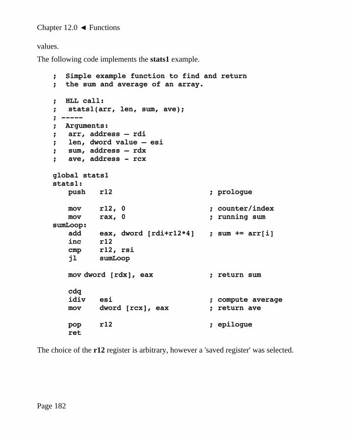
Chapter 12.0 ◄ Functions
values.
The following code implements the stats1 example.
; Simple example function to find and return; the sum and average of an array.
; HLL call:; stats1(arr, len, sum, ave);; -----; Arguments:; arr, address – rdi; len, dword value – esi; sum, address – rdx; ave, address - rcx
global stats1stats1:
push r12 ; prologue
mov r12, 0 ; counter/indexmov rax, 0 ; running sum
sumLoop:add eax, dword [rdi+r12*4] ; sum += arr[i]inc r12cmp r12, rsijl sumLoop
mov dword [rdx], eax ; return sum
cdqidiv esi ; compute averagemov dword [rcx], eax ; return ave
pop r12 ; epilogueret
The choice of the r12 register is arbitrary, however a 'saved register' was selected.
Page 182

Chapter 12.0 ► Functions
The call frame for this function would be as follows:
...
rip (return address)
r12 ← rsp
...
The minimal use of the stack helps reduce the function call run-time overhead.
12.10 Example, Statistical Function2 (non-leaf)
This extended example will demonstrate calling a simple void function to find theminimum, median, maximum, sum and average of an array of numbers. The High-Level Language (HLL) call for C/C++ is as follows:
stats2(arr, len, min, med1, med2, max, sum, ave);
For this example, it is assumed that the array is sorted as ascending order. Additionally,for this example, the median will be the middle value. For an even length list, there aretwo middle values, med1 and med2, both of which are returned. For an odd length list,the single middle value is returned in both med1 and med2.
As per the C/C++ convention, the array, arr, is call-by-reference and the length, len, iscall-by-value. The arguments for min, med1, med2, max, sum, and ave are all call-by-reference (since there are no values as yet). For this example, the array arr, min, med1,med2, max, sum, and ave variables are all signed double-word integers. Of course, incontext, the len must be unsigned.
12.10.1 Caller
In this case, there are 8 arguments and only the first six can be passed in registers. Thelast two arguments are passed on the stack. The assembly language code in the callingroutine for the call to the stats function would be as follows:
; stats2(arr, len, min, med1, med2, max, sum, ave);push ave ; 8th arg, add of avepush sum ; 7th arg, add of summov r9, max ; 6th arg, add of maxmov r8, med2 ; 5th arg, add of med2mov rcx, med1 ; 4th arg, add of med1
Page 183

Chapter 12.0 ◄ Functions
mov rdx, min ; 3rd arg, addr of minmov esi, dword [len] ; 2nd arg, value of lenmov rdi, arr ; 1st arg, addr of arrcall stats2add rsp, 16 ; clear passed arguments
The 7th and 8th arguments are passed on the stack and pushed in reverse order inaccordance with the standard calling convention. After the function is completed, thearguments are cleared from the stack by adjusting the stack point register (rsp). Sincetwo arguments, 8 bytes each, were passed on the stack, 16 is added to the stack pointer.
Note, the setting of the esi register also sets the upper order double-word to zero, thusensuring the rsi register is set appropriately for this specific usage since length isunsigned.
No return value is provided by this void routine. If the function was a value returningfunction, the value returned would be in the A register.
12.10.2 Callee
The function being called, the callee, must perform the prologue and epilogue operations(as specified by the standard calling convention). Of course, function must perform thesummation of values in the array, find the minimum, medians, and maximum, computethe average, return all the values.
When call-by-reference arguments are passed on the stack, two steps are required toreturn the value.
• Get the address from the stack.
• Use that address to return the value.
A common error is to attempt to return a value to a stack based location in a single step,which will not change the referenced variable. For example, assuming the double-wordvalue to be returned is in the eax register and the 7th argument is call-by-reference andwhere the eax value is to be returned, the appropriate code would be as follows:
mov r12, qword [rbp+16]mov dword [r12], eax
These steps can not be combined into a single step. The following code
mov dword [rbp+16], eax
Page 184

Chapter 12.0 ► Functions
Would overwrite the address passed on the stack and not change the reference variable.
The following code implements the stats2 example.
; Simple example function to find and return; the sum and average of an array.; -----; HLL call:; stats2(arr, len, min, med1, med2, max, sum, ave);
; Arguments:; arr, address – rdi; len, dword value – esi; min, address – rdx; med1, address - rcx; med2, address - r8; max, address - r9; sum, address – stack (rbp+16); ave, address – stack (rbp+24)
global stats2stats2:
push rbp ; prologuemov rbp, rsppush r12
; -----; Get min and max.
mov eax, dword [rdi] ; get minmov dword [rdx], eax ; return min
mov r12, rsi ; get lendec r12 ; set len-1mov eax, dword [rdi+r12*4] ; get maxmov dword [r9], eax ; return max
; -----; Get medians
mov rax, rsimov rdx, 0
Page 185

Chapter 12.0 ◄ Functions
mov r12, 2div r12 ; rax = length/2
cmp rdx, 0 ; even/odd length?je evenLength
mov r12d, dword [rdi+rax*4] ; get arr[len/2]mov dword [rcx], r12d ; return med1mov dword [r8], r12d ; return med3jmp medDone
evenLength:mov r12d, dword [rdi+rax*4] ; get arr[len/2]mov dword [r8], r12d ; return med2dec raxmov r12d, dword [rdi+rax*4] ; get arr[len/2-1]mov dword [rcx], r12d ; return med1
medDone:
; -----; Find sum
mov r12, 0 ; counter/indexmov rax, 0 ; running sum
sumLoop:add eax, dword [rdi+r12*4] ; sum += arr[i]inc r12cmp r12, rsijl sumLoop
mov r12, qword [rbp+16] ; get sum addrmov dword [r12], eax ; return sum
; -----; Calculate average.
cdqidiv rsi ; average = sum/lenmov r12, qword [rbp+24] ; get ave addrmov dword [r12], eax ; return ave
Page 186

Chapter 12.0 ► Functions
pop r12 ; epiloguepop rbpret
The choice of the registers is arbitrary with the bounds of the calling convention.
The call frame for this function would be as follows:
...
<8th Argument> ← rbp + 24
<7th Argument> ← rbp + 16
rip (return address)
rbp ← rbp
rbx
r12 ← rsp
. . .
The preserved registers, rbx and r12 in this example, are pushed in arbitrary order.However, when popped, they must be popped in the exact reverse order as required tocorrectly restore their original values.
12.11 Stack-Based Local Variables
If local variables are required, they are allocated on the stack. By adjusting the rspregister, additional memory is allocated on the stack for locals. As such, when thefunction is completed, the memory used for the stack based local variables is released(and no longer use memory).
Further expanding the previous example, if we assume all array values are between 0and 99, and we wish to find the mode (number that occurs the most often), a singledouble-word variable count and a one hundred (100) element local double-word array,tmpArr[100] might be used.
As before, the frame register, rbp, is pushed on the stack and set pointing to itself. Theframe register plus an appropriate offset will allow accessing any arguments passed onthe stack. For example, rbp+16 is the location of the first stack-based argument (7th
integer argument).
Page 187

Chapter 12.0 ◄ Functions
After the frame register is pushed an adjustment to the stack pointer register, rsp, ismade to allocate space for the local variables, a 100-element array in this example.Since the count variable is a one double-word, 4-bytes is needed. The temporary arrayis 100 double-word elements, 400 bytes is required. Thus, a total of 404 bytes isrequired. Since the stack is implemented growing downward in memory, the 404 bytesis subtracted from the stack pointer register.
Then any saved registers, rbx and r12 in this example, are pushed on the stack.
When leaving the function, the saved registers and then the locals must be cleared fromthe stack. The preferred method of doing this is to pop the saved registers and then topcopy the rbp register into the rsp register, thus ensuring the rsp register points to thecorrect place on the stack.
mov rsp, rbp
This is generally better than adding the offset back to the stack since allocated spacemay be altered as needed without also requiring adjustments to the epilogue code.
It should be clear that variables allocated in this manner are uninitialized. Should thefunction require the variables to be initialized, possibly to 0, such initializations must beexplicitly performed.
For this example, the call frame would be formatted as follows:
...
<value of len> ← rbp + 24
<addr of list> ← rbp + 16
rip (return address)
rbp ← rbp
tmpArr[99]
tmpArr[98]
. . .
. . .
tmpArr[1]
← rbp - 400 = tmpArr[0]
← rbp - 404 = count
Page 188
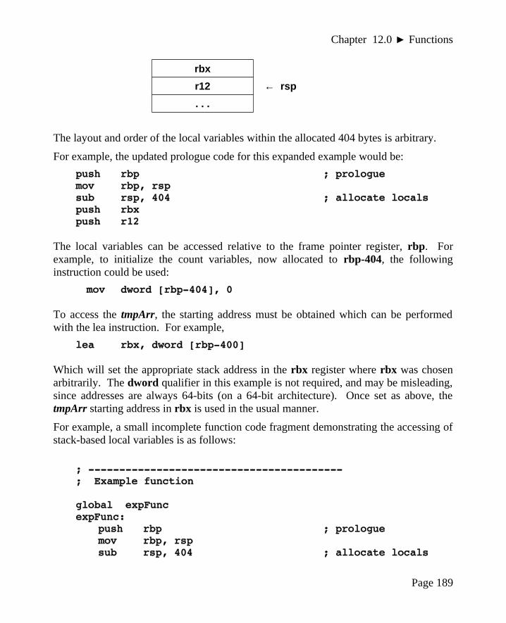
Chapter 12.0 ► Functions
rbx
r12 ← rsp
. . .
The layout and order of the local variables within the allocated 404 bytes is arbitrary.
For example, the updated prologue code for this expanded example would be:
push rbp ; prologuemov rbp, rspsub rsp, 404 ; allocate localspush rbxpush r12
The local variables can be accessed relative to the frame pointer register, rbp. Forexample, to initialize the count variables, now allocated to rbp-404, the followinginstruction could be used:
mov dword [rbp-404], 0
To access the tmpArr, the starting address must be obtained which can be performedwith the lea instruction. For example,
lea rbx, dword [rbp-400]
Which will set the appropriate stack address in the rbx register where rbx was chosenarbitrarily. The dword qualifier in this example is not required, and may be misleading,since addresses are always 64-bits (on a 64-bit architecture). Once set as above, thetmpArr starting address in rbx is used in the usual manner.
For example, a small incomplete function code fragment demonstrating the accessing ofstack-based local variables is as follows:
; -----------------------------------------; Example function
global expFuncexpFunc:
push rbp ; prologuemov rbp, rspsub rsp, 404 ; allocate locals
Page 189

Chapter 12.0 ◄ Functions
push rbxpush r12
; -----; Initialize count local variable to 0.
mov dword [rbp-404], 0
; -----; Increment count variable (for example)...
inc dword [rbp-404] ; count++
; -----; Loop to initialize tmpArr to all 0's.
lea rbx, dword [rbp-400] ; tmpArr addrmov r12, 0 ; index
zeroLoop:mov dword [rbx+r12*4], 0 ; tmpArr[index]=0inc r12cmp r12, 100jl zeroLoop
; -----; Done, restore all and return to calling routine.
pop r12 ; epiloguepop rbxmov rsp, rbp ; clear localspop rbpret
Note, this example function focuses only on how stack-based local variables areaccessed and does not perform anything useful.
12.12 Summary
This section presents a brief summary of the standard calling convention requirementswhich are as follows:
Page 190

Chapter 12.0 ► Functions
Caller Operations:
• The first six integer arguments are passed in registers
◦ rdi, rsi, rdx, rcx, r8, r9
• The 7th and on arguments are passed on the stack-based
◦ Pushes the arguments on the stack in reverse order (right to left, so that thefirst stack-based argument specified to the function is pushed last).
◦ Pushed arguments are passed as quadwords.
• The caller executes a call instruction to pass control to the function (callee).
• Stack-based arguments are cleared from the stack-based
◦ add rsp, <argCount*8>
Callee Operations:
• Function Prologue
◦ If arguments are passed on stack, the callee must save rbp to the stack andmove the value of rsp into rbp. This allows the callee to use rbp as a framepointer to access arguments on the stack in a uniform manner.
▪ The callee may then access its parameters relative to rbp. The quadwordat [rbp] holds the previous value of rbp as it was pushed; the nextquadword, at [rbp+8], holds the return address, pushed by the call. Theparameters start after that, at [rbp+16].
◦ If local variables are needed, the callee decreases rsp further to allocatespace on the stack for the local variables. The local variables are accessibleat negative offsets from rbp.
◦ The callee, if it wishes to return a value to the caller, should leave the valuein al, ax, eax, rax, depending on the size of the value being returned.
▪ A floating-point result is returned in xmm0.
◦ If altered, registers rbx, r12, 13, r14, r15 and rbp must be saved on thestack.
• Function Execution
◦ The function code is executed.
Page 191

Chapter 12.0 ◄ Functions
• Function Epilogue
◦ Restores any pushed registers.
◦ If local variables were used, the callee restores rsp from rbp to clear thestack-based local variables.
◦ The callee restores (i.e., pop's) the previous value of rbp.
◦ The call returns via ret instruction (return).
Refer to the sample functions to see specific examples of the calling convention.
12.13 Exercises
Below are some quiz questions and suggested projects based on this chapter.
12.13.1 Quiz Questions
Below are some quiz questions based on this chapter.
1) What are the two main actions of a function call?
2) What are the two instructions implement linkage?
3) When arguments are passed using values, it is referred to as?
4) When arguments are passed using addresses, it is referred to as?
5) If a function is called fifteen (15) times, how many times is the code placed inmemory by the assembler?
6) What happens during the execution of a call instruction (two things)?
7) According to the standard calling convention, as discussed in class, what is thepurpose of the initial pushes and final pop’s within most procedures?
8) If there are six (6) 64-bit integer arguments passed to a function, wherespecifically should each of the argument be passed?
9) If there are six (6) 32-bit integer arguments passed to a function, wherespecifically should each of the argument be passed?
10) What does it mean when a register is designated as temporary?
11) Name two temporary registers?
12) What is the name for the set of items placed on the stack as part of a functioncall?
Page 192

Chapter 12.0 ► Functions
13) What does it mean when a function is referred to as a leaf function?
14) What is the purpose of the add rsp, <immediate> after the callstatement?
15) If three arguments are passed on the stack, what is the value for the<immediate>?
16) If there are seven (7) arguments passed to a function, and the function itselfpushes the rbp, rbx, and r12 registers (in that order), what is the correct offsetof the stack-based argument when using the standard calling convention?
17) What, if any, is the limiting factor for how many times a function can be called?
18) If a function must return a result for the variable sum, how should the sumvariable be passed (call-by-reference or call-by-value)?
19) If there are eight (8) arguments passed to a function, and the function itselfpushes the rbp, rbx, and r12 registers (in that order), what are the correct offsetsfor each of the two stack-based arguments (7th and 8th) when using the standardcalling convention?
20) What is the advantage of using stack dynamic local variables (as opposed tousing all global variables)?
12.13.2 Suggested Projects
Below are some suggested projects based on this chapter.
1) Create a main and implement the stats1 example function. Use the debugger toexecute the program and display the final results. Create a debugger input file toshow the results.
2) Create a main and implement the stats2 example function. Use the debugger toexecute the program and display the final results. Create a debugger input file toshow the results.
Page 193

Chapter 12.0 ◄ Functions
3) Create a main program and a function that will sort a list of numbers inascending order. Use the following selection39 sort algorithm:
beginfor i = 0 to len-1
small = arr(i)index = ifor j = i to len-1
if ( arr(j) < small ) thensmall = arr(j)index = j
end_ifend_forarr(index) = arr(i)arr(i) = small
end_forend_begin
The main should call the function on at least three different data sets. Use thedebugger to execute the program and display the final results. Create a debuggerinput file to show the results.
4) Update the program from the previous question to add a stats function that findsthe minimum, median, maximum, sum, and average for the sorted list. The statsfunction should be called after the sort function to make the minimum andmaximum easier to find. Use the debugger to execute the program and displaythe final results. Create a debugger input file to show the results.
5) Update the program from the previous question to add an integer square rootfunction and a standard deviation function. To estimate the square root of anumber, use the following algorithm:
iSqrt est = iNumber
iSqrt est =(
iNumberiSqrt est )+ iSqrt est
2
iterate 50 times
39 For more information, refer to: http://en.wikipedia.org/wiki/Selection_sort
Page 194

Chapter 12.0 ► Functions
The formula for standard deviation is as follows:
iStandardDeviation = √ ∑i= 0
length−1
( list [ i ] − average)2
length
Note, perform the summation and division using integer values. Use thedebugger to execute the program and display the final results. Create a debuggerinput file to show the results.
6) Convert the integer to ASCII macro from the previous chapter into an voidfunction. The function should convert a signed integer into a right-justifiedstring of a given length. This will require including any leading blanks, a sign(“+” or “-”), the digits, and the NULL. The function should accept the value forthe integer and the address of where to place the NULL terminated string, andthe value of the maximum string length - in that order. Develop a main programto call the function on a series of different integers. The main should include theappropriate data declarations. Use the debugger to execute the program anddisplay the final results. Create a debugger input file to show the results.
7) Create a function to convert an ASCII string representing a number into aninteger. The function should read the string and perform appropriate errorchecking. If there is an error, the function should return FALSE (a definedconstant set to 0). If the string is valid, the function should convert the stringinto an integer. If the conversion is successful, the function should return TRUE(a defined constant set to 1). Develop a main program to call the function on aseries of different integers. The main should include the appropriate datadeclarations and applicable the constants. Use the debugger to execute theprogram and display the final results. Create a debugger input file to show theresults.
Page 195

Chapter 12.0 ◄ Functions
Page 196

13.0 System ServicesThere are many operations that an application program must use the operating system toperform. Such operations include console output, keyboard input, file services (open,read, write, close, etc.), obtaining the time or date, requesting memory allocation, andmany others.
Accessing system services is how the application requests that the operating systemperform some specific operation (on behalf of the process). More specifically, thesystem call is the interface between an executing process and the operating system.
This section provides an explanation of how to use some basic system service calls.More information on additional system service calls is located in Appendix C, SystemService Calls.
13.1 Calling System Services
A system service call is logically similar to calling a function, where the function codeis located within the operating system. The function may require privileges to operatewhich is why control must be transferred to the operating system.
When calling system services, arguments are placed in the standard argument registers.System services do not typically use stack-based arguments. This limits the argumentsof a system services to six (6), which does not present a significant limitation.
To call a system service, the first step is to determine which system service is desired.There are many system services (see Appendix C). The general process is that thesystem service call code is placed in the rax register. The call code is a number that hasbeen assigned for the specific system service being requested. These are assigned aspart of the operating system and can not be changed by application programs. Tosimplify the process, this text will define a very small subset of system service callcodes to a set of constants. For this text, and the associated examples, the subset of
Page 197
Chapter13
Linux is basically a simple operating system, but you have to be a genius to understand the simplicity.

Chapter 13.0 ◄ System Services
system call code constants are defined and shown in the source file to help providecomplete clarity for new assembly language programmers. For more experiencedprogrammers, typically developing larger or more complex programs, a complete list ofconstants is in a file and included into the source file.
If any are needed, the arguments for system services are placed in the rdi, rsi, rdx, r10,r8, and r9 registers (in that order). The following table shows the argument locationswhich are consistent with the standard calling convention.
Register Usage
rax Call code (see table)
rdi 1st argument (if needed)
rsi 2nd argument (if needed)
rdx 3rd argument (if needed)
r10 4th argument (if needed)
r8 5th argument (if needed)
r9 6th argument (if needed)
This is very similar to the standard calling convention for function calls, however the 4th
argument, if needed, uses the r10 register.
Each system call will use a different number of arguments (from none up to 6).However, the system service call code is always required.
After the call code and any arguments are set, the syscall instruction is executed. Thesyscall instruction will pause the current process and transfer control to the operatingsystem which will attempt to perform the service specified in the rax register. When thesystem service returns, the process will be resumed.
13.2 Newline Character
As a refresher, in the context of output, a newline means move the cursor to the start ofthe next line. The many languages, including C, it is often noted as “\n” as part of astring. C++ uses endl in the context of a cout statement. For example, “Hello World 1”and “Hello\nWorld 2” would be displayed as follows:
Hello World 1HelloWorld 2
Page 198

Chapter 13.0 ► System Services
Nothing is displayed for the newline, but the cursor is moved to the start of the next lineas shown.
In Unix/Linux systems, the linefeed, abbreviated LF with an ASCII value of 10 (or0x0A), is used as the newline character. In Windows systems, the newline is carriagereturn, abbreviated as CR with an ASCII value 13 (or 0x0D) followed by the LF. TheLF is used in the code examples in the text.
The reader may have seen instances where a text file is downloaded from a web pageand displayed using Windows Notepad where all the formatting is lost and to look likeall the text is one one very long line. This is typically due to a Unix/Linux formattedfile, which uses only LF's, being displayed with a Windows utility that expects CR/LFpairs and does not display correctly when only LF's are found. Other Windowssoftware, like Notepad++ (open source text editor) will recognize and handle thedifferent newline formats and display correctly.
13.3 Console Output
The system service to output characters to the console is the system write (SYS_write).Like a high level language characters are written to standard out (STDOUT) which isthe console. The STDOUT is the default file descriptor for the console. The filedescriptor is already opened and available for use in programs (assembly and high levellanguages).
The arguments for the write system service are as follows:
Register SYS_write
rax Call code = SYS_write (1)
rdi Output location, STDOUT (1)
rsi Address of characters to output.
rdx Number of characters to output.
Assuming the following declarations:
STDOUT equ 1 ; standard outputSYS_write equ 1 ; call code for write
msg db "Hello World"msgLen dq 11
Page 199

Chapter 13.0 ◄ System Services
For example to output “Hello World” (its traditional) to the console, the system write(SYS_write) would be used. The code would be as follows:
mov rax, SYS_writemov rdi, STDOUTmov rsi, msg ; msg addressmov rdx, qword [msgLen] ; length valuesyscall
Refer to the next section for a complete program to display the above message. Itshould be noted that the operating system does not check if the string is valid.
13.3.1 Example, Console Output
This example is a complete program to output some strings to the console. In thisexample, one string includes new line and the other does not.
; Example program to demonstrate console output.; This example will send some messages to the screen.
; **********************************************
section .data
; -----; Define standard constants.
LF equ 10 ; line feedNULL equ 0 ; end of stringTRUE equ 1FALSE equ 0
EXIT_SUCCESS equ 0 ; success code
STDIN equ 0 ; standard inputSTDOUT equ 1 ; standard outputSTDERR equ 2 ; standard error
SYS_read equ 0 ; readSYS_write equ 1 ; writeSYS_open equ 2 ; file openSYS_close equ 3 ; file closeSYS_fork equ 57 ; fork
Page 200

Chapter 13.0 ► System Services
SYS_exit equ 60 ; terminateSYS_creat equ 85 ; file open/createSYS_time equ 201 ; get time
; -----; Define some strings.
message1 db "Hello World.", LF, NULLmessage2 db "Enter Answer: ", NULLnewLine db LF, NULL
;------------------------------------------------------
section .textglobal _start_start:
; -----; Display first message.
mov rdi, message1call printString
; -----; Display second message message and then newline
mov rdi, message2call printString
mov rdi, newLinecall printString
; -----; Example program done.
exampleDone:mov rax, SYS_exitmov rdi, EXIT_SUCCESSsyscall
; ******************************************************; Generic function to display a string to the screen.
Page 201

Chapter 13.0 ◄ System Services
; String must be NULL terminated.; Algorithm:; Count characters in string (excluding NULL); Use syscall to output characters
; Arguments:; 1) address, string; Returns:; nothing
global printStringprintString:
push rbx
; -----; Count characters in string.
mov rbx, rdimov rdx, 0
strCountLoop:cmp byte [rbx], NULLje strCountDoneinc rdxinc rbxjmp strCountLoop
strCountDone:
cmp rdx, 0je prtDone
; -----; Call OS to output string.
mov rax, SYS_write ; system code for write()mov rsi, rdi ; address of char's to writemov rdi, STDOUT ; standard out
; RDX=count to write, set abovesyscall ; system call
; -----; String printed, return to calling routine.
Page 202

Chapter 13.0 ► System Services
prtDone:pop rbxret
The output would be as follows:
Hello World.Enter Answer:_
The newline (LF) was provided as part of the first string (message1) thus placing thecursor on the start of the next line. The second message would leave the cursor on thesame line which would be appropriate for reading input from the user (which is not partof this example). A final newline is printed since no actual input is obtained in thisexample.
The additional, unused constants are included for reference.
13.4 Console Input
The system service to read characters from the console is the system read (SYS_read).Like a high level language, for the console, characters are read from standard input(STDIN). The STDIN is the default file descriptor for reading characters from from thekeyboard. The file descriptor is already opened and available for use in program(assembly and high level languages).
Reading characters interactively from the keyboard presents an additional complication.When using the system service to read from the keyboard, much like the write systemservice, the number of characters to read is required. Of course, we will need to declarean appropriate amount of space to store the characters being read. If we request 10characters to read and the user types more than 10, the additional characters will be lost,which is not a significant problem. If the user types less than 10 characters, for example5 characters, all five characters will be read plus the newline (LF) for a total of sixcharacters.
A problem arises if input is redirected from a file. If we request 10 characters, and thereare 5 characters on the first line and more on the second line, we will get the sixcharacters from the first line (5 characters plus the newline) and the first four charactersfrom the next line for the total of 10. This is undesirable.
To address this, for interactively reading input, we will read one character at a time untila LF (the Enter key) is read. Each character will be read and then stored, one at a time,in an appropriately sized array.
Page 203

Chapter 13.0 ◄ System Services
The arguments for the read system service are as follows:
Register SYS_read
rax Call code = SYS_read (0)
rdi Output location, STDIN (0)
rsi Address of where to store characters read.
rdx Number of characters to read.
Assuming the following declarations:
STDIN equ 0 ; standard inputSYS_read equ 0 ; call code for read
inChar db 0
For example to read a single character from the keyboard, the system read (SYS_read)would be used. The code would be as follows:
mov rax, SYS_readmov rdi, STDINmov rsi, inChar ; msg addressmov rdx, 1 ; read countsyscall
Refer to the next section for a complete program to read characters from the keyboard.
13.4.1 Example, Console Input
The example is a complete program to read a line of 50 characters from the keyboard.Since space for the newline (LF) along with a final NULL termination is included, aninput array allowing 52 bytes would be required.
This example will read up to 50 characters from the user and then echo the input back tothe console to verify that the input was read correctly.
; Example program to demonstrate console output.; This example will send some messages to the screen.; **********************************************
section .data
Page 204

Chapter 13.0 ► System Services
; -----; Define standard constants.
LF equ 10 ; line feedNULL equ 0 ; end of string
TRUE equ 1FALSE equ 0
EXIT_SUCCESS equ 0 ; success code
STDIN equ 0 ; standard inputSTDOUT equ 1 ; standard outputSTDERR equ 2 ; standard error
SYS_read equ 0 ; readSYS_write equ 1 ; writeSYS_open equ 2 ; file openSYS_close equ 3 ; file closeSYS_fork equ 57 ; forkSYS_exit equ 60 ; terminateSYS_creat equ 85 ; file open/createSYS_time equ 201 ; get time
; -----; Define some strings.
STRLEN equ 50
pmpt db "Enter Text: ", NULLnewLine db LF, NULL
section .bsschr resb 1inLine resb STRLEN+2 ; total of 52
;------------------------------------------------------
section .textglobal _start_start:
Page 205

Chapter 13.0 ◄ System Services
; -----; Display prompt.
mov rdi, pmptcall printString
; -----; Read characters from user (one at a time)
mov rbx, inLine ; inLine addrmov r12, 0 ; char count
readCharacters:mov rax, SYS_read ; system code for readmov rdi, STDIN ; standard inlea rsi, byte [chr] ; address of chrmov rdx, 1 ; count (how many to read)syscall ; do syscall
mov al, byte [chr] ; get character just readcmp al, LF ; if linefeed, input doneje readDone
inc r12 ; count++cmp r12, STRLEN ; if # chars > STRLENjae readCharacters ; stop placing in buffer
mov byte [rbx], al ; inLine[i] = chrinc rbx ; update tmpStr addr
jmp readCharactersreadDone:
mov byte [rbx], NULL ; add NULL termination
; -----; Output the line to verify successful read
mov rdi, inLinecall printString
; -----; Example done.
Page 206

Chapter 13.0 ► System Services
exampleDone:mov rax, SYS_exitmov rdi, EXIT_SUCCESSsyscall
; ******************************************************; Generic procedure to display a string to the screen.; String must be NULL terminated.; Algorithm:; Count characters in string (excluding NULL); Use syscall to output characters
; Arguments:; 1) address, string; Returns:; nothing
global printStringprintString:
push rbx
; -----; Count characters in string.
mov rbx, rdimov rdx, 0
strCountLoop:cmp byte [rbx], NULLje strCountDoneinc rdxinc rbxjmp strCountLoop
strCountDone:
cmp rdx, 0je prtDone
; -----; Call OS to output string.
Page 207

Chapter 13.0 ◄ System Services
mov rax, SYS_write ; system code for write()mov rsi, rdi ; address of char's to writemov rdi, STDOUT ; standard out
; RDX=count to write, set abovesyscall ; system call
; -----; String printed, return to calling routine.
prtDone:pop rbxret
If we were to completely stop reading at 50 (STRLEN) characters and the user entersmore characters, the characters might cause input errors for successive read operations.To address any extra characters the user might enter, the extra characters are read fromthe keyboard but not placed in the input buffer (inLine above). This ensures that theextra input is removed from the input steam and but does not overrun the array.
The additional, unused constants are included for reference.
13.5 File Open Operations
In order to perform file operations such as read and write, the file must first be opened.There are two file open operations, open and open/create. Each of the two openoperations are explained in the following sections.
After the file is opened, in order to perform file read or write operations the operatingsystem needs detailed information about the file, including the complete status andcurrent read/write location. This is necessary to ensure that read or write operationspick up where they left off (from last time).
If the file open operation fails, an error code will be returned. If the file open operationsucceeds, a file descriptor is returned. This applies to both high level languages andassembly code.
The file descriptor is used by the operating system to access the complete informationabout the file. The complete set of information about an open file is stored in anoperating system data structure named File Control Block (FCB). In essence, the filedescriptor is used by the operating system to reference the correct FCB. It is theprogrammer's responsibility to ensure that the file descriptor is stored and use correctly.
Page 208

Chapter 13.0 ► System Services
13.5.1 File Open
The file open requires that the file exist in order to be opened. If the file does not exist,it is an error.
The file open operation also requires the parameter flag to specify the access mode. Theaccess mode must include one of the following:
• Read-Only Access → O_RDONLY
• Write-Only Access → O_WRONLY
• Read/Write Access → O_RDWR
One of these access modes must be used. Additional access modes may be used byOR'ing with one of these. This might include modes such as append mode (which is notaddressed in this text). Refer to Appendix C, System Services for additionalinformation regarding the file access modes.
The arguments for the file open system service are as follows:
Register SYS_open
rax Call code = SYS_open (2)
rdi Address of NULL terminated file name string
rsi File access mode flag
Assuming the following declarations:
SYS_open equ 2 ; file open
O_RDONLY equ 000000q ; read onlyO_WRONLY equ 000001q ; write onlyO_RDWR equ 000002q ; read and write
After the system call, the rax register will contain the return value. If the file openoperation fails, rax will contain a negative value (i.e., < 0). The specific negative valueprovides an indication of the type of error encountered. Refer to Appendix C, SystemServices for additional information on error codes. Typical errors might include invalidfile descriptor, file not found, or file permissions error.
If the file open operation succeeds, rax contains the file descriptor. The file descriptorwill be required for further file operations and should be saved.
Page 209

Chapter 13.0 ◄ System Services
Refer to the section on Example File Read for a complete example that opens a file.
13.5.2 File Open/Create
A file open/create operation will create a file. If the file does not exist, a new file willbe created. If the file already exists, it will be erased and a new file created. Thus, theprevious contents of the file will be lost.
A file access mode must be specified. Since the file is being created, the access modemust include the file permissions that will be set when the file is created. This wouldinclude specifying read, write, and/or execute permissions for the user, group, or worldas is typical for Linux file permissions. The only permissions addressed in this exampleare for the user or owner of the file. As such, others users (i.e., using other accounts)will not be able to access the file our program creates. Refer to Appendix C, SystemServices for additional information regarding the file access modes.
The arguments for the file open/create system service are as follows:
Register SYS_creat
rax Call code = SYS_creat (85)
rdi Address of NULL terminated file name string
rsi File access mode flag
Assuming the following declarations:
SYS_creat equ 85 ; file open
O_CREAT equ 0x40O_TRUNC equ 0x200O_APPEND equ 0x400
S_IRUSR equ 00400q ; owner, read permissionS_IWUSR equ 00200q ; owner, write permissionS_IXUSR equ 00100q ; owner, execute permission
The file status flags “S_IRUSR | S_IWUSR” would allow simultaneous read and write,which is typical. The “|” is a logical OR operation, thus combining the selections.
If the file open/create operation does not succeed, a negative value is returned in the raxregister. If file open/create operation succeeds, a file descriptor is returned. The file
Page 210

Chapter 13.0 ► System Services
descriptor is used for all subsequent file operations.
Refer to the section on Example File Write for a complete example file open/create.
13.6 File Read
A file must be opened with the appropriate file access flags before it can be read.
The arguments for the file read system service are as follows:
Register SYS_read
rax Call code = SYS_read (0)
rdi File descriptor (of open file)
rsi Address of where to place characters read
rdx Count of characters to read
Assuming the following declarations:
SYS_read equ 0 ; file read
If the file read operation does not succeed, a negative value is returned in the raxregister. If the file read operation succeeds, the number of characters actually read isreturned.
Refer to the next section on example file read for a complete file read example.
13.7 File Write
The arguments for the file write system service are as follows:
Register SYS_write
rax Call code = SYS_write (1)
rdi File descriptor (of open file)
rsi Address of where to place characters to write
rdx Count of characters to write
Assuming the following declarations:
SYS_write equ 1 ; file write
Page 211

Chapter 13.0 ◄ System Services
If the file write operation does not succeed, a negative value is returned in the raxregister. If the file write operation does succeed, the number of characters actuallywritten is returned.
Refer to the section on Example File Read for a compete file write example.
13.8 File Operations Examples
This section contains some simple example programs to demonstrate very basic file I/Ooperations. The more complex issues regarding file I/O buffering are addressed in asubsequent chapter.
13.8.1 Example, File Write
This example program writes a short message to a file. The file created contains asimple message, a URL in this example. The file name and message to be written to thefile are hard-coded. This helps simplify the example, but is not realistic.
Since the open/create service is used, the file will be created (even if an old version mustbe overwritten).
; Example program to demonstrate file I/O. This example; will open/create a file, write some information to the; file, and close the file. Note, the file name and; write message are hard-coded for the example.;--------------------------------------------------------
section .data
; -----; Define standard constants.
LF equ 10 ; line feedNULL equ 0 ; end of stringTRUE equ 1FALSE equ 0EXIT_SUCCESS equ 0 ; success codeSTDIN equ 0 ; standard inputSTDOUT equ 1 ; standard outputSTDERR equ 2 ; standard error
SYS_read equ 0 ; read
Page 212
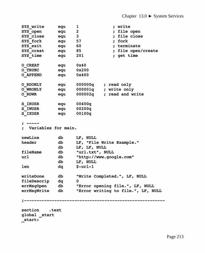
Chapter 13.0 ► System Services
SYS_write equ 1 ; writeSYS_open equ 2 ; file openSYS_close equ 3 ; file closeSYS_fork equ 57 ; forkSYS_exit equ 60 ; terminateSYS_creat equ 85 ; file open/createSYS_time equ 201 ; get time
O_CREAT equ 0x40O_TRUNC equ 0x200O_APPEND equ 0x400
O_RDONLY equ 000000q ; read onlyO_WRONLY equ 000001q ; write onlyO_RDWR equ 000002q ; read and write
S_IRUSR equ 00400qS_IWUSR equ 00200qS_IXUSR equ 00100q
; -----; Variables for main.
newLine db LF, NULLheader db LF, "File Write Example."
db LF, LF, NULLfileName db "url.txt", NULLurl db "http://www.google.com"
db LF, NULLlen dq $-url-1
writeDone db "Write Completed.", LF, NULL fileDescrip dq 0errMsgOpen db "Error opening file.", LF, NULLerrMsgWrite db "Error writing to file.", LF, NULL
;--------------------------------------------------------
section .textglobal _start_start:
Page 213

Chapter 13.0 ◄ System Services
; -----; Display header line...
mov rdi, headercall printString
; -----; Attempt to open file.; Use system service for file open
; System Service - Open/Create; rax = SYS_creat (file open/create); rdi = address of file name string; rsi = attributes (i.e., read only, etc.)
; Returns:; if error -> eax < 0; if success -> eax = file descriptor number
; The file descriptor points to the File Control; Block (FBC). The FCB is maintained by the OS.; The file descriptor is used for all subsequent; file operations (read, write, close).
openInputFile:mov rax, SYS_creat ; file open/createmov rdi, fileName ; file name stringmov rsi, S_IRUSR | S_IWUSR ; allow read/writesyscall ; call the kernel
cmp rax, 0 ; check for successjl errorOnOpen
mov qword [fileDescrip], rax ; save descriptor; -----; Write to file.; In this example, the characters to write are in a; predefined string containing a URL.
; System Service - write; rax = SYS_write; rdi = file descriptor
Page 214

Chapter 13.0 ► System Services
; rsi = address of characters to write; rdx = count of characters to write; Returns:; if error -> rax < 0; if success -> rax = count of characters actually read
mov rax, SYS_writemov rdi, qword [fileDescriptor]mov rsi, urlmov rdx, qword [len]syscall
cmp rax, 0jl errorOnWrite
mov rdi, writeDonecall printString
jmp exampleDone
; -----; Close the file.; System Service - close; rax = SYS_close; rdi = file descriptor
mov rax, SYS_closemov rdi, qword [fileDescriptor]syscall
jmp exampleDone
; -----; Error on open.; note, rax contains an error code which is not used; for this example.
errorOnOpen:mov rdi, errMsgOpencall printString
jmp exampleDone
Page 215

Chapter 13.0 ◄ System Services
; -----; Error on write.; note, eax contains an error code which is not used; for this example.
errorOnWrite:mov rdi, errMsgWritecall printString
jmp exampleDone
; -----; Example program done.
exampleDone:mov rax, SYS_exitmov rdi, EXIT_SUCCESSsyscall
; **********************************************************; Generic procedure to display a string to the screen.; String must be NULL terminated.; Algorithm:; Count characters in string (excluding NULL); Use syscall to output characters
; Arguments:; 1) address, string; Returns:; nothing
global printStringprintString:
push rbpmov rbp, rsppush rbx
; -----; Count characters in string.
mov rbx, rdi
Page 216

Chapter 13.0 ► System Services
mov rdx, 0strCountLoop:
cmp byte [rbx], NULLje strCountDoneinc rdxinc rbxjmp strCountLoop
strCountDone:cmp rdx, 0je prtDone
; -----; Call OS to output string.
mov eax, SYS_write ; code for write()mov rsi, rdi ; addr of charactersmov rdi, STDOUT ; file descriptor
; count set abovesyscall ; system call
; -----; String printed, return to calling routine.
prtDone:pop rbxpop rbpret
; *******************************************************
This example creates the file which is read by the next example.
13.8.2 Example, File Read
This example will read a file. The file to be read contains a simple message, the URLfrom the previous example. The file name is hard-coded which helps simplify theexample, but is not realistic. The file name used matches the previous file writeexample. If this example is executed prior to the write being executed, it will generatedan error since the file will not be found. After the file write example is executed, thisfile read example will read the file and display the contents.
Page 217

Chapter 13.0 ◄ System Services
; Example program to demonstrate file I/O.
; This example will open/create a file, write some; information to the file, and close the file.
; Note, the file name is hard-coded for this example.
; This example program will open a file, read the; contents, and write the contents to the screen.; This routine also provides some very simple examples; regarding handling various errors on system services.
; -------------------------------------------------------
section .data
; -----; Define standard constants.
LF equ 10 ; line feedNULL equ 0 ; end of string
TRUE equ 1FALSE equ 0EXIT_SUCCESS equ 0 ; success codeSTDIN equ 0 ; standard inputSTDOUT equ 1 ; standard outputSTDERR equ 2 ; standard error
SYS_read equ 0 ; readSYS_write equ 1 ; writeSYS_open equ 2 ; file openSYS_close equ 3 ; file closSYS_fork equ 57 ; forkSYS_exit equ 60 ; terminateSYS_creat equ 85 ; file open/createSYS_time equ 201 ; get time
O_CREAT equ 0x40O_TRUNC equ 0x200O_APPEND equ 0x400
Page 218

Chapter 13.0 ► System Services
O_RDONLY equ 000000q ; read onlyO_WRONLY equ 000001q ; write onlyO_RDWR equ 000002q ; read and write
S_IRUSR equ 00400qS_IWUSR equ 00200qS_IXUSR equ 00100q
; -----; Variables/constants for main.
BUFF_SIZE equ 255
newLine db LF, NULL header db LF, "File Read Example."
db LF, LF, NULL
fileName db "url.txt", NULL fileDescrip dq 0
errMsgOpen db "Error opening the file.", LF, NULL errMsgRead db "Error reading from the file.", LF, NULL
; -------------------------------------------------------
section .bssreadBuffer resb BUFF_SIZE
; -------------------------------------------------------
section .text global _start _start:
; ----- ; Display header line...
mov rdi, header call printString
; ----- ; Attempt to open file - Use system service for file open
Page 219

Chapter 13.0 ◄ System Services
; System Service - Open ; rax = SYS_open ; rdi = address of file name string ; rsi = attributes (i.e., read only, etc.) ; Returns: ; if error -> eax < 0 ; if success -> eax = file descriptor number
; The file descriptor points to the File Control; Block (FCB). The FCB is maintained by the OS. ; The file descriptor is used for all subsequent file ; operations (read, write, close).
openInputFile: mov rax, SYS_open ; file open mov rdi, fileName ; file name stringmov rsi, O_RDONLY ; read only access syscall ; call the kernel
cmp rax, 0 ; check for successjl errorOnOpen
mov qword [fileDescrip], rax ; save descriptor
; -----; Read from file.; For this example, we know that the file has only 1 line.
; System Service - Read; rax = SYS_read; rdi = file descriptor; rsi = address of where to place data; rdx = count of characters to read; Returns:; if error -> rax < 0; if success -> rax = count of characters actually read
mov rax, SYS_readmov rdi, qword [fileDescrip]mov rsi, readBuffermov rdx, BUFF_SIZE
Page 220

Chapter 13.0 ► System Services
syscall
cmp rax, 0jl errorOnRead
; -----; Print the buffer.; add the NULL for the print string
mov rsi, readBuffermov byte [rsi+rax], NULL
mov rdi, readBuffercall printString
printNewLine
; -----; Close the file.; System Service - close; rax = SYS_close; rdi = file descriptor
mov rax, SYS_closemov rdi, qword [fileDescriptor]syscall
jmp exampleDone
; -----; Error on open.; note, eax contains an error code which is not used; for this example.
errorOnOpen:mov rdi, errMsgOpencall printString
jmp exampleDone
; -----; Error on read.
Page 221

Chapter 13.0 ◄ System Services
; note, eax contains an error code which is not used; for this example.
errorOnRead:mov rdi, errMsgReadcall printString
jmp exampleDone
; -----; Example program done.
exampleDone:mov rax, SYS_exitmov rdi, EXIT_SUCCESSsyscall
; **********************************************************; Generic procedure to display a string to the screen.; String must be NULL terminated.; Algorithm:; Count characters in string (excluding NULL); Use syscall to output characters
; Arguments:; 1) address, string; Returns:; nothing
global printStringprintString:
push rbpmov rbp, rsppush rbx
; -----; Count characters in string.
mov rbx, rdimov rdx, 0
strCountLoop:cmp byte [rbx], NULL
Page 222

Chapter 13.0 ► System Services
je strCountDoneinc rdxinc rbxjmp strCountLoop
strCountDone:
cmp rdx, 0je prtDone
; -----; Call OS to output string.
mov eax, SYS_write ; code for write()mov rsi, rdi ; addr of charactersmov rdi, STDOUT ; file descriptor
; count set abovesyscall ; system call
; -----; String printed, return to calling routine.
prtDone:pop rbxpop rbpret
The printString() function is the exact same in both examples and is only repeated toallow each program to be assembled and executed independently.
13.9 Exercises
Below are some quiz questions and suggested projects based on this chapter.
13.9.1 Quiz Questions
Below are some quiz questions based on this chapter.
1) When using a system service, where is the call code placed?
2) Where is the code located when the syscall instruction is executed?
3) What is the call code and required arguments for a system service call to performconsole output?
Page 223

Chapter 13.0 ◄ System Services
4) Why was only one character read for interactive keyboard input?
5) What is returned for a successful file open system service call?
6) What is returned for an unsuccessful file open system service call?
7) If a system service call requires six (6) arguments, where specifically shouldthey be passed?
13.9.2 Suggested Projects
Below are some suggested projects based on this chapter.
1) Implement the printString() example void function and a simple main to test of aseries of strings. Use the debugger to execute the program and display the finalresults. Execute the program without the debugger and verify the appropriateoutput is displayed to the console.
2) Convert the example program to read input from keyboard into a readString()function. The function should accept arguments for the string address andmaximum string length (in that order). The maximum length should includespace for the NULL (an extra byte), which means the function must not allowmore than the maximum minus one characters to be stored in the string. Ifadditional characters are entered by the user, they should be cleared from theinput stream, but not stored. The function should not include the newline in thereturned string. The function should return the number of characters in the stringnot including the NULL. The printString() function from the previous problemshould be used unchanged. When done, create an appropriate main to test thefunction. Use the debugger as necessary to debug the program. When workingcorrectly, execute the program from the command line which will display thefinal results to the console.
3) Based on the file write example, create a value returning fileWrite() function towrite a password to a file. The function should arguments for the address of thefile name and the address of the NULL terminated password string. The fileshould be created, opened, the password string written to the file, and the fileclosed. The function should return SUCCESS if the operations worked correctlyor NOSUCCESS if there is a problem. Problems might include not being able tocreate the file or not being able to write to the file. Create an appropriate main totest the function. Use the debugger as necessary to debug the program. Whenworking correctly, execute the program from the command line which willdisplay the final results to the console.
Page 224

Chapter 13.0 ► System Services
4) Based on the file read example, create a value returning fileRead() function toread a password from a file. The function should accept arguments for theaddress of file name, the address of where the store the password string, themaximum length of the password string, and the address of where to store thepassword length. The function should open the file, read a string representing apassword, close the file, and return the number of characters in the password.The maximum length should include space for the NULL, which means thefunction read must not store more than the maximum minus one characters in thestring. The function should return SUCCESS if the operations worked correctlyor NOSUCCESS if there is a problem. Problems might include the file notexisting or other read errors. Create an appropriate main to test the function.Use the debugger as necessary to debug the program. When working correctly,execute the program from the command line which will display the final resultsto the console.
Page 225

Chapter 13.0 ◄ System Services
Page 226

14.0 Multiple Source FilesAs a program grows in size and complexity, it is common that different parts of theprogram are stored in different source files. This allows a programmer to ensure thesource files do not become unreasonable large and would also allow multipleprogrammers to more easily work on different parts of the program.
The function calls, even those written by different programmers, will work togethercorrectly due to the standard calling convention as outlined in Chapter 12, Functions.This is even true when interfacing with a high-level language.
This chapter will present a simple assembly language example to demonstrate how tocreate and use source code in multiple files. In addition, an example of how to interfacewith a C/C++ source file is provided.
14.1 Extern Statement
If a function is called from a source file and the function code is not located in thecurrent source file, the assembler will generate an error. The same applies to variableaccessed the are not located in the current file. In order to inform the assembler that thefunction code or variable is in another file, the extern statement is used. The syntax isas follows:
extern <symbolName>
The symbol name would be the name of the function or variable that is located in adifferent source file. In general, using global variables accessed across multiple files isconsidered poor programming practice and should be used sparingly (if at all). Data istypically passed between functions as arguments for the function call.
The examples in the text focus on using external functions only with no globallydeclared variables.
Page 227
Chapter14
My new computer is so fast, it executes an infinite loop in 6 seconds.

Chapter 14.0 ◄ Multiple Source Files
14.2 Example, Sum and Average
The following is a simple example of a main that calls an assembly language function,stats(), to compute the integer sum and integer average for a list of signed integers. Themain and the function are in different source files and are presented as an example ofhow multiple source files are used. The example itself is really too small to actuallyrequire multiple source files.
14.2.1 Assembly Main
The main is as follows:
; Simple example to call an external function.
; ----------------------------------------------------------; Data section
section .data
; -----; Define standard constants
LF equ 10 ; line feedNULL equ 0 ; end of string
TRUE equ 1FALSE equ 0
EXIT_SUCCESS equ 0 ; success code
; -----; Declare the data
lst1 dd 1, -2, 3, -4, 5dd 7, 9, 11
len1 dd 8
lst2 dd 2, -3, 4, -5, 6dd -7, 10, 12, 14, 16
len2 dd 10
Page 228

Chapter 14.0 ► Multiple Source Files
section .bsssum1 resd 1ave1 resd 1
sum2 resd 1ave2 resd 1
; ----------------------------------------------------------
extern stats
section.textglobal _start_start:
; ----; Call the function; HLL Call: stats(lst, len, &sum, &ave);
mov rdi, lst1 ; data set 1mov esi, dword [len1]mov rdx, sum1mov rcx, ave1call stats
mov rdi, lst2 ; data set 2mov esi, dword [len2]mov rdx, sum2mov rcx, ave2call stats
; -----; Example program done
exampleDone:mov rax, SYS_exitmov rdi, EXIT_SUCCESSsyscall
The above main can be assembled with the same assemble command as described in Chapter 5, Tool chain. The extern statement will ensure that the assembler does not generate errors.
Page 229

Chapter 14.0 ◄ Multiple Source Files
14.2.2 Function Source
The function, in a different source file is as follows:
; Simple example void function.
; **********************************************************; Data declarations; Note, none needed for this example.; If needed, they would be declared here as always.
section .data
; **********************************************************
section .text
; --------------------------------------------------; Function to find integer sum and integer average; for a passed list of signed integers.
; Call:; stats(lst, len, &sum, &ave);
; Arguments Passed:; 1) rdi - address of array; 2) rsi - length of passed array; 3) rdx - address of variable for sum; 4) rcx - address of variable for average
; Returns:; sum of integers (via reference); average of integers (via reference)
global statsstats:
push r12
; -----; Find and return sum.
mov r11, 0 ; i=0mov r12d, 0 ; sum=0
Page 230

Chapter 14.0 ► Multiple Source Files
sumLoop:mov eax, dword [rdi+r11*4] ; get lst[i]add r12d, eax ; update suminc r11 ; i++cmp r11, rsijb sumLoop
mov dword [rdx], r12d ; return sum
; -----; Find and return average.
mov eax, r12dcdqidiv esi
mov dword [rcx], eax ; return average
; -----; Done, return to calling function.
pop r12ret
The above source file can be assembled with the same assemble command as described in Chapter 5, Tool chain. No extern statement is required since no external functions are called.
14.2.3 Assemble and Link
Assuming the main source file is named main.asm and the functions source file isnamed stats.asm, the following command will perform the assemble and link.
yasm -g dwarf2 -f elf64 main.asm -l main.lstyasm -g dwarf2 -f elf64 stats.asm -l stats.lstld -g -o main main.o stats.o
The files names can be changed as desired.
As usual, the debugger is started with the ddd <executable> command. It wouldbe appropriate to noted that using the debugger step command will step into the
Page 231

Chapter 14.0 ◄ Multiple Source Files
function, including showing the function source code (even if the source is in a differentfile). The debugger next command will execute the entire function and not show thesource. If the function is working, the next command would be most useful. In order todebug the function, the step command would be most useful.
If the “-g” option is omitted, the debugger will not be able to display the source code.
14.3 Interfacing with a High-Level Language
This section provides information on how a high-level language can call an assemblylanguage function and how an assembly language function can call a high-levellanguage function. This chapter presents examples for both.
In brief, the answer of how this is accomplished is through the standard callingconvention. As such, no additional or special code is needed when interfacing with ahigh-level language. The compiler or assembler will need to be informed about theexternal routines in order to avoid error messages about not being able to find the sourcecode for the non-local routines.
The general process for linking for multiple files was described in Chapter 5, ToolChain. The process of using multiple source files was described in Chapter 14, MultipleSource Files. It does not matter if the object files are from a high-level language or froman assembly language source.
14.3.1 Example, C++ Main / Assembly Function
When calling any functions that are in a separate source file, the compiler must beinformed that the function or functions source code are external to the current sourcefile. This is performed with an extern statement in C or C++. Other languages willhave a similar syntax. For a high-level language, the extern statement will include thefunction prototype which will allow the compiler to verify the function parameters andassociated types.
The following is a simple example using a C++ main with an assembly languagefunction.
#include <iostream>using namespace std;extern "C" void stats(int[], int, int *, int *);
int main(){
Page 232

Chapter 14.0 ► Multiple Source Files
int lst[] = {1, -2, 3, -4, 5, 7, 9, 11};int len = 8;int sum, ave;
stats(lst, len, &sum, &ave);
cout << "Stats:" << endl;cout << " Sum = " << sum << endl;cout << " Ave = " << ave << endl;
return 0;}
At this point, the compiler does not know the external function is written in assembly(nor does it matter).
The C compiler is pre-installed on Ubuntu. However, the C++ compiler is not installedby default.
A C version of the same program is also presented for completeness.
#include<stdio.h>extern void stats(int[], int, int *, int *);
int main(){
int lst[] = {1, -2, 3, -4, 5, 7, 9, 11};int len = 8;int sum, ave;
stats(lst, len, &sum, &ave);
printf ("Stats:\n");printf (" Sum = %d \n", sum);printf (" Ave = %d \n", ave);
return 0;}
The stats() function referenced here should be used unchanged from the previousexample.
Page 233

Chapter 14.0 ◄ Multiple Source Files
14.3.2 Compile, Assemble, and Link
As noted in the Functions Chapter, the C++ compiler should be used. For example,assuming that the C++ main is named main.cpp, and the assembly source file is namedstats.asm, the commands to compile, assemble, link, and execute as follows:
g++ -g -Wall -c main.cppyasm -g dwarf2 -f elf64 stats.asm -l stats.lstg++ -g -o main main.o stats.o
The file names can be changed as desired. Upon execution, the output would be asfollows:
./mainStats: Sum = 30 Ave = 3
If a C main is used, and assuming that the C main is named main.c, and the assemblysource file is named stats.asm, the commands to compile, assemble, link, and execute asfollows:
gcc -g -Wall -c main.cyasm -g dwarf2 -f elf64 stats.asm -l stats.lstgcc -g -o main main.o stats.o
The C compiler, gcc, or the C++ compiler, g++, is used to perform the linking as it isaware of the appropriate locations for the various C/C++ libraries.
14.4 Exercises
Below are some quiz questions and suggested projects based on this chapter.
14.4.1 Quiz Questions
Below are some quiz questions based on this chapter.
1) What is the statement to declare the functions, func1() and func2(), as externalassuming no arguments are needed for either function?
2) What is the statement to declare the functions, func1() and func2(), as external iftwo integer arguments are used for each function?
3) What will happen if an external function is called but is not declared as external.
Page 234

Chapter 14.0 ► Multiple Source Files
4) If an externally declared function is called but the programmer did not actuallywrite the function, when would the error be flagged, assemble time, link time, orrun time?
5) If an externally declared function is called but the programmer did not actuallywrite the function, what might the error be?
6) If the “-g” option is omitted from the assemble and link commands, would theprogram be able to execute?
14.4.2 Suggested Projects
Below are some suggested projects based on this chapter.
1) Implement the assembly language example program to find the sum and averagefor a list of signed integers. Ensure that the main and function are in differentsource files. Use the debugger to execute the program and display the finalresults.
2) Based on the example function stats(), split it into two value returning functions,lstSum() and lstAverage(). As noted in Chapter 12, Functions, value returningfunctions return their result in the A register. Since these are double-words, theresult will be returned in eax. Ensure that the main and both functions are in twodifferent source files. The two functions can be in the same source file. Use thedebugger to execute the program and display the final results.
3) Extend the previous exercise to display the sum and average to the console. TheprintString() example function (from multiple previous examples) should beplaced in a third source file (which can be used on other exercises). This projectwill require a function to convert an integer to ASCII (as outlined in Chapter 10).Use the debugger as needed to debug the program. When working, execute theprogram without the debugger and verify that the correct results are displayed tothe console.
4) Implement one of the C/C++ example main programs (either one). Additionallyimplement the assembly language stats() function example. Develop a simplebash script to perform the compile, assemble, and link. The link should beperformed with the applicable C/C++ compiler. Use the debugger as needed todebug the program. When working, execute the program without the debuggerand verify that the correct results are displayed to the console.
Page 235

Chapter 14.0 ◄ Multiple Source Files
Page 236

15.0 Stack Buffer OverflowA stack buffer overflow40 can occur when a program overflows a stack-based dynamicvariable (as described in Chapter 12.9, Stack-Based Local Variables). For example, if aprogram allocates and uses a stack-based local array holding 50 elements and more than50 elements are stored in the array, an overflow occurs. Such overflows are generallybad and typically cause program bugs and possibly even crash the program. The stackwill contain other important information such as other variables, persevered registers,frame point, return address, and/or stack-based parameters. If such data is over-written,it will likely cause problems which can be very difficult to debug since the symptomwill likely be unrelated to where the problem actually occurs.
If a stack buffer overflow is caused deliberately as part of an attack it is referred to asstack smashing. Due to the standard calling convention, the layout of the stack-basedcall frame or activation record is fairly predictable. Such a stack buffer overflow can beby a malicious individual to inject executable code into the currently running program toperform some inappropriate actions. Under the right circumstances, such code injectioncould allow a black-hat41 hacker to perform unwanted actions potentially taking over thesystem.
The process of how a stack buffer overflow occurs and how it can be exploited areprovided in this chapter. This is presented in order to allow developers to clearlyunderstand the problem and thus learn how to protect themselves against suchvulnerabilities. The reader must be familiar with the details of the standard callingconvention as outlined in Chapter 12, Functions.
It should be noted that the stack buffer overflow problem exists in high-level languages.Working in assembly languages makes it easier to more clearly see and understand thedetails.
40 For more information, refer to: http://en.wikipedia.org/wiki/Stack_buffer_overflow41 For more information, refer to: http://en.wikipedia.org/wiki/Black_hat
Page 237
Chapter15
My new computer is so fast it requires two HALT instructions to stop it.

Chapter 15.0 ◄ Stack Buffer Overflow
15.1 Understanding a Stack Buffer Overflow
When a program calls a function, the standard calling convention provides the guidancefor how the parameters are passed, how the return address is saved, how and whichregisters must be preserved, and how stack-based local variables are to be allocated.
For example, consider the function call;
expFunc(arg1, arg2, arg3);
In addition, we will assume that the function, expFunc(), reads in a line of text from theuser and stores it in a locally declared array. The local variables include the array of 48bytes and one quadword local variable (8 bytes). This can be accomplished easily in ahigh level language or as is done in Chapter 13, System Services, Console Input.
The resulting call frame would be as follows:
Page 238
. . .
rip ← return address
rbp ← preserved base pointer
← Local array (48 bytes)
← Local quad variable (8 bytes)
rbx ← preserved saved register
r12 ← preserved saved register
r13 ← preserved saved register
. . .
Illustration 25: Stack Call Frame Example

Chapter 15.0 ► Stack Buffer Overflow
When the function completes, all elements of the call frame are removed. The preservedregisters are restored to their original contents, the local variables are removed, and thereturn address is copied off the stack and placed in the rip register which effects a jumpback to the original calling routine. As noted in Chapter 12, Functions, this layoutsupports multiple levels of function calls including recursion.
The example in Chapter 13 that reads characters from the user and entered them into anarray explicitly checked the character count to ensure that the count does not exceed thebuffer size. It would be easy to forget to perform this important check. Indeed, some Cfunctions such as strcpy() do not perform verification of sizes and are thus consideredunsafe42 or described as an unsafe function.
In this example, overwriting the 48 character buffer will destroy the contents of thestack that contain the original values for the rpb register and possibly the rip register. Ifthe stack contents of the original value of the rip register is altered or corrupted in anyway, the function will not be able to return to the calling routine and would attempt tojump to some random location. If the random location is outside the program scope,which is likely, the program will generate a segment fault (i.e., “seg fault” or programcrash).
Debugging this type of error can be a significant challenge. The error appears at thevery end of the function (on the return). The problem is actually in the body of thefunction and in fact may be due to code that is not included (as opposed to wrong codethat is there).
Testing if a program has this vulnerability would involve typing significantly morecharacters than expected when prompted. For example, if name is prompted for and 200characters are entered (possibly by holding down a key), the program crashing would bea sign that such a vulnerability exists. An error message would indicate such avulnerability does not exist. While straightforward, this type of testing is often notchecked thoroughly or even omitted entirely.
15.2 Code to Inject
Before discussing how the stack buffer overflow might be exploited, we will reviewwhat code might be injected. The code to be injected could be many things. We willassume the program is being executed in a controlled environment with no consoleaccess for the user. The lack of console access would limit what a user could do ideallyto only what the program allowed. This might be the case if the program is server-based
42 For more information, refer to: http://en.wikipedia.org/wiki/C_standard_library#Buffer_overflow_vulnerabilities
Page 239

Chapter 15.0 ◄ Stack Buffer Overflow
interacting with a user through a web or application front-end. The server would beprotected from direct user access for obvious security reasons.
As such, one possible attack vector might be to obtain console access to the back-endserver (where such access is normally not allowed).
There is a system service that can execute another program. Using this system service,exec, we could execute the sh program (shell) which is a standard Linux program. Thiswill create and open a shell providing console access. The newly created shell is limitedto the privileges of the process that started it. In a good security environment, theprocess will be granted only the privileges it requires. In a poor security environment,the process may have additional, unnecessary privilege which would make it easier foran unauthorized black-hat hacker to cause problems.
Given the following data declarations:
NULL equ 0progName db "/bin/sh", NULL
An example of the exec system service would be as follows:
; Example, system service call for exec.
mov rax, 59 mov rdi, progName syscall
A new console will appear. The reader is encouraged to try this code example and see itwork.
The list file for this code fragment would be as follows:
40 00000000 48C7C03B000000 mov rax, 5941 00000007 48C7C7[00000000] mov rdi, progName42 0000000E 0F05 syscall
Recall that the first column is the line number, the second column is relative address inthe code section and the third column is the machine language or the hex representationof the human readable instruction shown in the fourth column. The [00000000]represents the relative address of the string in the data section (progName in thisexample). It is zero since it is the first (and only) variable in the data section for thisexample.
Page 240

Chapter 15.0 ► Stack Buffer Overflow
If the machine language shown is entered into memory and executed, a shell or consolewould be opened. Getting the hex version of the code into memory can only beperformed via the keyboard (since there is no direct access to file system). This wouldbe done one character at a time. The 0x48 is the ASCII code for “0”, so “0” could beentered for that byte. However, the 0x0f and many of the other characters are moredifficult to enter directly as ASCII.
The command shell will allow entry of hex code in hex. By typing control key and theleft shift followed by a lower-case u and then four hex digits, the hex values can beentered one at a time. For example, to enter the 0x05, it would be;
CTRL SHIFT u 0 0 0 5
This can be done for most of the bytes except the 0x00. The 0x00 is a NULL which is anon-printable ASCII characters (used to mark string terminations). As such, the NULLcan not be entered from the keyboard. Additionally, the [00000000] address would notmake sense if the code is injected into another program.
To address these issues, we can re-write the example code and eliminate the NULL'sand change the address reference. The NULL's can be eliminated by using differentinstructions. For example, setting rax to 59 can be accomplished by xor'ing rax withitself and placing the 59 in al (having already ensured the upper 56 bits are 0 via thexor). The string can be placed on the stack and the current rsp used as the address of thestring. The string, “\bin\sh” is 7 bytes and the stack operation will require a push of 8bytes. Again, the NULL can not be entered and is not counted. An extra, unnecessary“/” can be added to the string which will not impact the operation providing exactly 8bytes in the string. Since the architecture is little-endian, in order to ensure that thestarting of the string is in low memory, it must be in the least significant byte of thepush. This will make the string appear backwards.
The revised program fragment would be as follows:
xor rax, rax ; clear raxpush rax ; place NULLs on stackmov rbx, 0x68732f6e69622f2f ; string -> "//bin/sh"push rbx ; put string in memorymov al, 59 ; call code in raxmov rdi, rsp ; rdi = addr of stringsyscall ; system call
Page 241

Chapter 15.0 ◄ Stack Buffer Overflow
The list file for the program fragment would be as follows:
52 00000013 4831C0 xor rax, rax 53 00000016 50 push rax 54 00000017 48BB2F2F62696E2F73 mov rbx, 0x68732f6e69622f2f 55 00000017 68 56 00000021 53 push rbx 57 00000022 B03B mov al, 59 58 00000024 4889E7 mov rdi, rsp 59 00000027 0F05 syscall
In this revised code there are no NULL's and the address reference is obtained from thestack pointer (rsp) which points to the correct string.
There is an assembly language instruction nop which performs no operation with amachine code of 0x90. In this example, the nop instruction is used simply to round outthe machine code to an even multiple of 8 bytes.
The series of hex values that would need to be entered is as follows:
0x48 0x31 0xC0 0x50 0x48 0xBB 0x2F 0x2F 0x62 0x69 0x6E 0x2F 0x73 0x68 0x53 0xB0 0x3B 0x48 0x89 0xE7 0x0F 0x05 0x90 0x90
While somewhat tedious, these characters can be entered by hand.
15.3 Code Injection
If the code to inject is available and can be entered, the next step would be actuallygetting the code executed.
Based on the previous example call frame, the code would be entered preceded by aseries of nop's (0x90). The exact spot where the rip is stored in the stack can bedetermined through trial and error. When the first byte of the 8 byte address is altered,the program will not be able to return to the calling routine and will likely crash. If thebytes of the rbp are corrupted, the program may fail in some way, but it will be differentthan the immediate crash caused by the corrupted rip. The code entered would beextended by 1 byte on each of many successive attempts. Finding this exact location inthis manner will take patience.
Once the rip location has been determined, the 8 bytes that are entered there will need tobe the address of where the injected code is in the stack where the user input was stored.This also would be determined through trial and error. However, the exact address of
Page 242
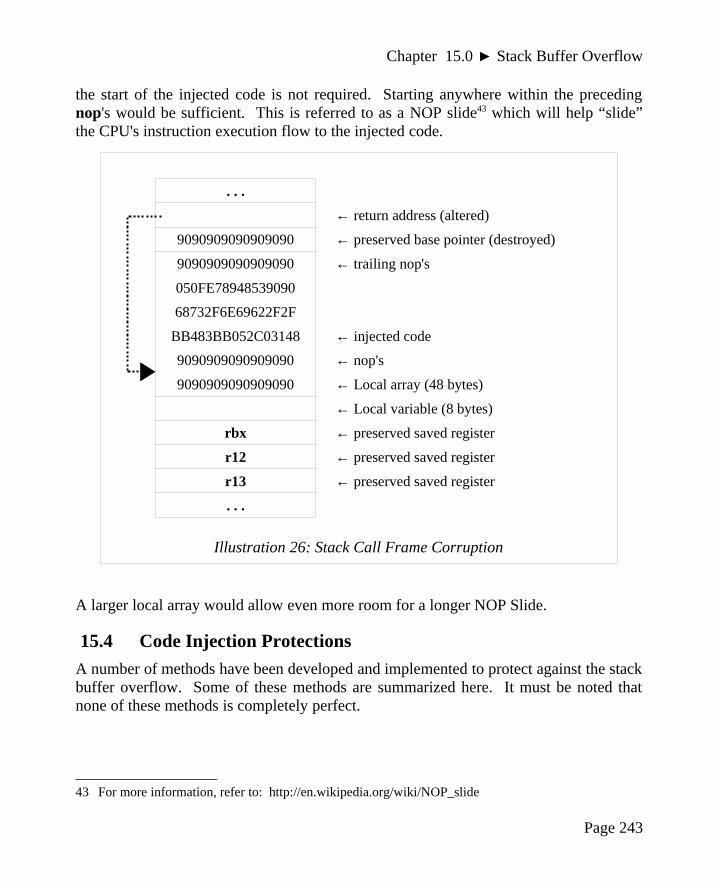
Chapter 15.0 ► Stack Buffer Overflow
the start of the injected code is not required. Starting anywhere within the precedingnop's would be sufficient. This is referred to as a NOP slide43 which will help “slide”the CPU's instruction execution flow to the injected code.
A larger local array would allow even more room for a longer NOP Slide.
15.4 Code Injection Protections
A number of methods have been developed and implemented to protect against the stackbuffer overflow. Some of these methods are summarized here. It must be noted thatnone of these methods is completely perfect.
43 For more information, refer to: http://en.wikipedia.org/wiki/NOP_slide
Page 243
. . .
← return address (altered)
9090909090909090 ← preserved base pointer (destroyed)
9090909090909090 ← trailing nop's
050FE78948539090
68732F6E69622F2F
BB483BB052C03148 ← injected code
9090909090909090 ← nop's
9090909090909090 ← Local array (48 bytes)
← Local variable (8 bytes)
rbx ← preserved saved register
r12 ← preserved saved register
r13 ← preserved saved register
. . .
Illustration 26: Stack Call Frame Corruption

Chapter 15.0 ◄ Stack Buffer Overflow
15.4.1 Data Stack Smashing Protector (or Canaries)
Data stack smashing protector, also referred to as stack canaries, is used to detect a stackbuffer overflow before execution of malicious code can occur. This works by placing ainteger, the value of which is randomly chosen at program start, in memory just beforethe return address (rip) in the call frame. In order to overwrite the return address, andthus execute the injected code, the canary value must also be overwritten. This canaryvalue is checked to make sure it has not changed before a routine pops the returnaddress.
For the GNU g++ compiler, this is option (-f-stack-protector) is enabled by default. Itcan be turned off with the -fno-stack-protector compiler option. Turning it off wouldbe necessary in order to perform testing using a C/C++ program of the injectiontechniques outlined in this chapter.
15.4.2 Data Execution Prevention
Data Execution Prevention44 (DEP) is a security feature that marks areas of memory aseither "executable" or "nonexecutable". Only code in a marked "executable" area isallowed to be executed. Code that is or injected into an area marked “nonexecutable”will not be allowed to execute. This helps prevent stack buffer overflow code injection.
15.4.3 Data Address Space Layout Randomization
Address space layout randomization (ASLR) is a technique to prevent an attacker fromreliably jumping to the injected code. ASLR randomly arranges the address spacepositions of key data areas of a process, including the base of the executable and thepositions of the stack, heap and libraries.
15.5 Exercises
Below are some quiz questions and suggested projects based on this chapter.
15.5.1 Quiz Questions
Below are some quiz questions based on this chapter.
1) When stack buffer overflow is caused deliberately as part of an attack it isreferred as what?
2) What does it mean when a C function is considered unsafe?
44 For more information, refer to: http://en.wikipedia.org/wiki/Data_Execution_Prevention
Page 244

Chapter 15.0 ► Stack Buffer Overflow
3) Is a program that reads user input still vulnerable if the input buffer issufficiently large (e.g., >1024 bytes)?
4) How might an attacker determine if an interactive program is vulnerable to abuffer overflow attack?
5) What is a “NOP slide”?
6) The text example injected code to open a new shell. Provide at least onedifferent idea for injected code that would cause problems.
7) Name three techniques designed to prevent stack buffer overflow attacks.
15.5.2 Suggested Projects
Below are some suggested projects based on this chapter.
1) Implement the second example program fragment to open a new shell. Use thedebugger to execute the program and display the final results. Execute theprogram without the debugger and verify that a new shell is opened.
2) Implement the console input program from Chapter 13. Remove the code for thebuffer size check. Execute the program without the debugger and ensure theappropriate input is read and that the output is displayed to the console. Verifythe entering too many characters will crash the program.
3) Using the program from the previous question and the program fragment to opena shell, attempt to inject the code into the running program. In order to savetime, print the value of the rsp at an appropriate location to allow the guessing ofthe target address significantly easier.
Page 245

Chapter 15.0 ◄ Stack Buffer Overflow
Page 246

16.0 Command Line ArgumentsThis chapter provides a summary of how the operating system handles command linearguments and how assembly language routines can access the arguments.
The term command line arguments is used to refer to the characters, if any, entered onthe command line after the program name. The command line arguments are often usedby programs to provide information or parameters to the program without the need forthe I/O associated with interactive prompting. Of course, if the parameters are notcorrect, the entire line must be re-entered.
Command line arguments were used by the assembler and linker to provide informationfor input files, output files, and various other options.
16.1 Parsing Command Line Arguments
The operating system is responsible for parsing, or reading, the command linearguments and deliver the information to the program. It is the responsibility of theprogram to determine what is considered correct and incorrect. When reading thecommand line, the operating system will consider an argument a set of non-spacecharacters (i.e., a string). The space or spaces between arguments is removed or ignoredby the operating system. In addition, the program name itself is considered the first, andpossibly only, argument. If other arguments are entered, at least one space is requiredbetween each argument.
All arguments are delivered to the program as character string, even numberinformation. If needed, the program must convert the character data into the numbervalue (float or integer) if needed.
For example, executing the program expProg with the following command linearguments:
./expProg one 42 three
Page 247
Chapter16
The code that is the hardest to debug is the code you know can't possibly be wrong.

Chapter 16.0 ◄ Command Line Arguments
will result four arguments as follows:
1. ./expProg2. one3. 424. three
The command line arguments are delivered to the program as parameters. As such, theprogram is like a function being called by the operating system. So, the standard callingconvention is used to convey the parameters.
16.2 High-Level Language Example
In general, it is assumed that the reader is already familiar with the basic C/C++command line handling. This section presents a brief summary of the how the C/C++language handles the delivery of command line information to the program.
The count of arguments is passed to the main program as the first integer parameter,typically called argc. The second parameter, typically called argv, is an array ofaddresses for each string associated with the corresponding argument.
For example, the following C++ example program will read the command linearguments and display them to the screen.
#include <iomanip>#include <iostream>using namespace std;
int main(int argc, char* argv[]){string bars;bars.append(50,'-');
cout << bars << endl;cout << "Command Line Arguments Example"
<< endl << endl;
cout << "Total arguments provided: " <<argc << endl;
cout << "The name used to start the program: "<< argv[0] << endl;
Page 248

Chapter 16.0 ► Command Line Arguments
if (argc > 1) {cout << endl << "The arguments are:" << endl;for (int n = 1; n < argc; n++)
cout << setw(2) << n << ": " <<argv[n] << endl;
}
cout << endl;cout << bars << endl;
return 0;}
Assuming the program is named argsExp, executing this program will produced thefollowing output:
./argsExp one 34 three--------------------------------------------------Command Line Arguments Example
Total arguments provided: 4The name used to start the program: ./args
The arguments are: 1: one 2: 34 3: three
--------------------------------------------------
It should be noted that the parameter '34' is a string. This example simply printed thestring to the console. If a parameter is to be used as a numeric value, the program mustconvert as required. This includes all error checking as necessary.
16.3 Argument Count and Argument Vector Table
Since the operating system will call the main program as a function, the standard callingconvention applies. The argument count and the argument vector address are passed asparameter in rdi and rsi in accordance with the standard calling convention. The firstargument, in rdi, is the integer argument count. The second argument, in rsi, is the
Page 249

Chapter 16.0 ◄ Command Line Arguments
argument vector table address.
The argument vector table is an array containing the quadword addresses of the stringfor each argument. Assuming the previous examples with 4 total arguments, the basicargument vector table layout is as follows:
Each string is NULL terminated by the operating system and will not contain a new linecharacter.
16.4 Assembly Language Example
An example assembly language program to read and display the command linearguments is included for reference. This example simply reads and displays thecommand line arguments.
; Command Line Arguments Example
; -------------------------------------------------------
section .data
Page 250
Table Contents C/C++ Reference
quadword address
of 4th argument argv[3]
quadword address
of 3rd argument argv[2]
quadword address
of 2nd argument argv[1]
argument vector (rsi) →
quadword address
of 1st argument argv[0]
Illustration 27: Argument Vector Layout

Chapter 16.0 ► Command Line Arguments
; -----; Define standard constants.
LF equ 10 ; line feedNULL equ 0 ; end of stringTRUE equ 1FALSE equ 0EXIT_SUCCESS equ 0 ; success code
STDIN equ 0 ; standard inputSTDOUT equ 1 ; standard outputSTDERR equ 2 ; standard error
SYS_read equ 0 ; readSYS_write equ 1 ; writeSYS_open equ 2 ; file openSYS_close equ 3 ; file closSYS_fork equ 57 ; forkSYS_exit equ 60 ; terminateSYS_creat equ 85 ; file open/createSYS_time equ 201 ; get time
; -----; Variables for main.
newLine db LF, NULL
; ------------------------------------------------------
section .textglobal mainmain:
; -----; Get command line arguments and echo to screen.; Based on the standard calling convention,; rdi = argc (argument count); rsi = argv (starting address of argument vector)
mov r12, rdi ; save for later use...mov r13, rsi
Page 251
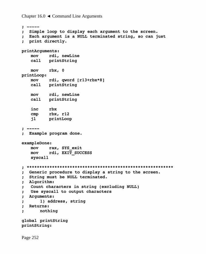
Chapter 16.0 ◄ Command Line Arguments
; -----; Simple loop to display each argument to the screen.; Each argument is a NULL terminated string, so can just; print directly.
printArguments:mov rdi, newLinecall printString
mov rbx, 0printLoop:
mov rdi, qword [r13+rbx*8]call printString
mov rdi, newLinecall printString
inc rbxcmp rbx, r12jl printLoop
; -----; Example program done.
exampleDone:mov rax, SYS_exitmov rdi, EXIT_SUCCESSsyscall
; **********************************************************; Generic procedure to display a string to the screen.; String must be NULL terminated.; Algorithm:; Count characters in string (excluding NULL); Use syscall to output characters; Arguments:; 1) address, string; Returns:; nothing
global printStringprintString:
Page 252

Chapter 16.0 ► Command Line Arguments
push rbpmov rbp, rsppush rbx
; -----; Count characters in string.
mov rbx, rdimov rdx, 0
strCountLoop:cmp byte [rbx], NULLje strCountDoneinc rdxinc rbxjmp strCountLoop
strCountDone:
cmp rdx, 0je prtDone
; -----; Call OS to output string.
mov eax, SYS_write ; code for write()mov rsi, rdi ; addr of charactersmov edi, STDOUT ; file descriptor
; count set abovesyscall ; system call
; -----; String printed, return to calling routine.
prtDone:pop rbxpop rbpret
; *******************************************************
The printString() function is repeated in this example and is unchanged from theprevious examples.
Page 253

Chapter 16.0 ◄ Command Line Arguments
It must be noted that in order for this to work, the program should be assembled as usualbut linked with the GNU C compiler, either GCC or G++. For example, assuming thisexample program is named cmdLine.asm, the assembly and linking would be as follows:
yasm -g dwarf2 -f elf64 cmdLine.asm -l cmdLine.lst gcc -g -o cmdLine cmdLine.o
If the standard linker is used, the arguments will not be passed in the correct manner.
16.5 Exercises
Below are some quiz questions and suggested projects based on this chapter.
16.5.1 Quiz Questions
Below are some quiz questions based on this chapter.
1) What software entity is responsible for parsing or reading the command linearguments?
2) What software entity is responsible verifying or checking the command linearguments?
3) What is the first command line argument?
4) Explain what argc and argv refer to.
5) In an assembly language program, where is argc passed to the program?
6) In an assembly language program, where is argv passed to the program?
7) If seven spaces are entered between each of the command line arguments, howare the spaces removed when the command line arguments are checked?
8) If a number is expected as a command line argument, and the user enters “12x3”(an invalid value), is an error generated by the operating system (i.e., theloader)?
Page 254

Chapter 16.0 ► Command Line Arguments
16.5.2 Suggested Projects
Below are some suggested projects based on this chapter.
1) Implement the example program to read and display the command linearguments. Use the debugger to execute the program and display the finalresults. Execute the program without the debugger and verify the appropriateoutput is displayed to the console.
2) Convert the command line example into a function that will display each of thecommand line arguments to the console. Use the debugger as necessary todebug the program. Execute the program without the debugger and verify theappropriate output is displayed to the console.
3) Create an assembly language program to accept a file name on the command lineand open the file and display the one line message contained in the file. A seriesof small text file should be created each containing one of the very importantmessages at the start of each chapter of this text. The program should performerror checking on the file name, and if valid, open the file. If the file openssuccessfully, the message should be read from the file displayed to the console.Appropriate error messages should be displayed if the file can not be opened orread. The program may assume that each message will be < 256 characters. Usethe debugger as necessary to debug the program. Execute the program withoutthe debugger and verify the appropriate output is displayed to the console.
4) Create an assembly language program the will accept three unsigned integernumbers from the command line, add the three numbers, and display each of thethree original numbers and the sum. If too many or too few command linearguments are provided, an error message should be displayed. This programwill require that the string each of the three ASCII strings be converted intointeger. Appropriate error checking should be included. For example, “123” iscorrect while “12a3” is incorrect. The main program should call functions asnecessary for the ASCII to integer conversion and the output. Use the debuggeras necessary to debug the program. Execute the program without the debuggerand verify the appropriate output is displayed to the console.
Page 255

Chapter 16.0 ◄ Command Line Arguments
Page 256

17.0 Input/Output BufferingThis chapter provides information regarding Input/Output (I/O) buffering. I/OBuffering is a process that improves the overall throughput and efficiency of I/Ooperations. The general topic of I/O buffering is quite broad and can encompass manythings including hardware, software, and data networking. This text addresses singlebuffer buffering for reading information from a file. While this is a very specificapplication, the general concepts regarding how and why buffering is performed applygenerally to many different applications.
High-level languages provide library functions that perform the I/O buffering and hidethe associated complexity from the programmer. This is very desirable whenprogramming. When working at a low-level, the buffering will need to be implementedexplicitly (by us). The goal is to provide a detailed understanding of why and howbuffering is performed in order to provide a more in-depth understanding of how acomputer operates. This should help displace notions that such I/O is magic. And, ofcourse, help us appreciate the compiler I/O library functions.
17.1 Why Buffer
In order to fully understand the importance of buffering, it is useful to review thememory hierarchy as outlined in Chapter 2, Architecture. As noted, accesses tosecondary storage are significantly more expensive in terms of run-time than accesses tomain memory. This would strongly encourage us to limit the number of secondarystorage accesses by using some temporary storage, referred to as a buffer, in mainmemory.
Such a buffer would also help reduce the overhead associated with system calls. Forexample, a file read system call would involve pausing our program and turning overcontrol to the OS. The OS would validate our request (e.g., ensure file descriptor isvalid) and then pass the request to the secondary storage control via the system bus. The
Page 257
Chapter17
If I had it all to do over again, I'd spell creat with an "e".
- Kernighan

Chapter 17.0 ◄ Input/Output Buffering
controller would be whatever is necessary to obtain the requested data and place itwhere directly into main memory location as directed by the OS again accessing thesystem bus to perform the transfer. Note, this is referred to as Direct MemoryAddressing45 (DMA). Once the secondary storage controller has completed the transfer,it notifies the OS. The OS will then notify and resume our program. This processrepresents system overhead since our program is just waiting completion of the systemservice request. It would make sense to obtain more data rather than less data on eachsystem service call. It should be fairly obvious that limiting the number of systemservice requests will help the overall performance of our program.
Additionally, as described in Chapter 13, System Services, the low-level file read andwrite operations require the number of characters to read. A typical operation desiredby a programmer would be to read a line as is provided by high-level language functionssuch as the C++ getline() function. It is unknown ahead of time how many charactersmight be on that line. This makes the low-level file read operation more difficult sincethe exact number of characters to read is required.
We, as humans, place special meaning and significance to the LF character (end of line).In the computer, the LF is just another ASCII character, no different than any other. Wesee a file as a set of lines, but in the computer the file is just a collection of bytes, oneafter another.
The process used for reading interactive input involved reading one character at a time.This could be used to address the issue of not knowing ahead of time how manycharacters are on a line. As was done for interactive input, the program could just readone at a time until an LF is found and stop.
Such a process will be unduly slow for reading large volumes of information from a file.Interactive input expects the user to type characters. The computer is easily able to keepup with a human. Even the fastest typist will not be able to out-type the computer(assuming efficiently written code). Further, interactive input is generally limited torelatively small amounts. Input from a file is not awaiting user action and is generallynot limited to small amounts of data. For a sufficiently large file, single character I/Owould be quite slow. Note, testing and quantizing the performance difference is left asan exercise.
To address this, the input data will be buffered. In this context, we will read a chunk ofthe file, say 100,000 characters, into a large array which is referred to as a buffer orinput buffer. When a “line” of text is required, the line will be obtained from the inputbuffer. The first time a line is requested, the file is read and the buffer is filled. After
45 For more information, refer to: http://en.wikipedia.org/wiki/Direct_memory_access
Page 258

Chapter 17.0 ► Input/Output Buffering
the file read completes, the line is returned from the buffer (all characters up to andincluding the LF). Successive calls to get the next line are satisfied by obtaining thecharacters from the buffer without needing to read the file again. This can keephappening until all the characters in the buffer have been returned at which point the filewill need to be read again. When there are no more characters, the input is completedand the program can be terminated.
This process helps improve performance, but is more complicated. The high-levellanguage functions, such as getline, hide this complexity from the user. When workingat the low-level we will need to write the function to get the next line ourselves.
It is important to understand the cause of the performance degradation in order to fullyunderstand why buffering will improve performance.
17.2 Buffering Algorithm
The first step when developing an algorithm is to understand the problem. We willassume the file is already open and available for reading. For our buffering problem, wewish to provide a myGetLine() function to a calling routine.
The routine might be called as follows:
status = myGetLine(fileDescriptor, textLine, MAXLEN);
The file opening and associated error checking is required but would be addressedseparately and is outlined in Chapter 13, System Services. Once a file descriptor isobtained, it can be made available to the myGetLine() function. It is shown here as anexplicit parameter for clarity.
As you may already be aware there is no special end of file code or character. We mustinfer the end of file based on the number of characters actually read. The file readsystem service will return the actual number of characters read. If the process requests100,000 characters be read and less than 100,000 are read, the end of file has beenreached and all characters have been read. Further attempts at reading the file willgenerate an error. While it is easy to recognize the end of file and thus the last time thefile needs to be read, the remaining characters in the buffer need to be processed. Sowhile the program may know the end of file has been found, the program must continueuntil the buffer is depleted.
The calling routine should not need to know any of the details regarding the buffering,buffer management, or file operations. If a line of text from the file is available, themyGetLine() function will return the line from the file and a TRUE status. The line isreturned via the passed argument. An argument for the maximum length of the text line
Page 259

Chapter 17.0 ◄ Input/Output Buffering
is also provided to ensure that the text line array is not over-written. If a line is notavailable, possibly due to all lines having been already returned or an unrecoverableread error, the function should return FALSE. An unrecoverable read error might occurif the storage medium goes off-line (drive removed), the file is deleted from anotherconsole, or a hardware error occurs. Such errors will make continued readingimpossible. In such an event, an error message will be displayed and a FALSE returnedwhich will halt the program (with incomplete results).
In general, the function would read characters, up to and including the LF, from thelarge buffer and place them in the line buffer, named textLine in the above example call.
This is easily done when there are characters available in the buffer. It will require anextra step to ensure that the buffer has characters. The file must be read if the buffer isempty, either due to the very first call or when all characters in the buffer have beenreturned. It is possible to check if characters are available by checking the currentlocation of the next character to read in the buffer against the buffer size. The currentlocation can not be allowed to exceed the buffer size (or we would be accessing alocation past the end of the buffer array). This is fairly straightforward when the bufferis filled entirely. The buffer may be partially filled due to a file size smaller than thebuffer size or on the last file read after a series of file reads. To address this, the end ofthe buffer, initially set to the buffer size, must be set based on the actual number ofcharacters read. There is a special case when the number of characters in the file is anexact multiple of the buffer size. If this occurs, the returned number of characters readis 0. An additional check is required to address this possibility.
Now that the problem and all the associated subtle issues are understood, we can takethe next step of developing an algorithm. In general this process is typically iterative.That is, a first cut is developed, reviewed and refined. This would occur multiple timesuntil a comprehensive algorithm is obtained. While some try to rush through this step, itis a mistake. Saving minutes on the algorithm development step means extra hours ofdebugging.
Based on this earlier example, the passed arguments include;
; file descriptor file descriptor for open file,→ edx:eax; as required for read system service; text line starting address of → edx:eax; max length maximum length the of array for→ edx:eax; the text line
Some local variables are required and defined as follows:
Page 260

Chapter 17.0 ► Input/Output Buffering
; BUFFER_SIZE parameter for size of buffer→ edx:eax; currIndex index for current location in→ edx:eax; the buffer, initially set to BUFFER_SIZE; buffMaximum current maximum size of buffer,→ edx:eax; initially set to BUFFER_SIZE; eofFlag boolean to mark if the end of file→ edx:eax; has been found, initially set to false
Based on the problem understanding a number of different algorithmic approach arepossible. Using the arguments and local variables, one such approach is presented forreference.
; myGetLine(fileDescriptor, textLine, MaxLength) {; repeat {; if current index buffer maximum; read buffer (buffer size); if error; handle read error; display error message; exit routine (with false); reset pointers; if chars read < characters request read; set eofFlag = TRUE; get one character from buffer at current index; place character in text line buffer; increment current index; if character is LF; exit with true; }; }
This algorithm outline does not verify that the text line buffer is not overwritten nordoes it handle the case when the file size is an exact multiple of the buffer size.Refining, implementing, and testing the algorithm is left to the reader as an exercise.
As presented, this algorithm will require statically declared variables. Stack dynamicvariables can not be used here since the information is required to be maintainedbetween successive calls.
The variables and algorithm are provided as program comments. The algorithm is the
Page 261

Chapter 17.0 ◄ Input/Output Buffering
most important part of the program documentation and will not only help when writingthe code but in the debugging process. Whatever time you think you are saving byskipping the documentation, it will cost far far more time when debugging.
17.3 Exercises
Below are some quiz questions and suggested projects based on this chapter.
17.3.1 Quiz Questions
Below are some quiz questions based on this chapter.
1) What is the end of line character or characters for Linux and Windows?
2) Based on the explanations in this chapter, what is I/O buffering?
3) In reference to a high-level language, where are the I/O buffering routineslocated?
4) What is the advantage of hiding the I/O buffering complexity from theprogrammer?
5) What is the key advantage of performing I/O buffering (as opposed to readingone character at a time)?
6) Why is it difficult to use the file read system service to read one text line from afile?
7) In terms of the memory hierarchy, why is buffering advantageous?
8) In terms of system overhead, why is buffering advantageous?
9) Why does the file read buffering algorithm require statically declared variables?
10) How is the end of file recognized by the program?
11) Provide one, of many, reasons that a file read request might return an error evenwhen the file has been opened successfully.
12) What must be done to address the case when the file size is an exact multiple ofthe buffer size?
13) Why is the maximum length of the text line passed as an argument?
14) How does the presented algorithm ensure that the very first call the myGetLine()will read the buffer?
Page 262

Chapter 17.0 ► Input/Output Buffering
17.3.2 Suggested Projects
Below are some suggested projects based on this chapter.
1) Refine the presented algorithm to address maximum text line check andpossibility that the file size is an even multiple of the buffer size. This includesformalizing the variable names and looping constructs (many possible choices).
2) Create a simple main program the will test the myGetLine() function by openinga file, calling the myGetLine() function, and displaying the lines to the console.Test the program with a series of different size files including ones smaller,larger, and much larger than the selected buffer size. Capture the programoutput and compare the captured output to the original file to ensure yourprogram is correct.
3) Create a program the will read two file names from the command line, read linesfrom the first file, add line numbers, and write the modified line (with the linenumber) to the second file. For example, your add lines program might beinitiated with:
./addLine inFile.txt newFile.txt
where the inFile.txt exists and contains standard ASCII text. If the inFile.txtdoes not exists and error should be generated and the program terminated. Theprogram should open/create the file newFile.txt and write the lines, with the linenumbers, to the newFile.txt file. The output file should be created, deleting anold versions if one exists. Use a text editor to verify that the line numbers trackcorrectly in the output file.
Page 263

Chapter 17.0 ◄ Input/Output Buffering
Page 264

18.0 Floating Point InstructionsThis chapter provides a basic overview for a subset of the x86-64 floating pointinstructions. Only the most basic instructions are covered.
The text focuses on the x86-64 floating point operations, which are not the same as the32-bit floating point operations.
The instructions are presented in the following order:
• Data Movement
• Integer / Floating Point Conversion Instructions
• Arithmetic Instructions
• Floating Point Control Instructions
A complete listing of the instructions covered in this text is located in Appendix B forreference.
It should be noted that the floating point arithmetic operations do not require the use of aspecific register and do not change types (sizes). This makes the floating pointinstructions easier to use.
18.1 Floating Point Values
Floating point values are typically represented as either single precision (32-bits) ordouble precision (64-bits). In C and C++ single precision floating point variables aretypically declared as float type and double precision floating point variables aredeclared as double type. As noted in the following sections, assembly languageinstructions will use an s (lower-case letter S) qualifier to refer to single precision and ad (lower-case letter D) qualifier to refer to double precision.
Page 265
Chapter18
To err is human; to make a real mess, you need a computer.

Chapter 18.0 ◄ Floating Point Instructions
18.2 Floating Point Registers
There are a set of dedicated registers, referred to as XMM registers, used to supportfloating point operations. Floating point operations must use the floating point registers.The XMM registers are 128 bits and 256 bits on the later processors. Initially, we willonly use the lower 32 or 64-bits.
There are 16 XMM registers, named xmm0 through xmm15. Refer to Chapter 2 for anexplanation and summary of the CPU registers.
18.3 Data Movement
Typically, data must be moved into a CPU floating point register in order to be operatedupon. Once the calculations are completed, the result may copied from the register andplaced into a variable. There are a number of simple formulas in the example programthat perform these steps. This basic data movement operations are performed with themove instruction.
The general form of the move instruction is:
movss <dest>, <src>movsd <dest>, <src>
For the movss instruction, a single 32-bit source operand is copied into the destinationoperand. For the movsd instruction, a single 64-bit source operand is copied into thedestination operand. The value of the source operand is unchanged. The destinationand source operand must be of the correct size for the instruction (32 or 64 bits).Neither operand can not be an immediate value. Both operands, can not be memory,however one can be. If a memory to memory operation is required, two instructionsmust be used.
These move instructions load one value, using the lower 32 or 64-bits, into or out of theregister. Other move instructions are required to load multiple values.
The floating point move instructions are summarized as follows:
Instruction Explanation
movss <dest>, <src> Copy 32-bit source operand to the 32-bit destination operand.Note 1, both operands can not be memory.Note 2, operands can not be an immediate.
Page 266

Chapter 18.0 ► Floating Point Instructions
Instruction Explanation
Examples: movss xmm0, dword [x] movss dword [fltSVar], xmm1 movss xmm3, xmm2
movsd <dest>, <src> Copy 64-bit source operand to the 64-bit destination operand.Note 1, both operands can not be memory.Note 2, operands can not be an immediate.
Examples: movsd xmm0, qword [y] movsd qword [fltDVar], xmm1 movsd xmm3, xmm2
A more complete list of the instructions is located in Appendix B.
For example, assuming the following data declarations:
fSVar1 dd 3.14fSVar2 dd 0.0fDVar1 dq 6.28fDVar2 dq 0.0
To perform, the basic operations of:
fsVar2 = fSVar2 ; single precision variablesfDVar2 = fDVar1 ; double precision variables
The following instructions could be used:
movss xmm0, dword [fSVar1]movss dword [fSVar2], xmm0 ; fSVar2 = fSVar1
movsd xmm1, qword [fDVar1]movsd qword [fDVar2], xmm1 ; fDVar2 = fDVar1
movss xmm2, xmm0 ; xmm2 = xmm0 (32-bit)movsd xmm3, xmm1 ; xmm3 = xmm1 (64-bit)
Page 267

Chapter 18.0 ◄ Floating Point Instructions
For some instructions, including those above, the explicit type specification (e.g., byte,word, dword, qword) can be omitted as the other operand will clearly define the size. Itis included for consistency and good programming practices.
18.4 Integer / Floating Point Conversion Instructions
If integer values are required during floating point calculations, the integers must beconverted into floating point values. If single precision and double precision floatingpoint values are required for a series of calculations, they must be converted to theirsingle or double so that the operations are performed on a consistent size/type.
Refer to Chapter 3 for a more detailed explanation of the representation details forfloating point values. It is assumed the reader understands the representation details andrecognizes the requirement to ensure consistent formats before performing floatingoperations.
This basic data conversion operations are performed with the convert instruction.
The floating point conversion instructions are summarized as follows:
Instruction Explanation
cvtss2sd <RXdest>, <src> Convert 32-bit floating point source operand tothe 64-bit floating point destination operand.Note 1, destination operand must be floating point register.Note 2, source operand can not be an immediate.
Examples: cvtss2sd xmm0, dword [fltSVar] cvtss2sd xmm3, eax cvtss2sd xmm3, xmm2
cvtsd2ss <RXdest>, <src> Convert 64-bit floating point source operand tothe 32-bit floating point destination operand.Note 1, destination operand must be floating point register.Note 2, source operand can not be an immediate.
Examples: cvtsd2ss xmm0, qword [fltDVar] cvtsd2ss xmm1, rax cvtsd2ss xmm3, xmm2
Page 268

Chapter 18.0 ► Floating Point Instructions
Instruction Explanation
cvtss2si <reg>, <src> Convert 32-bit floating point source operand tothe 32-bit integer destination operand.Note 1, destination operand must be register.Note 2, source operand can not be an immediate.
Examples: cvtss2si xmm1, xmm0 cvtss2si eax, xmm0 cvtss2si eax, dword [fltSVar]
cvtsd2si <reg>, <src> Convert 64-bit floating point source operand tothe 32-bit integer destination operand.Note 1, destination operand must be register.Note 2, source operand can not be an immediate.
Examples: cvtsd2si xmm1, xmm0 cvtsd2si eax, xmm0 cvtsd2si eax, qword [fltDVar]
cvtsi2ss <RXdest>, <src> Convert 32-bit integer source operand to the 32-bit floating point destination operand.Note 1, destination operand must be floating point register.Note 2, source operand can not be an immediate.
Examples: cvtsi2ss xmm0, eax cvtsi2ss xmm0, dword [fltDVar]
cvtsi2sd <RXdest>, <src> Convert 32-bit integer source operand to the 64-bit floating point destination operand.Note 1, destination operand must be floating point register.Note 2, source operand can not be an immediate.
Examples: cvtsi2sd xmm0, eax cvtsi2sd xmm0, dword [fltDVar]
Page 269

Chapter 18.0 ◄ Floating Point Instructions
A more complete list of the instructions is located in Appendix B.
18.5 Floating Point Arithmetic Instructions
The floating point arithmetic instructions perform arithmetic operations such as add,subtract, multiplication, and division on single or double precision floating point values.The following sections present the basic arithmetic operations.
18.5.1 Floating Point Addition
The general form of the floating point addition instructions are as follows:
addss <RXdest>, <src>addsd <RXdest>, <src>
Where operation is as follows:
<RXdest> = <RXdest> + <src>
Specifically, the source and destination operands are added and the result is placed inthe destination operand (over-writing the previous value). The destination operand mustbe a floating point register. The source operand may not be an immediate value. Thevalue of the source operand is unchanged. The destination and source operand must beof the same size (double words or quad words). If a memory to memory additionoperation is required, two instructions must be used.
For example, assuming the following data declarations:
fSNum1 dd 43.75fSNum2 dd 15.5fSAns dd 0.0
fDNum3 dq 200.12fDNum4 dq 73.2134fDAns dq 0.0
To perform, the basic operations of:
fSAns = fSNum1 + fSNum2fDAns = fDNum3 + fDNum4
The following instructions could be used:
; fSAns = fSNum1 + fSNum2
Page 270
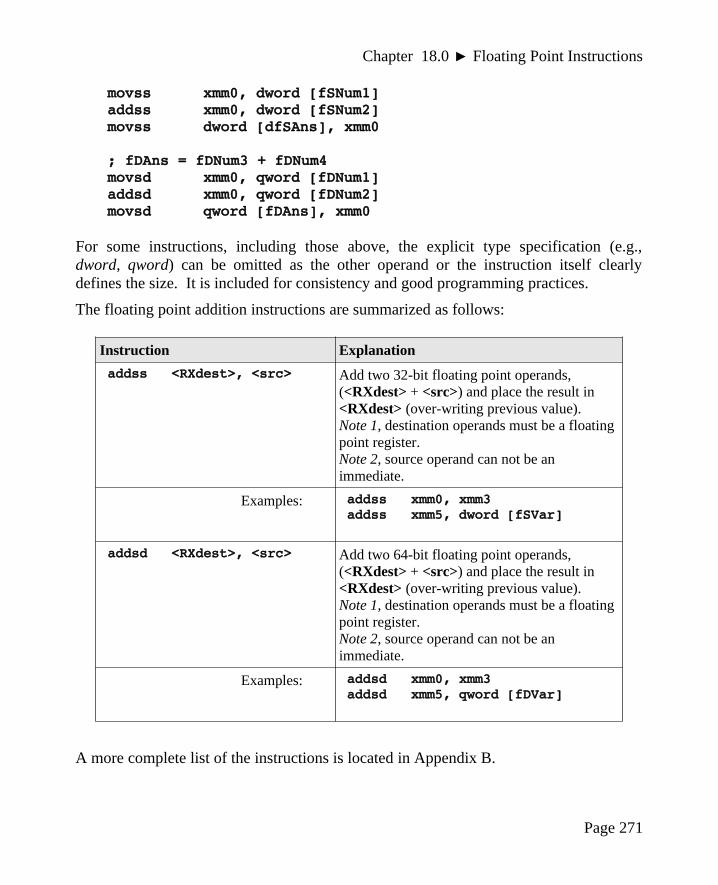
Chapter 18.0 ► Floating Point Instructions
movss xmm0, dword [fSNum1]addss xmm0, dword [fSNum2]movss dword [dfSAns], xmm0
; fDAns = fDNum3 + fDNum4movsd xmm0, qword [fDNum1]addsd xmm0, qword [fDNum2]movsd qword [fDAns], xmm0
For some instructions, including those above, the explicit type specification (e.g.,dword, qword) can be omitted as the other operand or the instruction itself clearlydefines the size. It is included for consistency and good programming practices.
The floating point addition instructions are summarized as follows:
Instruction Explanation
addss <RXdest>, <src> Add two 32-bit floating point operands, (<RXdest> + <src>) and place the result in <RXdest> (over-writing previous value).Note 1, destination operands must be a floating point register.Note 2, source operand can not be an immediate.
Examples: addss xmm0, xmm3 addss xmm5, dword [fSVar]
addsd <RXdest>, <src> Add two 64-bit floating point operands, (<RXdest> + <src>) and place the result in <RXdest> (over-writing previous value).Note 1, destination operands must be a floating point register.Note 2, source operand can not be an immediate.
Examples: addsd xmm0, xmm3 addsd xmm5, qword [fDVar]
A more complete list of the instructions is located in Appendix B.
Page 271
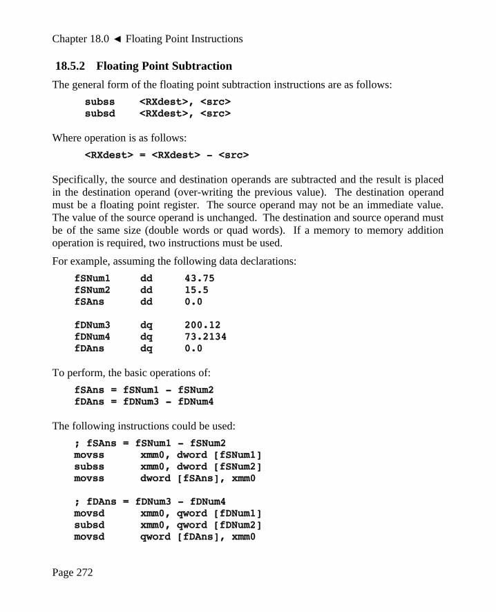
Chapter 18.0 ◄ Floating Point Instructions
18.5.2 Floating Point Subtraction
The general form of the floating point subtraction instructions are as follows:
subss <RXdest>, <src>subsd <RXdest>, <src>
Where operation is as follows:
<RXdest> = <RXdest> - <src>
Specifically, the source and destination operands are subtracted and the result is placedin the destination operand (over-writing the previous value). The destination operandmust be a floating point register. The source operand may not be an immediate value.The value of the source operand is unchanged. The destination and source operand mustbe of the same size (double words or quad words). If a memory to memory additionoperation is required, two instructions must be used.
For example, assuming the following data declarations:
fSNum1 dd 43.75fSNum2 dd 15.5fSAns dd 0.0
fDNum3 dq 200.12fDNum4 dq 73.2134fDAns dq 0.0
To perform, the basic operations of:
fSAns = fSNum1 - fSNum2fDAns = fDNum3 - fDNum4
The following instructions could be used:
; fSAns = fSNum1 - fSNum2movss xmm0, dword [fSNum1]subss xmm0, dword [fSNum2]movss dword [fSAns], xmm0
; fDAns = fDNum3 - fDNum4movsd xmm0, qword [fDNum1]subsd xmm0, qword [fDNum2]movsd qword [fDAns], xmm0
Page 272

Chapter 18.0 ► Floating Point Instructions
For some instructions, including those above, the explicit type specification (e.g.,dword, qword) can be omitted as the other operand or the instruction itself clearlydefines the size. It is included for consistency and good programming practices.
The floating point subtraction instructions are summarized as follows:
Instruction Explanation
subss <RXdest>, <src> Subtract two 32-bit floating point operands, (<RXdest> - <src>) and place the result in <RXdest> (over-writing previous value).Note 1, destination operands must be a floating point register.Note 2, source operand can not be an immediate.
Examples: subss xmm0, xmm3 subss xmm5, dword [fSVar]
subsd <RXdest>, <src> Subtract two 64-bit floating point operands, (<RXdest> - <src>) and place the result in <RXdest> (over-writing previous value).Note 1, destination operands must be a floating point register.Note 2, source operand can not be an immediate.
Examples: subsd xmm0, xmm3 subsd xmm5, qword [fDVar]
A more complete list of the instructions is located in Appendix B.
18.5.3 Floating Point Multiplication
The general form of the floating point multiplication instructions are as follows:
mulss <RXdest>, <src>mulsd <RXdest>, <src>
Where operation is as follows:
<RXdest> = <RXdest> * <src>
Page 273

Chapter 18.0 ◄ Floating Point Instructions
Specifically, the source and destination operands are multiplied and the result is placedin the destination operand (over-writing the previous value). The destination operandmust be a floating point register. The source operand may not be an immediate value.The value of the source operand is unchanged. The destination and source operand mustbe of the same size (double words or quad words). If a memory to memory additionoperation is required, two instructions must be used.
For example, assuming the following data declarations:
fSNum1 dd 43.75fSNum2 dd 15.5fSAns dd 0.0
fDNum3 dq 200.12fDNum4 dq 73.2134fDAns dq 0.0
To perform, the basic operations of:
fSAns = fSNum1 * fSNum2fDAns = fDNum3 * fDNum4
The following instructions could be used:
; fSAns = fSNum1 * fSNum2movss xmm0, dword [fSNum1]mulss xmm0, dword [fSNum2]movss dword [fSAns], xmm0
; fDAns = fDNum3 * fDNum4movsd xmm0, qword [fDNum1]mulsd xmm0, qword [fDNum2]movsd qword [fDAns], xmm0
For some instructions, including those above, the explicit type specification (e.g.,dword, qword) can be omitted as the other operand or the instruction itself clearlydefines the size. It is included for consistency and good programming practices.
Page 274

Chapter 18.0 ► Floating Point Instructions
The floating point multiplication instructions are summarized as follows:
Instruction Explanation
mulss <RXdest>, <src> Multiply two 32-bit floating point operands, (<RXdest> * <src>) and place the result in <RXdest> (over-writing previous value).Note 1, destination operands must be a floating point register.Note 2, source operand can not be an immediate.
Examples: mulss xmm0, xmm3 mulss xmm5, dword [fSVar]
mulsd <RXdest>, <src> Multiply two 64-bit floating point operands, (<RXdest> * <src>) and place the result in <RXdest> (over-writing previous value).Note 1, destination operands must be a floating point register.Note 2, source operand can not be an immediate.
Examples: mulsd xmm0, xmm3 mulsd xmm5, qword [fDVar]
A more complete list of the instructions is located in Appendix B.
18.5.4 Floating Point Division
The general form of the floating point division instructions are as follows:
divss <RXdest>, <src>divsd <RXdest>, <src>
Where operation is as follows:
<RXdest> = <RXdest> / <src>
Specifically, the source and destination operands are divided and the result is placed inthe destination operand (over-writing the previous value). The destination operand mustbe a floating point register. The source operand may not be an immediate value. Thevalue of the source operand is unchanged. The destination and source operand must be
Page 275

Chapter 18.0 ◄ Floating Point Instructions
of the same size (double words or quad words). If a memory to memory additionoperation is required, two instructions must be used.
For example, assuming the following data declarations:
fSNum1 dd 43.75fSNum2 dd 15.5fSAns dd 0.0
fDNum3 dq 200.12fDNum4 dq 73.2134fDAns dq 0.0
To perform, the basic operations of:
fSAns = fSNum1 / fSNum2fDAns = fDNum3 / fDNum4
The following instructions could be used:
; fSAns = fSNum1 / fSNum2movss xmm0, dword [fSNum1]divss xmm0, dword [fSNum2]movss dword [fSAns], xmm0
; fDAns = fDNum3 / fDNum4movsd xmm0, qword [fDNum1]divsd xmm0, qword [fDNum2]movsd qword [fDAns], xmm0
For some instructions, including those above, the explicit type specification (e.g.,dword, qword) can be omitted as the other operand or the instruction itself clearlydefines the size. It is included for consistency and good programming practices.
Page 276

Chapter 18.0 ► Floating Point Instructions
The floating point division instructions are summarized as follows:
Instruction Explanation
divss <RXdest>, <src> Divide two 32-bit floating point operands, (<RXdest> / <src>) and place the result in <RXdest> (over-writing previous value).Note 1, destination operands must be a floating point register.Note 2, source operand can not be an immediate.
Examples: divss xmm0, xmm3 divss xmm5, dword [fSVar]
divsd <RXdest>, <src> Divide two 64-bit floating point operands, (<RXdest> / <src>) and place the result in <RXdest> (over-writing previous value).Note 1, destination operands must be a floating point register.Note 2, source operand can not be an immediate.
Examples: divsd xmm0, xmm3 divsd xmm5, qword [fDVar]
A more complete list of the instructions is located in Appendix B.
18.5.5 Floating Point Square Root
The general form of the floating point square root instructions are as follows:
sqrtss <RXdest>, <src>sqrtsd <RXdest>, <src>
Where operation is as follows:
<dest> = √ <src>
Specifically, the square root of the source operand is placed in the destination operand(over-writing the previous value). The destination operand must be a floating pointregister. The source operand may not be an immediate value. The value of the sourceoperand is unchanged. The destination and source operand must be of the same size
Page 277

Chapter 18.0 ◄ Floating Point Instructions
(double words or quad words). If a memory to memory addition operation is required,two instructions must be used.
For example, assuming the following data declarations:
fSNum1 dd 1213.0fSAns dd 0.0
fDNum3 dq 172935.123fDAns dq 0.0
To perform, the basic operations of:
fSAns = √ fSNum1fDAns = √ fSNum3
The following instructions could be used:
; fSAns = sqrt (fSNum1)sqrtss xmm0, dword [fSNum1]movss dword [fSAns], xmm0
; fDAns = sqrt(fDNum3)sqrtsd xmm0, qword [fDNum3]movsd qword [fDAns], xmm0
For some instructions, including those above, the explicit type specification (e.g.,dword, qword) can be omitted as the other operand or the instruction itself clearlydefines the size. It is included for consistency and good programming practices.
The floating point addition instructions are summarized as follows:
Instruction Explanation
sqrtss <RXdest>, <src> Take the square root of the 32-bit floating pointsource operand and place the result in destination operand (over-writing previous value).Note 1, destination operands must be a floating point register.Note 2, source operand can not be an immediate.
Page 278

Chapter 18.0 ► Floating Point Instructions
Instruction Explanation
Examples: sqrtss xmm0, xmm3 sqrtss xmm7, dword [fSVar]
sqrtsd <RXdest>, <src> Take the square root of the 64-bit floating pointsource operand and place the result in destination operand (over-writing previous value).Note 1, destination operands must be a floating point register.Note 2, source operand can not be an immediate.
Examples: sqrtsd xmm0, xmm3 sqrtsd xmm7, qword [fDVar]
A more complete list of the instructions is located in Appendix B.
18.6 Floating Point Control Instructions
The control instructions refer to programming constructs such as IF statements andlooping. The integer comparison instruction, cmp, as described in Chapter 7 will notwork for floating point values.
The floating point comparison instructions compare two floating point values. Like theinteger comparisons, the result of the comparison is stored in the rFlag register andneither operand is changed. Immediately after the comparison, the rFlag register isaccessed to determine the results by using a conditional jump instruction. While allfloating point comparisons are signed, an unsigned conditional jump is used(ja/jae/jb/jbe). Program labels (i.e., a target of a conditional jump) are the same.
There are two forms of the floating point comparison, ordered and unordered. Theordered floating point comparisons can cause a number of exceptions. The unorderedfloating point comparisons can only cause an exception for a SNaN (signaling not anumber), more generically referred to as a NaN (not a number) as described in Chapter3, Data Representation.
The GNU C/C++ compiler favors the unordered floating point compare instruction.Since they are similar, this text will focus only on the unordered version.
Page 279

Chapter 18.0 ◄ Floating Point Instructions
18.6.1 Floating Point Comparison
The general form of the floating point comparison instructions are as follows:
ucomiss <RXsrc>, <src>ucomisd <RXsrc>, <src>
Where <RXsrc> and <src> are compared as floating point values and must be the samesize. The results of the comparison are placed in the rFlag register. Neither operand ischanged. The <RXsrc> operand must be one of the xmm registers. The <src> registercan be a xmm register or a memory location, but may not be an immediate value. Oneof the unsigned conditional jump instructions can be used to read the rFlag register.
The conditional control instructions include the jump equal (je) and jump not equal(jne). The unsigned conditional control instructions include the basic set of comparisonoperations; jump below than (jb), jump below or equal (jbe), jump above than (ja), andjump above or equal (jae).
The general form of the signed conditional instructions along with an explanatorycomment are as follows:
je <label> ; if <op1> == <op2>jne <label> ; if <op1> != <op2>
jb <label> ; unsigned, if <op1> < <op2>jbe <label> ; unsigned, if <op1> <= <op2>ja <label> ; unsigned, if <op1> > <op2>jae <label> ; unsigned, if <op1> >= <op2>
For example, given the following pseudo-code for floating point variables:
if (fltNum > fltMax)fltMax = fltNum;
And, assuming the following data declarations:
fltNum dq 7.5fltMax dq 5.25
Assuming that the values are updating appropriately within the program (not shown),the following instructions could be used:
movsd xmm1, qword [fltNum]ucomisd xmm1, qword [fltMax] ; if fltNum <= fltMax
Page 280

Chapter 18.0 ► Floating Point Instructions
jbe notNewFltMax ; skip set new maxmovsd qword [fltMax], xmm1
notNewFltMax:
As with integer comparisons, the floating point compare and conditional jump providefunctionality for jump or not jump. As such, if the condition from the original IFstatement is false, the code to update the fltMax should not be executed. Thus, whenfalse, in order to skip the execution, the conditional jump will jump to the target labelimmediately following the code to be skipped (not executed). While there is only oneline in this example, there can be many lines code.
A more complex example might be as follows:
if (x != 0.0) {ans = x / y;errFlg = FALSE;
} else {errFlg = TRUE;
}
This basic compare and conditional jump do not provide and IF-ELSE structure. It mustbe created. Assuming the x and y variables are signed double-words that will be setduring the program execution, and the following declarations:
TRUE equ 1FALSE equ 0fltZero dq 0.0x dq 10.1y dq 3.7ans dq 0.0errFlg db FALSE
The following code could be used to implement the above IF-ELSE statement.
movsd xmm1, qword [x]ucomisd xmm1, qword [fltZero] ; if statementje doElsedivsd xmm1, qword [y]movsd dword [ans], eaxmov byte [errFlg], FALSEjmp skpElse
Page 281

Chapter 18.0 ◄ Floating Point Instructions
doElse:mov byte [errFlg], TRUE
skpElse:
Floating point comparisons can be very tricky due to inexact nature of the floating pointrepresentations and rounding errors. For example, the value 0.1 added 10 times shouldbe 1.0. However, implementing a program to perform this summation and checking theresult, will show that;
∑i=1
10
0.1 ≠ 1.0
which can be very confusing for inexperienced programmers.
For more information regarding the details of floating point, refer to the popular articleWhat Every Computer Scientist Should Know about Floating Point Arithmetic46.
The floating point comparison instructions are summarized as follows:
Instruction Explanation
ucomiss <RXsrc>, <src> Compare two 32-bit floating point operands, (<RXsrct> + <src>). Results are placed in the rFlag register. Neither operand is changed.Note 1, <RXsrc> operands must be a floating point register.Note 2, source operand may be a floating point register or memory, but not be an immediate.
Examples: ucomiss xmm0, xmm3 ucomiss xmm5, dword [fSVar]
ucomisd <RXsrc>, <src> Compare two 64-bit floating point operands, (<RXsrct> + <src>). Results are placed in the rFlag register. Neither operand is changed.Note 1, <RXsrc> operands must be a floating point register.Note 2, source operand may be a floating point register or memory, but not be an immediate.
46 See: http://docs.oracle.com/cd/E19957-01/806-3568/ncg_goldberg.html
Page 282

Chapter 18.0 ► Floating Point Instructions
Instruction Explanation
Examples: ucomisd xmm0, xmm3 ucomisd xmm5, qword [fSVar]
A more complete list of the instructions is located in Appendix B.
18.7 Floating Point Calling Conventions
The standard calling conventions detailed in Chapter 12, Functions still fully apply.This section addresses the usage of the floating point registers when calling floatingpoint functions.
When using floating point registers, none of the registers are preserved across a floatingpoint function call.
The first eight (8) floating point arguments are passed in floating point registers xmm0 –xmm7. Any additional arguments are placed on the stack in backwards order in themanner described in Chapter 12, Functions. A value returning floating point functionwill return the result in xmm0.
Since none of the floating point registers are preserved, the code must be writtencarefully.
18.8 Example Program, Sum and Average
This example is a simple assembly language program to calculate the sum and averagefor a list of floating point values.
; Floating Point Example Program; ***********************************************************
section .data
; -----; Define constants.
NULL equ 0 ; end of stringTRUE equ 1FALSE equ 0
Page 283

Chapter 18.0 ◄ Floating Point Instructions
EXIT_SUCCESS equ 0 ; Successful operationSYS_exit equ 60 ; system call code for terminate
; -----
fltLst dq 21.34, 6.15, 9.12, 10.05, 7.75dq 1.44, 14.50, 3.32, 75.71, 11.87dq 17.23, 18.25, 13.65, 24.24, 8.88
length dd 15lstSum dq 0.0lstAve dq 0.0
; ***********************************************************section .textglobal _start_start:
; -----; Loop to find floating point sum.
mov ecx, [length]mov rbx, fltLstmov rsi, 0movsd xmm1, qword [lstSum]
sumLp:movsd xmm0, qword [rbx+rsi*8] ; get fltLst[i]addsd xmm1, xmm0 ; update suminc rsi ; i++loop sumLp
movsd qword [lstSum], xmm1 ; save sum
; -----; Compute average of entire list.
cvtsi2sd xmm0, dword [length]cvtsd2si dword [length], xmm0divsd xmm1, xmm0movsd qword [lstAve], xmm1
; -----
Page 284

Chapter 18.0 ► Floating Point Instructions
; Done, terminate program.
last:mov eax, SYS_exitmov ebx, EXIT_SUCCESS ; exit w/successsyscall
The debugger can be used to examine the results and verify correct execution of theprogram.
18.9 Example Program, Absolute Value
This example is a simple assembly language program to calculate the sum and averagefor a list of floating point values. Recall that if a value is negative, it must be madepositive and if the value is already positive, nothing should be done.
; Floating Point Absolute Value Example
section .data
; -----; Define constants.
TRUE equ 1FALSE equ 0
SUCCESS equ 0 ; successful operationSYS_exit equ 60 ; call code for terminate
; -----; Define some test variables.
dZero dq 0.0 dNegOne dq -1.0
fltVal dq -8.25
; *********************************************************section .textglobal _start_start:
Page 285

Chapter 18.0 ◄ Floating Point Instructions
; -----; Perform absolute value function on flt1
movsd xmm0, qword [fltVal]ucomisd xmm0, qword [dZero]jae isPosmulsd xmm0, qword [dNegOne]movsd qword [fltVal], xmm0
isPos:
; -----; Done, terminate program.
last:mov eax, SYS_exitmov ebx, EXIT_SUCCESS ; exit w/successsyscall
In this example, the final result for |fltVal| was saved to memory. Depending on the context, this may not be required.
18.10 Exercises
Below are some quiz questions and suggested projects based on this chapter.
18.10.1 Quiz Questions
Below are some quiz questions based on this chapter.
1) List the floating point registers.
2) How many bytes are used by single precision floating point values and howmany bytes are used for double precision floating point values?
3) Explain why 0.1 added 10 times does not equal 1.0.
4) Where is the result of a value returning floating point function such as sin(x)return the result?
5) For a value returning floating point function, which floating point registers mustbe preserved across the function call?
Page 286

Chapter 18.0 ► Floating Point Instructions
18.10.2 Suggested Projects
Below are some suggested projects based on this chapter.
1) Implement the example program to find the sum and average for a list of floatingpoint values. Use the debugger to execute the program and verify the finalresults.
2) Implement the floating point absolute value function as two macros, one fAbsffor 32-bit floating point values and fAbsd for 64-bit floating point values. Createa simple main program that uses each macro three times on various differentvalues. Use the debugger to execute the program and verify the results.
3) Implement a program to perform the summation;
∑i=1
10
0.1
Compare the results of the summation to the value 1.0 and display a message“Are Same” if the summation result equals 1.0 and the message “Are Not Same”if the result of the summation does not equal 1.0. Use the debugger as needed todebug the program. When working, execute the program without the debuggerand verify that the expected results are displayed to the console.
Page 287

Chapter 18.0 ◄ Floating Point Instructions
Page 288

19.0 Parallel ProcessingIn the context of computing, parallel processing47, or more generically concurrency48,refers to multiple processes appearing to execute simultaneously.
In broad terms, concurrency implies multiple different (not necessarily related)processes simultaneously making progress. This can be accomplished in multiple ways.For example, process A could be executing on core 0 while process B is simultaneouslyexecuting on core 1 thus executing in parallel. Another possibility is that the executionof process A and B could be interleaved on a single core where process A might executefor a period of time and then be paused while process B is then executed for a period oftime and then paused while process A is resumed. This continues until either or both arecompleted. If this interleaved execution is performed often and fast enough it willappear that each is executing simultaneously.
The term parallel processing implies that processes are executing simultaneously. Theseprocesses may be unrelated or working together as a coordinated unit to solve a singlecomplex problem.
This chapter provides an overview of some basic approaches to parallel processing asapplied to a single problem. Assume that a large problem can be divided into varioussub-problems and those sub-problems can be executed independently. The sub-solutions would be brought together to provide a final solution for the problem. If thesub-problems can be executed simultaneously, a final solution might be foundsignificantly faster than if the sub-problems are executed in series (one after another).The potential rewards for implementing concurrency are significant but so are thechallenges. Unfortunately, not all problems can be easily divided into such sub-problems.
47 For more information, refer to: http://en.wikipedia.org/wiki/Parallel_processing48 For more information, refer to: http://en.wikipedia.org/wiki/Concurrency_(computer_science)
Page 289
Chapter19
#define QUESTION ((bb) || !(bb))- Shakespeare

Chapter 19.0 ◄ Parallel Processing
The basic approaches to parallel processing are distributed computing49 andmultiprocessing50 (also referred to as threaded computations). Each approach isexplained with an emphasis on the technical issues associated with shared memorymultiprocessing. The larger topic of learning to create parallel algorithms is outside thescope of this text.
19.1 Distributed Computing
Distributed computing or distributed processing refers to the general idea of taking alarge problem, dividing it into multiple sub-problems, and executing the sub-problemson different computers connected through a network. Typically, a master or main servernode will distribute the sub-problems to various available computation nodes. Whencompleted, the computational nodes will send the intermediate results back to themaster. As needed, the master may send additional sub-problems to the computationalnodes. The master will also track and combine the intermediate results into a finalsolution. The details of how this is actually performed vary significantly and aredirectly related to the specifics of the problem.
There are many large scale examples of the distributed computing projects51. One suchproject is Folding@home52 which is a large distributed computing project for diseaseresearch that simulates protein folding, computational drug design, and other types ofmolecular dynamics. The project uses the idle processing resources of well over100,000 different personal computers owned by volunteers who have installed thesoftware on their systems.
This approach has the advantage of scaling to very large number of distributedcomputers. The disadvantages are associated with the communication limitationsassociated with the network.
19.2 Multiprocessing
As noted in Chapter 2, Architecture Overview, most current CPU chips include multiplecores. The CPU cores all have equal access to the main memory resource.Multiprocessing is a form of parallel processing that specifically refers to using multiplecores to perform simultaneous execution of multiple processes.
49 For more information, refer to: http://en.wikipedia.org/wiki/Distributed_computing50 For more information, refer to: http://en.wikipedia.org/wiki/Multiprocessing51 For more information, refer to: http://en.wikipedia.org/wiki/List_of_distributed_computing_projects52 For more information, refer to: http://en.wikipedia.org/wiki/Folding@home
Page 290

Chapter 19.0 ► Parallel Processing
Focusing on a single large project, a main or initial process might generate sub-process,referred to as threads53. When the initial process is started and placed in memory by thesystem loader54, the Operating System creates a new process including the requiredOperating System data structures, memory allocations, and page/swap file allotments. Athread is often referred to as a light-weight process since it will use the initial process’sallocations and address space thus making it quicker to create. It will also be quicker toterminate as the deallocations are not performed. Since the threads share memory withthe initial process and any other threads, this presents the potential for very fastcommunication between simultaneously executing threads. It also has the addedrequirement that the communications in the form of memory writes be carefullycoordinated to ensure results are not corrupted. Such a problem is referred to as a racecondition55. Race conditions are addressed in the following section.
The threaded approach will not scale to the extent of the distributed approach. CPUchips have limited number of cores which places an upper bound on the number ofsimultaneous computations that can occur. This limit does not apply to distributedcomputing. The limitations regarding network communication speeds do not apply tothreaded computations.
19.2.1 POSIX Threads
The POSIX Threads56, commonly called pThreads, is a widely available thread libraryon Ubuntu and many other operating systems. The example in this section will use thepThreads thread library Application Programmer Interface (API) for creating andjoining threads.
The initial or main process is created during the load process. The main process maycreate additional threads with the pthread_create() library function. While there isno specific limit to the number of threads that can be created, there is a limit to thenumber of cores available thus creating a practical limit for the number of threads.
The initial or main process can see if the thread has completed with thepthread_join() library function. If the thread has not completed, the join functionwill wait until it does. Ideally, in order to maximize the overall parallel operations, themain process would perform other computations while the thread or threads areexecuting and only check for thread completion when the other work has beencompleted.
53 For more information, refer to: http://en.wikipedia.org/wiki/Thread_(computing)54 For more information, refer to Chapter 5, Tool Chain55 For more information, refer to: http://en.wikipedia.org/wiki/Race_condition56 For more information, refer to: http://en.wikipedia.org/wiki/POSIX_Threads
Page 291

Chapter 19.0 ◄ Parallel Processing
There are other pThread functions to address mutexes57, condition variables, andsynchronization58 between threads which are not addressed in this very brief overview.
It should be noted that there are other approaches to threading not addressed here.
19.2.2 Race Conditions
A race condition is a generic term referring to when multiple threads simultaneouslywrite to the same location at the same time. Threaded programming is typically done ina high level language. However, fully understanding the specific cause of a racecondition is best done at the assembly language level.
A simple example is provided to purposely create a race condition and examine theproblem in detail. This example is not computationally useful.
Assuming we wish to compute the following formula MAX times, where MAX is adefined constant. For example;
myValue = (myValue
X ) + Y
We could write a high level language program something along the lines of:
for (int i=0; i < MAX; i++)myValue = (myValue / X) + Y;
If we wish to speed-up this computation, perhaps because MAX is extremely large, wemight create two thread functions, each to perform MAX/2 computations. Each of thethread functions would have shared access to the variables myValue, X, and Y. Thus,the code might be;
for (int i=0; i < MAX/2; i++)myValue = (myValue / X) + Y;
This code would be repeated in each of the thread functions. It may not be obvious, butassuming both threads are simultaneously executing, this will cause a race condition onthe myValue variable. Specifically, each of the two threads are attempting to update thevariable simultaneously and some of the updates to the variable may be lost.
To further simplify this example, we will assume that X and Y are both set to 1. Assuch, the result of each calculation would be to increment myValue by 1. If myValue is
57 For more information, refer to: http://en.wikipedia.org/wiki/Mutual_exclusion58 For more information, refer to: http://en.wikipedia.org/wiki/Synchronization_(computer_science)
Page 292

Chapter 19.0 ► Parallel Processing
initialized to 0, repeating the calculation MAX times, should result in myValue being setto MAX. This simplification will allow easy verification of the results. It is notcomputationally useful in any meaningful way.
Implementing this in assembly would first require a main program that creates each ofthe two threads. Then, each of the thread functions would need to be created. In thisvery simple example, each thread function would be the same (performing MAX/2iterations and that MAX is an even number).
Assuming one of the thread functions is named threadFunction0() and given the belowpThread thread data structure;
pthreadID0 dd 0, 0, 0, 0, 0
The following code fragment would create and start threadFunction0() executing.
; pthread_create(&pthreadID0, NULL,; &threadFunction0, NULL);
mov rdi, pthreadID0 mov rsi, NULL mov rdx, threadFunction0 mov rcx, NULL call pthread_create
This would need to be performed for each thread function.
The following code fragment will check if a thread function is completed;
; pthread_join (pthreadID0, NULL); mov rdi, qword [pthreadID0] mov rsi, NULL call pthread_join
If the thread function is not done, the join call will wait until it is completed.
The thread function, threadFunction0(), itself might contain the following code;
; ----- global threadFunction0 threadFunction0:
; Perform MAX / 2 iterations to update myValue.
mov rcx, MAX
Page 293

Chapter 19.0 ◄ Parallel Processing
shr rcx, 1 ; divide by 2mov r10, qword [x]mov r11, qword [y]
incLoop0: ; myValue = (myValue / x) + y
mov rax, qword [myValue] cqodiv r10add rax, r11mov qword [myValue], raxloop incLoop0
ret
The code for the second thread function would be similar.
If both threads are simultaneously executing, they are both trying to update the myValuevariable. For example, assuming that thread function 0 is executing on core 0 andthread function 1 is executing on core 1 (arbitrarily chosen), the following executiontrace is possible;
Step Code: Core 0, Thread 0 Code: Core 1, Thread 1
1 mov rax, qword [myValue]
2 cqo mov rax, qword [myValue]
3 div qword [x] cqo
4 add rax, qword [y] div qword [x]
5 mov qword [myValue], rax add rax, qword [y]
6 mov qword [myValue], rax
As a reminder, each core has its own set of registers. Thus, the core 0 rax register isdifferent than the core 1 rax register.
If the variable myValue is currently at 730, two thread executions should increase it to732. On core 0 code, at step 1 the 730 is copied into core 0, rax. On core 2, at step 2,the 730 is copied into core 1, rax. As execution progresses, steps 2-4 are performed andcore 0 rax is incremented from 730 to 731. During this time, on core 1, steps 1-3 are
Page 294

Chapter 19.0 ► Parallel Processing
completed and the 730 is also incremented to 731. As the next step, step5, is executedon core 0, the 731 is written to myValue variable. As the next step, step 6 is executedon core 1, the value 731 is again written to the myValue variable. Two executionstraces should have incremented the variable twice. However, since the value wasobtained in core 1 before core 0 was able to write the final value, one of the incrementswas lost or duplicated. The end result of this overlap is that the final value of myValuewill not be correct. And, since the amount of overlapping execution is not predictable,the degree of incorrectness is not easily predicted and may vary between differentexecutions.
For example, if the value of MAX is fairly small, such as 10,000, there would not likelybe any overlap. Each thread would start and complete so quickly, that the chances ofoverlapping execution would be very small. The problem still exists but would likelyappear correct on most executions, making it easy to ignore occasional anomalousoutput. As MAX is increased, the odds of overlapping execution increase.
Such problems can be very challenging to debug and require an understanding of thelow-level operations and the technical architecture.
19.3 Exercises
Below are some quiz questions and suggested projects based on this chapter.
19.3.1 Quiz Questions
Below are some quiz questions based on this chapter.
1) Explain the difference between concurrency and parallel processing.
2) Name the two common approaches to parallel computations.
3) In distributed processing, where might the parallel computations take place?
4) Provide the names of two examples of large distributed computing projects.Include a one-sentence description of each.
5) In multiprocessing, where might the parallel computations take place?
6) Provide one advantage and one disadvantage of the distributed computingapproach to parallel processing.
7) Provide one advantage and one disadvantage of the multiprocessing approach toparallel processing.
8) Explain what a race condition is?
Page 295

Chapter 19.0 ◄ Parallel Processing
9) Will a race condition occur when a shared variable is read by multiplesimultaneously executing threads? Explain why or why not.
10) Will a race condition occur when a shared variable is written by multiplesimultaneously executing threads (without any coordination)? Explain why orwhy not.
19.3.2 Suggested Projects
Below are some suggested projects based on this chapter.
1) Implement the outlined example program create two thread functions where eachthread function computes the formula MAX/2 times. Set MAX to 1,000,000,000(one billion).
1. Initially, structure the main function to call the first thread function and waituntil it completes until creating the second thread function and waiting untilit completes. This will force the threads to execute sequentially (not inparallel). Include a function to convert the integer into a string and displaythe result to the console. Use the debugger as necessary to debug theprogram. When working, execute the program without the debugger andverify that the displayed results for results is the same as MAX.
2. Use the Unix time59 command to establish a base execute time. Use the totalelapsed time.
3. Restructure the program so that both threads are the created thus allowing theexecution of the threads to occur in parallel. Use the debugger as necessaryto debug the program. When working, execute the program without thedebugger and note the final value of MAX. Ensure a fully understanding ofwhy displayed value for MAX is incorrect. Additionally, use the Unix timecommand on the modified program verify that it uses less elapsed time.
2) Update the program from the previous question to resolve the race condition.Use the debugger as necessary to debug the program. One very simple way toaccomplish this is to use temporary variables for each thread and combine themafter both thread functions have completed and display the final combined result.When working, execute the program without the debugger and verify that thedisplayed results for results is the same as MAX.
59 For more information, refer to: http://en.wikipedia.org/wiki/Time_(Unix)
Page 296

20.0 InterruptsIn a general sense, an interrupt60 is a pause or hold in the current flow. For example, ifyou are talking on the phone and the door bell rings, the phone conversation is placed onhold, and the door answered. After the salesperson is sent away, the phone conversationis resumed (where the conversation left off).
In computer programming an interrupt is also a pause, or hold, of the currentlyexecuting process. Typically, the current process is interrupted so that some other workcan be performed. An interrupt is usually defined as an event that alters the sequence ofinstructions executed by a processor. Such events correspond to signals generated bysoftware and/or hardware. For example, most Input/Output (I/O) devices generate aninterrupt in order to transmit or receive data. Software programs can also generateinterrupts to initiate I/O as needed, request OS services, or handle unexpectedconditions.
Handling interrupts is a sensitive task. Interrupts can occur at any time, the kernel triesto get the interrupt addressed as soon as possible. Additionally, an interrupt can beinterrupted by another interrupt.
20.1 Multi-user Operating System
A modern multi-user Operating System (OS) supports multiple programs executing, orappearing to be executing, simultaneously by sharing resources as necessary. The OS isresponsible for managing and sharing the resources. These resources include the CPUcores, primary memory (i.e., RAM), secondary storage (i.e., disk or SSD), displayscreen, keyboard, and mouse. For example, multiple programs must share the availableCPU resources (core or cores as applicable).
The interrupt mechanism is the primary means that the OS uses in order to provide theresource sharing. Consequently, understanding how interrupts are processed by the
60 For more information, refer to: http://en.wikipedia.org/wiki/Interrupt
Page 297
Chapter20
If a program is useful, it must be changed.If a program is useless, it must be documented.

Chapter 20.0 ◄ Interrupts
computer provides insight into how the operating system is able to provide multi-processing functions. When an interrupt occurs, the current process is interrupted (i.e.,placed on hold), the interrupt is handled (which depends on the specific reason for theinterrupt), and then eventually the process is resumed. The OS may choose to performother tasks or processes before the original process is resumed. The interrupt is handledby a special software routine called an Interrupt Service Routine (also called InterruptHandler, Device Driver, etc.). By using interrupts and quickly switching betweenvarious processes, the OS is able to provide the illusion that all processes are executingsimultaneously.
Not all code can be interrupted. For example, due to the nature of some operatingsystem kernel functions, there are regions in the kernel which must not be interrupted atall. This includes updating some sensitive operating system data structures.
20.1.1 Interrupt Classification
To better understand interrupts and interrupt processing, some background on the timingand categories of interrupts is useful.
20.1.2 Interrupt Timing
The timing of interrupts may occur synchronously or asynchronously. These terms arefairly common terms in computer processing and are explained in the followingsections.
20.1.2.1 Asynchronous Interrupts
In the context of computer interrupts, an asynchronously occurring interrupt means thatthe interrupt may occur at an arbitrary time with respect to program execution.Asynchronous interrupts are unpredictable relative to any specific location within theexecuting process. For example, an external hardware device might interrupt thecurrently executing process at an unpredictable location.
20.1.2.2 Synchronous Interrupts
Synchronously occurring interrupts typically occur while under CPU control and arecaused by or on behalf of the currently executing process. The synchronous nature isrelated to where the interrupt occurs and not a specific clock time or CPU cycle time.Synchronous interrupts typically reoccur at the same location (assuming nothing haschanged to resolve the original cause).
Page 298

Chapter 20.0 ► Interrupts
20.1.3 Interrupt Categories
Interrupts are typically categorized as hardware or software.
20.1.3.1 Hardware Interrupt
Hardware interrupts are typically generated by hardware. Hardware interrupts can beissued by
• I/O devices (keyboard, network adapter, etc.)
• Interval timers
• Other CPUs (on multiprocessor systems)
Hardware interrupts are asynchronously occurring. An example of a hardware interruptis when a key is typed on the keyboard. The OS can not know ahead of time when, oreven if, the key will be pressed. To handle this situation, the keyboard support hardwarewill generate an interrupt. If the OS is executing an unrelated program, that program istemporarily interrupted while the key is processed. In this example, that specificprocessing consists of storing the key in a buffer and returning to the interruptedprocess. Ideally, this brief interruption will have little impact in the interrupted process.
20.1.3.1.1 Exceptions
An exception is a term for an interrupt that is caused by the current process and needsattention of the kernel. Exceptions are synchronously occurring. In this context,synchronous implies that the exception will occur in a predictable or repeatable manner.
Exceptions are typically divided into categories as follows:
• Faults
• Traps
• Abort
An example of a fault is a page fault which is a request for loading part of the programfrom disk storage into memory. The interrupted process restarts with no loss ofcontinuity.
A trap is typically used for debugging. The process re-starts with no loss of continuity.
An abort is typically an indication that a serious error condition occurred and must behandled. This includes division by zero, attempt to access an invalid memory address,or attempt to execute an invalid/illegal instruction. An illegal instruction might be aninstruction that is only allowed to be executed by privileged/authorized processes. An
Page 299

Chapter 20.0 ◄ Interrupts
invalid instruction might be caused by attempting to execute a data item (which will notmake sense). Based on the severity of the error condition, the process is oftenterminated. If the process is not terminated, another routine may be executed to attemptto resolve the problem and re-execute the original routine (but not necessarily from theinterrupted location). The C/C++/Java try/catch block is an example of this.
It must be noted that there is not an absolute agreed upon definition for these terms.Some texts use slightly different terminology.
20.1.3.2 Software Interrupts
A software interrupt is produced by the CPU while processing instructions. This istypically a programmed exception explicitly requested by the programmer. Suchinterrupts are typically synchronously occurring and often used to request systemservices from the OS. For example, requesting system services such as I/O.
20.2 Interrupt Types and Levels
Interrupts have various types and privileges associated with them. The followingsections provide an explanation of the types and privileges. Interrupted processes mayexecute at a lower privilege than the interrupt processing code. In order for interrupts tobe effective, the OS must securely handle this privilege escalation and deescalationsecurely and quickly.
20.2.1 Interrupt Types
The two different types or kinds of interrupts are:
• Maskable interrupts
• Non-maskable interrupts
Maskable interrupts are typically issued by I/O devices. As the name 'maskable'implies, maskable interrupts can be ignored, or masked, for a short time period. Thisallows the associated interrupt processing to be delayed.
Non-maskable interrupts (NMI's) must be handled immediately. This includes some OSfunctions and critical malfunctions such as hardware failures. Non-maskable interruptsare always processed by the CPU.
20.2.2 Privilege Levels
Privilege Levels refer to the privilege level at which the interrupt code executes. Thismay be a higher privilege level than the interrupted code is executing. The processor
Page 300

Chapter 20.0 ► Interrupts
executes code in one of four privilege levels as follows:
Level Description
Level 0 Full access to all hardware resources (no restrictions). Used by only the lowest level OS functions.
Level 1 Somewhat restricted access to hardware resources. Used by library routines and software that interacts with hardware.
Level 2 More restricted access to hardware resources. Used by library routines and software that has limited access to some hardware.
Level 3 No direct access to hardware resources. Application programs run at this level.
Should an application program executing at level 3 be interrupted by a hardwareinterrupt for the keyboard, the keyboard interrupt handler must execute at level 0.
The following diagram shows the relationship of the levels.
The operating system interrupt processing mechanism will handle this privilege
Page 301
Illustration 28: Privilege Levels
Level 0
Level 1
Level 2
Level 3

Chapter 20.0 ◄ Interrupts
elevation and restoration in a secure manner. That requires that the interrupt source andprivileges be verified as part of the interrupt handling mechanism.
20.3 Interrupt Processing
When an interrupt occurs, it must be handled or processed securely, quickly, andcorrectly. The general idea is that when the currently executing process is interrupted itmust be placed on hold, and the appropriate interrupt handing code found and executed.The specific interrupt processing required depends on the cause or purpose of theinterrupt. Once the interrupt is serviced, the original process execution will eventuallybe resumed.
20.3.1 Interrupt Service Routine (ISR)
The code that is executed in response to an interrupt is typically called an InterruptService Routine or ISR. The code is sometimes referred to as interrupt handler, handler,service routine, or TSR code. For consistency, this document will use the term ISR.
ISR code is challenging to develop due to the issues related to the concurrency and raceconditions. Additionally, it is difficult to isolate problems and debug ISR code.
20.3.2 Processing Steps
The general steps involved in processing an interrupt are outlined in the followingsections.
20.3.2.1 Suspension
The execution of current program is suspended. As a minimum, this requires saving therip and rFlags registers to system stack. The remaining registers are likely to bepreserved (as a further step), depending on the specific interrupt. The rFlags flagregister must be preserved immediately since the interrupt may have been generatedasynchronously and those registers will change as successive instructions are executed.This multi-stage process ensures that the program context can be fully restored.
20.3.2.2 Obtaining ISR Address
The ISR addresses are stored in a table referred to as an Interrupt Descriptor Table61
(IDT). For each ISR, the IDT contains the ISR address and some additional informationincluding task gate (priority and privilege information) for the ISR. Each entry in theIDT is a total of 8 bytes each for a total of 16 bytes per IST entry. There are a maximum
61 Note, for Windows this data structure is referred to as the Interrupt Vector Table (IVT).
Page 302

Chapter 20.0 ► Interrupts
of 256 (0-255) possible entries in the IDT.
To obtain the starting address of an ISR, the interrupt number is multiplied by 16 (sinceeach entry is 16 bytes) which is used as offset into the IDT where the ISR address isobtained (for that interrupt).
The start of the IDT is pointed to by a dedicated register, IDTR, which is only accessibleby the OS and requires level 0 privilege to access.
The addresses of the ISR routines are specific to the OS version and the specifichardware complement of the system. The IDT is created when the system initially bootsand reflects the specific system configuration. This is critical in order for the OS towork correctly and consistently on different system hardware configurations.
20.3.2.3 Jump to ISR
Once the ISR address is obtained from the IDT some validation is performed. Thisincludes ensuring the interrupt is from a legal/valid source and if a privilege levelchange is required and allowed. Once the verifications have been completedsuccessfully, the address of the ISR from the IDT is placed in the rip register, thuseffecting a jump to the ISR routine.
20.3.2.4 Suspension Execute ISR
At this point, depending on the specific ISR, a complete process context switch may beperformed. A process context switch involves saving the entire set of CPU registers forthe interrupted process.
In Linux-based OS's, ISR are typically divided into two parts, referred to as the top-halfand bottom-half. Other OS's refer to these as the First-Level Interrupt Handler (FLIH)and the Second-Level Interrupt Handlers (SLIH).
The top-half or FLIH is executed immediately and is where any critical activities areperformed. The activities are specific to the ISR, but might include acknowledging theinterrupt, resetting hardware (if necessary), and recording any information onlyavailable at the time of interrupt. The top-half may perform some blocking of otherinterrupts (which needs to be minimized).
The bottom-half is where any processing activities (if any) are performed. This helpsensure that the top-half is completed quickly and that any non-critical processing isdeferred to a more convenient time. If a bottom-half exists, the top-half will create andschedule the execution of the bottom-half.
Once the top-half completes, the OS scheduler will select a new process.
Page 303

Chapter 20.0 ◄ Interrupts
20.3.2.5 Resumption
When the OS is ready to resume the interrupted process, the program context is restoredand an iret instruction is executed (to pop rFlags and rip registers, thus completingthe restoration).
20.4 Suspension Interrupt Processing Summary
The following diagram presents an overview of the general flow used for processinginterrupts by the system.
Page 304
Illustration 29: Interrupt Processing Overview
IDT
ExecutingProcess
OperatingSystem
ISR
Main Memory
23
1
5
4

Chapter 20.0 ► Interrupts
The steps are details as follows:
1. Execution of current program is suspended
- save rip and rFlags registers to stack
2. Obtain starting address of Interrupt Service Routine (ISR)
- interrupt number multiplied by 16
- used as offset into Interrupt Descriptor Table (IDT)
- obtains ISR address (for that interrupt) from IDT
3. Jump to Interrupt Service Routine
- set rip to address from IDT
4. Interrupt Service Routine Executes
- save context (i.e., any additional registers altered)
- process interrupt (specific to interrupt generated)
- schedule any later data processing activities
5. Interrupted Process Resumption
- resume scheduling based on OS scheduler
- restore context
- perform iret (to pop rFlags and rip registers)
This interrupt processing mechanism allows a dynamic, run-time lookup for the ISRaddress.
20.5 Exercises
Below are some quiz questions and suggested projects based on this chapter.
20.5.1 Quiz Questions
Below are some quiz questions based on this chapter.
1) What is the operating system responsible for? Name some of the resources.
2) What is an interrupt?
3) What is an exception?
Page 305

Chapter 20.0 ◄ Interrupts
4) What is an ISR and what is it for?
5) Where (name of the data structure) does the operating system obtain the addresswhen an interrupt occurs and what is contained in it?
6) When an interrupt occurs, how the appropriate offset into the IDT calculated?
7) What is the difference between the iret and ret instructions?
8) Why does the OS use the interrupt mechanism instead of just performing astandard call.
9) What is meant by asynchronously occurring interrupts?
10) What is meant by synchronously occurring interrupts?
11) When an interrupt occurs, the rip and rFlags registers are pushed on the stack.Much like the call statement, the rip register is pushed to save the return address.Explain why is the rFlag register pushed on the stack.
12) Name two hardware interrupts.
13) List one way for a program to generate an exception.
14) What is the difference between a maskable and non-maskable interrupt?
20.5.2 Suggested Projects
Below are some suggested projects based on this chapter.
1) Write a program to obtain and list the contents of the IDT. This will require aninteger to ASCII/Hex program in order to display the applicable addresses inhex. Use the debugger as necessary to debug the program. When working,execute the program without the debugger to displayed results.
Page 306

21.0 Appendix A – ASCII TableThis appendix provides a copy of the ASCII Table for reference.
Char Dec Hex Char Dec Hex Char Dec Hex Char Dec Hex
NUL 0 0x00 spc 32 0x20 @ 64 0x40 ` 96 0x60
SOH 1 0x01 ! 33 0x21 A 65 0x41 a 97 0x61
STX 2 0x02 " 34 0x22 B 66 0x42 b 98 0x62
ETX 3 0x03 # 35 0x23 C 67 0x43 c 99 0x63
EOT 4 0x04 $ 36 0x24 D 68 0x44 d 100 0x64
ENQ 5 0x05 % 37 0x25 E 69 0x45 e 101 0x65
ACK 6 0x06 & 38 0x26 F 70 0x46 f 102 0x66
BEL 7 0x07 ' 39 0x27 G 71 0x47 g 103 0x67
BS 8 0x08 ( 40 0x28 H 72 0x48 h 104 0x68
TAB 9 0x09 ) 41 0x29 I 73 0x49 i 105 0x69
LF 10 0x0A * 42 0x2A J 74 0x4A j 106 0x6A
VT 11 0x0B + 43 0x2B K 75 0x4B k 107 0x6B
FF 12 0x0C , 44 0x2C L 76 0x4C l 108 0x6C
CR 13 0x0D - 45 0x2D M 77 0x4D m 109 0x6D
SO 14 0x0E . 46 0x2E N 78 0x4E n 110 0x6E
SI 15 0x0F / 47 0x2F O 79 0x4F o 111 0x6F
DLE 16 0x10 0 48 0x30 P 80 0x50 p 112 0x70
DC1 17 0x11 1 49 0x31 Q 81 0x51 q 113 0x71
DC2 18 0x12 2 50 0x32 R 82 0x52 r 114 0x72
DC3 19 0x13 3 51 0x33 S 83 0x53 s 115 0x73
Page 307
AppendixA

Appendix A – ASCII Table
DC4 20 0x14 4 52 0x34 T 84 0x54 t 116 0x74
NAK 21 0x15 5 53 0x35 U 85 0x55 u 117 0x75
SYN 22 0x16 6 54 0x36 V 86 0x56 v 118 0x76
ETB 23 0x17 7 55 0x37 W 87 0x57 w 119 0x77
CAN 24 0x18 8 56 0x38 X 88 0x58 x 120 0x78
EM 25 0x19 9 57 0x39 Y 89 0x59 y 121 0x79
SUB 26 0x1A : 58 0x3A Z 90 0x5A z 122 0x7A
ESC 27 0x1B ; 59 0x3B [ 91 0x5B { 123 0x7B
FS 28 0x1C < 60 0x3C \ 92 0x5C | 124 0x7C
GS 29 0x1D = 61 0x3D ] 93 0x5D } 125 0x7D
RS 30 0x1E > 62 0x3E ^ 94 0x5E ~ 126 0x7E
US 31 0x1F ? 63 0x3F _ 95 0x5F DEL 127 0x7F
For additional information and a more complete listing of the ASCII codes (including the extended ASCII characters), refer to http://www.asciitable.com/
Page 308

22.0 Appendix B – Instruction Set SummaryThis appendix provides a listing and brief description of the instructions covered in thistext. This set of instructions is a subset of the complete instruction set. For a completelisting of the instructions, refer to the references noted in chapter 1.
22.1 Notation
The following table summarizes the notational conventions used.
Operand Notation Description
<reg> Register operand. The operand must be a register.
<reg8>, <reg16>,<reg32>, <reg64>
Register operand with specific size requirement. For example, reg8 means a byte sized register (e.g., al, bl, etc.) only and reg32 means a double-word sized register (e.g., eax, ebx, etc.) only.
<dest> Destination operand. The operand may be a register or memory. Since it is a destination operand, the contents will be over written with the new result (based on the specific instruction).
<RXdest> Floating point destination register operand. The operand must be a floating point register. Since it is a destination operand, the contents will be over written with the new result (based on the specific instruction).
<src> Source operand. Operand value is unchanged after the instruction.
<imm> Immediate value. May be specified in decimal, hex, octal,or binary.
Page 309
AppendixB

Appendix B – Instruction Set Summary
Operand Notation Description
<mem> Memory location. May be a variable name or an indirect reference (i.e., a memory address).
<op> or <operand> Operand, register or memory.
<op8>, <op16>,<op32>, <op64>
Operand, register or memory, with specific size requirement. For example, op8 means a byte sized operand only and reg32 means a double-word sized operand only.
<label> Program label.
22.2 Data Movement Instructions
Below is a summary of the basic data movement and addressing instructions.
Instruction Explanation
mov <dest>, <src> Copy source operand to the destination operand.Note 1, both operands can not be memory.Note 2, destination operands can not be an immediate.
lea <reg64>, <mem> Place address of <mem> into reg64.
22.3 Data Conversion instructions
Below is a summary of the basic data conversion instructions.
Instruction Explanation
movzx <dest>, <src> movzx <reg16>, <op8> movzx <reg32>, <op8> movzx <reg32>, <op16> movzx <reg64>, <op8> movzx <reg64>, <op16>
Unsigned widening conversion.Note 1, both operands can not be memory.Note 2, destination operands can not be an immediate.Note 3, immediate values not allowed.
cbw Convert byte in al into word in ax.Note, only works for al to ax register.
Page 310

Appendix B – Instruction Set Summary
Instruction Explanation
cwd Convert word in ax into double-word in dx:ax.Note, only works for ax to dx:ax registers.
cwde Convert word in ax into word into double-wordin eax.Note, only works for ax to eax register.
cdq Convert double-word in eax into quadword in edx:eax.Note, only works for eax to edx:eax registers.
cdqe Convert double-word in eax into quadword in rax.Note, only works for rax register.
cqo Convert quadword in rax into word in double-quadword in rdx:rax.Note, only works for rax to rdx:rax registers.
movsx <dest>, <src> movsx <reg16>, <op8> movsx <reg32>, <op8> movsx <reg32>, <op16> movsx <reg64>, <op8> movsx <reg64>, <op16> movsxd <reg64>, <op32>
Signed widening conversion (via sign extension).Note 1, both operands can not be memory.Note 2, destination operands can not be an immediate.Note 3, immediate values not allowed.
22.4 Integer Arithmetic Instructions
Below is a summary of the basic integer arithmetic instructions.
Instruction Explanation
add <dest>, <src> Add two operands, (<dest> + <src>) and placethe result in <dest> (over-writing previous value).Note 1, both operands can not be memory.Note 2, destination operand can not be an immediate.
inc <operand> Increment <operand> by 1.Note, <operand> can not be an immediate.
Page 311

Appendix B – Instruction Set Summary
Instruction Explanation
adc <dest>, <src> Add two operands, (<dest> + <src>) and any previous carry (stored in the carry bit in the rFlag register) and place the result in <dest> (over-writing previous value).Note 1, both operands can not be memory.Note 2, destination operand can not be an immediate.
Examples: adc rcx, qword [dVvar1] adc rax, 42
sub <dest>, <src> Add two operands, (<dest> - <src>) and place the result in <dest> (over-writing previous value).Note 1, both operands can not be memory.Note 2, destination operand can not be an immediate.
dec <operand> Decrement <operand> by 1.Note, <operand> can not be an immediate.
mul <src>
mul <op8> mul <op16> mul <op32> mul <op64>
Multiply A register (al, ax, eax, or rax) times the <src> operand.
Byte: ax = al * <src>Word: dx:ax = ax * <src>Double: edx:eax = eax * <src>Quad: rdx:rax = rax * <src>
Note, <src> operand can not be an immediate.
imul <src> imul <dest>, <src/imm32> imul <dest>, <src>, <imm32>
imul <op8> imul <op16> imul <op32> imul <op64> imul <reg16>, <op16/imm> imul <reg32>, <op32/imm> imul <reg64>, <op64/imm> imul <reg16>, <op16>, <imm> imul <reg32>, <op32>, <imm> imul <reg64>, <op64>, <imm>
Signed multiply instruction.
For single operand:Byte: ax = al * <src>Word: dx:ax = ax * <src>Double: edx:eax = eax * <src>Quad: rdx:rax = rax * <src>
Note, <src> operand can not be an immediate.For two operands:
<reg16> = <reg16> * <op16/imm><reg32> = <reg32> * <op32/imm><reg64> = <reg64> * <op64/imm>
Page 312

Appendix B – Instruction Set Summary
Instruction Explanation
For three operands:<reg16> = <op16> * <imm><reg32> = <op32> * <imm><reg64> = <op64> * <imm>
div <src>
div <op8> div <op16> div <op32> div <op64>
Unsigned divide A/D register (ax, dx:ax, edx:eax, or rdx:rax) by the <src> operand.
Byte: al = ax / <src>, rem in ahWord: ax = dx:ax / <src>, rem in dxDouble: eax = eax / <src>, rem in edxQuad: rax = rax / <src>, rem in rdx
Note, <src> operand can not be an immediate.
idiv <src>
idiv <op8> idiv <op16> idiv <op32> idiv <op64>
Signed divide A/D register (ax, dx:ax, edx:eax, or rdx:rax) by the <src> operand.
Byte: al = ax / <src>, rem in ahWord: ax = dx:ax / <src>, rem in dxDouble: eax = eax / <src>, rem in edxQuad: rax = rax / <src>, rem in rdx
Note, <src> operand can not be an immediate.
22.5 Logical, Shift, and Rotate Instructions
Below is a summary of the basic logical, shift, arithmetic shift, and rotate instructions.
Instruction Explanation
and <dest>, <src> Perform logical AND operation on two operands, (<dest> and <src>) and place the result in <dest> (over-writing previous value).Note 1, both operands can not be memory.Note 2, destination operand can not be an immediate.
or <dest>, <src> Perform logical OR operation on two operands,(<dest> || <src>) and place the result in <dest>(over-writing previous value).Note 1, both operands can not be memory.Note 2, destination operand can not be an immediate.
Page 313

Appendix B – Instruction Set Summary
Instruction Explanation
xor <dest>, <src> Perform logical XOR operation on two operands, (<dest> ^ <src>) and place the result in <dest> (over-writing previous value).Note 1, both operands can not be memory.Note 2, destination operand can not be an immediate.
not <op> Perform a logical not operation (one's complement on the operand 1's→0's and 0's→1's).Note, operand can not be an immediate.
shl <dest>, <imm> shl <dest>, cl
Perform logical shift left operation on destination operand. Zero fills from left (as needed).The <imm> or the value in cl register must be between 1 and 64.Note, destination operand can not be an immediate.
shr <dest>, <imm> shr <dest>, cl
Perform logical shift right operation on destination operand. Zero fills from right (as needed).The <imm> or the value in cl register must be between 1 and 64.Note, destination operand can not be an immediate.
sal <dest>, <imm> sal <dest>, cl
Perform arithmetic shift left operation on destination operand. Zero fills from left (as needed).The <imm> or the value in cl register must be between 1 and 64.Note, destination operand can not be an immediate.
sar <dest>, <imm> sar <dest>, cl
Perform arithmetic shift right operation on destination operand. Zero fills from right (as needed).The <imm> or the value in cl register must be between 1 and 64.Note, destination operand can not be an immediate.
Page 314

Appendix B – Instruction Set Summary
Instruction Explanation
rol <dest>, <imm> rol <dest>, cl
Perform rotate left operation on destination operand.The <imm> or the value in cl register must be between 1 and 64.Note, destination operand can not be an immediate.
ror <dest>, <imm> ror <dest>, cl
Perform rotate right operation on destination operand.The <imm> or the value in cl register must be between 1 and 64.Note, destination operand can not be an immediate.
22.6 Control Instructions
Below is a summary of the basic control instructions.
Instruction Explanation
cmp <op1>, <op2> Compare <op1> with <op2>.Results are stored in the rFlag register.Note 1, operands are not changed.Note 2, both operands can not be memory.Note 3, <op1> operand can not be an immediate.
je <label> Based on preceding comparison instruction, jump to <label> if <op1> == <op2>.Label must be defined exactly once.
jne <label> Based on preceding comparison instruction, jump to <label> if <op1> != <op2>.Label must be defined exactly once.
jl <label> For signed data, based on preceding comparison instruction, jump to <label> if <op1> < <op2>.Label must be defined exactly once.
jle <label> For signed data, based on preceding comparison instruction, jump to <label> if
Page 315

Appendix B – Instruction Set Summary
Instruction Explanation
<op1> <op2>.Label must be defined exactly once.
jg <label> For signed data, based on preceding comparison instruction, jump to <label> if <op1> < <op2>.Label must be defined exactly once.
jge <label> For signed data, based on preceding comparison instruction, jump to <label> if <op1> <op2>.Label must be defined exactly once.
jb <label> For unsigned data, based on preceding comparison instruction, jump to <label> if <op1> < <op2>.Label must be defined exactly once.
jbe <label> For unsigned data, based on preceding comparison instruction, jump to <label> if <op1> <op2>.Label must be defined exactly once.
ja <label> For unsigned data, based on preceding comparison instruction, jump to <label> if <op1> < <op2>.Label must be defined exactly once.
jae <label> For unsigned data, based on preceding comparison instruction, jump to <label> if <op1> <op2>.Label must be defined exactly once.
loop <label> Decrement rcx register and jump to <label> if rcx is ≠ 0.Note, label must be defined exactly once.
Page 316

Appendix B – Instruction Set Summary
22.7 Stack Instructions
Below is a summary of the basic stack instructions.
Instruction Explanation
push <op64> Push the 64-bit operand on the stack. Adjusts rsp accordingly. Operand is unaltered.
pop <op64> Pop the 64-bit operand from the stack. Adjustsrsp accordingly. The operand may not be an immediate value. Operand is over-written.
22.8 Function Instructions
Below is a summary of the basic instructions for implementing function calls.
Instruction Explanation
call <funcName> Calls a function. Push the 64-bit rip register and jump to the <funcName>.
ret Return from a function. Pop the stack into the rip register, effecting a jump to the line after the call.
22.9 Floating Point Data Movement Instructions
Below is a summary of the basic instructions for floating point data movementinstructions.
Instruction Explanation
movss <dest>, <src> Copy 32-bit source operand to the 32-bit destination operand.Note 1, both operands can not be memory.Note 2, operands can not be an immediate.
Examples: movss xmm0, dword [x] movss dword [fltVar], xmm1 movss xmm3, xmm2
Page 317

Appendix B – Instruction Set Summary
Instruction Explanation
movsd <dest>, <src> Copy 64-bit source operand to the 64-bit destination operand.Note 1, both operands can not be memory.Note 2, operands can not be an immediate.
Examples: movsd xmm0, qword [y] movsd qword [fltdVar], xmm1 movsd xmm3, xmm2
22.10 Floating Point Data Conversion Instructions
Below is a summary of the basic instructions for floating point data conversioninstructions.
Instruction Explanation
cvtss2sd <RXdest>, <src> Convert 32-bit floating point source operand tothe 64-bit floating point destination operand.Note 1, destination operand must be floating point register.Note 2, source operand can not be an immediate.
Examples: cvtss2sd xmm0, dword [fltSVar] cvtss2sd xmm3, eax cvtss2sd xmm3, xmm2
cvtsd2ss <RXdest>, <src> Convert 64-bit floating point source operand tothe 32-bit floating point destination operand.Note 1, destination operand must be floating point register.Note 2, source operand can not be an immediate.
Examples: cvtsd2ss xmm0, qword [fltDVar] cvtsd2ss xmm1, rax cvtsd2ss xmm3, xmm2
Page 318

Appendix B – Instruction Set Summary
Instruction Explanation
cvtss2si <reg>, <src> Convert 32-bit floating point source operand tothe 32-bit integer destination operand.Note 1, destination operand must be register.Note 2, source operand can not be an immediate.
Examples: cvtss2si xmm1, xmm0 cvtss2si eax, xmm0 cvtss2si eax, dword [fltSVar]
cvtsd2si <reg>, <src> Convert 64-bit floating point source operand tothe 32-bit integer destination operand.Note 1, destination operand must be register.Note 2, source operand can not be an immediate.
Examples: cvtss2si xmm1, xmm0 cvtss2si eax, xmm0 cvtss2si eax, qword [fltDVar]
cvtsi2ss <RXdest>, <src> Convert 32-bit integer source operand to the 32-bit floating point destination operand.Note 1, destination operand must be floating point register.Note 2, source operand can not be an immediate.
Examples: cvtsi2ss xmm0, eax cvtsi2ss xmm0, dword [fltDVar]
cvtsi2sd <RXdest>, <src> Convert 32-bit integer source operand to the 64-bit floating point destination operand.Note 1, destination operand must be floating point register.Note 2, source operand can not be an immediate.
Examples: cvtsi2sd xmm0, eax cvtsi2sd xmm0, dword [fltDVar]
Page 319

Appendix B – Instruction Set Summary
22.11 Floating Point Arithmetic Instructions
Below is a summary of the basic instructions for floating point arithmetic instructions.
Instruction Explanation
addss <RXdest>, <src> Add two 32-bit floating point operands, (<RXdest> + <src>) and place the result in <RXdest> (over-writing previous value).Note 1, destination operands must be a floating point register.Note 2, source operand can not be an immediate.
Examples: addss xmm0, xmm3 addss xmm5, dword [fSVar]
addsd <RXdest>, <src> Add two 64-bit floating point operands, (<RXdest> + <src>) and place the result in <RXdest> (over-writing previous value).Note 1, destination operands must be a floating point register.Note 2, source operand can not be an immediate.
Examples: addsd xmm0, xmm3 addsd xmm5, qword [fDVar]
subss <RXdest>, <src> Subtract two 32-bit floating point operands, (<RXdest> - <src>) and place the result in <RXdest> (over-writing previous value).Note 1, destination operands must be a floating point register.Note 2, source operand can not be an immediate.
Examples: subss xmm0, xmm3 subss xmm5, dword [fSVar]
Page 320

Appendix B – Instruction Set Summary
Instruction Explanation
subsd <RXdest>, <src> Subtract two 64-bit floating point operands, (<RXdest> - <src>) and place the result in <RXdest> (over-writing previous value).Note 1, destination operands must be a floating point register.Note 2, source operand can not be an immediate.
Examples: subsd xmm0, xmm3 subsd xmm5, qword [fDVar]
mulss <RXdest>, <src> Multiply two 32-bit floating point operands, (<RXdest> * <src>) and place the result in <RXdest> (over-writing previous value).Note 1, destination operands must be a floating point register.Note 2, source operand can not be an immediate.
Examples: mulss xmm0, xmm3 mulss xmm5, dword [fSVar]
mulsd <RXdest>, <src> Multiply two 64-bit floating point operands, (<RXdest> * <src>) and place the result in <RXdest> (over-writing previous value).Note 1, destination operands must be a floating point register.Note 2, source operand can not be an immediate.
Examples: mulsd xmm0, xmm3 mulsd xmm5, qword [fDVar]
divss <RXdest>, <src> Divide two 32-bit floating point operands, (<RXdest> / <src>) and place the result in <RXdest> (over-writing previous value).Note 1, destination operands must be a floating point register.Note 2, source operand can not be an immediate.
Page 321

Appendix B – Instruction Set Summary
Instruction Explanation
Examples: divss xmm0, xmm3 divss xmm5, dword [fSVar]
divsd <RXdest>, <src> Divide two 64-bit floating point operands, (<RXdest> / <src>) and place the result in <RXdest> (over-writing previous value).Note 1, destination operands must be a floating point register.Note 2, source operand can not be an immediate.
Examples: divsd xmm0, xmm3 divsd xmm5, qword [fDVar]
sqrtss <RXdest>, <src> Take the square root of the 32-bit floating pointsource operand and place the result in destination operand (over-writing previous value).Note 1, destination operands must be a floating point register.Note 2, source operand can not be an immediate.
Examples: sqrtss xmm0, xmm3 sqrtss xmm7, dword [fSVar]
sqrtsd <RXdest>, <src> Take the square root of the 64-bit floating pointsource operand and place the result in destination operand (over-writing previous value).Note 1, destination operands must be a floating point register.Note 2, source operand can not be an immediate.
Examples: sqrtsd xmm0, xmm3 sqrtsd xmm7, qword [fDVar]
Page 322

Appendix B – Instruction Set Summary
22.12 Floating Point Control Instructions
Below is a summary of the basic instructions for floating point control instructions.
Instruction Explanation
ucomiss <RXsrc>, <src> Compare two 32-bit floating point operands, (<RXsrct> + <src>). Results are placed in the rFlag register. Neither operand is changed.Note 1, <RXsrc> operands must be a floating point register.Note 2, source operand may be a floating point register or memory, but not be an immediate.
Examples: ucomiss xmm0, xmm3 ucomiss xmm5, dword [fSVar]
ucomisd <RXsrc>, <src> Compare two 64-bit floating point operands, (<RXsrct> + <src>). Results are placed in the rFlag register. Neither operand is changed.Note 1, <RXsrc> operands must be a floating point register.Note 2, source operand may be a floating point register or memory, but not be an immediate.
Examples: ucomiss xmm0, xmm3 ucomiss xmm5, dword [fSVar]
Page 323

Appendix B – Instruction Set Summary
Page 324

23.0 Appendix C – System ServicesThis appendix provides a listing and brief description of a subset of the system servicecalls. This list is for 64-bit Ubuntu systems. A more complete list can be obtained frommultiple web sources.
23.1 Return Codes
The system call will return a code in the rax register. If the value returned is less than0, that is an indication that an error has occurred. If the operation is successful, thevalue returned will depend on the specific system service. Refer to the Error Codessection for additional information regarding the values of the error codes.
23.2 Basic System Services
The following table summarizes the more common system services.
Call Code(rax)
System Service Description
0 SYS_read Read characters
rdi = file descriptor (of where to read from)
rsi = address of where to store characters
rdx = count of characters to read
If unsuccessful, returns negative value. If successful, returns countof characters actually read.
1 SYS_write Write characters
rdi = file descriptor (of where to write to)
Page 325
AppendixC

Appendix C – System Services
Call Code(rax)
System Service Description
rsi = address of characters to write
rdx = count of characters to write
If unsuccessful, returns negative value. If successful, returns countof characters actually written.
2 SYS_open Open a file
rdi = address of NULL terminated file name
rsi = file status flags (typically O_RDONLY)
If unsuccessful, returns negative value. If successful, returns filedescriptor.
3 SYS_close Close an open file
rdi = file descriptor of open file to close
If unsuccessful, returns negative value.
8 SYS_lseek Reposition the file read/write file offset.
rdi = file descriptor (of where to write to)
rsi = offset
rdx = origin
If unsuccessful, returns negative value.
57 SYS_fork Fork current process.
59 SYS_execve Execute a program
rdi = Address of NULL terminated string forname of program to execute.
60 SYS_exit Terminate executing process.
rdi = exit status (typically 0)
Page 326

Appendix C – System Services
Call Code(rax)
System Service Description
85 SYS_creat Open/Create a file.
rdi = address of NULL terminated file name
rsi = file mode flags
If unsuccessful, returns negative value. If successful, returns filedescriptor.
96 SYS_gettimeofday Get date and time of day
rdi = address of time value structure
rsi = address of time zone structure
If unsuccessful, returns negative value. If successful, returnsinformation in the passed structures.
23.3 File Modes
When performing file operations, the file mode provides information to the operatingsystem regarding the file access permissions that will be allowed.
When opening an existing file, one of the following file modes must be specified.
Mode Value Description
O_RDONLY 0 Read only. Allow reading from thefile, but to not allow writing to the file.Most common operation.
O_WRONLY 1 Write only. Typically used ifinformation is to be appended to a file.
O_RDWR 2 Allow simultaneous reading andwriting.
When creating a new file, the file permissions must be specified. Below are thecomplete set of file permissions. As is standard for Linux file systems, the permissonvalues are specified in Octal.
Page 327

Appendix C – System Services
Mode Value Description
S_IRWXU 00700q User (file owner) has read, write, and execute permission.
S_IRUSR 00400q User (file owner) has read permission.
S_IWUSR 00200q User (file owner) has write permission.
S_IXUSR 00100q User (file owner) has execute permission.
S_IRWXG 00070q Group has read, write, and execute permission.
S_IRGRP 00040q Group has read permission.
S_IWGRP 00020q Group has write permission.
S_IXGRP 00010q Group has execute permission.
S_IRWXO 00007q Others have read, write, and execute permission.
S_IROTH 00004q Others have read permission.
S_IWOTH 00002q Others have write permission.
S_IXOTH 00001q Others have execute permission.
The text examples only address permissions for the user or owner of the file.
23.4 Error Codes
If a system service returns an error, the value of the return code will be negative. Thefollowing is a list of the error code. The code value is provided along with the Linuxsymbolic name. High level languages typically use the name which is not used at theassembly level and is only provided for reference.
Error Code SymbolicName
Description
-1 EPERM Operation not permitted.
-2 ENOENT No such file or directory.
-3 ESRCH No such process.
Page 328

Appendix C – System Services
-4 EINTR Interrupted system call.
-5 EIO I/O Error.
-6 ENXIO No such device or address.
-7 E2BIG Argument list too long.
-8 ENOEXEC Exec format error.
-9 EBADF Bad file number.
-10 ECHILD No child process.
-11 EAGAIN Try again.
-12 ENOMEM Out of memory.
-13 EACCES Permission denied.
-14 EFAULT Bad address.
-15 ENOTBLK Block device required.
-16 EBUSY Device or resource busy.
-17 EEXIST File exists.
-18 EXDEV Cross-device link.
-19 ENODEV No such device.
-20 ENOTDIR Not a directory.
-21 EISDIR Is a directory.
-22 EINVAL Invalid argument.
-23 ENFILE File table overflow.
-24 EMFILE Too many open files.
-25 ENOTTY Not a typewriter.
-26 ETXTBSY Text file busy.
-27 EFBIG File too large.
-28 ENOSPC No space left on device.
-29 ESPIPE Illegal seek.
-30 EROFS Read-only file system.
-31 EMLINK Too many links.
-32 EPIPE Broken pipe.
Page 329

Appendix C – System Services
-33 EDOM Math argument out of domain offunction.
-34 ERANGE Math result not representable.
Only the most common error codes are shown. A complete list can be found via theInternet or by looking on the current system includes files. For Ubuntu, this is typicallylocated in /usr/include/asm-generic/errno-base.h.
Page 330

24.0 Appendix D – Quiz Question AnswersThis appendix provides answers for the quiz questions in each chapter.
24.1 Quiz Question Answers, Chapter 1
There are no quiz questions for Chapter 1.
24.2 Quiz Question Answers, Chapter 2
1) See Section 2.1, Illustration 1, Computer Architecture.
2) Bus or Interconnection.
3) Secondary storage.
4) Primary storage or main memory (RAM).
5) Keeps a copy of the data closer to the CPU, eliminating the extra time requiredto accessing the RAM via the Bus.
6) 4 bytes.
7) 1 byte.
8) The LSB is 4016 and the MSB is 0016.
1) The answer is as follows:
High memory 0016
4C16
4B16
Low memory 4016
Page 331
AppendixD

Appendix D – Quiz Question Answers
2) The layout is:
← eax →
← ax →
rax = ah al
3) The answers are as follows:
1. 8
2. 64
3. 16
4. 32
5. 64
6. 8
7. 8
8. 16
4) The rip register.
5) The rsp register.
6) The rax register is: 000000000000000016.
7) The answers are as follows:
1. EF16
2. CDEF16
3. 89ABCDEF16
4. 0123456789ABCDEF16
24.3 Quiz Question Answers, Chapter 3
1) The answers are as follows:
1. -128 to +127
2. 0 to 255
Page 332

Appendix D – Quiz Question Answers
3. −32,768 to +32,767
4. 0 to 65,535
5. −2,147,483,648 to +2,147,483,647
6. 0 to 4,294,967,295
2) The answers are as follows:
1. 5
2. 9
3. 13
4. 21
3) The answers are as follows:
1. 0xFD
2. 0x0B
3. 0xF7
4. 0xEB
4) The answers are as follows:
1. 0xFFEF
2. 0x0011
3. 0xFFE1
4. 0xFF76
5) The answers are as follows:
1. 0xFFFFFFF5
2. 0xFFFFFFE5
3. 0x00000007
4. 0xFFFFFEFB
6) The answers are as follows:
1. -5
2. -22
Page 333

Appendix D – Quiz Question Answers
3. -13
4. -8
7) 0.510 is represented as 0.12
8) The answers are as follows:
1. -12.25
2. +12.25
3. -6.5
4. -7.5
9) The answers are as follows:
1. 0x41340000
2. 0xC1890000
3. 0x41AF0000
4. 0xBF400000
10) The answers are as follows:
1. 0x41
2. 0x61
3. 0x30
4. 0x38
5. 0x09
11) The answers are as follows:
1. “World” = 0x57 0x6F 0x72 0x6C 0x64
2. “123” = 0x31 0x32 0x33
3. “Yes!?” = 0x59 0x65 0x73 0x21 0x 3F
24.4 Quiz Question Answers, Chapter 4
1) yasm
2) With the ; (semicolon).
Page 334

Appendix D – Quiz Question Answers
3) Section data.
4) Section bss.
5) Section text.
6) The answers are as follows:
1. bNum db 10
2. wNum dw 10291
3. dwNum dd 2126010
4. qwNum dq 10000000000
7) The answers are as follows:
1. bArr resb 100
2. wArr resw 3000
3. dwArr resd 200
4. qArr resq 5000
8) The declarations are:
global _start
_start:
24.5 Quiz Question Answers, Chapter 5
1) The relationship is 1:1 (one to one).
2) Creation of symbol table, macro expansion, and evaluation of constantexpressions.
3) Final generation of code, create list file if requested, create object file.
4) Combine one or more object files into a single executable, update all relocatableaddresses, search user and system libraries, create cross reference file ifrequested, and create final executable file.
5) Attempt to open executable file (verifying existence and permissions), readheader information, ask operating system to create new process, if successful,read rest of executable file and load into memory (where specified by operatingsystem), and inform operating system when load is completed. Note, the loaderdoes not run the process.
Page 335

Appendix D – Quiz Question Answers
6) Examples might include:
1. BUFFSIZE + 1
2. MAX + OFFSET
Note, assumes that upper case implies defined constant. Many examplespossible.
7) See Section 5.1, Illustration 4, Overview: Assemble, Link, Load.
8) At run-time.
9) The symbol name and the symbol address.
24.6 Quiz Question Answers, Chapter 6
1) By typing: ddd <progName>
2) The “-g” option.
3) Executes the program, always starting from the beginning.
4) The continue command continues to the next breakpoint.
5) Via the men options Status → Registers.
6) The first is the register name, the second is the hex representation of the value,and the third is the decimal representation of the value (excluding some registerssuch as rip and rsp which are always show in hex).
7) There are multiple ways to exit the debugger including type exit in the commandwindow, clicking the x (upper left corder), or using the menu options File →Exit.
8) There are multiple ways to set a breakpoint including double-clicking on theline, typing b <lineNumber>, or typing b <labelName> (if a label exists on thedesired line).
9) The debugger command to read commands from a file is; source <fileName>.
10) The green arrow points to the next instruction to be executed.
11) The answers are as follows:
1. x/db &bVar1
2. x/dh &wVar1
3. x/dw &dVar1
Page 336
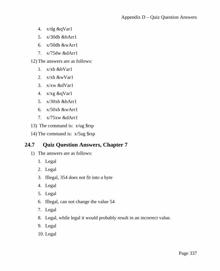
Appendix D – Quiz Question Answers
4. x/dg &qVar1
5. x/30db &bArr1
6. x/50dh &wArr1
7. x/75dw &dArr1
12) The answers are as follows:
1. x/xb &bVar1
2. x/xh &wVar1
3. x/xw &dVar1
4. x/xg &qVar1
5. x/30xb &bArr1
6. x/50xh &wArr1
7. x/75xw &dArr1
13) The command is: x/ug $rsp
14) The command is: x/5ug $rsp
24.7 Quiz Question Answers, Chapter 7
1) The answers are as follows:
1. Legal
2. Legal
3. Illegal, 354 does not fit into a byte
4. Legal
5. Legal
6. Illegal, can not change the value 54
7. Legal
8. Legal, while legal it would probably result in an incorrect value.
9. Legal
10. Legal
Page 337

Appendix D – Quiz Question Answers
11. Legal, while legal it would probably result in an incorrect value.
12. Illegal, can not move memory to memory
13. Illegal, can not move memory to memory
14. Legal
15. Legal
16. Legal
2) The answers are as follows:
1. Copies the byte value at bVar1 into the rsi register treating as an unsignedvalue thus setting the upper 56 bytes to 0.
2. Copies the byte value at bVar1 into the rsi register treating as a signed value,thus sign extending the upper 56-bits (1's for negative, 0's for positive).
3) The answers are as follows:
1. mov ah, 0
2. cbw
4) The answers are as follows:
1. movzx eax, ax
2. cwde
5) The answers are as follows:
1. mov dx, 0
2. cwd
6) The cwd instruction only converts the signed value in ax into a sign value indx:ax (and nothing else). The movsx instruction copies the word sourceoperand into the double-word destination operand.
7) On the first instruction, the destination operand size can be determined from thesource operand (as double-word). On the second instruction, the destinationoperand size must be explicitly specified since the source operand, value of 1,does not have an inherent size associated with it.
8) The answers are as follows (grouped in sets of 4 for clarity):
1. rax = 0x0000 0000 0000 0009
Page 338

Appendix D – Quiz Question Answers
2. rbx = 0x0000 0000 0000 000B
9) The answers are as follows (grouped in sets of 4 for clarity):
1. rax = 0x0000 0000 0000 0007
2. rbx = 0x0000 0000 0000 0002
10) The answers are as follows (grouped in sets of 4 for clarity):
1. rax = 0x0000 0000 0000 0009
2. rbx = 0x0000 0000 FFFF FFF9
11) The answers are as follows (grouped in sets of 4 for clarity):
1. rax = 0x0000 0000 0000 000C
2. rdx = 0x0000 0000 0000 0000
12) The answers are as follows (grouped in sets of 4 for clarity):
1. rax = 0x0000 0000 0000 0001
2. rdx = 0x0000 0000 0000 0002
13) The answers are as follows (grouped in sets of 4 for clarity):
1. rax = 0x0000 0000 0000 0002
2. rdx = 0x0000 0000 0000 0003
14) The answers are as follows:
1. The destination operand can not be an immediate value (42).
2. An immediate operand is not allowed since the size/type can not bedetermined.
3. The mov instruction does not allow a memory to memory operation.
4. An address requires 64-bits which will not fit into the ax register.
15) The idiv instruction will divide by edx:eax and edx was not set.
16) The operands for the divide a signed (-500), but an unsigned divide is used.
17) The word divide used will place the result in the dx:ax registers, but the eaxregister is used to obtain the result.
18) The three operand multiple is only allowed for a limited set of signedmultiplication operations.
Page 339

Appendix D – Quiz Question Answers
24.8 Quiz Question Answers, Chapter 8
1) The first instruction places the value from qVar1 into the rdx register. Thesecond instruction places the address of qVar1 into the rdx register.
2) The answers are as follows:
1. Immediate
2. Memory
3. Immediate
4. Illegal, destination operand can not be an immediate value
5. Register
6. Memory
7. Memory
8. Illegal, source and destination operands not the same size.
3) The answers are as follows (grouped in sets of 4 for clarity):
1. eax = 0x0000 000A
4) The answers are as follows (grouped in sets of 4 for clarity):
1. eax = 0x0000 0003
2. edx = 0x0000 0002
5) The answers are as follows (grouped in sets of 4 for clarity):
1. eax = 0x0000 0009
2. ebx = 0x0000 0002
3. rcx = 0x0000 0000 0000 0000
4. rsi = 0x0000 0000 0000 000C
6) The answers are as follows (grouped in sets of 4 for clarity):
1. rax = 0x0000 0010
2. rcx = 0x0000 0000 0000 0000
3. edx = 0x0000 0000
4. rsi = 0x0000 0000 0000 0004
Page 340

Appendix D – Quiz Question Answers
7) The answers are as follows (grouped in sets of 4 for clarity):
1. eax = 0x0000 0002
2. rcx = 0x0000 0000 0000 0000
3. edx = 0x0000 0005
4. rsi = 0x0000 0000 0000 0003
8) The answers are as follows (grouped in sets of 4 for clarity):
1. eax = 0x0000 0018
2. edx = 0x0000 0000
3. rcx = 0x0000 0000 0000 0000
4. rsi = 0x0000 0000 0000 0005
24.9 Quiz Question Answers, Chapter 9
1) The rsp register.
2) First, rsp = rsp - 8 and then rax register is copied to [rsp] (in that order).
3) 8 bytes.
4) The answers are as follows (grouped in sets of 4 for clarity):
1. r10 = 0x0000 0000 0000 0003
2. r11 = 0x0000 0000 0000 0002
3. r12 = 0x0000 0000 0000 0001
5) The array is reversed in memory.
6) Memory is used more efficiently.
24.10 Quiz Question Answers, Chapter 10
1) An unambiguous, ordered sequence of steps involved in solving a problem.
2) The answer is as follows:
1. Understand the Problem
2. Create the Algorithm
3. Implement the Program
Page 341

Appendix D – Quiz Question Answers
4. Test/Debug the Program
3) No, the step are applicable to any language or complex problem (even beyondprogramming).
4) An assemble-time error.
5) An assemble-time error.
6) An assemble-time error.
7) A run-time error.
24.11 Quiz Question Answers, Chapter 11
1) At the top (above the data, BSS, and text sections).
2) Once for each time the macro is invoked.
3) The %% will ensure that a unique label name is generated each time the macro isused.
4) If the %% is omitted on a label, the label will be copied, as is, and thus appear tobe duplicated.
5) Yes. This might be used to exit a macro to an error handling code block (notwithin the macro).
6) The macro argument substitution occurs at assemble-time.
24.12 Quiz Question Answers, Chapter 12
1) Linkage and Argument Transmission.
2) The call and the ret instructions.
3) Call-by-value.
4) Call-by-reference.
5) Once, regardless of how many times it is called.
6) The current rip is placed on the stack and the rip is changed to the address ofcalled function.
7) Save and restore the contents of the callee preserved registers.
8) In: rdi, rsi, rdx, rcx, r8, and r9.
9) In: edi, esi, edx, ecx, r8d, and r9d.
Page 342

Appendix D – Quiz Question Answers
10) That a function may change the value in the register without needing to save andrestore it.
11) Two of: rax, rcx, rdx, rsi, rdi, r8, r9, r10, and r11.
12) Call frame, function call frame, or activation record.
13) A leaf function does not call other functions.
14) Clear the passed arguments off the stack.
15) Twenty-four (24) since three arguments at 8 bytes each (8 x 3).
16) The offset is [rbp+16] regardless of which saved registers are pushed.
17) Available memory.
18) Call-by-reference.
19) The 7th argument is at [rbp+16] and the 8th argument is at [rbp+24].
20) Memory efficiency since stack dynamic local variables only use memory whenneeded (when the function is being executed).
24.13 Quiz Question Answers, Chapter 13
1) The rax register.
2) The operating system.
3) The call code is SYS_write (1). The 1st argument is rdi is the output locationSTDOUT, the 2nd argument is rsi is the starting address of the characters tooutput, and the 3rd argument in rdx is the number of characters to write.
4) It is unknown how many characters will be entered.
5) The rax register will contain the file descriptor.
6) The rax register will contain an error code.
7) In: rdi, rsi, rdx, r10, r8, and r9.
24.14 Quiz Question Answers, Chapter 14
1) The statement is: extern func1, func2
2) The statement is: extern func1, func2
3) The assembler will generate an error.
Page 343

Appendix D – Quiz Question Answers
4) Link-time.
5) The linker will generate an unsatisfied external reference error.
6) Yes. However, in the debugger, the code would not be displayed.
24.15 Quiz Question Answers, Chapter 15
1) The buffer overflow exploit is typically called stack smashing.
2) The C function does not check the array bounds of the input arguments.
3) Yes.
4) Typing a very large number of characters when input is requested and, if theprogram crashes.
5) A series of nop instructions designed to make the target of a buffer overflowexploit easier to hit.
6) Many possible answers. Delete a file, open a network connection, kill a process,etc.
7) Use of canaries, implementation of Data Execution Prevention (DEP), and use ofData Address Space Layout Randomization.
24.16 Quiz Question Answers, Chapter 16
1) The operating system. Specifically, the loader.
2) The program being executed.
3) The name of the executable file.
4) The argc refers to argument count and argv refers to the argument vector(starting address of the table of addresses for the string representing eachargument).
5) In the rdi register.
6) In the rsi register.
7) The spaces are removed by the operating system so the program does not have todo anything.
8) No. The program is required to check and determine if that is an error.
Page 344

Appendix D – Quiz Question Answers
24.17 Quiz Question Answers, Chapter 17
1) The end of line character for Linux is linefeed (LF) and the end of line characterfor Windows is carriage return, line feed (CR, LF).
2) Store a subset of the information for quick access.
3) They are in the language I/O library functions (i.e., cout, cin, etc.).
4) Simplify the programming.
5) I/O performance improvement.
6) The system service functions require a specific number of characters to readwhich is not known ahead of time for “one line” of text.
7) Keeps a subset of the information at the next higher level in the hierarchy (whichis faster than the next lower level).
8) Reduces the overhead associated bus contention and memory latency forexcessive system reads.
9) The variable values must be retained between function calls.
10) The end of file must be inferred from the number of characters actually read.
11) Many reasons possible, including file being deleted in another Window after theopen or the drive (USB) being removed after the open.
12) The actual number of characters read will be 0 which must be check explicitly.
13) To ensure the passed line buffer array is not overwritten.
14) By initializing the variables to indicate that all buffer characters have been read.
24.18 Quiz Question Answers, Chapter 18
1) The registers are: xmm0, xmm1, xmm2, . . ., xmm15.
2) Single precision is 32-bit and double precision is 64-bits.
3) Cumulative rounding error associated with the inexact representation of 0.1 inbinary.
4) Float functions return the value in xmm0.
5) None of the floating point registers are preserved.
Page 345

Appendix D – Quiz Question Answers
24.19 Quiz Question Answers, Chapter 19
1) Concurrency implies multiple different (not necessarily related) processessimultaneously making progress. Parallel processing implies that processes areexecuting simultaneously.
2) Distributed computing and multiprocessing.
3) On different computers connected via a network.
4) Many possible answers, including Folding@Home and SETI@Home. AnInternet search can provide a more complete listing.
5) On different cores in the CPU.
6) Distributed computing allows a very large number of compute nodes butrequires communications over a network which has inherent communicationdelays.
7) Multiprocessing allows very fast communications between processes via sharedmemory but supports only a limited amount of simultaneous executing threadsrelated to the number of cores available.
8) Multiple threads simultaneously writing to a shared variable with no control orcoordination.
9) No. No problem exists since the variable is not being changed.
10) Yes. Since the variable is being changed, one thread may alter the value afterthe other has obtained the value.
24.20 Quiz Question Answers, Chapter 20
1) The operating system is responsible for managing the resources. The resourcesinclude CPU cores, primary memory, secondary storage, display screen,keyboard, and mouse.
2) An event that alters the sequence of instructions executed by a processor.
3) An interrupt that is caused by the current process and needs attention of thekernel.
4) And ISR is an Interrupt Service Routine which is executed when an interruptoccurs to service (perform required actions) that interrupt.
5) Interrupt Descriptor Table (IDT) which contains the addresses of the InterruptService Routines (ISRs) and the gate information.
Page 346
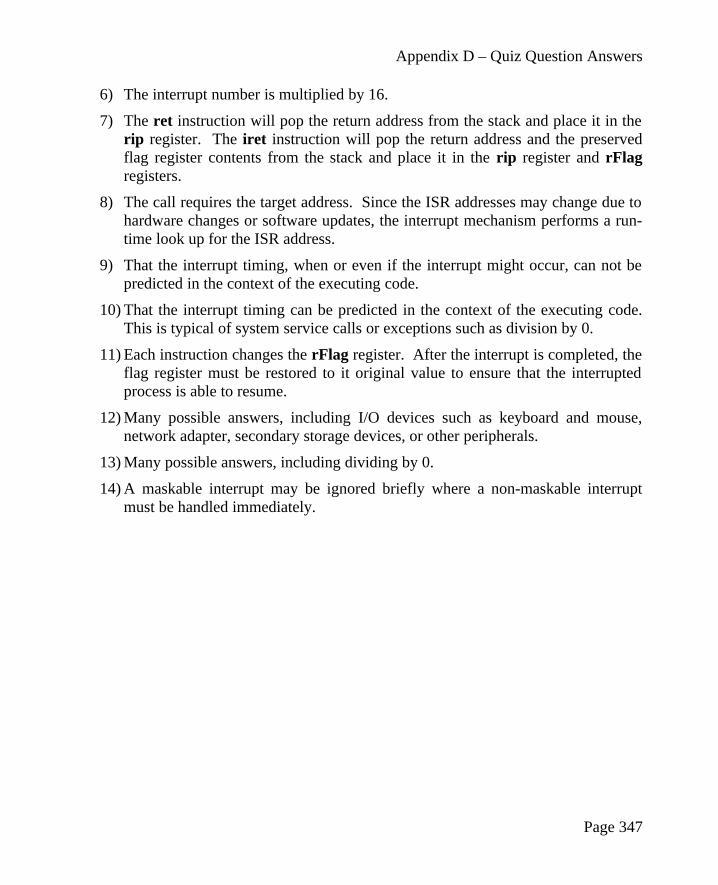
Appendix D – Quiz Question Answers
6) The interrupt number is multiplied by 16.
7) The ret instruction will pop the return address from the stack and place it in therip register. The iret instruction will pop the return address and the preservedflag register contents from the stack and place it in the rip register and rFlagregisters.
8) The call requires the target address. Since the ISR addresses may change due tohardware changes or software updates, the interrupt mechanism performs a run-time look up for the ISR address.
9) That the interrupt timing, when or even if the interrupt might occur, can not bepredicted in the context of the executing code.
10) That the interrupt timing can be predicted in the context of the executing code.This is typical of system service calls or exceptions such as division by 0.
11) Each instruction changes the rFlag register. After the interrupt is completed, theflag register must be restored to it original value to ensure that the interruptedprocess is able to resume.
12) Many possible answers, including I/O devices such as keyboard and mouse,network adapter, secondary storage devices, or other peripherals.
13) Many possible answers, including dividing by 0.
14) A maskable interrupt may be ignored briefly where a non-maskable interruptmust be handled immediately.
Page 347

Appendix D – Quiz Question Answers
Page 348

25.0 Alphabetical Index
0x............................................................7249..........................................................290activation record...................................178add with carry.........................................83Addresses vs Values.......................75, 129Addressing Modes................................129American Standard Code for Information Interchange.............................................28Architecture Overview.............................7argc.......................................................248Argument Count...................................249Argument Transmission.......................175Argument Vector Table........................249argv.......................................................248Arithmetic Logic Unit..............................9ASCII......................................................28Assemble and Link...............................231Assemble Commands.............................43Assemble/Link Script.............................50Assemble/Link/Load Overview..............41Assembler...............................................43Assembler Directives..............................47Assembler Error....................................161Assembly Main.....................................228assembly source file...............................33Asynchronous Interrupts......................298
automatics.............................................172base address..........................................132Base Pointer Register.............................12Basic System Services..........................325biased exponent......................................25BSS.........................................................17BSS Section............................................35buffer....................................................258Buffering Algorithm.............................259byte addressable..............................15, 132cache memory...........................................9Cache Memory.................................14, 19call code................................................197call frame..............................................178Call Frame............................................178call-by-reference...................................175call-by-value.........................................175callee.....................................................175Callee............................................181, 184caller.....................................................175Caller............................................181, 183Calling Convention...............................175Calling System Services.......................197Central Processing Unit............................9character.................................................28code generation.......................................47
Page 349
Index

Alphabetical Index
Code Injection......................................242Code Injection Protections...................243Code to Inject.......................................239Command Line Arguments..................247Comments...............................................33Compile, Assemble, and Link..............234concurrency..........................................289Conditional Control Instructions..........112Console Input........................................203Console Output.....................................199constant expression.................................46Conversion Instructions..........................76CPU register...........................................10Data Address Space Layout Randomization......................................244Data Execution Prevention...................244Data Movement..............................73, 266Data representation.................................21Data Section............................................34Data Stack Smashing Protector (or Canaries)...............................................244db............................................................34dd............................................................35DDD Configuration Settings..................57DDD Debugger.......................................55DDD/GDB Commands Summary..........62DDD/GDB Commands, Examples.........64ddq..........................................................35Debugger................................................52Debugger Command, next....................172Debugger Command, step....................172Debugger Commands...........................172Debugger Commands File (interactive). 65Debugger Commands File (non-interactive)...........................................66p.Debugging Macros...............................169Defining Constants.................................34dereferencing........................................130
Destination operand........................72, 309Direct Memory Addressing..................258Displaying Register Contents.................60Displaying Stack Contents.....................65distributed computing...........................290Distributed Computing.........................290distributed processing...........................290DMA.....................................................258dq............................................................35dt.............................................................35dw...........................................................34dynamic linking......................................50Dynamic Linking....................................50epilogue................................................175Error Codes...........................................328Error Terminology................................161Example Program...................................37Example Program, Absolute Value......285Example Program, List Summation.....133Example Program, Pyramid Areas and Volumes................................................135Example Program, Sum and Average. .283Example, C++ Main / Assembly Function..............................................................232Example, Console Input.......................204Example, Console Output.....................200Example, File Read..............................217Example, File Write..............................212Example, Statistical Function 1 (leaf). .181Example, Statistical Function2 (non-leaf)..............................................................183Example, Sum and Average.................228Exceptions............................................299Executing Programs................................58extern....................................................227Extern Statement..................................227external reference...................................48File Control Block................................208
Page 350

Alphabetical Index
file descriptor................199, 203, 208, 210File Modes............................................327File Open..............................................209File Open Operations............................208File Open/Create...................................210File Operations Examples.....................212File Read...............................................211File Write..............................................211First Pass.................................................46Flag Register...........................................12Floating Point Addition........................270Floating Point Arithmetic Instructions. 270Floating Point Calling Conventions.....283Floating Point Comparison...................280Floating Point Control Instructions......279Floating point destination register operand........................................................72, 309Floating Point Division.........................275Floating Point Instructions...................265Floating Point Multiplication...............273Floating Point Registers.......................266Floating Point Square Root..................277Floating Point Subtraction....................272Floating Point Values...........................265Floating-point Representation................24forward reference....................................46Function Declaration............................173Function Source....................................230Functions..............................................171General Purpose Registers......................10GPRs.......................................................10Hardware Interrupt...............................299heap.................................................17, 148I/O Buffering........................................257IEEE 32-bit Representation....................25IEEE 64-bit Representation....................27IEEE 754 32-bit floating-point standard 24IF statement..........................................112
Immediate Mode Addressing...............130Immediate value.............................72, 309index.....................................................132indirection.............................................130input buffer...........................................258Input/Output Buffering.........................257Instruction Pointer Register....................12Instruction Set Overview........................71Integer / Floating Point Conversion Instructions...........................................268Integer Arithmetic Instructions...............80integer numbers......................................21Interfacing with a High-Level Language..............................................................232Interrupt Categories..............................299Interrupt Classification.........................298Interrupt Processing..............................302Interrupt Service Routine (ISR)............302Interrupt Timing...................................298Interrupt Types.....................................300Interrupt Types and Levels...................300Interrupts...............................................297Iteration.................................................118Jump Out Of Range..............................115jump out-of-range.................................115Jump to ISR..........................................303Labels...................................................111leaf function..........................................178Least Significant Byte............................15light-weight process..............................291Linkage.................................................174Linker.....................................................47Linking Multiple Files............................48Linking Process......................................48list file.....................................................43List File...................................................43List Summation....................................133little-endian..........................15p., 151, 241
Page 351

Alphabetical Index
Loader.....................................................52Logic Error...........................................162logical AND operation.........................106logical NOT operation..........................106logical OR operation.............................106logical XOR operation..........................106machine language...............17, 43, 45, 240Macro Definition..................................166Macros..................................................165Main Memory.........................................15memory hierarchy...........................17, 257Memory Hierarchy.................................17memory layout................................16, 148Memory Mode Addressing...................130Most Significant Byte.............................15Multi-Line Macros................................166Multi-user Operating System...............297Multiple Source Files...........................227multiprocessing.....................................290Multiprocessing....................................290NaN.................................................27, 279Narrowing conversions...........................76Narrowing Conversions..........................76Newline Character................................198Next / Step..............................................60nexti......................................................169non-volatile memory................................8NOP slide..............................................243normalized scientific notation................25not a number...................................27, 279Not a Number (NaN)..............................27Notation................................................309Notational Conventions..........................71Numeric Values......................................33object file................................................43Obtaining ISR Address.........................302offset.....................................................132Operand Notation...........................72, 309
operands..................................................71operation.................................................71ordered floating point comparisons......279parallel processing................................289Parallel Processing................................289Parameter Passing.................................176Parsing Command Line Arguments.....247pop operation........................................145POSIX Threads.....................................291preserved register..................................177Primary Storage..................................7, 19Privilege Levels....................................300Process Stack........................................145Processing Steps...................................302processor registers....................................9Program Development..........................155Program Format......................................33prologue................................................175push operation......................................145race condition.......................................291Race Conditions....................................292Random Access Memory (RAM).............7RBP.........................................................12Red Zone..............................................180register....................................................10Register Mode Addressing...................130Register operand.............................72, 309Register Usage......................................177resb.........................................................36resd.........................................................36resdq.......................................................36resq.........................................................36Resumption...........................................304resw.........................................................36Return Codes........................................325rFlags......................................................12RIP..........................................................12RSP.........................................................12
Page 352

Alphabetical Index
Run / Continue........................................60Run-time Error......................................161saved register........................................177Second Pass............................................46secondary storage.....................................8Secondary Storage..............................7, 19section .bss..............................................35section .data............................................34section .text.............................................36segment fault........................................239Setting Breakpoints................................57short-jump.............................................115sign extension.......................................108sign-extend.............................................78signed......................................................21Signed Conversions................................78Single Instruction Multiple Data............13Single-Line Macros..............................165SNaN....................................................279Software Interrupts...............................300source file...............................................43Source operand...............................72, 309stack buffer overflow............................237Stack Buffer Overflow.........................237Stack Dynamic Local Variables...........172Stack Example......................................151stack frame............................................178Stack Implementation...........................147Stack Instructions.................................146Stack Layout.........................................148Stack Operations...................................149Stack Pointer Register............................12stack smashing......................................237Stack-Based Local Variables................187
Standard Calling Convention...............173Starting DDD..........................................55stepi.......................................................169string.......................................................29Summary...............................................190Suspension............................................302Suspension Execute ISR.......................303Suspension Interrupt Processing Summary..............................................................304symbol table............................................46Synchronous Interrupts.........................298system call............................................197System Services....................................197Text Section............................................36thread....................................................291Tool Chain..............................................41Two-Pass Assembler..............................45two's complement................................22p.Unconditional Control Instructions......112Understanding a Stack Buffer Overflow..............................................................238Unicode...................................................29uninitialized data............................17, 148unordered floating point comparisons. .279unsafe function.....................................239unsigned..................................................21Unsigned Conversions............................77Updated Linking Instructions...............171Using a Macro......................................166volatile memory........................................8Why Buffer...........................................257Widening conversions............................76Widening Conversions...........................76%define.................................................165
Page 353


