8 Connections 8.1 Serial Link and Supply Connector Pin Arrangement Serial link: 25pin, female subminiature (SUB D) connector, type HE50 NF-C 93.425. 0 10 20 014 30 015 40 016 50 017 60 Q9 OW ~ 70 80 QO 90 021 100 Q2 110 023 120 024 130 025 0 Pin DESIGNATION Number FUNCTION 1 -11’ Chassis ground 2 TXD RS 232 Transmission 3 RXD RS 232 Reception 4 +TD RS 422/485 Transmission 5 -TD RS 422/485 Transmission 6 +RD RS 422/485 Reception 7 ov RS 232/RS 422 Common 8 COM Common for multipoint address and Adjust (pins 12, 14-l 7, 24) 9 +REC Isolated current loop reception 10 -REC Isolated current loop reception 11 Reserved 12 Reserved 13 Reserved 14 80 Terminal address in multipoint mode (binary 1) 15 Bl Terminal address in multipoint mode (binary 2) 16 B2 Terminal address in multipoint mode (binary 4) 17 83 Terminal address in multipoint mode (binary 8) 18 -RD RS 422J485 Reception 19 Reserved 20 +TRA Isolated current loop transmission 21 -TRA Isolated current loop transmission 22 Reserved 23 Reserved 24 PAR Multipoint address parity 25 Reserved
Transcript
8 Connections
8.1 Serial Link and Supply Connector Pin Arrangement
Serial link: 25pin, female subminiature (SUB D) connector, type HE50 NF-C 93.425.
0
10 20
014
30 015
40 016
50 017
60 Q9
OW
~
70
80 QO
90 021
100 Q2
110 023
120 024
130 025
0
Pin DESIGNATION Number
FUNCTION
1 -11’ Chassis ground
2 TXD RS 232 Transmission
3 RXD RS 232 Reception
4 +TD RS 422/485 Transmission
5 -TD RS 422/485 Transmission
6 +RD RS 422/485 Reception
7 ov RS 232/RS 422 Common
8 COM Common for multipoint address and Adjust (pins 12, 14-l 7, 24)
9 +REC Isolated current loop reception
10 -REC Isolated current loop reception
11 Reserved
12 Reserved
13 Reserved
14 80 Terminal address in multipoint mode (binary 1)
15 Bl Terminal address in multipoint mode (binary 2)
16 B2 Terminal address in multipoint mode (binary 4)
17 83 Terminal address in multipoint mode (binary 8)
18 -RD RS 422J485 Reception
19 Reserved
20 +TRA Isolated current loop transmission
21 -TRA Isolated current loop transmission
22 Reserved
23 Reserved
24 PAR Multipoint address parity
25 Reserved
8 Connections
Serial Link and Supply Connector Pin Arrangement
Power Supply + El _
4-
24V G
ov c
Chassis ground
8 Connections
8.2 Connecting a CRT or TSX T407 Terminal -
l Connecting a CRT Terminal
XBT-A CRT Terminal
The connection between the CRT terminal and the XBT-A uses a 2.50 meter
XBT Z 905 cable connected to the “LINE” input to the CRT terminal and to the “Serial” port of the XBT-A terminal.
The transmission parameters must be set first. To change the settings on the XBT-A terminal, refer to sub-section 4.5: Configuration, page 24.
l Connecting a TSX T 407 terminal
XBT-A TSX T 407
-
The connection between the TSX T407 programming terminal and the
XBT-A uses a 2.50 meter XBT Z 905 cable. - connected to the “Printer” port on the TSX T407,
- connected to the “Serial” port on the XBT-A, - connect the XBT Z 905 cable with the end showing the reference number
to the XBT-A.
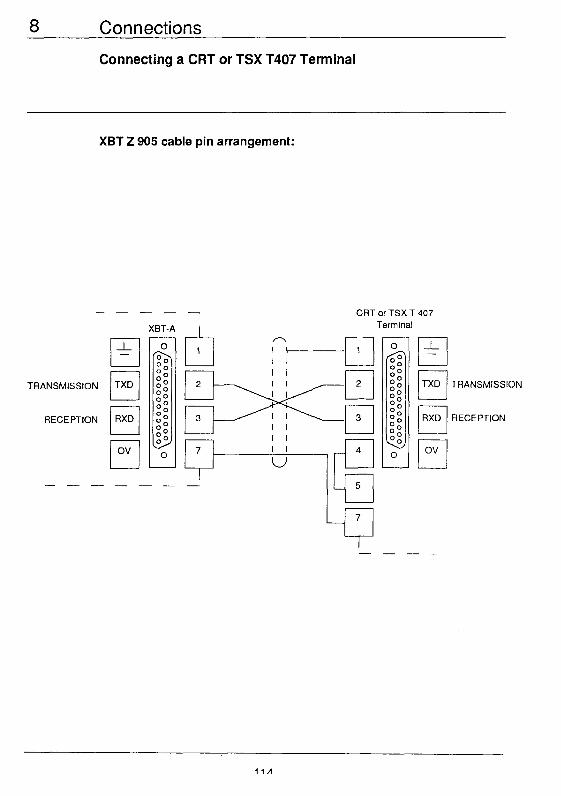
8 Connections
Connecting a CRT or TSX T407 Terminal
XBT 2 905 cable pin arrangement:
----_
XBT-A I CRT or TSX T 407
Terminal
TRANSMISSION
RECEPTION
A
1 I-1 I I I I
h
cl
2 I I 2 I I cl
3 I I cl
3 I I
4
E 5
-L I I -
r-l TXD TRANSMISSION L.--L
r-l RXD RECEPTION
lid
8 Connections
8.3 Connecting a PUPS Microcomputer
The XBT-A terminal can be connected to a PUPS microcomputer for performing operations on the application (creation, storage, modification or
transfer) in conjuction with XBTL-100 software. The characteristics of the data link (RS 232C) cannot be changed. Connection is made to the serial port of the microcomputer (COM 1).
. The following cables are available:
PUPS Cable Serial port
Connector Ref. No.
g-pin male XBTZ915
25.pin male XBTZ905
25-pin female XBTZ9052
l products available since July 1988
Version
21’
21’
11
Length
2.50 m
2.50 m
2.50 m
8 Connections
Connecting a PUPS Microcomputer
XBTZ915 cable pin arrangement: ----a
XBT-A I
I---- , g-pin serial port
TRANSMISSION
RECEPTION
I I I I q 2 I I I I
3 I I I I 0
3
I I 7
I I I 8
r-l FITS
q CTS
cl DSR
XBTZ905 and XBTZ9052 cable pin arrangement:
RECEPTION
TRANSMISSION
TRANSMISSION
RECEPTION
--- XBT-A
--
---_ t 2.5pin serial port
u n
TRANSMISSION
RECEPTION
L-l DSR
cl DTR
Connections
8.4 Connecting a TSX17-20 Micro-PLC W
The XBT-A terminal connects to the programming port of a TSX 17-20
Micro-PLC via a 2.5 meter XBTZ 917 cable.
Note: RS 485 is an extension of the RS 422 standard (“4-wire” differential
transmission) that loops the transmitter back to the receiver in the XBT-A.
Distance (m) I
1OM SPEED (BAUD)
XBT-A
TSX 17-20
Programming Port
8 Connections
Connecting a TSX17-20 Micro-PLC
------ ----- r--------- TSX 17-20
XBT-A
XBT 2 917 cable pin arrangement.
(PROGRAMMING
PORT)
0
00 00 00 00 OO 00
-
00 00 00 00 00 go 0 R
<
I I
6 o- (I 12
------------J
0 0
00 00 00 ! 0 00 00 00 00
0
8 Connections
8.5 Connecting TSX 27/47 PLCs
The XBT-A terminal connects to the programming port of a TSX 17-20
Micro-PLC via a 2.5 meter XBTZ 902 cable.
The supply for the current loop is provided by the TSX 27/47 (ACTIVE). Current limiting is ensured by the XBT-A (PASSIVE PROTECTED). Note: the programming port of TSX 27 and TSX 47100 PLCs is not isolated.
When using these PLCs, when the distance between the XBT-A and the TSX 27/47 is more than 3 meters, a XBT Z 9011/l 2 isolating device must be used between the two units (further details on the XBT Z 90.. in this section).
Distance (m) +
1 OOOm
loom
15m
(BAUD)
XBT-A TSX 7
8 Connections
Connecting TSX 27/47 PLCs
XBT 2 902 cable pin arrangement.
XBT-A
------__ 1
r_____-___--___
TSX 27147
(PROGRAMMING
PORT)
I I 8 ,‘I 12
-----__-----__J
iission
ti
a ov
----cl 5-IL T
L___________-___
8 Connections
Connecting TSX 27147 PLCs
Isolating device for TSX 27 and TSX 47100
If the distance betweeh the XBT-A terminal and the PLC is more than 3
meters, the XBT Z 901 l/12 isolating device should be used. The distance
between the PLC and the XBT Z 90.. must be less than 5 meters (connected by two shielded twisted pairs of not less that 0.6 mm2 (AWG 22)
gauge). The distance between the XBT Z 901 l/12 and the XBT-A terminal can be as much as 1000 meters (connected by two shielded twisted pairs of not less
that 0.6 mm2 (AWG 22) gauge).
131
8 Connections
Connecting TSX 27/47 PLCs
TOP VIEW
XBT-A XBTZ 901 l/l2 TSX 47
2 1000 m.
---_----
R &+ ,2y(Progrzngpon)
Transmission I-I\ : L-_-_---1
Mechanical characteristics:
- XBT Z9011: symetrical rail mount
XBT Z9012: asymetrical rail mount Dimensions:
Length
Width
Depth
:96mm
:27mm
:42mm
Transmission/Reception indication IS provided by LEDs.
8 Connections
8.6 Connecting a Serial Communication Module sss+
0 Current loop connection
The power supply to the current loop is provided by the module (ACTIVE).
The XBT-A ensures current limiting (PASSIVE PROTECTED). The maximum data link distance is 1000 meters (connected by two shielded
twisted pairs of not less that 0.6 mm*(AWG 22) gauge). When used with TSX Series 7 PLCs, the XBT-A connects to the TSX SCM
20.. module via a 2.5 meter XBT Z 906 cable.
Distance 120 mA CURRENT! Cm)
1OOOm
1OOm
15m
(BAUD)
XBT-A
I-
XBT Z 906
TSX-47167167
XBT Z 906 cable connection: Ref. no. end to XBT-A.
rnn
8 Connections
Connecting a Serial Communication Module
XBT 2 906 cable pin arrangement:
---
XBT- A
-
--1
I + 9
Reception a 10 -
Transmission
____ Lz-. TransmI-,,:_rent ,oop ]
SUPPlY) 1 II
- -- i c___--_-____-__-
8 Connections
Connecting a Serial Communication Module
RS 232 C connection:
The transmission parameters must be set. To do this, refer to sub-section
4.5.2, Configuration, page 26. The maximum data link distance is 15 meters and connection via by two
shielded twisted pairs of not less that 0.6 mm2 (AWG 22) gauge). When used with TSX Series 7 PLCs, the XBT-A connects to the TSX SCM
20.. module via a 2.5 meter XBT Z 905 cable.
Distance
(m)
t
1 OOm
15m
XBT-A TSX47i67/07
1
1 10K 1 OO’K SPEED
(BAUD)
XBT 2 905
XBT Z 905 cable connection: Ref. no. end to XBT-A.
125
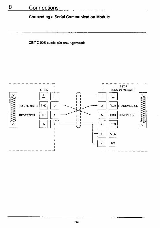
Connections
Connecting a Serial Communication Module
XBT 2 905 cable pin arrangement:
XBT-A
RECEPTION q RXD
A
1 ‘c-----i I I
k
157 I I
2 I I I I 0
3 I I I I
r-h
TSX 7 (SCM 20 MODULE)
c _L -
r-l RTS i?-
cl CTS
I O” I -
8 Connections
Connecting a Serial Communication Module
RS 422 connection:
The transmission parameters must be set. To do this, refer to sub-section
4.52 Configuration, page 26.
This standard defines a differential transmission mode. This “4-wire” data
link enables operation in Full Duplex mode.
Distance
(m)
10 M Baud
Connect via by two shielded twisted pairs of not less that 0.6 mm’(AWG 22)
gauge).
137
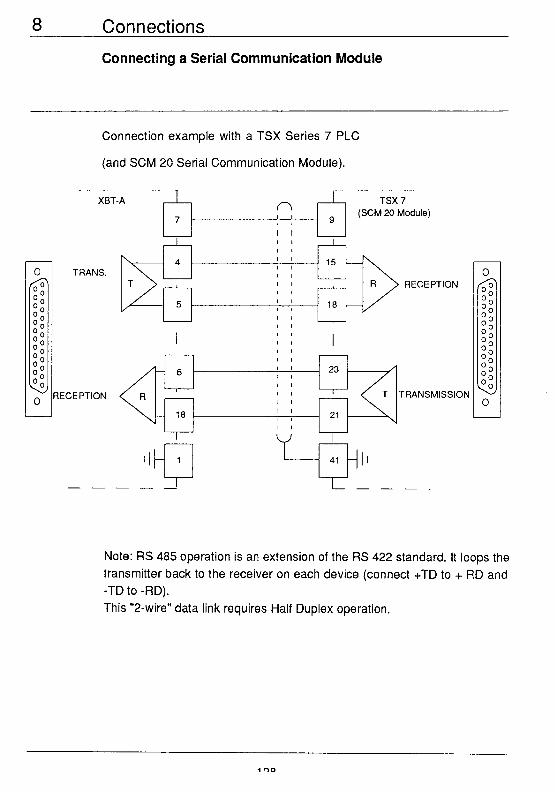
Connections
Connecting a Serial Communication Module
Connection example with a TSX Series 7 PLC
(and SCM 20 Serial Communication Module).
---- XBT-A
r-5 A
T TRANSMISSION
Note: RS 485 operation is an extension of the RS 422 standard. It loops the
transmitter back to the receiver on each device (connect +TD to + RD and -TD to -RD).
This “2-wire” data link requires Half Duplex operation.
8 Connections
8.7 Multipoint Connection
l Serial multipoint
XBT-A terminals operate in ASCII, PROTECTED PASSING CURRENT
LOOP MODE. The line power supply is provided by an external source or by the Serial
Communication Module (ACTIVE).
All XBT-A terminals must be connected in series.
Current limiting is ensured by XBT-A terminals (PASSIVE PROTECTED).
XBT-A terminals must be addressed (coded) by wiring in the serial
connector. Refer to sub-section 6.8, Multipoint Operation, page 96.
13Q
Connections
Multipoint Connection
Connection example for a TSX Series 7 PLC and an SCM 20 module. ---------
XBT- A
Reception I I I I I I
- 20
Reef
- 9
1 Reception
10 -
-
20 --
I
21 -.
- I I
- ---------I
XBT- A
Reception
Transmission
I___-_ ------- -__
inn
8 Connections
Multipoint Connection
. Multipoint parallel
XBT-A TERMINALS OPERATE IN ASCII MODE WITH BLOCKED
CURRENT LOOP
The line power supply is provided by an external source or by the Serial
Communication Module (ACTIVE).
All XBT-A terminals must be connected in parallel. XBT-A terminals must be addressed (coded) by wiring in the serial connector.
Refer to sub-section 6.8, Multipoint Operation, page 96.
Connection example for a TSX Series 7 PLC and an SCM 20 module:
-- -- 1
XBT- A n
__---- _----
XBT- A
+-t-I ov 7
- - I
- _------__
Transmission k-- 11 Q-----h Reception
fw
l-___---
8 Connections
Multipoint Connection
. Multipoint parallel
XBT-A TERMINALS OPERATE IN ASCII RS 422 MODE - All Slave receive lines are wired in parallel to the Master transmission line. - All Slave transmit lines are wired in parallel to the Master reception line.-
The number of Slave stations is restricted to 10. XBT-A terminals must be addressed (coded) by wiring in the serial
connector. Refer to sub-section, 6.8 Multipoint Operation, page 96.
--- XBT-A
- _ - - BLOCK DIAGRAM TSX 7
A 9 (SCM 20 module)
-RD 1 -7 --__ t
TRANSMISSION RECEPTION
OTHER TERMINALS
8 Connections
Multipoint Connection
The length of passive drops must not exceed 10 meters.
The total line length must not exceed 1200 meters.
To install this type of data link, line adapters may be required.
For further information refer to the TSX SCM Installation Manual (Ref. No. TSX D43 724).
Note: RS 485 operation is possible by looping the receiver back to the transmitter (connect + TD to + RD and - TD to - RD) on all XBT-A terminals
and on the 2-wire master logic.
All devices connected in RS 485 mode must operate in Half Duplex mode.
Address coding limits the number of devices to a maximum of 15.
Connections
8.8 Connecting the Test Plugs
In Configuration mode, selecting the Tests procedure enables tests to be performed to check for correct operation of XBT-A terminal sub-units,
especially the physical data links and their addresses.
Before starting a test of the selected data link (RS 232, 20MA CL, RS 422) it is necessary to fit the appropriate test plug on the serial link connector of
the XBT-A terminal. The test is started by pressing the I[DEL)) key.