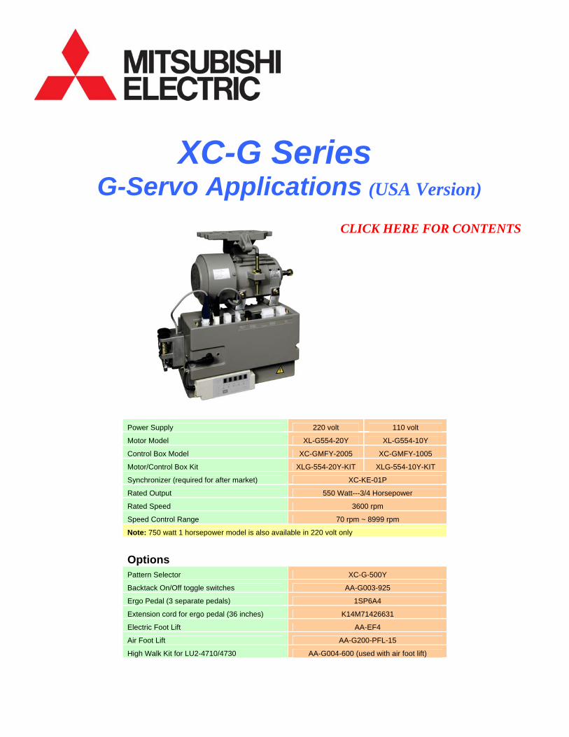
XC-G Series G-Servo Applications (USA Version) CLICK HERE FOR CONTENTS Power Supply 220 volt 110 volt Motor Model XL-G554-20Y XL-G554-10Y Control Box Model XC-GMFY-2005 XC-GMFY-1005 Motor/Control Box Kit XLG-554-20Y-KIT XLG-554-10Y-KIT Synchronizer (required for after market) XC-KE-01P Rated Output 550 Watt---3/4 Horsepower Rated Speed 3600 rpm Speed Control Range 70 rpm ~ 8999 rpm Note: 750 watt 1 horsepower model is also available in 220 volt only Options Pattern Selector XC-G-500Y Backtack On/Off toggle switches AA-G003-925 Ergo Pedal (3 separate pedals) 1SP6A4 Extension cord for ergo pedal (36 inches) K14M71426631 Electric Foot Lift AA-EF4 Air Foot Lift AA-G200-PFL-15 High Walk Kit for LU2-4710/4730 AA-G004-600 (used with air foot lift)
Synchronizer (required for after market) XC-KE-01P
Rated Output 550 Watt---3/4 Horsepower
Rated Speed 3600 rpm
Speed Control Range 70 rpm ~ 8999 rpm
Note: 750 watt 1 horsepower model is also available in 220 volt only
Options Pattern Selector XC-G-500Y
Backtack On/Off toggle switches AA-G003-925
Ergo Pedal (3 separate pedals) 1SP6A4
Extension cord for ergo pedal (36 inches) K14M71426631
Electric Foot Lift AA-EF4
Air Foot Lift AA-G200-PFL-15
High Walk Kit for LU2-4710/4730 AA-G004-600 (used with air foot lift)
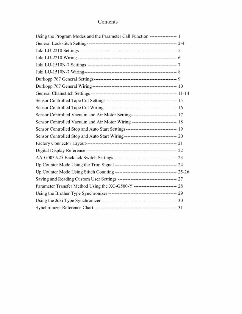
Contents
Using the Program Modes and the Parameter Call Function ----------------- 1 General Lockstitch Settings ------------------------------------------------------- 2-4 Juki LU-2210 Settings ------------------------------------------------------------- 5 Juki LU-2210 Wiring -------------------------------------------------------------- 6 Juki LU-1510N-7 Settings -------------------------------------------------------- 7 Juki LU-1510N-7 Wiring---------------------------------------------------------- 8 Durkopp 767 General Settings---------------------------------------------------- 9 Durkopp 767 General Wiring ----------------------------------------------------- 10 General Chainstitch Settings ------------------------------------------------------ 11-14 Sensor Controlled Tape Cut Settings -------------------------------------------- 15 Sensor Controlled Tape Cut Wiring---------------------------------------------- 16 Sensor Controlled Vacuum and Air Motor Settings --------------------------- 17 Sensor Controlled Vacuum and Air Motor Wiring ---------------------------- 18 Sensor Controlled Stop and Auto Start Settings-------------------------------- 19 Sensor Controlled Stop and Auto Start Wiring --------------------------------- 20 Factory Connector Layout--------------------------------------------------------- 21 Digital Display Reference --------------------------------------------------------- 22 AA-G003-925 Backtack Switch Settings --------------------------------------- 23 Up Counter Mode Using the Trim Signal --------------------------------------- 24 Up Counter Mode Using Stitch Counting --------------------------------------- 25-26 Saving and Reading Custom User Settings ------------------------------------- 27 Parameter Transfer Method Using the XC-G500-Y --------------------------- 28 Using the Brother Type Synchronizer ------------------------------------------- 29 Using the Juki Type Synchronizer ----------------------------------------------- 30 Synchronizer Reference Chart ---------------------------------------------------- 31
Using Program Modes or Parameter Call Function to Customize User Settings
Program Mode Method The Normal Mode has the rotating circle
When entering into one of the program modes, press and hold in the proper keys until the display stops flashing
To return to the Normal Mode from any Program Mode, press the ↓ + ↑ momentarily P-Mode ↓ + ↑ General Settings
A-Mode ↓ + A
B-Mode ↓ + B
C-Mode ↓ + C
D-Mode ↓ + D
E-Mode ↓ + ↑ + A Troubleshooting
F-Mode ↓ + ↑ + B
G-Mode ↓ + ↑ + C
H-Mode ↓ + ↑ + D
J-Mode ↓ + ↑ + A + B
Q-Mode ↓ + A + C
R-Mode ↓ + B + C Reset Mode
S-Mode ↓ + B + D
K-Mode ↓ + ↑ + A + C
I-Mode ↓ + ↑ + B + C Parameter Save
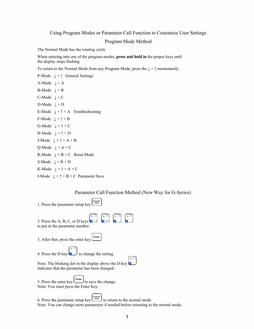
Parameter Call Function Method (New Way for G-Series)
1. Press the parameter setup key
2. Press the A, B, C, or D keys to put in the parameter number.
3. After that, press the enter key
4. Press the D-key to change the setting.
Note: The blinking dot in the display above the D-key indicates that the parameter has been changed.
5. Press the enter key to save the change. Note: You must press the Enter Key.
6. Press the parameter setup key to return to the normal mode. Note: You can change more parameters if needed before returning to the normal mode.
1
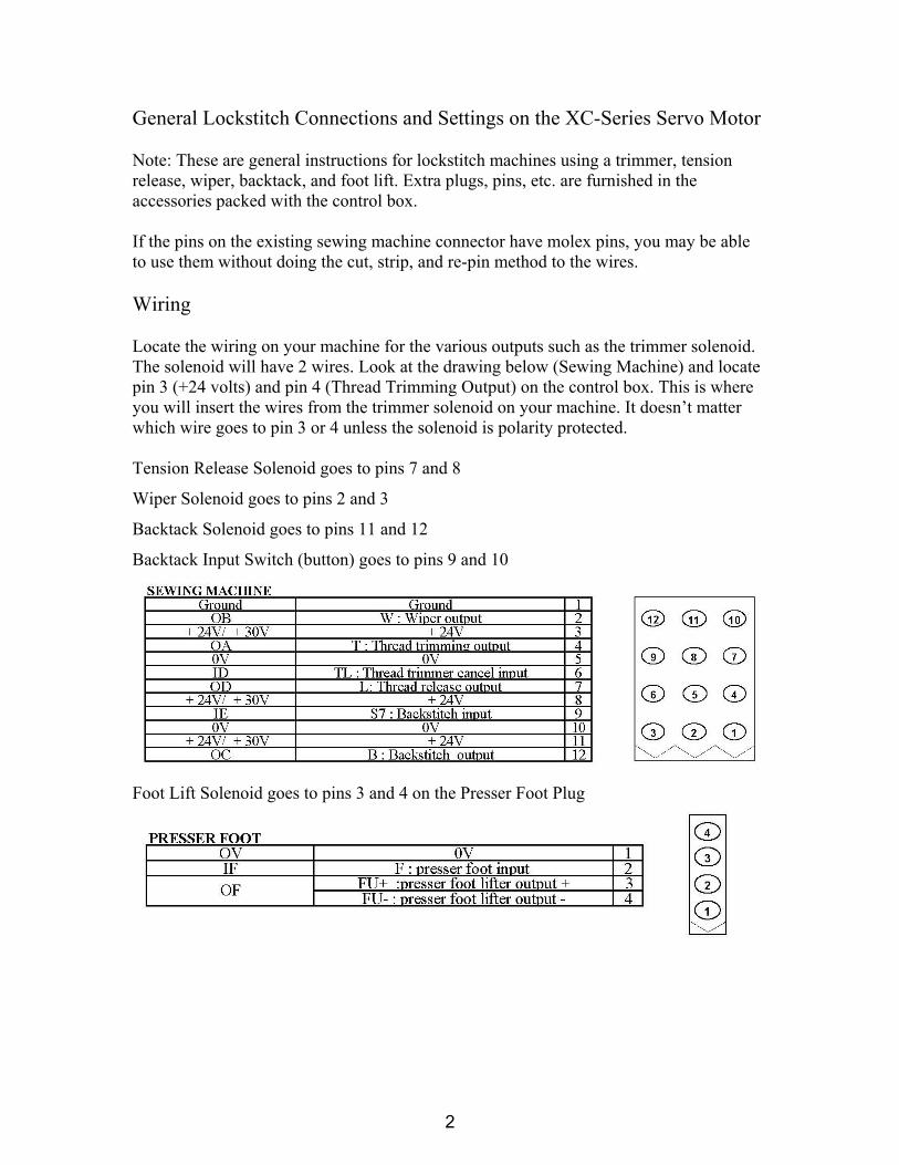
General Lockstitch Connections and Settings on the XC-Series Servo Motor Note: These are general instructions for lockstitch machines using a trimmer, tension release, wiper, backtack, and foot lift. Extra plugs, pins, etc. are furnished in the accessories packed with the control box. If the pins on the existing sewing machine connector have molex pins, you may be able to use them without doing the cut, strip, and re-pin method to the wires. Wiring Locate the wiring on your machine for the various outputs such as the trimmer solenoid. The solenoid will have 2 wires. Look at the drawing below (Sewing Machine) and locate pin 3 (+24 volts) and pin 4 (Thread Trimming Output) on the control box. This is where you will insert the wires from the trimmer solenoid on your machine. It doesn’t matter which wire goes to pin 3 or 4 unless the solenoid is polarity protected. Tension Release Solenoid goes to pins 7 and 8
Wiper Solenoid goes to pins 2 and 3
Backtack Solenoid goes to pins 11 and 12
Backtack Input Switch (button) goes to pins 9 and 10
Foot Lift Solenoid goes to pins 3 and 4 on the Presser Foot Plug
2
Control Box Settings Note: After you select a program mode like the P-Mode:
• Press the ↓ arrow key to move forward through the list of functions • Press the A, B, C, or D keys to change the setting • Press the ↓ arrow key and the ↑ arrow key momentarily to return to the normal mode
Note: You must return to the normal mode before you can go to another program mode
---The normal mode has the rotating circle---
P-Mode
Press and hold in the ↓ + ↑ arrow keys until the display stops flashing H High Speed (0-8999)
N Start Backtack Speed (0-2999)
V End Backtack Speed (0-2999)
RU Reverse after Trim (OF/ON) Optional for Walking Foot Machines
R8 Degree of Reverse after Trim (0-360) Optional for Walking Foot Machines
TR Change from M1 to PRG------This is the setting for the trimmer. Without the
sewing machine connector plugged in, adjust the synchronizer so the take-up stops
at the up position after full treadle heel back. Adjust the needle down position by
rotating the red disk on the synchronizer. The down position is the signal to activate
the trimmer, so it needs to be set to match the mechanical movement of the
trimmer mechanism. Once the trimmer is activated, the signal will stay on until the
take-up level on the machine reaches the top position. This makes the PRG setting
ideal for most all lockstitch machines. Plug in the sewing machine connector and test
the machine. The red disk may need to be re-adjusted to fine tune the electric signal
which moves the roller into the trim cam area properly.
A-MODE Press and hold in the ↓ + A keys until the display stops flashing GA Motor Torque Gain (H, L, LL) High, Low, Very Low (If you are using a Walking Foot Machine, set to H. A smaller motor pulley than the standard 100mm is also recommended for added motor torque if needed.) End
3
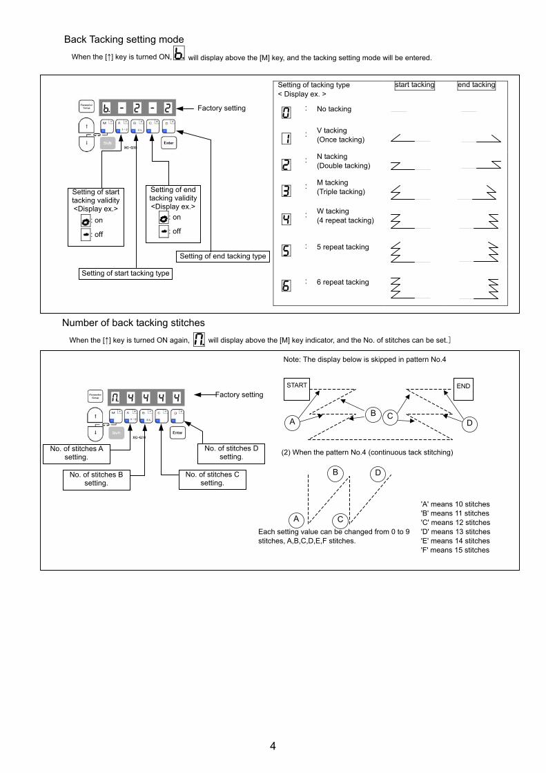
Back Tacking setting mode
When the [↑] key is turned ON, will display above the [M] key, and the tacking setting mode will be entered.
Setting of tacking type < Display ex. >
start tacking end tacking
: No tacking
:V tacking (Once tacking)
:N tacking (Double tacking)
:M tacking (Triple tacking)
:W tacking (4 repeat tacking)
: 5 repeat tacking
: 6 repeat tacking
Number of back tacking stitches When the [↑] key is turned ON again, will display above the [M] key indicator, and the No. of stitches can be set.]
Note: The display below is skipped in pattern No.4
(2) When the pattern No.4 (continuous tack stitching)
Each setting value can be changed from 0 to 9 stitches, A,B,C,D,E,F stitches.
'A' means 10 stitches 'B' means 11 stitches 'C' means 12 stitches 'D' means 13 stitches 'E' means 14 stitches 'F' means 15 stitches
Factory setting
Setting of start tacking type
Setting of start tacking validity <Display ex.>
: on
: off
Setting of end tacking validity <Display ex.>
: on
: off
Setting of end tacking type
Factory setting
No. of stitches B setting.
No. of stitches A setting.
No. of stitches C setting.
No. of stitches D setting.
START END
AB C
D
A
B
C
D
4
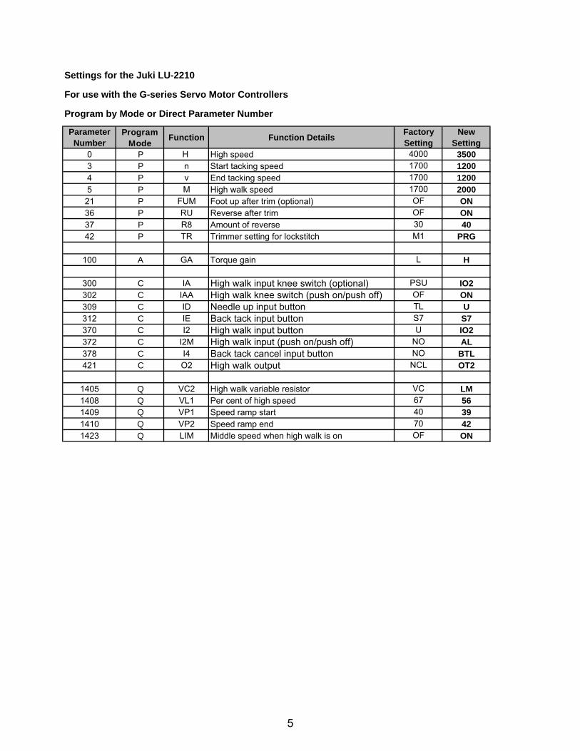
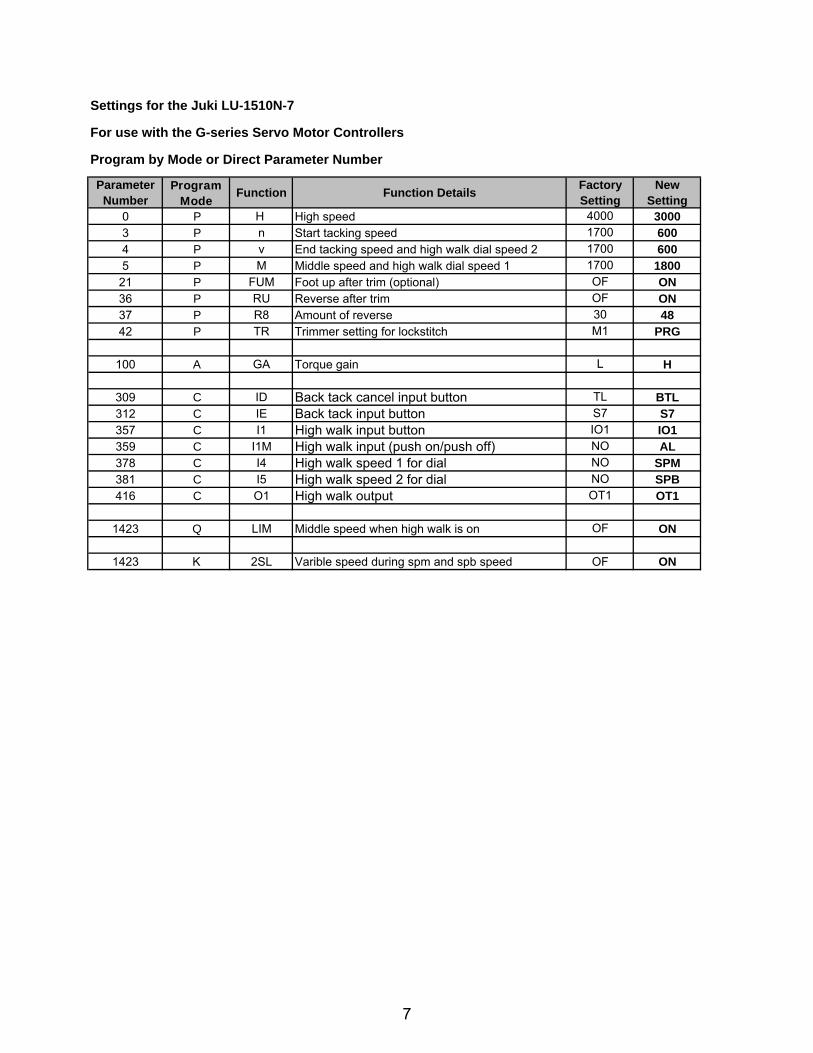
Settings for the Juki LU-2210
For use with the G-series Servo Motor Controllers
Program by Mode or Direct Parameter Number
ParameterNumber
Program Mode
Function Function Details Factory Setting
New Setting
0 P H High speed 4000 35003 P n Start tacking speed 1700 12004 P v End tacking speed 1700 12005 P M High walk speed 1700 2000
21 P FUM Foot up after trim (optional) OF ON36 P RU Reverse after trim OF ON37 P R8 Amount of reverse 30 4042 P TR Trimmer setting for lockstitch M1 PRG
100 A GA Torque gain L H
300 C IA High walk input knee switch (optional) PSU IO2302 C IAA High walk knee switch (push on/push off) OF ON309 C ID Needle up input button TL U312 C IE Back tack input button S7 S7370 C I2 High walk input button U IO2372 C I2M High walk input (push on/push off) NO AL378 C I4 Back tack cancel input button NO BTL421 C O2 High walk output NCL OT2
1405 Q VC2 High walk variable resistor VC LM1408 Q VL1 Per cent of high speed 67 561409 Q VP1 Speed ramp start 40 391410 Q VP2 Speed ramp end 70 421423 Q LIM Middle speed when high walk is on OF ON
5
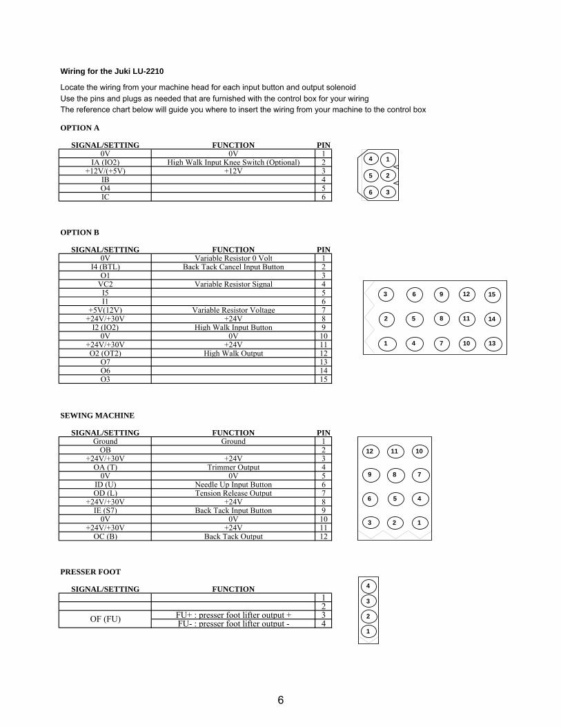
Wiring for the Juki LU-2210
Locate the wiring from your machine head for each input button and output solenoidUse the pins and plugs as needed that are furnished with the control box for your wiringThe reference chart below will guide you where to insert the wiring from your machine to the control box
OPTION A
SIGNAL/SETTING FUNCTION PIN0V 0V 1
IA (IO2) High Walk Input Knee Switch (Optional) 2+12V/(+5V) +12V 3
IB 4O4 5IC 6
OPTION B
SIGNAL/SETTING FUNCTION PIN0V Variable Resistor 0 Volt 1
I4 (BTL) Back Tack Cancel Input Button 2O1 3
VC2 Variable Resistor Signal 4I5 5I1 6
+5V(12V) Variable Resistor Voltage 7+24V/+30V +24V 8
I2 (IO2) High Walk Input Button 90V 0V 10
+24V/+30V +24V 11O2 (OT2) High Walk Output 12
O7 13O6 14O3 15
SEWING MACHINE
SIGNAL/SETTING FUNCTION PINGround Ground 1
OB 2+24V/+30V +24V 3
OA (T) Trimmer Output 40V 0V 5
ID (U) Needle Up Input Button 6OD (L) Tension Release Output 7
0 P H High speed 4000 30003 P n Start tacking speed 1700 6004 P v End tacking speed and high walk dial speed 2 1700 6005 P M Middle speed and high walk dial speed 1 1700 1800
21 P FUM Foot up after trim (optional) OF ON36 P RU Reverse after trim OF ON37 P R8 Amount of reverse 30 4842 P TR Trimmer setting for lockstitch M1 PRG
100 A GA Torque gain L H
309 C ID Back tack cancel input button TL BTL312 C IE Back tack input button S7 S7357 C I1 High walk input button IO1 IO1359 C I1M High walk input (push on/push off) NO AL378 C I4 High walk speed 1 for dial NO SPM381 C I5 High walk speed 2 for dial NO SPB416 C O1 High walk output OT1 OT1
1423 Q LIM Middle speed when high walk is on OF ON
1423 K 2SL Varible speed during spm and spb speed OF ON
7
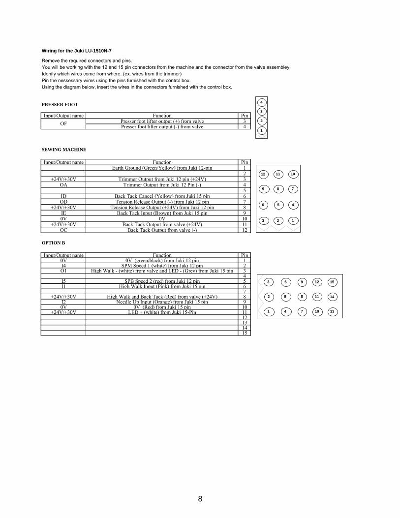
Wiring for the Juki LU-1510N-7
Remove the required connectors and pins. You will be working with the 12 and 15 pin connectors from the machine and the connector from the valve assembley.Idenify which wires come from where. (ex. wires from the trimmer)Pin the nessessary wires using the pins furnished with the control box.Using the diagram below, insert the wires in the connectors furnished with the control box.
PRESSER FOOT
Input/Output name Function PinOF Presser foot lifter output (+) from valve 3
Presser foot lifter output (-) from valve 4
SEWING MACHINE
Input/Output name Function PinEarth Ground (Green/Yellow) from Juki 12-pin 1
2+24V/+30V Trimmer Output from Juki 12 pin (+24V) 3
OA Trimmer Output from Juki 12 Pin (-) 45
ID Back Tack Cancel (Yellow) from Juki 15 pin 6OD Tension Release Output (-) from Juki 12 pin 7
+24V/+30V Tension Release Output (+24V) from Juki 12 pin 8IE Back Tack Input (Brown) from Juki 15 pin 90V 0V 10
+24V/+30V Back Tack Output from valve (+24V) 11OC Back Tack Output from valve (-) 12
OPTION B
Input/Output name Function Pin0V 0V (green/black) from Juki 12 pin 1I4 SPM Speed 1 (white) from Juki 12 pin 2O1 High Walk - (white) from valve and LED - (Grey) from Juki 15 pin 3
4I5 SPB Speed 2 (red) from Juki 12 pin 5I1 High Walk Input (Pink) from Juki 15 pin 6
7+24V/+30V High Walk and Back Tack (Red) from valve (+24V) 8
I2 Needle Up Input (Orange) from Juki 15 pin 90V 0V (Red) from Juki 15 pin 10
+24V/+30V LED + (white) from Juki 15-Pin 1112131415
11
10 13
14
15
4
2
3 6 9
5 8
7
12
12 11 10
9 8 7
6 5 4
3 2 1
4
3
2
1
1
8
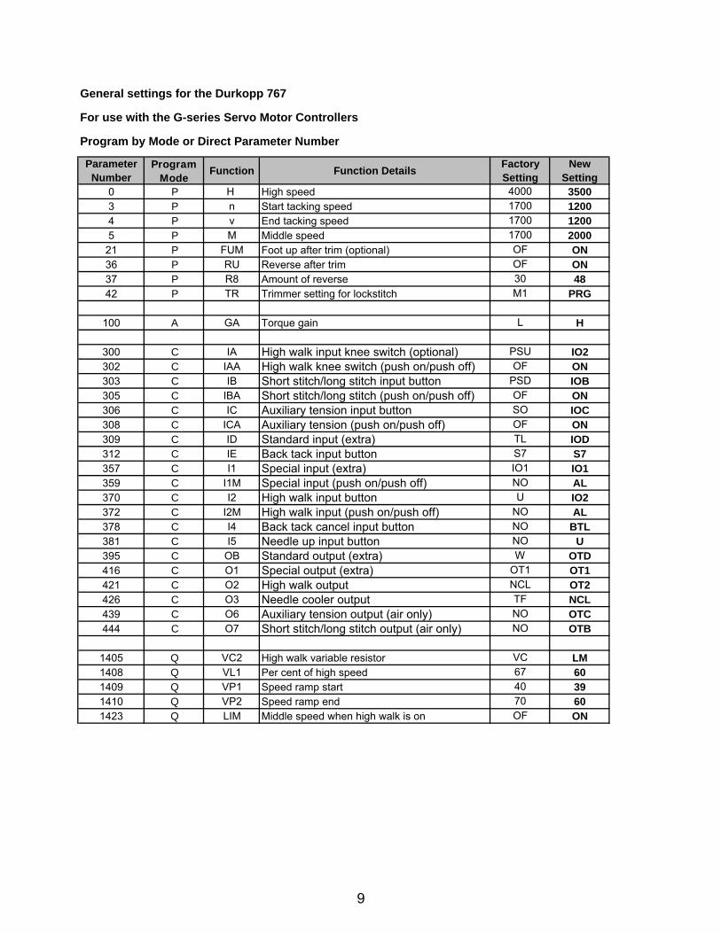
General settings for the Durkopp 767
For use with the G-series Servo Motor Controllers
Program by Mode or Direct Parameter Number
ParameterNumber
Program Mode
Function Function Details Factory Setting
New Setting
0 P H High speed 4000 35003 P n Start tacking speed 1700 12004 P v End tacking speed 1700 12005 P M Middle speed 1700 2000
21 P FUM Foot up after trim (optional) OF ON36 P RU Reverse after trim OF ON37 P R8 Amount of reverse 30 4842 P TR Trimmer setting for lockstitch M1 PRG
100 A GA Torque gain L H
300 C IA High walk input knee switch (optional) PSU IO2302 C IAA High walk knee switch (push on/push off) OF ON303 C IB Short stitch/long stitch input button PSD IOB305 C IBA Short stitch/long stitch (push on/push off) OF ON306 C IC Auxiliary tension input button SO IOC308 C ICA Auxiliary tension (push on/push off) OF ON309 C ID Standard input (extra) TL IOD312 C IE Back tack input button S7 S7357 C I1 Special input (extra) IO1 IO1359 C I1M Special input (push on/push off) NO AL370 C I2 High walk input button U IO2372 C I2M High walk input (push on/push off) NO AL378 C I4 Back tack cancel input button NO BTL381 C I5 Needle up input button NO U395 C OB Standard output (extra) W OTD416 C O1 Special output (extra) OT1 OT1421 C O2 High walk output NCL OT2426 C O3 Needle cooler output TF NCL439 C O6 Auxiliary tension output (air only) NO OTC444 C O7 Short stitch/long stitch output (air only) NO OTB
1405 Q VC2 High walk variable resistor VC LM1408 Q VL1 Per cent of high speed 67 601409 Q VP1 Speed ramp start 40 391410 Q VP2 Speed ramp end 70 601423 Q LIM Middle speed when high walk is on OF ON
9
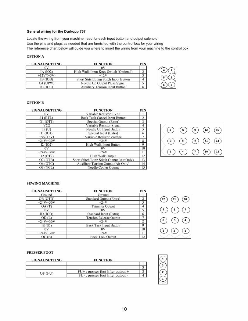
General wiring for the Durkopp 767
Locate the wiring from your machine head for each input button and output solenoidUse the pins and plugs as needed that are furnished with the control box for your wiringThe reference chart below will guide you where to insert the wiring from your machine to the control box
OPTION A
SIGNAL/SETTING FUNCTION PIN0V 0V 1
IA (IO2) High Walk Input Knee Switch (Optional) 2+12V/(+5V) +12V 3
IB (IOB) Short Stitch/Long Stitch Input Button 4O4 (UPW) Needle Up Output Pluse Signal 5IC (IOC) Auxiliary Tension Input Button 6
OPTION B
SIGNAL/SETTING FUNCTION PIN0V Variable Resistor 0 Volt 1
I4 (BTL) Back Tack Cancel Input Button 2O1 (OT1) Special Output (Extra) 3
VC2 Variable Resistor Signal 4I5 (U) Needle Up Input Button 5
I1 (IO1) Special Input (Extra) 6+5V(12V) Variable Resistor Voltage 7
+24V/+30V +24V 8I2 (IO2) High Walk Input Button 9
0V 0V 10+24V/+30V +24V 11O2 (OT2) High Walk Output 12O7 (OTB) Short Stitch/Long Stitch Output (Air Only) 13O6 (OTC) Auxiliary Tension Output (Air Only) 14O3 (NCL) Needle Cooler Output 15
SEWING MACHINE
SIGNAL/SETTING FUNCTION PINGround Ground 1
OB (OTD) Standard Output (Extra) 2+24V/+30V +24V 3
OA (T) Trimmer Output 40V 0V 5
ID (IOD) Standard Input (Extra) 6OD (L) Tension Release Output 7
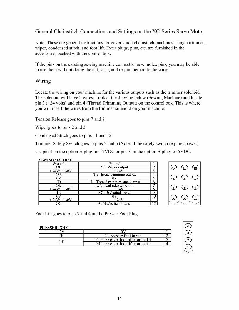
General Chainstitch Connections and Settings on the XC-Series Servo Motor Note: These are general instructions for cover stitch chainstitch machines using a trimmer, wiper, condensed stitch, and foot lift. Extra plugs, pins, etc. are furnished in the accessories packed with the control box. If the pins on the existing sewing machine connector have molex pins, you may be able to use them without doing the cut, strip, and re-pin method to the wires. Wiring Locate the wiring on your machine for the various outputs such as the trimmer solenoid. The solenoid will have 2 wires. Look at the drawing below (Sewing Machine) and locate pin 3 (+24 volts) and pin 4 (Thread Trimming Output) on the control box. This is where you will insert the wires from the trimmer solenoid on your machine. Tension Release goes to pins 7 and 8
Wiper goes to pins 2 and 3
Condensed Stitch goes to pins 11 and 12
Trimmer Safety Switch goes to pins 5 and 6 (Note: If the safety switch requires power,
use pin 3 on the option A plug for 12VDC or pin 7 on the option B plug for 5VDC.
Foot Lift goes to pins 3 and 4 on the Presser Foot Plug
11
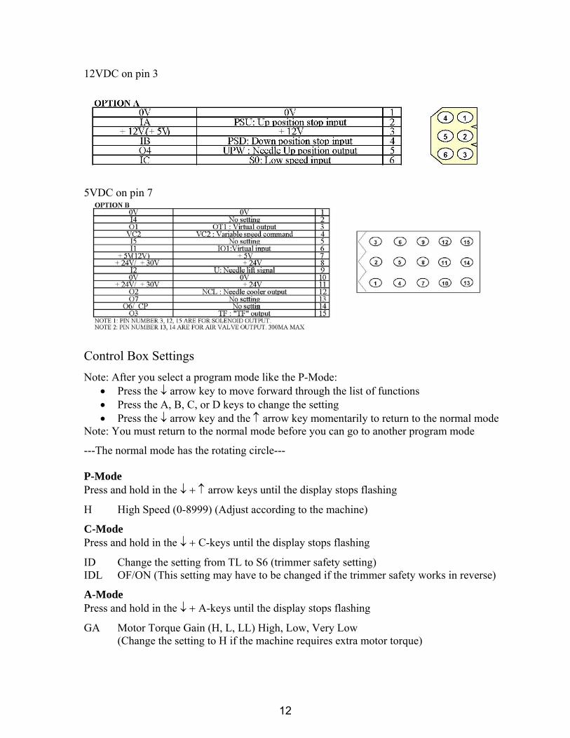
12VDC on pin 3
5VDC on pin 7
Control Box Settings Note: After you select a program mode like the P-Mode:
• Press the ↓ arrow key to move forward through the list of functions • Press the A, B, C, or D keys to change the setting • Press the ↓ arrow key and the ↑ arrow key momentarily to return to the normal mode
Note: You must return to the normal mode before you can go to another program mode
---The normal mode has the rotating circle--- P-Mode Press and hold in the ↓ + ↑ arrow keys until the display stops flashing H High Speed (0-8999) (Adjust according to the machine)
C-Mode Press and hold in the ↓ + C-keys until the display stops flashing
ID Change the setting from TL to S6 (trimmer safety setting) IDL OF/ON (This setting may have to be changed if the trimmer safety works in reverse)
A-Mode Press and hold in the ↓ + A-keys until the display stops flashing
GA Motor Torque Gain (H, L, LL) High, Low, Very Low (Change the setting to H if the machine requires extra motor torque)
12
G-Mode Press and hold in the ↓ + ↑ + C keys until the display stops flashing
TR Change from M1 to PRG (Trimmer settings become changeable)
LTM Change from T1 to TK (Trim after up position for cover stitch chainstitch machines)
Note: The next items are changes that can be made from the default settings to customize the
various cover stitch chainstitch models
T1 20ms (Changeable from 0-998ms) (Delay before the trimmer turns on)
T2 90ms (Changeable from 0-998ms) (Duration of the trimmer on time)
W1 10ms---x10 (Changeable from 0-998ms---x10) (Delay before the wiper turns on)
W2 8ms---x10 (Changeable from 0-998ms---x10) (Duration of the wiper on time)
F1 140ms (0-998ms) Presser foot delay to raise after trim
End
13
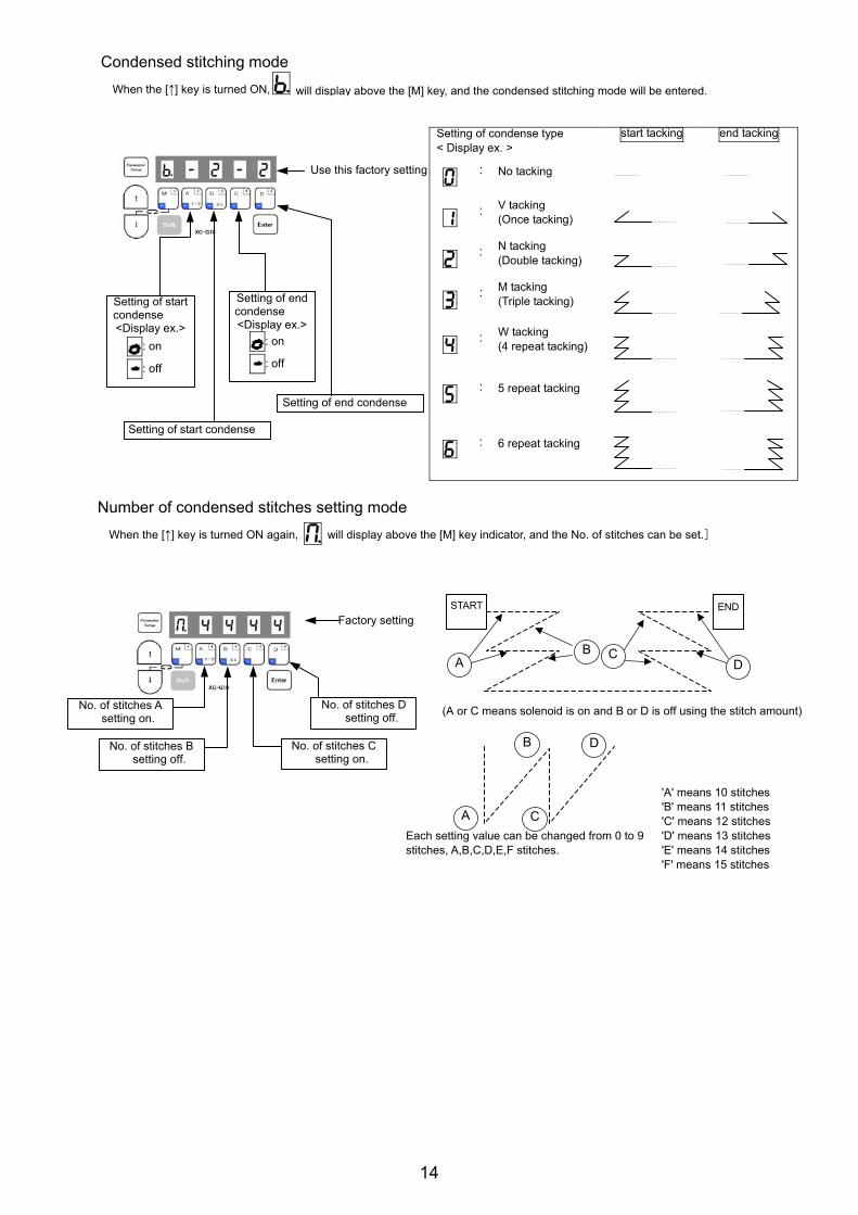
Condensed stitching mode When the [↑] key is turned ON, will display above the [M] key, and the condensed stitching mode will be entered.
Setting of condense type < Display ex. >
start tacking end tacking
: No tacking
:V tacking (Once tacking)
:N tacking (Double tacking)
:M tacking (Triple tacking)
:W tacking (4 repeat tacking)
: 5 repeat tacking
: 6 repeat tacking
Number of condensed stitches setting mode When the [↑] key is turned ON again, will display above the [M] key indicator, and the No. of stitches can be set.]
(A or C means solenoid is on and B or D is off using the stitch amount)
Each setting value can be changed from 0 to 9 stitches, A,B,C,D,E,F stitches.
'A' means 10 stitches 'B' means 11 stitches 'C' means 12 stitches 'D' means 13 stitches 'E' means 14 stitches 'F' means 15 stitches
Use this factory setting
Setting of start condense
Setting of start condense <Display ex.>
: on
: off
Setting of end condense <Display ex.>
: on
: off
Setting of end condense
Factory setting
No. of stitches B setting off.
No. of stitches A setting on.
No. of stitches C setting on.
No. of stitches D setting off.
START END
AB C
D
A
B
C
D
14
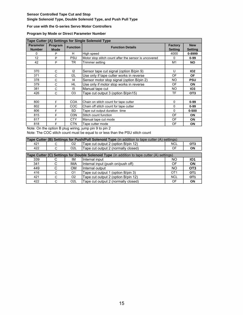
Sensor Controlled Tape Cut and Stop Single Solenoid Type, Double Solenoid Type, and Push Pull Type
For use with the G-series Servo Motor Controllers
Program by Mode or Direct Parameter Number
Tape Cutter (A) Settings for Single Solenoid TypeParameter
NumberProgram
ModeFunction Function Details Factory
SettingNew
Setting0 P H High speed 4000 0-8999
12 P PSU Motor stop stitch count after the sensor is uncovered 0 0-9942 P TR Trimmer setting M1 NO
370 C I2 Sensor tape cut signal (option B/pin 9) U IO2371 C I2L Use only if tape cutter works in reverse OF OF378 C I4 Sensor motor stop signal (option B/pin 2) NO PSU379 C I4L Use only if motor stop works in reverse OF ON381 C I5 Manual tape cut NO IO3426 C O3 Tape cut output 3 (option B/pin15) TF OT3
800 F COA Chain on stitch count for tape cutter 0 0-99802 F COC Chain off stitch count for tape cutter 0 0-99806 F SD Tape cut output duration time 0 0-500815 F O3N Stitch count function OF ON817 F CTY Manual tape cut mode OF ON818 F CTN Tape cutter mode OF ON
Note: On the option B plug wiring, jump pin 9 to pin 2Note: The COC stitch count must be equal to or less than the PSU stitch count
Tape Cutter (B) Settings for Push/Pull Solenoid Type (in addition to tape cutter (A) settings)421 C O2 Tape cut output 2 (option B/pin 12) NCL OT3422 C O2L Tape cut output 2 (normally closed) OF ON
Tape Cutter (C) Settings for Double Solenoid Type (in addition to tape cutter (A) settings)339 C IM Internal input NO IO1341 C IMA Internal input (push on/push off) OF ON449 C OM Internal output NO OT3416 C O1 Tape cut output 1 (option B/pin 3) OT1 OT1421 C O2 Tape cut output 2 (option B/pin 12) NCL OT1422 C O2L Tape cut output 2 (normally closed) OF ON
15
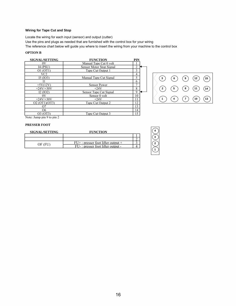
Wiring for Tape Cut and Stop
Locate the wiring for each input (sensor) and output (cutter)Use the pins and plugs as needed that are furnished with the control box for your wiringThe reference chart below will guide you where to insert the wiring from your machine to the control box
OPTION B
SIGNAL/SETTING FUNCTION PIN0V Manual Tape Cut 0 volt 1
I4 (PSU) Sensor Motor Stop Signal 2O1 (OT1) Tape Cut Output 1 3
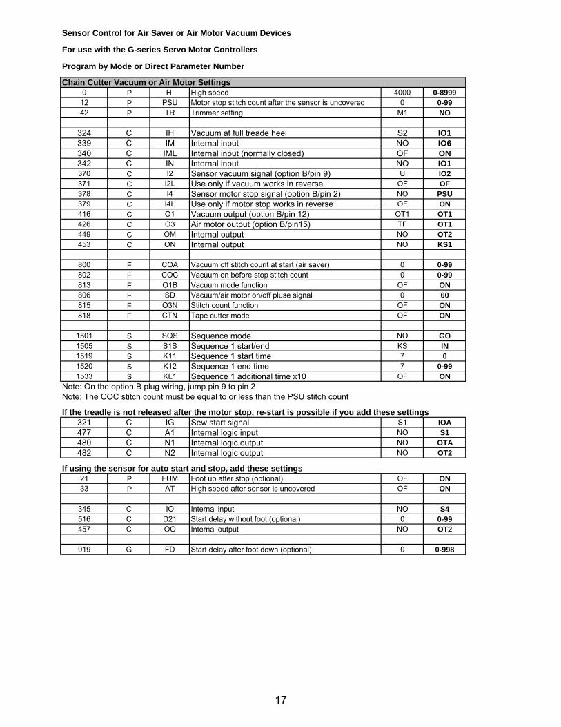
Sensor Control for Air Saver or Air Motor Vacuum Devices
For use with the G-series Servo Motor Controllers
Program by Mode or Direct Parameter Number
Chain Cutter Vacuum or Air Motor Settings 0 P H High speed 4000 0-8999
12 P PSU Motor stop stitch count after the sensor is uncovered 0 0-9942 P TR Trimmer setting M1 NO
324 C IH Vacuum at full treade heel S2 IO1339 C IM Internal input NO IO6340 C IML Internal input (normally closed) OF ON342 C IN Internal input NO IO1370 C I2 Sensor vacuum signal (option B/pin 9) U IO2371 C I2L Use only if vacuum works in reverse OF OF378 C I4 Sensor motor stop signal (option B/pin 2) NO PSU379 C I4L Use only if motor stop works in reverse OF ON416 C O1 Vacuum output (option B/pin 12) OT1 OT1426 C O3 Air motor output (option B/pin15) TF OT1449 C OM Internal output NO OT2453 C ON Internal output NO KS1
800 F COA Vacuum off stitch count at start (air saver) 0 0-99802 F COC Vacuum on before stop stitch count 0 0-99813 F O1B Vacuum mode function OF ON806 F SD Vacuum/air motor on/off pluse signal 0 60815 F O3N Stitch count function OF ON818 F CTN Tape cutter mode OF ON
1501 S SQS Sequence mode NO GO1505 S S1S Sequence 1 start/end KS IN1519 S K11 Sequence 1 start time 7 01520 S K12 Sequence 1 end time 7 0-991533 S KL1 Sequence 1 additional time x10 OF ON
Note: On the option B plug wiring, jump pin 9 to pin 2Note: The COC stitch count must be equal to or less than the PSU stitch count
If the treadle is not released after the motor stop, re-start is possible if you add these settings321 C IG Sew start signal S1 IOA477 C A1 Internal logic input NO S1480 C N1 Internal logic output NO OTA482 C N2 Internal logic output NO OT2
If using the sensor for auto start and stop, add these settings 21 P FUM Foot up after stop (optional) OF ON33 P AT High speed after sensor is uncovered OF ON
345 C IO Internal input NO S4516 C D21 Start delay without foot (optional) 0 0-99457 C OO Internal output NO OT2
919 G FD Start delay after foot down (optional) 0 0-998
17
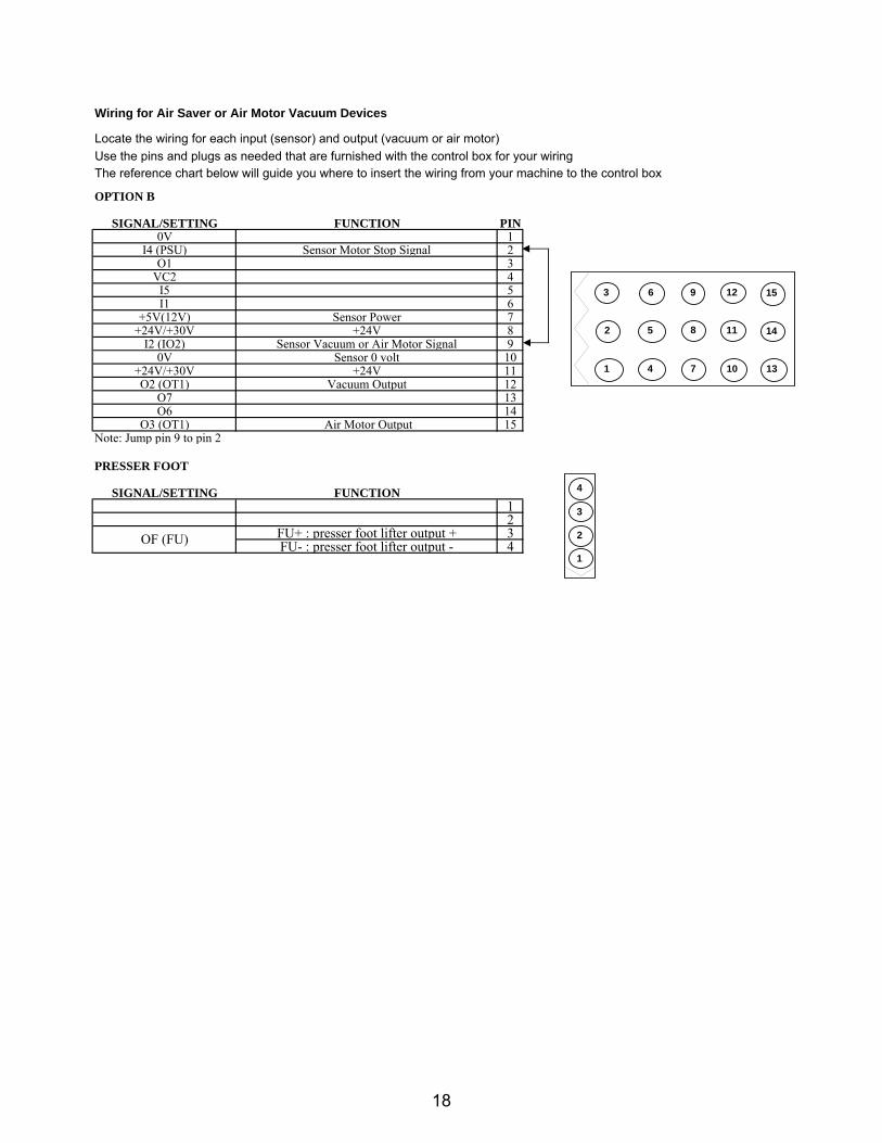
Wiring for Air Saver or Air Motor Vacuum Devices
Locate the wiring for each input (sensor) and output (vacuum or air motor)Use the pins and plugs as needed that are furnished with the control box for your wiringThe reference chart below will guide you where to insert the wiring from your machine to the control box
OPTION B
SIGNAL/SETTING FUNCTION PIN0V 1
I4 (PSU) Sensor Motor Stop Signal 2O1 3
VC2 4I5 5I1 6
+5V(12V) Sensor Power 7+24V/+30V +24V 8
I2 (IO2) Sensor Vacuum or Air Motor Signal 90V Sensor 0 volt 10
+24V/+30V +24V 11O2 (OT1) Vacuum Output 12
O7 13O6 14
O3 (OT1) Air Motor Output 15Note: Jump pin 9 to pin 2
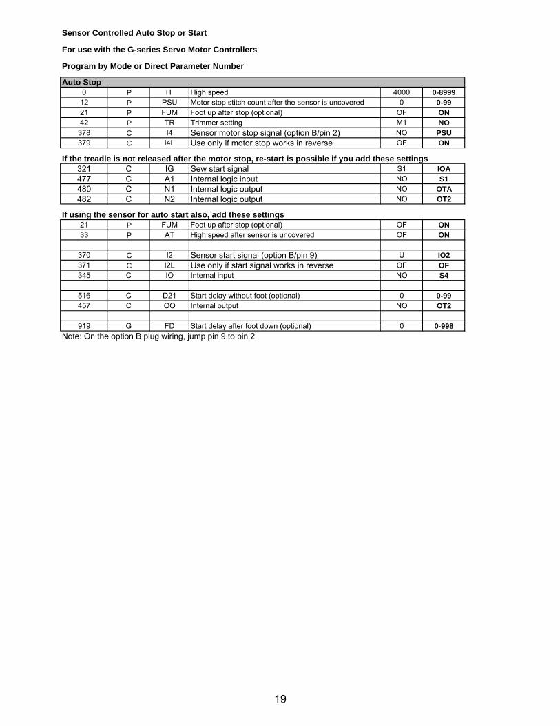
12 P PSU Motor stop stitch count after the sensor is uncovered 0 0-9921 P FUM Foot up after stop (optional) OF ON42 P TR Trimmer setting M1 NO
378 C I4 Sensor motor stop signal (option B/pin 2) NO PSU379 C I4L Use only if motor stop works in reverse OF ON
If the treadle is not released after the motor stop, re-start is possible if you add these settings321 C IG Sew start signal S1 IOA477 C A1 Internal logic input NO S1480 C N1 Internal logic output NO OTA482 C N2 Internal logic output NO OT2
If using the sensor for auto start also, add these settings 21 P FUM Foot up after stop (optional) OF ON33 P AT High speed after sensor is uncovered OF ON
370 C I2 Sensor start signal (option B/pin 9) U IO2371 C I2L Use only if start signal works in reverse OF OF345 C IO Internal input NO S4
516 C D21 Start delay without foot (optional) 0 0-99457 C OO Internal output NO OT2
919 G FD Start delay after foot down (optional) 0 0-998Note: On the option B plug wiring, jump pin 9 to pin 2
19
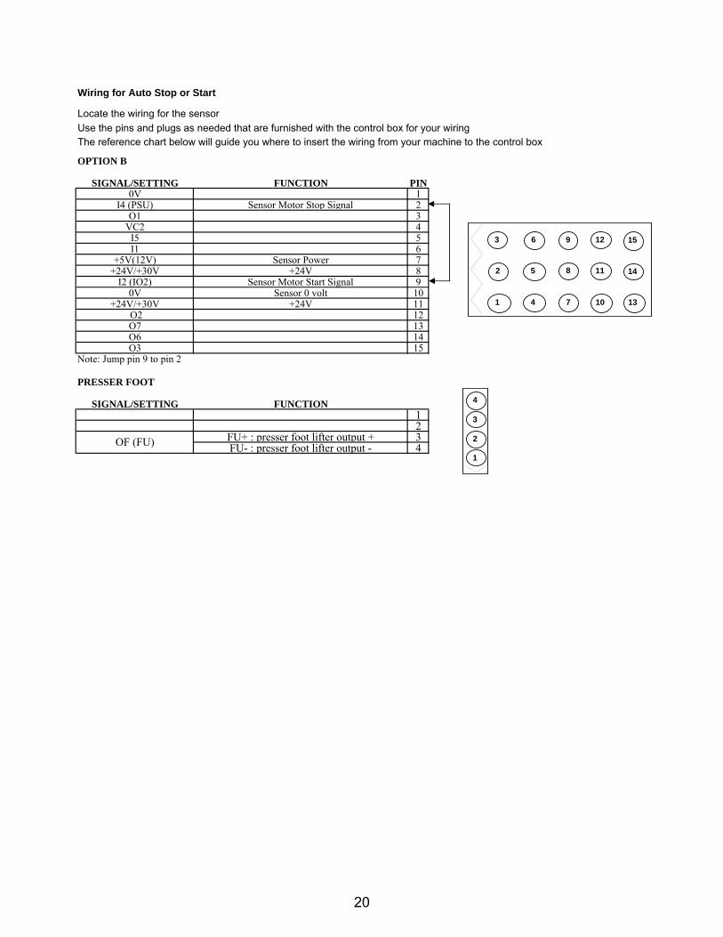
Wiring for Auto Stop or Start
Locate the wiring for the sensorUse the pins and plugs as needed that are furnished with the control box for your wiringThe reference chart below will guide you where to insert the wiring from your machine to the control box
OPTION B
SIGNAL/SETTING FUNCTION PIN0V 1
I4 (PSU) Sensor Motor Stop Signal 2O1 3
VC2 4I5 5I1 6
+5V(12V) Sensor Power 7+24V/+30V +24V 8
I2 (IO2) Sensor Motor Start Signal 90V Sensor 0 volt 10
NOTE 1: PIN NUMBER 3, 12, 15 ARE FOR SOLENOID OUTPUT.NOTE 2: PIN NUMBER 13, 14 ARE FOR AIR VALVE OUTPUT. 300MA MAX
11
10 13
14
15
4
2
3 6 9
5 8
7
12
1
2
3
4
5
6
12 11 10
9 8 7
6 5 4
3 2 1
4
3
2
1
1
2
3
4
5
6
1
21
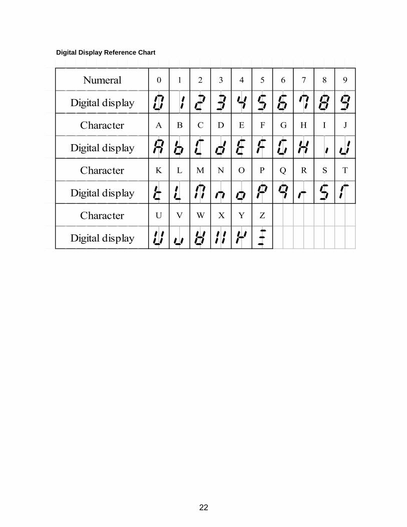
Digital Display Reference Chart
Numeral 0 1 2 3 4 5 6 7 8 9
Digital display
Character A B C D E F G H I J
Digital display
Character K L M N O P Q R S T
Digital display
Character U V W X Y Z
Digital display
22
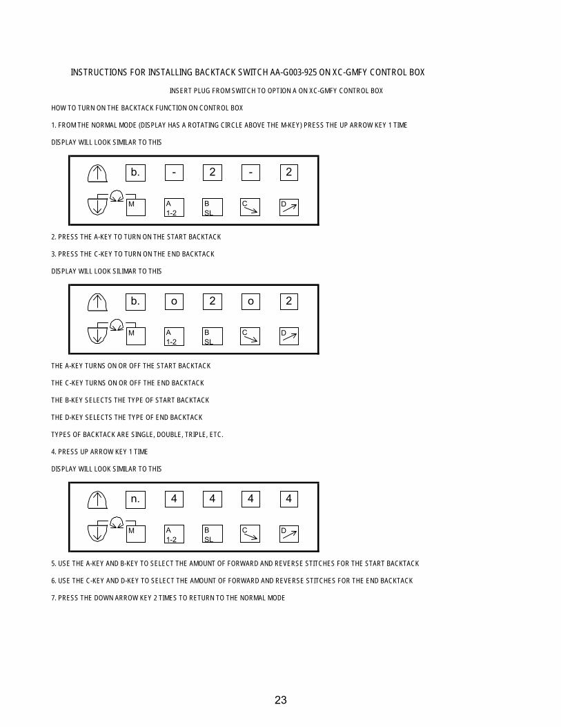
INSTRUCTIONS FOR INSTALLING BACKTACK SWITCH AA-G003-925 ON XC-GMFY CONTROL BOX
INSERT PLUG FROM SWITCH TO OPTION A ON XC-GMFY CONTROL BOX
HOW TO TURN ON THE BACKTACK FUNCTION ON CONTROL BOX
1. FROM THE NORMAL MODE (DISPLAY HAS A ROTATING CIRCLE ABOVE THE M-KEY) PRESS THE UP ARROW KEY 1 TIME
DISPLAY WILL LOOK SIMILAR TO THIS
2. PRESS THE A-KEY TO TURN ON THE START BACKTACK
3. PRESS THE C-KEY TO TURN ON THE END BACKTACK
DISPLAY WILL LOOK SILIMAR TO THIS
THE A-KEY TURNS ON OR OFF THE START BACKTACK
THE C-KEY TURNS ON OR OFF THE END BACKTACK
THE B-KEY SELECTS THE TYPE OF START BACKTACK
THE D-KEY SELECTS THE TYPE OF END BACKTACK
TYPES OF BACKTACK ARE SINGLE, DOUBLE, TRIPLE, ETC.
4. PRESS UP ARROW KEY 1 TIME
DISPLAY WILL LOOK SIMILAR TO THIS
5. USE THE A-KEY AND B-KEY TO SELECT THE AMOUNT OF FORWARD AND REVERSE STITCHES FOR THE START BACKTACK
6. USE THE C-KEY AND D-KEY TO SELECT THE AMOUNT OF FORWARD AND REVERSE STITCHES FOR THE END BACKTACK
7. PRESS THE DOWN ARROW KEY 2 TIMES TO RETURN TO THE NORMAL MODE
- 2 - 2
A1-2
b.
M BSL
C D
o 2 o 2
A1-2
b.
M BSL
C D
4 4 4 4
A1-2
n.
M BSL
C D
23
USING THE XC-G500-Y FOR UP COUNTING USING THE TRIM SIGNAL COUNTER FUNCTION: ONE COUNT PER TRIM SIGNAL (LOCATED IN THE B-MODE)
1. ENTER THE B-MODE BY PRESSING AND HOLDING IN THE DOWN ARROW AND THE B-KEY
FOR 2 OR MORE SECONDS
2. USING THE DOWN ARROW KEY FIND THE SETTING P
3. USING THE C AND D-KEYS CHANGE THE 99 TO 0
4. USING THE DOWN ARROW KEY FIND THE SETTING U
5. USING THE C AND D-KEYS CHANGE THE 99 TO 0 IF NEEDED
6. USING THE DOWN ARROW KEY FIND THE SETTING UPC
7. USING THE D-KEY CHANGE THE OF TO ON
8. PRESS THE DOWN ARROW AND THE UP ARROW KEYS TOGETHER TO EXIT THE B-MODE
TO MAKE THE XC-G500-Y DISPLAY THE STITCH COUNT
1. ENTER THE C-MODE BY PRESSING AND HOLDING IN THE DOWN ARROW AND THE C-KEY FOR 2 OR
MORE SECONDS
2. USING THE UP ARROW KEY FIND THE SETTING CNF
3. USING THE D-KEY CHANGE THE FUNCTION SE TO UP
4. PRESS THE DOWN ARROW AND THE UP ARROW KEYS TOGETHER TO EXIT THE C-MODE
5. PRESS AND HOLD THE F-KEY THEN THE STEP-KEY
6. PRESS THE F-KEY TO DISPLAY STITCH COUNT
SINCE THE COUNTING IS TRIGGERED 1 TIME PER TRIM SIGNAL, RUN THE MACHINE AS NORMAL
AND WHEN THE BOBBIN RUNS OUT MAKE NOTE OF THE COUNT AMOUNT.
7. PRESS AND HOLD THE STEP-KEY THEN THE F-KEY
8. ENTER THE B-MODE BY PRESSING AND HOLDING IN THE DOWN ARROW AND THE B-KEY FOR 2 OR
MORE SECONDS
9. USING THE DOWN ARROW KEY FIND THE SETTING P
10. USING THE A, B, C, AND D-KEYS, ENTER THE TARGET COUNT FOR THE UP COUNTER
11. PRESS THE DOWN ARROW AND UP ARROW KEYS TOGETHER TO EXIT THE B-MODE
12. PRESS AND HOLD IN THE F-KEY THEN THE STEP KEY
13. PRESS THE F-KEY
14. PRESS THE P-KEY
15. PRESS THE P-KEY TO RESET AND CLEAR THE STITCH COUNT AFTER THE TARGET VALUE HAS
BEEN REACHED
NOTE: THE BUZZER WILL COME ON AFTER THE TARGET STITCH COUNT HAS BEEN REACHED AND WILL BEEP 5 TIMES. THE MACHINE WILL STILL BE ABLE TO RUN UNTIL THE TREADLE IS FULLY HEELED BACK FOR THE TRIMMER CYCLE. AT THAT TIME THE MACHINE WILL NOT RUN UNTIL THE P-KEY HAS BEEN PRESSED TO CLEAR THE COUNTER.
24
USING THE XC-G500-Y FOR UP COUNTING USING A CERTAIN AMOUNT OF REVOLUTIONS TO TRIGGER THE UP COUNTER 1 TIME
COUNTER FUNCTION: STITCH COUNT TYPE (LOCATED IN THE B-MODE)
1. ENTER THE B-MODE BY PRESSING AND HOLDING IN THE DOWN ARROW AND THE B-KEY
FOR 2 OR MORE SECONDS
2. USING THE DOWN ARROW KEY FIND THE SETTING P
3. USING THE C AND D-KEYS CHANGE THE 99 TO 0
4. USING THE DOWN ARROW KEY FIND THE SETTING U
5. USING THE C AND D-KEYS CHANGE THE 99 TO 0 IF NEEDED
6. USING THE DOWN ARROW KEY FIND THE SETTING CUP
7. USING THE D-KEY CHANGE THE FUNCTION FROM CU TO ST
8. USING THE DOWN ARROW KEY FIND THE SETTING UPC
9. USING THE D-KEY CHANGE THE OF TO ON
10. USING THE DOWN ARROW KEY FIND THE SETTING CNU
11. USING THE C, AND D-KEYS CHANGE THE 1 TO, FOR EXAMPLE 10
THIS SETTING WILL MAKE THE COUNTER COUNT 1 TIME PER 10 REVOLUTIONS
12. PRESS THE UP ARROW AND THE DOWN ARROW KEYS TOGETHER TO EXIT THE B-MODE
TO MAKE THE XC-G500-Y DISPLAY THE STITCH COUNT
1. ENTER THE C-MODE BY PRESSING AND HOLDING IN THE DOWN ARROW AND THE C-KEY FOR 2 OR
MORE SECONDS
2. USING THE UP ARROW KEY FIND THE SETTING CNF
3. USING THE D-KEY CHANGE THE FUNCTION SE TO UP
4. PRESS THE DOWN ARROW AND THE UP ARROW KEYS TOGETHER TO EXIT THE C-MODE
5. PRESS AND HOLD THE F-KEY THEN THE STEP-KEY
6. PRESS THE F-KEY TO DISPLAY STITCH COUNT
SINCE THE COUNTING IS TRIGGERED 1 TIME PER 10 REVOLUTIONS, RUN THE MACHINE AS
NORMAL AND WHEN THE BOBBIN RUNS OUT MAKE NOTE OF THE COUNT AMOUNT.
7. PRESS AND HOLD THE STEP-KEY THEN THE F-KEY
8. ENTER THE B-MODE BY PRESSING AND HOLDING IN THE DOWN ARROW AND THE B-KEY FOR 2 OR
MORE SECONDS
9. USING THE DOWN ARROW KEY FIND THE SETTING P
10. USING THE A, B, C, AND D-KEYS, ENTER THE TARGET COUNT FOR THE UP COUNTER
11. PRESS THE DOWN ARROW AND UP ARROW KEYS TOGETHER TO EXIT THE B-MODE
12. PRESS AND HOLD IN THE F-KEY THEN THE STEP KEY
13. PRESS THE F-KEY
14. PRESS THE P-KEY
25
15. PRESS THE P-KEY TO RESET AND CLEAR THE STITCH COUNT AFTER THE TARGET VALUE HAS
BEEN REACHED
NOTE: THE BUZZER WILL COME ON AFTER THE TARGET STITCH COUNT HAS BEEN REACHED AND WILL BEEP 5 TIMES. THE MACHINE WILL STILL BE ABLE TO RUN UNTIL THE TREADLE IS FULLY HEELED BACK FOR THE TRIMMER CYCLE. AT THAT TIME THE MACHINE WILL NOT RUN UNTIL THE P-KEY HAS BEEN PRESSED TO CLEAR THE COUNTER.
26
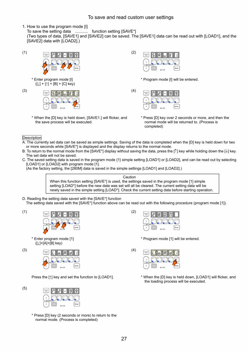
1. How to use the program mode [I]
To save the setting data ........... function setting [SAVE*] (Two types of data, [SAVE1] and [SAVE2] can be saved. The [SAVE1] data can be read out with [LOAD1], and the [SAVE2] data with [LOAD2].)
(1)
* Enter program mode [I] ([↓] + [↑] + [B] + [C] key)
(2)
* Program mode [I] will be entered.
(3)
* When the [D] key is held down, [SAVE1.] will flicker, and the save process will be executed.
(4)
* Press [D] key over 2 seconds or more, and then the normal mode will be returned to. (Process is completed)
Description
A. The currently set data can be saved as simple settings. Saving of the data is completed when the [D] key is held down for two or more seconds while [SAVE*] is displayed and the display returns to the normal mode.
B. To return to the normal mode from the [SAVE*] display without saving the data, press the [↑] key while holding down the [↓] key. The set data will not be saved.
C. The saved setting data is saved in the program mode {1} simple setting [LOAD1] or [LOAD2], and can be read out by selecting [LOAD1] or [LOAD2] with program mode [1]. (As the factory setting, the [280M] data is saved in the simple settings [LOAD1] and [LOAD2].)
Caution
When this function setting [SAVE*] is used, the settings saved in the program mode [1] simple setting [LOAD*] before the new data was set will all be cleared. The current setting data will be newly saved in the simple setting [LOAD*]. Check the current setting data before starting operation.
D. Reading the setting data saved with the [SAVE*] function
The setting data saved with the [SAVE*] function above can be read out with the following procedure (program mode [1]).
(1)
* Enter program mode [1] ([↓]+[A]+[B] key)
(2)
* Program mode [1] will be entered.
(3)
Press the [↑] key and set the function to [LOAD1].
(4)
* When the [D] key is held down, [LOAD1] will flicker, and the loading process will be executed.
(5)
* Press [D] key (2 seconds or more) to return to the normal mode. (Process is completed)
To save and read custom user settings
27
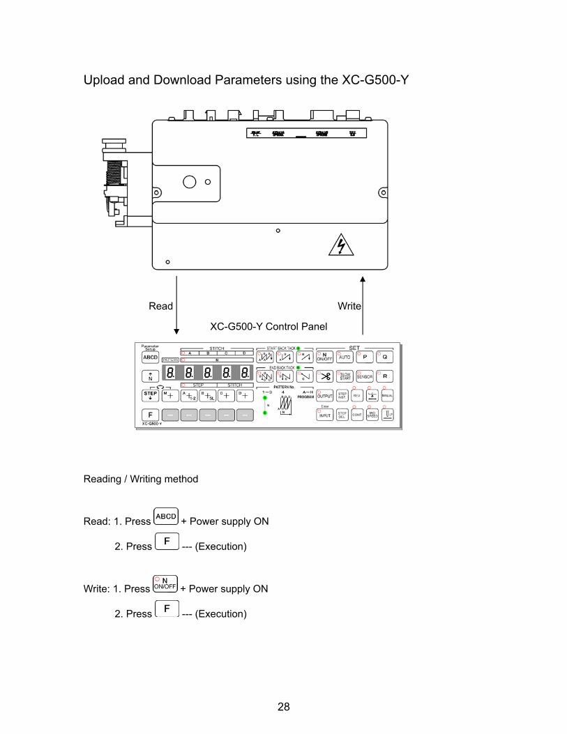
Upload and Download Parameters using the XC-G500-Y
Read Write
XC-G500-Y Control Panel
Reading / Writing method
Read: 1. Press + Power supply ON
2. Press --- (Execution)
Write: 1. Press + Power supply ON
2. Press --- (Execution)
28
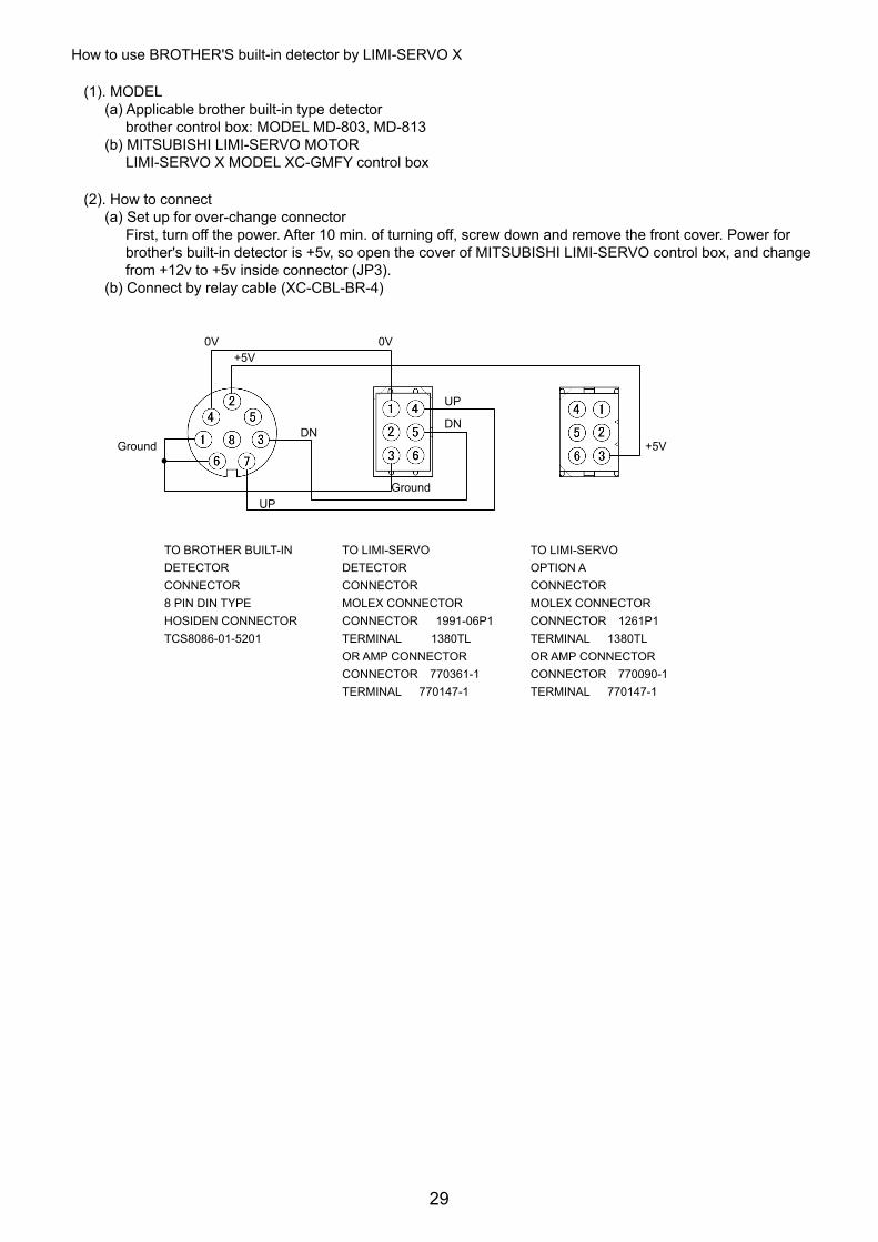
How to use BROTHER'S built-in detector by LIMI-SERVO X
(1). MODEL (a) Applicable brother built-in type detector
brother control box: MODEL MD-803, MD-813 (b) MITSUBISHI LIMI-SERVO MOTOR
LIMI-SERVO X MODEL XC-GMFY control box
(2). How to connect (a) Set up for over-change connector
First, turn off the power. After 10 min. of turning off, screw down and remove the front cover. Power for brother's built-in detector is +5v, so open the cover of MITSUBISHI LIMI-SERVO control box, and change from +12v to +5v inside connector (JP3).
(b) Connect by relay cable (XC-CBL-BR-4)
TO BROTHER BUILT-IN DETECTOR CONNECTOR 8 PIN DIN TYPE HOSIDEN CONNECTOR TCS8086-01-5201
TO LIMI-SERVO DETECTOR CONNECTOR MOLEX CONNECTOR CONNECTOR 1991-06P1 TERMINAL 1380TL OR AMP CONNECTOR CONNECTOR 770361-1 TERMINAL 770147-1
TO LIMI-SERVO OPTION A CONNECTOR MOLEX CONNECTOR CONNECTOR 1261P1 TERMINAL 1380TL OR AMP CONNECTOR CONNECTOR 770090-1 TERMINAL 770147-1
0V 0V +5V
DN Ground
UP
UP
DN
+5V
Ground
29
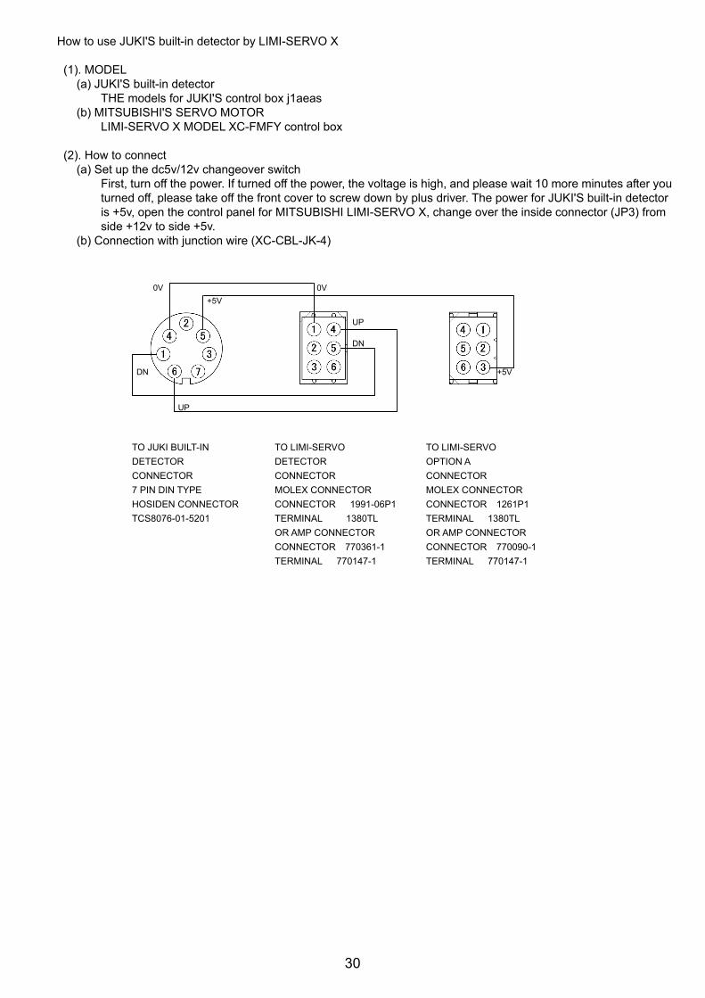
How to use JUKI'S built-in detector by LIMI-SERVO X
(1). MODEL
(a) JUKI'S built-in detector THE models for JUKI'S control box j1aeas
(b) MITSUBISHI'S SERVO MOTOR LIMI-SERVO X MODEL XC-FMFY control box
(2). How to connect
(a) Set up the dc5v/12v changeover switch First, turn off the power. If turned off the power, the voltage is high, and please wait 10 more minutes after you turned off, please take off the front cover to screw down by plus driver. The power for JUKI'S built-in detector is +5v, open the control panel for MITSUBISHI LIMI-SERVO X, change over the inside connector (JP3) from side +12v to side +5v.
(b) Connection with junction wire (XC-CBL-JK-4)
TO JUKI BUILT-IN DETECTOR CONNECTOR 7 PIN DIN TYPE HOSIDEN CONNECTOR TCS8076-01-5201
TO LIMI-SERVO DETECTOR CONNECTOR MOLEX CONNECTOR CONNECTOR 1991-06P1 TERMINAL 1380TL OR AMP CONNECTOR CONNECTOR 770361-1 TERMINAL 770147-1
TO LIMI-SERVO OPTION A CONNECTOR MOLEX CONNECTOR CONNECTOR 1261P1 TERMINAL 1380TL OR AMP CONNECTOR CONNECTOR 770090-1 TERMINAL 770147-1