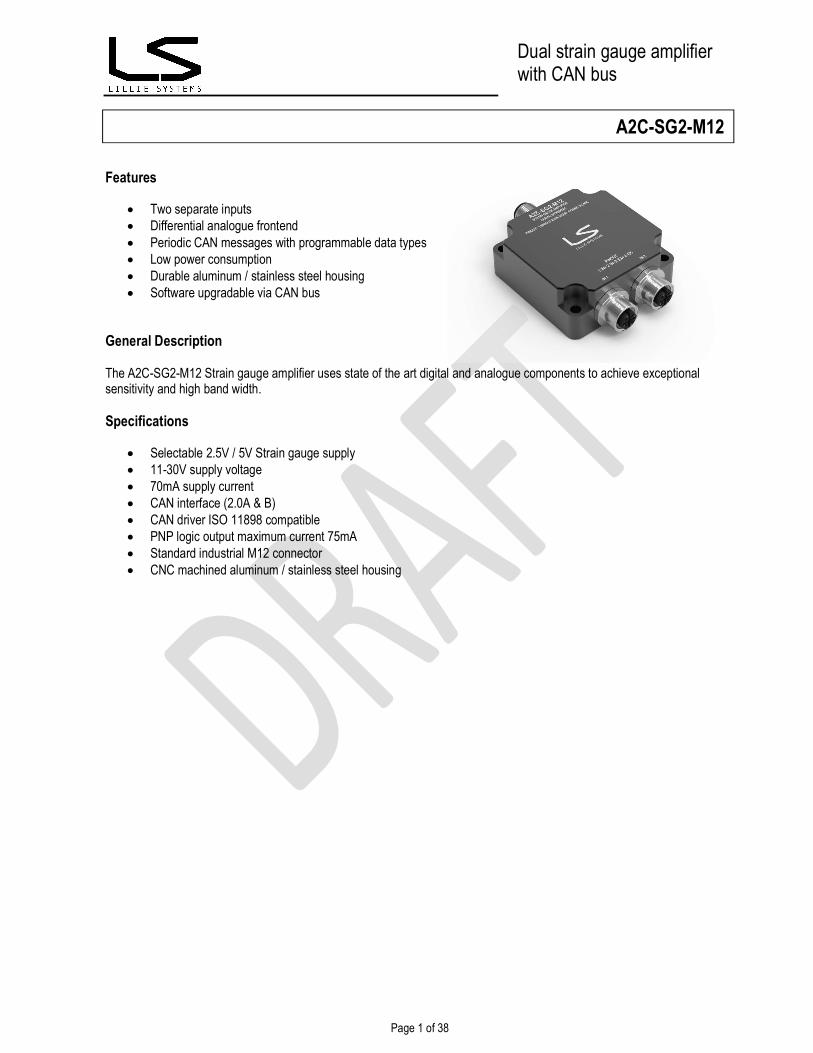
Page 1 of 38 Dual strain gauge amplifier with CAN bus Features Two separate inputs Differential analogue frontend Periodic CAN messages with programmable data types Low power consumption Durable aluminum / stainless steel housing Software upgradable via CAN bus General Description The A2C-SG2-M12 Strain gauge amplifier uses state of the art digital and analogue components to achieve exceptional sensitivity and high band width. Specifications Selectable 2.5V / 5V Strain gauge supply 11-30V supply voltage 70mA supply current CAN interface (2.0A & B) CAN driver ISO 11898 compatible PNP logic output maximum current 75mA Standard industrial M12 connector CNC machined aluminum / stainless steel housing A2C-SG2-M12
Transcript
Page 1 of 38
Dual strain gauge amplifier with CAN bus
Features
Two separate inputs Differential analogue frontend Periodic CAN messages with programmable data types Low power consumption Durable aluminum / stainless steel housing Software upgradable via CAN bus
General Description The A2C-SG2-M12 Strain gauge amplifier uses state of the art digital and analogue components to achieve exceptional sensitivity and high band width. Specifications
Selectable 2.5V / 5V Strain gauge supply 11-30V supply voltage 70mA supply current CAN interface (2.0A & B) CAN driver ISO 11898 compatible PNP logic output maximum current 75mA Standard industrial M12 connector CNC machined aluminum / stainless steel housing
A2C-SG2-M12
Page 2 of 38
Dual strain gauge amplifier with CAN bus
1 Ordering information
Part Number Package Interface CAN Bus Logic Output A2C-SG-M12-A Black anodized
aluminum M12, 5pin Male connector. Yes Yes (pin 1)
A2C-SG-M12-S Stainless steel 316 M12, 5pin Male connector. Yes Yes (pin 1) For a customer specific package please contact us. We have other materials / coatings available not listed here.
Page 3 of 38
Dual strain gauge amplifier with CAN bus
Specifications for
A2C-SG2-M12 Dual strain gauge amplifier to CAN bus
Version 1.06 17/03 2019
A2C-SG2-M12
WWW.LILLIESYSTEMS.COM 4 of 38
Document tracking control
VERSION SECTION CHANGED BY DATE CHANGE 1.00 1.01 1.02 1.03 1.04 1.05 1.06
Initial Version Updated error codes, baud rate, added SNR Added periodic messages follow ADC. Released for public viewing Added Integer Scalling section, Corrected CAN follow ADC wrong values for ints and floats New commands for periodic messages from firmware 0x0107 and onwards. New examples. Corrected wrong value to reset factory settings. Added more examples of float to byte array for calibration Added data to specifications
A2C-SG2-M12
WWW.LILLIESYSTEMS.COM 5 of 38
Contents
1 Ordering information .......................................................................................................................................................................2 Document tracking control .......................................................................................................................................................................4 2 Specifications ..................................................................................................................................................................................7
2.1 ADC performance .................................................................................................................................................................8 2.1.1 RMS noise (nV) vs. Gain and data rate ...........................................................................................................................8 2.1.2 Effective resolution ..........................................................................................................................................................8
6.1 Protocol format ...................................................................................................................................................................15 7 Initial Setup ...................................................................................................................................................................................16
7.1 CAN Identifier .....................................................................................................................................................................16 7.1.1 Command: Set CAN ID .................................................................................................................................................16 7.1.2 Command: Get Standard CAN ID .................................................................................................................................16
7.2 Baud rate ............................................................................................................................................................................16 7.2.1 Command: Set baud rate ..............................................................................................................................................16 7.2.2 Command: Get baud rate ..............................................................................................................................................17
7.3 Custom baud rate ...............................................................................................................................................................17 7.3.1 Command: Set custom baud rate ..................................................................................................................................17 7.3.2 Command: Get custom baud rate .................................................................................................................................18
7.4 CAN Filters .........................................................................................................................................................................18 7.4.1 Command: Set CAN Filters ...........................................................................................................................................18 7.4.2 Command: Get CAN Filters ...........................................................................................................................................19
8.1.1 Command: Setup ADC ..................................................................................................................................................20 8.1.2 Get ADC mode ..............................................................................................................................................................21 8.1.3 A note on data rate and data requested ........................................................................................................................21
9 Excitation voltage selection setup .................................................................................................................................................22 9.1.1 Set excitation voltage: ...................................................................................................................................................22 9.1.2 Get excitation voltage: ...................................................................................................................................................22
10 Getting measurement values....................................................................................................................................................23 10.1.1 Command: Get both .................................................................................................................................................23 10.1.2 Command: Get configurable channel measurements ..............................................................................................23 10.1.3 Command: Get current channel measurements with math functions .......................................................................24 10.1.4 Command: Reset Global Minimum, Maximum and Mean values .............................................................................24 10.1.5 Command: Set Integer Scaling .................................................................................................................................24 10.1.6 Command: Set CAN timeout ....................................................................................................................................25 10.1.7 Command: Get CAN timeout ....................................................................................................................................25
A2C-SG2-M12
WWW.LILLIESYSTEMS.COM 6 of 38
10.1.8 Command: Set wait period between CAN messages ...............................................................................................25 10.1.9 Command: Get wait period between CAN messages ..............................................................................................25
11 Setting up Periodic Messages ..................................................................................................................................................27 11.1.1 Command: Set Periodic Messages ..........................................................................................................................27 11.1.2 Command: Set Periodic Messages Follow ADC ......................................................................................................28
11.2 J1939 type CAN Messages (only for 2 active channels) ....................................................................................................28 11.2.1 Command: Set Periodic Messages to follow ADC - J1939 style ..............................................................................28 11.2.2 Command: Get Periodic Messages to follow ADC - J1939 style ..............................................................................28
12 Calibrating ................................................................................................................................................................................30 12.1.1 Command: Calibrate input channels using floating point data ..................................................................................30 12.1.2 Command: Calibrate input channels using integer data (signed 32bit integer) ........................................................31
13 Set Factory Calibration Values .................................................................................................................................................31 14 Save Current Calibration Constants .........................................................................................................................................31
14.1.1 Command: Save Current Calibration Constants .......................................................................................................31 15 Getting Sensor Information.......................................................................................................................................................32
15.1.1 Command: Get sensor information ...........................................................................................................................32 16 Save Current Parameters in Sensor.........................................................................................................................................33 17 Reset to Factory Settings .........................................................................................................................................................33
17.1.1 Command: Set factory settings.................................................................................................................................33 18 Recommended settings to get started ......................................................................................................................................34 19 Updating Sensor Firmware .......................................................................................................................................................35 20 Error Codes ..............................................................................................................................................................................36
20.1.1 Command: Not Acknowledged .................................................................................................................................36 20.2 Error message list: .............................................................................................................................................................36
A2C-SG2-M12
WWW.LILLIESYSTEMS.COM 7 of 38
2 Specifications Parameter Condition Values Unit SUPPLY VOLTAGE Operating Voltage (Vin) Supply Current Power consumption Turn-On Time
Vin = 24V Vin = 24V
Min 11
Typical
75 0.9
1000
Max 32
V mA W ms
STRAIN GAUGE INPUTS Number of input channels Programmable gain Bandwidth Resolution RMS noise Differential input voltage range (Bipolar setup) Analog input current Input current drift Excitation voltage 5V Excitation voltage 2.5V Excitation current – all excitation voltages Recommended strain gauge impedance (5V) Recommended strain gauge impedance (2.5V)
1 0.5
4.95 2.475
350 150
2 x differential
24 8.5
±Excitation voltage/gain
±3 5
2.5
128 500
5.05 2.525 150
Hz bits nV V nA pA/°C V V mA Ω Ω
PNP OUTPUT Maximum Collector Emitter Voltage Maximum continuous current
40 75
V mA
CAN BUS 2.0A & B Transceiver delay loop time Baud rate Default device standard ID Default device filters Software Protocol Hardware Protocol
10
0x125 0x3E8-0x3EB
Proprietary 2.0A / 2.0B
150
1000
ns kBits/sec
HOUSING Housing Body Material –A suffix Housing Body Material –S suffix Lid Material - A suffix Lid Material - S suffix
Black anodized Aluminum
Stainless steel 316 Black anodized aluminum
Stainless steel 316
CONNECTIVITY Pin 1 = logic output Pin 2 = Vin Pin 3= Ground ( both power and CAN ground ) Pin 4= CAN High Pin 5 = CAN Low
M12-A Male 5 pin Connector
DIMENSIONS (Including base plate) Length Width Height Weight
Min 80.2 59.6 26.2
Typical 80.6 60 27
110
Max 81
60.4 27.8
mm mm mm gram
TEMPERATURE Operating Temperature Range Housing temperature rise
-20
3
65
Deg Deg
A2C-SG2-M12
WWW.LILLIESYSTEMS.COM 8 of 38
2.1 ADC performance 2.1.1 RMS noise (nV) vs. Gain and data rate
Filter value
Output data rate [Hz]
Settling time [ms] Gain=1 Gain=8 Gain=16 Gain=32 Gain=64 Gain=128
Settling time [ms] Gain=1 Gain=8 Gain=16 Gain=32 Gain=64 Gain=128
1023 4.7 639.4 24 24 24 24 24 23
640 7.5 400 24 24 24 24 23.5 22.5
480 10 300 24 24 24 24 23.5 22.5
96 50 60 23.5 23 23 22.5 22 21.5
80 60 50 23 23 22.5 22.5 22 21
32 150 20 22.5 22.5 22 22 21.5 20.5
16 300 10 22.5 22 22 21.5 21 20
5 960 3.125 21.5 21 21 20.5 20 19
2 2400 1.25 17.5 17.5 17.5 17.5 17.5 17.5
1 4800 0.625 14.5 14.5 14.5 14.5 14.5 14.5
2.2 Conformity IEC 60721-3-5 Climate Biological Chemically active substances Mechanically active substances Contaminating fluids Mechanical conditions
Tests are ongoing
A2C-SG2-M12
WWW.LILLIESYSTEMS.COM 9 of 38
2.3 Strain gauge pin outs
Please refer to the marking on the A2C-SG for how to connect it.
A2C-SG2-M12
WWW.LILLIESYSTEMS.COM 10 of 38
3 Mechanical Drawing
3.1 Mounting Mount the sensor on an even surface. Use up to 4x M4 bolts to secure the sensor from the top or the bottom
A2C-SG2-M12
WWW.LILLIESYSTEMS.COM 11 of 38
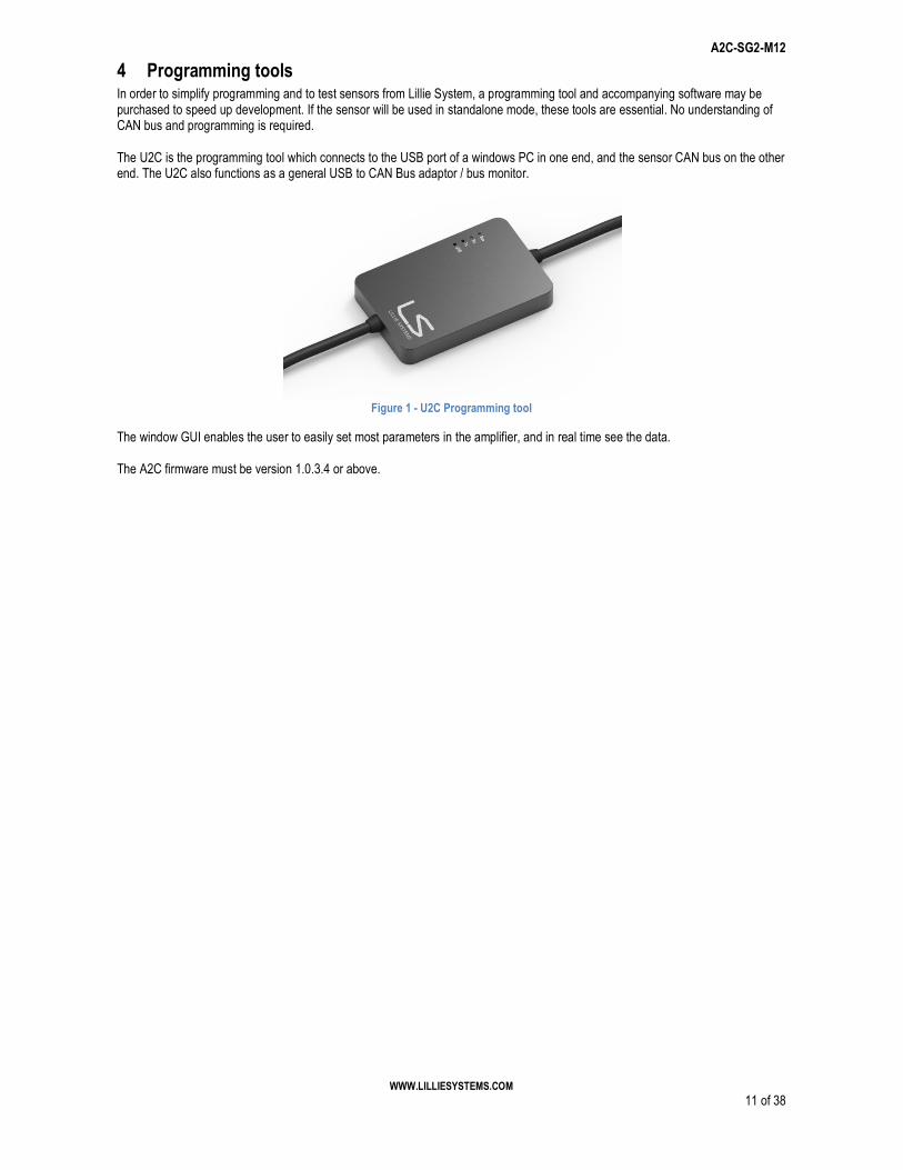
4 Programming tools In order to simplify programming and to test sensors from Lillie System, a programming tool and accompanying software may be purchased to speed up development. If the sensor will be used in standalone mode, these tools are essential. No understanding of CAN bus and programming is required. The U2C is the programming tool which connects to the USB port of a windows PC in one end, and the sensor CAN bus on the other end. The U2C also functions as a general USB to CAN Bus adaptor / bus monitor.
Figure 1 - U2C Programming tool
The window GUI enables the user to easily set most parameters in the amplifier, and in real time see the data. The A2C firmware must be version 1.0.3.4 or above.
A2C-SG2-M12
WWW.LILLIESYSTEMS.COM 12 of 38
5 Getting Started Things you will need:
1. A2C-SG2-M12 - strain gauge amplifier with CAN Bus 2. U2C - Programming tool 3. Strain gauge bridge 4. Power supply 5. Internet connection
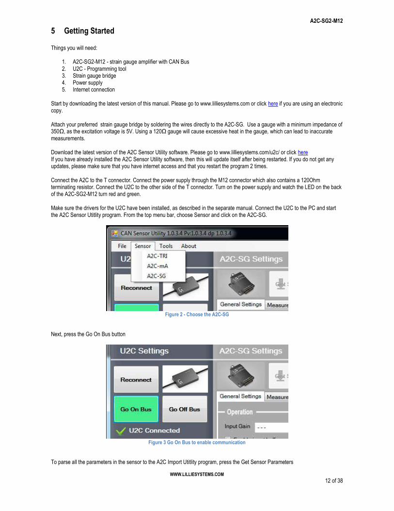
Start by downloading the latest version of this manual. Please go to www.lilliesystems.com or click here if you are using an electronic copy. Attach your preferred strain gauge bridge by soldering the wires directly to the A2C-SG. Use a gauge with a minimum impedance of 350Ω, as the excitation voltage is 5V. Using a 120Ω gauge will cause excessive heat in the gauge, which can lead to inaccurate measurements. Download the latest version of the A2C Sensor Utility software. Please go to www.lilliesystems.com/u2c/ or click here If you have already installed the A2C Sensor Utility software, then this will update itself after being restarted. If you do not get any updates, please make sure that you have internet access and that you restart the program 2 times. Connect the A2C to the T connector. Connect the power supply through the M12 connector which also contains a 120Ohm terminating resistor. Connect the U2C to the other side of the T connector. Turn on the power supply and watch the LED on the back of the A2C-SG2-M12 turn red and green. Make sure the drivers for the U2C have been installed, as described in the separate manual. Connect the U2C to the PC and start the A2C Sensor Utitlity program. From the top menu bar, choose Sensor and click on the A2C-SG.
Figure 2 - Choose the A2C-SG
Next, press the Go On Bus button
Figure 3 Go On Bus to enable communication
To parse all the parameters in the sensor to the A2C Import Utitlity program, press the Get Sensor Parameters
A2C-SG2-M12
WWW.LILLIESYSTEMS.COM 13 of 38
Figure 4 Get sensor parameters
If everything has been connected correctly, the parameters will be updated in the A2C Import Utility program.
Figure 5 ADC setup
To change a value, first change the value, followed by pressing the "Set Sensor Parameters" button. All the values changed will be sent to the A2C-SG. To save the values, so that the A2C-SG uses the values at start up, press the "Program Sensor" button. If this button is not press, the A2C-SG will use the previously saved values after a restart (power cycle). To view real time measurement values, click on the "Measurements" tab. Next click the "Start Receiving" button.
A2C-SG2-M12
WWW.LILLIESYSTEMS.COM 14 of 38
Figure 6 Measurements
The normal, min, max and mean values are displayed on the screen. If the update rate seems slow, then change the update interval (Tools - Options - General ). A value of 100ms or 50ms is suitable, but lower values are possible if the PC is powerful enough. To view a graph of the data, press the Ch 0 or Ch 1 check boxes, followed by the "Show Graph" button. The values displayed are the normal values. Figure 7 shows example data from a load cell being compressed and tensioned by hand.
Figure 7 Graphing data
A2C-SG2-M12
WWW.LILLIESYSTEMS.COM 15 of 38
6 Protocol It is important to understand the simple protocol before reading further. The first CAN byte is always the command. The second CAN byte is a sub-command. The remaining 6 CAN bytes are Data.
6.1 Protocol format Communication takes place over a CAN bus Interface The communication can use both 11-bit or 29bit frame format – CAN 2.0A / 2.0B.
RTR
DLC
Com
man
d
Sub
com
man
d
Dat
a 0
Dat
a 1
Dat
a 2
Dat
a 3
Dat
a 4
Dat
a 5
Bit length 1 4 8 8 8 8 8 8 8 8 Range
0 Al
way
s 0
1 - 8
0x00
– 0
xff
0x00
– 0
xff
0x00
– 0
xff
0x00
– 0
xff
0x00
– 0
xff
0x00
– 0
xff
0x00
– 0
xff
0x00
– 0
xff
Identifier: Default Identifier is set to 0x125 from factory, but can be changed as shown in 7.1.1 RTR: RTR is not used, so it must always be 0. DLC: DLC should be between 1 and 8. There is always at least one data byte as they are used as a commando word. Command: Command byte Sub Command: Sub command byte When data bytes are combined to form 16 or 32bit variables the big endian system is used.
A2C-SG2-M12
WWW.LILLIESYSTEMS.COM 16 of 38
7 Initial Setup The sensor comes with factory setting such as CAN filters, CAN Identifiers, bandwidth, mode etc. To prepare the sensor for operation some CAN settings might need to be changed. This is described in this section.
7.1 CAN Identifier The CAN Identifier is the identifier which the sensor sends when transmitting messages. The factory default value is 0x125. 7.1.1 Command: Set CAN ID To change the CAN ID to other values send the following message:
Command Sub Command Data[0] Data[1] Data[2] Data[3] Data[4] Data[5] 0x68 STD_EXT ID MSB ID ID ID LSB DLC = 0x06 (values above 0x06 are also valid, but Data bytes are not used)
STD_EXT:
0x01 = CAN Standard ID (11bit identifier) 0x02 = CAN Extended ID (29bit identifier)
ID: This is the CAN Identifier that the sensor uses when transmitting data, sent at an unsigned 32bit integer
[0x000 – 0x7FF] for CAN Standard ID (11bit identifier). Data[0] and Data[1] must both be 0x00! [0x00000000 – 1FFFFFFF] for CAN Extended ID (29bit identifier)
7.1.2 Command: Get Standard CAN ID
Command Sub Command Data[0] Data[1] Data[2] Data[3] Data[4] Data[5] 0xE8 Any value DLC = 0x02 (values above 0x02 are also valid, but Data bytes are not used)
Reply
Command Sub Command Data[0] Data[1] Data[2] Data[3] Data[4] Data[5] 0xE8 STD_EXT ID MSB ID ID ID LSB DLC = 0x06
The reply format follows the same format as setting the CAN ID as seen in 7.1.1
7.2 Baud rate The Baud rate is the communication speed on the CAN bus. It can be set to predefined values or to a custom value. The maximum CAN bus cable length is dependent on the baud rate. In general, bus speed of 1 Mega bits is used up to 40m, 500kbits/sec up to 100m, 250kbits/sec up to 250m and 50kbits/sec up to 1000m. These values can vary. Please read additional information on the internet about CAN bus speed and cable lengths. 7.2.1 Command: Set baud rate The default baud rate from the factory is 500kbits/s. To change the baud rate to another value send the following message:
0x01 = 1 Mega bits / second 0x02 = 500 Kilo bits / second 0x03 = 250 Kilo bits / second 0x04 = 125 Kilo bits / second 0x05 = 100 Kilo bits / second 0x06 = 50 Kilo bits / second 0x07 = Reserved for future use 0x08 = Reserved for future use 0x09 = Custom Baud rate.
AUTOTRANS: Enable / disable automatic re-transmission on CAN bus
0x00 = No automatic retransmission
A2C-SG2-M12
WWW.LILLIESYSTEMS.COM 17 of 38
0x01 = Automatic retransmission In addition of the BAUD and AUTOTRANS values, the data bytes 2 to 5 must contain the chars as shown in 7.2.1. This is to some degree prevent the baud rate to change and cause a CAN bus error if the filters are set incorrectly. 7.2.2 Command: Get baud rate To get the current baud rate
Command Sub Command Data[0] Data[1] Data[2] Data[3] Data[4] Data[5] 0xE7 DLC = 0x01 (values above 1 are also valid, but Data bytes are not used)
Reply
Command Sub Command Data[0] Data[1] Data[2] Data[3] Data[4] Data[5] 0xE7 BAUD AUTOTRANS Not defined DLC = 0x04
The reply format follows the same format as seen in 7.2.1
7.3 Custom baud rate The following values must be calculated first.
𝑇1 =32 × 10
𝐵𝑎𝑢𝑑 𝑟𝑎𝑡𝑒 × 𝑃𝑅𝐸𝑆
𝑩𝑺𝟏 = 𝑇1 × 𝑆𝑎𝑚𝑝𝑙𝑒 𝑃𝑜𝑖𝑛𝑡 − 1, 𝑚𝑢𝑠𝑡 𝑏𝑒 𝑙𝑒𝑠𝑠 𝑡ℎ𝑎𝑛 16
𝑩𝑺𝟐 = 𝑇1 − 𝐵𝑆1 − 1, 𝑚𝑢𝑠𝑡 𝑏𝑒 𝑙𝑒𝑠𝑠 𝑡ℎ𝑎𝑛 8
Example: Generate baud rate of 62.5kbits / second: We first select a prescale (PRES) value that creates an even T1 number. 32 is selected. The sample point is chosen to be 75%
7.3.1 Command: Set custom baud rate From the above calculations we can now send the following message.
Command Sub Command Data[0] Data[1] Data[2] Data[3] Data[4] Data[5] 0x54 0x01 SJW BS1 BS2 PRES_MSB PRES_LSB DLC = 0x07 (values above 7 are also valid, but Data bytes are not used)
SJW: Resynchronization Jump Width, Specifies the maximum number of time quanta the CAN hardware is allowed to lengthen or shorten a bit to perform resynchronization. This parameter can be a value of:
0x00 = 1 time quantum 0x01 = 2 time quantums 0x02 = 3 time quantums 0x03 = 4 time quantums
BS1: Specifies the number of time quanta in Bit Segment 1. This parameter can be a value of
0x00 = 1 time quantum 0x01 = 2 time quantums … 0x0F = 16 time quantums
BS2: Specifies the number of time quanta in Bit Segment 2. This parameter can be a value of
0x00 = 1 time quantum 0x01 = 2 time quantums …
A2C-SG2-M12
WWW.LILLIESYSTEMS.COM 18 of 38
0x07 = 8 time quantums PRES_MSB: Specifies the MSB prescale value PRES_LSB: Specifies the LSB prescale value 7.3.2 Command: Get custom baud rate To get the current baud rate
Command Sub Command Data[0] Data[1] Data[2] Data[3] Data[4] Data[5] 0xC3 Any value SJW BS1 BS2 PRES_MSB PRES_LSB DLC = 0x01 (values above 1 are also valid, but Data bytes are not used)
Reply
Command Sub Command Data[0] Data[1] Data[2] Data[3] Data[4] Data[5] 0xC3 Value sent SJW BS1 BS2 PRES_MSB PRES_LSB DLC = 0x02
The reply format follows the same format as seen in 7.3.1
7.4 CAN Filters The sensor will only respond to values which have passed through its CAN message filters. This means that many similar sensors can be attached to the same CAN network and by defining filters, only the sensor nodes which filter matches the CAN ID will interpret the message. There are two types of filters; standard filters which are unsigned 16bit integers and used for 11 bit identifiers, and extended filters which are unsigned 32 bit integers and used for 29bit identifiers. There are 4 standard filters and 2 extended filters. The standard filters only allow a message with the same ID as the filter value to pass through. From the factory settings the filters are configured as follows:
Standard Filter 1 = 1000 Standard Filter 2 = 1001 Standard Filter 3 = 1002 Standard Filter 4 = 1003 Extended Filter 1 = 0 Extended Filter 2 = 0
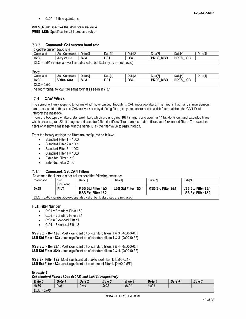
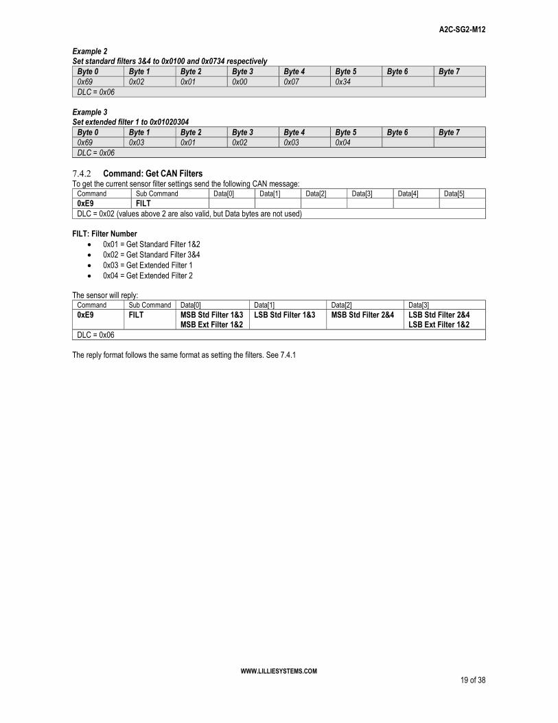
7.4.1 Command: Set CAN Filters To change the filters to other values send the following message:
DLC = 0x06 (values above 6 are also valid, but Data bytes are not used) FILT: Filter Number
0x01 = Standard Filter 1&2 0x02 = Standard Filter 3&4 0x03 = Extended Filter 1 0x04 = Extended Filter 2
MSB Std Filter 1&3: Most significant bit of standard filters 1 & 3. [0x00-0x07] LSB Std Filter 1&3: Least significant bit of standard filters 1 & 3. [0x00-0xFF] MSB Std Filter 2&4: Most significant bit of standard filters 2 & 4. [0x00-0x07] LSB Std Filter 2&4: Least significant bit of standard filters 2 & 4. [0x00-0xFF] MSB Ext Filter 1&2: Most significant bit of extended filter 1. [0x00-0x1F] LSB Ext Filter 1&2: Least significant bit of extended filter 1. [0x00-0xFF] Example 1 Set standard filters 1&2 to 0x0123 and 0x01C1 respectively
The reply format follows the same format as setting the filters. See 7.4.1
A2C-SG2-M12
WWW.LILLIESYSTEMS.COM 20 of 38
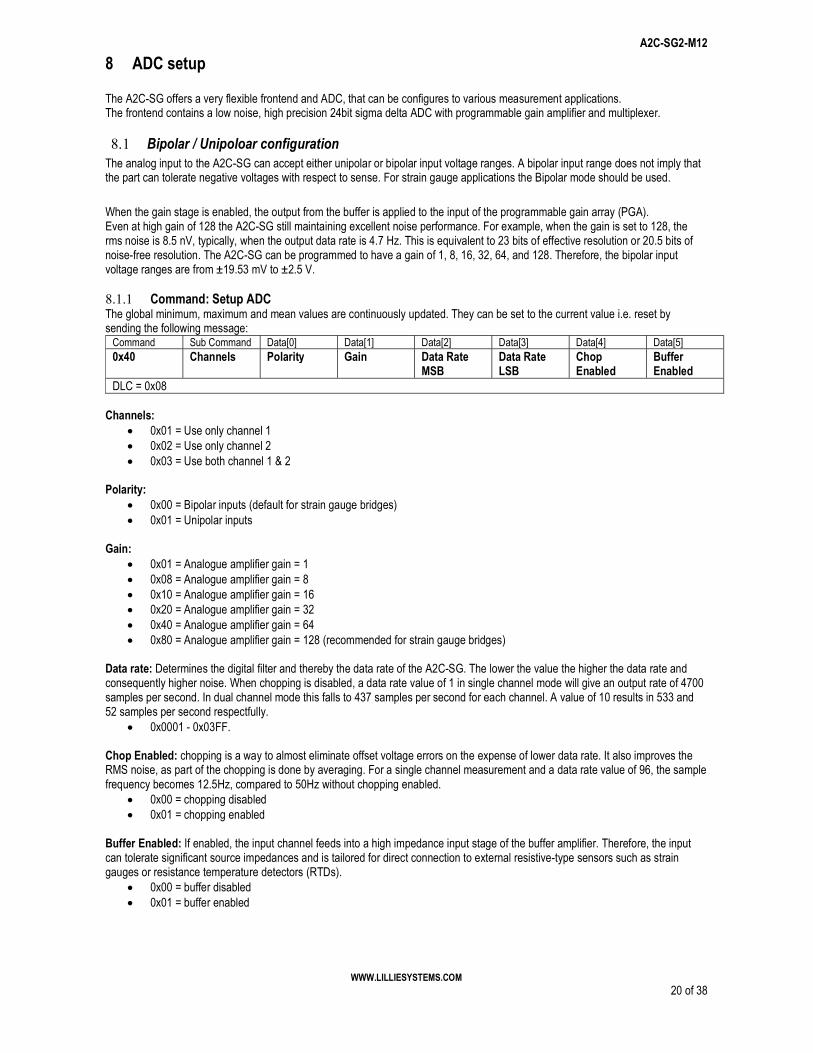
8 ADC setup The A2C-SG offers a very flexible frontend and ADC, that can be configures to various measurement applications. The frontend contains a low noise, high precision 24bit sigma delta ADC with programmable gain amplifier and multiplexer.
8.1 Bipolar / Unipoloar configuration The analog input to the A2C-SG can accept either unipolar or bipolar input voltage ranges. A bipolar input range does not imply that the part can tolerate negative voltages with respect to sense. For strain gauge applications the Bipolar mode should be used.
When the gain stage is enabled, the output from the buffer is applied to the input of the programmable gain array (PGA). Even at high gain of 128 the A2C-SG still maintaining excellent noise performance. For example, when the gain is set to 128, the rms noise is 8.5 nV, typically, when the output data rate is 4.7 Hz. This is equivalent to 23 bits of effective resolution or 20.5 bits of noise-free resolution. The A2C-SG can be programmed to have a gain of 1, 8, 16, 32, 64, and 128. Therefore, the bipolar input voltage ranges are from ±19.53 mV to ±2.5 V. 8.1.1 Command: Setup ADC The global minimum, maximum and mean values are continuously updated. They can be set to the current value i.e. reset by sending the following message:
Command Sub Command Data[0] Data[1] Data[2] Data[3] Data[4] Data[5] 0x40 Channels Polarity Gain Data Rate
MSB Data Rate LSB
Chop Enabled
Buffer Enabled
DLC = 0x08 Channels:
0x01 = Use only channel 1 0x02 = Use only channel 2 0x03 = Use both channel 1 & 2
0x01 = Analogue amplifier gain = 1 0x08 = Analogue amplifier gain = 8 0x10 = Analogue amplifier gain = 16 0x20 = Analogue amplifier gain = 32 0x40 = Analogue amplifier gain = 64 0x80 = Analogue amplifier gain = 128 (recommended for strain gauge bridges)
Data rate: Determines the digital filter and thereby the data rate of the A2C-SG. The lower the value the higher the data rate and consequently higher noise. When chopping is disabled, a data rate value of 1 in single channel mode will give an output rate of 4700 samples per second. In dual channel mode this falls to 437 samples per second for each channel. A value of 10 results in 533 and 52 samples per second respectfully.
0x0001 - 0x03FF. Chop Enabled: chopping is a way to almost eliminate offset voltage errors on the expense of lower data rate. It also improves the RMS noise, as part of the chopping is done by averaging. For a single channel measurement and a data rate value of 96, the sample frequency becomes 12.5Hz, compared to 50Hz without chopping enabled.
0x00 = chopping disabled 0x01 = chopping enabled
Buffer Enabled: If enabled, the input channel feeds into a high impedance input stage of the buffer amplifier. Therefore, the input can tolerate significant source impedances and is tailored for direct connection to external resistive-type sensors such as strain gauges or resistance temperature detectors (RTDs).
0x00 = buffer disabled 0x01 = buffer enabled
A2C-SG2-M12
WWW.LILLIESYSTEMS.COM 21 of 38
Example 1 Setup ADC for a strain gauge bridge on both channels, with chop and buffer enabled and 10Hz sample rate for each channel. The data rate is set to 30 - 0x001E
DLC = 0x08 Example 2 Setup ADC for a strain gauge bridge on both channels, with chop and buffer enabled and 0.5Hz sample rate for each channel. The data rate is set to 605 - 0x025D
Command Sub Command Data[0] Data[1] Data[2] Data[3] Data[4] Data[5] 0x0C Channels Polarity Gain Data Rate
MSB Data Rate LSB
Chop Enabled
Buffer Enabled
DLC = 0x08 The format follows the same as for sending parameters by command 0x40
8.1.3 A note on data rate and data requested If the data rate has a high value, this will result in longer sampling times. Data requested on the CAN Bus between samples will return the last sampled value. To overcome this problem, the periodic messages can be setup, so that a CAN message is sent when the ADC has a new sample ready. Changing the data rate then directly change the frequency of the CAN Bus messages.
A2C-SG2-M12
WWW.LILLIESYSTEMS.COM 22 of 38
9 Excitation voltage selection setup The A2C-SG offers a selectable excitation voltage of 2.5V or 5V 9.1.1 Set excitation voltage:
Command Sub Command Data[0] Data[1] Data[2] Data[3] Data[4] Data[5] 0x41 Voltage DLC = 0x02
Voltage:
0x00 = Use 5V excitation
0x01 = Use 2.5V excitation 9.1.2 Get excitation voltage:
Command Sub Command Data[0] Data[1] Data[2] Data[3] Data[4] Data[5] 0xC6 Voltage DLC = 0x02
The format follows the same as for sending parameters by command 0x41
A2C-SG2-M12
WWW.LILLIESYSTEMS.COM 23 of 38
10 Getting measurement values The measurements from the amplifier can be sent in different formats, either as 24bit integers, 32bit integers or 32 bit floating point. There are currently 7 types of data available for each channel:
Current value RMS value Mean value Minimum value Maximum value Sync value Sync RMS value
All types are continuously available. The mean, minimum and maximum values are calculated since startup or since the command: " Reset Global Minimum, Maximum and Mean values" is received - see section: 10.1.4. 10.1.1 Command: Get both Send this command:
Command Sub Command Data[0] Data[1] Data[2] Data[3] Data[4] Data[5] 0x0A RET DLC = 0x02 (values above 0x02 are also valid, but Data bytes are not used)
RET: determines if current values or a previous synced value is used
0x00 = Get current values, which are continuously updated 0x01 = Get a previously synced value. Please see the Sync command in section 0x02 = Get the minimum values 0x03 = Get the maximum values 0x04 = Get the mean values 0x05 = Get the RMS values 0x06 = Get the previously synced RMS values
After the 0x0A and a sub command have been received, the sensor will return the measurements for both channels as two 24bit signed integers. The RET value applies to both channels at the same time. Reply:
Command Sub Command Data[0] Data[1] Data[2] Data[3] Data[4] Data[5] 0x0A Value sent is
returned Ch1 MSB Ch1 Ch1 LSB Ch2 MSB Ch2 Ch2 LSB
DLC = 0x08 10.1.2 Command: Get configurable channel measurements Send this command:
Command Sub Command Data[0] Data[1] Data[2] Data[3] Data[4] Data[5] 0x0B Channel Return type Value type DLC = 0x04
Channel: is the channel number that is requested and must be one of the following values
0x00 = channel 1 0x01 = channel 2
Return type: is the data type returned:
0x00 = signed int - 4 bytes 0x01 = float - 4 bytes
Value type: is the requested value and must be one of the following values
0x00 = current measurement 0x01 = synced measurement 0x02 = minimum value 0x03 = maximum value
A2C-SG2-M12
WWW.LILLIESYSTEMS.COM 24 of 38
0x04 = mean value 0x05 = RMS value 0x06 = synced RMS value
Reply:
Command Sub Command Data[0] Data[1] Data[2] Data[3] Data[4] Data[5] 0x0B Channel Return type Value type Channel X
MSB Channel X Channel X Channel X
LSB DLC = 0x08
10.1.3 Command: Get current channel measurements with math functions Send this command:
Command Sub Command Data[0] Data[1] Data[2] Data[3] Data[4] Data[5] 0x0C Return type Value type MATH DLC = 0x04 (values above 0x04 are also valid, but Data bytes are not used)
Return type: is the data type returned:
0x00 = signed int - 4 bytes 0x01 = float - 4 bytes
Value type: is the requested value and must be one of the following values
0x00 = current measurement 0x01 = synced measurement 0x02 = minimum value 0x03 = maximum value 0x04 = mean value 0x05 = RMS value 0x06 = synced RMS value
MATH: is the requested math operation and must be one of the following values
0x00 = No math is performed 0x01 = Add channel 1 to channel 2 0x02 = Subtract channel 2 from channel 1 0x03 = Divide channel 2 with channel 1 0x04 = Multiply channel 1 with channel 2 0x05 = Subtract channel 1 from channel 2 0x06 = Divide channel 1 with channel 2
Reply:
Command Sub Command Data[0] Data[1] Data[2] Data[3] Data[4] Data[5] 0x0C Return type Value type MATH Math Result
MSB Math Result Math Result Math Result
LSB DLC = 0x08
10.1.4 Command: Reset Global Minimum, Maximum and Mean values The global minimum, maximum and mean values are continuously updated. They can be set to the current value i.e. reset by sending the following message:
Command Sub Command Data[0] Data[1] Data[2] Data[3] Data[4] Data[5] 0x0F VAL DLC = 0x02 (values above 0x02 are also valid, but Data bytes are not used)
VAL:
0x01 = Reset minimum, maximum and mean values for both input channels 0x02 = Reset minimum, maximum and mean values for input 1 0x03 = Reset minimum, maximum and mean values for input 2
10.1.5 Command: Set Integer Scaling Since the calibration and all internal data types use floating point data types, getting integers requires scaling. The scaling can be any integer value, which is then multiplied to the internal floating point, truncated and eventually sent on the CAN bus. The default scaling value is 10. This means that if the actual value is 8.76, then this value is multiplied by 10 and truncated, thus the value sent on the CAN bus will be 87. There is no rounding, so a sufficient high scaling factor must be used.
A2C-SG2-M12
WWW.LILLIESYSTEMS.COM 25 of 38
Command Sub Command Data[0] Data[1] Data[2] Data[3] Data[4] Data[5] 0x1E Channel Scaling MSB Scaling Scaling Scaling LSB DLC = 0x06 (values above 0x06 are also valid, but Data bytes are not used)
Channel: is the channel number that is requested and must be one of the following values
0x00 = channel 1 0x01 = channel 2
Scaling: Float to integer scaling
0x00 = unsigned int - 4 bytes Example 1 Set scaling to 1000 for channel 1 - send the following command
As with all other parameters, the parameters must be saved if they are to be used automatically at startup. 10.1.6 Command: Set CAN timeout This setting only applies to FFT sending
Command Sub Command Data[0] Data[1] Data[2] Data[3] Data[4] Data[5] 0x66 TO DLC = 0x02 (values above 2 are also valid, but Data bytes are not used)
TO: Timeout in ms. Default [0x20 = 32ms]
0x00 – 0xFF = timeout in ms that the sensor tries to send a message on the CAN Bus when sending the FFT. The timeout is independent of the baud rate. The timeout is also independent of the CAN bus fault system which will go off bus if the Transmit error counter reaches 255.
10.1.7 Command: Get CAN timeout
Command Sub Command Data[0] Data[1] Data[2] Data[3] Data[4] Data[5] 0xE6 DLC = 0x01 (values above 1 are also valid, but Data bytes are not used)
Reply
Command Sub Command Data[0] Data[1] Data[2] Data[3] Data[4] Data[5] 0xE6 TO DLC = 0x02
TO:
[0x00 – 0xFF] = Timeout in milliseconds 10.1.8 Command: Set wait period between CAN messages This setting only applies to FFT sending
Command Sub Command Data[0] Data[1] Data[2] Data[3] Data[4] Data[5] 0x65 WAIT DLC = 0x02 (values above 2 are also valid, but Data bytes are not used)
WAIT: Time in milliseconds between CAN messages. Default [0x00 = 0ms]
0x00 – 0xFF = The time the sensor will wait between CAN messages. This is to make sure that the host has time to process the information from the sensor, especially when sending multiple packages such as the FFT requests.
NB: Using a large WAIT value will effectively halt the sensor from doing other work while it is transmitting. The lowest possible value should be used. 10.1.9 Command: Get wait period between CAN messages
Command Sub Command Data[0] Data[1] Data[2] Data[3] Data[4] Data[5] 0xE5 DLC = 0x01 (values above 1 are also valid, but Data bytes are not used)
WAIT [0x00 – 0xFF] = Waiting time in milliseconds between CAN messages
A2C-SG2-M12
WWW.LILLIESYSTEMS.COM 27 of 38
11 Setting up Periodic Messages The strain gauge amplifier can be configured to send periodic CAN messages at a user specified time interval for each message. The messages that can be sent periodically are: Current measurements from both channels; Command: 0x0A Get configurable channel measurements; Command: 0x0B (sub commands 0x00, 0x01, 0x02) Get system mode (can be used as a heartbeat); Command: 0xC0 A maximum of 4 periodic messages can be setup at the same time – 4 tasks. Each message can be sent with an interval ranging from 2ms (500 messages per second) up to 65535ms. The CAN message that controls the periodic messages starts with the command byte (byte 0) which must be 0x52 followed by the subcommand (byte 1) which represents the message number. The message number is currently limited to a value of 1-4. Byte 2 is the state of the period message which can be 0x00 for Off or 0x01 for On. Byte 3 is the value of the command (0x0A, 0x0B, 0xC0) and Byte 4 is the value of the subcommand. The bytes 5 & 6 are the periodic interval. This is sent as an unsigned 16bit integer with a value between 2 and 65535. To turn Off a periodic message byte 2 must be set to 0x00. Note that when a periodic message is turned off, the command, sub-command and period values will not be updated and the values sent will be ignored. If the data rate is set to a high value, data might not be ready to send. Please see 8.1.3. 11.1.1 Command: Set Periodic Messages
Command Sub Command Data[0] Data[1] Data[2] Data[3] Data[4] Data[5] 0x52 MsgNbr State Cmd SubCmd TimeMSB TimeLSB DLC = 0x07 (values above 0x07 are also valid, but Data bytes are not used)
MsgNbr: Message number currently 1-4 State: 0x01 for ON, 0x00 for OFF Cmd: Command number SubCmd: Sub-command number TimeMSB: MSB of time period [0x00 – 0xFF] TimeLSB: LSB of time period [0x02 – 0xFF]
Example 1 Set periodic message number 1 to send heart beat every second
DLC = 0x07 An interval of 1 second is 1000ms = 0x03E8. MSB is sent first, then LSB. Example 2 Set periodic message number 2 to send RMS values for all channels at a rate of 100 times per second
DLC = 0x07 An interval of 100 times per second is a message every 10ms = 0x000A. MSB is sent first, then LSB. Example 3 Set periodic message number 3 to Off – stop sending this periodic message
If the above is sent, then bytes 3 to 6 will be discarded and not be changed in the sensor. To change these bytes, byte 2 must be set to 0x01.
A2C-SG2-M12
WWW.LILLIESYSTEMS.COM 28 of 38
11.1.2 Command: Set Periodic Messages Follow ADC Command Sub Command Data[0] Data[1] Data[2] Data[3] Data[4] Data[5] 0x57 VAL DLC = 0x02 (values above 0x02 are also valid, but Data bytes are not used)
VAL: Turns individual channels on/off:
0x00 = Turn off these periodic messages 0x01 = send a CAN message using a 32bit floating point type every time channel 1 finishes a conversion 0x02 = send a CAN message using a 32bit floating point type every time channel 2 finishes a conversion 0x03 = send a CAN message using a 32bit floating point type every time channel 1 or channel 2 finishes a conversion 0x04 = send a CAN message using a signed 32bit integer type every time channel 1 finishes a conversion 0x08 = send a CAN message using a signed 32bit integer type every time channel 2 finishes a conversion 0x0C = send a CAN message using a signed 32bit integer type every time channel 1 or channel 2 finishes a conversion
The returned data corresponds to data sent with command 0x0B - see section 10.1.2. For single channel measurement with the lowest filter value of 1, the maximum number of messages is capped at 2400 messages per second, whereas the actual sample rate of the ADC is 4800 messages per second. This is to prevent CAN bus overload.
11.2 J1939 type CAN Messages (only for 2 active channels) In this mode, each channel will have its own ID. Channel 1 will always be the same as the CAN Standard ID as set in 7.1.1, and channel 2 will always be one value higher. So if the CAN Standard ID is set to 293, then channel 1 will output using this ID, and channel 2 will use 294. Enabling J1939 type messages will override and the normal periiodic messages that follows the ADC (command 0x57) Only integer values are supported in this mode. The integer scaling is used as described in 10.1.5 11.2.1 Command: Set Periodic Messages to follow ADC - J1939 style
Command Sub Command Data[0] Data[1] Data[2] Data[3] Data[4] Data[5] 0x6E MODE DLC = 0x02 (values above 0x02 are also valid, but Data bytes are not used)
MODE:
0x00 = turn off J1939 type messages 0x01 = send a single CAN message containing the normal value of the ADC, using a signed 32bit integer type every time
channel 1 or 2 finishes a conversion 0x02 = send 3 CAN messages using a signed 32bit integer type every time channel 1 or 2 finishes a conversion. The first
message contains the normal values, the second contains the minimum value, and the third contains the maximum value 0x03 =
Output:
Data[0] Data[1] Data[2] Data[3] Data[4] Ch1 MSB Ch1 Ch1 Ch1 LSB Value type DLC = 0x05
Value type: is the requested value and must be one of the following values
0x00 = current measurement 0x02 = minimum value 0x03 = maximum value
11.2.2 Command: Get Periodic Messages to follow ADC - J1939 style Send this command:
Command Sub Command Data[0] Data[1] Data[2] Data[3] Data[4] Data[5] 0x6F DLC = 0x01 (values above 0x01 are also valid, but Data bytes are not used)
Reply:
Command Sub Command Data[0] Data[1] Data[2] Data[3] Data[4] Data[5] 0x6F VAL DLC = 0x02
A2C-SG2-M12
WWW.LILLIESYSTEMS.COM 29 of 38
VAL returns 0x00 / 0x01 / 0x02 - as described for the Set command 0x6E
A2C-SG2-M12
WWW.LILLIESYSTEMS.COM 30 of 38
12 Calibrating The strain gauge amplifier is calculated without using any units. A high and low value is required. This can be a strain gauge excitation, a millivolt signal etc. The easiest way is to use the U2C and the A2C Sensor Utility. For most accurate calibration, the signal should be held steady for 1 second, before and after the measurement is taken by the sensor. 12.1.1 Command: Calibrate input channels using floating point data
Command Sub Command
Data[0] Data[1] Data[2] Data[3] Data[4] Data[5]
0x20 Channel Data MSB Data Data Data LSB High/Low 0x80 DLC = 0x08
0x00 = Low value of calibration data 0x01 = High value of calibration data
Example 1 Using 2 point calibration on channel 1, low value of 0.0f and high value of 500.0f A float with a value of 0.0f will be all zeroes (data bytes 2-5)
DLC = 0x08 Make sure to save the calibration constants using command 0x21. See 14.1.1
13 Set Factory Calibration Values There are no factory calibration stored in the amplifier.
14 Save Current Calibration Constants After changing calibration constants in the sensor, these constants will remain unchanged until the sensor is reset. By saving the current calibration constants to the sensor, these will be loaded at start-up. The saved values does not include the other parameters in the sensor, which can be saved using the command in section 16 NB: Since the calibration constants are stored in FLASH memory which have a limited number of erase / write cycles, the user must ensure that this command is not called more than 10.000 times within the sensor’s lifetime. 14.1.1 Command: Save Current Calibration Constants Issue the following command to save the current calibration constants:
Command Sub Command
Data[0] Data[1] Data[2] Data[3] Data[4] Data[5]
0x21 0xFF DLC = 0x02 (values above 2 are also valid, but Data bytes are not used)
A2C-SG2-M12
WWW.LILLIESYSTEMS.COM 32 of 38
15 Getting Sensor Information The sensor information can be requested at any time. The following information can be sent from the sensor:
Sensor Serial Number Firmware Number Hardware Revision Sensor Type Firmware Number - Bootloader
15.1.1 Command: Get sensor information Send this command to sensor:
Command Sub Command Data[0] Data[1] Data[2] Data[3] Data[4] Data[5] 0xEF INFOTYPE DLC = 0x02 (values above 2 are also valid, but Data bytes are not used)
INFOTYPE:
0x01 to 0x03 = reserved 0x04 = Firmware Number, is the version of the software in the sensor 0x05 = reserved 0x06 = Sensor Type, a number specifying the type of sensor. 0x14 = Serial number (same as is laser engraved on the sensor) 0x30 = Internal Temperature ( starting from firmware version 2.65 )
After this command has been received, the sensor will return requested information as an unsigned 32bit integer Reply:
Command Sub Command Data[0] Data[1] Data[2] Data[3] Data[4] Data[5] 0xEF INFOTYPE INFO_MSB INFO INFO INFO_LSB DLC = 0x06
A2C-SG2-M12
WWW.LILLIESYSTEMS.COM 33 of 38
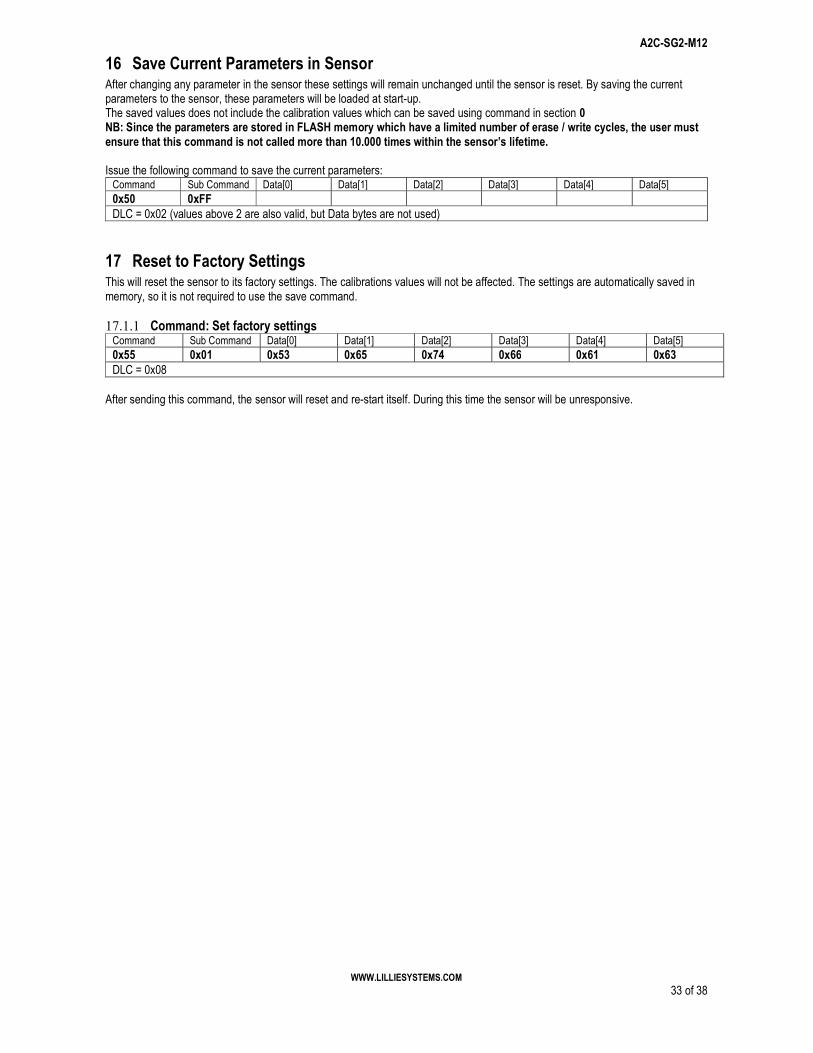
16 Save Current Parameters in Sensor After changing any parameter in the sensor these settings will remain unchanged until the sensor is reset. By saving the current parameters to the sensor, these parameters will be loaded at start-up. The saved values does not include the calibration values which can be saved using command in section 0 NB: Since the parameters are stored in FLASH memory which have a limited number of erase / write cycles, the user must ensure that this command is not called more than 10.000 times within the sensor’s lifetime. Issue the following command to save the current parameters:
Command Sub Command Data[0] Data[1] Data[2] Data[3] Data[4] Data[5] 0x50 0xFF DLC = 0x02 (values above 2 are also valid, but Data bytes are not used)
17 Reset to Factory Settings This will reset the sensor to its factory settings. The calibrations values will not be affected. The settings are automatically saved in memory, so it is not required to use the save command. 17.1.1 Command: Set factory settings
After sending this command, the sensor will reset and re-start itself. During this time the sensor will be unresponsive.
A2C-SG2-M12
WWW.LILLIESYSTEMS.COM 34 of 38
18 Recommended settings to get started Example 1 Setup ADC for a strain gauge bridge on both channels, with chop and buffer enabled and 10Hz sample rate for each channel. The data rate is set to 30 - 0x001E and is sent on the CAN Bus every time an ADC finishes a sample Set integer scaling to 10000 for channel 1
19 Updating Sensor Firmware The sensor firmware can be updated over the CAN bus by using the U2C programmer. New updates are continuously made available when new functionality is added or improvements are made. Please visit www.lilliesystems.com to check for updates and the latest version of this manual. Should you be interested in updating the firmware using your own CAN device, please contact us for a description of the protocol, and NDA, which must be signed prior to receiving the protocol.
A2C-SG2-M12
WWW.LILLIESYSTEMS.COM 36 of 38
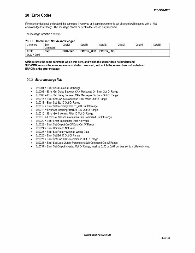
20 Error Codes If the sensor does not understand the command it receives or if some parameter is out of range it will respond with a “Not acknowledged” message. This message cannot be sent to the sensor, only received. The message format is a follows 20.1.1 Command: Not Acknowledged
Command Sub Command
Data[0] Data[1] Data[2] Data[3] Data[4] Data[5]
0xFE CMD SUB-CMD ERROR_MSB ERROR_LSB DLC = 0x05
CMD: returns the same command which was sent, and which the sensor does not understand SUB-CMD: returns the same sub-command which was sent, and which the sensor does not undertand. ERROR: Is the error message
20.2 Error message list:
0x0001 = Error Baud Rate Out Of Range. 0x000B = Error Get Delay Between CAN Messages On Error Out Of Range 0x000C = Error Set Delay Between CAN Messages On Error Out Of Range 0x0017 = Error Set CAN Custom Baud Error Mode Out Of Range 0x0018 = Error Set Std ID Out Of Range 0x0019 = Error Set IncomingFilterID1_2ID Out Of Range 0x001A = Error Set IncomingFilterID3_4ID Out Of Range 0x001C = Error Get Incoming Filter ID Out Of Range 0x001D = Error Get Sensor Information Sub Command Out Of Range 0x0022 = Error Enter Boot loader Data Not Valid 0x0023 = Error Set Output On Off Data Out Of Range 0x0024 = Error Command Not Valid 0x0025 = Error Set Factory Settings Wrong Data 0x0026 = Error Set Ext ID Out Of Range 0x0027 = Error Set CAN ID Sub command Out Of Range 0x0028 = Error Set Logic Output Parameters Sub Command Out Of Range. 0x0034 = Error Set Output Inverted Out Of Range, must be 0x00 or 0x01 but was set to a different value.
A2C-SG2-M12
WWW.LILLIESYSTEMS.COM 37 of 38
A2C-SG2-M12
WWW.LILLIESYSTEMS.COM 38 of 38
IMPORTANT NOTICE
Lillie Systems reserve the right to make corrections, enhancements, improvements and other changes to its products (sometimes referred to as components) and services without prior notice. Buyers should obtain the latest relevant information before placing orders and should verify that such information is current and complete. All products are sold subject to Lillie Systems’ terms and conditions of sale supplied at the time of order acknowledgment. Lillie Systems warrants performance of its products (components) to the specifications applicable at the time of sale, in accordance with the warranty in Lillie System’s terms and conditions of sale. Testing and other quality control techniques are used to the extent that Lillie Systems deems necessary to support this warranty. Except where mandated by applicable law, testing of all parameters of each component is not necessarily performed. Lillie Systems assumes no liability for applications assistance or the design of Buyers’ products. Buyers are responsible for their products and applications using Lillie System components. To minimize the risks associated with Buyers’ products and applications, Buyers should provide adequate design and operating safeguards. Buyer acknowledges and agrees that it is solely responsible for compliance with all legal, regulatory and safety-related requirements concerning its products, and any use of Lillie Systems’ components in its applications, notwithstanding any applications-related information or support that may be provided by Lillie Systems. Buyer represents and agrees that it has all the necessary expertise to create and implement safeguards which anticipate dangerous consequences of failures, monitor failures and their consequences, lessen the likelihood of failures that might cause harm and take appropriate remedial actions. Buyer will fully indemnify Lillie Systems and its representatives against any damages arising out of the use of any Lillie Systems components in safety-critical applications. Lillie Systems products may be promoted specifically to facilitate safety-related applications. With such components, Lillie Systems’ goal is to help customers design and create their own end-product solutions that meet applicable functional safety standards and requirements. Nonetheless, such components are subject to these terms.


![WR *+] G% '/9$ ZLWK )L[HG Q6 3XOVHG 2XWSXW 2G4G... · 2017. 12. 18. · orj ylghr dpsolilhu '/9$ wkdw rshudwhv ehwzhhq wkh wr *+] iuhtxhqf\ udqjh ,w kdv d g\qdplf udqjh ri g% d orj](https://static.documents.pub/doc/80x56/60945e222de28f4c837972c8/wr-g-9-zlwk-lhg-q6-3xovhg-2xwsxw-2g4g-2017-12-18-orj-ylghr-dpsolilhu.jpg)
![7:2 3267 /,)7 0RGHO %3 · )/2253/$7( &+$,1 '5,9( 7:2 3267 /,)7 0rgho ; 6hh )lj 'xdo k\gudxolf f\olqghuv ghvljqhg dqg pdgh dv vwdqgdugv xwlol]lqj rlo vhdo lq f\olqghu 6hoi oxeulfdwlqj](https://static.documents.pub/doc/80x56/5e72e1dc3f93d211642a0bfa/72-3267-7-0rgho-3-22537-1-59-72-3267-7-0rgho-6hh-lj.jpg)


![3LHUUH 9LOODUV DQG .DULQ &HQ]XDO HGLWRUV · 7ho )d[ ( pdlo lqir#fu\vwdolpsdfw frp kwwsv zzz fu\vwdolpsdfw gh &5](https://static.documents.pub/doc/80x56/605fd8e5d027eb0bc4721335/3lhuuh-9looduv-dqg-dulq-hqxdo-hglwruv-7ho-d-pdlo-lqirfuvwdolpsdfw-frp.jpg)