1 XII PHYSICS RBSE – FLASHBACK 2015 Time: 3.15 Hrs. Max. Marks: 56 Q.1 Write the statement of Gauss‟s law. A.1 It states that the net electric flux diverging normally form a closed surface is equal to 0 1 times the net charge enclosed by the surface i.e., 0 S 1 E.dS q Q.2 Calculate the potential at a point due to a charge of 4 × 10 –9 C located 9 × 10 –2 m away from it. A.2 o 1 Q Potential, V 4 r 9 2 9 9 2 Q 4 10 C r 9 10 m (9 10 4 10 ) V 9 10 V= 400V Q.3 In the figure, resistivities of two conductors of same material are 1 m and 2 m respectively. Write the value of ratio of 1 and 2 [1] A.3 1 2 1 1 : 1 (as for same material, 1 2 ) Q.4 Write average value of current over a complete cycle of alternating current. A.4 Zero Q.5 Write the name of electromagnetic wave produced by vacuum tube magnetron. A.5 Microwaves Q.6 Write the relation between object distance (u), image distance () and focal length (f) for a concave mirror. A.6 1 1 1 u f Q.7 (a) Write the name of the lens used to correct near sightedness (myopia). (b) What will be the radius of curvature of a concave mirror of focal length 10 cm? A.7 (a) Diverging lens (Concave) (b) R = 2f
Define mass defect of a nucleus. Binding energy of 16
8 O is 127.5 MeV. Write the value of its
binding energy per nucleon. Write the value of 1 eV energy in joule.
A.21 Half life of a radioactive substance−The time in which the quantity of undecayed nuclei of a
radioactive substance remains half is called the half life of that substance. It is denoted by T.
(a) Relation between half life and decay constant− If in the beginning is (is at time t = 0), the
number of atoms of a radioactive substance is N0 then after time t the number of atoms
remaining i.e., number of undecayed nuclei,
N= N0e-λt
If the half- life of a substance is T then at t = T1/2
0N
N2
00
tNN .
2e
Or 1/2T1e
2
Or 1/2T
12
e
Or 1/2T2 e
Or 1/2T
e elog 2 log e
Or e 1/2log 2 T
7
e1/2
log 2 0.693T
(b) Relation between half life and mean life.
Half- life 1/2
0.693T
a
1Mean lifeT
1/2 aT 0.693T
OR
Mass defect of nucleus−The actual mass of the product is always less than its constituents i.e. the
combined mass of the nucleus. This difference in the mass is called mass- defect of a nucleus. So
mass defect can be obtain by mass of nucleus obtained from calculation−actual mass of the
nucleus.
or M m M
Here mass of nucleus obtained from calculation is represented by m and actual mass of the
nucleus is denotes by M.
Binding Energy, bE =127.5MeV
Binding Energy per nucleon
bbnE
A
E
Binding Energy per nucleus, A = 16.
bn
127.5E V
16Me
V7.96Me
191eV 1.6 10 J
Q.22 On the basis of Bohr‟s postulates derive an expression for orbital velocity of an electron in nth
stationary orbit of hydrogen atom.
The ground state energy of hydrogen atom is (–) X eV. What will be the kinetic energy of the
electron in this state?
A.22 Orbital velocity−
First postulate 2 2
2
mv ke
r r …(1)
Second postulate 2
nhmvr …(2)
From(1) and(2)
2 2
2
2
mv ke
r rnhmvr
2
2 2
.2
v ke
r r nh
22
kev
nh
Kinetic Energy,
K= −E
8
E= −X
K= −X
Q.23 (a) NAND gate are also called universal gate. Why?
(b) Draw a logic symbol of OR gate.
(c) Write the value of output y in the given circuit:
(d) Write the name of the diode used in voltage regulation.
A.23 (a) NAND gate are also called universal gates because they can be used to realize any logic gate.
(b)
(c) Given gate is a NOT gate.
1, 0. For a y
(d) Zener Diode
Q.24 Explain briefly the following terms used in communication system:
(a) modulation, and (b) transducer.
A.24 (a) Modulation− The process of change the signal of original message or information in such a
way that it can be transmitted to far and wide places is called modulation. In this can be
transmitted to far and superimposed over the high frequency carrier signal. Two types of
modulation are (i) Amplitude modulation (Analog and Digital) (ii) Frequency modulation.
(b) Transducer− Any advice that converts one form of energy into another is called transducer.
An electrical transducer converts some physical variable like pressure, temperature,
displacement etc. into corresponding variation‟s in the electric signal at its output.
Q.25 Match the following:
(i) Resonant frequency (a) 1
LC
(ii) Quality factor (b) 0L
R
(iii) Average power (c) VI cos
(iv) Impedance (d) 2 2
L CR (X X )
(v) Magnetic potential energy (e) 21Li
2
(vi) Coefficient of self-induction (f) E
dI
dt
9
A.25 Match the following:
(i) Resonant frequency (a) VI cos
(ii) Quality factor (b) 21Li
2
(iii) Average power (c) 1
LC
(iv) Impedance (d) 2 2
L CR (X X )
(v) Magnetic potential energy (e) E
dI
dt
(vi) Coefficient oif self-induction (f) 0L
R
Q.26 Define the following:
(a) Total internal reflection
(b) Diffraction of light
(c) Refraction of light
A.26 (a) Total internal reflection−The phenomenon in which a ray of light travelling at an angle of
incidence greater than the critical angle from denser to a rarer medium is totally reflected
back into the denser medium is called total internal reflection.
(b) Diffraction of light− The phenomenon of bending of light around the corner of small
obstacles and its consequent spreading into the regions of geometrical shadow is called
diffraction of light.
(c) Refraction of light – The phenomenon of the change in the path of light as it passes
obliquely from one transparent medium to another called refraction of light.
Q.27 Define common emitter output characteristic for a transistor.
Draw a circuit diagram for studying the characteristics of n-p-n transistor in common emitter
configuration.
Among emitter, base and collector regions of a transistor which one is (a) largest in size and (b) most
heavily doped?
OR
Define rectification.
Draw circuit diagram of a full-wave rectifier.
Semi-conductor related to given energy band diagram is:
n-type semi-conductor, p-type semi-conductor or intrinsic semi-conductor.
10
A.27
Output Characteristics – A graph showing variation of collector current IC with collector –
emitter voltage VCE at constant base current IB is called output characteristic of transistor.
Study of these curve show following features− (i) Large the value of IB, large is the value of IC for the given VCE.
(ii) When voltage VCE increase from O to about 0.5 V, collector current increase rapidly, This
value of VCE is called Knee voltage.
(iii) Once the voltage VCE exceeds voltage VBE, the output current IC varies vary slowly but
linearly with VCE for a given base current IB.
(a) Collector is largest in size.
(b) Emitter is heavily doped
OR
Rectification– Conversion of ac into dc using a rectifier is called rectification.
A full wave rectifier is consists of a transformer, two junction diodes D1 and D2 and load resistance
RL. The input ac signal is fed to the primary coil P of a transformer.
The two ends A and B of the secondary is tapped at central point T which is P–ends of two diodes
through load resistance RL.
Given energy band diagram is of n–type semiconductor as the impurity energy level is near
conduction band.
Given energy band diagram is of n- type semiconductor as the impurity energy level is near
conduction band.
11
Q.28 (a) Derive a relation for electric field due to an electric dipole at a point on the equatorial plane
of the electric dipole. Draw necessary diagram.
(b) An electric dipole of charge 1 C exists inside a spherical Gaussian surface of radius 1
cm. Write the value of outgoing flux from the Gaussian surface.
(c) Potential on the surface of a charged spherical shell of radius 10 cm is 10V. Write the value
of potential at 5 cm from its centre.
OR
(a) Obtain a relation for equivalent capacitance of the series combination of capacitors. Draw a
circuit diagram.
(b) 10 capacitors each of capacity 10 F are joined first in series and then in parallel. Write the
value of product of equivalent capacitances.
(c) What will be the value of capacitance of a 4 F capacitor if a dielectric of dielectric constant
2 is inserted fully between the plates of parallel plate capacitor?
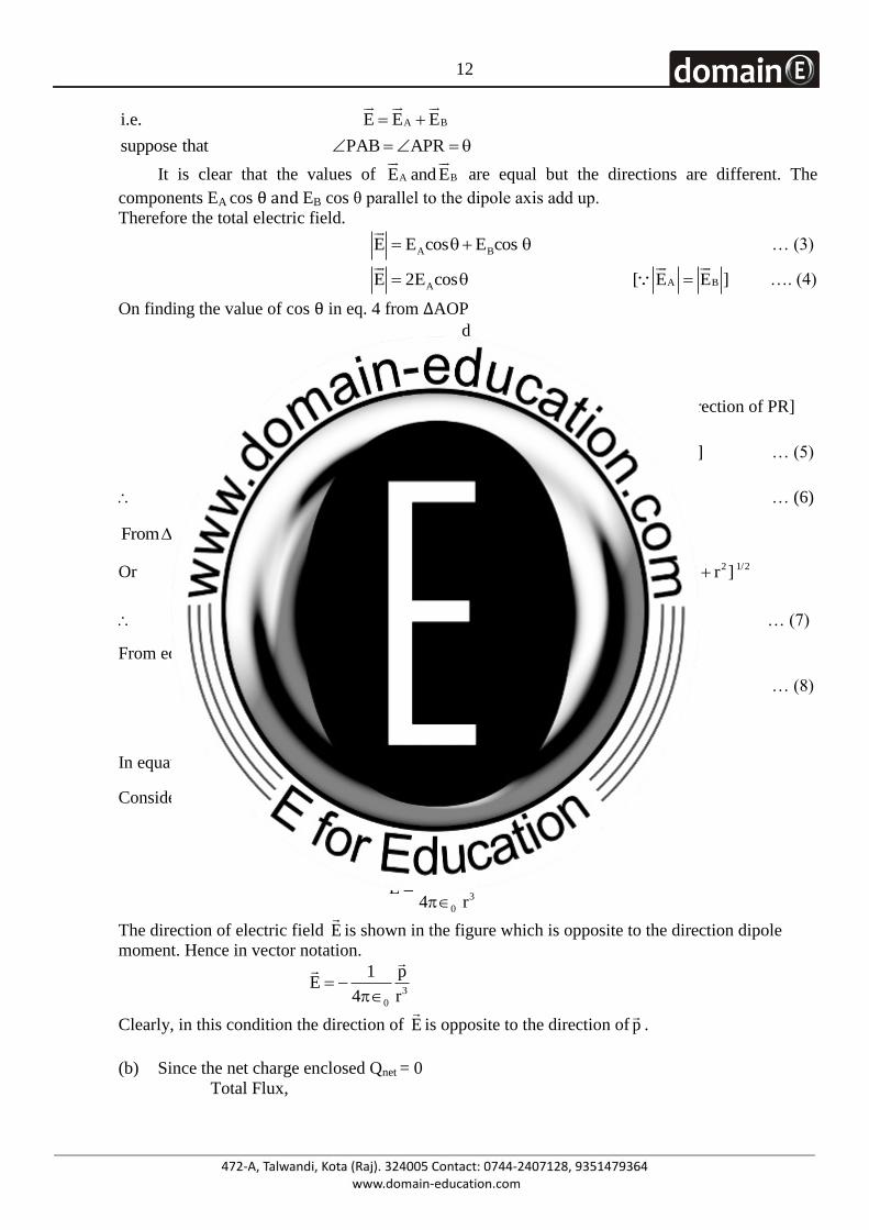
A.28 (a) Electric field due to an electric dipole at a point on the equatorial plan of the electric
dipole– As shown in figure, consider an electric dipole consisting of charges – q and + q
separated by distance d and placed in vaccum. Let P be a point on the equatorial line of the
dipole at distance r from it i.e., OP= r.
A BE and E
are electric dipole fields due to charges – q and + q respectively. Since AP = BP =
l, so magnitude of A BE and E
will be equal.
Intensity of electric field at due to the charge – q
A2
KE q
l [In the direction of PA
] … (1)
Intensity of electric field at due to b
B2
KE q
l [In the direction of PA
] … (2)
The resultant electric field E
at point P is equal to the sum of vectors A BE and E
.
12
A B
suppose that PAB AP
i.e. E E E
R
It is clear that the values of A BE and E
are equal but the directions are different. The
components EA cos θ and EB cos θ parallel to the dipole axis add up.
Therefore the total electric field.
A BE cos os E E c
… (3)
AE c sE 2 o
A B[ E E ]
…. (4)
On finding the value of cos θ in eq. 4 from ∆AOP
dOA d2cosAP 2
l l
2
K.q dE 2
2
l l [In the direction of PR]
3
Kqd
l [ p qd] … (5)
3
KpE
l … (6)
From AOP, 2 2 2AP AO OP
Or 2
2 2dr
4 l
22 1/2d
[ r ]4
l =
2
3 2 3/2d[ r ]
4 l … (7)
From equation (6) and (7)
2
2 3/2
KpE
d[ r ]
4
… (8)
In equation (8) d<<r, then
Considering 2d
4negligible in comparison to r
2
3
KpE
r
3
0
1 pE
4 r
The direction of electric field E
is shown in the figure which is opposite to the direction dipole
moment. Hence in vector notation.
3
0
1 pE
4 r
Clearly, in this condition the direction of E
is opposite to the direction of p
.
(b) Since the net charge enclosed Qnet = 0
Total Flux,
13
netE
0
E 0
Q
(c) Potential inside and on to the surface of conductor is same
V 10V .
OR (a) Capacitor− An arrangement of two conductors separated by an insulating medium is called
capacitor. It is used to store charge and electrical energy.
Equivalent capacitance in series combination−Figure shows three capacitance C1, C2 and
C3connected in series. A potential difference V is applied across the combination. This sets up
charges Q on the two plates of each capacitor.
The p.d across the various capacitors
are−
1 2 3
1 2 3
Q Q QV ,V ,V
C C C
The sum of these p.d must be equal to
the applied p.d
1 2 3
1 2 3
Q Q QV V V V
C C C
or 1 2 3
V 1 1 1
Q C C C
If Cs is the equivalent capacitance of the series combination then SCQ
V
S 1 2 3
1 1 1 1or,
C C C C
(b) Total capacitance in series combination
S
C 101 F.
n 10C
Total capacitance in parallel combination
p nC 10 1 1 0C 0 0 F
p
S p
C
C C
nC 10 10 100 F
1 100 100square F Ans.
(c) Given
r
m r
C 4 F
2
C C
2 4 8 F Ans.
14
Q.29 Write Ampere‟s circuital law.
Obtain an expression for magnetic field on the axis of current carrying very long solenoid. Draw
necessary diagram.
OR
Write the working of cyclotron in brief. Draw a schematic sketch of the cyclotron showing path of
accelerated charged particles (ions) in both Dees.
Derive the following parameters of cyclotron:
(a) Cylotron frequency and
(b) Kinetic energy of ions in cyclotron.
A.29 Ampere’s Circuital Law- “According to Ampere‟s Circuital Law the line integral of the magnetic
fie1d around any closed circuit in vacuum (or -air) is equal to the arithmetical product of
permeability constant (0 ) of vacuum and the total current passing through that closed circuit."
Therefore mathematically.
0B.d I l
Where 0 = permeability of vacuum
Solenoid- "When on a cylindrical non-conducting tube (of porcelain or card board) an insulated
copper wire is wound closely along its length in the form of a helix, then this arrangement is called
a solenoid". In the solenoid the base of every turn can be considered to be almost perpendicular to
the axis of the solenoid, the magnetic field produced is shown in the figure. Inside the solenoid
magnetic field lines are parallel and their directions are along the length of the solenoid. Therefore,
outside the solenoid the value of magnetic field is negligible.
When the length of solenoid is very large as compared to its radius r , it is considered to be a
solenoid of infinite length. Solenoid of infinite length does not have ends. Thus, inside these
solenoids magnetic field is uniform which is represented by force lines parallel to its axis. In this
condition at a point situated outside the solenoid value of magnetic field is almost zero. This is also
called ideal solenoid.
The figure shows a solenoid of length L and N number of turns. When current I is passed through
the solenoid then uniform magnetic field is obtained inside the solenoid. To determine the
intensity B of magnetic field e inside, the solenoid we consider a rectangular path PQRS.
From Ampere's law.
0PQRS
B.d I
l
15
0PQRS
Q R S P
0P Q R S
Q R S Po o o o
0P Q R S
Q
0P
Q
0P
B.d I
B.d B.d B.d B.d I
B.d cos0 B.d cos90 0 B.d cos90 I
B.d 0 0 0 I
B d I
l
l l l l
l l l
l
l
0B Il = Q
P[ d 1]l
… (1)
The number of turns in unit length of the solenoid N
Ln =
Thus, number of turns in length l of solenoid N
L= l
Total current I = no. of turns in length Il
NI I
L = l
On putting in eq. (1)
0
0
0
NB I
L
NB I .... 2
L
B nI .... 3
l = l
=
=
(Where n = N/L no. of turns in unit length)
The above equation shows the value of magnetic field produced inside the solenoid.
The direction of magnetic field in the solenoid is long its axis.
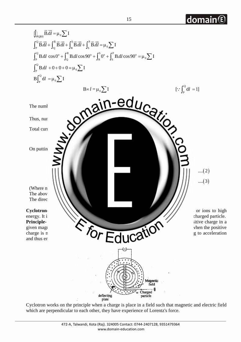
OR Cyclotron- Cyclotron is such device which is used to accelerate charged particles or ions to high
energy. It is invented by E.O. Lawrence and M.S. Livingston to obtain high energetic charged particle.
Principle- working, of cyclotron is based on its fact that periodic tie of ions and positive charge in a
given magnetic field does not depend on seep of ions and radius of circular path i. e. when the positive
charge is moving alternately in strong magnetic field of high frequency, it beginning to acceleration
and thus energy increases.
Cyclotron works on the principle when a charge is place in a field such that magnetic and electric field
which are perpendicular to each other, they have experience of Lorentz's force.
16
net
net
F F F
F E B
E B
me
q q v
q q v
Construction- It consists of two hollow D shaped metallic chambers which a source of positive
particle is kept. Dees are connected to high frequency oscillator which gives electric field of high
frequency in the interval of dees. In the arrangement magnetic field due to strong electromagnet is
perpendicular to the plane of dees.
Working – Suppose a proton injected by source at the centre of the cyclotron in figure, initially moves
towards a negatively charged dees. It will acceleration towards this dees and enter in it once inside, it
is shielded from electric field from copper walls of dees; i. e. the electric field does not enter the dees.
The magnetic field, however, is not screen by the (non-magnetic) copper dees, so the proton moves in
a circular path whose radius, which depends on its speed, is given / Br mv q . Let us assume that at
the instant, the proton enter into the center gap from the first dees, the potential difference between the
dees is reversed. Thus, the proton again faces a negatively charged dees and is again accelerated. This
process continues; The circulating proton away being in step which spiraled out to the edge of the
dees system. Then a detector plate sends it out through a portal.
Resonance Condition – The condition of working of cyclotron is that, “frequency of alternating
potential should be equal to the frequency of revolution of charged particle inside the dees. This
condition is called resonance condition".
When a proton moves perpendicular to the magnetic field in dees, applying Lorentz forces oF Bsin90 B qv qv
Where q is the charge on charged particle. This force gives centripetal forces for circular path of r
radius. (a) Frequency of cyclotron
1
Tn
2
TB
m
q
B
2
qn
m
(b) Maximum KE of positively charged particle.
2
max
max
2
maxmax
2 2 2
max
1K
2
B
B1K
2
B1
2
m
m
mv
q rv
m
q rm
m
q r
m
Here rmax = Radius of the largest half circle before coming out of D.
Q.30 Define refraction of light waves.
Draw a ray diagram for refraction at a spherical surface separating two media. For refraction at a
spherical surface derive the relation 2 1 2 1
u R
in object distance (u), image distance ( ),
refractive index of media 1 2( , ) and radius of curvature (R).
17
OR
Define interference of light waves.
Draw a diagram of Young‟s double silt experiment to produce interference fringe pattern. Derive an
expression of fringe width for bright fringes.
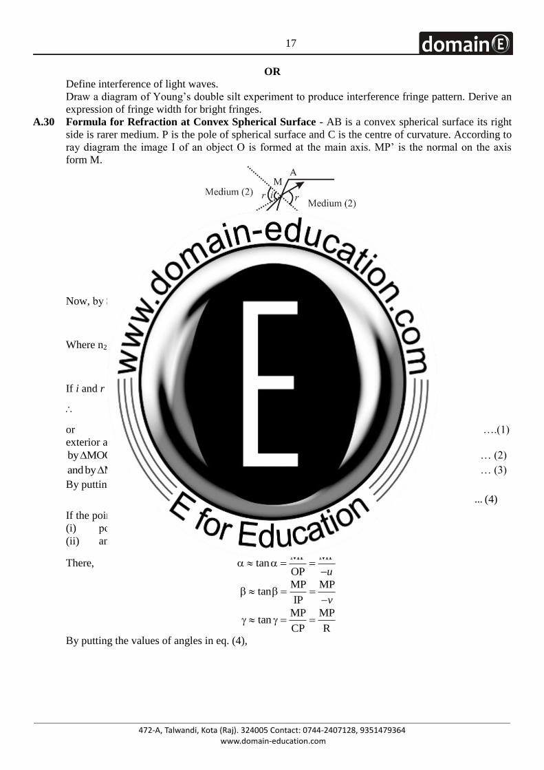
A.30 Formula for Refraction at Convex Spherical Surface - AB is a convex spherical surface its right
side is rarer medium. P is the pole of spherical surface and C is the centre of curvature. According to
ray diagram the image I of an object O is formed at the main axis. MP‟ is the normal on the axis
form M.
Now, by Snell‟s rule
21
sin in
sin r
Where n21= refractive index of second medium with respect to first medium
sin in
sin r
If i and r are smaller, sin i = i and sin r = r
i
nr
or i = nr ….(1)
exterior angle in triangle is equal to addition of interior angles of front side.
by MOC i … (2)
andby MIC r … (3)
By putting the values from eq. (2) and eq. (3) in eq. (1).
n … (4)
If the point M is not far from main axis,
(i) point P and P‟ will be coincide and
(ii) angle , and are small.
There, MP MP
tanOP u
MP MPtan
IP v
MP MPtan
CP R
By putting the values of angles in eq. (4),
18
21 21
MP MP MP MP
R R
1 1or
R R
n 1 1 1or
R R R
11or .... 5
R
nu v
n n
u v
n n
v u
n n
v u
This formula is called refraction formula for convex surface. If relative index of first and second medium are
1n and 2n .
221
1
n
nn
By equation (5)
2
2 1 2 1
1 1
11
R R
n
n n n n
n v u n
By multiplication of 1n in the equation.
2 1 2 1
R
n n n n
v u
Because R of convex surface is positive, therefore the value of u is less than
R,
1v
nwill be less
and image be formed in first medium.
Refraction
When a ray of light enters from one transparent medium into another, there is a change in speed and
direction of the ray in the second medium. This phenomenon is called retraction.
Lows of refraction: (i) The incident ray, the refracted ray and the normal to the surface separating the two media, all
lie in the same plane,
(ii) Snell's Law: For two media, the ratio of sine of angle of incidence to the sine of the angle of
refraction is constant for a beam of particular wavelength, i.e.,
where n1 and n2 are absolute refractive indices of I and II media respectively and n2, is a refractive
index of second (II) medium with respect to first (I) medium.
OR When two waves of same frequency and constant initial phase difference travel in the same direction
along a straight line simultaneously, they superpose in such a way that the intensity of the resultant
wave is maximum at certain points and minimum at certain other points. The phenomenon of
redistribution of intensity due to superposition of two wave of same frequency and constant initial
phase difference is called interference.
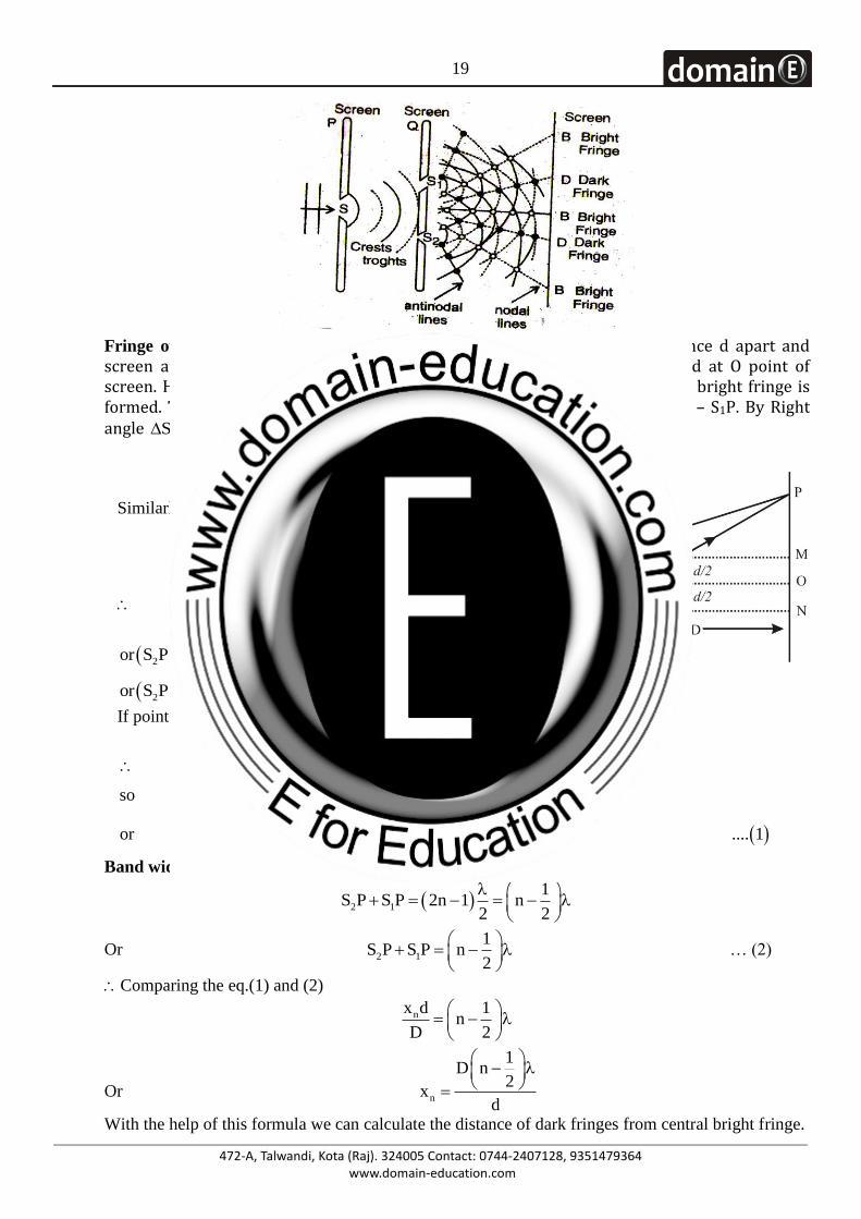
Observing Interference pattern in Young’s Double Slit Experiment−
19
Fringe of Bright Fringe−Suppose S1 and S2 are two fine slits, a small distance d apart and screen at a distance D from the slits. Perpendicular bisector lines are joined at O point of screen. Hence central bright fringe be at O. P held apart xn from O, where nth bright fringe is formed. The path difference between two waves arriving at P is equal to S2P – S1P. By Right angle 2S PN,
2
2 2 2 2
2 2S P S N PN D2
n
dx
Similarly by rightangle 1S PM,
2
2 2 2 2
1 1
2 2
2 2 2 2
2 1
S P S M PM D2
S P S P D D2 2
n
n n
dx
d dx x
2 2
2
2 1 2 1 n n n n
d dor S P S P S P S P x x d x x d
4 4
2 1 2 1 nor S P S P S P S P 2x d
If point P is not far from O, then
1 2
2 1
2 1 n
n2 1
S P S P D
S P S P D D 2D
so 2D S P S P 2x d
x dor S P S P .... 1
D
Band width of bright Fringe- if dark fringe is formed at P point, difference of path,
2 1
1S P S P 2n 1 n
2 2
Or 2 1
1S P S P n
2
… (2)
Comparing the eq.(1) and (2)
nx d 1n
D 2
Or n
1D n
2x
d
With the help of this formula we can calculate the distance of dark fringes from central bright fringe.
20
Thus,n 1
1 1D n 1 D n
2 2x
d d
Because the bright fringe be the mid of two dark fringe. Hence the width of bright fringe.
n 1 nx x
1 1D n D n
2 2
d d
D 1 1n n
d 2 2
D
d
If fringe width of bright fringes is 2mm, the fringe width of dark fringes will also be 2mm because in
interference both bright and dark fringes are of equal width.
The centre point of interference fringe pattern is bright because central point „O‟ is equidistant from
S1 and S2 producing path difference equal to zero.