XL Actuator Range Full Product Range & Technical Specifications ■ High quality and economical actuator ■ Improve plant and operator safety ■ Reliable and flexible in process control ■ Increase serviceability
Transcript
XL Actuator RangeFull Product Range & Technical Specifications
■ High quality and economical actuator
■ Improve plant and operator safety
■ Reliable and flexible in process control
■ Increase serviceability
HYTORK has been manufacturing actuators for over 30 years. Valuable input from our customers has enabled continuous improvement, resulting in our newly updated XL range of actuators.
These heavy duty actuators have a proven track record of reliable operation in both industrial and commercial applications.
The XL actuator is modular in design, allowing many different functional features to be assembled from a series of modules at the factory or on site.
All XL actuators are field convertible from double acting to spring return (or vice versa).
XL ActuatorsComplete solutions from HYTORK
XL spring return actuators are easily field modified to suit changing plant air and/or valve fail mode requirements.
Many of the XL actuators can have end cap modules added that provide a declutchable, manual override.
Hytork’s unique On-Line Test module for ESD valves can be added to all XL spring return actuators.
All XL actuators feature the new “star” pinion drive, providing greater flexibility for direct or bracket mounting to an increased range of valve designs, including valves that have an ISO 5211 design with the stem turned at 45 degrees.
All Hytork XL actuators are manufactured to the latest international interface standards: ISO 5211, NAMUR and VDI/VDE. These standards assist efficient and accurate assembly of automated packages.
The highest quality, most economical
actuator anywhere!
This unique combination of high quality, modular
actuator design, unique features,
customer benefits and economical cost has
been achieved by substantial engineering
and financial investment by HYTORK.
2
Additional Hytork XL features■ Extra mounting holes for top and bottom mounted accessories (including Hytork’s direct mount interface for butterfly valves).
■ Extra mounting holes near NAMUR solenoid valve pad to facilitate filter/regulator bracket installation.
■ Hytork’s unique direct mount interface for the most popular, non ISO 5211 designed butterfly valves.
■ Stainless steel coupling inserts for direct mount ISO 5211 valves and other popular valve stems.
■ Site proven DURASTRIP bearings protect all moving parts. Installed base has experience of actuators exceeding 1 million cycles.
■ Change a solenoid or positioner, adjust a switch, alter a spring rating or install a new set of bearings and seals (never a spring set) in just minutes.
■ A rugged, heavy duty body casting, patented SAFEKEY, unbreakable springs and HYTORK’S safety retractor rod system for disassembly of spring return actuators.
These and other Hytork features:
- reduce capital, assembly and installation costs- increase personnel and plant safety- increase plant up time- reduce maintenance costs- extend the package life
Complete Solutions with Hytork’s XLHYTORK products can be supplied to create customized packages, tailored to suit the individual customers’ needs and plant application requirements.
In addition to the many features that the XL offers, HYTORK’s Complete Solutions package can also provide the following benefits:■ Full engineering and GA drawing capability from each Valve Automation Center ■ Standard, non-standard and special application equipment.■ A guaranteed rapid response to enquiries and orders with many items stocked locally to ensure a same day service if required.■ Short lead times facilitated by a global distribution network, backed up by a stock of process control equipment.
Products
3
XL star drivepinions and adaptersAll Hytork XL pinion drives are manufactured to ISO 5211. Hytork’s “star” drive provides additional flexibility and simplicity in valve/actuator mounting. A range of pinion drive adapters allows many valves to be close mounted for a compact, low cost package.
The XL On-Line Test unitHytork’s On-Line Test module permits testing of Emergency Shut Down (ESD) and other important valves, solenoids and switches without upsetting the process.
■ Each ESD unit can have its own interlocking device to ensure only that particular tag number is tested at any one time. ■ ESD units can be retrofitted to existing HYTORK actuators and to any HYTORK automated quarter turn valve. ■ HYTORK can also provide On-Line Test units to replace any other manufacturers’ actuator and cater for individual plant requirements or special requirements for interlocking.
The XL manual overrideA simple end cap assembly exchange provides an efficient, compact, light-weight manual override for many XL models. No modification is required to valve brackets and couplings, and torque losses are eliminated. Various handwheel designs can be fitted to suit customer requirements.
The XL Commando for aggressive corrosive environmentsThe XL Commando is treated with Fluoropolymers from the Hytork CG range to give maximum protection against corrosive attack. Years of field
trials have proven this durable impregnation of all body parts (inside and out) to be the answer to many corrosive environments.
4
Features
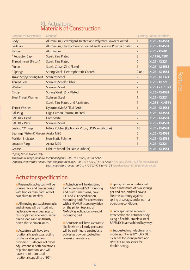
XL Actuators Materials of Construction
■ Pneumatic actuators will be double rack and pinion design with bodies manufactured of cast aluminium alloy.
■ All moving parts, piston racks and pinions will be fitted with replaceable wear bearings to resist cylinder side loads, radial pinion loads and up thrust/ down thrust pinion loads.
■ Actuators will have two rotational travel stops, acting on the rotating pinion, providing 10 degrees of travel adjustment in both directions of pinion rotation, and will have a minimum total rotational capability of 96°.
■ Actuators will be designed to the preferred ISO mounting and drive dimensions, have ISO and VDI specification mounting pads for accessories with a NAMUR accessory drive on the pinion top and a NAMUR specfication solenoid mounting pad.
■ Actuators will have a ceramic like finish on all body parts and will be cerimigard treated and polyester powder coated for corrosion resistance.
■ Spring return actuators will have a maximum of two springs per end cap, and will have a lifetime warranty against spring breakage, under normal operating conditions.
■ End caps will be securely attached to the actuator body using a flexible, stainless steel SAFEKEY in a machined key way.
■ Suggested manufacturer and model number is HYTORK XL SR series for spring return and HYTORK XL DA series for double acting.
Actuator specification
5
Component Description Material Quantity Model Numbers
Body Aluminium, Ceramigard Treated and Polyester Powder Coated 1 XL26 - XL4581
End Cap Aluminium, Electrophoretic Coated and Polyester Powder Coated 2 XL26 - XL4581
Position Indicator Non-Static Polymer 1 XL26 - XL4581
Location Ring Acetal M90 1 XL26 - XL221
Grease Lithium based (for Nitrile Rubber) XL26 - XL4581
*Spring Return Models Only Temperature range for above mentioned parts: -20°C to +100°C/-4°F to +212°FOptional temperature ranges: High temperature range : -20°C to +120°C/-4°F to +248°F (see data sheet D128 for more details) Low temperature range: -40°C to +100°C/-40°F to +212°F (see data sheet D129 for more details)
Rugged heavy duty construction
NAMUR solenoid mounting pad
Large internal air passages
ISO 5211 valve mounting pad plus additional holes for close mounting
Safekey system
LIFETIME guarantee on springs
Cast in identification on body
Large rack and pinion
VDI/VDE 3845 NAMUR accessory mounting
Pinion seals
Bi-directional Travel Stops
Corrosion resistant Cobalt Zinc plated pinion
Versatile modular design
Added standard corrosion protection
“CERAMIGARD”
DURASTRIP bearings
Simple, no frills concept
102
1
11Star drive pinion
17
3
8
9
6 18 155137
16144
Safekey systemThis patented Safekey method of end cap assembly to the actuator uses a flexible stainless steel key in an internal machined keyway. The Safekey is completely sealed from all external contamination. Stronger than conventional bolting, more secure than Helicoils™, the Safekey system eliminates stress concentrations caused by point loading. Safekeys cannot be removed when the XL actuator is pressurized or springs are not safely contained, eliminating potentially dangerous disassembly.
1 DURASTRIP bearingsAll moving parts are protected by permanently lubricated, long lasting DURASTRIP bearings that extend the actuator’s life in the most severe and demanding conditions.
Large internal air passagesHYTORK’s extra large internal air passages permit maximum speed of operation and greatly reduce the possibility of the air passages blocking.
VDI/VDE 3845 NAMUR accessory mounting(an international standard)This standard includes a slotted drive in the top of the pinion, providing a self centering, positive, no play drive for top mounted accessories. All switches, positioners, etc. manufactured to the VDI/VDE standard, can be directly driven by the actuator pinion, eliminating expensive couplings. Hytork’s standard visual position
2
3
4
XL Actuator
12
6
10
11
9
8
5
6
7
indicator, snaps on to this pinion design. This “standard” mounting pad simplifies the addition of all “state-of-the-art” top mounted accessories. Using HYTORK’s engineered “SAFEMOUNT” bracketing, ANY accessory made to the VDI/VDE standard can be mounted to the actuator or one can still connect a remote mounted solenoid. The choice is yours. Versatile modular designCustomize the Hytork actuator to fit your needs. Hytork’s modular design permits shop or field changes in action (double acting or spring return), fail position, spring rating, manual override requirements, plus testing and locking devices.
Pinion sealsPinion seals are positioned as close to the external surfaces as possible to minimise any crevices for maximum protection against corrosion.
NAMUR solenoid mounting pad (an international standard)This permits a choice of various manufacturers’ solenoid valves to be direct mounted to the actuator. A single solenoid can be used for all double acting and spring return sizes. Hytork’s “CATS” direct mounted solenoid valve prevents aggressive ambient air from entering the spring chambers. In addition to the NAMUR holes many sizes of the XL actuator range are also provided with four additional holes to assist attaching brackets for filter regulators and solenoid valves that cannot be direct mounted.
LIFETIME guarantee on springsPut the SAFE in Fail Safe! HYTORK’s springs are designed and manufactured never to break, and are then protected from corrosion using an electro-phoretic finish. Springs are rated to compensate for “spring set” for true fail safe confidence. Hytork springs are guaranteed for life under normal operating conditions and backed by a FREE complete actuator replacement. Hytork springs can be matched for any air supply pressure and valve requirement - easily and safely.
“CERAMIGARD”The body has a unique surface finish of Di-aluminium Tri-oxide (Al2O3); a hard, corrosion resistant ceramic like surface, protecting all body parts against wear and corrosion.
Simple, no frills conceptOnly three moving parts; one pinion, two pistons.
ISO 5211 valve mounting pad (an international standard) plus additional holes for close mountingHytork XL actuators are all provided with ISO 5211 mounting holes. Many sizes have two ISO 5211 hole patterns plus additional holes outside the ISO pattern. These two hole patterns provide flexibility in mounting to all types and makes of quarter turn valves, whether they are ISO 5211 or not. The outer mounting holes, coupled with HYTORK’s optional, low cost mounting subplates, allow the close coupling of most makes of valves that are not ISO 5211.
Features
7
Rugged heavy duty constructionThe XL body is designed and built from a heavy duty aluminium casting to provide maximum protection against dents, shock or fatigue.
Large rack and pinion for precision modulating control applicationsThe extra large, precision rack and pinion reduces “dead band” for accurate modulating control applications.
Cast in identificationModel numbers, port identifications and safety instructions are cast in for permanent readability. No lost identification due to weathering or paint.
Added standard corrosion protectionA polyester powder coated surface treatment is standard, providing extra protection against aggressive environments.
Excellent overall corrosion resistanceAll Hytork actuator pinions are Cobalt Zinc plated. This durable pinion treatment together with our ‘ceramigard’ surface finish and standard powder coated paint shows no decline of actuator functions after 1000 hours salt spray test.
Star drive pinions andnew stainless steel adaptersAll Hytork XL pinion drives aremanufactured to ISO 5211.Hytork’s new star drive providesadditional flexibility and simplicity in valve/actuator mounting. Optional star drive sizes are available. A rangeof pinion drive adapters allows many valves to be close mounted for a compact, low cost package.
12
13
14
15
16
17
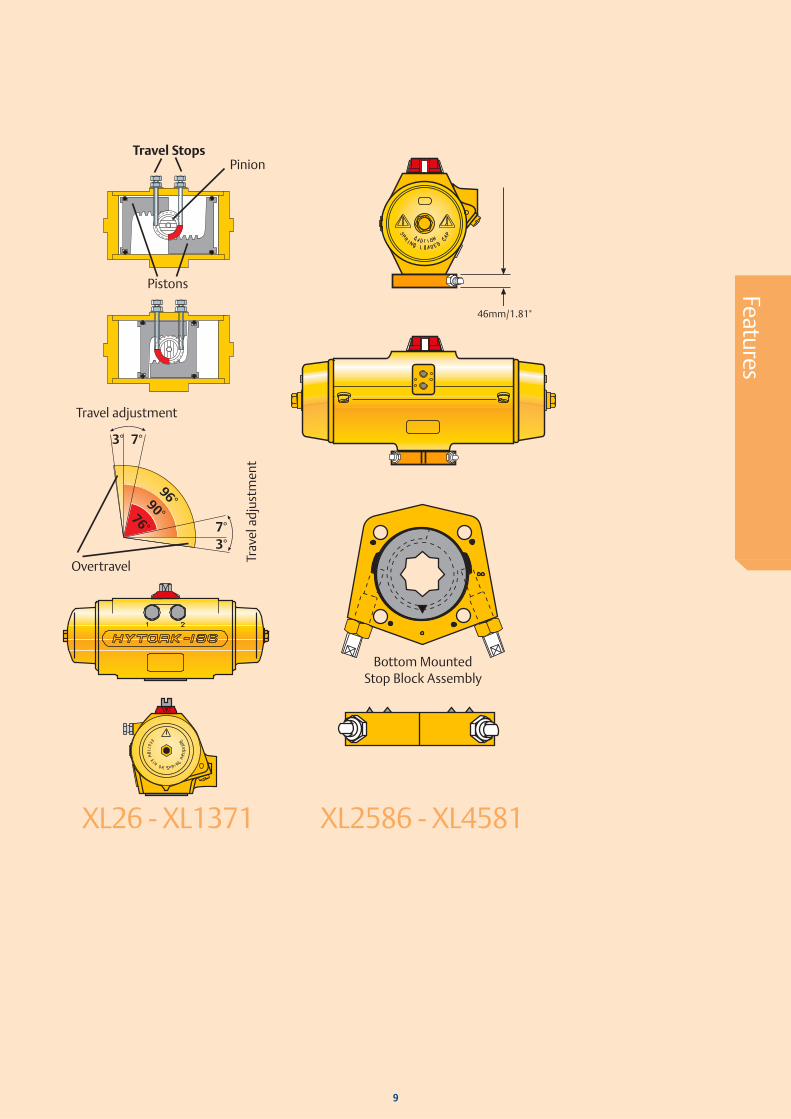
Bi-directional Travel Stops
XL26 - XL13711 A unique, exclusive standard provides rotational adjustment on the actuator pinion, in both directions of travel. 2 High performance and special duty valves require precise and specific rotation limits to perform their intended function. 3 Metal seated and high performance butterfly valves need exact rotation stopping between 0° and 7°. 4 Rubber seated butterfly valves often require stopping between 0° and 7° after installation, for optimum seat life. These valves can experience premature seat failure if the disc is forced into the seat. 5 Full port and metal seated ball valves need exactly 0° and 90°. 6 All manufactured items have acceptable tolerances. When the tolerance of the components of an automated valve assembly are added, the actuator must provide compensation by being able to rotate more than 90° with overtravel in both directions, and then continually stop precisely at the required position. 7 Hytork actuators, with patented two way rotation travel stops, provide a minimum rotation of -3° to +93° and positive, adjustable rotation stopping (10° at each end).
18 Valve OpenNo Travel Stops
Valve ClosedNo Travel Stops
Valve Openwith Travel Stops
Ball Plug
Ball Plug
Lost through put
100% through put
Possibleangularmisalignment
Possibleangularmisalignment
Possibleangularmisalignment
Valve leaksBall is damagedSeats erode
8 This unique Hytork combination assures positive sealing, correct port alignment and long life for all valve designs. 9 Single end cap stops and dual end cap stops cannot limit rotation when the actuator pistons are driven together (as in all “fail” strokes) and provide no function. Actuators without sufficient overtravel, in both directions of rotation, cannot assure correct valve functioning.10 Overtravel and Rotation Travel Stops are required to compensate for the accumulation of tolerances that lead to valve malfunction and damage.
XL2586 - XL4581On the larger sizes of Actuators the adjustment is obtained by the addition of a simple Stop Block that fits under the Actuator. The Actuator is manufactured with over travel to give -3° to +93° of movement and the bottom mounted Stop Block provides the required adjustment of 10° at each end of the travel.
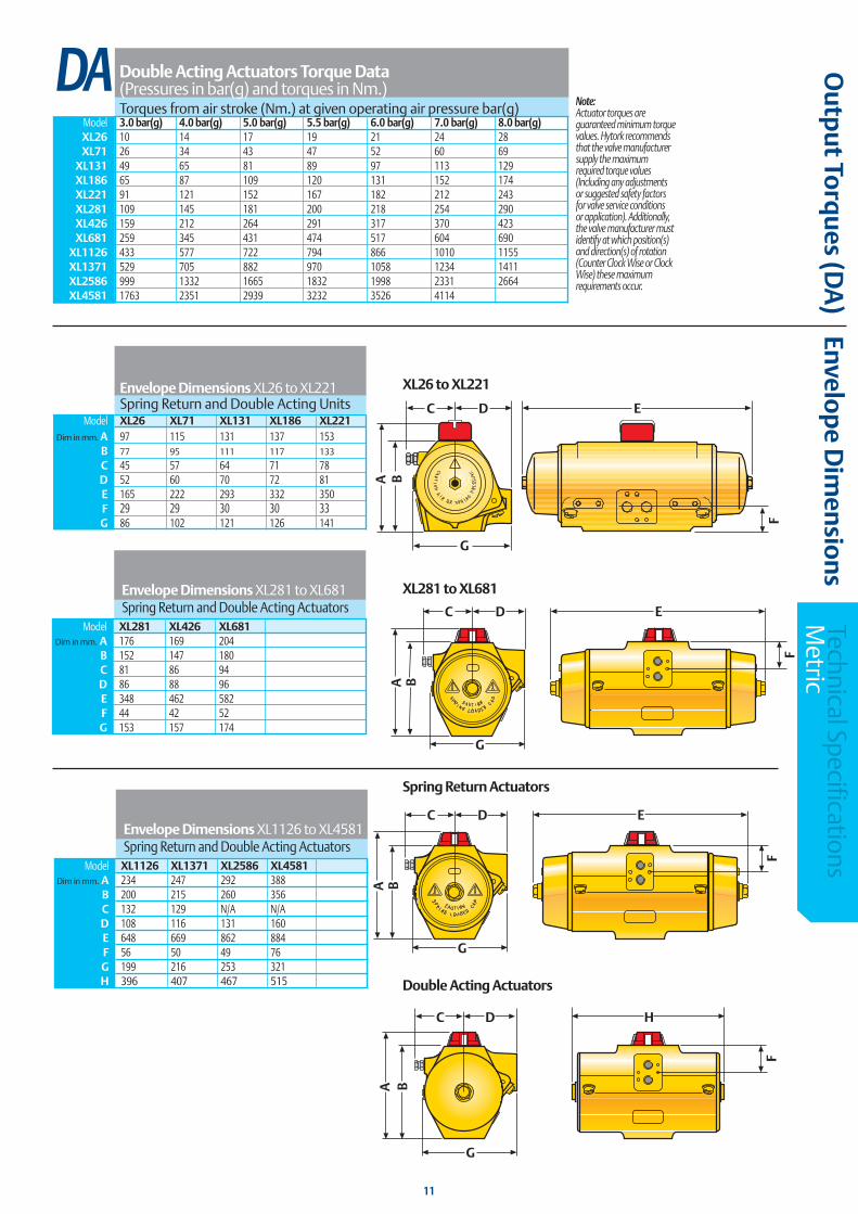
Note:Actuator torques are guaranteed minimum torque values. Hytork recommends that the valve manufacturer supply the maximum required torque values (Including any adjustments or suggested safety factors for valve service conditions or application). Additionally, the valve manufacturer must identify at which position(s) and direction(s) of rotation (Counter Clock Wise or Clock Wise) these maximum requirements occur.
Maximum working pressure:Models XL 26 - 2856 8 bar(g) XL 4581 7 bar(g)
Hytork XL Spring return actuators can be equipped with the additional spring sets S50, S70 and S90 for more accurate sizing. Please download data sheet D66 from www.Hytork.com for the torque data, belonging to these additional spring sets.
S1C Spring ReturnFor all fail closed butterfly valves and other spring return applications where 7 bar air is available, Hytork's optional S1C Spring Modules will often permit the selection of a smaller Hytork Actuator. Both space and cost savings can be achieved.
Note:Actuator torques are guaranteed minimum torque values. Hytork recommends that the valve manufacturer supply the maximum required torque values (Including any adjustments or suggested safety factors for valve service conditions or application). Additionally, the valve manufacturer must identify at which position(s) and direction(s) of rotation (Counter Clock Wise or Clock Wise) these maximum requirements occur.
Ou
tput Torq
ues (DA
)Envelop
e Dim
ensionsTechnical Specifications M
etric
Envelope Dimensions XL26 to XL221 Spring Return and Double Acting Units Model XL26 XL71 XL131 XL186 XL221 Dim in mm. A 97 115 131 137 153 B 77 95 111 117 133
C 45 57 64 71 78 D 52 60 70 72 81 E 165 222 293 332 350 F 29 29 30 30 33 G 86 102 121 126 141
ED
BA
C
G
F
D
F
HC
G
BA
Model XL281 XL426 XL681 Dim in mm. A 176 169 204 B 152 147 180 C 81 86 94 D 86 88 96 E 348 462 582 F 44 42 52 G 153 157 174
Envelope Dimensions XL281 to XL681Spring Return and Double Acting Actuators
DA
ED
BA
C
G
F
Model XL1126 XL1371 XL2586 XL4581 Dim in mm. A 234 247 292 388 B 200 215 260 356 C 132 129 N/A N/A D 108 116 131 160 E 648 669 862 884 F 56 50 49 76 G 199 216 253 321 H 396 407 467 515
Envelope Dimensions XL1126 to XL4581Spring Return and Double Acting Actuators
11
XL26 to XL221
Spring Return Actuators
XL281 to XL681
Double Acting Actuators
ØK
H
ØJ
F squareG
4 holes A x B deep
on C PCD
4 holes D x E deep
Centring ring
L
Val
ve/D
amp
er M
ount
ing
Det
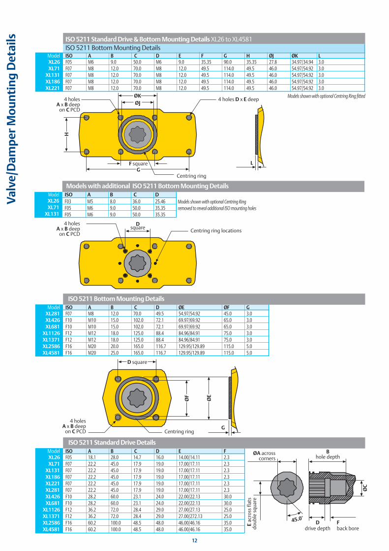
ails ISO 5211 Standard Drive & Bottom Mounting Details XL26 to XL4581
ISO 5211 Bottom Mounting Details Model ISO A B C D E F G H ØJ ØK L XL26 F05 M6 9.0 50.0 M6 9.0 35.35 90.0 35.35 27.8 34.97/34.94 3.0 XL71 F07 M8 12.0 70.0 M8 12.0 49.5 114.0 49.5 46.0 54.97/54.92 3.0 XL131 F07 M8 12.0 70.0 M8 12.0 49.5 114.0 49.5 46.0 54.97/54.92 3.0 XL186 F07 M8 12.0 70.0 M8 12.0 49.5 114.0 49.5 46.0 54.97/54.92 3.0 XL221 F07 M8 12.0 70.0 M8 12.0 49.5 114.0 49.5 46.0 54.97/54.92 3.0
Models shown with optional Centring Ring fitted
Dsquare
4 holes A x B deep
on C PCDCentring ring locations
Models with additional ISO 5211 Bottom Mounting Details Model ISO A B C D XL26 F03 M5 8.0 36.0 25.46 XL71 F05 M6 9.0 50.0 35.35 XL131 F05 M6 9.0 50.0 35.35
Models shown with optional Centring Ringremoved to reveal additional ISO mounting holes
ISO 5211 Bottom Mounting Details Model ISO A B C D ØE ØF G XL281 F07 M8 12.0 70.0 49.5 54.97/54.92 45.0 3.0 XL426 F10 M10 15.0 102.0 72.1 69.97/69.92 65.0 3.0 XL681 F10 M10 15.0 102.0 72.1 69.97/69.92 65.0 3.0 XL1126 F12 M12 18.0 125.0 88.4 84.96/84.91 75.0 3.0 XL1371 F12 M12 18.0 125.0 88.4 84.96/84.91 75.0 3.0 XL2586 F16 M20 20.0 165.0 116.7 129.95/129.89 115.0 5.0 XL4581 F16 M20 25.0 165.0 116.7 129.95/129.89 115.0 5.0
Hytork also manufacture a range of accessories including VDI/VDE engineered accessory mounting kits, switches, solenoid valves, positioners and manual override gearboxes to fit all Hytork actuators.
The XL Series of rack and pinion actuators has twelve (12) sizes in Double acting and Spring return versions with torque outputs up to 35,000 inch.lbs Double acting.
SAFEMOUNT Mounting kits for all types and makes of quarter turn valves are also designed and manufactured by HYTORK.
HYTORK products and servicesIn addition to the XL actuator range Hytork can also offer valve sizing, valve package assembly and engineered solutions to suit all your quarter turn valve automation requirements, available at our Valve Automation Centers.
For details on any of these products and other services please contact HYTORK or your local distributor, or visit our website.