X.L. BAND W/ SPRING ASSIST INSTRUCTION MANUAL PARTS LIST (2) Bands (1) Handle assembly (2) Side hinge assemblies (1) Left rear hinge assembly (1) Right rear hinge assembly (2) front spring brackets (2) rear spring brackets (2) springs (4) black vinyl caps (1) Hardware bag: (14) ¼” –20 x 5/8” clinch studs (4) ¼”-20 x 3/4” clinch studs (18) ¼”-20 keps nuts (2) ¼”-20 x ½” clinch studs (2) ¼”-20 acorn nuts (2) 5/16”-18 x 2” carriage bolts (2) 5/16” flat washers (2) 5/16”-18 hex nuts 1 tape measure or ruler. anual are as viewed from the (optional nest or table) on a flat & level surface. Carefully remove all the e to the handle OTE: If you is TOOLS REQUIRED 7/16” wrench, ½” wrench, Note: All references to Left & Right in this m front (facing the vent / draft door) of the Egg. STEP 1: Place the egg stand of your choosing internal components from inside the egg bottom. (Save the foam / cardboard pads that separated the egg bottom from the dome during shipping, these will be useful in step 4) With the aid of an assistant, place the egg bottom into the stand with th lower vent door facing forward. Carefully replace all the internal components back into the egg bottom. STEP 2: Open the hardware bag and locate the (2) ¼”-20 x ½” clinch studs (shortest two), insert them in attachment holes in the upper band, then install & hand tighten the (2) ¼”-20 acorn nuts (Illustration A) (NOTE: both bands are identical and some holes are not used, they become upper & lower bands after the hardware is installed as specified). Install (4) ¼”-20 x 3/4” clinch studs (longest 4) into the lower band as illustrated with ¼”-20 keps nuts hand tightened to hold them in place. Install (12) ¼”-20 x 5/8” clinch studs into the remaining positions as illustrated (Illustration A). N are installing the optional Egg-Mate tables at this time, you will want to insert the (4) ¼”-20 x 5/8” clinch studs (provided with the Egg-mates) into the lower band only (step 1 of the Egg- Mate manual). Some of the illustrations in th manual show the optional egg-mate clinch studs in place.
Transcript
X.L. BAND W/ SPRING ASSIST INSTRUCTION MANUAL
PARTS LIST
(2) Bands (1) Handle assembly (2) Side hinge assemblies (1) Left rear hinge assembly (1) Right rear hinge assembly (2) front spring brackets (2) rear spring brackets (2) springs (4) black vinyl caps (1) Hardware bag: (14) ¼” –20 x 5/8” clinch studs (4) ¼”-20 x 3/4” clinch studs (18) ¼”-20 keps nuts (2) ¼”-20 x ½” clinch studs (2) ¼”-20 acorn nuts (2) 5/16”-18 x 2” carriage bolts (2) 5/16” flat washers (2) 5/16”-18 hex nuts
1
tape measure or ruler.
anual are as viewed from the
(optional nest or table) on a flat & level surface. Carefully remove all the
e
to the handle
OTE: If you
is
TOOLS REQUIRED 7/16” wrench, ½” wrench, Note: All references to Left & Right in this mfront (facing the vent / draft door) of the Egg. STEP 1: Place the egg stand of your choosinginternal components from inside the egg bottom. (Save the foam / cardboard pads that separated the egg bottom from the dome during shipping, these will be useful in step 4) With the aid of an assistant, place the egg bottom into the stand with thlower vent door facing forward. Carefully replace all the internal components back into the egg bottom.
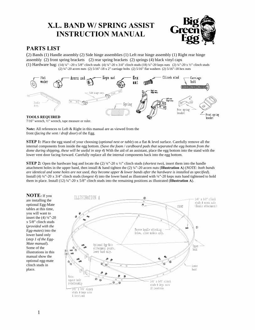
STEP 2: Open the hardware bag and locate the (2) ¼”-20 x ½” clinch studs (shortest two), insert them inattachment holes in the upper band, then install & hand tighten the (2) ¼”-20 acorn nuts (Illustration A) (NOTE: both bands are identical and some holes are not used, they become upper & lower bands after the hardware is installed as specified). Install (4) ¼”-20 x 3/4” clinch studs (longest 4) into the lower band as illustrated with ¼”-20 keps nuts hand tightened to hold them in place. Install (12) ¼”-20 x 5/8” clinch studs into the remaining positions as illustrated (Illustration A). Nare installing the optional Egg-Matetables at this time, you will want to insert the (4) ¼”-20x 5/8” clinch studs (provided with the Egg-mates) into thelower band only (step 1 of the Egg-Mate manual). Some of the illustrations in thmanual show the optional egg-mate clinch studs in place.
STEP 3: Install the lower band onto the egg bottom; the square hole in the flange at the end of the band should be to the left
es.
-inch
ement and
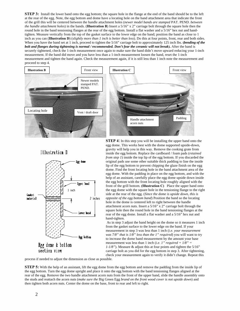
at the rear of the egg. Note, the egg bottom and dome have a locating hole on the band attachment area that indicate the front of the grill this will be centered between the handle attachment holes (newer model bands are stamped PAT. PEND. between the handle attachment holes) in the bands. (Illustration B) Insert a 5/16” x 2” carriage bolt through the square hole then the round hole in the band tensioning flanges at the rear of the egg bottom. Install a flat washer and a 5/16” hex nut and hand-tighten. Measure vertically from the top of the gasket surface to the lower edge on the band; position the band as close to 1inch as you can (Illustration D) (slightly more than 1 inch is better than less). Do this at four points, front, rear and both sidWhen you have the band set at 1 inch, proceed to tighten the 5/16” carriage bolt to approximately 125 inch lbs. (bending of the bolt and flanges during tightening is normal / recommended. Don’t fear the ceramic will not break). After the band is securely tightened, check the 1-inch measurement once again to make sure the band didn’t move upward reducing your 1measurement. If the band did move and you have less than a 1-inch measurement loosen the band, reset the 1-inch measurement and tighten the band again. Check the measurement again, if it is still less than 1 inch note the measurproceed to step 4.
2
STEP 4: In this step you will be installing the upper band onto the
h the
just the band height on the dome so it measures 1 inch
ent
16” g,
process if needed to adjust the dimension as close as pos STEP 5: With the help of an assistant, lift the egg dome from the egg bottom and remove the padding from the inside lip of the egg bottom. Turn the egg dome upright and place it onto the egg bottom with the band tensioning flanges aligned at the rear of the egg. Remove the two handle attachment acorn nuts from the front of the upper band, slide the handle assembly onto the studs and reattach the acorn nuts (make sure the Big Green Egg brand on the front wood cover is not upside down) and then tighten both acorn nuts. Center the dome on the base, front to rear and left to right.
egg dome. This works best with the dome supported upside-down, gravity will help you in this way. Remove the cooking grate from inside the egg bottom. Replace the cardboard / foam pads (retainedfrom step 1) inside the top lip of the egg bottom. If you discarded theoriginal pads use some other suitable thick padding to line the inside lip of the egg bottom to prevent chipping the glaze finish on the egg dome. Find the front locating hole in the band attachment area of the egg dome. With the padding in place on the egg bottom, and with the help of an assistant, carefully place the egg dome upside down inside the egg bottom with the front locating hole roughly aligned with the front of the grill bottom. (Illustration C) Place the upper band onto the egg dome with the square hole in the tensioning flange to the right side at the rear of the egg. (Since the dome is upside down, this is opposite of the egg bottom band) Position the band so the locating hole in the dome is centered left to right between the handle attachment acorn nuts. Insert a 5/16” x 2” carriage bolt througsquare hole then the round hole in the band tensioning flanges at the rear of the egg dome. Install a flat washer and a 5/16” hex nut and hand-tighten. As in step 3 adfrom the gasket surface to the lower edge on the band. If your measurement in step 3 was less than 1 inch (i.e. your measuremwas 7/8” that is 1/8” less than the 1” required) you will want to try to increase the dome band measurement by the amount your base measurement was less than 1 inch (i.e. 1” required + 1/8” = 1-1/8”). Measure & adjust this at four points and tighten the 5/carriage bolt as you did for the egg bottom in step 3. After tightenincheck your measurement again to verify it didn’t change. Repeat this
sible.
Locating hole
Illustration CFront view Front view Illustration B
Newer models stamped PAT. PEND.
Vent / draft door
Padding Handle attachment acorn nuts
3
Illustration FRear view Illustration E
Inside Outside Upper hinge bracket slot
STEP 6: Remove the 8 nuts from the clinch studs for rear hinge top edge of the upper band to the bottom edge of the lower band (at two places, just outside of where the rear hinge brackets will attach (a small vertical slot for fine adjustment as needed. If your measurement was 2” + - 1/16” as specified in (and position it so the top edge of the lower hinge bracket is flusthe nuts and tighten the inside nut first, then the outside nut,
bracket attachment. Measure the vertical distance from the It should be 2” plus or minus 1/16”). Make this measurement
Illustrations D & E). The rear lower hinge bracket has
Illustration D), place the hinge assembly onto the studs in both bands h / even & parallel with the top edge of the lower band. Install
make sure the bracket doesn’t move during tightening. Repeat this procedure for the opposite rear hinge assembly.
f your measurement was less than the specified 2” distance by more than 1/16” position the lower bracket downward as far as
the closed / boxed end of your ½” wrench onto the
g bottom from moving. Firmly grasp the
¼”). The goal is to create a small gap (1/16” to 1/8”)
t
k
STEP 8A: Remove the 8 nuts that will attach the left & right side hinghinge bracket onto the studs in the lower band. Position a rear spring brathe nuts. Attach a slotted front spring bracket to the inside of the side linround hole in the spring bracket then through the round hole in the side spring bracket should overhang the edge of the side link bar facing the fformed to prevent it from rotating on the link bar. (Illustration H) Rotate the side link bar forward into position so the upper side hinge bracket can be placed onto the studs in the upper band. Instalthe opposite side hinge assembly. After both assemblies are in place, look at the outer slot and the stud in the upper side hin
racket. (Illustration I) You need to have slot space available to allow the dome to be moved forward as needed. If you DO
t /
Ipossible on the clinch studs. Install the nuts and tighten the inside nut first, then the outside nut, make sure the bracket doesn’tmove during tightening. Repeat this procedure for the opposite rear hinge assembly. Look at the location of the clinch studs in relationship to the slot in the upper hinge bracket; (Illustration F) you may have to slightly rotate the dome to equalize the location of the studs in the left & right brackets. Install the nuts for the upper hinge brackets and securely tighten, starting with the inside nut first.
STEP 7: Make sure the dome is still centered left to right on the egg bottom. At the rear of the egg, place
band tensioning carriage bolt of the upper / dome band. Brace your knee against the egg bottom to prevent the egwrench and use it as a handle to gently pull the egg dome rearward (Illustration G) (typically 1/8” to
between the dome and base gaskets at the rear of the egg. Remove your ½” wrench and proceed to the fronof the egg. Grasp the dome lift handle and slowly lift straight up, do not pull forward, between ½ inch and no more than 1 inch, then lower the dome bacdown. (This allows the dome to rotate forward on the hinge to the proper location on the bottom) If you lifted the dome too far repeat step 7. Once step 7 is complete Do Not move the dome until instructed in step 9.
e assemblies, 4 from each band. Position the lower side cket onto the same studs install and securely tighten k bar using a ¼”-20 x5/8” clinch stud through the link bar and install a ¼” nut. The slotted section of the ront of the egg. The front spring bracket is offset
l and hand tighten the inner nut only. Repeat this for ge
bNOT have the slot space required proceed to STEP 8B. If you DO have the required slot space on both sides, install the outer nuts and tighten the upper front hinge brackets (inner nut first) at this time also tighten the front spring bracket nuts and proceed to Step 9. Step 8B: On the rare occasion that you don’t have slot space in front of the studs, this could be caused by a combination of two things. 1: The dome is somewhat larger in circumference than the bottom of the egg. Since the metal bands are die cupunched simultaneously they are very accurate and can be considered as a tape measure. Simply look at the gap at the
Measure here
Lower hinge bracket, top edge
Illustration G ½” wrench
Warning tag
tensioning flanges at the rear of the egg, if the dome band has a larger gap between the tensioning flanges than the bottom band the dome is larger in circumference. 2: The egg dome or the bottom could be out of round. Re-adjusting the bands can usually compensate for these conditions. By raising the upper band or lowering the lower band or lowering the lower rear hinge bracket causes the dom
4
e to have to be moved rearward. (For every 1/16” that you move either band the dome will then
nd
nsioning bolt and re-position the band as needed. Remember don’t rotate the band; only slide it up or down as needed. If the ands are at the upper or lower limits then you have the small vertical slot in the lower rear hinge bracket that you can adjust
en closing that could catch you off guard. We recommend you use both hands until you get comfortable ening and closing cycles.
tep 10. If the problem persists contact your Big Green Egg dealer for assistance.
need to be moved rearward by 1/8”). First remove the upper side hinge brackets from the studs in the upper bands and swing the side link bars down out of the way. If you have room to move the upper band upward further or the lower band downwardfurther please do so accordingly. Completely loosen all 8 of the rear hinge bracket to band attaching nuts and then the batebdownward. Re tighten all 4 of the lower rear hinge bracket nuts first then the upper 4 nuts. Now return to step 7 and continuefrom there. Step 9: With the hinge attaching hardware properly tightened, you need to check the bottom to dome gasket seal. You do thisby fully opening the dome (read CAUTION below) and placing a dollar bill centered lengthwise across the bottom gasket then close the dome on it. Now slowly pull the dollar bill out and you should feel some resistance, this indicates the gaskets aremaking good contact. The slightest resistance will provide a good seal especially after the gaskets compress after use. You should perform this test at 4 points front, rear and both sides. When you have a good seal at all four points proceed to step 10. Caution: The dome is heavy and difficult to open until the assist springs are installed; it also has a rapid weight transfer whwith the op On the rare occasion that the gasket seal test would fail, take note of the area that isn’t sealing properly. If the area is at the rear of the egg, inspect the rear hinge assemblies to make sure nothing is binding or that the upper hinge bracket isn’t contacting the lower bracket thereby holding the dome up. Open the dome fully and inspect both gasket surfaces for foreignmaterial or irregularities that may prevent the dome from sealing. Perform the seal test again if you have a good seal proceed to s
Illustration H Illustration I Left side viewLeft, rear view
Front spring bracket
Front
Slot space in front of the studs
Illustration J Illustration KLeft, rear / front view Left side view
Front spring bracket
Rear spring bracket
Left side hinge adjustment, move the dome to the right. Right side hinge adjustment, move the dome to the left.
Upper side hinge bracket
Side link bar
5
Step 10: Fully open the egg dome. Insert one hook end on the sp ng downward through the round hole in the rear spring bracket, then the opposite hook end downward through the slottedhanging in place and your assembly should look like (Illustrationcarefully close the dome. Open and close the dome several times in place. Perform the gasket seal test once again the same as you did It’s not uncommon for the gasket seal test to fail at the rear of theto travel slightly more forward. Fully open the dome and remove e springs installed). Then carefully close the dome (Remember it wnuts on the upper side hinge bracket on the left side of the egg onl side hinge bracket along the back edge of one of the nuts to mark block the casters so the nest won’t move. Stand to the left of the l e lift handle and gently slide / push the dome to the right side of the egg as you washould move forward in the slotted hinge bracket as you move the d in the slots from there original location. Tighten both nuts securel
n
ri hole in the front spring bracket. The spring should be J). Repeat this for the opposite side of the egg. Now
to familiarize yourself, this also allows the parts to seat earlier. egg this is easily remedied. The dome needs to be allowed both springs (never attempt to make this adjustment with thill be heavy without the springs). Completely loosen both y. Put a piece of tape or make a pencil mark on the upperthe current position in the slot. If you are using an egg nest ift h t of the egg. Grasp thandle at the fron
the studtch s in the upper side hinge bracket. The studs dome. (Illustration K) Move the studs about 1/8” forwary and repeat this process on the right side of the egg.
Remember, you will move the dome to the left when adjusting the right side hinge bracket. After you complete the right side adjustment, you can open the dome and re-install both springs as you did earlier. When both springs are in place you can opeand close the dome several times and then repeat the gasket seal test. If the gaskets are still loose at the rear, remove the springs and repeat this process to move the dome further forward in the upper side hinge brackets. Install the black vinyl protective caps onto the ends of the spring hooks and you are done (Illustration L).
Illustration L
Front spring bracket Spring
Rear spring bracket
Congratulations, you have completed the hinge / band installation. Periodically lubricate the (8) pivot points on the hinge mechanism with light oil (penetrating lubricants such as WD 40 are not recommended) and it will provide you many years of trouble free service. Thank you for your purchase; this product was designed & manufactured in the U.S.A. exclusively for Big Green Egg.
Vinyl protective caps
6
PORTANT: You must check the band bolts and the hinge / band bolts for tightness regularly, especially after each of e first two or three uses. Failure to follow these instructions may cause the dome to slip out and break; this will not be vered under warranty. (NEVER TIGHTEN THE BANDS WHEN THE GRILL IS IN USE)
aution: Extension springs are a source of energy and should be removed before making any djustments to your hinge / band assembly or personal injury could occur.
r hinge mechanism. ▲ Do not move the egg over rough or uneven surfaces, or by pulling the handle.
ctioning. ot place hands / fingers in or near the hinge mechanism, many pinch points exist.
perate the egg.
LBW/SA 8-24-07
IMthco Ca SAFETY WARNINGS
▲ Do not lift or transport the egg assembly by grasping the handle o
▲ Do not place your hands inside the egg until the lid is completely open. ▲ Periodically lubricate the hinge mechanism to insure proper fun▲ Do n▲ Do not allow children to play with or o▲ Do not allow untrained persons to operate the egg. Big Green Egg BGEX
3417 Lawrenceville Hwy. Tucker, GA 30084-5802 ww.biggreenegg.comPhone: 770-938-9394 Fax: 770-938-9149 Website: w


![[W.F. Chen, X.L. Liu] Limit Analysis in Soil Mecha(BookZZ.org) (1)](https://static.documents.pub/doc/80x56/563dbbb0550346aa9aaf5e63/wf-chen-xl-liu-limit-analysis-in-soil-mechabookzzorg-1.jpg)
