166
33003275.07 www.schneider-electric.com XPSMC 33003275 12/2011 XPSMC Hardware Manual 12/2011

XPSMC
33003275 12/2011
3300
3275
.07
www.schneider-electric.com
XPSMCHardware Manual
12/2011

The information provided in this documentation contains general descriptions and/or technical characteristics of the performance of the products contained herein. This documentation is not intended as a substitute for and is not to be used for determining suitability or reliability of these products for specific user applications. It is the duty of any such user or integrator to perform the appropriate and complete risk analysis, evaluation and testing of the products with respect to the relevant specific application or use thereof. Neither Schneider Electric nor any of its affiliates or subsidiaries shall be responsible or liable for misuse of the information contained herein. If you have any suggestions for improvements or amendments or have found errors in this publication, please notify us.
No part of this document may be reproduced in any form or by any means, electronic or mechanical, including photocopying, without express written permission of Schneider Electric.
All pertinent state, regional, and local safety regulations must be observed when installing and using this product. For reasons of safety and to help ensure compliance with documented system data, only the manufacturer should perform repairs to components.
When devices are used for applications with technical safety requirements, the relevant instructions must be followed.
Failure to use Schneider Electric software or approved software with our hardware products may result in injury, harm, or improper operating results.
Failure to observe this information can result in injury or equipment damage.
© 2011 Schneider Electric. All rights reserved.
2 33003275 12/2011

Table of Contents
Safety Information . . . . . . . . . . . . . . . . . . . . . . . . . . . . . . 5About the Book . . . . . . . . . . . . . . . . . . . . . . . . . . . . . . . . . 7
Chapter 1 Functional Safety Information . . . . . . . . . . . . . . . . . . . . . 13IEC 61508 and Safety Integrity Level (SIL) . . . . . . . . . . . . . . . . . . . . . . . . 14Functional Safety Certification. . . . . . . . . . . . . . . . . . . . . . . . . . . . . . . . . . 15Training . . . . . . . . . . . . . . . . . . . . . . . . . . . . . . . . . . . . . . . . . . . . . . . . . . . 18
Chapter 2 Overview: XPSMC16Z/ZC/ZP, XPSMC32Z/ZC/ZP. . . . . . 19XPSMC Models . . . . . . . . . . . . . . . . . . . . . . . . . . . . . . . . . . . . . . . . . . . . . 20Representation . . . . . . . . . . . . . . . . . . . . . . . . . . . . . . . . . . . . . . . . . . . . . 22Dimensions . . . . . . . . . . . . . . . . . . . . . . . . . . . . . . . . . . . . . . . . . . . . . . . . 24Installation . . . . . . . . . . . . . . . . . . . . . . . . . . . . . . . . . . . . . . . . . . . . . . . . . 25
Chapter 3 Application and Function. . . . . . . . . . . . . . . . . . . . . . . . . 29Application. . . . . . . . . . . . . . . . . . . . . . . . . . . . . . . . . . . . . . . . . . . . . . . . . 30Function. . . . . . . . . . . . . . . . . . . . . . . . . . . . . . . . . . . . . . . . . . . . . . . . . . . 31Initial Operation . . . . . . . . . . . . . . . . . . . . . . . . . . . . . . . . . . . . . . . . . . . . . 34
Chapter 4 XPSMC Description . . . . . . . . . . . . . . . . . . . . . . . . . . . . . 374.1 General Description of the XPSMC16/32 . . . . . . . . . . . . . . . . . . . . . . . . . 38
Front View of XPSMC . . . . . . . . . . . . . . . . . . . . . . . . . . . . . . . . . . . . . . . . 39Communication Connections TER . . . . . . . . . . . . . . . . . . . . . . . . . . . . . . 43Elements of the Display and System Diagnostics . . . . . . . . . . . . . . . . . . . 48Connection Diagram . . . . . . . . . . . . . . . . . . . . . . . . . . . . . . . . . . . . . . . . . 50Technical Characteristics . . . . . . . . . . . . . . . . . . . . . . . . . . . . . . . . . . . . . 52Error Codes. . . . . . . . . . . . . . . . . . . . . . . . . . . . . . . . . . . . . . . . . . . . . . . . 59
4.2 Modbus RTU Communication . . . . . . . . . . . . . . . . . . . . . . . . . . . . . . . . . . 61Cables to Connect the XPSMC Hardware . . . . . . . . . . . . . . . . . . . . . . . . 62Connecting XPSMC to Premium PLC Modbus Communication Cards. . . 64Configuring a Premium PLC with Unity for Modbus RTU Communication 67Importing a Section Including the DFB . . . . . . . . . . . . . . . . . . . . . . . . . . . 73Viewing Modbus Communications . . . . . . . . . . . . . . . . . . . . . . . . . . . . . . 81Function Codes and Parameters. . . . . . . . . . . . . . . . . . . . . . . . . . . . . . . . 84
33003275 12/2011 3

4.3 Description of Profibus DP Parameter and Settings . . . . . . . . . . . . . . . . 87Profibus DP Communication Port . . . . . . . . . . . . . . . . . . . . . . . . . . . . . . 88Profibus DP LEDs . . . . . . . . . . . . . . . . . . . . . . . . . . . . . . . . . . . . . . . . . . 90Data Exchange . . . . . . . . . . . . . . . . . . . . . . . . . . . . . . . . . . . . . . . . . . . . 91
4.4 Description of CANopen Parameter and Settings . . . . . . . . . . . . . . . . . . 93CANopen Communication Port . . . . . . . . . . . . . . . . . . . . . . . . . . . . . . . . 94CANopen LEDs . . . . . . . . . . . . . . . . . . . . . . . . . . . . . . . . . . . . . . . . . . . . 96CANopen Network Length and Stub Length . . . . . . . . . . . . . . . . . . . . . . 97CANopen Data Exchange . . . . . . . . . . . . . . . . . . . . . . . . . . . . . . . . . . . . 99
Appendices . . . . . . . . . . . . . . . . . . . . . . . . . . . . . . . . . . . . . . . . . . . 111Appendix A Brief Description of the Functional Devices . . . . . . . . . . 113
Device Set . . . . . . . . . . . . . . . . . . . . . . . . . . . . . . . . . . . . . . . . . . . . . . . . 114Monitoring Devices . . . . . . . . . . . . . . . . . . . . . . . . . . . . . . . . . . . . . . . . . 115EDM Device. . . . . . . . . . . . . . . . . . . . . . . . . . . . . . . . . . . . . . . . . . . . . . . 119Start Devices . . . . . . . . . . . . . . . . . . . . . . . . . . . . . . . . . . . . . . . . . . . . . . 120Enabling Devices . . . . . . . . . . . . . . . . . . . . . . . . . . . . . . . . . . . . . . . . . . . 121Miscellaneous Devices . . . . . . . . . . . . . . . . . . . . . . . . . . . . . . . . . . . . . . 122Output Functional Elements. . . . . . . . . . . . . . . . . . . . . . . . . . . . . . . . . . . 124
Appendix B Examples of Applications . . . . . . . . . . . . . . . . . . . . . . . . . 125Application Example - Light Curtain With Muting. . . . . . . . . . . . . . . . . . . 126Application Example - Safety Guard with Enabling Device . . . . . . . . . . . 128Application Example for Several Functions - Emergency Stop, Two Hand Control, Safety Mat . . . . . . . . . . . . . . . . . . . . . . . . . . . . . . . . . . . . . . . . . 129
Appendix C Electrical Life of the Output Contacts . . . . . . . . . . . . . . . 131Diagram of the Electrical Life . . . . . . . . . . . . . . . . . . . . . . . . . . . . . . . . . . 131
Appendix D Examples for Bus Configuration . . . . . . . . . . . . . . . . . . . 133Connection of the XPSMC with CANopen and Sycon 2.8. . . . . . . . . . . . 134Connection of the XPSMC with CANopen and Sycon 2.9. . . . . . . . . . . . 142Configuration of Unity Pro for CANopen . . . . . . . . . . . . . . . . . . . . . . . . . 150Connection of the XPSMC with Profibus and Sycon 2.9 . . . . . . . . . . . . . 153
Appendix E Declaration of Conformity. . . . . . . . . . . . . . . . . . . . . . . . . 157EC Declaration of Conformity . . . . . . . . . . . . . . . . . . . . . . . . . . . . . . . . . 157
Glossary . . . . . . . . . . . . . . . . . . . . . . . . . . . . . . . . . . . . . . . . . . . 159Index . . . . . . . . . . . . . . . . . . . . . . . . . . . . . . . . . . . . . . . . . . . 163
4 33003275 12/2011

§
Safety InformationImportant Information
NOTICE
Read these instructions carefully, and look at the equipment to become familiar with the device before trying to install, operate, or maintain it. The following special messages may appear throughout this documentation or on the equipment to warn of potential hazards or to call attention to information that clarifies or simplifies a procedure.
33003275 12/2011 5
PLEASE NOTE
Electrical equipment should be installed, operated, serviced, and maintained only by qualified personnel. No responsibility is assumed by Schneider Electric for any consequences arising out of the use of this material.
A qualified person is one who has skills and knowledge related to the construction and operation of electrical equipment and its installation, and has received safety training to recognize and avoid the hazards involved.
6 33003275 12/2011
About the Book
At a Glance
Document Scope
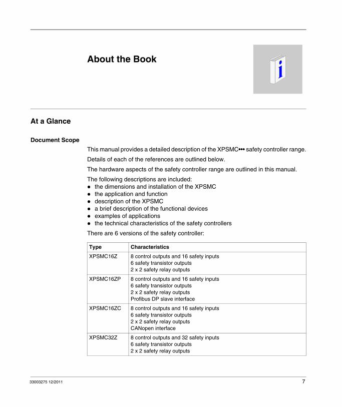
This manual provides a detailed description of the XPSMC••• safety controller range.
Details of each of the references are outlined below.
The hardware aspects of the safety controller range are outlined in this manual.
The following descriptions are included:the dimensions and installation of the XPSMCthe application and functiondescription of the XPSMCa brief description of the functional devicesexamples of applicationsthe technical characteristics of the safety controllers
There are 6 versions of the safety controller:
Type Characteristics
XPSMC16Z 8 control outputs and 16 safety inputs6 safety transistor outputs2 x 2 safety relay outputs
XPSMC16ZP 8 control outputs and 16 safety inputs6 safety transistor outputs2 x 2 safety relay outputsProfibus DP slave interface
XPSMC16ZC 8 control outputs and 16 safety inputs6 safety transistor outputs2 x 2 safety relay outputsCANopen interface
XPSMC32Z 8 control outputs and 32 safety inputs6 safety transistor outputs2 x 2 safety relay outputs
33003275 12/2011 7

Validity Note
The corresponding configuration software is XPSMCWIN under Microsoft Windows 2000/XP/Vista/7.
The XPSMC safety controller has been developed and manufactured in accordance with European standards and directives.
NOTE: The corresponding declaration of conformity is provided in Appendix E of this document (see page 157).
The product manufacturer possesses a certified quality assurance system in accordance with EN ISO 9001.
The technical characteristics of the device(s) described in this manual also appear online. To access this information online:
The characteristics presented in this manual should be the same as those that appear online. In line with our policy of constant improvement we may revise content over time to improve clarity and accuracy. In the event that you see a difference between the manual and online information, use the online information as your reference.
XPSMC32ZP 8 control outputs and 32 safety inputs6 safety transistor outputs2 x 2 safety relay outputsProfibus DP slave interface
XPSMC32ZC 8 control outputs and 32 safety inputs6 safety transistor outputs2 x 2 safety relay outputsCANopen interface
Type Characteristics
Step Action
1 Go to the Schneider Electric home page www.schneider-electric.com.
2 In the Search box type the model number of a product or the name of a product range.Do not include blank spaces in the model number/product range.To get information on a grouping similar modules, use asterisks (*).
3 If you entered a model number, go to the Product datasheets search results and click on the model number that interests you.If you entered the name of a product range, go to the Product Ranges search results and click on the product range that interests you.
4 If more than one model number appears in the Products search results, click on the model number that interests you.
5 Depending on the size of your screen, you may need to scroll down to see the data sheet.
6 To save or print a data sheet as a .pdf file, click Download XXX product datasheet.
8 33003275 12/2011

Related Documents
You can download these technical publications and other technical information from our website at www.schneider-electric.com.
Product Related Information
The English version of this Hardware Manual is the original document. Publications in any other language are translations of this original English document.
1 For additional information, refer to NEMA ICS 1.1 (latest edition), "Safety Guidelines for the Application, Installation, and Maintenance of Solid State Control" and to NEMA ICS 7.1 (latest edition), "Safety Standards for Construction and Guide for Selection, Installation and Operation of Adjustable-Speed Drive Systems" or their equivalent governing your particular location.
Title of Documentation Reference Number
Configuration Software for XPSMC 33003281
WARNINGLOSS OF CONTROL
The designer of any control scheme must consider the potential failure modes of control paths and, for certain critical control functions, provide a means to achieve a safe state during and after a path failure. Examples of critical control functions are emergency stop and overtravel stop, power outage and restart.Separate or redundant control paths must be provided for critical control functions.System control paths may include communication links. Consideration must be given to the implications of unanticipated transmission delays or failures of the link.
Observe all accident prevention regulations and local safety guidelines.1
Each implementation of this equipment must be individually and thoroughly tested for proper operation before being placed into service.
Failure to follow these instructions can result in death, serious injury, or equipment damage.
33003275 12/2011 9

DANGERHAZARDOUS VOLTAGE
Only trained professional electricians may install, startup, modify, and retrofit this equipment!
Disconnect the device / system from all power sources prior to starting any work!
If installation or system errors occur, line voltage may be present at the control circuit in devices without DC isolation!
Observe all electrical safety regulations issued by the appropriate technical authorities or the trade association. The safety function can be lost if the device is not used for the intended purpose.
Opening the housing or any other manipulation will void the warranty
Failure to follow these instructions will result in death or serious injury.
CAUTIONUNINTENDEND USE
If the device has been subjected to improper or incorrect use it must no longer be used, and the guarantee loses its validity.
Impermissible conditions include:
strong mechanical stress, for example through a fall, or voltages, currents, temperatures or humidity outside of the specifications.
Before starting up your machine/plant for the first time, please be sure to check all the safety functions according to valid regulations, and observe the specified test cycles for safety equipment.
Failure to follow these instructions can result in injury or equipment damage.
10 33003275 12/2011

User Comments
We welcome your comments about this document. You can reach us by e-mail at [email protected].
CAUTIONRISKS ON INSTALLATION
Perform the following precautionary steps prior to installation, assembly or disassembly:1. Disconnect supply voltage to the equipment / system prior to starting any work.2. Lockout/tag the equipment / system to prevent accidental activation.3. Confirm that no voltage is present.4. Ground the phases and short to ground.5. Protect against adjacont live components using guards and barriers.
Failure to follow these instructions can result in injury or equipment damage.
DANGERHAZARD OF ELECTRIC SHOCK, EXPLOSION OR ARC FLASH
Disconnect all power from all equipment including connected devices prior to removing any covers or doors, or installing or removing any accessories, hardware, cables, or wires except under the specific conditions specified in the appropriate hardware guide for this equipment.Always use a properly rated voltage sensing device to confirm the power is off where and when indicated.Replace and secure all covers, accessories, hardware, cables, and wires and confirm that a proper ground connection exists before applying power to the unit.Use only the specified voltage when operating this equipment and any associated products.
Failure to follow these instructions will result in death or serious injury.
CAUTIONRATED PROTECTION AGAINST ACCIDENTAL CONTACT
Protection type according to EN/IEC 60529.Housing/terminals: IP 20 / IP 20.Finger-proof acc. to EN 50274.
Failure to follow these instructions can result in injury or equipment damage.
33003275 12/2011 11

12 33003275 12/2011

33003275 12/2011
1
XPSMC
Functional Safety Information
33003275 12/2011
Functional Safety Information
What’s in this Chapter?
This chapter contains the following topics:
Topic Page
IEC 61508 and Safety Integrity Level (SIL) 14
Functional Safety Certification 15
Training 18
13

Functional Safety Information
IEC 61508 and Safety Integrity Level (SIL)
Introduction
The XPSMC safety controllers are a Safety-Related System certified according to IEC 61508 by TÜV NORD CERT GmbH.
IEC 61508 Description
The IEC 61508 is a technical standard concerning the Functional Safety of electrical, electronic or programmable electronic Safety-Related Systems.
A Safety-Related System is a system that is required to perform 1 or more specific functions to ensure risks are kept at or below an acceptable level. Such functions are defined as Safety Functions.
A system is defined functionally Safe if random, systematic, and common cause failures do not lead to malfunctioning of the system and do not result in injury or death of humans, spills to the environment, and loss of equipment and production.
Description of the Safety Integrity Level (SIL)
Safety Functions are executed to achieve and maintain the Safe state of a system. The IEC 61508 specifies 4 levels of Safety performance for a Safety Function. These are called Safety Integrity Levels (SIL), ranging from 1 (the lowest) to 4 (the highest). The XPSMC controllers are certified for use in SIL 3 applications in which the de-energized state is the Safe state, for example in an emergency shutdown (ESD) system.
14 33003275 12/2011

Functional Safety Information
Functional Safety Certification
Introduction
The XPSMC controllers are certifiedby TÜV NORD CERT GmbHfor use in applications up to and including SIL 3 according to IEC 61508 and IEC 62061.
This certification verifies that the XPSMC is compliant with the following standards and directives:
2006/42/ECEN 60204-1:2006EN ISO 13849-1:2008, PL eEN / IEC 61508:2001, SIL 3EN 62061:2005, SILCL 3EN 60947-5-1:2004 chapter 4.4 Categories for switching elementsEN 61496-1:2004+A1:2008 annex A.7 MutingEN 574:1996+A1:2008, Typ IIIa, Typ IIIcEN 692:2005+A1:2009, chapter 5.4.1EN 693:2001+A1:2009, chapter 5.4.1
NOTE: Please visit our website www.schneider-electric.com for a copy of the most recent version of the certificate. Also refer to Decleration of Conformity (see page 157).
NOTE: Using a XPSMC safety controller is a necessary but not sufficient precondition for the certification of a SIL 3 application. A SIL 3 application must also fulfill the requirements of the IEC 61508, and other application standards.
Functional Safety Parameters
Values for safety relay outputsaccording to EN ISO / ISO 13849-1
PL e / Category 4MTTFd = 71 YearsDC > 99%
according to EN / IEC 62061
PFHd = 1,4 x 10⁻⁸ 1/hSILCL 3
Values for safety transistor outputsaccording to EN ISO / ISO 13849-1
PL e / Category 4MTTFd = 76,6 YearsDC > 99%
33003275 12/2011 15

Functional Safety Information
according to EN / IEC 62061
PFHd = 1,29 x 10⁻⁸ 1/hSILCL 3
NOTE:
The performance level and safety category in accordance with EN ISO / ISO 13849-1 depends on the external wiring, the application case, the choice of control station and how this is physically arranged on the machine.The user must carry out a risk assessment in accordance with EN ISO / ISO 12100.The entire system/machine must undergo validation in accordance with the applicable standards.The module contains electro-mechanical relays. This is why actual MTTFd values will vary depending on the application load and duty cycle. The estimated MTTFd values in years mentioned above are based on the following assumptions:
B10d value for maximum load of 400,000average switching quantity nop=6,300 cycles/yearB10d value for low load of 20,000,000average switching quantity nop=361,800 cycles/year(see EN ISO / ISO 13849-1, C.2.4 and Tab K.1)
You must ensure that the loads and switching cycles experienced by the safety relay are appropriate for the calculated performance level. Use the Electrical Life of the Output Contacts diagrams (see page 131) to calculate the maximum acceptable values. Make frequent observations of the operating conditions and replace the module before these limits are exceeded. The specified performance level can only be assured for the number of switching cycles calculated using this method. In no case should you exceed a service life of 20 years.Operating the device not within the specifications may lead to unintended behavior or the destruction of the device.Please consult the installation notes.
NOTE: There are no user serviceable components in the module.
16 33003275 12/2011

Functional Safety Information
CAUTIONRESIDUAL RISK (EN ISO / ISO 12100-1)
These controllers must be used for safety-related functions in conjunction with the connected safety equipment and devices that meet applicable standard requirements.
A residual risk will remain if:it is necessary to modify this recommended circuit and if the added/ modified components are not properly integrated in the control circuit.the user does not follow the required standards applicable to the operation of the machine, or if the adjustments to and maintenance of the machine are not properly made. It is essential to strictly follow the prescribed machine maintenance schedule.the devices connected to the safety outputs do not have mechanically-linked contacts.
Failure to follow these instructions can result in injury or equipment damage.
33003275 12/2011 17

Functional Safety Information
Training
Introduction
As stated in the IEC 61508, Part 1, App. B, all persons involved in a Safety Lifecycle activity must have the appropriate training, technical knowledge, experience, and qualifications relevant to the specific duties they have to perform. This should be assessed in relation to each particular application.
NOTE: Make sure you possess all information and skills required to install, run, and maintain Safety-Related Systems correctly.
Qualification of Personnel
Electrical equipment should be installed, operated, serviced, and maintained only by qualified personnel. No responsibility is assumed by Schneider Electric for any consequences arising out of the use of this material.
A qualified person is one who has skills and knowledge related to the construction and operation of electrical equipment and the installation, and has received safety training to recognize and avoid the hazards involved.
The specialists must be able to detect possible hazards that may arise from parameterization, changing parameter values and generally from mechanical, electrical or electronic equipment. The specialists must be familiar with the standards, provisions and regulations for the prevention of industrial accidents, which they must observe when working on the drive system.
Training Contents
In addition to the usual training courses concerning the use of the company’s products, Schneider Electric offers you training courses covering the topics of its IEC 61508 compliant Safety-Related System.
18 33003275 12/2011

33003275 12/2011
2
XPSMC
Overview
33003275 12/2011
Overview: XPSMC16Z/ZC/ZP, XPSMC32Z/ZC/ZP
Overview
This chapter contains an overview of the safety controllers XPSMC16Z, XPSMC16ZC, XPSMC16ZP, XPSMC32Z, XPSMC32ZC, and XPSMC32ZP.
What’s in this Chapter?
This chapter contains the following topics:
Topic Page
XPSMC Models 20
Representation 22
Dimensions 24
Installation 25
19

Overview
XPSMC Models
XPSMC
XPSMC is a generic term that describes the entire family of different XPSMC safety controllers. Currently, the following models are available: XPSMC16Z, XPSMC16ZC, XPSMC16ZP, XPSMC32Z, XPSMC32ZC, and XPSMC32ZP.
Differences Between XPSMC Models
XPSMC safety controllers
XPSMC•• Package Content
The XPSMC•• Package consists of the following items:
Model Modbus RTU Serial
CANopen Profibus DP No. of Inputs and Outputs
XPSMC16Z x – – 8 control outputs and 16 safety inputs
XPSMC16ZC x x – 8 control outputs and 16 safety inputs
XPSMC16ZP x – x 8 control outputs and 16 safety inputs
XPSMC32Z x – – 8 control outputs and 32 safety inputs
XPSMC32ZC x x – 8 control outputs and 32 safety inputs
XPSMC32ZP x – x 8 control outputs and 32 safety inputs
Details about the safety controller functionality can be found within the Device Set chapter (see page 114).
Hardware XPSMC*Z* Safety Controller
Manuals Printed English Manual
Documentation CD Hardware Manuals (PDF) in: English, German, French, Spanish, Portuguese
20 33003275 12/2011

Overview
To configure and commission the safety controller you also require the following items (1 reference for each item):
Item References
Configuration software XPSMCWIN configuration software XPSMCWIN
Configuration cable USB PC adaptor and Ethernet connection cable (2 references) or
TSXCUSB485 + 490NTW00002
Serial PC adaptor and connection cable (2 references)
TSXPCX1031 + XPSMCCPC
IO terminals Screw terminals pack available for 16 or 32 Digital Input versions of the Safety Controller (Terminals provided for the complete safety controller)For Safety Controller:1. References 16 Digital Input:
XPSMC16Z, XPSMC16ZC, XPSMC16ZP
2. References 32 Digital Input: XPSMC32Z, XPSMC32ZC, XPSMC32ZP
You require 1 of the following references: 1. XPSMCTS162. XPSMCTS32
Cage Clamp terminals pack available for 16 or 32 Digital Input versions of the safety controller (Terminals provided for the complete safety controller)For Safety Controller:1. References 16 Digital Input:
XPSMC16Z, XPSMC16ZC, XPSMC16ZP
2. References 32 Digital Input: XPSMC32Z, XPSMC32ZC, XPSMC32ZP
1. XPSMCTC162. XPSMCTC32
Power Supply IEC EN 60950 rated powers supply with protective separation (PELV, or SELV)1. 3A, 24 VDC 2. 5A, 24 VDC3. 10A, 24 VDC
1. ABL8RPS240302. ABL8RPS240503. ABL8RPS24100
33003275 12/2011 21

Overview
Representation
Front View XPSMC16Z / 32Z
The following image shows the front view of the XPSMC16Z and XPSMC32Z:
1 16 additional safety inputs of XPSMC32Z
22 33003275 12/2011

Overview
Front View XPSMC16ZP / 16ZC/ 32ZP / 32ZC
The following image shows the front view of the XPSMC16ZP , XPSMC16ZC, XPSMC32ZP and XPSMC32ZC:
1 16 additional safety inputs of XPSMC32ZP and XPSMC32ZC2 Profibus DP female connector (XPSMCZP) or CANopen male connector (XPSMCZC)
33003275 12/2011 23

Overview
Dimensions
Dimensions of the XPSMC
The following figures show the dimensions of the XPSMC (mm/in):
1 When using XPSMCTS• connectors this dimension is 153 mm (6.02 in) When using XPSMCTC• connectors this dimension is 151,5 mm (5.96 in)
24 33003275 12/2011
Overview
Installation
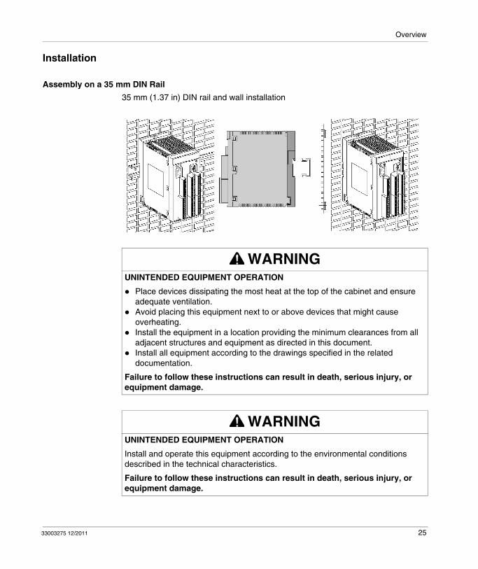
Assembly on a 35 mm DIN Rail
35 mm (1.37 in) DIN rail and wall installation
WARNINGUNINTENDED EQUIPMENT OPERATION
Place devices dissipating the most heat at the top of the cabinet and ensure adequate ventilation.Avoid placing this equipment next to or above devices that might cause overheating.Install the equipment in a location providing the minimum clearances from all adjacent structures and equipment as directed in this document.Install all equipment according to the drawings specified in the related documentation.
Failure to follow these instructions can result in death, serious injury, or equipment damage.
WARNINGUNINTENDED EQUIPMENT OPERATION
Install and operate this equipment according to the environmental conditions described in the technical characteristics.
Failure to follow these instructions can result in death, serious injury, or equipment damage.
33003275 12/2011 25

Overview
This equipment has been designed to operate outside of any hazardous location. Only install this equipment in zones known to be free of a hazardous atmosphere.
Disassembling from 35 mm (1.37 in.) DIN rail
NOTE: The XPSMC is grounded through an attachment plate or a DIN rail.
Requirements
The controller should be air-cooled by natural convection. To facilitate ventilation, install it vertically with the ventilation louvers on the bottom and on the top.
If several controllers are installed on the same rack, it is recommended that the following provisions be observed:
Leave a free space of at least 150 mm (5.90 in.) for the ducts, wiring, and air circulation above and below the controller.Install heat-generating devices (transformers, supply modules, power switches, etc.) above the controllers.
DANGEREXPLOSION HAZARD
This equipment is suitable for use in non-hazardous locations only.
Failure to follow these instructions will result in death or serious injury.
26 33003275 12/2011

Overview
Disassembly of the Upper Housing
Removal of the upper housing section from the mounting plate (torque value = 1.1 Nm (9.7 lb-in)).
Assembly of the upper housing section on to the mounting plate (torque value = 1.1 Nm (9.7 lb-in)).
33003275 12/2011 27

Overview
28 33003275 12/2011

33003275 12/2011
3
XPSMC
Application and Function
33003275 12/2011
Application and Function
Overview
This chapter described the application and function of XPSMC16Z, XPSMC16ZC, XPSMC16ZP, XPSMC32Z, XPSMC32ZC, and XPSMC32ZP safety controllers.
What’s in this Chapter?
This chapter contains the following topics:
Topic Page
Application 30
Function 31
Initial Operation 34
29

Application and Function
Application
Description
The XPSMC device is an electronic safety controller for the monitoring of safety functions up to safety category 4, PL e, according to EN ISO / ISO 13849-1 and SILCL 3 according to EN / IEC 62061 respectively SIL 3 according to EN / IEC 61508 in the section for machine safety.
The XPSMC Safety Controller has 6 solid state transistor outputs and in addition 2 safety relay outputs, and depending on version either 16 or 32 digital inputs.
The safety controller contains a configuration interface (TER).
The TER interface is a Modbus RTU serial communications port which can also be used for diagnostic purposes as it can be connected to a standard PLC or a graphical user interface (for example HMI Magelis).
Additional references of the safety controller contain either CANopen or Profibus DP interfaces.
NOTE: Every connected sensor and actuator to the XPSMC must change its status once between 2 machine service intervals or at least once a year. This must be done, as the Safety Integrity Level calculation for each safety function is based upon a complete input/output test once a year.
NOTE: The device contains no components which require maintenance by the user. For authorization of safety circuits in accordance with EN / IEC 60204, EN ISO / ISO 13850, only the output circuits between terminals 13-14, 23-24, 33-34, 43-44 and semiconductor safety outputs o1 to o6 can be used.
30 33003275 12/2011

Application and Function
Function
Description
The device includes 6 independent semiconductor safety outputs and 2 independent groups of dual channel positively driven potential-free contact safety relay outputs. Each of the 4 channels has 2 contacts in series.
Electromagnetic radiation may interfere with control communications and/or input/output signals to the control system.
Functions of XPSMC
The XPSMC has 8 control outputs, c1 to c8 and 16 (32) safety inputs, i1 to i16 (i1 to i32).
The safety inputs are monitored for cross connections and short circuits by supplying the circuit members with different control outputs, c1 to c8.
The safety controller uses the control outputs to continuously test the connected inputs including their power connections.
If an error is detected on the input circuit, the control logic switches off the safety outputs associated with the relevant safety function. The safety outputs associated with other safety functions continue to operate normally.
XPSMC safety controllers are equipped with a Modbus RTU serial interface (TER).
NOTICERADIO INTERFERENCE
This product is a Class A (FCC/VDE) product intended for use in industrial environments. Do not use this product in Class B domestic environment applications.
Failure to follow these instructions can result in equipment damage.
WARNINGUNINTENDED EQUIPMENT OPERATION
Do not wire I/O and communication lines in proximity to power cables, radio devices, or other equipment that may cause electromagnetic interference.If wiring of I/O lines near power lines or radio equipment is unavoidable, use shielded cables. Properly ground the cable shields as indicated in the related documentation.
Failure to follow these instructions can result in death, serious injury, or equipment damage.
33003275 12/2011 31

Application and Function
In addition a CANopen interface is available onXPSMC16ZCXPSMC32ZC
and a Profibus DP interface is available onXPSMC16ZPXPSMC32ZP
The communication ports are to provide diagnostic information regarding the status of the controller. The communication is non-safety related. The safety controller is a slave for all communication possibilities.
XPSMC
WARNINGLOSS OF CROSS-CONNECTION DETECTION
Carefully analyze and understand how the circuits which are sharing control outputs interact in your application. Short-circuits between inputs driven by the same control outputs are not detected. You have to ensure that no hazardous condition can occur.
Failure to follow these instructions can result in death, serious injury, or equipment damage.
32 33003275 12/2011

Application and Function
NOTE: Damage to property or injury due to improper circuit-connections voids warranties and does not make Schneider Electric liable.
The following recommendations have been thoroughly tested and checked in operational conditions. They meet the requirements of the relevant standards, with connected peripheral equipment of safety installations and switching equipment.
Configuration of XPSMC
The XPSMC is configured using a PC (computer) and the XPSMCWIN configuration software.
The connection between the safety controller and PC (computer) can be made in 2 ways (see page 43):
using the serial communication port from the PC (computer)using the USB communication port from the PC (computer)
DANGERUNINTENDED EQUIPMENT OPERATION OR ELECTRIC SHOCK
Be sure to connect the terminal blocks to their designated location.
Failure to follow these instructions will result in death or serious injury.
DANGERIMPROPER CIRCUIT DESIGN, TESTING AND SERVICING HAZARD
Ensure safety equipment or devices are sufficiently engaged in the switch safety process when deviating from the recommended circuit design.Strict compliance with the recommended testing and servicing intervals for the machine is required.Strict compliance with the relevant safety instructions concerning machine operation, adjustment and servicing is required.Refer to EN ISO / ISO 12100.
Failure to follow these instructions will result in death or serious injury.
33003275 12/2011 33

Application and Function
Initial Operation
Auto-test (factory settings)
The XPSMC is delivered in a non-configured state. On first power up it performs an internal test which lasts approximately 2 seconds. To connect the power to the safety controller connect +24 VDC to terminal A1 and 0 VDC to terminal A2.
Auto-test (hardware test)
You can reset the configuration of an XPSMC as follows: Disconnect the XPSMC from power supply, press and hold the Reset button while you reconnect the XPSMC to the power supply. The configuration will no longer be valid however, it is possible to read the configuration from the controller on the computer and revalidate the configuration.
Auto-test (with a valid configuration)
Power cycle the XPSMC with a valid configuration.
Stage Description
1 The LEDs located on the housing light up.
2 After 2 secondsPWR LED is onCNF LED is flashingremaining LEDs are off
Stage Description
1 The LEDs located on the housing light up.
2 After 2 seconds, the LEDs switch off for a short time and then on again, since the Reset button is pressed.
3 Release the Reset button.PWR LED is onCNF LED is flashingremaining LEDs are off
Stage Description
1 The LEDs located on the housing light up.
2 After 2 secondsPWR LED is onRUN LED is on when the controller was in Run before power cycleRUN LED is off when the controller was in Stop before power cycle
If the controller has fieldbus interfaces then:CANopen/Profibus DP LEDs (RUN and ERR) behavior depends on the connection (see Elements of the Display and System Diagnostics, page 48).
34 33003275 12/2011

Application and Function
Downloading a New Configuration
The XPSMC is delivered in a non-configured state, and the device must be configured to render it operational. The configuration is performed using software XPSMCWIN.
NOTE: The XPSMCWIN software manual contains a detailed description of the safety functions available from the XPSMC safety controller.
Once the XPSMC safety controller has been successfully configured and validated, it can be set into RUN mode with the XPSMCWIN software.
DANGERDANGEROUS MOVEMENT
Evaluate operational state of all outputs before setting the XPSMC safety controller into RUN mode with the XPSMCWIN software.
You must make sure that no unintended equipment operation can occur.
Failure to follow these instructions will result in death or serious injury.
Stage Description
1 After downloading a valid configurationCNF LED is off
2 After setting the XPSMC safety controller into run mode:RUN LED is onLEDs corresponding to the inputs and outputs light up as a function of their status
If the controller has fieldbus interfaces then:CANopen/Profibus LEDs - behavior depends on the connection (see Elements of the Display and System Diagnostics, page 48)
The XPSMC is now operational.
33003275 12/2011 35

Application and Function
36 33003275 12/2011

33003275 12/2011
4
XPSMC
XPSMC Description
33003275 12/2011
XPSMC Description
Overview
This chapter contains the description of the safety controllers XPSMC16Z, XPSMC16ZC, XPSMC16ZP, XPSMC32Z, XPSMC32ZC, and XPSMC32ZP.
What’s in this Chapter?
This chapter contains the following sections:
Section Topic Page
4.1 General Description of the XPSMC16/32 38
4.2 Modbus RTU Communication 61
4.3 Description of Profibus DP Parameter and Settings 87
4.4 Description of CANopen Parameter and Settings 93
37

XPSMC Description
4.1 General Description of the XPSMC16/32
Introduction
This section provides an overview of the general functions and properties of the XPSMC16/32 Safety Controller.
What’s in this Section?
This section contains the following topics:
Topic Page
Front View of XPSMC 39
Communication Connections TER 43
Elements of the Display and System Diagnostics 48
Connection Diagram 50
Technical Characteristics 52
Error Codes 59
38 33003275 12/2011

XPSMC Description
Front View of XPSMC
Overview
The following images represent the XPSMC models with screw terminals (ref: XPSMCTS) or cage clamp terminals (ref: XPSMCTC).
Front View XPSMCZ
1 Terminals2 TER connection3 Reset button
33003275 12/2011 39

XPSMC Description
Front View XPSMCZP and XPSMCZC
1 Terminals2 Fieldbus connection (Profibus DP(female connector) or CANopen (male connector))3 TER connection4 Reset button
Keying of the Terminal Connectors Connector 1...4
The terminal connectors Connector 1...4 can be keyed by inserting the code profiles into the slots of the controller’s connectors and breaking off the appropriate tabs of the cable connector.
Display
The LED indicators reflect the current operating status of the device (see chapter Elements of the Display and System Diagnostics, page 48).
40 33003275 12/2011

XPSMC Description
Terminals
The terminal layout is as follows:
Connection
8 pin RJ45 connector is used to connect the XPSMC safety controller to a PC for configuration and/or diagnostics.
The communication via the TER terminal is Modbus RTU protocol and can also be used to connect to a HMI Magelis operating terminal, or a standard PLC.
Fieldbus Connection
Dependant on version:Profibus DP: 9 pin D-Sub female connectorCANopen: 9 pin D-Sub male connector
Reset Button
When an external error was detected and assumed to be fixed, this has to be confirmed by pressing the Reset button. When the error is no longer detected, the controller will be able to enter the RUN mode again
Pressing the Reset button during a power cycle will reset the XPSMC controller to default values. As a result the password is set to ’safety’, and the configuration is invalid but not deleted. That means the controller cannot be set to RUN mode anymore but the configuration and protocol can still be read from controller. To set the controller operational again, the controller needs to be reconfigured (download and validate a configuration).
Terminal Layout Meaning
A1-A2 24V power supply; A1 is the + pole (+24 VDC), A2 is the - pole (0 VDC, GND)
GND It is identical to the 0 VDC potential on A2 for loads on the o1-o6 semiconductor safety outputs.
o1-o6 semiconductor safety outputs
13-44 potential-free safety relay outputs equipped with contacts
c1-c8 control outputs for safety input power supplyThe control outputs provide a signal that enables detection of short circuit and detection of voltage intrusion for the connected control components.
i1-i16 or i1-i32 safety inputs
H1 connection for muting lampThe supply voltage must be taken from the same source which supplies the XPSMC.
33003275 12/2011 41

XPSMC Description
CANopen/Profibus DP LEDs
Two LEDs for CANopen/Profibus DP connection: RUN (green) and ERR (red).
Refer to Profibus DP LEDs, page 90 for Profibus DP and to CANopen LEDs, page 96 for CANopen LED description.
42 33003275 12/2011

XPSMC Description
Communication Connections TER
Connection
8 pole RJ45-Socket pin-outs
Connection to a PC for Configuration
There are 2 ways to connect the safety controller to the PC (computer):using the serial communications interface from the PCusing the USB communications interface from the PC
Serial Connection
The following 2 cabling components are required to set up the serial connection:XPSMCCPC adaptorTSXPCX1031 serial adaptor
NOTE: These accessories need to be ordered separately.
8 Pole RJ45-Socket, with Protection
Pin Signal Description
Representation: 1 – –
2 – –
3 DPT TER Port Mode Control
4 D1 (B) RS485 Signal
5 D0 (A) RS485 Signal
6 /DE Negative Data Transmit Enable
7 5V Logical VCC
8 0V Ground
33003275 12/2011 43

XPSMC Description
The following figure shows the physical serial connection from the PC to the XPSMC safety controller.
1 XPSMCCPC2 TSXPCX1031
USB Connection
The following 2 cabling components are required to set up the USB connection:
Standard (1:1) RJ45/RJ45 twisted pair Category 5D Ethernet cable Ref: 490NTW00002TSXCUSB485 USB adaptor
NOTE: These accessories are included in the XPSMC*PACK or may be ordered separately.
In addition you will require the USB driver pack available on the Safety Suite V2 (XPSMCWIN) software CD or on www.schneider-electric.com.
Driver pack installation instructions are available within the software manual.
44 33003275 12/2011

XPSMC Description
The following figure shows the physical USB connection from the PC to the XPSMC safety controller.
1 RJ45-RJ45 twisted pair category 5D or better (1:1) Ethernet cable (e.g. 490NTW00002)2 USB Adaptor TSXCUSB485
Setting of the interface’s cables TSXPCX1031 and TSXCUSB485
Connection to the PC (computer)There are 2 ways to connect the safety controller to the PC:1. Using the serial communications interface
from the PC2. Using the USB communications interface
from the PC
The following cabling components are required to set up the connection:1. Serial connection from PC to the XPSMC
safety controller:XPSMCCPC adaptorTSXPCX1031 serial adaptor
2. USB connection from the PC to communications interface from the PC
Standard (1:1) RJ45/RJ45 twisted pair Category 5D Ethernet cable. Ref. 490NTW00002TSXCUSB485 USB adaptor
Connection of a Magelis HMI Terminal (for ex. XBT)
cable XBT-Z938 or adapter XPSMCCPC + cable XBT-Z968
Connection of a Premium PLC controller (for ex. communication cards: TSXSCY21601 or SCY11601)
cable XPSMCSCY
Representation Switch Position
The switch must be in position 3 OTHER DIRECT
33003275 12/2011 45

XPSMC Description
Connection of One or More XPSMC to a Modbus RTU System
NOTE: It is not possible to program the controller via the LUI9GC3 system. The connection of more than one controller on the network is for use with HMI-Magelis, and the standard PLCs.
The following figure shows the connection of one or more XPSMC to a Modbus RTU system:
Configuration Rules
Every XPSMC must be separately addressed and configured if it is to be used on the same bus.
If the controller is operated within a Modbus network under strong EMC influence the resulting disturbances may lead to unsuccessful bus traffic. To avoid this situation from occurring, we recommend using a snap on ferrite filter on the bus connection.
Follow these recommendations for the Modbus network wiring:Use a shielded twisted pair cable.Connect the reference potentials (ground) to one another.Ensure that the maximum cable length does not exceed 1000 m (3280.8 ft).Ensure that the maximum drop length does not exceed 20 m (65.6 ft).Keep at least 30 cm (1 ft) between the bus cable and the power cable.
46 33003275 12/2011

XPSMC Description
Any crossing of the bus cable and power cables should be made at right angles (90° ).Ground the cable shielding on each unit.Adapt the line at both ends using a line terminator.
NOTICELOSS OF NETWORK
Make sure that devices on a Modbus system have unique network addresses.
Failure to follow these instructions can result in equipment damage.
33003275 12/2011 47

XPSMC Description
Elements of the Display and System Diagnostics
LED Display Fields
XPSMC16 Display
30 LEDs are used to display the operational status of the XPSMC16.
XPSMC32 Display
46 LEDs are used to display the operational status of the XPSMC32.
LED Description
LED Color Significance
PWR green PowerLights up when operational voltage is applied to A1/A2.
CNF yellow ConfigLights up in the configuration mode. Flashes when the XPSMC is not configured, for example during the initial operation. The XPSMC must be configured before operation.
E In red Internal ErrorLights up if an internal error is detected. The safety outputs are immediately deactivated. If the indication is persistent after power cycle and reset then the XPSMC has been damaged and must be replaced.
E Ex red External ErrorLights up when an external error is detected, for example in the wiring. Only the safety outputs of the affected inputs are deactivated. When the detected error has been corrected, and the RESET button has been pressed, the corresponding safety outputs become operational again.
48 33003275 12/2011

XPSMC Description
RUN green RunLights up in the RUN mode. Flashes during the transition from RUN mode to the STOP mode as long as defined delay times are running.
COM green CommunicationLights up during communication via the TER.
o1...o6 green Output 1...6Lights up when the corresponding semiconductor safety output is activated. Flash, when a short circuit, defect or an external fault is detected on this output. In addition the LED E Ex lights up.An error message can be caused by a false signal (e.g. cross circuit connection, external voltage) or when a transistor is non-operational. Disconnect the wire of the concerned output and press the RESET button. If the error message disappears, then the error that was detected is in the wiring. Otherwise, an output transistor is non-operational. In this case, this output must no longer be used.
R1, R2 green Relay group 1/2Lights up when relay group R1 (safety relay outputs 13/14 and 23/24) and/or relay group R2 (safety relay outputs 33/34 and 43/44) are activated. The LED(s) flashes, when a fault is detected on this output. In addition the LED E In lights up. This output must no longer be used.
1...161...32
greengreen
Input i1...i16Input i1...i32Lights up if on the corresponding i1...i16/i32 input circuit is closed. Flashes when an error is detected on this input.
LED Color Significance
33003275 12/2011 49

XPSMC Description
Connection Diagram
Introduction
The following information is provided to help you to connect and wire your XPSMC16 / XPSMC32 safety controller.
Electrical Diagram for XPSMC Devices
DANGERHAZARD OF ELECTRIC SHOCK, EXPLOSION OR ARC FLASH
Disconnect all power from all equipment including connected devices prior to removing any covers or doors, or installing or removing any accessories, hardware, cables, or wires except under the specific conditions specified in the appropriate hardware guide for this equipment.Always use a properly rated voltage sensing device to confirm the power is off where and when indicated.Replace and secure all covers, accessories, hardware, cables, and wires and confirm that a proper ground connection exists before applying power to the unit.Use only the specified voltage when operating this equipment and any associated products.
Failure to follow these instructions will result in death or serious injury.
50 33003275 12/2011

XPSMC Description
The following diagram shows the XPSMC16 / XPSMC32 connection:
Description of terminals:
Terminal Layout Meaning
A1-A2 24 V power supply; A1 is the + pole (+24 V), A2 is the - pole (0 V, GND)
GND It is identical to the 0 V potential on A2 for loads on the o1...o6 semiconductor safety outputs.
c1-c8 control outputs (for the XPSMC32: there are two sets of 8 control outputs available)
i1-i16 or i1-i32 safety inputs
H1 connection for muting lamp
o1-o6 semiconductor safety outputs
13/14, 23/24, 33/34, 43/44
safety relay outputs, potential free
TER 8 pin RJ45 connector for configuration and/or diagnostics.The communication via the TER terminal is Modbus RTU protocol and can also be used to connect to a HMI magelis operating terminal, or a standard PLC.
Fieldbus Dependant on version:Profibus DP: 9 pin D-Sub female connector.CANopen: 9 pin D-Sub male connector.
33003275 12/2011 51

XPSMC Description
Technical Characteristics
XPSMC•, Terminals A1, A2, 13, 14, 23, 24, 33, 34, 43, 44
Single lead connection
Multiple lead connections
WARNINGUNINTENDED EQUIPMENT OPERATION
Do not exceed any of the rated values specified in the following tables.
Failure to follow these instructions can result in death, serious injury, or equipment damage.
Connection Diameters, Single Lead Connection
XPSMCTS / XPSMCTC
Without lead end sleeves solid 0.2 - 2.5 mm2
stranded 0.2 - 2.5 mm2
(24 - 12 AWG)
Stranded with lead end sleeves (without plastic sleeves)
0.25 - 2.5 mm2
(22 - 14 AWG)
Stranded with lead end sleeves (with plastic sleeves)
0.25 - 2.5 mm2
(22 - 14 AWG)
Connection Diameters, Multiple Lead Connections (2 leads max. same diameters)
XPSMCTS XPSMCTC
Without lead end sleeves solid 0.2 - 1.5 mm2
(24 - 16 AWG)stranded
0.2 - 1.5 mm2
(24 - 16 AWG)
-
-
Stranded with lead end sleeves (without plastic sleeves)
0.20 - 1.5 mm2
(22 - 18 AWG)
-
Stranded with twin lead end sleeves (with plastic sleeves)
0.5 - 1.5 mm2
(20 - 16 AWG)0.5 - 1 mm2
(20 - 18 AWG)
52 33003275 12/2011

XPSMC Description
Miscellaneous
NOTE: AWG indication according to EN / IEC 60947-1 / table 5.
XPSMC•, Other Terminals
Single lead connection
Multiple lead connections
Miscellaneous
NOTE: AWG indication according to EN / IEC 60947-1 / table 5.
Stripping length 10 mm (0.39 in)
Tightening torque 0.5 - 0.6 Nm(4.2 - 5.3 lb-in)
-
Connection Diameters, Single Lead Connection
XPSMCTS• / XPSMCTC•
Without lead end sleeves solid 0.14 - 1.5 mm2
stranded 0.14 - 1.5 mm2
(28 - 16 AWG)
Stranded with lead end sleeves (without plastic sleeves)
0.25 - 1.5 mm2
(22 - 16 AWG)
Stranded with lead end sleeves (with plastic sleeves)
0.25 - 0.5 mm2
(22 - 20 AWG)
Connection Diameters, Multiple Lead Connections (2 leads max. same diameters)
XPSMCTS• XPSMCTC•
Without lead end sleeves solid 0.14 - 0.5 mm2
(28 - 20 AWG)stranded
0.14 - 0.75 mm2
(28 - 18 AWG)
-
-
Stranded with lead end sleeves (without plastic sleeves)
0.25 - 0.34 mm2
(22 AWG)
-
Stranded with twin lead end sleeves (with plastic sleeves)
0.5 mm2
(20 AWG)
-
Stripping length 9 mm (0.35 in)
Tightening torque 0.5 - 0.6 Nm(1.9 - 2.2 lb-in)
-
33003275 12/2011 53

XPSMC Description
Mechanical Structure
Power Supply
Excess voltage category III (4 kV) pollution category 2 / Isolation voltage 300 V as per EN / IEC 60664-1
Enclosure Mounting Metal adapter for mounting on 35 mm (1.37 in.) standard DIN rails as per EN / IEC 60715 and screw mounting.
Use a DIN rail with a thickness of 1.5 mm (0.06 in.) up to 2 g (0.07 oz) vibration requirements.Use the fixed mounting directly on a metal plate above 2 g (0.07 oz) vibration requirements.
Protection, as per EN / IEC 60529, TerminalsProtection, as per EN / IEC 60529, Housings
IP 20IP 20
Weight XPSMCT•16Weight XPSMCT•32Weight XPSMC16ZWeight XPSMC32ZWeight XPSMC16Z•Weight XPSMC32Z•
0.08 kg (0.18 lb)0.11 kg (0.24 lb)0.82 kg (1.81 lb)0.84 kg (1.83 lb)0.83 kg (1.85 lb)0.85 kg (1.87 lb)
Assembly Position Ventilation louver on the top and on the bottom, see chapter Installation, page 25.
Ambient Operational Temperature -10 oC / +55 oC (+14 oF / +131 oF)
Storage Temperature -25 oC / +85 oC (-13 oF / +185 oF)
Shock Resistance 150 m/s2
duration 11 msforms half sine
Vibration Resistance 0.5 mm2
from 10 to 55 Hz
Supply UE as per IEC 60038 24V (+ 20%) including ripple
Time between power off and on > 5 s
Short-Circuit Protection, max. Fuse Element Type gL
16 A
Consumption < 12 W
Max. Current Consumption, including Peripherals
8 A
54 33003275 12/2011

XPSMC Description
Safety Relay Outputs
The following table provides technical data on safety-relay outputs:
The following table provides technical data on safety static outputs:
Max. Current per Relay Output 6 A
Safety Relay Outputs, Potential Free 13...14, 23...24, 33...34, 43...44
Max. Switching Capacity of Potential-Free Safety Relay Outputs
AC15 - C300Ue = 230 Vac / Ie = 0.75 ADC13Ue = 24 Vdc / Ie = 1.5 A
Cumulative Current Limit for Concurrent use of several Relay Output Circuits:
∑ lth ≤ 16 ALoad examples:
Short-Circuit Protection, max. Fuse Element for Potential-Free Safety Output Circuits
4 A (gL) or 6 A fastblow
Semiconductor Safety Outputs, NO o1, o2, o3, o4, o5, o6
Max. Current per Semiconductor Safety Outputs 2 A
Voltage Drop of the Semiconductor Safety Outputs
0.25 V (typ.)
Minimum Operating Current of the Semiconductor Safety Outputs
0.8 mA
Leakage Current of Safety Semiconductor Outputs
Breaking Capacity of the Semiconductor Safety Outputs
DC-13 SQ 24 V(SQ is defined in EN / IEC 60947-5-1 table A3)
Conditional short circuit current of the Semiconductor Safety Outputs
100 A
33003275 12/2011 55

XPSMC Description
In the XPSMC16Z, XPSMC16ZC, XPSMC16ZP, XPSMC32Z, XPSMC32ZC, XPSMC32ZP you have the possibility to select between 20 ms and 30 ms for the response times. Selecting the 30 ms response time enables you to configure more functions within the configuration.
Response time <= 20 ms
Response time <= 30 ms
The potential-free safety outputs are also suitable for small loads (min. 17 V / 10 mA). This is, however, only possible if high loads have not already been switched via the contacts, as the contact surface treatment (gold plating) may have been burned off.
Input Circuits
Cumulative Current Limit for Concurrent use of several Semiconductor Outputs
∑ lth ≤ 6.5 AExamples:
Short-Circuit Protection, max. Fuse Element for Semiconductor Output Circuits
none required, the semiconductor outputs are internally short-circuit-protected
Response Time of the Safety Outputs <= 20 ms
Response Time of the Safety Mat <= 30 ms
Increments of Configurable Times -10 ms, -15%
Response Time of the Safety Outputs <= 30 ms
Response Time of the Safety Mat <= 45 ms
Increments of Configurable Times -15 ms, -15%
Number of Inputs 16 or 32
Maximum Category / Maximum Performance Level as per EN ISO / ISO 13849
4 / PL e
Maximum Safety Level as per EN / IEC 62061 SILCL 3
56 33003275 12/2011

XPSMC Description
Miscellaneous
Connectors
Max. Voltage/Current in Input Circuits 28.8 V / 13 mA
Max. Wire Resistance in Input Circuits
Max. Line Capacitance in Input Circuits 220 nF
Max. Wire Length in Input Circuits 2000 m (6500 ft)
Lamp Muting (source of white light, with a
luminosity of minimum 200 cd/m2 and an
illuminated surface of minimum 1 cm2)
Light bulb (24 V / min. 0.5 W to max. 7.0 W, for example: references DL1-BEB) or LED (24 V / min. 0.5 W to max. 7.0 W, for example: references DL1-BDB1
Magnet Switch Typ XCS-DM•
Switch Floor Typ XY2-TP•
Enabling Device Typ XY2AU•
Screw Terminals for XPSMC16•• (includes Keying Device)
XPSMCTS16
Screw Terminals for XPSMC32•• (includes Keying Device)
XPSMCTS32
Cage Clamp Terminals for XPSMC16•• (includes Keying Device)
XPSMCTC16
Cage Clamp Terminals for XPSMC32•• (includes Keying Device)
XPSMCTC32
33003275 12/2011 57

XPSMC Description
Terminals
The following table shows the terminals of XPSMC16/32:
The following table explains the layout of the terminals:
Terminal Layout Meaning
A1-A2 24V power supply; A1 is the + pole (+24 VDC), A2 is the - pole (0 VDC, GND)
GND It is identical to the 0 VDC potential on A2 for loads on the o1-o6 semiconductor safety outputs.
o1-o6 semiconductor safety outputs
13-44 potential-free safety relay outputs equipped with contacts
c1-c8 control outputs for safety input power supplyThe control outputs provide a signal that enables detection of short circuit and detection of voltage intrusion for the connected control components.
i1-i16 or i1 to i32 safety inputs
H1 connection for muting lampThe supply voltage must be taken from the same source which also supplies the XPSMC.
58 33003275 12/2011

XPSMC Description
Error Codes
Error Code Dialog Box
The diagnostic window is available within the XPSMCWIN software. Debugging a configuration is simplified using this tool.
Diagnostics are simplified by the error information along with the device index number(s) being provided.
The following image is an example of the diagnostics view mode:
NOTE: The device number/index in brackets [] identifies the devices in the configuration. The indexes for the devices can be found in the configuration tree itself and in the protocol of the configuration.
33003275 12/2011 59

XPSMC Description
Error code numbers and diagnostic hints of the XPSMC:
NOTE: The diagnostic hints are shown in the XPSMCWIN diagnostics. In fieldbus communications only the error codes are transmitted but not the hints.
Code No. Diagnostic Hint Status
1 short-circuit between inputs
error
2 potential hardware problem detected
3 muting error detected
4 override timeout
5 timeout error detected
6 overtravel exceeded
7 short-circuit
8 muting lamp non-operational
9 cam switch mechanism non-operational
10 press safety valve non-operational
11 external voltage detected
12 output will not switch ON
13 potential shaft / chain problem detected
16 reset button blocked
indication
17 timeout
18 incomplete opening
19 start interlock active
20 open circuit
21 delay time running
22 check locking device
23 check valve
24 unexpected muting signal
25 sensor activated permanently
26 restart interlock active
27 incomplete closing
28 no mode selection
29 reoperate safety means
30 open and close command active
31 Emergency Stop pressed
60 33003275 12/2011

XPSMC Description
4.2 Modbus RTU Communication
General
This section describes how to connect your XPSMC hardware for Modbus RTU. It lists the cables required for connection to either HMI Magelis terminals or Premium PLCs, provides a configuration example to a Premium PLC and lists the respective function codes.
What’s in this Section?
This section contains the following topics:
Topic Page
Cables to Connect the XPSMC Hardware 62
Connecting XPSMC to Premium PLC Modbus Communication Cards 64
Configuring a Premium PLC with Unity for Modbus RTU Communication 67
Importing a Section Including the DFB 73
Viewing Modbus Communications 81
Function Codes and Parameters 84
33003275 12/2011 61

XPSMC Description
Cables to Connect the XPSMC Hardware
Introduction
The following information helps you to select the correct cable to connect your XPSMC hardware for Modbus RTU to either an HMI Magelis or a Premium PLC.
Cable
Connecting XPSMC to a Premium PLC
The figure below illustrates the connection between an XPSMC••Z• and a Premium PLC:
1 XPSMC••Z•2 XPSMCSCY cable3 Premium PLC with SCY21601 Modbus RTU serial interface
Modbus RTU communication set up is the same for the XPSMC references.
Connection of an HMI Magelis terminal cable XBT-Z938 or adapter XPSMCCPC + cable XBT-Z968
Connection to a Premium PLC (Modbus RTU serial card TSXSCY21601 or TSXSCY11601)
XPSMCSCY cable
62 33003275 12/2011

XPSMC Description
Connecting XPSMC to an HMI Magelis Terminal
The figure below illustrates the connection between an XPSMC••Z• and a Magelis XBTG• HMI terminal:
1 XPSMC••Z•2 XBT-Z938 cable or XPSMCCPC + XBT-Z968 cables3 Magelis XBTG•, XBTGT, or XBTGK HMI Terminal
Modbus RTU communication set up is the same for the XPSMC references.
33003275 12/2011 63

XPSMC Description
Connecting XPSMC to Premium PLC Modbus Communication Cards
Types of Premium PLC Modbus Communication Cards
The following cards are available for the Premium PLC for Modbus RTU communication:
TSX SCY 11601TSX SCY 21601
TSX SCY 11601
The TSX SCY 11601 communication module allows communication via a Modbus link.
It consists of a communication channel, channel 0, mono-protocol, RS485 isolated asynchronous serial link supporting the Modbus protocol.
TSX SCY 21601
The TSX SCY 21601 module has two communication ports, PCMCIA and RS485:
RS485 PCMCIA
multi-protocol built-in channel (channel 0), RS485 isolated asynchronous serial link, supporting Uni-Telway, Modbus or Character Mode protocols.
PCMCIA host channel (channel 1) which supports the following protocols:
Uni-Telway, Modbus and Character Mode on an RS232-DCurrent Loop, or RS485 link, corresponding to cards TSX SCP 111, 112 and 114 Fipway cell network corresponding to the TSX FPP 20 card
64 33003275 12/2011

XPSMC Description
Wiring Diagram TSX SCY 21601
The figure below shows a TSX SCY 21601 configuration:
1 D-Sub 25 connector of the Unity Premium PLC SCY 216012 Master3 Slave
33003275 12/2011 65

XPSMC Description
XPSMCSCY Cable
The figure below shows the specifications of the XPSMCSCY connection cable:
66 33003275 12/2011

XPSMC Description
Configuring a Premium PLC with Unity for Modbus RTU Communication
General
This example connects the XPSMC safety controller via Modbus RTU to the Modbus master (Premium TSX with a TSX SCY 21601 Modbus RTU interface from Schneider Electric). The Modbus RTU is configured by Unity Pro.
33003275 12/2011 67

XPSMC Description
Configuring a Premium PLC with Unity
To configure a Premium PLC for Modbus RTU communication proceed as follows:
Step Action
1 Connect the XPSMC to the Premium PLC as shown in the figure below:
1 D-Sub 25 connector of the Unity Premium TSX SCY 21601
2 Start Unity Pro and create a new project.Define your PLC configuration.
68 33003275 12/2011

XPSMC Description
3 Open the TSX SCY 21601 configuration dialog box and set the parameters as shown below to communicate with XPSMC••:
Step Action
33003275 12/2011 69

XPSMC Description
4 To test the communication enter the slave address of your XPSMC•• and click on the Identification button.
Result: If the communication configuration is correct and the communication is OK the number will be displayed in the Receive response box as shown below.
Step Action
70 33003275 12/2011

XPSMC Description
Inputs and Outputs
Description of the inputs and outputs (for address 1 => Slave 01)
Input / Output Name Type Description
Input Address ANY_ARRAY_INT ADDR(’m.n.p.x’) is the hardware address of the Modbus card (first three numbers)m: rackn: modulep: channelx: Modbus slave address
Input / Output Management ARRAY[1..3] OF INT
management parameters of the Modbus
Output Outputs ARRAY[1..8] OF BOOL
8 outputs (6 transistor and 2 relay outputs)
Output Output_Error ARRAY[1..8] OF BOOL
error bit for the 8 outputs
Output Inputs ARRAY[1..32] OF BOOL
32 bits for input (MC32), 16 bits for input (MC16)
Output Input_Error ARRAY[1..32] OF BOOL
error bit for 16 / 32 inputs
Output Messages ARRAY[1..3] OF STRING
text of the messages (max. 16 characters)
Output Device_Number ARRAY[1..3] OF INT
device number of the module for the messages (max. 3)
Output Stop BOOL XPSMC is in STOP
Output Run BOOL XPSMC is in RUN
Output Config BOOL XPSMC is in configuration
Output Error_Intern BOOL XPSMC has detected an internal error
Output Error_Extern BOOL XPSMC has detected an external error
Output Device STRING XPSMC16 or XPSMC32
Output Conf_OK BOOL configuration is OK
Output Error_1001 ARRAY[1..16] OF BOOL
error word 1001 (for internal use)
Output Error_100E ARRAY[1..16] OF BOOL
error word 100E (for internal use)
Output Modbus_Counter DINT Modbus request counter
Output Modbus_Counter_OK DINT Modbus request OK counter
Output Modbus_Counter_Error DINT Modbus request error counter
Output Modbus_Error_Kind INT kind of the detected Modbus error
Output Modbus_Cycle DINT Modbus request / cycle time
33003275 12/2011 71

XPSMC Description
Inputs and Outputs from the DFB
When you insert the DFB Section_DFB_XPS_MC.XBD that is available on our website www.schneider-electric.com, the input and output variables are already available.
Inserting a Second DFB
To insert a second DFB file proceed as follows:
Output Modbus_Words ARRAY[0..14] OF INT
array of Modbus words (0-14)
Output Fieldbus_Card_Ok BOOL fieldbus card (Profibus or CANopen) OK no check of the communication
Input / Output Name Type Description
Step Action
1 When you insert a second DFB (XPS_MC-DFB), replace "Slave_01" with the Slave’s Modbus Address as shown in the example in the next step.
2 If the Modbus address is 32, then enter Slave_32 and create a new variable list. Example for 3 slaves with Modbus slave addresses 1,2,3
72 33003275 12/2011

XPSMC Description
Importing a Section Including the DFB
Overview
If you import a section including the DFB in Unity, you have to adapt its contents to your configuration. You can perform the import and adaptation in 2 different ways:
Importing and adapting the section with DFB file in Unity.Adapting the file with an ASCII editor and importing it in Unity.
Import the Section with the DFB in Unity
Step Action
1 Open a new configuration in Unity
33003275 12/2011 73

XPSMC Description
2 In the Project Browser right-click the Section folder and select the Import... command from the context menu.
3 Browse to the folder where you have stored the section with DFB file, select it and click Import.
Step Action
74 33003275 12/2011

XPSMC Description
4 After the file has been imported the Project Browser looks as shown below:
Step Action
33003275 12/2011 75

XPSMC Description
Errors Importing the Section with the DFB in Unity
Step Action
1 If errors like these are displayed in Unity during the import of the file,
then open the Project Settings dialog box via Tools → Project Settings... → Language extensions and enable the option Allow dynamic arrays (ANY_ARRAY_XXX).
2 Rebuild the project via the Build menu.
76 33003275 12/2011

XPSMC Description
3 Open the Modbus Section located within the Program folder of the Unity project by double-clicking the Modbus FBD name.
Within the FBD the following function will be shown:
Note: To monitor more than one XPSMC Safety controller insert additional Modbus DFBs as required.
Step Action
33003275 12/2011 77

XPSMC Description
Inserting Additional Modbus DFBs
To insert additional Modbus DFBs proceed as follows.
Step Action
1 Right-click on an empty place within the open DFB function block.Result: The following context menu will be displayed:
2 Select the command Data Selection....
3 Place the new DFB within the Modbus area as required
4 Fill out the inputs and outputs with the necessary variables. Hint: You can use the same variables as the above one, but replace Slave_01 by Slave_02 etc.)
78 33003275 12/2011

XPSMC Description
Adapting the File with an ASCII Editor
Since the section with DFB files are normal XML files you can edit them with a conventional ASCII editor prior to importing them in Unity.
Step Action
1 Open the DFB_XPS_MC.XBD with a normal ASCII editor:
2 Replace the Slave_01 names according to the new slave address by e.g. Slave_02 if the address is 2. Save the file under a new name.
3 Import the saved file in Unity.
33003275 12/2011 79

XPSMC Description
4 An Import Trouble Report (due to an existing DFB) will be displayed.
5 For the Duplicate DFBs select the option Keep.For the The variable exists... and Duplicate identifier select the option Rename.
Result: After the import is complete a new section will appear within the Program area of Unity with the name Modbus_0, and in addition the variables are automatically generated by Unity.
Step Action
80 33003275 12/2011

XPSMC Description
Viewing Modbus Communications
Operator Screen File
To view the Modbus communications use the following operator screen file provided on either the Safety Suite V2 CD or on www.schneider-electric.com.
Operator Screen Installation
To install the operator screen proceed as follows.
Step Action
1 In the Project Browser right-click the folder Operator Screens and select the file screen_slave_01.XCR from either the Safety Suite CD or from www.schneider-electric.com.
33003275 12/2011 81

XPSMC Description
2 Double-click the new subfolder in the folder Operator Screens.Result: The following operator screen will be displayed.
1 Status of the inputs and outputs, internal error detected, external error detected, RUN and CNF.2 Lights red when an error of the inputs or outputs was detected.3 Messages and the device number was detected.
Use this screen to view and test the communication between the Premium PLC and the XPSMC safety controller.
Step Action
82 33003275 12/2011

XPSMC Description
Monitoring XPSMC•• Data
Use the operator screen for monitoring the data from the XPSMC••.
If you have more than 1 XPSMC safety controller change the names using the ASCII editor by replacing SLAVE_01 with your extension (see section Adapting the File with an ASCII Editor (see page 79)).
33003275 12/2011 83

XPSMC Description
Function Codes and Parameters
Function Codes
The XPSMC controller supports the Modbus RTU functions 01, 02 and 03 and is a Modbus RTU slave.
Details regarding the Modbus protocol can be found within the instruction sheets of the respective Modbus masters.
The table describes data which can be read, the respective addresses and the Modbus RTU function codes.
The following table provides data which can be read, to provide details of hardware and configuration status.
Addresses (hex)
Addresses (dec)
Size of Data
Supported Modbus Function
Results for Usage
0100-0127 256-295 40 bit 01 (0x01)02 (0x02)
8 bit output data / 32 bit input data (0 = OFF, 1 = ON)
0200-0227 512-551 40 bit 01 (0x01)02 (0x02)
32 bit input data / 8 bit output data (0 = OFF, 1 = ON)
1000-100D 4096-4109 14 words 03 (0x03) Information and errorssignification, see next table.
- - - 43 (0x2B)MEI Type 14 (0x0E)
Read device identification
Word Addresses (hex)
Word Addresses (dec)
High Byte Low Byte Details
1000 4096 Status Bit: 0 RUN (device is running)1 CONF (configuration mode)2 reserved3 INTERR (internal error
detected)4 EXTERR (external error
detected)5 STOP (device is not running)6 STATUS_R_S (changeover
from RUN to STOP)7 reserved
84 33003275 12/2011

XPSMC Description
The following table provides data on physical input output channels which can be read to view the status.
The following table provides data on physical input / output error states:
Mode Bit: Meaning:8 reset button pressed9 CPU2 OK (visible only on
Modbus)10 fieldbus OK11 1=interrupt in progress, 0=internal CPU test running12 0=XPSMC32, 1=XPSMC1613 1=after power-up or START
until self test finished, then 014 configuration valid15 received STOP command
1001 4097 reserved
Word Addresses (hex)
Word Addresses (dec)
High Byte Low Byte Details
1002 4098 input data(input 1-8)
input data (input 9-16)
Bit:1 = corresponding in/output on
1003 4099 input data (input 17-24)
input data (input 25-32)
1004 4100 not used (0)
output data (output 1-8)
Word Addresses (hex)
Word Addresses (dec)
High Byte Low Byte Details
1005 4101 input error (input 1-8)
input error (input 9-16)
Bit:1 = corresponding in/output error
1006 4102 input error (input 17-24)
input error (input 25-32)
1007 4103 not used (0)
output error (output 1-8)
Word Addresses (hex)
Word Addresses (dec)
High Byte Low Byte Details
33003275 12/2011 85

XPSMC Description
The following table provides data regarding the Diagnostic Hints (DH):
Modbus Parameter
The following table shows the XPSMC••Z• Modbus RTU possible parameters.
Word Addresses (hex)
Word Addresses (dec)
High Byte Low Byte Details
1008 4104 (DH 1) index high
(DH 1) index low
Indexsoftware device numberMessageDiagnostic hint (see chapter Error Codes, page 59.)
1009 4105 not used (0)
(DH 1) message
100A 4106 (DH 2) index high
(DH 2) index low
100B 4107 not used (0)
(DH 2) message
100C 4108 (DH 3) index high
(DH 3) index low
100D 4109 not used (0)
(DH 3) message
100E 4110 reserved
Address 1 to 247
Baud Rate 1200 bit/s2400 bit/s4800 bit/s9600 bit/s19200 bit/s
Parity evenoddnone
Fixed Parameter RTU Mode (Remote Terminal Unit Mode)1 start bit8 data bits1 stop bit with parity Even or Odd2 stop bits with parity None
86 33003275 12/2011

XPSMC Description
4.3 Description of Profibus DP Parameter and Settings
Introduction
This section provides an overview of the Profibus DP parameter and settings.
To configure the Profibus DP Master you require a network configuration tool such as Sycon 2.9 or better. Other Profibus DP network configuration tools may be used. The GSD files for the safety controller are available either from the Safety Suite CD or from www.schneider-electric.com. In addition please see Connection of the XPSMC with Profibus and Sycon 2.9, page 153 within this manual.
What’s in this Section?
This section contains the following topics:
Topic Page
Profibus DP Communication Port 88
Profibus DP LEDs 90
Data Exchange 91
33003275 12/2011 87

XPSMC Description
Profibus DP Communication Port
Introduction
The following information gives you an overview of the Profibus DP communication port and a wiring example.
Wiring Example
The following figure shows the connection of XPSMC to a Profibus DP system:
NOTE: It is recommended to connect the shield of the fieldbus cable with the functional ground near the product.
Profibus DP Pin Assignment
The following figure shows the pin assignment of the Profibus DP connectors:
88 33003275 12/2011

XPSMC Description
The following table shows the Profibus DP pin assignment:
Pin No. Signal Description
1 Shield Shield/functional ground
2 - Reserved
3 RxD/TxD-P Receive/transmit data plus (B wire)
4 - Reserved
5 DGND Data ground (reference potential for VP)
6 - Reserved
7 - Reserved
8 RxD/TxD-N Receive/transmit data minus (A wire)
9 VP Supply voltage plus (+5 VDC)
33003275 12/2011 89

XPSMC Description
Profibus DP LEDs
Introduction
The following information helps you to understand the status of the Profibus DP communication. The status is displayed by LEDs.
Profibus DP LEDs
The following image shows the LEDs of the XPSMC:
Profibus DP States
The following table shows the possible states of the Profibus DP LEDs:
RUN LED ERR LED Description
on on Profibus DP hardware is OK.
on off The status is normal, communication is OK.
off off Profibus DP hardware is not OK.
off on Communication is not possible, because the configuration is missing or the hardware is non-operational.
90 33003275 12/2011

XPSMC Description
Data Exchange
Introduction
The following information helps you to setup your Profibus DP data exchange.
Profibus DP Input Data Exchange
The following table shows the Profibus DP input data exchange for the hardware and configuration:
The following table shows the Profibus DP input data exchange for the I/O Data:
Profibus DP Word
High Byte Low Byte Details
1 Mode Status Mode bit0 reset button pressed1 XPSMC alive4 1 = XPSMC16 0 = XPSMC325 1 = after POWER UP or START
command and until self test has finished
6 config. valid7 received STOP command
Status bit0 RUN1 CONF3 INT Error4 EXT Error5 STOP6 STATUS_R_S
2 Reserved Reserved Reserved
Profibus DP Word
High Byte Low Byte Details
3 input data (input 1 -8)
input data (input 9 -16)
Bit:1 = corresponding input / output on
4 input data (input 17 - 24)
Input data (input 25 -32)
5 unused (0) output data (output 1-8)
33003275 12/2011 91

XPSMC Description
The following table shows the Profibus DP input data exchange for the detected I/O Errors:
The following table shows the Profibus DP input data exchange for the Diagnostic Hints (DH):
Profibus DP Parameters
An interface is provided to exchange data between the XPSMC and the Profibus DP port. Below is a description of the Profibus DP parameter. Through the XPSMCWIN configuration software the Profibus DP node address can be set in the range between 1 –125.
Profibus DP Word
High Byte Low Byte Details
6 input error (input 1 - 8)
input error (input 9 - 16)
Bit:1 = error detected at corresponding input / output7 input error
(input 17 - 24)input error (input 25 - 32)
8 unused (0) Output data (output 1-8)
Profibus DP Word
High Byte Low Byte Details
9 (DH 1) index high (DH 1) index low Index:software device numberMessage:diagnostic hint (see chapter Error Codes, page 59)
10 unused (0) (DH 1) message
11 (DH 2) index high (DH 2) index low
12 unused (0) (DH 2) message
13 (DH 3) index high (DH 3) index low
14 unused (0) (DH 3) message
92 33003275 12/2011

XPSMC Description
4.4 Description of CANopen Parameter and Settings
Introduction
This section provides an overview of the CANopen parameter and settings.
To configure the CANopen master you require a network configuration tool such as Sycon 2.9 or better. Other CANopen network configuration tools may be used. The EDS files for the safety controller are available either from the Safety Suite CD or from www.schneider-electric.com. Please see Connection of the XPSMC with CANopen and Sycon 2.9, page 142 within this manual.
What’s in this Section?
This section contains the following topics:
Topic Page
CANopen Communication Port 94
CANopen LEDs 96
CANopen Network Length and Stub Length 97
CANopen Data Exchange 99
33003275 12/2011 93

XPSMC Description
CANopen Communication Port
Introduction
The following information gives you an overview of the CANopen communication port and a wiring example.
Wiring Example
The following figure shows the connection of XPSMC to a CANopen system:
NOTE: It is recommended to connect the shield of the fieldbus cable with the functional ground near the product.
94 33003275 12/2011

XPSMC Description
CANopen Pin Assignment
The following figure shows the pin assignment of the CANopen connectors:
The following table shows the CANopen pin assignment:
Pin No. Signal Description
1 - Reserved
2 CAN_L CAN_L bus line (dominant low)
3 CAN_GND CAN Ground
4 - Reserved
5 (CAN-SHLD) Optional CAN shield
6 (GND) Optional CAN Ground
7 CAN_H CAN_H bus line (dominant high)
8 - Reserved (error line)
9 (CAN_V+) Optional CAN external positive supply
33003275 12/2011 95

XPSMC Description
CANopen LEDs
Introduction
The following information helps you to understand the status of the CANopen communication. The status is displayed by LEDs.
CANopen LEDs
The following image shows the LEDs of the XPSMC:
CANopen States
The following table shows the possible states of the CANopen LEDs:
RUN LED ERR LED Description
on off CANopen hardware is OK.The status is normal, communication is possible.
off off CANopen hardware is not OK.
Flashing 3 times then Error LED flashes 1 time, repeats
Configured and waiting for communication.
off on Communication is not possible.
off single flash (one short flash followed by a long pause)
At least one of the error counters of the CANopen controllers has reached or exceeded the alert level (too many errors detected).
off double flash (two short flashes with a pause)
A guard event or a heartbeat event has occurred.
96 33003275 12/2011

XPSMC Description
CANopen Network Length and Stub Length
Network Length and Bit Rate
The length is restricted by the bit rate due to the bit arbitration process.
In documents about CANopen, you will find often 40 m/131 ft as a maximum length at 1 Mbit/s.
This length is calculated without electrical isolation as used in the Schneider Electric CANopen devices.
With the electrical isolation, the minimum network length calculated is 4 m/13 ft at 1 Mbit/s.
However, the experience shows that 20 m/65 ft are the practical length that could be shorten by stubs or other influences.
Length Limitations Concerning Stubs
Length limitations concerning stubs have to be taken into account and are fixed by the following parameters.
Bit rate Max. Length
1 Mbit/s 20 m/65 ft
800 kbit/s 40 m/131 ft
500 kbit/s 100 m/328 ft
250 kbit/s 250 m/820 ft
125 kbit/s 500 m/1640 ft
50 kbit/s 1000 m/3280 ft
20 kbit/s 2500 m/8202 ft
10 kbit/s 5000 m/16404 ft
Bit Rate (kbits/s)
Lmax [m/ft] (1) ΣLmax [m/ft]
Local Star (2)
Interval min
[m/ft]
0.6 x ΣL Local (3)
ΣLmax [m/ft]
On All Bus (4)
1000 0.3 m/0.9 ft 0.6 m/1.9 ft - 1.5 m/4.9 ft
800 3 m/9.8 ft 6 m/19.7 ft 3.6 m/11.8 ft 15 m/49 ft
500 5 m/16.5 ft 10 m/32 ft 6 m/19.7 ft 30 m/98 ft
250 5 m/16.5 ft 10 m/32 ft 6 m/19.7 ft 60 m/196.8 ft
125 5 m/16.5 ft 10 m/32 ft 6 m/19.7 ft 120 m/393 ft
33003275 12/2011 97

XPSMC Description
(1) Lmax: Maximum length for 1 stub.(2) ΣLmax Local Star: Maximum cumulative length of stubs in the same point when
using a multi-port TAP creating a local star.(3) Interval min: Minimum distance between 2 TAP.
Value for a maximum length of derivation in the same point. Could be computed case by case for each derivation. Interval min between 2 derivation is 60 % of the cumulative length of derivations at the same point.
(4) ΣLmax On All Bus: Maximum cumulative length of stubs on the bus.
Use of Repeaters
A repeater should be used when more then 64 devices are used.
As repeaters add a propagation delay in the bus, this delay reduces the maximum network length of the bus.
A propagation delay of 5 ns is equal to a length reduction of 1 m/3.2 ft.
A repeater with e.g. 150 ns delay reduces the bus length therefore by 30 m/98 ft.
50 60 m/196.8 ft 120 m/393 ft 72 m/236 ft 300 m/984 ft
20 150 m/492 ft 300 m/984 ft 180 m/590,5 ft 750 m/2460.5 ft
10 300 m/984 ft 600 m/1968 ft 360 m/1181 ft 1500 m/4921 ft
Bit Rate (kbits/s)
Lmax [m/ft] (1) ΣLmax [m/ft]
Local Star (2)
Interval min
[m/ft]
0.6 x ΣL Local (3)
ΣLmax [m/ft]
On All Bus (4)
98 33003275 12/2011

XPSMC Description
CANopen Data Exchange
Introduction
The following information helps you to run your CANopen data exchange.
CANopen Parameters
An interface is provided to exchange data between the XPSMC and the CANopen part. Below is a description of CANopen parameters.
The CANopen parameters can be set by the XPSMCWIN configuration software.
CANopen parameters are as follows:
1. bit rate,20 kBit/s50 kBit/s125 kBit/s250 kBit/s500 kBit/s800 kBit/s1 Mbit/s
2. node address1 - 127
Default bit rate is 250 kBit/s.
These parameters can be adjusted with the XPSMCWIN Software. The .eds file describes the object directory.
The PDOs are statically mapped. There are 4 PDOs used for the parameters of the XPSMC.
Firmware versions earlier than 2.40: PDOs 5 to 8 are used.
Firmware version 2.40 and later: Depending on the setting in the XPSMCWIN software the PDOs 1 to 4 or the PDOs 5 to 8 are used.
The following table shows the PDO mapping:
PDO* Byte Object Index, Subindex
Details
PDO 1 or PDO 5 1.Byte 2000 status
PDO 1 or PDO 5 2.Byte 2001 mode
PDO 1 or PDO 5 3.Byte 2002 reserved
PDO 1 or PDO 5 4.Byte 2003 reserved
PDO 1 or PDO 5 5.Byte 2004 input data state 9-16
* depending on firmware version and software setting
33003275 12/2011 99

XPSMC Description
NOTE: For detailed diagnostic information see also Error Code Dialog Box, page 59 (table of error messages and indications).
PDO 1 or PDO 5 6.Byte 2005 input data state 1-8
PDO 1 or PDO 5 7.Byte 2006 input data state 25-32
PDO 1 or PDO 5 8.Byte 2007 input data state 17-24
PDO 2 or PDO 6 1.Byte 2008 output data state 1-8
PDO 2 or PDO 6 2.Byte 2009 unused
PDO 2 or PDO 6 3.Byte 200A input error 9-16
PDO 2 or PDO 6 4.Byte 200B input error 1-8
PDO 2 or PDO 6 5.Byte 200C input error 25-32
PDO 2 or PDO 6 6.Byte 200D input error 17-24
PDO 2 or PDO 6 7.Byte 200E output error 1-8
PDO 2 or PDO 6 8.Byte 200F unused
PDO 3 or PDO 7 1.Byte 2010 diagnostic information index 1 low
PDO 3 or PDO 7 2.Byte 2011 diagnostic information index 1 high
PDO 3 or PDO 7 3.Byte 2012 diagnostic information message 1
PDO 3 or PDO 7 4.Byte 2013 unused
PDO 3 or PDO 7 5.Byte 2014 diagnostic information index 2 low
PDO 3 or PDO 7 6.Byte 2015 diagnostic information index 2 high
PDO 3 or PDO 7 7.Byte 2016 diagnostic information message 2
PDO 3 or PDO 7 8.Byte 2017 unused
PDO 4 or PDO 8 1.Byte 2018 diagnostic information index 3 low
PDO 4 or PDO 8 2.Byte 2019 diagnostic information index 3 high
PDO 4 or PDO 8 3.Byte 201A diagnostic information message 3
PDO 4 or PDO 8 4.Byte 201B unused
PDO* Byte Object Index, Subindex
Details
* depending on firmware version and software setting
100 33003275 12/2011

XPSMC Description
Object Dictionary of the XPSMC ZC Safety Controller
The Object type column of the table contains the object name according to the table below and is used to denote what kind of object is at that particular index within the Object Dictionary.
The following table explains the definitions used in the Object Dictionary:
A data type determines a relation between values and encoding for data of that type. Names are assigned to data types in their type definitions.
The following table describes the various data types:
The following table provides an overview of the Object Dictionary entries defined by the communication profile of the safety controller XPSMC•ZC. This is a snapshot of the Object Dictionary. Some Default Values, for instance Software version, may shown other values in the actual Object Dictionary of the XPSMC.
Object code Meaning
VAR single value, such as unsigned8, boolean, float, integer16, visible string, etc.
ARR (ARRAY) Multiple data field object where each data field is a simple variable of the same basic data type, e.g., array of UNSIGNED16 etc.The Subindex 0 is of unsigned8 and thus is not part of the ARRAY data. The Subindex 0 sets the numbers of the elements in the ARRAY.
REC (RECORD) Multiple data field object where the data fields may be any combination of simple variables.The Subindex 0 is of unsigned8 and thus is not part of the RECORD data. The Subindex 0 sets the numbers of the elements in the RECORD.
Acronym Data Type Range of Value Data Length
BOOL boolean 0=false, 1=true 1 byte
INT8 8 bit integer -128 ... +127 1 byte
INT16 16 bit integer -32768 ... +32767 2 byte
INT32 32 bit integer -2147483648 ... +2147483647 4 byte
UINT8 8 bit of unsigned integer 0 ... 255 1 byte
UINT16 16 bit of unsigned integer 0 ... 65535 2 byte
UINT32 32 bit of unsigned integer 0 ... 4294967295 4 byte
STRING8 8 byte visible string ASCII character 8 byte
STRING16 16 byte visible string ASCII character 16 byte
Index, Subindex
Name Data Type Object Type
Access Type
Default Value Description
1000 device type UINT32 VAR ro 0x00010191 device type and profile
1001 error register UINT8 VAR ro 0x0000 error register
1003 pre-defined error field UINT32 ARR - - error history
33003275 12/2011 101

XPSMC Description
1003, 0 number of errors UINT8 VAR rw 0x0 number of detected errors
1003, 1 Standard error field 1 UINT32 VAR ro 0x0 error number of detected error 1
1003, 2 Standard error field 2 UINT32 VAR ro 0x0 error number of detected error 2
1003, 3 Standard error field 3 UINT32 VAR ro 0x0 error number of detected error 3
1003, 4 Standard error field 4 UINT32 VAR ro 0x0 error number of detected error 4
1003, 5 Standard error field 5 UINT32 VAR ro 0x0 error number of detected error 5
1005 COB-ID SYNC message
UINT32 VAR rw 0x80 identifier of the SYNC object
1008 Manufacturer device name
STRING16 VAR ro XPSMCxxZC device name
1009 Manufacturer hardware version
STRING16 VAR ro 2.10 hardware version
100A Manufacturer software version
STRING16 VAR ro 1.08 software version
100C Guard time UINT16 VAR rw 0x0 time period of node guarding (ms)
100D Life time factor UINT16 VAR rw 0x00 factor of the node guarding protocol
1014 COB-ID EMCY message
UINT32 VAR rw 0x80 + Node ID
identifier of the EMCY object
1016 Consumer heartbeat time
UINT32 ARR - - consumer heartbeat object
1016, 0 Number of entries UINT8 VAR ro 0x1 number of nodes to be controlled
1016, 1 Consumer heartbeat time of node
UINT32 VAR rw 0x0 time period and node ID of the controlled node
1017 Produce heartbeat time
UINT16 VAR rw 0x0 time period of the heartbeat object
1018 Identity object Identity REC - - identity object
1018, 0 Number of entries UINT8 VAR ro 4 number of objects
1018, 1 Vendor ID UINT32 VAR ro 0x0700005A vendor ID
1018, 2 Product code UINT32 VAR ro 0x90102 product code
1018, 3 Revision number UINT32 VAR ro 0x00010008 revision number
Index, Subindex
Name Data Type Object Type
Access Type
Default Value Description
102 33003275 12/2011

XPSMC Description
1003, 0 number of errors UINT8 VAR rw 0x0 number of detected errors
1003, 1 Standard error field 1 UINT32 VAR ro 0x0 error number of detected error 1
1003, 2 Standard error field 2 UINT32 VAR ro 0x0 error number of detected error 2
1003, 3 Standard error field 3 UINT32 VAR ro 0x0 error number of detected error 3
1003, 4 Standard error field 4 UINT32 VAR ro 0x0 error number of detected error 4
1003, 5 Standard error field 5 UINT32 VAR ro 0x0 error number of detected error 5
1005 COB-ID SYNC message
UINT32 VAR rw 0x80 identifier of the SYNC object
1008 Manufacturer device name
STRING16 VAR ro XPSMCxxZC device name
1009 Manufacturer hardware version
STRING16 VAR ro 2.10 hardware version
100A Manufacturer software version
STRING16 VAR ro 1.08 software version
100C Guard time UINT16 VAR rw 0x0 time period of node guarding (ms)
100D Life time factor UINT16 VAR rw 0x00 factor of the node guarding protocol
1014 COB-ID EMCY message
UINT32 VAR rw 0x80 + Node ID
identifier of the EMCY object
1016 Consumer heartbeat time
UINT32 ARR - - consumer heartbeat object
1016, 0 Number of entries UINT8 VAR ro 0x1 number of nodes to be controlled
1016, 1 Consumer heartbeat time of node
UINT32 VAR rw 0x0 time period and node ID of the controlled node
1017 Produce heartbeat time
UINT16 VAR rw 0x0 time period of the heartbeat object
1018 Identity object Identity REC - - identity object
1018, 0 Number of entries UINT8 VAR ro 4 number of objects
1018, 1 Vendor ID UINT32 VAR ro 0x0700005A vendor ID
1018, 2 Product code UINT32 VAR ro 0x90102 product code
1018, 3 Revision number UINT32 VAR ro 0x00010008 revision number
Index, Subindex
Name Data Type Object Type
Access Type
Default Value Description
33003275 12/2011 103

XPSMC Description
1018, 4 Serial number UINT32 VAR ro 0x2800564 serial number
1029 Error behavior UINT8 ARR - - behavior in case of a detected error
1029, 0 Number of entries UINT8 VAR ro 0x1 number of entries
1029, 1 Communication error UINT8 VAR rw 0x0 behavior in case of a detected communication error
1200 Server SDO parameter SDO parameter
REC - 0x0 server SDO settings
1200, 0 Number of entries UINT8 VAR ro 0x2 number of attributes
1200, 1 COB-ID rx UINT32 VAR ro 0x600 + node ID
identifier client → server
1200, 2 COB-ID tx UINT32 VAR ro 0x580 + node ID
identifier client → client
1201 Server SDO parameter SDO parameter
REC - 0x0 server SDO settings
1201, 0 Number of entries UINT8 VAR ro 0x3 number of attributes
1201, 1 COB-ID rx UINT32 VAR ro - identifier client → server
1201, 2 COB-ID tx UINT32 VAR ro - identifier server → client
1201, 3 Node ID of SDO client UINT8 VAR rw - node ID of the SDO client
1804 TxPDO5 com-munication parameter
PDO CommPar
REC - - first transmit PDO settings
1804, 0 Number of entries UINT8 VAR ro 0x3 number of settings
1804, 1 COB-ID UINT32 VAR rw 0x80000680 identifier of the PDO
1804, 2 Transmission mode UINT8 VAR rw 0xFF transmission type
1804, 3 Inhibit time UINT16 VAR rw 0x0 minimum interval between two PDOs (100 s)
1804, 5 Event timer UINT16 VAR rw 0x0 time period of the event release (ms)
1805 TxPDO6 com-munication parameter
PDO CommPar
REC - - second transmit PDO settings
1805, 0 Number of entries UINT8 VAR ro 0x3 number of settings
1805, 1 COB-ID UINT32 VAR rw 0x80000681 identifier of the PDO
1805, 2 Transmission mode UINT8 VAR rw 0xFF transmission type
1805, 3 Inhibit time UINT16 VAR rw 0x0 minimum interval between two PDOs ( )
Index, Subindex
Name Data Type Object Type
Access Type
Default Value Description
104 33003275 12/2011

XPSMC Description
1805, 5 Event timer UINT16 VAR rw 0x0 time period of the event release (ms)
1806 TxPDO7 com-munication parameter
PDO CommPar
REC - - third transmit parameter
1806, 0 Number of entries UINT8 VAR ro 0x3 number of settings
1806, 1 COB-ID UINT32 VAR rw 0x80000682 identifier of the PDO
1806, 2 Transmission mode UINT8 VAR rw 0xFF transmission type
1806, 3 Inhibit time UINT16 VAR rw 0x0 minimum intervals between two PDOs( )
1806, 5 Event timer UINT16 VAR rw 0x0 time period of the event release (ms)
1807 TxPDO8 com-munication parameter
PDO REC - - fourth transmit PDO settings
1807, 0 Number of entries UINT8 VAR ro 0x3 number of settings
1807, 1 COB-ID UINT32 VAR rw 0x80000683 identifier of the PDO
1807, 2 Transmission mode UINT8 VAR rw 0xFF transmission type
1807, 3 Inhibit time UINT16 VAR rw 0x0 minimum interval between two PDOs ( )
1807, 5 Event timer UINT16 VAR rw 0x0 time period of the event release (ms)
1A04 TxPDO5 mapping parameters
PDO mapping
REC - - PDO mapping for TxPDO5
1A04, 0 Number of mapped objects
UINT8 VAR ro 0x8 number of mapped objects
1A04, 1 Mapped mode byte UINT32 VAR ro 0x20000008 first mapped object
1A04, 2 mapped status byte UINT32 VAR ro 0x20010008 second mapped object
1A04, 3 reserved UINT32 VAR ro 0x20020008 third mapped object
1A04, 4 reserved UINT32 VAR ro 0x20030008 fourth mapped object
1A04, 5 Mapped input data state 1-8
UINT32 VAR ro 0x20040008 fifth mapped object
1A04, 6 Mapped input data state 9-16
UINT32 VAR ro 0x20050008 sixth mapped object
1A04, 7 Mapped input data state 17-24
UINT32 VAR ro 0x20060008 seventh mapped object
Index, Subindex
Name Data Type Object Type
Access Type
Default Value Description
33003275 12/2011 105

XPSMC Description
1A04, 8 Mapped input data state 25-32
UINT32 VAR ro 0x20070008 eighth mapped object
1A05 TxPDO6 mapping parameters
PDO mapping
REC - - PDO mapping for TxPDO6
1A05, 0 Number of mapped objects
UINT8 VAR ro 8 number of mapped objects
1A05, 1 unused UINT32 VAR ro 0x20080008 first mapped object
1A05, 2 Mapped output data state 1-8
UINT32 VAR ro 0x20090008 second mapped object
1A05, 3 Mapped input error 1-8 UINT32 VAR ro 0x200A0008 third mapped object
1A05, 4 Mapped input error 9-16
UINT32 VAR ro 0x200B0008 fourth mapped object
1A05, 5 Mapped input error 17-24
UINT32 VAR ro 0x200C0008 fifth mapped object
1A05, 6 Mapped input error 25-32
UINT32 VAR ro 0x200D0008 sixth mapped object
1A05, 7 unused UINT32 VAR ro 0x200E0008 seventh mapped object
1A05, 8 Mapped output error 1-8
UINT32 VAR ro 0x200F0008 eighth mapped object
1A06 TxPDO7 mapping parameters
PDO mapping
REC - - PDO mapping for TxPDO7
1A06, 0 Number of mapped objects
UINT8 VAR ro 8 number of mapped objects
1A06, 1 Mapped diagnostic information index 1 high
UINT32 VAR ro 0x20100008 first mapped object
1A06, 2 Mapped diagnostic information index 1 low
UINT32 VAR ro 0x20110008 second mapped object
1A06, 3 Mapped unused UINT32 VAR ro 0x20120008 third mapped object
1A06, 4 Mapped diagnostic information message 1 high
UINT32 VAR ro 0x20130008 fourth mapped object
1A06, 5 Mapped diagnostic information message 1 low
UINT32 VAR ro 0x20140008 fifth mapped object
1A06, 6 Mapped diagnostic information message 1
UINT32 VAR ro 0x20150008 sixth mapped object
1A06, 7 Mapped unused UINT32 VAR ro 0x20160008 seventh mapped object
Index, Subindex
Name Data Type Object Type
Access Type
Default Value Description
106 33003275 12/2011

XPSMC Description
1A06, 8 Mapped diagnostic information message 2
UINT32 VAR ro 0x20170008 eighth mapped object
1A07 TxPDO8 mapping parameters
PDO REC - - PDO mapping for TxPDO8
1A07, 0 Number of mapped objects
UINT8 VAR ro 8 number of mapped objects
1A07, 1 Mapped diagnostic information message 3 high
UINT32 VAR ro 0x20180008 first mapped object
1A07, 2 Mapped diagnostic information message 3 low
UINT32 VAR ro 0x20190008 second mapped object
1A07, 3 Mapped unused UINT32 VAR ro 0x201A0008 third mapped object
1A07, 4 Mapped diagnostic information message 3
UINT32 VAR ro 0x201B0008 fourth mapped object
2000 Status byte UINT8 VAR ro - Status bit0 RUN1 CONF3 INT Error4 EXT Error5 STOP6 STATUS_R_S
2001 Mode byte UINT8 VAR ro - Mode bit0 reset button pressed1 XPSMC alive4 1 = XPSMC16 0 = XPSMC325 1 = after POWER UP or
START command and until self test has finished
6 config. valid7 received STOP
command
2002 Reserved UINT8 VAR ro - reserved
2003 Reserved UINT8 VAR ro - reserved
2004 Input data state 9-16 UINT8 VAR ro - input data (input 9-16)
2005 Input data state 1-8 UINT8 VAR ro - input data (input 1-8)
2006 Input data state 25-32 UINT8 VAR ro - input data (input 25-32)
2007 Input data state 17-24 UINT8 VAR ro - input data (input 17-24)
2008 Output data state 1-8 UINT8 VAR ro - output error (output 1-8)
Index, Subindex
Name Data Type Object Type
Access Type
Default Value Description
33003275 12/2011 107

XPSMC Description
NOTE: For detailed information about the device number and the diagnostic hints see also Error Code Dialog Box, page 59 (table of error messages and indications).
2009 Unused UINT8 VAR ro - unused
200A Input error 9-16 UINT8 VAR ro - input error (input 9-16)
200B Input error 1-8 UINT8 VAR ro - input error (input 1-8)
200C Input error 25-32 UINT8 VAR ro - input error (input 25-32)
200D Input error 17-24 UINT8 VAR ro - input error (input 17-24)
200E Output error 1-8 UINT8 VAR ro - output error (output 1-8)
200F Unused UINT8 VAR ro - unused
2010 Diagnostic information 1 low
UINT8 VAR ro - device number (low)
2011 Diagnostic information index 1 high
UINT8 VAR ro - device number (high)
2012 Diagnostic information message 1
UINT8 VAR ro - diagnostic hint
2013 Unused UINT8 VAR ro - unused
2014 Diagnostic information index 2 low
UINT8 VAR ro - device number (low)
2015 Diagnostic information index 2 high
UINT8 VAR ro - device number (high)
2016 Diagnostic message 2 UINT8 VAR ro - diagnostic hint
2017 Unused UINT8 VAR ro - unused
2018 Diagnostic information message low
UINT8 VAR ro - device number (low)
2019 Diagnostic information message 3 high
UINT8 VAR ro - device number (high)
201A Diagnostic information message 3
UINT8 VAR ro - diagnostic hint
201B Unused UINT8 VAR ro - unused
5FFF SE Data Object SE-information
REC - - Schneider Electric object
5FFF, 0 Number of entries UINT8 VAR ro 3 number of entries
5FFF, 1 Brand Name STRING 16 VAR ro Tele-mecanique
brand name
5FFF, 2 Conformance Class STRING 16 VAR ro S20 intern conformance class
5FFF, 3 Bus off counter UINT8 VAR rw 0x0 bus off counter
Index, Subindex
Name Data Type Object Type
Access Type
Default Value Description
108 33003275 12/2011

XPSMC Description
The following table provides information about transmission types:
0: Node transmits the PDO synchronously with the SYNC object, but its transmission is event driven.
1-240: Node transmits the PDO once every 1-240 receptions of a SYNC object.
253: Node transmits PDO after a Remote Transmit Request
254: Mode of transmission is fully manufacturer specific.
255. Mode of transmission is defined in the device profile.
Transmission type PDO transmission
cyclic acyclic synchronous asynchronous RTR only
0 - x x - -
1 - 240 x - x - -
253 - - - x x
254 - - - x -
255 - - - x -
33003275 12/2011 109

XPSMC Description
110 33003275 12/2011

XPSMC
33003275 12/2011
Appendices
Overview
Additional information that is not necessarily required to understand the documentation.
What’s in this Appendix?
The appendix contains the following chapters:
Chapter Chapter Name Page
A Brief Description of the Functional Devices 113
B Examples of Applications 125
C Electrical Life of the Output Contacts 131
D Examples for Bus Configuration 133
E Declaration of Conformity 157
33003275 12/2011 111

112 33003275 12/2011

33003275 12/2011
A
XPSMC
Brief Description of the Functional Devices
33003275 12/2011
Brief Description of the Functional Devices
Overview
This chapter contains brief descriptions of the functional devices.
NOTE: Time ranges given in the following devices have the basis of 20 ms response time. When using a basis of 30 ms the ranges are changing slightly.
What’s in this Chapter?
This chapter contains the following topics:
Topic Page
Device Set 114
Monitoring Devices 115
EDM Device 119
Start Devices 120
Enabling Devices 121
Miscellaneous Devices 122
Output Functional Elements 124
113

Brief Description of the Functional Devices
Device Set
Overview
The XPSMC Safety Controllers feature the following devices / functions.
Details of each function are provided in the XPSMCWIN Software manual.
An output of the controller can be configured to indicate an error state*. A safety input can optionally be used for a remote reset of the controller*.
NOTE: Devices marked by a star [*] are available with firmware version 2.40 and later.
Functionality of devices marked by 2 stars [**] was enhanced with firmware version 2.40.
Device Type Devices
monitoring devices emergency stop 1-channel, 2-channelssafety guard 1-channel, 2-channels, 2-channels with locklight curtain with transistor output, with relay output, with and without muting and monitoring of muting lampmagnetic switchtwo hand control type IIIA*, type IIIC in accordance with EN 574safety mat, forming short circuitzero speed detection
specific monitoring devices injection molding machine monitoringbasic hydraulic press valve monitoringenhanced hydraulic press monitoring**basic eccentric press monitoringenhanced eccentric press monitoring**seat valve monitoringshaft / chain break monitoring
EDM devices external device monitoring
start devices automatic, non-monitored, monitored start
enabling devices enabling devices with 2-channels, 3-channels
miscellaneous devices timer**logical function: OR, AND*, XOR*, negation*, RS-flip-flop*marker*basic contact functions*foot switch controlselector switch**closed tool
114 33003275 12/2011

Brief Description of the Functional Devices
Monitoring Devices
Brief Descriptions of the Monitoring Devices
Monitoring Devices Brief Description
Emergency Stop 1 Channel
Monitors a single emergency stop contact.Up to category 4, PL e, in accordance with EN ISO / ISO 13849 with the necessary fault exclusion for the input cabling.The Emergency Stop devices shall be tested within the framework of the machine maintenance.
Emergency Stop 2 Channel
Monitors 2 emergency stop contacts.For a restart both contacts of the Emergency Stop must have been opened before.Up to category 4, PL e, in accordance with EN ISO / ISO 13849.The Emergency Stop devices shall be tested within the framework of the machine maintenance.
Safety Guard 1 Channel
Monitors a single contact of a safety guard.The device can be configured with or without a Start interlock.Up to category 1, in accordance with EN ISO / ISO 13849.
Safety Guard 2 Channel
Monitors 2 contacts of a safety guard.The device can be configured with or without a Start interlock.Synchronization time can be configured.Up to category 4, PL e, in accordance with EN ISO / ISO 13849.
Safety Guard with Lock
Monitors 2 contacts of a safety guard and an additional lock contact.The device can be configured with or without a Start interlock.Synchronization time can be configured.Up to category 4, PL e, in accordance with EN ISO / ISO 13849.
Light Curtains with Transistor Output
Monitors a light curtain unit with PNP outputs.The XPSMC does not monitor the wiring to the OSSDs.The device can be configured with or without a Start interlock.Synchronization time for the inputs can be configured.Up to category 4, PL e, in accordance with EN ISO / ISO 13849.
Light Curtains with Relay Output
Monitors a light curtain unit with relay outputs.The XPSMC monitors the cross-connections at the input wiring.The device can be configured with or without a Start interlock.Synchronization time for the inputs can be configured.Up to category 4, PL e, in accordance with EN ISO / ISO 13849.
NOTE: Features marked by a star [*] are available in firmware version 2.40 and later.
33003275 12/2011 115

Brief Description of the Functional Devices
Light Curtains with Muting and Monitoring of Muting Lamp, with Transistor Outputs
Same characteristics as light curtains without muting and transistor outputs.Additionally the device connects 4 muting sensors and a muting lamp in accordance with EN / IEC 61496-1.The muting lamp is monitored for short circuit or open circuit. For the lamp characteristics see technical data.Synchronization time can be configured to create the muting signal in a group.The maximum muting duration can be configured.An override function with adjustable time is available.Up to category 4, PL e, in accordance with EN ISO / ISO 13849.
Light Curtains with Muting and Monitoring of Muting Lamp, with Relay Outputs
Same characteristics as light curtains without muting and transistor outputs.Additionally the device connects 4 muting sensors and a muting lamp in accordance with EN / IEC 61496-1.The muting lamp is monitored for short circuit or open circuit. For the lamp characteristics see technical data.Synchronization time can be configured to create the muting signal in a group.The maximum muting duration can be configured.An override function with adjustable time is available.Up to category 4, PL e, in accordance with EN ISO / ISO 13849.
Magnetic Switch Monitors the (non-forcibly guided) contacts (NC + NO) of a magnetic switch.The device can be configured with or without start interlock.Synchronization time can be configured.Up to category 4, PL e, in accordance with EN ISO / ISO 13849.
Two Hand Control Type IIIA* in accordance with EN 574 / ISO 13851
Monitors 2 inputs for 2 push buttons connected to build a two hand control type IIIA.The synchronization time is fixed at ≤500 ms.Up to category 1, PL b, in accordance with EN ISO / ISO 13849.
Two Hand Control Type IIIC in accordance with EN 574 / ISO 13851
Monitors 4 inputs to connect 2 push buttons with an NO and NC contact, each to build a two hand control type IIIC.The synchronization time is fixed at ≤500 ms.Up to category 4, PL e, in accordance with EN ISO / ISO 13849.
Safety Mat Monitors a safety mat that forms a short circuit.The maximum input capacitance of the mat shall not exceed 120 nF.Up to category 3, PL d, in accordance with EN ISO / ISO 13849.
Monitoring Devices Brief Description
NOTE: Features marked by a star [*] are available in firmware version 2.40 and later.
116 33003275 12/2011

Brief Description of the Functional Devices
Zero Speed Detection For zero speed detection 2 proximity sensors need to be connected to safety inputs i01 and i02.The sensors detect the movement by monitoring the teeth on a cog which is connected to a rotating shaft. The output will not be enabled unless a frequency below the threshold frequency set by the user is detected.The threshold value can be configured for a frequency of 0.05 to 20 Hz (tolerance up to 15%).A frequency calculator within the configuration software XPSMCWIN provides a mean to easily calculate frequency from RPM and number of cogs concerning tolerance, increments and so on.The maximum transmitter frequency is 450 Hz.The device cannot be used together with a shaft / chain break monitoring device in the same configuration.Up to category 4, PL e, in accordance with EN ISO / ISO 13849.
Injection Molding Machine
The device monitors the safety guard for the tool area (2 position switches) and a third position switch for main stop-valve monitoring.Synchronization time can be configured.Up to category 4, PL e, in accordance with EN ISO / ISO 13849.
Hydraulic Press Valve Monitoring
The device performs monitoring of safety valves of hydraulic presses using limit switches or proximity switches.Synchronization time (reaction time) of the valve switches can be configured.Up to category 4, PL e, in accordance with EN ISO / ISO 13849.
Hydraulic Press Extended (2)
The device performs monitoring of hydraulic presses with valve control and optional over-travel monitoring.Several optional settings are possible.Up to category 4, PL e, in accordance with EN ISO / ISO 13849.
Eccentric Press The device performs monitoring of eccentric press cycles.Safety valves can be monitored optionally.Synchronization time of the valves can be configured.Up to category 4, PL e, in accordance with EN ISO / ISO 13849.
Eccentric Press Extended (2)
The device performs monitoring of eccentric press cycles.Start and safety means can be assigned separately.The behavior of the monitoring device is widely configurable by options.Up to category 4, PL e, in accordance with EN ISO / ISO 13849.
Monitoring Devices Brief Description
NOTE: Features marked by a star [*] are available in firmware version 2.40 and later.
33003275 12/2011 117

Brief Description of the Functional Devices
Shaft / Chain Break Monitoring
The device monitors the movement of a shaft or chain by detecting impulses with the help of a proximity switch.The switch needs to be connected to input i01 or i02. Hence the device cannot be used with zero speed detection in the same configuration.The shaft / chain break monitoring can be used in conjunction with the eccentric press 2 device to monitor the transmission from the eccentric shaft to the cam.
Seat Valve Monitoring Monitors the operation of a valve.There is an input for the start signal for the valve movement and an input for the valve contact providing the position of the valve.The valve contact can be chosen between NO and NC.The synchronization time between start and result signal can be monitored.
Monitoring Devices Brief Description
NOTE: Features marked by a star [*] are available in firmware version 2.40 and later.
118 33003275 12/2011

Brief Description of the Functional Devices
EDM Device
Brief Description of the EDM Device
EDM Device Brief Description
EDM (External Device Monitoring)
The device is intended to monitor NC contacts of external relays to get a feedback of their switching status.The allowable reaction time of the external contacts can be configured.Up to category 4, PL e, in accordance with EN ISO / ISO13849.
33003275 12/2011 119

Brief Description of the Functional Devices
Start Devices
Brief Descriptions of the Start Devices
Start Devices Brief Description
Automatic Start There is no start input. Starting occurs immediately, once the relevant input conditions have been met.
Non-Monitored Start The start condition is valid when the input is closed.
Monitored Start The start condition is valid only when a transition of the signal was detected.The type of transition, negative edge or positive edge, can be chosen.
120 33003275 12/2011

Brief Description of the Functional Devices
Enabling Devices
Brief Descriptions of the Enabling Devices
Enabling Devices Brief Description
Enabling Device 2 Channel
A three-stage enabling switch with 2 contacts is monitored. A maximum enabling time can be defined.Up to category 1, PL b, in accordance with EN ISO / ISO 13849.
Enabling Device 3 Channel
A three-stage enabling switch with 3 contacts is monitored.A maximum enabling time can be defined.Up to category 4, PL e, in accordance with EN ISO / ISO 13849.
33003275 12/2011 121

Brief Description of the Functional Devices
Miscellaneous Devices
Brief Description of Miscellaneous Devices
Miscellaneous Devices
Brief Description
Timer The timer function providesswitch on delayswitch off delayswitch on pulseswitch off pulsepulse generator*
Marker* A marker can be used like an output but without physical representation.Up to 8 markers are available.
Basic Switches* The following basic switches are provided:single contactdouble contactdouble contact antivalent (NC / NO)
A start interlock is optionally available for the switches.For the 2 channel switches the synchronization time of the contacts can be monitored.The contacts can be driven by control outputs or by the supply.Up to category 4, PL e, in accordance with EN ISO / ISO 13849.
Logic Functions Logic functions provided areAND*ORXOR*NOT (negation)*RS-flip-flop*, optionally set or reset dominant
Use logic functions very carefully because they can easily compromise safety.Especially the NOT function can convert safe into non-safe. The use of negation is limited to outputs and other logic.The logic functions can have up to 255 inputs (the actual maximum device count per controller may limit this value).
NOTE: Features marked by a star [*] are available with firmware version 2.40 and later.
122 33003275 12/2011

Brief Description of the Functional Devices
WARNINGUNINTENDED EQUIPMENT OPERATION
Ensure that the required safety level of the application is not compromised by using the NOT device.
Carefully analyze the inputs and outputs to be inverted and understand how the inversion affects the application, especially in terms of safety. Keep in mind that ’safe’ could be converted into ’NOT safe’.
Only personnel who are thoroughly knowledgeable of the machine, the application, and the effects on the application should consider using the NOT device.
Failure to follow these instructions can result in death, serious injury, or equipment damage.
Miscellaneous Devices
Brief Description
Selector Switch The function is used to select a set of other devices (1 out of up to 6).The selector reads the status of a hardware selector switch.The switch has a maximum of 6 positions.It can be selected if attached devices need to be re-operated after changing positions*.
Foot Switch Control The device monitors an NO and an NC contact, both driven by the same control output as it is usual for foot switches.Up to category 4, PL e, according to EN ISO / ISO 13849.
Closed Tool The closed tool device provides a steady active signal.It is to be used only in conjunction with a selector switch on press devices. By selecting the switch position with the closed tool it is indicated that no safety means are needed due to the use of a safe tool (see EN 692, EN 693).
NOTE: Features marked by a star [*] are available with firmware version 2.40 and later.
33003275 12/2011 123

Brief Description of the Functional Devices
Output Functional Elements
Brief Descriptions of the Output Functional Elements
NOTE: The data for safety categories and performance level in accordance with EN ISO / ISO 13849 refers to the maximum achievable categories. The machine control and wiring must be appropriately configured in order to achieve the desired category.
Output Functional Elements
Brief Description
Stop Category 0 (EN / IEC 60204)
Safety outputs are switched off without delay at the end of the release condition.The 4 relay outputs and the 6 semiconductor outputs can be operated in stop category 0.
Stop Category 1 (EN / IEC 60204)
Safety outputs are switched off after a certain time delay (which can be configured from 0.1 to 300 s) from the end of the release condition.The 4 relay outputs and the 6 semiconductor outputs can be operated in stop category 1.
124 33003275 12/2011

33003275 12/2011
B
XPSMC
Examples of Applications
33003275 12/2011
Examples of Applications
Overview
This chapter contains application examples.
What’s in this Chapter?
This chapter contains the following topics:
Topic Page
Application Example - Light Curtain With Muting 126
Application Example - Safety Guard with Enabling Device 128
Application Example for Several Functions - Emergency Stop, Two Hand Control, Safety Mat
129
125

Examples of Applications
Application Example - Light Curtain With Muting
Introduction
The following connection example shows an ESPE with muting. The following devices are connected:
light curtain with mutinga monitored muting indicatora start buttonrelay output (230 VAC)
Light Curtain With Muting Example
DANGERHAZARD OF ELECTRIC SHOCK, EXPLOSION OR ARC FLASH
Disconnect all power from all equipment including connected devices prior to removing any covers or doors, or installing or removing any accessories, hardware, cables, or wires except under the specific conditions specified in the appropriate hardware guide for this equipment.Always use a properly rated voltage sensing device to confirm the power is off where and when indicated.Replace and secure all covers, accessories, hardware, cables, and wires and confirm that a proper ground connection exists before applying power to the unit.Use only the specified voltage when operating this equipment and any associated products.
Failure to follow these instructions will result in death or serious injury.
126 33003275 12/2011

Examples of Applications
The following diagram shows the wiring of an ESPE with muting:
NOTE: The wiring for the 32 input version is identical for the additional inputs available for configuration.
33003275 12/2011 127

Examples of Applications
Application Example - Safety Guard with Enabling Device
Introduction
The following connection example shows a Safety Guard with enabling device. The following devices are connected:
Emergency StopEnabling SwitchSelector Switch
Safety Guard with Enabling Device Example
The following diagram shows the wiring of a Safety Guard with enabling device
NOTE: The wiring for the 32 input version is identical except for the additional inputs available for configuration.
128 33003275 12/2011

Examples of Applications
Application Example for Several Functions - Emergency Stop, Two Hand Control, Safety Mat
Introduction
The following connection example shows the wiring of several functions. The following devices are connected:
Two Hand ControlSafety MatEmergency Stoprelay outputs (24 VDC and 230 VAC)
Application Example
DANGERHAZARD OF ELECTRIC SHOCK, EXPLOSION OR ARC FLASH
Disconnect all power from all equipment including connected devices prior to removing any covers or doors, or installing or removing any accessories, hardware, cables, or wires except under the specific conditions specified in the appropriate hardware guide for this equipment.Always use a properly rated voltage sensing device to confirm the power is off where and when indicated.Replace and secure all covers, accessories, hardware, cables, and wires and confirm that a proper ground connection exists before applying power to the unit.Use only the specified voltage when operating this equipment and any associated products.
Failure to follow these instructions will result in death or serious injury.
33003275 12/2011 129

Examples of Applications
The following diagram shows the wiring of several device (see list above):
NOTE: The wiring for the 32 input version is identical except for the additional inputs available for configuration.
130 33003275 12/2011

33003275 12/2011
C
XPSMC
Electrical Life of the Output Contacts
33003275 12/2011
Electrical Life of the Output Contacts
Diagram of the Electrical Life
Diagram
Electrical life of the output contacts determined by EN / IEC 60947-5-1 / Annex C.3
131

Electrical Life of the Output Contacts
132 33003275 12/2011

33003275 12/2011
D
XPSMC
Examples for Bus Configuration
33003275 12/2011
Examples for Bus Configuration
Overview
This chapter contains a description of the bus configuration for Profibus and CANopen.
What’s in this Chapter?
This chapter contains the following topics:
Topic Page
Connection of the XPSMC with CANopen and Sycon 2.8 134
Connection of the XPSMC with CANopen and Sycon 2.9 142
Configuration of Unity Pro for CANopen 150
Connection of the XPSMC with Profibus and Sycon 2.9 153
133

Examples for Bus Configuration
Connection of the XPSMC with CANopen and Sycon 2.8
Introduction
This example connects the XPSMC Safety Controller via CANopen to the CANopen master (e.g. Premium TSX with a TSX CPP110 CANopen interface from Schneider Electric). The fieldbus is configured using Sycon 2.8 from Schneider Electric and the controller is be configured using Unity Pro from Schneider Electric.
NOTE: The cables, the connectors and the resistors for CANopen must be in accordance with the CiA DRP 303-1 standard.
Configuration Using Sycon 2.8
The following table shows how to configure CANopen bus using Sycon 2.8:
Step Action
1 Copy the EDS file *.eds into the CANopen EDS directory. The standard installation directory is:c:\programs\Schneider\SyCon\Fieldbus\CANopen\EDSCopy the 3 CANopen pictures (*.dib) into the designated directory, e.g. :\programs\Schneider\SyCON\Fieldbus\CANopen\BMP.You will find this EDS file and the pictures on the supplied CD or you can download it from the Schneider Electric homepage www.schneider-electric.com.
2 Start the Sycon System Configurator.
3 Select the CANopen as fieldbus.
134 33003275 12/2011

Examples for Bus Configuration
4 Choose the CANopen master for the configuration. You will get the dialog box by using Insert → Master.
5 Select the TSX CPP 110 CANopen module and press Add to adopt it to your configuration. Declare the node address and description. The description is limited to 32 characters.
Node ID (address)1DescriptionMaster
6 The following figure will be displayed.
Step Action
33003275 12/2011 135

Examples for Bus Configuration
7 Open the bus parameter settings under Settings → Bus Parameter. The following dialog will be displayed:
Step Action
136 33003275 12/2011

Examples for Bus Configuration
8 Configure the following parameters:Master Node ID1Bitrate1 Mbit/sMaster stops in case of Node Guard or Heartbeat Error
Disabled
Synchronization Object (SYNC)COB-ID128Communication Cycle Period100 msec.
Heartbeat FunctionEnableMaster Producer Heartbeat Time200 msec.
Enable Global Start Node29 Bit Selection entriesnothing
Press OK to confirm the settings.
Step Action
33003275 12/2011 137

Examples for Bus Configuration
9 After the selection of the CANopen master, insert the CANopen node.Insert the node by using Insert → Node. The following dialog will be displayed:
10 Select the Preventa XPSMC Safety Controller from the vendor Telemecanique (older) or Schneider Electric (newer). After the selection press Add >> to adopt it.
11 Configure the following parameters:Node ID2DescriptionXPSMC32ZC
Note: The parameters are examples and can be changed. The maximum length of the description is 32 characters.
Step Action
138 33003275 12/2011

Examples for Bus Configuration
12 Press OK to confirm the settings.The following figure will be displayed:
13 Select Settings → Node Configuration to configure the node settings. The following dialog will be displayed:
Note: Here you can change the Node-ID and Description if necessary.
Step Action
33003275 12/2011 139
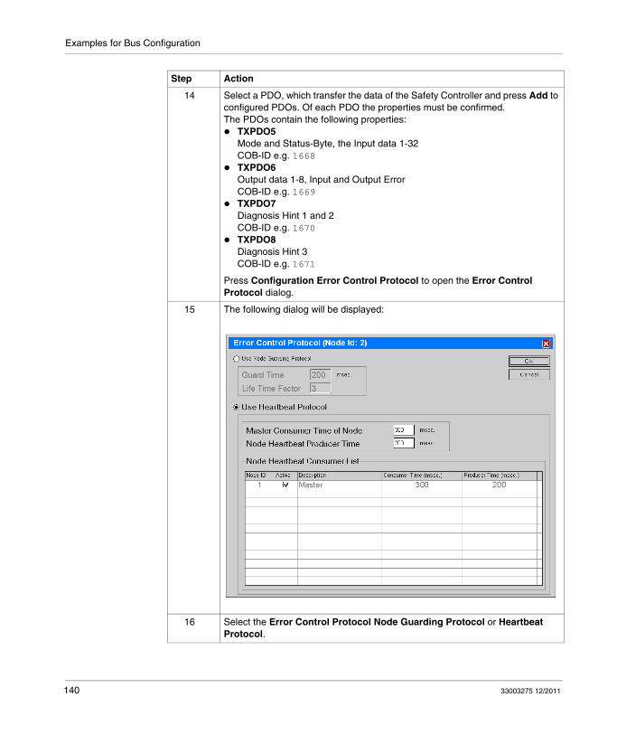
Examples for Bus Configuration
14 Select a PDO, which transfer the data of the Safety Controller and press Add to configured PDOs. Of each PDO the properties must be confirmed.The PDOs contain the following properties:
TXPDO5Mode and Status-Byte, the Input data 1-32COB-ID e.g. 1668TXPDO6Output data 1-8, Input and Output ErrorCOB-ID e.g. 1669TXPDO7Diagnosis Hint 1 and 2COB-ID e.g. 1670TXPDO8Diagnosis Hint 3COB-ID e.g. 1671
Press Configuration Error Control Protocol to open the Error Control Protocol dialog.
15 The following dialog will be displayed:
16 Select the Error Control Protocol Node Guarding Protocol or Heartbeat Protocol.
Step Action
140 33003275 12/2011

Examples for Bus Configuration
17 Select the following parameter:For Node Guarding Protocol
Guard Time200 msecLife Time Factor2
For Heartbeat ProtocolMaster Consumer Time of Node220 msecNode Heartbeat Producer Time200 msecNode Heartbeat Consumer ListActivate the specific master.
18 Press OK to confirm the Error Control Protocol settings.
19 Press OK to confirm the Node Configuration settings.
Step Action
33003275 12/2011 141

Examples for Bus Configuration
Connection of the XPSMC with CANopen and Sycon 2.9
Introduction
This example connects the XPSMC Safety Controller via CANopen to the CANopen master (e.g. Premium TSX with a TSX CPP110 CANopen interface from Schneider Electric). The fieldbus is configured using Sycon 2.9 from Schneider Electric and the controller is be configured using Unity Pro from Schneider Electric.
NOTE: The cables, the connectors and the resistors for CANopen must be in accordance with the CiA DRP 303-1 standard.
Configuration Using Sycon 2.9
The following table shows how to configure CANopen bus using Sycon 2.9:
Step Action
1 Copy the EDS file *.eds into the CANopen EDS directory. The standard installation directory is:c:\programs\Schneider\SyCon\Fieldbus\CANopen\EDSCopy the 3 CANopen pictures (*.dib) into the designated directory, e.g.:\programs\Schneider\SyCON\Fieldbus\CANopen\BMP.You will find this EDS file and the pictures on the supplied CD or you can download it from the Schneider Electric homepage www.schneider-electric.com.
2 Start the Sycon System Configurator.
3 Select the CANopen as fieldbus.
142 33003275 12/2011

Examples for Bus Configuration
4 Choose the CANopen master for the configuration. You will get the dialog box by using Insert → Master.
5 Select the TSX CPP 110 CANopen module and press Add to adopt it to your configuration. Declare the node address and description. The description is limited to 32 characters.
Node ID (address)1DescriptionMaster
Step Action
33003275 12/2011 143

Examples for Bus Configuration
6 Open the bus parameter settings under Settings → Bus Parameter. The following dialog will be displayed:
Step Action
144 33003275 12/2011

Examples for Bus Configuration
7 Configure the following parameters:Master Node ID1Bitrate250 kbit/sMaster stops in case of Node Guard or Heartbeat Error
Disabled
Synchronization Object (SYNC)COB-ID128Communication Cycle Period50 msec.
Heartbeat FunctionEnableMaster Producer Heartbeat Time200 msec.
Enable Global Start Node29 Bit Selection entriesnothing
Press OK to confirm the settings.
Step Action
33003275 12/2011 145

Examples for Bus Configuration
8 After the selection of the CANopen master, insert the CANopen node.Insert the node by using Insert → Node. The following dialog will be displayed:
9 Select the Preventa XPSMC ZC Safety Controller. After the selection press Add >> to adopt it.
10 Configure the following parameters:Node ID2DescriptionXPSMC32ZC
Note: The parameters are examples and can be changed. The maximum length of the description is 32 characters.
Step Action
146 33003275 12/2011

Examples for Bus Configuration
11 Press OK to confirm the settings.The following figure will be displayed:
12 Select Settings → Node Configuration to configure the node settings. The following dialog will be displayed:
Note: Here you can change the Node-ID and Description if necessary.
Step Action
33003275 12/2011 147

Examples for Bus Configuration
13 Select a PDO, which transfer the data of the Safety Controller and press Add to configured PDOs. Of each PDO the properties must be confirmed.The PDOs contain the following properties:
TXPDO5Mode and Status-Byte, the Input data 1-32COB-ID e.g. 1668TXPDO6Output data 1-8, Input and Output ErrorCOB-ID e.g. 1669TXPDO7Diagnosis Hint 1 and 2COB-ID e.g. 1670TXPDO8Diagnosis Hint 3COB-ID e.g. 1671
14 Press PDO Characteristics to open the dialog.
15 The following dialog will be displayed:
Set the Event Timer to 200 ms for each PDO.Note: If the Event Timer is up to 0 and the Transmission Mode is 255 (default settings), the PDO will transmit once at the start up, and when a changing of the data (inputs, outputs, detected errors or diagnostic) occurred, with the exception of Remote Transfer Request. If the Event Timer is up to 0, the cycle data traffic is disabled.
16 Press OK to confirm the settings.
Step Action
148 33003275 12/2011

Examples for Bus Configuration
17 Press Configuration Error Control Protocol to open the Error Control Protocol dialog.
18 The following dialog will be displayed:
19 Select the Error Control Protocol Node Guarding Protocol or Heartbeat Protocol.
20 Select the following parameter:For Node Guarding Protocol
Guard Time200 msecLife Time Factor2
For Heartbeat ProtocolMaster Consumer Time of Node300 msecNode Heartbeat Producer Time200 msecNode Heartbeat Consumer ListActivate the specific master.
21 Press OK to confirm the Error Control Protocol settings.
22 Press OK to confirm the Node Configuration settings.
Step Action
33003275 12/2011 149

Examples for Bus Configuration
Configuration of Unity Pro for CANopen
Introduction
This example show to you to configure Unity Pro for (e.g. Premium TSX with a TSX CPP110 CANopen interface).
Configure Unity Pro
The following table shows how to configure CANopen bus using SYCON 2.9 and Unity Pro.
Step Action
1 Start the Unity Pro.
2 Define the controller configuration within Unity Pro.
3 Choose the CANopen master TSX CPP110 and double click it. You will get the following dialog box (extract):
4 Press Select Database and choose the configuration you have made before with the SYCON tool. See also chapter Connection of the XPSMC with CANopen and Sycon 2.8 (see page 134) or chapter Connection of the XPSMC with CANopen and Sycon 2.9 (see page 142).
5 Press OK to confirm the settings.
6 Create your entire Unity Pro controller program.
7 Generate the program.
8 Transfer the program and configuration into the controller.
9 Run the controller.
150 33003275 12/2011

Examples for Bus Configuration
10 Open the CANopen master by double clicking the module. See also step 3.The following figure will be displayed (extract):
11 Debug the program and configuration by using the Debug register within the TSX CPP 110 dialog box.The CANopen Slaves state shows you the state of the modules. The following colors will be used.
blueWhen a detected error was corrected. It will turn into black when you move the cursor above the text.redWhen a Slave is not working.blackIn other cases.
The Data of CANopen slave dialog shows the values, which will be received from the CANopen master.
12 In case an error is detected on the bus, the Fault register will be active.
13 Press OK to confirm the settings.
Step Action
33003275 12/2011 151

Examples for Bus Configuration
14 Press Configuration Error Control Protocol to open the Error Control Protocol dialog.The following figure (extract) shows that a slave is not running or an error is detected (abstract). In that case the slave is disconnected:
Step Action
152 33003275 12/2011
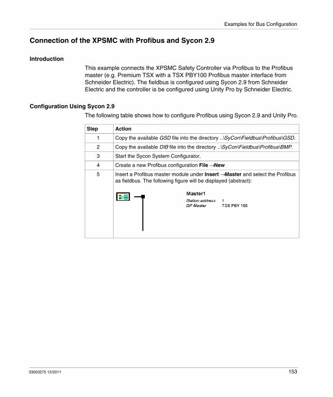
Examples for Bus Configuration
Connection of the XPSMC with Profibus and Sycon 2.9
Introduction
This example connects the XPSMC Safety Controller via Profibus to the Profibus master (e.g. Premium TSX with a TSX PBY100 Profibus master interface from Schneider Electric). The fieldbus is configured using Sycon 2.9 from Schneider Electric and the controller is be configured using Unity Pro by Schneider Electric.
Configuration Using Sycon 2.9
The following table shows how to configure Profibus using Sycon 2.9 and Unity Pro.
Step Action
1 Copy the available GSD file into the directory ..\SyCon\Fieldbus\Profibus\GSD.
2 Copy the available DIB file into the directory ..\SyCon\Fieldbus\Profibus\BMP.
3 Start the Sycon System Configurator.
4 Create a new Profibus configuration File → New
5 Insert a Profibus master module under Insert → Master and select the Profibus as fieldbus. The following figure will be displayed (abstract):
33003275 12/2011 153

Examples for Bus Configuration
6 Insert a Profibus slave module under Insert → Slave. The following dialog will be displayed:
7 Select the XPSMC module and press Add >> to adopt it to your configuration. Declare the node address and description. The description is limited to 32 characters.
Node ID (address)2DescriptionSlave1
Step Action
154 33003275 12/2011

Examples for Bus Configuration
8 Open the slave configuration with a double click on the module. The following dialog will be displayed:
9 Select the XPSMC16ZP or XPSMC32ZP.The following figure shows the available dialog:
10 Press OK to confirm.
Step Action
33003275 12/2011 155

Examples for Bus Configuration
11 Save your configuration under File → Save as.... The following figure will be displayed after the saving:
12 Export your configuration under File → Export → ASCII.
13 Import the configuration into your Profibus master software, e. g. Unity Pro.
Step Action
156 33003275 12/2011
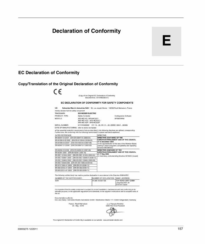
33003275 12/2011
E
XPSMC
Declaration of Conformity
33003275 12/2011
Declaration of Conformity
EC Declaration of Conformity
Copy/Translation of the Original Declaration of Conformity
157

Declaration of Conformity
158 33003275 12/2011

XPSMC
Glossary
33003275 12/2011
Glossary
C
CANStands for controller area network.
The CAN protocol (ISO 11898) for serial bus networks is designed for the intercon-nection of smart devices (from multiple manufacturers) in smart systems for real-time industrial applications. CAN multi-master systems help to ensure high data integrity through the implementation of broadcast messaging and advanced error handling mechanisms. Originally developed for use in automobiles, CAN is now used in a variety of industrial automation control environments.
CANopen ProtocolAn open industry standard protocol used on the internal communication bus. The protocol allows the connection of any standard CANopen device to the island bus.
Configuration ModeFunctional status of the XPSMC in which no valid configuration is available in the controller and in which a configuration can be transferred.
Control OutputAn output providing a test signal, which serves exclusively to power the safety inputs of the XPSMC. As each control output operates with another test signal, cross-connections between safety inputs connected to different control outputs can be detected. External voltage or ground connections can also be detected.
33003275 12/2011 159

Glossary
E
EDMexternal device monitoring
ESPEStands for electro sensible protective equipment.
O
OSSDoutput signal switching device
P
PDOStands for process data object.
In CAN-based networks, PDOs are transmitted as unconfirmed broadcast messages or sent from a producer device to a consumer device. The transmit PDO from the producer device has a specific identifier that corresponds to the receive PDO of the consumer devices.
Profibus DPStands for Profibus decentralized peripheral.
It is an open bus system that uses an electrical network based on a shielded two-wire line or an optical network based on a fiber-optic cable. DP transmission allows for high-speed, cyclic exchange of data between the controller CPU and the distributed I/O devices.
R
Release CircuitSwitches the control voltage for the part of the machine which generates the potentially hazardous movement.
160 33003275 12/2011

Glossary
RUN ModeXPSMC functional status during which the connected circuit members are monitored and the safety outputs are switched.
S
Safety InputShort circuits between inputs and short-circuits of inputs to ground or to external supply can be detected when the control outputs (c1...c8) are used to drive the safety inputs.
Safety OutputRelay or solid-state output activated and monitored by the XPSMC logic unit, which can be used to release safety circuits.
Start InhibitionFollowing power-up, operation is inhibited until the existing input signals are switched off and then re-energized (for example, the safety guard is opened and closed again).
Synchronization TimeMaximum time difference allowed between the appearance of two input signals.
T
TER (Connector for Terminal)8 pin RJ45 connector for the connections of a PC for the configuration or diagnostic (bus system with Modbus protocol) or connections of another Modbus module (controller, terminals, etc....).
33003275 12/2011 161

Glossary
162 33003275 12/2011

XPSMC
Index
33003275 12/2011
CBA
IndexAapplication, 30application example
emergency stop, 129light curtain with muting, 126safety guard with enabling device, 128safety mat, 129two hand control, 129
auto-test, 34
Ccable, 62CANopen, 39, 93
communication port, 94configuration, 134, 142, 150error status, 96master, 135, 143, 150node, 138, 146parameter, 93Sycon 2.8, 134Sycon 2.9, 142Unity Pro, 150wiring, 94
CANopen connection, 41CANopen network and stub length, 97CANopen parameters, 99CANopen/Profibus DP LEDs, 42communication connections TER, 43communication cycle period, 137, 145conformity declaration, 157
33003275 12/2011
connectionCANopen system, 94Modbus system, 46Profibus DP system, 88serial, 44USB, 45
connection diagram, 50connectors, 57
DDIB, 153dimensions, 24
EEDM device, 119EDM devices, 114EDS, 134, 142, 150electrical life of the output contacts, 131elements of the display and system diagnos-tics, 48enabling devices, 114, 121error codes, 59error control protocol, 140, 149error status, 90, 96example
CANopen, 134, 142, 150Profibus, 153Sycon 2.8, 134Sycon 2.9, 142, 153Unity Pro, 150
163

Index
Ffront view of XPSMC, 39function, 31
Ggeneral description
XPSMC16/32, 38GSD, 153
Hheartbeat, 137, 145heartbeat protocol, 140, 149
IIEC 61508
Emergency Shutdown (ESD), 14ESD (Emergency Shutdown), 14Safe state, 14Safety Integrity Level (SIL), 14SIL (Safety Integrity Level), 14
IEC61508Functional Safety, 14
initial operation, 34input circuits, 56Installation, 25
Kkeying, 40
LLED, 48LEDs for CANopen, 96LEDs for Profibus DP, 90LEDs for the operational status, 48length of networks and stubs
CANopen, 97
164
Mmechanical structure, 54Modbus parameters, 86monitoring devices, 114, 115multiple lead connection, 52
Nnetwork length
CANopen, 97node guarding protocol, 140, 149
Oobject dictionary of the XPSMC ZC Safety controller, 101OR function, 122output functional elements, 124
Pparameter
CANopen, 93Profibus DP, 87
power supply, 54Premium PLC communication cards, 64Profibus, 39
configuration, 153Sycon 2.9, 153
Profibus DP, 87communication port, 88error status, 90parameter, 87wiring, 88
Profibus DP connection, 41Profibus DP input data exchange, 91Profibus DP parameters, 92
Rrepresentation, 22
33003275 12/2011

Index
Ssafety relay outputs, 55selector switch, 123settings
CANopen, 93Profibus DP, 87
single lead connection, 52start devices, 114, 120stub length
CANopen, 97Sycon, 134, 142, 153Sycon 2.8, 134Sycon 2.9, 142, 153synchronization, 137, 145
Ttechnical characteristics, 52TER connection, 41, 43terminal, 41, 58terminal connector, 40terminal description, 51terminals, 58timer, 122TSX SCY 11601, 64TSX SCY 21601, 64TSX SCY 21601 specifications, 64
UUnity, 67Unity Pro, 150, 150
XXPSMC models, 20XPSMC• terminals, 52XPSMC16/32, 38
general description, 38
33003275 12/2011
165
Index
166 33003275 12/2011


