PREFACE No : IB29A Authorised Distributor or dealer(s) of the Distributor (‘‘Dealer’’) will be glad to provide you further information or assistance and to handle your future service needs. Let us make this world a safer, healthier and more environment friendly place. This booklet is your guide to the basic operation and maintenance of your new Hero MotoCorp XPULSE 200. Please take time to read it carefully. As with any fine machine, proper care and maintenance are essential for trouble-free operation and optimum performance. We, at Hero MotoCorp, are committed to demonstrate excellence in our environment performance on a continual basis, as an intrinsic element of our corporate philosophy. To achieve this we commit ourselves to continue product innovations to improve environment compatibility and strengthen the green supply chain. We are also using non asbestos brake shoes and engine gaskets which are environment friendly in nature. Thank you for selecting a Hero MotoCorp XPULSE 200. We wish you many miles of continued riding pleasure in the years ahead.
Transcript
PREFACE No : IB29A
Authorised Distributor or dealer(s) of the Distributor (‘‘Dealer’’) will be glad to provide you further information or assistance and to handle your future service needs.
Let us make this world a safer, healthier and more environment friendly place.
This booklet is your guide to the basic operation and maintenance of your new Hero MotoCorp XPULSE 200. Please take time to read it carefully. As with any fine machine, proper care and maintenance are essential for trouble-free operation and optimum performance.
We, at Hero MotoCorp, are committed to demonstrate excellence in our environment performance on a continual basis, as an intrinsic element of our corporate philosophy. To achieve this we commit ourselves to continue product innovations to improve environment compatibility and strengthen the green supply chain. We are also using non asbestos brake shoes and engine gaskets which are environment friendly in nature.
Thank you for selecting a Hero MotoCorp XPULSE 200. We wish you many miles of continued riding pleasure in the years ahead.
Hero MotoCorp Ltd RESERVES THE RIGHT TO MAKE CHANGES IN ITS CONTENTS AT ANY TIME WITHOUT NOTICE AND/OR INCURRING ANY OBLIGATION, WHATSOEVER. NO ONE IS ALLOWED TO REPRODUCE ANY PART OF THIS PUBLICATION WITHOUT OBTAINING PRIOR WRITTEN PERMISSION FROM Hero MotoCorp Ltd.
ALL INFORMATION, ILLUSTRATION, PHOTOGRAPH, DIRECTIONS, SPECIFICATIONS AND OTHER CONTENTS COVERED IN THIS OWNER'S MANUAL ARE BASED ON THE LATEST PRODUCT INFORMATION AVAILABLE AT THE TIME OF ITS PRINTING APPROVAL, AND THE ACCURACY OR CORRECTNESS OF THE SAME IS NOT UNDERTAKEN OR GUARANTEED.
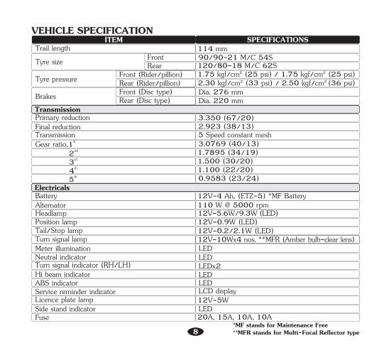
*MF stands for Maintenance Free**MFR stands for Multi-Focal Reflector type8
VEHICLE SPECIFICATION
LED
Tyre size 90/90-21 M/C 54S120/80-18 M/C 62S
FrontRear
Trail length 114 mm
9
Before riding your vehicle
It is a proven fact, helmet significantly reduces the number and severity of head injuries. So always wear a helmet and make sure your pillion rider does the same. We also recommend that you wear eye protection, sturdy boots, gloves and other protective gear.
Take time to learn & practice your vehicle
Make sure that you are physically fit, mentally focused and free of alcohol and drugs. Check that you and your pillion are both wearing an approved vehicle helmet and protective apparel. Instruct your pillion on holding onto the grab rail or your waist, leaning with you in turns, and keeping their feet on the footrest, even when the vehicle is stopped.
Even if you have ridden other vehicles, practice riding in a safe area to become familiar with how this vehicle works and handles, and to become accustomed to the vehicle's size and weight.
IMPORTANT SAFETY INFORMATIONYour vehicle can provide many years of service and pleasure if you take responsibility for your own safety and understand the challenges you can meet on the road.There is much that you can do to protect yourself when you ride. You will find many helpful recommendations through out this manual. Following are a few that we consider most important.Always wear a helmet
VEHICLE SAFETY
Always pay due attention to other vehicles around you, and do not assume that other drivers see you. Be prepared to stop quickly or perform an evasive maneuver.
Ride within your limitsPushing the limits is another major cause of vehicle accidents. Never ride beyond your personal abilities or faster than conditions demand. Remember that fatigue and negligence can significantly reduce your ability to make good judgements and ride safely.
Keep your vehicle in safe condition
Make yourself easily visibleSome drivers do not see vehicles because they are not looking for them. To make yourself more visible, wear bright reflective clothing, position yourself so that others can see you, signal before turning or changing lanes, and use horn which will help others to notice you.
Ride defensively
Do not drink and rideRiding under the influence of alcohol or drugs is dangerous. Alcohol can reduce your ability to respond to changing conditions and reduce the reaction time. Do not drink and ride.
For safe riding, its important to inspect your vehicle before every ride and perform all recommended maintenance. Never exceed load limits, and only use accessories that have been approved by Hero MotoCorp for this vehicle. See (page 11) for more details.
An open-face helmet offers some protection, but a full-face helmet offers more. Always were face shield or goggles to protect your eyes and help your vision.Additional riding gearIn addition to a helmet and eye protection, we also recommend:
• Leather gloves to keep your hands warm and help prevent blisters, cuts, burns, and bruises.
• Sturdy boots with non-slip soles to help protect your feet and ankles.
Helmets and eye protection
• A two wheeler riding suit or jacket for comfort as well as protection. Bright coloured reflective clothing can help make you more noticeable in traffic. Be sure to avoid loose clothes that could get caught on any part of your vehicle.
Your helmet is your most important piece of riding gear because it offers the best protection against head injuries. A helmet should fit your head comfortably and securely. A bright coloured helmet can make you more noticeable in traffic, as can reflective strips.
If you are involved in a crash
PROTECTIVE APPAREL
Personal safety is your first priority. If you or anyone else has been injured, take time to assess the severity of the injuries and whether it is safe to continue riding. Call for emergency assistance if needed. Also follow applicable laws and regulations if another person or vehicle is involved in the crash.If you decide to continue riding, first evaluate the condition of your vehicle. If the engine is still running, turn it off. Inspect for fluid leaks, check the tightness of critical nuts and bolts, and check the handlebar, brake levers, brakes, and wheels. Ride slowly and cautiously. Your vehicle may have suffered damage that is not immediately apparent. Have your vehicle thoroughly checked at a qualified service facility as soon as possible.
Following are suggestions to help you choose proper riding gear.
For your safety, we strongly recommend that you always wear a helmet which should conform as per your country standards, in addition to eye protection, boots, gloves, long pants and a long sleeve shirt or jacket whenever you ride. Take care of loose/ hanging clothes while solo/pillion riding. Although complete protection is not possible, wearing proper gear can reduce the chance of injury when you ride.
• Be sure you and your pillion always wear a helmet, eye protection and other protective apparel when you ride.
• Not wearing a helmet increases the chance of serious injury or death in a crash.
WARNING!!
10
OFF-ROAD SAFETYThis vehicle allows you to enjoy all the excitement of riding it off-road. Forthis, it is necessary to follow some recommendations, which will tie off-road excitement with safety.Protective equipmentEssential for your safety. Make a rule of always wearing them.• Helmet- essential equipment.• Goggles- the greater the visibility, the
better.Choose goggles that do not break or splinter.
• Long- sleeved shirts having fillings in the elbows and shoulders to protect against eventual injuries in the arms.
• Gloves- models with padded hand backs are the most indicated for off-road riding. Choose gloves that fit your hands.
• Adbominal band- it protects internal organs against off-road bumps.
• Nylon trousers with protection in the knees or reinforced jeans. They increase protection. Choose the right size for your proper freedom of motion.
• Boots- they should be made of reinforced leather with thick grooved soles and steel tips. They should also be flexible and fit you properly.
• Waist bag- it is important so you may carry spare parts and those parts that were removed from the vehicle.
LOAD LIMITS AND GUIDELINES
However exceeding the weight limit or carrying an unbalanced load can seriously affect your vehicle's handling, braking and stability. Non accessories, Hero MotoCorpmodifications, and poor maintenance can reduce your safety margin.
How much weight you put on your vehicle, and how you load it, are important to your safety. Anytime you ride with a pillion or cargo you should be aware of the following information.
Loading
Preparing the vehicleFor off-road practice, it is essential that your vehicle is in perfect mechanical condition. The front brake lever, clutch lever and turn signal brackets should be loosened in order to rotate in case of falling down, preventing breakage. They should be loosened to turn on the handlebars only with a slight force. Under most adverse conditions, the rear view mirrors and turn signals should be removed.
Your vehicle has been designed to carry you, one pillion and limited amount of cargo. When you add cargo or carry a passenger, you may feel some difference during acceleration and braking. But so long as you keep your vehicle well maintained, with good tyres and brakes, you can safely carry loads within the limits and guidelines.
11
12
WARNING!!• Overloading or improper loading can cause
a crash and you can be seriously injured.• Follow all load limits and other loading
Improperly loading your vehicle can affect its stability and handling. Even if your vehicle is properly loaded, you should ride at reduced speeds whenever carrying cargo.
• Keep cargo and accessory weight low and close to the center of the vehicle. Load weight equally on both sides to minimize imbalance. As weight is located further from the vehicle’s center of gravity, handling is proportionally affected.
• Adjust tyre pressure (page 64) to suit load weight and riding conditions.
Follow these guidelines whenever you carry a pillion or cargo:
• Vehicle handling and stability can be adversely affected by loose cargo. Recheck cargo security and accessory mounts frequently.
• Do not attach large or heavy items to the handlebars, front fork or fender. Unstable handling or slow steering response may result.
Your vehicle is primarily intended for transporting you and a pillion. If you wish to carry cargo, check with your Authorised Distributor/Dealer for advice and be sure to read the information regarding accessories on (page 13).
This vehicle is designed to carry the rider (1) and one pillion (2). The overall weight should be distributed in four points (A, B, C, and D) and should never exceed the maximum load capacity of 130 kg. This will assure higher stability, better drivability and more comfort.
Load limits and weight distribution
(1)+(2)=130 kg {where,1=A+B & 2=C+D}
C A
D B
2 1
Damages caused by excessive load will not be covered under Hero MotoCorp warranty policy. If you are not sure about how to calculate the load weight that can be accommodated to your vehicle without causing overload and structural damages, see your Authorised Distributor/Dealer.
13
ACCESSORIES & MODIFICATIONSModifying your vehicle or using non-HeroMotoCorp accessories can make your vehicle unsafe. Before you consider making any modifications or adding an accessory, be sure to read the following information.
operation. Such changes could seriously impair your vehicle's handling, stability and braking, making it unsafe to ride. Removing or modifying your lamps, mufflers, emission control system or other equipment can also make your vehicle illegal.
• Enter your name, address and phone number in this Owner's Manual and keep it in your vehicle at all times. Many times stolen vehicles are identified by information in the Owner's Manuals that are still with them.
• Never park your vehicle in an isolated area. Park as far as possible in a designated area.
ANTI-THEFT TIPS• Always lock the steering and never leave the
key in the ignition switch. This sounds simple but people do forgets.
• Be sure the registration information for your vehicle is accurate and correct.
• Park your vehicle in a locked garage whenever possible.
• Use an additional anti-theft device of good quality.
• Do not pull a trailer or sidecar with your vehicle. This vehicle was not designed for these attachments, and their use can seriously impair your vehicle's handling.
Accessories• Make sure that the accessory does not
obscure any lamps, reduce ground clearance, limit suspension travel or steering travel, affect your riding position or interfere with operating any controls.
• Be sure electrical equipment does not exceed the 's electrical system vehiclecapacity (page 8). A blown fuse can cause a loss of lights.
ModificationsWe strongly advise you not to remove any original equipment or modify your vehicle in any way that would change its design or
• Follow all instructions in this owner's manual regarding accessories and modifications.
• Improper accessories or modifications can cause a crash in which you can be seriously hurt or killed.
WARNING!!
14
SAFE RIDING TIPS
• During night time vehicle, dip headlamps of your for oncoming traffic, or when following another vehicle.
• Take care of loose/hanging clothes while solo/pillion riding.
• For stopping vehicle, use both brakes simultaneously, keeping throttle in the close position.
• Ride defensively and at a steady speed (between 40-50 km/hr).
• To make yourself more visible, wear bright reflective clothing that fits well.
• Before riding make sure that engine stop switch is in “ON” ( ) position.
• vehicleGet your serviced regularly by the Authorised Distributor/Dealer.
• While riding, sit in a comfortable position with your legs close to fuel tank.
• Always wear a helmet with chinstrap securely fastened and insist on a helmet for your pillion rider. Helmet should conform as per safety standards applicable in your country.
Do's:
• Give way to others on the road and signal before you make a turn.
• Keep checking the ABS indicator. At any point if indicator remains on, then ABS is not working (page 30).
• Keep checking speedometer. In case of ABS malfunction, speed display may go to zero.
• It is suggested to go through the do’s & dont’s of ABS (page 38) and practice your ABS vehicle initially in low-traffic condition unless you are thoroughly familiar with your vehicle and its controls.
• Never ride under the influence of alcohol or drugs.
• Do not attempt to apply the front brake lever intermittently for ABS vehicle.
• Do not attach large or heavy items to the handlebars, front forks, or fenders.
• Never touch any part of the hot exhaust system like muffler.
• Do not switch off the engine stop switch while riding the vehicle (page 30).
• Do not panic by mechanical noises or slight pedal pulses while applying the brake in vehicle. These conditions are normal and indicates that ABS is working.
• Navigation system assists you to reach your destination, don't be distracted while driving. Drive safely and always obey traffic rules.
• Never use cell phone while riding the vehicle.• Avoid sudden acceleration, braking and turning of
your vehicle.• Never shift gears without disengaging the clutch and
closing the throttle.
Don'ts
• Do not apply the hard braking in wet or rainy conditions.
• Concentrate on the road and avoid talking to the pillion rider or others on the road.
• Do not cross the continuous white/yellow line in the center of the road, while overtaking.
• Do not litter the road.
• Never take your hands off the steering handle while riding.
• Noise pollution: Noise beyond a certain decibel is pollution. Whether it is from horns or defective mufflers, excessive noise will cause headaches and discomfort.
The following tips shall ensure a healthy vehicle, healthy environment, and a healthy you.
• Healthy engine: The engine is the lifeline of every vehicle. To keep it healthy, it should be tuned regularly, which will also help reduce pollution and improve vehicle performance & fuel efficiency.
• Regular servicing: Get your vehicle serviced at an Authorised Distributor/Dealer, as per the service schedule, for an optimum performance and keep the emission level under check.
• Genuine spares: Always insist on Hero MotoCorp genuine parts as spurious or incompatible spares and accessories can upset or deteriorate your vehicle’s running condition.
• Genuine engine oil: Hero 4T Plus SAE 10W 30 SL grade (JASO MA2) engine oil recommended by Hero MotoCorp and make sure you change it every 6000 km. (with top up every 3000 kilometres) to keep the engine fit and environment healthy.
• Fuel saving & reduce pollution: Switch "OFF" the engine while waiting at traffic signal points to save fuel and reduce pollution, if the waiting period is long.
TIPS FOR HEALTHY ENVIRONMENT
15
16
The LCD panel illuminates & initial display of multi function digital segments are displayed. The tachometer segment and the fuel gauge segment will swing to the maximum scale once and back to its normal position. The engine can be started. Turn signal lamp, horn, tail/stop lamp, fuel gauge, & pass lamp, position lampneutral indicator will be functional.
Key cannot be removed.
Engine cannot be started and no electrical system will be functional. Key can be removed.
Steering can be locked. Key can be removed.
“OFF” ( ) Position/Lock Open
“LOCK” Position
“ON” ( )Position
“LOCK”
“ON” ( )
“OFF” ( )
5. “ON” ( ) position
3. “OFF” ( ) position
1. Ignition switch
4. Steering lock position
2. Ignition key
Key Position Function Key Removal
PARTS FUNCTIONIGNITION SWITCH
2
4
35
1
Sl. No. Description Function
1
6Anti-lock braking system (ABS) indicator
TachometerShows engine revolution per minute. The tachometer digital segments will swing to maximum scale on the meter console once the ignition switch is turned “ON” .
High beam indicator Light glows when headlamp is in high beam.4Neutral indicator Light glows when vehicle is in neutral.
Turn signal indicator(R) Flashes when right turn signal switch is operated.7
INSTRUMENTS AND INDICATORSThe indicators are in the speedometer panel above the headlamp. The functions are as below.
17
This indicator normally comes on for approx 1.8 seconds when the ignition switch is turned “ON” ( ) & then keeps blinking until the vehicle attains speed of 5 km/h. If there is a problem with the anti-lock brake system, ABS indicator turns on (page 30).
5
3 Turn signal indicator(L) Flashes when left turn signal switch is operated.
x 000�I
FFF
EEEkm/h
RPM
Gear
ODOODOODO km
000
III
222333 444 555 666 777 888 999 IOIOIO IIIIII
241.6 kmto go
Serv
64 75
9
1 32
14131516
8
12
Side stand indicator Light glows when the vehicle is parked on the side stand.2
Mode button Switches display between odometer, tripmeter-1 & 2, clock, Eco mode & Bluetooth connectivity. 8
Service reminder indicator Displays when the next service is due (page 22).
11
10 Next service distanceIndicates how many kilometers are left before the next service is due. It appears for few seconds when the ignition switch is turned “ON” ( ) (page 22).
Gear indicator Displays the selected gear while riding (page 23).16
Indicates approximate fuel available in the form ofdigital segments. The digital segments (11a) will swing tomaximum scale on the meter console once the ignitionswitch is turned “ON” ( ). If all the segments (11a) aredisplayed it means fuel quantity in the fuel tank is 13.0litres. If only one segment is displayed and blinks, thisindicates the fuel quantity is low and the fuel tank shouldbe refilled as soon as possible.
9 Set button To adjust clock, date & tripmeter. When long pressed resets tripmeter to zero.
(a) Digital clock
• To set the hour, press set button (2) until the desired hour is displayed.
• The time advances fast when the button is pressed and held.
• The time is advanced by 1 hour each time the button is pressed.
• Press the mode button (3). The minutes display starts blinking.
LCD PANEL
• The time advances by 1 minute, each time the button is pressed.
• To set the minute press set utton ( ) until b 2the desired minute is displayed. The minute display will return to is "60" "00" afterreached without affecting the hour display.
19
(1) Digital clock (2) Set button (3) Mode button
(2) Set button
(3) Mode button
• Turn the ignition switch "ON" ( ).
Digital clock (1) shows hour and minute. To adjust the time, proceed as follows :
• Press and hold set button (2) and mode button (3) simultaneously for more than 2 seconds. The clock will be set in the adjust mode with the hour's digit display blinking.
12:412
3
1
12:41
241.6 km
Avg45.1 km/h
Time1h 06m
Trip 1
30 Aug
x 000�I
FFF
EEEkm/h
RPM
Gear
ODOODOODO km
000
III
222333 444 555 666 777 888 999 IOIOIO IIIIII
14:41
12:41
241.6 km
Avg45.1 km/h
Time1h 06m
Trip 1
30 Aug
x 000�I
FFF
EEEkm/h
RPM
Gear
ODOODOODO km
000
III
222333 444 555 666 777 888 999 IOIOIO IIIIII
14:41
2
14:41
3x 000�I
FFF
EEEkm/h
RPM
Gear
ODOODOODO km
000
III
222333 444 555 666 777 888 999 IOIOIO IIIIII
241.6 km
Avg45.1 km/h
Time1h 06m
Trip 1
30 Aug
• To end the adjustment press the mode button (2) until clock display stops blinking.
If the tripmeter exceeds "999.9" km it will return to "0.0" km automatically.
(b) Odometer/Tripmeter
Push the mode button (3) to select “Trip-1” and “Trip-2”. “Trip-1” and “Trip-2” can be displayed upto " km.999.9"
The tripmeter shows distance travelled since trip meter was reset last time. There are two tripmeters, “Trip-1” and “Trip-2”.
The odometer (1) shows accumulated distance travelled.
• The time advances fast when the button is pressed and held.
20
When tripmeter is selected, long press (more than 2 seconds) the set button to reset tripmeter to zero. The odometer can be displayed from "0 to 99999" km.
Trip meter displays following parameters:
• Trip time: time taken to complete a trip.
• Avg speed: average speed at which vehicle completes a trip
• Distance: distance covered in a trip.
• Date: it shows the current date. 241.6 km
Avg45.1 km/h
Time1h 06m
Trip 1
30 Aug
x 000�I
FFF
EEEkm/h
RPM
Gear
ODOODOODO km
000
III
222333 444 555 666 777 888 999 IOIOIO IIIIII
14:48
14:41
(2) Set button2
(1) Odometer (2) Tripmeter(3) Mode button (4) Set button(5) Date
x 000�I
FFF
EEEkm/h
RPM
Gear
ODOODOODO km
000
III
222333 444 555 666 777 888 999 IOIOIO IIIIII
241.6 km
Avg45.1 km/h
Time1h 06m
Trip 1
30 Aug
5
4 241.6 km
Avg45.1 km/h
Time1h 06m
Trip 1
130 Aug
32
To update the date proceed as follows :
• Press and hold set button (4) and mode button (3) simultaneously for more than 2 seconds. The clock display will start blinking (page 19).
• Keep pressing and releasing mode button (3) until date display (5) starts blinking.
• Turn the ignition switch "ON" ( ).
NOTENOTEThe clock will reset to if the battery is “1:00”disconnected.
(3) Mode button (5) Date display
x 000�I
FFF
EEEkm/h
RPM
Gear
ODOODOODO km
000
III
222333 444 555 666 777 888 999 IOIOIO IIIIII
241.6 km
Avg45.1 km/h
Time1h 06m
Trip 1
30 Aug
30 Aug
3
5Year 2021
• Now to set year, press set button (4) until the desired year is displayed.
• To set month, press the mode button (3) to switch from year to month display. Now press the set button (4) until the desired month is displayed.
Year 2021
(4) Set button (5) Date display
x 000�I
FFF
EEEkm/h
RPM
Gear
ODOODOODO km
000
III
222333 444 555 666 777 888 999 IOIOIO IIIIII
241.6 km
Avg45.1 km/h
Time1h 06m
Trip 1
Year 2021
Year 20185 4
(3) Mode button (4) Set button(5) Date display
01 Janx 000�I
FFF
EEEkm/h
RPM
Gear
ODOODOODO km
000
III
222333 444 555 666 777 888 999 IOIOIO IIIIII
241.6 km
Avg45.1 km/h
Time1h 06m
Trip 1
01 Jan
01 Feb5
3
4
x 000�I
FFF
EEEkm/h
RPM
Gear
ODOODOODO km
000
III
222333 444 555 666 777 888 999 IOIOIO IIIIII
241.6 km
Avg45.1 km/h
Time1h 06m
Trip 1
01 Feb
01 Feb
3
45
02 Feb
(3) Mode button (4) Set button(5) Date display
• To set day, press the mode button (3) to switch from month to day display. Now press the set button (4) until the desired day is displayed.
• To end the adjustment press the mode button until date display stops blinking.
21
22
NOTENOTEAfter getting the vehicle serviced, make sure that the Service Reminder Indicator has been reset.
FEATURES(a) ECO modeECO mode assists the rider to achieve optimum fuel efficiency.Press the ode button (1) unm til ECO mode (2) is displayed.
(1) Service reminder indicator(2) Next service distance.
x 000�I
FFF
EEEkm/h
RPM
Gear
ODOODOODO km
000
III
222333 444 555 666 777 888 999 IOIOIO IIIIII
241.6 kmto go
Serv
241.6 kmto go
Serv
21
M
It displays following riding instructions :• Shift up indicator: it recommends for
shifting to high gear.
Eco
(1) Mode button (2) Eco mode
x 000�I
FFF
EEEkm/h
RPM
Gear
ODOODOODO km
000
III
222333 444 555 666 777 888 999 IOIOIO IIIIII
Eco
2
1
(c) Service reminder indicatorThe service reminder indicator (1) is to indicate the user to bring the vehicle to an Authorised Distributor/Dealer for service. The indicator shall start blinking when the vehicle covers kilometers as specified in the maintenance schedule. The indicator will keep on blinking throughout the kilometer interval for a particular service and will stay ‘‘ON’’ thereafter.Meter console also displays the next service distance (2). It indicates how many kilometers are left before the next service is due. It appears for few seconds when the ignition switch is turned “ON” ( ).The service reminder indicator “ ” can only be reset at an Authorised Distributor/Dealer.
23
• Shift down indicator: it recommends for shifting to low gear.
Gear indicator (1) indicates current gear condition of your vehicle in which it is running.
(b) Gear indicator
x 000�I
FFF
EEEkm/h
RPM
Gear
ODOODOODO km
000
III
222333 444 555 666 777 888 999 IOIOIO IIIIII
241.6 kmto go
Serv
Gear
1(1) Gear indicator
NOTENOTE
• Gear indicator displays “-” when it delays in displaying the gear indication or when you change gears in vehicle static condition (vehicle is in main stand and ignition switch is in "ON" position).
• Gear indicator displays “0” when your vehicle is in neutral.
(3) Shift up indicator
x 000�I
FFF
EEEkm/h
RPM
Gear
ODOODOODO km
000
III
222333 444 555 666 777 888 999 IOIOIO IIIIII
Eco
3
Eco
Eco
x 000�I
FFF
EEEkm/h
RPM
Gear
ODOODOODO km
000
III
222333 444 555 666 777 888 999 IOIOIO IIIIII
Eco
4(4) Shift down indicator
NOTENOTE
It is recommended to ride your vehicle as per road and traffic conditions.
ECO mode assists the rider to achieve optimum fuel efficiency based on your vehicle's engine performance.
Application:Hero navigation application (1) is available in the google play store (for androids) or App Store (for iOS), which can be installed in your device to access bluetooth, incoming calls alerts, mobile low battery alert, and navigation features.
(c) Hero ride guide/Navigation
24
c. Contactsd. Make & manage phone callse. Phone call logs on your device
a. Device’s location if GPS is not enabled in your device
b. Photos, media, files
• Now select “GET STARTED” (2) to proceed.
• Application also asks you to accept (3) the terms and conditions to proceed.
Your vehicle is equipped with bluetooth connectivity feature by which you can pair your smartphone with the meter console of your XPULSE 200 vehicle through Hero navigation application.
Bluetooth:
To connect your device proceed as follows:• Turn the ignition switch “ON”.• Open hero navigation application (1) on
your smartphone.
• For first time pairing, allow the application to access:
1(1) Hero navigation application
ALLOW
c d e
ALLOW
a b
NOTENOTE
• Application needs GPS signal, internet and bluetooth connectivity to perform the desired navigation functionality.
• Compatibility and performance of hero ride guide application may very based on your device and software version.
25
• Now login your app using facebook or google (4) account and get started.
• Allow (5) the application to turn on bluetooth if it is not enabled in your device.
• The application searches for a while and displays all nearby devices. Select the device with your name (6).
• Update your name (7) (if required) and select either save and connect (8) or connect (9) to proceed.
(2) Get started (3) Accept terms and condition
(6) Select your device
Xyz
6
Xyz
SAVE AND CONNECT CONNECT
(7) Select your device(8) Save and connect(9) Connect
87 9
32
4(4) Log in through Facebook or Google (5) Turn on bluetooth
HeroNav is asking to turn onBluetooth
DENY ALLOW
5
26
• After processing for a while, meter console will display the direction (5), distance for next move (7) and estimated time of arrival (ETA) (6). Estimated time of arrival will be displayed in "am"or "pm". Hero navigation app and meter console of your vehicle will display step by step navigation guidance/direction through navigation signs (page 74).
• On pairing, meter console displays “connected” (10) below bluetooth symbol in bluetooth mode (11).
(1) Current location (2) Choose destination (3) Start ride
(10) Bluetooth connected (11) Bluetooth mode
x 000�I
FFF
EEEkm/h
RPM
Gear
ODOODOODO km
000
III
222333 444 555 666 777 888 999 IOIOIO IIIIII
Pair
Connected
Pair
Connected
10
• If any error occurs during the course of pairing process, then meter console will display “Not found” (12) below bluetooth symbol. Repeat the above steps and keep your smartphone closer to the vehicle to reconnect.
Navigation:To use navigation feature proceed as follows:• Connect your vehicle with your hero ride
guide/navigation application via bluetooth (page 24).
• After successful connection, the application and meter console display will automatically switch to navigation mode (4). It will also update your current location (1) through GPS system.
• Now choose your destination (2) through the application and select “start ride” (3).
x 000�I
FFF
EEEkm/h
RPM
Gear
ODOODOODO km
000
III
222333 444 555 666 777 888 999 IOIOIO IIIIII
Pair
NOT FOUND
Pair
NOT FOUND
11
12
11
(11) Bluetooth mode (12) Not found
M
S
3
1
XYZ.....
ABC.... ABC.....
2
XYZ.....
START RIDESTART RIDE
ABCXYZ
27
(4) Navigation mode (5) Direction (6) ETA(7) Distance for next move (8) No signal
x 000�I
FFF
EEEkm/h
RPM
Gear
ODOODOODO km
000
III
222333 444 555 666 777 888 999 IOIOIO IIIIII
Nav
1.2 km
12h : 20min
Nav
1.2 km
7 : 32 pm
Autopairing:Your vehicle is equipped with autopairing feature by which if you turn ''OFF'' vehicle's ignition switch after successful pairing with hero navigation application, it will reconnect automatically once ignition switch is turned ''ON''.
NOTENOTEAlways keep your smartphone close to your vehicle during the course of pairing, autopairing and navigation.
NOTENOTEAt any point, if Navigation system loses signal, then it displays "No Signal" (8) on meter console when vehicle is in navigation mode.
1.2 km
Nav
7 : 32 pm
1.2 km
Nav
7 : 32 pm
No Signal
456 8
7
Navigation system assists you to reach your destination, don't be distracted while driving. Drive safely and always obey traffic rules.
WARNING!!
Incoming call alert:If your smartphone is paired with the meterconsole of your vehicle via bluetooth (page 24), then you will get all the incoming calls alerts on the meter console. It will display the name of the caller if it is stored in your compatible smartphone. For example: If caller’s number is stored in your compatible smartphone by name of Vijay, then your meter console will display Vijay calling (1).
(1) Incoming call alert by name
M
S
Vijay
Calling
Callx 000�I
FFF
EEEkm/h
RPM
Gear
ODOODOODO km
000
III
222333 444 555 666 777 888 999 IOIOIO IIIIII
M
S
Vijay
Calling......
Call
If the number is not saved in your device by name or your device is an iOS, then it will display “unknown calling” (2).
1
28
Steering lock is with the ignition switch, turn the key (1) to “OFF” ( ) position & turn the handle bar towards left or right & push the key downwards & turn towards "Lock" position. After locking take out the key.
(d) Steering lock
(1) Ignition key
While installing the rider footrest rubbers, the projections (3) of the rider footrest rubbers must be attached to the rider footrest properly.
(e) Rider footrest The rubbers (1) of the rider footrest (2) (both side) are detachable and can be detached for “OFF-ROAD” riding only {refer off-road safety guide line (page 11)}.
(1) Rubbers (2) Rider footrest (3) Projections
A symbol of low battery alert (1) appears for few seconds on the meter console if the battery of your paired smartphone is too low.
Low battery alert:(2) Incoming call alert by unknown number
M
S
Unknown
Calling
Callx 000�I
FFF
EEEkm/h
RPM
Gear
ODOODOODO km
000
III
222333 444 555 666 777 888 999 IOIOIO IIIIII
M
S
2
Unknown
Calling......
Call
(1) Low battery alert
x 000�I
FFF
EEEkm/h
RPM
Gear
ODOODOODO km
000
III
222333 444 555 666 777 888 999 IOIOIO IIIIII
Alert !
Low Batt
Alert !
Low Batt
1
1
1
3
2
29
Left handlebar controls1. Headlamp dimmer switch/Pass
switch
HANDLEBAR SWITCHES CONTROL
Shift the turn signal switch (2) sideways for right/left indications and leave it to come back to its normal position on its own.
2. Turn signal lamp switch ( )
Press the pass switch to “PASS” position to operate the pass lamp.
The headlamp operates only when the engine is running.Press the switch (1) upwards for high beam “ ” downwards for low beam “ ”.
IMPORTANT: To switch “OFF” the turn signal after completing the turn, gently push the switch inside.
4. Bystarter knob ( )
NOTEDo not accelerate during starting when the bystarter is on.
To apply bystarter, pull the knob (4) towards the rider.
There is a clutch switch (5) provided for the safety of the rider. The vehicle cannot be started by electric starter switch until the clutch lever is operated when the vehicle is engaged in gear.
5. Clutch switch
3. Horn switch ( )Press the switch to operate the horn (3).
(1) Headlamp dimmer switch/Pass switch
(4) Bystarter knob(2) Turn signal switch (3) Horn switch
(5) Clutch switch
5
1
3
4
2
1. Electric starter switch ( )Right handlebar controls
Ensure starter switch ( ) is operated when the 1vehicle transmission is in neutral. If the vehicle is engaged in gear, press the clutch lever before operating the starter switch. Release starter switch after the engine has started.
(1) Electric starter switch
1
2
WARNING!!While riding the vehicle in normal condition, do not switch off the “Engine stop switch” to avoid any damage (Wheel locking leading to accident, part damage, battery discharge etc.).
(2) Engine stop switch
Never hold electric starter switch continuously more than 5 seconds as continuous cranking of engine will discharge the battery.
CAUTION!!
The engine stop switch (2) is provided next to throttle grip. The switch has two positions. In “ON” ( )position, engine will operate and in “OFF” ( ) position, engine will not operate. The prime function of switch is to stop the engine during emergency (Vehicle tip over, throttle cable stuck etc.). The switch should normally remain in “ON” ( ) position. During
2. Engine stop switch
emergency, put the switch to “OFF” ( ) position.
At any point if ABS indicator remains “ON” then ABS is not working, but the brakes still work normally. Reduce your vehicle speed and visit your Authorised Distributor/Dealer.
When the system functions normally indicator goes “OFF” ( ) once vehicle speed exceeds 5 km/h.
ABS INDICATORThe ABS indicator (1) on speedometer come “ON” for approx 1.8 seconds when the ignition switch is turned “ON” ( ) & then keeps blinking until the vehicle attains a speed of 5 km/h.
30
For the safety of the customer a side stand indicator (1) is provided.
SIDE STAND INDICATOR/SWITCH(1) ABS indicator
1
(1) Side stand indicatorA side stand switch (2) is provided in the side stand, when the side stand is down (Ignition Switch “ON” ( )), the switch enables the side stand indicator lamp to glow on the speedometer panel.
• If the side stand indicator (1) does not operate as described in above steps, please visit your Authorised Distributor/Dealer.
• Check the side stand for proper function and the spring (3) for damage or loss of tension and the side stand assembly for free movement.
• Check whether the side stand indicator (1) glows when the side stand is down.
• While the vehicle is removed from side stand, the side stand indicator (1) should not glow.
(2) Side stand switch (3) Side stand spring
Ensure that adequate care should be taken while cleaning the side stand switch.
CAUTION!!
FUEL TANKFuel tank capacity is 13.0 litres including usable reserve supply of 2.0 litres (Usable).
1
3
2
31
• To unlock fuel tank cap, lift the key hole cover (1), insert key (2) turn it clockwise and lift open the cap (3).
(1) Key hole cover (2) Ignition key
2
1
Front
45
(4) Filler neck (5) Fuel
(3) Fuel tank cap
3
• Do not overfill the tank. There should be no fuel in filler neck (4). Fill the tank with fuel (5) as shown.
• To lock fuel tank cap, close the cap back on the opening and press gently. The key springs back to the normal position and cap gets locked.
• Remove the key and put back the keyhole cover.
CAUTION!!Do not park the vehicle under direct sunlight as it causes evaporation of petrol due to heat and deterioration of paint gloss due to ultra violet rays.
WARNING!!Petrol is extremely flammable and is explosive under certain conditions. Refill in a well ventilated area with the engine stopped. Do not smoke or allow flames or sparks in the area where the vehicle is refilled or where petrol is stored.
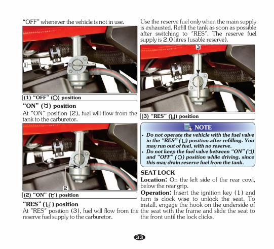
FUEL VALVEThe three way fuel valve is on the left side of the carburetor.“OFF” ( ) positionAt “OFF” position (1), fuel cannot flow fromthe tank to the carburetor. Turn the valve
32
(1) “OFF” ( ) position
Use the reserve fuel only when the main supply is exhausted. Refill the tank as soon as possible after switching to "RES". The reserve fuel supply is 2.0 litres (usable reserve).
“RES” ( ) positionAt "RES" position (3), fuel will flow from the reserve fuel supply to the carburetor.
(3) “RES” ( ) position
3
“ON” ( ) positionAt “ON” position (2), fuel will flow from the tank to the carburetor.
(2) “ON” ( ) position
NOTE• Do not operate the vehicle with the fuel valve
in the “RES” ( ) position after refilling. You may run out of fuel, with no reserve.
• Do not keep the fuel valve between “ON” ( ) and “OFF” ( ) position while driving, since this may drain reserve fuel from the tank.
Location: On the left side of the rear cowl, below the rear grip.
SEAT LOCK
Operation: Insert the ignition key (1) and turn is clock wise to unlock the seat. To install, engage the hook on the underside of the seat with the frame and slide the seat to the front until the lock clicks.
“OFF” whenever the vehicle is not in use.
2
1
33
USB CHARGERA USB charger (1) with a cap (2) located inside the USB device compartment (3) is provided in your vehicle under the seat to charge your mobile phone safely while riding.
To connect a mobile phone charger, first remove the cap from the USB charger and then plug in the charger cable to it.
Use of non-standard USB cable may cause damage to the mobile phones. Hero MotoCorp will not be responsible for damages caused due to use of non standard USB cable.
2
(1) USB charger (2) Cap(3) USB device compartment
• Always place the device in a soft clean cloth/towel to avoid any damage due to road shocks while riding.
• This port is for charging compatible USB devices.
• Charge your device only when the engine is operational/while riding. Charging the USB device when the engine is “OFF” would lead to early discharge of battery.
• Multiple charging of USB devices have to be avoided, simultaneous charging may lead to slow or no charging.
• Do not leave the USB device and USB cable in the USB device compartment when the vehicle is parked.
CAUTION!!
• Any personal belongings have to be removed before water washing to avoid damage.
• Do not apply any soap solution, oil or grease inside the USB charger.
• Always keep the USB port cap closed after use to prevent dust or water entry during rains/water wash.
• Do not direct water jet towards the port even with cap closed to avoid any short circuit. Always dry the area using a dry cloth or moisture free compressed air before use.
NOTE
1
(1) Seat lock1
3
34
• Front brake-Check for correct brake fluid level in master cylinder/ (page reservoir58).
• Rear brake-Check for correct brake fluid level in the reservoir (page 59).
Clean your vehicle regularly. It protects the surface finish. Avoid cleaning with products that are not specifically designed for vehicle surfaces.
• Fuel level-Ensure sufficient fuel is available in the fuel tank for your journey (page 31). Check for leaks.
PRE- RIDE INSPECTIONYou should conduct pre ride inspection before riding the vehicle to enhance riding comfort and safety.
• ABS indicator-Check ABS indicator for proper functioning of ABS (page 30).
• Engine oil level-Check and top up engine oil if required (page 46). Check for leaks.
• Tyres-Check condition and pressure (page 64).
Inspect your vehicle every day before you start the engine. The items listed here will only take a few minutes, and in the long run they can save time, expense, and possibly your life. Please follow the tips as given below:
• Air suction valve-M ake sure all tube connections are secured properly (page 70).
• Rear view mirror-Ensure that the rear view mirror gives a good rear view when you are sitting on the vehicle.
• Clutch-Check for smooth operation. Adjust free play if necessary (page 52).
• Throttle-Check for smooth opening and closing in all steering positions .(page 53)
• Fitting & Fasteners-Check & tighten if necessary.
• Steering-Check for smooth action and for easy maneuverability.
• Lamps & Horn- Check that headlamp,position lamps, tail/stop lamp, turn signal lamps, indicators and horn function properly.
• Side stand indicator-Make sure that the side stand is up. If it is in down position the side stand indicator will glow on (page 31)the speedometer panel.
• Drive chain-Check condition and slackness Lubricate if(page 54). necessary.
• Engine stop switch-Check for proper function (page 30).
35
WARNING!!Never run the engine in a closed area, the exhaust contains poisonous gases.
STARTING THE ENGINE1
Turn the ignition switch “ON” ( ).
3
Select neutral position & check N indicator glows on instrument cluster with ignition “ON”( ).
2
( ).Turn the fuel valve “ON”
4
Make sure that the engine stop switch is at “ON” ( ) position.
NOTE• To start the engine in any gear position using the electric starter, press the clutch lever and
push the starter switch.• Kick starting will not be possible when the transmission gears are engaged unless you press
clutch lever. Press the clutch lever or shift the transmission to neutral before kick starting.• Never attempt to kick start while vehicle is moving forward or backward. This may lead to
damage to the product and is not safe as well.
Press the starter switch to start the vehicle.(Alternatively, kick start pedal can be used for starting).
6
Pull the bystarter knob outwards to “ON” position as indicated (Use bystarter during cold conditions).
Push the bystarter knob inwards to “OFF”, position as indicated, after the engine gets sufficiently warmed up to have a stable throttle response.
5 7
36
• While the engine is idling, press the clutch lever and depress the gearshift pedal
stdownwards using the toe to shift into 1 gear.
Help assure your vehicle's future reliability and performance by paying extra attention to how you ride during the first 500 km.
• This sequence is repeated progressively to rd th thshift to 3 , 4 and 5 gear.
Running in
During this period, avoid full-throttle starts and rapid acceleration.
• When the vehicle attains a moderate speed, close the throttle, press the clutch lever and
nd shift to 2 gear by placing the toe on the underside of gear pedal and lift upwards.
Flooded engine
• After the engine has been warmed up, the vehicle is ready for riding.
• Slowly release the clutch lever and at the same time, gradually increase engine speed by opening the throttle. Coordination of the throttle and clutch lever will assure a smooth positive start.
RIDING
If the engine fails to start after repeated attempts, it may be flooded with excess fuel. To clear a flooded engine, turn the ignition switch “OFF” ( ) and push the bystarter knob to “OFF”. Close the throttle fully and crank the engine several times with the kick starter. Turn the ignition switch “ON” ( ) and start the engine without using bystarter.
CAUTION!!Do not shift gears without operation of clutch and without closing the throttle otherwise this would lead to damage of gears.
BRAKINGAnti-lock braking system (ABS)This model is equipped with Anti-lock braking system (ABS). ABS enhances active safety by helping to prevent the wheels from locking under braking. ABS is designed to meet two essential requirements during every brake application:
• To help maintain steering control and maneuverability-on road surfaces.
• To help provide vehicle stability.
The ABS system is self-regulating and always active once vehicle speed exceeds 5 km/h.
5
4
1
N
2
3
37
The system has a wheel speed sensor (1), hydraulic electronic control unit (HECU) (2), and an ABS indicator lamp (3) on meter console.
• The ABS computer acts on the basis of the comparative speeds of the front wheel. The use of non-approved tyres can affect the speed of the wheels and supply incorrect information to the ABS computer.
(1) Wheel speed sensor(2) Hydraulic electronic control unit (HECU)
Now whenever you will apply front brake, ABS will come into picture and based on the input from wheel speed sensor, HECU will modulate the pressure at front caliper thus avoiding wheel to lock and in turn resulting safe stop of the vehicle.
Whenever you ride your vehicle, Wheel speed sensor monitors the speed of the wheel and sends the input to Hydraulic Electronic control unit (HECU). Then HECU monitors your bike and takes control when vehicle speed exceeds 5 km/h.
(3) ABS indicator
• Read your owner's manual for additional riding instructions.
• Carefully remove the wheel during the puncture/tyre replacement to prevent the Sensing ring damage/bend.
• Use only the recommended make, type and size of tyre (page 64).
• Check your brake pads and be sure you have clean brake fluid. ABS systems can also fail due to worn brake pads or air or dirt in brake fluid.
• If brake gets wet, apply the brake while riding at low speed to help them dry.
Do'sDo's and Dont's
• Use the recommended brake fluid.
• Keep checking speedometer. In case of ABS malfunction, speed display may go to zero.
• ABS should be serviced only at Authorised Distributor/Dealer.
21
3
38
Don't's• Don't panic by mechanical noises or slight
pedal pulses while applying the brake in vehicle. These conditions are normal and indicates that ABS is working.
• Don't apply the hard braking in wet or rainy conditions and while taking a turn.
• Do not attempt to correct the encoder teeth by bending manually or by using any other mode.
After stopping the vehicle, shift the transmission to neutral, turn the fuel valve “OFF” ( ), turn the ignition switch “OFF” ( ), park the vehicle on main stand, lock the steering and remove the key.
• Do not insert any metallic part near wheel speed sensor.
PARKING
• Do not adjust the wheel speed sensor air gap yourself.
• Don't try to service HECU or open to separate the parts.
• Don't use the non-genuine spares like pads, discs, tyres etc.
CAUTION!!
• While parking on side stand engage the first gear.
• Park the vehicle on firm level ground to prevent overturning.
(1) Tool kit
1
39
The tool kit (1) is located under the seat. Some emergency repairs, minor adjustment
• Pin spanner
and parts replacement can be performed with the tools contained in the kit.
• Driver No.2 + , -• Grip
• Handle pin spanner
Kit consists of following tool:
TOOL KIT
• Box wrench P16 x 14
• No.3 cross point screw driver
• Tool bag
NOTE• We at dealership take all above mentioned
precautions like recommended detergents and usage of muffler caps/plugs during wash to ensure quality wash.
• Do not use high pressure water (or air). It can damage certain parts of the vehicle.
Follow the below mentioned steps for washing the vehicle.• Wet the vehicle with light water spray. Avoid
directing water to meter console, muffler outlets and electrical parts.
• Rub the soiled area gently rinsing it frequently with fresh water.
• Clean the headlamp lens and other plastic parts using a cloth or sponge dampened with a solution of mild detergent and water.
CLEANING AND WASHING OF VEHICLE
• After cleaning spray water thoroughly.• Dry the vehicle by wiping with dry soft cloth.
The importance of maintenanceA well-maintained vehicle is essential for safe economical and trouble-free riding. It will also help reduce pollution.
These instructions are based on the assumption that the vehicle will be used exclusively for its designed purpose. Sustained high speed operation or operation in unusually wet or dusty conditions will require more frequent service than specified in the maintenance schedule. Consult your Au tho r i s ed D i s t r i b u t o r/Dea l e r f o r recommendation applicable to your individual needs and use. If your vehicle overturns or is involved in a crash, be sure your Authorised Distributor/Dealer inspects all major parts, even if you are able to make some repairs.
MAINTENANCE
To help you, take proper care of your vehicle, the following pages include a maintenance schedule and a maintenance record for regular scheduled maintenance.
WARNING!!
• Always follow the inspection and maintenance recommendations and schedules in this owner's manual.
• Improperly maintaining this vehicle or failing to correct a problem before you ride can cause a crash in which you can be seriously hurt or killed.
40
WARNING!!
• Always fo l low the procedures and precautions in this owner's manual.
• Failure to follow maintenance instructions and precautions properly can seriously injure you.
Maintenance safetyThis section includes instructions on some important maintenance tasks. You can perform some of these tasks with the tools provided (if you have basic mechanical skills).Other tasks that are more difficult and require special tools are best performed by professionals. Wheel removal should normally be handled only by a Authorised Distributor/ Dealer skilled technician or other qualified technician; instructions are included in this manual only to assist in emergency service.You will come across some of the most important safety precautions in the following pages of this manual. However, we cannot warn you of every conceivable hazard that can arise in performing maintenance. Only you can decide whether or not you should perform a given task.
SAFETY PRECAUTIONS
• Injury from moving parts. Do not run the engine unless instructed to do so.
• Carbon monoxide poisoning from engine exhaust. Be sure there is adequate ventilation whenever you operate the engine.
• Make sure the engine is “OFF” before you begin any maintenance or repair. This will help to eliminate several potential hazards:
• Burns from hot parts. Let the engine and exhaust system cool before touching.
• Read the instruction before you begin and make sure you have the tools and skills required.
• To help prevent the vehicle from falling over, park it on a firm, level surface on the main stand.
To ensure best quality and reliability, use only new Hero MotoCorp genuine parts for repair and replacement.
• To reduce the possibility of a fire or explosion, be careful when working around petrol or batteries. Use only nonflammable solvent, not petrol, to clean parts. Keep cigarettes, sparks and flames away from the battery and all fuel-related parts.
Remember that your Authorised Distributor/ Dealer knows your vehicle best and is fully equipped to maintain and repair it.
41
MAINTENANCE SCHEDULEPerform the pre-ride Inspection (page 35) at each scheduled maintenance period.
The following maintenance schedule specifies all maintenance required to keep your vehicle in peak operating condition. Maintenance work should be performed in accordance with standards and specifications of Hero MotoCorp by properly trained and equipped technicians. Your meets all of these requirements.Authorised Distributor/DealerEnsure that each paid service is availed within 90 days or 3000 km from the date of previous service, whichever is earlier. To be serviced by your unless the owner has the Authorised Distributor/Dealer
relevant tools, technical information and is technically qualified. In the interest of safety, we recommend that these jobs are carried out only by your
Authorised Distributor/Dealer.Note-1 : At higher odometer readings, repeat the frequency interval established here.Note-2 : Replace air cleaner element once in every 15000 km or early replacement may
be required when riding in dusty areas.Note-3 : Replace engine oil once in every 6000 km. Top up if the oil level is at or near the
lower level mark.
I: INSPECT C: CLEAN R: REPLACE A: ADJUST L: LUBRICATE O: OIL CHANGE T: TOP UP E: EMISSION CHECK
Note-10 : Check idle CO emission along with idle rpm/idle CO adjustment (if required).
Note-5 : Replace brake fluid once in every two years or 30000 km, whichever is earlier.
Note-8 : Replace front fork oil once in a every 2 years or 30000 km, whichever is earlier.
Note: Always wipe the water from the vehicle after washing. Use clean soft cloth or pressurized air for completely drying the water.
Note-4 : Visit for inspection, cleaning, lubrication and Authorised Distributor/Dealeradjustment of drive chain at every 700 km.
Note-6 : Inspect & maintain specified torque.Note-7 : Inspect the bearings free play, replace if necessary.
Note-11 : Inspect the canister hoses for deterioration, damage or loose connections and canister for cracks or other damages.
42
32
Dear Customer, We would strongly recommend the following schedule, to keep your vehicle in perfect running condition and healthy environment. Vehicle subjected to severe use or ridden in dusty area will require more frequent servicing.
MAINTENANCE SCHEDULE
43
Fuel Line
Throttle Operation I, A I, A I, A I, A I, A I, A I, A I, AI, A I, A
I, A I, A I, A I, A I, A I, A I, A I, A I, AI, A I, A
I, C, A I, C, A I, C, A I, C, AI, C, AI, C, AI, C, AI, C, AI, C, A R
R
AA AC, AAC, A C, AA A
I II
C, AEngine Idle Speed/Carburetor
Do not open air cleaner element unless there is a drivability problem
C C
Note-2
Note-3
I,C,L,A at every 700 km I,C,L,A at every 700 kmDrive Chain
Drive Chain Slider
I
I
I
I
I
I
Oil Circulation I I I I I I I
I
I
IIIIII
Note-4
Bystarter Operation
44
Clutch Lever Free Play I, AI, AI, AI, AI, AI, AI, A
Side Stand/Main Stand (Optional) L L L L L L L LL L L
Side Stand Switch I, C I, C I, C I, C I, C I, C I, C I, C I, CI, C I, C
I
I
I
I
I
I
I
I
ITEMS
Stop Lamp Switch I, A I, A
I, A
I, A
I, A
I, A
I, A
I, A
I, A
I, A
I, A
I, A
I, A
I, AI, AI, AI, AI, AI, A
Headlamp Focus I, A I, A I, A I, A I, A I, A I, A
I
I
I
I
I
I
I
I
I
I
I
I
I
I
3000-3500
6000-6500
9000-9500
12000-12500
15000-15500
SERVICE st1 nd2 rd3 th4 th5 th6
DAYS
KM Note-1 500-750
Next 90
Next 90
Next 901st 60 Next
90Next 90
th7 th8 th9 th10 th11
Next 90
Next 90
Next 90
Next 90
Next 90
18000-18500
21000-21500
24000-24500
27000-27500
30000-30500
I
I
I
I
I
I
I
I
I
I
I
I
I
I
I
I
I
I
I
I
I
I
I
I
I
I
Nut, Bolts & Fasteners IIIIIII
Wheels/Tyres I I I I I I I
Steering Head Bearing I I, L, AI, A I, AII, L, AI, AI II, AI
Wheels Bearings IIIIIII
Rear Suspension I
I
I
I
I
I
I
I
I
I
I
I
I
I
I
I
I
Note-9
Front Suspension/Oil I I I I I I INote-8
Note-6
Note-7
Muffler (Catalytic Converter) I, E I, E I, EI, EI, ENote-10
Battery Voltage
Brake Pads Wear
Note-5
Brake System (Brake Pedal)
Brake Fluid
C, L C, L C, L C, L C, L
Secondary Air Injection
Evaporative Emission Control System Note-11
I I III I I I I I I
For most riding conditions this spark plug heat range number is satisfactory. However, if the vehicle is going to be operated for extended periods at high speeds or near maximum power in hot climates, the spark plug should be changed to a cold heat range number, consult Authorised Distributor/Dealer on this if required.
Ÿ Clean dirt around the spark plug base.Ÿ Disconnect the noise suppressor cap (1)
and remove the spark plug (2) with the help of spark plug box wrench provided in the tool bag.
(1) Noise suppressor cap (2) Spark plugŸ Visually inspect the spark plug electrodes for
wear. The center electrode should have square edges and the side electrode should not be eroded. Discard the spark plug if there is apparent wear or if the insulator is cracked or chipped.
Ÿ Make sure that the spark plug gap is 0.8-0.9 mm using a wire-type feeler gauge. If adjustment is necessary, bend the side electrode carefully. Make sure the plug washer is in good conditions.
(JASO MA2).
OIL CAPACITY : 1 200 ml
Use only hero genuine engine oil.
Manufactured by:
ENGINE OIL
Ÿ Tighten a new spark plug 1/2 turn after the plug seats, with a spark plug box wrench to compress the washer. If you are reusing a plug, it should only take 1/8-1/4 turn after the plug seats.
Ÿ With the plug washer attached, thread the spark plug in by hand to prevent cross- threading.
Ÿ After checking the oil circulation, tighten the engine oil check bolt.
Ÿ Remove the oil level dipstick, wipe it clean and insert without screwing it in.
Ÿ Stop the engine and wait for 2-3 minutes.
Ÿ Remove the oil level dipstick and check the oil level.
Ÿ If required, add the specified oil up to the upper level mark. Do not overfill.
Ÿ Quantity of oil to be filled is 1070 ml (approx.) during oil change (when right crankcase cover is not removed).
Ÿ Reinstall the oil level dipstick with new O-ring and check for oil leaks.
Engine oil replacement/Oil circulation inspection• Start the engine, warm it up for several
minutes and then turn it off. • Wait a few minute until the oil settles down.• Remove the bash plate bolts (1) and bash
plate (2).
UPPER
LOWER
Engine oil level inspection/Top up processCheck engine oil level each day before operating the vehicle. The oil level dipstick (1) is on the right crankcase cover for measuring oil level. Oil level must be maintained between the upper (2) and lower (3) level marks on the oil level dipstick.
Ÿ Park the vehicle on its main stand.
Ÿ Slightly loosen the engine oil check bolt (4) and check the engine oil entry into the cylinder head cover.
Ÿ Do top up if oil level reaches towards the lower level mark or every 3000 km whichever is earlier.
• Install the new dowel pins & gasket, right crankcase cover and connect the clutch cable.
• Install and tighten the rider footrest bracket cover bolt, muffler mounting bolt and swingarm nut.
• Fill the crankcase with clean engine oil as per specification (page 45).
• Reinstall the centrifugal filter cover with new gasket.
• Install the footrest bracket assembly.
Swingarm nut torque: 5.4 kgf-m• Install the kick starter pedal and bash plate.
49
6 5
Air cleaner element inspectionThe air cleaner is wet paper pleated type filter which has enhances filtering efficiency. The air cleaner should be replaced at regular intervals (page 42). When riding in dusty areas, more frequent replacement may be necessary.• Remove the seat (page 33).
AIR CLEANER
• Remove the right side cover screws (1), side cover (2) by releasing the lug from the grommet (3) and slide the cover towards the rear to release tab from the slot (4).
• Remove the air cleaner cover screws (5) and the cover (6).
(5) Air cleaner cover screws(6) Air cleaner cover• Remove the air cleaner element (7) from
air cleaner housing (8).7
(7) Air cleaner element (8) Air cleaner housing
8
• Clean filters as specified in the maintenance schedule.
• Ensure to replace gasket & dowel pin with new one once removed
NOTE
43
2 1(1) Right side cover screws (2) Side cover(3) Lug/Grommet (4) Tab/Slot
50
NOTEAlways ensure to reinstall the drain tube after draining the deposit.
(1) Drain tube1
CAUTION!!
• Replace it earlier if it becomes very dirty, damage on surface or on the sealing area.
• wet, paper pleated Never wash or clean the type filter. Replace filter element once in every 15000 km.
Follow the above process more frequently when riding in rain or at full throttle.
Air cleaner drain tube cleaning
• Install the new air cleaner element.
• Clean the air cleaner housing (8) using a shop towel.
• Install the air cleaner element cover.• Install the right side cover.• Install the seat ).(page 33
Remove the drain tube (1) and drain the deposit into a container.
CARBURETOR
The carburetor is factory preset in order to achieve optimum performance and meet emission standards.
• Start the engine and let it idle for few minutes.
IDLE SPEED: 1400±100 RPM
Idle speed adjustment
However in case of specific requirement of tuning due to engine stalling in idle speed, please follow the instructions given here under:
• Adjust idle speed with the throttle stop screw (1).
• Park the vehicle on the main stand.
CAUTION!!Do not attempt to compensate for faults in other systems by adjusting idle speed. Visit your Authorised Distributor/Dealer for scheduled carburetor adjustment.
VALVE CLEARANCE ADJUSTMENTExcessive valve clearance will cause noise, and little or no clearance will prevent the valve from closing and cause valve damage and power loss. Check valve clearance at the specified intervals (page 42).
• Remove the cylinder head cover.• Rotate the flywheel anticlockwise until the
“T” mark (3) on the flywheel coincides with the index mark (4) on the left crankcase cover. In this position the piston will either be on the compression or exhaust stroke.
The adjustment must be made when the piston is at top dead center and both the inlet and exhaust valves are closed.This condition can be determined by moving the rocker arms. If they are free, it is an indication that the valves are closed and the piston is in compression stroke. If they are tight, the valves are open, rotate the flywheel 360° anticlockwise and realign the “T” mark with the index mark.
• Remove the crankshaft hole cap (1) and timing hole cap (2).
• Remove the fuel tank.
The checking or adjustment of valve clearance should be performed while the engine is cold. The clearance will change as the engine temperature rises.
NOTE
A B
1
41(1) Crankshaft hole cap (2) Timing hole cap(3) 'T' mark (4) Index mark
3
2
• Check the clearance by inserting the feeler gauge (5) between the adjusting screw (6) and valve stem (7).
52
CLUTCH LEVER FREE PLAY
Normal clutch lever free play (1) is 10-20 mm at the lever (2).
Clutch adjustment may be required if the vehicle stalls when shifting into gear or tends to creep or if the clutch slips, causing acceleration to lag behind engine speed.
• If adjustment is required, adjust by loosening the lock nut (8) and turning the adjusting screw until there is a slight drag on the feeler gauge.
Standard clearance (cold condition)
Exhaust: 0.09 mm +0.01/-0.02
• Installation is in the reverse order of removal.
• After tightening the lock nut, check the clearance again.
Before inserting the feeler gauge, smear a bit of engine oil on the feeler gauge to avoid damage to the feeler gauge.
NOTE
(1) Free play: 10-20 mm (2) Clutch lever
1
2
6
7
• To adjust the free play, loosen the lock nut (3). Turn the adjusting nut (4) to obtain the specified free play. Tighten the lock nut and check the adjustment.
53
Other checks• Check the clutch cable for kinks or signs of
wear that could cause sticking or failure.• Check for clutch cable model. Use genuine
clutch cables.• Check for clutch cable routing.
If proper adjustment cannot be obtained or the clutch does not work correctly, visit your Authorised Distributor/Dealer.
NOTE
• Start the engine, press the clutch lever and shift into gear. Make sure the engine does not stall, and the vehicle does not creep. Gradually release the clutch lever and open the throttle. The vehicle should start smoothly and accelerate.
B
A
(3) Lock nut (4) Clutch cable adjusting nut(A) Decrease free play (B) Increase free play
3
4
THROTTLE OPERATIONCable inspectionCheck for smooth rotation of the throttle grip from the fully open to the fully closed position.Check at full left and full right steering positions. Inspect the condition of the throttle cable from the throttle grip down to the carburetor. If the cable is kinked, chafed or improperly routed, it should be replaced or rerouted. Standard throttle grip free play (1) is approximately 2-6 mm of grip rotation.
Free play adjustmentTo adjust the free play, slide the boot (2), then loosen the lock nut (4). Turn the adjuster (3) to adjust free play. After adjustment, tighten the lock nut and slide the boot on the adjuster and locknut securely.
(1) Free play: 2-6 mm
1
54
To apply bystarter, pull the knob (1) outwards (towards the rider) for smooth operation. After checking the operation, push it back to OFF position (as shown in the picture).
BYSTARTER OPERATION
(2) Boot (3) Adjuster (4) Lock nut(A) Decrease free play (B) Increase free play
B
A
(1) Bystarter knob
43
2
1
NOTEDo not accelerate during starting when the bystarter is “ON”.
Poor maintenance can cause premature wear or damage to the drive chain and sprockets.The drive chain (1) should be checked and lubricated as part of the pre-ride inspection (page 35). Under severe usage, or when the vehicle is ridden in unusually dusty areas, more frequent maintenance will be necessary.
DRIVE CHAIN SLACKNESSThe service life of the drive chain depends upon proper lubrication and adjustment.
• Drive chain slack (2) should be checked in the lower run midway between the sprockets. Move the drive chain up and down by hand and chain slack should be adjusted to 30-35 mm vertical movement by hand.
• Turn the engine “OFF”, park the vehicle on its main stand and shift the transmission to neutral.
Inspection
• Rotate the wheel and check the drive chain slack. Repeat this procedure several times. Drive chain slack should remain constant (30-35 mm). If the chain is slack only in certain sections, some links are kinked or binding. Binding and kinking can be eliminated by frequent lubrication.
55
Drive chain
• Loose pins
• Damaged or missing O-rings.
• Excessively worn teeth
• Rotate the rear wheel slowly and inspect the drive chain and sprockets for any of the following conditions.
• Damaged rollers
• Dry or rusted links • Kinked or binding links • Excessive wear • Improper adjustment
Sprockets
• Broken or damaged teeth.If the drive chain has damaged rollers, loose links or missing O-rings, replace it. If the chain is dry or rusted, it should be lubricated.Lubricate the chain if the links are kinked or binding. If the problem is not solved after lubrication, replace the chain.If the drive chain or sprockets are excessively worn or damaged, they should be replaced.
Drive chain slack should be adjusted at your Authorised Distributor/Dealer as per the specification.
NOTE
(3) Chain lock plate (4) Open end
3
4
• Turn the chain to view chain lock plate (3). Ensure that the chain lock plate open end (4) is installed in the opposite direction of the chain rotation.
(1) Drive chain (2) Drive chain slack: 30-35 mm
2
1
co kr ep tS T enr
eo
thW
corpke
S
t
l
T
a
e
m
e
r
t
o
h
N
orp
cS
kd
ee
t
g
T
a
ee
m
t
a
h
D
56
When operated at sustained high speeds or under condi t ions of f requent rapid acceleration, the chain may require more frequent adjustments.
Adjustment
• Loosen the rear axle nut (1).
If the drive chain requires adjustment, follow the procedures below:• Park the vehicle on its main stand with the
transmission in neutral and the ignition switch in “OFF” position.
Drive chain slack should be checked and adjusted, if necessary at every 700 km.
CAUTION!!Always replace the drive chain and sprockets as a set. Otherwise the new part will wear prematurely.
(1) Rear axle nut
1 (2) Axle (3) Drive chain lock nut(4) Drive chain adjusting nut (5) Index mark (6) Rear edge of adjusting slot
6
3
45
2
WARNING!!If a torque wrench is not used for installation, see your Authorised Distributor/Dealer as soon as possible to check for proper assembly.
• If after adjustment of drive chain slack, axle (2) touches to the rear edge of adjustment slot (6). Chain kit has to be replaced.
• Loosen the drive chain lock nut (3).• Turn the adjusting nut (4) in an equal
number of turns until the correct drive chain
slack is obtained. Turn the adjusting nut clockwise to decrease the slack or anticlockwise to increase the slack of the chain.
• Align the chain adjuster index mark (5) with the rear edge (6) of the adjusting slots on both sides of the swingarm equally.
57
• To remove stubborn dirt, scrub the rollers and side plates with soft nylon brush.
• Let the spray dry for about five minutes.
• Rotate the rear wheel backwards to expose the next section of the drive chain and repeat second step until all of the drive chain is cleaned.
• Apply SAE 90 grade oil on the hanger side of the entire length of the chain using an oil can.
• Wait for 7-10 minutes for penetration of lubricant inside the bush and roller wipe the excessive lubricant from the chain and nearby parts using a clean rag.
• Spray a commercially available chain cleaner for cleaning the drive chain over its entire length.
Cleaning and LubricationLubricate every 700 km or sooner if the chain appears dry. • Turn the engine off, park the vehicle on its
main stand and shift the transmission into neutral. Open side stand to facilitate cleaning.
Ensure that the chain cleaner and lubricant used is the one recommended for use on an O-ring chain, otherwise the O-rings may deteriorate, fail and lose their sealing properties.
NOTE
Excessive lubricant if not wiped off, will aid in accumulation of dust, sand and dirt on the drive chain, increasing its wear and will also be sprayed on the vehicle as well due to chain movement.
NOTE
CAUTION!!
• If the chain is excessively dirty, it should be removed and cleaned before lubrication. For your own safety, we recommend that service be performed by an Authorised Distributor/ Dealer.
• Clean and lubricate the chain, whenever possible, after riding the vehicle under rain or in terrain with excessive dust, mud or sand.
• Steam cleaning, high pressure washers and certain solvents can damage the drive chain O-rings.
• While lubricating and cleaning hold the rear wheel with one hand to prevent the possibility of your finger being trapped between the chain and sprocket.
• The drive chain is fitted with O-rings between the link plates. These O-rings retain grease inside the chain to improve its service life. However, special precautions must be taken when adjusting, lubricating, washing and replacing the chain.
(Refer to “Maintenance Schedule” on page 42).
DRIVE CHAIN SLIDER INSPECTION
58
CUTOUT
1
2
(1) Chain slider (2) Wear limit
2
Fluid level - Ensure that the brake fluid level does not fall below “LWR” (lower) mark (2) on master cylinder, when checked with the master cylinder parallel to the ground. The level decreases gradually due to piston movement to compensate pad wear. If the level decreases abruptly, check for the leakages in the brake system and consult your Authorised Distributor/Dealer.
DoT-4/DoT-3.
Master Cylinder/ (1)Reservoir
Brake fluid recommended:
BRAKES
(a) Front brake
Location : Right handlebar.
Refer to the safety precautions on (page 41).
Check the chain slider (1) for wear, The chain slider must be replaced if wear limit is reached.For replacement, see your Authorised Distributor/Dealer.
(1) /reservoir Master cylinder (2) Lower markNOTE
• Clean the dirt and mud accumulation between the front brake caliper (3), brake pads (4) and the disc (5) by using a water jet.
• Always contact your Authorised Distributor /Dealer for refilling of master cylinder/ reservoir when necessary. Do not mix DoT 3 and DoT 4 brake fluid.
• Always use recommended tyres (page 64) for better braking performance.
(3) Front brake caliper (4) Brake pad (5) Disc
1
2
4
5 3
59
UPPERLOWER
Location : Near pillion footrest.
DoT-4/DoT-3.
Refer to the safety precautions on (page 41).(b) Rear brake
Reservoir (1)
Brake fluid recommended:
Fluid level - Ensure that the brake fluid level does not fall below "LOWER" mark (2) on the reservoir parallel to the ground. The level decreases gradually due to piston movement to compensate pad wear. If the level decreases abruptly, check for the leakages in the brake system and consult your Authorised Distributor/Dealer.
(1) Reservoir (2) “LOWER” mark1
NOTE• Clean the dirt and mud accumulation
between the rear brake caliper (3), brake pads (4) and the disc (5) by using a water jet.
2Front brake
(c) Brake pad wear Brake pad wear depends upon the severity of usage, type of riding & road conditions. Generally, the pads will wear faster on wet & dirty roads. Inspect the pads at each regular maintenance interval.
• If either pad is worn to the bottom of the grooves replace both pads as a set. Visit your Authorised Distributor/Dealer for this service.
• Check the brake pads for wear by examining the wear indicator groove (1) on each pad.
• Always contact your Authorised Distributor /Dealer for refilling of when reservoirnecessary. Do not mix DoT 3 and DoT 4 brake fluid.
3(3) Rear brake caliper (4) Brake pads (5) Disc
4
5
60
Check the wear indicator groove (1) in each pad.
Rear brake
If either pad is worn to the bottom of the groove, replace both as a set. Visit your Authorised Distributor/Dealer for this service.
(1) Wear indicator groove
1(1) Wear indicator groove
1
WARNING!!Always apply front and rear brakes simultaneously to avoid skidding of vehicle.
SUSPENSIONFront and rear suspension inspection• Check the front forks by locking the front
brake and pumping the front fork up and down vigorously. The suspension action should be smooth and there should be no oil leakage.
Front Rear
• Check the rear mono shock absorber by pushing hard downwards on rear grip while the vehicle is not parked on stand. The suspension action should be smooth and there should be no oil leakage.
Rear mono shock absorber adjustment can be made according to the load/road conditions.
Rear mono shock absorber adjustment
• In direction A: Softer• In direction B: Stiffer
61
NOTE• To adjust the rear mono shock absorber (1),
use the rear shock absorber adjustment tool [Pin spanner (2) with handle (3)] available in the tool kit.
• Rear mono shock absorber arrow mark sticker (4) to be pointing towards vehicle front side during assembly on vehicle.
(a) Front wheel
Refer to the safety precautions on (page 41).
• Remove the wheel speed sensor bolt (1) from right fork leg and disconnect the wheel speed sensor (2).
WHEEL
Removal
• Support the vehicle securely on the main stand and raise the front wheel off the ground.
(1) Wheel speed sensor bolt(2) Wheel speed sensor(3) Front axle nut(4) Axle• Remove the front axle nut (3), remove the
axle (4) and wheel.
3
4
WARNING!!This assembly contains high-pressure nitrogen gas. Any attempt to disassemble or refill this shock assembly may result in an explosion, causing serious injury. Exposure to flame or puncture may also result in an explosion. Replacement and disposal should only be done by your Authorised Distributor/ Dealer.
2
1
CAUTION!!Do not operate front brake lever when the wheel is removed.
AB
123 4
62
Installation• Install the side collars (1) to both sides of
the wheel hub.• Insert the disc (2) between the pads in the
caliper assembly (3). When installing the wheel, carefully fit the brake disc between the brake pads to avoid damage to the pads.
• Tighten the front axle nut (4) to the specified torque.
TORQUE : 5.9 kgf-m
• After installing the wheel apply the brake several times and then check if the wheel rotates freely. Recheck the wheel if the brake drags or if the wheel does not rotate freely.
• Install the wheel speed sensor (5).
Refer safety precautions on (page 41).Removal
• Support the vehicle securely on the main stand and raise the rear wheel off the ground.
• Remove the rear axle nut (1) and indicator plate (2).
(b) Rear wheel
• Move the caliper assembly (5) upwards.
• Remove the axle (3) and the right side collar (4).
• Remove the wheel.
• Remove the side collars (5) from both sides to the wheel.
(5) Side collars(3) Caliper (4) Front axle nut(1) Side collar (2) Disc
(5) Wheel speed sensor
5 5
123
5
4
63
Installation
TORQUE : 6.8 kgf-m
• Insert the axle (5) from the left side through the swingarm, wheel hub, collar and rear caliper holder.
• Install the side collar (1) to the right side of the wheel hub.
• Install the indicator plate (6) and tighten the rear axle nut (7) to the specified torque.
• Insert the disc (2) between the pads in the caliper assembly. When installing the wheel, carefully fit the brake disc between the brake pads to avoid damage to the pads.
• Position the rear wheel between the swingarm.
• Align the rear caliper holder (3) with the swingarm (4).
TYRESThe tyres that are fitted on your vehicle are designed to match the performance capabilities of handling, braking, durability and comfort.To safely operate your vehicle, the tyres must be of recommended type and size, in good condition with adequate tread, and correctly inflated. The recommended tyres size is :
Rear90/90-21 M/C 54S120/80-18 M/C 62S
Front
Properly inflated tyres provide the best combination of handling, tread life, and riding
If necessary, install a new cap.
comfort. Generally, under inflated tyres wear unevenly, adversely affect handling, and are more likely to fail from being overheated.
Air pressure
Over inflated tyres make your vehicle ride more harshly, are more prone to damage from
Under inflated tyres can also cause wheel damage in rocky terrain.
surface hazards and wear unevenly.Make sure the valve stem caps are secure.
The recommended “cold” tyre pressure are:
(1) Air pressure gauge
FrontRear
21.75 kgf/cm (25 psi) 22.30 kgf/cm (33 psi)
21.75 kgf/cm (25 psi) 22.50 kgf/cm (36 psi)
Rider only Rider and Pillion• Lubricate the side stand.• Make sure the main/side stand is not bent.
1
Look for :
Inspection
Ÿ Bumps or bulges in the side of the tyre or the tread. Replace the tyre if you find any bumps or bulges.
Whenever you check the tyre pressure, you should also examine tyre treads & side walls for wear, damage & foreign objects:
Ÿ Cuts, splits or cracks in the tyre. Replace the tyre if you can see fabric or cord.
Over inflation/Under inflation will affect the performance.
CAUTION!!
65
• Excessive tread wear.
• Carefully inspect the tyres for any damage, if the vehicle hits a pothole or hard object.
Replace tyres immediately when the tyres get worn upto the wear indicator (1) on the tyre. The tread limits are :MINIMUM TREAD DEPTH: Front:1.0 mm Rear: 1.0 mm
Tread wear
Check the tread wear indicator for tyre wear.
(1) Tread wear indicator (2) Arrow mark
Ensure the arrow mark (2) on the tyre is in the same direction as that of forward rotationof the wheel, whenever the tyre is removed and put back in case of puncture.
Unidirectional tyres
• Under-inflation may result in the tyre slipping on or tyre coming off the rim.
• Using tyres that are excessively worn or improperly inflated can cause a crash in which you can be seriously hurt or killed.
• Operation with excessively worn tyres is hazardous and will adversely affect traction and handling.
• Follow all instruction in this owner’s manual regarding tyre inflation and maintenance.
• Always use the size and type of tyres recommended in this owner's manual.
WARNING!!
1
1
2
66
• Spoke tightness and wheel centering and alignment are essential for vehicle safety. During the first 1,000 km, the spokes become loose due to initial seating. Excessively loose spokes will cause instability at high speeds and possible loss of control.
• Inspect the spokes and wheel rims more frequently when the vehicle is ridden in rough terrain.
NUTS, BOLTS & FASTENERS• Tighten bolts and nuts at regular interval
shown in the maintenance schedule.
• Check that all cotter pins, safety clips, hose clamps and cable stays are in place.
• Check that all chassis nuts and bolts are tightened to correct torque values.
12V-4 Ah, (ETZ-5) *MF Battery
BATTERY
LocationThe battery is located behind the leftside cover.
It is not necessary to check the battery electrolyte level or add distilled water as the battery is a Maintenance-Free (sealed) type. If your battery seems weak and/or electrolyte is leaking (causing hard starting or other electrical troubles), contact your Authorised Distributor/Dealer.
Refer to the safety precautions on (page 41).
Specification
NOTEThis symbol on the battery means that this product must not be treated as household waste.This symbol on the battery means the old battery must be returned to your Authorised Distributor/Dealer as it must be treated as recyclable material.
• An improperly disposed battery can be harmful to the environment and human health. Always confirm local regulations for battery disposal.
• Battery is a maintenance-free (sealed) type and can be permanently damaged if the sealing strip is removed.
67
WARNING!!• The battery gives off explosive hydrogen gas
during normal operation.• A spark or flame can cause the battery to
explode with enough force to seriously hurt you.
• Wear protective clothing and a face shield, or have skilled technician do the battery maintenance.
Always visit your Authorised Distributor /Dealer if you see any symptom of battery discharge as earliest as possible to get the battery charged. The battery has a tendency to discharge rapidly if additional electrical accessories are fitted on the vehicle.
Battery charging
Ÿ Always ensure the battery is fully charged before installation.
• Remove the right side cover screws (1), side cover (2) by releasing the lug from the
Ÿ Ensure the battery leads are properly connected to the battery terminals during installation.
Ÿ If the battery is expected to be stored for more than two months, ensure to fully charge the battery once in a month.
• If in case your vehicle is not used for more than a month remove the battery, fully charge and store in a cool and dry place.
Battery removal
Battery storage
• Make sure the ignition switch is “OFF” ( ).• Remove the seat (page 33).
• Disconnect the (-)ve terminal lead (5) from the battery first, then disconnect the (+)ve terminal lead (6).
• Never use a fuse with a different rating from that specified. It may lead to serious damage to the electrical system or a fire due to short circuit. (4) Starter magnetic switch
Location: Inside left side cover, below the starter magnetic switch.
4
• Pullout the battery (9) from the battery box.
1
69
GOOD FUSE BLOWN FUSE
• Turn the ignition switch to the “ON” ( ) position.
• Turn the adjusting nut (2) to position stop lamp switch at a point where the stop lamp glows once the brake pedal is depressed. Turn the adjusting nut in direction (A) to advance switch timing or in direction (B) to retard switch timing.
The stop lamp switch (1) must be adjusted so that stop lamp glows when rear brake is applied. The procedure for adjusting stop lamp is as follows :
STOP LAMP SWITCH
CAUTION!!• Do not attempt to start or ride the vehicle
without a charged battery, it can cause fusing of the bulbs and permanent damage to certain electrical components.
• Turn the ignition switch "OFF" before checking or replacing the fuse to prevent accidental short-circuiting.
HEADLAMP FOCUS ADJUSTMENTHeadlamp is factory pre-set. However in case of adjustment required, please follow the steps as given below:• Headlamp adjustment is done by loosening
the bolts (1) located on both the sides of the headlamp assembly.
2
1
1
22
70
• Align the headlamp casing index marks (2) to the index mark on the headlamp assembly cover.
• Park the vehicle on it main stand on level ground.
• Adjust the headlamp by loosening the bolts (1) and moving the headlamp assembly up and down for correct focus adjustment.
• After adjusting the headlamp, tighten the headlamp adjusting bolt.
• Always use unleaded petrol. Even a small amount of leaded petrol can contaminate the catalyst metals, making the catalytic converter ineffective.
CATALYTIC CONVERTERThis vehicle is equipped with a catalytic converter (1) in the muffler to meet the emission norms.The catalytic converter contains noble metals that serve as catalyst, promoting chemical reactions to convert CO and HC in the exhaust to CO and H O (water vapour).2 2A defective catalytic converter contributes to air pollution and can impair your engine’s performance.Follow these guidelines to protect your vehicle’s catalytic converter.
• Keep the engine tuned up.
WARNING!!An improperly adjust headlamp may blind oncoming rider/driver or it may fail to light the road for a safe distance.
(1) Catalytic converter1
1
(1) Air suction valve
AIR SUCTION VALVE (ASV)(SECONDARY AIR INJECTION SYSTEM)Further to meet emission standards this vehicle is provided with the air suction valve.Air suction valve (1) supplies fresh air from the air filter to the exhaust manifold to convert carbon monoxide to carbon dioxide. This reduces the in the vehicle’s exhaust.CO%
71
POLISHING OF VEHICLEAfter washing your vehicle, wax all painted surfaces (except matte painted surfaces) using a commercially available polish/quality liquid or paste wax to finish the job. Use only a non abrasive polish or wax made specifically for automobiles. Apply the polish or wax according to the instructions on the container.
NOTEPolishing or waxing is not applicable for models having matte paint.
(1) Canister
This vehicle is equipped with an evaporative emission control system to meet emission standards. During warm weather, the petrol vapours which contain HC evaporates easily into the atmosphere from the fuel tank, if the fuel system is unsealed or open.The evaporative emission control system is used to prevent petrol vapours from escaping into the atmosphere from fuel tank.The canister (1) collects the fuel vapour from the fuel tank and then the fuel vapour is drawn into the engine for re-burning to avoid pollution caused by the fuel vapour diffused into the air.
EVAPORATIVE EMISSION CONTROL SYSTEM
1
Check fuse
Inspect battery
Check connections, ignition switch/starter switch
OK
OK
OK Loose
Replace fuse (ref. page 68)
Refill
Secure connectionsWeak
Fused
Consult Authorised Distributor/Dealer
C. Electric Starter Not Working
Consult Authorised Distributor/Dealer
Check ignition switchOK
OK
OK
D. No Spark At Spark Plug
No spark
Consult Authorised Distributor/Dealer
Check spark plug for fouling/improper electrode gap
Replace spark plug/adjustSpark Plug Gap (0.8-0.9 mm)
Loose contactCheck for poorly connected
or loose spark plug wire Secure properly
1. STARTING TROUBLE - ENGINE DOES NOT START
“OFF” ( ) position Turn ignition switch “ON” ( )
72
BASIC TROUBLESHOOTING
Check engine stop switch position “OFF”A. ENGINE STOP SWITCH POSITION
Consult Authorised Distributor/Dealer
Turn to “ON” ( ) position“ON” ( ) position
Check fuel valve position“ON” ( )position
Check fuel in fuel tankOK
OKCheck fuel lines Leakage/Air lock
Turn to “ON” ( ) position
Refill
RectifyNo fuel
“OFF”B. Fuel system
Consult Authorised Distributor/Dealer
BASIC TROUBLESHOOTING
Spark plug loose in cylinder headOK
Check air cleaner elementOK
OK
Check brake binding
Tighten the spark plug
ReplaceClogged
Loose3. POOR PICK UP
OKCheck tyre inflation pressure Under inflated Correct tyre pressure
NAVIGATION SIGNSNavigation signs: Hero navigation app. and meter console of your vehicle will display step by step navigation guidance/direction through below navigation signs when your vehicle is in navigation mode with your smartphone.
74
Wrong way
Turn Slight Right Turn Sharp Left
Keep Right
Ferry
Round About Left
Round About Right U Turn Left U Turn Right Fork Left Fork Right
Turn Left
Ramp Left
Turn Slight LeftTurn Right Turn Sharp Right
MergeStraight Keep Left Ramp Right
Ferry Train Destination Reached
Reroute
DELIVERY CERTIFICATENo.: IB29A
Hero MotoCorp Ltd.
I certify having taken delivery of one Hero MotoCorp XPULSE 200 Vehicle bearing the following particulars:-
Engine No.
VINColour/Model
Allotment No.
Customer’s Name
I have been explained by the dealer about correct and safe driving habits, warranty terms and conditions, service schedules and maintenance tips.
Customer’s Copy
Key No.
Date of Sale
CUSTOMER’S COPY
Hero MotoCorp Ltd.Alongwith the vehicle I have also received the following:-
2. 2 Nos. Keys1. Owner’s Manual
3. 1 Set of tools (for details see below)4. Standard Accessories5. Battery6. Tyre Front
Rear
MakeMakeMake
Sr. No.Sr. No.Sr. No.
The vehicle has been delivered in factory fresh conditions to my satisfaction & I have understood all terms and conditions of warranty and shall abide by them.
spanner, Pin spanner, No. 3 Cross point screw driver.
Details of Tool kitTool bag, +, - No. 2 Driver, Grip, Box wrench P16 x 14, Handle pin
Hero MotoCorp Ltd.
Engine No.
VINColour/Model
Allotment No.
Customer’s Name
I have been explained by the dealer about correct and safe driving habits, warranty terms and conditions, service schedules and maintenance tips.
Key No.
Date of Sale
DELIVERY CERTIFICATE
Authorised Distributor/Dealer copy
AUTHORISED
DISTRIBUTOR/DEALER COPY
No.: IB29A
I certify having taken delivery of one Hero MotoCorp XPULSE 200 Vehicle bearing the following particulars:-
Hero MotoCorp Ltd.
spanner, Pin spanner, No. 3 Cross point screw driver.
Details of Tool kitTool bag, +, - No. 2 Driver, Grip, Box wrench P16 x 14, Handle pin
Alongwith the vehicle I have also received the following:-
2. 2 Nos. Keys1. Owner’s Manual
3. 1 Set of tools (for details see below)4. Standard Accessories5. Battery6. Tyre Front
Rear
MakeMakeMake
Sr. No.Sr. No.Sr. No.
The vehicle has been delivered in factory fresh conditions to my satisfaction & I have understood all terms and conditions of warranty and shall abide by them.
• Noisy Operation• Failure of chain can cause fatal accidentChain Sprocket Kit
Brake Pads/Shoes
Spark Plug
JOBS APPLICABLE TO PERIODIC SERVICES
• Inspect secondary air injection system at every 6000 km.
• Polish entire vehicle.• Test drive the vehicle for repair of problems reported.
• Inspect the canister hoses for deterioration, damage or loose connections and canister for cracks or other damages at every service.
• Inspect front suspension at every service, replace oil once in every 2 year or 30000 km whichever is earlier.
• Inspect steering for smooth operation, adjust (if necessary) in every alternate service and lubricate at every 12000 km.
• Inspect wheels/tyres. Inflate tyre to specified pressure at every service.
• Inspect brake pad and brake fluid level at every service, adjust brake pad if necessary.• Inspect battery voltage at every service and charge if required.
• ampInspect headl focus at every service, adjust if necessary.• ampInspect all l s, horn and switches at every service, adjust if necessary.• Inspect clutch lever free play at every service, adjust if necessary.• at every service.Inspect and clean the side stand switch • Lubricate the side stand and main stand (optional) at every service.• Inspect fasteners and tighten to the specified torque (if required).
• Clean and lubricate brake pedal at second service, then every 6000 km.
• Inspect, clean, lubricate and adjust the drive chain at every 700 km.• Inspect the drive chain slider.
• Inspect the bearings free play, replace if necessary.
• Inspect electric starter operation at every service.
• Inspect throttle free play and operation at every service, adjust if necessary.
• Test drive the vehicle if required for reported troubles, if any.• Wash the vehicle, blow dry with air at every service.
• tEngine oil op up or change as per the maintenance schedule.
• Clean carburetor at first service then every 6000 km., adjust if necessary.• Inspect bystarter operation at every service.
• Inspect, clean the spark plug at every service, adjust if necessary. (replace at every 12000 km).
• Fuel line inspection at every service.
• Inspect the valve clearance at every service, adjust if necessary.
• Inspect oil circulation at every service.
• Replace air cleaner element at every 15000 km.
• Clean engine oil centrifugal filter at first service then every 6000 km.• Clean engine oil strainer screen at first service then every 6000 km.
• Inspect rear suspension mounting bushes play, replace if necessary.
Hero MotoCorp Ltd.
NOTEIt is mandatory to avail all free and paid services as per the recommended schedule to be eligible for the warranty benefits. Please ensure that each paid service is availed within 90 days from the date of previous service or as per the recommended schedule, whichever is earlier.