XR500D Universal Voltage Regulator The XR500D is a unique voltage regulator that is designed specifically for Professional Electrical Generator Service and Repair Technicians. The XR500D is the newest upgrade for all UVR and XR series voltage regulators and incorporates selectable frequency ranges for voltage roll off during under frequency operation and precise voltage regulation regardless of load and ambient temperature. The XR500D incorporates patented electronic circuitry that automatically adjusts itself to the generator exciter and does not require manual stability correction. The XR500D can be externally controlled with a PLC or Genset controller by simply adding an optional interface module. All major electronic components are not encapsulated so that they can easily be repaired while all sensitive components are encapsulated to protect them from contamination. The XR500D can be used with all optional modules that were available for use with the earlier models of Power-Tronics regulators. Specifications Input Voltage: 120 / 208 or 240acv Frequency: 50 or 60hz Voltage Regulation: +/- .25% From NL to FL Parallel Operation Yes Output Voltage: 0-52vdc @ 120vac input 0-105vdc @ 240vac input 0-210vdc @ 240vac input Maximum Continuous Output: 5adc Minimum Field Resistance: 10.5Ω @ 52vdc output 21Ω @ 105vdc output 42Ω @ 210vdc output Min Residual Build up Voltage: 3.5vac Under Frequency Protection: Yes, VPH reduction Physical Size: 4.75 x 6 x 1 in. Weight: 7 oz Repairable: Yes Internal Protection: Fuses, cartridge type External Voltage Adjustment: Yes System Operating Indicator: Yes Optional Static Exciter Modules Yes Optional External Controls Yes
Transcript
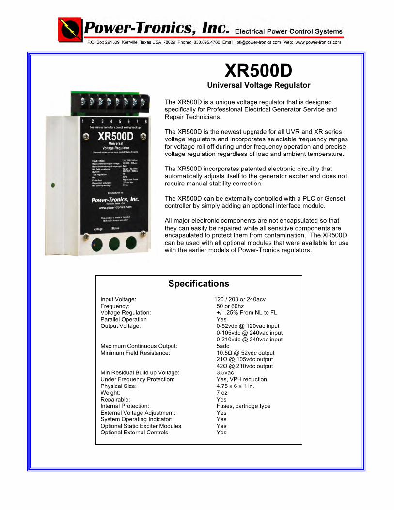
XR500D Universal Voltage Regulator
The XR500D is a unique voltage regulator that is designed specifically for Professional Electrical Generator Service and Repair Technicians. The XR500D is the newest upgrade for all UVR and XR series voltage regulators and incorporates selectable frequency ranges for voltage roll off during under frequency operation and precise voltage regulation regardless of load and ambient temperature. The XR500D incorporates patented electronic circuitry that automatically adjusts itself to the generator exciter and does not require manual stability correction. The XR500D can be externally controlled with a PLC or Genset controller by simply adding an optional interface module. All major electronic components are not encapsulated so that they can easily be repaired while all sensitive components are encapsulated to protect them from contamination. The XR500D can be used with all optional modules that were available for use with the earlier models of Power-Tronics regulators.
Specifications
Input Voltage: 120 / 208 or 240acv Frequency: 50 or 60hz Voltage Regulation: +/- .25% From NL to FL Parallel Operation Yes Output Voltage: 0-52vdc @ 120vac input 0-105vdc @ 240vac input 0-210vdc @ 240vac input Maximum Continuous Output: 5adc Minimum Field Resistance: 10.5Ω @ 52vdc output 21Ω @ 105vdc output 42Ω @ 210vdc output Min Residual Build up Voltage: 3.5vac Under Frequency Protection: Yes, VPH reduction Physical Size: 4.75 x 6 x 1 in. Weight: 7 oz Repairable: Yes Internal Protection: Fuses, cartridge type External Voltage Adjustment: Yes System Operating Indicator: Yes Optional Static Exciter Modules Yes Optional External Controls Yes
2
Caution: Read this Installation
Manual carefully.
Warning: Do not use digital equipment to read voltage, Hz, or amperage during this installation. Use only Analog sensing equipment! Failure to do so may result in damage to equipment or in personal injury! Make sure that all setup is done off line. Always wear eye protection and NEVER hold the regulator in your hand when energized. The XR500D is a Universal Voltage Regulator that can be configured several different ways to fit differing applications. Before selecting a wiring configuration for the regulator, you must know certain pieces of information about the generator and exciter to be successful in determining the correct hookup for the regulator. Show below is a guide to determine the correct connection of the regulator:
• Exciter field resistance is more than 40 ohms and exciter full load voltage is rated at 125vdc or less. (Use connection A)
• Exciter field resistance is more than 21 ohms and exciter full load voltage is
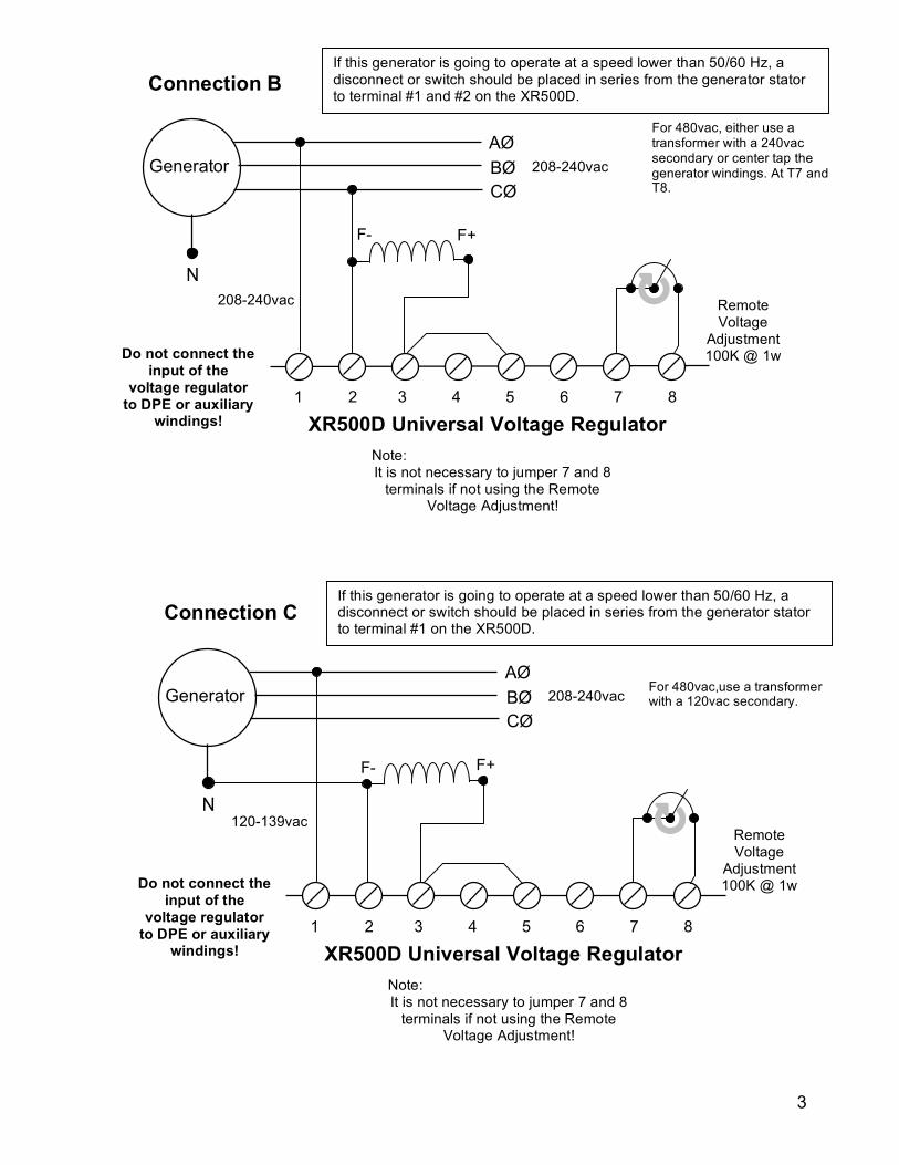
rated at 63vdc or less. (Use connection B)
• Exciter field resistance is more than 10 ohms and exciter full load voltage is rated at 32vdc or less. (Use connection C)
1 2 3 4 5 6 7 8
N
Generator AØ BØ CØ
Do not connect the input of the
voltage regulator to DPE or auxiliary
windings!
F+ F-
208-240vac
208-240vac
Connection A
XR500D Universal Voltage Regulator Note: It is not necessary to jumper 7 and 8
terminals if not using the Remote Voltage Adjustment!
Remote Voltage
Adjustment 100K @ 1w
If this generator is going to operate at a speed lower than 50/60 Hz, a disconnect or switch should be placed in series from the generator stator to terminal #1 and #2 on the XR500D.
For 480vac, either use a transformer with a 240vac secondary or center tap the generator windings. At T7 and T8.
3
1 2 3 4 5 6 7 8
N
Generator AØ BØ CØ
Do not connect the input of the
voltage regulator to DPE or auxiliary
windings!
F+ F-
208-240vac
208-240vac
Connection B
XR500D Universal Voltage Regulator Note: It is not necessary to jumper 7 and 8
terminals if not using the Remote Voltage Adjustment!
Remote Voltage
Adjustment 100K @ 1w
1 2 3 4 5 6 7 8
N
Generator AØ BØ CØ
Do not connect the input of the
voltage regulator to DPE or auxiliary
windings!
F+ F-
120-139vac
208-240vac
Connection C
XR500D Universal Voltage Regulator Note: It is not necessary to jumper 7 and 8
terminals if not using the Remote Voltage Adjustment!
Remote Voltage
Adjustment 100K @ 1w
If this generator is going to operate at a speed lower than 50/60 Hz, a disconnect or switch should be placed in series from the generator stator to terminal #1 and #2 on the XR500D.
If this generator is going to operate at a speed lower than 50/60 Hz, a disconnect or switch should be placed in series from the generator stator to terminal #1 on the XR500D.
For 480vac,use a transformer with a 120vac secondary.
For 480vac, either use a transformer with a 240vac secondary or center tap the generator windings. At T7 and T8.
4
Installation and setup 1. Install the regulator and wire up to the correct wiring diagram. 2. Turn the internal voltage control and stability control 15 or more turns counter
clockwise (left). This procedure is necessary in case the original factory settings have been altered.
3. If you are using a remote voltage adjustment, set it at 50% of adjustment. 4. Start up the prime mover and bring up to operating speed and turn on the
regulator switch. (if used) 5. Set the internal voltage adjustment to the desired voltage setting for the
generator output 6. Place the generator on line and observe the frequency and voltage.
Internal voltage
adjustment
Frequency Selection Remove jumper for 50Hz operation. This products default setting is 60Hz.
(Pull up to remove)
System
indicator light
5
Application Troubleshooting Problem: Possible Cause No Voltage 1 3 5 7 9 11 13 15 20
Pulsating Voltage 4 5 6 12 16
Flickering Voltage 4 6 7 14
High Voltage 6 7 8 9 12 13 17 18 20
Voltage Drop on Load 5 8 10 12 16
Low Voltage 5 8 12 13
Poor Voltage Regulation 2 4 10 12 13 16
No Voltage Control 13 19 20
Possible Cause: 1. Residual input voltage to the voltage regulator is below 3.5vac or fuses are open in the regulator. 2. Unbalanced generator load. 3. Open exciter field or defective generator. 4. Non linear load or defective connection in exciter field. 5. Open diode in exciter or shorted rotor in generator. 6. Loose component in voltage regulator. 7. Loose wiring connections. 8. Input voltage to regulator is too low. 9. Exciter field is grounded. 10. Non linear load or wrong selection for regulator hookup. 11. Exciter fields are reversed. 12. Wrong selection of regulator wiring configuration. 13. Defective voltage regulator. 14. SCR or Inverter drive effecting generator waveform. 15. Regulator needs external flashing circuit. 16. Isolation transformer is too small.
6
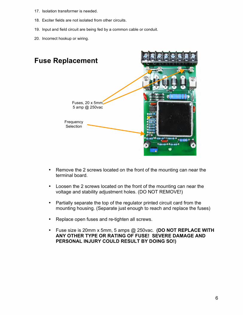
17. Isolation transformer is needed. 18. Exciter fields are not isolated from other circuits. 19. Input and field circuit are being fed by a common cable or conduit. 20. Incorrect hookup or wiring.
Fuse Replacement
• Remove the 2 screws located on the front of the mounting can near the terminal board.
• Loosen the 2 screws located on the front of the mounting can near the
voltage and stability adjustment holes. (DO NOT REMOVE!)
• Partially separate the top of the regulator printed circuit card from the mounting housing. (Separate just enough to reach and replace the fuses)
• Replace open fuses and re-tighten all screws. • Fuse size is 20mm x 5mm, 5 amps @ 250vac. (DO NOT REPLACE WITH
ANY OTHER TYPE OR RATING OF FUSE! SEVERE DAMAGE AND PERSONAL INJURY COULD RESULT BY DOING SO!)
Fuses, 20 x 5mm, 5 amp @ 250vac
Frequency Selection
7
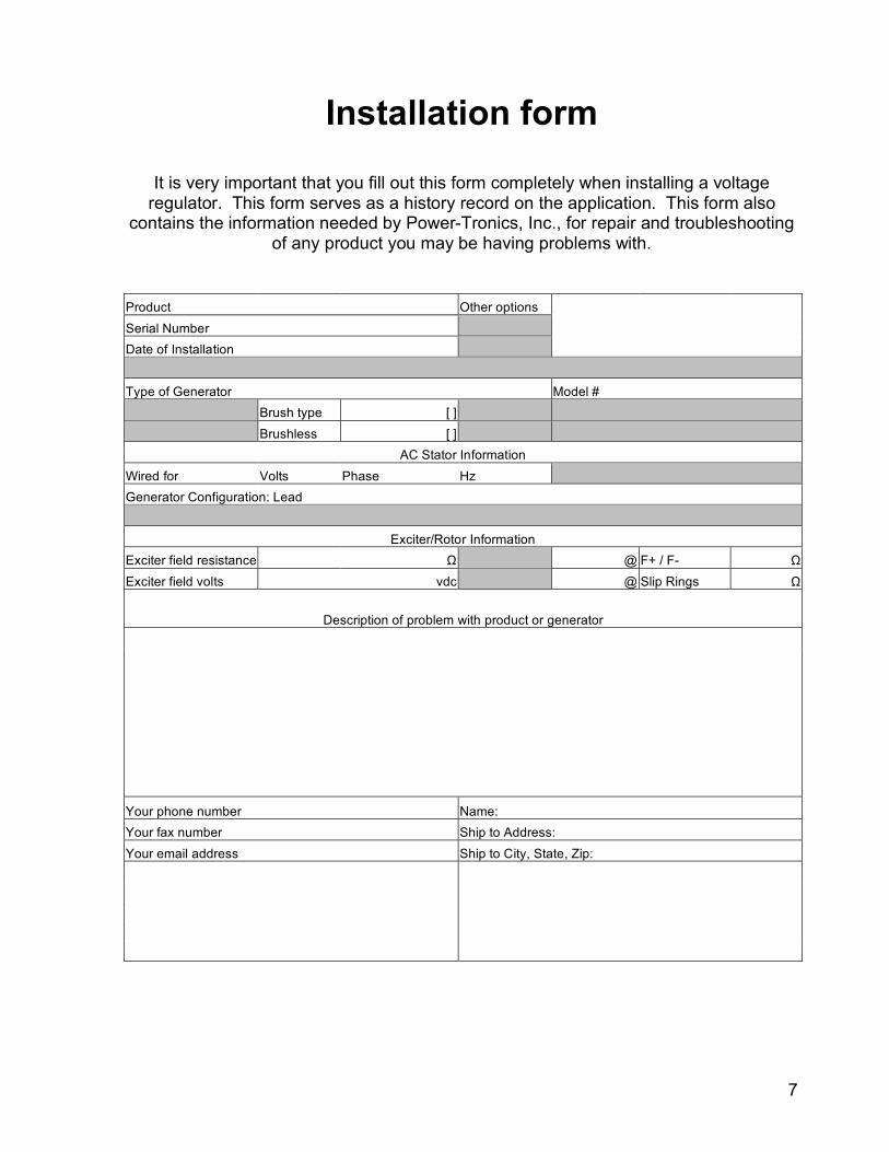
Installation form
It is very important that you fill out this form completely when installing a voltage
regulator. This form serves as a history record on the application. This form also contains the information needed by Power-Tronics, Inc., for repair and troubleshooting
of any product you may be having problems with.
Product Other options Serial Number Date of Installation
Type of Generator Model # Brush type [ ] Brushless [ ]
AC Stator Information Wired for Volts Phase Hz Generator Configuration: Lead
Exciter/Rotor Information
Exciter field resistance Ω @ F+ / F- Ω Exciter field volts vdc @ Slip Rings Ω
Description of problem with product or generator
Your phone number Name: Your fax number Ship to Address: Your email address Ship to City, State, Zip:
8
PRODUCT WARRANTY
Power-Tronics, Inc., assumes no liability for damages due to incorrect voltage or other voltage related
damages resulting from either output of the generator or input to the generator exciter system. These
problems should be protected with external devices provided by the customer such as fuses, surge
suppressors, over/under voltage and frequency controls.
Power-Tronics, Inc., warranties only parts and workmanship of this product for a period of 2 years
from the original date of purchase from Power-Tronics, Inc. Under warranty, Power-Tronics, Inc.
will replace, exchange or repair the defective product without labor or parts cost to the customer.
Remaining warranty of the original product will be transferred to the replaced or repaired product. To
obtain warranty, a copy of the original purchase receipt must be sent in with the defective product, which
clearly shows the purchase date and serial number of the defective part. A repair request form must be
sent in with the product before repairs will begin. You can obtain this form through contacting Power-
Tronics, Inc.. Send repairs to: Power-Tronics, Inc., 2802 Cobbler Ln., Kerrville Texas USA 78028.
Send in repairs only by UPS or FedEx.
Any one of the following conditions will void the warranty: Overheating of the power supply resistor on the printed circuit card.
Overheating of the SCR or freewheeling diode.
Physical damage to the printed circuit card, housing or components.
Unauthorized repair or alteration of printed circuit card.
Installation by anyone other than a qualified professional generator service technician.
Conductive or corrosive contamination of the circuit card.
Removal of our company identification from the product.
Removal of any conformal coating of the printed circuit card or components.
Overheating of foil on the printed circuit card.
Inappropriate or infeasible application
Use with any external device other than manufactured by Power-Tronics, Inc.
No other warranty is expressed or implied.
9
Bench Check Instructions 1. Wire up the regulator as shown in figure A.
2. Connect up a 120 volt 50 to 150 watt light bulb to the F+ and F- Terminals.
3. Adjust the internal voltage pot fully CCW (25 turns) or until a click is heard.
4. Input 120vac into the regulator at #1 and #2. (Fuse this input with fuses rated at 120 volts
or higher and not more than 5 amps ac)
5. Observation: The green status light should be on and the light bulb across F+ and F-
should be off. If the green status light is not on, the internal fuses are blown in the regulator
or there is internal damage to the regulator! If the green status light is not on, do not
continue this test!
6. Turn the internal voltage adjustment CW until the light bulb across F+ and F- turns fully on,
then adjust the internal voltage adjustment CCW until the light bulb is off.
7. Remove the 120vac from the regulator.
8. Connect up the regulator in configuration B and perform all of the previous steps again. In
this mode, the light bulb will only glow at half brilliance!
9. If you were able to successfully perform all of these tests, the regulator is good.
120 vac F+ F-
1 2 3 4 5 6 7 8
120 vac F+F-
1 2 3 4 5 6 7 8
Figure A
Figure B
10
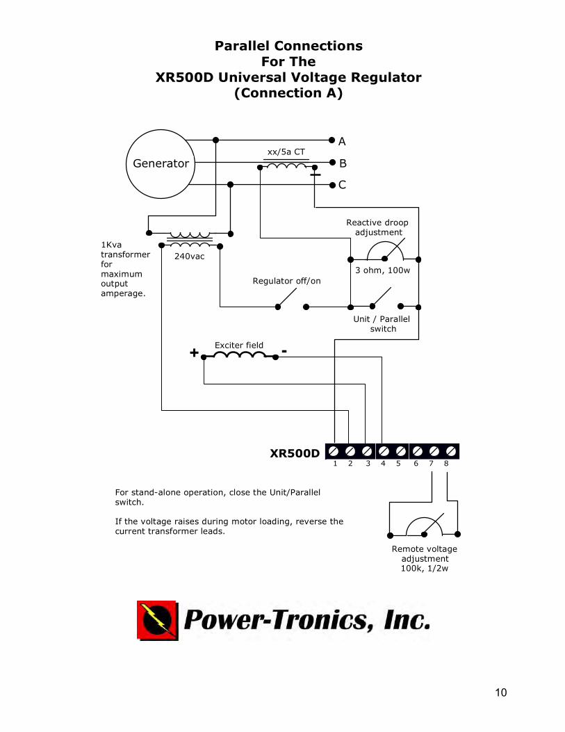
1 2 3 4 5 6 7 8
A
B
C
Generator
XR500D
3 ohm, 100w
Unit / Parallel switch
Reactive droop adjustment
Exciter field
Remote voltage adjustment 100k, 1/2w
Parallel Connections For The
XR500D Universal Voltage Regulator (Connection A)
xx/5a CT
1Kva transformer for maximum output amperage.
240vac
For stand-alone operation, close the Unit/Parallel switch.
If the voltage raises during motor loading, reverse the current transformer leads.
Regulator off/on
+ -
11
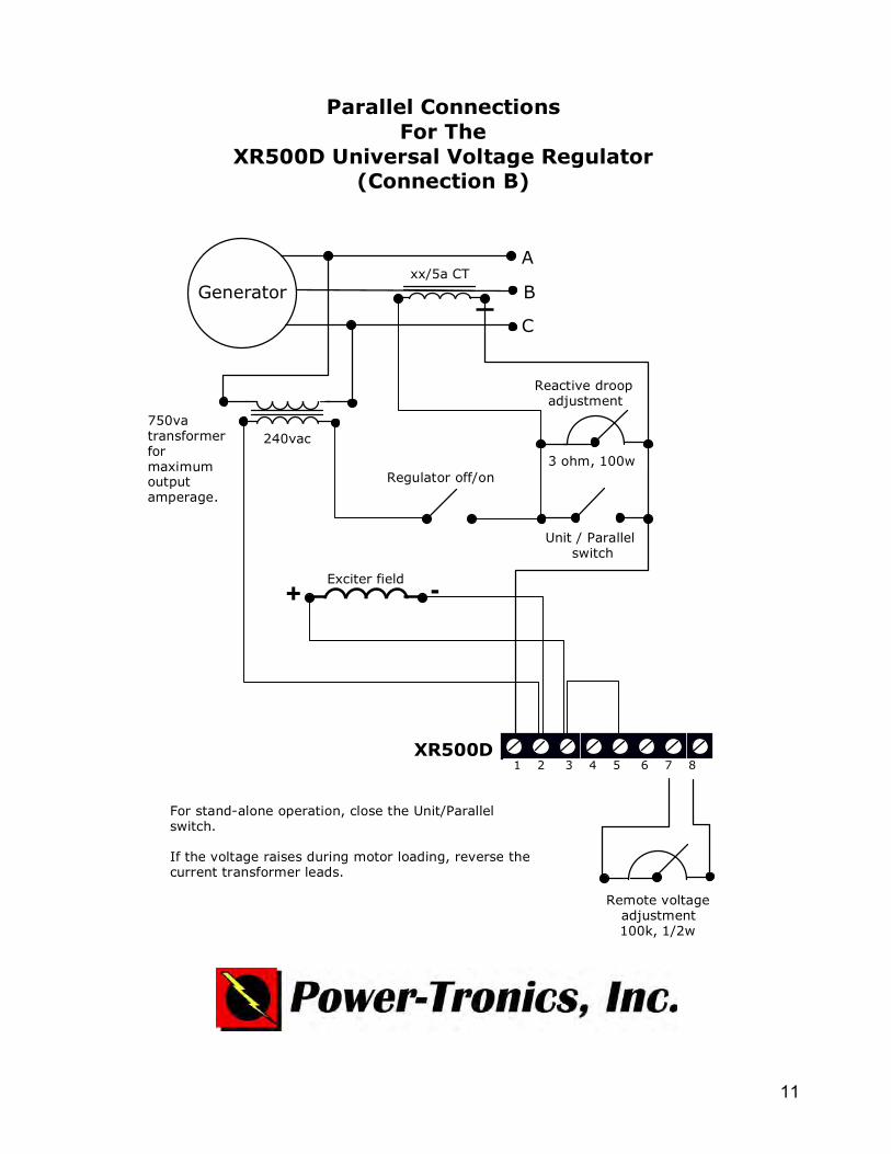
1 2 3 4 5 6 7 8
A
B
C
Generator
XR500D
3 ohm, 100w
Unit / Parallel switch
Reactive droop adjustment
Exciter field
Remote voltage adjustment 100k, 1/2w
Parallel Connections For The
XR500D Universal Voltage Regulator (Connection B)
xx/5a CT
750va transformer for maximum output amperage.
240vac
For stand-alone operation, close the Unit/Parallel switch.
If the voltage raises during motor loading, reverse the current transformer leads.
Regulator off/on
+ -
12
1 2 3 4 5 6 7 8
A
B
C
Generator
AC1 AC2 F+ F-
SE350 White Red Gray
XR500D
3 ohm, 100w
Unit / Parallel switch
Regulator off/on
Reactive droop adjustment
Exciter field
Remote voltage adjustment 100k, 1/2w
Parallel Connections for the XR500D Universal Voltage Regulator when used with the SE350 Static
Exciter Module.
xx/5 CT
5kva transformer for maximum output amperage.
240vac
For stand-alone operation, close the Unit/Parallel switch.
If the voltage raises during motor loading, reverse the current transformer leads.
13
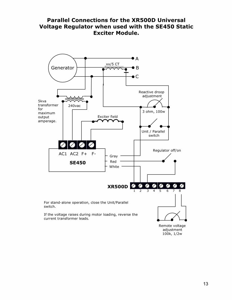
1 2 3 4 5 6 7 8
A
B
C
Generator
AC1 AC2 F+ F-
SE450 White Red Gray
XR500D
3 ohm, 100w
Unit / Parallel switch
Regulator off/on
Reactive droop adjustment
Exciter field
Remote voltage adjustment 100k, 1/2w
Parallel Connections for the XR500D Universal Voltage Regulator when used with the SE450 Static
Exciter Module.
xx/5 CT
5kva transformer for maximum output amperage.
240vac
For stand-alone operation, close the Unit/Parallel switch.
If the voltage raises during motor loading, reverse the current transformer leads.
14
ARM
Main Rotor
Shunt Field
Interpole
A1 A2
F1 F2
C2 C1
Rheostat Or
Voltage Regulator
ARM
Main Rotor
Shunt Field
Interpole
A1 A2
F1 F2
C2 C1
Voltage Regulator F+ and F-
Switch polarity if buildup does not
occur
Original Wiring
Converted Wiring
Conversion Diagram To Change From Older Shunt Wound Voltage Regulation To Newer Solid State Voltage VR, UVR And XR Universal Voltage Regulators.
15
XR500C XR500D XR500C-400 UVR501
UVR501-400 UVR500
AFM500X shown connected to an XR or UVR series Power-Tronics voltage regulator in the AUTO FLASH configuration.
AFM500X shown connected to an XR or UVR series Power-Tronics voltage regulator in the BATTERY FLASH configuration.
B+ 12/24vdc
6
2
5
1
4 3
XR500C
XR500D XR500C-400 UVR501 UVR501-400
UVR500
6
2
5
1
10Ω, 100w resistor
PB switch, fuel or oil pressure, speed switch or relay contact.
Note: Battery negative must be connected to the generator neutral and not to the F- of the exciter!