20
OPERATOR MANUAL ISSUE 1 XTM182i

OperatOr Manual ISSue 1
XTM182i

WelcomeThank you and congratulations on choosing Parweld. This Owner’s Manual is designed to help you get
the most out of your Parweld products. Please take time to read the Safety precautions. They will
help you protect yourself against potential hazards in the workplace. With proper maintenance this
equipment should provide years of reliable service. All our systems conform to ISO9001: 2000 and
are independently audited by NQA.
The entire product range carries the CE mark, and is constructed in accordance with European
directives and the product specific standards where they apply.
Further InformationParweld is the UK’s leading supplier of MIG, TIG and Plasma torches and consumables.
For more information about Parweld’s complete range visit: www.parweld.com

CO
nten
tS
Contents Page1.0 Safety precautions 4
2.0 product description 5
3.0 Technical Specifications 6
4.0 Description of controls 6
5.0 Installation 7
5.1 Unpacking the Machine 7
5.2 Location 7
5.3 Input and grounding connection 7
5.4 Output Polarity Connections 7
5.5 Changing drive roll sets 7
5.6 Welding wire installation 7
5.7 torch installation 8
5.8 Work return lead connection 9
5.9 Shielding gas connection 9
6.0 Operation 9
6.1 Feeding wire electrode 9
6.2 Spot Weld Mode 9
6.3 Optimising weld parameters 9
7.0 Fault finding 10 8.0 accessories 11
8.1 Drive rolls 11
8.2 Torch spares 12
8.3 Gas equipment 13
9.0 EC declaration of conformity 14
9.1 RoHS Compliance Declaration 14
9.2 WEEE Statement 15
9.3 Statement of warranty 15

www.parweld.com
4
1.0 Safety precautionseleCtrIC SHOCK can kill.
Touching live electrical parts can cause fatal shocks or severe burns. The electrode and work circuit is electrically live whenever the output is on. The input power circuit and machine internal circuits are also live when power is on. In semiautomatic or automatic wire welding, the wire, wire reel, drive roll housing, and all metal parts touching the welding wire are electrically live. Incorrectly installed or improperly grounded equipment is a hazard.
Do not touch live electrical parts.
Wear dry, sound insulating gloves and body protection.
Insulate yourself from work and ground using dry insulating mats or covers big enough to prevent any physical contact with the work ground.
Additional safety precautions are required when any of the following electrically hazardous conditions are present: in damp locations or while wearing wet clothing; on metal structures such as floors, gratings, or scaffolds; when in cramped positions such as sitting, kneeling, or lying; or when there is a high risk of unavoidable or accidental contact with the work piece or ground. For these conditions, use the following equipment in order presented: 1) a semiautomatic DC constant voltage (wire) welder, 2) a DC manual (stick) welder, And, do not work alone!
Disconnect input power before installing or servicing this equipment. Lockout/tagout input power according to Safety Standards.
Properly install and ground this equipment according to national and local standards.
Always verify the supply ground - check and ensure that input power cable ground wire is properly connected to ground terminal in the receptacle outlet.
When making input connections, attach proper grounding conductor first - double-check connections.
Frequently inspect input power cable for damage or bare wiring - replace cable immediately if damaged - bare wiring can kill.
Turn off all equipment when not in use.
Do not use worn, damaged, under sized, or poorly spliced cables.
Do not drape cables over your body.
If earth grounding of the work piece is required, ground it directly with a separate cable.
Do not touch electrode if you are in contact with the work, ground, or another electrode from a different machine.
Use only well-maintained equipment. Repair or replace damaged parts at once. Maintain unit according to manual.
Wear a safety harness if working above floor level.
Keep all panels and covers securely in place.
Clamp work cable with good metal-to-metal contact to work piece or worktable as near the weld as practical.
Insulate work clamp when not connected to work piece to prevent contact with any metal object.
Welding produces fumes and gases. Breathing these fumes and gases can be hazardous to your health.
FuMeS anD GaSeS can be hazardous.Keep your head out of the fumes. Do not breathe the fumes.If inside, ventilate the area and/or use local forced ventilation at the arc to remove welding fumes and gases.
If ventilation is poor, wear an approved respirator.
Read and understand the Material Safety Data Sheets (MSDS’s) and the manufacturer’s instructions for metals, consumable, coatings, cleaners, and de-greasers.
Work in a confined space only if it is well ventilated, or while wearing an air-supplied respirator. Always have a trained watch person nearby. Welding fumes and gases can displace air and lower the oxygen level causing injury or death. Be sure the breathing air is safe.
Do not weld in locations near de-greasing, cleaning, or spraying operations. The heat and rays of the arc can react with vapours to form highly toxic and irritating gases.
Do not weld on coated metals, such as galvanized, lead, or cadmium plated steel, unless the coating is removed from the weld area, the area is well ventilated, and while wearing an air-supplied respirator. The coatings and any metals containing these elements can give off toxic fumes if welded.
arC raYS can burn eyes and skin.Arc rays from the welding process produce intense, visible and invisible (ultraviolet and infrared) rays that can burn eyes and skin. Sparks fly off from the weld.
Wear an approved welding helmet fitted with a proper shade of filter lenses to protect your face and eyes when welding or watching
Wear approved safety glasses with side shields under your helmet.
Use protective screens or barriers to protect others from flash, glare and sparks; warn others not to watch the arc.
Wear protective clothing made from durable, flame resistant material (leather, heavy cotton, or wool) and foot protection. Welding on closed containers, such as tanks, drums, or pipes, can cause them to blow up. Sparks can fly off from the welding arc. The flying sparks, hot work piece, and hot equipment can cause fires and burns. Accidental contact of electrode to metal objects can cause sparks, explosion, overheating, or fire. Check and be sure the area is safe before doing any welding.

www.parweld.com www.parweld.com
5
WELDING can cause fire or explosion.Remove all flammables within 10m of the welding arc. If this is not possible, tightly cover them with approved covers.
Do not weld where flying sparks can strike flammable material.
Protect yourself and others from flying sparks and hot metal.
Be alert that welding sparks and hot materials from welding can easily go through small cracks and openings to adjacent areas.
Watch for fire, and keep a fire extinguisher nearby. Be aware that welding on a ceiling, floor, bulkhead, or partition can cause fire on the hidden side.
Do not weld on closed containers such as tanks, drums, or pipes, unless they are properly prepared according to local regulations
Connect work cable to the work as close to the welding area as practical to prevent welding current from travelling along, possibly unknown paths and causing electric shock, sparks, and fire hazards.
Cut off welding wire at contact tip when not in use.
Wear oil-free protective garments such as leather gloves, heavy shirt, cuffless trousers, high shoes, and a cap. Remove any combustibles, such as a butane lighter or matches, from your person before doing any welding.
FlYInG Metal can injure eyes.Welding, chipping, wire brushing, and grinding cause sparks and flying metal. As welds cool they can throw off slag. Wear approved safety glasses with side shields even under your welding helmet.
BuIlDup OF GaS can injure or kill.Shut off shielding gas supply when not in use. Always ventilate confined spaces or use approved air-supplied respirator.
HOt partS can cause severe burns.Do not touch hot parts with bare handed.
Allow cooling period before working on gun or torch.
To handle hot parts, use proper tools and/or wear heavy, insulated welding gloves and clothing to prevent burns.
MaGnetIC FIelDS can affect pacemakers.Pacemaker wearers keep away.
Wearers should consult their doctor before going near arc welding, gouging, or spot welding operations.
NOISE can damage hearing.Noise from some processes or equipment can damage hearing.
Wear approved ear protection if noise level is high.
Shielding gas cylinders contain gas under high pressure.
CYLINDERS can explode if damaged.Protect compressed gas cylinders from excessive heat, mechanical shocks, physical damage, slag, open flames, sparks, and arcs. Install cylinders in an upright position by securing to a stationary support or cylinder rack to prevent falling or tipping. Keep cylinders away from any welding or other electrical circuits. Never drape a welding torch over a gas cylinder. Never allow a welding electrode to touch any cylinder. Never weld on a pressurized cylinder - explosion will result. Use only correct shielding gas cylinders, regulators, hoses, and fittings designed for the specific application; maintain them and associated parts in good condition.
Turn face away from valve outlet when opening cylinder valve.
Use the right equipment, correct procedures, and sufficient number of persons to lift and move cylinders.
Read and follow instructions on compressed gas cylinders, associated equipment, and Compressed Gas Association (CGA)
2.0 product Description The XTM 182i is a complete semiautomatic constant voltage DC arc welding machine built to meet CE specifications. It combines a constant voltage power source and a constant speed wire feeder with a microcomputer-based controller to form a reliable high-performance welding system. A simple control scheme, consisting of range voltage and wire feed speed controls, provides versatility with ease of use and accuracy. Other features include wire reel spindle with adjustable brake for 15kg wire spools (300mm), an integral gas cylinder mounting undercarriage, an adjustable Argon flow regulator with cylinder pressure gauge and inlet hose, a Parweld MIG torch, and a 3.0m work cable with clamp.

www.parweld.com
6
3.0 technical Specifications
The XTM 182i, Is a compact type machines with integrated wire feed units for use with single phase 230V supply. The machine uses inverter technology to allow MIG , TIG and MMA welding to be performed.
Feature XtM182i
Input voltage 230V +/-10%
Hz 50/60phases 1
Wire drive 4 roll
Current Draw (a) 26
rated input capacitance KVa
7.4
No-load voltage V
69V
Rated working voltage V
23
LIFT Arc welding current a
15-180
MMA welding current 20-160
MIG welding current a
30-180
Fuse Rating(a)
32
Output current (a) 35-185
4.0 Description of Controls1. POWER INDICATOR: When the machine is turned on, the
power indicator will be on.2. ALARM INDICATOR: When the thermal indicator is on, it shows
the machine is overloaded and the internal temperature is too high. Weld output will turn off automatically but the fan will still be working. When the internal temperature is decreased, the overload light will turn off and the machine will be ready to weld
3. VRD INDICATOR: When the VRD indicator is on, it means the welder’s output voltage is safe ≤13V, it will be off when the welder is working..
4. CURRENT DISPLAY INDICATOR: It will be display current preset, and display real-current when the welder is working.
5. LEFT ADJUST KNOB: Its main function is adjusting welding current; Users can press down the knob in MIG/MAG then wire inching function will be activated.
6. VOLTAGE DISPLAY INDICATOR: It will be display Arc-Force preset in MMA, and display voltage preset in MIG/MAG, and display real-voltage when the welder is working.
7. MIDDLE ADJUST KNOB: Its main function is adjusting Arc-Force in MMA, and adjusting welding voltage in MIG/MAG. Press down the knob in MIG/MAG, and the gas-check function will be active.
8. VOLTAGE AND ARC LENGTH INDICATOR: 9. MMA ARCFORCE PRE-SET INDICATOR: 10. MIG/MAG ELECTRICAL INDUCTOR ADJUST KNOB: Its main
function is adjusting arc’s dynamic in MIG/MAG.11. CURRENT INDICATOR: When the indicator is on, it means the
current is displayed.12. WFS INDICATOR: When the indicator is on ,it means the wire
speed is display(m/min).13. WELD FUNTION SELECTION BUTTON: Users can select
MMA LIFT Arc or MIG/MAG function by this button, and the indicators at the left part of button will indicate the selection weld function.
14. MIG/MAG TRIGGER MODE BUTTON: Users can select gun trigger mode in MIG/MAG by this button, and the indicators at the left part of button will indicate the selection mode.
15. MIG/MAG GAS SELECTION BUTTON: Users can select protect gas by this button, and the indicators at the left part of button will indicate the selection gas.
16. MIG/MIG WIRE DIAMETER SELECTION BUTTON: Users can select wire diameter by this button, and the indicators at the left part of button will indicate the selection wire.
17. Torch connector The Euro connector provided the external connection for the welding torch.
18. Work return lead connection. This socket allows connection of the work return lead to the front of the machine.
19. Gas cylinder restraint chain Use to secure the gas cylinder when mounted on the rear of the machine
20. Shielding gas input connection 3/8 BSP male connection for the shielding gas input.
21. Mains input connection Input connection for the pre installed mains cable.
22. Cylinder stand Rear stand for the gas cylinder23. Wire spool holder24. Pressure adjuster Used to adjust the pressure allied by the feed
rollers on the welding wire.
3
6
9
10
7
16
2
1
11
12
4
5
13
14
15
www.parweld.com www.parweld.com
7
25. Pressure roller Plain roller used to apply pressure on the welding wire
26. Feed Roller Grooved roller used to drive the welding wire up the torch the size of the roller should match the size of the wire in use.
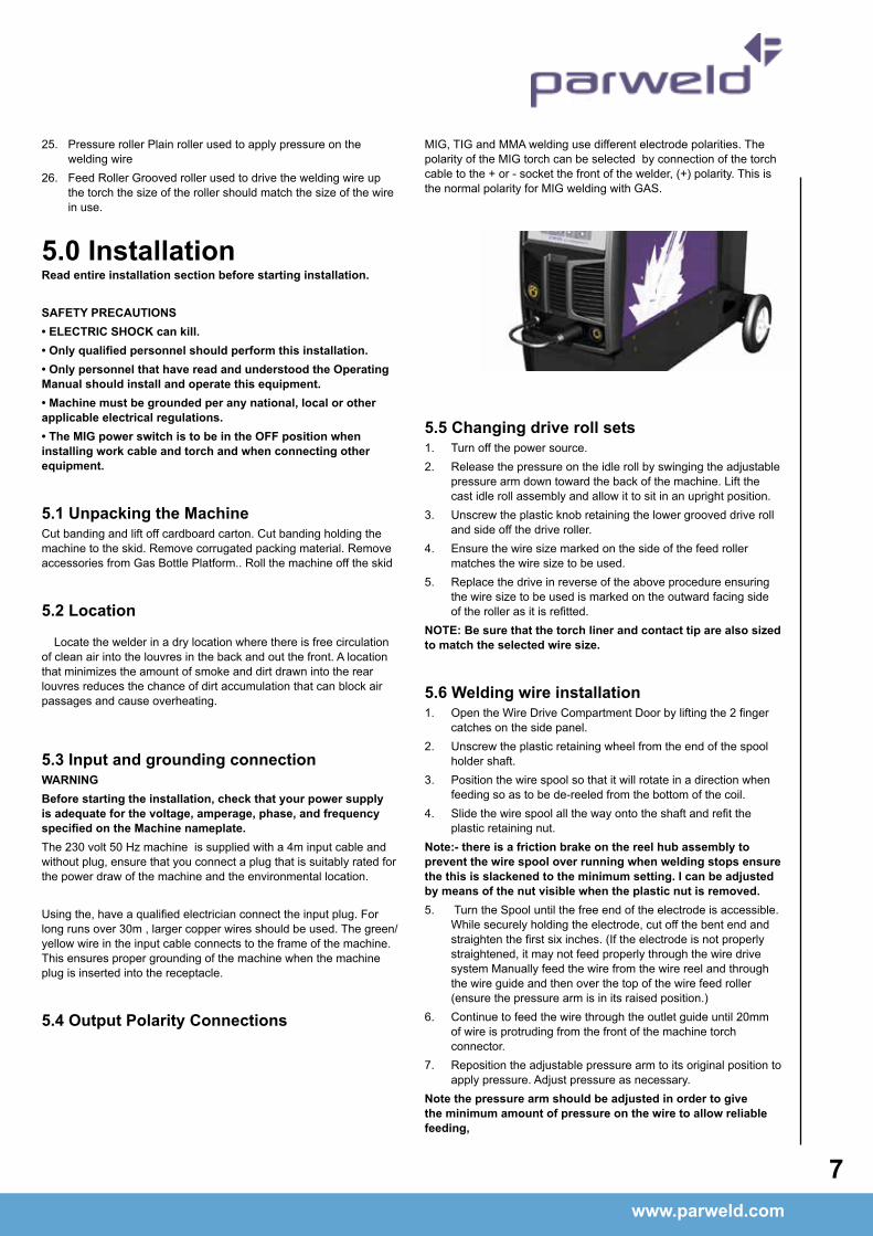
5.0 InstallationRead entire installation section before starting installation.
SaFetY preCautIOnS• ELECTRIC SHOCK can kill.• Only qualified personnel should perform this installation.• Only personnel that have read and understood the Operating Manual should install and operate this equipment.• Machine must be grounded per any national, local or other applicable electrical regulations.• The MIG power switch is to be in the OFF position when installing work cable and torch and when connecting other equipment.
5.1 Unpacking the MachineCut banding and lift off cardboard carton. Cut banding holding the machine to the skid. Remove corrugated packing material. Remove accessories from Gas Bottle Platform.. Roll the machine off the skid
5.2 location
Locate the welder in a dry location where there is free circulation of clean air into the louvres in the back and out the front. A location that minimizes the amount of smoke and dirt drawn into the rear louvres reduces the chance of dirt accumulation that can block air passages and cause overheating.
5.3 Input and grounding connection WarnInGBefore starting the installation, check that your power supply is adequate for the voltage, amperage, phase, and frequency specified on the Machine nameplate.The 230 volt 50 Hz machine is supplied with a 4m input cable and without plug, ensure that you connect a plug that is suitably rated for the power draw of the machine and the environmental location.
Using the, have a qualified electrician connect the input plug. For long runs over 30m , larger copper wires should be used. The green/yellow wire in the input cable connects to the frame of the machine. This ensures proper grounding of the machine when the machine plug is inserted into the receptacle.
5.4 Output polarity Connections
MIG, TIG and MMA welding use different electrode polarities. The polarity of the MIG torch can be selected by connection of the torch cable to the + or - socket the front of the welder, (+) polarity. This is the normal polarity for MIG welding with GAS.
5.5 Changing drive roll sets1. Turn off the power source.2. Release the pressure on the idle roll by swinging the adjustable
pressure arm down toward the back of the machine. Lift the cast idle roll assembly and allow it to sit in an upright position.
3. Unscrew the plastic knob retaining the lower grooved drive roll and side off the drive roller.
4. Ensure the wire size marked on the side of the feed roller matches the wire size to be used.
5. Replace the drive in reverse of the above procedure ensuring the wire size to be used is marked on the outward facing side of the roller as it is refitted.
nOte: Be sure that the torch liner and contact tip are also sized to match the selected wire size.
5.6 Welding wire installation1. Open the Wire Drive Compartment Door by lifting the 2 finger
catches on the side panel.2. Unscrew the plastic retaining wheel from the end of the spool
holder shaft.3. Position the wire spool so that it will rotate in a direction when
feeding so as to be de-reeled from the bottom of the coil.4. Slide the wire spool all the way onto the shaft and refit the
plastic retaining nut.note:- there is a friction brake on the reel hub assembly to prevent the wire spool over running when welding stops ensure the this is slackened to the minimum setting. I can be adjusted by means of the nut visible when the plastic nut is removed.5. Turn the Spool until the free end of the electrode is accessible.
While securely holding the electrode, cut off the bent end and straighten the first six inches. (If the electrode is not properly straightened, it may not feed properly through the wire drive system Manually feed the wire from the wire reel and through the wire guide and then over the top of the wire feed roller (ensure the pressure arm is in its raised position.)
6. Continue to feed the wire through the outlet guide until 20mm of wire is protruding from the front of the machine torch connector.
7. Reposition the adjustable pressure arm to its original position to apply pressure. Adjust pressure as necessary.
Note the pressure arm should be adjusted in order to give the minimum amount of pressure on the wire to allow reliable feeding,

www.parweld.com
8
5.7 torch installation
Your Parweld MIG/MAG Welding Torch has been supplied ready to weld. It has been supplied with the standard consumables denoted in the product brochure.
To connect the torch to the power source:-
1. Remove the tip adaptor and contact tip2. Inch the wire from the exit of the wire guide on the feed unit
as Figure 1. Ensure that it does not short out on any machine panels.
3. Carefully slide the electrode wire into the torch liner and slowly locate the torch gun plug body into the feed unit central connector and tighten the gun plug nut as Figure 2
Note; To aid the initial location of a new torch and to prevent damage to the gas nipple O-ring a very light application of
Fig 1 Fig 2
x
4. Keeping the torch as straight as possible, use the power source inch facility or torch trigger to feed the electrode wire 50mm from the end of the liner conduit.
5.diffuser, contact tip and gas nozzle.
6. Trim the electrode wire to within 5mm of the face of the nozzle, this will facilitate jolt free arc initiation.
7.for your application.
8.806001.
9. If you are setting a water-cooled torch ensure you have the
water to prevent irreparable torch failure, a minimum of 1.2 l/min is recommended.
Parweld recommend the use of its XTS water recirculation system
Plasma welding torches.
hose delivers cold water directly to the prime source of heat, the swan neck and consumable. The re circulated water is then passed through the torch power cable to cool the power cable as it is returned to the cooler through the red water return lead.
Ensure all air is removed from the water cooling circuit before welding.
5.8 Work return lead connectionInsert the work return lead connector into the receptacle on the front panel of the machine and twist it clockwise until tightly secured. Connect the earth clamp to the work piece as close as possible to the point to be welded and ensure that a good electrical connection is created to bare metal.
5.9 Shielding gas connection
1. Using the gas hose supplied connect the hose to the gas inlet connection on the rear of the machine and tighten it with a spanner.
2. Connect the opposite end of the gas hose to the output connection of a gas regulator capable of supplying the correct
Note if the gas cylinder is to be stored on the back of the machine ensure it is secured using the retention chain provided
6.0 Operation1. Switch on the machine using the mains on/off switch, This lights
the Green LED above the voltage selector switch.2. Select the welding mode using push button (13) and switching
option with Button (14)
6.1 MIG welding Feeding wire electrodeYou can MIG weld in 2 modes Manual and Synergic the manual
mode takes more skill to setup.
Synergic MIG,
Select the Synergic MIG mode using button (13)
Select the wire type using button (15)
Select the wire diameter using button (16)
Rotating the amperage button (5) select the desired welding amperage. you can refer to the table at the rear of the instruction book for recommended welding amperages. The machine will adjust the welding voltage automatically but you may trim it and the inductance to your personal preference by adjustment of the Voltage knob (7) and inductance (10) The voltage will increase or decrease penetration and the inductance affects the arc stability and droplet transfer.
Manual MIG
Select the Manual MIG mode using button (13)
Select the desired welding voltage using the knob (7)
Select the desired welding amperage (wire speed) using the knob (5)

www.parweld.com www.parweld.com
9
Note: Check that drive rolls, and torch parts are correct for the wire size and type being used.
3. The optimum idle roll pressure varies with type of wire, wire diameter, surface conditions, lubrication, and hardness. As a general rule, hard wires may require greater pressure, and soft, or aluminium wire, may require less pressure than the factory setting. The optimum idle roll setting can be determined as follows:
4. Press end of gun against a solid object that is electrically isolated from the welder output and press the gun trigger for several seconds.
5. If the wire “bird nests”, jams or breaks at the drive roll, the idle roll pressure is too great. Back the adjustment knob out 1/2 turn, run new wire. If the only result was drive roll slippage, loosen the Hand nut on the central connector and pull the gun forward about 6” (15cm) away from the power source. There should be a slight waviness in the exposed wire. If there is not waviness, the pressure is too low. Tighten the adjustment knob 1/4 turn, reinstall the gun cable and repeat the above steps.
1. When triggering, the electrode and drive mechanism are electrically “LIVE” relative to work and ground and remain “LIVE” several seconds after the gun trigger is released.
WarnInGWhen using an open arc process, it is necessary to use correct eye, head, and body protection.
2. Position wire over joint. The end of the wire may be lightly touching the work.
3. Lower welding helmet, operate gun trigger, and begin welding. Hold the gun so the contact tip to work distance is about 3/8” (10 mm).
4. To stop welding, release the gun trigger and then pull the gun away from the work after the arc goes out.
5. When no more welding is to be done, close valve on gas cylinder (if used), momentarily operate gun trigger to release gas pressure and turn off the machine.
NOTE These settings are guidelines only. Material and wire type, joint design, fit up, position, shielding gas, etc. affect settings. Produce test welds to be sure they comply to specifications.
Material thickness determines weld parameters.1. Convert Material Thickness to Amperage (A) (0.25mm= 1 Amp)
3.2mm = 125 A2. Select Wire SizeAmperage Range Wire Size40 - 145 A 0.8 mm50 - 180 A 1.0 mm75 - 250 A 1.2 mm
3. Select Wire Speed (Amperage)
Wire Size Feed speed0.8 mm 0.05m/min per Amp1.0 mm 0.04m/min per Amp1.2 mm 0.025m/min per AmpSo based on 3.2 mm material thickness amperage should be 125A if using 1.0mm wire then the wire feed speed should be 0.04 X 125= 5m/minWire speed (amperage) controls weld penetration4. Select Voltage. Voltage controls height and width of weld bead.Low Voltage: wire stubs into workHigh Voltage: arc is unstable (spatter)
Set voltage midway between high/low voltages.And then fine tune accordingly
6.2 MMA/TIG welding
Output polarity ConnectionsElectrode polarityMMA electrodes are generally connected to the ‘+’ terminal and the work lead to the ‘-‘terminalBut if in doubt consult the electrode manufacturer’s literature.IF TIG welding the torch should always be connected to the ‘-’ terminal.
torch installationMMA cable connectionsConnect electrode lead to positive terminal on the front panel
TIG welding cable connectionConnect the TIG torch to the - terminal
Work return lead connectionMMA cable connectionsConnect work lead to negative terminal
TIG weldingConnect the work return lead to the + terminal
MMA/TIG welding Operation
WarnInGWhen using an open arc process, it is necessary to use correct
eye, head, and body protection.
MMA Welding Guide

www.parweld.com
10
Using the selector button 13 toggle through the functions until the MMA light is illuminated
You can adjust he welding amperage using the knob (5) and the arc force using the knob (7)Effects of MMA welding various materials
High tensile and alloy steelsThe two most prominent effects of welding these steels are the formation of a hardened zone in the weld area, and, if suitable precautions are not taken, the occurrence in this zone of under-bead cracks. Hardened zone and under-bead cracks in the weld area may be reduced by using the correct electrodes, preheating, using higher current settings, using larger electrodes sizes, short runs for larger electrode deposits or tempering in a furnace.
Manganese steelsThe effect on manganese steel of slow cooling from high temperatures is enbrittlement. For this reason it is absolutely essential to keep manganese steel cool during welding by quenching after each weld or skip welding to distribute the heat.
Cast ironMost types of cast iron, except white iron, are weldable. White iron, because of its extreme brittleness, generally cracks when attempts are made to weld it. Trouble may also be experienced when welding white-heart malleable, due to the porosity caused by gas held in this type of iron.
Copper and alloysThe most important factor is the high rate of heat conductivity of copper, making preheating of heavy sections necessary to give proper fusion of weld and base metal.
Types of electrodesArc welding electrodes are classified into a number of groups depending on their applications. There are a great number of electrodes used for specialized industrial purposes which are not of particular interest for everyday general work. These include some low hydrogen types for high tensile steel, cellulose types for welding large diameter pipes, etc. The range of electrodes dealt with in this publication will cover the vast majority of applications likely to be encountered; are all easy to use and all will work on even the most basic of welding machines.
Metals being joined & electrode commentsMild steel 6013 ideal electrodes for all general purpose work. Features include outstanding operator appeal, easy arc starting and low spatter.
Mild steel 7014 all positional electrode for use on mild and galvanized steel furniture, plates, fences, gates, pipes and tanks etc. Especially suitable for vertical down welding.
Cast iron 99% nickel suitable for joining all cast irons except white cast iron
CO
ntr
OlS
Stainless steel 318l-16 high corrosion resistance. Ideal for dairy work, etc. On stainless steels.
TIG Welding guide
Using the selector button 13 toggle through the functions until the DC TIG light is illuminatedYou can adjust he welding amperage using the knob (5) and the arc force using the knob (7)
Tig welding cable connectionConnect the TIG torch to the - terminal and the work lead to the + terminal for direct current straight polarity. Direct current straight polarity is the most widely used polarity for DC TIG welding. It allows limited wear of the electrode since 70% of the heat is concentrated at the work piece. Connect the gas hose on the TIG torch to the gas outlet on the gas regulator. Move the selector switch on the front panel of the machine to the LIFT-TIG position.
Torch starting in LIFT-TIG modeEnsure the gas supply is switched on and gas is flowing from the front of the torch nozzle. Briefly contact the tip of the tungsten electrode down onto the work piece with the torch at around 700 from vertical, lift the torch up from the work piece to draw out an arc. To prevent melting of the end of the tungsten so this in a smoth rapid movementTIG welding guide ranges
7.0 Fault Finding
www.parweld.com www.parweld.com
11
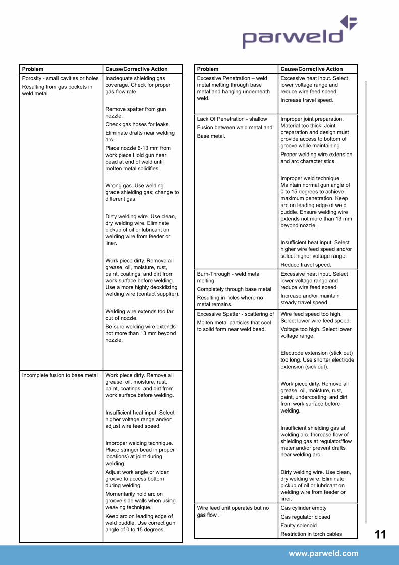
problem Cause/Corrective actionExcessive Penetration – weld metal melting through base metal and hanging underneath weld.
Excessive heat input. Select lower voltage range and reduce wire feed speed.Increase travel speed.
Lack Of Penetration - shallowFusion between weld metal andBase metal.
Improper joint preparation. Material too thick. Joint preparation and design must provide access to bottom of groove while maintainingProper welding wire extension and arc characteristics.
Improper weld technique. Maintain normal gun angle of 0 to 15 degrees to achieve maximum penetration. Keep arc on leading edge of weld puddle. Ensure welding wire extends not more than 13 mm beyond nozzle.
Insufficient heat input. Select higher wire feed speed and/or select higher voltage range.Reduce travel speed.
Burn-Through - weld metal meltingCompletely through base metalResulting in holes where no metal remains.
Excessive heat input. Select lower voltage range and reduce wire feed speed.Increase and/or maintain steady travel speed.
Excessive Spatter - scattering ofMolten metal particles that cool to solid form near weld bead.
Wire feed speed too high. Select lower wire feed speed.Voltage too high. Select lower voltage range.
Electrode extension (stick out) too long. Use shorter electrode extension (sick out).
Work piece dirty. Remove all grease, oil, moisture, rust, paint, undercoating, and dirt from work surface before welding.
Insufficient shielding gas at welding arc. Increase flow of shielding gas at regulator/flow meter and/or prevent drafts near welding arc.
Dirty welding wire. Use clean, dry welding wire. Eliminate pickup of oil or lubricant on welding wire from feeder or liner.
Wire feed unit operates but no gas flow .
Gas cylinder emptyGas regulator closedFaulty solenoidRestriction in torch cables
problem Cause/Corrective actionPorosity - small cavities or holesResulting from gas pockets in weld metal.
Inadequate shielding gas coverage. Check for proper gas flow rate.
Remove spatter from gun nozzle.Check gas hoses for leaks. Eliminate drafts near welding arc.Place nozzle 6-13 mm from work piece Hold gun near bead at end of weld until molten metal solidifies.
Wrong gas. Use welding grade shielding gas; change to different gas.
Dirty welding wire. Use clean, dry welding wire. Eliminate pickup of oil or lubricant on welding wire from feeder or liner.
Work piece dirty. Remove all grease, oil, moisture, rust, paint, coatings, and dirt from work surface before welding. Use a more highly deoxidizing welding wire (contact supplier).
Welding wire extends too far out of nozzle.Be sure welding wire extends not more than 13 mm beyond nozzle.
Incomplete fusion to base metal Work piece dirty. Remove all grease, oil, moisture, rust, paint, coatings, and dirt from work surface before welding.
Insufficient heat input. Select higher voltage range and/or adjust wire feed speed.
Improper welding technique. Place stringer bead in proper locations) at joint during welding.Adjust work angle or widen groove to access bottom during welding.Momentarily hold arc on groove side walls when using weaving technique.Keep arc on leading edge of weld puddle. Use correct gun angle of 0 to 15 degrees.

www.parweld.com
12
problem Cause/Corrective actionWire feed unit operates, but does not feed
Insufficient drive roll pressureIncorrect drive rollsExcessive wire spool brake tensionIncorrect linerBlocked linerBird nestingBurn back
Bird nesting Excessive feed roll pressureIncorrect or blocked linerIncorrect contact tip sizeContact tip overheatingRestriction in torch cableMisaligned drive rolls or wire guidesExcessive cable kinkage
Burn back Improper voltage settingImproper stick outErratic wire feedIncorrect or blocked linerContact tip overheatingExcessive cable kinking
Erratic Wire Feeding or Arc Improper drive roll tensionImproper drive roll sizeWorn drive rollsIncorrect or blocked linerIncorrect wire guide sizeMisaligned drive rolls or wire guideGaps at liner or wire guide junctionsIncorrect contact tip sizeContact Tip overheatingSpatter adhesion on exit geometry of tip boreExcessive cable kinkagePoor earth or cable connectionsWeld joint area dirty
Yellow temperature light illuminates
Power source has over heated leave the machine running to allow it to cool down. Ensure entry and exit vents on machine are clear and machine has a good supply of cooling air.Reduce operating duty cycle and or amperage.

www.parweld.com www.parweld.com
13
Model
Stock Code 3M 4M Model Description
ECR1500 -30ER -40ER Everyday Welding Torch c/w Euro Fitting
Nozzles
Stock Code Description
A ECO1530* Everyday Conical Nozzle 15/329/12mm Bore B1529 Everyday Cylindrical Nozzle 5/89/16mm Bore B1531 Everyday Tapered Nozzle 7/169/11mm Bore B1532 Everyday Bottle Nozzle 1/29/13mm Bore B1533 Everyday Spot Welding Nozzle 5/89/16mm Bore
Contact Tips
Stock Code Description
B ECO1527-06 Everyday Contact Tip 0.0239/0.6mm M6 Eco ECO1527-08* Everyday Contact Tip 0.0309/0.8mm M6 Eco
Liners
Stock Code Description
C ECO1535-30 Everyday Steel Liner .0239-.0309/0.6-0.9mm x 3m ECO1535-40 Everyday Steel Liner .0239-.0309/0.6-0.9mm x 4m
Components
Stock Code Description * Denotes Standard Build
1 B1504 Shroud Spring2 B1507 L/H Tip Adaptor3 ECO1501 Swan Neck c/w Tip Adaptor & Insulation Sleeve4 ECO1502 One Piece Neck Insulation Sleeve5 B2519 Hexagonal Fitting6 B1515/ER Ergo Handle Location Body7 B1505 Lock Nut8 ECO8016 Spring Cable Support c/w Knuckle Joint9 B1521 Cable Terminal – Female10 B1541 Handle Screw11 ECO2514 Everyday Ergo Handle Kit12 ECO2516 Everyday Ergo Trigger13 B1517-30 Cable Assembly x 3.0m B1517-40 Cable Assembly x 4.0m B1517-50 Cable Assembly x 5.0m14 B1522 Cable Terminal – Male15 B1841 Cable Support16 B1518/BK Gun Plug Housing c/w Nut17 B1526 Gun Plug Screw18 B1519PL/BK Gun Plug Nut, Plastic c/w Insert19 Fixed Pin Fixed Pin Assembly20 ECB1528 Gun Plug Body c/w Fixed Pins21 B1524 Gun Plug ‘O’ Ring22 B1525 Liner Nut
Everyday 150AAir Cooled MIG Welding TorchRating: 180A CO2 150A mixed gas, @ 60% duty cycle. EN60974-7 .0239-.0409/0.6-1.0mm wires
A
B
1
2
3
4
14
5 6
9
11
12
1516
17
18
19
202122
C
7
7
10
8
13
www.parweld.com
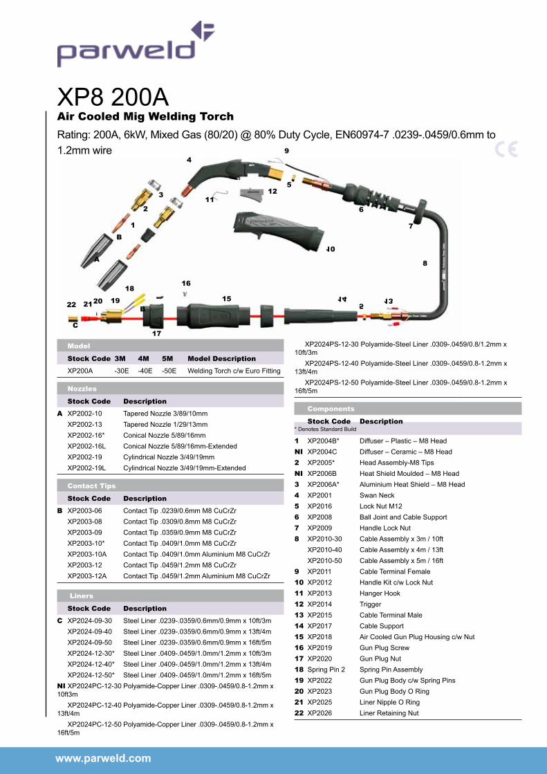
XP8 200AAir Cooled Mig Welding TorchRating: 200A, 6kW, Mixed Gas (80/20) @ 80% Duty Cycle, EN60974-7 .0239-.0459/0.6mm to 1.2mm wire
A
B
1
2
3
4
5
6
7
8
9
10
1112
14 13515
16
17
18
19202122
C
Model
Stock Code 3M 4M 5M Model Description
XP200A -30E -40E -50E Welding Torch c/w Euro Fitting
Nozzles
Stock Code Description
A XP2002-10 Tapered Nozzle 3/89/10mm XP2002-13 Tapered Nozzle 1/29/13mm XP2002-16* Conical Nozzle 5/89/16mm XP2002-16L Conical Nozzle 5/89/16mm-Extended XP2002-19 Cylindrical Nozzle 3/49/19mm XP2002-19L Cylindrical Nozzle 3/49/19mm-Extended
Contact Tips
Stock Code Description
B XP2003-06 Contact Tip .0239/0.6mm M8 CuCrZr XP2003-08 Contact Tip .0309/0.8mm M8 CuCrZr XP2003-09 Contact Tip .0359/0.9mm M8 CuCrZr XP2003-10* Contact Tip .0409/1.0mm M8 CuCrZr XP2003-10A Contact Tip .0409/1.0mm Aluminium M8 CuCrZr XP2003-12 Contact Tip .0459/1.2mm M8 CuCrZr XP2003-12A Contact Tip .0459/1.2mm Aluminium M8 CuCrZr
Liners
Stock Code Description
C XP2024-09-30 Steel Liner .0239-.0359/0.6mm/0.9mm x 10ft/3m XP2024-09-40 Steel Liner .0239-.0359/0.6mm/0.9mm x 13ft/4m XP2024-09-50 Steel Liner .0239-.0359/0.6mm/0.9mm x 16ft/5m XP2024-12-30* Steel Liner .0409-.0459/1.0mm/1.2mm x 10ft/3m XP2024-12-40* Steel Liner .0409-.0459/1.0mm/1.2mm x 13ft/4m XP2024-12-50* Steel Liner .0409-.0459/1.0mm/1.2mm x 16ft/5mNI XP2024PC-12-30 Polyamide-Copper Liner .0309-.0459/0.8-1.2mm x 10ft3m XP2024PC-12-40 Polyamide-Copper Liner .0309-.0459/0.8-1.2mm x 13ft/4m XP2024PC-12-50 Polyamide-Copper Liner .0309-.0459/0.8-1.2mm x 16ft/5m
XP2024PS-12-30 Polyamide-Steel Liner .0309-.0459/0.8/1.2mm x 10ft/3m XP2024PS-12-40 Polyamide-Steel Liner .0309-.0459/0.8-1.2mm x 13ft/4m XP2024PS-12-50 Polyamide-Steel Liner .0309-.0459/0.8-1.2mm x 16ft/5m
Components
Stock Code Description * Denotes Standard Build
1 XP2004B* Diffuser – Plastic – M8 HeadNI XP2004C Diffuser – Ceramic – M8 Head2 XP2005* Head Assembly-M8 TipsNI XP2006B Heat Shield Moulded – M8 Head3 XP2006A* Aluminium Heat Shield – M8 Head4 XP2001 Swan Neck5 XP2016 Lock Nut M126 XP2008 Ball Joint and Cable Support7 XP2009 Handle Lock Nut8 XP2010-30 Cable Assembly x 3m / 10ft XP2010-40 Cable Assembly x 4m / 13ft XP2010-50 Cable Assembly x 5m / 16ft9 XP2011 Cable Terminal Female10 XP2012 Handle Kit c/w Lock Nut11 XP2013 Hanger Hook12 XP2014 Trigger13 XP2015 Cable Terminal Male14 XP2017 Cable Support15 XP2018 Air Cooled Gun Plug Housing c/w Nut16 XP2019 Gun Plug Screw17 XP2020 Gun Plug Nut18 Spring Pin 2 Spring Pin Assembly19 XP2022 Gun Plug Body c/w Spring Pins20 XP2023 Gun Plug Body O Ring21 XP2025 Liner Nipple O Ring22 XP2026 Liner Retaining Nut
B

www.parweld.com www.parweld.com
Everyday Gas Regulators – 300 BAR Single StageFeaturesFlow rate up to 96m3/h (3389 ft3/h)• Full 300 bar capability• Outlet pressure indicated on the bonnet
• Bottom entry design suited for top outlet cylinder valves
Fittings• Fitted with standard 3/89 BSP outlet• Fitted with 5/89 BSP inlet connections
Stock Code Description Maximum Outlet Pressure
E700140 Argon Preset Regulator 3.0 Bar
E700141 Argon Indicator Regulator 3.0 Bar
E700113 1 Gauge Argon 30 lpm flow
E700123 2 Gauge Argon 30 lpm flow
Flow MetersFeatures• Designed from brass bar whilst the
tube and cover are moulded from high quality polycarbonate to ensure high impact resistance and clarity
• Calibrated to operate at an inlet pressure of 30PSI
• Sensitive needle valve provides easy adjustment and the downward facing outlet connection eliminates hose kinking.
Fittings
• Fitted with standard 3/89 BSP inlet and outlet connections Stock Code Description
706101 Flow Meter Mixed Gas 25 lpm (MIG)
8.0 accessories8.2 torch spares
8.3 Gas equipment
Gas flow Tester
• Designed to check gas flow at the front of Mig Torches.
Stock Code Description
806001 Gas flow Tester
www.parweld.com
16
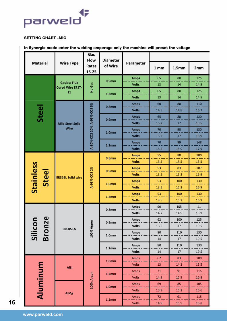
SETTING CHART -MIG
In Synergic mode enter the welding amperage only the machine will preset the voltage
Amps 65 80 125 150 160 200 220 249
Volts 13 14 14.5 18.5 21 24 24.9 25.1
Amps 65 80 125 150 160 200 220 249
Volts 13 14 14.5 18.5 24 25 26 27.1
Amps 60 80 110 140 160 180 200 250
Volts 14.5 14.8 16.7 18 19.7 22.3 24.5 28.5
Amps 65 80 120 155 180 200 220 250
Volts 15.2 17 19.5 20.1 23.1 23 24.5 28.5
Amps 70 90 130 140 199 220 240 250
Volts 15.2 17 18.9 20.1 21.9 24.5 26.5 28.5
Amps 70 99 148 159 200 225 239 245
Volts 15.5 15.9 17.9 18.5 21.9 24.9 26 27.1
Amps 55 80 100 122 145 150 190 200
Volts 13.5 15.5 13.5 19.2 20.7 22.5 22.9 23.5
Amps 53 83 107 148 165 200 210 220
Volts 13.5 15.2 16.9 20 22.1 22.5 23.5 23.5
Amps 53 100 130 160 180 200 215 225
Volts 13.5 15.2 16.9 20.5 21.1 22.5 23.5 23.9
Amps 53 100 130 160 180 200 220 240
Volts 13.5 15.2 16.9 20.5 21.1 22.5 23.5 24.1
Amps 90 105 11 140 146 166 180 200
Volts 14.7 14.9 15.9 17 17.9 19.3 21.5 23.5
Amps 62 100 125 155 170 200 185 205
Volts 13.5 17 19.5 20.3 20.1 23.5 21.5 23.5
Amps 80 110 130 140 170 200 189 210
Volts 14 17 19.5 20.3 20.1 23.1 22.1 23.5
Amps 80 110 130 140 170 200 195 220
Volts 14 17 19.5 20.3 20.1 23.5 22.5 24.5
Amps 62 83 100 120 146 160 190 210
Volts 13 14.2 15.5 16.5 19.9 22.5 23.8 24.8
Amps 71 91 115 128 140 160 195 210
Volts 14.9 15.9 16.8 17.9 19.9 22.5 24.8 24.8
Amps 69 85 105 125 140 160 195 210
Volts 13.9 15.2 16.6 16.9 19.9 22.5 24.8 24.8
Amps 72 91 115 128 140 160 195 210
Volts 14.9 15.9 16.8 17.9 19.9 22.5 24.8 24.8
Silic
on
Bron
ze
100%
Arg
on 0.9mm
1.0mm
1.2mm
1.2mm
1.0mm
1.2mm
1.0mm
100%
Arg
on
0.8mm
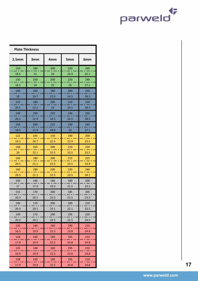
Material Wire TypeDiameter of Wire
No
Gas
0.9mm
Stee
l
1.2mm
Mild Steel Solid Wire
0.8mm
0.9mm
1.0mm
1.2mm
Gasless Flux Cored Wire E71T-
11
Gas Flow Rates 15-25
Stai
nles
s St
eel
ER316L Solid wire
AlSi
Alum
inum
AlMg
ERCuSI-A
Parameter
Ar98
%-C
O2
2%Ar
80%
-CO
2 20
% A
r95%
-CO
2 5%
Plate Thickness
1 mm 1.5mm 2mm 2.5mm 3mm 4mm 5mm 6mm
0.8mm
0.9mm
1.0mm
1.2mm
www.parweld.com www.parweld.com
17
SETTING CHART -MIG
In Synergic mode enter the welding amperage only the machine will preset the voltage
Amps 65 80 125 150 160 200 220 249
Volts 13 14 14.5 18.5 21 24 24.9 25.1
Amps 65 80 125 150 160 200 220 249
Volts 13 14 14.5 18.5 24 25 26 27.1
Amps 60 80 110 140 160 180 200 250
Volts 14.5 14.8 16.7 18 19.7 22.3 24.5 28.5
Amps 65 80 120 155 180 200 220 250
Volts 15.2 17 19.5 20.1 23.1 23 24.5 28.5
Amps 70 90 130 140 199 220 240 250
Volts 15.2 17 18.9 20.1 21.9 24.5 26.5 28.5
Amps 70 99 148 159 200 225 239 245
Volts 15.5 15.9 17.9 18.5 21.9 24.9 26 27.1
Amps 55 80 100 122 145 150 190 200
Volts 13.5 15.5 13.5 19.2 20.7 22.5 22.9 23.5
Amps 53 83 107 148 165 200 210 220
Volts 13.5 15.2 16.9 20 22.1 22.5 23.5 23.5
Amps 53 100 130 160 180 200 215 225
Volts 13.5 15.2 16.9 20.5 21.1 22.5 23.5 23.9
Amps 53 100 130 160 180 200 220 240
Volts 13.5 15.2 16.9 20.5 21.1 22.5 23.5 24.1
Amps 90 105 11 140 146 166 180 200
Volts 14.7 14.9 15.9 17 17.9 19.3 21.5 23.5
Amps 62 100 125 155 170 200 185 205
Volts 13.5 17 19.5 20.3 20.1 23.5 21.5 23.5
Amps 80 110 130 140 170 200 189 210
Volts 14 17 19.5 20.3 20.1 23.1 22.1 23.5
Amps 80 110 130 140 170 200 195 220
Volts 14 17 19.5 20.3 20.1 23.5 22.5 24.5
Amps 62 83 100 120 146 160 190 210
Volts 13 14.2 15.5 16.5 19.9 22.5 23.8 24.8
Amps 71 91 115 128 140 160 195 210
Volts 14.9 15.9 16.8 17.9 19.9 22.5 24.8 24.8
Amps 69 85 105 125 140 160 195 210
Volts 13.9 15.2 16.6 16.9 19.9 22.5 24.8 24.8
Amps 72 91 115 128 140 160 195 210
Volts 14.9 15.9 16.8 17.9 19.9 22.5 24.8 24.8
Silic
on
Bron
ze
100%
Arg
on 0.9mm
1.0mm
1.2mm
1.2mm
1.0mm
1.2mm
1.0mm
100%
Arg
on
0.8mm
Material Wire TypeDiameter of Wire
No
Gas
0.9mm
Stee
l
1.2mm
Mild Steel Solid Wire
0.8mm
0.9mm
1.0mm
1.2mm
Gasless Flux Cored Wire E71T-
11
Gas Flow Rates 15-25
Stai
nles
s St
eel
ER316L Solid wire
AlSi
Alum
inum
AlMg
ERCuSI-A
Parameter
Ar98
%-C
O2
2%Ar
80%
-CO
2 20
% A
r95%
-CO
2 5%
Plate Thickness
1 mm 1.5mm 2mm 2.5mm 3mm 4mm 5mm 6mm
0.8mm
0.9mm
1.0mm
1.2mm

9.0 EC declaration of conformity
Hereby we declare that the machines as stated below
Type: XTM182i
Conform to the EC Directives:Low Voltage Directive 2006/95/EC
EMC Directive 2004/108/ECHarmonised European standard: EN/IEC 60974-1
This is to certify that the tested sample is in conformity with all provisions of the above detailed EU directives and product standards.
9.1 Rohs Compliance Declaration
Directive 2011/65/EU of the European Parliament
Restriction of use of certain hazardous substances in electrical and electronic equipment
Type: XTM182i
The above listed products are certified to be compliant with the rohs directive with all homogeneous component parts being controlled to ensure material contents as per the list below.
Cadmium 0.01% by weightLead 0.1% by weight
Mercury 0.1% by weightHexavalent chromium 0.1% by weight
Polybrominated biphenyl’s (pbbs) 0.1% by weightPolybrominated diphenyl ethers (pbdes) 0.1% by weight
It should be noted that under specific exempted applications, where lead is used as an alloying element the following limits are applied in accordance with the regulations.
Copper and copper alloy parts use less than 4% by weight of each homogeneous component.
Steel and steel alloy parts use less than 4% by weight of each homogeneous component.
Aluminium and aluminium alloy parts use less than 4% by weight of each homogeneous component.
www.parweld.com
18
Only dispose off in authorised sites for electrical and electronic waste do not dispose of with general refuse or landfill waste.
www.parweld.com
19
9.2 WEEE Statement
WEEE (Waste Electrical & Electronic Equipment) 2002/96/EC In relation to implementing the legislation, Parweld has established relevant recycling and recovery methods. We have been fully compliant against the marking requirements since August 2005. Parweld is registered in the UK with the Environment agency as detailed below. For WEE compliance outside the UK please contact your supplier/ImporterParweld is registered with a compliance scheme Official registration number is WEE/FD0255QV
When your equipment reaches the end of its service life you should return it to Parweld where it will be reconditioned or processed for recycling.
9.3 Statement of warranty
Limited Warranty: Parweld Ltd, hereafter, “Parweld” warrants its customers that its products will be free of defects in workmanship or material. Should any failure to conform to this warranty appear within the time period applicable to the Parweld products as stated below, Parweld shall, upon notification thereof and substantiation that the product has been stored, installed, operated, and maintained in accordance with Parweld’s specifications, instructions, recommendations and recognized standard industry practice, and not subject to misuse, repair, neglect, alteration, or accident, correct such defects by suitable repair or replacement, at Parweld’s sole option, of any components or parts of the product determined by Parweld to be defective.
Parweld makes no other warranty, express or implied. This warranty is exclusive and in lieu of all others, including, but not limited to any warranty of merchantability or fitness for any particular purpose.
Limitation of Liability: Parweld shall not under any circumstances be liable for special, indirect or consequential damages, such as, but not limited to, lost profits and business interruption. The remedies of the purchaser set forth herein are exclusive and the liability of Parweld with respect to any contract, or anything done in connection therewith such as the performance or breach thereof, or from the manufacture, sale, delivery, resale, or use of any goods covered by or furnished by Parweld whether arising out of contract, negligence, strict tort, or under any warranty, or otherwise, shall not, except as expressly provided herein, exceed the price of the goods upon which such liability is based. No employee, agent, or representative of Parweld is authorized to change this warranty in any way or grant any other warranty.
Purchaser’s rights under this warranty are void if replacement parts or accessories are used which in Parweld’s sole judgement may impair the safety or performance of any Parweld product.
Purchaser’s rights under this warranty are void if the product is sold to purchaser by non-authorized persons.
The warranty is effective for the time stated below beginning on the date that the authorized Distributor delivers the products to the purchaser. Notwithstanding the foregoing, in no event shall the warranty period extend more than the time stated plus one month from the date Parweld delivered the product to the authorized distributor.
Main Transformers and Rectifiers 2 Years
Other machine parts 2 year

Parweld LimitedBewdley Business Park
Long BankBewdley
WorcestershireEngland
DY12 2TZ
tel. +44 1299 266800fax. +44 1299 266900


