28
ZCU102 Board Interface Test February 2019 XTP428

ZCU102 Board Interface Test
February 2019
XTP428

© Copyright 2019 Xilinx, Inc. Xilinx, the Xilinx logo, Artix, ISE, Kintex, Spartan, Virtex, Vivado, Zynq, and other designated brands included herein are trademarks of Xilinx in the United States and other countries. All other trademarks are the property of their respective owners. NOTICE OF DISCLAIMER: The information disclosed to you hereunder (the “Information”) is provided “AS-IS” with no warranty of any kind, express or implied. Xilinx does not assume any liability arising from your use of the Information. You are responsible for obtaining any rights you may require for your use of this Information. Xilinx reserves the right to make changes, at any time, to the Information without notice and at its sole discretion. Xilinx assumes no obligation to correct any errors contained in the Information or to advise you of any corrections or updates. Xilinx expressly disclaims any liability in connection with technical support or assistance that may be provided to you in connection with the Information. XILINX MAKES NO OTHER WARRANTIES, WHETHER EXPRESS, IMPLIED, OR STATUTORY, REGARDING THE INFORMATION, INCLUDING ANY WARRANTIES OF MERCHANTABILITY, FITNESS FOR A PARTICULAR PURPOSE, OR NONINFRINGEMENT OF THIRD-PARTY RIGHTS.
Revision History Date Version Description 02/25/19 10.1 Updated document format.
12/05/18 10.0 Updated for 2018.3. Updated to work with both MTA8 and MTA4 SODIMMs.
06/18/18 9.0 Updated for 2018.2.
04/09/18 8.0 Updated for 2018.1.
12/20/17 7.0 Updated for 2017.4
10/09/17 6.0 Updated for 2017.3.
06/20/17 5.0 Updated for 2017.2.
04/19/17 4.0 Updated for 2017.1.
12/19/16 3.0 Updated for 2016.4.
10/13/16 2.0 Updated for 2016.3
05/27/15 1.0 Initial version.

ZCU102 Board Interface Test Overview ˃ ZCU102 Software Install and Board Setup ˃ ZCU102 Board Interface Test Setup ˃ Board Interface Test ˃ Appendix ˃ References
Note: This presentation applies to the ZCU102

Xilinx ZCU102 Board

ZCU102 Software Install and Board Setup ˃ Refer to XTP435 – ZCU102 Software Install and Board Setup for details on:
Software Requirements ZCU102 Board Setup UART Driver Install Clock Setup Ethernet Setup
Note: Presentation applies to the ZCU102
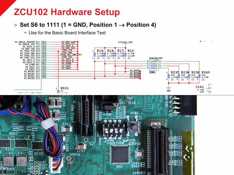
ZCU102 Hardware Setup ˃ Set S6 to 1111 (1 = GND, Position 1 → Position 4)
Use for the Basic Board Interface Test

ZCU102 Board Interface Test Setup ˃ Open the RDF0377 – ZCU102 Board Interface Test Files (2018.3 C) ZIP file
Extract these files to your C:\ drive
Note: Presentation applies to the ZCU102

Basic Board Interface Test ˃ From C:\zcu102_bit, double click on BoardUI.exe
Note: Executable requires 64-bit Windows

Basic Board Interface Test ˃ Enter the Board Serial Number and Mac Address and click OK
Note: Presentation applies to the ZCU102

Basic Board Interface Test ˃ Click the Run All button
Note: Presentation applies to the ZCU102

Basic Board Interface Test ˃ All selected tests passed
Note: Presentation applies to the ZCU102
Notes ˃ Ensure that you have followed all instructions in XTP435, ZCU102 Software
Install and Board Setup ˃ Ensure that no other Terminal program is connected to the ZCU102’s four
COM ports while the Board Interface Test is running See XTP435, for details on COM Ports
˃ Only one board can be connected to your PC during the test Both USB UART (J83) and USB JTAG (J2) are required for this test Disconnect any other board UARTs or Programming Cables
˃ If you missed any set-up instructions and experience problems, then please follow these steps:
Recheck your setup End any hw_server processes and cycle board power Open Vivado Hardware Manager and test PC-board JTAG connectivity
Note: Presentation applies to the ZCU102

Appendix
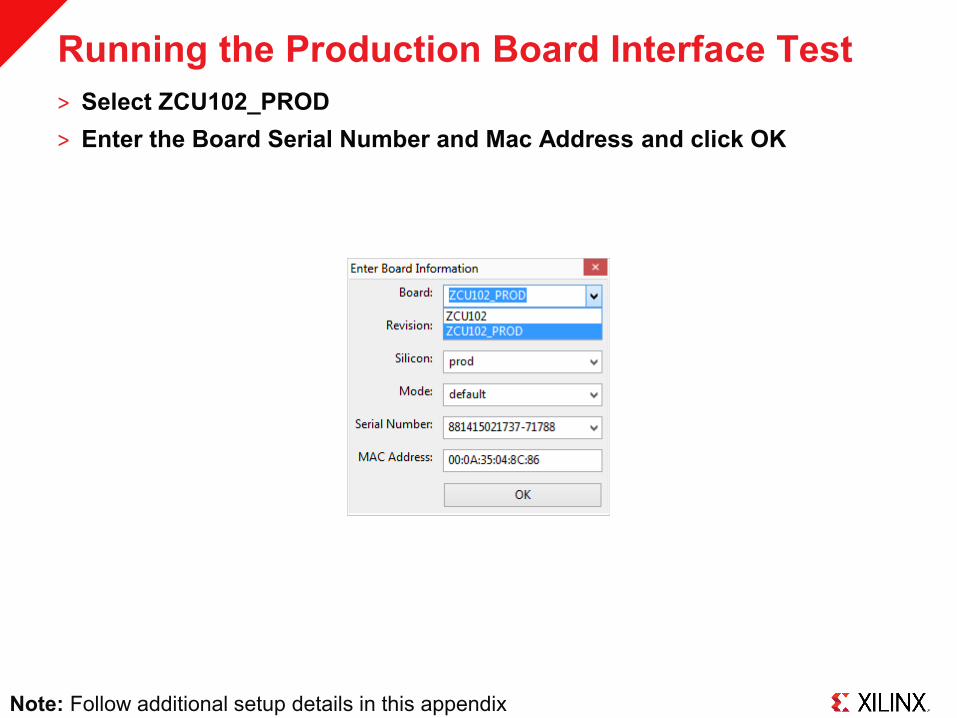
Running the Production Board Interface Test ˃ Select ZCU102_PROD ˃ Enter the Board Serial Number and Mac Address and click OK
Note: Follow additional setup details in this appendix
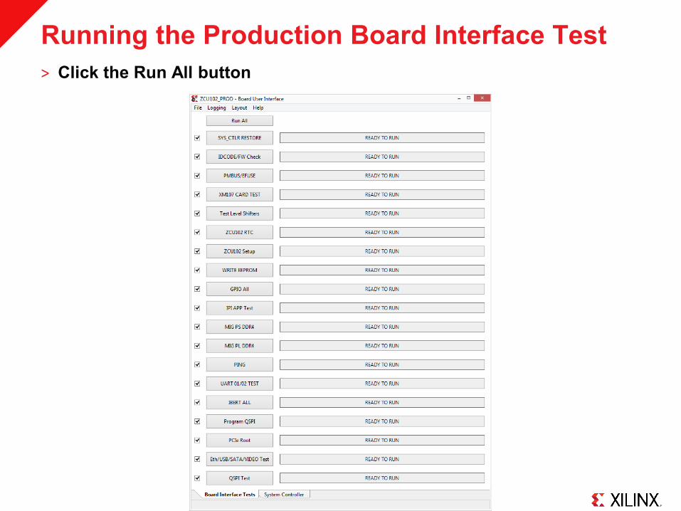
Running the Production Board Interface Test ˃ Click the Run All button

Running the Production Board Interface Test ˃ All selected tests passed

Test Details ˃ Review the following pages to make sure the board is set up for the
Production Board Interface Test ˃ Ensure that no other Terminal program is connected to the ZCU102’s COM
ports while the Board Interface Test is running See XTP497, for details on COM Ports
˃ Only one board can be connected to your PC during the test Disconnect any other board UARTs or Programming Cables
˃ If you missed any set-up instructions and experience problems, then please follow these steps:
Recheck your setup End any hw_server processes and cycle board power Open Vivado Hardware Manager and test PC-board JTAG connectivity
Note: Presentation applies to the ZCU102

Optional Test Equipment ˃ This test requires optional equipment
2ea Whizz FMC XM107 boards ‒ Attach to HPC0 (J5) and HPC1 (J4)
4k HDMI source; tested with NVIDIA 4K Shield ‒ Attach Source to bottom port of P7
HDMI and DP monitors plus cables ‒ Tested with LG 27MU67-B monitor ‒ Attach HDMI monitor to top port of P7 ‒ Attach DP monitor to P11
USB Thumb drive; tested with SDCZ43 32GB USB Mouse ‒ Use included USB adapter with both Mouse and Thumb drive
A generic SATA Flash drive; formatted Win95 FAT32 (LBA) ‒ Use ATX Power, J10 on ZCU102 to power SATA Drive ‒ Connect SATA cable to P9
An SD card, programmed with the contents of HDMI_Input PCIe test board – Use a KCU105 or VCU108 with bitstreams/MCS files included in pcie_bitstreams directory
Note: Presentation applies to the ZCU102

Optional Test Equipment ˃ This test requires optional equipment
Frequency Source @ 148.5 MHz ‒ Setup shown on following pages
Shunt jumpers on PMODs ‒ J55: Suggested MNT-102-BK-G and S2021EC-06-ND;
combined as shown to the rightmost ‒ J87: MNT-102-BK-G as shown to the leftmost
Jumpers on PROTO Header ‒ Connect pins 6 to 8, 10 to 12, 14 to 16, 18 to 20, and 22 to 24
Jumpers for System Controller Programming ‒ Follow instructions in BIT GUI
Mictor Loopback adapter, see setup on following pages
Note: Presentation applies to the ZCU102

Optional Test Equipment ˃ This test requires optional equipment
SFP Loopback Adapters ‒ www.molex.com ‒ SFP Loopback Adapter,
5.0 db Attenuation ‒ Part # 74765-0904
The ZCU102 uses 4 adapters
Note: Presentation applies to the ZCU102

SMA Cable Setup ˃ Four SMA Cables
www.rosenbergerna.com Part number: 72D-32S1-32S1-00610A
˃ Optional: SMA Quick connects RADIALL Part number: R125791501 Available here or here
Note: Presentation applies to the ZCU102

Optional Hardware Setup ˃ Hook up the SMA cables as shown ˃ IBERT Test:
J70 to J72 (Red) J69 to J71 (Yellow)
˃ IPI Clocking Test Connect J79 and J80 (Green) to a 148.5 MHz clock source
Note: Presentation applies to the ZCU102

ZCU102 Mictor Loopback Adapter Setup ˃ Mictor Loopback Test
www.zebax.com Mictor Breakout Adapter Plug Part # ZX104LN
˃ Mictor Jumper odd side as follows: 7 to 11 9 to 13 15 to 19 17 to 21 23 to 27 25 to 29 31 to 35 33 to 37
Note: Presentation applies to the ZCU102

ZCU102 Mictor Loopback Adapter Setup ˃ Mictor Jumper even side (not shown) as follows:
6 to 8 10 to 16 (use a wire) 16 to 20 22 to 24 26 to 28 36 to 38 (use a wire)
˃ Insert into Mictor slot P6 Make sure they are firmly inserted
Note: Presentation applies to the ZCU102

References

References ˃ Vivado Release Notes
Vivado Design Suite User Guide - Release Notes – UG973 ‒ https://www.xilinx.com/support/documentation/sw_manuals/xilinx2018_3/
ug973-vivado-release-notes-install-license.pdf Vivado Design Suite 2018 - Vivado Known Issues ‒ https://www.xilinx.com/support/answers/70860.html
˃ Vivado Programming and Debugging Vivado Design Suite Programming and Debugging User Guide – UG908 ‒ http://www.xilinx.com/support/documentation/sw_manuals/xilinx2018_3/
ug908-vivado-programming-debugging.pdf

Documentation

Documentation ˃ Zynq UltraScale+
Zynq UltraScale+ MPSoC ‒ http://www.xilinx.com/products/silicon-devices/soc/zynq-ultrascale-mpsoc.html
˃ ZCU102 Documentation Xilinx Zynq UltraScale+ MPSoC ZCU102 Evaluation Kit ‒ https://www.xilinx.com/products/boards-and-kits/ek-u1-zcu102-g.html
ZCU102 Board User Guide – UG1182 ‒ https://www.xilinx.com/support/documentation/boards_and_kits/zcu102/
ug1182-zcu102-eval-bd.pdf ZCU102 Evaluation Kit Quick Start Guide User Guide – XTP426 ‒ https://www.xilinx.com/support/documentation/boards_and_kits/zcu102/
xtp426-zcu102-quickstart.pdf ZCU102 - Known Issues Master Answer Record ‒ https://www.xilinx.com/support/answers/66752.html


