44
Installation Guide OSD MENU GUIDE
| Date post: | 09-Apr-2019 |
| Category: |
Documents |
| Upload: | truongkhanh |
| View: | 215 times |
| Download: | 0 times |

Installation Guide
OSD MENU GUIDE
1. General Cautions
1
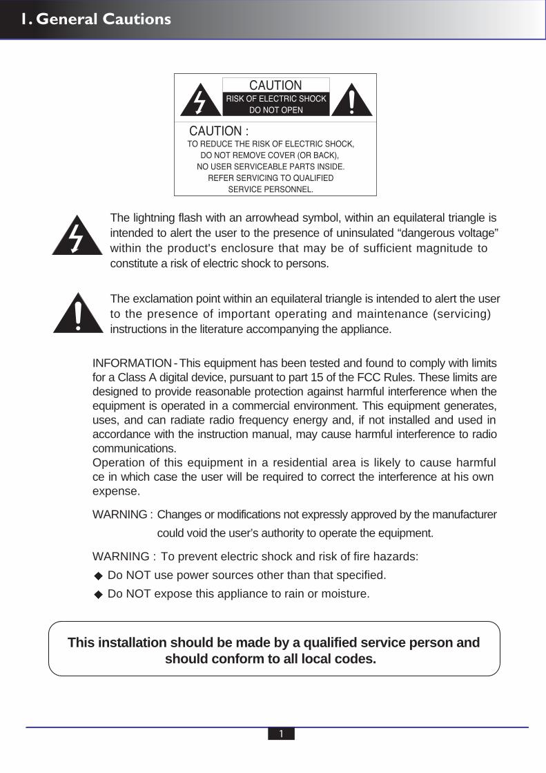
This installation should be made by a qualified service person and should conform to all local codes.
The lightning flash with an arrowhead symbol, within an equilateral triangle isintended to alert the user to the presence of uninsulated “dangerous voltage”within the product's enclosure that may be of sufficient magnitude toconstitute a risk of electric shock to persons.
The exclamation point within an equilateral triangle is intended to alert the userto the presence of important operating and maintenance (servicing)instructions in the literature accompanying the appliance.
INFORMATION-This equipment has been tested and found to comply with limitsfor a Class A digital device, pursuant to part 15 of the FCC Rules. These limits aredesigned to provide reasonable protection against harmful interference when theequipment is operated in a commercial environment. This equipment generates,uses, and can radiate radio frequency energy and, if not installed and used inaccordance with the instruction manual, may cause harmful interference to radiocommunications.Operation of this equipment in a residential area is likely to cause harmfulce in which case the user will be required to correct the interference at his ownexpense.
WARNING : Changes or modifications not expressly approved by the manufacturercould void the user’s authority to operate the equipment.
WARNING : To prevent electric shock and risk of fire hazards:Do NOT use power sources other than that specified.Do NOT expose this appliance to rain or moisture.
Table of Contents
2
Table of Contents
General Cautions
General Features
Precautions
Main Menu
Exit
CAMERA SET
Intelligence
Privacy Zone Other Set
Communication System Info Language
CAMERA ID IRIS MOTION
SENS-UP FLICKERLESS DIS DAY / NIGHT WHITE BAL DIGITAL ZOOM DETAIL V-SYNC AGC COLOR SUP REVERSE POSI / NEGA PIP
MOTION MASK AREA DISPLAY SENSITIVITY RESOLUTION ALARM OUT
FACTORY DEFAULTS OSD COLOR
DNR SHUTTER
1
2
3
4
7
Safety Instructions 6
8911151617171819202224252626272728
29303232333334
3737
40
Factory Defaults 41
Trouble Shooting 42
37
38
39
3. General Features
1/3” 470K SONY SUPER HAD CCD Minimum illumination 0.00006 Lux(Sens-Up On) S/N Ratio 52dB
High Resolution of 600 TV Lines(Colour) and 700 TV Lines(B/W) This camera has realized high resolution of 600TV lines and 700TV lines using the top-notch full digital image processing, 12 Bit A/D serial signal processing and special algorithm technologies.
DNR(Digial Noise Reduction, 2D + 3D) The DNR technology eliminates noise thus generating a distinct and clear image. The function of DNR utilizes both an adaptive 2D filter reducing noise in the brightness of the image and an adaptive 3D filter reducing noise caused by movement.
DAY & NIGHT(Output the filter changing signal) The function of DAY/NIGHT has outputs the filter changing signal with detecting the illumination condition. DAY & NIGHT operation feature an “AUTO” mode which switchs between day & night mode automatically based upon the level of illumination of the scene.
Privacy Mask Function(Polygnal method, 4 points) Privacy masking allows for the ‘blanking’ for the specific areas of a scene, where the viewing or recording of image is prohibited or undesired. The technology of privacy masking function allows for the user defined setting of a four points polygonal mask, which is overlaid onto the video signal output.
OSD(On Screen Display) This camera supports the OSD function which is used with multi-language. The camera can be controlled by selecting user’s desired mode on the monitor screen.
CCVC(Camera Control Via Coaxial cable ) This camera can be controlled by remote controller that overlabs the coaxial cable ( for a transfer of the video signal ) with the control signal. During installation or reset the osd menu, this helps you control the communication controller (optional) without additional cabling. Coaxial Remote Controller - Option
3
4. Precautions
4
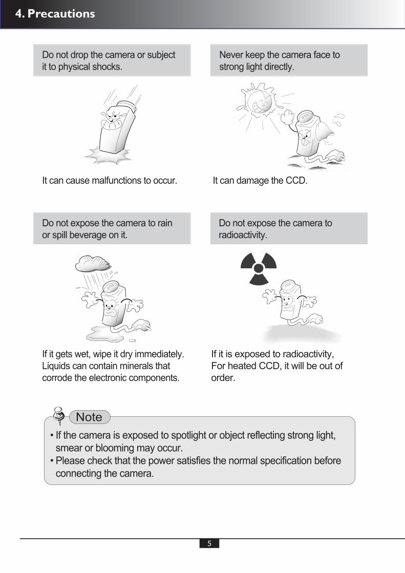
4. Precautions
5
5. Safety Instructions
6
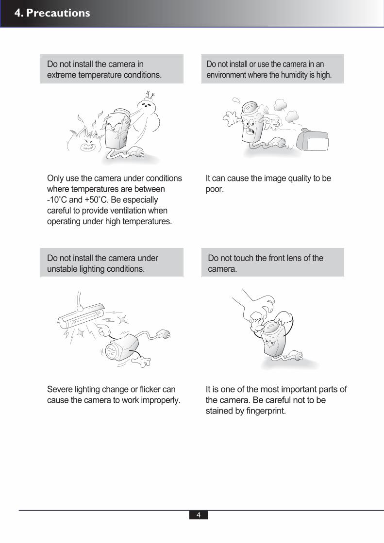
Precautions for UsePrecautions for Use
Please read this manual throughly before using this camera to become familiar with the correct operation procedures.
Keep the camera box and packing in case the product needs to be returned.
Do not open the camera body and touch any electrical parts to avoid possible electric shocks.
Do not install the camera in a position facing directly at a strong light source.
Do not install or use the camera in areas of high humidity.
Do not install near any cooling or heating equipment. Do not install the camera in dusty environments.
Do not install the camera in places where the camera is subjected to physical shocks.
Only apply power after installation of the product.
Do not insert objects into the camera body to prevent fire hazards and electric shock.
Do not touch the camera with wet hands to avoid electric shock.
Do not disconnect the power cord from a power plug when still connected to the outlet.
Always disconnect the power by removing the plug from the power socket.
lf the camera emits a burning smell, immediately disconnect it from the power source and report the problem to your distributor where you have purchased it.
WarrantyWarranty
Cautions When UsingCautions When Using
Cautions When InstallCautions When Install
This camera is supplied with a two year warranty effective from the day of purchase on a return to base basis(RTB). Our standard Returns Procedure needs to be followed for warranty repairs.
This products must be used with a regulated DC 12V or AC 24V adaptor for power.
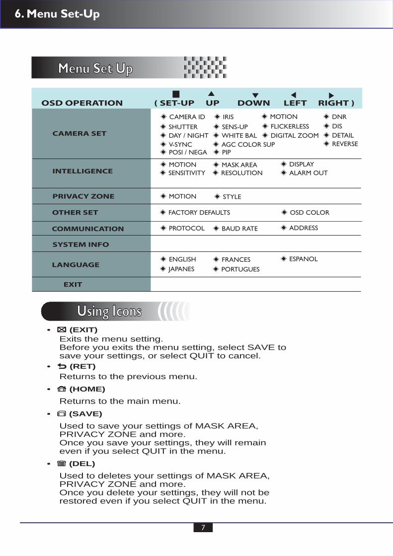
6. Menu Set-Up
7
CAMERA SET
INTELLIGENCE
PRIVACY ZONE
OTHER SET
COMMUNICATION
SYSTEM INFO
LANGUAGE
EXIT
OSD OPERATION ( SET-UP UP DOWN LEFT RIGHT )
CAMERA ID IRIS MOTION
SENS-UP FLICKERLESS DIS DAY / NIGHT WHITE BAL DIGITAL ZOOM DETAIL V-SYNC AGC COLOR SUP REVERSE POSI / NEGA PIP
MOTION
MOTION STYLE
MASK AREA DISPLAY
PROTOCOL BAUD RATE ADDRESS
ENGLISH FRANCES JAPANES PORTUGUES
ESPANOL
SENSITIVITY RESOLUTION ALARM OUT
FACTORY DEFAULTS OSD COLOR
DNR
SHUTTER
Menu Set UpMenu Set Up
Using IconsUsing Icons ((((( (EXIT)
Exits the menu setting. Before you exits the menu setting, select SAVE to save your settings, or select QUIT to cancel.
(RET)Returns to the previous menu.
(HOME)
Returns to the main menu. (SAVE)
Used to save your settings of MASK AREA,PRIVACY ZONE and more.Once you save your settings, they will remain even if you select QUIT in the menu.
(DEL)
Used to deletes your settings of MASK AREA,PRIVACY ZONE and more.Once you delete your settings, they will not berestored even if you select QUIT in the menu.
•
•
•
•
•

6. Menu Set-Up
8
2. Press Down button to select the required function using the Up and Down buttons. Move the status bar to select the desired feature by pressing the Up or Down button.
4. After completing the setting, move the indicator bar to and press the SET button to EXIT.
3. Changing Menu Settings Using the Left or Right buttons. Available values or status are displayed by pressing the Left or Right button. Press the buttons until desired value/status is displayed.
CAMERA SETCAMERA ID OFFIRIS ALCMOTION (F.FAST)---DNR MIDSHUTTER OFFSENS-UP AUTO X4FLICKERLESS OFFDIS OFF
Menu items can be selected by using the OSD buttons on the camera
OSD Main Menu Set Up
1. Press the OSD Set Up button for a second until the OSD displays on screen. The Set Up menu will be displayed on the monitor.
** MAIN MENU **
CAMERA SETINTELLIGENCEPRIVACY ZONEOTHER SETCOMMUNICATION SYSTEM INFO LANGUAGE
Camera SetCamera Set (((((
6. Menu Set-Up
9
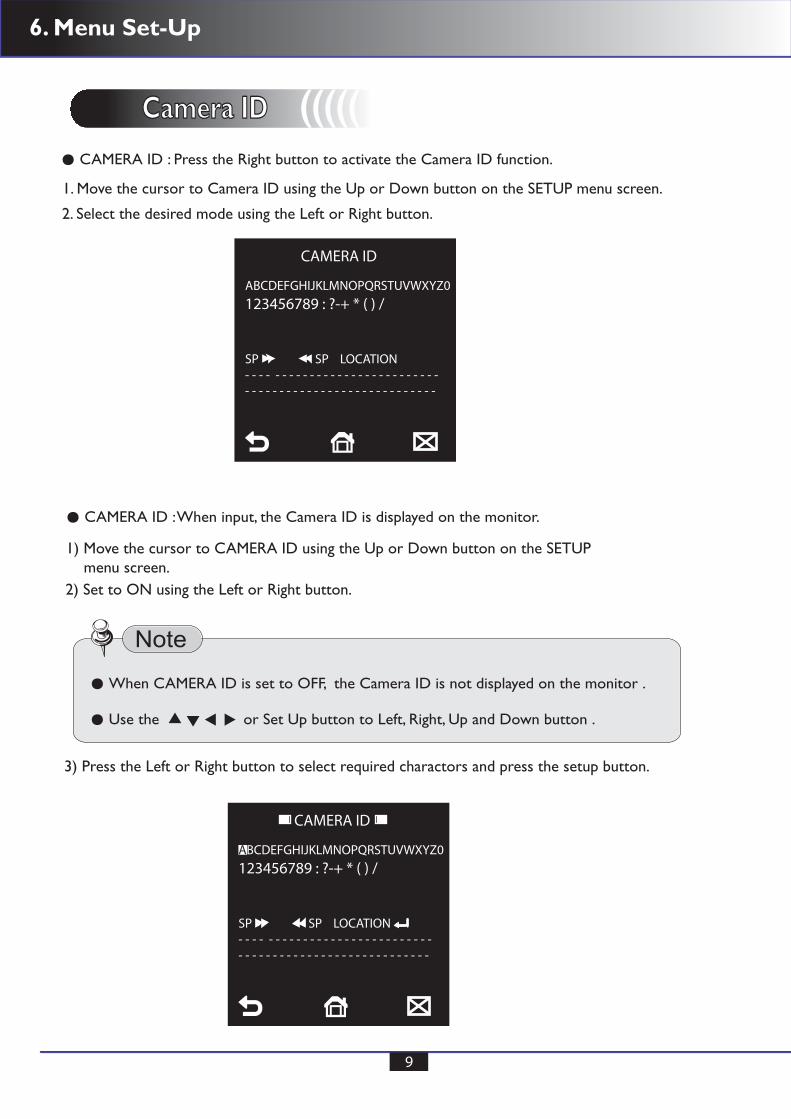
Camera IDCamera ID (((((
CAMERA ID : When input, the Camera ID is displayed on the monitor.
CAMERA ID : Press the Right button to activate the Camera ID function.
1. Move the cursor to Camera ID using the Up or Down button on the SETUP menu screen.
2. Select the desired mode using the Left or Right button.
1) Move the cursor to CAMERA ID using the Up or Down button on the SETUP menu screen.2) Set to ON using the Left or Right button.
3) Press the Left or Right button to select required charactors and press the setup button.
CAMERA ID
ABCDEFGHIJKLMNOPQRSTUVWXYZ0123456789 : ?-+ * ( ) /
SP SP LOCATION- - - - - - - - - - - - - - - - - - - - - - - - - - - -- - - - - - - - - - - - - - - - - - - - - - - - - - - -
CAMERA ID
When CAMERA ID is set to OFF, the Camera ID is not displayed on the monitor .
Use the or Set Up button to Left, Right, Up and Down button .
ABCDEFGHIJKLMNOPQRSTUVWXYZ0123456789 : ?-+ * ( ) /
SP SP LOCATION- - - - - - - - - - - - - - - - - - - - - - - - - - - -- - - - - - - - - - - - - - - - - - - - - - - - - - - -

6. Menu Set-Up
10
Camera IDCamera ID (((((4) The Camera ID can be up to 54 alphanumeric characters in length.
① Move the cursor to choose an alphanumeric character.
5) To select the position where the Camera ID should be displayed on the screen.
① Move the cursor to LOCATION and press the SET button.
② Choose character in the displayed range A~Z, a~z, 0~9 using the Up, Down, Left and Right buttons.
③ Select the desired character by pressing the SETUP button.
④ Repeat the above steps until the Camera ID has been created.
The cursor moves to the next position after character input, by pressing the SETUP button.
CAMERA ID
ABCDEFGHIJKLMNOPQRSTUVWXYZ0123456789 : ?-+ * ( ) /
SP SP LOCATIONA - - - - - - - - - - - - - - - - - - - - - - - - - - -- - - - - - - - - - - - - - - - - - - - - - - - - - - - -
or Set Up button to Left, Right, Up, Down button
In cases where the wrong Camera ID has been input........
Move the cursor onto the wrong charactor and press the setup button to input correctcharacters again by using the and repeat the above steps to input the characters again.
CAM1② Created camera ID is displayed.
③ Select a new position by using the four directional buttons, Press the SET button to confirm the position.
6) Move the cursor to and press the SET button after completing the above process.

6. Menu Set-Up
11
IRIS IRIS (((((
ALC (Automatic Light Control)
① Press the Set Up button to select ALC mode.
②
1) Move the cursor to IRIS and press the Right button to select ALC or ELC adjustment. The IRIS menu is used when required to adjust the intensity of radiation incoming to the camera.
CAMERA SETCAMERA ID OFFIRIS ALCMOTION (F.FAST)---DNR MIDSHUTTER OFFSENS-UP AUTO X4FLICKERLESS OFFDIS OFF
Set the desired lens type by pressing the Right button.
ALC
DC : DC Auto Iris Lens
When DC is selected, the brightness can be adjusted. the brightness controlrange is -32 ~ +32.
Select Video for Video type lens.
LENS DCLEVEL ( 00) ----- I -----BACKLIGHT BLCAREA CENTER
6. Menu Set-Up
12
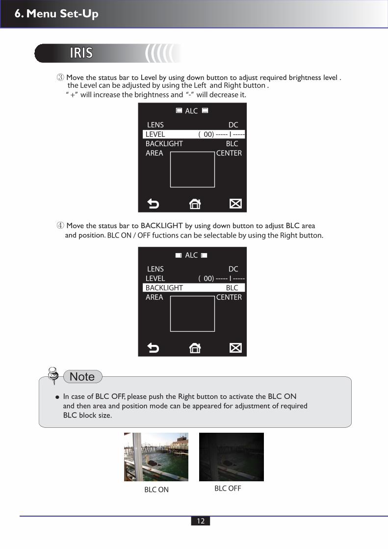
IRIS IRIS ((((( Move the status bar to Level by using down button to adjust required brightness level .
ALC
LENS DCLEVEL ( 00) ----- I -----BACKLIGHT BLCAREA CENTER
ALC
LENS DCLEVEL ( 00) ----- I -----BACKLIGHT BLCAREA CENTER
③ the Level can be adjusted by using the Left and Right button .“ +” will increase the brightness and “-” will decrease it.
④ Move the status bar to BACKLIGHT by using down button to adjust BLC area and position. BLC ON / OFF fuctions can be selectable by using the Right button.
In case of BLC OFF, please push the Right button to activate the BLC ONand then area and position mode can be appeared for adjustment of requiredBLC block size.
BLC ON BLC OFF
6. Menu Set-Up
13
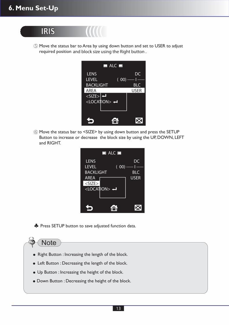
IRIS IRIS ((((( Move the status bar to Area by using down button and set to USER to adjust required position
Move the status bar to <SIZE> by using down button and press the SETUP Button to increase or decrease the block size by using the UP, DOWN, LEFT and RIGHT.
ALC
LENS DCLEVEL ( 00) ----- I -----BACKLIGHT BLCAREA USER<SIZE><LOCATION>
and block size using the Right button .
ALC
LENS DCLEVEL ( 00) ----- I -----BACKLIGHT BLCAREA USER<SIZE><LOCATION>
⑤
⑥
Right Button : Increasing the length of the block.
Press SETUP button to save adjusted function data.
Left Button : Decreasing the length of the block.
Up Button : Increasing the height of the block.
Down Button : Decreasing the height of the block.
♣
6. Menu Set-Up
14
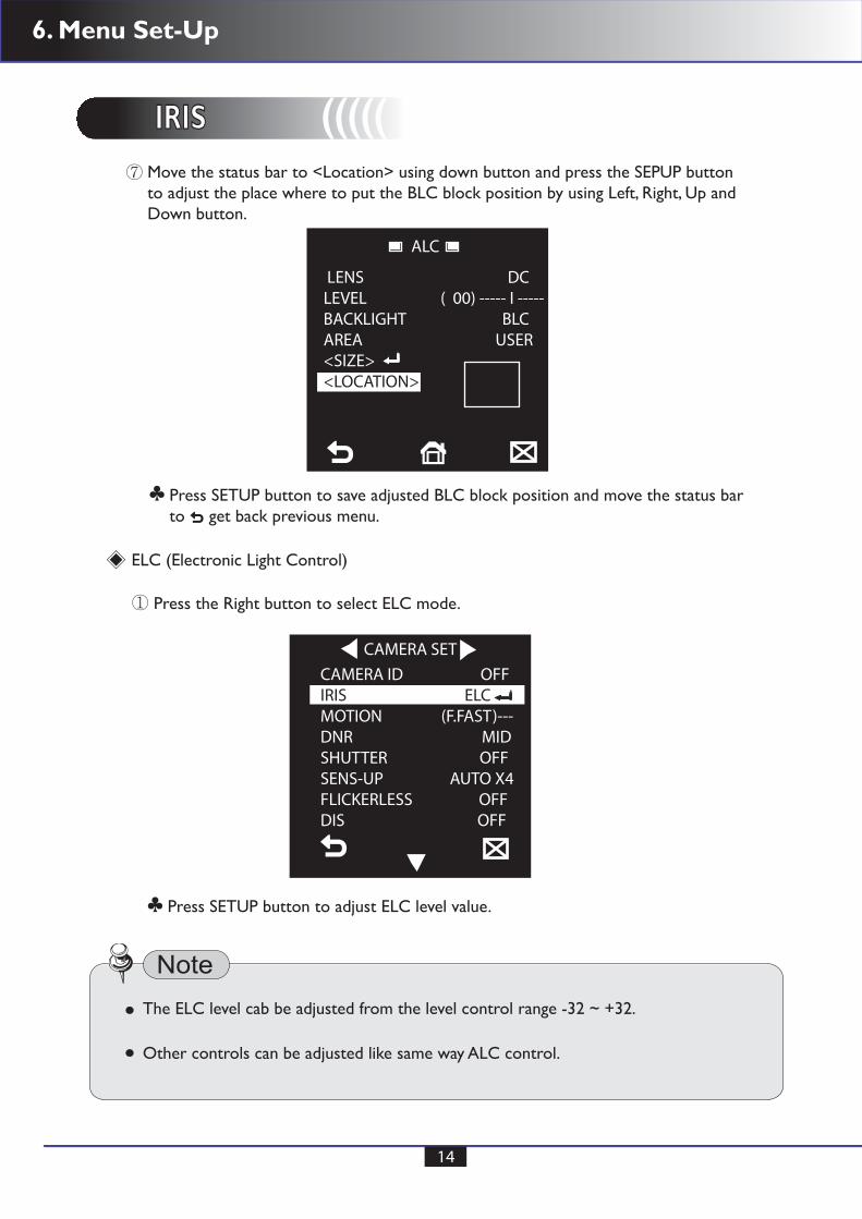
IRIS IRIS ((((( Move the status bar to <Location> using down button and press the SEPUP button to adjust the place where to put the BLC block position by using Left, Right, Up and Down button.
ALC
LENS DCLEVEL ( 00) ----- I -----BACKLIGHT BLCAREA USER<SIZE><LOCATION>
⑦
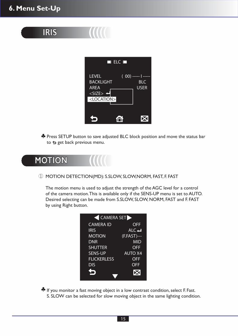
Press SETUP button to save adjusted BLC block position and move the status barto get back previous menu.
♣
Press SETUP button to adjust ELC level value.♣
ELC (Electronic Light Control)
CAMERA SET
CAMERA ID OFFIRIS ELCMOTION (F.FAST)---DNR MIDSHUTTER OFFSENS-UP AUTO X4FLICKERLESS OFFDIS OFF
① Press the Right button to select ELC mode.
Other controls can be adjusted like same way ALC control.
The ELC level cab be adjusted from the level control range -32 ~ +32.
6. Menu Set-Up
15
IRIS IRIS (((((
MOTION MOTION (((((
ELC
LEVEL ( 00) ----- I -----BACKLIGHT BLCAREA USER<SIZE><LOCATION>
Press SETUP button to save adjusted BLC block position and move the status barto get back previous menu.
If you monitor a fast moving object in a low contrast condition, select F. Fast.S. SLOW can be selected for slow moving object in the same lighting condition.
♣
♣
MOTION DETECTION(MD): S.SLOW, SLOW,NORM, FAST, F. FAST
The motion menu is used to adjust the strength of the AGC level for a controlof the camera motion. This is available only if the SENS-UP menu is set to AUTO.Desired selecting can be made from S.SLOW, SLOW, NORM, FAST and F. FAST by using Right button.
CAMERA SETCAMERA ID OFFIRIS ALCMOTION (F.FAST)---DNR MIDSHUTTER OFFSENS-UP AUTO X4FLICKERLESS OFFDIS OFF
①

6. Menu Set-Up
16
DNR DNR (((((
Select USER and press the SET UP button to control the DNR level from 1~16.
DNR(Digital Noise Reduction) is especially useful for severely distorted screen.
CAMERA SET
If the DAY/NIGHT menu of the CAMERA SET is to set to AUTO, the menu willbe deactivated.
CAMERA ID OFFIRIS ALCMOTION (F.FAST)---DNR USERSHUTTER OFFSENS-UP AUTO X4FLICKERLESS OFFDIS OFF
① Move the status bar to DNR using the Up or Down button on the SETUP menu screen.② Select the desired level of noise reduction using the Right button.
HIGH : High reduction of noise but ghosting is likely to occur. MIDDLE : Medium level of the noise reduction, most effective with a minimal ghost effect.
LOW : Low reduction of noise without any ghosting. OFF : DNR is disabled. USER : Able to adjust reqired DNR level.
DNR USER
LEVEL (08)
③
6. Menu Set-Up
17
SHUTTER (((((
SENS - UP (((((
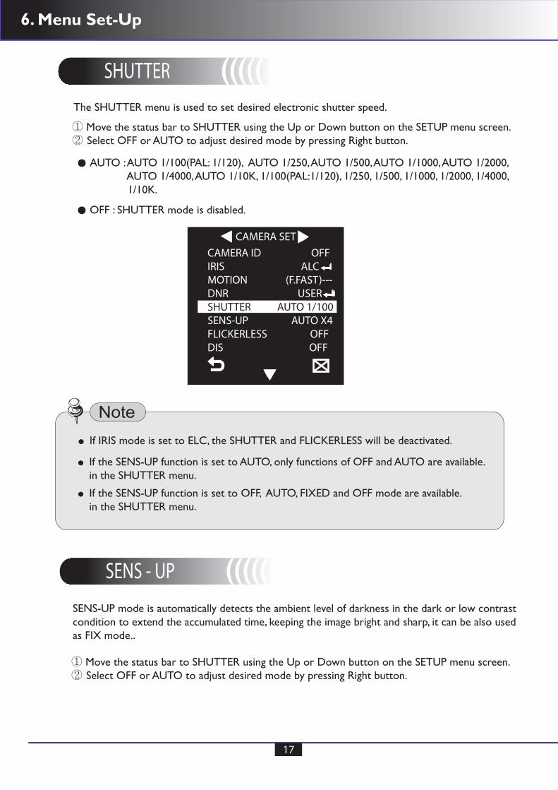
The SHUTTER menu is used to set desired electronic shutter speed.
CAMERA SET
CAMERA ID OFFIRIS ALCMOTION (F.FAST)---DNR USERSHUTTER AUTO 1/100SENS-UP AUTO X4FLICKERLESS OFFDIS OFF
① Move the status bar to SHUTTER using the Up or Down button on the SETUP menu screen.② Select OFF or AUTO to adjust desired mode by pressing Right button.
SENS-UP mode is automatically detects the ambient level of darkness in the dark or low contrastcondition to extend the accumulated time, keeping the image bright and sharp, it can be also usedas FIX mode..
① Move the status bar to SHUTTER using the Up or Down button on the SETUP menu screen.② Select OFF or AUTO to adjust desired mode by pressing Right button.
AUTO : AUTO 1/100(PAL: 1/120), AUTO 1/250, AUTO 1/500, AUTO 1/1000, AUTO 1/2000, AUTO 1/4000, AUTO 1/10K, 1/100(PAL:1/120), 1/250, 1/500, 1/1000, 1/2000, 1/4000, 1/10K.
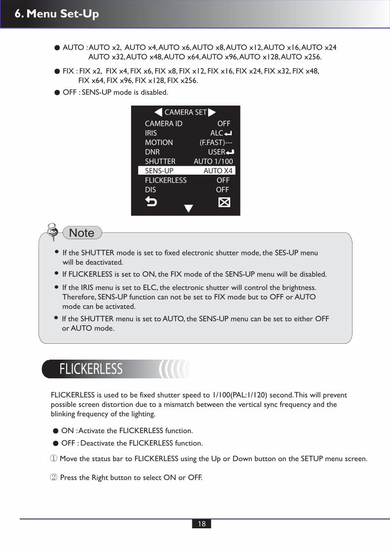
OFF : SHUTTER mode is disabled.
If IRIS mode is set to ELC, the SHUTTER and FLICKERLESS will be deactivated.
If the SENS-UP function is set to AUTO, only functions of OFF and AUTO are available.in the SHUTTER menu.
If the SENS-UP function is set to OFF, AUTO, FIXED and OFF mode are available.in the SHUTTER menu.
6. Menu Set-Up
18
FLICKERLESS (((((
CAMERA SET
CAMERA ID OFFIRIS ALCMOTION (F.FAST)---DNR USERSHUTTER AUTO 1/100SENS-UP AUTO X4FLICKERLESS OFFDIS OFF
FLICKERLESS is used to be fixed shutter speed to 1/100(PAL:1/120) second. This will preventpossible screen distortion due to a mismatch between the vertical sync frequency and the blinking frequency of the lighting.
① Move the status bar to FLICKERLESS using the Up or Down button on the SETUP menu screen.
② Press the Right button to select ON or OFF.
AUTO : AUTO x2, AUTO x4, AUTO x6, AUTO x8, AUTO x12, AUTO x16, AUTO x24 AUTO x32, AUTO x48, AUTO x64, AUTO x96, AUTO x128, AUTO x256.
FIX : FIX x2, FIX x4, FIX x6, FIX x8, FIX x12, FIX x16, FIX x24, FIX x32, FIX x48, FIX x64, FIX x96, FIX x128, FIX x256. OFF : SENS-UP mode is disabled.
OFF : Deactivate the FLICKERLESS function.
ON : Activate the FLICKERLESS function.
If the SHUTTER mode is set to fixed electronic shutter mode, the SES-UP menu will be deactivated.
If FLICKERLESS is set to ON, the FIX mode of the SENS-UP menu will be disabled.
If the SHUTTER menu is set to AUTO, the SENS-UP menu can be set to either OFFor AUTO mode.
If the IRIS menu is set to ELC, the electronic shutter will control the brightness. Therefore, SENS-UP function can not be set to FIX mode but to OFF or AUTOmode can be activated.

6. Menu Set-Up
19
DIS (((((
CAMERA SET
CAMERA ID OFFIRIS ALCMOTION (F.FAST)---DNR USERSHUTTER OFFSENS-UP AUTO X4FLICKERLESS ONDIS OFF
Digital Image Stabilization will be set the anti - shake compensation.
① Move the status bar to DIS using the Up or Down button on the SETUP menu screen.
② Press the Right button to select ON or OFF.
OFF : Deactivate the DIS function.
ON : Activate the DIS function.
CAMERA SET
CAMERA ID OFFIRIS ALCMOTION (F.FAST)---DNR USERSHUTTER OFFSENS-UP AUTO X4FLICKERLESS OFFDIS ON
If the IRIS function is set to ELC, the Flickeless menu will be deactivated. If the SHUTTERmenu is set to AUTO, FIX or EXT mode, the Flickerless mode will be deactivated.
If the SENS-UP mode is set to FIX mode, the FLICKERLESS function will be disabled.
If the AGC mode is set to FIX mode, the FLICKERLESS function will be disabled.
6. Menu Set-Up
20
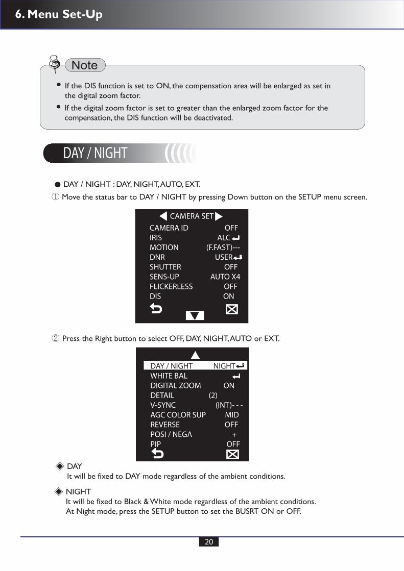
DAY / NIGHT (((((
① Move the status bar to DAY / NIGHT by pressing Down button on the SETUP menu screen.
② Press the Right button to select OFF, DAY, NIGHT, AUTO or EXT.
DAY / NIGHT : DAY, NIGHT, AUTO, EXT.
CAMERA SET
CAMERA ID OFFIRIS ALCMOTION (F.FAST)---DNR USERSHUTTER OFFSENS-UP AUTO X4FLICKERLESS OFFDIS ON
If the DIS function is set to ON, the compensation area will be enlarged as set inthe digital zoom factor.
If the digital zoom factor is set to greater than the enlarged zoom factor for thecompensation, the DIS function will be deactivated.
DAYIt will be fixed to DAY mode regardless of the ambient conditions.
NIGHTIt will be fixed to Black & White mode regardless of the ambient conditions.At Night mode, press the SETUP button to set the BUSRT ON or OFF.
DAY / NIGHT NIGHTWHITE BALDIGITAL ZOOM ONDETAIL (2)V-SYNC (INT)- - -AGC COLOR SUP MIDREVERSE OFFPOSI / NEGA +PIP OFF

6. Menu Set-Up
21
NIGHT
BURST ON
If the BURST is set to ON, the burst signal will output together with the black & whitecomposite video signal.
If the BURST is set to OFF, the burst signal does not output.
The BRIGHTNESS level can be adjusted using Right button from LOW, MID and HIGHwhich is switching the brightness level from the Black & White filter to color.
The DWELL TIME is a requirement time to determine switching the filter.
The MASK is used to prevent a filter switching error or inability of determining theswitch in existence of a high spot light source at night.
AUTOThe camera will automatically switching between DAY and NIGHT mode by the lightingcondition. At AUTO menu, press the SETUP button to adjust desired sub menu values.
AUTO
BURST ONDAY NIGHTBRIGHTNESS MIDDWELL TIME 2SNIGHT DAYBRIGHTNESS MIDDWELL TIME 5SMASK AREA 1 2
DAY NIGHT : NIGHT DAY
6. Menu Set-Up
22
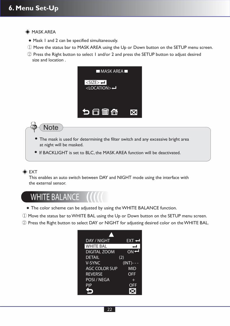
The mask is used for determining the filter switch and any excessive bright area at night will be masked.
If BACKLIGHT is set to BLC, the MASK AREA function will be deactivated.
Mask 1 and 2 can be specified simultaneously.
The color scheme can be adjusted by using the WHITE BALANCE function.
MASK AREA
EXTThis enables an auto switch between DAY and NIGHT mode using the interface withthe external sensor.
① Move the status bar to MASK AREA using the Up or Down button on the SETUP menu screen.
② Press the Right button to select 1 and/or 2 and press the SETUP button to adjust desired size and location .
① Move the status bar to WHITE BAL using the Up or Down button on the SETUP menu screen.
② Press the Right button to select DAY or NIGHT for adjusting desired color on the WHITE BAL.
MASK AREA
<SIZE><LOCATION>
WHITE BALANCE (((((
DAY / NIGHT EXTWHITE BALDIGITAL ZOOM ONDETAIL (2)V-SYNC (INT)- - -AGC COLOR SUP MIDREVERSE OFFPOSI / NEGA +PIP OFF

6. Menu Set-Up
23
Desired R-GAIN and B-GAIN can be controlled in only AWC mode.
DAYIn DAY mode, desired values of RED and BLUE can be adjusted.
ATW1( Auto Tracing White Balance mode 1):The camera can automatically adjust the color temperature in real time according to theambient conditions. The color temperature ranges are from approx. 2,500K to 9,500K.
AWC( Auto White Balance Control):Auto White Balance will perform once in the appropriate item position using SETUP button.
ATW2: The color temperature ranges are from approx. 1,800K to 10,500K.
NIGHTNIGHT mode can be used when it required to set the white balance differently according to theambient luminance..
WHITE BAL
DAY / NIGHT DAYMODE AWC RED ( 00)---I--- BLUE ( 00)---I--- R-GAIN (0248) B-GAIN (0247)
WHITE BAL
DAY / NIGHT NIGHTMODE AWC RED ( 00)---I--- BLUE ( 00)---I--- R-GAIN (0064) B-GAIN (0064)
① Move the status bar to using the Up or Down button on the SETUP menu screen.
② Press the Right button to adjust desiredred color values on the WHITE BAL using Left or Right Button.
6. Menu Set-Up
24
In the NIGHT , the MODE is set to OFF, the white balance will always operate as set in DAY mode; If not to OFF, the camera will switch to as set in DAY/NIGHTmode according to the brightness.
When AGC is set to OFF or FIX, the NIGHT menu is disabled.
When the zoom factor and position are defined, the dizital zoom function will operate.
The DIGITAL ZOOM function enlarges the pixels which can cause deterioration.of the quality.
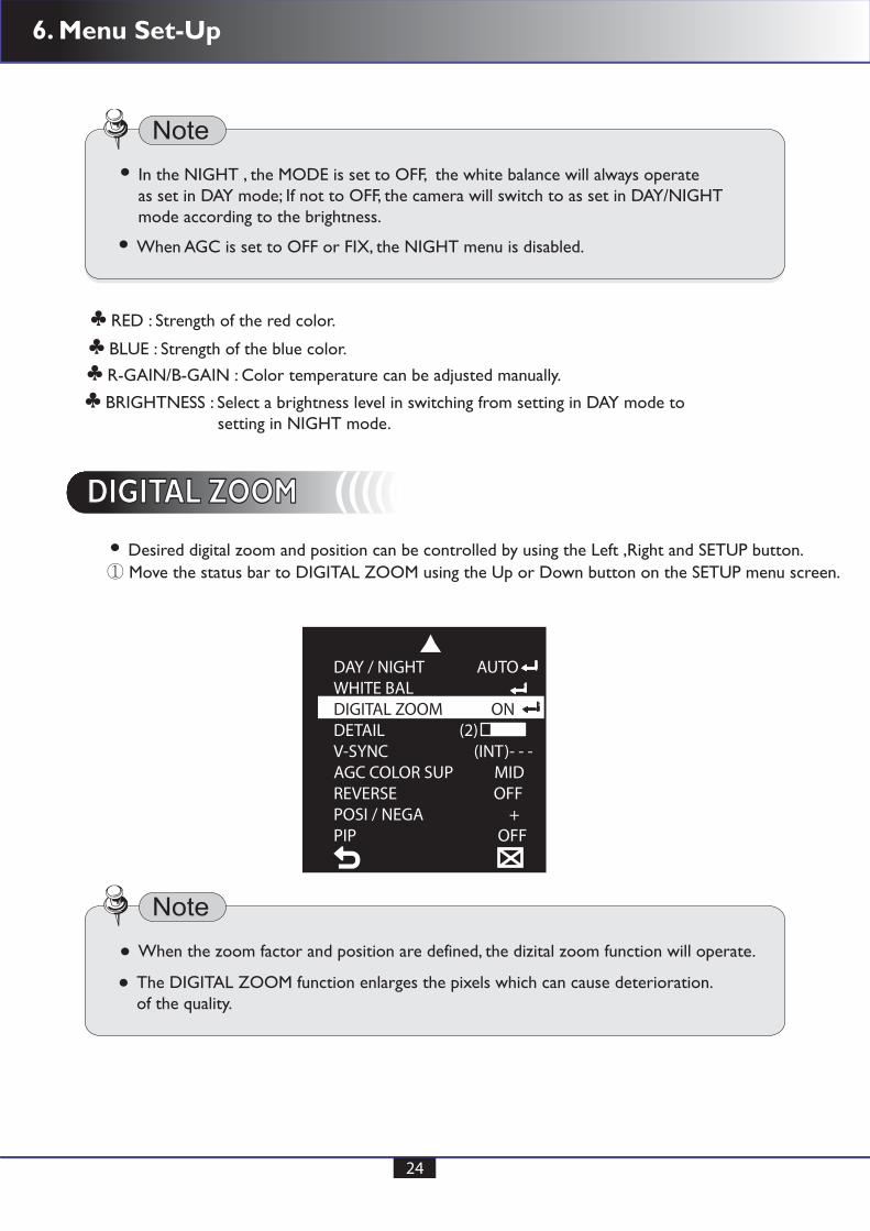
Desired digital zoom and position can be controlled by using the Left ,Right and SETUP button.
RED : Strength of the red color. ♣
BLUE : Strength of the blue color. ♣
R-GAIN/B-GAIN : Color temperature can be adjusted manually. ♣
BRIGHTNESS : Select a brightness level in switching from setting in DAY mode to setting in NIGHT mode.
♣
DIGITAL ZOOM DIGITAL ZOOM (((((
① Move the status bar to DIGITAL ZOOM using the Up or Down button on the SETUP menu screen.
DAY / NIGHT AUTOWHITE BALDIGITAL ZOOM ONDETAIL (2)V-SYNC (INT)- - -AGC COLOR SUP MIDREVERSE OFFPOSI / NEGA +PIP OFF
6. Menu Set-Up
25
If you press the SETUP button in the condition where the image is enlarged as muchas the ratio setting, invisible area of the effective screen can be watched as well usingthe buttons.
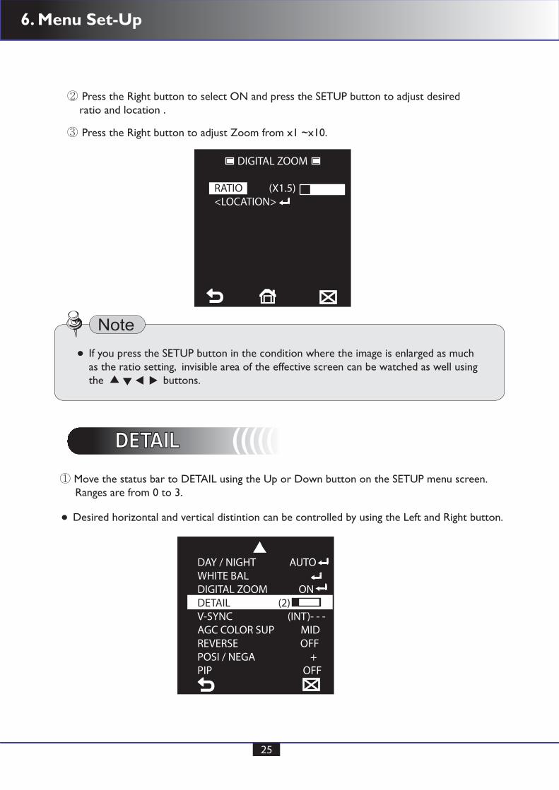
② Press the Right button to select ON and press the SETUP button to adjust desired ratio and location .
③ Press the Right button to adjust Zoom from x1 ~x10.
DIGITAL ZOOM
RATIO (X1.5)<LOCATION>
DETAIL DETAIL (((((
Desired horizontal and vertical distintion can be controlled by using the Left and Right button.
① Move the status bar to DETAIL using the Up or Down button on the SETUP menu screen. Ranges are from 0 to 3.
DAY / NIGHT AUTOWHITE BALDIGITAL ZOOM ONDETAIL (2)V-SYNC (INT)- - -AGC COLOR SUP MIDREVERSE OFFPOSI / NEGA +PIP OFF

6. Menu Set-Up
26
REVERSE REVERSE (((((
POSI/NEGA POSI/NEGA (((((
① Move the status bar to REVERSE using the Up or Down button and press Right button to adjust desired picture position.
① Move the status bar to POSI/NEGA using the Up or Down button and press Right button to adjust desired mode.
DAY / NIGHT AUTOWHITE BALDIGITAL ZOOM ONDETAIL (2)V-SYNC (INT)- - -AGC COLOR SUP MIDREVERSE H/VPOSI / NEGA +PIP OFF
DAY / NIGHT AUTOWHITE BALDIGITAL ZOOM ONDETAIL (2)V-SYNC (INT)- - -AGC COLOR SUP MIDREVERSE H/VPOSI / NEGA +PIP OFF
H : Horizontal mirror video signal. ♣
V : Vertical mirror video signal. ♣
H/V : Mirror video signal. ♣
OFF : Deactivated. ♣
6. Menu Set-Up
27
REVERSE REVERSE (((((
POSI/NEGA POSI/NEGA (((((
① Move the status bar to REVERSE using the Up or Down button and press Right button to adjust desired picture position.
① Move the status bar to POSI/NEGA using the Up or Down button and press Right button to adjust desired mode.
DAY / NIGHT AUTOWHITE BALDIGITAL ZOOM ONDETAIL (2)V-SYNC (INT)- - -AGC COLOR SUP MIDREVERSE H/VPOSI / NEGA +PIP OFF
DAY / NIGHT AUTOWHITE BALDIGITAL ZOOM ONDETAIL (2)V-SYNC (INT)- - -AGC COLOR SUP MIDREVERSE H/VPOSI / NEGA +PIP OFF
H : Horizontal mirror video signal. ♣
V : Vertical mirror video signal. ♣
H/V : Mirror video signal. ♣
OFF : Deactivated. ♣
6. Menu Set-Up
28
PIP PIP (((((① Move the status bar to PIP using the Up or Down button and press Right button to use the PIP ON/OFF mode.
DAY / NIGHT AUTOWHITE BALDIGITAL ZOOM ONDETAIL (2)V-SYNC (INT)- - -AGC COLOR SUP MIDREVERSE H/VPOSI / NEGA +PIP OFF
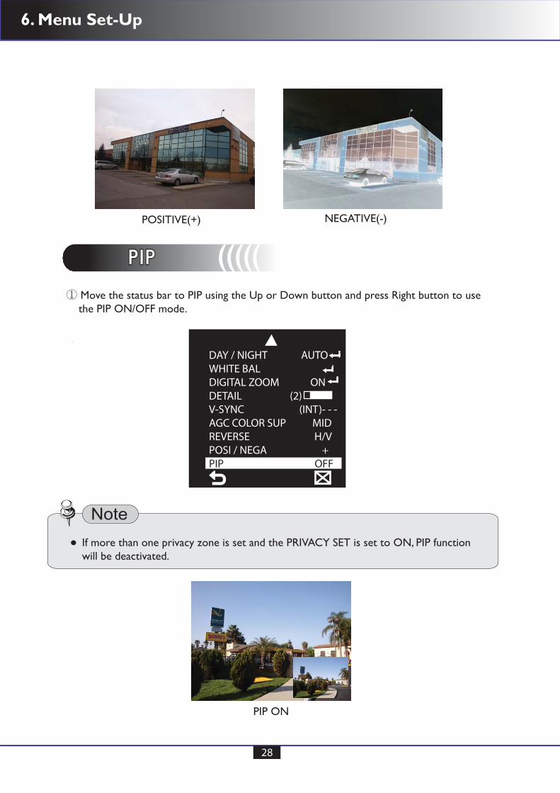
POSITIVE(+)
PIP ON
NEGATIVE(-)
If more than one privacy zone is set and the PRIVACY SET is set to ON, PIP functionwill be deactivated.
6. Menu Set-Up
29
MOTION MOTION (((((
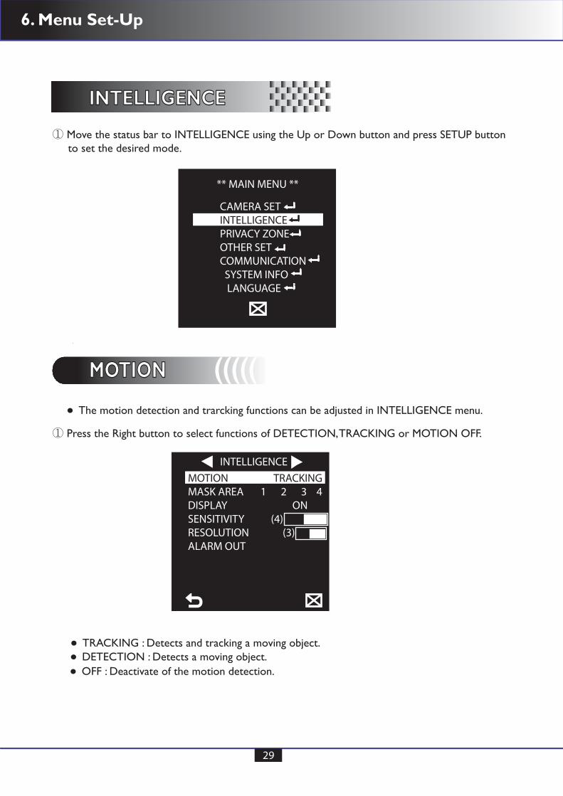
① Move the status bar to INTELLIGENCE using the Up or Down button and press SETUP button to set the desired mode.
① Press the Right button to select functions of DETECTION, TRACKING or MOTION OFF.
TRACKING : Detects and tracking a moving object.DETECTION : Detects a moving object.OFF : Deactivate of the motion detection.
The motion detection and trarcking functions can be adjusted in INTELLIGENCE menu.
** MAIN MENU **
CAMERA SETINTELLIGENCEPRIVACY ZONEOTHER SETCOMMUNICATION SYSTEM INFO LANGUAGE
INTELLIGENCEINTELLIGENCE
INTELLIGENCEMOTION TRACKINGMASK AREA 1 2 3 4DISPLAY ONSENSITIVITY (4)RESOLUTION (3)ALARM OUT
6. Menu Set-Up
30
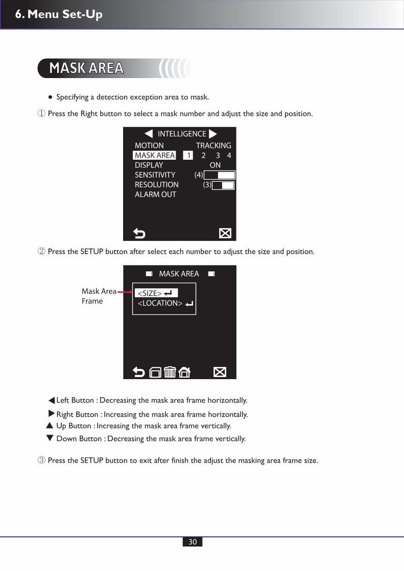
MASK AREA MASK AREA (((((
① Press the Right button to select a mask number and adjust the size and position.
② Press the SETUP button after select each number to adjust the size and position.
③ Press the SETUP button to exit after finish the adjust the masking area frame size.
Specifying a detection exception area to mask.
Left Button : Decreasing the mask area frame horizontally.
Right Button : Increasing the mask area frame horizontally.Up Button : Increasing the mask area frame vertically.
Down Button : Decreasing the mask area frame vertically.
INTELLIGENCEMOTION TRACKINGMASK AREA 1 2 3 4DISPLAY ONSENSITIVITY (4)RESOLUTION (3)ALARM OUT
MASK AREA
Mask AreaFrame
<SIZE><LOCATION>

6. Menu Set-Up
31
MASK AREA MASK AREA (((((
① Move the status bar to LOCATION to set the position of masking ares frame.
② Press the SETUP button to select position of the masking area frame.
③ Press the SETUP button to exit after finish the adjust the masking area position.
Left Button : Moving the mask area frame to LEFT side.
Right Button : Moving the mask area frame to RIGHT side.Up Button : Moving the mask area frame to UPPER side.
Down Button : Moving the mask area frame to Lower side.
MASK AREA
Mask AreaFrame
<SIZE><LOCATION>
MASK AREA
Mask AreaFrame
<SIZE><LOCATION>
6. Menu Set-Up
32
DISPLAY DISPLAY (((((
SENSITIVITY SENSITIVITY (((((
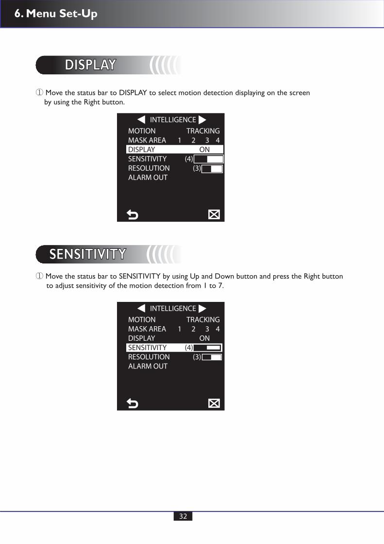
① Move the status bar to DISPLAY to select motion detection displaying on the screen by using the Right button.
① Move the status bar to SENSITIVITY by using Up and Down button and press the Right button to adjust sensitivity of the motion detection from 1 to 7.
INTELLIGENCEMOTION TRACKINGMASK AREA 1 2 3 4DISPLAY ONSENSITIVITY (4)RESOLUTION (3)ALARM OUT
INTELLIGENCEMOTION TRACKINGMASK AREA 1 2 3 4DISPLAY ONSENSITIVITY (4)RESOLUTION (3)ALARM OUT
6. Menu Set-Up
33
RESOLUTION RESOLUTION (((((
ALARM OUT ALARM OUT (((((
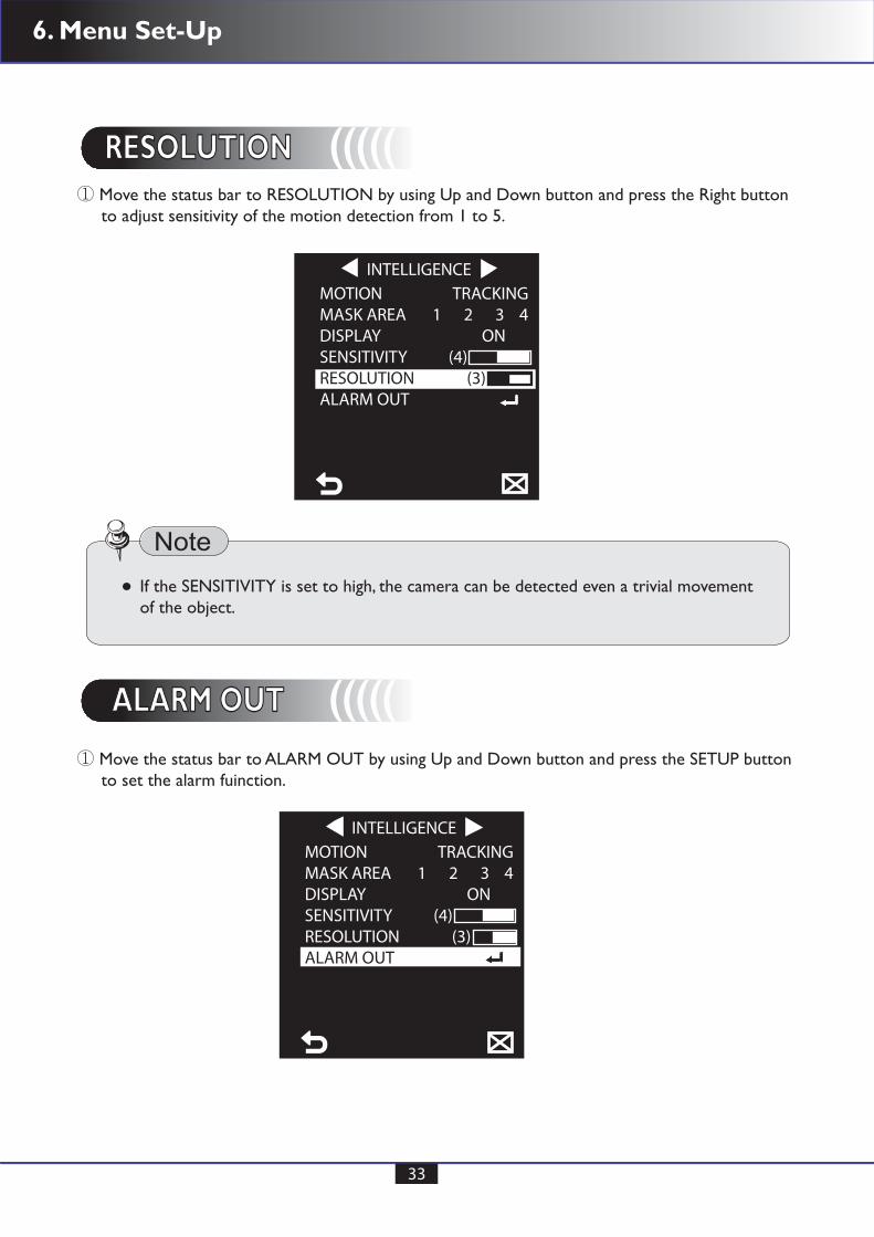
① Move the status bar to RESOLUTION by using Up and Down button and press the Right button to adjust sensitivity of the motion detection from 1 to 5.
① Move the status bar to ALARM OUT by using Up and Down button and press the SETUP button to set the alarm fuinction.
INTELLIGENCEMOTION TRACKINGMASK AREA 1 2 3 4DISPLAY ONSENSITIVITY (4)RESOLUTION (3)ALARM OUT
If the SENSITIVITY is set to high, the camera can be detected even a trivial movementof the object.
INTELLIGENCEMOTION TRACKINGMASK AREA 1 2 3 4DISPLAY ONSENSITIVITY (4)RESOLUTION (3)ALARM OUT

6. Menu Set-Up
34
② Set the alarm ON by using the Right button and the camera will sound an alert when detect the motion in ALARM mode.
Originally alarm out put mode is not available from the factory default, please discusswith your distributor where you purchased the camera and Alarm out put functionshould be OPTIONAL .
ALARM OUT
Caution
MOTION ON
PRIVACY ZONEPRIVACY ZONEThe PRIVACY function will protect the privacy by screening the privacy area duringmonitoring. The 8 privacy zones are specified.
① Move the status bar to PRIVACY ZONE using the Up or Down button and press SETUP button to set the desired privacy zone number.
PRIVACY ZONE
1 2 3 45 6 7 8
PRIVACY SET ONSTYLE MOSAIC1

6. Menu Set-Up
35
② Move the status bar to PRIVACY to select ON and OFF by using the Right button.
③ Move the status bar to STYLE to select MOSAIC style.
In case of more than one PRIVACY ZONE is specified and the PRIVACY SET is to setto ON, the PIP function will be deactivated.
In case of the 12th PRIVACY ZONE is specified, the LINE function of FENCE will be deactivated.
PRIVACY ZONE
1 2 3 45 6 7 8
PRIVACY SET ONSTYLE MOSAIC1
PRIVACY ZONE
1 2 3 45 6 7 8
PRIVACY SET ONSTYLE COLORY-LEVEL (128)RED (128)BLUE (128)
MOSAIC STYLE: MOSAIC1, MOSAIC2, MOSAIC3, MOSAIC4 and adjustble COLOR.
Y-LEVEL can be adjusted from 0 to 200
RED: Color can be adjusted from 0 to 210
BLUE: Color can be adjusted from 0 to 210
♣
6. Menu Set-Up
36
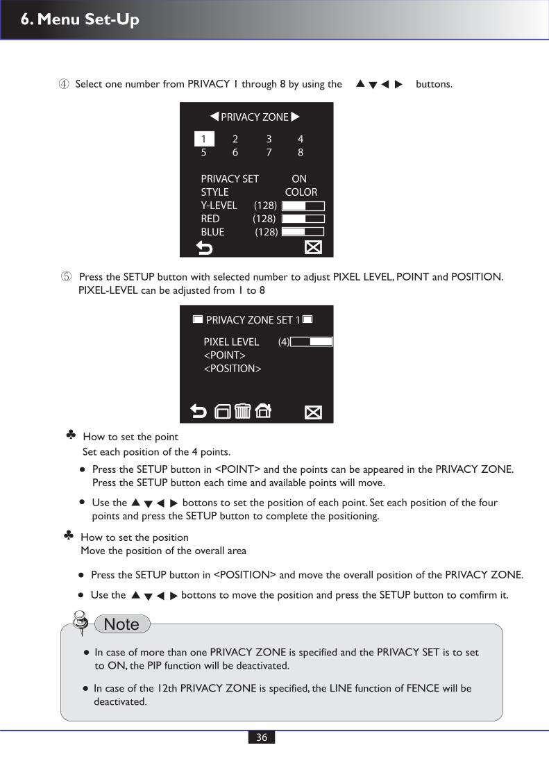
④ Select one number from PRIVACY 1 through 8 by using the buttons.
⑤ Press the SETUP button with selected number to adjust PIXEL LEVEL, POINT and POSITION.
PRIVACY ZONE SET 1
PIXEL LEVEL (4)<POINT><POSITION>
PRIVACY ZONE
Press the SETUP button in <POINT> and the points can be appeared in the PRIVACY ZONE.Press the SETUP button each time and available points will move.
Press the SETUP button in <POSITION> and move the overall position of the PRIVACY ZONE.
Set each position of the 4 points.
PIXEL-LEVEL can be adjusted from 1 to 8
How to set the point
Use the bottons to set the position of each point. Set each position of the four points and press the SETUP button to complete the positioning.
Use the bottons to move the position and press the SETUP button to comfirm it.
♣
How to set the positionMove the position of the overall area
♣
1 2 3 45 6 7 8
PRIVACY SET ONSTYLE COLORY-LEVEL (128)RED (128)BLUE (128)
In case of more than one PRIVACY ZONE is specified and the PRIVACY SET is to setto ON, the PIP function will be deactivated.
In case of the 12th PRIVACY ZONE is specified, the LINE function of FENCE will be deactivated.
6. Menu Set-Up
37
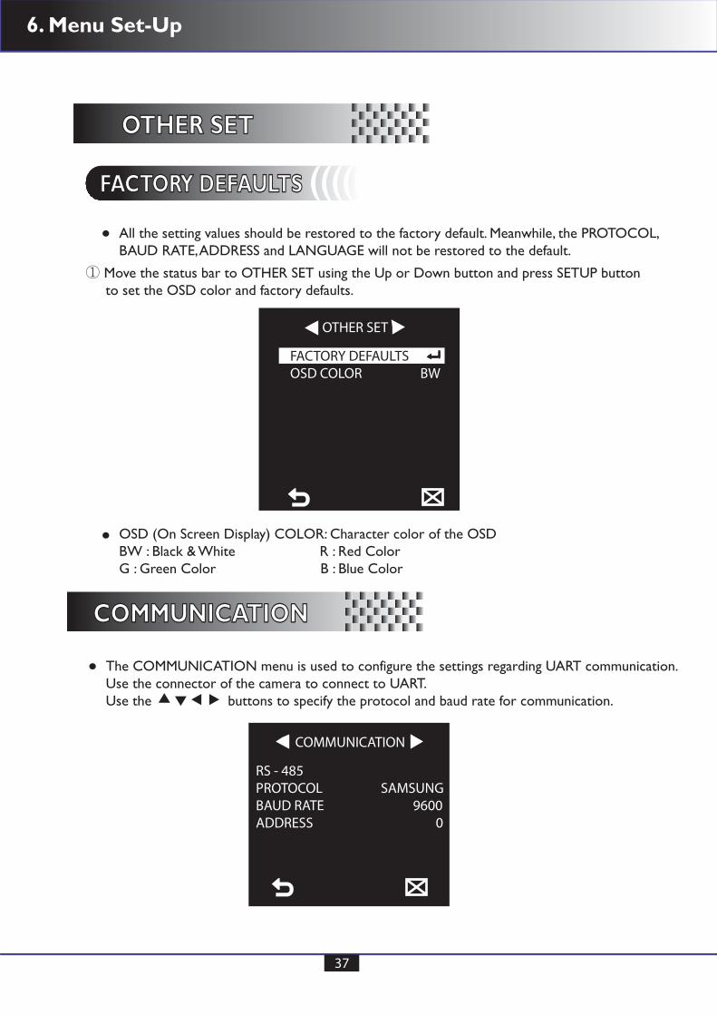
All the setting values should be restored to the factory default. Meanwhile, the PROTOCOL,BAUD RATE, ADDRESS and LANGUAGE will not be restored to the default.
The COMMUNICATION menu is used to configure the settings regarding UART communication.Use the connector of the camera to connect to UART.Use the buttons to specify the protocol and baud rate for communication.
OSD (On Screen Display) COLOR: Character color of the OSDBW : Black & White R : Red ColorG : Green Color B : Blue Color
OTHER SETOTHER SET
COMMUNICATIONCOMMUNICATION
① Move the status bar to OTHER SET using the Up or Down button and press SETUP button to set the OSD color and factory defaults.
OTHER SET
FACTORY DEFAULTSOSD COLOR BW
FACTORY DEFAULTSFACTORY DEFAULTS (((((
COMMUNICATION
RS - 485PROTOCOL SAMSUNGBAUD RATE 9600ADDRESS 0
6. Menu Set-Up
38
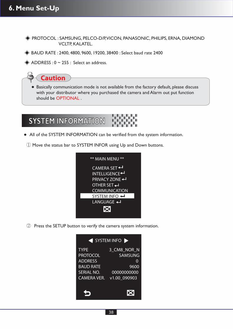
All of the SYSTEM INFORMATION can be verified from the system information.
SYSTEM INFORMATIONSYSTEM INFORMATION
PROTOCOL : SAMSUNG, PELCO-D/P, VICON, PANASONIC, PHILIPS, ERNA, DIAMOND VCLTP, KALATEL.
BAUD RATE : 2400, 4800, 9600, 19200, 38400 : Select baud rate 2400
ADDRESS : 0 ~ 255 : Select an address.
SYSTEM INFO
TYPE 3_CM8_NOR_NPROTOCOL SAMSUNGADDRESS 0BAUD RATE 9600SERIAL NO. 00000000000CAMERA VER. v1.00_090903
Basically communication mode is not available from the factory default, please discusswith your distributor where you purchased the camera and Alarm out put functionshould be OPTIONAL .
Caution
** MAIN MENU **
CAMERA SETINTELLIGENCEPRIVACY ZONEOTHER SETCOMMUNICATIONSYSTEM INFOLANGUAGE
① Move the status bar to SYSTEM INFOR using Up and Down buttons.
② Press the SETUP button to verify the camera system information.

6. Menu Set-Up
39
The camera supports 5 different languages for user’s convenince. Desireable LanguageCan be selected.
LANGUAGELANGUAGE
① Move the status bar to LANGUAGE using Up and Down buttons.
② Press the SETUP buttons and select desired language by using Up and Down button.
** MAIN MENU **
CAMERA SETINTELLIGENCEPRIVACY ZONEOTHER SETCOMMUNICATIONSYSTEM INFOLANGUAGE
LANGUAGE
*ENGLISH FRANCES ESPANOLJAPANESEPORTUGUES

6. Menu Set-Up
40
After complete all reqired function settings, move the status bar to save the data.
EXITEXIT
① Move the status bar to using Down buttons.
② Press the SETUP buttons and select SAVE by using Left and Right button for a second and all the datas will save and exit automatically.
** MAIN MENU **
CAMERA SETINTELLIGENCEPRIVACY ZONEOTHER SETCOMMUNICATIONSYSTEM INFOLANGUAGE
EXIT
SAVE QUIT

7. Factory Defaults
41
Initial factory defaults configuration table
FUNCTIONS
CAMERA ID
IRIS
AGC
MOTION
DNR
DIS
DAY & NIGHT
DIGITAL ZOOM
DETAIL
REVERSE
POSI / NEGA
PIP
V - SYNC
AGC COLOR SUP
[2]
SHUTTER
SENS-UP
FLICKERLESS
AUTO x4
AUTO
OFF
OFF
OFF
OFF
OFF
INT
+
OFF
MID
MID
(F.FAST)
ALC
VERY HIGH
STATUS
OFF
FACTORY DEFAULTSFACTORY DEFAULTS
8. Trouble Shoot
42
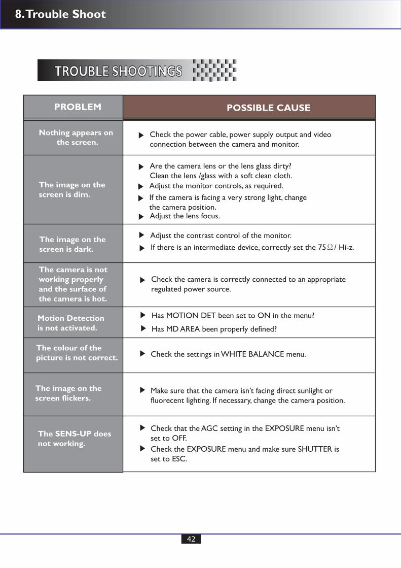
TROUBLE SHOOTINGSTROUBLE SHOOTINGS
PROBLEM
Nothing appears on the screen.
The image on the screen is dim.
The image on the screen is dark.
Motion Detectionis not activated.
The colour of thepicture is not correct.
The image on the screen flickers.
The SENS-UP doesnot working.
The camera is not working properlyand the surface ofthe camera is hot.
POSSIBLE CAUSE
Check the power cable, power supply output and videoconnection between the camera and monitor.
Are the camera lens or the lens glass dirty?Clean the lens /glass with a soft clean cloth.
Adjust the monitor controls, as required.
Adjust the lens focus.
Adjust the contrast control of the monitor.
If the camera is facing a very strong light, changethe camera position.
If there is an intermediate device, correctly set the 75Ω/ Hi-z.
Has MOTION DET been set to ON in the menu?
Has MD AREA been properly defined?
Check the settings in WHITE BALANCE menu.
Check that the AGC setting in the EXPOSURE menu isn’tset to OFF.
Check the EXPOSURE menu and make sure SHUTTER is set to ESC.
Make sure that the camera isn’t facing direct sunlight orfluorecent lighting. If necessary, change the camera position.
Check the camera is correctly connected to an appropriateregulated power source.

Made in Korea


![Treatment Of Congenital Clubfoot Using The Ponseti · PDF fileIris Lohan Treatment Of Congenital Clubfoot Using The Ponseti Method Workshop Manual [2nd Edition]](https://static.documents.pub/doc/80x56/5a9d8bd67f8b9a21688c2ac8/treatment-of-congenital-clubfoot-using-the-ponseti-lohan-treatment-of-congenital.jpg)


