230
HP xw9300 Workstation Service and Technical Reference Guide First Edition: 02/2005 Second Edition: 04/2005
| Date post: | 19-Jan-2016 |
| Category: |
Documents |
| Upload: | muhammad-usman-amir |
| View: | 66 times |
| Download: | 4 times |

HP xw9300 WorkstationService and Technical Reference Guide
First Edition: 02/2005Second Edition: 04/2005

Copyright Information
© 2005 Copyright Hewlett-Packard Development Company, L.P.
First Edition: February 2005Second Edition: April 2005
Warranty
Hewlett-Packard Company shall not be liable for technical or editorial errors or omissions contained herein or for incidental or consequential damages in connection with the furnishing, performance, or use of this material. The information in this document is provided “as is” without warranty of any kind, including, but not limited to, the implied warranties of merchantability and fitness for a particular purpose, and is subject to change without notice. The warranties for HP products are set forth in the express limited warranty statements accompanying such products.
Nothing herein should be construed as constituting and additional warranty.
This document contains proprietary information that is protected by copyright. No part of this document may be photocopied, reproduced, or translated to another language without the prior written consent of Hewlett-Packard Company.
Trademark Credits
The HP Invent logo is a trademark of Hewlett-Packard Company in the U.S. and other countries.
Microsoft and Windows are trademarks of Microsoft Corporation in the U.S. and other countries.
Red Hat is a registered trademark of Red Hat, Inc.
Linux is a registered trademark of Linus Torvalds.
Acrobat and Acrobat Reader are trademarks of Adobe Systems Incorporated.
Energy Star is U.S. registered mark of the United States Environmental Protection Agency.

Con
tent
s
Contents
PrefaceImportant Safety Warnings . . . . . . . . . . . . . . . . . . . . . . . . . . . . . . . . . . . . . . . . . . . . . . . . . . . . . . . . 10Updating BIOS, Drivers, and Software . . . . . . . . . . . . . . . . . . . . . . . . . . . . . . . . . . . . . . . . . . . . . . . . 13Finding Information. . . . . . . . . . . . . . . . . . . . . . . . . . . . . . . . . . . . . . . . . . . . . . . . . . . . . . . . . . . . . . 14
E-Support . . . . . . . . . . . . . . . . . . . . . . . . . . . . . . . . . . . . . . . . . . . . . . . . . . . . . . . . . . . . . . . . . . 14Additional Documentation. . . . . . . . . . . . . . . . . . . . . . . . . . . . . . . . . . . . . . . . . . . . . . . . . . . . . . . 14Helpful Links . . . . . . . . . . . . . . . . . . . . . . . . . . . . . . . . . . . . . . . . . . . . . . . . . . . . . . . . . . . . . . . . 14Using the Documentation Library and Diagnostics CD . . . . . . . . . . . . . . . . . . . . . . . . . . . . . . . . . . . 15
Windows-Based Workstations . . . . . . . . . . . . . . . . . . . . . . . . . . . . . . . . . . . . . . . . . . . . . . . . . 15Linux-Based Workstations. . . . . . . . . . . . . . . . . . . . . . . . . . . . . . . . . . . . . . . . . . . . . . . . . . . . . 15
Locating Regulatory Information. . . . . . . . . . . . . . . . . . . . . . . . . . . . . . . . . . . . . . . . . . . . . . . . . . . 15Parts and Accessories. . . . . . . . . . . . . . . . . . . . . . . . . . . . . . . . . . . . . . . . . . . . . . . . . . . . . . . . . . 15Subscriber’s Choice . . . . . . . . . . . . . . . . . . . . . . . . . . . . . . . . . . . . . . . . . . . . . . . . . . . . . . . . . . . 15
1 Product OverviewProduct Features . . . . . . . . . . . . . . . . . . . . . . . . . . . . . . . . . . . . . . . . . . . . . . . . . . . . . . . . . . . . . . . . 18
Exploded View . . . . . . . . . . . . . . . . . . . . . . . . . . . . . . . . . . . . . . . . . . . . . . . . . . . . . . . . . . . . . . 18Front Panel Components . . . . . . . . . . . . . . . . . . . . . . . . . . . . . . . . . . . . . . . . . . . . . . . . . . . . . . . . 19Rear Panel Components . . . . . . . . . . . . . . . . . . . . . . . . . . . . . . . . . . . . . . . . . . . . . . . . . . . . . . . . 20Serial Number and COA Label Location. . . . . . . . . . . . . . . . . . . . . . . . . . . . . . . . . . . . . . . . . . . . . 21
Product Specifications . . . . . . . . . . . . . . . . . . . . . . . . . . . . . . . . . . . . . . . . . . . . . . . . . . . . . . . . . . . . 22Power Supply and Cooling . . . . . . . . . . . . . . . . . . . . . . . . . . . . . . . . . . . . . . . . . . . . . . . . . . . . . . . . 23
Power Output and Cooling . . . . . . . . . . . . . . . . . . . . . . . . . . . . . . . . . . . . . . . . . . . . . . . . . . . . . . 24Power Supply Specifications . . . . . . . . . . . . . . . . . . . . . . . . . . . . . . . . . . . . . . . . . . . . . . . . . . . . . 26Power Consumption and Cooling. . . . . . . . . . . . . . . . . . . . . . . . . . . . . . . . . . . . . . . . . . . . . . . . . . 27System Fans and Airflow. . . . . . . . . . . . . . . . . . . . . . . . . . . . . . . . . . . . . . . . . . . . . . . . . . . . . . . . 28Resetting the Power Supply . . . . . . . . . . . . . . . . . . . . . . . . . . . . . . . . . . . . . . . . . . . . . . . . . . . . . . 29
Environmental Specification . . . . . . . . . . . . . . . . . . . . . . . . . . . . . . . . . . . . . . . . . . . . . . . . . . . . . . . 30PCI and PCI Express Slot Power Specifications . . . . . . . . . . . . . . . . . . . . . . . . . . . . . . . . . . . . . . . . . . . 31ENERGY STAR . . . . . . . . . . . . . . . . . . . . . . . . . . . . . . . . . . . . . . . . . . . . . . . . . . . . . . . . . . . . . . . . . 32
ENERGY STAR Compliance . . . . . . . . . . . . . . . . . . . . . . . . . . . . . . . . . . . . . . . . . . . . . . . . . . . . . 32
2 Installing or Restoring the Operating SystemInstalling the Operating System and Software . . . . . . . . . . . . . . . . . . . . . . . . . . . . . . . . . . . . . . . . . . . 34
Microsoft Windows XP Professional . . . . . . . . . . . . . . . . . . . . . . . . . . . . . . . . . . . . . . . . . . . . . . . . 34Installing or Upgrading Device Drivers. . . . . . . . . . . . . . . . . . . . . . . . . . . . . . . . . . . . . . . . . . . . 34Creating a Restore Diskette . . . . . . . . . . . . . . . . . . . . . . . . . . . . . . . . . . . . . . . . . . . . . . . . . . . 34
Linux-Preinstalled Workstations . . . . . . . . . . . . . . . . . . . . . . . . . . . . . . . . . . . . . . . . . . . . . . . . . . . 35Starting the Linux Operating System . . . . . . . . . . . . . . . . . . . . . . . . . . . . . . . . . . . . . . . . . . . . . 35Restoring the Linux Operating System . . . . . . . . . . . . . . . . . . . . . . . . . . . . . . . . . . . . . . . . . . . . 35Upgrading Device Drivers . . . . . . . . . . . . . . . . . . . . . . . . . . . . . . . . . . . . . . . . . . . . . . . . . . . . 36
Linux-Enabled Workstations. . . . . . . . . . . . . . . . . . . . . . . . . . . . . . . . . . . . . . . . . . . . . . . . . . . . . . 37Verifying Hardware Compatibility. . . . . . . . . . . . . . . . . . . . . . . . . . . . . . . . . . . . . . . . . . . . . . . 37Installing the Linux Operating System. . . . . . . . . . . . . . . . . . . . . . . . . . . . . . . . . . . . . . . . . . . . . 37Upgrading Device Drivers . . . . . . . . . . . . . . . . . . . . . . . . . . . . . . . . . . . . . . . . . . . . . . . . . . . . 37
HP Software . . . . . . . . . . . . . . . . . . . . . . . . . . . . . . . . . . . . . . . . . . . . . . . . . . . . . . . . . . . . . . . . 38Restoring the Operating System . . . . . . . . . . . . . . . . . . . . . . . . . . . . . . . . . . . . . . . . . . . . . . . . . . . . . 39Protecting the Software . . . . . . . . . . . . . . . . . . . . . . . . . . . . . . . . . . . . . . . . . . . . . . . . . . . . . . . . . . . 40Ordering Backup Software . . . . . . . . . . . . . . . . . . . . . . . . . . . . . . . . . . . . . . . . . . . . . . . . . . . . . . . . 41
Contents 3

3 System ManagementComputer Setup (F10) . . . . . . . . . . . . . . . . . . . . . . . . . . . . . . . . . . . . . . . . . . . . . . . . . . . . . . . . . . . . 44
BIOS ROM . . . . . . . . . . . . . . . . . . . . . . . . . . . . . . . . . . . . . . . . . . . . . . . . . . . . . . . . . . . . . . . . . 45Using Computer Setup (F10) . . . . . . . . . . . . . . . . . . . . . . . . . . . . . . . . . . . . . . . . . . . . . . . . . . . . . 46Computer Setup Menu . . . . . . . . . . . . . . . . . . . . . . . . . . . . . . . . . . . . . . . . . . . . . . . . . . . . . . . . . 47
Desktop Management . . . . . . . . . . . . . . . . . . . . . . . . . . . . . . . . . . . . . . . . . . . . . . . . . . . . . . . . . . . . 54Initial Configuration and Deployment . . . . . . . . . . . . . . . . . . . . . . . . . . . . . . . . . . . . . . . . . . . . . . . 55Remote System Installation . . . . . . . . . . . . . . . . . . . . . . . . . . . . . . . . . . . . . . . . . . . . . . . . . . . . . . 56Software Updating and Management . . . . . . . . . . . . . . . . . . . . . . . . . . . . . . . . . . . . . . . . . . . . . . 57
HP Client Manager Software . . . . . . . . . . . . . . . . . . . . . . . . . . . . . . . . . . . . . . . . . . . . . . . . . . 57Altiris Client Management Solutions . . . . . . . . . . . . . . . . . . . . . . . . . . . . . . . . . . . . . . . . . . . . . 57System Software Manager . . . . . . . . . . . . . . . . . . . . . . . . . . . . . . . . . . . . . . . . . . . . . . . . . . . . 58Proactive Change Notification . . . . . . . . . . . . . . . . . . . . . . . . . . . . . . . . . . . . . . . . . . . . . . . . . 58Subscriber’s Choice . . . . . . . . . . . . . . . . . . . . . . . . . . . . . . . . . . . . . . . . . . . . . . . . . . . . . . . . 58
ROM Flash . . . . . . . . . . . . . . . . . . . . . . . . . . . . . . . . . . . . . . . . . . . . . . . . . . . . . . . . . . . . . . . . . 59Remote ROM Flash . . . . . . . . . . . . . . . . . . . . . . . . . . . . . . . . . . . . . . . . . . . . . . . . . . . . . . . . . 59HPQFlash . . . . . . . . . . . . . . . . . . . . . . . . . . . . . . . . . . . . . . . . . . . . . . . . . . . . . . . . . . . . . . . 59FailSafe Boot Block ROM. . . . . . . . . . . . . . . . . . . . . . . . . . . . . . . . . . . . . . . . . . . . . . . . . . . . . 59Replicating the Setup. . . . . . . . . . . . . . . . . . . . . . . . . . . . . . . . . . . . . . . . . . . . . . . . . . . . . . . . 61Dual-State Power Button. . . . . . . . . . . . . . . . . . . . . . . . . . . . . . . . . . . . . . . . . . . . . . . . . . . . . . 62World Wide Web Site . . . . . . . . . . . . . . . . . . . . . . . . . . . . . . . . . . . . . . . . . . . . . . . . . . . . . . 63Building Blocks and Partners . . . . . . . . . . . . . . . . . . . . . . . . . . . . . . . . . . . . . . . . . . . . . . . . . . 63
Asset Tracking and Security . . . . . . . . . . . . . . . . . . . . . . . . . . . . . . . . . . . . . . . . . . . . . . . . . . . . . 64Password Security. . . . . . . . . . . . . . . . . . . . . . . . . . . . . . . . . . . . . . . . . . . . . . . . . . . . . . . . . . 65Deleting a Power-On or Setup Password . . . . . . . . . . . . . . . . . . . . . . . . . . . . . . . . . . . . . . . . . . 68Hood Sensor (Smart Cover Sensor) . . . . . . . . . . . . . . . . . . . . . . . . . . . . . . . . . . . . . . . . . . . . . . 69Cable Lock Provision (Optional) . . . . . . . . . . . . . . . . . . . . . . . . . . . . . . . . . . . . . . . . . . . . . . . . 70Security Lock (Optional). . . . . . . . . . . . . . . . . . . . . . . . . . . . . . . . . . . . . . . . . . . . . . . . . . . . . . 70Universal Chassis Clamp Lock (Optional) . . . . . . . . . . . . . . . . . . . . . . . . . . . . . . . . . . . . . . . . . . 70Hood Sensor (Smart Cover Sensor) . . . . . . . . . . . . . . . . . . . . . . . . . . . . . . . . . . . . . . . . . . . . . . 70Access Panel Key Lock. . . . . . . . . . . . . . . . . . . . . . . . . . . . . . . . . . . . . . . . . . . . . . . . . . . . . . . 70
Fault Notification and Recovery. . . . . . . . . . . . . . . . . . . . . . . . . . . . . . . . . . . . . . . . . . . . . . . . . . . 71Drive Protection System . . . . . . . . . . . . . . . . . . . . . . . . . . . . . . . . . . . . . . . . . . . . . . . . . . . . . . 71ECC Fault Prediction and Prefailure Warranty . . . . . . . . . . . . . . . . . . . . . . . . . . . . . . . . . . . . . . 71Surge-Tolerant Power Supply . . . . . . . . . . . . . . . . . . . . . . . . . . . . . . . . . . . . . . . . . . . . . . . . . . 71Thermal Sensor. . . . . . . . . . . . . . . . . . . . . . . . . . . . . . . . . . . . . . . . . . . . . . . . . . . . . . . . . . . . 71
4 Removal and Replacement ProceduresService Considerations . . . . . . . . . . . . . . . . . . . . . . . . . . . . . . . . . . . . . . . . . . . . . . . . . . . . . . . . . . . 74
Cautions, Warnings, and Safety Precautions. . . . . . . . . . . . . . . . . . . . . . . . . . . . . . . . . . . . . . . . . . 74Electrostatic Discharge Information. . . . . . . . . . . . . . . . . . . . . . . . . . . . . . . . . . . . . . . . . . . . . . . . . 75
Generating Static . . . . . . . . . . . . . . . . . . . . . . . . . . . . . . . . . . . . . . . . . . . . . . . . . . . . . . . . . . 75Preventing Electrostatic Damage to Equipment . . . . . . . . . . . . . . . . . . . . . . . . . . . . . . . . . . . . . . 75Personal Grounding Methods and Equipment . . . . . . . . . . . . . . . . . . . . . . . . . . . . . . . . . . . . . . . 76Grounding the Work Area. . . . . . . . . . . . . . . . . . . . . . . . . . . . . . . . . . . . . . . . . . . . . . . . . . . . 76Recommended Materials and Equipment . . . . . . . . . . . . . . . . . . . . . . . . . . . . . . . . . . . . . . . . . . 76
Tools and Software Requirements . . . . . . . . . . . . . . . . . . . . . . . . . . . . . . . . . . . . . . . . . . . . . . . . . 77Screws . . . . . . . . . . . . . . . . . . . . . . . . . . . . . . . . . . . . . . . . . . . . . . . . . . . . . . . . . . . . . . . . . 77
Special Handling of Components . . . . . . . . . . . . . . . . . . . . . . . . . . . . . . . . . . . . . . . . . . . . . . . . . 77Cables and Connectors . . . . . . . . . . . . . . . . . . . . . . . . . . . . . . . . . . . . . . . . . . . . . . . . . . . . . . 77Hard Drives . . . . . . . . . . . . . . . . . . . . . . . . . . . . . . . . . . . . . . . . . . . . . . . . . . . . . . . . . . . . . . 77Lithium Coin Cell Battery . . . . . . . . . . . . . . . . . . . . . . . . . . . . . . . . . . . . . . . . . . . . . . . . . . . . . 78
Pre-Disassembly Procedures . . . . . . . . . . . . . . . . . . . . . . . . . . . . . . . . . . . . . . . . . . . . . . . . . . . . . . . . 79System Board . . . . . . . . . . . . . . . . . . . . . . . . . . . . . . . . . . . . . . . . . . . . . . . . . . . . . . . . . . . . . . . . . 80
System Board Components . . . . . . . . . . . . . . . . . . . . . . . . . . . . . . . . . . . . . . . . . . . . . . . . . . . . . . 80System Board Architecture . . . . . . . . . . . . . . . . . . . . . . . . . . . . . . . . . . . . . . . . . . . . . . . . . . . . . . 81
Removal and Replacement of Components. . . . . . . . . . . . . . . . . . . . . . . . . . . . . . . . . . . . . . . . . . . . . . 82Disassembly Order . . . . . . . . . . . . . . . . . . . . . . . . . . . . . . . . . . . . . . . . . . . . . . . . . . . . . . . . . . . 83
4 Contents

Con
tent
s
Security Lock (Optional) . . . . . . . . . . . . . . . . . . . . . . . . . . . . . . . . . . . . . . . . . . . . . . . . . . . . . . . . 84Cable Lock (Optional) . . . . . . . . . . . . . . . . . . . . . . . . . . . . . . . . . . . . . . . . . . . . . . . . . . . . . . . . . 84Universal Chassis Clamp Lock . . . . . . . . . . . . . . . . . . . . . . . . . . . . . . . . . . . . . . . . . . . . . . . . . . . . 85Access Panel . . . . . . . . . . . . . . . . . . . . . . . . . . . . . . . . . . . . . . . . . . . . . . . . . . . . . . . . . . . . . . . . 86Front Bezel . . . . . . . . . . . . . . . . . . . . . . . . . . . . . . . . . . . . . . . . . . . . . . . . . . . . . . . . . . . . . . . . . 87Bezel Blanks . . . . . . . . . . . . . . . . . . . . . . . . . . . . . . . . . . . . . . . . . . . . . . . . . . . . . . . . . . . . . . . . 87Hood Sensor . . . . . . . . . . . . . . . . . . . . . . . . . . . . . . . . . . . . . . . . . . . . . . . . . . . . . . . . . . . . . . . . 88Front Panel I/O Device Assembly . . . . . . . . . . . . . . . . . . . . . . . . . . . . . . . . . . . . . . . . . . . . . . . . . 89Power Button Assembly and System Speaker . . . . . . . . . . . . . . . . . . . . . . . . . . . . . . . . . . . . . . . . . . 90Power Supply . . . . . . . . . . . . . . . . . . . . . . . . . . . . . . . . . . . . . . . . . . . . . . . . . . . . . . . . . . . . . . . 91Memory Duct . . . . . . . . . . . . . . . . . . . . . . . . . . . . . . . . . . . . . . . . . . . . . . . . . . . . . . . . . . . . . . . 92System Fan . . . . . . . . . . . . . . . . . . . . . . . . . . . . . . . . . . . . . . . . . . . . . . . . . . . . . . . . . . . . . . . . . 93Memory . . . . . . . . . . . . . . . . . . . . . . . . . . . . . . . . . . . . . . . . . . . . . . . . . . . . . . . . . . . . . . . . . . . 94
Memory Module Features . . . . . . . . . . . . . . . . . . . . . . . . . . . . . . . . . . . . . . . . . . . . . . . . . . . . 94Memory Module Requirements . . . . . . . . . . . . . . . . . . . . . . . . . . . . . . . . . . . . . . . . . . . . . . . . . 94
Peripheral Component Interconnect (PCI) Slots . . . . . . . . . . . . . . . . . . . . . . . . . . . . . . . . . . . . . . . . . 97PCI Slot Types . . . . . . . . . . . . . . . . . . . . . . . . . . . . . . . . . . . . . . . . . . . . . . . . . . . . . . . . . . . . 97PCI Card Support . . . . . . . . . . . . . . . . . . . . . . . . . . . . . . . . . . . . . . . . . . . . . . . . . . . . . . . . . . 98PCI Express . . . . . . . . . . . . . . . . . . . . . . . . . . . . . . . . . . . . . . . . . . . . . . . . . . . . . . . . . . . . . . 99PCI or PCI-X . . . . . . . . . . . . . . . . . . . . . . . . . . . . . . . . . . . . . . . . . . . . . . . . . . . . . . . . . . . . . 101
Front Fan . . . . . . . . . . . . . . . . . . . . . . . . . . . . . . . . . . . . . . . . . . . . . . . . . . . . . . . . . . . . . . . . . 103Battery . . . . . . . . . . . . . . . . . . . . . . . . . . . . . . . . . . . . . . . . . . . . . . . . . . . . . . . . . . . . . . . . . . . 105Power Connections to Drives . . . . . . . . . . . . . . . . . . . . . . . . . . . . . . . . . . . . . . . . . . . . . . . . . . . . 106Optical Drive . . . . . . . . . . . . . . . . . . . . . . . . . . . . . . . . . . . . . . . . . . . . . . . . . . . . . . . . . . . . . . 107Diskette Drive . . . . . . . . . . . . . . . . . . . . . . . . . . . . . . . . . . . . . . . . . . . . . . . . . . . . . . . . . . . . . . 109Hard Disk Drive. . . . . . . . . . . . . . . . . . . . . . . . . . . . . . . . . . . . . . . . . . . . . . . . . . . . . . . . . . . . . 111
Installing a SCSI Hard Drive . . . . . . . . . . . . . . . . . . . . . . . . . . . . . . . . . . . . . . . . . . . . . . . . . . 111Installing an External SCSI Hard Drive . . . . . . . . . . . . . . . . . . . . . . . . . . . . . . . . . . . . . . . . . . . 114Installing a SATA Hard Drive . . . . . . . . . . . . . . . . . . . . . . . . . . . . . . . . . . . . . . . . . . . . . . . . . 115
CPU Heatsink . . . . . . . . . . . . . . . . . . . . . . . . . . . . . . . . . . . . . . . . . . . . . . . . . . . . . . . . . . . . . . 116CPU Heatsink A . . . . . . . . . . . . . . . . . . . . . . . . . . . . . . . . . . . . . . . . . . . . . . . . . . . . . . . . . . 116CPU Heatsink B . . . . . . . . . . . . . . . . . . . . . . . . . . . . . . . . . . . . . . . . . . . . . . . . . . . . . . . . . . 121
Processor . . . . . . . . . . . . . . . . . . . . . . . . . . . . . . . . . . . . . . . . . . . . . . . . . . . . . . . . . . . . . . . . . 127System Board . . . . . . . . . . . . . . . . . . . . . . . . . . . . . . . . . . . . . . . . . . . . . . . . . . . . . . . . . . . . . . 129
5 System Diagnostics and TroubleshootingE-Support. . . . . . . . . . . . . . . . . . . . . . . . . . . . . . . . . . . . . . . . . . . . . . . . . . . . . . . . . . . . . . . . . . . . 132
Help & Support Center (HSC) and E-Support . . . . . . . . . . . . . . . . . . . . . . . . . . . . . . . . . . . . . . . . . 132Troubleshooting Checklist . . . . . . . . . . . . . . . . . . . . . . . . . . . . . . . . . . . . . . . . . . . . . . . . . . . . . . . . 133LED Color Definitions . . . . . . . . . . . . . . . . . . . . . . . . . . . . . . . . . . . . . . . . . . . . . . . . . . . . . . . . . . . 134HP Insight Diagnostics Offline Edition . . . . . . . . . . . . . . . . . . . . . . . . . . . . . . . . . . . . . . . . . . . . . . . . 135
Key Features and Benefits . . . . . . . . . . . . . . . . . . . . . . . . . . . . . . . . . . . . . . . . . . . . . . . . . . . . . . 135Theory of Operation. . . . . . . . . . . . . . . . . . . . . . . . . . . . . . . . . . . . . . . . . . . . . . . . . . . . . . . . . . 135Diagnostic Utility on CD . . . . . . . . . . . . . . . . . . . . . . . . . . . . . . . . . . . . . . . . . . . . . . . . . . . . . . . 136Download the ISO Image . . . . . . . . . . . . . . . . . . . . . . . . . . . . . . . . . . . . . . . . . . . . . . . . . . . . . . 136User Interface . . . . . . . . . . . . . . . . . . . . . . . . . . . . . . . . . . . . . . . . . . . . . . . . . . . . . . . . . . . . . . 136
Navigation . . . . . . . . . . . . . . . . . . . . . . . . . . . . . . . . . . . . . . . . . . . . . . . . . . . . . . . . . . . . . 136Survey Tab. . . . . . . . . . . . . . . . . . . . . . . . . . . . . . . . . . . . . . . . . . . . . . . . . . . . . . . . . . . . . . 137Test Tab. . . . . . . . . . . . . . . . . . . . . . . . . . . . . . . . . . . . . . . . . . . . . . . . . . . . . . . . . . . . . . . . 137Status Tab . . . . . . . . . . . . . . . . . . . . . . . . . . . . . . . . . . . . . . . . . . . . . . . . . . . . . . . . . . . . . . 138Log Tab . . . . . . . . . . . . . . . . . . . . . . . . . . . . . . . . . . . . . . . . . . . . . . . . . . . . . . . . . . . . . . . . 138Saving and Printing Information in HP Insight Diagnostics . . . . . . . . . . . . . . . . . . . . . . . . . . . . . 139
Diagnostic Light Codes . . . . . . . . . . . . . . . . . . . . . . . . . . . . . . . . . . . . . . . . . . . . . . . . . . . . . . . . . . 140Troubleshooting Scenarios and Solutions . . . . . . . . . . . . . . . . . . . . . . . . . . . . . . . . . . . . . . . . . . . . . . 142
Solving Minor Problems . . . . . . . . . . . . . . . . . . . . . . . . . . . . . . . . . . . . . . . . . . . . . . . . . . . . . . . 142Solving Power Supply Problems . . . . . . . . . . . . . . . . . . . . . . . . . . . . . . . . . . . . . . . . . . . . . . . . . . 144
Testing Power Supply . . . . . . . . . . . . . . . . . . . . . . . . . . . . . . . . . . . . . . . . . . . . . . . . . . . . . . 144Solving Diskette Problems . . . . . . . . . . . . . . . . . . . . . . . . . . . . . . . . . . . . . . . . . . . . . . . . . . . . . . 146Solving Hard Drive Problems. . . . . . . . . . . . . . . . . . . . . . . . . . . . . . . . . . . . . . . . . . . . . . . . . . . . 148
Contents 5

Solving Display Problems . . . . . . . . . . . . . . . . . . . . . . . . . . . . . . . . . . . . . . . . . . . . . . . . . . . . . . 149Solving Audio Problems . . . . . . . . . . . . . . . . . . . . . . . . . . . . . . . . . . . . . . . . . . . . . . . . . . . . . . . 151Solving Printer Problems . . . . . . . . . . . . . . . . . . . . . . . . . . . . . . . . . . . . . . . . . . . . . . . . . . . . . . . 153Solving Keyboard and Mouse Problems . . . . . . . . . . . . . . . . . . . . . . . . . . . . . . . . . . . . . . . . . . . . 154Solving Front Panel Component Problems . . . . . . . . . . . . . . . . . . . . . . . . . . . . . . . . . . . . . . . . . . . 155Solving Hardware Installation Problems . . . . . . . . . . . . . . . . . . . . . . . . . . . . . . . . . . . . . . . . . . . . 156Solving Network Problems . . . . . . . . . . . . . . . . . . . . . . . . . . . . . . . . . . . . . . . . . . . . . . . . . . . . . 158Solving Memory Problems . . . . . . . . . . . . . . . . . . . . . . . . . . . . . . . . . . . . . . . . . . . . . . . . . . . . . 160Solving Processor Problems. . . . . . . . . . . . . . . . . . . . . . . . . . . . . . . . . . . . . . . . . . . . . . . . . . . . . 161Solving CD-ROM and DVD Problems . . . . . . . . . . . . . . . . . . . . . . . . . . . . . . . . . . . . . . . . . . . . . . 162Solving Internet Access Problems . . . . . . . . . . . . . . . . . . . . . . . . . . . . . . . . . . . . . . . . . . . . . . . . . 163
Power On Self Test (POST) and Error Messages . . . . . . . . . . . . . . . . . . . . . . . . . . . . . . . . . . . . . . . . . 165
A SCSI DevicesSCSI Guidelines . . . . . . . . . . . . . . . . . . . . . . . . . . . . . . . . . . . . . . . . . . . . . . . . . . . . . . . . . . . . . . . 172Using SCSISelect with SCSI Devices . . . . . . . . . . . . . . . . . . . . . . . . . . . . . . . . . . . . . . . . . . . . . . . . . 173SMART . . . . . . . . . . . . . . . . . . . . . . . . . . . . . . . . . . . . . . . . . . . . . . . . . . . . . . . . . . . . . . . . . . . . . 174Jumpers. . . . . . . . . . . . . . . . . . . . . . . . . . . . . . . . . . . . . . . . . . . . . . . . . . . . . . . . . . . . . . . . . . . . . 175
B SATA DevicesSATA Guidelines . . . . . . . . . . . . . . . . . . . . . . . . . . . . . . . . . . . . . . . . . . . . . . . . . . . . . . . . . . . . . . 178SATA RAID Configurations . . . . . . . . . . . . . . . . . . . . . . . . . . . . . . . . . . . . . . . . . . . . . . . . . . . . . . . 179
C Connector PinsEnhanced Keyboard . . . . . . . . . . . . . . . . . . . . . . . . . . . . . . . . . . . . . . . . . . . . . . . . . . . . . . . . . . . . 182Mouse. . . . . . . . . . . . . . . . . . . . . . . . . . . . . . . . . . . . . . . . . . . . . . . . . . . . . . . . . . . . . . . . . . . . . . 182Ethernet RJ-45 . . . . . . . . . . . . . . . . . . . . . . . . . . . . . . . . . . . . . . . . . . . . . . . . . . . . . . . . . . . . . . . . 182Serial Interface. . . . . . . . . . . . . . . . . . . . . . . . . . . . . . . . . . . . . . . . . . . . . . . . . . . . . . . . . . . . . . . . 183USB . . . . . . . . . . . . . . . . . . . . . . . . . . . . . . . . . . . . . . . . . . . . . . . . . . . . . . . . . . . . . . . . . . . . . . . 183IEEE 1394 . . . . . . . . . . . . . . . . . . . . . . . . . . . . . . . . . . . . . . . . . . . . . . . . . . . . . . . . . . . . . . . . . . . 183Microphone . . . . . . . . . . . . . . . . . . . . . . . . . . . . . . . . . . . . . . . . . . . . . . . . . . . . . . . . . . . . . . . . . . 184Headphone . . . . . . . . . . . . . . . . . . . . . . . . . . . . . . . . . . . . . . . . . . . . . . . . . . . . . . . . . . . . . . . . . . 184Line-in Audio . . . . . . . . . . . . . . . . . . . . . . . . . . . . . . . . . . . . . . . . . . . . . . . . . . . . . . . . . . . . . . . . . 184Line-out Audio . . . . . . . . . . . . . . . . . . . . . . . . . . . . . . . . . . . . . . . . . . . . . . . . . . . . . . . . . . . . . . . . 184Ultra SCSI . . . . . . . . . . . . . . . . . . . . . . . . . . . . . . . . . . . . . . . . . . . . . . . . . . . . . . . . . . . . . . . . . . . 185SATA . . . . . . . . . . . . . . . . . . . . . . . . . . . . . . . . . . . . . . . . . . . . . . . . . . . . . . . . . . . . . . . . . . . . . . 186Monitor (VGA) . . . . . . . . . . . . . . . . . . . . . . . . . . . . . . . . . . . . . . . . . . . . . . . . . . . . . . . . . . . . . . . . 187Monitor (DVI) . . . . . . . . . . . . . . . . . . . . . . . . . . . . . . . . . . . . . . . . . . . . . . . . . . . . . . . . . . . . . . . . . 187ATA/ATAPI (IDE) Standard Drive Cable . . . . . . . . . . . . . . . . . . . . . . . . . . . . . . . . . . . . . . . . . . . . . . 18824-Pin Power (Main) . . . . . . . . . . . . . . . . . . . . . . . . . . . . . . . . . . . . . . . . . . . . . . . . . . . . . . . . . . . . 1898-Pin Power (for Processors) . . . . . . . . . . . . . . . . . . . . . . . . . . . . . . . . . . . . . . . . . . . . . . . . . . . . . . . 1896-Pin Power (Auxiliary PCI Express). . . . . . . . . . . . . . . . . . . . . . . . . . . . . . . . . . . . . . . . . . . . . . . . . . 190
D System Board Designators
E Power Cord Set Requirements
F Routine CareGeneral Cleaning Safety Precautions . . . . . . . . . . . . . . . . . . . . . . . . . . . . . . . . . . . . . . . . . . . . . . . . 196Maximizing the Airflow. . . . . . . . . . . . . . . . . . . . . . . . . . . . . . . . . . . . . . . . . . . . . . . . . . . . . . . . . . 197Cleaning the Workstation Case . . . . . . . . . . . . . . . . . . . . . . . . . . . . . . . . . . . . . . . . . . . . . . . . . . . . 198Cleaning the Keyboard . . . . . . . . . . . . . . . . . . . . . . . . . . . . . . . . . . . . . . . . . . . . . . . . . . . . . . . . . . 199Cleaning the Monitor . . . . . . . . . . . . . . . . . . . . . . . . . . . . . . . . . . . . . . . . . . . . . . . . . . . . . . . . . . . 200Cleaning the Mouse . . . . . . . . . . . . . . . . . . . . . . . . . . . . . . . . . . . . . . . . . . . . . . . . . . . . . . . . . . . . 201
6 Contents

Con
tent
s
G Additional Password Security and Resetting CMOSResetting the Password Jumper . . . . . . . . . . . . . . . . . . . . . . . . . . . . . . . . . . . . . . . . . . . . . . . . . . . . . 204Clearing and Resetting the CMOS . . . . . . . . . . . . . . . . . . . . . . . . . . . . . . . . . . . . . . . . . . . . . . . . . . 205
Using Computer Setup to Reset CMOS . . . . . . . . . . . . . . . . . . . . . . . . . . . . . . . . . . . . . . . . . . . . . 205Using the CMOS Button . . . . . . . . . . . . . . . . . . . . . . . . . . . . . . . . . . . . . . . . . . . . . . . . . . . . . . . . . 206
H Quick Troubleshooting FlowsInitial Troubleshooting . . . . . . . . . . . . . . . . . . . . . . . . . . . . . . . . . . . . . . . . . . . . . . . . . . . . . . . . . . . 208No Power . . . . . . . . . . . . . . . . . . . . . . . . . . . . . . . . . . . . . . . . . . . . . . . . . . . . . . . . . . . . . . . . . . . 209
No Power, Part 1. . . . . . . . . . . . . . . . . . . . . . . . . . . . . . . . . . . . . . . . . . . . . . . . . . . . . . . . . . . . 209No Power, Part 2. . . . . . . . . . . . . . . . . . . . . . . . . . . . . . . . . . . . . . . . . . . . . . . . . . . . . . . . . . . . 210No Power, Part 3. . . . . . . . . . . . . . . . . . . . . . . . . . . . . . . . . . . . . . . . . . . . . . . . . . . . . . . . . . . . 211
No Video . . . . . . . . . . . . . . . . . . . . . . . . . . . . . . . . . . . . . . . . . . . . . . . . . . . . . . . . . . . . . . . . . . . 212No Video, Part 1 . . . . . . . . . . . . . . . . . . . . . . . . . . . . . . . . . . . . . . . . . . . . . . . . . . . . . . . . . . . . 212No Video, Part 2 . . . . . . . . . . . . . . . . . . . . . . . . . . . . . . . . . . . . . . . . . . . . . . . . . . . . . . . . . . . . 213No Video, Part 3 . . . . . . . . . . . . . . . . . . . . . . . . . . . . . . . . . . . . . . . . . . . . . . . . . . . . . . . . . . . . 214
Error Messages . . . . . . . . . . . . . . . . . . . . . . . . . . . . . . . . . . . . . . . . . . . . . . . . . . . . . . . . . . . . . . . 215Error Messages, Part 1 . . . . . . . . . . . . . . . . . . . . . . . . . . . . . . . . . . . . . . . . . . . . . . . . . . . . . . . . 215Error Messages, Part 2 . . . . . . . . . . . . . . . . . . . . . . . . . . . . . . . . . . . . . . . . . . . . . . . . . . . . . . . . 216Error Messages, Part 3 . . . . . . . . . . . . . . . . . . . . . . . . . . . . . . . . . . . . . . . . . . . . . . . . . . . . . . . . 217
No OS Loading . . . . . . . . . . . . . . . . . . . . . . . . . . . . . . . . . . . . . . . . . . . . . . . . . . . . . . . . . . . . . . . 218No OS Loading from Hard Drive . . . . . . . . . . . . . . . . . . . . . . . . . . . . . . . . . . . . . . . . . . . . . . . . . . . 219
No OS Loading from Hard Drive, Part 1. . . . . . . . . . . . . . . . . . . . . . . . . . . . . . . . . . . . . . . . . . . . 219No OS Loading from Hard Drive, Part 2. . . . . . . . . . . . . . . . . . . . . . . . . . . . . . . . . . . . . . . . . . . . 220No OS Loading from Hard Drive, Part 3. . . . . . . . . . . . . . . . . . . . . . . . . . . . . . . . . . . . . . . . . . . . 221
No OS Loading from Diskette Drive . . . . . . . . . . . . . . . . . . . . . . . . . . . . . . . . . . . . . . . . . . . . . . . . . 222No OS Loading from CD-ROM Drive . . . . . . . . . . . . . . . . . . . . . . . . . . . . . . . . . . . . . . . . . . . . . . . . 223No OS Loading from Network . . . . . . . . . . . . . . . . . . . . . . . . . . . . . . . . . . . . . . . . . . . . . . . . . . . . . 224Non-functioning Device . . . . . . . . . . . . . . . . . . . . . . . . . . . . . . . . . . . . . . . . . . . . . . . . . . . . . . . . . . 225
Index . . . . . . . . . . . . . . . . . . . . . . . . . . . . . . . . . . . . . . . . . . . . . . . . . . 227
Contents 7

8 Contents

Pref
ace
Preface
This preface contains the following information.
• “Important Safety Warnings” on page 10
• “Updating BIOS, Drivers, and Software” on page 13
• “Finding Information” on page 14
9

Important Safety WarningsWARNING! Avoiding Electrical Shocks. To avoid electrical shock, do not open the power supply. There are no user-serviceable parts inside.
To avoid electrical shock and harm to your eyes by laser light, do not open the DVD laser module. The laser module should be serviced by service personnel only. Do not attempt to make any adjustment to the laser unit. Refer to the label on the DVD for power requirements and wavelength. This product is a class I laser product.
WARNING! Grounding your Equipment. For your safety, always connect the equipment to a grounded wall outlet. Always use a power cord with a properly grounded plug, such as the one provided with the equipment, or one in compliance with your national safety standards. This equipment can be disconnected from the power by removing the power cord from the power outlet. This means the equipment must be located close to an easily accessible power outlet.
WARNING! Protecting your Ears. If your system is a multimedia model, or if you have installed a sound card in your system, always turn the volume down before connecting the headphones or speakers. This prevents discomfort from unexpected noise or static. Listening to loud sounds for prolonged periods of time may permanently damage your hearing. Before putting on headphones, place them around your neck and turn the volume down. When you put on the headphones, slowly increase the volume until you find a comfortable listening level. When you can hear comfortably and clearly, without distortion, leave the volume in that position.
WARNING! Removing and Replacing the Cover. For your safety, never remove the system side cover without first disconnecting the power cord from the power outlet and removing any connection to a telecommunications network. If a Power Protection Device is fitted to your system, you must shut down your computer using its on/off switch, then remove the power cord before removing the system’s side cover. Remove the Power Protection Device cables before any servicing operation. Always replace the side cover before switching the system on again.
WARNING! Getting Battery Safety Information. There is a danger of explosion if the battery is incorrectly installed. For your safety, never attempt to recharge, disassemble, or burn an old battery. Replace the battery with the same or equivalent type, as recommended by the manufacturer.
The battery in this system is a lithium battery that does not contain any heavy metals. However, to protect the environment, do not dispose of batteries in household waste. Return used batteries either to the shop from which you bought them, to the dealer from whom you purchased your system, or to HP so that they can either be recycled or disposed of in the correct way. Returned batteries will be accepted free of charge.
10

Pref
ace
WARNING! Avoiding Metallic Particulates. They can be especially harmful around electronic equipment. This type of contamination may enter the data center environment from a variety of sources, including, but not limited to, raised floor tiles, worn air conditioning parts, heating ducts, rotor brushes in vacuum cleaners, or printer component wear. Because metallic particulates conduct electricity, they have an increased potential for creating short circuits in electronic equipment. This problem is exaggerated by the increasingly dense circuitry of any electronic equipment.
Over time, very fine whiskers of pure metal can form on electroplated zinc, cadmium, or tin surfaces. If these whiskers are disturbed, they might break off and become airborne, possibly causing failures or operational interruptions. For over 50 years, the electronics industry has been aware of the relatively rare, but possible, threat posed by metallic particulate contamination. During recent years, a growing concern has developed in computer rooms where these conductive contaminants are formed on the bottom of some raised floor tiles.
Although this problem is relatively rare, it might be an issue within your computer room. Since metallic contamination can cause permanent or intermittent failures on your electronic equipment, Hewlett-Packard strongly recommends that your site be evaluated for metallic particulate contamination before installation of electronic equipment.
WARNING! Avoiding Burn Injuries. Some parts inside the computer will be hot. Turn off and unplug the system, then wait approximately three to five minutes for it to cool down before opening the system access panels or touching internal components.
WARNING! Avoiding Electrical Problems with Phone Lines. If you have a modem:
Do not attempt to connect this product to the phone line during a lightning storm. Never install telephone jacks in wet locations unless the telephone line has been disconnected at the network interface. Never touch uninsulated telephone wires or terminals unless the telephone line has been disconnected at the network interface. Use caution when installing or modifying telephone lines. Avoid using a telephone (other than a cordless type) during an lightning storm. There may be a risk from lightning.
Do not use the telephone to report a gas leak in the vicinity of the leak.
Never touch or remove the communications board without first removing the connection to the telephone network.
CAUTION: Avoiding Static Electricity. Static electricity can damage electronic components. Turn OFF all equipment and disconnect the power cable before installing an accessory card. Do not let your clothes touch any accessory card. Handle the card as little as possible and with care.
CAUTION: Getting Information on Ergonomic Issues. It is strongly recommended that you read the ergonomics information in the Safety and Comfort Guide on the Documentation Library and Diagnostics CD before using your system. You can access more extensive ergonomics information at http://www.hp.com/ergo.
Important Safety Warnings 11

NOTE: Recycling Your System. HP has a strong commitment toward the environment. Your HP system has been designed to respect the environment as much as possible. HP can also take back your old system for recycling when it reaches the end of its useful life. HP has a product take-back program in several countries. The collected equipment is sent to an HP recycling facilities in Europe or the U.S.A. As many parts as possible are reused. The remainder is recycled. Special care is taken for batteries and other potential toxic substances, these are reduced into non-harmful components through special chemical processes. If you require more details about the HP product take-back program, contact your local dealer or your nearest HP Sales Office.
12
Pref
ace
Updating BIOS, Drivers, and SoftwareHP continually strives to implement new enhancements that will increase functionality, performance, and reliability of your HP Workstation. To ensure that your system takes advantage of the latest enhancements, HP recommends that you install the latest BIOS, driver, and software updates on a regular basis.
To download available updates, choose one of the two following options:
• If you have the Help & Support Center installed on your system (most factory-installed Windows XP operating systems do), click Start > Help & Support Center. Click the icon above HP Software & Drivers Download and review or select available updates.
• Visit the HP Support Web site:
a. Go to http://www.hp.com/go/workstationsupport.
b. Select your HP Workstation from the list.
c. In the “I would like to” section, click download drivers and software.
d. In the “select operating system” section, select your OS.
e. Locate the BIOS, driver, or software and click download next to your desired file. Follow the on-screen instructions to complete installation.
Updating BIOS, Drivers, and Software 13

Finding Information
E-SupportFor online access to technical support information and tools, go to http://www.hp.com/support. Support resources include Web-based troubleshooting tools, technical knowledge databases, driver and patch downloads, online communities, and proactive notification services.
The following sites are also available to you.
• http://www.hp.com—Provides useful product information.
• http://www.hp.com/support/workstation_manuals—Provides the latest online documentation.
• http://welcome.hp.com/country/us/eng/wwcontact.html—Provides a listing of the worldwide technical support phone numbers.
Additional DocumentationRefer to the Documentation Library and Diagnostics CD for additional product information in PDF format. The CD contains the following:
• Setup and Troubleshooting Guide (available in print and PDF on library CD)—Helps you set up hardware and factory-provided software; also includes basic troubleshooting information should you encounter any problems during initial startup.
• Safety and Comfort Guide (PDF on library CD)—Provides safety and ergonomic information to assist you in setting up a safe and comfortable workstation environment.
• Safety & Regulatory Information Guide (PDF on library CD)—Provides safety and regulatory information that ensures compliance with U.S., Canadian, and various international regulations.
Helpful LinksThe following links can also be accessed for additional information:
• Product Bulletin—The product bulletin contains the QuickSpecs and is available at:http://h18000.www1.hp.com/products/quickspecs/productbulletin.html
• For information about the Microsoft® Windows® operating system:http://www.microsoft.com
• For information about the Linux operating system:http://www.redhat.com
• Additional product information is available from the HP Web site at http://www.hp.com/go/workstations.
14

Pref
ace
Using the Documentation Library and Diagnostics CDTo access the contents of the Documentation Library and Diagnostics CD, follow the steps that are applicable to your workstation.
Windows-Based WorkstationsInsert the CD into the CD-ROM drive. The CD Autorun feature begins.
If there is no CD-ROM drive activity for two minutes or more, the Autorun feature might not be enabled on the workstation. To run the CD:
1. Click Start > Run.
2. In the text box, enter:
X:\index.htm
(where X is the drive letter designator for the CD-ROM drive)
3. Click OK.
Linux-Based WorkstationsIf the workstation is running a Linux operating system, browse the CD and click the index.htm file to launch the CD interface. To view the documents on the CD, download and install Adobe® Acrobat® Reader for Linux from http://www.adobe.com.
Locating Regulatory InformationRefer to the Safety & Regulatory Information guide on the Documentation Library and Diagnostics CD for product class information. You can also refer to the label on the rear of the chassis.
Parts and AccessoriesFor complete and current information on supported accessories and components, visit http://partsurfer.hp.com.
Subscriber’s ChoiceSubscriber’s Choice, an HP program, enables you to sign up to receive driver and software alerts, proactive change notifications (PCNs), the HP newsletter, and more. Sign up today athttp://www.hp.com/go/subscriberschoice.
Finding Information 15

16
Prod
uct O
verv
iew
1 Product Overview
This chapter presents an overview of the hardware components of the HP xw9300 Workstation.
• “Product Features” on page 18
• “Product Specifications” on page 22
• “Power Supply and Cooling” on page 23
• “Environmental Specification” on page 30
• “PCI and PCI Express Slot Power Specifications” on page 31
• “ENERGY STAR” on page 32
17

Product FeaturesThis section contains the following information:
• “Exploded View” on page 18
• “Rear Panel Components” on page 20
• “Serial Number and COA Label Location” on page 21
Exploded ViewThe following image shows a typical HP xw9300 Workstation (drive configurations can vary).
For complete information on supported accessories and components, visit http://partsurfer.hp.com.
Table 1-1 Exploded View
1 CPU Airflow Duct 7 Access Panel = PCI Express Card
2 Power Supply 8 System Board > Optical Drive*
3 CPU Heatsinks 9 Chassis ? PCI-X Card
4 Processors : Front Bezel @ Diskette Drive with bracket
5 System Fan q Memory Modules u PCI Card
6 Memory Airflow Duct < Front Fan B Hard Drive
*An optical drive is a CD-ROM, CD-R/RW, DVD-ROM, DVD+R/RW, or CD-RW/DVD combo drive.
Product Overview18

Prod
uct O
verv
iew
Front Panel ComponentsThe following image shows a typical HP xw9300 Workstation. Drive configurations can vary.
Table 1-2 Front Panel View
1 Optical Drive Eject Button 5 Universal Serial Bus (USB) (x2)
9 5.25-Inch Drive Bays (x2)**
2 Power On Light 6 Headphone Connector : Optical Drive Activity Light
3 Power Button 7 Microphone Connector ; Optical Drive*
4 Hard Drive Activity Light 8 IEEE-1394 Connector
*An optical drive is a CD-ROM, CD-R/RW, DVD-ROM, DVD+R/RW, or CD-RW/DVD combo drive.**The bottom optical bay is depth restricted to 165mm. A diskette drive with an adapter will fit.
Product Features 19

Rear Panel Components
Table 1-3 Rear Panel Components
1 Universal Chassis Clamp Opening 9 Graphics Adapter
2 Access Panel Keys : Microphone Connector (pink)
3 Padlock Loop ; IEEE 1394 Connector
4 Cable Lock Slot < USB (x4)
5 PS/2 Mouse Connector (green) = PS/2 Keyboard Connector (purple)
6 RJ-45 Network Connector > Serial Connector (teal)
7 Audio Line-In Connector (light blue) ? Power Supply Built-In Self Test (BIST) LED
8 Audio Line-Out Connector (lime) @ Power Cord Connector
NOTE: To assist you in connecting your peripheral devices, the rear panel connectors are labeled and color-coded according to industry standards.
Product Overview20
Prod
uct O
verv
iew
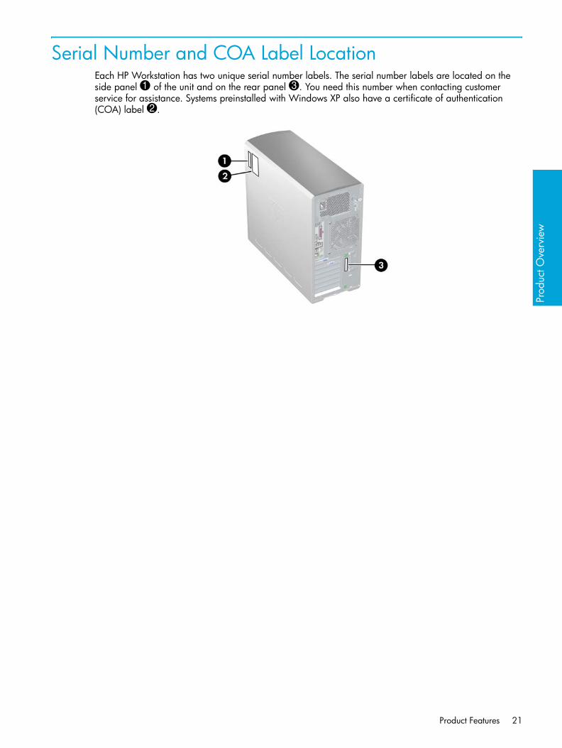
Serial Number and COA Label LocationEach HP Workstation has two unique serial number labels. The serial number labels are located on the side panel 1 of the unit and on the rear panel 3. You need this number when contacting customer service for assistance. Systems preinstalled with Windows XP also have a certificate of authentication (COA) label 2.
Product Features 21

Product SpecificationsThe following table lists the physical dimensions of the HP xw9300 Workstation.
Table 1-4 Physical Characteristics
Weight(dependent on configuration)
19–24kg (42–54 lb)
Tower Dimensions 455mm (17.9 inches) tall210mm (8.3 inches) wide525mm (20.7 inches) deep
Rack Mount Dimensions(top cover and foot removed)
210mm (8.3 inches) tall440mm (17.3 inches) wide525mm (20.7 inches) deep
Product Overview22

Prod
uct O
verv
iew
Power Supply and CoolingThis section contains the following information:
• “Power Supply Specifications” on page 26
• “Power Consumption and Cooling” on page 27
• “System Fans and Airflow” on page 28
• “Resetting the Power Supply” on page 29
Power Supply and Cooling 23

Power Output and CoolingThe HP xw9300 Workstation power supply contains 9 outputs:
• +3.3V—used with PCI, PCI-X, PCI-E, NVIDIA nForce Professional 2000 series MCPs, AMD8131, LS1030, IEEE 1394, Audio, Super I/O, on-board logic
• +5V—used with storage (disk, optical, diskette), PCI, PCI-X, PCI-E, IEEE 1394, NVIDIA nForce Professional 2000 series MCPs, USB, input to on-board regulators (1.2V, 1.5V, 1.8V, and 2.5V), SCSI hard drives, and on-board logic
• +12V-A—used with PCI, PCI-X, PCI-E, IEEE 1394, system fans
• +12V-B—used with storage (disk, optical, floppy)
• +12V-C—used with PCI Express x16 auxiliary connectors
• +12VCPU0—input to onboard regulator that supplies power for CPU0, Mem0, and respective fan
• +12VCPU1—input to onboard regulator that supplies power for CPU1, Mem1, and respective fan
• -12V—used by PCI, PCI-X
• 5VSB—used for sleep circuitry
Table 1-5 Power Supply and Cooling (Voltage)
Voltage Minimum Maximum
3.3V 3.17V 3.47V
5V 4.85V 5.25V
12V CPU0 11.52V 12.6V
12V CPU1 11.52V 12.6V
12V-A 11.52V 12.6V
12V-B 11.52V 12.6V
12V-C 11.52V 12.6V
V12N -11.4V -12.6V
5VSB 4.85V 5.25V
Table 1-6 Power Supply and Cooling (Current)
Current Minimum Operating Continuous Maximum
3.3V 0A 3.1A 25A 35.0A
5V 0A 2.3A 23A 28.0A
12V CPU0 0A 3.1A 12.6A 16.0A
12V CPU1 0A 0A 12.6A 16.0A
12V-A 0A 0A 15A 18.5A
12V-B 0A 0A 3.8A 11.7A
Product Overview24

Prod
uct O
verv
iew
WARNING! Do not exceed 136W of a 5V and 3.3V power combination.
WARNING! Do not exceed 55A (660W) of 12V (CPU0/CPU1/A/B/C) power combination.
WARNING! Do not exceed 700W of total continuous output power.
12V-C 0A 0A 12.5A 14.0A
V12N 0A 0A 0.5A 0.8A
5VSB 0A 0A 2.0A 2A
Table 1-6 Power Supply and Cooling (Current)
Current Minimum Operating Continuous Maximum
Power Supply and Cooling 25

Power Supply SpecificationsThe following table lists the power supply specifications.
Table 1-7 Power Supply Specifications
Full Ranging Input (No Line Select Switch) Yes
Active Power Factor Correction (APFC) (Input Current is nearly half of that of a non-APFC PS)
Yes
Passive Power Factor Correction (PFC) No
Operating Voltage Range 90–264VAC / 118VAC
Rated Voltage Range 100–240VAC
Rated Line Frequency 50–60Hz / 400Hz
Operating Line Frequency Range 47–66Hz / 393–407Hz
Rated Input Current 11.9A / 9.98A
Maximum Rated Power Supply PowerMaximum System Rated Power
750W700W
Heat Dissipation Typical 1184.311 btu/hr Maximum 3656.78 btu/hr
Power Supply Fan 92mm variable speed
PS Size (wide x high x deep) 98mm x 160mm x 200mm
ENERGY STAR Compliant Yes
FEMP Standby Power Compliant(<2W in S5 - Power Off) No
Power Consumption in ES Mode - Suspend to RAM (S3) (Instantly Available PC)
9W
BIST LED Yes
Surge Tolerant Full Ranging Power Supply Withstands power surges up to 2000V
Product Overview26

Prod
uct O
verv
iew
Power Consumption and Cooling The following table shows the power consumption for a typical configuration (based on primary power consumptions):
• Two processors (2.4GHz Opteron)
• 2GB memory (4x512MB)
• Two hard drives (2xSATA 40GB)
• DVD-ROM drive
• PCI Express graphics card (FX1300)
• Diskette drive
• One monitor
a. Approximate values
NOTE: When you turn off your workstation with the power button on the front panel, the power consumption falls below 10W. To reach zero power consumption, either unplug the workstation from the power outlet or use a power strip with a switch.
For additional information on power-saving features, refer to your operating system documentation.
Table 1-8 Power Consumption and Cooling
Input Power Consumptiona @ 120VAC/60Hz
Typical operating mode 347W = 1184 btu/hr
Windows XP idle 262W = 894 btu/hr
Standby mode (S3) 9W = 30.7 btu/hr
Hibernate mode (S4) 7W = 23.9 btu/hr
Power Off (S5) 7W = 23.9 btu/hr
Power Supply and Cooling 27

System Fans and AirflowThe workstation includes one rear system fan, one CPU heatsink for each processor (CPU), one power supply fan, plus a front system fan if two CPUs are installed. For airflow, this system includes a memory airflow duct and a CPU airflow duct, which is required if two CPUs are installed.
Product Overview28

Prod
uct O
verv
iew
Resetting the Power SupplyIf an overload triggers the power supply overload protection, all power is immediately cut. To reset the power supply unit:
1. Disconnect the power cord.
2. Determine what caused the overload and fix the problem.
3. Reconnect the power cord and reboot the workstation.
When you power down the workstation through the operating system, power consumption falls below the low power consumption but does not reach zero. This on/off feature extends the life of the power supply.
Power Supply and Cooling 29

Environmental Specification The following table describes environmental specifications for the HP xw9300 Workstation.
Table 1-9 Environmental Specifications
Temperature (operating) 40° to 95° F (5° to 35° C)
Temperature (non-operating) -40° to 140° F (-40° to 60° C)
Humidity (operating) 8% to 85% RH, non-condensing
Humidity (non-operating) 8% to 90% RH, non-condensing
Shock (operating) 1/2-sine: 40G, 2–3ms
Shock (non-operating) 1/2-sine: 160cm/s, 2–3ms, (~100g)square: 30G, 605cm/s
Vibration (operating) Operating random: 0.5G(RMS), 5–300Hz
Vibration (non-operating) Random: 2.0g(RMS), 10–500Hz
Maximum Altitude (operating) 10,000 ft (3,048m)
Maximum Altitude (non-operating) 30,000 ft (9,144m)
Product Overview30

Prod
uct O
verv
iew
PCI and PCI Express Slot Power SpecificationsThe following table describes the slots, card types, and maximum slot power.
NOTE: If a graphics card requiring more than 75W is installed, HP recommends not using the slot immediately below the graphics card (for example, if PCI Express in slot 1, do not use slot 2). In addition to these slot power specifications, the overall power consumption of the system (including I/O cards, processors, memory, drives) must not exceed 700W.
For hardware specifications of other system components, such as graphics cards or optical drives, refer to the Web site of the specific manufacturer.
Table 1-10 PCI and PCI Express Slot Power Specifications
Slot Slot Type Slot Power (Maximum)
1 PCI Express x16 graphics 150W**
2 PCI 25W*
3 PCI Express x16 graphics 150W**
4 PCI-X 100 25W*
5 PCI-X 100 25W*
6 PCI-X 133 25W*
* In addition to these slot power specifications, the overall power consumption of the system (including I/O cards, processor, and memory) must not exceed 700W.** Includes 75W maximum from the system board connector, and 75W maximum from the auxiliary graphics power connector.
PCI and PCI Express Slot Power Specifications 31

ENERGY STARThe ENERGY STAR® program, a government-backed initiative, promotes energy efficiency by identifying ways to reduce energy consumption. Select HP workstations participate in the ENERGY STAR program.
NOTE: ENERGY STAR is not supported on Linux-based workstations.
For those workstations that support ENERGY STAR and have it enabled, the power management features will be set as follows:
• Monitor—goes into sleep mode after 20 minutes of inactivity.
• System—goes into Standby mode after 20 minutes of inactivity.
• Hard Drive—goes into power savings mode after the system goes into Standby mode.
NOTE: If you have to restore the operating system, reset the ENERGY STAR settings (if applicable) after the restore.
To verify the factory default power settings for your product, select Start > Control Panel and double-click Power Options.
ENERGY STAR ComplianceHP products purchased with the ENERGY STAR configuration are compliant with the U.S. Environmental Protection Agency (EPA) ENERGY STAR Computers Program. The EPA ENERGY STAR configuration does not imply endorsement by the EPA. As an ENERGY STAR Partner, HP has determined that products with the ENERGY STAR configuration meet the ENERGY STAR guidelines for energy efficiency.
The ENERGY STAR Computers Program was created by the EPA to promote energy efficiency and reduce air pollution through more energy-efficient equipment in homes, offices, and factories. HP products achieve this by reducing the power consumption when not being used.
ENERGY STAR on HP Workstations uses ACPI power management. The system can wake as a result of a user action (keyboard or mouse) or from the network or a modem.
The Power Management feature, when used in conjunction with an external ENERGY STAR-compliant monitor, will support the power-down features of the monitor. The Power Management feature allows an external monitor to go into low-power mode when the energy save timeout occurs.
CAUTION: Using the Energy Save Monitor feature with non-ENERGY STAR-compliant monitors might cause video distortion when the Energy Save timeout occurs.
Product Overview32

Insta
lling
or R
esto
ring
the
Ope
ratin
g Sy
stem
2 Installing or Restoring the Operating System
This chapter describes the installation and restoration of the operating system.
• “Installing the Operating System and Software” on page 34
• “Restoring the Operating System” on page 39
• “Protecting the Software” on page 40
• “Ordering Backup Software” on page 41
If the workstation was shipped with a preinstalled OS, it is configured automatically the first time the workstation is turned on.
CAUTION: Adding optional hardware devices to your workstation before the operating system successfully installs can cause errors and prevent the operating system from installing properly.
CAUTION: After the automatic installation has begun, DO NOT TURN OFF THE WORKSTATION UNTIL THIS PROCESS COMPLETES. Turning off the workstation during the installation process might damage the software that runs the system.
33
Installing the Operating System and SoftwareThe following section discusses the operating system and HP software installation procedures.
• “Microsoft Windows XP Professional” on page 34
• “Linux-Preinstalled Workstations” on page 35
• “Linux-Enabled Workstations” on page 37
• “HP Software” on page 38
Microsoft Windows XP ProfessionalThe first time you turn on your workstation, you are prompted to select a language for the operating system. After selecting the language, read and follow the instructions on the screen to complete the installation of the operating system. This takes approximately 10 minutes, depending on the system hardware configuration. During the process, do not turn off your workstation unless you are directed to do so.
Installing or Upgrading Device DriversTo install hardware devices, such as a printer, display adapter, or network adapter after the operating system is installed, the operating system needs access to the appropriate software drivers for the devices.
To copy the drivers to your system, perform one of the following actions:
• Copy the drivers from the CD that was supplied with the peripheral device because manufacturers usually send drivers on the CD.
• Go to the Help & Support Center installed on your system (on most factory-installed Windows XP operating systems), click Start > Help & Support. Click the icon above HP Software & Drivers Download and review or select available updates.
• Visit the HP Support Web site:
a. Go to http://www.hp.com/go/workstationsupport.
b. Select your HP Workstation from the list.
c. In the “I would like to” section, click download drivers and software.
d. In the “select operating system” section, select your OS.
e. Locate the driver and click download next to your desired file. Follow the on-screen instructions to complete installation.
• Visit the Web site of the manufacturer of the peripheral device if no drivers can be found with the other methods.
Creating a Restore DisketteTo create a restore diskette for Windows XP, select Start > All Programs > Accessories > System Tools > System Restore and follow the on-screen instructions.
Installing or Restoring the Operating System34

Insta
lling
or R
esto
ring
the
Ope
ratin
g Sy
stem
Linux-Preinstalled WorkstationsIf you have a Linux-preinstalled HP Workstation, follow the instructions in this section to set up your OS and software.
After the boot process completes, you can view additional HP Linux documentation by opening your Internet browser (the browser is automatically set to use the local HP documentation page as its default). You can also access Linux Web links for Red Hat (Internet access required) by using your Internet browser.
NOTE: For additional information on setting up Linux-preinstalled or Linux-enabled workstations, refer to the HP User Manual for Linux, which is located at http://www.hp.com/support/linux_user_manual. For more information about HP and Linux, visit http://www.hp.com/linux.
Starting the Linux Operating SystemThe first time the workstation is booted, the Red Hat First Boot utility displays. This program enables you to enter your password, network, graphics, time, and keyboard settings for your workstation.
CAUTION: After the automatic installation has begun, DO NOT TURN OFF THE WORKSTATION UNTIL THE PROCESS IS COMPLETE. Turning off the workstation during the installation process might damage the software that runs the workstation or prevent its proper installation.
NOTE: When you enable the YPBind feature in the Network tab of the Linux Setup Tool, you might get a blank screen for 15–30 seconds after you have selected, saved all of your settings, and have exited the utility. This is normal behavior. The boot process continues its execution after the screen returns.
Restoring the Linux Operating System
NOTE: To restore the Linux OS, the HP Driver CD and Red Hat box set are required. To get any new enhancements, download the latest HP Driver CD.
NOTE: Linux does not support mixed drive types for a manufacturing preload. When restoring the operating system, mixed drive types can be handled with the restoring media.
Downloading the Latest HP Driver CD
1. Download the ISO image to a local hard drive from the HP support Web site at http://www.hp.com/go/workstationsupport.
a. Select your HP Workstation from the list.
b. Click download drivers and software.
c. Select the Linux OS that matches your box set.
d. Select the latest version from the Utility Tools section.
e. Download and unpack it (tar zxvf filename.tgz).
Installing the Operating System and Software 35

2. Copy the ISO image to CD-R bootable media. On another Linux workstation, use the cdrecord utility. Identify the device address for the CD burner (cdrecord --scanbus).The default is usually 2, 0, 0.
Example:cdrecord -v -eject dev=2,0,0 CD0_golden.iso
Installing with the HP Driver CDTo install with the HP Driver CD:
1. Boot the workstation from the Red Hat box set Binary CD 1.
2. Insert the Linux operating system CDs from the Red Hat box set as prompted.
3. Continue following the prompts until the operating system is successfully installed.
4. Configure the X server to start on reboot.
5. Reboot the workstation.
6. Follow the prompts to set up your system with the Red Hat First Boot utility.
7. When prompted in First Boot to add additional CDs, insert the HP Driver CD into the CD-ROM tray of the workstation.
8. Click Install next to “Additional CDs.”The HP Driver CD window opens.
9. Click Press to begin install...
10.When the install is done, you will have two options, “Reboot now...” on the left side and “Press to continue, reboot later...” on the right side. Click Reboot now...
Upgrading Device DriversIf you must upgrade a Linux device driver, visit the HP Workstation support Web site athttp://www.hp.com/go/workstationsupport.
To install hardware devices, such as a printer, a display adapter, or a network adapter after the operating system is installed, the operating system needs access to the appropriate software drivers for the devices. Device drivers are usually provided on a CD supplied with the peripheral device.
Some existing peripheral devices might not have been shipped with drivers developed for Linux. To locate the most current device drivers:
1. Go to http://www.hp.com/go/workstationsupport.
2. Select your HP Workstation from the list.
3. Click download drivers and software.
4. Select your Linux OS version.
5. Scroll down and download the desired driver.
If no driver is found, visit the Web site of the manufacturer of the peripheral device.
Installing or Restoring the Operating System36

Insta
lling
or R
esto
ring
the
Ope
ratin
g Sy
stem
Linux-Enabled WorkstationsLinux-enabled HP Workstations require the HP Installer Kit for Linux and the purchase of a Red Hat box set. The Installer Kit includes the HP CDs necessary to complete the installation of all versions of the Red Hat box set that have been verified to work on HP Workstation hardware.
Verifying Hardware CompatibilityTo see which Linux versions have been verified to work on HP Workstation hardware:
1. Go to http://www.hp.com/support/workstation_manuals.
2. Select your HP Workstation model.
3. Click the Hardware Support Matrix for Linux link.
Installing the Linux Operating SystemTo install the Linux operating system on your Linux-enabled system:
1. Follow the instructions for “Restoring the Linux Operating System” on page 35 in the previous section.
2. Follow the instructions for “Starting the Linux Operating System” on page 35 in the previous section.
NOTE: For more information on setting up Linux-preinstalled or Linux-enabled HP Workstations, refer to the HP User Manual for Linux, which is located at http://www.hp.com/support/linux_user_manual. For more information about HP and Linux, visit http://www.hp.com/linux.
Upgrading Device DriversIf you must install new drivers, go to http://www.hp.com/go/workstationsupport or refer to “Upgrading Device Drivers” on page 36 in the previous section for more instructions.
Installing the Operating System and Software 37

HP SoftwareThe following HP software is installed the first time the HP Workstation is turned on:
• Computer Setup (F10) Utilities and diagnostic features
• HP Support Software including device drivers
• HP Client Manager Software (available for download from http://www.hp.com/go/easydeploy)
• System Software Manager (available for download from http://www.hp.com/go/ssm)
• Power Management Setup with Energy Saver features (not supported on Linux)
• Security Management tools
• Software Support Management tools
Certain drivers and utilities are available only in selected languages. You can obtain the latest version of these files, in English and selected other languages, in one of four ways:
• Support Software CD
• HP Web site at http://www.hp.com
• Restore Plus! CD, which is supplied with Windows-based workstations
• HP Workstations Red Hat Linux with HP Additions CD, which is supplied with Linux-based workstations
NOTE: Additional HP software might be required in certain situations.
Installing or Restoring the Operating System38

Insta
lling
or R
esto
ring
the
Ope
ratin
g Sy
stem
Restoring the Operating SystemTo restore the original Windows operating system and factory-installed software, insert the Restore Plus! CD that came with your HP Workstation. Carefully read and follow the instructions provided with the Restore Plus! CD.
NOTE: If you restore your system using the Restore Plus! CD, some settings, such as your power management settings (such as the Energy Star® settings), will need to be reapplied.
In some scenarios, such as if the system is bootable to Windows, an alternative method is to use the System Restore feature included with Windows XP. To restore Windows to a previous state, select Start > All Programs > Accessories > System Tools > System Restore and follow the on-screen instructions.
For more information about restoring the Linux OS or software, see “Restoring the Linux Operating System” on page 35.
Restoring the Operating System 39

Protecting the SoftwareTo protect software from loss or damage, keep a backup copy of all system software, applications, and related files stored on the hard drive. See the operating system or backup utility documentation for instructions on making backup copies of data files.
Installing or Restoring the Operating System40

Insta
lling
or R
esto
ring
the
Ope
ratin
g Sy
stem
Ordering Backup SoftwareAll software that shipped with the workstation, including the Restore Plus! CD, can be ordered from HP as a single set, or you can order the various software packages separately.
NOTE: Before calling HP to order the software, be sure to have the serial number of the workstation available. See “Serial Number and COA Label Location” on page 21.
Ordering Backup Software 41

Installing or Restoring the Operating System42

Syste
m M
anag
emen
t
3 System Management
This section describes the various tools and utilities that allow for the system management of the workstation.
• “Computer Setup (F10)” on page 44
• “Desktop Management” on page 54
43

Computer Setup (F10)This section contains the following information to help you use Computer Setup.
• “BIOS ROM” on page 45
• “Using Computer Setup (F10)” on page 46
• “Computer Setup Menu” on page 47
The Computer Setup (F10) utilities enable you to:
• Change current settings from the factory default settings and set, view, change, or verify the system configuration, including settings for processor, graphics, memory, audio, storage, communications, and input devices.
• Determine if all of the devices installed on the workstation are recognized by the system and functioning properly.
• Determine information about the operating environment of the workstation.
• Solve system configuration errors detected but not automatically fixed during the Power-On Self-Test (POST).
• Establish and manage passwords and other security features.
• Establish and manage energy-saving timeouts (not supported for Linux platforms).
• Modify or restore factory default settings.
• Set the system date and time.
• Modify the boot order of bootable devices, such as hard drives, diskette drives, optical drives, or LS-120 drives.
• Configure the boot priority of SATA and SCSI hard drive controllers.
• Enable Quick Boot, which is faster than Full Boot but does not run all of the diagnostic tests run during a Full Boot. You can set your system to:
• always Quick Boot (default)• periodically Full Boot (from every 1 to 30 days)• always Full Boot
• Enable or disable Network Server Mode, which enables the workstation to boot the operating system when the power-on password is enabled with or without a keyboard or mouse attached. When attached to the system, the keyboard and mouse remain locked until the power-on password is entered.
• Select POST Messages Enabled or Disabled to change the display status of POST messages. POST Messages Disabled suppresses most POST messages, such as memory count, product name, and other non-error text messages. If a POST error occurs, the error is displayed regardless of the mode selected. To manually switch to POST Messages Enabled during POST, press any key (except F1 through F12).
• Establish an Ownership Tag, the text of which is displayed each time the system is turned on or restarted.
• Enter the Asset Tag or property identification number assigned by your company to this workstation.
• Enable power-on password prompting during system restarts (warm boots) as well as during power-on.
• Secure the integrated I/O functionality, including the serial, USB, or parallel ports, audio, or embedded NIC, so that the I/O functionality cannot be used until they are unsecured.
• Enable or disable removable media boot ability.
• Enable or disable removable media write ability (when supported by hardware).
• Replicate your system setup by saving system configuration information on diskette and restoring it on one or more workstations.
System Management44

Syste
m M
anag
emen
t
• Execute self-tests on specified SATA hard drives (when supported by the drive).
BIOS ROMThe Basic Input/Output System (BIOS) of the computer is a collection of machine language programs stored as firmware in read-only memory (ROM). The BIOS ROM includes such functions as POST, PCI device initialization, Plug 'n Play (PnP) support, power management activities, and the Setup utility. The firmware contained in the BIOS ROM supports the following systems and specifications:
• Dual AMD Opteron 2xx series
• Memory for DDR333 and DDR400
• Hyper-transport setup and initialization
• Chipset (includes NVIDIA nForce4 Pro, AMD 8131 PCI-X bridge, all applicable device support in chipsets, SCSI LSI 1030, SIO5)
• ACPI 1.0b with ACPI 2.0 extensions for 64-bit support, according to Microsoft Logo Requirements. S1, S3, S4, S5 and S5 with Remote Power On by way of LAN wake packet.
• SMBIOS Spec 2.3.4 implementation and field definitions that accurately represent hardware configurations and OEM ID
• BBS 1.01
• DOS and Windows based BIOS flash tools
• Microsoft SDG 3.0 compliant as applicable
• PMM 1.01 as applicable
• MPS 1.4 as applicable
• PXE 2.1
• USB 1.1/USB 2.0
• PCI 2.2 or later
• “El Torito” Bootable CD 1.0
Computer Setup (F10) 45

Using Computer Setup (F10)You can only open Computer Setup by turning on the workstation or restarting the system. To access the Computer Setup Utilities menu:
1. Turn on or restart the workstation.
2. Press the F10 key as soon as the monitor light turns green.
NOTE: f you do not press the F10 key at the appropriate time, you must restart the workstation and press and hold the F10 key again to access the utility.
3. Select your language from the list and press Enter. In the Computer Setup Utilities menu, four headings are displayed: File, Storage, Security, and Advanced.
4. Use the arrow (left and right) keys to select the appropriate heading. Use the arrow (up and down) keys to select the option you want, then press Enter.
5. To apply and save changes, select File > Save Changes and Exit.
• If you have made changes that you do not want applied, select Ignore Changes and Exit.
• To reset to factory settings, select Set Defaults and Exit. This option restores the original factory system defaults.
CAUTION: Do NOT turn the workstation power OFF while the ROM is saving your Computer Setup F10 changes because the CMOS could become corrupted. After you exit the F10 Setup screen, it is safe to turn off all power to the workstation.
System Management46

Syste
m M
anag
emen
t
Computer Setup MenuNOTE: The following content is subject to change with new firmware releases, so your menu might be than the following table.
Table 3-11 Computer Setup Menu Descriptions
Heading Option Description
File System Information
Lists product name, processor type/speed/stepping, cache size (L1/L2), system ROM family and version, installed memory size, chassis serial number, integrated MAC for enabled or embedded NIC (if applicable), and asset tracking number.
About Displays copyright information.
Set Time and Date
Enables you to set system time and date.
Save to Diskette
Saves system configuration, including CMOS, to a formatted, blank 1.44-MB diskette in the CPQsetup.txt file. Save/Restore for is supported.
Restore from Diskette
Restores system configuration from a diskette.
Set Defaults and Exit
Restores factory default settings, which includes clearing any established passwords.
Ignore Changes and Exit
Exits Computer Setup without applying or saving any changes.
Save Changes and Exit
Saves changes to system configuration and exits Computer Setup.
Computer Setup (F10) 47

Storage Device Configuration
Lists all installed non-SCSI storage devices.SCSI storage drives will not be listed in Computer Setup (F10).SATA storage drives will not be listed in this menu. When a device is selected, detailed information and options are displayed. The following options might be presented:
Hard DiskIdentifies the hard disk drives in the system.
CD-ROMIdentifies the optical drives in the system.
Diskette Type (for legacy diskette drives only)Identifies the highest capacity media type accepted by the diskette drive. Options are 3.5" 1.44 MB, 5.25" 1.2 MB, and Not Installed.
Default Values
Transfer Mode (IDE devices only)Specifies the active data transfer mode. Options (subject to device capabilities) are PIO 0, Max PIO, Enhanced DMA, Ultra DMA 0, and Max UDMA.
CAUTION: A new Automatic option has been added to allow for BIOS to automatically determine the translation mode used to configure a previously formatted SATA or USB mass storage device. This prevents you from having to know how the mass storage device was previously formatted.
Ordinarily, the translation mode selected automatically by the BIOS should not be changed. If the selected translation mode is not compatible with the translation mode that was active when the disk was partitioned and formatted, the data on the disk will be inaccessible.
Table 3-11 Computer Setup Menu Descriptions (continued)
Heading Option Description
System Management48
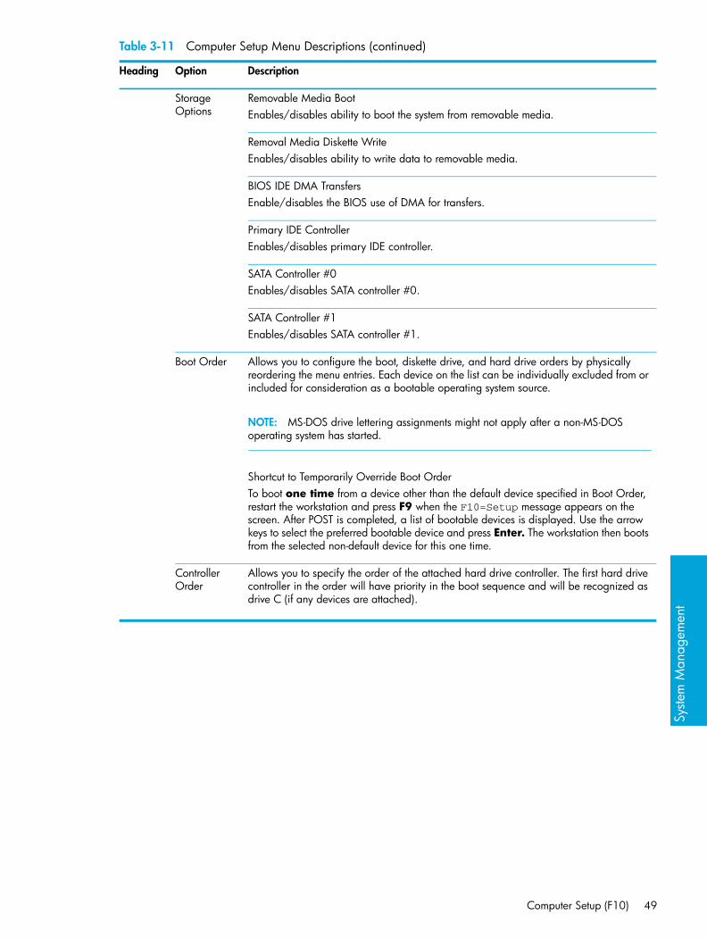
Syste
m M
anag
emen
t
Storage Options
Removable Media BootEnables/disables ability to boot the system from removable media.
Removal Media Diskette WriteEnables/disables ability to write data to removable media.
BIOS IDE DMA TransfersEnable/disables the BIOS use of DMA for transfers.
Primary IDE ControllerEnables/disables primary IDE controller.
SATA Controller #0Enables/disables SATA controller #0.
SATA Controller #1Enables/disables SATA controller #1.
Boot Order Allows you to configure the boot, diskette drive, and hard drive orders by physically reordering the menu entries. Each device on the list can be individually excluded from or included for consideration as a bootable operating system source.
NOTE: MS-DOS drive lettering assignments might not apply after a non-MS-DOS operating system has started.
Shortcut to Temporarily Override Boot OrderTo boot one time from a device other than the default device specified in Boot Order, restart the workstation and press F9 when the F10=Setup message appears on the screen. After POST is completed, a list of bootable devices is displayed. Use the arrow keys to select the preferred bootable device and press Enter. The workstation then boots from the selected non-default device for this one time.
Controller Order
Allows you to specify the order of the attached hard drive controller. The first hard drive controller in the order will have priority in the boot sequence and will be recognized as drive C (if any devices are attached).
Table 3-11 Computer Setup Menu Descriptions (continued)
Heading Option Description
Computer Setup (F10) 49

Security Setup Password
Allows you to set and enable setup (administrator) password.
NOTE: If the setup password is set, it is required to change Computer Setup options, flash the ROM, and make changes to certain PnP settings under Windows.
Power-On Password
Allows you to set and enable power-on password.
Smart Cover Allows you to disable cover removal sensor or to notify user if sensor has been activated.
Device Security
Serial PortSpecifies if device is available or hidden to the OS.
All USB PortsSpecifies if device is available or hidden to the OS.
Front USB PortsSpecifies if device is available or hidden to the OS.
IEEE 1394 ControllerSpecifies if device is available or hidden to the OS.
Network ControllerSpecifies if device is available or hidden to the OS.
SCSI ControllerSpecifies if device is available or hidden to the OS.
Network Service Boot
Enables/disables the ability to boot to the network by way of the F12 key or the boot order.
System IDs Allows you to set:
• Asset tag (16-byte identifier) and ownership tag (80-byte identifier displayed during POST).
• Chassis serial number or Universal Unique Identifier (UUID) number. The UUID can only be updated if the current chassis serial number is invalid. (These ID numbers are normally set in the factory and are used to uniquely identify the system.)
• Keyboard locale setting (for example, English or German) for System ID entry.• Monitor tracking
Data Execution Prevention
Enables/disables a mode that helps prevent OS security breaches.
Table 3-11 Computer Setup Menu Descriptions (continued)
Heading Option Description
System Management50

Syste
m M
anag
emen
t
Advanced**
Boot Allows you to set:• POST Mode (QuickBoot, FullBoot, or FullBoot every 1–30 days).
• POST Messages (enable/disable).
• F9 Prompt (enable/disable). Enabling this feature will display the text F9=Boot Menu during POST. Disabling this feature prevents the text from being displayed. However, pressing the F9 key will still access the Shortcut Boot [Order] Menu screen.
• F10 Prompt (enable/disable). Enabling this feature displays the text F10=Setup during POST. Disabling this feature prevents the text from being displayed but pressing F10 still accesses the Setup screen.
• F12 Prompt (enable/disable). Enabling this feature displays the text F12=Network Service Boot during POST. Disabling this feature prevents the text from being displayed but pressing F12 still forces the system to attempt booting from the network.
• Option ROM* prompt (enable/disable). Enabling this feature causes the system to display a message before loading options ROMs.
• POST Delay (in seconds) (enable/disable). Enabling this feature adds a user-specified delay to the POST process. This delay is sometimes needed for hard disks on some PCI cards that spin up slowly—so slowly that they are not ready to boot by the time POST is finished. The POST delay also gives you more time to select F10 to enter Computer Setup (F10).
• Num Lock State at Power-On (enable/disable). Enabling this feature automatically turns on Num Lock at startup.
Power/Sleep/Wake
Options:• Remote Wakeup Boot Source.• After Power Loss (on/off).• S5 Wake on LAN (enable/disable).• ACPI S3* Support (enable/disable). S3 is an advanced configuration and power
interface (ACPI) sleep state that some add-in hardware options might not support.
NOTE: ACPI S3 selections are supported on select models only. If the ACPI S3 support option is not presented, the other ACPI S3 options (ACPI S3 Hard disk Reset, and ACPI S3 PS2 Mouse Wakeup) will not be available.
• ACPI S3 Video REPOST* (enable/disable). This feature reruns the video option ROM on a boot from the S3 state.
• ACPI S3 Hard Disk Reset* (enable/disable). Resets the hard disk on a boot from the S3 sleep state.
• ACPI S3 PS2 Mouse Wakeup* (enable/disable). Allows the mouse to wake the system from the S3 sleep state.
• Unique Sleep State Blink Rates (enable/disable). Allows you to choose an LED blink pattern that uniquely identifies each sleep state.
Table 3-11 Computer Setup Menu Descriptions (continued)
Heading Option Description
Computer Setup (F10) 51

Processors Enable/disable Processor Cache and Coherent HT Speed*.
NOTE: You can set the Hyper Transport Speed between the CPUs to one of the following values: 200, 400, 600, 1000, and Auto.
*This option is only available on systems with two processors.
Chipset/Memory
Enable/disable ECC support, Memory scrubbing, Memory remapping, and PCI SERR# generation.
Onboard Devices
Enables you to set resources for or disable onboard system devices (serial ports, USB ports, diskette controllers, and so on).
Device Options
Allows you to enable/disable:• SATA Option ROM• SATA RAID
• When SATA RAID is enabled, the following items are displayed:SATA PORT # to 0 RAIDYou must enable the port before using RAID.SATA PORT # to 1 RAIDYou must enable the port before using RAID.SATA PORT # to 2 RAIDYou must enable the port before using RAID.SATA PORT # to 3 RAIDYou must enable the port before using RAID.
• SCSI Option ROM• Network Controller Option
Thermal Enable/disable full speed chassis fans.
PCI VGA Configuration
NVIDIA VGA controller*Specifies if controller is Primary VGA device/Non-boot device.NVIDIA VGA controller**Specifies if controller is Primary VGA device/Non-boot device.* This controller refers to slot 1. **This controller refers to slot 3, which is only available in a system with two graphics cards.
Slot 1 (PCI Express x 16)
Configures the option ROM.
Slot 2 (PCI) Configures the option ROM and latency timer.
Slot 3 (PCI Express x 16)
Configures the option ROM.
Slot 4 (PCI-X 100)
Configures the option ROM and latency timer.
Slot 5 (PCI-X 100)
Configures the option ROM and latency timer.
Table 3-11 Computer Setup Menu Descriptions (continued)
Heading Option Description
System Management52

Syste
m M
anag
emen
t
Slot 6 (PCI-X 133)
Configures the option ROM, latency timer, and PCI x4 function check**.
*Available on select models.**These options should be used by advanced users only.
Table 3-11 Computer Setup Menu Descriptions (continued)
Heading Option Description
Computer Setup (F10) 53

Desktop ManagementHP Client Management Solutions (available for download from http://www.hp.com/go/easydeploy) provides standards-based solutions for managing and controlling workstations in a networked environment. This section summarizes the capabilities and features of the key components of desktop management:
• “Initial Configuration and Deployment” on page 55
• “Remote System Installation” on page 56
• “Software Updating and Management” on page 57
• “ROM Flash” on page 59
• “Asset Tracking and Security” on page 64
• “Fault Notification and Recovery” on page 71
NOTE: Support for specific features described in this section might vary by model or software version.
System Management54
Syste
m M
anag
emen
t
Initial Configuration and DeploymentThe workstation comes with a preinstalled system software image. After a brief software “unbundling” process, the workstation is ready to use.
You might prefer to replace the preinstalled software image with a customized set of system and application software. There are several methods for deploying a customized software image. They include:
• Installing additional software applications after unbundling the preinstalled software image.
• Using software deployment tools, such as Altiris Deployment Solutions™, to replace the preinstalled software with a customized software image.
• Using a disk cloning process to copy the contents from one hard drive to another.
The best deployment method depends on your information technology environment and processes. The PC Deployment section of the HP Lifecycle Solutions Web site (http://whp-sp-orig.extweb.hp.com/country/us/en/solutions.html) provides information to help you select the best deployment method.
The Restore Plus! CD, ROM-based setup, and ACPI hardware provide further assistance with recovery of system software, configuration management and troubleshooting, and power management.
Desktop Management 55

Remote System InstallationRemote System Installation lets you start and set up your system using the software and configuration information located on a network server. This feature is usually used as a system setup and configuration tool, and can be used for the following tasks:
• Deploying a software image on one or more new PCs
• Formatting a hard drive
• Installing application software or drivers
• Updating the operating system, application software, or drivers
To initiate Remote System Installation, press F12 when the F12=Network Service Boot message appears in the lower-right corner of the HP logo screen. Follow the on-screen instructions to continue the process. The default boot order is a BIOS configuration setting that can be changed to always attempt to PXE boot.
HP and Altiris have partnered to provide tools designed to make the task of corporate PC deployment and management easier and less time-consuming, ultimately lowering the total cost of ownership and making HP PCs the most manageable client PCs in the enterprise environment.
System Management56
Syste
m M
anag
emen
t
Software Updating and ManagementHP provides several tools for managing and updating software on desktops and workstations—HP Client Manager Software, Altiris Client Management Solutions, System Software Manager, Proactive Change Notification, and Subscriber’s Choice.
HP Client Manager SoftwareHP Client Manager Software (HP CMS) assists HP customers in managing the hardware aspects of their client workstations with features that include:
• Detailed views of hardware inventory for asset management
• PC health check monitoring and diagnostics
• Proactive notification of changes in the hardware environment
• Web-accessible reporting of business critical details, such as machines with thermal warnings, memory alerts, and more
• Remote updating of system software such as device drivers and ROM BIOS
• Remote changing of boot order
• Configuring the system BIOS settings
For more information on the HP Client Manager, visit http://www.hp.com/go/im.
Altiris Client Management SolutionsHP and Altiris have partnered to provide comprehensive, tightly integrated systems management solutions to reduce the cost of owning HP client PCs. HP Client Manager Software is the foundation for additional Altiris Client Management Solutions that address:
• Inventory and Asset Management
• SW license compliance• PC tracking and reporting• Lease contract, fixing asset tracking
• Deployment and Migration
• Microsoft Windows XP Professional or Home Edition migration• System deployment• Personality migrations
• Help Desk and Problem Resolution
• Managing help desk tickets• Remote troubleshooting• Remote problem resolution• Client disaster recovery
• Software and Operations Management
• Ongoing desktop management• HP system SW deployment• Application self-healing
Desktop Management 57

For more information and details on how to download a fully-functional 30-day evaluation version of the Altiris solutions, visit http://h18000.www1.hp.com/im/prodinfo.html#deploy.
For more information, visit http://www.hp.com/go/easydisplay.
System Software ManagerSystem Software Manager (SSM) is a utility that lets you update system-level software on multiple systems simultaneously. When executed on a PC client system, SSM detects both hardware and software versions, then updates the appropriate software from a central repository, also known as a file store. Driver versions that are supported by SSM are denoted with a special icon on the software, the driver download Web site, and on the Support Software CD. To download the utility or to obtain more information on SSM, visit http://www.hp.com/go/ssm.
Proactive Change NotificationThe Proactive Change Notification program uses the Subscriber's Choice Web site to proactively and automatically:
• Send you Proactive Change Notification (PCN) e-mails informing you of hardware and software changes to most commercial workstations and servers, up to 60 days in advance.
• Send you e-mail containing Customer Bulletins, Customer Advisories, Customer Notes, Security Bulletins, and Driver alerts for most commercial workstations and servers.
You create your own profile to ensure that you only receive the information relevant to a specific IT environment. To learn more about the Proactive Change Notification program and create a custom profile, visit http://www.hp.com/go/pcn.
Subscriber’s ChoiceSubscriber’s Choice is a client-based service from HP. Based on your profile, HP will supply you with personalized product tips, feature articles, driver and support alerts/notifications, or both. Subscriber’s Choice Driver and Support Alerts/Notifications will deliver e-mails notifying you that the information you subscribed to in your profile is available for review and retrieval. To learn more about Subscriber’s Choice and create a custom profile, visit http://www.hp.com/go/pcn.
System Management58

Syste
m M
anag
emen
t
ROM FlashThe workstation comes with a programmable flash read-only memory (ROM). By establishing a setup password in the Computer Setup (F10) Utility, you can protect the ROM from being unintentionally updated or overwritten. This is important to ensure the operating integrity of the workstation. If you need or want to upgrade the ROM, you can:
• Order an upgraded ROMPaq diskette from HP.
• Download the latest ROMPaq images from HP driver and support page, http://www.hp.com/support/files.
CAUTION: For maximum ROM protection, be sure to establish a setup password. The setup password prevents unauthorized ROM upgrades. System Software Manager allows the system administrator to set the setup password on one or more PCs simultaneously. For more information, visit http://www.hp.com/go/ssm.
CAUTION: The boot block jumper at E14 MUST NOT be installed during a ROM flash operation unless specified by HP. Normally, the boot block jumper is completely removed or installed only on E14 pin 2. Installing the boot block jumper enables changing the boot block and defeats the FailSafe Boot Block ROM protection.
Remote ROM FlashRemote ROM Flash allows the system administrator to safely upgrade the ROM on remote HP workstations directly from the centralized network management console. Enabling the system administrator to perform this task remotely on multiple workstations and personal computers results in a consistent deployment of and greater control over HP PC ROM images over the network. It also results in greater productivity and lower total cost of ownership.
The workstation must be powered on to take advantage of Remote ROM Flash.
For more information on Remote ROM Flash, see the HP Client Manager Software or System Software Manager at http://h18000.www1.hp.com/im/prodinfo.html.
HPQFlashThe HPQFlash utility is used to locally update or restore the system ROM on individual PCs through a Windows operating system.
For more information on HPQFlash, visit http://www.hp.com/support/files and enter the name of the workstation when prompted.
FailSafe Boot Block ROMThe FailSafe Boot Block ROM allows for system recovery in the unlikely event of a ROM flash failure; for example, if a power failure were to occur during a ROM upgrade. The Boot Block is a flash-protected section of the ROM that checks for a valid system ROM flash when power to the system is turned on.
• If the system ROM is valid, the system starts normally.
• If the system ROM fails the validation check, the FailSafe Boot Block ROM provides enough support to start the system from a ROMPaq diskette, which will program the system ROM with a valid image.
Desktop Management 59

NOTE: Some models also support recovery from a ROMPaq CD. ISO ROMPaq images are included with selected models in the downloadable ROM softpaqs.
When the boot block detects an invalid system ROM, the power LED blinks RED eight times, one every second, followed by a 2-second pause. Also, eight simultaneous beeps will be heard. A Boot Block recovery mode message is displayed on the screen (some models).
To recover the system after it enters Boot Block recovery mode:
1. If there is a diskette in the diskette drive or a CD in the CD drive, remove the diskette and CD and turn off the power.
2. Insert a ROMPaq diskette into the diskette drive or, if permitted on this workstation, a ROMPaq CD into the CD drive.
3. Turn on the workstation.
If no ROMPaq diskette or ROMPaq CD is found, you will be prompted to insert one and restart the workstation.
If a setup password has been established, the Caps Lock light will turn on (on PS/2 keyboard only) and you will be prompted to enter the password.
4. Enter the setup password.
If the system successfully starts from the diskette and successfully reprograms the ROM, then the three keyboard lights will turn on. A rising tone series of beeps also signals successful completion.
5. Remove the diskette or CD and turn the power off.
6. Turn the power on again to restart the workstation.
The following table lists the various keyboard light combinations used by the Boot Block ROM (when a PS/2 keyboard is attached to the workstation), and explains the meaning and action associated with each combination.
Table 3-12 Keyboard Light Combinations Used by Boot Black ROM
FailSafe BootBlock Mode
Keyboard LED Activity State/Message
Num Lock On ROMPaq diskette or ROMPaq CD not present, is bad, or drive not ready.
Caps Lock On Enter password.
Num, Caps, Scroll Lock
Blink On in sequence, one at a time–N,C, SL
Keyboard locked in network mode.
Num, Caps, Scroll Lock
On Boot Block ROM Flash successful. Turn power off, then on to reboot.
NOTE: Diagnostic lights do not flash on USB keyboards
System Management60

Syste
m M
anag
emen
t
Replicating the SetupThe following procedures give an administrator the ability to easily copy one setup configuration to other workstations of the same model. This allows for faster, more consistent configuration of multiple workstations.
NOTE: Both procedures require a diskette drive.
NOTE: To collect and replicate BIOS settings on multiple computers, use System Software Manager or HP Client Manager Software. For more information, visit http://www.hp.com/go/easydeploy.
Copying to a Single Workstation
CAUTION: A setup configuration is model-specific. File system corruption might result if source and target workstations are not the same model. For example, do not copy the setup configuration from an HP xw4200 Workstation to an HP xw9300 Workstation.
1. Select a setup configuration to copy. Turn off the workstation.
2. Turn on the workstation.
3. As soon as the workstation is turned on, press and hold the F10 key until you enter Computer Setup. Press Enter to bypass the title screen, if necessary.
NOTE: If you do not press the F10 key at the appropriate time, you must restart the workstation and press and hold the F10 key again to access the utility.
If you are using a PS/2 keyboard, you might see a Keyboard Error message—disregard it.
4. If you are using a diskette, insert it now.
5. Click File > Save to Diskette. Follow the instructions on the screen to create the configuration diskette.
6. Turn off the workstation to be configured and insert the configuration diskette.
7. Turn on the workstation to be configured.
8. As soon as the workstation is turned on, press and hold the F10 key until you enter Computer Setup. Press Enter to bypass the title screen, if necessary.
9. Click File > Restore from Diskette and follow the on-screen instructions.
10.Restart the workstation when the configuration is complete.
Copying to Multiple Workstations
CAUTION: A setup configuration is model-specific. File system corruption might result if source and target workstations are not the same model. For example, do not copy the setup configuration from a HP Workstation xw4200 to HP xw9300 Workstation.
This method takes a little longer to prepare the configuration diskette, but copying the configuration to target workstations is significantly faster.
Desktop Management 61

NOTE: A bootable diskette is required for this procedure. If Windows XP is not available to create a bootable diskette, use the method for copying to a single workstation instead (see “Copying to a Single Workstation” on page 61).
1. Create a bootable diskette.
2. Select a setup configuration to copy.
3. Download a BIOS utility for replicating setup (repset.exe) and copy it onto the configuration diskette. To obtain this utility, go to http://welcome.hp.com/support/files and enter the model number of the workstation.
4. On the configuration diskette, create an autoexec.bat file containing the following command: repset.exe.
5. Restart the workstation.
6. As soon as the workstation is turned on, press and hold the F10 key until you enter Computer Setup. Press Enter to bypass the title screen, if necessary.
NOTE: If you do not press the F10 key at the appropriate time, you must restart the workstation and press and hold the F10 key again to access the utility.
If you are using a PS/2 keyboard, you may see a Keyboard Error message—disregard it.
7. Insert the diskette now.
8. Click File > Replicated Setup > Save to Diskette. Follow the on-screen instructions to create the configuration diskette.
9. Turn off the workstation to be configured. Insert the configuration diskette and turn the workstation on. The configuration utility will run automatically.
10.Restart the workstation when the configuration is complete.
Dual-State Power ButtonWith Advanced Configuration and Power Interface (ACPI) enabled, the power button can function either as an on/off switch or as a Standby button. The Standby feature does not completely turn off power, but instead causes the workstation to enter a low-power standby state. This allows you to power down quickly without closing applications and to return quickly to the same operational state without any data loss.
To change the power button configuration:
1. Click Start > Control Panel > Power Options.
2. In the Power Options Properties, select the Advanced tab.
3. In the Power Button section, select Standby.
After configuring the power button to function as a Standby button, press the power button to put the system in a very low power state (Standby). Press the button again to quickly bring the system out of Standby to full power status. To completely turn off all power to the system, press and hold the power button for four seconds.
CAUTION: Do not use the power button to turn off the workstation unless the system is not responding; turning off the power without operating system interaction could cause damage to or loss of data on the hard drive.
System Management62

Syste
m M
anag
emen
t
World Wide Web SiteHP engineers rigorously test and debug software developed by HP and third-party suppliers, and develop operating system specific support software, to ensure performance, compatibility, and reliability for HP workstations.
When making the transition to new or revised operating systems, it is important to implement the support software designed for that operating system. If you plan to run a version of Microsoft Windows that is different from the version included with the workstation, you must install corresponding device drivers and utilities to ensure that all features are supported and functioning properly.
HP has made the task of locating, accessing, evaluating, and installing the latest support software easier. You can download the software from http://www.hp.com/support.
The Web site contains the latest device drivers, utilities, and flashable ROM images needed to run the latest Microsoft Windows operating system on the HP workstation.
Building Blocks and PartnersHP management solutions integrate with other systems management applications, and are based on industry standards, such as:
• Web-Based Enterprise Management (WBEM)
• Windows Management Interface (WMI)
• Wake on LAN Technology
• ACPI
• SMBIOS
• Pre-boot Execution (PXE) support
Desktop Management 63
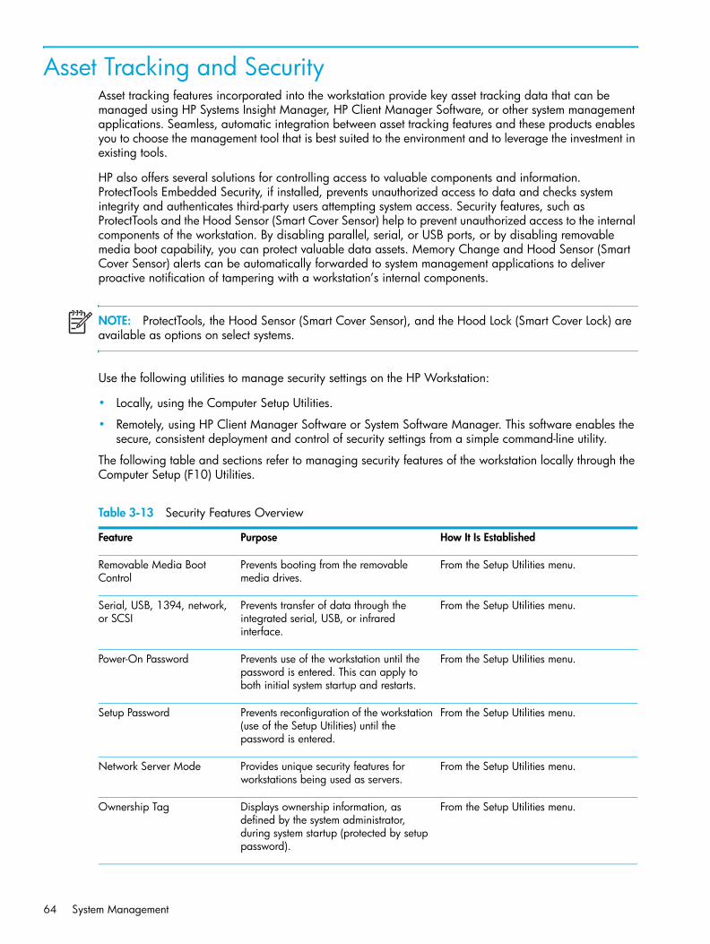
Asset Tracking and SecurityAsset tracking features incorporated into the workstation provide key asset tracking data that can be managed using HP Systems Insight Manager, HP Client Manager Software, or other system management applications. Seamless, automatic integration between asset tracking features and these products enables you to choose the management tool that is best suited to the environment and to leverage the investment in existing tools.
HP also offers several solutions for controlling access to valuable components and information. ProtectTools Embedded Security, if installed, prevents unauthorized access to data and checks system integrity and authenticates third-party users attempting system access. Security features, such as ProtectTools and the Hood Sensor (Smart Cover Sensor) help to prevent unauthorized access to the internal components of the workstation. By disabling parallel, serial, or USB ports, or by disabling removable media boot capability, you can protect valuable data assets. Memory Change and Hood Sensor (Smart Cover Sensor) alerts can be automatically forwarded to system management applications to deliver proactive notification of tampering with a workstation’s internal components.
NOTE: ProtectTools, the Hood Sensor (Smart Cover Sensor), and the Hood Lock (Smart Cover Lock) are available as options on select systems.
Use the following utilities to manage security settings on the HP Workstation:
• Locally, using the Computer Setup Utilities.
• Remotely, using HP Client Manager Software or System Software Manager. This software enables the secure, consistent deployment and control of security settings from a simple command-line utility.
The following table and sections refer to managing security features of the workstation locally through the Computer Setup (F10) Utilities.
Table 3-13 Security Features Overview
Feature Purpose How It Is Established
Removable Media Boot Control
Prevents booting from the removable media drives.
From the Setup Utilities menu.
Serial, USB, 1394, network, or SCSI
Prevents transfer of data through the integrated serial, USB, or infrared interface.
From the Setup Utilities menu.
Power-On Password Prevents use of the workstation until the password is entered. This can apply to both initial system startup and restarts.
From the Setup Utilities menu.
Setup Password Prevents reconfiguration of the workstation (use of the Setup Utilities) until the password is entered.
From the Setup Utilities menu.
Network Server Mode Provides unique security features for workstations being used as servers.
From the Setup Utilities menu.
Ownership Tag Displays ownership information, as defined by the system administrator, during system startup (protected by setup password).
From the Setup Utilities menu.
System Management64

Syste
m M
anag
emen
t
Password SecurityThe power-on password prevents unauthorized use of the workstation by requiring entry of a password to access applications or data each time the workstation is turned on or restarted. The setup password specifically prevents unauthorized access to Computer Setup, and can also be used as an override to the power-on password. That is, when prompted for the power-on password, entering the setup password instead will allow access to the workstation.
A network-wide setup password can be established to enable the system administrator to log in to all network systems to perform maintenance without having to know the power-on password.
NOTE: System Software Manager and HP Client Manager Software allow remote management of Setup Passwords and other BIOS settings in a networked environment. For more information, visit http://www.hp.com/go/easydeploy.
Establishing a Setup Password Using Computer SetupEstablishing a setup password through Computer Setup prevents reconfiguration of the workstation (use of the Computer Setup (F10) utility) until the password is entered.
To establish a setup password using workstation setup:
1. Turn on or restart the workstation.
2. As soon as the computer is turned on, press and hold the F10 until you enter Computer Setup. Press Enter to bypass the title screen, if necessary.
Cable Lock Provision Prevents entire system theft only. Install a cable lock to secure the workstation to a fixed object.
Padlock Loop Prevents access panel from being removed. This loop can also be used to secure the unit to a fixed object.
Install a security lock.
Access Panel Key Lock (Standard)
Prevents removal of the access panel and all internal components including optical and floppy drives
Lock the access panel.
Universal Chassis Clamp Lock (Optional)
The version without a cable discourages access panel removal and prevents theft of IO devices. The version with a cable additionally prevents entire system theft and allows multiple systems to be secured with a single cable.
Install a chassis clamp lock.
Hood Sensor Notifies a local or remote user when the chassis access panel has been opened.
Install an intrusion sensor.
For more information about Computer Setup, refer to “Computer Setup Menu” on page 47.
Table 3-13 Security Features Overview (continued)
Feature Purpose How It Is Established
Desktop Management 65
NOTE: If you do not press the F10 key at the appropriate time, you must restart the workstation and press and hold the F10 key again to access the utility.
If you are using a PS/2 keyboard, you might see a Keyboard Error message—disregard it.
3. Select Security > Setup Password and follow the on-screen instructions.
4. Before exiting, select File > Save Changes and Exit.
Establishing a Power-On Password Using Workstation SetupEstablishing a power-on password through Computer Setup prevents access to the workstation when power is turned on, unless the password is entered. When a power-on password is set, Computer Setup presents Password Options under the Security menu. The password options include Network Server Mode and Password Prompt on Warm Boot.
When Network Server Mode is disabled, the password must be entered each time the workstation is turned on when the key icon appears on the monitor. When Password Prompt on Warm Boot is enabled, the password must also be entered each time the workstation is rebooted. When Network Server Mode is enabled, the password prompt is not presented during POST, but any attached PS/2 keyboard will remain locked until the user enters the power-on password.
To establish a power-on password through workstation setup:
1. Turn on or restart the workstation.
2. As soon as the computer is turned on, press and hold the F10 until you enter Computer Setup. Press Enter to bypass the title screen, if necessary.
NOTE: If you do not press the F10 key at the appropriate time, you must restart the workstation and press and hold the F10 key again to access the utility.
If you are using a PS/2 keyboard, you might see a Keyboard Error message—disregard it.
3. Select Security > Power-On Password and follow the on-screen instructions.
4. Before exiting, select File > Save Changes and Exit.
Entering a Power-On PasswordTo enter a power-on password:
1. Turn on or restart the workstation.
2. When the key icon appears on the monitor, enter the current password, then press Enter.
NOTE: Type carefully. For security reasons, the characters you enter do not appear on the screen.
If you enter the password incorrectly, a broken key icon appears. Try again. After three unsuccessful tries, you must turn off the workstation, then turn it on again before you can continue.
System Management66

Syste
m M
anag
emen
t
Entering a Setup PasswordIf a setup password has been established on the workstation, you will be prompted to enter it each time you run Computer Setup.
To enter a setup password:
1. Turn on or restart the workstation.
2. As soon as the workstation is turned on, press and hold the F10 key until you enter Computer Setup. Press Enter to bypass the title screen, if necessary.
NOTE: If you do not press the F10 key at the appropriate time, you must restart the workstation and press and hold the F10 key again to access the utility.
If you are using a PS/2 keyboard, you might see a Keyboard Error message—disregard it.
3. When the key icon appears on the monitor, enter the setup password, then press Enter.
NOTE: Type carefully. For security reasons, the characters you enter do not appear on the screen.
If you enter the password incorrectly, a broken key icon appears. Try again. After three unsuccessful tries, you must turn off the workstation, then turn it on again before you can continue.
Changing a Power-On or Setup PasswordTo change a power-on or setup password:
1. Turn on or restart the workstation. To change the setup password, run Computer Setup.
2. To change the Power-On password, go to step 3.
To change the Setup password, as soon as the workstation is turned on, press and hold the F10 key until you enter Computer Setup. Press Enter to bypass the title screen, if necessary.
NOTE: If you do not press the F10 key at the appropriate time, you must restart the workstation and press and hold the F10 key again to access the utility.
If you are using a PS/2 keyboard, you might see a Keyboard Error message—disregard it.
3. When the key icon appears, type the current password, a slash (/) or alternate delimiter character, your new password, another slash (/) or alternate delimiter character, and your new password again as shown:
current password/new password/new password
NOTE: Type carefully. For security reasons, the characters you enter do not appear on the screen.
4. Press Enter.
The new password takes effect the next time you turn on the workstation.
Desktop Management 67
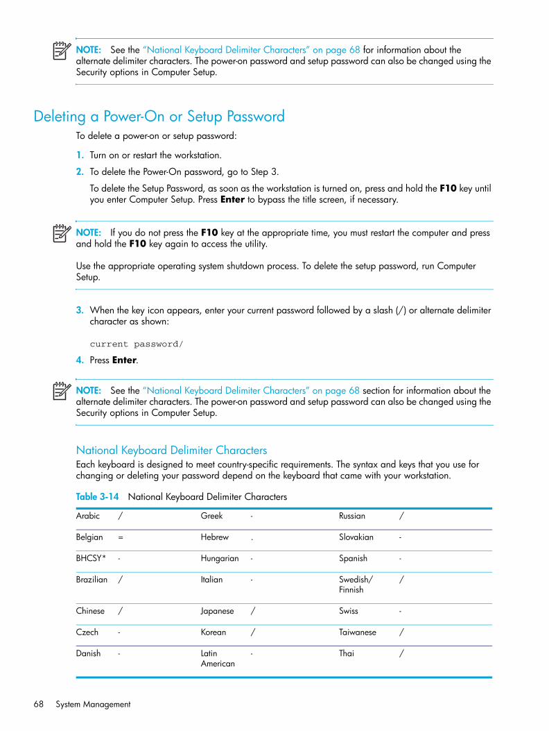
NOTE: See the “National Keyboard Delimiter Characters” on page 68 for information about the alternate delimiter characters. The power-on password and setup password can also be changed using the Security options in Computer Setup.
Deleting a Power-On or Setup PasswordTo delete a power-on or setup password:
1. Turn on or restart the workstation.
2. To delete the Power-On password, go to Step 3.
To delete the Setup Password, as soon as the workstation is turned on, press and hold the F10 key until you enter Computer Setup. Press Enter to bypass the title screen, if necessary.
NOTE: If you do not press the F10 key at the appropriate time, you must restart the computer and press and hold the F10 key again to access the utility.
Use the appropriate operating system shutdown process. To delete the setup password, run Computer Setup.
3. When the key icon appears, enter your current password followed by a slash (/) or alternate delimiter character as shown:
current password/
4. Press Enter.
NOTE: See the “National Keyboard Delimiter Characters” on page 68 section for information about the alternate delimiter characters. The power-on password and setup password can also be changed using the Security options in Computer Setup.
National Keyboard Delimiter CharactersEach keyboard is designed to meet country-specific requirements. The syntax and keys that you use for changing or deleting your password depend on the keyboard that came with your workstation.
Table 3-14 National Keyboard Delimiter Characters
Arabic / Greek - Russian /
Belgian = Hebrew . Slovakian -
BHCSY* - Hungarian - Spanish -
Brazilian / Italian - Swedish/Finnish
/
Chinese / Japanese / Swiss -
Czech - Korean / Taiwanese /
Danish - Latin American
- Thai /
System Management68

Syste
m M
anag
emen
t
Clearing PasswordsIf you forget your password, you cannot access the workstation. Refer to “Additional Password Security and Resetting CMOS” on page 203 for instructions on clearing passwords.
Hood Sensor (Smart Cover Sensor)The hood sensor is a combination of hardware and software technology that can alert you when the workstation side access panel has been removed. There are three levels of protection, as described in the following table.
Setting the hood sensor protection level To set the hood sensor protection level:
1. Turn on or restart the workstation.
2. As soon as the workstation is turned on, press and hold the F10 key until you enter Computer Setup. Press Enter to bypass the title screen, if necessary.
NOTE: If you do not press the F10 key at the appropriate time, you must restart the computer and press and hold the F10 key again to access the utility.
If you are using a PS/2 keyboard, you might see a Keyboard Error message—disregard it.
3. Select Security > Smart Cover > Cover Removal Sensor, then side access panel, and follow the on-screen instructions.
French ! Norwegian - Turkish .
French Canadian
é Polish - U.K. English /
German - Portuguese - U.S. English /
*For Bosnia-Herzegovina, Croatia, Slovenia, and Yugoslavia
Table 3-14 National Keyboard Delimiter Characters
Table 3-15 Hood Sensor Protection Levels
Level Setting Description
Level 0 Disable Hood sensor is disabled (default).
Level 1 Notify User When the workstation is restarted, the screen displays a message indicating that the workstation side access panel has been removed.
Level 2 Password When the workstation is restarted, the screen displays a message indicating that the workstation access panel has been removed. You must enter the setup password to continue.This option is only available if an administrator password is set.
NOTE: These settings can be changed using Computer Setup.
Desktop Management 69

4. Before exiting, click File > Save Changes and Exit.
Cable Lock Provision (Optional)The rear panel of the chassis can accommodate a cable lock accessory that allows the workstation to be physically secured to a work area.
Security Lock (Optional)Prevents entire system theft and discourages access panel removal.
Universal Chassis Clamp Lock (Optional)The version without a cable discourages access panel removal and prevents theft of IO devices. The version with a cable also prevents entire system theft and allows multiple systems to be secured with a single cable.
Hood Sensor (Smart Cover Sensor) This sensor is set in the Computer Setup utility. You can set this to notify a user if the access panel has been removed.
Access Panel Key LockThis lock prevents removal of the access panel and all internal components. The key is shipped on the rear of the workstation.
System Management70

Syste
m M
anag
emen
t
Fault Notification and RecoveryFault Notification and Recovery features combine innovative hardware and software technology to prevent the loss of critical data and minimize unplanned downtime.
If the workstation is connected to a network managed by HP Client Manager Software, the computer sends a fault notice to the network management application. With HP Client Manager Software, you can also remotely schedule diagnostics to automatically run on all managed PCs and create a summary report of failed tests.
Drive Protection SystemThe DPS is a diagnostic tool built into the hard drives installed in select HP workstations. DPS is designed to help diagnose problems that might result in unwarranted hard drive replacement.
When HP workstations are built, each installed hard drive is tested using DPS, and a permanent record of key information is written onto the drive. Each time DPS is run, test results are written to the hard drive. The service provider can use this information to help diagnose conditions that caused you to run the DPS software.
ECC Fault Prediction and Prefailure WarrantyWhen the workstation encounters an excessive number of error checking and correcting (ECC) memory errors, the workstation displays a Local Alert message. This message contains detailed information about the errant memory module, allowing you to take action before you experience non-correctable memory errors. The Prefailure Warranty for ECC memory modules allows you to replace these modules, free of charge, before the modules actually fail. ECC memory modules are optional on selected HP systems.
NOTE: To use this feature, you must replace the standard DIMMs with HP ECC DIMMs.
Surge-Tolerant Power SupplyAn integrated surge-tolerant power supply provides greater reliability when the workstation is hit with an unpredictable power surge. This power supply is rated to withstand a power surge of up to 2000V (Line to PE or Neutral to PE) and 1000V (Line to Line) without any data loss or system downtime.
Thermal SensorThe thermal sensor is a hardware and software feature that tracks the internal temperature of the workstation. When combined with HP Client Manager Software, this features notifies the network administrator when the normal range is exceeded.
The thermal sensor monitors the processor temperature. If the temperature does not go down, then the system eventually shuts down.
Desktop Management 71

System Management72

Rem
oval
and
Rep
lace
men
t Pr
oced
ures
4 Removal and Replacement Procedures
This chapter describes removal and replacement procedures of most internal components.
• “Service Considerations” on page 74
• “Pre-Disassembly Procedures” on page 79
• “System Board” on page 80
• “Removal and Replacement of Components” on page 82
73

Service ConsiderationsThe following sections discuss service considerations that should be reviewed and practiced before removing and replacing any system components.
WARNING! When lifting or moving the workstation, do not use the front bezel as a handle or lifting point. Lifting the workstation from the front bezel or lifting it incorrectly can cause the unit to fall and harm the user and damage the workstation. To properly and safely lift the workstation, lift it from the bottom of the unit.
• “Cautions, Warnings, and Safety Precautions” on page 74
• “Electrostatic Discharge Information” on page 75
• “Tools and Software Requirements” on page 77
• “Special Handling of Components” on page 77
Cautions, Warnings, and Safety PrecautionsFor your safety, you must review the “Important Safety Warnings” on page 10 before accessing the components of the workstation. Also, review the Safety and Regulatory Guide that came with your workstation for more information.
WARNING! Avoid Burn Injuries. Some parts inside the computer will be hot. Turn off and unplug the system, then wait approximately three to five minutes for them to cool down before opening the system access panels or touching internal components.
Removal and Replacement Procedures74

Rem
oval
and
Rep
lace
men
t Pr
oced
ures
Electrostatic Discharge InformationA sudden discharge of static electricity from your finger or other conductor can destroy static-sensitive devices or microcircuitry. Often the spark is neither felt nor heard, but damage occurs. An electronic device exposed to electrostatic discharge (ESD) might not appear to be affected at all and can work perfectly throughout a normal cycle. The device can function normally for a while, but it has been degraded in the internal layers, reducing its life expectancy.
Networks built into many integrated circuits provide some protection, but in many cases, the discharge contains enough power to alter device parameters or melt silicon junctions.
Generating StaticThe following table shows that:
• Different activities generate different amounts of static electricity.
• Static electricity increases as humidity decreases.
Preventing Electrostatic Damage to EquipmentMany electronic components are sensitive to ESD. Circuitry design and structure determine the degree of sensitivity. The following packaging and grounding precautions are necessary to prevent damage to electric components and accessories.
• Transport products in static-safe containers, such as tubes, bags, or boxes to avoid hand contact.
• Protect all electrostatic parts and assemblies with conductive or approved containers or packaging.
• Keep electrostatic sensitive parts in their containers until they arrive at static-free stations.
• Place items on a grounded surface before removing them from their container.
• When handling or touching a sensitive component or assembly, ground yourself by touching the chassis.
• Avoid contact with pins, leads, or circuitry.
• Place reusable electrostatic-sensitive parts from assemblies in protective packaging or conductive foam.
Table 4-16 Static Electricity
Relative Humidity
Event 55% 40% 10%
Walking across carpet
Walking across vinyl floorMotions of bench worker
7,500V3,000V400V
15,000V5,000V800V
35,000V12,000V6,000V
Removing bubble pack from PCBPacking PCBs in foam-lined box
7,000V5,000V
20,000V11,000V
26,500V21,000V
NOTE: 700V can degrade a product.
Service Considerations 75

Personal Grounding Methods and EquipmentUse the following equipment to prevent static electricity damage to equipment:
• Wrist straps are flexible straps with a maximum of one-megohm ± 10% resistance in the ground cords. To provide a proper ground, wear the strap against bare skin. The ground cord must be connected and fit snugly into the banana plug connector on the grounding mat or workstation.
• Heel straps, toe straps, and boot straps can be used at standing workstations and are compatible with most types of shoes or boots. On conductive floors or dissipative floor mats, use them on both feet with a maximum of one-megohm ± 10% resistance between the operator and ground.
Grounding the Work AreaTo prevent static damage at the work area:
• Cover the work surface with approved static-dissipative material. Provide a wrist strap connected to the work surface and properly grounded tools and equipment.
• Use static-dissipative mats, foot straps, or air ionizers to give added protection.
• Handle electrostatic sensitive components, parts, and assemblies by the case or PCB laminate. Handle them only at static-free work areas.
• Turn off power and input signals before inserting and removing connectors or test equipment.
• Use fixtures made of static-safe materials when fixtures must directly contact dissipative surfaces.
• Keep work area free of nonconductive materials, such as ordinary plastic assembly aids and Styrofoam.
• Use field service tools, such as cutters, screwdrivers, and vacuums, that are conductive.
Recommended Materials and EquipmentMaterials and equipment that are recommended for use in preventing static electricity include:
• Antistatic tape
• Antistatic smocks, aprons, or sleeve protectors
• Conductive bins and other assembly or soldering aids
• Conductive foam
• Conductive tabletop workstations with ground cord of one-megohm ± 10% resistance
• Static-dissipative table or floor mats with hard tie to ground
• Field service kits
• Static awareness labels
• Wrist straps and footwear straps providing one-megohm ± 10% resistance
• Material handling packages
• Conductive plastic bags
Table 4-17 Static Shielding Protection Levels
Method Voltage
Antistatic plasticCarbon-loaded plasticMetallized laminate
1,5007,50015,000
Removal and Replacement Procedures76

Rem
oval
and
Rep
lace
men
t Pr
oced
ures
• Conductive plastic tubes
• Conductive tote boxes
• Opaque shielding bags
• Transparent metallized shielding bags
• Transparent shielding tubes
Tools and Software Requirements• Torx T-15 screwdriver or flat-bladed screwdriver
• Diagnostics software
ScrewsThe screws used in the workstation are not interchangeable. They might have standard or metric threads and might be of different lengths. If an incorrect screw is used during the reassembly process, it can damage the unit. HP strongly recommends that all screws removed during disassembly be kept with the removed part, then returned to their proper locations.
Special Handling of ComponentsThe following components require special handling when servicing the workstation.
Cables and ConnectorsCables must be handled with care to avoid damage. Apply only the tension required to seat or unseat the cables during insertion or removal from the connector. Handle cables by the connector or pull strap whenever possible. In all cases, avoid bending or twisting the cables, and be sure that the cables are routed in such a way that they cannot be caught or snagged by parts being removed or replaced.
CAUTION: When servicing this workstation, be sure that cables are placed in their proper location during the reassembly process. Improper cable placement can damage the workstation.
Hard DrivesHandle hard drives as delicate, precision components, avoiding all physical shock and vibration. This applies to failed drives as well as replacement spares.
• If a drive must be mailed, place the drive in a bubble-pack mailer or other suitable protective packaging and label the package “Fragile: Handle With Care.”
• Do not remove hard drives from the shipping package for storage. Keep hard drives in their protective packaging until they are actually mounted in the workstation.
• Avoid dropping drives from any height onto any surface.
• If you are inserting or removing a hard drive, turn off the workstation. Do not remove a hard drive while the workstation is on or in Standby mode.
• Before handling a drive, be sure that you are discharged of static electricity. While handling a drive, avoid touching the connector. For more information about preventing electrostatic damage, refer to “Electrostatic Discharge Information” on page 75.
Service Considerations 77

• Do not use excessive force when inserting a drive.
• Avoid exposing a hard drive to liquids, temperature extremes, or products that have magnetic fields such as monitors or speakers.
Lithium Coin Cell BatteryThe battery that comes with the workstation provides power to the real-time clock and has a minimum lifetime of about three years.
For instructions on battery removal and replacement, see the “Battery” section on page 105.
WARNING! This workstation contains a lithium battery. There is a risk of fire and chemical burn if the battery is handled improperly. Do not disassemble, crush, puncture, short external contacts, dispose in water or fire, or expose it to temperatures higher than 140 F (60 C).
CAUTION: Batteries, battery packs, and accumulators should not be disposed of together with the general household waste.Batterij niet
weggooien,maar inleveren
als KCA.
Removal and Replacement Procedures78

Rem
oval
and
Rep
lace
men
t Pr
oced
ures
Pre-Disassembly ProceduresBefore servicing the workstation:
1. Close any open software applications.
2. Remove any diskette or compact disc from the workstation.
3. Exit the operating system.
4. Turn off the workstation and any peripheral devices that are connected to it.
5. Remove/disengage any security devices that prohibit opening the workstation.
CAUTION: Turn off the workstation before disconnecting any cables.
CAUTION: The cooling fan is off only when the workstation is turned off or the power cable has been disconnected. The cooling fan is always on when the workstation is in the “On,” “Standby,” or “Suspend” modes. You must disconnect the power cord from the power source before opening the workstation to prevent system board or component damage.
6. Disconnect the power cord from the electrical outlet and then from the workstation.
7. Disconnect all peripheral device cables from the workstation.
Pre-Disassembly Procedures 79

System Board This section provides additional information about the system board.
• “System Board Components” on page 80
• “System Board Architecture” on page 81
System Board ComponentsThe following illustration shows the system board connectors and sockets on the HP xw9300 Workstation.
Table 4-18 System Board Components
1 Memory module pairs 13 Hard disk activity LED 25 CD audio
2 Processor 0 fan 14 Internal SCSI (Channel 1) 26 Battery
3 Processor 0 15 Password jumper 27 PCI-X 133
4 CPU0/1 power connector 16 Serial ATA ports 2 (left) and 3 (right)
28 PCI-X 100
5 Main power 17 Front panel USB 29 PCI Express x16
6 Clear CMOS button 18 PCI-X 133 slot speed 30 Rear chassis fan
7 Boot block jumper 19 PCI-X 100 slot speed 31 PCI
8 External SCSI (Channel 0) 20 Front control panel 32 PCI Express x16
9 Diskette drive 21 Front IEEE 1394 33 Processor 1
10 Serial ATA ports 0 (top) and 1 (bottom)
22 Trusted Platform Module 34 Processor 1 fan
11 Primary IDE* 23 Front panel
12 Front chassis fan 24 Auxiliary audio
*The Primary IDE connector is only used for optical drives.
Removal and Replacement Procedures80

Rem
oval
and
Rep
lace
men
t Pr
oced
ures
System Board ArchitectureThe following illustration shows the HP xw9300 Workstation block diagram.
System Board 81

Removal and Replacement of ComponentsThis section discusses the procedures necessary to remove and install various hardware components on your workstation. Review the safety and precautions and “Service Considerations” on page 74, as well as the Safety and Regulatory Guide, before servicing or upgrading your system.
1. Read all safety information and precautions.
2. Locate and clear a suitable work area.
3. Shut down the system and remove power from the unit.
4. Gather your tools.
5. Service your unit.
6. Restore power to your unit.
Removal and Replacement Procedures82

Rem
oval
and
Rep
lace
men
t Pr
oced
ures
Disassembly OrderUse the following table to determine the sequence in which to remove the major components.
Pre-Disassembly (page 79)
Locks (page 84)
Access Panel (page 86)
Hood sensor (page 88)
Front Bezel (page 87)
Front Panel I/O Device Assembly (page 89)
Power Button and Front Speaker (page 90)
Optical Drive (page 107)
Diskette Drive (page 109)
Bezel Blanks (page 87)
Power Supply (page 91)
Memory Duct (page 92)
System Fan (page 93)
Memory (page 94)
Front Fan (page 103)
Battery (page 105)
Hard Drive (page 111)
CPU Heatsink (page 116)
Processor (page 127)
PCI Card Support (page 98)
PCI or PCI Express card (page 100)
System Board (page 129)
Removal and Replacement of Components 83

Security Lock (Optional)If a security lock is installed, remove it before servicing the unit. To remove the security lock, unlock it and slide it out of the padlock loop as shown in the following image.
Cable Lock (Optional)If a cable lock is installed, remove it before servicing the unit. To remove the cable lock, unlock it and pull it out of the cable lock slot as shown in the following image.
Removal and Replacement Procedures84

Rem
oval
and
Rep
lace
men
t Pr
oced
ures
Universal Chassis Clamp LockIf a universal chassis clamp lock is installed, remove it before servicing the unit.
To remove the lock:
1. Unlock the device and remove the locking mechanism.
2. Remove the screw attaching the lock to the chassis.
Removal and Replacement of Components 85

Access PanelBefore accessing the internal components of the workstation, the access panel must be removed.
To remove the access panel:
WARNING! Before removing the workstation access panel, be sure that the workstation is turned off and that the power cord is disconnected from the electrical outlet.
1. Disconnect power from the system (page 79) and lay the workstation on its side as shown.
2. If necessary, unlock the access panel (page 84). The keys are on the rear panel.
3. Pull up 1 on the handle and lift off 2 the cover.
To replace the access panel, slide the cover back on until it snaps into place.
Removal and Replacement Procedures86

Rem
oval
and
Rep
lace
men
t Pr
oced
ures
Front BezelTo remove the front bezel:
1. Disconnect power from the system (page 79) and open the access panel (page 86).
2. Lift up on the three tabs 1 located on the front bezel.
3. Rotate the front bezel away 2 from the chassis and remove the bezel.
To replace the front bezel, reverse the previous steps.
Bezel BlanksTo remove the bezel blank:
1. Disconnect power from the system (page 79), open the access panel (page 86), and remove the front bezel (page 87).
2. Remove the bezel blank by pushing in on the tabs 1 and pushing the bezel blank out 2.
To replace the bezel blank, push in on the tabs and push the bezel blank into the bezel.
Removal and Replacement of Components 87

Hood SensorTo remove the hood sensor:
1. Disconnect power from the system (page 79) and remove the access panel (page 86).
2. Unlatch the plastic snap that secures the cables inside the chassis.
3. Disconnect the white 1x3 hood sensor connector from the in-line connector attached to the front panel harness.
4. Slide the hood sensor forward, push the hood sensor down, and remove it from the chassis.
CAUTION: Be careful when sliding the hood sensor forward. The hood sensor bracket and the chassis contain sharp edges that present a safety hazard.
To replace the hood sensor, reverse the previous steps.
Removal and Replacement Procedures88

Rem
oval
and
Rep
lace
men
t Pr
oced
ures
Front Panel I/O Device AssemblyTo remove the front panel I/O device assembly:
1. Disconnect power from the system (page 79), remove the access panel (page 86), and remove the front bezel (page 87).
2. Unlatch the plastic snap that secures the cables inside the chassis and disconnect the front panel I/O device assembly cables from the system board.
3. Remove the screws that hold the front panel I/O device assembly and bracket to the chassis 1 and remove the screws that hold the front panel I/O device assembly to the bracket 2.
4. Pull the front panel I/O device assembly out about two inches away from the chassis.
5. Separate the bracket away from the front panel I/O device assembly.
WARNING! The next step requires the removal of cables through the chassis. Some edges on the chassis might be sharp. Be careful when removing these cables.
6. Slide the front panel cables through the chassis and out the front of the unit.
To replace the front panel I/O device assembly, reverse the previous steps.
Removal and Replacement of Components 89

Power Button Assembly and System SpeakerThe power button and the system speaker are part of the same assembly.
To remove the power button:
1. Disconnect power from the system (page 79), remove the access panel (page 86), remove the front bezel (page 87), and remove the front panel I/O device assembly (page 89).
2. Disconnect the power button assembly cable from the system board.
3. Disconnect the speaker wire and the hood sensor from the in-line connectors on the power button assembly cable.
4. Remove the screw 1 that secures the power button assembly to the chassis.
5. Dislodge the metal clip from the chassis by rocking the power button back and forth. Then slide the power button assembly 2 out from the front of the chassis.
To remove the speaker:
1. Disconnect the speaker cable from the in-line front panel I/O device assembly cable, if you have not already done so.
2. Slide the speaker away from the three flanges and remove it from the chassis.
Removal and Replacement Procedures90

Rem
oval
and
Rep
lace
men
t Pr
oced
ures
Power SupplyTo remove the power supply:
1. Disconnect power from the system (page 79) and remove the access panel (page 86).
2. Disconnect the power supply from the system board.
3. Disconnect the power supply cables from the optical drives, diskette drive, hard drives, and graphics cards (select models only).
4. Remove the four screws 1 from the back panel.
5. Slide the power supply toward the front and lift up 2 to remove it from the chassis.
To replace the power supply, reverse the previous steps.
Removal and Replacement of Components 91

Memory DuctTo remove the memory duct:
1. Disconnect power from the system (page 79) and remove the access panel (page 86).
2. Press in to unlatch the plastic clip 1 and pull the duct away from the fan 2.
Removal and Replacement Procedures92

Rem
oval
and
Rep
lace
men
t Pr
oced
ures
System FanTo remove the system fan:
1. Disconnect power from the system (page 79), remove the access panel (page 86), and remove the memory duct (page 92).
2. Disconnect the fan plug 1 from the system board.
3. Press in on the ribbed portion of the fan housing 2, rotate the fan housing down 3, and lift it out of the chassis.
To replace the system fan, reverse the previous steps.
CAUTION: When replacing the system fan, be sure that the fan is situated so that the airflow direction arrow is pointing toward the back of the chassis. To see the airflow direction arrow, you must remove the fan from the fan holder.
Removal and Replacement of Components 93

Memory
Memory Module Features • Contains 8 memory slots for DIMMS
• Supports 512MB, 1GB, and 2GB pairs
• Supports 1GB minimum configuration (2 x 512 DIMM)
• Supports 16GB maximum configuration (8GB maximum on Windows and 16GB maximum on Linux)
• Supports dual-channel DIMMs
Memory Module Requirements• Use only industry-standard, registered, PC-3200 DIMMs
• Match DIMM pairs by size and type
• No support for unbuffered memory
To remove a memory module:
1. Disconnect power from the system (page 79), remove the access panel (page 86), and remove the memory duct (page 92).
CAUTION: To ensure that memory modules are not damaged during removal or installation, power off the workstation and unplug the power cord from the AC power outlet. Wait until the LED on the back of the power supply turns off before removing memory. If you do not unplug the power cord while installing memory, your memory modules might be damaged and the system will not recognize the memory changes.
2. Gently push outwards on the socket levers 1.
3. Lift the DIMM 2 straight up and remove it from the unit.
Removal and Replacement Procedures94

Rem
oval
and
Rep
lace
men
t Pr
oced
ures
To install a memory module:
CAUTION: HP only ships DIMMs that are electrically and thermally compatible with this product. Because third-party DIMMs might not be electrically or thermally compatible, they are not supported by HP.
NOTE: DIMMs and their sockets are keyed for proper installation. Be sure these guides line up when installing a DIMM.
Loading Order for Single Processor ConfigurationsUse the following image as a guide for installing memory in single processor configurations only. You must install memory modules in valid configurations:
• Install the first DIMM pair in socket set 1 (blue sockets)
• Install the second DIMM pair in socket set 3 (black sockets)
Loading Order for Dual Processor ConfigurationsUse the following image as a guide for installing memory in dual processor configurations only. You must load memory modules in valid configurations:
• Install the first DIMM pair in socket set 1 (blue sockets)
• Install the second DIMM pair in socket set 2 (blue sockets)
• Install the next two DIMM pairs in socket sets 3 and 4 (black sockets)
1. Disconnect power from the system (page 79), remove the access panel (page 86), and remove the memory duct (page 92).
2. Gently push outwards on the socket levers.
Removal and Replacement of Components 95

3. Lower the DIMM straight down and be sure the socket levers secure the module into place.
Removal and Replacement Procedures96

Rem
oval
and
Rep
lace
men
t Pr
oced
ures
Peripheral Component Interconnect (PCI) SlotsThe section contains information on the following topics:
• “PCI Slot Types” on page 97
• “PCI Card Support” on page 98
• “PCI Express” on page 99
• “PCI or PCI-X” on page 101
PCI Slot Types
Table 4-19 PCI Slot Types
Slot Type Slot Type
1 PCI Express x16 4 PCI-X 100**
2 PCI 5 PCI-X 100**
3 PCI Express x16* 6 PCI-X 133***
*PCI Express slot is only active in the dual-processor configuration (item 3 only). This slot cannot be used in a single-processor configuration.**To limit operation to a maximum of 66MHz, install the jumper on both pins of J92 (see “PCI-X 100 slot speed” on page 80).***To limit operation to a maximum of 100MHz, install the jumper on both pins of J96 (see “PCI-X 133 slot speed” on page 80).
Removal and Replacement of Components 97

PCI Card SupportFor added protection, some cards have PCI holders installed to prevent movement during shipping.
To remove the card support:
1. Disconnect power from the system (page 79) and remove the access panel (page 86).
2. For short or tall PCI cards, lift up on the holder arm 1 with one hand and press in on the sides 2 of the holder and rotate it 3 out of the chassis.
To install card support:
1. Disconnect power from the system (page 79) and remove the access panel (page 86).
2. For short or tall PCI cards, attach the lips of the support arm 1 under the slots on the rear of the chassis, then rotate the card support down until the black part of the arm 2 supports the card.
Removal and Replacement Procedures98

Rem
oval
and
Rep
lace
men
t Pr
oced
ures
PCI ExpressPCI Express, a new hardware interconnect standard (for example, I/O slots), is a point-to-point architecture and uses a serial data transmission protocol. A single PCI Express lane consists of four wires and is capable of transmitting 250MB in a single direction or 500MB in both directions simultaneously. This bandwidth is not affected by what is happening on other PCI Express buses or legacy PCI/PCI-X buses (provided that total bandwidth can be handled by the CPU and the memory subsystem). The transmission protocol is similar to what is used for a LAN connection and contains error correction and detection, packet addressing, and other network features.
PCI Express improves system attributes. PCI Express enables a low-power, scalable, high-bandwidth communication path with a small number of connections (wires) compared to traditional parallel interfaces (for example, PCI).
The PCI Express I/O slots can support other PCI Express cards with lesser bus bandwidth than what is physically defined for the slot. Use the following table to determine compatibility.
NOTE: The HP xw9300 Workstation contains two PCI Express x16 slots. PCI Express slot three (see illustration “PCI Slot Types” on page 97 is only active in the dual-processor configuration. This slot cannot be used in a single-processor configuration.
Table 4-20 PCI Express Compatibility Matrix for HP xw9300 Workstation
PCI Express x16 Slot
PCI Express x1 Card Y
PCI Express x4 Card Y
PCI Express x8 Card Y
PCI Express x16 Card Y
Removal and Replacement of Components 99

To remove a PCI Express card:
1. Disconnect power from the system (page 79), remove the access panel (page 86) and remove the PCI card support (page 98), if installed.
2. Lift the PCI levers 1 by first pressing down and then up.
3. Remove the power supply cable 2, if installed, and press in on the “hockey stick” lever 3 while lifting the card 4 out of the chassis. Store the card in an anti-static bag.
4. Install a PCI slot cover and close the PCI levers. If the PCI levers do not close, be sure all cards are properly seated and then try again.
To install a PCI Express card:
1. Disconnect power from the system (page 79), remove the access panel (page 86) and remove the PCI card support (page 98), if installed.
2. Lift the PCI levers 1 by first pressing down and then up.
3. Remove the PCI slot cover 2.
4. Lower the PCI Express 3 card into the chassis. Verify that the keyed components of the card align with the socket.
5. If required, plug in the power supply cable 4.
6. Close the PCI levers 5. If the PCI levers do not close, be sure all cards are properly seated.
Removal and Replacement Procedures100

Rem
oval
and
Rep
lace
men
t Pr
oced
ures
PCI or PCI-X
NOTE: The following illustration shows a PCI card being removed from a PCI slot. A PCI-X card is removed from a PCI-X slot.
To remove a PCI or PCI-X card:
1. Disconnect power from the system (page 79), remove the access panel (page 86) and remove the PCI card support (page 98), if installed.
2. Lift the PCI levers 1 by first pressing down and then up.
3. Lift the PCI card 2 out of the chassis. Store the card in an anti-static bag.
4. Install a PCI slot cover and close the PCI levers. If the PCI levers do not close, be sure all cards are properly seated and then try again.
Removal and Replacement of Components 101
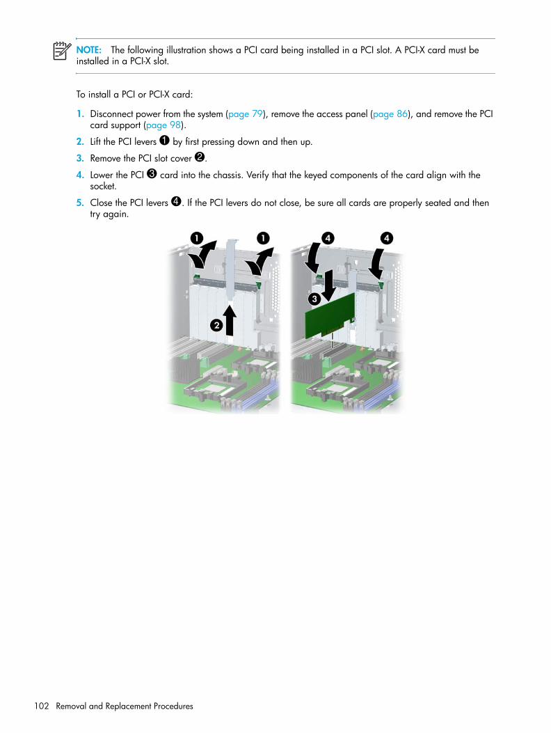
NOTE: The following illustration shows a PCI card being installed in a PCI slot. A PCI-X card must be installed in a PCI-X slot.
To install a PCI or PCI-X card:
1. Disconnect power from the system (page 79), remove the access panel (page 86), and remove the PCI card support (page 98).
2. Lift the PCI levers 1 by first pressing down and then up.
3. Remove the PCI slot cover 2.
4. Lower the PCI 3 card into the chassis. Verify that the keyed components of the card align with the socket.
5. Close the PCI levers 4. If the PCI levers do not close, be sure all cards are properly seated and then try again.
Removal and Replacement Procedures102

Rem
oval
and
Rep
lace
men
t Pr
oced
ures
Front Fan To remove the front fan:
1. Disconnect power from the system (page 79) and remove the access panel (page 86).
2. Disconnect the header 1 from the system board and thread it out of the card guide.
3. Unsnap the fan housing from the chassis 2 and lift it out of the workstation.
4. Remove the fan from the fan housing by applying outward pressure on the fan housing while pushing the fan out of the housing.
Removal and Replacement of Components 103

To replace the front fan:
1. Attach the fan to the fan housing as shown in the previous illustration.
2. Lower the fan holder 1 into the chassis and snap it into place. Be sure that the airflow direction arrow on the side of the fan faces the rear of the chassis.
3. Plug the header 2 into the red connector on the system board.
Removal and Replacement Procedures104
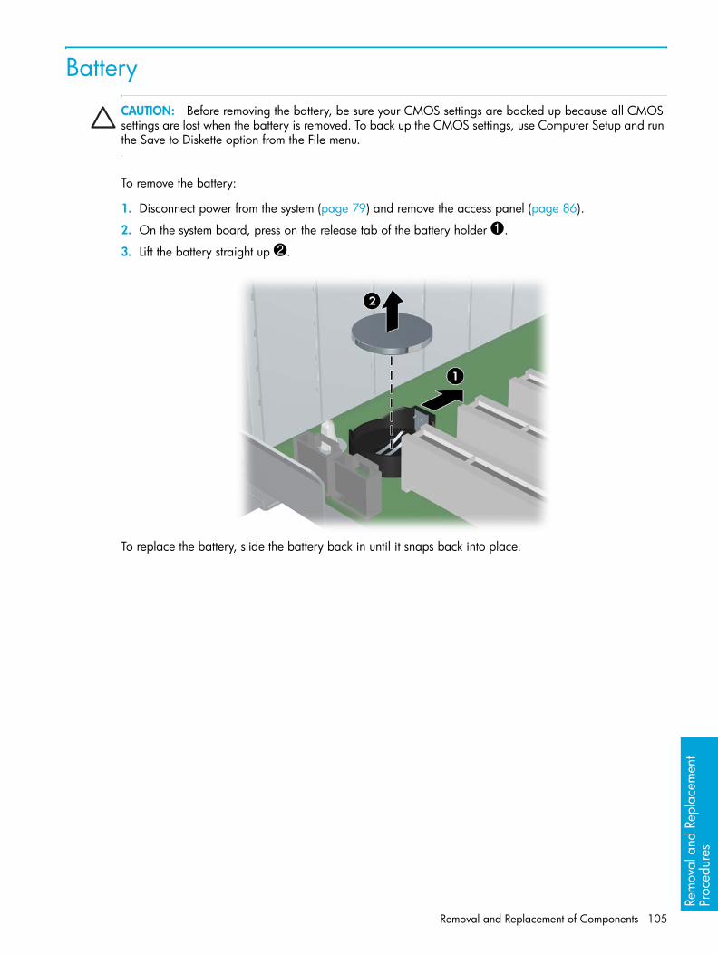
Rem
oval
and
Rep
lace
men
t Pr
oced
ures
BatteryCAUTION: Before removing the battery, be sure your CMOS settings are backed up because all CMOS settings are lost when the battery is removed. To back up the CMOS settings, use Computer Setup and run the Save to Diskette option from the File menu.
To remove the battery:
1. Disconnect power from the system (page 79) and remove the access panel (page 86).
2. On the system board, press on the release tab of the battery holder 1.
3. Lift the battery straight up 2.
To replace the battery, slide the battery back in until it snaps back into place.
Removal and Replacement of Components 105

Power Connections to DrivesFor help in identifying power cables, refer to the following information. Route or tie cables so that there is no possible way for them to interfere with the CPU heatsink fans.
Removal and Replacement Procedures106
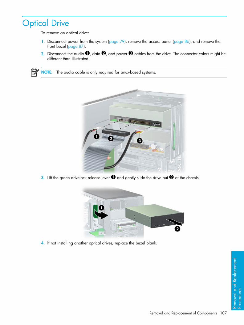
Rem
oval
and
Rep
lace
men
t Pr
oced
ures
Optical Drive To remove an optical drive:
1. Disconnect power from the system (page 79), remove the access panel (page 86), and remove the front bezel (page 87).
2. Disconnect the audio 1, data 2, and power 3 cables from the drive. The connector colors might be different than illustrated.
NOTE: The audio cable is only required for Linux-based systems.
3. Lift the green drivelock release lever 1 and gently slide the drive out 2 of the chassis.
4. If not installing another optical drives, replace the bezel blank.
Removal and Replacement of Components 107

To replace an optical drive:
1. Slide the optical drive into the bay until it stops. Lift the green drivelock release lever and push the drive in a few more inches, then release the lever and slide the drive completely into the bay until the drive is secured.
CAUTION: Ensure that the optical drive is secure. Failure to do so can cause damage to the drive when moving the workstation.
2. Connect the power, drive, and audio (if required) cables to the drive and workstation.
NOTE: The audio cable is only required for Linux-based systems.
Removal and Replacement Procedures108

Rem
oval
and
Rep
lace
men
t Pr
oced
ures
Diskette DriveTo remove a diskette drive:
1. Disconnect power from the system (page 79), remove the access panel (page 86), and remove the front bezel (page 87).
2. Disconnect the data 1 and power 2 cables from the back of the diskette drive.
3. While lifting the green drivelock release tab 1, slide the drive forward 2 out of the chassis.
4. Remove the diskette drive by removing the two M3 screws 1 in the rearmost holes and sliding the diskette drive 2 from the bracket.
Removal and Replacement of Components 109

To replace a diskette drive:
1. Slide the diskette drive into the bracket and secure with two M3 screws in the rearmost holes.
2. Slide the optical drive into the bay until it stops. Lift the green drivelock release lever and push the drive in a few more inches, then release the lever and slide the drive completely into the bay until the drive is secured.
3. Connect the data cable to the diskette drive 1 and to the system board 2. Route the data cable between the system board and the hard drive cage. Your cable might look different than the one shown.
CAUTION: The cable must stay between the system board and the hard drive cage. It might be necessary to push the cable down so that it catches on the system board. This routing method is important because you do not want to interfere with the CPU heatsink fans or block airflow.
4. Connect the power cable to the diskette drive.
Removal and Replacement Procedures110

Rem
oval
and
Rep
lace
men
t Pr
oced
ures
Hard Disk DriveFor more information on SATA hard drives and the SATA RAID configuration, see “SATA Devices” on page 177.
To remove a hard drive:
1. Disconnect power from the system (page 79) and remove the access panel (page 86).
2. Disconnect the data 1 and power 2 cables from the hard drive.
3. Squeeze the green drivelock release tabs 3 and slide the hard drive out 4 of the chassis.
Installing a SCSI Hard DriveFor more information on SCSI hard drives, see “SCSI Devices” on page 171.
Before installing a SCSI hard drive on your system, you must give the hard drive a unique SCSI ID.
All SCSI controllers require a unique SCSI ID (0–15) for each SCSI device that is installed. The reserved and available SCSI ID numbers are displayed in the following list:
• 0 is reserved for the primary hard drive (not reserved for the primary hard drive on Linux).
• 7 is reserved for the SCSI controller.
• 1 through 6 and 8 through 15 are available for all other SCSI devices.
When 0 is used for the primary hard drive, set the second hard drive to 1, the third to 2, and so on.
To set the SCSI ID on a drive, see the instructions on top/back of the hard drive for the correct jumper settings. The drive probably displays a diagram of the jumper block. This diagram shows you which blocks to cover with your jumper to get the desired ID.
For example, if the drive must be set to 3, the drive might show that the 4 ID bits are at the far left of the connector (ID0, ID1, ID2, and ID3), then using the jumpers provided, cover the pins to set the SCSI ID.
After you have given the hard drive a unique SCSI ID, you can install the hard drive into your system.
1. Disconnect power from the system (page 79) and remove the access panel (page 86).
2. Select a drive bay in which to install the drive.
3. Squeeze the green tabs of the rail assembly and slide the rails out of the empty bay.
Removal and Replacement of Components 111

4. Attach the rails to the hard drive by first inserting the hard drive rail assembly pins into one side of the hard drive screw holes. Next, gently flex open the opposite side of the hard drive rail assembly and insert the remaining pins into the holes in the hard drive. If installing the hard drive into bay 5, skip this step.
5. Push the drive into the selected bay until it snaps into place. Then attach the power and SCSI cable to the drive.
NOTE: If installing a hard drive into bay 5, lay the workstation on its side and remove the three drive screws that are located near bay 5. Insert the drive into bay 5 and align the holes in the bottom of the hard drive with the screw holes at the base of the chassis. Insert the screws through the base and tighten the hard drive to the chassis.
Removal and Replacement Procedures112

Rem
oval
and
Rep
lace
men
t Pr
oced
ures
6. Connect the data cable to the internal SCSI connector on the system board.
Removal and Replacement of Components 113

Installing an External SCSI Hard DriveYou can add an external SCSI connector to the on-board SCSI controller.
To install the external connector:
1. Disconnect power from the system (page 79), remove the access panel (page 86), and remove the PCI card support (page 98), if installed.
2. Disconnect the optical drive cable and the diskette drive cable, if installed, from the system board.
3. Plug the data cable into the external SCSI port on the system board and route the cable under the PCI card guide as shown in the following illustration.
4. Reconnect the optical drive cable and the diskette drive cable, if installed, to the system board.
5. Lift the PCI levers 1 by first pressing down and then up.
6. Remove the PCI slot cover 2 from closest to the system fan.
7. Lower the other end of the data cable 3 into the chassis.
8. Close the PCI levers 4. If the PCI levers do not close, be sure all cards are properly seated.
Removal and Replacement Procedures114

Rem
oval
and
Rep
lace
men
t Pr
oced
ures
Installing a SATA Hard DriveFor more information on SATA hard drives and the SATA RAID configuration, see “SATA Devices” on page 177.
To install one to four SATA drives:
1. Disconnect power from the system (page 79) and remove the access panel (page 86).
2. Select a drive bay in which to install the drive. Squeeze the green tabs and slide the rails out of the empty bay.
3. Attach the rails to the hard drive by aligning the notches with the holes and squeezing it into place (see image on page 112).
4. Push the drive into the selected bay until it snaps into place (see page 112 for image of SCSI drive being pushed into drive bay).
5. Connect the data cable to the serial ATA ports:
• Connect SATA0 to the top port on item 1.
• Connect SATA1 to the bottom port on item 1.
• Connect SATA2 to the left port on item 2.
• Connect SATA3 to the right port on item 2.
6. Connect the power cable to the drives.
To install more than four SATA hard drives:
NOTE: If installing more than four SATA hard drives, you must install a SATA controller card and use hard drive bay five.
1. Lay the workstation on its side with the system board facing up.
2. Insert the drive into bay 5 and align the holes in the bottom of the hard drive with the screw holes at the base of the chassis.
3. Insert the screws through the base and tighten the hard drive to the chassis.
4. Attach the power and data cable to the drive.
5. Insert a SATA controller card into an available PCI expansion slot (page 101).
6. Connect the other end of the SATA cable to the SATA controller card.
7. Connect one end of the hard drive LED cable to the SATA card and the other end to the system board (see correct location on page 80).
Removal and Replacement of Components 115

CPU HeatsinkThe HP Workstation ships with more than one type of heatsink. Use the directions that best match your heatsink.
CPU Heatsink ATo remove the CPU heatsink:
1. Turn on the workstation and enter Computer Setup (F10) (page 44). Let the workstation run in this mode for five minutes.
This action warms the thermal interface material between the CPU heatsink and processor so that the thermal bond loosens and can more easily be broken.
CAUTION: If you remove the CPU heatsink while the thermal pad is cold, you could lift the processor out of the socket, even if the socket is closed. This could damage the processor and the processor socket.
NOTE: Windows in idle state does not provide sufficient heat to warm the compound.
2. After warming the thermal interface, quickly shut down the system, disconnect power from the system (page 79) and remove the access panel (page 86).
3. Remove the CPU airflow duct by lifting up on the tabs 1 and rotating the duct away 2 from the CPU heatsinks.
NOTE: If a memory duct is installed, remove it first.
NOTE: The CPU airflow duct is only required when two processors are installed.
Removal and Replacement Procedures116
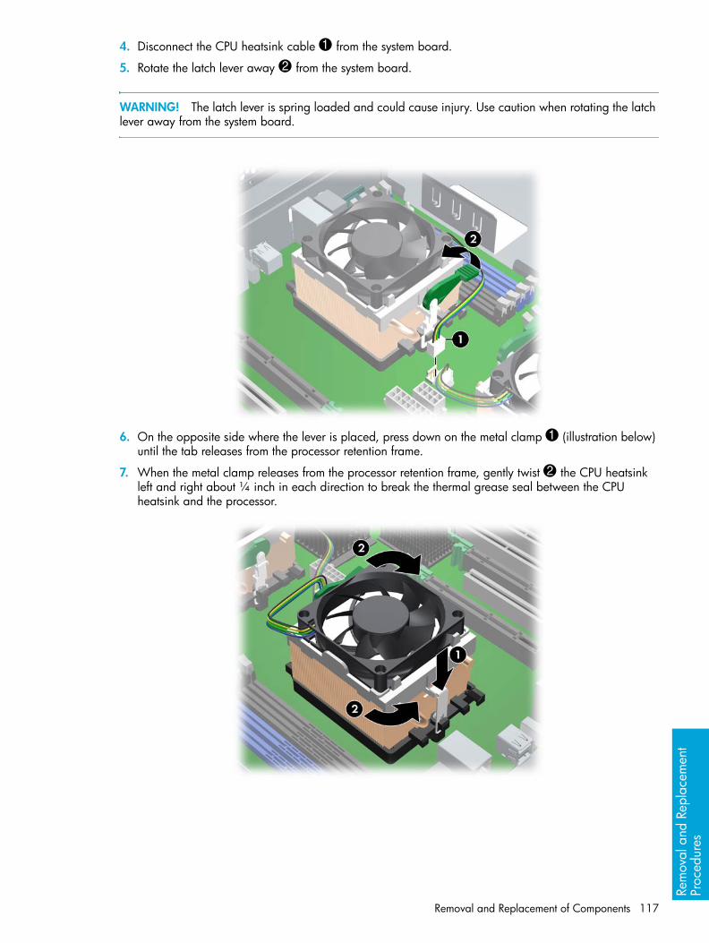
Rem
oval
and
Rep
lace
men
t Pr
oced
ures
4. Disconnect the CPU heatsink cable 1 from the system board.
5. Rotate the latch lever away 2 from the system board.
WARNING! The latch lever is spring loaded and could cause injury. Use caution when rotating the latch lever away from the system board.
6. On the opposite side where the lever is placed, press down on the metal clamp 1 (illustration below) until the tab releases from the processor retention frame.
7. When the metal clamp releases from the processor retention frame, gently twist 2 the CPU heatsink left and right about ¼ inch in each direction to break the thermal grease seal between the CPU heatsink and the processor.
Removal and Replacement of Components 117

8. Rotate the CPU heatsink away 1 from the system board by lifting the side where you released the metal clamp and rotating the entire CPU heatsink assembly away from the processor retention frame.
9. When you have rotated the CPU heatsink assembly about 45 degrees, free the metal clamp 2 that is under the black tension lever then lift the CPU heatsink up and away from the system board.
10.Use alcohol and a soft cloth to clean all of the thermal interface material residue from the CPU heatsink and processor.
CAUTION: Allow the alcohol on the processor and CPU heatsink to dry completely.
To replace the CPU heatsink:
1. Disconnect power from the system (page 79), remove the access panel (page 86), and remove the CPU heatsink (page 116).
2. Use alcohol and a soft cloth to clean all of the thermal interface material residue from the CPU heatsink and processor. If using a new CPU heatsink, do not clean the fresh thermal interface material.
CAUTION: Allow the alcohol on the processor and CPU heatsink to dry completely.
3. Check for proper processor seating in the socket by carefully trying to lift the processor out of the socket with your fingers. A properly seated processor does not lift out of the socket.
4. Apply thermal grease to center of the processor. If using a new CPU heatsink, remove and discard the thermal grease protective liner from the bottom of the new CPU heatsink. Also in this case, you do not have to apply thermal grease to the processor.
NOTE: Do not touch the exposed thermal grease when handling the CPU heatsink.
Removal and Replacement Procedures118

Rem
oval
and
Rep
lace
men
t Pr
oced
ures
5. Hook the metal latch over the plastic frame 1 and rotate the CPU heatsink down 2.
6. On the opposite side, clip the metal latch over the plastic frame.
Removal and Replacement of Components 119

7. Rotate the latch lever down 1. It will be almost parallel with the sytem board.
8. Connect the CPU heatsink cable to the white processor fan connector 2.
CAUTION: If the CPU heatsink cable does not reach the fan connector, you have installed the CPU heatsink backwards.
9. Lower the CPU airflow duct over the CPU heatsinks until it snaps into place.
NOTE: The CPU airflow duct is only required when two processors are installed.
NOTE: If a memory duct was installed previously, install it after installing the CPU airflow duct.
Removal and Replacement Procedures120

Rem
oval
and
Rep
lace
men
t Pr
oced
ures
CPU Heatsink BTo remove the CPU heatsink:
1. Turn on the workstation and enter Computer Setup (F10) (page 44). Let the workstation run in this mode for five minutes.
This action warms the thermal interface material between the CPU heatsink and processor so that the thermal bond loosens and can more easily be broken.
CAUTION: If you remove the CPU heatsink while the thermal pad is cold, you could lift the processor out of the socket, even if the socket is closed. This could damage the processor and the processor socket.
NOTE: Windows in idle state does not provide sufficient heat to warm the compound.
2. After warming the thermal interface, quickly shut down the system, disconnect power from the system (page 79) and remove the access panel (page 86).
3. Remove the CPU airflow duct by lifting up on the tabs 1 and rotating the duct away 2 from the CPU heatsinks.
NOTE: The CPU airflow duct is only required when two processors are installed.
Removal and Replacement of Components 121
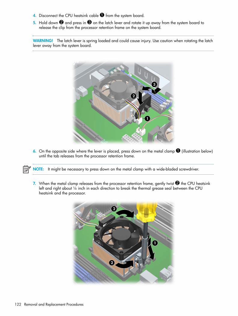
4. Disconnect the CPU heatsink cable 1 from the system board.
5. Hold down 2 and press in 3 on the latch lever and rotate it up away from the system board to release the clip from the processor retention frame on the system board.
WARNING! The latch lever is spring loaded and could cause injury. Use caution when rotating the latch lever away from the system board.
6. On the opposite side where the lever is placed, press down on the metal clamp 1 (illustration below) until the tab releases from the processor retention frame.
NOTE: It might be necessary to press down on the metal clamp with a wide-bladed screwdriver.
7. When the metal clamp releases from the processor retention frame, gently twist 2 the CPU heatsink left and right about ¼ inch in each direction to break the thermal grease seal between the CPU heatsink and the processor.
Removal and Replacement Procedures122
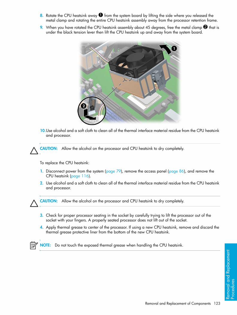
Rem
oval
and
Rep
lace
men
t Pr
oced
ures
8. Rotate the CPU heatsink away 1 from the system board by lifting the side where you released the metal clamp and rotating the entire CPU heatsink assembly away from the processor retention frame.
9. When you have rotated the CPU heatsink assembly about 45 degrees, free the metal clamp 2 that is under the black tension lever then lift the CPU heatsink up and away from the system board.
10.Use alcohol and a soft cloth to clean all of the thermal interface material residue from the CPU heatsink and processor.
CAUTION: Allow the alcohol on the processor and CPU heatsink to dry completely.
To replace the CPU heatsink:
1. Disconnect power from the system (page 79), remove the access panel (page 86), and remove the CPU heatsink (page 116).
2. Use alcohol and a soft cloth to clean all of the thermal interface material residue from the CPU heatsink and processor.
CAUTION: Allow the alcohol on the processor and CPU heatsink to dry completely.
3. Check for proper processor seating in the socket by carefully trying to lift the processor out of the socket with your fingers. A properly seated processor does not lift out of the socket.
4. Apply thermal grease to center of the processor. If using a new CPU heatsink, remove and discard the thermal grease protective liner from the bottom of the new CPU heatsink.
NOTE: Do not touch the exposed thermal grease when handling the CPU heatsink.
Removal and Replacement of Components 123
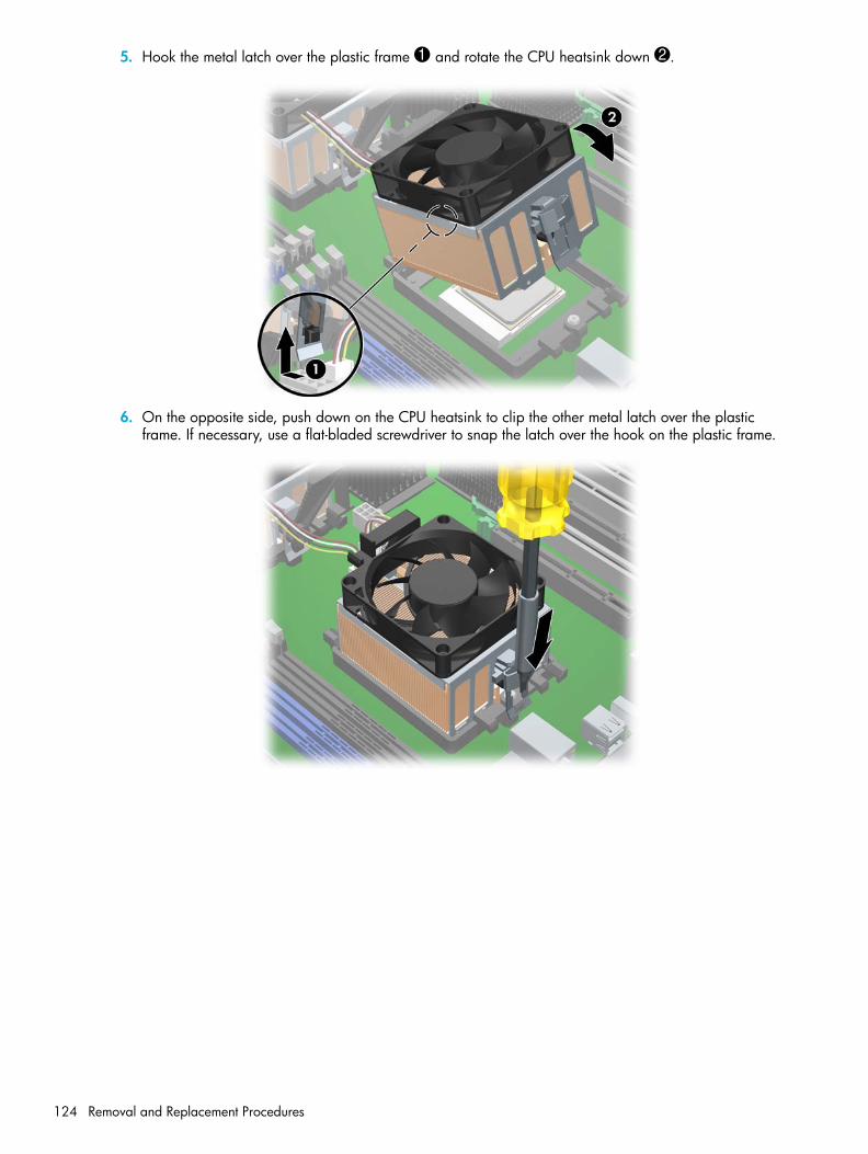
5. Hook the metal latch over the plastic frame 1 and rotate the CPU heatsink down 2.
6. On the opposite side, push down on the CPU heatsink to clip the other metal latch over the plastic frame. If necessary, use a flat-bladed screwdriver to snap the latch over the hook on the plastic frame.
Removal and Replacement Procedures124

Rem
oval
and
Rep
lace
men
t Pr
oced
ures
7. Rotate the latch lever down 1 until it snaps to the plastic frame.
8. Connect the CPU heatsink cable to the white processor fan connector 2.
CAUTION: If the CPU heatsink cable does not reach the fan connector, you have installed the CPU heatsink backwards.
9. Double check and be sure the latch lever is snapped to the plastic frame correctly. The lever must attach to the plastic frame exactly as shown in the following illustration.
CAUTION: If the CPU heatsink is not properly connected, the hardware could become disengaged from the system board and damage your system.
Removal and Replacement of Components 125

10.Lower the CPU airflow duct over the CPU heatsinks until it snaps into place.
NOTE: The CPU airflow duct is only required when two processors are installed.
NOTE: The CPU airflow duct more easily installs if the memory duct is temporarily removed first.
11.Install the front fan (page 103).
Removal and Replacement Procedures126

Rem
oval
and
Rep
lace
men
t Pr
oced
ures
ProcessorTo remove the processor:
1. Disconnect power from the system (page 79), remove the access panel (page 86), and remove the CPU heatsink (page 116).
2. Raise the processor socket handle fully (the full swing angle of the lever is approximately 90 degrees).
3. Pull the processor straight out of the socket.
CAUTION: Handle the processor carefully. To avoid bending the processor pins, keep the processor perfectly flat when removing and storing it.
NOTE: Store the processor in a safe place where it will not be damaged. If you are permanently removing a second processor, check your OS documentation to determine if you should change any OS settings to disable multiprocessor support.
Removal and Replacement of Components 127

To replace the processor:
1. Disconnect power from the system (page 79), remove the access panel (page 86), remove the CPU heatsink (page 116), and remove the processor (page 127).
2. Raise the processor socket handle fully (the full swing angle of the lever is approximately 90 degrees).
CAUTION: Processor pins are delicate and bend easily. Use extreme care when placing the processor in the socket.
3. Line up the triangle on the top of the processor with the triangle on the corner of the processor socket and install the processor into the socket. Ensure that the underside of the processor is level with the top of the processor socket. Lightly press down on the top of the processor while closing the socket lever.
4. Check for proper processor seating in the socket by carefully trying to lift the processor out of the socket with your fingers. A properly seated processor does not lift out of the socket.
5. Replace the CPU heatsink (page 116).
Removal and Replacement Procedures128

Rem
oval
and
Rep
lace
men
t Pr
oced
ures
System BoardTo remove the system board:
1. Disconnect power from the system (page 79), remove the access panel (page 86), remove all plug-in cards and graphics cards (page 100), remove the memory duct (page 92), remove the CPU heatsinks airflow duct (page 116), if installed, and remove the system fan assembly (page 93).
2. Disconnect all cabling from the system board.
NOTE: Make note of the cable connections before disconnecting them from the system board. Refer to “Power Connections to Drives” on page 106 for more information.
3. Turn the green lever 1 clockwise to disengage the system board from the chassis.
4. Push the system board forward and lift it out 2 of the chassis.
To replace the system board:
1. Insert the system board straight down and make sure all standoffs engage with the keyholes in the chassis.
NOTE: Be sure the system board connectors engage correctly with the rear I/O panel.
2. Push back on the board while maintaining downward pressure, so all standoffs remain engaged.
3. Turn the green lever counter-clockwise to engage the system board with the chassis.
Removal and Replacement of Components 129

Removal and Replacement Procedures130

Syste
m D
iagn
ostic
s an
d Tr
oubl
esho
otin
g
5 System Diagnostics and Troubleshooting
This chapter discusses the tools available for diagnosing and troubleshooting system issues.
• “E-Support” on page 132
• “Troubleshooting Checklist” on page 133
• “LED Color Definitions” on page 134
• “HP Insight Diagnostics Offline Edition” on page 135
• “Diagnostic Light Codes” on page 140
• “Troubleshooting Scenarios and Solutions” on page 142
• “Power On Self Test (POST) and Error Messages” on page 165
131

E-Support
Help & Support Center (HSC) and E-SupportHSC provides online access to technical support information, software updates and downloads, diagnostic tools, and HP support contact information.
To open HSC from your desktop, click Start > Help and Support.
HSC contains four sections:
• HP Product Information (requires Internet access)—Links to the HP Technical Support Web site for your product. You can access all related documentation, downloads and updates, tools, and more.
• HP Software & Driver Downloads (requires Internet access)—Links to HP specific software downloads and updates.
• HP Support Tools (requires Internet access)—Links to self-help tools and diagnostics offered by HP Instant Support Professional Edition.
• Contact HP for Support—Provides two different options:
• Chat with an expert online (requires Internet access)—Provides a tool to communicate with a support specialist online through Active Chat.
• Call a support agent—Provides hardware details about the workstation and HP support contact phone number worldwide.
System Diagnostics and Troubleshooting132

Syste
m D
iagn
ostic
s an
d Tr
oubl
esho
otin
g
Troubleshooting ChecklistBefore running any of the diagnostic utilities, go through the following checklist to find possible solutions for workstation or software problems.
• Are the workstation and monitor connected to a working electrical outlet?
• Is the workstation turned on?
• Is the green power light illuminated?
• Is the monitor turned on?
• Is the green monitor light illuminated?
• Turn up the monitor brightness and contrast controls if the monitor is dim.
• Press and hold any key. If the system beeps, then the keyboard is operating correctly.
• Check all cables for loose or incorrect connections.
• Reconfigure the workstation after installing a non-PnP expansion board or other option, such as a diskette drive.
• Are all of the necessary device drivers installed?
• Have all printer drivers been installed for each application?
• Remove all diskettes and CDs from the drives before you turn on the system.
• Are you running the latest BIOS version, drivers, and software updates?
Troubleshooting Checklist 133

LED Color DefinitionsAn LED light exists on the front panel of your workstation. The following table describes what each color signifies.
Table 5-21 LED Color Definitions
LED State LED Color System Status
Solid Green System is on.
Blinking Green System is in Standby.
Solid or Blinking Red System has error.
None No light System is in Hibernate or it is off.
System Diagnostics and Troubleshooting134

Syste
m D
iagn
ostic
s an
d Tr
oubl
esho
otin
g
HP Insight Diagnostics Offline EditionNOTE: HP Insight Diagnostics is included on CD with some computer models only.
The HP Insight Diagnostics utility allows you to view information about the hardware configuration of the computer and perform hardware diagnostic tests on the subsystems of the computer. The utility simplifies the process of effectively identifying, diagnosing, and isolating hardware issues.
The Survey tab is displayed when you invoke HP Insight Diagnostics. This tab shows the current configuration of the computer. From the Survey tab, there is access to several categories of information about the computer. Other tabs provide additional information, including diagnostic test options and test results. The information in each screen of the utility can be saved as an HTML file and stored on a diskette or USB HP Drive Key.
Use HP Insight Diagnostics to determine if all the devices installed on the computer are recognized by the system and functioning properly. Running tests is optional but recommended after installing or connecting a new device.
You should run tests, save the test results, and print them so that you have printed reports available before placing a call to the Customer Support Center.
NOTE: Third party devices might not be detected by HP Insight Diagnostics.
Key Features and BenefitsHP Insight Diagnostics simplifies the process of effectively identifying, diagnosing, and isolating the hardware issues.
In addition to robust management tools, service tools can be invaluable in quickly resolving system problems. To streamline the service process and resolve problems quickly, it is necessary to have the right information available at the time that a service call is placed. Before calling, write down the configuration of the system. Insight Diagnostics helps provide higher system availability. Typical uses of the Insight Diagnostics are:
• Testing and diagnosing apparent hardware failures
• Documenting system configurations for upgrade planning, standardization, inventory tracking, disaster recovery, and maintenance
• Sending configuration information to another location for more in-depth analysis
Theory of OperationInsight Diagnostics Offline Edition operates in offline mode only. The operating system is not running and software information from the system is not available to the diagnostics.
Offline Survey—displays the current system configuration.
Insight Diagnostics Test—provides the capability to test functionality of all the major hardware components in the system. The Test feature is designed to be flexible to enable the user to customize test selections by providing different modes and types of testing.
HP Insight Diagnostics Offline Edition 135
Quick Test—provides a predetermined script where a sample of each hardware component is exercised and requires no user intervention.
Complete Test—provides a predetermined script where each hardware component is fully tested. You can select Interactive or Unattended tests. This will change the devices tested during the Complete Test. There are more tests available in the interactive mode, but these require user intervention.
Custom Test—provides the most flexibility in controlling the testing of a system. The Custom Test mode enables the user to specifically select which devices, tests, and test parameters are run. Users are provided the ability to select tests that do not require any user interaction through the Interactive and Unattended tests modes.
Diagnostic Utility on CDHP Insight Diagnostics is available on the Documentation and Diagnostics CD that was shipped with your HP Workstation.
To start the diagnostic utility on the Documentation and Diagnostics CD:
1. Insert the Documentation and Diagnostics CD into the workstation.
2. Restart your workstation and press the F9 key when the F10=Setup message appears on the screen.
3. After POST is completed, a list of bootable devices is displayed. Use the arrow keys to select the CD-ROM Drive and press Enter. The workstation then boots from the selected non-default device for this one time.
4. When the system boots, HP Insight Diagnostics launches automatically.
Download the ISO ImageTo download the latest diagnostic utility:
1. Visit http://www.hp.com/go/workstationsupport.
2. Select your HP Workstation.
3. Click the download driver and software link.
4. Select your OS.
5. Click the Diagnostic link.
6. Locate HP Insight Diagnostics and click Download.
NOTE: The downloaded file includes instructions on creating the bootable CD.
User Interface
NavigationThe Insight Diagnostics home page contains the following tabs: Survey, Test, Status, and Log. These tabs separate the major functions of Insight Diagnostics.
System Diagnostics and Troubleshooting136
Syste
m D
iagn
ostic
s an
d Tr
oubl
esho
otin
g
Survey TabWhen the Survey tab is selected, the Survey menu displays and enables you to view important system configuration information. The Summary view limits the amount of data displayed, while the Advanced view shows all the data in the selected category. Regardless of whether you choose Advanced or Summary, the following categories of information are available on the Survey menu:
• All—Gives a listing of all categories of information about the computer.
• Overview—Gives you a listing of general information about the computer.
• Architecture—Provides system BIOS and PCI device information.
• Asset Control—Shows asset tag, system serial number, and processor information.
• Communication—Shows information about the computer parallel (LPT) and serial (COM) port settings, plus USB and network controller information.
• Graphics—Shows information about the graphics controller of the computer.
• Input Devices—Shows information about the keyboard, mouse, and other input devices connected to the computer.
• Memory—Shows information about all memory in the computer. This includes memory slots on the system board and any memory modules installed.
• Miscellaneous—Shows information obtained from the computer configuration memory (CMOS), system management BIOS data, system board data, and diagnostics component information.
• Storage—Shows information about storage media connected to the computer. This list includes all fixed disks, diskette drives, and optical drives.
• System—Shows information about the system board, processor, chassis, and BIOS, plus internal speaker and PCI bus information.
• Multimedia—Shows information about the system Audio devices
Test TabThe Test tab allows you to choose various parts of the system to test. You can also choose the type of test and testing mode.
There are two test modes to choose from:
• Interactive Mode—Provides maximum control over the testing process. The diagnostic software will prompt you for input during tests that require your interaction.You may also determine whether the test passed or failed.
• Unattended Mode—Does not display prompts and requires no interaction. If errors are found, they are displayed when testing is complete.
The Insight Diagnostics utility provides the capability to test all the major pieces of hardware in the system. You can select from several types of tests:
• Quick Test—Provides a predetermined script where a sample of each hardware component is exercised and requires no user intervention.
• Complete Test—Provides a predetermined script where each hardware component is fully tested. You can select Interactive or Unattended tests. This will change the devices tested during the Complete Test. There are more tests available in the interactive mode, but these require user intervention.
• Custom Test—Provides the most flexibility in controlling the testing of a system. The Custom Test mode allows the user to specifically select which devices, tests, and test parameters are run. Users are provided the ability to select tests that do not require any user interaction through the Interactive and Unattended test modes.
HP Insight Diagnostics Offline Edition 137

To begin testing:
1. Select the Test tab.
2. On the left side of the tab, select the Type of Test to perform (Quick, Complete, or Custom).
3. On the left side of the tab, select the Test Mode (Interactive or Unattended).
4. Select the device to be tested from the drop-down list.
5. Choose how you want the test to be executed, either Number of Loops or Total Test Time. When choosing to run the test over a specified number of loops, enter the number of loops to perform. If you desire to have the diagnostic test for a specified time period, enter the amount of time in minutes.
6. Click Begin Testing to start the test. The Status tab, which allows you to monitor the progress of the test, is automatically displayed during the testing process. When the test is complete, the Status tab shows whether the device passed or failed.
7. If errors are found, go to the Log tab and click the Error Log to display more detailed information and recommended actions.
Status TabThe Status tab displays the status of the selected tests. The type of test executed (for example, Quick, Complete, Custom) is displayed. The main progress bar displays the percent complete of the current set of tests. While testing is in progress a Cancel Testing button, which will cancel the test job, is displayed.
After testing has completed, the Cancel Testing button is replaced with a Retest button. The Retest button will retest the last set of tests executed. This enables you to re-run the set of tests without having to go back to the test selection page.
The Status page also shows:
• The devices being tested.
• The tests that are running.
• The overall elapsed time.
• The individual elapsed test times.
• The condition status of each test.
Log TabThe Log tab contains two logs, a Test Log and an Error Log, each of which can be selected from the left side of the tab.
The Test Log displays all tests that have been executed, the number of times of execution, the number of times the test failed, and the time it took to complete the test. The Clear Test Log button will clear the contents of the Test Log.
The Error Log displays the tests for devices that have failed during the diagnostic testing and includes the following columns of information.
• The Description section describes the error that the diagnostic test found.
• The Recommended Repair will give a recommended action that should be performed to resolve the failed hardware.
• The Failed Count is the number of times the test has failed.
• The Error Code provides a numerical code for the failure.
• The Clear Error Log button will clear the contents of the Error Log.
System Diagnostics and Troubleshooting138

Syste
m D
iagn
ostic
s an
d Tr
oubl
esho
otin
g
Saving and Printing Information in HP Insight Diagnostics You can save the information displayed in the HP Insight Diagnostics Status and Log tabs to a diskette or a USB 2.0 HP Drive Key (64MB or higher). You cannot save to the hard drive. The system will automatically create an html file that has the same appearance as the information displayed on the screen.
1. Insert a diskette or USB 2.0 HP Drive Key (capacity must be 64MB or higher). USB 1.0 Drive Keys are not supported.
2. Click Save in the upper-right corner of the tab.
3. Select Save to the floppy or Save to USB key.
4. Enter a file name in the File Name box and click the Save button. An html file will be saved to the inserted diskette or USB HP Drive Key.
5. Print the information from the storage device used to save it.
NOTE: To exit HP Insight Diagnostics, click Exit in the upper-right corner of the screen then remove the Documentation and Diagnostics CD from the optical drive.
HP Insight Diagnostics Offline Edition 139

Diagnostic Light CodesThis sections provides an overview of the diagnostic lights that are related to your workstation.
NOTE: The beeps are heard through the on-board piezo speaker and not the chassis speaker. The blinking lights and beeps repeat for five cycles. After that, only the blinking lights repeat.
Table 5-22 Diagnostic Light Codes
Chassis Indicator Lights
Power LED and Sound Activity Diagnosis and Service Action
None System does not power on.Press the power button. If the HDD LED is green:1. Check that the power supply cables are properly connected to the system board.2. Remove the expansion cards one at a time.3. Replace the system board.OrPress the power button. If the HDD LED does not illuminate:1. Check that the unit is plugged into a working AC outlet.2. Check that the power button harness is properly connected to the in-line front
panel I/O device assembly connector.3. Check that the power supply cables are properly connected to the system board.4. Check the power supply functionality.
a. Disconnect the AC power.b. Remove all internal power supply cables from the system board.c. Plug in the AC power.
• If the power supply fan spins and the BIST LED lights, the power supply is functional. Replace the system board.
• If the power supply fan does not spin or the BIST LED does not light, replace the power supply.
Beeps and blinks RED two times
Thermal shutdown:1. Ensure the workstation air vents are not blocked and the cooling fans are
running.2. Press the power button, and see if the fans on the CPU heatsinks spin. If they are
not spinning, ensure the fan cable is plugged into the system board. Ensure the CPU heatsinks are properly seated.
3. If the CPU heatsinks are plugged in and seated but are not spinning, replace the CPU heatsinks.
4. Reseat the CPU heatsinks and verify the fan assemblies are properly attached.
Beeps and blinks RED 3 times CPU is not installed:1. Install CPU.2. Reseat CPU.
System Diagnostics and Troubleshooting140

Syste
m D
iagn
ostic
s an
d Tr
oubl
esho
otin
g
Beeps and blinks RED 4 times Power supply failure:1. Locate the faulty device by removing all devices and then reinstalling one at atime until workstation fails. Replace the device causing the failure. Continue adding devices to ensure all are functioning properly.
2. Check the power supply functionality.a. Disconnect AC power.b. Remove all internal power supply cables from the system board.c. Plug in AC power.
• If the power supply fan spins and the BIST LED lights, then the power supply is functional. Replace the system board.
• If the power supply fan does not spin or the BIST LED does not light, replace the power supply.
Beeps and blinks RED 5 times Pre-video memory error:1. Reseat memory modules.2. Replace memory modules one at a time to find the faulty module.3. Replace third-party modules with HP memory.4. Replace system board.
Beeps and blinks RED 6 times Pre-video graphics card error:For systems with integrated graphics, replace the system board.For systems with graphic cards: 1. Reseat the graphics card. 2. Replace the graphics card.3. Replace the system board.
Beeps and blinks RED 7 times System board failure (ROM detected failure before video).Replace system board.
Beeps and blinks RED 8 times Invalid ROM based on bad checksum.1. Reflash the ROM.2. Replace the system board.
Beeps and blinks RED 9 times System powers on but is unable to boot.1. Replace the system board.2. Replace the processor.
Table 5-22 Diagnostic Light Codes (continued)
Chassis Indicator Lights (continued)
Power LED and Sound Activity Diagnosis and Service Action
Diagnostic Light Codes 141

Troubleshooting Scenarios and SolutionsThis section presents an extensive overview of various troubleshooting scenarios and includes possible solutions for each.
Solving Minor ProblemsTable 5-23 Solving Minor Problems
Problem Cause Possible Solution
Workstation appears locked up and does not turn off when the power button is pressed.
Software control of the power switch is not functional.
1. Press and hold the power button for at least four seconds until the workstation turns off.
2. Disconnect the electrical plug from outlet.
Workstation will not respond to USB keyboard or mouse.
Workstation is in Standby mode.
Press the power button to resume from Standby mode.
CAUTION: When attempting to resume from Standby mode, do not hold down the power button for more than four seconds. Otherwise, the workstation will shut down and you will lose your data.
Workstation seems to be locked up.
Program in use has stopped responding to commands.
1. Attempt the normal shutdown procedure. 2. Press the power button for four or more seconds to
turn off the power. 3. Restart the workstation using the power button.
Workstation date and time display is incorrect.
Real-time clock (RTC) battery might need to be replaced.
1. For Windows, open the control panel and reset the date and time.
2. Replace the RTC battery.
Workstation appears to pause periodically.
Network driver is loaded and no network connection is established.
Establish a network connection, or use Computer Setup or Microsoft Windows Device Manager to disable the network controller.
Cursor does not move using the arrow keys on the keypad.
The Num Lock key might be on.
Press the Num Lock key. The Num Lock key can be disabled (or enabled) in Computer Setup.
Poor performance is experienced.
Processor is hot. 1. Be sure airflow to the workstation is not blocked.2. Be sure the fans are connected and working
properly (some fans only operate when needed).3. Be sure the CPU heatsink is installed properly.
There is not enough memory. Add more memory.
Hard drive is full. Transfer data from the hard drive to create more space on the hard drive.
System Diagnostics and Troubleshooting142

Syste
m D
iagn
ostic
s an
d Tr
oubl
esho
otin
g
Workstation powered off automatically and beeps and blink RED twice.
Processor thermal protection activated:A fan might be blocked or not turning.OR The CPU heatsink is not properly attached to the processor.
1. Be sure workstation air vents are not blocked and the cooling fan is running.
2. Open hood, press power button, and see if the processor fan spins. If not spinning, be sure the fan’s cable is plugged onto the system board header. Be sure the fan is fully/properly seated or installed.
3. Replace the processor fan.4. Reseat CPU heatsink and verify that the fan
assembly is properly attached.
System does not power on and the LEDs on the front of the workstation are not flashing.
System is unable to power on. Press and hold the power button for less than four seconds. If the hard drive LED turns green:1. Check that the power supply cables are properly
connected to the system board.2. Remove the expansion cards.3. Replace the system board.ORPress and hold the power button for less than four seconds. If the hard drive LED does not illuminate:1. Check that the unit is plugged into a working AC
outlet.2. Open the access panel and check that the power
button harness is properly connected to the in-line front panel I/O device assembly connector.
3. Check that the power supply cables are properly connected to the system board.
4. Check the power supply functionality.a. Disconnect the AC power.b. Remove all internal power supply cables from
the system board.c. Plug in the AC power.
• If the power supply fan spins and the BIST LED lights, the power supply is functional, so replace the system board.
• If the power supply fan does not spin or the BIST LED does not light, replace the power supply.
Table 5-23 Solving Minor Problems
Problem Cause Possible Solution
Troubleshooting Scenarios and Solutions 143

Solving Power Supply Problems
Testing Power SupplyBefore replacing the power supply, use the Built-In Self-Test (BIST) feature to learn if the power supply still works.
To test the power supply:
1. Disconnect all internal power supply cables.
2. Plug in the AC power.
• If the green BIST LED on the rear of the workstation is lit AND the fan is spinning, the power supply is functional.
• If the green BIST LED is not lit OR the fan is not spinning, replace the power supply.
Table 5-24 Power Supply Problems
Problem Cause Solution
Power supply shuts down intermittently.
Power supply fault. Replace the power supply.
Workstation powered off automatically and beeps and blinks RED two times
Processor thermal protection activated:A fan might be blocked or not turning.OR The CPU heatsink assembly is not properly attached to the processor.
1. Be sure that the workstation air vents are not blocked and the cooling fan is running.
2. Open the access panel, press the power button, and see if the fan on the heatsink spins. If the fan is not spinning, be sure the heatsink cable is plugged into the system board header. Be sure the fan is properly seated or installed.
3. Replace the CPU heatsink.4. Reseat the CPU heatsink and verify that the fan
assembly is properly attached.
System Diagnostics and Troubleshooting144

Syste
m D
iagn
ostic
s an
d Tr
oubl
esho
otin
g
Power LED flashes RED once every two seconds.
Power failure (power supply is overloaded).
1. Check if a device is causing the problem by removing ALL attached devices. Power on the system. If the system enters the POST, then power off and replace one device at a time and repeat this procedure until failure occurs. Replace the device causing the failure. Continue adding devices one at a time to ensure all devices are functioning properly.
2. Check the power supply functionality.a. Disconnect the AC power.b. Remove all internal power supply cables
from the system board.c. Plug in the AC power.
• If the power supply fan spins and the BIST LED lights, the power supply is functional, so replace the system board.
• If the power supply fan does not spin or the BIST LED does not light, replace the power supply.
Table 5-24 Power Supply Problems (continued)
Problem Cause Solution
Troubleshooting Scenarios and Solutions 145
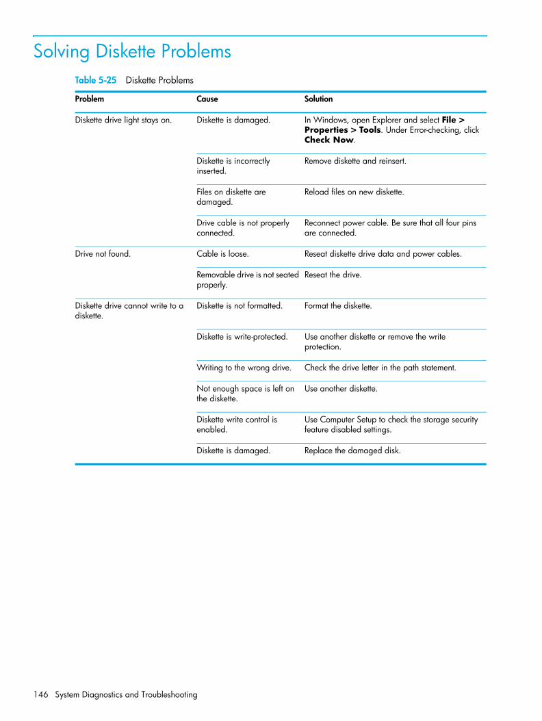
Solving Diskette ProblemsTable 5-25 Diskette Problems
Problem Cause Solution
Diskette drive light stays on. Diskette is damaged. In Windows, open Explorer and select File > Properties > Tools. Under Error-checking, click Check Now.
Diskette is incorrectly inserted.
Remove diskette and reinsert.
Files on diskette are damaged.
Reload files on new diskette.
Drive cable is not properly connected.
Reconnect power cable. Be sure that all four pins are connected.
Drive not found. Cable is loose. Reseat diskette drive data and power cables.
Removable drive is not seated properly.
Reseat the drive.
Diskette drive cannot write to a diskette.
Diskette is not formatted. Format the diskette.
Diskette is write-protected. Use another diskette or remove the write protection.
Writing to the wrong drive. Check the drive letter in the path statement.
Not enough space is left on the diskette.
Use another diskette.
Diskette write control is enabled.
Use Computer Setup to check the storage security feature disabled settings.
Diskette is damaged. Replace the damaged disk.
System Diagnostics and Troubleshooting146

Syste
m D
iagn
ostic
s an
d Tr
oubl
esho
otin
g
Cannot format diskette. Invalid media reported. When formatting a disk in MS-DOS, you might need to specify diskette capacity. For example, to format a 1.44-MB diskette, enter the following command at the MS-DOS prompt:FORMAT A: /F:1440
A problem has occurred with a disk transaction.
The directory structure is bad, or there is a problem with a file.
In Windows, right-click Start > Explore, and select a drive. Select File > Properties > Tools. Under Error-checking, click Check Now.
Diskette drive cannot read a diskette.
Diskette is not formatted. Format the diskette.
You are using the wrong diskette type for the drive type.
Check the type of drive that you are using and use the correct diskette type.
You are reading the wrong drive.
Check the drive letter in the path statement.
Diskette is damaged. Replace the diskette with a new one.
“Invalid system disk” message is displayed.
A diskette that does not contain the system files needed to start the workstation has been inserted in the drive.
When drive activity stops, remove the diskette and press the Spacebar. The workstation should start up.
Diskette error has occurred. Restart the workstation by pressing the power button.
Cannot Boot from Diskette. Diskette is not bootable. Replace with a bootable diskette.
Diskette boot has been disabled in Computer Setup.
Run Computer Setup and enable diskette boot in Storage > Boot Order.
Removable media boot has been disabled in Computer Setup.
Run Computer Setup and enable Removable Media Boot in Storage > Storage Options.
Table 5-25 Diskette Problems (continued)
Problem Cause Solution
Troubleshooting Scenarios and Solutions 147

Solving Hard Drive ProblemsTable 5-26 Hard Drive Problems
Problem Cause Solution
Hard drive error occurs. Hard disk has bad sectors or has failed.
Use a utility to locate and block usage of bad sectors. If necessary, reformat the hard disk.
Disk transaction problem. Either the directory structure is bad or there is a problem with a file.
In Windows, open Explorer, select a drive, and select File > Properties > Tools. Under Error-checking, click Check Now.
Drive not found (identified). Loose cable. Check cable connections.
The system might not have automatically recognized a newly installed device.
1. Run Computer Setup.2. If the system still does not recognize the new
device, check to see if the device is listed within Computer Setup. If it is listed, the probable cause is a driver problem. If it is not listed, the probable cause is a hardware problem.
3. If this is a newly installed drive, enter Setup and try adding a POST delay under Advanced > Power-On.
Drive’s SATA controller is disabled in Computer Setup.
Run Computer Setup and enable the SATA controllers in Storage>Storage Options.
Drive’s SCSI controller is disabled in Computer Setup.
Run Computer Setup and enable the SCSI controllers in Storage>Storage Options.
Drive responds slowly immediately after power-up.
Run Computer Setup and increase the POST Delay in Advanced > Power-On Options.
Nonsystem disk/NTLDR missing message.
System is trying to start from a non-bootable diskette.
Remove the diskette from the diskette drive.
System files missing or not properly installed.
1. Insert a bootable system diskette and restart.2. Verify hard drive is partitioned and formatted. 3. Install system files for the appropriate operating
system, if necessary.
Hard drive boot disabled in Computer Setup.
Run Computer Setup and enable the hard drive entry in the Storage Options list.
Workstation does not start. Hard drive is damaged. Observe the beeps and LED lights on the front of the workstation. Refer to “Power On Self Test (POST) and Error Messages” on page 165.
System Diagnostics and Troubleshooting148

Syste
m D
iagn
ostic
s an
d Tr
oubl
esho
otin
g
Solving Display ProblemsTable 5-27 Display Problems
Problem Cause Solution
Blank screen (no video). The cable connections are not correct.
Check the cable connections from the monitor to the workstation and to a working electrical outlet.
The monitor is off. Switch the monitor to on (LED is on). You might need to refer to the monitor manual for an explanation of the LED signals.
Screen blanking utility installed or energy saver features enabled.
Press any key or click the mouse button and, if set, enter your password.
System ROM is bad; system is running in FailSafe Boot Block mode (indicated by eight beeps).
Reflash the ROM using a ROMPaq diskette.
Computer is in Standby mode.
Press the power button to resume from Standby mode.
CAUTION: When attempting to resume from Standby mode, do not hold down the power button for more than four seconds. Otherwise, the workstation will shut down and you will lose your data.
Monitor settings in the workstation are not compatible with the monitor.
1. Restart the workstation and press F8 during startup when you see “Press F8” in the bottom-right corner of the screen.
2. Using the keyboard arrow keys, select Enable VGA Mode and press Enter.
3. In Windows Control Panel, double-click the Display icon and select the Settings tab.
4. Use the sliding control to reset the resolution.
The display works properly during the POST but goes blank when the OS starts.
The display settings in the OS are incompatible with your graphics card and monitor.
1. Restart your workstation in VGA mode.2. After the OS starts, change the display settings
to match those supported by your graphics card and monitor.
3. Refer to your OS and graphics card documentation for information on changing display settings.
Power LED flashes Red six times, once every second, followed by a two second pause, and the workstation beeps six times.
Pre-video graphics error. For systems with a graphics card:1. Reseat the graphics card. 2. If using PCI Express card with auxiliary power
cable, be sure it is attached.3. Replace the graphics card.4. Replace the system board.
Troubleshooting Scenarios and Solutions 149
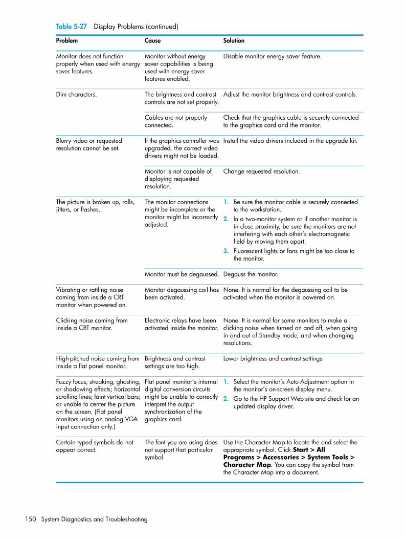
Monitor does not function properly when used with energy saver features.
Monitor without energy saver capabilities is being used with energy saver features enabled.
Disable monitor energy saver feature.
Dim characters. The brightness and contrast controls are not set properly.
Adjust the monitor brightness and contrast controls.
Cables are not properly connected.
Check that the graphics cable is securely connected to the graphics card and the monitor.
Blurry video or requested resolution cannot be set.
If the graphics controller was upgraded, the correct video drivers might not be loaded.
Install the video drivers included in the upgrade kit.
Monitor is not capable of displaying requested resolution.
Change requested resolution.
The picture is broken up, rolls, jitters, or flashes.
The monitor connections might be incomplete or the monitor might be incorrectly adjusted.
1. Be sure the monitor cable is securely connected to the workstation.
2. In a two-monitor system or if another monitor is in close proximity, be sure the monitors are not interfering with each other’s electromagnetic field by moving them apart.
3. Fluorescent lights or fans might be too close to the monitor.
Monitor must be degaussed. Degauss the monitor.
Vibrating or rattling noise coming from inside a CRT monitor when powered on.
Monitor degaussing coil has been activated.
None. It is normal for the degaussing coil to be activated when the monitor is powered on.
Clicking noise coming from inside a CRT monitor.
Electronic relays have been activated inside the monitor.
None. It is normal for some monitors to make a clicking noise when turned on and off, when going in and out of Standby mode, and when changing resolutions.
High-pitched noise coming from inside a flat panel monitor.
Brightness and contrast settings are too high.
Lower brightness and contrast settings.
Fuzzy focus; streaking, ghosting, or shadowing effects; horizontal scrolling lines; faint vertical bars; or unable to center the picture on the screen. (Flat panel monitors using an analog VGA input connection only.)
Flat panel monitor’s internal digital conversion circuits might be unable to correctly interpret the output synchronization of the graphics card.
1. Select the monitor’s Auto-Adjustment option in the monitor’s on-screen display menu.
2. Go to the HP Support Web site and check for an updated display driver.
Certain typed symbols do not appear correct.
The font you are using does not support that particular symbol.
Use the Character Map to locate the and select the appropriate symbol. Click Start > All Programs > Accessories > System Tools > Character Map. You can copy the symbol from the Character Map into a document.
Table 5-27 Display Problems (continued)
Problem Cause Solution
System Diagnostics and Troubleshooting150

Syste
m D
iagn
ostic
s an
d Tr
oubl
esho
otin
g
Solving Audio ProblemsTable 5-28 Audio Problems
Problem Cause Solution
Sound does not come out of the speaker or headphones.
Software volume control is turned down.
Double-click the Speaker icon on the taskbar and use the volume slider to adjust the volume.
The external speakers are not turned on.
Turn on the external speakers.
External speakers plugged into the wrong audio jack.
See the sound card documentation for proper speaker connection.
Audio cable is not connected.
Connect the audio cable between the CD or DVD-ROM drive and the system board.
Digital CD audio is not enabled.
Enable digital CD audio:1. Open the Control Panel and select System.2. On the Hardware tab, click the Device
Manager button.3. Right-click the CD/DVD device and select
Properties.4. On the Properties tab, be sure “Enable digital
CD audio for this CD-ROM device” is selected.
Headphones or devices connected to the line-out connector mute the internal speaker.
Turn on and use headphones or external speakers, if connected, or disconnect headphones or external speakers.
Volume is muted. 1. Open the Control Panel, click Sound, Speech and Audio Devices, then click Sounds and Audio Devices.
2. Deselect the Mute checkbox.
Computer is in Standby mode.
Press the power button to resume from Standby mode.
CAUTION: When attempting to resume from Standby mode, do not hold down the power button for more than four seconds. Otherwise, the workstation will shut down and you will lose your data.
Noise or no sound comes out of the speakers or headphones.
1. If using digital speakers that have a stereo jack and want the system to auto-switch to digital, use a stereo-to-mono adapter to properly engage the auto-sense feature or use the multimedia device properties to manually switch the audio signal from analog to digital.
2. If the headphones have a mono jack, use the multimedia device properties to switch the system to analog out.
Troubleshooting Scenarios and Solutions 151
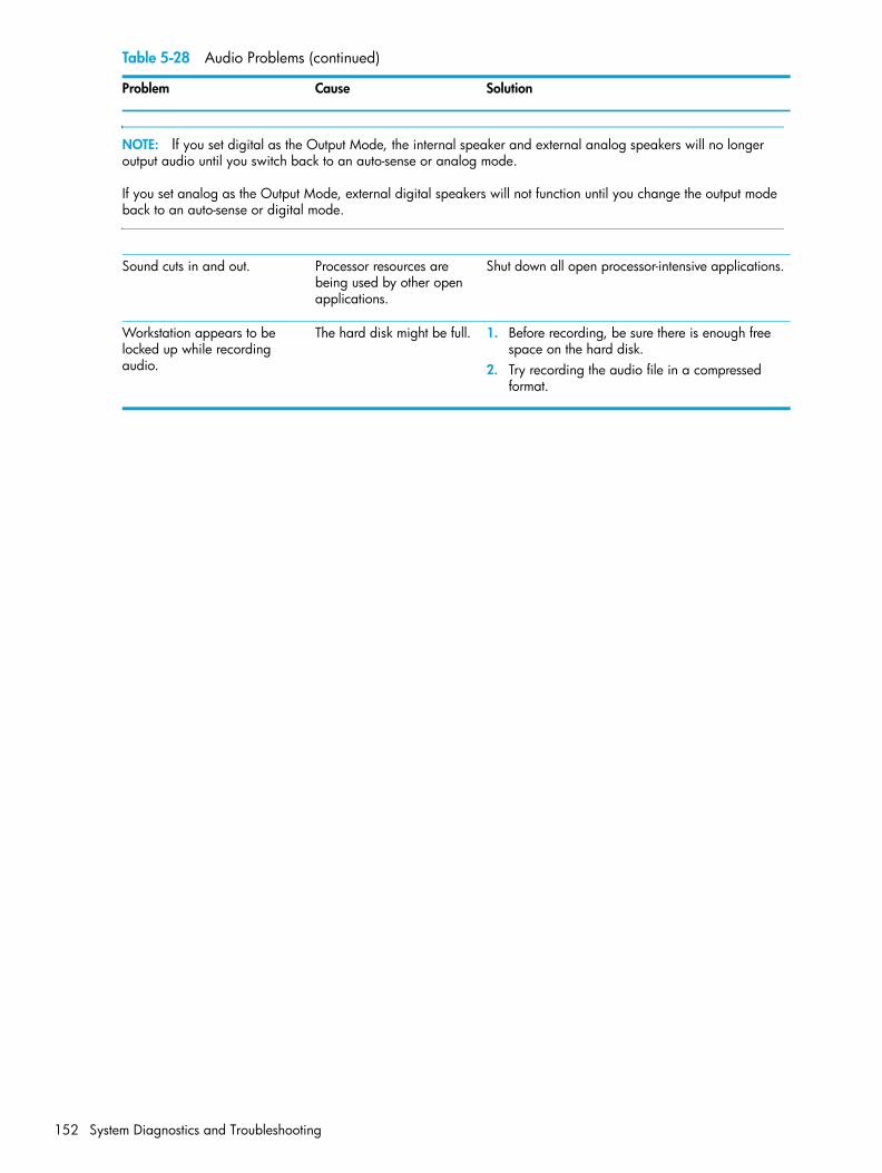
NOTE: If you set digital as the Output Mode, the internal speaker and external analog speakers will no longer output audio until you switch back to an auto-sense or analog mode.
If you set analog as the Output Mode, external digital speakers will not function until you change the output mode back to an auto-sense or digital mode.
Sound cuts in and out. Processor resources are being used by other open applications.
Shut down all open processor-intensive applications.
Workstation appears to be locked up while recording audio.
The hard disk might be full. 1. Before recording, be sure there is enough free space on the hard disk.
2. Try recording the audio file in a compressed format.
Table 5-28 Audio Problems (continued)
Problem Cause Solution
System Diagnostics and Troubleshooting152

Syste
m D
iagn
ostic
s an
d Tr
oubl
esho
otin
g
Solving Printer ProblemsTable 5-29 Printer Problems
Problem Cause Solution
Printer does not print. Printer is not turned on and online.
Turn the printer on and be sure it is online.
Printer is out of paper. Add paper to printer.
The correct printer driver for the application are not installed.
1. Install the correct printer driver for the application.
2. Try printing using the MS-DOS command:DIR C:\ > [printer port]
where [printer port] is the address of the printer being used. If the printer works, reload the printer driver.
If you are on a network, you might not have made the connection to the printer.
Make the proper network connections to the printer.
Printer might have failed. Run printer self-test.
Printer does not turn on. The cables might not be connected properly.
Reconnect all cables.
Printer prints garbled information.
The correct printer driver is not installed.
Install the correct printer driver for the application.
The cables might not be connected properly.
Reconnect all cables.
Printer memory might be overloaded.
Reset the printer by turning it off for one minute, then turn it back on.
Troubleshooting Scenarios and Solutions 153

Solving Keyboard and Mouse ProblemsTable 5-30 Keyboard and Mouse Problems
Problem Cause Solution
Keyboard commands and typing are not recognized by the workstation.
Keyboard connector is not properly connected.
1. Shut down the workstation.2. Reconnect the keyboard to the back of the
workstation and restart the workstation.
Program in use has stopped responding to commands.
Shut down the workstation using the mouse and then restart the workstation.
Keyboard needs repairs. Replace the keyboard.
Keyboard key is stuck down. Remove any debris from the keyboard.
Workstation is in Standby mode.
Press the power button to resume from Standby mode.
WARNING! When attempting to resume from Standby mode, do not hold down the power button for more than four seconds. Otherwise, the workstation will shut down and you will lose your data.
Cursor will not move using the arrow keys on the keypad.
The Num Lock key might be on.
Press the Num Lock key. The Num Lock light should not be on if you want to use the arrow keys. The Num Lock key can be disabled (or enabled) in Computer Setup.
Mouse does not respond to movement or is too slow.
Mouse connector is not properly plugged into the back of the workstation.
1. Shut down the workstation using the keyboard.2. Plug the mouse connector into the PS/2 mouse
connector slot in the workstation and restart the workstation.
You need to increase mouse acceleration.
1. In Windows, click Start > Control Panel and double-click Mouse.
2. Select the Motion tab and adjust the speed.
Program in use has stopped responding to commands.
Shut down the workstation using the keyboard and then restart the workstation.
Mouse needs repairs. Replace the mouse.
Workstation is in Standby mode.
Press the power button to resume from Standby mode.
CAUTION: When attempting to resume from Standby mode, do not hold down the power button for more than four seconds. Otherwise, the workstation will shut down and you will lose your data.
Mouse will only move vertically or horizontally, or movement is jerky.
Mouse roller ball is dirty. Remove roller ball cover from the bottom of the mouse and clean it.
System Diagnostics and Troubleshooting154

Syste
m D
iagn
ostic
s an
d Tr
oubl
esho
otin
g
Solving Front Panel Component ProblemsIf you are experiencing problems with one of the front panel ports, you might be able to try your device in the corresponding port on the back side of the computer. If this does not fix the problem, or you must use the front panel ports, continue troubleshooting.
Some problems in this section are also discussed in other troubleshooting suggestions in this chapter.
Table 5-31 Front Panel Component Problems
Problem Cause Solution
A USB device, headphone, or microphone is not recognized by the workstation.
It is not properly connected. Reconnect the device to the front of the workstation and restart the workstation.
The device does not have power.
If the USB device requires AC power, be sure one end is connected to the device and one end is connected to a live outlet.
The correct device driver is not installed.
1. Install the correct driver for the device.2. You might need to reboot the workstation.
The cable from the device to the computer does not work.
If possible, replace the cable.
The device is not working. Replace the device.
A USB, audio, and IEEE-1394 devices are not working.
The internal cables might not be connected to the system board or the PCI card.
1. Turn off the workstation.2. Connect the cables correctly.
A device in the IEEE-1394 port is not responsive.
Cables of new external device are loose or power cables are unplugged.
Be sure that all cables are properly and securely connected.
The power switch on the device is not turned on.
Turn off the workstation, turn on the external device, then turn on the workstation to integrate the device with the workstation system.
Troubleshooting Scenarios and Solutions 155

Solving Hardware Installation ProblemsYou might need to reconfigure the workstation when you add or remove hardware, such as an additional diskette drive. If you install a PnP device, Windows XP automatically recognizes the device and configures the workstation. If you install a non-PnP device, you must reconfigure the workstation after completing installation of the new hardware. In Windows XP, use the Add Hardware Wizard and follow the on-screen instructions.
Table 5-32 Hardware Installation Problems
Problem Cause Solution
A new device is not recognized as part of the system.
Device is not seated or connected properly.
Be sure that the device is properly and securely connected and that pins in the connector are not bent down.
Cables of new external device are loose or power cables are unplugged.
Be sure that all cables are properly and securely connected and that pins in the cable or connector are not bent down.
Power switch of new external device is not turned on.
Restart the workstation, turn on the external device, then turn on the workstation to integrate the device with the workstation system.
When the system advised you of changes to the configuration, you did not accept them.
Reboot the workstation and follow the instructions for accepting the changes.
A PnP board might not automatically configure when added if the default configuration conflicts with other devices.
Use Windows XP Device Manager to deselect the automatic settings for the board and choose a basic configuration that does not cause a resource conflict. You can also use Computer Setup to reconfigure or disable devices to resolve the resource conflict.
Device hardware is not properly jumpered or otherwise configured.
Read the device-specific configuration information and check for incorrect settings or conflicts with other devices already installed in the system.
Workstation will not start. Wrong memory modules were used in the upgrade or memory modules were installed in the wrong location.
1. Review the documentation that came with the system to determine if you are using the correct memory modules and to verify the proper installation.
2. Observe the beeps and LED lights on the front of the workstation. Refer to “Power On Self Test (POST) and Error Messages” on page 165 to determine possible causes.
Beeps and power LED flashes RED five times.
Memory is installed incorrectly or is bad.
1. Reseat DIMMs.2. Replace DIMMs one at a time to isolate the
faulty module.3. Replace third-party memory with HP memory.4. Replace the system board.
System Diagnostics and Troubleshooting156

Syste
m D
iagn
ostic
s an
d Tr
oubl
esho
otin
g
Beeps and power LED flashes RED six times.
Video card is not seated properly or is bad, or system board is bad.
For systems with a graphics card:1. Reseat the graphics card. 2. If using PCI Express card with auxiliary power
cable, be sure it is attached.3. Replace the graphics card.4. Replace the system board.
Table 5-32 Hardware Installation Problems (continued)
Problem Cause Solution
Troubleshooting Scenarios and Solutions 157

Solving Network ProblemsThese guidelines do not discuss the process of debugging the network cabling.
Table 5-33 Network Problems
Problem Cause Solution
Wake-on-LAN feature is not functioning.
Wake-on-LAN is not enabled. Use the Network control application to enable Wake-on-LAN.
Network driver does not detect network controller.
Network controller is disabled. Run Computer Setup and enable network controller.
Incorrect network driver. Check the network controller documentation for the correct driver or obtain the latest driver from the manufacturer’s Web site.
Network status link light does not turn on or it never flashes.The network status light should flash when there is network activity.
No active network is detected. Check cabling and network equipment for proper connection.
Network controller is not set up properly.
Use the Network control application to verify that the device is working properly.
Network driver is not properly loaded.
Reinstall network drivers.
System cannot autosense the network.
Disable auto-sensing capabilities and force the system into the correct operating mode.
Diagnostics reports a failure. The cable is not securely connected.
Be sure that both ends of the data cable are securely connected.
The cable is attached to the incorrect connector.
Be sure that the cable is attached to the correct connector.
There is a problem with the cable or a device at the other end of the cable.
Be sure that the cable and device at the other end are operating correctly.
Network controller interrupt is shared with an expansion board.
Under the Computer Setup Advanced menu, change the resource settings for the board.
The network controller is defective.
Replace the NIC.
Diagnostics passes, but the workstation does not communicate with the network.
Network drivers are not loaded, or driver parameters do not match current configuration.
1. Be sure the network drivers are loaded and that the driver parameters match the configuration of the network controller.
2. Be sure the correct network client and protocol is installed.
The network controller is not configured for this workstation.
Select the Network icon in the Control Panel and configure the network controller.
System Diagnostics and Troubleshooting158

Syste
m D
iagn
ostic
s an
d Tr
oubl
esho
otin
g
Network controller stopped working when an expansion board was added to the workstation.
Network controller interrupt is shared with an expansion board.
Under the Computer Setup Advanced menu, change the resource settings for the board.
The network controller requires drivers.
Verify that the drivers were not accidentally deleted when the drivers for a new expansion board were installed.
The expansion board installed is a network card (NIC) and conflicts with the embedded NIC.
Under the Computer Setup Advanced menu, change the resource settings for the board.
Network controller stops working without apparent cause.
The files containing the network drivers are corrupted.
Reinstall the network drivers, using the Restore Plus! CD.
The cable is not securely connected.
Be sure that both ends of the cable are securely attached to the correct devices.
The network controller is defective.
Replace the NIC.
New network card will not boot.
New network card might be defective or might not meet industry-standard specifications.
Install a working, industry-standard NIC, or change the boot sequence to boot from another source.
Cannot connect to network server when attempting Remote System Installation.
The network controller is not configured properly.
Verify Network Connectivity, that a DHCP Server is present, and that the Remote System Installation Server contains the NIC drivers for your NIC.
System setup utility reports unprogrammed EEPROM.
Unprogrammed EEPROM. Flash the ROM. See “ROM Flash” on page 59.
Table 5-33 Network Problems (continued)
Problem Cause Solution
Troubleshooting Scenarios and Solutions 159

Solving Memory ProblemsCAUTION: For those systems that support ECC memory, HP does not support mixing ECC and non-ECC memory. Otherwise, the system will not boot the operating system.
Table 5-34 Memory Problems
Problem Cause Solution
System will not boot or does not function properly after installing additional memory modules.
Memory module is not the correct type or speed or the new memory module is not seated properly.
Replace module with the correct industry-standard device for the workstation.
On some models, ECC and non-ECC memory modules cannot be mixed.
Out of memory error. Memory configuration might not be set up correctly.
Use the Device Manager to check memory configuration.
You have run out of memory to run the application.
Check the application documentation to determine the memory requirements.
Memory count during POST is wrong.
The memory modules might not be installed correctly.
Check that the memory modules have been installed correctly and that proper modules are used.
Insufficient memory error during operation.
Too many Terminate and Stay Resident programs (TSRs) are installed.
Delete any TSRs that you do not need.
You have run out of memory for the application.
Check the memory requirements for the application or add more memory to the workstation.
Beeps and power LED flashes RED five times.
Memory is installed incorrectly or is bad.
1. Reseat DIMMs. 2. Replace DIMMs one at a time to isolate the
faulty module.3. Replace third-party memory with HP memory.4. Replace the system board.
More than 2GB of RAM is installed, yet the 32-bit OS only sees 2GB.
Memory remapping is enabled.
Enter Computer Setup (F10) and disable memory remapping: Advanced > Chipset/Memory.
A total of 4GB of RAM is installed, yet the 32-bit OS only sees about 3GB.
A 32-bit OS is limited by 4GB of address space, and some of space is used by I/O devices.
Your options are limited. You might try using a video card that uses less on-board memory.
A 64-bit OS does not see all installed memory.
Memory remapping is disabled.
Enter Computer Setup (F10) and enable memory remapping: Advanced > Chipset/Memory.
System Diagnostics and Troubleshooting160

Syste
m D
iagn
ostic
s an
d Tr
oubl
esho
otin
g
Solving Processor Problems.
Table 5-35 Processor Problems
Problem Cause Solution
Poor performance is experienced.
Processor is hot. 1. Be sure the airflow to the workstation is not blocked.
2. Be sure the fans are connected and working properly (some fans only operate when needed).
3. Be sure the CPU heatsink is installed properly.
Power LED is RED and stays on. Processor is not seated properly or not installed.
1. Check to see that the processor is present.2. Reseat the processor.
Troubleshooting Scenarios and Solutions 161
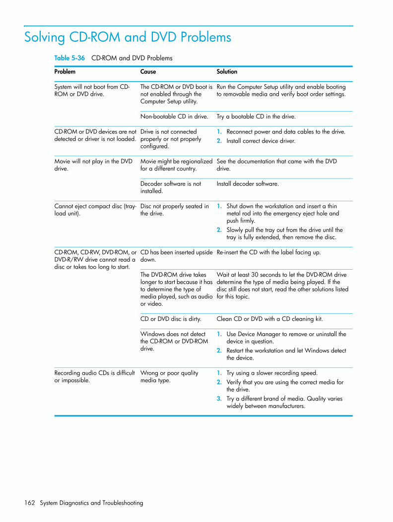
Solving CD-ROM and DVD ProblemsTable 5-36 CD-ROM and DVD Problems
Problem Cause Solution
System will not boot from CD-ROM or DVD drive.
The CD-ROM or DVD boot is not enabled through the Computer Setup utility.
Run the Computer Setup utility and enable booting to removable media and verify boot order settings.
Non-bootable CD in drive. Try a bootable CD in the drive.
CD-ROM or DVD devices are not detected or driver is not loaded.
Drive is not connected properly or not properly configured.
1. Reconnect power and data cables to the drive.2. Install correct device driver.
Movie will not play in the DVD drive.
Movie might be regionalized for a different country.
See the documentation that came with the DVD drive.
Decoder software is not installed.
Install decoder software.
Cannot eject compact disc (tray-load unit).
Disc not properly seated in the drive.
1. Shut down the workstation and insert a thin metal rod into the emergency eject hole and push firmly.
2. Slowly pull the tray out from the drive until the tray is fully extended, then remove the disc.
CD-ROM, CD-RW, DVD-ROM, or DVD-R/RW drive cannot read a disc or takes too long to start.
CD has been inserted upside down.
Re-insert the CD with the label facing up.
The DVD-ROM drive takes longer to start because it has to determine the type of media played, such as audio or video.
Wait at least 30 seconds to let the DVD-ROM drive determine the type of media being played. If the disc still does not start, read the other solutions listed for this topic.
CD or DVD disc is dirty. Clean CD or DVD with a CD cleaning kit.
Windows does not detect the CD-ROM or DVD-ROM drive.
1. Use Device Manager to remove or uninstall the device in question.
2. Restart the workstation and let Windows detect the device.
Recording audio CDs is difficult or impossible.
Wrong or poor quality media type.
1. Try using a slower recording speed.2. Verify that you are using the correct media for
the drive.3. Try a different brand of media. Quality varies
widely between manufacturers.
System Diagnostics and Troubleshooting162

Syste
m D
iagn
ostic
s an
d Tr
oubl
esho
otin
g
Solving Internet Access ProblemsTable 5-37 Internet Access Problems
Problem Cause Solution
Unable to connect to the Internet.
Internet Service Provider (ISP) account is not set up properly.
Verify Internet settings or contact the ISP for assistance.
Modem is not set up properly.
Reconnect the modem. Verify the connections are correct using the quick setup documentation.
Web browser is not set up properly.
Verify that the Web browser is installed and set up to work with your ISP.
Cable/DSL modem is not plugged in.
Plug in cable/DSL modem. You should see a “power” LED light on the front of the cable/DSL modem.
Cable/DSL service is not available or has been interrupted due to bad weather.
Try connecting to the Internet at a later time or contact your ISP. (If the cable/DSL service is connected, the “cable” LED light on the front of the cable/DSL modem will be on.)
The network cable is disconnected.
Connect the network cable between the cable modem and the workstation’s RJ-45 connector. (If the connection works, the “PC” LED light on the front of the cable/DSL modem will be on.)
IP address is not configured properly.
Contact the ISP for the correct IP address.
Cookies are corrupted. In Windows, open the Control Panel and double-click Internet Options. On the General tab, click the Delete Cookies button.
Cannot automatically launch Internet programs.
You must log on to the ISP before some programs will start.
Log on to the ISP and launch the desired program.
Troubleshooting Scenarios and Solutions 163

Internet takes too long to download Web sites.
Modem is not set up properly.
Verify that the correct modem speed and COM port are selected.For Windows:1. Open the Control Panel.2. Double-click System.3. Select the Hardware tab.4. In the Device Manager area, click the Device
Manager button.5. Double-click Ports (COM & LPT).6. Right-click the COM port your modem uses, then
click Properties.7. Under Device status, verify that the modem is
working properly.8. Under Device usage, verify the modem is
enabled.9. If there are further problems, click the
Troubleshoot button and follow the on-screen instructions.
Table 5-37 Internet Access Problems (continued)
Problem Cause Solution
System Diagnostics and Troubleshooting164

Syste
m D
iagn
ostic
s an
d Tr
oubl
esho
otin
g
Power On Self Test (POST) and Error MessagesPOST is a series of diagnostic tests that runs automatically when the system is turned on. An audible, visual, or both message occurs if the POST encounters a problem. POST checks the following items to ensure that the workstation system is functioning properly:
• Keyboard
• Memory modules
• Diskette drives
• All SATA and SCSI mass storage devices
• Processors
• Controllers
NOTE: If the Power-On Password is set, a key icon appears on the screen while POST is running. You must enter the password before continuing.
Table 5-38 POST Error Messages
Screen Message Probable Cause Recommended Action
101—Option ROM Error System ROM checksum. Verify the correct ROM.1. Flash the ROM, if needed.2. If an expansion card was recently added,
remove it and see if the problem remains. 3. Clear CMOS.4. If the message disappears, there might be
a problem with the expansion card.5. Replace the system board.
102—System Board Failure DMA, timers, etc. 1. Clear CMOS.2. Remove expansion boards.3. Replace the system board.
110—Out of Memory for Option ROMs
Option ROM for a device was unable to run due to memory constraints.
Run Computer Setup and disable unneeded devices from Advanced > Onboard Devices. Or, disable option ROMs from Advanced > Device Options.
162—System Options Not Set
Configuration incorrect. RTC battery might need to be replaced.
1. Run Computer Setup (F10 Setup).2. Set the date and time under Control Panel or
in F10 Setup depending on the operating system.
3. If the problem persists, replace the RTC battery.
163—Time and Date Not Set
Invalid time or date in configuration memory.RTC (real-time clock) battery might need to be replaced.CMOS jumper might not be properly installed.
1. Set the date and time under Control Panel or in F10 Setup depending on the operating system.
2. If the problem persists, replace the RTC battery.
Power On Self Test (POST) and Error Messages 165

164—Memory Size Error Memory configuration is incorrect. 1. Run Computer Setup (F10 Setup) or Windows utilities.
2. Be sure memory modules are installed properly.
3. If third-party memory has been added, test using HP only memory.
4. Verify proper memory module type.
201—Memory Error RAM failure. 1. Run Computer Setup (F10 Setup) or Windows utilities.
2. Be sure that memory modules are installed correctly.
3. Verify proper memory module type.4. Remove and replace memory module(s) one
at a time to isolate faulty module.5. Replace the faulty memory module(s).6. If error persists after replacing memory
modules, replace the system board.
202—Memory Type Mismatch
Memory modules do not match each other.
Replace memory modules with matched sets.
207—ECC Corrected Single Bit Errors in Memory Socket(s) y,y
Single Bit ECC error. 1. Verify proper memory module type.2. Try another memory socket.3. Replace memory module if problem persists.
212—Failed Processor Processor has failed to initialize. 1. Reseat the processor in its socket.2. If the processor does not respond, replace it.
213—Incompatible memory Module in memory Socket(s) X,X, X
A memory module in memory socket identified in the error message is missing critical SPD information, or is incompatible with the chipset.
1. Verify proper memory module type.2. Try another memory socket.3. Replace memory with a module conforming
to the SPD standard.
214—DIMM Configuration Warning
DIMMs not installed correctly (not paired correctly).
Refer to “Memory” on page 94 for the correct memory configurations and reseat the DIMMs accordingly.
215—Memory Mismatch Warning
There are one or more mismatched pairs of DIMMs between channel A and channel B. Some memory has been disabled. Install matching pairs.
Refer to “Memory” on page 94 for the correct memory configurations and reseat the DIMMs accordingly.
301—Keyboard Error Keyboard failure. 1. Reconnect keyboard with workstation turned off.
2. Check connector for bent or missing pins.3. Be sure that none of the keys are pressed.4. Replace keyboard.
303—Keyboard Controller Error
I/O board keyboard controller. 1. Reconnect keyboard with workstation turned off.
2. Replace the system board.
Table 5-38 POST Error Messages (continued)
Screen Message Probable Cause Recommended Action
System Diagnostics and Troubleshooting166
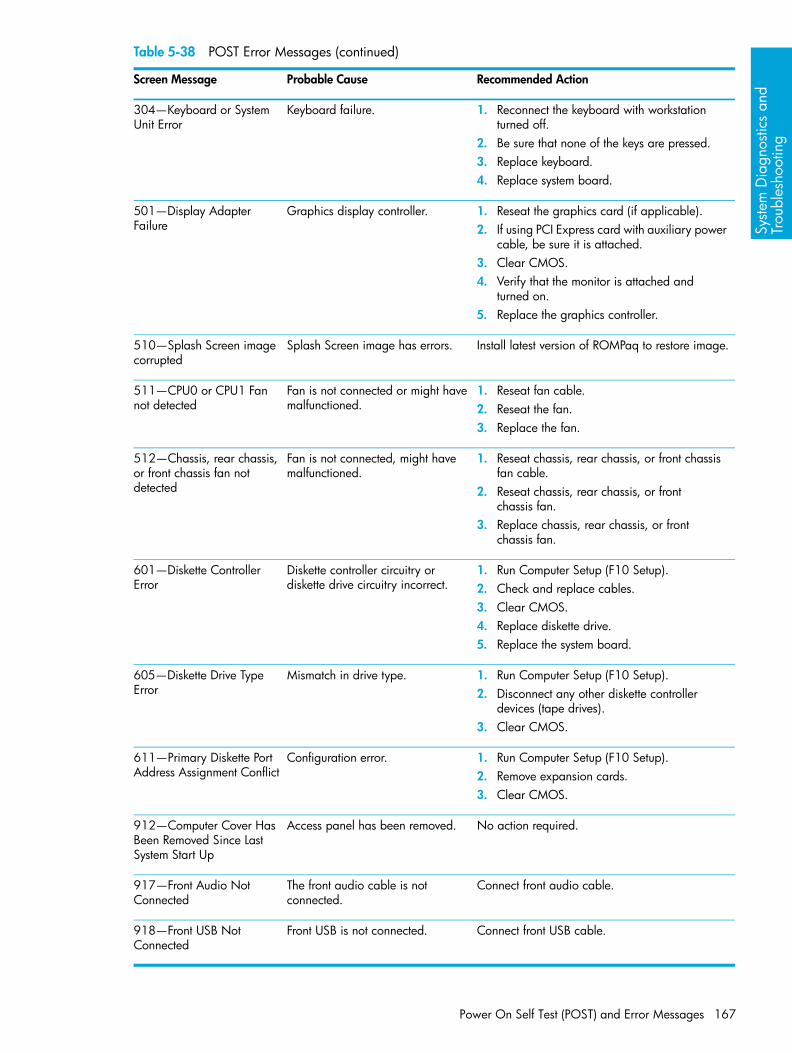
Syste
m D
iagn
ostic
s an
d Tr
oubl
esho
otin
g
304—Keyboard or System Unit Error
Keyboard failure. 1. Reconnect the keyboard with workstation turned off.
2. Be sure that none of the keys are pressed.3. Replace keyboard.4. Replace system board.
501—Display Adapter Failure
Graphics display controller. 1. Reseat the graphics card (if applicable).2. If using PCI Express card with auxiliary power
cable, be sure it is attached.3. Clear CMOS.4. Verify that the monitor is attached and
turned on.5. Replace the graphics controller.
510—Splash Screen image corrupted
Splash Screen image has errors. Install latest version of ROMPaq to restore image.
511—CPU0 or CPU1 Fan not detected
Fan is not connected or might have malfunctioned.
1. Reseat fan cable.2. Reseat the fan.3. Replace the fan.
512—Chassis, rear chassis, or front chassis fan not detected
Fan is not connected, might have malfunctioned.
1. Reseat chassis, rear chassis, or front chassis fan cable.
2. Reseat chassis, rear chassis, or front chassis fan.
3. Replace chassis, rear chassis, or front chassis fan.
601—Diskette Controller Error
Diskette controller circuitry or diskette drive circuitry incorrect.
1. Run Computer Setup (F10 Setup).2. Check and replace cables.3. Clear CMOS.4. Replace diskette drive.5. Replace the system board.
605—Diskette Drive Type Error
Mismatch in drive type. 1. Run Computer Setup (F10 Setup).2. Disconnect any other diskette controller
devices (tape drives).3. Clear CMOS.
611—Primary Diskette Port Address Assignment Conflict
Configuration error. 1. Run Computer Setup (F10 Setup).2. Remove expansion cards.3. Clear CMOS.
912—Computer Cover Has Been Removed Since Last System Start Up
Access panel has been removed. No action required.
917—Front Audio Not Connected
The front audio cable is not connected.
Connect front audio cable.
918—Front USB Not Connected
Front USB is not connected. Connect front USB cable.
Table 5-38 POST Error Messages (continued)
Screen Message Probable Cause Recommended Action
Power On Self Test (POST) and Error Messages 167

940—Extended ROM signature not found
The signature at the start of the ROM flash is missing. Your firmware (BIOS) is incomplete.
Run ROMPaq again.
960—CPU Overtemp occurred
The ambient temperature could exceed operating limits (maximum=95°F), or there are obstructions to airflow, including dust build up.
1. Be sure you are not operating the system in an environment that exceeds 95°F.
2. Disconnect power and open the access panel.
3. Check that cables are not blocking CPU heatsink fans or front fan, if installed.
4. Check that there is not excessive dust on major components.
5. If airflow is acceptable and there is not excessive dust, the thermal sensing circuitry has failed on the processors or on the system board. You must replace the processors, system board, or both.
1155—Serial Port Address Conflict Detected
Both external and internal serial ports are assigned to same IRQ.
1. Remove any Comm port expansion cards.2. Clear CMOS.3. Reconfigure card resources and run
Computer Setup (F10 Setup). Run Computer Setup or Windows utilities.
1720 SMART Hard Drive Detect Imminent Failure
Hard drive is about to fail. (Some hard drives have a firmware patch that will fix an erroneous error message.)
1. Determine if hard drive is giving correct error message. Run the Drive Protection System test, if applicable.
2. Apply firmware patch if applicable (see http://www.hp.com/support).
3. Back up contents and replace hard drive.
1721—SMART SCSI Hard Drive detects imminent failure
Hard drive is about to fail. (Some hard drives have a firmware patch that will fix an erroneous error message.)
1. Determine if hard drive is giving correct error message. Run the Drive Protection System test if applicable.
2. Apply firmware patch if applicable (see http://www.hp.com/support).
3. Back up contents and replace hard drive.
1780—Disk 0 Failure The drive is not installed correctly or has failed.
1. Make sure that any jumpers are set correctly, and that power and drive cables are connected, both to the drive and the system board.
2. Verify that the cables are the correct cables for your computer model.
If this message persists, you might need service for your workstation.
1781—Disk 1 Failure The drive is not installed correctly or has failed.
1. Make sure that any jumpers are set correctly, and that power and drive cables are connected, both to the drive and the system board.
2. Verify that the cables are the correct cables for your computer model.
If this message persists, you may need service for your workstation.
Table 5-38 POST Error Messages (continued)
Screen Message Probable Cause Recommended Action
System Diagnostics and Troubleshooting168

Syste
m D
iagn
ostic
s an
d Tr
oubl
esho
otin
g
1782—Disk Controller Failure
Hard drive circuitry error. 1. Run Computer Setup (F10 Setup).2. Clear CMOS.3. Check cable seating/jumper settings.4. Run hard drive diagnostics.5. Disconnect additional drives.6. Run the Drive Protection System test,
if available.7. Replace the hard drive.8. Replace the system board.
1790—Disk 0 Error The drive is not installed correctly or has failed.
1. Make sure that any jumpers are set correctly, and that power and drive cables are connected, both to the drive and the system board.
2. Verify that the cables are the correct cables for your computer model.
If this message persists, you might need service for your workstation.
1791—Disk 1 Error The drive is not installed correctly or has failed.
1. Make sure that any jumpers are set correctly, and that power and drive cables are connected, both to the drive and the system board.
2. Verify that the cables are the correct cables for your computer model.
If this message persists, you might need service for your workstation.
1792—Secondary Disk Controller Failure
Hard drive circuitry error. 1. Run Computer Setup (F10 Setup).2. Clear CMOS.3. Check cable seating/jumper settings.4. Run hard drive diagnostics.5. Disconnect additional drives.6. Run the Drive Protection System test,
if available.7. Replace the hard drive.
1793—Secondary Controller or Disk Failure
Hard drive circuitry error. 1. Run Computer Setup (F10 Setup).2. Clear CMOS.3. Check cable seating/jumper settings.4. Run hard drive diagnostics.5. Disconnect additional drives.6. Run the Drive Protection System test,
if available.7. Replace the hard drive.
1794—Inaccessible devices attached to primary IDE controller
Devices attached to the primary IDE controller are inaccessible while the SATA controller is set to “Replace Primary IDE Controller” in Setup.
1. Run Computer Setup (F10 Setup).2. Select Storage > Storage Options and
set SATA controller to Add as Separate Controller.
Table 5-38 POST Error Messages (continued)
Screen Message Probable Cause Recommended Action
Power On Self Test (POST) and Error Messages 169

1800—Temperature Alert Internal temperature exceeds specification.
1. Check that workstation air vents are not blocked and cooling fan is running.
2. Verify processor speed selection.3. Replace the processor.4. Replace the system board.
1801—Microcode Patch Error
Processor not supported by ROM BIOS.
Upgrade BIOS to proper version.
1802—Processor Not Supported
The system board does not support the processor.
Replace the processor with a compatible one.
1803—BIOS Update Needed for Processor
This BIOS revision does not support the installed processor.
Install the latest BIOS located at http://www.hp.com.
Invalid Electronic Serial Number
Electronic serial number has become corrupted.
Run Computer Setup. If Setup already has data in the field or will not allow the serial number to be entered, download from http://www.hp.com and run SP5572.EXE (SNZERO.EXE).Run Computer Setup and try to enter serial number under Security, System ID, then save changes.
ECC Multiple Bit Error Detected in Memory Module
Chipset has detected more than one bad bit in a 64-bit quadword of the memory array.
Replace the memory module.
Parity Check 2 Parity RAM failure. Run Computer Setup and Diagnostic utilities.
Table 5-38 POST Error Messages (continued)
Screen Message Probable Cause Recommended Action
System Diagnostics and Troubleshooting170

SCSI
Dev
ices
A
A SCSI Devices
This appendix provides more information for setting up your SCSI hard drive.
• “SCSI Guidelines” on page 172
• “Using SCSISelect with SCSI Devices” on page 173
• “SMART” on page 174
• “Jumpers” on page 175
171

SCSI GuidelinesWhen installing and operating SCSI devices, you must follow these guidelines:
• A wide (68-pin) SCSI controller with two channels, one for internal devices and one for external devices. Five internal SCSI devices are supported.
• If multiple SCSI devices are used, split the devices between Channels A and B for optimum performance. Cable length for the second channel should not be longer than 18 inches.
CAUTION: Do not route data cables near the air intake to the power supply. Cables routed in this manner can block the airflow and cause the workstation to overheat.
• All SCSI controllers require a unique SCSI ID (0–15) for each SCSI device installed. Refer to the “Jumpers” section on page 175 for more information.
• Every SCSI chain or circuit must be terminated (closed) at both ends. Some system boards have both ends of the SCSI cable connected to, and terminated by, the system board. Termination can be accomplished in one of several ways:
• Use a cable with a built-in terminator.
• Use a cable with a terminating resistor plug in the last connector.
• Connect a SCSI device with its termination enabled into the last connector.
• Connect an external SCSI device with its termination enabled to the external SCSI connector on the rear panel of the workstation.
• Turn on all external SCSI devices before turning on the power to the workstation. This enables the SCSI controller to recognize the external devices.
SCSI Devices172

SCSI
Dev
ices
A
Using SCSISelect with SCSI DevicesThe Ultra160 and faster SCSI host adapters include the SCSISelect utility to configure the host adapter and to run the SCSI disk utilities. To run the SCSISelect utility:
NOTE: The onboard LSI SCSI controller on the xw9300 has an “LSI Logic Configuration Utility” that you access through Ctrl-C when the LSI option ROM is initializing.
• In POST Messages Enabled mode: Press Ctrl+A when the “Press<Ctrl><A> for SCSISelect Utility” message appears during POST. The utility will only be present if an Adaptec SCSI card is present.
• In POST Messages Disabled mode: When the HP logo screen appears, press any key to exit the logo screen. Immediately after exiting the logo screen, press Ctrl+A to access the SCSISelect utility. The utility will only be present if an Adaptec SCSI card is present.
A menu appears with the following options:
• Configure/View Host Adapter Settings
• SCSI Bus Interface Definitions
• Host Adapter SCSI ID
• SCSI Parity Checking
• Host Adapter SCSI Termination
• Additional Options
• Boot Device Options
• SCSI Device Configuration
• Advanced Configuration Options
• SCSI Disk Utilities
• Lists all SCSI devices and SCSI ID numbers
NOTE: For additional information about configuring POST message display status, refer to “Computer Setup Menu” on page 47.
Using SCSISelect with SCSI Devices 173

SMARTThe SMART SCSI hard drives for HP workstations have built-in drive failure prediction that warns the user or the network administrator of an impending failure or crash of the hard drive. SMART drives track fault prediction and failure indication parameters, such as re-allocated sector count, spin retry count, and calibration retry count. If the drive determines that a failure is imminent, it generates a fault alert.
SCSI Devices174

SCSI
Dev
ices
A
JumpersAll SCSI controllers require a unique SCSI ID (0–15) for each SCSI device installed.
The controller identifies a SCSI device by its SCSI ID number rather than its location. Moving a SCSI device from one position to another on the SCSI chain does not affect communication between the controller and the device. The reserved and available SCSI ID numbers are displayed in the following list:
• 0 is reserved for the primary hard drive (Windows only).
• 7 is reserved for the SCSI controller.
• 1 through 6 and 8 through 15 are available for all other SCSI devices.
When 0 is used for the primary hard drive, set the second hard drive to 1, the third to 2, and so on.
To set the SCSI ID on a drive, see the instructions on top/back of the hard drive for the correct jumper settings. The drive probably displays a diagram of the jumper block. This diagram shows you which blocks to cover with your jumper to get the desired ID.
For example, if the drive must be set to 3, the drive might show that the 4 ID bits are at the far left of the connector (ID0, ID1, ID2, and ID3), then using the jumpers provided, cover the pins to set the SCSI ID.
Jumpers 175

SCSI Devices176

SATA
Dev
ices
B
B SATA Devices
This appendix provides additional information for setting up your SATA hard drives.
• “SATA Guidelines” on page 178
• “SATA RAID Configurations” on page 179
177

SATA GuidelinesNOTE: These systems support a mixed configuration of SCSI and SATA hard drives. The HP xw9300 Workstation does not support IDE hard drives.
When installing and operating SATA devices:
• Connect the SATA hard drive from the system board to the hard drive with the SATA cable (326965-006).
• If using a SATA controller card, connect the 4-4 pin LED cable (included with SATA controller board) from the card header “JP1” (4-pin header) to the system board header labeled “HD LED” (4-pin header at P29).
For complete and current information on supported accessories and components, visit http://partsurfer.hp.com.
SATA Devices178
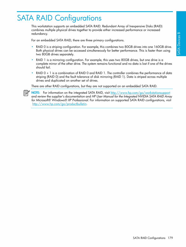
SATA
Dev
ices
B
SATA RAID ConfigurationsThis workstation supports an embedded SATA RAID. Redundant Array of Inexpensive Disks (RAID) combines multiple physical drives together to provide either increased performance or increased redundancy.
For an embedded SATA RAID, there are three primary configurations.
• RAID 0 is a striping configuration. For example, this combines two 80GB drives into one 160GB drive. Both physical drives can be accessed simultaneously for better performance. This is faster than using two 80GB drives separately.
• RAID 1 is a mirroring configuration. For example, this uses two 80GB drives, but one drive is a complete mirror of the other drive. The system remains functional and no data is lost if one of the drives should fail.
• RAID 0 + 1 is a combination of RAID 0 and RAID 1. The controller combines the performance of data striping (RAID 0) and the fault tolerance of disk mirroring (RAID 1). Data is striped across multiple drives and duplicated on another set of drives.
There are other RAID configurations, but they are not supported on an embedded SATA RAID.
NOTE: For information on the integrated SATA RAID, visit http://www.hp.com/go/workstationsupport and review the supplier’s documentation and HP User Manual for the Integrated NVIDIA SATA RAID Array for Microsoft® Windows® XP Professional. For information on supported SATA RAID configurations, visit http://www.hp.com/go/productbulletin.
SATA RAID Configurations 179

SATA Devices180

Con
nect
or P
ins
C
C Connector Pins
This appendix provides pin information for your system:
• “Enhanced Keyboard” on page 182
• “Mouse” on page 182
• “Ethernet RJ-45” on page 182
• “Serial Interface” on page 183
• “USB” on page 183
• “IEEE 1394” on page 183
• “Microphone” on page 184
• “Headphone” on page 184
• “Line-in Audio” on page 184
• “Line-out Audio” on page 184
• “Ultra SCSI” on page 185
• “SATA” on page 186
• “Monitor (DVI)” on page 187
• “Monitor (VGA)” on page 187
• “ATA/ATAPI (IDE) Standard Drive Cable” on page 188
• “24-Pin Power (Main)” on page 189
• “8-Pin Power (for Processors)” on page 189
• “6-Pin Power (Auxiliary PCI Express)” on page 190
181

Enhanced Keyboard
Mouse
Ethernet RJ-45
Keyboard Connector Pin Signal
123
DataUnusedGround
456
+5 VDCClockUnused
Mouse Connector Pin Signal
123
DataUnusedGround
456
+5 VDCClockUnused
Ethernet Connector Pin Signal
1234
(+) Transmit Data(-) Transmit Data(+) Receive DataUnused
5678
Unused(-) Receive DataUnusedUnused
Connector Pins182

Con
nect
or P
ins
C
Serial Interface
USB
IEEE 1394
Serial Connector Pin Signal
123
Carrier DetectReceive DataTransmit Data
456
Data Terminal ReadySignal GroundData Set Ready
789
Request to SendClear to SendRing Indicator
USB Connector Pin Signal
1234
+5 VDC- Data+ DataGround
IEEE 1394 Connector Pin Signal
1 power
2 gnd
3 tpb-
4 tpb+
5 tpa-
6 tpa+
Serial Interface 183

Microphone
Headphone
Line-in Audio
Line-out Audio
Microphone Connector (1/8 inch) Pin Signal
1 (Tip)2 (Ring)3 (Shield)
AudioPowerGround
Headphone Connector (1/8 inch) Pin Signal
1 (Tip)2 (Ring)3 (Shield)
Audio_LeftAudio_RightGround
Line-in Audio Connector (1/8 inch) Pin Signal
1 (Tip)2 (Ring)3 (Shield)
Audio_In_LeftAudio_In_RightGround
Line-out Audio Connector (1/8 inch) Pin Signal
1 (Tip)2 (Ring)3 (Shield)
Audio_Out_LeftAudio_Out_RightGround
Connector Pins184

Con
nect
or P
ins
C
Ultra SCSIUltra SCSI connector
Pin Signal Pin Signal
1 +DB12 35 -DB12
2 +DB13 36 -DB13
3 +DB14 37 -DB14
4 +DB15 38 -DB15
5 +DPB1 39 -DPB1
6 +DB0 40 -DB0
7 +DB1 41 -DB1
8 +DB2 42 -DB2
9 +DB3 43 -DB3
10 +DB4 44 -DB4
11 +DB5 45 -DB5
12 +DB6 46 -DB6
13 +DB7 47 -DB7
14 +DPB 48 -DPB
15 GND 49 GND
16 DIFFSENSE 50 GND
17 TERMPWR 51 TERMPWR
18 TERMPWR 52 TERMPWR
19 RESERVE 53 RESERVE
20 GND 54 GND
21 +ATN 55 -ATN
22 GND 56 GND
23 +BSY 57 -BSY
24 +ACK 58 -ACK
25 +RST 59 -RST
26 +MSG 60 -MSG
27 +SEL 61 -SEL
28 +C/D 62 -C/D
29 +REQ 63 -REQ
30 +I/O 64 -I/O
31 +DB8 65 -DB8
32 +DB9 66 -DB9
33 +DB10 67 -DB10
34 +DB11 68 -DB11
Ultra SCSI 185

SATASATA Connector
Pin Signal Pin Signal Pin Signal
Data Cable Power Cable Power Cable
S-1 Ground P-1 3.3-V power P-8 5-V power
S-2* A+ P-2 3.3-V power P-9 5-V power
S-3* A- P-3 3.3-V power P-10 Ground
S-4 Ground P-4 Ground P-11 Reserved
S-5** B- P-5 Ground P-12 Ground
S-6** B+ P-6 Ground P-13 12-V power
S-7 Ground P-7 5-V power P-14 12-V power
* S2 and S3 differential signal pair**S5 and S6 differential signal pair
P-15 12-V power
Connector Pins186

Con
nect
or P
ins
C
Monitor (VGA)NOTE: Monitor connectors can vary depending on your configuration.
Monitor (DVI)NOTE: Monitor connectors can vary depending on your configuration.
VGA Connector
Pin Signal Pin Signal Pin Signal
123
Red AnalogGreen AnalogBlue Analog
678
GroundGroundGround
111213
Monitor IDDDC Serial DataHorizontal Sync
45
Monitor IDGround
910
+5V DCGround
1415
Vertical SyncDDC Serial Clock
DVI Connector
Pin Signal Pin Signal
1 T.M.D.S DATA 2- 16 HOT PLUG DETECT
2 T.M.D.S DATA 2+ 17 T.M.D.S DATA 0-
3 T.M.D.S DATA 2/4 SHIELD 18 T.M.D.S DATA 0+
4 T.M.D.S DATA 4- 19 T.M.D.S DATA 0/5 SHIELD
5 T.M.D.S DATA 4+ 2 0 T.M.D.S DATA 5-
6 DDC CLOCK 21 T.M.D.S DATA 5+
7 DDC DATA 22 T.M.D.S CLOCK SHIELD
8 ANALOG VERT. SYNC 23 T.M.D.S CLOCK+
9 T.M.D.S DATA 1- 24 T.M.D.S CLOCK-
10 T.M.D.S DATA 1+ C1 ANALOG RED
11 T.M.D.S DATA 1/3 SHIELD C2 ANALOG GREEN
12 T.M.D.S DATA 3- C3 ANALOG BLUE
Monitor (VGA) 187

ATA/ATAPI (IDE) Standard Drive Cable
13 T.M.D.S DATA 3+ C4 ANALOG HORZ SYNC
14 +5V POWER C5 ANALOG GROUND
15 GND
ATA/ATAPI (IDE) Connector
Pin Signal Pin Signal Pin Signal
12345
ResetGroundDD7DD8DD6
1516171819
DD1DD14DD0DD15Ground
2930313233
DMAKGroundINTRQIOCS16DA1
678910
DD9DD5DD10DD4DD11
2021222324
(Key)DMARQGroundDIOWGround
3435363738
PDIAG (cable detect)DA0DA2CS1FXCS3FX
11121314
DD3DD12DD2DD13
25262728
DIORGroundIORDYCSEL
3940
DASPGround
Connector Pins188
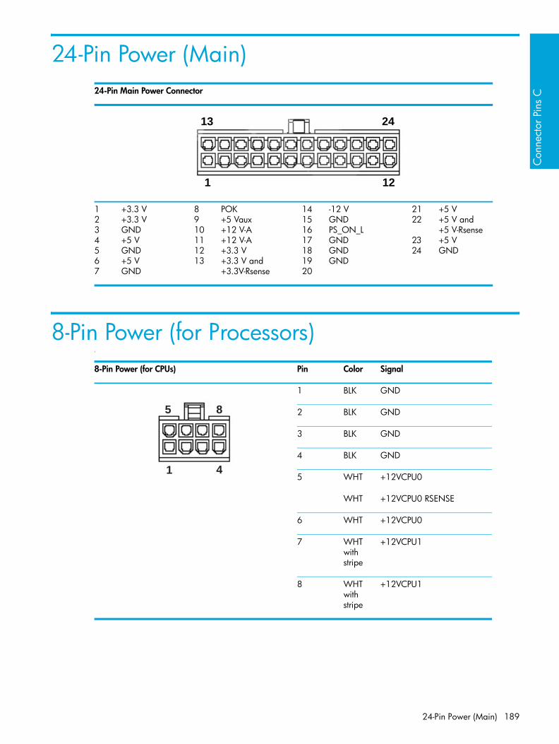
Con
nect
or P
ins
C
24-Pin Power (Main)
8-Pin Power (for Processors)1
24-Pin Main Power Connector
1234567
+3.3 V+3.3 VGND+5 VGND+5 VGND
8910111213
POK+5 Vaux+12 V-A+12 V-A+3.3 V+3.3 V and +3.3V-Rsense
14151617181920
-12 VGNDPS_ON_LGNDGNDGND
2122
2324
+5 V+5 V and+5 V-Rsense+5 VGND
1 12
13 24
8-Pin Power (for CPUs) Pin Color Signal
1 BLK GND
2 BLK GND
3 BLK GND
4 BLK GND
5 WHT +12VCPU0
WHT +12VCPU0 RSENSE
6 WHT +12VCPU0
7 WHT with stripe
+12VCPU1
8 WHT with stripe
+12VCPU1
5 8
41
24-Pin Power (Main) 189

6-Pin Power (Auxiliary PCI Express)NOTE: The 6-pin power (auxiliary PCI Express) is only required with high-powered graphics cards.
6-Pin Power (Auxiliary PCI Express) Pin Color Signal
1 YEL +12V-C
2 YEL +12V-C
3 YEL +12V-C
4 BLK GND
5 BLK GND
6 BLK GND
4 6
31
Connector Pins190

Syste
m B
oard
Des
igna
tors
D
D System Board Designators
This appendix lists the system board designators for this system.
Table D-39 System Board Designators
Designator Silkscreen Component
MH1-8, MH10-11, MH14 N/A Mounting holes
E14 N/A Boot block header/jumper
E49 PSWD Clear password header/jumper
J20 SLOT2 PCI PCI slot
J23 SLOT6 PCI-X 133MHz PCI slot
J21 SLOT4 PCI-X 100MHz PCI slot
J22 SLOT5 PCI-X 100MHz PCI slot
J37 SCSI1 Primary SCSI connector
J38 SCSI2 Secondary SCSI connector
J41 SLOT1 PCI-E X16 PCI Express x16 slot for graphics
J68 N/A Stacked keyboard/mouse connector
J9 N/A Stacked RJ45/Dual USB
J82 N/A Double stacked USB
J8 N/A IEEE 1394 connector-rear
J83 AUD Triple stacked audio jack
P1 P1 Power supply connector (24 pin)
J42 SLOT3 PCI-E X16 PCI Express x16 slot for second graphics or PCI Express card
J109 J109 IEEE 1394 front panel connector
P3 P3 Second power supply connector
P10 FDD Diskette drive connector
P101 SECURITY Security board connector
P7 CD CD analog audio connector
P11 AUX Auxiliary audio connector
191

P20 N/A Primary IDE connector
P23 FRNT AUD Front panel audio header
P24 FRNT USB Front panel USB header
P29 HD-LED HDD LED connector
P50 SATA1 port 2 Serial ATA (SATA) port 2 connector
P51 SATA1 port 3 Serial ATA (SATA) port 3 connector
P52 SATA0 Serial ATA (SATA) port 0 and 1 connector
J86 FRNT-P Front panel connector
P53 P53 Serial port
P70 CPU1FAN Primary CPU fan header
P71 CPU2FAN Secondary CPU fan header
P8 RCHFAN2 Primary chassis fan header
P9 FCHFAN1 Secondary chassis fan header
SW50 CLR CMOS Clear CMOS switch/push button
XBT XBT1 Battery retainer
XMM1 DIMM1A Memory slot
XMM2 DIMM1B Memory slot
XMM3 DIMM2A Memory slot
XMM4 DIMM2B Memory slot
XMM5 DIMM3A Memory slot
XMM6 DIMM3B Memory slot
XMM7 DIMM4A Memory slot
XMM8 DIMM4B Memory slot
XU1 CPU0 Primary processor socket
XU2 CPU1 Secondary processor socket
U15 U15 ROM socket
U150 U150 SCSI controller option ROM
Table D-39 System Board Designators
Designator Silkscreen Component
System Board Designators192

Pow
er C
ord
Set R
equi
rem
ents
E
E Power Cord Set Requirements
The power cord set (flexible cord or wall plug) received with this product meets the requirements for use in the country where you purchased the equipment.
If you must obtain a power cord for a different country, you should purchase a power cord that is approved for use in that country.
The power cord must be rated for the product and for the voltage and current marked on the product’s electrical ratings label. The voltage and current rating of the cord should be greater than the voltage and current rating marked on the product. In addition, the diameter of the wire must be a minimum of 0.75mm2 or 18 AWG, and the length of the cord must be between 6 feet (1.8 m) and 12 feet (3.6 m). If you have questions about the type of power cord to use, contact the HP authorized service provider.
A power cord should be routed so that it is not likely to be walked on or pinched by items placed on it or against it. Particular attention should be paid to the plug, electrical outlet, and the point where the cord exits from the product.
193

Power Cord Set Requirements194

Rout
ine
Car
e F
F Routine Care
This appendix contains the additional information for caring for your system:
• “General Cleaning Safety Precautions” on page 196
• “Maximizing the Airflow” on page 197
• “Cleaning the Workstation Case” on page 198
• “Cleaning the Keyboard” on page 199
• “Cleaning the Monitor” on page 200
• “Cleaning the Mouse” on page 201
195

General Cleaning Safety Precautions• Never use solvents or flammable solutions to clean the workstation.
• Never immerse any parts in water or cleaning solutions; apply any liquids to a clean cloth and then use the cloth on the component.
• Always unplug the workstation when cleaning with liquids or damp cloths.
• Always unplug the workstation before cleaning the keyboard, mouse, or air vents.
• Disconnect the keyboard before cleaning it.
• Wear safety glasses equipped with side shields when cleaning the keyboard.
Routine Care196

Rout
ine
Car
e F
Maximizing the AirflowKeep your workstation in an area where the airflow to the front and rear of the system is not obstructed.
• If possible, keep the unit off of surfaces where dust can gather.
• Keep the back of the unit at least 6 inches away from a wall or other obstruction.
• Keep the front of the unit clear of any obstruction that keeps air from entering the front of the system.
• Remove any dust on the front panel (vent area) and the rear fans with a small vacuum, compressed air, or dust rag.
Maximizing the Airflow 197

Cleaning the Workstation CaseFollow previously stated safety precautions before cleaning the workstation.
To clean the workstation case:
• To remove light stains or dirt, use plain water with a clean, lint-free cloth or swab.
• For stronger stains, use a mild dish-washing liquid diluted with water. Rinse well by wiping it with a cloth or swab dampened with clear water.
• For stubborn stains, use isopropyl (rubbing) alcohol. No rinsing is needed as the alcohol will evaporate quickly and not leave a residue.
• After cleaning, always wipe the unit with a clean, lint-free cloth.
• Occasionally clean the air vents on the workstation. Lint and other foreign matter can block the vents and limit the airflow.
Routine Care198

Rout
ine
Car
e F
Cleaning the KeyboardFollow all safety precautions stated earlier before cleaning the keyboard.
CAUTION: Use safety glasses equipped with side shields before attempting to clean debris from under the keys.
• Visible debris underneath or between the keys can be removed by vacuuming or shaking.
• Canned, pressurized air can be used to clean debris from under the keys. Caution should be used as too much air pressure can dislodge lubricants applied under the wide keys.
• If you remove a key, use a specially designed key puller to prevent damage to the keys. This tool is available through many electronic supply outlets.
CAUTION: Never remove a wide leveled key (like the space bar) from the keyboard. If these keys are improperly removed or installed, the keyboard might not function properly.
• Cleaning under a key can be done with a swab moistened with isopropyl alcohol and squeezed out. Be careful not to wipe away lubricants necessary for proper key functions. Use tweezers to remove any fibers or dirt in confined areas. Allow the parts to air dry before reassembly.
Cleaning the Keyboard 199

Cleaning the MonitorFollow all safety precautions stated earlier before cleaning the monitor.
To clean the monitor, wipe the monitor screen with a clean cloth moistened with water or with a towelette designed for cleaning monitors. Do not use sprays or aerosols directly on the screen; the liquid might seep into the housing and damage a component. Never use solvents or flammable liquids on the monitor.
Routine Care200

Rout
ine
Car
e F
Cleaning the MouseFollow all safety precautions stated earlier before cleaning the mouse.
To clean the mouse:
• Clean the mouse ball by first removing the retaining plate and the ball from the housing.
• Pull out any debris from the ball socket and wipe the ball with a clean, dry cloth before reassembly.
Cleaning the Mouse 201

Routine Care202
Add
ition
al P
assw
ord
Secu
rity
and
Rese
tting
CM
OS
G
G Additional Password Security and Resetting CMOSThis workstation supports security password features, which can be established through the Computer Setup Security menu. These features are:
• setup password
• power-on password
When both passwords are set, the setup password can also be used in place of the power-on password as an override to log in to the workstation. This is a useful feature for a network administrator.
If you forget the password for the computer, there are two methods for clearing that password so you can gain access to the information on the workstation.
• resetting the password jumper
• using the Clear CMOS button
CAUTION: Pushing the CMOS button resets CMOS values to factory defaults and erases any customized information including passwords, asset numbers, and special settings. It is important to back up the workstation CMOS settings before resetting them in case they are needed later. To back up the CMOS settings, use Computer Setup and run the Save to Diskette option from the File menu.
203

Resetting the Password JumperTo disable the power-on or setup password features and clear the power-on and setup passwords:
1. Shut down the operating system and then turn off the workstation and any external devices. Disconnect the power cord of the workstation and any external devices from the power outlets.
WARNING! To reduce the risk of personal injury from electrical shock and hot surfaces, be sure to disconnect the power cord from the wall outlet and allow the internal system components to cool before touching.
CAUTION: When the workstation is plugged in, the power supply always has voltage applied to the system board even when the unit is turned off. Failure to disconnect the power cord can result in damage to the system.
CAUTION: Static electricity can damage the electronic components of the workstation or optional equipment. Before beginning these procedures, be sure that you are discharged of static electricity by briefly touching a grounded metal object.
2. Remove the access panel.
3. Locate the password header and jumper. The password header is E49.
NOTE: The password jumper is green so that it can be easily identified. For assistance locating the password jumper and other system board components, refer to “System Board” on page 80.
4. Remove the jumper. Place the jumper on either pin 1 or 2 (not both).
5. Replace the access panel.
6. Plug in the workstation and turn on the power. Allow the operating system to start. This clears the current passwords and disables the password features.
7. To establish new passwords, repeat steps 1 through 3, replace the password jumper on both pins 1 and 2, then repeat steps 5 through 7. Establish the new passwords in Computer Setup.
Additional Password Security and Resetting CMOS204

Add
ition
al P
assw
ord
Secu
rity
and
Rese
tting
CM
OS
G
Clearing and Resetting the CMOSThe CMOS of the workstation stores password information and information about the workstation configuration. This section describes the steps to successfully clear and reset the CMOS.Using Computer Setup to Reset CMOSTo reset CMOS using Computer Setup, access the Computer Setup Utilities menu. When the Computer Setup message appears in the lower-right corner of the screen, press the F10 key. Press Enter to bypass the title screen, if necessary.
NOTE: If you do not press the F10 key while the message is displayed, the workstation must be restarted to access the utility.
From the Computer Setup menu, select File > Set Defaults and Exit. This restores the soft settings that include boot sequence order and other factory settings. It does not, however, force hardware rediscovery.
NOTE: The workstation passwords and any special configurations along with the system date and time will have to be reset.
Clearing and Resetting the CMOS 205

Using the CMOS ButtonCAUTION: Pushing the CMOS button resets CMOS values to factory defaults and erases any customized information including passwords, asset numbers, and special settings. It is important to back up the workstation CMOS settings before resetting them in case they are needed later. To back up the CMOS settings, use Computer Setup and run the Save to Diskette option from the File menu.
1. Shut down the operating system and then turn off the workstation and any external devices. Disconnect the power cord of the workstation and any external devices from the power outlets.
WARNING! To reduce the risk of personal injury from electrical shock and hot surfaces, be sure to disconnect the power cord from the wall outlet and allow the internal system components to cool before touching.
CAUTION: When the workstation is plugged in, the power supply always has voltage applied to the system board even when the unit is turned off. Failure to disconnect the power cord can result in damage to the system.
CAUTION: Static electricity can damage the electronic components of the workstation or optional equipment. Before beginning these procedures, be sure that you are discharged of static electricity by briefly touching a grounded metal object.
2. Remove the access panel.
3. Locate, press, and hold the CMOS button in for five seconds.
NOTE: For assistance locating the CMOS button and other system board components, refer to “System Board” on page 80.
4. Replace the access panel.
5. Plug in the workstation power and turn the power back on.
NOTE: The workstation passwords and any special configurations along with the system date and time will have to be reset.
Additional Password Security and Resetting CMOS206

Qui
ck T
roub
lesh
ootin
g Fl
ows
H
H Quick Troubleshooting Flows
This appendix presents some quick troubleshooting flowcharts for some common issues.
NOTE: The flowcharts presented here are for general troubleshooting purposes only and they might not apply to your specific workstation.
• “Initial Troubleshooting” on page 208
• “No Power” on page 209
• “No Video” on page 212
• “Error Messages” on page 215
• “No OS Loading” on page 218
• “No OS Loading from Hard Drive” on page 219
• “No OS Loading from Diskette Drive” on page 222
• “No OS Loading from CD-ROM Drive” on page 223
• “No OS Loading from Network” on page 224
• “Non-functioning Device” on page 225
207

Initial Troubleshooting
Quick Troubleshooting Flows208

Qui
ck T
roub
lesh
ootin
g Fl
ows
H
No Power
No Power, Part 1
No Power 209
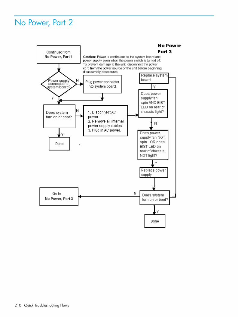
No Power, Part 2
Quick Troubleshooting Flows210
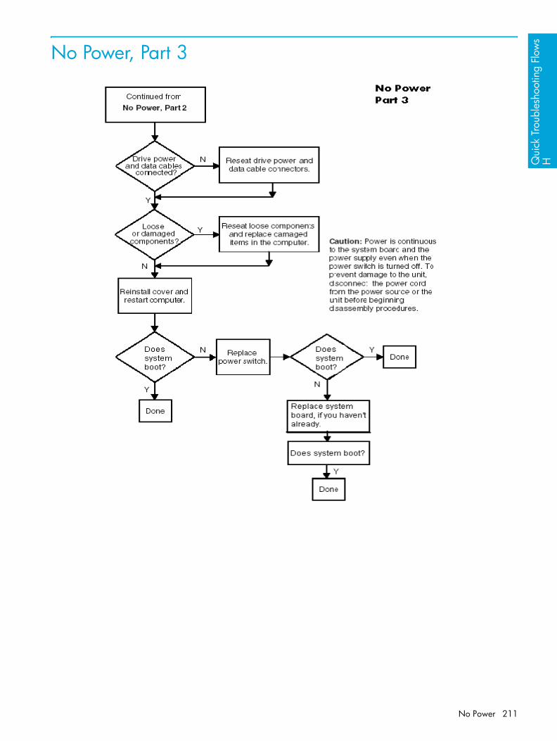
Qui
ck T
roub
lesh
ootin
g Fl
ows
H
No Power, Part 3
No Power 211

No Video
No Video, Part 1
Quick Troubleshooting Flows212
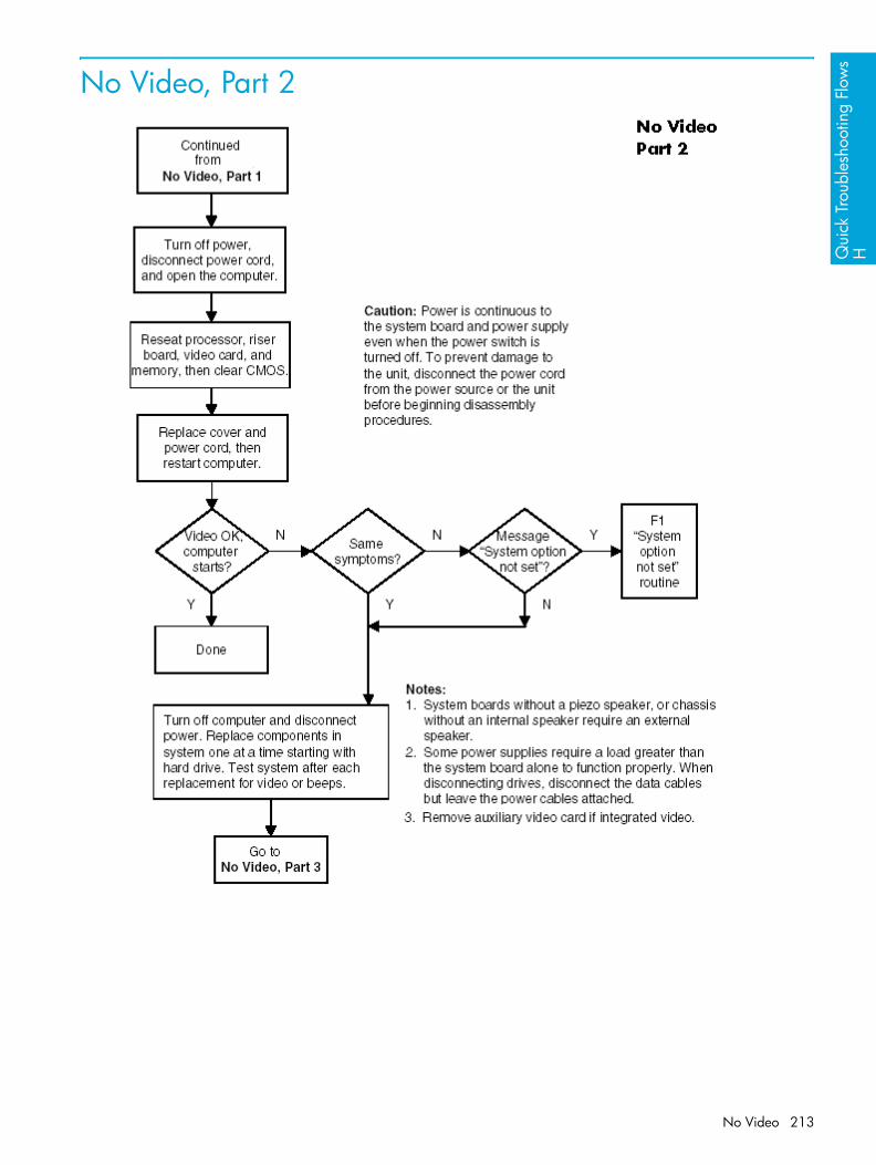
Qui
ck T
roub
lesh
ootin
g Fl
ows
H
No Video, Part 2
No Video 213

No Video, Part 3
Quick Troubleshooting Flows214

Qui
ck T
roub
lesh
ootin
g Fl
ows
H
Error Messages
Error Messages, Part 1
Error Messages 215
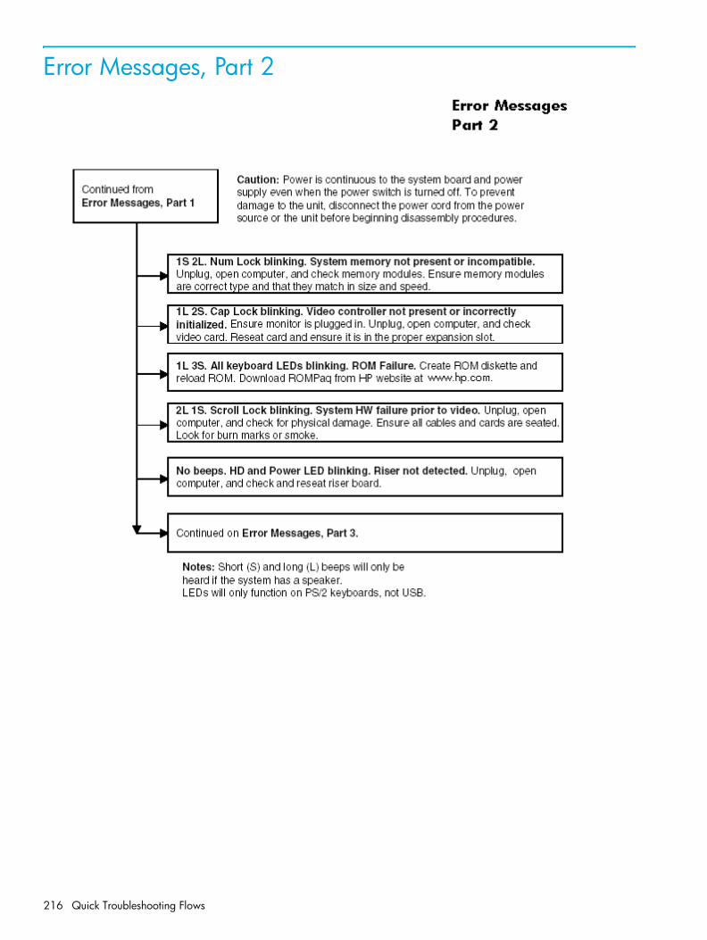
Error Messages, Part 2
Quick Troubleshooting Flows216

Qui
ck T
roub
lesh
ootin
g Fl
ows
H
Error Messages, Part 3
Error Messages 217

No OS Loading
Quick Troubleshooting Flows218

Qui
ck T
roub
lesh
ootin
g Fl
ows
H
No OS Loading from Hard Drive
No OS Loading from Hard Drive, Part 1
No OS Loading from Hard Drive 219

No OS Loading from Hard Drive, Part 2
Quick Troubleshooting Flows220

Qui
ck T
roub
lesh
ootin
g Fl
ows
H
No OS Loading from Hard Drive, Part 3
No OS Loading from Hard Drive 221

No OS Loading from Diskette Drive
Quick Troubleshooting Flows222

Qui
ck T
roub
lesh
ootin
g Fl
ows
H
No OS Loading from CD-ROM Drive
No OS Loading from CD-ROM Drive 223

No OS Loading from Network
Quick Troubleshooting Flows224

Qui
ck T
roub
lesh
ootin
g Fl
ows
H
Non-functioning Device
Non-functioning Device 225

Quick Troubleshooting Flows226

Inde
x
Index
24-pin power connector pin assignments 189
6-pin PCI Express connector pin assignments 190
8-pin power for processors connector pin assignments 189
Aaccess panel, installing and
removing 86airflow 28asset tracking and security 64
Bbattery
disposal 78handling 78installing and removing 105real-time clock 142
bezel blanks, installing and removing 87
BIST LEDlocation 20
blank screen 149block diagram 81boot options 51
Ccable
proper handling 77cable lock
Kensington 70provision 70
cable lock slotlocation 20
cablespower 106
cables and connectors 77cautions
adding devices 33batteries 78cable routing 172cables 77, 79cooling fan 79installation 33keyboard cleaning 199keyboard keys 199
CD-ROM driveSee optical drive
chain termination, SCSI 172changing password 67
cleaningkeyboard 199monitor 200mouse 201
clearing password 69cloning tools, software 55CMOS
button 206clearing and resetting 205
componentsexploded view 18front panel 19rear panel 20
computer pauses 142Computer Setup (F10)
Advanced functions 51File functions 47menu 47overview 44Security functions 50Storage functions 48using 46utilities 46
connectorsfront panel 19
customizing software 55
Ddate and time display 142deleting password 68deployment tools, software 55desktop management 54device
onboard 52device configuration 48diagnostic
light codes 140diagnostic tool for hard drives 71DIMMs, installing and removing 94disassembly order 83disk, cloning 55diskette drive
installing and removing 109troubleshooting 146
Documentation 15Documentation Library CD
contents 14, 15using 15
driveDrive Protection System (DPS) 71protecting 71
Drive Protection System 71DVD-ROM drive
See optical drive
EECC Fault Prediction and Prefailure
Warranty 71Energy Star 32entering
power-on password 66setup password 67
environmental specification 30ESD (electrostatic discharge)
materials and equipment 76preventing damage 75
exploded view 18
Ffault notification and recovery 71finding additional information 14front bezel, installing and removing
87front fan, installing and removing
103front panel components 19front panel I/O device assembly,
installing and removing 89front panel, troubleshooting 155
Ggraphics adapter
location 20graphics card
power specifications 31grounding methods 76
Hhandling the workstation 77hard drive
activity light 19diagnostic tool 71installing and removing 111proper handling 77SCSI drives 172troubleshooting 148
hardwareremoval and replacement 82troubleshooting 156
headphonejack location 19
Index 227

heatsink, installing and removing 116
hood coverinstallation and removal 86
HP Client Management Solutions 54
IIDE connector pin assignments 188IEEE-1394
front panel location 19rear panel location 20
informationsystem 47
initial configuration 55installing
access panel 86battery 105bezel blanks 87DIMMs 94diskette drive 109front bezel 87front fan 103front panel I/O device assembly
89hard drive 111heatsink 116hood cover 86Kensington cable lock 84memory 94optical drive 107PCI card support 98PCI Express 99power button assembly 90power supply 91processor 127SATA 115security lock 84speaker assembly 90system board 129system fan 93
internal computer temperature 71
Jjumpers
resetting passwords 204
KKensington cable lock 70
installation and removal 84overview 70purpose 65
keyboardcleaning 199connector pin assignments 182delimiter characters 68PS/2 connector location 20troubleshooting 154
keyslocation 20
LLED
color definitions 134lifting the workstation 77line-in audio
connector location 20line-out audio
connector location 20
Mmemory
guidelines 94installing and removing 94troubleshooting 160
memory errors 71microphone
connector location 19, 20Microsoft Windows XP Professional
operating system 34monitor
blank screen 149blurry video 150cleaning 200connector pin assignments 187dim characters 150
mother board 129mouse
cleaning 201connector pin assignments 182PS/2 connector location 20
Nnetwork connector location 20non-correctable memory errors 71
Ooperating system
Microsoft Windows XP Professional 34
optical driveactivity light location 19bays 19eject button 19installing and removing 107location 19
Ppadlock
location 20padlock loop, purpose 65password
additional information 203changing 67clearing 69deleting 68
power-on 50, 66, 165resetting jumpers 204security 65setup 50, 65, 67
PCI card support, installing and removing 98
PCI Expresscompatibility matrix 99overview 99
PCI Express, installing and removing 99
PCI slot power specifications 31PCI slots
identification 97POST error messages 165power
BIST LED 20button 19consumption and cooling 27dual-state button 62light 19resetting power supply 29
power button, installing and removing 90
power cordlocation 20
power supplycables 106installing and removing 91routing cables 106surge tolerance 71surge-tolerant 71
power-on password 165entering 66establishing 66purpose 64setting 66
pre-disassembly procedures 79prefailure memory warranty 71preinstalled software image 55problems
audio 151CD-ROM and DVD 162diskette 146display 149front panel 155hard drive 148installing hardware 156keyboard 154memory 160network 158optical drives 162power supply 144printer 153
processor, installing and removing 127
productoverview 17specifications 22
Index228

Inde
x
protectinghard drive 71
Rrear panel components 20recovery, software 55remote setup 56Remote System Installation 56removable media boot 49removal and replacement 82removing
access panel 86battery 105bezel blanks 87DIMMs 94diskette drive 109front bezel 87front fan 103front panel I/O device assembly
89hard drive 111heatsink 116hood cover 86Kensington cable lock 84memory 94optical drive 107PCI card support 98PCI Express 99power button assembly 90power supply 91processor 127SATA 115security lock 84speaker 90system board 129system fan 93universal clamp lock 85
SSafety 10safety precautions, cleaning 196SATA
RAID 179SATA drives
guidelines 178SATA, installing and removing 115screws 77SCSI drives 172
chain termination 172guidelines 172SMART 174
SCSISelect utility 173security
features overview 64features, table 64
security lock installation and removal 84
serial connector location 20
serial connector pin assignments 183
serial number location 21setting
power-on password 66setup password 65, 67
setupinitial 55
setup passwordentering 67establishing 65purpose 64setting 65
side access panel sensoroverview 69setting protection level 69
SMART 174software
configuration and deployment 55
customizing 55Drive Protection System 71Fault Notification and Recovery
71management and updating 57managing 57recovery 55Remote Management Setup 56Remote System Installation 56SCSISelect utility 173service requirements 77updating 57
speaker, installing and removing 90
static electricity 75generating 75grounding methods 75, 76preventing damage 75
surge-tolerant power supply 71system
diagnostics and troubleshooting 131
management 43overview 17setting time and date 47specifications 22
system boardblock diagram 81installing and removing 129
system fan, installing and removing 93
Ttemperature, internal computer 71thermal sensor 71tool requirements 77troubleshooting
audio problems 151
CD-ROM and DVD problems 162
diskette problems 146front panel problems 155hard drive problems 148hardware installation problems
156Internet access problems 163keyboard problems 154memory problems 160minor problems 142network problems 158preliminary checklist 131printer problems 153processor problems 161scenarios and solutions 142video problems 149
UUltra ATA Integrity Monitoring 71universal chassis clamp
location 20USB
connector pin assignments 183front panel location 19
USB portsrear panel location 20
WWake-on-LAN feature 158warnings
battery 78lifting and moving 74
Index 229

Index230