• p· I'J'TC .. Innovation and Technology Transfer Centre University of Miskolc XXIV. microCAD International Scientific Conference 18·20 March 2010 F szekci6: Aramlas- as hotechnika Section F: Fluid and Heat Engineering
Transcript
• p·I'J'TC .. Innovation and Technology Transfer Centre University of Miskolc
XXIV. microCAD International Scientific Conference
A proJakt a NemzaU KutatiiSI as TechnolOgial Hlvatal tamogatasaval valosult meg.
Kiadja a Misko/ci Egyetem lnnovacias es Techno/agia Transzjer Centruma KiadasertjeJelifs: Dr. Dobraka Miha/y rektorhelyettes Szerkeszto: Dr. Bilifa/vi Peter osztalyvezeto Nyomda: !vfE Sokszorosita Uzeme Uzemvezetif: Kovacs Tibor Nyomdaszam: !vfE. Tu-J38/201 O. ISBN 978-963-661-925-1 6 ISBN 978-963-661-910-7
TEMPERA TURE FIELD VISUALIZA nON AROUND A HEATED CIRCULAR CYLINDER BY SCHLIEREN TECHNIQUE
Peter Bellc/, S zilard SzabO] I PhD student, 2 Professor
Department of Fluid and Heal Engineering, University of Miskolc, Hungary
I. INTRODUCTION
Prismatic bodies placed in a flow often have different temperature compared to that of the surroundings such as electrical transmission lines, cartridge heaters, pipes of heat exchangers, factory chimneys and so on. Tbe structure of tbe flow, developing around prismatic bodies bas been already examined for a long time. Tbe evolving Karman vortex street was and is examined by numerous researchers both experimentally and numerically. Schlieren measurement technique has also been investigated by many researchers (1-3]. For example, sucb a Scblieren system can be used for visualization of shockwave in a supersonic tunnel [4-7]. The system is basically adapted for 2D measurements; there are many problems with 3D measurements [4]. The experimental tests were carried out at low Reynolds numbers (Re<200), thus the flow field was approximately two dimensional (same flow in every normal plans of a heated circular cylinder).Tbe method has also been used for general visualization ofheat transport processes [4]. In this work the adaptability of a Schlieren system is investigated, which should be ultimately applicable in a wind-tunnel in order to investigate forced convection flows. An electrically heated circular cylinder was placed perpendicular to the flow in a wind tunnel. The first objective of this work is to determine the structure of the instantaneous temperature field. The results show, that the system will be good for quantitative measurements. Image processing will be the next important part of this project.
2. PRINCIPLE OF SCHLIEREN MEASUREMENT TECHNIQUE
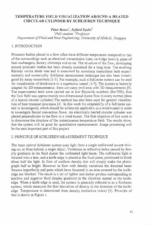
The basic optical Schlieren system uses light from a single collimated source shining on, or from behind, a target object. Variations in refractive index caused by density gradients in the fluid distort the collimated Iigbt beam. The collimated light is focused with a lens, and a knife-edge is placed at the focal point, positioned to block about half tbe light. In flow of uniform density this will simply make the photograph half as bright. However in flow with density var iations the distorted beam focuses imperfectly and parts which have focussed in an area covered by the knifeedge are blocked. The result is a set of lighter and darker patches corresponding to positive and negative fluid density gradients in the direction normal to the knifeedge. When a knife-edge is used, the system is generally referred to as a Schlieren system, which measures the first derivative of density in the direction of the knifeedge. Temperature is determined from density (refractive index) [4]. Principle of that is shown in Figure 1.
61
Point ScreenLen~1 Lens
"'"~~~ ~~ I ZO-model Schlieren
(unheated cylinder) knife edge t Flow direction
Point
Schlieren20-model
knife edge (heated cylinder)
Flow direction
Figure 1_ Measurement setup of a simple two-lens Schlieren system
3. EXPERIENCES OF Z-TYPE SCHLIEREN SYSTEM
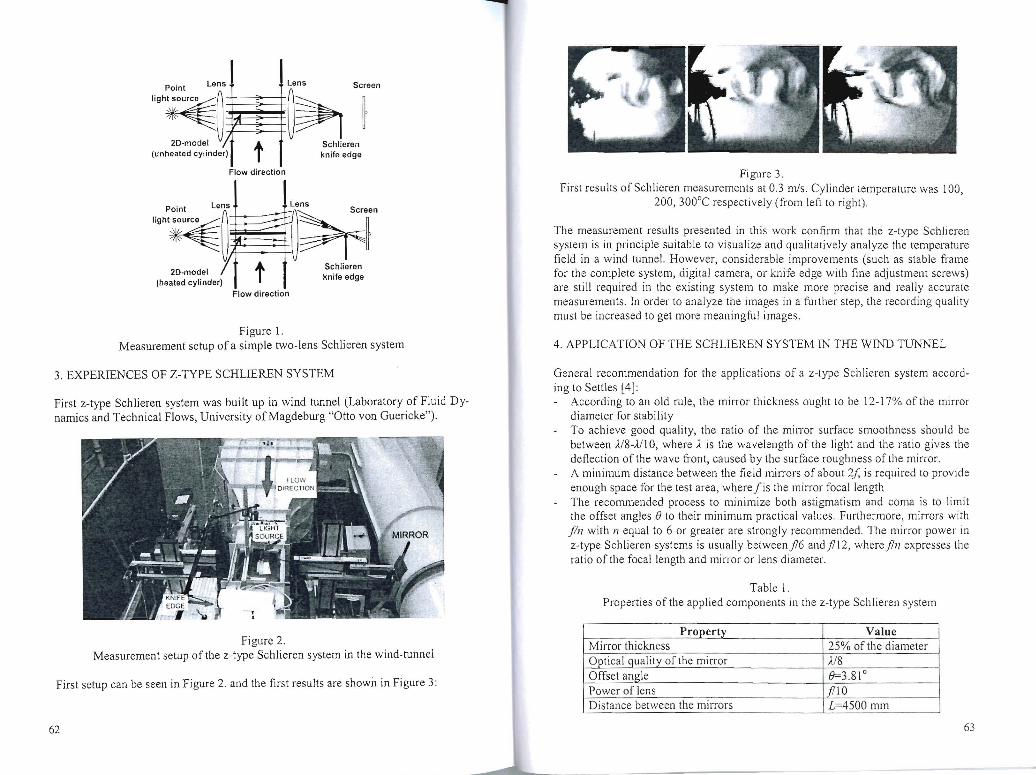
First z-type Schlieren system was built up in wind tunnel (Laboratory of Fluid Dynamics and Technical Flows, University of Magdeburg "Otto von Guericke").
Figure 2. Measurement setup oftbe z-type Schlieren system in the wind-tunnel
First setup can be seen in Figure 2. and the first results are shown in Figure 3:
Figure 3. First results of Schlieren measurements at OJ m/s. Cylinder temperature was 100 ,
200, 300°C respectively (from left to right).
The measurement results presented in this work confirm that the z-type Schlieren system is in principle suitable to visuali ze and quali tatively analyze th e temperature field in a wind tunnel. However, considerable improvements (such as stable frame for the complete system, digital camera, or knife edge wi th fine adjustment screws) are sti ll required in the exist ing system to make more precise and really accurate measurements. In order to analyze the images in a furt her step, the recording quality must be increased to get more meaningful images.
4. APPLICATION OF THE SCHLIEREN SYS TEM IN THE WIND TUNNEL
General recommendation for the applications of a z-type Schlieren system according to Settles [4]:
According to an old rule, the milTor thickness ought to be 12-1 7% of the mirror diameter for stability To achieve good quality, the ratio of the mirror surface smoothness should be between JJ8-m 0, where Ais the wavelength of the light and the ratio gives the deflection of the wave front, caused by the surface roughness of the mirror. A minimum distance between the field milTors of about 2f, is required to provide enough space for the test area, where lis the minor focal length The recommended process to minimize both astigmatism and coma is to limit the offset angles e to their minimum practical values. Furthermore, mirrors with pn with 11 equal to 6 or greater are strongly recommended . The mirror power in z-type Schlieren systems is usually betweenfl6 andfll2, where fin expresses the ratio of the focal length and min-or or lens diameter.
Table I . Propert ies of the applied components in the z-type Schlieren system
Property Vallie Mirror thickness 25% of the diameter Optical quality o[ the mirror JJ8 Offset angle 8=3.81° Power of lens fT lO Distance between the mirrors L=4500 mm
62 63
Heated cylinder
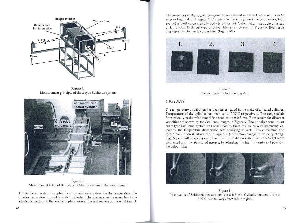
Figure 4. Measurement principle of the z-type Schlieren system
Figure 5. Measurement setup of the z-type Schlieren system in the wind-tunnel
The Schlieren system is applied here to qualitatively describe the temperature distribution in a flow around a heated cylinder. The measurement system has been adapted according to the available place around the test section of the wind tunnel.
64
.......,
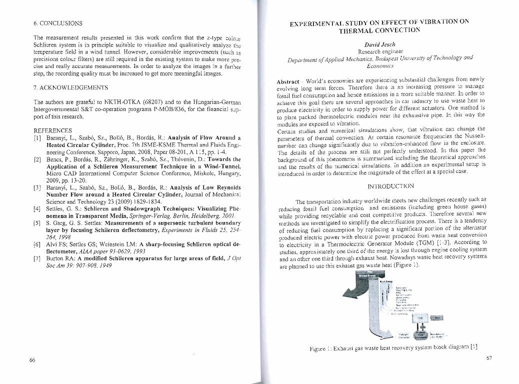
The properties of the applied components are detailed in Table 1. New setup can be seen in Figure 4. and Figure 5. Complete Schlieren System (min·ors, camera, light source) is built up on a stabile body (steel frame). Colour filter was applied instead of knife edge. Different type of colour filters can be seen in Figure 6. Best result was visualized by circle colour filter (Figure 611).
1. 2.
Figure 6. Colour filters for Schlieren system
5. RESULTS
The temperature distribution has been investigated in the wake of a heated cylinder. Temperature of the cylinder has been set to 300°C respectively. The range of air flow velocity in the wind tunnel has been set to O-OJ m/s. First results for different velocities are shown by the Schlieren images in Figure 9. The principle usability of our z-type Schlieren system was confirmed by these results, as with increasing velocities, the temperature distribution was changing as well. Free convection and forced convection is introduced in Figure 9. (convection change by velocity changing). Now it will be necessary to fine tune the Schlieren system, in order to get more contrasted and fine structured images, by adjusting the light intensity and position, the colour filter.
Figure 1. First results of Schlieren measurements at O-OJ m/s. Cylinder temperature was
300°C respectively (from lef1to right) .
65
6. CONCLUSIONS
The measurement results presented in this work confirm that the z-type colour Schlieren system is in principle suitable to visualize and qualitatively analyze the temperature field in a wind tunnel. However, considerable improvements (such as precisions colour filters) are still required in the existing system to make more precise and really accurate measurements. In order to analyze the images in a further step, the recording quality must be increased to get more meaningful images.
7. ACKNOWLEDGEMENTS
The authors are grateful to NKTH-OTKA (68207) and to the Hungarian-German Intergovernmental S&T co-operation programs P-MOB/836, for the financial support of this research.
REFERENCES [I] Baranyi, L., Szabo, Sz., Bolio, B., Bordas, R.: Analysis of Flow Around a
Heated Circular Cylinder, Proc. 7th JSME-KSME Thermal and Fluids Engineering Conference, Sapporo, Japan, 2008, Paper 08-20 I, AilS, pp. 1-4.
[2J Bencs, P., Bordas, R., Zahringer, K., Szabo, Sz. , Thevenin, D.: Towards the Application of a Schlieren Measurement Technique in a Wind-Tunnel, Micro CAD International Computer Science Conference, Miskolc, Hungary, 2009, pp. 13-20.
[3J Baranyi, L., Szabo, Sz., Bolio, B. , Bordas , R.: Analysis of Low Reynolds Number Flow around a Heated Circular Cylinder, Journal of Mechanical Science and Technology 23 (2009) 1829-1834.
[4J Settles, G . S.: Schlieren aDd Shadowgraph Techniques: Visualizing Phenomena in Transparent Media, Springer-Verlag, Berlin, Heidelberg, 2001 .
[5J S. Garg, G. S. Settles: Measurements of a supersonic turbulent boundary layer by focusing Schlieren deflectometry, Experiments in Fluids 25, 254-264, 1998
[6J Alvi FS; Settles GS; Weinstein LM: A sharp-focusing Schlieren optical deflectometer, AlAA paper 93-0629, 1993
[7J Burton RA: A modified Schlieren apparatus for large areas of field, J Opt Soc Am 39: 907-908,1949
66
EXPERIMENT AL STUDY ON EFFECT OF VIBRA nON ON THERMAL CONVECTION
David Jesch Research engineer
Department 0/ Applied Mechanics, Budapest Un iversity o/Technology and Economics
Abstract - World's economies are experiencing substantial challenges from new ly evo lving long term forces. Therefore there is an increasing pressure to manage fossil fuel consumption and hence emissions in a more suitable manner. In order to achieve this goal there are several approaches in car industry to use waste heat to produce electricity in order to supply power for different actuators. One method is to plant packed thermoelectric modules near the exhaustive pipe. In this way the
modules are exposed to vibration. Certain studies and numerical simulations show, that vibration can change the parameters of thermal convection. At certain resonance frequencies the Nusseltnumber can change significantly due to vibration-enhanced flow in the enclosme. The details of the process are still not perfectly understood. In this paper the background of this phenomena is summarized including the theoretical approaches and the results of the numerical simulations. In addition an experimental setup is introduced in order to determine the magnitude of the effect at a special case.
INTRODUCTION
The transportation industry worldwide meets new challenges recently such as reducing fossil fuel consumption and emissions (including green house gases) while providing recyclable and cost competitive products. 111erefore several new methods are investigated to simplify the electrification process. There is a tendency of reducing fuel consumption by replacing a significant portion of the alternator produced electric power with electric power produced from waste heat conversion to electricity in a Thermoelectric Generator Module (TGM) [1-3]. According to studies, approximately one third of the energy is lost through engine cooling system and an other one third through exhaust heat. Nowadays waste heat recovery systems
are planned to use this exhaust gas waste heat (Figure 1). ~
'-
I r 0 . .... ,.,<.· ~rr • ., "IoQ P ''''' II .M v .. ·· .... ... ~ 4"'~
.'i~ r« """.
~~ :;:;~ 1( ... r H lO <I.I 'r~.'
II::> ~ , ... ;...0 " :'
1I.. ' r..Iy" ."T~ 40~
;"" , .,1<_011 \ ..... .......
Figure 1: Exhaust gas waste heat recovery system block diagram [1]
67
TARTALOMJEGYZEKICONTENTS
Betti Boll6 GRID Independence Study for Flow Around a Stationary Circular Cylinder.. .......... ...... l
Gabor Janiga, Santhosh Seshadhri, Oliver Beuing, Mathias Neugebauer, Rocco Gasteiger, Bernhard Preim, Georg Rose, Martin Skalej, Dominique Thevenin
Mesh Dependency Study of the CFD-Modeling in an Intracranial Aneurysm .......... .... .. .... .. .... ...... ................ .. ...... ................................................................... 1 9