63
MT4108EN Mechanic’s Tips 3700 SP Allison 4 th Generation Controls

MT4108EN
Mechanic’s Tips3700 SP
Allison 4th Generation ControlsC
M
Y
CM
MY
CY
CMY
K
MT4108 front.pdf 9/21/05 1:40:11 PMMT4108 front.pdf 9/21/05 1:40:11 PM

Allison Transmission
Allison 4
th
Generation Controls
Mechanic’sTips
2005 MAY
Rev. 1 2005 SEPTEMBER
MT4108EN
3700 SP
Printed in USA Copyright © 2005 General Motors Corporation

2
NOTES

TABLE OF CONTENTS
SECTION I INTRODUCTION1–1 ABOUT THIS MANUAL . . . . . . . . . . . . . . . . . . . . . . . . . . . . . . . 7
SECTION II PREVENTIVE MAINTENANCE2–1 PERIODIC INSPECTION AND CARE . . . . . . . . . . . . . . . . . . . . . . 11
2–2 IMPORTANCE OF PROPER TRANSMISSION FLUID LEVEL . . . . . . . 12
2–3 TRANSMISSION FLUID CHECK . . . . . . . . . . . . . . . . . . . . . . . . . 12
2–4 KEEPING FLUID CLEAN . . . . . . . . . . . . . . . . . . . . . . . . . . . . . . 14
2–5 FLUID RECOMMENDATIONS . . . . . . . . . . . . . . . . . . . . . . . . . . . 15
2–6 FLUID AND FILTER CHANGE INTERVAL RECOMMENDATIONS . . . 16
2–7 TRANSMISSION FLUID CONTAMINATION . . . . . . . . . . . . . . . . . . 18
2–8 TRANSMISSION FLUID AND FILTER CHANGE PROCEDURE . . . . . 19
2–9 FLUID LEAK DIAGNOSIS . . . . . . . . . . . . . . . . . . . . . . . . . . . . . 21
2–10 BREATHER . . . . . . . . . . . . . . . . . . . . . . . . . . . . . . . . . . . . . . 23
2–11 TROUBLESHOOTING . . . . . . . . . . . . . . . . . . . . . . . . . . . . . . . 24
2–12 TRANSMISSION STALL TEST . . . . . . . . . . . . . . . . . . . . . . . . . . 30
SECTION III REMOVING TRANSMISSION3–1 DRAINING TRANSMISSION . . . . . . . . . . . . . . . . . . . . . . . . . . . . 36
3–2 DISCONNECTING CONTROLS . . . . . . . . . . . . . . . . . . . . . . . . . . 36
3–3 UNCOUPLING FROM DRIVELINE, ENGINE, AND VEHICLE . . . . . . 37
3–4 REMOVING THE TRANSMISSION . . . . . . . . . . . . . . . . . . . . . . . . 38
3–5 REMOVING OUTPUT YOKE . . . . . . . . . . . . . . . . . . . . . . . . . . . . 38
SECTION IV TRANSMISSION PREPARATION4–1 CHECKING INPUT COMPONENTS . . . . . . . . . . . . . . . . . . . . . . . 39
4–2 INSTALLING OUTPUT YOKE . . . . . . . . . . . . . . . . . . . . . . . . . . . 39
4–3 INSTALLING PTO . . . . . . . . . . . . . . . . . . . . . . . . . . . . . . . . . . . 40
4–4 INSTALLING SCAVENGE PUMP . . . . . . . . . . . . . . . . . . . . . . . . . 40
4–5 INSTALLING FILL TUBE AND SEAL . . . . . . . . . . . . . . . . . . . . . . 41
4–6 CHECKING PLUGS AND OPENINGS . . . . . . . . . . . . . . . . . . . . . . 41
3

SECTION V PREPARING VEHICLE FOR TRANSMISSIONINSTALLATION
5–1 ENGINE, TRANSMISSION ADAPTATION REQUIREMENTS . . . . . . . 42
5–2 CHECKING FLEXPLATE DRIVE ASSEMBLY . . . . . . . . . . . . . . . . . 44
5–3 CHASSIS AND DRIVELINE INSPECTION . . . . . . . . . . . . . . . . . . . 45
5–4 COOLER, FILTER, AND LINES . . . . . . . . . . . . . . . . . . . . . . . . . . 46
5–5 CHECKING CONTROLS . . . . . . . . . . . . . . . . . . . . . . . . . . . . . . 46
SECTION VI INSTALLING TRANSMISSION INTO VEHICLE6–1 HANDLING . . . . . . . . . . . . . . . . . . . . . . . . . . . . . . . . . . . . . . . 51
6–2 MOUNTING TO ENGINE . . . . . . . . . . . . . . . . . . . . . . . . . . . . . . 51
6–3 INSTALLING TRANSMISSION MOUNTING COMPONENTS . . . . . . . 52
6–4 COUPLING TO DRIVELINE . . . . . . . . . . . . . . . . . . . . . . . . . . . . 52
6–5 CONNECTING POWER TAKEOFF CONTROLS . . . . . . . . . . . . . . . . 52
6–6 CONNECTING COOLER . . . . . . . . . . . . . . . . . . . . . . . . . . . . . . 53
6–7 CONNECTING ELECTRICAL COMPONENTS . . . . . . . . . . . . . . . . . 54
6–8 CONNECTING SPEEDOMETER DRIVE . . . . . . . . . . . . . . . . . . . . . 55
6–9 FILLING HYDRAULIC SYSTEM . . . . . . . . . . . . . . . . . . . . . . . . . 55
6–10 INSTALLATION CHECKLIST . . . . . . . . . . . . . . . . . . . . . . . . . . 55
SECTION VII CHECKS AND ADJUSTMENTS7–1 INSTALLATION CHECKLIST . . . . . . . . . . . . . . . . . . . . . . . . . . . 56
7–2 ROAD TEST AND VEHICLE OPERATION CHECKLIST . . . . . . . . . . 58
SECTION VIII CUSTOMER SERVICE8–1 OWNER ASSISTANCE . . . . . . . . . . . . . . . . . . . . . . . . . . . . . . . . 60
8–2 SERVICE LITERATURE . . . . . . . . . . . . . . . . . . . . . . . . . . . . . . . 60
4

TRADEMARK USAGEThe following trademarks are the property of the companies indicated:
• DEXRON® is a registered trademark of the General Motors Corporation.
• TranSynd™ is a trademark of Castrol Ltd.
• Allison DOC™ is a trademark of General Motors Corporation.
5

WARNINGS, CAUTIONS, NOTES
IT IS YOUR RESPONSIBILITY to be completely familiar with the warningsand cautions described in this manual. It is, however, important to understand thatthese warnings and cautions are not exhaustive. Allison Transmission could notpossibly know, evaluate, and advise the service trade of all conceivable ways inwhich service might be done or of the possible hazardous consequences of eachway. The vehicle manufacturer is responsible for providing information related tothe operation of vehicle systems (including appropriate warnings, cautions, andnotes). Consequently, Allison Transmission has not undertaken any such broadevaluation. Accordingly, ANYONE WHO USES A SERVICE PROCEDURE ORTOOL WHICH IS NOT RECOMMENDED BY ALLISON TRANSMISSION ORTHE VEHICLE MANUFACTURER MUST first be thoroughly satisfied thatneither personal safety nor equipment safety will be jeopardized by the servicemethods selected.
Proper service and repair is important to the safe, reliable operation of theequipment. The service procedures recommended by Allison Transmission (or thevehicle manufacturer) and described in this manual are effective methods forperforming service operations. Some of these service operations require the use oftools specially designed for the purpose. The special tools should be used whenand as recommended.
Three types of headings are used in this manual to attract your attention. Thesewarnings and cautions advise of specific methods or actions that can result inpersonal injury, damage to the equipment, or cause the equipment to becomeunsafe.
WARNING: A warning is used when an operating procedure, practice,etc., if not correctly followed, could result in personal injury or loss oflife.
CAUTION: A caution is used when an operating procedure, practice,etc., if not strictly observed, could result in damage to or destruction ofequipment.
NOTE: A note is used when an operating procedure, practice, etc., isessential to highlight.
6

1–1. ABOUT THIS MANUAL
This manual is a mechanic’s reference for maintaining, removing, or installing the3700 SP transmission with Allison 4th Generation Controls. All features of thetransmission and the vehicle involved in installation procedures are discussed. Theinformation presented will help the mechanic maintain, remove, or install thetransmission in a manner that assures satisfactory operation and long service life.For additional detailed information, refer to the appropriate transmission servicemanual and electronic controls troubleshooting manual.
INTRODUCTION Section I
7

V046
37.0
8.00
CONV
ERTE
R M
ODU
LETU
RBIN
EPU
MP
S
TATO
RLO
CKUP
CLUT
CH/D
AMPE
R
FRO
NT S
UPPO
RT/O
IL P
UMP
MO
DULE
F
RONT
SUP
PORT
O
IL P
UMP
CONV
ERTE
R H
OUS
ING
MO
DULE
PTO
DRI
VE G
EAR
CONV
ERTE
R H
OUS
ING
ROTA
TING
CLU
TCH
MO
DULE
TURB
INE
SHA
FTC1
CLU
TCH
C2 C
LUTC
H
CONT
ROL
MO
DULE
HYDR
O-E
LECT
RONI
C C
ONT
ROLS
P1 M
ODU
LE
TRAN
SFER
CAS
E M
ODU
LE
C6
CLU
TCH
T
ORQ
UE P
ROPO
RTIO
NING
D
IFFE
RENT
IAL
D
IFFE
RENT
IAL
CLU
TCH
P3 M
ODU
LE
P2 M
ODU
LE
MAI
N H
OUS
ING
MO
DULE
M
AIN
HO
USIN
G
C3
CLU
TCH
C
4 C
LUTC
H
C5
CLU
TCH
MAI
N S
HAFT
MO
DULE
M
AIN
SHA
FT
P2
SUN
P
3 S
UN
Figure 1–1. 7-Speed With Transfer Case, Close Ratio,Power Takeoff
8
V08626.01.00
World TransmissionManufactured By
Manufactured ByDivision of General Motors Corporation
Division of General Motors Corporation
Indianapolis, Indiana
Indianapolis, Indiana ECAPSOREAE LI B OMOT UA DETI NU
ACI RE MA F O SREKROWTNEM
ELPMI
LARU
TLUCI
RGADNAUAWUAW
933933MODELNO.
SERIAL NO.
XXXXXXX
XXXXXXPART NO.
XX XXXX
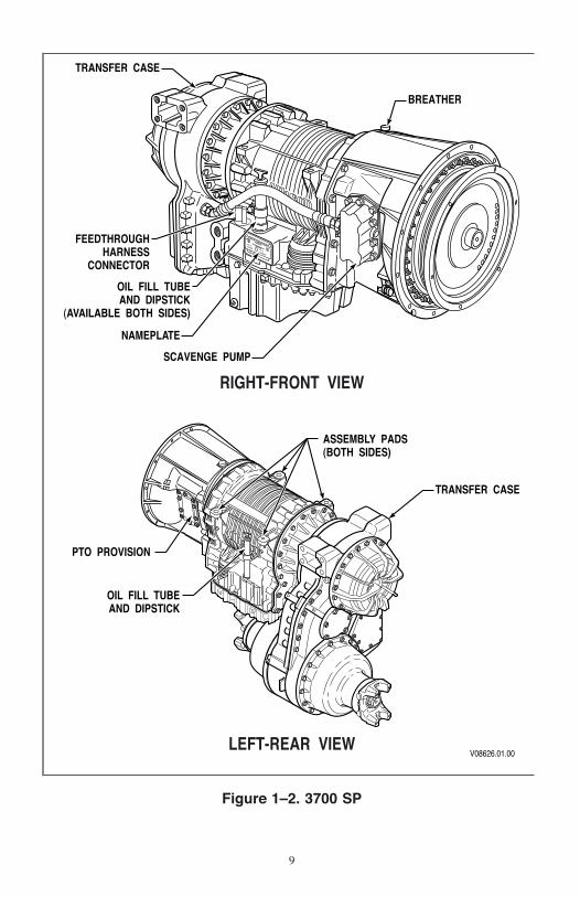
RIGHT-FRONT VIEW
LEFT-REAR VIEW
OIL FILL TUBEAND DIPSTICK
(AVAILABLE BOTH SIDES)
NAMEPLATE
TRANSFER CASE
BREATHER
SCAVENGE PUMP
ASSEMBLY PADS(BOTH SIDES)
TRANSFER CASE
PTO PROVISION
OIL FILL TUBEAND DIPSTICK
FEEDTHROUGHHARNESS
CONNECTOR
Figure 1–2. 3700 SP
9

V01725.00.01
MAINC2
C4
C1
LU
C3C6
C5
Figure 1–3. 3700 SP Transmission—Bottom View
V01726.00.01
T-CASECONNECTOR
C7MAIN
Figure 1–4. 3700 SP Transfer Case—Front View
10

2–1. PERIODIC INSPECTION AND CARE
a. Transmission Inspection. Clean and inspect the exterior of the transmissionat regular intervals. Severity of service and operating conditions determine thefrequency of these inspections. Inspect the transmission for:
• Loose bolts—transmission and mounting components.
• Fluid leaks—repair immediately.
• Loose, dirty, or improperly adjusted throttle sensor.
• Damaged or loose hoses.
• Worn, frayed, or improperly routed electrical harnesses.
• Worn or damaged electrical connectors.
• Dented, worn or out-of-phase driveline U-joints and slip fittings.
• Clogged or dirty breather (vent assembly).
• Check transmission fluid for evidence of engine coolant.
b. Vehicle Inspection. Check the vehicle cooling system occasionally forevidence of transmission fluid. Transmission fluid in the vehicle cooling systemindicates a faulty oil cooler.
c. Welding.
CAUTION: When welding on the vehicle:• DO NOT WELD on the vehicle without disconnecting from the
TCM all control system wiring harness connectors.• DO NOT WELD on the vehicle without disconnecting TCM
battery power and ground leads.• DO NOT WELD on any control components.• DO NOT CONNECT welding cables to any control components.
A label describing on-vehicle welding precautions (ST2067EN) is available fromyour authorized Allison service dealer and should be installed in a conspicuousplace. A vehicle used in a vocation that requires frequent modifications or repairsinvolving welding must have an on-vehicle welding label.
PREVENTIVEMAINTENANCE Section II
11
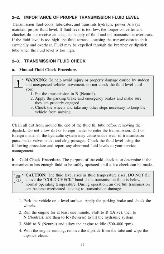
2–2. IMPORTANCE OF PROPER TRANSMISSION FLUID LEVEL
Transmission fluid cools, lubricates, and transmits hydraulic power. Alwaysmaintain proper fluid level. If fluid level is too low, the torque converter andclutches do not receive an adequate supply of fluid and the transmission overheats.If the fluid level is too high, the fluid aerates—causing the transmission to shifterratically and overheat. Fluid may be expelled through the breather or dipsticktube when the fluid level is too high.
2–3. TRANSMISSION FLUID CHECK
a. Manual Fluid Check Procedure.
WARNING: To help avoid injury or property damage caused by suddenand unexpected vehicle movement, do not check the fluid level untilyou:
1. Put the transmission in N (Neutral).2. Apply the parking brake and emergency brakes and make sure
they are properly engaged.3. Chock the wheels and take any other steps necessary to keep the
vehicle from moving.
Clean all dirt from around the end of the fluid fill tube before removing thedipstick. Do not allow dirt or foreign matter to enter the transmission. Dirt orforeign matter in the hydraulic system may cause undue wear of transmissionparts, make valves stick, and clog passages. Check the fluid level using thefollowing procedure and report any abnormal fluid levels to your servicemanagement.
b. Cold Check Procedure. The purpose of the cold check is to determine if thetransmission has enough fluid to be safely operated until a hot check can be made.
CAUTION: The fluid level rises as fluid temperature rises. DO NOT fillabove the “COLD CHECK” band if the transmission fluid is belownormal operating temperature. During operation, an overfull transmissioncan become overheated, leading to transmission damage.
1. Park the vehicle on a level surface. Apply the parking brake and chock thewheels.
2. Run the engine for at least one minute. Shift to D (Drive), then toN (Neutral), and then to R (Reverse) to fill the hydraulic system.
3. Shift to N (Neutral) and allow the engine to idle (500–800 rpm).
4. With the engine running, remove the dipstick from the tube and wipe thedipstick clean.
12

5. Insert the dipstick into the tube until it stops then remove it. Check thefluid level reading. Repeat the check procedure to verify the reading.
6. If the fluid level is within the “COLD CHECK” band, the transmission maybe operated until the fluid is hot enough to perform a “HOT RUN” check.If the fluid level is not within the “COLD CHECK” band, add or drain asnecessary to bring it to the middle of the “COLD CHECK” band.
7. Perform a hot check at the first opportunity after the normal operatingsump temperature of 71°C–93°C (160°F–200°F) is reached.
c. Hot Check Procedure.
CAUTION: When performing the Hot Check procedure, the fluid mustbe at operating temperature to be sure of an accurate check and helpprevent transmission damage. The fluid level rises as temperature rises.During operation an overfull transmission can become overheatedleading to transmission damage.
1. Operate the transmission in D (Drive) until normal operating temperaturesare reached:
• Sump temperature 71°C–93°C (160°F–200°F)
• Converter-out temperature 82°C–104°C (180°F–220°F)
• If the transmission temperature gauge is not present, check fluid levelwhen the engine water temperature gauge has stabilized and thetransmission has been operated under load for at least one hour.
2. Park the vehicle on a level surface and shift to N (Neutral). Apply theparking brake and chock the wheels. Allow the engine to idle(500–800 rpm).
3. With the engine running, remove the dipstick from the tube and wipe clean.
4. Insert the dipstick into the tube until it stops. Then remove it. Check fluidlevel reading.
5. Repeat the check procedure to verify the reading.
NOTE: Safe operating level is within the “HOT RUN” band on thedipstick. The “HOT RUN” band is between the “HOT FULL” and the“HOT ADD” bands. Refer to Figure 2–1.
6. If the fluid level is not within the “HOT RUN” band, add or drain asnecessary to bring the fluid level to within the “HOT RUN” band.
13

d. Consistency of Readings. Always check the fluid level at least twice, withthe engine running. Consistency (repeatable readings) is important for maintainingaccuracy of readings. If readings are still inconsistent, contact your nearest Allisondistributor or dealer.
2–4. KEEPING FLUID CLEAN
Prevent foreign material from entering the transmission by using clean containers,fillers, etc. Lay the dipstick in a clean place while filling the transmission.
V07310.06.00
NOTE: Calibrate level marking locations with respect to transmission control modulesplit line and fill tube.Scale none.
* Dimension determined by installation.
HOT
ADDHO
TFULL
COLD
ADDCO
LDFULL
3700 SP7.00 in. 45.7 mm(1.80 in.)
63.5 mm(2.50 in.)
* 86.6 mm(3.41 in.)
5.9 mm(0.23 in.)
101.6 mm(4.00 in.)
TRANSMISSION/SUMPDESCRIPTION
OILSUMP
DIMENSIONC
DIMENSIONB
DIMENSIOND
DIMENSIONE
DIMENSIONF
DIMENSIONA
TRANSMISSION CONTROL MODULESPLIT LINE
FILLTUBE
6.35 mm (0.250 in.) REFERENCEBlade can be as narrow as
4.76 mm (0.187 in.).
Figure 2–1. Standard 3700 SP Dipstick Markings
14
CAUTION: Containers or fillers that have been used for antifreezesolution or engine coolant must NEVER be used for transmission fluid.Antifreeze and coolant solutions contain ethylene glycol which, if putinto the transmission, can cause the clutch plates to fail.
2–5. FLUID RECOMMENDATIONS
The hydraulic fluid (oil) used in the transmission are important influences ontransmission performance, reliability, and durability. Any fluids meeting TES 295or DEXRON®–III specifications are acceptable for 3700 SP applications.TranSynd™ is a full synthetic transmission fluid developed by AllisonTransmission and Castrol Ltd. and is fully qualified to the Allison TransmissionTES 295 specifications.
DEXRON®-III fluids are also acceptable for on-highway applications. To makesure a fluid is qualified for use in Allison transmissions, check for fluid license orapproval numbers on the container, or consult the lubricant manufacturer. Consultyour Allison Transmission dealer or distributor before using other fluid types.
CAUTION: Disregarding minimum fluid temperature limits can resultin transmission malfunction or reduced transmission life.
When choosing the optimum viscosity grade of fluid, duty cycle, preheatcapabilities, and/or geographical location must be taken into consideration. Table2–1 lists the minimum fluid temperatures at which the transmission may be safelyoperated without preheating the fluid. Preheat with auxiliary heating equipment orby running the equipment or vehicle with the transmission in N (Neutral) for aminimum of 20 minutes before attempting range operation.
15

Table 2–1. Transmission Fluid Operating Temperature Requirements
Ambient Temperature Below Which Preheat isRequired
Viscosity Grade Celsius FahrenheitTranSynd™/SAE 0W–20* –30 –22DEXRON®–III –25 –13SAE 10W –20 –4SAE 10W–30 –20 –4SAE 10W–40 –15 5SAE 30W 0 32SAE 40W 10 50*“Arctic” as defined by MIL-L-46167B (Ref. SIL 13-TR-90)
2–6. FLUID AND FILTER CHANGE INTERVAL RECOMMENDATIONS
a. Frequency.
CAUTION: Transmission fluid and filter change frequency isdetermined by the severity of transmission service. More frequentchanges can be necessary than recommended in the general guidelineswhen operating conditions create high levels of contamination oroverheating.
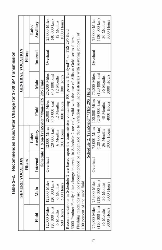
Table 2–2, Recommended Fluid/Filter Change Intervals, is a general guide forfluid and filter change intervals.
NOTE: Mixture is defined as the quantity of oil remaining in thetransmission after a standard fluid change combined with the quantity ofTranSynd™ required to fill the transmission to the proper level. Amixture of TranSynd™ or TES 295 equivalent vs non TranSynd™, otherthan is defined in this paragraph does not meet the requirements thatpermit the eligibility for the recommendations given in this schedule.
16
Tab
le2–
2.R
eco
mm
end
edF
luid
/Filt
erC
han
ge
for
3700
SP
Tran
smis
sio
n
SEV
ER
EV
OC
AT
ION
GE
NE
RA
LV
OC
AT
ION
Flu
id
Filt
ers
Flu
id
Filt
ers
Mai
nIn
tern
alL
ube/
Aux
iliar
yM
ain
Inte
rnal
Lub
e/A
uxili
ary
Sche
dule
1.N
on-T
ranS
ynd™
/Non
-TE
S29
5F
luid
12,0
00M
iles
(20
000
km)
6M
onth
s50
0H
ours
12,0
00M
iles
(20
000
km)
6M
onth
s50
0H
ours
Ove
rhau
l12
,000
Mile
s(2
000
0km
)6
Mon
ths
500
Hou
rs
25,0
00M
iles
(40
000
km)
12M
onth
s10
00H
ours
25,0
00M
iles
(40
000
km)
12M
onth
s10
00H
ours
Ove
rhau
l25
,000
Mile
s(4
000
0km
)12
Mon
ths
1000
Hou
rsR
ecom
men
datio
nsin
Sche
dule
2ar
eba
sed
upon
the
tran
smis
sion
cont
aini
ng10
0pe
rcen
tT
ranS
ynd™
orT
ES
295flu
id30
00Pr
oduc
tFa
milyfil
ter
chan
gein
terv
als
inSc
hedu
le2
are
only
valid
with
the
use
ofA
lliso
nG
old
seri
esfil
ters
.Fl
ushi
ngm
achi
nes
are
not
reco
mm
ende
dor
reco
gniz
eddu
eto
vari
atio
nan
din
cons
iste
ncie
sw
ithas
suri
ngre
mov
alof
100
perc
ent
ofth
eus
edflu
id.
Sche
dule
2.T
ranS
ynd™
/TE
S29
5F
luid
75,0
00M
iles
(120
000
km)
36M
onth
s30
00H
ours
75,0
00M
iles
(120
000
km)
36M
onth
s30
00H
ours
Ove
rhau
l75
,000
Mile
s(1
2000
0km
)36
Mon
ths
3000
Hou
rs
150,
000
Mile
s(2
4000
0km
)48
Mon
ths
4000
Hou
rs
75,0
00M
iles
(120
000
km)
36M
onth
s30
00H
ours
Ove
rhau
l75
,000
Mile
s(1
2000
0km
)36
Mon
ths
3000
Hou
rs
17

b. Abnormal Conditions. Transmission fluid must be changed whenever there isevidence of dirt in the fluid or the fluid is discolored, which indicates a hightemperature condition. Fluid analysis will also reveal a high temperature condition.Local conditions, severity of operation, or duty cycle may require more or lessfrequent fluid or filter changes.
c. Fluid Analysis. Transmissions used in high cycle rate applications should usefluid analysis to make sure fluid is changed as soon as needed. Transmissionprotection and fluid change intervals can be optimized by monitoring fluidoxidation according to the tests and limits shown in Table 2–3. Consult your localtelephone directory for fluid analysis firms. To make sure of consistent andaccurate fluid analysis, use only one fluid analysis firm. Refer to the Technician’sGuide for Automatic Transmission Fluid, GN2055EN, for additional information.
Table 2–3. Fluid Oxidation Measurement Limits
Test LimitViscosity ±25 percent change from new fluidTotal Acid Number +3.0* change from new fluidSolids 2 percent by volume maximum*mg of potassium hydroxide (KOH) to neutralize one gram of fluid
2–7. TRANSMISSION FLUID CONTAMINATION
a. Fluid Examination. At each fluid change, examine the drained fluid forevidence of dirt or water. A normal amount of condensation will appear in thefluid during operation.
b. Water. Obvious water contamination of the transmission fluid or transmissionfluid in the cooler (heat exchanger) water indicates a leak between the water andfluid areas of the cooler. Inspect and pressure test the cooler to confirm the leak.Replace leaking coolers.
NOTE: Cooler water can also be contaminated by engine oil. Be sure tolocate the actual source of cooler water contamination.
c. Engine Coolant. Engine coolant in the transmission hydraulic system requiresimmediate action to prevent malfunction and possible serious transmissiondamage. Completely disassemble, inspect, and clean the transmission. Remove alltraces of the coolant and varnish deposits resulting from engine coolantcontamination (ethylene glycol).
Any trace of glycol or greater than 0.2 percent water contamination requirescomplete disassembly and clean up of the transmission and replacement of seals,
18

gaskets, clutch plates, and bearings. Solenoid resistance should be measured andchecked against the specifications. Solenoids not within specification should bereplaced. Replace diagnostic pressure switch PS1. Reference Service InformationLetter 18-TR-98, Rev A.
d. Metal. Metal particles in the fluid (except for minute particles normallytrapped in the oil filter) indicate internal transmission damage. If these particlesare found in the sump, the transmission must be disassembled and closelyinspected to find their source. Metal contamination requires complete transmissiondisassembly. Clean all internal and external hydraulic circuits, cooler, and all otherareas where the particles could lodge.
CAUTION: After flushing the cooler, be sure to check the externalcooler circuit restriction. If circuit pressure drop is above specification,the cooler has excessive trapped particles and must be replaced.
2–8. TRANSMISSION FLUID AND FILTER CHANGE PROCEDURE
a. Drain Fluid.
NOTE: Do not drain the transmission if replacing only thefilters.
WARNING: Avoid contact with hot fluid or the sump when drainingtransmission fluid. Direct contact with hot fluid or the hot sump mayresult in bodily injury.
1. Drain the fluid when the transmission is at normal operating sumptemperature—71°C–93°C (160°F–200°F). Hot fluid flows quicker anddrains more completely.
2. Remove the drain plug from the control module and transfer case; allowthe fluid to drain into a suitable container.
3. Examine the fluid as described in Section 2–7, TRANSMISSION FLUIDCONTAMINATION, Paragraph a. Fluid Examination.
b. Replace Filters. Refer to Figure 2–2.
1. Remove twelve bolts 1, two filter covers 2, two gaskets 3, two O-rings 4,two O-rings 5, and two filters 6 from the bottom of the control module.
2. When reinstalling parts, lubricate and install new O-rings 4 and 5 on eachcover. Lubricate O-ring inside filter 6 and push filter onto each cover 2.
19

Install new gaskets 3 on each cover 2 and align bolt holes in gasket withholes in cover.
3. Install filter cover assemblies into the filter compartments. Align eachfilter/cover assembly with the holes in the bottom of the control module.Push the cover assemblies in by hand to seat the seals.
CAUTION: Do not use the bolts to draw the filter covers to the controlmodule. Do not use an impact wrench to tighten the bolts. Using animpact wrench to tighten the bolts may cause stripped threads andexpensive parts replacement. Use a torque wrench to tighten the bolts.
4. Install six bolts into each cover assembly and tighten to 51–61 N•m(38–45 lb ft).
5. Replace the drain plug O-ring. Install the drain plug and tighten to25–32 N•m (18–25 lb ft).
LUBEV09547.00.00MAIN
6
54
21
3LUBEM
AIN
Figure 2–2. Location of Filters for Service
20

c. Refill Transmission. Refer to Table 2–4 for fluid refill quantities. The amountof refill fluid is less than the amount used for the initial fill. Fluid remains in theexternal circuits and transmission cavities after draining the transmission.
After refill, check the fluid level using the procedure described in Section 2–3,TRANSMISSION FLUID CHECK.
Table 2–4. 3700 SP Transmission Fluid Capacity
Initial Fill* Refill*Liters Quarts Liters Quarts
37 39 30 32*Approximate quantity; does not include external lines and cooler hose.
2–9. FLUID LEAK DIAGNOSIS
a. Finding the Leak.
1. Identify the fluid. Determine whether the fluid is engine oil, automatictransmission fluid, or hydraulic fluid from a particular vehicle system.
2. Operate the vehicle to reach normal operating temperature and park thevehicle. Inspect the vehicle to identify the source of the leak. Refer to thefollowing list for possible points of transmission fluid leaks and theircauses.
• Transmission mating surfaces:
— Attaching bolts not correctly aligned
— Improperly installed or damaged gasket
— Mating surface(s) damaged
• Housing leak:
— Fill tube or plug seal damaged or missing
— Fill tube bracket dislocated
— Oil cooler connector fittings loose or damaged
— Output shaft seals worn-out or damaged
— Pressure port plugs loose
— Porous casting
• Leak at converter end:
— Converter seal damaged
— Seal lip cut—check converter hub for damage
— Garter spring missing from seal
21
— Converter leak in weld area or O-ring seal
— Porous casting
• Fluid comes out of fill tube:
— Overfilled—incorrect dipstick
— Plugged breather
— Water or coolant in fluid—fluid appears milky
— Incorrect electronic fluid indication
— Drain-back holes plugged
3. Visually inspect the suspected area. Inspect all gasket mating surface forleaks.
4. If the leak still cannot be identified, clean the suspected area with adegreaser, steam, or spray solvent. Clean and dry the area. Operate thevehicle for several miles at varying speeds. Inspect the vehicle for leaks. Ifthe leak source still cannot be identified, use the powder method, and/orthe black light and dye method as explained below.
b. Powder Method.
1. Clean the suspected area.
2. Apply an aerosol-type white powder to the suspected area.
3. Operate the vehicle under normal operating conditions.
4. Visually inspect the suspected area and trace the leak path over the whitepowder.
c. Black Light and Dye Method. A dye and black light kit for finding leaks isavailable. Refer to the manufacturer’s directions when using the kit. Refer to thekit directions for the color of the fluid/dye mix.
1. Pour the specified amount of dye into the transmission fill tube.
2. Operate the vehicle under normal operating conditions.
3. Direct the black light toward the area suspected of leaking. Dyed fluid willappear as a brightly colored path leading to the source of the leak.
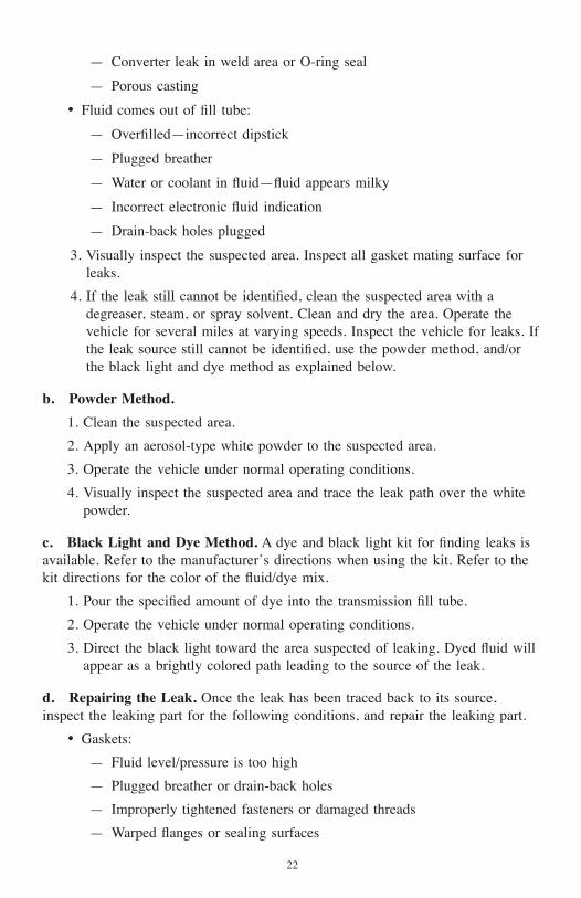
d. Repairing the Leak. Once the leak has been traced back to its source,inspect the leaking part for the following conditions, and repair the leaking part.
• Gaskets:
— Fluid level/pressure is too high
— Plugged breather or drain-back holes
— Improperly tightened fasteners or damaged threads
— Warped flanges or sealing surfaces
22

— Scratches, burrs, or other damage to sealing surfaces
— Damaged or worn-out gasket
— Cracked or porous casting
— Improper sealant used, where applicable
• Seals:
— Fluid level/pressure is too high
— Plugged breather or drain-back hole
— Damaged seal bore
— Damaged or worn-out seal
— Improper seal installation
— Cracks in component
— Output shaft surface scratched, nicked, or damaged
— Loose or worn-out bearing causing excess seal wear
• Sealing Flange:
— Inspect the sealing flange for bends; replace the sealing flange if bent.
2–10. BREATHER
a. Location and Purpose. The breather is located on top of the transmissionconverter housing. The breather prevents air pressure build-up within thetransmission and its passage must be kept clean and open.
b. Maintenance. The amount of dust and dirt encountered will determine thefrequency of breather cleaning. Use care when cleaning the transmission.
CAUTION: DO NOT SPRAY STEAM, WATER, OR CLEANINGSOLUTION DIRECTLY AT THE BREATHER. Spraying steam,water, or cleaning solution at the breather can force water or cleaningsolution into the transmission and contaminate transmission fluid.
c. Replacement. Always use a correctly sized wrench to remove or replace thebreather. Using pliers or a pipe wrench can crush or damage the breather stem andproduce metal particles which could enter the transmission. Tighten the breather to12–16 N•m (9–12 lb ft).
23

2–11. TROUBLESHOOTING
a. CHECK TRANS Light.
NOTE: Strip pushbutton shift selectors cannot display or cleardiagnostic codes.
The CHECK TRANS light is usually located on the vehicle’s instrument panel.
When the light is “ON” and the shift selector display is flashing, shifts are beinginhibited by the TCM.
• This occurs when the TCM senses abnormal conditions in the transmission.
• During this time, the digit on the shift selector displays the range in whichthe transmission is locked.
• The transmission may continue to operate with inhibited shifts.
• The TCM will not respond to shift selector requests.
• Direction changes and shifts to and from neutral will not occur.
• If the ignition is turned “OFF” and then “ON” while the CHECK TRANSlight is illuminated, the transmission will remain in neutral until thediagnostic code is cleared.
Whenever the CHECK TRANS light is illuminated, the TCM logs a diagnosticcode in memory. The diagnostic codes can be accessed through the shift display orthe Allison DOC™.
NOTE: Diagnostic codes can be logged without illuminating theCHECK TRANS light. This occurs when the TCM senses a problembut determines that the problem will not cause immediate transmissiondamage or dangerous performance.
24

b. Diagnostic Codes.
Table 2–5. Diagnostic Codes Overview
CodeList
Position DTC Active* Historic**CheckTrans
FailureRecord** Description**
d1 P0880 Y Y N YTCM PowerInput Signal
d2 P2723 Y Y Y Y
PressureControlSolenoid 1Stuck Off
d3 P0727 N Y N YEngine SpeedInput CircuitNo Signal
d4 P0610 N Y N YTCM Vehicleoptions(TransID) Error
d5 — — — — — —* On Shift Selector, Y = Mode Indicator (LED) illuminated** Accessible only by Allison DOC™.
Diagnostic codes are stored in memory. Up to five codes can be stored, with themost recent code stored displayed first.
Diagnostic codes consist of the letter “P” or “U” followed by four numbers. Theletter “P” indicates a transmission internal problem while a “U” indicates aproblem in a vehicle system or the transmission to vehicle interface.
• The first two digits indicate the type of problem.
• Code List Position (shift selector only). The position which a codeoccupies in the code list. Positions are displayed as “d1” through “d5”(Code List Position 1 through Code List Position 5).
• DTC. The diagnostic trouble code number referring to the general conditionor area of fault detected by the TCM. When using Allison DOC™, “doubleclick” on the numerical code in the DTC column to link to the specifictroubleshooting instructions for the DTC.
• Active Indicator. Indicates when a diagnostic code is active. The MODEindicator LED on the shift selector is illuminated or the diagnostic tooldisplays Y when the DTC is active.
• Historic Indicator. Indicates when the DTC has met sufficient criteria to bestored in the long term memory. “Sufficient criteria” may mean the DTCoccurred over a specific span of time or over multiple test cycles.
25

• Check Trans Indicator. Indicates when the TCM is requesting CHECKTRANS light as a result of the DTC.
• Failure Records Indicator. Indicates when Failure Records are present.“Double click” on the Y in the Failure Records column to display failurerecord information.
• Description. Provides a brief description of the DTC. “Double click” on theDTC description to link to the specified troubleshooting instructions for theDTC.
NOTE: Diagnostic codes are displayed two characters or digits at atime. For example, code C1312 is displayed as d1, C, 13, 12. Code listposition = d1. First pair, “Blank” C. Second pair of characters = 13.Third pair of characters = 12. Each character pair is displayed for aboutone second.
When using the shift selector to retrieve trouble codes, if the mode indicator(LED) is illuminated, the displayed code is active. If the mode indicator is notilluminated, the displayed code is inactive. In normal operating mode, anilluminated mode indicator signifies secondary mode operation.
c. Clearing Trouble Codes Using Shift Selector.
NOTE: Strip pushbutton shift selectors cannot display or cleardiagnostic codes.
During installation, “false” codes can be recorded in the TCM’s memory. Clearthese codes before road testing the vehicle. Use the shift selector to clear thecodes (refer to Figure 2–3).
• Enter the diagnostic mode on pushbutton selectors by pressing the ↑ (Up)and ↓ (Down) arrow simultaneously. Simultaneously press both buttonstwice if there is an oil level sensor present.
• With a lever selector, enter the diagnostic mode by momentarily pressingthe MODE button.
• To clear all active indicators, press and hold the MODE buttonapproximately 3 seconds until the mode indicator (LED) flashes.
• To remove all codes, press and hold the MODE button for approximatelyten seconds until the mode indicator (LED) flashes again.
26

d. Retrieving Troubleshooting Codes.
NOTE: Strip pushbutton shift selectors cannot display or cleardiagnostic codes.
After road testing the vehicle, check for diagnostic codes. Retrieve the codes byusing the shift selector (refer to Figure 2–3).
NOTE: Diagnostic codes are displayed two characters or digits at atime. For example, code C1312 is displayed as d1, C, 13, 12. Code listposition = d1. First pair, “Blank” C . Second pair of characters = 13.Third pair of characters = 12. Each character or pair is displayed forabout one second.
1. Enter Diagnostic Mode.
2. The display will list the code’s logged position (d1, d2, d3, etc.), thenfollow with the code letter designator (C, P, or U), the first two numbers ofthe code, and then the last two numbers of the code (this display sequencerepeats until the MODE button is pressed again).
3. Momentarily press the MODE button to move to the next code stored inmemory.
4. When the MODE button is pressed after displaying the code in the d5position, the code in the d1 position is displayed.
NOTE: You can also use Allison DOC™ to clear and retrieve thetroubleshooting codes. Refer to the Allison DOC™ for PC–Service ToolUser Guide for specific instructions.
27
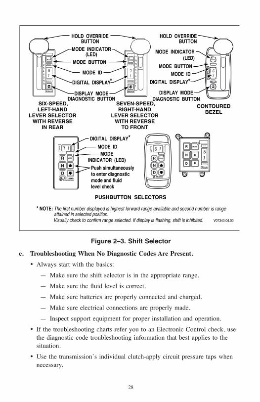
e. Troubleshooting When No Diagnostic Codes Are Present.
• Always start with the basics:
— Make sure the shift selector is in the appropriate range.
— Make sure the fluid level is correct.
— Make sure batteries are properly connected and charged.
— Make sure electrical connections are properly made.
— Inspect support equipment for proper installation and operation.
• If the troubleshooting charts refer you to an Electronic Control check, usethe diagnostic code troubleshooting information that best applies to thesituation.
• Use the transmission’s individual clutch-apply circuit pressure taps whennecessary.
61
71
61
MODE
61
RND654321
12345DNR
7 1
V07343.04.00
SIX-SPEED,LEFT-HAND
LEVER SELECTORWITH REVERSE
IN REAR
SEVEN-SPEED,RIGHT-HAND
LEVER SELECTORWITH REVERSE
TO FRONT
HOLD OVERRIDEBUTTON
HOLD OVERRIDEBUTTON
MODE ID MODE ID
*
MODE INDICATOR(LED) MODE INDICATOR
(LED)
MODE IDMODE
INDICATOR (LED)Push simultaneouslyto enter diagnosticmode and fluidlevel check
NOTE: The first number displayed is highest forward range available and second number is rangeattained in selected position.Visually check to confirm range selected. If display is flashing, shift is inhibited.
*
DIGITAL DISPLAY*
PUSHBUTTON SELECTORS
*
CONTOUREDBEZEL
MODE BUTTONMODE BUTTON
DIGITAL DISPLAYDIGITAL DISPLAY
DISPLAY MODEDIAGNOSTIC BUTTON
DISPLAY MODEDIAGNOSTIC BUTTON
Figure 2–3. Shift Selector
28

f. Troubleshooting Intermittent Diagnostic Codes. Intermittent codes are aresult of conditions which are not always present.
When conditions causing the code exist, the code is logged in memory. The codestays in memory until it is manually cleared or cycled out.
When intermittently occurring codes exist, check for the following items:
• Dirty, damaged, or corroded harness connectors and terminals
• Terminals not fully seated in connectors
• Damaged harnesses (due to poor routing, chafing, excessive heat, tightbends, etc.)
• Improperly mounted electronic control components
• Poor connector seals (where applicable)
• Exposed harness wires
• EMI generating components and accessories
• Loose ground connections
To help locate intermittent problems it sometimes helps to place the appropriatetester on the suspect component or circuit and simulate operatingconditions—wiggle, pull, bump, and bend while watching the tester.
29

g. Exiting Diagnostic Mode.
NOTE: Strip pushbutton shift selectors cannot display or cleardiagnostic codes.
To exit the diagnostic mode, do one of the following:
• Do nothing; wait until the calibrated time has passed and the systemautomatically returns to normal operation.
• Using a pushbutton shift selector, simultaneously press the ↑ (Up) and↓ (Down) arrow buttons.
• Using a pushbutton shift selector, press N (Neutral).
• Using a lever shift selector, press the MODE button once.
• If using a lever shift selector, move the selector lever to any position otherthan the one it was in when the diagnostic display mode was activated.
2–12. TRANSMISSION STALL TEST
a. Purpose. Stall testing is performed to determine if a vehicle performancecomplaint is due to an engine or transmission malfunction. Stall testing is atroubleshooting procedure only—never perform a stall test as a general check orduring routine maintenance.
Transmission stall speed is the maximum engine rpm attainable when the engineis at full throttle and the torque converter turbine is not moving, or “stalled.” Aftera transmission stall test, compare the actual full throttle engine speed at torqueconverter turbine stall with specifications established by the vehicle manufacturer.
NOTE: Engine speed data can be obtained from the enginemanufacturer or from the equipment dealer or distributor. Some enginemanufacturers provide a programmable parameter to limit engine speedwhen the transmission output speed is 0 rpm, such as at a stop. Thisparameter should be set to a higher value than the expected transmissionstall speed before performing the stall test.
b. Stall Testing Preparation. If a transmission stall test is to be performed,make sure the following preparations have been made before conducting thetransmission stall test:
1. The manufacturer concurs with performing a full-throttle transmission stalltest.
2. The engine programmable parameter for 0 rpm transmission output speed isset higher than the value expected at transmission stall speed.
30

3. The vehicle is in an area in which a transmission stall test can be safelyperformed.
4. Make sure the fuel control linkage goes to full throttle and does not stickwhen released.
5. Make sure the engine air induction system and exhaust system have norestrictions.
6. Perform a cold check of the transmission fluid level and adjust asnecessary.
7. Connect theAllison DOC™ to the vehicle diagnostic data connector orinstall an accurate tachometer (do not rely on the vehicle tachometer).
8. Install a temperature gauge with the probe in the transmission converter-out(to cooler) line. Allison DOC™ displays sump temperature only.
9. Install wheel chocks
10. A driver is in the driver’s position.
11. The vehicles brakes are fully locked.
WARNING: To help avoid personal injury, such as burns, from hottransmission fluid and/or to help avoid equipment damage, do not stallthe torque converter for more than ten seconds maximum and monitortransmission fluid temperature. Immediately return the engine to idle ifconverter out (to cooler) temperature exceeds 150°C (300°F). Operatingthe transmission at high engine power at transmission stall or near stallconditions causes a rapid rise in the transmission fluid temperature. Thefluid in the transmission torque converter is absorbing all of the enginepower and the vehicle cooling system cannot dissipate the excessiveheat load. Extended operation under high heat load conditions causestransmission and cooling system damage, and can possibly fail hydrauliclines causing leaking high temperature fluid.
WARNING: To help avoid personal injury and equipment damagewhile conducting a transmission stall test, the vehicle must be positivelyprevented from moving. Apply the parking brake, the service brake, andchock the wheels securely. Warn personnel to keep clear of the vehicleand its travel path.
c. Performing a Transmission Stall Test.
1. Start the engine. While in neutral let the transmission warm to normaloperating temperature:
— Sump temperature 71–93°C (160–200°F)
— Converter out temperature 82–104°C (180–220°F)
31

2. Perform a hot check of the transmission fluid level and adjust as necessary.
3. Turn all engine accessories OFF.
4. Place Allison DOC™ diagnostic tool in clutch test mode. Use the shiftselector to select 4th range. Using 4th range reduces the torque imposed onthe transmission driveline. Do not perform a transmission stall test inReverse or Low range.
CAUTION: To help avoid transmission or driveline damage, fullthrottle stall tests must not be performed in R (Reverse) range, allmodels, or low ranges, seven-speed models.
5. Notify personnel in the area to keep clear of the vehicle.
6. Slowly increase engine rpm until engine speed stabilizes.
7. Record engine speed.
CAUTION: The transmission stall test procedure causes a rapid rise intransmission fluid temperature that can damage the transmission. Nevermaintain a stall condition once engine speed stabilizes or converter out(to cooler) temperature exceeds 150°C (300°F). During a stall condition,converter out temperature rises much faster than the internal (sump)temperature. Never use sump fluid temperature to determine the lengthof the stall condition. If the stall test is repeated, do not let the engineoverheat.
8. Record converter out (to cooler) temperature.
9. Reduce the engine speed to idle and shift the transmission to neutral.
10. Raise engine speed to 1200–1500 rpm for 2 minutes to cool transmissionfluid.
11. At the end of two minutes, record converter out (to cooler) temperature.
12. Proceed to the Neutral Cool Down Check paragraph 2–12 item g.
d. Driving Transmission Stall Test.
NOTE: If the vehicle is equipped with a smoke controlled or anemission controlled engine or engine control programming inhibitingengine acceleration, the following stall test procedure can be used.
WARNING: To help avoid personal injury and/or equipment damage, adriving transmission stall test must be performed by a trained driver anda qualified technician.
32

e. Driving Transmission Stall Test Preparation. If a driving transmission stalltest is to be performed, make sure the following preparations have been madebefore conducting the test.
1. The manufacturer concurs with performing a full-throttle transmission stalltest.
2. The engine programmable parameter for 0 rpm transmission output speed isset higher than the value expected at transmission stall speed.
3. The vehicle is in an area in which the transmission stall test can be safelyperformed.
4. Make sure the fuel control linkage goes to full throttle and does not stickwhen released.
5. Inspect the engine air induction system and exhaust system to make surethere are no restrictions.
6. Perform a cold check of the transmission fluid level and adjust asnecessary.
7. Connect Allison DOC™ to the vehicle diagnostic data connector.
8. Install an accurate tachometer (do not rely on the vehicle tachometer).
9. Install a temperature gauge with the probe in the transmission converter-out(to cooler) hose. Allison DOC™ displays sump temperature only.
f. Performing A Driving Transmission Stall Test.
CAUTION: The transmission stall test procedure causes a rapid rise intransmission fluid temperature that can damage the transmission. Nevermaintain a stall condition once engine speed stabilizes or converter out(to cooler) temperature exceeds 150°C (300°F). During a stall condition,converter out temperature rises much faster than the internal (sump)temperature. Never use sump fluid temperature to determine the lengthof the stall condition. If the stall test is repeated, do not let the engineoverheat.
1. Start the engine. While in Neutral let the transmission warm to normaloperating temperature:
a. Sump temperature 71–93°C (160–200°F)
b. Converter out temperature 82–104°C (180–220°F)
2. Perform a hot check of the transmission fluid level and adjust as necessary.
3. Turn all engine accessories OFF.
4. While located in an isolated area, begin the driving transmission stall test.
33
5. Select a hold range that will limit road speed (usually 2nd or 3rd range).Never perform a driving stall test in Reverse or Low range (seven speedmodels)
6. Operate the engine at 100 percent full throttle, maximum governed speed.
7. With the engine at maximum governed speed, begin gradually applying thevehicle service breaks while maintaining 100 percent full throttle. When thevehicle comes to a complete stop, record engine speed.
8. Record converter out (to cooler) temperature.
9. Reduce the engine speed to idle and shift the transmission to neutral.
10. Raise engine speed to 1200–1500 rpm for two minutes to cooltransmission fluid. At the end of two minutes, record converter out (tocooler) temperature.
11. Proceed to the Neutral Cool Down Check paragraph 2–12 item g.
g. Neutral Cool-Down Check Procedure.
1. At the end of two minutes the converter out (to cooler) fluid temperatureshould return to within normal operating temperature range.
2. If the transmission fluid does not cool within two minutes, the cause couldbe a stuck torque converter stator or an issue with the transmission cooler,lines or fittings.
h. Transmission Stall Test Results.
NOTE: Environmental conditions, such as ambient temperature,altitude, engine accessory loss variations, etc., affect the power input tothe converter. Due to such conditions, stall speed can vary fromspecification by ±150 rpm and still be accepted as within published stallspeed.
• If engine speed with the transmission stalled is more than 150 rpm belowthe stall speed specification an engine issue is indicated.
• If engine stall speed is more than 150 rpm above specification, atransmission issue is indicated.
• Conditions that can exist to cause stall speed to 150 rpm above specificationcould be:
— Transmission fluid cavitation or aeration. Verify proper fluid levelusing the oil level sensor, if equipped or dipstick.
— Slipping clutch.
— Torque converter malfunction.
— Sticking or damaged torque converter valve.
34

• A low stall speed (at least 33 percent lower than published stall speed)could indicate an engine issue or a freewheeling stator in the torqueconverter.
35
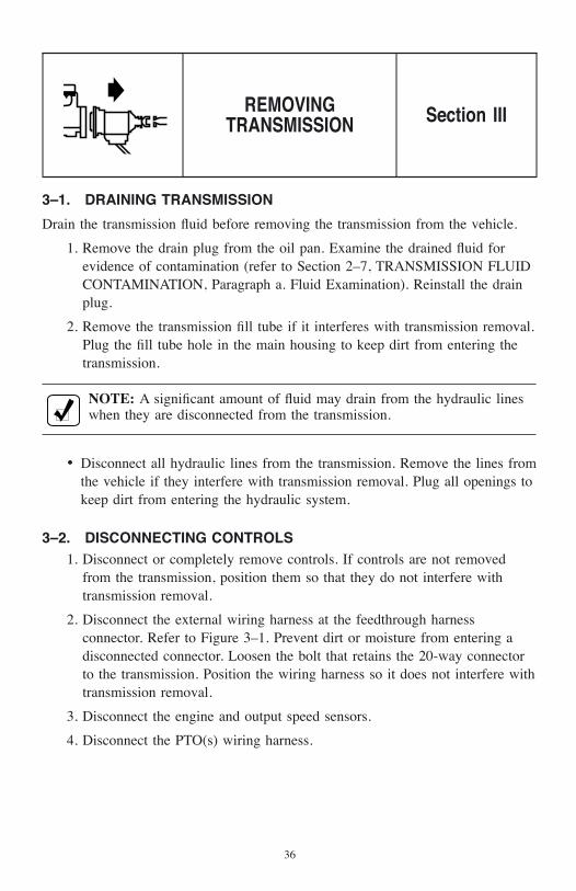
3–1. DRAINING TRANSMISSION
Drain the transmission fluid before removing the transmission from the vehicle.
1. Remove the drain plug from the oil pan. Examine the drained fluid forevidence of contamination (refer to Section 2–7, TRANSMISSION FLUIDCONTAMINATION, Paragraph a. Fluid Examination). Reinstall the drainplug.
2. Remove the transmission fill tube if it interferes with transmission removal.Plug the fill tube hole in the main housing to keep dirt from entering thetransmission.
NOTE: A significant amount of fluid may drain from the hydraulic lineswhen they are disconnected from the transmission.
• Disconnect all hydraulic lines from the transmission. Remove the lines fromthe vehicle if they interfere with transmission removal. Plug all openings tokeep dirt from entering the hydraulic system.
3–2. DISCONNECTING CONTROLS1. Disconnect or completely remove controls. If controls are not removed
from the transmission, position them so that they do not interfere withtransmission removal.
2. Disconnect the external wiring harness at the feedthrough harnessconnector. Refer to Figure 3–1. Prevent dirt or moisture from entering adisconnected connector. Loosen the bolt that retains the 20-way connectorto the transmission. Position the wiring harness so it does not interfere withtransmission removal.
3. Disconnect the engine and output speed sensors.
4. Disconnect the PTO(s) wiring harness.
REMOVINGTRANSMISSION Section III
36

3–3. UNCOUPLING FROM DRIVELINE, ENGINE, AND VEHICLE1. Disconnect the vehicle drive shaft from the transmission output flange or
yoke. Position the disconnected shaft to avoid interference when removingthe transmission.
2. Disconnect PTO connections such as:
a. PTO hydraulic hoses
b. PTO-powered equipment drive shaft
3. If transmission mountings support the rear of the engine, place a jack orother support under the engine.
4. Securely support the transmission with a hoist, jack, or other suitableremoval equipment.
5. Remove all bolts, nuts, washers, spacers, and supports that attach thetransmission to the vehicle and the engine.
World TransmissionManufactured By
Manufactured ByDivision of General Motors Corporation
Division of General Motors Corporation
Indianapolis, Indiana
Indianapolis, Indiana ECAPSOREA E LI B O MOT UA DETI NUACI RE MA F O SREKROWTNE
MELPMI
LARUT
LUCIRG
ADNAUAWUAW933933MODELNO.
SERIAL NO.
XXXXXXX
XXXXXXPART NO.
XX XXXX
V09466.00.00
TRANSFERCASECONNECTOR
ENGINE SPEEDSENSOR
SCAVENGE PUMPNAMEPLATE
COOLERPORTS
BREATHER
FEEDTHROUGHHARNESS CONNECTOR
MOUNTINGPADS
ASSEMBLY PADS
Figure 3–1. 3700 SP Disconnect Locations
37

3–4. REMOVING THE TRANSMISSION1. Move the transmission away from the engine, approximately
110 mm (4.35 inches), until it is completely clear of the engine. If used,remove the adapter ring and/or gasket.
2. Raise or lower the transmission as necessary to remove it from the vehicle.
3–5. REMOVING OUTPUT YOKE
The 3700 SP has two large self-locking nuts. A special procedure must befollowed for removal and installation of each nut.
CAUTION: The use of an impact wrench on the 3700 SP output nutrequires a means to hold the yoke. Failure to hold the yoke can causeinternal damage to the transmission.
1. Remove dirt and burrs from the shaft threads. Then hold the yoke andloosen the nut until there is about a 1/16 inch gap between the nut and theflange.
2. Check the running torque as the nut is being removed. The running torquemust be at least 19.5 N•m (14 lb ft). Discard and replace the nut atinstallation if it does not meet the running torque limit.
38

4–1. CHECKING INPUT COMPONENTS
a. Bolt Holes. Inspect all bolt holes on the front of the transmission and rear ofthe engine that are used in connecting the transmission to the engine. The threadsmust be undamaged and the holes free of chips or foreign material.
b. Pilot Boss. Inspect the pilot boss (at the center of the flywheel) for damage orraised metal that prevents free entry into the crankshaft hub (or adapter).
c. Starter Ring Gear. Inspect the starter ring gear for excessive wear ordamage.
d. Transmission Mounting Flange. Inspect the transmission mounting flangefor raised metal, dirt, or if used, pieces of gasket material.
e. Transmission-to-Engine Mounting. Inspect the transmission-to-enginemounting flange for raised metal, burrs, or pieces of gasket material (if used).Remove any of these defects. Inspect the threaded holes for damaged threads
4–2. INSTALLING OUTPUT YOKE
a. Output Oil Seal. Inspect the output oil seal for leaks or damage. Refer to thelatest edition of the approved Service Manual for replacement instructions. If notreplacing the oil seal, lubricate it with high-temperature grease or transmissionfluid.
CAUTION: DO NOT attempt to polish the oil seal contact surface onthe yoke. Scratches or machine-type lead can cause the seal to leak.
b. Inspect Yoke. Inspect each yoke for damage or wear. The oil seal contactsurface must be smooth and regular to prevent oil leaking past the seal. Rotate theyoke after installation to check for binding.
TRANSMISSIONPREPARATION Section IV
39

c. Install Output Yokes.
1. Install the rear output yoke on the rear output shaft. Tighten the nut to610–815 N•m (450–600 lb ft). Follow the same procedure for the frontoutput yoke.
2. Tighten bolt to 70–80 N•m (52–59 lb ft).
4–3. INSTALLING PTO
Access to the PTO mounting pads and the space available to maneuver thetransmission determine whether the PTO should be installed before or after thetransmission is installed.
CAUTION: DO NOT use cork or other soft gaskets to install the PTO.Use only the shims/gaskets listed in the appropriate parts catalogs. Referto Table 8–1 for the latest publication number.
NOTE: DO NOT use sealing compounds—they are usuallyincompatible with automatic transmission fluid.
a. Install Guide Pins. Guide pins are included in the PTO manufacturersinstallation kit. Determine the required position of the guide pins in relation to themounted position of the PTO. The guide pins must align with the two blind holesin the PTO pad. Install two headless guide pins into the converter-housing PTOpad. Tighten the pins.
b. Install Gasket. Install the special gasket over the guide pins—ribbed surfaceaway from the transmission.
c. Mount the PTO. Mount the PTO on the guide pins, meshing the PTO drivengear with the transmission PTO drive gear. Retain the PTO by installing a bolt inthe top bolt hole. Install the remaining bolts. Tighten all bolts to 51–61 N•m(38–45 lb ft).
4–4. INSTALLING SCAVENGE PUMP
Determine whether the scavenge pump should be installed before or after thetransmission has been installed.
a. Install Guide Pins. Guide pins are included in the scavenge pump installationkit. Determine the required position of the guide pins in relation to the mountedposition of the scavenge pump. The guide pins must align with the two blindholes in the scavenge pump. Install two headless guide pins into the converterhousing scavenge pump pad. Tighten the pins.
40

b. Install Gasket. Install the special gasket over the guide pins—ribbed surfaceaway from the transmission.
c. Mount the Scavenge Pump. Mount the scavenge pump on the guide pins,meshing the scavenge pump with the transmission’s PTO drive gear. Retain thescavenge pump by installing a bolt in the top bolt hole. Install the remainingeights bolts and tighten the bolts to 51–61 N•m (38–45 lb ft).
4–5. INSTALLING FILL TUBE AND SEAL
a. Location. The fill tube may be mounted on either the right or left side. Theunused fill tube provision must have a plug to fill the tube opening.
CAUTION: Install the fill tube bracket with the correct length bolt. Abolt that is too long may cause cracks and leaks in the main housing.Refer to the appropriate parts catalog for the correct bolt.
b. Installation. Install the fill tube seal into the main housing. Insert the fill tubethrough the seal. Align the tube bracket with its bolt location. Install the fill tubebolt and tighten to 24–29 N•m (18–21 lb ft). Install the expansion plug in theunused fill tube hole tighten the plug to 1–3 N•m (9–26 lb ft).
4–6. CHECKING PLUGS AND OPENINGS
Carefully inspect all sides and the bottom of the transmission for loose or missingplugs.
a. Pressure Plugs. Check that 0.4375–20 UNF-2A pressure plugs are tightenedto 10–13 N•m (7–10 lb ft).
b. Fluid Drain Plug. Check that the drain plug is tightened to 25–32 N•m(18–24 lb ft).
c. Cleanliness. Inspect the openings into which the cooler lines connect fordeformities or obstructions. Check the transmission electrical connectors forcleanliness. Clean electrical connectors with LPS cleaner only (refer to SIL17–TR-94).
41

5–1. ENGINE, TRANSMISSION ADAPTATION REQUIREMENTS
You must make sure a new transmission installation can be adapted to thevehicle’s engine. Use the measurements described in this section to make surecorrect transmission-to-engine adaptation. Refer to AS67–020. Typicalarrangement of adaptation components is shown in Figure 5–1.
a. Measuring Equipment. The following measuring equipment is required:
• 600 mm (24 inch) precision caliper
• 50–100 mm (2–4 inch) telescoping gauge
• 25–76 mm (1–3 inch) outside micrometer
• Dial indicator and mounting attachments—base, posts, and clamps
• 0–150 mm (0–6 inch) depth micrometer
b. Flywheel Housing Pilot Bore Diameter. The flywheel housing pilot borediameter must measure 447.68–447.81 mm (17.625–17.630 inches).
c. Flywheel Housing Bore Runout. Flywheel housing bore runout cannotexceed 0.51 mm (0.020 in) TIR.
d. Flywheel Housing Face Squareness. The flywheel housing face cannot beout-of-square more than 0.51 mm (0.020 inch) TIR.
e. Crankshaft Hub Pilot or Adapter Diameter. The crankshaft hub pilot or hubadapter pilot diameter must measure between 50.94–50.99 mm(2.006–2.008 inches).
f. Crankshaft Hub Pilot or Adapter Squareness. The crankshaft hub or hubadapter cannot be out-of-square more than 0.13 mm (0.005 inch) TIR.
g. Crankshaft Hub Pilot or Adapter Concentricity. The crankshaft hub pilotor the hub adapter pilot concentricity cannot exceed 0.13 mm (0.005 inch) TIR.
h. Flexplate Bolt Hole Flatness. Flexplate flatness in the area of the bolt holesis not a measurement required for the 3700 SP transmissions.
PREPARING VEHICLEFOR TRANSMISSION
INSTALLATIONSection V
42

+
MO
UNTI
NG F
ACE
OF
ENG
INE
FLYW
HEEL
HO
USIN
G
CONV
ERTE
R H
OUS
ING
4-FL
EXPL
ATE
WEA
RPLA
TECR
ANKS
HAFT
BO
LTS
(Con
sult
engi
ne m
anuf
actu
rer f
orto
rque
requ
irem
ents
.)
ACCE
SS H
OLE
FLEX
PLAT
E A
DAPT
ER
STAR
TER
RIN
G G
EAR
10-B
OLT
M8
x 1.
25 x
25.
0 m
m (0
.98
in.)
LO
NGTo
rque
to 3
3–39
N•m
(25–
27 lb
ft)
FLYW
HEEL
HO
USIN
G
CRAN
KSHA
FT H
UB A
DAPT
ER
ENG
INE
CRA
NKSH
AFT
CEN
TERL
INE
BOLT
, FL
EXPL
ATE-
TO-F
LEXP
LATE
ADA
PTER
12-M
8 x
1.25
x V
ario
us le
ngth
sTo
rque
to 3
3–29
N•m
(25–
27 lb
ft)
or 6
-M10
x 1
.5 x
Var
ious
leng
ths
Torq
ue to
63–
73 N
•m (4
6–54
lb ft
)
64.0
0 m
m (2
.520
in.)
MIN
DIA
50.
94 m
m–5
0.99
mm
(2.0
06 in
.–2.
008
in.)
BORE
0.13
mm
(0.0
05 in
.) M
AXIM
UMTO
TAL
INDI
CATO
R R
EADI
NGO
N C
RANK
SHAF
T H
UB A
DAPT
ER
0.13
mm
(0.0
05 in
.) M
AXIM
UM T
OTA
L IN
DICA
TOR
READ
ING
ON
FLE
XPLA
TE A
DAPT
ER
12.5
0 m
m (0
.492
in.)
6.00
mm
(0.2
36 in
.) M
IN
4.00
mm
(0.1
57 in
.)M
IN P
ILO
T
107.
6 m
m (4
.21
in.)
MIN
21-B
OLT
MIN
IF M
10 x
1.5
-6H
BO
LTS
ARE
USE
DTo
rque
to 5
1–61
N•m
(38–
45 lb
ft)
*18-
BOLT
0.4
375-
14 U
NC-2
A**
2-BO
LT 0
.437
5-14
UNC
-2A
*18-
WAS
HER
**12
-WAS
HER
*Min
imum
if tr
ansm
issi
on s
ide
mou
ntin
g pa
ds a
re n
ot u
sed
to m
ount
pow
erpa
ck.
**M
inim
um if
tran
smis
sion
sid
e m
ount
ing
pads
are
use
d to
mou
nt p
ower
pack
.T
orqu
e to
73–
88 N
•m (
54–6
5 lb
ft).
V095
44.0
0.00
0.13
mm
(0.0
05 in
.) M
AXIM
UMTO
TAL
INDI
CATO
R R
EADI
NGO
N C
RANK
SHAF
T H
UB A
DAPT
ER
45.9
2 m
m (1
.808
in.)
Desi
gn s
hall
resu
lt in
the
flexp
late
outs
ide
diam
eter
bei
ng d
efle
cted
0.3
8 m
m (0
.015
in.)
away
from
eng
ine
(mea
sure
at l
ocat
ion
mar
ked
+).
See
VIE
W A
for c
onve
rter p
ositi
on.
86.5
6 m
m (3
.408
in.)
81.7
4 m
m (3
.218
in.)
59.0
0 m
m (2
.323
in.)
55.4
5 m
m (2
.183
in.)
45.5
4 m
m (1
.793
in.)
Desi
gn s
hall
resu
lt in
th
e fle
xpla
te o
utsi
de
diam
eter
bei
ng d
efle
cted
0.38
mm
(0.
015
in.)
away
fro
m e
ngin
e. S
ee V
IEW
B
for f
lexp
late
ada
pter
de
sign
pos
ition
.
23.9
5 m
m (0
.943
in.)
VIE
WA
TR
AN
SM
ISS
ION
CO
NV
ER
TE
R S
PA
CE
CL
AIM
VIE
WB
EN
GIN
E A
DA
PT
AT
ION
RE
QU
IRE
ME
NT
S
Figure 5–1. 3700 SP Engine Adaptation
43
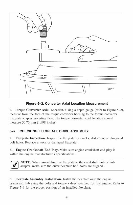
i. Torque Converter Axial Location. Using a depth gauge (refer to Figure 5–2),measure from the face of the torque converter housing to the torque converterflexplate adapter mounting face. The torque converter axial location shouldmeasure 50.76 mm (1.998 inches)
5–2. CHECKING FLEXPLATE DRIVE ASSEMBLY
a. Flexplate Inspection. Inspect the flexplate for cracks, distortion, or elongatedbolt holes. Replace a worn or damaged flexplate.
b. Engine Crankshaft End Play. Make sure engine crankshaft end play iswithin the engine manufacturer’s specifications.
NOTE: When assembling the flexplate to the crankshaft hub or hubadapter, make sure the outer flexplate bolt holes are aligned.
c. Flexplate Assembly Installation. Install the flexplate onto the enginecrankshaft hub using the bolts and torque values specified for that engine. Refer toFigure 5–1 for the proper position of an installed flexplate.
V01717
Figure 5–2. Converter Axial Location Measurement
44

5–3. CHASSIS AND DRIVELINE INSPECTION
Inspect the chassis and driveline components for the following conditions andcorrect them as appropriate.
• Transmission mounts—broken or worn-out
• Bolts and other hardware—damaged, missing, or incorrect
• Isolators (rubber mounts)—damaged or missing
• Driveline angles—runout, or balance which does not conform to themanufacturer’s recommendations
• Driveline yoke slip joints:
— Freedom of movement
— Damaged or worn-out
— Correctly lubricated
— Correctly indexed
• Driveline midship or hanger bearings—damaged or misaligned.
• Universal joints:
— Freedom of movement
— Damaged or worn-out
— Correctly lubricated
— Correctly indexed
CRANKSHAFTHUB ADAPTER
WEAR PLATE
TRANSMISSION
FLEXPLATEADAPTER
ENGINE
V00533.04.00
FLYWHEELHOUSING
BALL BEARINGFLEXPLATEASSEMBLYSEALRING
Figure 5–3. Arrangement of Adaptation Components
45

• Vehicle differential backlash—manufacturer’s specification
• Universal joint coupling—alignment and differential damage
• Cross-frame members and rear support members—condition and location
• PTO-driven equipment shafts and couplings—damaged or misaligned
• Auxiliary transmission:
— Shaft alignment
— Alignment of yoke
— Backlash
— Fluid leaks
5–4. COOLER, FILTER, AND LINES
a. Inspection. Perform the following and correct any faulty conditions:
• Transmission fluid cooler and related coolant lines:
— Check for contamination—clean and flush as necessary
— Inspect for deterioration
— Inspect for faulty connectors or kinks
— Clean and flush transmission fluid cooler, both coolant and oil sides.Pressure check both sides using a 276 kPa (40 psi) air supply.
• Hydraulic lines:
— Inspect for contamination—clean and flush as necessary
— Inspect for deterioration
— Inspect for faulty connectors or kinks
b. After Overhaul. A complete cleanup of the transmission system after anoverhaul cannot be assumed. Repeated cleaning and flushing may not remove alldebris from the transmission fluid cooler system. Replace the transmission “fromcooler” (lube) filter after 8000 km (5000 miles). Refill the transmission to thecorrect fluid level (refer to Section 2–3, TRANSMISSION FLUID CHECK).
5–5. CHECKING CONTROLS
a. Inspection. Inspect the following and correct any faulty conditions:
• Shift selector:
— Improper operation
— Poor electrical connections
— Improper harness routing
46

• Cab and chassis wiring harness:
— Poor electrical connections
— Frayed insulation
— Wiring damage
• Throttle sensor components, if present:
— Freedom of movement
— Improper routing
— Bellows damage
— Improper or loose cable mounting
• PTO controls:
— Damage
— Wear
— Improper operation
— Lubrication
— Electrical harness connections and wiring damage
• Scavenge pump:
— Damage
— Wear
— Improper operation
— Lubrication
• Temperature gauge:
— Capillary tube damage (if used)
— Sensor damage
• Fluid pressure gauge tubing:
— Damage
— Kinks
— Improper routing
b. Throttle Position Sensor (TPS) Adjustment—Using Diagnostic Tool. Whenproperly installed by the equipment manufacturer, the TPS should not requireadjustment. Confirm that the throttle sensor has been installed to manufacturer’sspecifications (refer to Figure 5–5) before adjusting the throttle position sensor.The idle position should be approximately 8.9 mm or 0.97 volts or higher, and fullthrottle position should be approximately 35.7 mm or 3.889 volts or lower. TheTPS is self-calibrating, meaning there is no optimum closed position or wide open
47

position. As long as the travel is within 8.5–35.7 mm range the TPS is setproperly. A total stroke of 15.2–22.9 mm, must be maintained.
Watch the TPS movements as the controls move it through a full stroke. Be surethe following conditions do not exist:
• Misalignment or obstruction to smooth movement through the full stroke.
• Idle and full throttle positions are not within an error zone (refer to Figure5–4).
Error codes occur if the idle position is less than 2.5 mm, or when the full throttleposition is more than 40.6 mm.When idle or wide open throttle positions are inthe error zones, the TCM will log a code. When a TPS code is logged, the TCMassumes a default throttle setting which will negatively effect shift quality.
c. Hitch-Pin Throttle Position Sensor Installation.
1. Install the throttle sensor body as follows:
a. Clamp cable end using clamp and shims (refer to Figure 5–5).
b. Secure the sensor body using the mounting holes provided.
c. Install a heat shield if any part of the throttle sensor is near the exhaustmanifold, turbochargers, or any other heat source.
0 Volt
0.278 Volts
0.972 Volts
CLOSEDTHROTTLE
WIDE OPENTHROTTLE
4.444 Volts
5 Volts
3.889 VoltsAPPROX.
19 mm (0.75 in.) STROKE
FULLYEXTENDED
ERRORZONE
ERRORZONE
FULLYRETRACTED
(AT REST) Total StrokeCT–WOT
15.2 mm–22.9 mm(0.60 in.–0.9 in.)
1.667–2.500 Volts
Adjust so total stroke is within8.9 mm – 35.7 mm band0.97 volts – 3.889 volts
0 mm
2.5 mm(0.1 in.)
8.9 mm(0.35 in.)
40.6 mm(1.6 in.)
35.7 mm(1.4 in.)
45.7 mm(1.8 in.)
V05746.00.02
Figure 5–4. Throttle Position Determination Diagram
48

Fuel lever attachment linkage or bracket mustallow fuel lever to return to closed throttle position
when sensor rod is maintained at full throttle position.Attach the throttle sensor directly to the engine fuel
lever with no breakover or yield linkages between theengine fuel lever shaft and the attachment point of the
throttle sensor.
MOUNTING PROVISION:Use M6 x 1.00 or 1⁄4-20 in. series bolts 3 places
Torque M6 x 1.00 bolt to 10–13 N•m (84–120 lb in.)Torque 1⁄4-20 in. series bolts to 13–14 N•m (108–132 lb in.)
Mount to a solid frame member. Flatness ofchassis mounting surface must not exceed
0.8 mm (0.03 in.).
R 152.0 mm (6.00 in.) MINALLOWANCE RADIUS
FULLYRETRACTED
FULL THROTTLE118.1 mm (4.65 in.)
30.2 mm (1.19 in.)
55.0 mm (2.17 in.)MIN REQUIRED
FOR CONNECTIONREMOVAL
WIRING HARNESS
OPERATING BAND 15.2 – 22.9 mm (0.6 – 0.9 in.)
47.5 mm (1.87 in.)
118.1 mm(4.65 in.)95.2 mm(3.75 in.)
93.45 mm (3.679 in.)87.15 mm (3.431 in.)
HITCH PIN CLIP
ENGINE FUEL LEVER
Attach to engine or governorhousing using clamp and shims asrequired. Clamp must positivelylock in cable groove.
FULLY EXTENDEDFORCE REQUIRED
26.7 N (6.0 LB) MAX
Fuel control must not movethe throttle sensor beyond
the closed throttle positionat any time.
The location of theclamping bracket relativeto the fuel lever at closedthrottle must be maintainedwithin this range.
(NOTE: Mounting length+ 50.8 mm (2 inches) equalscable length)
CLOSED THROTTLE95.2 mm (3.75 in.)
MOUNTINGLENGTH
BENDING LOADAPPLIED
UNACCEPTABLE INSTALLATION
Attachment must provide freedomof motion to allow cable loading intension only (no bending loads).
ACCEPTABLE INSTALLATION
10.0° MAX INSTALLED OPERATING ANGLE IN ALL DIRECTIONS
LOADING INTENSION ONLY
V00430.06
HITCH PIN CLIP
38.1 mm (1.50 in.)
FULLY RETRACTED
FULLY EXTENDED
CLOSED THROTTLE 183.1 mm (7.21 in.) MAX
FULL THROTTLE
SAME AS WITHOUTSLIP LINK
OPTIONAL THROTTLE SENSOR ASSEMBLY WITH SLIP LINK
160.2 mm (6.31 in.) MIN
Figure 5–5. Hitch-Pin Throttle Position Sensor Installation Diagram
49

2. Adjust the throttle sensor as follows:
a. The engine fuel lever must be at the closed throttle position.
b. Install the hitch pin cable end of the sensor to the engine fuel leverwith brackets so that at the idle position the cable end is 11–17 mm(0.44–0.67 inch) from its fully retracted position, and at wide open throttlethe cable end is pulled 15.2–22.9 mm (0.60–0.90 inch) from the idleposition.
c. Check the stroke distance of the throttle sensor, from closed to wideopen. Stroke distance must be from 15.2–22.9 mm (0.60–0.90 inch).
d. Recheck for zero clearance at the fuel lever. Make sure that the15.2–22.9 mm (0.60–0.90 inch) dimension has not changed.
e. Design throttle sensor linkage brackets and levers to nominaldimensions so that the system stays within tolerance bands throughout itsoperating life.
NOTE: The throttle position signal may be provided via communicationlink on electronically controlled engines.
50
6–1. HANDLING
a. Preventing Damage. Handle the transmission carefully to prevent damage tocomponents in the installation path.
b. Control of Transmission Movements. Use a hoist or transmission jack thatallows precise control of transmission movements during installation.
6–2. MOUNTING TO ENGINE
Use the following procedure to mount the transmission to the engine:
1. Align one of the flexplate’s bolt holes with the access opening in theengine flywheel housing.
2. Lubricate the center pilot boss with molybdenum disulfide grease(Molycote G, or equivalent).
3. Install a headless guide bolt into one of the flexplate bolt holes in theflexplate adapter or torque converter mounting lug (refer to Figure 5–1).Align the guide bolt with the flexplate hole at the access opening.
4. Push the transmission toward the engine while guiding the pilot boss on thetorque converter into the flexplate hub adapter and the guide bolt into thehole on the flexplate.
5. Seat the transmission squarely against the engine flywheel housing—noforce is required. If interference is encountered, move the transmissionaway from the engine and investigate the cause.
6. Align the bolt holes in the converter housing with those in the engineflywheel housing.
7. Install all transmission-to-engine bolts finger tight.
CAUTION: The entire converter housing circumference must be flushagainst the engine flywheel housing before tightening any bolts. DONOT use the bolts to seat the housing.
INSTALLINGTRANSMISSION INTO
VEHICLESection VI
51
8. Tighten four bolts at equally-spaced intervals around the converter housingbolt circle. Use the torque specified by the engine or vehiclemanufacturer—usually M10 x 1.5-6H bolts tightened to 51–61 N•m(38–45 lb ft) or 7/16-14 bolts tightened to 73–88 N•m (54–65 lb ft) or3/8-16 bolts tightened to 49–58 N•m (36–43 lb ft).
9. Remove the flexplate guide bolt through the engine flywheel housing accessopening. Replace it with a self-locking bolt. Tighten the bolt finger tight.
NOTE: DO NOT tighten any flexplate-to-flexplate adapter bolts until allof the bolts have been installed and tightened finger tight.
10. Rotate the engine crankshaft to install the remaining self-locking bolts intothe flexplate adapter. After all bolts have been installed finger tight,tighten them to 63–73 N•m (46–54 lb ft).
11. Install the flywheel housing access cover, if used.
6–3. INSTALLING TRANSMISSION MOUNTING COMPONENTS
CAUTION: Use the type and grade of mounting bolts recommended bythe vehicle manufacturer.
1. Install all bolts, washers, spacer, isolators, or supports required to supportthe transmission in the vehicle frame.
2. Tighten the bolts to the torque values recommended by the vehiclemanufacturer.
6–4. COUPLING TO DRIVELINE1. Couple the driveline companion flange or universal joint yoke to the yoke
on the transmission. Use the bolts and torque values recommended by thevehicle manufacturer.
2. Check the universal joint angularity of all U-joints in the driveline.Determine if they are within specification.
6–5. CONNECTING POWER TAKEOFF CONTROLS
If not already mounted, mount the PTO(s) onto the transmission (refer to Section4–3, INSTALLING PTO).
1. Check the PTO harness routing for kinks and sharp bends. Avoid routingthe cable close to exhaust pipes or manifold. The PTO harness must not rubor interfere with adjacent parts.
2. Connect controls to the PTO.
52

3. Check for proper PTO control operation.
CAUTION: PTO units using transmission main pressure to engage thePTO gear must have a positive main pressure shut-off at the solenoidvalve when the PTO is not engaged. Failure to provide this feature maycause inadvertent clutch apply and PTO damage.
4. Couple the PTO output to its driven equipment. Check couplings oruniversal joints for correct assembly and alignment. If the drivencomponent is not a direct mount arrangement, check the PTO drivelines forangularity, phasing, and offsets.
6–6. CONNECTING COOLER
Refer to Figure 6–1 for typical cooler port locations on the transmission andrecommended torque for cooler line fittings.
COOLERRETURN
TORQUE ON COOLER FITTINGS 54–68 N•m (40–50 LB FT)RIGHT VIEW
V01729.00.01
TOCOOLER
Figure 6–1. Torque Values of Typical Fluid Cooler Lines
53

6–7. CONNECTING ELECTRICAL COMPONENTS
NOTE: Allison Transmission electronic control systems are designedand manufactured to comply with all FCC and other guidelinesregarding radio frequency interference/electromagnetic interference(RFI/EMI) for transportation electronics. Manufacturers, assemblers, andinstallers of radio-telephone or other two-way communication radioshave the sole responsibility to correctly install and integrate thosedevices into Allison Transmission-equipped vehicles to customersatisfaction. For further information, refer to TS3989EN, the Allison 4th
Generation Controls Troubleshooting Manual.
1. Remove the cover from the transmission feedthrough connector andcarefully connect the transmission external wiring harness to the 20-waytransmission feedthrough connector. Keep dirt and debris out of theconnector. Tighten the bolt to 2.0–3.2 N•m (18–28 lb inch)
2. Connect the external wiring harness.
a. Connect the engine speed sensor and transfer case connector.
3. Connect the PTO(s) connector(s). The PTO connector is NOT part of theAllison Transmission external wiring harness.
4. Verify the speed sensors, the PTO connector, and other connections aresecurely seated and latched by pulling on the connector—NOT THEWIRES.
5. The transmission has a sump fluid temperature sensor on the internal wiringharness. Actual temperature readings can be made with the diagnostic tool.
6. A temperature gauge may be installed in the “To Cooler” line. If equippedfor them, install a temperature probe—capillary tube and bulb orthermocouple.
7. If equipped with a capillary tube and bulb:
a. Tightened the adapter tight enough to prevent leakage.
b. Install the bulb into the adapter and tighten the nut.
c. Check the capillary tube for interference with other parts that mightchafe or damage the tube.
8. If equipped with a thermocouple:
a. Long tubes may require support clips or brackets.
b. Install the thermocouple and connect the leads.
54

9. Install and connect other electrical components—such as heaters.
a. If equipped, install the pressure gauge tube or line.
b. Check that all unused hydraulic openings are plugged.
6–8. CONNECTING SPEEDOMETER DRIVE
The TCM, through the VIM, provides an electronic speedometer speed signal. Ifused, consult the OEM for connection procedures.
6–9. FILLING HYDRAULIC SYSTEM1. Select a transmission fluid—refer to Section 2–5, FLUID
RECOMMENDATIONS.
2. Fill the transmission with the required amount of fluid—refer to Table 2–4.
3. Run the engine for about one minute and check the fluid level—refer toSection 2–3, TRANSMISSION FLUID CHECK, Paragraph c. Hot CheckProcedure.
6–10. INSTALLATION CHECKLIST
Complete the Installation Checklist. Refer to Section 7.
55
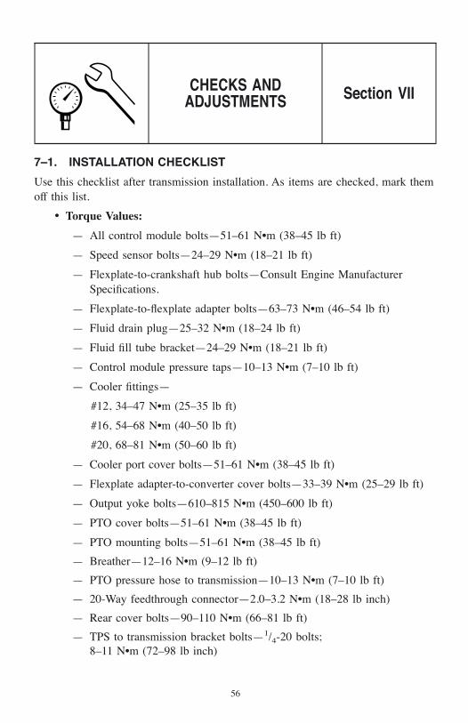
7–1. INSTALLATION CHECKLIST
Use this checklist after transmission installation. As items are checked, mark themoff this list.
• Torque Values:
— All control module bolts—51–61 N•m (38–45 lb ft)
— Speed sensor bolts—24–29 N•m (18–21 lb ft)
— Flexplate-to-crankshaft hub bolts—Consult Engine ManufacturerSpecifications.
— Flexplate-to-flexplate adapter bolts—63–73 N•m (46–54 lb ft)
— Fluid drain plug—25–32 N•m (18–24 lb ft)
— Fluid fill tube bracket—24–29 N•m (18–21 lb ft)
— Control module pressure taps—10–13 N•m (7–10 lb ft)
— Cooler fittings—
#12, 34–47 N•m (25–35 lb ft)
#16, 54–68 N•m (40–50 lb ft)
#20, 68–81 N•m (50–60 lb ft)
— Cooler port cover bolts—51–61 N•m (38–45 lb ft)
— Flexplate adapter-to-converter cover bolts—33–39 N•m (25–29 lb ft)
— Output yoke bolts—610–815 N•m (450–600 lb ft)
— PTO cover bolts—51–61 N•m (38–45 lb ft)
— PTO mounting bolts—51–61 N•m (38–45 lb ft)
— Breather—12–16 N•m (9–12 lb ft)
— PTO pressure hose to transmission—10–13 N•m (7–10 lb ft)
— 20-Way feedthrough connector—2.0–3.2 N•m (18–28 lb inch)
— Rear cover bolts—90–110 N•m (66–81 lb ft)
— TPS to transmission bracket bolts—1/4-20 bolts;8–11 N•m (72–98 lb inch)
CHECKS ANDADJUSTMENTS Section VII
56
• Cooler Fluid Lines and Air Hose for:
— No leaks
— Connection tightness
— Correct routing
• Throttle sensor for:
— Proper adjustment
— Correct routing of cable and harness
• Driveline for:
— Proper indexing of universal joints
— Proper drive shaft angles
— Driveline backlash
— Lubricated universals and slip-joints
• Hydraulic System for:
— Recommended fluid—TranSynd™ or DEXRON®-III
— Correct fluid level in transmission
— Dipstick correctly calibrated—Refer to Figure 2–1
— Fill tube tight
— Fill tube cap tight
— Breather clean and free of restrictions
— No fluid leaks during operation
• Instruments and Electrical Equipment for:
— Proper wiring and electrical connections
— Instruments, gauges, and lights work correctly
— Shift Selector display is on and CHECK TRANS light is off
— Fluid temperature gauge
• Power Takeoff for:
— Controls connected and operative
— Correctly coupled to driven equipment
— Lubrication line correctly installed and routed—if used
57

7–2. ROAD TEST AND VEHICLE OPERATION CHECKLIST
a. Driveability.
NOTE: Refer to the latest edition of the 3000 Product FamilyOperator’s Manual or Owner’s Manual for operating instructions. Referto Section 8–1 for the latest publication number.
Drive-away checks are performed to verify proper transmission and supportequipment installation and operation. The following steps outline drive-awaycheck procedures:
1. Check fluid—fill the transmission with the appropriate fluid.
2. Start the vehicle—check for proper system response during start-up.
a. Turn on the vehicle’s master/ignition switch.
b. The CHECK TRANS light should come on.
c. Start the engine
d. The CHECK TRANS light should go off.
e. “NN” should appear in the shift selector display.
3. Clear Trouble Codes—during installation, it is common for “false” codes tobe stored in the electronic control’s TCM. These codes must be clearedprior to road testing the vehicle.
4. Road Test the Vehicle—allow the electronic control time to “converge”shifts.
5. Check for Proper Operation—check all components for proper mountingand operation, and check for transmission fluid leaks at gasket surfaces,lines, and hoses.
6. Recheck for Trouble Codes—use the Allison DOC™ or the shift selector todetermine if codes were set during the road test. Refer to Section 2–11.
7. Troubleshoot—if codes exist after the road test, problems must be foundand corrected (refer to TS3989EN, Allison 4th Generations ControlsTroubleshooting Manual).
b. Service and Maintenance. Refer to the current issue of the 3000 ProductFamily Service Manuals for detailed transmission service and maintenanceinstructions. Refer to the latest issue of the Allison 4th Generation ControlsTroubleshooting Manual for detailed electronic control system troubleshooting.Refer to Table 8–1 for the latest publication number.
58

c. Road Test Checklist. Complete the following checklist.
• Neutral Start Circuit::
— Starts only in N (Neutral)
• Instruments:
— CHECK TRANS light and shift selector display
— Transmission fluid pressure gauge—if used
— Speedometer
— Temperature gauge—if used
— Reverse warning system—if used
• Transmission Fluid:
— Fluid level meets specifications—cold, neutral, level
— No leaks
— Warm up and verify fluid level—hot, neutral, level
• No-Load Governed Engine Speed:
— No-load governed speed of engine
— Adjust governor as necessary—refer to the manufacturer’sspecifications for the engine-transmission being tested
• PTO:
— PTO operation Refer to the appropriate Operator’s Manual. Refer toTable 8–1 for the latest publication number
• Shift Sequence:
— Transmission upshifts and downshifts smoothly through all ranges
• Other Checks:
— Stall test
— Shift quality
• Comments:
__________________________________________
__________________________________________
__________________________________________
__________________________________________
__________________________________________
59
8–1. OWNER ASSISTANCE
There are distributors and dealers around the world ready to stand behind everyAllison Transmission product. Any situation that arises in connection with thesale, operation, or service of your transmission will be handled by the distributoror dealer in your area.
Refer to the Worldwide Sales and Service Directory SA2229EN for a currentlisting of Allison Transmission authorized distributors and service dealers.
8–2. SERVICE LITERATURE
Additional service literature is available as shown in the following table. Thisservice literature provides fully illustrated instructions for the operation,maintenance, service, overhaul, and parts support of your transmission. To be surethat you get maximum performance and service life from your transmission, youmay order publications from:
SGI Inc.Attn: Allison Literature Fulfillment Desk8350 Allison AvenueIndianapolis, IN 46268TOLL FREE: 888–666–5799INTERNATIONAL: 317–471–4995
CUSTOMER SERVICE Section VIII
60

Table 8–1. 3700 SP Service Literature
Publication Title Publication NumberAutomatic Transmission Fluid Technician’s Guide GN2055ENOperator’s Manual* MT4108ENMechanic’s Tips* OM3753ENParts Catalog* PC2150ENParts Catalog CD-ROM CD2150ENPrinciples of Operation PO4016ENService Manual** SM4013ENElectronic Troubleshooting Manual TS3989ENAllison DOC™ for PC–Service Tool User Guide GN3433ENWorldwide Sales and Service Directory* SA2229EN*Also Available On The Internet At www.allisontransmission.com**Available 4th Quarter 2005
61

MT4108EN 200509 Printed in USA 200509www.allisontransmission.com
C
M
Y
CM
MY
CY
CMY
K
MT4108 back.pdf 9/21/05 1:40:26 PMMT4108 back.pdf 9/21/05 1:40:26 PM


