Yarway 7100 Series ArC® Automatic recirculation Control valve for all valves Serial no. A71230 and below.
engineering doc. #968155 rev. d
INstallatION
General instructions1. look at typical installation diagram
(see figure 1).2. Valve can be installed in any position.
However, flow arrow on body must match flow direction in pipe.
3. Valve body material is either carbon steel (ASMe-SA 216 WCB) or stainless steel (ASMe SA351 Cf8M).
look at the valve nameplate - it will identify the material for your valve!
4. When welding valve in line, select compatible weld rod and follow all applicable codes and regulations.
5. follow recommendations on installation diagram (opposite page) for straight pipe, maintenance clearances and auxiliary valve locations. refer to 'iSA handbook of control valves' Chapter 12 for other recommended installation practices.
CautION!The valve you are about to install contains elastomer seals. If welding the valve in line, do one of two things;
OpEratION
CautION!There are only two adjustments described in the following notes, which can be made to an installed and operating valve. Your valve has been preset and tested at the factory for your conditions. Adjustments are necessary only when conditions change and are not to be made before contacting a Yarway application engineer to determine how much adjustment, if any, is necessary. Making adjustments on your own can cause serious damage to the pump and system.
1. the 7100 Series valve is a self-contained, fully automatic device which requires no external power or signals to perform its function.
2. the valve does two things: (1) it protects the pump from reverse flow, and (2) prevents the pump from overheating during low load periods.
3. Your valve has a modulating bypass. the bypass will open or close gradually so that the sum of main flow and bypass flow will never be below the minimum flow requirement of the pump.
4. if operating conditions should change, two adjustments can be made in the valve (within limits). they are:
a. Switchpoint. b. Bypass capacity. Switchpoint is the main flow quantity at
which the bypass will open or close. Bypass capacity is the flow quantity that
will pass through the bypass.
either:1. Keep the main body of valve below 300°F
during preheat, welding and post weld heat treatment.
OR2. Disassemble the valve to remove seal
containing parts (refer to Maintenance section for procedures - disc/bonnet removal and bypass bushing cartridge removal).
Note: failure to follow these precautions will result in damaged seals!
2
A
A
l3l2l1
g
f
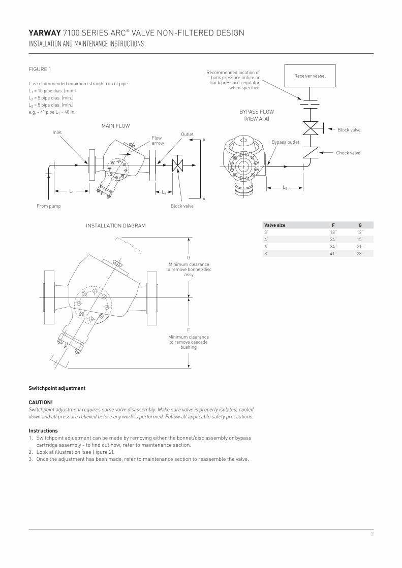
3” 18” 12”4” 24” 15”6” 34” 21”8” 41” 28”
YarwaY 7100 SerieS ArC® VAlVe non-filtered deSignInstallatIon and maIntenance InstructIons
Block valve
recommended location of back pressure orifice or back pressure regulator
when specifiedl is recommended minimum straight run of pipel1 = 10 pipe dias. (min.)l2 = 5 pipe dias. (min.)l3 = 5 pipe dias. (min.)e.g. - 4” pipe l1 = 40 in.
Block valvefrom pump
inlet outletBypass outlet
flow arrow
receiver vessel
Check valve
MAin floW
BYpASS floW(VieW A-A)
Valve size F G
figure 1
Minimum clearance to remove bonnet/disc
assy
Minimum clearance to remove cascade
bushing
inStAllAtion diAgrAM
switchpoint adjustment
CautION!Switchpoint adjustment requires some valve disassembly. Make sure valve is properly isolated, cooled down and all pressure relieved before any work is performed. Follow all applicable safety precautions.
Instructions1. Switchpoint adjustment can be made by removing either the bonnet/disc assembly or bypass
cartridge assembly - to find out how, refer to maintenance section.2. look at illustration (see figure 2).3. once the adjustment has been made, refer to maintenance section to reassemble the valve.
3
YarwaY 7100 SerieS ArC® VAlVe non-filtered deSignInstallatIon and maIntenance InstructIons
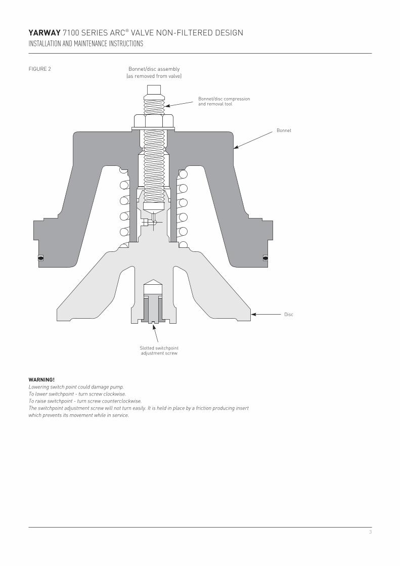
warNING!Lowering switch point could damage pump.To lower switchpoint - turn screw clockwise.To raise switchpoint - turn screw counterclockwise.The switchpoint adjustment screw will not turn easily. It is held in place by a friction producing insert which prevents its movement while in service.
Bonnet/disc assembly(as removed from valve)
Bonnet/disc compression and removal tool
Bonnet
disc
Slotted switchpoint adjustment screw
figure 2
4
YarwaY 7100 SerieS ArC® VAlVe non-filtered deSignInstallatIon and maIntenance InstructIons
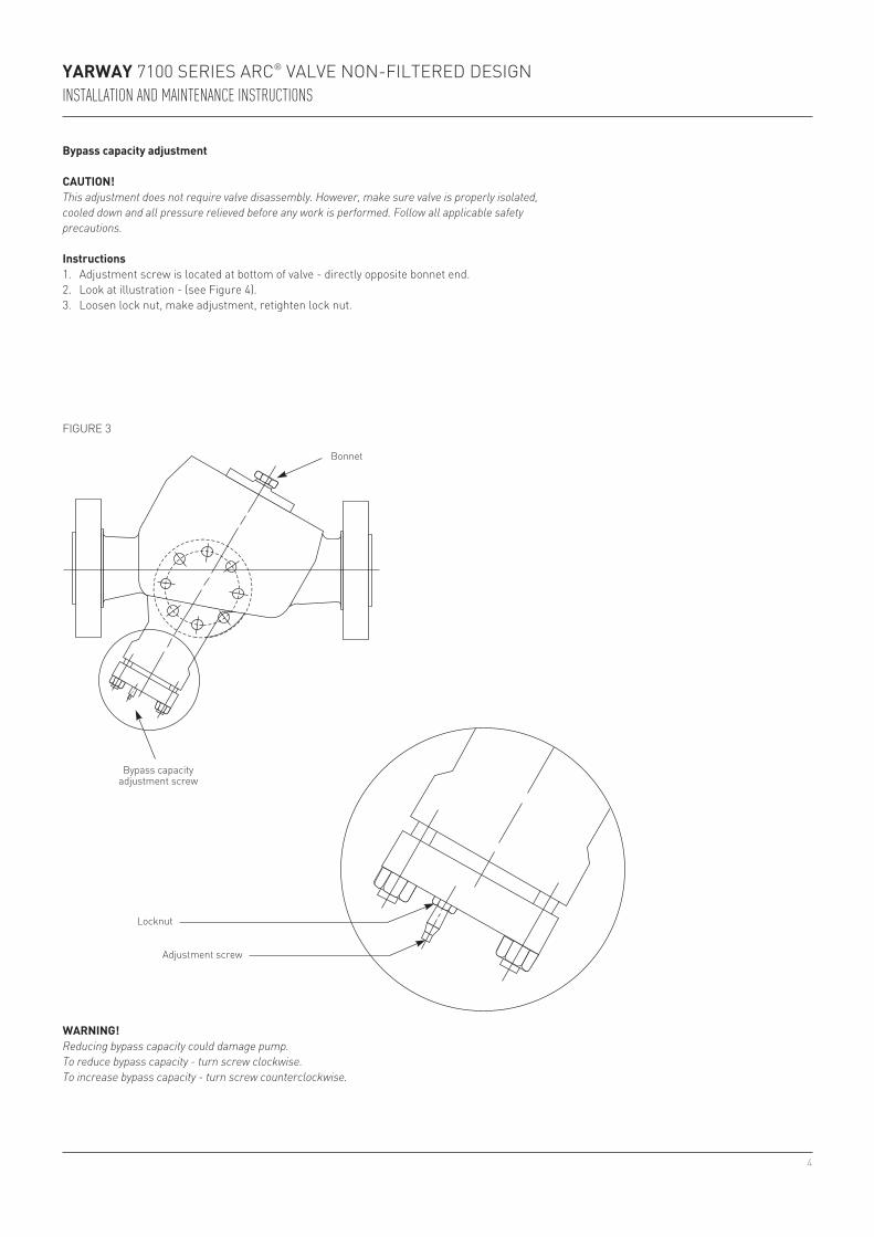
Bypass capacity adjustment
CautION!This adjustment does not require valve disassembly. However, make sure valve is properly isolated, cooled down and all pressure relieved before any work is performed. Follow all applicable safety precautions.
Instructions1. Adjustment screw is located at bottom of valve - directly opposite bonnet end.2. look at illustration - (see figure 4).3. loosen lock nut, make adjustment, retighten lock nut.
YarwaY 7100 SerieS ArC® VAlVe non-filtered deSignInstallatIon and maIntenance InstructIons
General instructions 1. there are only two major disassembly
procedures: a. Bonnet/disc removal. b. Bypass cartridge removal.2. Valve body does not need to be removed
from line to perform any maintenance and service procedures.
3. Slightly damaged seating surfaces can be reconditioned by lapping with a fine lapping compound.
4. When changing lip type seals, make sure they are installed in proper direction or the valve won’t work properly.
MaINtENaNCE
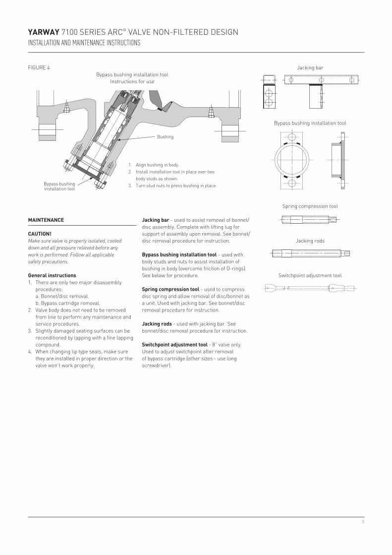
1. Align bushing in body.2. install installation tool in place over two
body studs as shown.3. turn stud nuts to press bushing in place.
Bypass bushing installation toolinstructions for use
Bushing
Bypass bushing installation tool
CautION!Make sure valve is properly isolated, cooled down and all pressure relieved before any work is performed. Follow all applicable safety precautions.
Jacking bar
Bypass bushing installation tool
Spring compression tool
Jacking rods
Switchpoint adjustment tool
Jacking bar - used to assist removal of bonnet/disc assembly. Complete with lifting lug for support of assembly upon removal. See bonnet/disc removal procedure for instruction.
Bypass bushing installation tool - used with body studs and nuts to assist installation of bushing in body (overcome friction of o-rings). See below for procedure.
spring compression tool - used to compress disc spring and allow removal of disc/bonnet as a unit. used with jacking bar. See bonnet/disc removal procedure for instruction.
Jacking rods - used with jacking bar. See bonnet/disc removal procedure for instruction.
switchpoint adjustment tool - 8” valve only. used to adjust switchpoint after removal of bypass cartridge (other sizes - use long screwdriver).
figure 4
6
YarwaY 7100 SerieS ArC® VAlVe non-filtered deSignInstallatIon and maIntenance InstructIons
Bonnet/disc assembly parts identification
Bonnet/disc removal/installation
Bonnet
Spring
disc
pipe plugHoles for
threaded rods
use upper nuts to push bonnet inuse this nut to
compress spring
Compression toolJacking rod
Jacking bar
use lower nuts to pull bonnet out
Bonnet/disc assembly (shown compressed)
Segmented ring retainer
Segmented ring
figure 5
7
YarwaY 7100 SerieS ArC® VAlVe non-filtered deSignInstallatIon and maIntenance InstructIons
Bonnet/disc removal and assembly
Disassembly1. look at illustration (see figure 5).2. remove pipe plug.3. insert compression tool through the bonnet and screw into disc.4. turn nut until disc is in full up position.5. there are two threaded holes in top of body - use these with jacking rods (can be made from
threaded rod) and jacking bar (can be made from appropriate size angle iron or square tube).6. using jacking bar, push bonnet into body approximately ⅛”.7. remove segmented ring retainer.8. remove segmented rings.9. using jacking bar, pull bonnet/disc assembly out of valve.
assembly1. Bonnet and disc must be installed as a unit - use compression tool to assemble
bonnet/spring/disc.2. using jacking bar, push bonnet/disc assembly into valve until it stops.3. insert segmented rings.4. install segmented ring retainer.5. using jacking bar, pull bonnet/disc assembly until it is snug against segmented rings.6. With compression tool in place, turn nut until disc is lowered onto seat, then remove tool
from bonnet.7. replace pipe plug.
8
See detail A
new design has large groove
o-ring
Back-up ring
Valve body
Bypass bushing
Bushing orientation spring pin
Bypass cover
Bypass capacity adjustment screw
Bypass
Adjustment screw cover
retainer
pilot tube
piston
Bypass bushing
threaded holes for jack screws
threaded holes for jack screws
Bypass cover
Anti-rotations keys
pilot valve seat
pilot tube seal bushing
retaining ring
retainer
pilot tube
piston
Bypass bushing
Bypass cover
Anti-rotations keys
pilot valve seat
pilot tube seal bushing
piston
3” VAlVe onlY(new design)
KeY
detAil A
detAil CConical seat pilot tube design
(new design)
detAil dSpherical seat pilot tube design
(old design)
See detail C or d below
Metering orifice
Metering orifice retainer
pilot tube
YarwaY 7100 SerieS ArC® VAlVe non-filtered deSignInstallatIon and maIntenance InstructIons
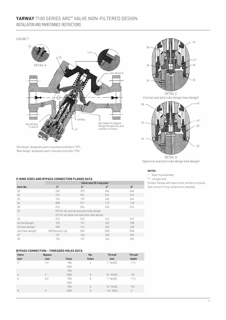
'old design' designates parts manufactured before 1997; 'new design' designates parts manufactured after 1996.
figure 6
9
YarwaY 7100 SerieS ArC® VAlVe non-filtered deSignInstallatIon and maIntenance InstructIons
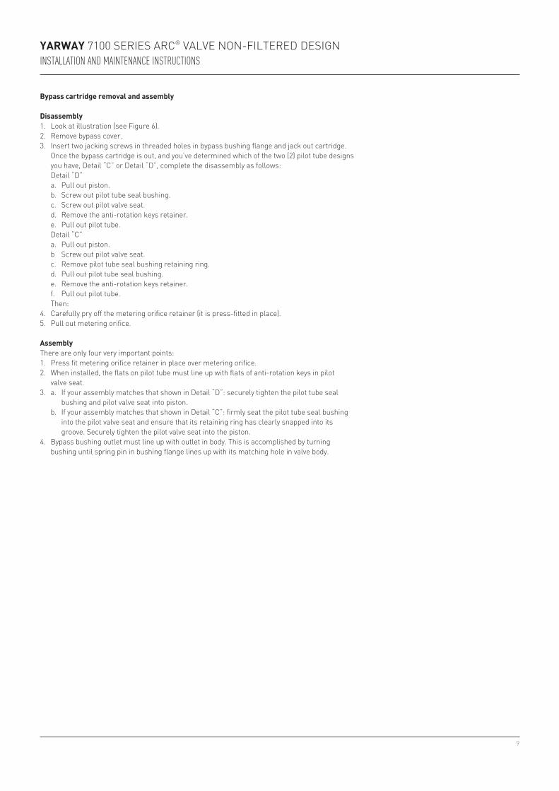
Bypass cartridge removal and assembly
Disassembly1. look at illustration (see figure 6).2. remove bypass cover.3. insert two jacking screws in threaded holes in bypass bushing flange and jack out cartridge. once the bypass cartridge is out, and you’ve determined which of the two (2) pilot tube designs
you have, detail “C” or detail “d”, complete the disassembly as follows: detail “d” a. pull out piston. b. Screw out pilot tube seal bushing. c. Screw out pilot valve seat. d. remove the anti-rotation keys retainer. e. pull out pilot tube. detail “C” a. pull out piston. b Screw out pilot valve seat. c. remove pilot tube seal bushing retaining ring. d. pull out pilot tube seal bushing. e. remove the anti-rotation keys retainer. f. pull out pilot tube. then:4. Carefully pry off the metering orifice retainer (it is press-fitted in place).5. pull out metering orifice.
assemblythere are only four very important points:1. press fit metering orifice retainer in place over metering orifice.2. When installed, the flats on pilot tube must line up with flats of anti-rotation keys in pilot
valve seat.3. a. if your assembly matches that shown in detail “d”: securely tighten the pilot tube seal
bushing and pilot valve seat into piston. b. if your assembly matches that shown in detail “C”: firmly seat the pilot tube seal bushing
into the pilot valve seat and ensure that its retaining ring has clearly snapped into its groove. Securely tighten the pilot valve seat into the piston.
4. Bypass bushing outlet must line up with outlet in body. this is accomplished by turning bushing until spring pin in bushing flange lines up with its matching hole in valve body.
012 for all spherical seat pilot tube design43 012 012 012 01246 (old design) 125 141 232 23846 (new design) 028 141 232 23846a (new design) 028 Backup ring n/A n/A n/A47 131 146 242 35448 133 147 244 356
BYpass CONNECtION – thrEaDED hOlEs DataValve size
Bypass size Class
No. holes
thread size
thread depth
11
46/46a
47
18
19
31
51*
51*
1
17
50/49 7 33 4 8 6
3 2 5
51
30
48
24
15
27
52
32
53 26 29
15
34
34
23
23
22
14
12
13
13
11 10 9 7
58
12
14
22
24
YarwaY 7100 SerieS ArC® VAlVe non-filtered deSignInstallatIon and maIntenance InstructIons
See detail e
See details C and d
See details A and B
detAil A(new design)
detAil e
detAil B(old design)
o-ring
Back-up ring
3” VAlVe onlY(new design)
figure 8
12
42
43
22
19
41
48
45
35
38
44
39
28
36
27
44
39
45
60
YarwaY 7100 SerieS ArC® VAlVe non-filtered deSignInstallatIon and maIntenance InstructIons
detAil dSpherical seat pilot tube design
(old design)
detAil CConical seat pilot tube design
(new design)
'old design' designates parts manufactured before 1997; 'new design' designates parts manufactured after 1996.
NOtEs* recommended spare parts for service and inspection.∙ recommended spare parts for service overhaul.♦ optional on body.❖ Must be replaced as a set for the first disc replacement made after 1996.
parts lIstItem Description Item Description1 Body 30 Bypass cover2 Bonnet 31 Stud3 pipe plug 32 nut4 Segmented retaining ring 33∙* o-ring5 Segmented ring retainer 34∙* o-ring6 Spring 35∙* o-ring7❖ disc 36∙* o-ring8 orifice snubber 38∙* o-ring9 retaining ring 39∙* o-ring10 Washer 41∙* Seal assembly11∙* Seal 42∙* Anti-rotation keys12❖ disc lower guide bushing 43∙* retainer (o-ring)13 Switch point adjustment screw 44∙* pilot valve seat14 Switch point adjustment screw bushing 45∙ pilot tube seal bushing15 Spring pin 46∙* o-ring17 flow element 46a∙* Back-up ring (3” valve only - new design)18∙ Bypass bushing 47∙* o-ring19∙ piston 48∙ o-ring22∙* pilot tube 49 drive screws23∙* Metering orifice 50 nameplate24∙* Metering orifice retainer 51♦ pipe plug26 Spring pin 52 Stud27 Stroke adjustment screw 53 Adjustment screw cover28 Spring pin 58❖ retaining ring29 lock nut 60 retaining ring