YIAMT-421 Y-12 Final CRADA Report for CRADA Number Y-1296-0426 ADVANCED HARDWARE AND SOFTWARE METHODS FOR THREAD AND GEAR DIMENSIONAL METROLOGY A. C. Miller, Jr. E. B. Grann Lockheed Martin Energy Systems, Inc. Sean Smith Apeiron, Inc. March 5, 1997 Approved for Public Release; distribution is unlimited. LOC w Prepared by the Oak Ridge Y-12 Plant managed by for the U.S. DEPARTMENT OF ENERGY under contract DE-AC05-840R21400 KHEED MARTIN ENERGY SYSTEMS, INC
Transcript
YIAMT-421
Y-12 Final CRADA Report
for CRADA Number Y-1296-0426
ADVANCED HARDWARE AND SOFTWARE METHODS FOR THREAD AND GEAR DIMENSIONAL METROLOGY
A. C. Miller, Jr. E. B. Grann
Lockheed Martin Energy Systems, Inc. Sean Smith
Apeiron, Inc.
March 5, 1997
Approved for Public Release; distribution is unlimited.
LOC
w
Prepared by the Oak Ridge Y-12 Plant
managed by
for the U.S. DEPARTMENT OF ENERGY
under contract DE-AC05-840R21400
KHEED MARTIN ENERGY SYSTEMS, INC
DISCLAIMER
This report was prepared as an aceount of work sponsored by an agency of the United States Government Neither the United States Government nor any agency thereof, nor any of their employees, make any warranty, express or implied, or assumg any legal liabili- ty or ~esponsi i ty for the accuracy, completeness, or usefulness of any information, appa- ratus, product, or process disdosed, or represents that its use would not infringe privately owned rights. Reference herein to any spec5c commercial product, pmcss, or service by trade name, trademark, manufacturer, or otherwise does not necessarily constitute or imply its endorsement, recommendation, or favoring by the UNted States Government or any agency thereof. The views and opinions of authors expressed herein do not necessar- ily state or reflect those of the United States Government or any agency thereof.
DISCLAIMER
Portions of this document may be illegible electronic image products. Images are produced from the best available original document.
f
Abstract
, The Oak Ridge Centers for Manufacturing Technology (ORCMT) and Apeiron Incorporated have collaborated on an effort to develop a frequency modulated continuous wave (FMCW) fiber lidar system for dimensional metrology of internal threads, gears and splines. The purpose of this effort was to assist a small company in developing an instrument that would exceed the performance of competing foreign instruments and provide measurement capabilities necessary to assure compliance for NASA facilities and other industrial facilities. The two parties collaborated on design, assembly, and bench testing of the prototype instrument. The prototype system was targeted to have the capability of profiling internally machined gears and threads to an accuracy of less than a micron.
Background
This measurement, or metrology, of physical objects is a fundamental requirement for industria1 progress. Dimensional measurement capabilities lie at the heart of our ability to produce objects within the required technical specifications. Increasing performance demands in turn require advances in dimensional system design that can include tighter (smaller) dimensional tolerances. The evolutionary progress of measurement and manufacturing technologies is inextricably 1 inked.
Dimensional metrology systems are presently dominated by touch-probe technologies, which are mature and reliable. Due to the intricate geometries required in certain fields of manufacturing, these contact probes cannot be physically brought in proximity to the measurement surface, or lack sufficient lateral resolution to satisfactorily determine the surface profile, which can occur in the measurement of gears, splines and threads. Optical probes are viable candidates to supplement the contact probes, since light can be focused to less than one micron, no contact occurs that can mar highly finished surfaces, and no probes must be replaced due to wear. However, optical probes typically excel only on one type of surface: mirror-like or diffuse, and the optical stylus itself is oftentimes not as compact as its contact probe counterpart. Optical heterodyning using a FMCW laser radar system is one technique which offers a solution for determining the absolute range off diffuse targets with extremely good resolution and dynamic range.
Prloject Objectives
The objective of this CRADA was to develop a fiber-based coherent ranging system specialized to near-field measurement suitable for use in thread and gear metrology to measure the dirnensional characteristics of external and internal gears, splines, and threads. Specifically, the objectives for both the Contractor and the Participant are listed below.
- Contractor ObiectivedTasks
1) Design a fiber based FMWC lidar system 2) Design and fabricate a micro-optical head for internal gear and thread measurements 3) Demonstrate and test fully-integrated fiber system 4) Jointly prepare the final report summarizing the research findings
- Particiuant Obiectives/Tasks
CRADA Y- 1296-0426 March 5, 1997 Page 1
1) Procure and deliver fiber components 2) Design and fabricate a micro-optical head for internal gear and thread
3) Develop and implement technique for analyzing heterodyne beat signals 4) Demonstrate and test fully-integrated fiber system 5) Jointly prepare the final report summarizing the research findings
measurements
Prqject Results
m i n a l fiber based FMCW lidar system
The original design of a fiber based FMCW lidar system used a Michelson interferometer arrangement for splitting off a reference and target beam and then recombining them for heterodyning at the detector. Each leg of the interferometer was completely contained within a single-mode polarization preserving fiber. Unlike a free-space apparatus, in which each leg of the interferometer propagated through air (n )) 1 .O), the fiber based system propagates through a specific medium. Any slight change in the material characteristics of the fiber, which may be caused by thermal or vibrational stresses, will delay or speed up the signal causing a phase shift in the beat frequency of the heterodyned signal.
Initial experiments with the fiber based lidar system generated far larger phase shifts than anticipated. It was observed that any slight perturbation (Le. breathing on the fiber, touching the fiber, placing hand near the fiber, etc.) to either leg of the interferometer caused an unacceptable phase shift in the beat frequency. The extent of the shift was so great, even with proper fiber isolation, that an alternate approach was pursued to help reduce the sensitivity to environmental conditions.
- Alternative fiber based FMCW lidar system
An alternative approach to the original Michelson arrangement was designed in which both the reference and target signals would propagate within the same fiber. The end of the fiber is used to reflect a portion of the incident signal as a reference, while the target signal exits the fiber, reflects off the object being measured, and is then collected by the same fiber. Any slight change in tlne material characteristics of the fiber would be experienced by both signals, and thus cancel.
Implementation of the alternative approach showed that very little light could be successfully collected from the target back into the fiber to produce a beat signal. The light exiting the fiber must propagate a few centimeters before striking the target. This distance is necessary to provide a time delay for the returning light to establish an appropriate beat frequency. Since this particular single-mode polarization preserving fiber is only 3-4 microns in diameter, it is extremely difficult to collect the reflected light. Therefore, any reflected signals from the target are significantly reduced due to the small fiber and delay distance.
_I Future development efforts: .a free-space FMCW lidar system
Due to the above described technical difficulties, a fiber based system does not appear to be a pralctical technique for implementing a FMCW lidar system. A more attractive solution which is beyond the scope of the present CRADA effort is to design a micro-optical free-space system in
CRADA Y-1296-0426 March 5, 1997 Page 2
which the laser light is delivered via an optical fiber. It will still be necessary to displace the reference arm and the target arm by approximately 2-3 centimeters in order to create a sufficient time delay for establishing the beat frequency.
One of the biggest challenges still remaining is obtaining enough reflected energy from the target object to create a beat frequency which can be detected. Initial experiments produced detectable beat frequency signals from diffuse surfaces at normal incidence. However, for gear and thread mea:surements the target surface is typically at 60 degrees. Also, the surface may be highly specular, causing most of the energy to be reflected away from the collection optics. Experiments using angular surfaces did not produced suitable signals. While this type of lidar system is based on heterodyning of the reference and target signals, detection of a beat frequency is an intensity measurement problem. One recommendation which may eliminate this problem is to increase the power of the laser source.
Another difficulty with the current apparatus is "mode-hopping" of the laser, in which a slight change in the resonance shifts the output wavelength. These discrete steps can cause a drastic phase distortion in the beat frequency. There are two possible reasons for this occurrence. First, any reflected energy which returns to the laser cavity (feedback) will destabilize the laser causing it to change its oscillating mode. This problem can be minimized by placing a high quality optical isolator in front of the laser. Second, if the DC level of the drive current is not set in thLe optimum position, then the ramp current may cause the laser to change modes at a certain current level. A distributed feedback laser can help to minimize this problem.
- Success in Meeting the CRADA Objectives
Several approaches for implementing a fiber based FMCW lidar system for gear and thread measurements have been designed, constructed, and tested. Several signal analysis techniques were also investigated, for which two possible techniques were chosen. However, it is clear that a significant amount of additional development will be necessary to produce a working protlotype. For the purposes of the CRADA; however, important research and development was performed and valuable lessons have been learned.
Benefits to DOE
Accurate dimensional metrology is vital to DOE'S ability to perform its mission with regard to existing and anticipated Defense Programs. While contact probe technologies have been the wor.khorse for dimensional metrology, optical non-contact methods are superior when no contact with the sample can be tolerated (protection of surface finish, static electricity, etc.), when the measurement surface is inaccessible to a contact probe, or when superior lateral resolution with respect to surface features is required. By combining the expertise at the Oak Ridge Center for Metrology with Aperion's innovative thread measurement system, DOE is in a position to influence the development of commercial instruments that will be essential to meet its defense- related mission.
This project is a continuation of a DOE CRADA (Y-12 94-0307) with Aperion and ORCMT. That particular CRADA project was designed to determine the resolution limitations of a laser scanning coordinate measurement system and to identify methods of overcoming those limitations.
CRADA Y-1296-0426 March 5, 1997 Page3
Technical Discussion
- Intiroduction
Gear and thread metrology requires rapid, accurate and compact methods of measuring the prolfile and depth of the finished parts. Several methods already exist to perform metrology on threaded parts and gears, but they have limitations that must be recognized depending on the measurements approach. For instance, active triangulation is a simple method to measure thread profile and depth (this is the method currently used by Apeiron), but it suffers from poor lateral resolution, and can be error-prone when highly-machined surfaces must be measured due to multiple reflection from the specular surfaces that confuse the measurement algorithm. Additionally, the nature of triangulation measurements requires a separation between the illumination and imaging paths to form the triangular geometry. This awkward geometry makes access to internal threads and gears almost impossible, in most cases. Interferometric approaches are not appropriate since the surfaces are not specular enough for high contrast fringe formation. There are grazing-incidence interferometric approaches, but these would not be applicable to the finely corrugated surfaces common in thread measurement. Imaging methods have been considered (such as confocal microscopy) but would require a significant investment in software as well as data acquisition time. Surface profilometers based on auto-focus techniques may have applications for highly-reflective surfaces, but would be useless on diffuse surfaces that may be encountered in machined composites, for example.
We proposed to prototype a gear and thread metrology system based on an all fiber-optic frelquency-modulated continuous wave (FMCW) laser radar using a semiconductor laser. A description of the prototyped system follows in this technical description.
- Ba:sic Theorv of Heterodvne Detection
Heterodyning is the coherent superpositioning of two electromagnetic waves having the same pollarization, but different frequencies. It is also called optical mixing, in analogy with communications theory. If we combine two optical signals on a photodetector that respond to liglht intensity, a sum and difference beat frequency results. To illustrate this concept, let us define two complex amplitudes having different amplitudes, frequencies, and phases, but identical polarization.
E, = a, exp J [ w + A ]
E, = a,, exp J [ W * / + A ]
If we coherently add the two amplitudes, and then find the magnitude (which is proportional to inknsity), the result is:
I ( t ) = IEI +E,I2 = a: + ai + 2a,a, cos[(wl - w2 >t + (4, - 42 >] = a: + ai + 2a,a, cos[ Awt + A#]
and we detect a difference or beat frequency shifted in phase. A sum frequency is also produced, but cannot be detected by the square law detector.
CRADA Y- 1296-0426 March 5 , 1997 Page 4
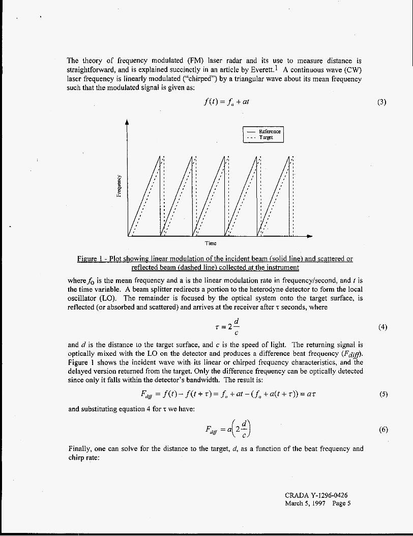
The: theory of frequency modulated (FM) laser radar and its use to measure distance is straightforward, and is explained succinctly in an article by Everett.1 A continuous wave (CW) laser frequency is linearly modulated ("chirped") by a triangular wave about its mean frequency such that the modulated signal is given as:
Time
- Reference 1 - - - Target I
Figure 1 - Plot showing linear modulation of the incident beam (solid line) and scattered or reflected beam (dashed line) collected at the instrument
wheref, is the mean frequency and a is the linear modulation rate in frequency/second, and t is the time variable. A beam splitter redirects a portion to the heterodyne detector to form the local oscillator (LO). The remainder is focused by the optical system onto the target surface, is reflected (or absorbed and scattered) and arrives at the receiver after z seconds, where
d 2 = 2 -
C
and d is the distance to the target surface, and c is the speed of light. The returning signal is optically mixed with the LO on the detector and produces a difference beat frequency (Fd@. Figure 1 shows the incident wave with its linear or chirped frequency characteristics, and the delayed version returned from the target. Only the difference frequency can be optically detected since only it falls within the detector's bandwidth. The result is:
FdN = f ( t ) - f ( t + z) = i) + at - (f, + a(t + z)) = a z
andl substituting equation 4 for z we have:
Finally, one can solve for the distance to the target, d, as a function of the beat frequency and chirp rate:
(4)
CRADA Y-1296-0426 March 5,1997 Page 5
c d=-Fdg
2a For example, from a range of lOcm, if we can chirp the laser at 10GHz/ps, the beat frequency that results is 6.66MHz. To resolve a change in distance of lOpm requires the ability to discriminate the change in frequency to one part in 105, or 666Hz, since Ad / d=AFd@/ F d $ f
- Sensitivitv and Chirp Characteristics
Although most laser diodes can be modulated directly (using a bias-T network commonly used with microwave devices) about a DC setpoint, severe requirements are placed upon the microwave sweep generator in terms of linearity and sweep rate (see Equation 7). If the current of the laser diode is modulated, the laser will change frequency at a value of Av x 2GHz/mA, which is typical for a Fabry-Perot-type (FP) buried heterostructure laser.2,3 Two undesirable side effects occur, however. Firstly, the gain curve of a semiconductor laser is quite broad and there is nothing in the simple FP structure that determines mode selection except the spacing of the cavity mirrors. Therefore, under the effects of current tuning, the laser hops mode to whiitever mode is favored under those conditions of current and temperature. This introduces phase noise and degrades the ranging performance. Secondly, the spectral linewidth of these lasers broadens under current modulation which reduces the coherence length of the device, ultimately limiting the maximum range under which a FMCW radar can operate. The laser must have sufficient coherence to produce a heterodyne signal after traversing the path length from the laser to the target surface and back to the optical mixer. Coherence length is defined as:
C - a* ---- Lcoherenct? - 2AA 2Av
where A?L and Av are defined as the linewidth in terms of wavelength and frequency respectively. A Ah of about 0.002nm would result in a coherence length of 20cm, which is easily achievable usiing diode lasers. With no modulation, a FP type laser can have a typical linewidth of 50 MHz, which infers a coherence length of 3 meters.
One alternative laser type is a Distributed Feedback (DFB) laser, which has much better spectral purity due to frequency-selective feedback from a distributed grating which is part of the cavity. Since the reason for DFB lasers is to reduce chirping, whereas this is undesirable for fiber communications systems (introduces dispersive losses), the rate of chirp as a function of moldulation current is reduced. Typical chirping frequencies are on the order from 100-300 MHdmA. A DFB laser will also provide coherence lengths in the tens to hundreds of meters.
a p i c a l Free-Space System Architecture
Tbe basic system configuration for a FMCW lidar system is shown in figure 2.
CRADA Y-1296-0426 March 5, 1997 Page 6
(7)
M irru
Figure 2 - Layout of coherent FMCW LIDAR system
The ramp generator drives the laser diode producing a frequency modulated signal. The light is then sent through a beam splitter where 50% of the beam is transmitted forward and the other 500/0 is directed towards a reference surface (mirror), which forms the local oscillator (LO). The through-beam is focused by a lens onto the sample, is scattered, and then recollected by the same lens, and sent back through the beam splitter where 50% of the reflected light is diverted towards the mixing photodiode. The photodiode mixes both the target signal and the LO producing a diffierence signal (beat signal). Besides first and second surface reflections from the 50-50 beam splitter cube, a portion of the LO beam and probe beam can make its way back to the laser diode, and cause optical feedback, which can induce noise in the beat signal. Therefore, it may be necessary to place an optical isolator between the laser and beam splitter to reduce unwanted reflections from other surfaces. As can be seen from the coherence length of a typical FP-type diode, a compact instrument can be built that does not exceed the coherence length of the laser. Therefore, we can take advantage of the large chirp rate and relatively low cost of FP diode lasers as the frequency source.
CRADA Y-1296-0426 March 5 , 1997 Page 7
Diode Laser
Opiical Isolator
ReLtrence Mirm r
Beam Splitter
Fipure 3 - Free-mace demonstration unit
\
Target Mirror
Detector
:roscope Obja ctive
Figure 3 shows the free space FMCW lidar system which was used to test and analyze beat signals returned from a normal incidence specular reflection.
- Beat Frequency Determination
The beat signal that is generated due to the photomixing of the local oscillator and time-delayed probe beam is challenging to quantify. Figure 4 shows a typical beat frequency versus time due to the incident and return signal. Note that the beat signal rides on the low frequency intensity moclulation of the sum of the local oscillator and probe beams. Also, the magnitude of the beat is proportional to the laser power.
T i m e
Figure 4 - Beat signal resulting from heterodyning of reference and target beams
CRADA Y-1296-0426 March 5, 1997 Page 8
Since the beat frequency is non-continuous, analyzing the continuous spectrum would merely result in high harmonics of the chirp frequency. One approach to obtaining a more tractable spectrum is to first low pass filter out the modulation ramp, which removes the large intensity ramping, and then normalizing the beat by a suitably scaled monitor photodiode signal. The beat frequency can then be obtained with either a gated counter or by phase locking within the chirp period. Figure 5 illustrates an actual beat frequency obtained by the apparatus in figure 3.
Figure 5 - Actual beat frequency after chirp frequency has been filtered out
- Initial Fiber-Based System Architecture
The initial designed fiber optic FMCW lidar system is also based on a Michelson interferometer configuration (figure 6) . The advantage of this particular arrangement is that the entire system is pre-aligned. Comparing this architecture to the free-space system, the beam splitter for creating a reference and target signal is produced by the initial 50% fiber coupler. The reference signal “X” then propagates through an additional coupler with a variable coupling efficiency for adjusting the reference signal intensity. The target signal propagates through channel “Y” to a colliimator and objective to the target. The length of channels “X” and “Y” were designed to have a path difference in length of 15 cm. This was necessary in order to produce a beat frequency with sufficient cycles.
The: difficulty encountered by this particular arrangement was that it was extremely sensitive to both temperature and vibrations. Any slight noise introduced in the system caused a drastic shift in the beat frequency phase. It was determined that since both the target signal and reference optical signals propagated through a specific medium (glass), that any slight change in the material characteristics or fiber mode characteristics, would cause a phase shift in one of the legs of the interferometer. The sensitivity was so great, that this particular design architecture had to be abandoned.
- Single Fiber FMCW Lidar System
An alternative approach to the original Michelson fiber-based lidar system arrangement was designed in which both the reference and target signals would propagate within the same fiber. The end of the fiber is used to reflect a portion of the incident signal as a reference, while the target signal exits the fiber, reflects off the object being measured, and is then collected by the same fiber. Any slight change in the material characteristics of the fiber would be experienced by both signals, and thus cancel. Figure 7 illustrates the design layout for this particular fiber optic FMCW lidar system.
Implementation of the alternative approach showed that very little light could be successfully collected from the target back into the fiber to produce a beat signal. The light exiting the fiber must propagate a few centimeters before striking the target. This distance is necessary to provide a time delay for the returning light to establish an appropriate beat frequency. Since this particular single-mode polarization preserving fiber is only 3-4 microns in diameter, it is extremely difficult to collect the reflected light. Therefore, any reflected signals from the target are significantly reduced due to the small fiber and delay distance.
CRADA Y- 1296-0426 March 5 , 1997 Page 10
I I I I I I
Polarizafon Preselving ~
Fiber
Figure 7 - Single-Fiber-Outic FMCW Lidar Ranging System
Proprietary Information
No Protected CRADA Information or Apeiron Proprietary Data is included in this report.
The report may be marked for public release.
No inventions were made or reported.
Commercialization possibilities rely on solving the above discussed teclmica
There are no plans for future collaboration.
Coinclusions
issues.
The ability of U.S. industry to remain in the forefront of precision-engineered components hinges on the ability to measure what we make. Contact-based coordinate measuring machines, thread sensors and the like are a proven, mature, reliable technology. However, their limitations
CRADA Y-1296-0426 March 5 , 1997 Page 1 I
in accessibility and lateral resolution limit their use in many types of manufacturing applications. Apeiron’s pioneering approach to non-contact thread measurement has shown that relatively simple optical sensors can be employed to match the performance of some contact sensors. In order to meet the demand for extremely high resolution dimensional metrology for profiling external and internal gears and threads, the Ultraprecision Center within the Oak Ridge Centers for Manufacturing and Apeiron have collaborated in an effort to develop a fiber-based FMCW ranging lidar system capable of meeting the desired objective. While several prototype fiber- based systems were constructed, it is clear that a significant amount of additional development will be necessary to produce a working prototype. For the purposes of the CRADA; however, important research and development was performed and valuable lessons have been learned.
Priiiciple Investigators
-- Con tractor Participant
Arthur C. Miller, Jr. , Manager Ultraprecision Manufacturing Technology Center P.O. Box 2009 Oak Ridge, Tennessee 3783 1-8039
Sean Smith Apeiron, Inc. 9201 E. Bloomington Freeway Bloomington, MN 55420
H. R. Everett, “Survey of Collision Avoidance and Ranging Sensors for Mobile Robots,” Robotics and Autonomous Systems, Vol. 5, p. 5 (1 989). J. M. Osterwalder and B. J. Rickett, “Frequency Modulation of GaAlAs Injection Lasers at Microwave Frequency Rates,” IEEE Quantum Electron., QE-16 (3), p. 250 (1980). G. P. Agrawal and N. K. Dutta, Long Wavelength Semiconductor Lasers, (Van Nostrand Reinhold, New York, 1986).
CRADA Y-1296-0426 March 5 , 1997 Page 12
- . - .-
-
Distribution List
Arthur C. Miller, Jr., MS-8039,9102-2 Eric B. Grann, MS-6004,3500 Marc L. Simpson, MS-6004,3500 Chris Valentine , MS-8242,70 1 SCA Ray Ford, MS-8084,9203 Joyce Shepherd, MS-6416,5002 DO13 Office of Patent Counsel, FOB Lab Records, MS-6285,4500-N Y- 12 Central Files, MS-8 169,97 1 1-5 (3 copies)