XXXVI lbero-Latin American Congress on Computational Methods in Fngineering Rio de Janeiro, 22-25 Nov ~ YIELD DESIGN SOLUTIONS TO BEARING CAPACITY OF A COLUMN-REINFOCED SOIL FOUNDATION UNDER INCLINED LOADING María Alicia Arévalos Burró Samir Maghous [email protected][email protected]Federal University ofRio Grande do Sul Osvaldo Aranha 99, 90035-190, Porto Alegre, Rio Grande do Sul, Brasil Abstract. Most design procedures devised to evaluating the bearing capacity of column- reinforced foundations have mainly dealt with foundations under vertical loading. The purpose of the present work is to investiga te within theframework of limit analysis theory the ultimate bearing capacity problem of column-reinforced foundations under inclined loading. Special emphasis is given to the ejJect of reinforcement on the interaction diagram relating the foundation load components. Starting from the situation of an isolated column, a lower bound solution for the bearing capacity is derived by considering statically admissible piecewise linear stress fields that comply with the failure condition everywhere in the foundation soil. On the other hand, the kinematic approach of limit analysis makes it possible, through the implementation of failure mechanisms on the column-reinforced structure, to derive upper bound estimates of the bearing capacity for each value of lhe inclination angle of applied load. The semi-analytical expressions of both lower and upper bound estimates al/ow for a parametric study on the improvement of the bearing capacity as a function of dimensionless parameters, which are defined from geometrical and strength properties. In this context, design charts are presented to provide an insight into the reinforcement mechanism. Generalization ofthe approach to the situation of a soil reinforced by a group of columns is subsequently undertaken in the context of plane strain conditions. It is shown in particular that, as soon as the horizontal component of the force increases, the vertical component of the bearing capacity decreases, thus emphasizing the strong interaction between the load components. Keywords: Bearing Capacity, Column Reinforcement, Foundations, Inclined Loading, Limit A nalysis CILAMCE 2015 Proceedings ofthe XXXVI Iberian Latin-American Congress on Computational Methods in Engineering Ney Augusto Dumont (Editor), ABMEC, Rio de Janeiro, RJ, Brazil, November 22-25,2015
Transcript
XXXVI lbero-Latin AmericanCongress on ComputationalMethods in Fngineering
Rio de Janeiro, 22-25 Nov ~
YIELD DESIGN SOLUTIONS TO BEARING CAPACITY OF ACOLUMN-REINFOCED SOIL FOUNDATION UNDER INCLINED
Osvaldo Aranha 99, 90035-190, Porto Alegre, Rio Grande do Sul, Brasil
Abstract. Most design procedures devised to evaluating the bearing capacity of column-reinforced foundations have mainly dealt with foundations under vertical loading. Thepurpose of the present work is to investiga te within the framework of limit analysis theory theultimate bearing capacity problem of column-reinforced foundations under inclined loading.Special emphasis is given to the ejJect of reinforcement on the interaction diagram relatingthe foundation load components. Starting from the situation of an isolated column, a lowerbound solution for the bearing capacity is derived by considering statically admissiblepiecewise linear stress fields that comply with the failure condition everywhere in thefoundation soil. On the other hand, the kinematic approach of limit analysis makes itpossible, through the implementation of failure mechanisms on the column-reinforcedstructure, to derive upper bound estimates of the bearing capacity for each value of lheinclination angle of applied load. The semi-analytical expressions of both lower and upperbound estimates al/ow for a parametric study on the improvement of the bearing capacity as afunction of dimensionless parameters, which are defined from geometrical and strengthproperties. In this context, design charts are presented to provide an insight into thereinforcement mechanism. Generalization ofthe approach to the situation of a soil reinforcedby a group of columns is subsequently undertaken in the context of plane strain conditions. Itis shown in particular that, as soon as the horizontal component of the force increases, thevertical component of the bearing capacity decreases, thus emphasizing the strong interactionbetween the load components.
CILAMCE 2015Proceedings ofthe XXXVI Iberian Latin-American Congress on Computational Methods in Engineering
Ney Augusto Dumont (Editor), ABMEC, Rio de Janeiro, RJ, Brazil, November 22-25,2015
Yield Design Solutions to Bearing Capacity of a Column-reinforced Soi! Foundation under inclined loading
1 INTRODUCTION
The columns reinforcement technique consists in incorporating into a soft soil regularlyspaced vertical cylindrical inclusions. Two categories may be devised depending on thecolumn material: the "stone-column" and the "Iime-cement column" techniques. The mainimprovement expected from these techniques is to reduce settlements of highly compressivesoils, accelerate the stage of primary consolidation and increase bearing capacity. The presentcontribution is concerned with the latter issue.
The common method of stone-column has been used since 1970's (Datye and Madhav, 1988).The reinforcing material is a vibrocompacted stone or ballast exhibiting high frictionalproperties. Irs construction is made by using probes that vibrate in the horizontal directionand penetrates the ground (Schaeffer, 1997). On the other hand, lime-cement columnsconstruction consists in blending the weak soil mass with dry lime and cement using a rotarytool to form treated columns (Schaeffer,1997).
From a practical engineering viewpoint, design of column-reinforced foundations turns to bea challenging task owing to the strong heterogeneity of the geo-composite resulting from theassociation of native soft soil and the reinforcing soil columns. The design proceduresconceived to estimate bearing capacity improvement from this reinforcement technique (e.g.Bouassida and Hadhri, 1995; Nazari and Ghazavi, 2012; Jellali et aI., 2005; Jellali et aI.,2007; Bouassida et aI., 2009; Hassen et aI., 2013) have mainly dealt with foundations undervertical loading. The question may arise as to whether the soil is strengthened by the stonecolumns/lime-cement columns or not when the foundation is submitted to an inclined loading.The main purpose of this paper consists in studying the yield strength of soft foundation soilsreinforced by columns, giving special attention to the interaction between the vertical andhorizontal component ofthe externalload.
2 STATEMENT OF THE PROBLEM
The present work relates to the ultimate bearing capacity of a strip footing resting on thesurface of a soft soil reinforced by columns. The foundation (width B) as well as the column(width B I and depth h), are assumed to have an infinite length following direction z (Fig.l),and therefore, the problem can be studied considering a plane strain situation. This foundationis subjected to uniformly distributed externai inclined loads E along the z direction. It is alsoassumed to be rigid. The inclination angle of the load F with respect to the y axes is denotedby ô • Two situations are consecutively studied: the case of an isolated column and soilreinforced by a group of columns (Fig. 1).
The foundation soil and the reinforcement material (column) are modelled as continuummedia. Each material is characterized by a strength-criterion which defines local failure. Thesoil underlying the foundation is generally a purely cohesive soft c1ay (for undrainedconsiderations), whose strength capacities are described by a Trescas strength criterion withcohesion C; The reinforcement material (column) obeys a Coulomb's isotropic strengthcondition with cohesion C; and friction angle cp. The gravity forces are considered in theanalysis.
The problem defined above depends on a finite number of loading parameters: the verticalcomponent V , the horizontal component H of the externai force and the unit weight of eachmaterial (r for the column material and r for soil).r s
CILAMCE 2015Proceedings ofthe XXXVllberian Latin-American Congress on Computational Methods in EngineeringNey Augusto Dumont (Editor), ABMEC, Rio de Janeiro, RJ, Brazil, November 22-25,2015
M Aré valos, S.Maghous
t\JvH
--Bc- Yr
q>
"I s c,h
Column
Cr"Ir<p
:"l-:' B JI • 1:
Cs t,
CoIUIlI/1
:..------ B -------I
(a) The case of an iso\ated co\umn (b) The case ofa group ofco\umns
Figure 1. Strip footing resting on a co\umn-reinforced soil
Dimensional arguments show that the ultimate load depends on the following dimensionlessparameters:
n,l1=nBl/B, ç=y /(BC), m=C /C, rp, k=y /y, h/B, l=l'/B (1)s s r s r s
where n denotes to the column (trench) number and Z' is the space between two neighboringcolumns (Fig.l). Results may also be expressed as a function of a = (l-Z(n-l) -1])/2.
3 LIMIT ANALYSIS FRAMEWORK
The problem is studied within the framework of limit analysis theory. The basic featuresofthe yield design method are briefly outlined in this section. A detailed presentation may befound in Salençon (1990).
A lower bound solution (static approach) is derived by the construction of stress fields g that
comply with the strength criteria everywhere in the soil and at the interface:
{
2: statically admissible with EF is sustained <=> :3 I,(g) ~ O in the soil
fc (g) s O in lhe columns(2)
where f, and fc are respectively the soil and column material strength criterion.
On the other hand, the much more frequently employed upper bound kinematic method usesthe virtual work principIe as a dualisation of the equilibrium conditions. This method isapplied through the implementation of failure mechanisms on the column-reinforcedstructure. Virtual velocity fields fl are then considered that involve either rigid body motionsor structure strains.
The upper bound theorem of limit analysis states that a necessary condition for the system toremain safe under applied load Q = {F = (H, V), r , r } is expressed by means the followings rinequality (Salençon, 1995):
CILAMCE 2015Proceedings ofthe XXXVI Iberian Latin-American Congress on Computational Methods in Engineering
Ney Augusto Dumont (Editor), ABMEC, Rio de Janeiro, RJ, Brazil, ovember 22-25,2015
Yield Design Solutions to Bearing Capacity ora Column-reinforced Soi! Foundation under inc/ined loading
W (Q, u) s; W (u)ex - mr- (3)
where W is the rate of work performed by externaI forces in any velocity field u and W isex - mrthe maximum rate of work developed in the same velocity field Y....The so called maximumrate of work is defined as follows:
(4)
where [~] represents the velocity jump when crossing the discontinuity surface L along itsunit normal !1and g the strain rate field associated with Y....The expression of the support
function 'Ir appearing in Eq.( 4) can be found in Salençon (1990) for Mohr-Coulomb andTrescas strength criterion and depends on whether the velocity jump or strain rate is locatedin the soil or in the column.
For the Tresca soil material, condition Wmr ( ~) < -j-<X) requires that velocity jump W] is
tangential to the discontinuity surface. As regards the columns, Wmr ( ll.) < -j-<X) requires that the
velocity jump must be inclined at an angle equal to rp with respect to the discontinuitysurface. Figure 2(a) sketches velocity jumps for a trench reinforced soil for planediscontinuity surfaces of the velocity field. In the case of a rigid body rotation, theseconditions are translated in terms of cylindrical surfaces with a circular are cross-section forthe cohesive soil and a log-spiral curve cross-section of angle rp for the frictional material(Fig.2(b)).
(a) Velocity jump for plane discontinuitysurfaces
(b) Curve discontinuity surfaces for a rigidbody rotation
Figure 2. Velocity jump surfaces in a trench reinforced soil
The semi-analytical expressions of both lower and upper bound estimates allow for aparametric study on the improvement of the bearing capacity as a function of thedimensionless parameters ofEq. (1).
4 STATIC APPROACH
A static solution has been constructed, using a piecewise linear field as sketched in Fig. 3.In each one of the zones 1 to 3, the stress complies with the strength condition of constitutivematerial, namely the soil material (Tresca condition with cohesion C,) and column material
CILAMCE 2015Proceedings ofthe XXXVI Iberian Latin-American Congress on Computational Methods in EngineeringNey Augusto Dumont (Editor), ABMEC, Rio de Janeiro, RJ, Brazil, November 22-25, 2015
M Arévalos, S.Maghous
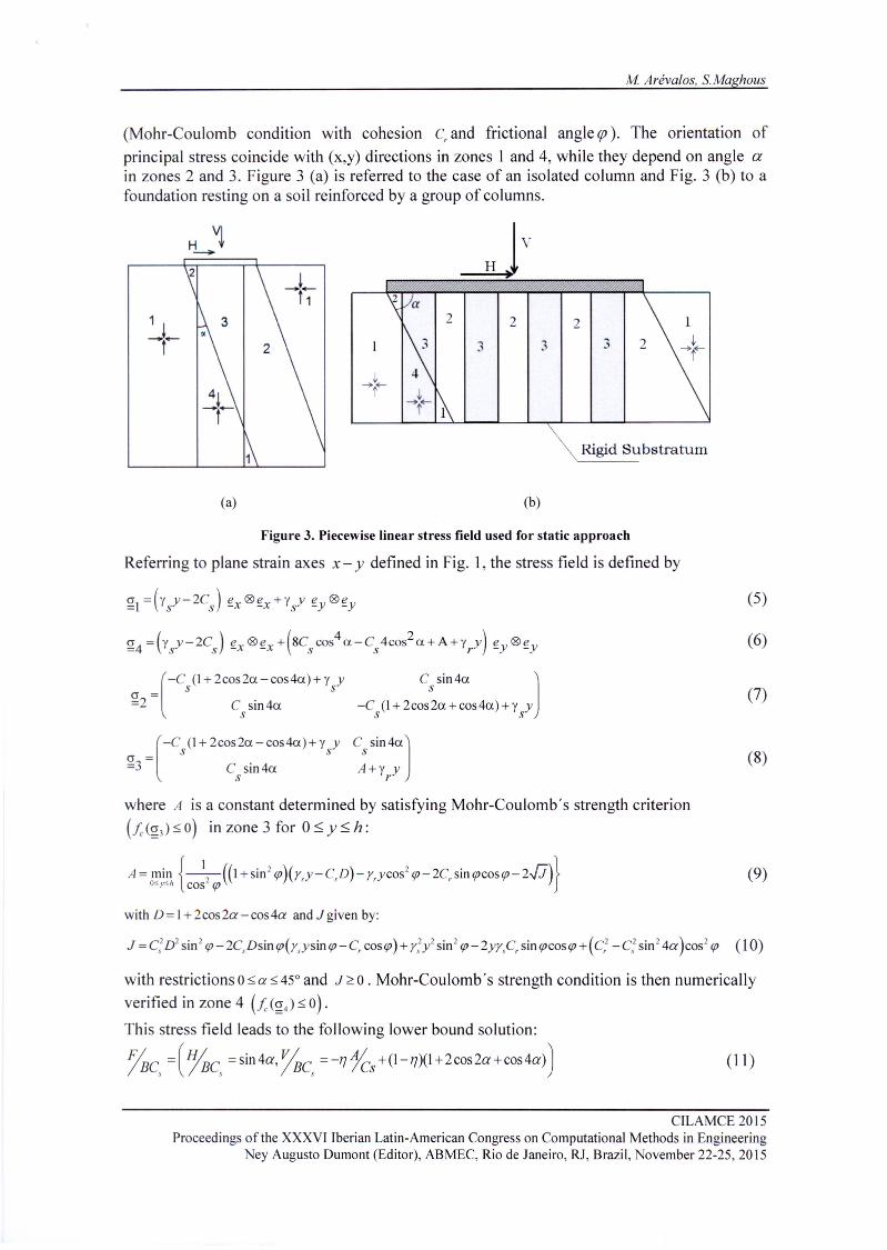
(Mohr-Coulomb condition with cohesion c, and frictional angle cp). The orientation ofprincipal stress coincide with (x,y) directions in zones I and 4, while they depend on angle ain zones 2 and 3. Figure 3 (a) is referred to the case of an isolated column and Fig. 3 (b) to afoundation resting on a soil reinforced by a group of columns.
H '1--
(a)
Rigid Substratum
Figure 3. Piecewise linear stress field used for static approach
2 2
(b)
Referring to plane strain axes x- y defined in Fig. 1, the stress field is defined by
o = (-Cs(l + 2cos2a -cos4a) + ysy C sin4a ]
=2 C sin4a -C (1+2coss2a+coS4a)+y ys s s
(
-C (l+2cos2a-cos4a)+y y CsSin4a]c = s s=3 C sin4a A+y y
s r
(5)
(6)
(7)
(8)
where A is a constant determined by satisfying Mohr-Coulornbs strength criterion(fc(g) s o) in zone 3 for 05, Y 5, h:
A = min {_1_2-((I +sin ' <p)(Ysy-CsD)- y,ycos2 <p-2C, sin <pcos<p-2..[.i)}O~y<h cos <p (9)
with restrictions O ~a ~45° and J ~ O. Mohr-Coulombs strength condition is then numericallyverified in zone 4 (fc(g4) ~ o).This stress field leads to the following lower bound solution:
CILAMCE 2015Proceedings ofthe XXXVI Iberian Latin-American Congress on Computational Methods in Engineering
Ney Augusto Dumont (Editor), ABMEC, Rio de Janeiro, RJ, Brazil, November 22-25,2015
Yield Design Solutions to Bearing Capacity ora Column-rein[orced Soi! Foundation under inclined loading
It is recalled that, for r, ==y" the loads F;=(H=O,v=(1r+2)BC,) and F; =(H=BCs,v=O)
respectively derived by Prandtl (1923) and Salençon and Pecker (1995) for foundation Iyingon homogeneous cohesive soi!, are lower bound solutions for the bearing capacity in thecolumn reinforced situation soil for the case of a purely cohesive reinforcement material.
5 KINEMATIC APPROACH
This approach is based on the implementation ofthree failure mechanisms for the case ofan isolated column and three failure mechanisms for the case of a group of columns.
5.1 The Case of ao Isolated Column
Failure Mechanism I. The first mechanism displayed in Fig. 4 consists in a translationalmotion of the volumes A' AEG and ADC, while the velocity Y.. = U ~IJ is constant andorthoradial in the fan AEC. This failure mechanism involves velocity jumps along lines A'G,GE, AE, CD and circular are EC.
~vH
v
y
x
Figure 4. Generalized Prandtl type failure mechanism I
The rate of work w (F) performed by the externaI force F is obtained by:ex
W (F) =UFsin(a+S)ex (12)
where 8 is used to denote the inclination angle of applied load (Fig. 4) and U represents the
virtual velocity of volume A' AEG. The rate of work we)r"r,) performed by the gravity forces
ClLAMCE 2015Proceedings ofthe XXXVllberian Latin-American Congress on Computational Methods in EngineeringNey Augusto Dumont (Editor), ABMEC, Rio de Janeiro, Ri, Brazil, November 22-25, 2015
maximum resisting work is obtained by using Eq. 4, yielding:
W UZ) = .!.C,uB(J -'1)(_1_+«1+31l"12-2X)Sin(x+a)-COs(x+a)).JA)+ C,uBmrycosq>mr 2 cos a cos(a + q»
the
(14)
Applying the fundamental kinematic equality, Eq. (3), yields
~ s min f(a)BC a sin(a+o)
s(15)
f(a) is given by Eq. 16:
f( a) = .!.(l-rü(-I- + [(I+ 31l"/ 2- 2x)sin(x + a)- cos(X+a) ].JA)+ rn17 cos<p2 cosa cos(a + rp)
. [(1- 1'))2 1 1 1 2 ]-I; SIO a tan a + -l1(l-l1)tan(a + c) + - k1')(I-11) tan(a) + - kll tan(a + rp)4 4 2 2
+.!.I;(I_1'))2 AsinX8
(16)
'h 7r d 7rwit O:5:a :5:--epan X+a:5:-2 2Failure Mechanism 11. The second mechanism, shown in Fig. 5, is defined by the zonesA IAGED and ACG in translational movement. The lines A ID, DE, EG ,GC and AG arediscontinuity surfaces for the velocity.
f\lvH
v
y
H
IIIIIIIIIIIIIIIIIIIII!E----- B
·····-.
A'
Figure 5. Two translational zones failure mechanism 11
The rate ofwork W performed by externai forces is obtained by:ex
W (F) = UFsin(a + o) +.!.UB2y (J -'1)(sin a(I-'1 + k'1).JA - Acosa)ex 2 s
(17)
ClLAMCE 2015Proceedings ofthe XXXVI Iberian Latin-American Congress on Computational Methods in Engineering
Ney Augusto Dumont (Editor), ABMEC, Rio de Janeiro, RJ, Brazil, November 22-25,2015
Yieid Design Soiutions to Bearing Capacity of a Coiumn-reinforced Sai! Foundation under inclined ioading
withA=tana+ 17tan
(a+<p) and U represents the virtual velocity of volume A'AGED (Fig.5).1-17
On the other hand Eq. 18 presents the maximum rate of work W developed for the samemrvelocity field:
W = CSU(1-17)(_I_+[sina+cosatan fi + cosa ]n + __ m_17-,--co_s....:.<p__ )mr cosa cosfisinfi cos(a+<p)(1-17)
Applying Eq. (3) leads to the following inequality:
Failure Mechanism lIl. The failure mechanism is defined by the rotation of blockA'CDEabout axisili. The block is delimited by two circular arcsA'CandDE, and the log-spiral curve CD having the focus n and angle cp (Fig. 6). This mechanism is similar to theone used by Bouassida and Hadhri (1995), with two differences: for one hand gravity forcesare considered in this analysis and for the other, an inclined force is studied.
Similar analysis to those presented for Failure Mechanism I and 11was developed, and onceagain, application of kinematical condition, Eq. (3), yields an upper bound solution of theform
~::;min g(BpB2)BC 9,,9,
S
where function g(B"B2) depends on the dimensionless parameters defined in Eq.(I).
~vH
v
x
E
:<.-- B ------...
Figure 6. Rotational failure mechanism 111
(21)
ClLAMCE 2015Proceedings ofthe XXXVllberian Latin-American Congress on Computational Methods in EngineeringNey Augusto Dumont (Editor), ABMEC, Rio de Janeiro, RJ, Brazil, November 22-25, 2015
M Arévalos, S.Maghous
5.2 The Case of a Group of Columns
Failure Mechanism I. The mechanism presented in Fig. 7 consists in a translational motionofthe volumes A' AEG and ADC, while the velocity rL = Uo ~f) is constant and orthoradial in thefan AECThis failure mechanism involves velocity jumps along lines A'GE,AE,CD andcircular are EC.
~vH
Figure 7. Generalized Prandtl type failure mechanism I
Applying the fundamental kinematic equality Eq. (3), by previously calculating the maximumresisting work (Eq. 4) and the rate ofwork W performed by externai forces, an upper boundexsolution is obtained ofthe form:
~ s min f(a)BC a sin (a +0)
s(22)
where 8 is used to denote the inc1ination angle of applied load (Fig. 7) and f( a) is given byEq.24:
f(a)=r[sen(x+a)(l+ 37í -2X)+COS(x+a)]+ 1-1]-a + m1]cosrp2 cosa cos(a + rp)
-qsin a[~tan a(I-1] - a)2 +tan(a + rp)[,1] ni 1i+ ~k1]2)+ 1k tan++ / i 1 (n- i))]2 n i=1 2 n i=1
-Ç" sin a[~ a( 1]tan(a + rp)- tan a(I-1] - a)}] + ~qr2 sin(x + a)sin X
and r = ~a2 + [(1-7] - a) tan a + 7] tan(a + cp)t with conditions: O S; a S; !!.- - rp and X + aS; 7í2 2
(23)
Failure Mechanism lI. The second mechanism defined by the zones A'AGDand ACG intranslational movement is shown in Fig. 8. The lines A' D, DG, GC and AG are discontinuitysurfaces for the velocity.
CILAMCE 2015Proceedings ofthe XXXVI Iberian Latin-American Congress on Computational Methods in Engineering
Ney Augusto Dumont (Editor), ABMEC, Rio de Janeiro, RJ, Brazil, ovember 22-25,2015
Yield Design Solutions to Bearing Capacity ora Column-reinforced Soi! Foundation under inclined loading
tsJvH
G
Figure 8. Two translational zones failure mechanism 11
The application of Eq. (3) leads to the following inequality:
_F_ s min ---=g-,(_u"-) _BC a.p sin(u+o)
s(24)
where
[I 2 (I n-I ) I 2 ]g(u)=-çsena -tana(l-17) +17tan(a+tp) - I i+a +-k17 tan(a + tp)2 ni=1 2
[ n-I] I 2-çsena akn tssi a+nkl uuva I (n-i) +-çcosa[(J-17)tana+l]tan(a+tp)]i= 1 2
+ 1-17 + [(l-17)tan a + 17tan(a + tp) l( sin a + 2../2 cosa) + m17costpcosa cos(a + tp)
(25)
with condition: Os a s 7r -cp2
Failure Mechanism IH. The third failure mechanism presented in Fig. 9 is defined by therotation of block A'CDabout axis nz. The block is delimited by circular ares and log-spiralcurves having the focus o and angle cp.
Application ofkinematical condition, Eq. (3) yields an upper bound solution ofthe form
(26)
where function f(()1'()2) depends on the dimensionless parameters defined In Eq. (1). A
numerical minimization over ()I and ()2 is performed.
ClLAMCE 2015Proceedings ofthe XXXVllberian Latin-American Congress on Computational Methods in EngineeringNey Augusto Dumont (Editor), ABMEC, Rio de Janeiro, RJ, Brazil, November 22-25,2015
The static approach is defined by the boundary of the surface which, in the space (H, V)
or (F,8) , for a fixed set of parameters {k,m,cp";,I],h/ B} presented in Eq. 1, delineates the set ofsafe loads. This method approximates the extreme loads "from inside", while the kinematicapproach does it "from outside".
For illustrative purposes, Fig. 10 shows the resuIts obtained in the context of this analysis fora cohesive soil reinforced by a column consisting of original soil blended with lime(Cr>Cs' qJ=O).
As it could be expected the reinforcing effect induced by cohesive columns is increasing withratio C, / Cs. Unlike the static approach, the kinematic approach predicts improvement of thebearing capacity in both horizontal and vertical directions of the load, thus emphasizing thenecessity to resort to more sophisticated stress distributions.
The variation of the lower and upper bound estimate as a function of the cohesion ratio m fora purely vertical load is presented in Fig. 11. The static approach shows that reinforcementoccurs from a cohesion ratio m = 2.6 and m = 3.4 for replacement ratios of 7J = 0.4 and7J = 0.25 respectively.
The second application refers to reinforcement by means of purely frictional columns(C, = O, qJ# O). Figure 12 shows the results obtained for two values of the column friction
angle. The reinforcement reveals effective only for sufficiently high values of cp. Similarly tothe resuIts developed in Salençon and Pecker (I995b), it is also observed that the lower boundestimates tend to zero as the load direction is closer to the horizontal one.
CILAMCE 2015Proceedings ofthe XXXVI Iberian Latin-American Congress on Computational Methods in Engineering
ey Augusto Dumont (Editor), ABMEC, Rio de Janeiro, RJ, Brazil, ovember 22-25, 2015
Yield Design Solutions to Bearing Capacity of a Column-reinforced Soil Foundation under inc/ined loading
ICr/Cs=S I n= L,~.0.4, ~=0.5.",.0', k-L, h/S. I 1 cr/Cs=21-- Statlc Approach- . - Kinematie Approach
'" - • • •• Non..•.elnforced soil '"U. U~8- , ~8
" -- ," r
<, ," &- ,
. .. .,#4 - .... ..
2-
I
·2 o ·2 oH/BCs HlBCs
Figure 10. Lower and upper bound approach for the bearing capacity domain for cohesive columns
Figure 11. Lower and upper bound approach for the bearing capacity domain of a purely verticalloadingfor cohesive columns
10
'"olE .>" ,
" 8
n=1. ~=0.4, =0.5, m=O,k= I. h/b=l-- Stalic Approach- . - Klnematic Approach- • • •• Non-reinf()(ced sail '" 10 lo
~
",-30'
,,, ,
,
..········
..·········2 ·1 O
HlBCs·2 ·1 o
HlBCs
Figure 12. Lower and upper bound approaches for the bearing capacity domain for purely frictionalcolumns
ClLAMCE 2015Proceedings ofthe XXXViiberian Latin-American Congress on Computational Methods in EngineeringNey Augusto Dumont (Editor), ABMEC, Rio de Janeiro, RJ, Brazil, November 22-25, 2015
M Arévalos, SMaghous
The evolution of the lower and upper bound estimates with friction angle rp is shown inFig.13 for a purely vertical load V . The static approach indicates that reinforcement occursfrom the friction angle tp = 20° for a replacement ratio of1] = 40% , while for 25% it happensfrom rp = 27° . The increase of the bearing capacity depends of these two parameters:1]and ip .
O -+-----,,------.------,,----+-----,,------.------,----,------,----,
5,14.-=:'UOILL."--=--=-~-------4
O -+--,------.------,,----,-----,,--,---,--,---,----,
O 10 20 30 40 50 O 10 20 30 40 50
Figure 13. Lower and upper bound approaches for the bearing capacity domain for purely frictionalcolumns
Table 1 summarizes the results obtained in this work and values from Bouassida and Hadhri(1995) for illustrative examples. The static approach given by these authors corresponds to aparticular case of the stress field considered in this work (when a = 0° and gravity isneglected), therefore, same values of the lower bound were obtained. As regard to the upperbound, better estimations of the limit load were founded in comparison with Bouassida andHadhri (1995).
Table 1. Results for a purely frictional column material
1] Lower Bound by Lower Bound by Upper Bound by Upper Bound by thethe static approach Bouassida and Bouassida and kinematic approach
Hadhri (1995) Hadhri (1995)
cp = 25° cp = 30° tp = 25° tp = 30° rp = 25° rp = 30° rp = 25° cp = 30°
0.2 4.18 4.40 4.19 4.40 5.99 6.32 5.71 6.07
0.4 4.37 4.80 4.37 4.80 6.51 7.21 6.37 7.07
0.6 4.56 5.20 4.56 5.20 7.11 8.25 7.11 8.25
CILAMCE 2015Proceedings ofthe XXXVI lberian Latin-American Congress on Computational Methods in Engineering
ey Augusto Dumont (Editor), ABMEC, Rio de Janeiro, RJ, Brazil, November 22-25,2015
Yield Design Solutions to Bearing Capacity ora Column-reinforced Soil Foundation under inclined loading
6.2 The Case of a Group of Columns
In the same form adopted in the previous section, two categories of column materiais aresubsequently studied. The combination of static and kinematic approaches provides lower andupper bounds domains for the bearing capacity for each category. An illustrative example ofsuch approaches for a purely cohesive column material (Cr> Cs' cp = O) is first presented.
Figure 14 relates the extreme non dimensional externai force ~with the inclination angleBCs
S of the load. Both the static and kinematic approaches predict an improvement of theextreme load for inclination angles between O~ S ~ 20°. The interaction between the non-dimensional load components of the upper and lower bound estimates (Fig. 14) shows that anincrease on the horizontal component of the force implies a reduction of the vertical bearingcapacity.
Figure 14. Lower and upper bound estimates for the bearing capacity domain for purely cohesive columns
Figure 15 refers to reinforcement by means of purely frictional columns (C, = O, cp 7: O). Thelower and upper bound estimates are compared to the ultimate bearing capacity of a non-
reinforced soil in Fig.15 relating the Force ~ to its inclination angle S. Results areBCs
conveniently presented in the plane (~,~) in Fig. 15 as the lower and upper domainsBCs BCs
of the extreme loads. For both categories of material reinforcement, the ultimate bearingcapacity could only be bracketed. Generally, upper bound estimates lead to betterapproximations of the bearing capacity, therefore, more sophisticated stress distributionsshould be considered in order to conceal extremes loads boundaries with a higher degree ofaccuracy.
CILAMCE 2015Proceedings of the XXXVllberian Latin-American Congress on Computational Methods in EngineeringNey Augusto Dumont (Editor), ABMEC, Rio de Janeiro, RJ, Brazil, November 22-25, 2015
Figure 15. Lower and upper bound approach for the bearing capacity domain for purely frictionalcolumns
Analytical and elastoplastic simulations were performed by Hassen G. et ai (2013) based on aperiodic homogenization limit analysis method to determine the homogenized strengthcapacity of column reinforced soi!. Upper bound estimates of the ultimate bearing capacityusing the previously obtained numerical estimate of the strength domain for a purely verticalload in plane strain analysis have been derived. Table 2 compares this result with the upperand lower bound studied in this work for the fixed set of parameters:{n = 6, 17 = 0.28, rp = 35°, k = O,ç = 0, m = 0, I = 0.15}. The difference between these upper
bounds is 4%.
Table 2. Results for a group of purely frictional column material
Lower Bound by Upper Bound by Hassen G. et ai Upper Bound bythe Static (2013) using homogenization the KinematicApproach approach and yield design theory Approach
5.01 7.15 7.76
7 CONCLUSIONS
The problem solved in the current study, relates to the ultimate bearing capacity of a stripfooting resting on the surface of a column reinforced soil subjected to an inclined, centralload. The extreme load is defined within the framework of the plane strain yield design theoryusing the yield strengths ofthe materiais involved. Both lower and upper bound solution havebeen derived in the situation of a single column and of a group of columns.
The novelty of this contribution is in its ability to deal with inclined loads situation. Theanalysis may be viewed as a generalization of existing approaches developed in the case ofvertical loading. The results bracket the variations of the bearing capacity as a function of
CILAMCE 2015Proceedings ofthe XXXVI Iberian Latin-American Congress on Computational Methods in Engineering
ey Augusto Dumont (Editor), ABMEC, Rio de Janeiro, RJ, Brazil, November 22-25,2015
Yield Design Solutions to Bearing Capacity o[ a Column-reinforced Soi! Foundation under inclined loading
either the load inclination or the column and soil strength parameters. The interaction betweenthe load components showed that as soon as the horizontal component of the force increases,the vertical component of the bearing capacity decreases. This aspect should thus be carefullyconsidered in foundation designo
The foundation ultimate bearing capacity has been compared with available solutions derivedfor purely vertical load.
REFERENCESBouassida M., Hadhri T., 1995. Extreme load of soils reinforced by columns: the case of anisolated column. Soils and Foundations vol. 35, pp. 21-35.
Bouassida M., Jellali B. & A. Porbaha, 2009. Limit analysis of rigid foundations on floatingcolumns. International Journal ofGeomechanics vol. 9, pp. 89-101.
Datye, K. R., Madhav, M. R., 1988. Case histories offoundations with stone columns. SecondInternational Conference on Case Histories in Geotechnical Engineering, pp. 1075-1086.
Hassen O., Gueguin M., de Buhan P., 2013. A homogenization approach for assessing theyield strength properties of stone column reinforced soils. European Journal of MechanicsA/Solids., vol 37, pp. 266-280.
Jellali B., Bouassida M. & de Buhan P, 2005. A homogeneization method for estimating thebearing capacity of soils reinforced by columns. International Journal for numerical andanalytical methods in geomechanics. vol. 29, pp. 989-1004.
Jellali B., Bouassida M., de Buhan P., 2007. A homogenization approach to estimate theultimate bearing capacity of a stone column reinforced foundation. International Journal ofgeotechnical engineering, vol. 1, pp. 61-69.
Nazari L, Ghazavi M., 2012. A simple analytical method for calculation ofbearing capacityof stone-column. International Journal ofCivil Engineering, vol. 1, pp. 15-25.
Prandtl L., 1923. Anwendungbeispiele zu einem Henckyshen Satz über das plasticheGleischgewicht, Z. Angew. Math. Mech., vol. 3, pp. 401.
Salençon L, 1990. An introduction to the yield design theory and its applications to soilmechanics. European Journal of Mechanics - A/Solids, vol. 9, pp. 447-500.
Salençon L, Pecker A., 1995. Ultimate bearing capacity of shallow foundations under inclinedand eccentric loads. Part I: purely cohesive soil. European Journal of Mechanics-A/Solids, vol3, pp. 349-375.
Salençon L, Pecker A., 1995b. Ultimate bearing capacity of shallow foundations underinclined and eccentric loads. Part lI: purely cohesive soil without tensile strength. EuropeanJournal of Mechanics-A'Solids, vol 3, pp. 349-375.
Schaefer, V. R. Ground improvement, ground reinforcement, ground treatment.Developments 1987-1997, 1997. Proceedings of Soil Improvement and Geosynthetics of theGeo-insitute of the American Societey of Civil Engineers in Conjunction with Geo-Logan '97.pp. 75 and 102.
ClLAMCE 2015Proceedings of the XXXV11berian Latin-American Congress on Computational Methods in EngineeringNey Augusto Dumont (Editor), ABMEC, Rio de Janeiro, RJ, Brazil, November 22-25, 2015