QIB XT -F12 Protecting America's Future INATIONAL COMPLEX Y/LF-717 Docket No. 71-9315 Safety Analysis Report, Y-12 National Security Complex, Model ES-3100 Package with Bulk HEU Contents Volume I Sections 1-2 BWXT Y-12, L.L.C. February 25, 2005 MANAGED BY BWXT Y12, LLC . FOR THE UNITED STATES DEPARTMENT OF ENERGY UCN-13672 (11.03)
Transcript
QIB XT-F12
Protecting America's Future
INATIONALCOMPLEX
Y/LF-717Docket No. 71-9315
Safety Analysis Report,Y-12 National Security Complex,
Model ES-3100 Packagewith Bulk HEU Contents
Volume ISections 1-2
BWXT Y-12, L.L.C.
February 25, 2005
MANAGED BYBWXT Y12, LLC .FOR THE UNITED STATESDEPARTMENT OF ENERGY
UCN-13672 (11.03)
I - i
DISCLAIMER
This report was prepared as an account of work sponsored by an agency of theUnited States Government. Neither the United States Government nor any agencythereof, nor any of their employees, makes any warranty, express or implied, orassumes any legal liability or responsibility for the accuracy, completeness, or use-fulness of any information, apparatus, product, or process disclosed, or representsthat its use would not infringe privately owned rights. Reference herein to anyspecific commercial product, process, or service by trade name, trademark, manu-facturer, or otherwise, does not necessarily constitute or imply its endorsement,recommendation, or favoring by the United States Government or any agencythereof. The views and opinions of authors expressed herein do not necessarilystate or reflect those of the United States Government or any agency thereof.
Y/LF-717, Vol. 1
SAFETY ANALYSIS REPORT,Y-12 NATIONAL SECURITY COMPLEX,
MODEL ES-3100 PACKAGE WITH BULK HEU CONTENTS
Prepared by theOak Ridge Y-12 National Security Complex
Oak Ridge, Tennessee 37831Managed by
BWXT Y-12 L.L.C.for the
U. S. Department of Energyunder contract DE-AC05-840R21400
February 25, 2005
Y/LF-717/Int"oES-3 100 HEU SARPkmdD2-2505
It
DISCLAIMER
This report was prepared as an account of work sponsored by an agency of the United StatesGovernment Neither the United States Government nor any agency thereof, nor any of theiremployees, makes any warranty, express or implied, or assumes any legal liability or responsibilityfor the accuracy, completeness, or usefulness of any information, apparatus, product, or processdisclosed, or represents that its use would not infringe privately owned rights. Reference hereinto any specific commercial product, process, or service by trade name, trademark, manufacturer,or otherwise, does not necessarily constitute or imply its endorsement, recommendation, orfavoring by the United States Government or any agency thereof. The views and opinions ofauthors expressed herein do not necessarily state or reflect those of the United States Governmentor any agency thereof.
\ '1
The following contractors, consultants, and companies assisted BWXT Y-12, LL.C., in thepreparation of this Safety Analysis Report:
G2 Engineering and Management, Inc.Navarro Research & Engineering, Inc.
UT-Battelle
ii
Y/LF-717/Inno/ES-3100 HEU SAR/kxnd'02-25-05
CONTENTS'
LIST OF FIGURES ..................... -...... xi
LIST OF TABLES . xiii
ACKNOWLEDGMENTS ...................... ; . . .... xvii
EXECUTIVE SUMMARY . xix
ACRONYMS ...................... : ..... xxi
REVISION LOG ........................ ; .xxiii
1. GENERAL INFORMATION . 1-1
1.1 INTRODUCTION .1-1
1.2 PACKAGE DESCRIPTION .. 1-11.2.1 Packaging .1-41.2.2 Containment System . 1-71.2.3 Contents .1-91.2.4 Operational Features .1-7 1
1.3 GENERAL REQUIREMENTS FOR ALL PACKAGES .. . ............... 1-171.3.1 Minimum package size ............................................ 1-171.3.2 Tamper-indicating feature ........................................ ;. .... 1-17
ES-3100 CONTAINMENT VESSEL A. 1-731.4.4 JS-YMN3-801580-A003, REV. B, MANUFA CTURING PROCESS SPECIFICA TION
FOR CASTING KAOLITE 1600TM INTO THE ES-3100 SHIPPING PACKAGE .. 1-871.4.5 JS-YMN3-801580-A005, REV. A; CASTING CATALOG NO. 277-4 NEUTRON
ABSORBER FOR THE ES-31 00 SHIPPING PA CKA GE ................... 1-1071.4.6 PACKAGE CATEGORY DETERMINATION..... .... 1-1431.4.7 HEU OXIDE MATERIAL SPECIFICATION AS PROVIDED BY Y-12 HIGHLY
2.1 DESCRIPTION OF STRUCTURAL DESIGN .2-22.1.1 Discussion ...................... I ......... 2-22.1.2 Design Criteria.2-4 ............... -. . 24
.. .
Y/LF.-717nES-31DO HEU SAR/kmd/02-25.05
CONTENTS continued
2.1.3 Weights and Centers of Gravity ........... ............................. 2-142.1.4 Identification of Codes and Standards for Package Design ..... .............. 2-14
2.2 MATERIALS .......................................................... 2-172.2.1 Material Properties and Specifications ................................... 2-172.2.2 Chemical, Galvanic, or Other Reactions ................................. 2-172.2.3 Effects of Radiation on Materials .......... ............................. 2-26
2.4 LIFTING AND TIE-DOWN STANDARDS FOR ALL PACKAGES ...... ........... 2-312.4.1 Lifting Devices ...................................................... 2-312.4.2 Tie-Down Devices . ................................................. 2-31
2.5 GENERAL CONSIDERATIONS .................... ......................... 2-312.5.1 Evaluation by Test . ................................................. 2-322.5.2 Evaluation by Analysis . ............................................... 2-34
2.6 NORMAL CONDITIONS OF TRANSPORT ............... .................... 2-352.6.1 Heat .................. 2-372.6.2 Cold ................... 2-382.6.3 Reduced External Pressure .................. 2-402.6.4 Increased External Pressure .................. 2-402.6.5 Vibration .................. 2-432.6.6 Water Spray ................................. 2-452.6.7 Free Drop ................................. 2-462.6.8 Comer Drop ................................. 2-462.6.9 Compression ................................. 2-472.6.10 Penetration ................................. 2-49
2.7 HYPOTHETICAL ACCIDENT CONDITIONS ................................. 2-502.7.1 Free Drop ................................. 2-522.7.2 Crush........ .. 2-632.7.3 Puncture .2-692.7.4 Thermal .2-702.7.5 Immersion-Fissile Material ............ .............................. 2-782.7.6 Immersion-All Packages ............. ............................... 2-802.7.7 Deep Water Immersion Test (for Type B Packages Containing More than I05 A2) 2-802.7.8 Summary of Damage . ............................................... 2-80
2.8 ACCIDENT CONDITIONS FOR AIR TRANSPORT OF PLUTONIUM ..... ......... 2-94
2.9 ACCIDENT CONDITIONS FOR FISSILE MATERIAL PACKAGES FOR AIRTRANSPORT ............................................................ 2-94
(DAC-EA-900000-A006 and DAC-EA-900000-A007). : .............. 2-972.10.2 IMPACT ANALYSES OF ES-3 100 'DESIGN CONCEPTS USING BOROBOND
AND CAT 277-4 NEUTRON ABSORBERS .2-155
2.10.3 KAOLITE PROPERTIES .2-.......................'.'.;'....; 24612.10.4 CATALOG 277-4 PROPERTIES ............................. 2-5332.10.5 BOROBOND4 PROPERTIES ....................... '. 2-6412.10.6 RECOMMENDED RANDOM VIBRATION AND SHOCK TEST
SPECIFICATIONS FOR CARGO TRANSPORTED ON SST AND SGTTRAILERS .................................. ...................... 2-655
SECTION 2 REFERENCES ............... 2-673
3. THERMAL EVALUATION ................ 3-1
3.1 DISCUSSION ................................... 3-13.1.1 Design Features ................... '..... 3-33.1.2 Content's Decay Heat ............. 3-43.1.3 SummaryTablesofTemperatures ............................ 3-43.1.4 Summary Tables of Maximum Pressures ................. .......... 3-11
3.2 SUMMARY OF THERMAL PROPERTIES OF MATERIALS ....... .............. 3-163.2.1 Material properties ....................... ... '' 3-163.2.2 Component Specifications ... '..... 3-16
3.3 GENERAL CONSIDERATIONS ...... ......................... 3-163.3.1 Evaluation by Analysis ...................... ; ....... 3-163.3.2 Evaluation by Test ............................... 3-183.3.3 Margins of Safety .3-23
3.4 THERMAL EVALUATION UNDER NORMAL CONDITIONS OF TRANSPORT .... 3-273.4.1 Heat and Cold ................................ ' .;.; .... 3-273.4.2 Maximum Normal Operating Pressure ................................ :.-.. 3-293.4.3 Maximum Thermal Stresses 7-.T.-, . . . . ............. 3-29
3.5 HYPOTHETICAL ACCIDENT THERMAL EVALUATION ........... ............. 3-313.5.1 Initial Conditions . 3-313.5.2 Fire Test conditions ......................... '' 3-313.5.3 Maximum Temperatures and Pressure .......................... , .. 3-333.5.4 Accident Conditions for Fissile Material Packages for Air Transport .3-38
v
YL.F-717/IntwoIES-3100 HEU SARkmnd/2-25-05
CONTENTS continued
3.6 APPENDICES .............. 3-393.6.1 THERMAL EVALUATION OF THE ES-3 100 SHIPPING CONTAINER FOR
NCT AND HAC (CONCEPTUAL DESIGN WITH BOROBOND4 NEUTRONABSORBER) . 341
3.6.2 THERMAL EVALUATION OF THE ES-3 100 SHIPPING CONTAINER FORNCT AND HAC (FINAL DESIGN WITH CATALOG 277-4 NEUTRONABSORBER) . 3-81
3.6.3 THERMAL STRESS EVALUATION OF THE ES-3 100 SHIPPINGCONTAINER DRUM BODY ASSEMBLY FOR NCT (FINAL DESIGNWITH CATALOG 277-4 NEUTRON ABSORBER) .. 3-121
3.6.4 CONTAINMENT VESSEL PRESSURE DUE TO NORMAL CONDITIONSOF TRANSPORT FOR THE PROPOSED CONTENTS .. 3-145
3.6.5 CONTAINMENT VESSEL PRESSURE DUE TO HYPOTHETICALACCIDENT CONDITIONS FOR THE PROPOSED CONTENTS . . 3-153
SECTION 3 REFERENCES .. 3-159
4. CONTAINMENT .. 4-1
4.1 DESCRIPTION OF THE CONTAINMENT BOUNDARY .......................... 4-24.1.1 Containment Boundary ........................................... 4-24.1.2 Special Requirements for Plutonium ........ . ............... 4-4
4.2 GENERAL CONSIDERATIONS ............................... 4-44.2.1 Type A Fissile Packages ............................... 4-44.2.2 Type B Packages ............................... 4-4
4.3 CONTAINMENT UNDER NORMAL CONDITIONS OF TRANSPORT (TYPE BPACKAGES) ............................... 4-6
4.4 CONTAINMENT UNDER HYPOTHETICAL ACCIDENT CONDITIONS (TYPE BPACKAGES) ............................... 4-8
4.5 LEAKAGE RATE TESTS FOR TYPE B PACKAGES ............ ................ 4-10
4.6 APPENDICES . 4-114.6.1 DETERMINATION OF A2 FOR THE ES-3100 PACKAGE WITH HEU
CONTENTS . 4-134.6.2 CALCULATION OF THE ES-3 100 CONTAINMENT VESSEL'S
REGULATORY REFERENCE AIR LEAKAGE RATES . 4-23
SECTION 4 REFERENCES . 4-35
SHIELDING EVALUATION ... 5-1
5.1 DESCRIPTION OF SHIELDING DESIGN .. 5-15.1.1 Design Features .5. S-15.1.2 Summary Table of Maximum Radiation Levels ... 5-1
5.3 DOSE RATE ANALYSIS MODELS .......................... 5-35.3.1 Packaging Model Conservative Features .5-75.3.2 Photon model for 36-kg HEU. metal content .5-95.3.3 Neutron model for 36-kg HEU metal content ........................ 5....... 5-115.3.4 Photon model for 24-kg HEU oxide content . 5-115.3.5 Neutron model for 24-kg HEU oxide content . 5-11
5.4 SHIELDING EVALUATION . 5-11
5.5 APPENDICES ...................................... 5-155.5.1 ORIGEN NPUT DATA FROM TABLE 5.3 .5-175.5.2 CSASN AND ICE INPUT FROM TABLE 5.8 .5-215.5.3 MORSE ROUTINES AND INPUT DATA .5-25
SECTION 5 REFERENCES .545
6.. CRITICALITY EVALUATION . 6-1
6.1 DESCRIPTION OF THE CRrMICALrTY.DESIGN ................................. 6-16.1.1 Design Features .6-16.1.2 Summary of the Criticality Evaluation ............ ....................... 6-16.1.3 Criticality Safety Index .................... 6-3
6.2 PACKAGE CONTENTS ................. 6-216.2.1 Fissile Material Contents ................. ;..... 6-216.2.2 Convenience Cans and Cat 2774 Canned Spacers .6-226.2.3 Packing Materials ........... I ..... 6-226.2.4 Package Content Loading Restrictions .6-23
6.3 GENERAL CONSIDERATIONS ................. ........................ 6-246.3.1 Model Configuration .; 6-256.3.2 Material Properties .................. ;;;; . 6-386.3.3 Computer Codes and Cross Section Libraries . 6466.3.4 Demonstration of Maximum Reactivity . 648
6.4 SINGLE PACKAGE EVALUATION .......................... ; . . . 6496.4.1 Solid HEU Metal of Specified Ge6metric Shapes .... 6-506.4.2 HEU Solid Metal of Unspecified Geometric Shapes or HEU Broken Metal . 6-526.4.3 HEU Oxide ........ -. 6-536.4.4 UNH Crystals ................................................................ 6-54
6.5 EVALUATION OF PACKAGE ARRAYS UNDER NORMAL CONDITIONS OFTRANSPORT ................................... 6-556.5.1 Solid HEU Metal of Specified Geometric Shapes . 6-556.5.2 HEU Solid Metal of Unspecified Geometric Shapes or HEU Broken Metal ...... 6-576 . . .E O.d . ................. : . ........................................ 6 -56.5.3 HEU Oxide .... :; 6-576.5.4 UNH Crystals ........ 6-58
vii'
Y/Fi-717/inmrnJES-3 I100 HIEU SAR/kmd/02-25.05
-
|
CONTENTS continued
6.6 EVALUATION OF PACKAGE ARRAYS UNDER HYPOTHETICAL ACCIDENTCONDITIONS ............................................................ 6-586.6.1 Solid HEU Metal of Specified Geometric Shapes . ......................... 6-596.6.2 HEU Solid Metal of Unspecified Geometric Shapes or HEU Broken Metal ...... 6-606.6.3 HEU Oxide ........................................................ 6-606.6.4 UNH Crystals ...................................................... 6-61
6.7 FISSILE MATERIAL PACKAGES FOR AIR TRANSPORT ....................... 6-616.7.1 Configuration (Not evaluated) . ........................................ 6-616.7.2 Results (Not evaluated) . .............................................. 6-61
1.1 Schematic of the ES-3 100 shipping package . ........................................ 1-21.2 Exploded view of the ES-3 100 package with bulk HEU contents ......... ................ 1-31.3 Containment boundary of the ES-3 100 shipping package ................................ 1-81.4 Typical shipping configurations inside the ES-3100 containment vessel ................. 1-152.1 Containment vessel calculated stress locations '.;.................................. e ....... 2-112.2 ES-3 100 shipping package center of gravity locations .......... ...................... 2-152.3 ES-3 100 vibration testing arrangement ............................................ 2-442.4 Water spray test arrangement for Test Unit-4 -; .................................. ........ 2-452.5 NCT free drop test on Test Unit4 ................................................ 2472.6 Compression test on Test Unit-4 . .2-48...... ;. ;- .2.7 Penetration test damage on Test Unit4 ............................ 2492.8 9-m drop test arrangement for all test units .............................. '. 2-532.9 9-m drop test damage on Test Unit-4 ............................ 2-552.10 Cumulative damage from 9-mrdrop and crush testing on Test Unit-2 ....... ............. 2-572.11 Test Unit-3 damage from 1.2 and 9-m drop tests .............. ...................... 2-582.12 1.2 and 9-m drop test damage on Test Unit-1 ...................................... 2-602.13 1.2 and 9-m drop test damage to Test Ufiit-5 ........................................ 2-622.14 Cumulative damage following 9-m crush on TestUnit-I ......... ............. 2-642.15 Cumulative damage following 9-m crush test on Test Unit-3 . ............................ 2-662.16 Cumulative damage from 9-m drop and crush testing on Test Unit-4 .......... ........... 2-672.17 Cumulative damage from 9-m drop and crush testing on Test Unit-5 ........ . ... 2-692.18 280 oblique and horizontal puncture tests on Test'Unit-I .2-712.19 400 oblique puncture test on Test Unit-i. .............................- 2-712.20 Horizontal puncture test over Test Unit-i's containment vessel flange . 2-722.21 Horizontal CG puncture test on Test Unit-2 .. ... ..................................... 2-722.22 24.60 oblique puncture test on Test Unit-3 ....................................... 2-732.23 Vertical puncture test on Test Unit4 ........... ................................. 2-732.24 Horizontal puncture test over Test Unit-5's containment vessel flange ..... ............. 2-742.25 Visual comparison of the cumulative damage on the crush side surface after the three drop
tests (from top to bottom: Test Unit-i, analytical results with BoroBond, analytical resultswith Cat 2774) ............................................................. 2-83
2.26 Visual comparison of the cumulative damage on the rigid surface side after the four droptests (from left to right: Test Unit-2, analytical results with BoroBond, analytical resultswith Cat 2774) ............................................................. 2-86
2.27 Visual comparison of the cumulative damage on the crush plate side after the three droptests (from left to right: Test Unit-2, analytical results with BoroBond, analytical resultswith Cat 2774) ............................................................. 2-86
2.28 Visual comparison of the cumulative bottom damage after the three drop tests (from left toright: Test Unit-3, analytical results with BoroBond, analytical results with Cat 2774) .... 2-88
2.29 Visual comparison of the cumulative lid damage after the three drop tests (from top tobottom: Test Unit-3, analytical results with BoroBond, analytical results with Cat 2774) .. 2-89
2.30 Visual comparison of the cumulative damage after the three drop tests (from left to right:Test Unit4, analytical results with BoroBond, analytical results with Cat 2774) ..... .... 2-91
2.31 Containment vessel markings at assembly (swivel hoist ring removed prior to testing) ..... 2-932.32 Containment vessel marking after compliance testing ............................... 2-943.1 MSC.Patran axisymmetric finite element model of the ES-3 100 shipping container with
BoroBond4-nodal locations of interest (elements representing air not shown for clarity) ... 3-6
xi
YAYJ-717/jnvonJES-3 I 00 HIEU SAR/kni,/02-25-0S
__-
LIST OF FIGURES continued
3.2 Test unit preheat arrangement....................................... 3-243.3 Test unit insertion into furnace .3-243.4 Test unit removal from furnace....................................... 3-253.5 Test unit cool down and monitoring arrangement . 3-255.1 Cylindrical calculational model of the ES-3 100 shipping package for NCT . 5-65.2 ES-3 100 HEU metal content radial (top view) geometric models . 5-106.1 /Z section view of ES-3 100 package . 6-266.2 R'Z section view at bottom of ES-3 100 package showing KENO V.a geometry units 1001,
1002, and 1003 (partial) .6-276.3 R/Z section view at center of the ES-3 100 package showing KENO V.a geometry unit 1003
(partial) .................................. 6-286.4 R/Z section view of near top of the ES-3 100 package showing KENO V.a geometry units
1003 (partial) and 1010-1016 . 6-296.5 R/Z section view at top of the ES-3100 package showing KENO V.a
geometry units 1016-1019 . 6-306.6 R/Z section view of ES-3 100 package . 6-326.7 RIZ section view at bottom of ES-3100 package showing KENO V.a geometry units 1001,
1002, and 1003 (partial) of the array model .6-336.8 R/Z section view at center of the ES-3 100 package showing KENO V.a geometry unit 1003
(partial) of the array model .6-346.9 R/Z section view of near top of the ES-3 100 package showing KENO V.a geometry units
1003 (partial), and 1010 through 1016 of the array model .6-356.10 RIZ section view at top of the ES-3100 package showing KENO V.a geometry units 1016
through 1019 of the array model . 6-368.1 Label for use on the exterior surface of the containment vessel and the drum . 8-6
xii
Y/LF-717/1nrro'ES-3 100 HEU SAR/kmd'02-25-05
LIST OF TABLES
1.1 Uranium concentration limits .............. 1-101.2 Bounding uranium isotopic concentrations in oxide .1.-1.3 Authorized content and fissile mass loading limits for the ES-3 100 . 1-132.1 Proposed HEU contents for shipment in the ES-3 100 ................................... 2-12.2 Category designations for Type B packages .2-7
2.3 Summary of load combinations for normal and hypothetical accident conditions of transport . . 2-92.4 Containment vessel allowable stress .......................... 2-102.5 Allowable stress intensity (S ,,) for the containment boundary construction materials of
construction ...... : ' 2-102.6 ES-3 100 containment boundary design evaluation allowable stress comparisons .2-122.7 ES-3 100 packaging material specifications .............................. '. 2-132.8 Packaging weights for various ES-3 100 shipping package arrangements ................. 2-162.9 Compliance test unit weights ................... 2-172.10 Calculated center of gravity for the various ES-3 100 shipping arrangements .2-182.11 Applicable codes and standards for Category.I packaging .2-202.12 Mechanical properties of the metallic components of the drum assembly .2-212.13 Mechanical properties of the lid fastening components for the drum assembly .2-222.14 Mechanical properties of the cast refractory insulation .2-232.15 Mechanical properties of containment vessel 0-rings .2-232.16 Mechanical properties of the metallic components of the containment boundary .2-242.17 Mechanical properties of the cast neutron absorber, 2-252.18 Summary of NCT- lOCFR71.71 tests for ES-3100 package .2-332.19 Summary of HAC- IOCFR71.73 tests for ES-3100 package .......... ............ 2-332.20 Summary of temperatures and pressures for.NCT .2-362.21 ES-3 100 containment boundary evaluation for both hot and cold conditions .2-412.22 NCT ES-3 100 containment boundary stress compared to the allowable stress at reduced and
increased external pressures .2................. ......- 2422.23 Test and analysis summary for the ES-3 100 package ................................ 2-512.24 Recorded height damage to Test Unit-4 from 1.2-m and 9-m drop testing ..... ........... 2-542.25 Recorded diametrical damage to Test Unit4 from 1.2-m and 9-m drop tests ..... ......... 2-542.26 Recorded diametrical damage to Test Unit-2 from NCT and HAC drop testing ... .......... 2-562.27 Recorded flat contour damage to Test Unit-2 from NCT and HAC drop testing ............. 2-562.28 Recorded height damage to Test Unit-2 from NCT. and HAC drop testing ..... ........... 2-562.29 Recorded height damage to Test Unit-3 from 1.2-m and 9-m drop testing ..... 2-582.30 Recorded diametrical damage to Test Unit-3 from 1.2-m and 9-m drop testing ...... ....... 2-582.31 Recorded height damage to Test Unit-i from 1.2-m, and 9-m drop testing ..... ........... 2-592.32 Recorded diametrical damage to Test Unit-I from 1.2-m and 9-m HAC drop testing ....... 2-592.33 Recorded flat contour damage to TestUnit-1 from 1.2-m and 9-rm drop testing ..... ........ 2-602.34 Recorded height damage to Test Unit-5 from 1 .2-m and 9-m drop testing .... ........... 2-612.35 Recorded diametrical damage to Test Unit-5 from 1.2-m and 9-m HAC drop testing ....... 2-612.36 Recorded flat contour damage to Test Unit-5 from 1.2-m and 9-m drop testing ...... ....... 2-622.37 Recorded height damage to Test Unit-i from the 9-m crush test ............................ 2-632.38 Recorded diametrical damage to Test Unit-l ,from the 9-m crush test ...................... 2-632.39 Recorded flat contour damage to Test Unit-I from the 9-m crush test .............. ; .... 2-642.40 Recorded height damage to Test Unit-3 from the 9-m crush test ........................ 2-652.41 Recorded flat contour damage to Test Unit-3 from the 9-m crush test ................... 2-652.42 Recorded diametrical damage to Test Unit-3 from the 9-m crush test .................... 2-65
xiii
Y/L3.717/Int*ES-3 I100 HEU SAR/kmd/02-25-05
a_
LIST OF TABLES continued
2.43 Recorded height damage to Test Unit-4 from the 9-m crush test ........................ 2-662.44 Recorded diametrical damage to Test Unit-4 from the 9-m crush test ..... ............... 2-672.45 Recorded height damage to Test Unit-5 from the 9-m crush test ........................ 2-682.46 Recorded diametrical damage to Test Unit-5 from the 9-m crush tests ..... .............. 2-682.47 Recorded flat contour damage to Test Unit-5 from the 9-m crush test ..... .............. 2-682.48 1-m (40-in.) puncture drop test description and results ............................... 2-702.49 Thermax temperature indicating patches for test units . 2-742.50 Maximum HAC temperatures recorded on the test packages' interior surfaces . 2-772.51 HAC ES-3 100 containment boundary stress compared to the allowable stress . 2-792.52 Diametrical damage comparison of Test Unit-I with analytical predictions . 2-822.53 Flat contour damage comparison of Test Unit-I with analytical results . 2-822.54 Cumulative analytical 120 slapdown drop tests maximum effective plastic strain results .... 2-842.55 Diametrical damage comparison of Test Unit-2 with analytical predictions . 2-852.56 Flat contour damage comparison of Test Unit-2 with analytical predictions . 2-852.57 Cumulative analytical side drop test maximum effective plastic strain results . 2-872.58 Diametrical damage comparison of Test Unit-3 with analytical predictions . 2-882.59 Cumulative analytical comer drop test maximum effective plastic strain results . 2-902.60 Diametrical damage comparison of Test Unit-4 with analytical predictions .... .......... 2-912.61 Cumulative analytical top drop test maximum effective plastic strain results .... .......... 2-922.62 ES-3 100 test package weights before and after 10 CFR 71.73(c)(4) HAC thermal testing .... 2-923.1 Isotopic mass and weight percent for the HEU contents ............................... 3-43.2 Decay heat for 36 kg of HEU content (watts) ....................................... 3-53.3 Maximum "quasi steady-state" temperatures during NCT for the ES-3 100 shipping container
with various content heat loads-Kaolite density of 19.4 lb/ftW and Borobond4 ..... ........ 3-73.4 Maximum "quasi steady-state" temperatures during NCT for the ES-3 100 shipping container
with various content heat loads-Kaolite density of 30 lb/ft3 and Borobond4 .... .......... 3-83.5 ES-3 100 shipping container maximum steady-state temperatures with Cat 277-4 (1000 F
ambient temperature, no insolation) . 3-93.6 ES-3 100 shipping container maximum "quasi steady-state" temperatures during NCT with various
content heat loads and Cat 277-4 (1000F ambient temperature, with insolation) . 3-103.7 ES-3 100 shipping container HAC maximum temperatures (Kaolite 1600 density of 19.4 lb/ft3
and Cat 2774 density of 100 lb/ft) . 3-123.8 ES-3 100 shipping container HAC maximum temperatures (Kaolite 1600 density of 30 lb/ftr
and Cat 2774 density of 110 lb/ft3) . ............................................. 3-133.9 Maximum HAC temperatures recorded on the test packages' interior surfaces .... ........ 3-143.10 Total pressure inside the containment vessel at 87.81 0C (190.06'F) ..... ............... 3-153.11 Total pressure inside the containment vessel at 123.850C (254.93'F) ..... .............. 3-163.12 Thermal properties of the materials used in the thermal analysis . 3-173.13 Mechanical properties of the materials used in the static stress analyses . 3-193.14 Packaging material technical specifications . 3-203.15 Component allowable service temperature and pressure . 3-223.16 Summary of results of evaluation for the ES-3 100 under NCT . 3-263.17 Summary of results of evaluation under HAC for the ES-3 100 shipping arrangement using
bounding case parameters . 3-263.18 ES-3 100 test package weights before and after 10 CFR 71.73(c)(4) HAC thermal testing .... 3-343.19 Thermax temperature indicating patches for test units . 3-34
xiv
Y/LF-717/ntro/ES-3 100 HEU SAR/bnd'02-25-05
LIST OF TABLES continued
3.20 Predicted temperatures adjustments (°1) for containment vessel due to HAC .... ......... 3-363.21 Predicted temperatures of the containment vessel due to HAC (0F) ...... ............... 3-374.1 Containment Requirements of Transport for Type B Packages .4-14.2 Summary of the containment vessel design and fabrication acceptance basis .4-14.3 Isotopic mass and weight percent for the HEU contents .4-54.4 Activity, A2 value, and number of A2 proposed for transport .4-54.5 Regulatory leakage criteria for NCT .............................................. 4-74.6 Containment vessel verification tests criteria for NCT .4-74.7 Regulatory leakage criteria for HAC .4-94.8 Containment vessel design verification tests for HAC .4-95.1 Calculated external dose rates for the ES-3 100 package with 36 kg of HEU metal contents
(mrem/h) .5-25.2 Calculated external dose rates for the ES-3 100 package with 24 kg of HEU oxide contents
(mrem/h) .5-25.3 . Radioisotope specification for all ES-3100 package analysis source calculations with HEU
content and other nuclides per HEU unit weight .5-35.4 Photon source for one gram of HEU for all contents .545.5 Neutron source for one gram of HEU for all contents. 545.6 Geometric data for the shielding analysis models of the ES-3 100 shipping package as shown
in Fig. 5.1 for NCT. 5-55.7 Detector locations relative to the drum for NCT and to the containment vessel for HAC . 5-75.8 Shielding model material specifications for the ES-3 100 package with HEU content .5-85.9 ANSI standard photon flux-to-dose-rate conversion factors .5-125.10 ANSI standard neutron flux-to-dose-rate conversion factors ........................... 5-136.1a Summary of criticality evaluation for solid HEU metal of specified geometric shapes .... ... 646.1b Summary of criticality evaluation for solid HEU metal of unspecified geometric shape
characterized as broken metal ............... .................................... 6-96.1c Summary of criticality evaluation for HEU oxide and UNH crystals .6-166.2 Fissile material mass loading limits for HEU .6-206.3 Deformation of 18.37 in. diameter ES-3 100 drum projected by finite element analysis case
"3100 RUN I HL Lower Bound Kaolite May 2004 .................. .................... 6-386.4 Material compositions used in the ES-3 100 calculation models .6-397.1 Certified replacement parts for the ES-3 100 packaging .7-38.1 Acceptance tests for the drum assembly .8-38.2 Acceptance tests for the containment vessel assembly. 8-4
xv,
Y/LF-717/Intro/ES-3 100 HEU SAR/kmdi02-25.05
xvi
Y/tF-717ilntraES-3100 lIEU SAR/kmdf02-25-05
ACKNOWLEDGMENTS
The Highly Enriched Uranium Disposition Program Office (HDPO) is managing the development ofthe ES-3100 shipping package for NNSA NA-26. The Y-12 Packaging Engineering organization issupporting this development and has the primary responsibility for the preparation of the Safety AnalysisReport.
This report represents a concerted effort by many individuals to obtain certification for packaging.The editor is particularly grateful to the authors and analysts for their diligence and dedication in theengineering design, testing, and analysis efforts. Also, the editor would like to extend his gratefulappreciation to publications support staff who paid careful attention to detail and withstood an endless cycleof preparing, correcting, editing, word processing, reviewing, revising, and publishing. Deep appreciationis extended to the many reviewers who provided helpful insight and suggestions that have led to a highquality document.
The following participants are acknowledged as being responsible for the technical writing,preparation, and independent review of the various elements of this document.
Managing Editor James C. Anderson (BWXT Y-12)
Authors James C. Anderson (Section 1-BWXT Y-12)Monty L. Goins, Kim D. Handy, and Paul A. Bales (Sections 2, 3, 4-BWXT Y-12)S. Noel Cramer (Section 5-UT-Battelle)John F. DeClue and David T. Johnson (Section 6-BVWXT Y-12)Rick Dixon (Navarro Research and Engineering-Sections 7 and 8)
Publications Paula G. Caldwell (BWXT Y-12)Karen M. Dobbs (BWXT Y-12)
Reviewers Roger D. Aigner (BWXT Y-12)Jeff G. Arbital (G2 Engineering and Management, Inc.)Bryan L. Broadhead (UT-Battelle)Gerald A. Byington (BWXT Y-12)Dale A. Dyslin (Navarro Research and Engineering, Inc.)Kathie M. McKeehan (BWXT Y-12)Thomas 0. Tallant (BWXT Y-12)
xvI
Y&F-717flnturnES-3 100 HEU SAR/kmd/02-25-5
- - 3.
xviii
YeLF-7I7lntra'ES-3100 HEU SARA/md'02-25-05
EXECUTIVE SUMMARY
This safety analysis report for the Y- 12 National Security Complex ES-3 100 shipping package withbulk highly enriched uranium (HEU) contents has been prepared in accordance with the governing regulationsfrom the U.S. Nuclear Regulatory Commission and the U.S. Department ofTransportation and orders fromthe U.S. Department of Energy. The fundamental safety requirements addressed by these regulations andorders pertaintothecontainmentofradioactivematerial, radiation shielding, and nuclearsubcriticality. Thisreport demonstrates how these requirements are met.
Compliance with the regulations and orders is demonstrated by a systematic approach using designreviews, analyses, similarity comparisons, testing, or procedural correlations as appropriate. At times,compliance is assured using a combination of two or more of these methods.
A general summary of the safety analysis of the ES-3 100 shipping package show that this packagesuccessfully complies with all ofthe applicable requirements ofthe Code of Federal Regulations, Title 10, Part71 and Title 49, Parts 100-178, when used to ship bulk HEU contents.
as low as reasonably achievableAmerican National Standards Instituteallowable stressAmerican Society of Mechanical EngineersAmerican Society for Testing and MaterialsThermo Electron Corporation Catalog No. 277-4Tmcapacity dischargecertified material test reportCode of Federal RegulationsCertificate of Compliancecriticality safety indexcontainment vesselcontainment vessel arrangementU.S. Department of EnergyU.S. Department of Transportationethylene-propylene-diene monomerfinite element analysisHypothetical Accident Conditionshighly enriched uraniumhydrogen-to-fissile isotope ratiolower tolerance limitmaximum normal operating pressuremoisture fraction of the package external to the containment vesselmargin of safetyNormal Conditions of Transportneutron leakage fractionU.S. Nuclear Regulatory CommissionNational Transportation Research CenterOrganization for Economic Cooperation and DevelopmentOak Ridge National Laboratoryparts per billionparts per millionQuality Certification and Procurementsafety analysis reportStandardized Computer Analysis for Licensing EvaluationSavannah River Sitetype 304 stainless steelSafe-Secure Trailer/Safeguards Transporterthermogravimetric analysistransport indextamper-indicating deviceuranyl nitrate hexahydrateupper subcritical limitY-12 National Security Complex
xxiII .. :_,
Y1LF-717/Inmo/E5-3100 KEU SAR/kmnd/02.25-05
_ _ _ _ _ _ _ _ -
xxii
Y/LF-717/lntro'ES-3 100 HEU SAR/kmnd/02-25-05
REVISION LOG
Date J No.n Description Page
02/25/05 0 Original issue All
xxiii
Y/LF.717/Irnvo/ES-3 100 HIEU SARlknidi02-25.05
_ _ _ A. -
xxiv
Y/LF-717/intro/ES-3100 HEU SAR/kndl02-25-05
1. GENERAL INFORMATION
1.1 INTRODUCTION
This safety analysis report (SAR) presents the results of the safety analysis prepared in support ofBWXT Y-12's request for licensing of the ES-3 100 package with bulk highly enriched uranium (HEU)contents and issuance of a Type B Fissile Material Certificate of Compliance. This SAR, published in theformat specified in the Nuclear Regulatory Commission (NRC) draft guidance DG-7003 and usinginformationprovided inNRC RegulatoryGuide 7.10, demonstrates thatthe Y-12 National Security Complex(Y-12) ES-3100 package with bulk HEU contents meets the applicable requirements of 10 CFR 71 and49CFRPts. 100-178.
To protect the health and safety of the public, shipments of radioactive materials are made inpackaging that is designed, fabricated, assembled, tested, procured, used, maintained, and repaired inaccordance with the provisions cited above. Safety requirements addressed by the regulations that must bemet when transporting radioactive materials are containment of radioactive materials, radiation shielding,and assurance of nuclear subcriticality.
A general description and a summary ofthe evaluation ofthe packaging are presented in this section.Subsequent sections address structural (Sect. 2) and thermal (Sect. 3) responses to Normal Conditions ofTransport (NCT) and Hypothetical Accident Conditions (HAC) and the packaging's ability to contain theradioactive materials when subjected to the requirements of 10 CFR 71.71 and 71.73, respectively. Ashielding evaluation was prepared to ensure adequate nuclear radiation shielding (Sect. 5). Criticalityevaluations that areunique to the contents were prepared to ensurenuclearsubcriticality (Sect.6). Sections 7and 8 discuss the operating procedures, the new packaging acceptance tests, and the maintenance programfor the planned use and refurbishment of the packaging.
The ES-3100 package was subjected to verification (analysis, similarity comparisons, tests, or acombination of these) for NCT and HAC. Full-scale packages were used for design verification testing (seeSects. 2 and 3). The ES-3 100 package with bulk HEU content was verified solely on the ability of thepackage to meet the requirements of 10 CFR 71. Transport vehicle influence on the package is not requiredto meet 10 CFR 71 requirements.
The packaging verification activities (Sects. 2, 3, and 4), using content test masses of between 3.6and 50.3 kg (E and 111 lb), show that the packaging meets the containment requirements of 10 CFR 71. Theshielding evaluations (Sect. 5) show that the packaging meets the NCT requirements of 10 CFR 71.47,External Radiation Standards for all Packages, and the HAC requirements of 10 CFR 71.51, AdditionalRequirements for Type B Packages. Based on the results of the thermal and shielding evaluations, theES-3100 package with bulk HEU content may be shipped as a nonexclusive use package. The criticalityevaluation (Sect. 6) shows that the packaging meets the requirements of 10 CFR 71.55, GeneralRequirementsfor Fissile Material Packages, and 10 CFR 71.59, Standardsfor Arrays ofFissile MaterialPackages.
1.2 PACKAGE DESCRIPTION
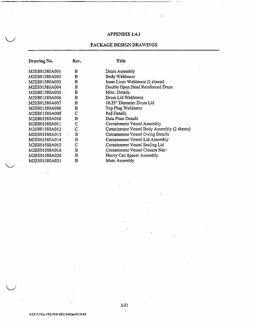
A schematic of the ES-3100 shipping package is shown in Fig. 1.1, and an exploded view of thepackaging components is presented in Fig. 1.2. The packaging design drawings (Appendix 1.4.1) providematerial lists, dimensions, safetycomponents, weldingrequirements, and gasket requirements. The proposedmaximum gross shipping weight of the ES-3100 package with bulk HEU content is 187.81 kg (414.05 lb).
1-1
YILF-717/Ch-11ES-3100 U FSt AR/pc/02-25-05
,' Reinforced Drum Lid
7~Vent Plugs
s/8 GRemovable Top PlugY-12 Patented FireproofImpact Absorbing Insulation(Cast Kaolite 1600)
DRUMBODYCONTAINMENTASSEMBLYVESSEL (CV)ASSEMBLYBOT AD
@ @ CV BO0TTOM PAD C
IU- IALLMATERIAL
CAN (3)
MATERIAL CANHANDLES(3)
'~ CAN PAD (4)
CAN LID (3)
5
I ._. .. ._
Fig. 1.2. Exploded view of the ES-3100 package with bulk IIEU contents.
1-3
YILF-717/Ch-/rIS-3100 IIEU SAR/pc/02-25-O5
- t
The authorized maximum gross weight of the ES-3 100 package is 190.5 kg (420 lb). The ES-3 100 packagingas specified in this SAR is classified as a Category II package (see Appendix 1.4.6). However, since theES-3 100 shipping package may be used for future contents having higher A, values, the package has beendesigned and analyzed to meet the requirements of a Category I package.
1.2.1 Packaging
The main functions of the packaging are containment, shielding, and nuclear criticality safety. Thebulk HEU contents create a maximum decay heat of approximately 0.4 W (Sect. 1.2.3.7 and Sect. 3.1.2);therefore, the packaging does not require any special design features such as coolant valves or continuousventing to meet the thermal requirements of 10 CFR 71.
1.2.1.1 Drum Assembly
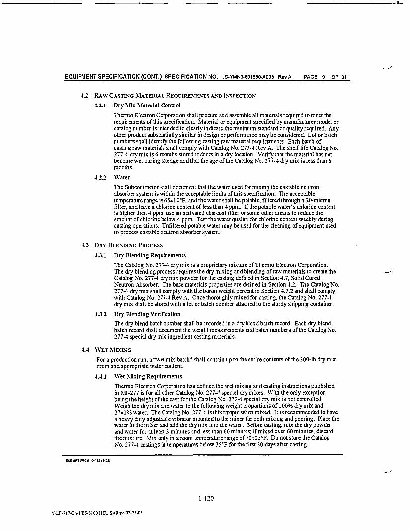
The drum assembly consists of a double open-head reinforced stainless-steel 30-gal drum, archedcover that forms the bottom, arched lid, inner liner, and top plug with cast refractory insulation (Kaolite)[see Drawing M2E801580A00 1, Appendix 1.4.1]. The inside diameter of the drum is 46.36 cm (18.25 in.)with an overall height of 110.49 cm (43.5 in.) including the cover and lid (Drawings M2E801580A004and M2E801580A001, Appendix 1.4.1). The outside diameter of the drum (including the chimes) is49.2 cm (19.37 in.). The drum and lid are made from 16-gauge [-0.152-cm (0.0598-in.)-thick] type 304or 304L stainless steel. A 12-gauge [-0.267-cm (0.105-in.)-thick] stainless-steel arched cover(Drawing M2E801580A005, Appendix 1.4.1) is welded to the double open-head drum to create the bottomof the drum assembly. An inner liner (Drawing M2E801580A003, Appendix 1.4.1) is attached to the drumby an internal flange (angle) that is welded to both the drum and liner. The cavity created by the innerliner for placement of a containment vessel is a three-tier volume. The uppermost tier accommodates thetop plug and has an inside diameter of 37.52 cm (14.77 in.) and is 13.26 cm (5.22 in.) deep(Drawing M2E801580A003, Appendix 1.4.1). The second tier, which accommodates the containment vesselflange, has a 21.84-cm (8.60-in.) inside diameter that is 5.59 cm (2.20 in.) deep (Drawing M2E801580A003,Appendix 1.4.1). The third tier, which accommodates the containment vessel body, has a 15.85-cm (6.24-in.)inside diameter that is 78.31 cm (30.83 in.) deep (Drawing M2E801580A003, Appendix 1.4.1). Anadditional cavity is created between the second and third tier liners. This cavity runs the full length of thethird tier height [78.31 cm (30.83 in.)]. and is approximately 5.99 cm (2.36 in.) thick(Drawing M2E801580A003, Appendix 1.4.1). This cavity is filled with a castable refractory [ThermoElectron Corporation Catalog No. 277-4 (Cat 277-4)] for neutron attenuation purposes. The additionalcavities between the liner and the drum are filled with an inorganic castable refractory material(Kaolite 1600), which acts as both an impact-absorbing and thermal-insulating material.
In accordance with NUREG/CR-3854, Part 4.3 for a Category I shipping package, an acceptablespecification for drums used in any of the component safety groups is U.S. Department of Transportation(DOT) Specification 17C or better. The drum used in the ES-3 100 is fabricated in accordance with thedimensional requirements of MIL-D-6054F and modified as shown on Drawing M2E801580A004(Appendix 1.4.1). Material, fabrication, and quality control criteria are generally equivalent to thoseimposed for a DOT Specification 17C drum. Furthermore, the drum of the ES-3 100 is part of a performance-based package that has been tested and analyzed to demonstrate its ability to maintain confinement andcontainment of its contents under both NCT and HAC. By certifying that the drums used in production meetthe same specifications as those in the compliance tests specified in 10 CFR 71, the drum employed for theES-3 100 is acceptable for a Category I shipping package.
As previously discussed, the drum has been modified by the attachment of an inner liner connectedto the drum by an internal flange welded to both the drum and the liner. Weld studs are attached to the upper
1 4
Y/11-717/Ch-IUES-3 100 HEU SAR'pc/02.25-05
face of the internal flange. The body seams are welded. The following items are conducted in accordancewith Sect. IX of the American Society of Mechanical Engineers (ASME) Boiler and Pressure Vessel Code(B&PVC, Sect. a): welding'piocedures qualification and welders, certification to these qualifiedprocedures. . -
The drum has four circumferential hoops (chimes) formed into the body. The drum has four0.795-cm (0.313-in.)-diam holes equally spaced around the circumference about 3.81 cm (1.50 in.) from thetop rim to relieve pressure in the drum in the event of a thermal accident (Drawing M2E801580A002,Appendix 1.4.1). Plastic plugs (Nylon 6/6, Micro Plastic, Inc., Item Number 62MP0312) are placed intothese holes from the outside to prevent leakage of water into the drum during NCT and storage. The drumis fabricated with a data plate, trefoil data plate, paint, and two lid TID lugs for use with tamper-indicatingdevices (TIDs). The two electrochemically etched data plates are affixed to the exterior of the drum bodyin the locations, and with the methods, indicated onDrawing M2ES01580A031 (Appendix 1.4.1). The trefoildata plate (M2E8015803A010-1) provides the owner's return address, container model, container serialnumber, and the trefoil symbol. The other data plate (M2E801580A010-2) provides the required DOTmarkings-certificate number, maximum gross weight, and "Type B" designation.
The removable lid is attached to the drum body by a flange with eight silicon bronze,5/8-1 1-UNC-2B hex-head nuts [C65 100, American Society for Testing and Materials'(ASTM) F-467] withstainless-steel washers. These nuts are tightened ~onto the weld studs (304 or 304L stainless steel,5/8-11-UNC-2A, ASTM A-493 or F-593) to 40.67 ~ 6.78 N-m (30 1 5 ft-lb) of torque with no sequencespecified.
The top plug is 36.5 cm (14.37 in.) in diarheter'aid 13.41 cm (5.28 in.) in height at the center. Theskin is made from 16 gauge [-0.152-cm (0.0598-in.)-thick] type 3 04 or 304L stainless steel and is filled withKaolite 1600.
The drum assembly also contains three silicone rubber pads. The first pad (CV bottom pad) is placedon the bottom of the innermost liner to support the containment vessel bottom during transport. The secondpad (CV flangepad) is placed on top of the containment vessel lid during transport. The third pad (plugpad)is placed on the top shelf of the mid-liner to cushion the top plug during transport. The locations of thesethree pads are shown on Drawing M2E801580A001 (Appendix 1.4.1), and the dimensions of the pads areshown on Drawing M2E801580A009 (Appendix 1.4.1).
The drum is designed so that lifting can be accomplished with a forklift. It can either be placed onthe tines of the forklift from below, or a pincher'assembly can be placed on the forklift and used to grasp theexterior of the drum assembly. Based on analytical results presented in DAC-EA-801376-A003(Handy 2000) for a similarpackage (the ES-2100), forklift gripping forces of up to 5400 lb can be used withno detrimental effects on the package.
No tie-down devices are integral to the package, nor can any features be used for these purposes.The ES-3100 package is'designed to be shipped in accordance with the safe-secure trailer/safeguardedtransport (SST/SGT) requirements. ' -
1.2.1.2 Insulation
The void area formed by the drum and the attached inner liner is filled with an inorganic castablerefractory material (Kaolite 1600) made by Thermal Ceramics, Inc., which acts as both a thermal insulatingand an impact limiting material. The top plug assembly, which is placed between the containment vessel andthe drum lid, is also filled with Kaolite 1600. This material is a mixture of cement and vermiculite and has
.,:1-5
Y/LF.717/Ch-I/ES-3 100 HEU SAR/pcA02-25-05
Itif
a nominal cured density of -358.8 kg/r 3 (22.4 lb/ft3 ). Additional information regarding the characteristicsand properties of this material is presented in Appendix 2.10.3. Casting takes place while the drum is beingvibrated in an inverted orientation to ensure that the castable material penetrates into all areas in the voidspace formed by the drum and the inner liner and that no considerable voids are formed during this process.The Kaolite material is then baked in a furnace at elevated temperatures [-2600C (5000F)] as prescribed inManufacturing Process Specification, JS-.YMN3-801580-A003, Manufacturing Process Specification forCasting Kaolite 1600 into the ES-3100 Shipping Package, the specification which controls manufacture ofKaolite 1600 for the ES-3 100 (Appendix 1.4.4). The use ofa thermal ceramic material, such as Kaolite 1600,as an impact limiting/thermal insulating material in a Type B fissile material shipping package has beenpreviously used in otherY-12 owned and licensed packages (i.e., ES-2100 and DPP-2). The original decisionto use this material was the result of considerable research. This manufacturing process is protected underU.S. Patent 6,299,950 B I (Byington et al. 2001). The United States Government has rights in this inventionpursuant to Contract No. DE-AC05-84OR2 1400 between DOE and BWXT Y-12.
One of the design goals of Y-12's packaging development program was to build a shipping packageentirely of materials that do not char, bum, or thermally decompose when exposed to the temperatures andconditions associated with HAC [800'C (1475'F)]. Cellulosic fiberboard and polyurethane foams, typicallyused for packaging applications, undergo decomposition when exposed to these HAC thermal conditions.During thermal decomposition, these materials off-gas, producing conditions that are potentially detrimentalto the performance of the package. The hot gases generated within the packaging can transfer heat to innerregions adjacent to the containment closure seals. Under severe circumstances, this process could lead toloss of containment due to overheating of containment seals. The Kaolite material is nonflammable and willnot undergo chemical decomposition at temperatures below 1260'C (2300'F). When Kaolite is heated above1000C (212'F), water vapor from free water contained within the casting will form. Pressurization of thedrum and top plug is prevented by pressure relief holes (vent holes) located near the top of the drum and onthe top center of the top plug (see Sect. 1.2.1.1 and Drawings M2E801580A002 and M2E801580A008,Appendix 1.4.1). The cured Kaolite 1600 material does not decompose, and thus there are no exothermicchemical reactions that could produce superheated off-gasses.
Extensive testing of Kaolite 1600 was performed by the Y-12 Development Division to determinethe performance of the material for this type of application (Oakes, Appendix 2.10.3). Testing showed thatKaolite 1600 has a tremendous ability to absorb shock over a wide range of material densities, curingtemperatures and times, and material temperatures. The 10 CFR 71.73 HAC testing documented in Sect. 2.7demonstrates that Kaolite 1600 is a robust impact limiter and good thermal insulating material for Type Bshipping containers. Post HAC drop testing radiographs of a similar package, the ES-2100, showed someminor cracking of the Kaolite structure in some cases. However, subsequent thermal testing of theseES-2100 packages demonstrated that these cracks were inconsequential to the package's ability to meetregulatory requirements.
Insulation thicknesses within the liner/drum volume adjacent to the side walls of the ES-3100containment vessel are at least 4.27 cm (1.68 in.), with typical thicknesses of approximately 12.10 cm(4.77 in.). Below the containment vessel, the minimum thickness of insulation is 10.05 cm (3.96 in.), andthe top plug, which is above the containment vessel, includes a 12.55-cm (4.94-in.) thickness of insulation.
1-6
Y/1J.717iCh- I ES-3 I00 HEU SAR/pc02.25.05
1.2.13 Shielding
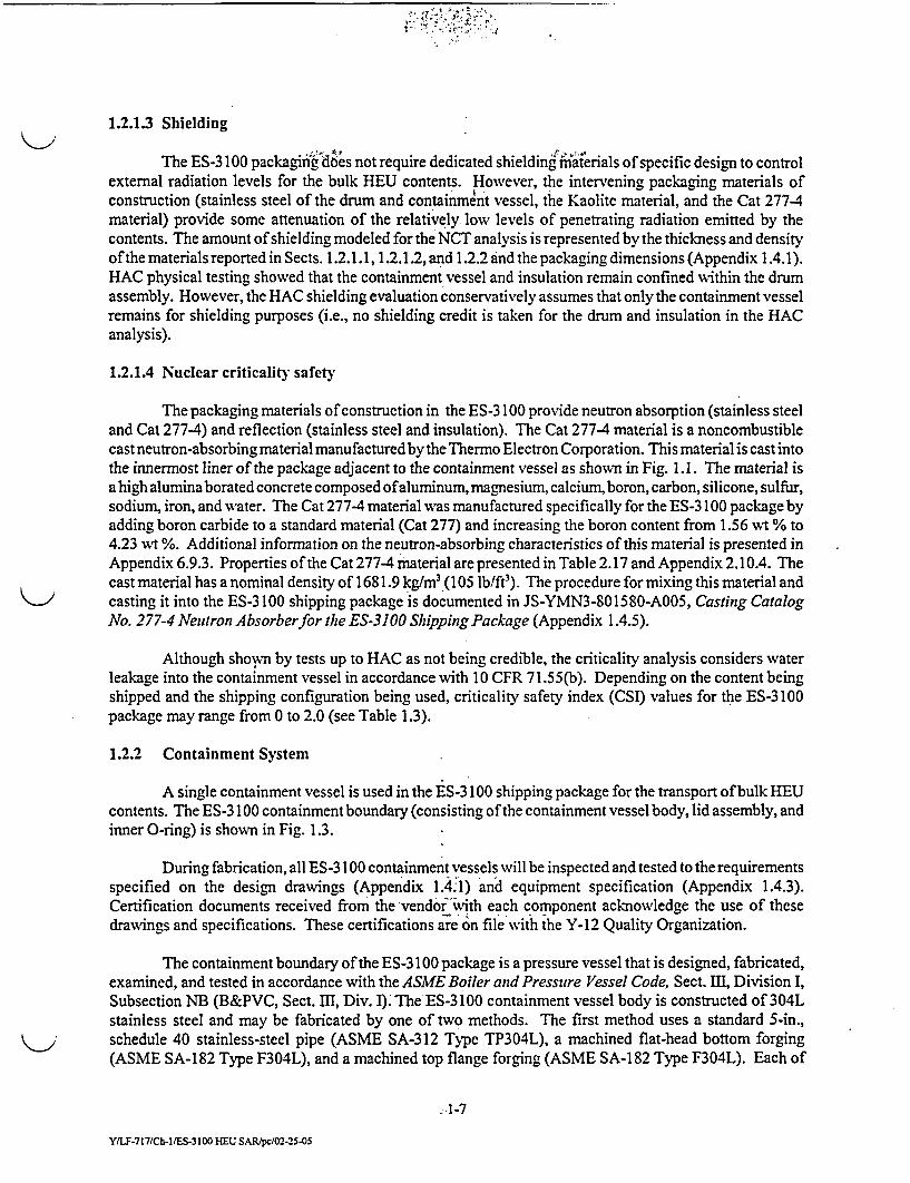
The ES-3 100 packaginig d6es not require dedicated shielding rmiaierials of specific design to controlexternal radiation levels for the bulk HEU contents. However, the intervening packaging materials ofconstruction (stainless steel of the drum and containment vessel, the Kaolite material, and the Cat 277-4material) provide some attenuation of the relatively, low levels of penetrating radiation emitted by thecontents. The amount of shielding modeled for the NCT analysis is represented by the thickness and densityof the materials reported in Sects. 1.2.1.1, 1.2.1.2, and 1.2.2 and the packaging dimensions (Appendix 1.4.1).HAC physical testing showed that the containment vessel and insulation remain confined within the drumassembly. However, the HAC shielding evaluation conservatively assumes that only the containment vesselremains for shielding purposes (i.e., no shielding credit is taken for the drum and insulation in the HACanalysis).
1.2.1.4 Nuclear criticality safety
The packaging materials of construction in the ES-3 100 provide neutron absorption (stainless steeland Cat 277-4) and reflection (stainless steel and insulation). The Cat 277-4 material is a noncombustiblecast neutron-absorbing material manufactured by the Thermo Electron Corporation. This material is cast intothe innermost liner of the package adjacent to the containment vessel as shown in Fig. 1.1. The material isahigh aluminaborated concrete composed ofaluminum, magnesium, calcium, boron, carbon, silicone, sulfur,sodium, iron, and water. The Cat 277-4 material was manufactured specifically for the ES-3100 package byadding boron carbide to a standard material (Cat 277) and increasing the boron content from 1.56 wt % to4.23 wt %. Additional information on the neutron-absorbing characteristics of this material is presented inAppendix 6.9.3. Properties of the Cat 277-4 material are presented in Table 2.17 and Appendix 2.10.4. Thecast material has a nominal density of 1681.9 kg/m3 (105 lb/ft). The procedure for mixing this material and
> casting it into the ES-3 100 shipping package is documented in JS-YMN3-801580-A005, Casting CatalogNo. 277-4 Neutron Absorberfor the ES-3100 Shipping Package (Appendix 1.4.5).
Although sho'%n by tests up to HAC as not being credible, the criticality analysis considers waterleakage into the containment vessel in accordance with 10 CFR 71.55(b). Depending on the content beingshipped and the shipping configuration being used, criticality safety index (CSI) values for the ES-3100package may range from 0 to 2.0 (see Table 1.3).
1.2.2 Containment System
A single containment vessel is used in the ES-3 100 shipping package for the transport of bulk HEUcontents. The ES-3 100 containment boundary (consisting of the containment vessel body, lid assembly, andinner O-ring) is shown in Fig. 1.3.
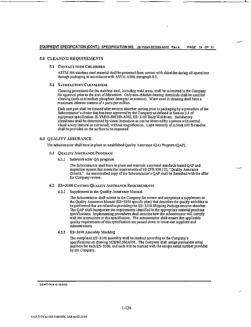
During fabrication, all ES-3 100 containment vessels will be inspected and tested to the requirementsspecified on the design drawings (Appendix 1.4'1) and equipment specification (Appendix 1.4.3).Certification documents received from the vendor''with each component acknowledge the use of thesedrawings and specifications. These certifications are on file with the Y-12 Quality Organization.
The containment boundary of the ES-3 100 package is a pressure vessel that is designed, fabricated,examined, and tested in accordance with the ASME Boiler and Pressure Vessel Code, Sect. III, Division I,Subsection NB (B&PVC, Sect. Im, Div. I). The ES-3 100 containment vessel body is constructed of 304Lstainless steel and may be fabricated by one of two methods. The first method uses a standard 5-in.,schedule 40 stainless-steel pipe (ASME SA-312 Type TP304L), a machined flat-head bottom forging(ASME SA-182 Type F304L), and a machined top flange forging (ASME SA-182 Type F304L). Each of
41-7
YIIY.717/Ch-M/S-3100 HEU SARtpc/02-25-05
I - - - - t
(07.50)
_F//t%%I. .I . . .I -r w-]
- III
iI
i
(32.40)
(31.00)
P , ,_ _ _ _ _ _ _ _ _ _ _ _ I
(.100)- 05.06 ID
Fig. 1.3. Containment boundary of the ES-3100 shipping package.
1-8
Y/LF-717/Ch-I./ES-3100 HEU SAR/pcO02-25-OS
:I
these pieces isjoined with circumferential welds as shown on Drawing M2E801580A012 (Appendix 1.4.1).The top flange is machined to provide two concentric half-dove-tailed O-ring grooves in the flat face, toprovide locations for two 18-8 iainleess steel dowel pins, and to provide the threaded portion for closureusing the lid assembly. The second fabrication method for the ES-3 100 containment vessel uses forging,flow forming, or metal spinning to create the complete body (flat bottom, cylindrical body, and flange) froma single forged billet or bar with final material properties in accordance with ASME SA-1 82 Type F304L.The top flange area using this fabrication technique is machined identically to that of the welded forgingmethod.
The lid assembly, which completes the containment boundary structure, consists of a sealing lid,closure nut, and external retaining ring (Drawing M2E801580A014, Appendix 1.4.1). The containmentvessel sealing lid (Drawing M2E801580A015, Appendix 1.4.1) is machined from Type 304 stainless-steelbar with final material properties in accordance with ASME SA-479. The containment vessel closurenut is machined from a Nitronic 60 -stainless-steel bar with material properties in accordance withASME SA-479. These two components are held together using a WSM-400-S02 external retaining ringmade from Type 302 stainless steel. The sealing lid is further machined to accept a %-16 swivel hoist ringbolt, to provide a leak-checkport between the elastomeric'O-rings, and notched along the perimeter to engagetwo dowel pins. The swivel hoist ring is only intended for use when loading and unloading the containmentvessel. The swivel hoist ring will be removed for shipment. The lid assembly, with the O-rings in place onthe containment vessel body, are joined together by torquing the closure nut and sealing lid assembly to162.70 L 6.78 N-m (120 1 5 ft-lb). The sealing lid portion of the assembly is restrained from rotating duringthis torquing operation by the two dowel pins installed in the body flange.
The use of a design that includes two 0-ring seals permits assembly verification leak testing of thecontainment vessel by measuring the leak rate from the volume between the inner and outer O-rings. Anevacuation port is located between the 0-rings in the containment vessel to facilitate a pressure rise or drop
leakage test following assembly or 10 CFR 71 compliance testing. This port is sealed during transport usinga modified VCO threaded plug. Only the inner O-ring is considered a part of the containment boundary. All0-rings on this containment vessel are fabricated to ASTM D2000, M3BA712A14B13F17.
The inner diameter of the containment vessel is 12.852 cm (5.06 in.) and the usable height inside thecontainment vessel is 78.74 cm (31.0 in.). The wall thickness of the body excluding the flange is 0.254 cm(0.10 in.). The maximum nominal diameter of the containment vessel body is 19.05 cm (7.50 in.). Thenominal thicknesses of the containment vessel's flat bottom is 0.635 cm (0.25 in.). The overall height of thecontainment vessel without the swivel hoist ring is 82.296 cm (32.40 in.). The containment vessel drawingnumber, drawing revision, and serial number are electroetched onto the side of the containment vessel body,as well as onto the top of the sealing lid and the closure nut (Drawing M2E801580A01 1, Appendix 1.4.1).All outer surfaces, unless otherwise specified, are either sand- or bead-blasted, buffed, or sanded to a mattefinish. No penetrations, connections, or fittings into this sealed container exist.
1.2.3 Contents
The ES-3 100 shipping package will be used to ship bulk HEU in the form of oxide (@02, U03, orU308), uranium metal and alloy in the form of solid geometric shapes or broken pieces, and uranyl nitratehexahydrate (UNH) crystals. The ES-3 100 package has been designed to accommodate a maximum of`24 kgof oxide or UNH crystals and a maximum of 36 kg of metal and alloy. The maximum weight of all contents(including convenience cans, can spacers,polyethylenebagging and otherpacking materials) shall notexceed40.82 kg (90 lb). The maximum concentration of uranium isotopes permitted in the ES-3 100 content arelisted in Table 1.1. In addition to the uranium isotopes shown in Table 1.1, transuranic isotopes (with the
-1-9
Y/LF-717/Ch-IIES-3100 HEU SAR/pc/02-25-5
It
Table 1.1. Uranium concentration limits
Uranium isotope Limit232u 0.040 j.g/gU
233U 0.006 g/gU
234 U 0.02 g/gU
235u 1.00 g/gU
236u 0.40 g/gU
238U 1.00 g/gU .
exception of Np) may be present in the contents at a maximum concentration of 40.0 [.g/gU. Theconcentration of Np is limited to 0.003 g/gU.
TEU Oxide
The HEU oxide content in the ES-3 100 package includes UO2 , UO3, and U3 08 Six different oxidecategories have been identified (Appendix 1.4.7). Maximum overall uranium isotopic weight percentsrepresentative of all six oxide categories are presented in Table 1.2. The physical form of all contents isdense, loose powder which may contain clumps. Moisture content in oxide is limited to 3 wt % water (Note:loading restriction #7 in Sect. 1.2.3.8 also applies). Theoretical densities of UO., U308 and U0 3 are10.96 g/cm3, 8.30 g/cm3, and 7.29 g/cm3, respectively. Actual working densities are expected to besignificantly less.
Table 1.2. Bounding uranium isotopic concentrations in oxide
Isotope Bounding limit
232U 40 ppb
' 33 U 200 ppm
234U 2.0 wt %
'35U 97.7 t %'
236u 40.0 vt %
238U 80.0 wvt %
' 23 5Umustbe 220wt%
For convenience, the six oxide categories are referred to as Groups 1-6. These six groups are brieflydescribed below.
Group I oxides are in the form of UO,. Material from this group contains at least 83.0% uraniumby weight and displays typical isotopic content (•0.977 g235U/gU, •0.014 g 234U/gU, •0.010 g136U/gU,•0.040 pg232U/gU, •50.0 p1g233U/gU with the balance of the uranium being 238U).
1-10
Y/.-717/Ch-I/ES-3100 HEU SARIpcIO2-25-05
- Group 2 oxides are in the form of UO,. Material from this group contains at least 20.0% uraniumby weight and displays typical isotopic content (g0.977 g 235U/g U, •0.014 g 234U/g U, 0.0 10 g 236U/g U,•0.040 pg 232U/g U, •50.0 Pg 233U/g U with the balance of the urani'um being 238U).
Group 3 oxides are contaminated with up to 40 pg Pu/g U and are in the form of UO1 . Material fromthis group contains at least 83.0% uranium by weight and displays typical isotopic content for uranium(•0.977 g 235U/g U, •0.014 g 234U/g U, •0.010 g `6U/g U, •0.040 pg 232U/g U, •50.0 pg 233U/g U with thebalance of the uranium being 2381U).
Group 4 oxides are in the form of U308. Material from this group contains at least 83.0% uraniumby weight and displays typical isotopic content (50.977 g 235U/g U, •0.014 g 234U/g U, •0.010 g 236U/g U,•0.040 pg 232U/g U, •50.0 pg 233U/g U with the balance of the uranium being 238U).
Group 5 oxides are in the form of UO,. Material from this group contains at least 20.0% uraniumby weight and displays typical isotopic content (•0.977 g 233U/g U, •0.014 g 234U/g U, •0.010 g 236U/g U,•0.040 pg 232U/g U, •50.0 pg 233U/g U with the balance of the uranium being 238U). This material maycontain considerable activity in the form of unspecified beta emitters.
Group 6 oxides are in the form of UO. Material from this group contains at least 20.0% uraniumby weight and may display unusually high isotopic concentrations of 233u, 234U, and `6U (•0.977 g 235U/g U,•0.020 g 234U/g U, •0.40 g 236U/g U, •0.040 pg 232U/g U, •200.0 pg 233U/g U with the balance of the uraniumbeing 238U).
HEUJ Metal and Allov
HEU metal and alloy may be in the form of solid geometric shapes. Solid shapes may include thefollowing:
1. spheres having a diameter no larger than 3.24 in. (maximum of two spheres per convenience can);
2. cylinders having a diameter no larger than 3.24 in. (maximum of one cylinder per conveniencecan);
3. square bars having a cross sectionf no larger than 2.29 in. x 2.29 in. (maximum of one bar perconvenience can); and'
4. slugs having dimensions of 1.5 in. diameter x 2 in. tall (maximum of 10 per convenience can).-. ' '' 5 1
HEU bulk metal and alloy contents not covered by the geometric shapes category specified abovewill be in the broken metal category, and will be so limited.
HEU bulk metal and alloy contents in the broken metal category may be of unspecified geometricform. HEU bulk metal and alloy in this category may also be of a specific shape where onie or more of thecharacteristic dimensions vary from piece to piece (i.e., the height, width, length,-radius, etc.). Forpyrophoric considerations, HEUmetal and alloyshipped in the ES-3 100 must meet the followingrestrictions:
1. no metal pieces can be of a size or shape with a specific surface area >1.00 cm2/g;
2. no metal pieces can weigh less than 50 g; and
3. material forms such as foils, turnings, and wires are not allowed for shipment.
'.1-11
Y/TJ.717/Cb-I/E5.3100 lEU SAR~PC/02-2S-05
- I IL
It may be possible to ship large irregular pieces of HEU metal or alloy (that do not meet thedefinition or size restriction of one of the solid geometric shapes discussed above) as a geometric shape asopposed to broken metal. In order to do this, additional criticality safety evaluations would be required todemonstrate that these contents are bounded by one of the solid geometric shapes evaluated in this SAR (i.e.,spheres, cylinders, square bars, and slugs).
Uranvl Nitrate Crvstals
Uranyl nitrate hexahydrate (UNH) crystals are formed by dissolving uranium metal or any of theuranium oxides in nitric acid. It crystalizes from solution as the well-formed yellow UNH[UO2(NO3)2*6HI01. The theoretical density of UNH crystals is 2.79 g/cm3; however, the working densitieswill be less.
1.2.3.1 Radioactive/fissile constituents
Fissile material mass loading limits for the contents of the ES-3 100, as determined by criticalityanalyses, are presented in Table 1.3. For the ES-3 100 package with bulk HEU content, the maximum numberof A2s is 290.26 (at 50 years) and the maximum activity is 0.3112 Tbq (at 10 years) [Table 4.4].
1.2.3.2 Chemical and physical form
The fissile material contents are in solid (HEU metal or alloy), crystalline (UNH) or powder (HEUoxide) form. Some moisture (up to 3%) may be present in the HEU oxide material, thereby making the oxidecontent clump together.
1.2.3.3 Reflectors, absorbers, and moderators
The reflectors, absorbers, and moderators present in the ES-3 100 package are those associated withthe materials of construction. For example, the thermal insulation acts as a neutron reflector to the contentsof a single package and as a neutron moderator in an array of packages. The degree of neutron moderationis a function of the hydrogen content in the Kaolite 1600 and Cat 277-4 materials. The stainless-steelmaterials of the containment vessel and the drum also act as neutron reflectors to the contents of a singlepackage but act as neutron absorbers in an array of packages. The nuclear properties of the materials ofconstruction and of the contents are important and have been taken into account in the criticality safetyevaluation (Sect. 6). In addition to the materials of construction in the ES-3 100 shipping package mentionedabove, the Cat 277-4 material has been specifically added to the ES-3 100 package for the purpose ofenhancing the neutron absorption characteristics for safety purposes (see Sect. 6 for additional discussionof the neutron-absorbing characteristics of this material).
1.2.3.4 Shipping configurations
Convenience cans constructed of stainless steel or tin-plated carbon steel are used to hold the HEUcontents for shipment in the ES-3 100 package and to assure that the inside of the containment vessel doesnot become contaminated with HEU under NCT. The convenience cans used in the ES-3100 package musthave an outer diameter less than 12.7 cm (5 in.) and a maximum height of 25.4 cm (10 in.). Some contentsrequire the use of can spacers (see Table 1.3). These can spacers are thin-walled stainless-steel cans filledwith Cat 277-4 material (Drawing M2E801580A026, Appendix 1.4.1). Each convenience can and spacermay be equipped with a stainless-steel band and nylon-coated wire to facilitate loading and unloadingoperations. Silicone rubber pads may also be used between convenience cans to dampen vibration andminimize contact between metal components. Any combination of these convenience cans will be allowed
1-12
Y/LF-717/Ch-I/ES-3100 HEU SAR&pc/02-25-05
� 1. ..... � I.- !'�, -- ,.
Table 1.3. Authorized content a and fissile mass loading limitsbc' for the ES-3100
Content -Cat 277-4CotetNo spacers, -S
Crnteio Enrichment CSI |3 5u (kg) can spacers,descripion 23U (kg)
Solid HEU metal Spheres s 100% ' - '0.0 16.946 32.983or alloy Cylinders s 100% 0.0 12.000 18.000
HEU oxide > 20%, s 100% - 0.0 21.124' Spacernotreq'dUNH crystals > 20%, • 100% 0.0 11.303' Spacer not req'd
bHEU in solution form is not permitted for shipment in the ES-3 100. 7 -All limits arc expressed in kg "U unless otherwise indicated.Mass loadings cannot be rounded up. ' K .Cat 277-4 can spacers as described on Drawing No. M2E801580A026 (Appendix 1.4.1).-Geom'etries of solid shapes are as follows:- Spheres are no larger than 3.24 in. diameter: maximum of 2 spheres per can.- Cylinders are no larger than 3.24 in. diameter: maximum of I cylinder per can.- Square bars are no larger than 2.29 in. x 2.29 in. (cross section): maximum of I bar per can.- Slugs are a maximum of 1.5 in. diameter x 2.0 in. tall: a maximum of 10 per convenience can where the actual number permitted is
restricted by the stated loading limit. . .I This 3
'U fissile mass limit corresponds to 24 kg of material.
.1-13
Y/LF.717/Ch-IIES-3100 HEU SAR/pCI02.25-05
in a single package, as long as the total height of the stack-up (including spacers, if required) does not exceedthe inside working height of the containment vessel [78.74 cm (31 in.)]. If can spacers are required, no morethan one-third of the total HEU content mass limit shown in Table 1.3 may be placed in any singleconvenience can.
Five typical shipping configurations inside the ES-3 100 containment vessel are shown in Fig. 1.4.The shipping configurations shown in Fig. 1.4 utilize 4.25 and 5-in.-diam convenience cans of variousheights (4.88, 8.75, and 10 in.). Although any combination of convenience cans that will fit inside theinternal volume of the containment vessel may be used, content forms will not be mixed in a single package(i.e., HEU oxides may not be shipped with HEU metal). Empty cans and/or stainless-steel scrubbers maybe used to fill the void space at the top of the containment vessel. If empty cans are shipped, a minimum0.32-cm (0.1 25-in.)-diam hole must be placed through the lid to prevent over-pressurization of the can in theevent of a thermal accident. In addition, these empty cans must be placed on top of the loaded cans. Inconfigurations not requiring can spacers for criticality control, can spacers may be shipped for convenienceif placed on top of loaded cans in the containment vessel.. The H EU contents may be bagged or wrapped inpolyethylene, and the convenience cans may also be wrapped in polyethylene to further reduce the possibilityof contamination (see Sect. 1.2.3.8 for mass limits on packing materials such as polyethylene bagging). Insome shipping configurations, silicone rubber pads will be placed between the convenience cans to reducevibration.
1.2.3.5 Maximum normal operating pressure
As defined in 10 CFR 71.4, the maximum normal operating pressure is the maximum gauge pressurethat would develop in the containment system in one year under an ambient temperature of 380 C (1000F) instill air, with appropriate insolation in the absence of venting, external cooling by an ancillary system, oroperational controls during transport. Under these conditions, the maximum normal operating pressure inthe ES-3100 containment vessel would be 122.63 kPa (17.786 psia). In comparison, the design internalpressure of the containment vessel is 801.17 kPa (116.2 psia). The design internal pressure is aconservatively assumed value that was assigned for the purpose of the ASME code calculations inAppendix 2.10.1.
1.2.3.6 Maximum and minimum weight
The maximum gross shipping weight for the ES-3 100 package is 190.5 kg (420 lb). The proposedmaximum gross shipping weight of the ES-3 100 package with any proposed content is 187.81 kg (414.05 lb)[Table 2.8]. The total weight of the tested ES-3100 units ranged from 157.4 to 203.7 kg (347 to 449 lb)[Table 2.9].
The maximum authorized weight of HEU in the ES-3 100 shipping package is 36 kg (79.37 lb). Thislimit has been established as a bounding case for the maximum structural, thermal, and containment limitfor the package. A minimum HEU content weight of 2.77 kg (6.11 lb) has been established as the lowerbounding case for the maximum structural, thermal, and -..ntainment limit for the package. This minimumcontent weight corresponds to the lowest simulated payload weight used during the prototype testing of theES-3 100 package. Actual mass restrictions for the various contents based on the criticality analyses are listedin Table 1.3. The maximum allowable payload weight of any configuration, including packing components(convenience cans, polyethylene bags, can spacers, etc.), is 40.82 kg (90 lb). The payload weight (includingconvenience cans, silicone rubber pads, can spacers, and the HEU mockup) used in the ES-3 100 packagetests ranged from a minimum of 3.6 kg (8 lb) to a maximum of 50.3 kg (111 lb). ES-3 100 shipping packageweights are discussed in greater detail in Sect. 2 and are broken down into individual component weights inTables 2.8 and 2.9.
1-14
Y1LX.717ICh-fES31cOG lEU SARIPC/O2.25-05
C ( (
.. . .7
.I.,
lI I : i
-5 THREE CANS050 BY 1 ON TALL
-1 THREE CANS04.25 BY 1 0 TALL
- -2 THREE CANS.04.25 BY 8.75W TALL
&MWO SPACERS
-3 SIX CANS04.25 BY 4.88W TALL.
-4 FIVE CANS04.25 BY 4.88' TALL& FOUR SPACERS
Fig. 1.4. Typical shipping configurations inside the ES-3100 containment vessel.
As shown in Sect. 3.1.2, the conservatively calculated maximum heat generation rate ofthe contentsis approximately 0.4 W. The ES-3 100 package was designed for a maximum heat load of 20 W. Thermalanalyses have been performed assuming heat sources of 0.4, 20, and 30 W in the ES-3 100 containment vessel(Appendix 3.6.2).
1.2.3.8 Loading restrictions
Loading restrictions based upon the results of the criticality safety calculations presented inSect. 6.2.4 and additional limitations on packing materials outlined in Sect. 3 are as follows:
(1) HEU fissile material to be shipped in the ES-3 100 package must be placed in stainless-steel or tin-plated carbon steel convenience cans. The conveience cans must have an outer diameter less than12.7 cm (5 in.) and a maximum height of 25.4 cm (10 in.). Any closure on the convenience can isallowed.
(2) Any combination of convenience cans is allowed in a single package, as long as the total height(including silicone rubber pads and can spacers, if required) does not exceed the inside workingheight of the containment vessel (approximately 31 in.).
(3) In situations where empty convenience cans are shipped in the package, they must be placed on topof the loaded cans, and a minimum 0.32-cm (0. 125-in.)-diam hole must be placed through the lid toprevent over pressurization of the can.
(4) The concentration of uranium isotopes in the content is limited as shown in Table 1.1.
(5) For pyrophoric considerations, HEU loading is further restricted to metal piece sizes with a specificsurface area not greater than 1.00 cm2/g or a piece weight not less than 50 g, whichever is morerestrictive. Furthermore, foils, turnings, and wires, which can easily have much higher specificsurface areas, are not permitted for shipment.
(6) The content shall not exceed "per package" fissile material mass loading limits specified in Table 1.3based on the CSI. Where can spacers are required for a "per package" mass loading, the quantityof fissile material located between any two spacers shall not exceed one-third of the mass loadinglimit in Table 1.3.
(7) The total amount of hydrogen contained in both the package content (including absorbed moistureor hydration molecules of the fissile content) and the water if the containment vessel were to floodshall not exceed an average density of 0.1 1 17 g/cm3 inside the free volume of the containment vesselnot occupied by dry package content. The package content is defined as the HEU fissile material,the convenience cans and can spacers, and the associated packing materials (plastic bags, pads, tape,etc.) inside the ES-3 100 containment vessel.
(8) The mass of packing materials that off-gas (i.e., polyethylene bagging, silicone rubber, etc.) usedinside the ES-3 100 containment vessel is limited to 500 g (Sect. 3.1.4.2) or the average density limitspecified in Item 7 above, whichever is more restrictive. In addition, if convenience cans having adiameter greater than 4.25 in. are used, no packing materials that off-gas at temperatures aboveambient may be used inside the containment vessel.
1-16
Y/LF-717/Ch-IIES-3100 HEU SAR/pc/02-25.05
1.2.4 Operational Features
The ES-3 100 package is a Type B fissile material package designed in accordance with DOT andNRC regulations. These regulations require that the package be operated without undue risk to the public,even in the event of a severe accident, and that the dose rate and nonfixed radioactive contamination on theexternal surface of the package conform with 49 CFR 173.441 and 173.443, respectively. Theserequirements are translated into the designs for the containment, shielding, and nuclear criticality safety ofthe contents when subj ected to NCT and HAC. Designs for containment, shielding, and nuclear subcriticalitysafety are supported by operational procedures for loading, unloading, and refurbishing to ensure that thosedesign features are used and maintained in a manner commensurate with their intended function. Drop tests,crush tests, puncture tests, thermal tests, and water immersion tests (Sects. 2.6 and 2.7) show that the drumassembly maintains the insulation and the containment vessel in their intended configurations when subjectedto NCT and HAC.
The decay heat generated by the contents (maximum of approximately 0.4 W) is negligible for apackage of this size (Sect. 1.2.3.7 and Sect. 3.1.2).
Design features that provide shielding, containment, and nuclear criticality control perform thesefunctions in apassive manner. No valves, connection's, gauges, active coolants, or operationallypressurizedparts are integral to the ES-3 100 package.
1.3 GENERAL REQUIREMENTS FOR ALL PACKAGES
This section demonstrates compliance with 10 CFR 71.43(a) and (b), "General Standards for AllPackages."
1.3.1 Minimum package size
Requirement. The smallest overall dimension of a package may not be less than 10 cm (4 in.).
Analysis. The drum's outside diameter(including the chimes orrollingrings) is49.2 cm(19.37 in.),and the outside height including the lid is 110.49 cm (43.5 in.). The minimum outside diameter of theES-3 100 containment vessel is 13.36 cm (5.26 in.), and the overall height is 82.30 cm (32.4 in.). Therefore,the packaging meets this requirement.
1.3.2 Tamper-indicating feature
Requirement. The outside of a package must incorporate a feature, such as a seal, that is not readilybreakable and that, while intact, provides evidence that the package has not been opened by unauthorizedpersons.
Analysis. The removable drum head is attached to the body by eight 5/8-11 -UNC-2B silicon bronzenuts and 5/8-in. nominal washers. Two 0.51-cm (0.20-in.)-thick lugs with 0.953-cm (0.375-in.)-diam holesproject through slots in the drum lid and provide attachment for wire-type tamper-indicating devices (TIDs).These TIDs consist of a stainless-steel cable with an aluminum crimp closure or equivalent. The requirementis satisfied by the TIDs, which are installed as specified in Sect. 7.1.2.2. The seal is only required when HEUis in the package. It is not required for empty shipments.
B Change the btle of drawing M2E-801580-A001 from Confinement Boundary Assemblyto Drum Assembly. Changethe title ofthis specificaton from ES-3100 Confinement Boundary Drums to ES-31 0 Drum Assembly. Deletedreference to draving M2E-801580-A009, Pad Details. Added the reference to drawings M2E-801580-AO10, DataPlates and M2E-801580-A031, Main Assembly. Changed the wording in the frst paragraph of Section 3.3. InSection 3.2 removed Capacitive Discharge (CD). Changed the reference from OO-PP-1211 ProcurementSpecification to Procurement Specification throughout; 'Change reference of the neutron poison from BoroBond4to Catalog 277-4 in Sections 3A and 3.5 and changed the Specification reference from YSYMN3-801580-A004 toYS-YMN3-801580-A005. Also added new Section 3.6 Weldng Documentation Submittals.
SIGNATURE IIATF SIGNATURE BATEpPflPqED BYIIVff
G.A.Bington 2/11/05 D. J.Etler 2.11/05DISCrLM. MANAGER PRs~xCi W.E
D.P. Sooter 11Feb06S G. A.Byinon 2.11/05DES$ON wnfflcxnIO OGIEP ~ 4Ef
~This document has been has been reviewed by a Y.12 ADC and UNCI R.O and has been determined tobeUNCLASSIFED and not UNCI. This review does not constitute clearance for public release.
Drawing Number TitleM2E-801580-A001M2E-801580-A002M2E-801580-A003M2E-801580-A004M2E-801580-A005M2E-801580-A006M2E-801580-A007M2E-801580-AOOSM2E-801580-A010M2E-801580-A031
Drum AssemblyBody WeldmentInner Liner WeldmentDouble Open Head Reinforced DrumMisc. DetailsDrum Lid WeldmentDrum LidTop Plug WeldmentData PlatesMain Assembly
EXEMPT FROM i0-155
1-66
YalF.71 7/Ch-I/ES-3 100 HEU SAP.'pe/02-25.05
SP Pc RION W P[ W
r I A I ktJS-YMN3-801580-A002 BEQUIPMENT S PECIFICATIION ;
lo1-15-03 02111105ES-3100 DRUM ASSEMBLY PAGE
Y-12 1 OF 6
1.0 SCOPE
This specification, the Procurement Specificatiodn for the ES-3100 Drum Assembly,specifications JS-YMN3-801580-A003 and .S-YMN3-801580-A005, the Company'sdrawings, and the referenced codes and standards in section 2.0 of this specification state therequirements for the procurement of materials and components, fabrication, inspection,examination, assembly, and testing of the'Druim Assembly for the ES-3 100 shipping package.If conflicting requirements appear between the Cornpany's documents, and the standards listedin section 2.0 of this document, the Seller shall immediately notify the Company, so that thesecan be resolved. The Seller shall provide the number of completed assemblies specified in thepurchase order.
This specification describes the applicable procedures to be followed in the fabrication,welding, examination, inspection, quality assurance, and documentation requirements for aDrum Assembly used in a Type B nuclear shipping package.
The Drum Assembly shall be manufactured in accordance with those paragraphs of theAmerican Society of Mechanical Engineers (ASME) Boiler and Pressure Vessel Code, SectionVIII, Division 1 that are specified in this document. The Drum Assemblies are not pressurevessels and are not to be hydrostaticallytested, nor are they to be stamped. If the Seller doesnot have certificate of authorization from the ASME to apply the U stamp, the Seller shall befamiliar with, and capable of meeting those requirements in Section VIII, Division 1 of theASME Boiler and Pressure Vessel Code that are referenced in this specification.
Company specification JS-YMN3-801580-A003 gives requirements for casting Kaolite, andJS-YMN3-801580-A005 gives requirements for casting Catalog No. 277-4 in the drum asshown on the Company's drawings.
2.0 APPLICABLE CODES AND STANDARDS
The Drum Assembly shall be fabricated inspected, and tested according to the designdrawings, and the portions of the codes, standards, and regulations to the extent describedherein.
- American Society of Mechanical Engineers, Boiler and Pressure Vessel Code, SectionVIII, Division 1, 2001 Edition with 2002 and 2003 addenda
- American Society of Mechanical Engineers, Boiler and Pressure Vessel Code, Section II,Parts A and C, 2001 Edition and 2002 and 2003 addenda
EXEMPT FROM 10-155
1-67
Y/LF.717,Ch- I/ES-3 I300 HIEU SAR/pc/02-25-05
II
EQUIPMENT SPECIFICATION (CONT.} A11.VMNI.SMfl¶Rfl.Aflf Rawu A PAGE 2 MC 6-1 -
- American Society of Mechanical Engineers, Boiler and Pressure Vessel Code, Section V,2001 Edition and 2002 and 2003 addenda
- American Society of Mechanical Engineers, Boiler and Pressure Vessel Code, SectionIX, 2001 Edition and 2002 and 2003 addenda
- American Society For Nondestructive Testing, No. SNT-TC- IA-1 992, RecommendedPractice for Nondestructive Testing Personnel Qualification and Certification, Dec 1992
- Military Standard, MS27683, Drum, Metal-Shipping and Storage 16 to 80 Gallons
- American Society For Testing Materials, ASTM A 35Q-99e1, Standard Practice forCleaning, Descaling, and Passivation of Stainless Steel Parts, Equipment and Systems.
All references to the ASME Code in this document are to the ASME Boiler and PressureVessel Code, the 2001 Edition with the 2002 and the 2003 addenda.
3.0 DETAILED REQUIREMENTS
Detailed dimensional requirements and the materials of construction are called out on theCompany's drawings. Additional requirements for materials are given in section 3.1 of thisspecification. The Seller shall be responsible for determining stock sizes so that the finishedmachined components meet the dimensions, tolerances and surface features called out on theattached drawings.
Weld symbols are provided on the Company's drawings indicating for eachweld the type ofweld and dimensions of weld. Additional welding requirements are stated in section 3.2 of thisspecification
Any material substitution or any other deviation from the requirements shown on theCompany's drawings, or stated in the Company's document is not permitted without the Sellersubmitting a written request for waiver or deviation, and the Company's written approval (seethe Procurement Specification for the ES-3 100 Drum Assembly).
The assembled Drum Assembly shall be marked according to the Company's drawings. TheCompany will assign permanent serial numbers for each Drum Assembly. Drum Assembly'srecords may be maintained based upon a temporary serial number assigned by the Seller. Thetemporary serial number for the Drum Assembly shall be cross-referenced to the DrumAssembly's permanent serial number.
The following additional requirements apply as follows:
EXEM PT FROM 10-155
1-68
Y/LF.717,Ch- IES-3 100 HEU SAR'PC!02-25-05
EQUIPMENT SPECIFICATION{CONT.}-L J S-YMN3-801580.A002. Rev. B PAGE 3 OF 6
3.1 Materials
Except for the weld studs, documented Certified Material Test Reports (CMTR's) shall beprovided to the Company for all materials used in weldments for the fabrication of the DrumAssembly, including weld filler metal. The CMTR's shall be traceable to heat numbers andshall demonstrate compliance with the SA or SFA material specifications called out. For allother the materials documented Certificates of Compliance shall be provided to the Companycertifying that the materials provided comply the requirements stated on the Company'sdrawings and specifications. See the Procurement Specification for the ES-3 100 DrumAssembly for specific documentation requirements.
The markings on the weldment materials shall not be removed until after all weld examinationis complete. Note that the heat numbers of base metals and weld filler are required on all weldexamination reports (see section 3.3 of this specification).
The weld filler metal used in the fabrication of the Drum Assemblies shall be procured tocomply with the SFA specifications of Section II, Part C of the ASME Code that are stated inthe Seller's welding procedure specifications. -Weld filler metal shall be procured traceable toheat numbers, and Certified Material Test Reports shall be furnished to the Company for eachheat of weld wire filler. The control of weld filler by the Seller shall permit a weld examiner tobe able to determine the heat number of the weld filler used in any weld on the DrumAssembly.
Prior written approval of the Company shall be obtained for any weld repair on materials, andthe weld repair areas shall be noted in a sketch supplied with the CMTR for the material thatwas weld repaired. Note that depending on the specific defect in a specific material, theCompany may or may not approve the weld repair, even if it is permitted by the materialspecification.
3.2 Weldin-
All welding shall be done in accordance with welding procedure specifications that are written andperformance qualified in accordance with the ASME Code, Section IX. All welders shall be.performance qualified to weld using these procedures, and their qualifications documented inaccordance with the ASME Code, Section IX. The welding fabrication requirements stated in theASME Code, Section VIII, Division 1, paragraphs UW-26 through UW-48 shall be met. TheInspector referenced in these paragraphs shall be an individual or individuals that are employed bythe Company or subcontractors to the Company.
All butt welds in rolled sheet, pipe and angle joints shall be full penetrationbutt welds. With theexception of the seam welds in the drum body, all welds shall be done by the GTAW, GMAW,PAW or stud welding process.
EXEMPT FROW 10-155
1I-69
Y/LF.717/'Cha-VES-3100 HEUl SAR.'pc/02-25-05
R)HIPMPKITSPPOPICATION (CONT-1 _MVIANIAMR(I.Anfll Rau R PAI= A 4nCAFOIJIPMFMT SPECIFICATION (CONTh J�VMNI2.Rfl1�Rfl.Aflfl7 �aiv � DAt� A fl� �
Welders performing two or more welds in one day that are rejected shall be subject to be re-qualified to the appropriate welding procedures, see Section IX, and paragraph QW-320 of theASME Code.
3.3 Weld Examination
A qualified weld examiner using a written weld examination procedure shall visually examineall designated welds. Weld examiners shall be currently certified to perform visual weldexamination in accordance with their employers written practice, which must be in accordanceeither SNT-TC-IA (2001 Edition), "Personnel Qualification and Certification inNondestructive Testing;" or ANSI/ASNT CP-189 (2001 Edition), "ASNT Standard forQualification and Certification of Nondestructive Testing Personnel;" published by theAmerican Society for Nondestructive Testing. The weld examination procedure shall meet therequirements of the ASME Code, Section V. The weld examination procedures, the weldexaminers qualifications, and the weld examination reports shall be submitted to the Company.
Written weld examination reports for all weld examination shall include: the Drum Assemblyserial number, a weld map showing the location of the weld, the welder's name, the examiner'sname, the time and date of the weld examination, the examination procedure number used, theWPS number, the heat numbers of the materials joined, the heat number of the weld filler, andthe examiner's remarks. The examiner's remarks shall include the results of the examination,and acceptance or rejection of the weld based on the stated criteria and include a descriptionand sketch showing the location of any defects found. Weld examination reports shall besubmitted to the Company as stated in the Procurement Specification for the ES-31 00 DrumAssembly.
The acceptance criteria for joint fit-up and alignment, and for visual examination of welds aregivenin the ASME Code, Section VIII, Division 1, paragraphs U'TV-31 through UW-36. Inaddition, any visible defects such as lack of fusion, lack of penetration, linear or crack likedefects, and visible porosity, shall be cause for rejection.
If a weld is rejected, the area may be weld repaired by the Seller and re-examined After twounsuccessful repair attempts, the Company shall be notified for approval to perform morerepair attempts. The Company may, at its option, choose to reject further repair efforts andrequire that a replacement part be fabricated.
If penetrant examination of welds or materials is performed the materials used in theexamination shall be specifically recommended by their suppliers for use with austeniticstainless steels, and copies of the certification of contaminant content of materials used (seeSection V, Article 6, T-64 1) shall be supplied to the Company with the examination reports.
EXEMPTFROM 10-155
1-70
YILF-717iCh.1/ES.3 100 HIEU SAR~pc'02-25-05
EQUIPMENT SPECIFICATION (CONT.) JS-YMN3-801580.A002. Rev. B PAGE 5 OF 6
3.4 Cleaninr and Passivation
Cleaning procedures for the stainless steel, including weld areas, shall be submitted to theCompany for approval prior to the start of fabrication, see the Procurement Specification forthe ES-3100 Drum Assembly. Only non-chdoride bearing chemicals shal be used for cleaning(such as trisodium phosphate detergent or acetone). Water used in cleaning shall have amaximum chlorine content of 0.5 parts per million.
Finished components awaiting assembly and asseiblies shall be free of dirt, debris, foreignobjects, cutting fluids, metal chips, grinding residue, and other foreign substances. The Sellershall clean, cover, and protect parts and subassemblies from becoming dirty while in storage,and to the extent practical, in the shop environment while in work.
After final machining and examination of all welds except the attachment welds for the drumbottom and the closure weld on the top plug, and prior to filling with Kaolite and Catalog No.277-4 (see JS-YMN3-801580-A003 and JS-YMN3-801580-A005), clean and passivate allstainless steel surfaces of the Drum Assembly in accordance with ASTM A 380. After theclosure weld on the top plug weldment and the attachment weld on the drum bottom areexamined, clean and locally passivate the weld areas and heat affected zone areas.
3.5 Dimensional Inspection Reports
Straightening, flattening, and forming by mechanical or thermal means of some features andcomponents after welding may be required to ensure proper assembly. The surfaces of areas ofthe weldment that have been worked shall be visually examined to ensure that no cracks arepresent or that the weldment has been degraded. Adjacent welds to these areas shall also be-visually examined. The acceptance criteria are that no cracks are found. The areas worked andthe visual inspections shall be noted on the dimensional inspection report. This work andexamination shall be performed prior to the installation of Kaolite or Catalog No. 277-4.
After all testing, inspection and final machining, the Drum Assemblies shall be dimensionallyinspected. The dimensions, and features such as flatness, runout, etc, to be inspected areindicated on the Company's drawings. A written inspection report shall be prepared, andsubmittedto the Company as stated inthe Procurement Specification for the ES-3100 DrumAssembly. -. .
~.
EXEMPTFROM 10-155
1-71
YtLF-71 7Ch- I/ES-3 100 HiEU SAR/pc'02.25.05
POIJIPMFNT SPFCIFICATION (CONT.) JS-YPAN2.9flISH-AM Rpv R PAGE Ft 0 F AEQUIPMENT SPECIFICATION (CONTi 1S.YMN�n15Rfl.Afln2 R�v R PA�F R flF �
3.6 Welding Documentation Submnittals3.6.1 Submittal of the following are required with the bid unless the current revisions of
these submittals have been previously approved by the Company. Submittals thatdo not demonstrate compliance with this specification will be cause for rejection ofthe proposal.
3.6.1.1 Typical welding procedure specifications (`WPS) for the applicable code.3.6.1.2 Procedure qualification records (PQR).3.6.1.3 Typical welder performance qualification (WPQ) records for the appropriate
code.
3.6.2 Submittal of the following documents are required prior to welding unless thecurrent revisions of these submittals have been previously approved by theCompany.
3.6.2.1 Welding Procedure Specifications (WPS).3.6.2.2 Procedure Qualification Records (PQR).3.6.2.3 Welder Performance Qualification (WPQ) records, including evidence of
process usage updates.3.6.2.4 Visual examination and nondestructive examination procedures.3.6.2.5 Certification records of examination personnel.3.6.2.6 Certified Material Test Reports.
3.6.3 To facilitate prompt review by the Company of the Seller's weld program, thewelding documentation required above shall be submitted electronically in Adobepdf format either on compact disk (CD) or by email. All information submittedshall reflect the Seller's most current documentation. Upon review and approval ofthe documentation, the Seller will be notified.
3.6.4 If the latest revision of the Seller's welding documentation required above has beenpreviously submitted electronically and reviewed and approved by the Company,this shall be so stated with the offer. The Seller shall submit a detailed list of thewelding documentation to be used for this contract including title, revisions/dates,type components to be used on (i.e., piping, structural, sheet metal, etc.) andindicate the previous contract and approval date. The Company will then review thedocumentation for applicability on the new contract and approve or comment.
3.6.5 If changes have occurred since the last approval of the welding documentation, inaddition to the list of welding documentation that they propose to use the Sellershall submit those documents that have changed. The Company will then review,comment and/or approve the Seller's documentation.
B Included the requirements for a Containment Vessel that was fabricated by weldng a forged bottom, a forgedtop flange and a cylindrical shell as shown on the revised drawing, M2E801580A01Z Rev B.
C In all locations removed the references to the Procurement Specification document number OO-PP-1210.Modified the Weld Repair reject and re-qualification requirements in Section 3.3 in the fourth paragraph. InSection 3.9, first, third, and fourth paragraphs changed the units from ref-cm31sec to cm 31sec helium. Alsoadded new Section 3.6 Welding Documentation Submittals.
. ..
SIGNATLU£E DAli SUOUAIUP1 DATE
PROPMOUT PROJCTINOFER
G. A. Byington 2/1005 G.A. Byington 2111/05
DE30PLKM NAJAGER OPERATiONG h~RAYTE. OIR ER
D. P. Sooter IIFeb05 .
DESION.WfEWCATION - -9tE
MontyL. Goins 2/11/05 D.J.Etzler . 2.11/05
This docurnent has been has been reviewed by a Y.-12 ADC and U3NC RO and has been detenmilned to be
UNCLASSIFIED and not UNCL 7bis review does not constitute 1earance for public release.
Materials and Material ExaminationsForming, Fitting and AlignmentWelding and Weld RepairWeld ExaminationNDE Examiner QualificationsWelding Documentation SubmittalsHydrostatic TestingFinal Examination of Finished SurfacesLeak, TestingCleaning, Passivation, and Bead BlastingDimensional Inspection Reports
Containment Vessel AssemblyContainment Vessel Body AssemblyContainment Vessel O-ring DetailsContainment Vessel Lid AssemblyContainment Vessel Sealing LidContainment Vessel Closure NutContainment Vessel Body Test Flange AssemblyContainment Vessel Lid Test Flange AssemblyContainment Vessel Leak Test Assemblies
This specification, the Procurement Specification for the ES-3100 Containment Vessel,OO-PP-986, Procurement Specification For 70A Durometer Preformed Packing (0-rings), theCompany's drawings, and the referenced codes and standards in section 2.0 of this specificationstate the requirements for the procurement of materials and components, fabrication, inspection,examination, assembly, and testing of the Containment Vessels for the ES-31 00 shipping package.If conflicting requirements appear between the Company's drawings and specifications, the Sellershall immediately notify the Company, so that these can be resolved. The Seller shall provide thenumber of completed assemblies specified in ihe 'purchase order.
The Containment Vessel will be manufactured in accordance with the applicable requirementsstated in the 'American Society of Mechanical Engineers (ASME) Boiler and Pressure Vessel Code,Section III, Division 1, Subsection NB for Class I Components as described on the Company'sdrawings and in this specification. If the Seller does not have certificate of authorization from theASME to apply the N stamp, the Seller'shall be familiar with, and capable of meeting thoserequirements in Section III, Division 1,'Subsections NB and NCA of the ASME Boiler andPressure Vessel Code that are referenced in this specification. The reference to the Inspector inany of the ASME Codes shall in this particular'case be that person designated by the Company.
2.0 APPLICABLE CODES AND STANDARDS-
The Containment Vessel shall be fabricated, inspected, and tested according to the design drawingsand the following codes, standards, arid regulations as described in this document.
- American National Standards Institute;,ANSI N 14.5-1997, American National Standard for'Radioactive Materials - Leakage Tests on Packa=es for Shipment
- American Society of Mechanical Engineers, Boiler and Pressure Vessel Code, Section III,Division 1 - Subsections NB and NCA, Class 1 Components, 2001 Edition and 2002 and2003 addenda.
- American Society of Mechanical Engineers, Boiler and Pressure Vessel Code, Section II,Parts A and C, 2001 Edition and 2002 'and 2003 addenda.
- American Society of Mechanical Engineers, Boiler and Pressure Vessel Code, Section V,2001 Edition and 2002 and 2003 addenda.'
EXEMPT FROM 2O-155
1-77
Y/LF-717/Ch-11IES-3 100 HEU SAR/pc/02-25-05
EQUIPMENT SPECIFICATION (CONT.} JS.YMN3-801580-AO01. Rev- C PAGE 2 F: 1inEQUIPMENT SPECIFICATION (CONTI JS.VMN3.801580.AOO1. Rev. C PA�F 2 OF lfl
- American Society of Mechanical Engineers, Boiler and Pressure Vessel Code, SectionIX, 2001 Edition and 2002 and 2003 addenda.
- American Society For Nondestructive Testing, No. SNT-TC- IA-I 992, RecommendedPractice for Nondestructive Testing Personnel Qualification and Certification, Dec 1992.
- American Society For Testing Materials, ASTM A 380-99e1, Standard Practice forCleaning, Descaling, and Passivation of Stainless Steel Parts, Equipment and Systems.
- Society for Protective Coatings, SSPC SP 5YNACE No. 1, White Metal Blast Cleaning
3.0 DETAILED REQUIREMENTS
Detailed dimensional requirements and the materials of construction are called out on theCompany's drawings. Additional requirements for materials are given in section 3.1 of thisspecification. The Seller shall be responsible for determining stock sizes so that the finishedmachined components meet the dimensions, tolerances and surface features called out on theattached drawings.
Weld symbols are provided on the Company's drawings indicating the type of weld anddimensions for each weld. Additional welding and repair welding requirements are stated insections 3.1 and 3.3 of this specification.
Any material substitution or other deviation from the requirements shown on the Company'sdrawings or stated in the Company's specifications is not permitted without the Sellersubmitting a written request for waiver or deviation, and the Company's written approval (seethe Procurement Specification for the ES-3100 Containment Vessel).
The term ASME Code in this specification refers to the ASME Boiler and Pressure VesselCode. A paragraph referenced as NB-XXXX or NCA-XXXX, where XXXX is a specificparagraph number, is that paragraph in Section III, Subsection NB or Subsection NCA,respectively, of the ASME Code. If a given paragraph is referenced as a requirement, all theparagraphs under the stated paragraph are also to be considered as requirements. For example,if NB-2430 is referenced as a requirement, not only do the applicable requirements of NB-2430apply, but alsothose ofNB-2431, NB-2431.1,NB-2431.1(a),NB-2432, etc. apply. Note thatthe Company shall act as the Authorized Inspector, and that the Inspector referenced in theCode shall be a representative of the Company.
The assembled Containment Vessels shall be marked according to the Company's drawings.Permanent serial numbers for each Containment Ves-el shall be assigned by the Company.Containment Vessel records may be maintained based upon a temporary serial number assignedby the Seller. The temporary serial number for the Containment Vessel shall be crossreferenced to the Containment Vessel's permanent serial number.
EXEMPT FROM 1015S
1-78
YWLF-717/Ch0-1ES-3 100 HEU SAR/pcO02-25-05
EQUIPMENT SPECIFICATION (CONT.) JS-YhMN3-801580.A001. Rev. C PAGE 3 OF 10
The following additional requirements apply as follows:
3.1 Materials and Material Examinations-:-I
The containment vessel body (drawing M2E-801580-AO12), the sealing lid, (drawing M2E-801580-A015), and the closure nut (drawing M2E-801580-AO 16), shall be considered pressureretaining materials as defined in paragraph NB-21 10, and meet the applicable requirements ofNB-2120. Documented Certified Material Test Reports (CMTR's) shall be provided to theCompany for the materials used to fabricate these components in accordance with NCA-3860.The suppliers of these materials shall meet the requirements of NCA-3800. Such parts shall betraceable to each containment vessel by means of a serial number assigned by the Company.The Seller shall maintain control of materials to ensure this traceability. Other metallicmaterials, and the 0-ring seals shall be supplied with Certificate of Compliances in accordancewith NCA-3862(g) and (h).
Procured materials shall be examined in accordance with the applicable paragraphs ofNB-2500, and shall meet the stated acceptance criteria. The results of these examinations shallbe included with the CMTR's provided to the Company. Prior written approval of theCompany shall be obtained for any weld repair on materials, and the weld repair areas shall beboth surface and volumetrically examined. The repair area shall be noted in a sketch suppliedwith the CMTR for the material that was weld repaired and the documented results of the weldexamination shall be provided to the Company. Note that depending on the specific defect in aspecific material, the Company may or may not approve the weld repair, even if it is permittedby the material specification or by paragraph NB-2500.
The weld filler metal used in the fabrication and repair welding as permitted, of theContainment Vessels shall meet the applicable requirements of NB-2400. It shall be procuredto comply with the SFA specifications of Section 11, Part C of the ASME Code that is stated inthe Seller's welding procedure specifications. Weld metal filler shall be procured traceable toheat numbers, and Certified Material Test Reports shall be furnished to the Company for eachheat of weld wire filler used. The results of the delta ferrite determination shall be included inthe CMTR for the weld filler metal (see NB-2433). The control of weld filler by the Sellershall permit a weld examiner to be able to determine the heat number of the weld filler used inany weld on the Containment Vessel.
The Seller shall provide the Company with certified material test reports, certified materialexamination reports and certificates of compliance for the materials stated above as required bythe Procurement Specification for the ES-3 100 Containment Vessel.
There are two containment vessel assemblies shown on drawing M2E801580A012, partnumber M2E801580A012-I, and M2E801580A012-4. The containment vessel assembly(s) tobe fabricated will be specified in the Company.s purchase order. Note that partM2E801580A012-4 is fabricatedby welding a forged bottom, and forgedtop flange to acylindrical shell machined from seamless pipe as shown on the drawing.
D(EMPT FROM 10-155 .. . . ... ...
1-79
YILF-717/Cbh1/ES-3 iOO HEU SAR~pc/02-25-05
if
EQUIPMENT SPECIFICATION (CONT.) JS-YMN3-801580.A001. Rev. C PAGE 4 OF 10
The formed containment vessel body, part number M2E801580A012-1, shall be formed from asingle forged billet or bar by any process that meets the requirements stated in thisspecification, and shown on the Company's drawings. Such processes may include forging,flow forming, metal spinning. Special requirements for this part are given as follows.
Repair welds may be permitted depending on the nature of the defect to be weld repaired, andafter receiving the written approval of the Company for such repair welds.
The formed, heat treated, and finished machined containment vessel body part numberM2E801580A012-1, shall meet the applicable requirements of ASME SA 182 for Grade F304Lfor a forged component. After final forming, parts shall be solution annealed and quenched perthe requirements of ASME SA 182 for Grade F304 L. In addition, the requirements of NB-2180 shall also apply. A certified heat treatment report shall be provided stating for eachfurnace charge the following information: the serial numbers of the containment vessel bodiesheat treated in the furnace charge, the time and date of the heat treating, the person responsiblefor the heat treating, the time-temperature profile of the furnace and representative parts of thefurnace charge, the quench medium, and all other pertinent details of the heat treating. Such aheat treating report is required for all heat treating,, both in process annealing and final heattreatment.
It shall be demonstrated that the formed, heat-treated containment vessel bodies part numberM2E801580A01 2-1 meet the mechanical property requirements of ASME SA 182 for GradeF304L by mechanical testing of coupons. The test coupons are to be machined from the sameheats of materials used to form the containment vessel bodies, and shall have the same orgreater amount of cold word (plastic strain) as the containment vessels will have as a result ofthe forming process. The mechanical tensile testing of coupons shall be done in accordancewith ASME SA 370. A minimum of six test coupons shall be tested for each final heattreatment furnace charge. The first set of three test coupons, chosen at random, shall be testedwithout being heat treated. The second set of three of more test coupons shall be heat treatedtogether with the containment vessel bodies, and then tested. The heating rates and maximumtemperatures of the test coupons shall be representative of the entire furnace charge. Testcoupons are not required to be heat treated with intermediate processing annealing steps, butare required in the final heat treatment furnace charge.
The results of all the testing of the sample coupons shall be documented, certified and reportedto the Company. The mechanical properties test report shall contain the following information:a descriptor of the furnace charge in which the test coupons are to represent; the times anddates of the heat treating and the testing; the person responsible for the testing; a statement thatthese coupons are prior to or after heat treatment; a description of the testing including a sketchof the tensile test specimen; the make, model, serial number, and current calibration data of thetesting machine(s) used in the testing; reference to the written testing procedure used; theresulting measure yield strength, ultimate strength, % elongation and % reduction in area; andany pertinent remarks.
EXEMPT FROM :0-155
I -80
Y,LF-717/Ch-IES-3 100 HEU SAIpc.'02.25-05
EQUIPMENT SPECIFICATION (CONT.) -- JSYMN34801580-A001. Rev. C PAGE 5 OF 10
3.2 Forning. Fitting and Alignment
The forrming, fitting and alignment requiiei'ts stated in paragraph NB-4200 shall be met inthe fabrication of the Containment Vesiels unles's more stringent requirements are called'out onthe Company's drawings. - -!
The roundness of cylinders, profile of formed head surfaces, and misalignment or offsets inweld joints shall be included in the dimensiona inspection reports for the each ContainmentVessel, see section 3.11 of this specification.
3.3 Weldine and Weld Repair
All welds on the Containment Vessels shall be done either by the GTAW or GMAW process,manual or automatic, at the discretion of the Seller unless specifically called out on the drawings.Backing rings, even if removed after the weld has been made, shall not be used. As previouslystated, weld symbols are provided on the drawing indicating for each weld the type of weld anddimensions of the weld.
Except as limited by this specification, the applicable requirements of NB-4300 and NB-4400 shallapply to the Containment Vessel.
Prior to welding, all weld preparation areas and the surfaces within one inch of the weld areashall be examined visually and with liquid penetrant. 'The acceptance criteria for theseexaminations are those statedinNB-5130 (a) through NB-5130 (d). The results of thesesurface examinations shall be reported to the Company together with the weld examinationreports, see section 3.4 of this specification.
Welders performing two or more welds in one day that are rejected based upon weldertechnique shall be subject to be re-qualified to the appropriate welding procedures, see SectionIX, paragraph QW-320 ofthe ASME Code.
EXEMPTFROM 10-155 - .
t 1l-8l
Y/LF-717/Ch-I1ES-3 100 liEU SAP.Ipc/02-25-05
II-
EQUIPMENT SPECIFICATION (CONT.) JS-Yh1N3-801580QAOO1. Rev. C PAGE 6 OF 10
3.4 Weld Examination
The applicable requirements in paragraphs NB-51IO, NB-5120, NB-52 10, NB-5220, NB-5260,and NB-5300 shall apply to the Containment Vessels. The plug weld shown on drawingM2E80158OAOI 5 shall be examined visually and with penetrant. The applicable requirementsin paragraphs NB-5 110, and NB-5350 shall apply to the plug weld. Note that the reference tothe Inspector in NB-5112, for the purposes of this specification is either the Company'sinspector or a subcontractor designated by the Company.
Materials used in the penetrant examination of welds and in the final surface examination offinished components (see section 3.7) shall be specifically recommended by their suppliers foruse with austenitic stainless steels, and copies of the certification of contaminant content ofmaterials used (see Section V, Article 6, T-64 1) shall be supplied to the Company with theexamination reports.
Repair welding shall meet the applicable requirements of NB-2500.
Certified written weld examination reports together with the corresponding material surfaceexananation reports, and weld map shall be submitted to the Company as stated in theProcurement Specification for the ES-3100 Containment Vessel. Weld examinationreports forall weld and surface examination shall include: the Containment Vessel serial number, a weldmap showing the location of the weld and examination area, the welder's name, the examiner'sname, the time and date of the weld examination, the examination procedure(s) number used,the WPS number, the heat numbers of the materials joined, the heat number of the weld filler,and examiner's remarks. The examiner's remarks shall include the results of the examinationand acceptance, or rejection of the weld based on the stated criteria. One set of radiographsshall be provided to the Company with radiographic examination reports. If the weld or surfaceis rejected, a description of the defect and sketch showing the location shall be provided.
If a weld is rejected, the area shall be weld repaired by the Seller and re-examined. After twounsuccessful repair attempts, the Company shall be notified for approval to perform morerepair attempts. The Company may, at its option, choose to reject further repair efforts andrequire that a replacement part be fabricated.
3.5 NDE Examiner Oualifications
The qualifications of the personnel performing material or weld examination shall be thosestated in paragraph NB-5500.
EXEMPT FRO 10-1i5
1-82
YILF-717ih.11ES-3 100 HEC SAR/pc/02-25-05
EQUIPMENT SPECIFICATION (CONT.) JS.YMN34801580.AO61. Rev. C PAGE 7 OF 10
3.6 Welding Documentation Subruittals
A. Submittal of the following are required with the bid unless the current revisions of thesesubmittals have been previously approved by the Company. Submittals that do notdemonstrate compliance with this specification will be cause for rejection of theproposal.
1. Typical welding procedure specifications (AWPS) for the applicable code.2. Procedure qualification records (PQR).3. Typical welder performance qualificIation (\WrPQ) records for the appropriate
- code.
B. Submittal of the following documents are required prior to welding unless the currentrevisions of these submittals have been previously approved by the Company.
l W.'elding Procedure Specifications (WPS).2. Procedure Qualification Records (PQR).3. Welder Performance Qualification (WPQ) records, including evidence of
process usage updates.. -
4. Visual examination and nondestructive examination procedures.5: Certification records of examination personnel.6. Certified Material Test Reports.,
C. To facilitate prompt review by the Company of the Seller's w-eld program, the weldingdocumentation required above shall be submitted electronically in Adobe pdf formateither on compact disk (CD) or by email; All information submitted shall reflect theSeller's most current documentation. Upon review and approval of the documentation,the Seller will be notified.
D. If the latest revision of the Seller's welding documentation required above has beenpreviously submitted electronically and reviewed and approved by the Company, thisshall be so stated with the offer. The Seller shall submit a detailed list of the weldingdocunentation to be used for this contract including title, revisions/dates, typecomponents to be used on (i.e., piping,-structural, sheet metal, etc.) and indicate theprevious contract and approval date. The Company will then review the documentationfor applicability on the new contract and approve or comment.
E. If changes have occurred since the last approval of the welding documentation, inaddition to the list of welding documentation that they propose to use the Seller shallsubmit those documents that have changed. The Company will then review, commentand/or approve the Seller's documentation.
EXEMPTFROUM10.155
1-83
Y/L.717/Ch-1fES-310 HEU SAR/pc/02.25.05
_______- i-
EQUIPMENT SPECIFICATION (CONT.) JS-YMN3-801580-AQG1. Rev. C PAGE 8 OF 10
3.7 Hvdrostatic Testin
After all machining is complete, the assembled Containment Vessel shall be hydrostatic testedby the Seller in accordance with the applicable sections of NB-6000 at a test pressure of 150psig +/- 5 psig at ambient temperature (60'F to 90&F). Water with a maximum chlorine contentof 0.5 parts per million shall be used as a test medium.
It will be necessary to hydrostatically test the Container Body Assembly separately from theLid Assembly. It is recommended that the tooling shown on the Company's drawingsM2E801580A021, M2E801580A022, and M2E80 1580A023 be used to pressurize thecomponents to be tested. The use of this tooling is not mandatory, but the Seller shall providesuitable fittings to perform the hydrostatic testing.
A written hydrostatic test procedure shall be prepared by the Seller and submitted to theCompany for approval prior to testing. Certified writtenhydrostatic test reports for eachContainment Vessel shall contain the following data: serial number of the Containment Vessel;time and date of the test; name of person responsible for the hydrostatic testing; the hydrostatictest procedure number; the name, serial number and calibration date of all gages andtransducers; and a sketch showing any areas of leakage or any areas where surface defects wereobserved after hydrostatic testing. Hydrostatic test reports shall be submitted to the Companyas stated in the Procurement Specification for the ES-3100 Containment Vessel.
3.8 Final Examination of Finished Surfaces
After all finish machining, load testing and hydrostatic testing, all surfaces of the containmentvessel body, drawing M2E801580A012; the containment vessel sealing lid, drawingM2E801580A015; and the containment vessel closure nut, drawing M2E801580A016, shall beexamined with penetrant in accordance with NB-2546. See section 3.4 for additionalrequirements for the materials used in the penetrant examination. The results of the finalsurface examinations shall be documented in a certified examination report and provided to theCompany as stated in the Procurement Specification for the ES-3 100 Containment Vessel.
If a defect is found, the Company shall be notified in writing. The area may be weld repairedby the Seller only if specifically permitted by the Company in writing, and the area re-examined. After two unsuccessful repair attempts, the Company may, at its option, choose toreject further repair efforts and require that a replacement part be fabricated.
There are three leak tests to be performed on the ES-3100 Containment Vessel. The leaktesting is to be performed after Hydrostatic Testing. The leak testing is to be performed inaccordance withthe applicable sections of ANSI N14.5-1-1997. Awrittenleak testprocedure(s) shall be prepared toperform this testing and submitted to the Company forapproval, see the Procurement Specification for the ES-3 100 Containment Vessel. The writtentest procedure(s) and leak testing report shall comply with the applicable requirements ofSection V of the ASME Boiler and Pressure Vessel Code. The leak testing for the first twoleak tests shall have the sensitivity to detect a leakl less than or equal to 5x 1 O8 ref-cm 3/sec ofair, or 9 xl 08 cm3/sec helium and shall use the leak test fixtures shown on the Company'sdrawings M2E801580A021, M2E801580A022, and M2E801580A023.
If a leak is found the Company shall be notifiedinwriting. The leak maybe weldrepairedbythe Seller only if specifically permitted by the Company in writing, and the leak test repeated.After two unsuccessful repair attempts, the Company may, at its option, choose to reject furtherrepair efforts, and require that a replacement part be fabricated.
The first leak test shall be performed with the containment vessel body assembled as shown ondrawing M2E801580A023-1. Note that the outer O-ring in the containment vessel body is notto be installed for this test. The leak testing acceptance criteria is that the assembly shall nothave an integrated leak rate greaterthan lxl0' ref-cm3/sec of air, or l.9x107 cm3/sec helium.
: -* . . -~ ~ --. . . .
The second leak test shall be performed with the containment vessel lid assembly as shown ondrawing M2E801580A023-2. The leak testing acceptance criteria is that the assembly shall nothave an integrated leak rate greater than 1x10 ref-cm3 /sec of air, or l. 9x 07 cm3/sec helium.
The third leak test is to be performed with the Containment Vessel assembled as shown ondrawing M2E801580A011. The sensitivity of the leak testing procedure for the third leak testshall be capable of detecting a leak rate of I x IO ref-cm3/sec of air, and that the acceptancecriteria shall be that no leaks are detected. The third leak test shall verify that there is nodetectable leakage between the two 0-rings that seal the lid to the body at the detectable ratespecified.
Certified written leak test reports shall be supplied to the Company that describes the leaktesting and results. The test report shall identify the Containment Vessel serial number,identify all standard leaks, gauges, transducers and electronic readouts, give the date on whichthese instruments were certified, identify the leak detector, give the date on which the leakdetector was last certified, the date of the test, time of the start and end of the test, the recordedpressures and leak rates at the start and end of the test, the name of the person conducting thetest, the qualifications of the person conducting the test, identify areas of the ContainmentVessel where repairs were made and any pertinent remarks. Leak testing reports shall besubmitted to the Company as stated in the Procurement Specification for the ES-3100Containment Vessel.
EXEMPT FROM IO-15.
*: 1:85
Y/LF.717/Ch-I/ES-3 100 HEU SARIpc/02-25-05
_ _ _ _ __ _ _ _- i-
EQUIPMENT SPECIFICATION (CONT.) JS.YAN2.RO158fl.AOQ1 Rayv C PA(GE in OF in-----
3.10 Cleaning. Passivation. and Bead Blasting
Cleaning procedures for the stainless steel, including weld areas, shall be submitted to theCompany for approval prior to the start of fabrication. Only non-chloride bearing chemicalsshall be used for cleaning (such as trisodium phosphate detergent or acetone). Water used incleaning shall have a maximurn chlorine content of 0.5 parts per million.
Finished components awaiting assembly and assemblies shall be free of dirt, debris, foreignobjects, cutting fluids, metal chips, grinding residue, dye penetrant and developer, and otherforeign substances. The Seller shall clean, cover, and protect parts and subassemblies frombecoming dirty while in storage, and to the extent practical, in the shop environment while inwork.
After final machining, and all examination of welds and surfaces, clean and passivate allstainless steel surfaces of the containment vessel in accordance with ASTM A 380. Afterpassivating is complete, bead blast all exterior surfaces in accordance with SSPC-SP 5/NACENo. 1, White Metal Blast Cleaning with the exception of all sealing surfaces and threadedsurfaces.
3.1 1 Dimensional Inspection Reports
After all testing, inspection and final machining, the Containment Vessels shall bedimensionally inspected. The dimensions and features to be inspected are indicated on theCompany's drawings by a diamond symbol containing an "I". This dimensional inspectionincludes surface features such as flatness, runout, etc, as called out on the drawings. Thedimensional inspection report shall also include the recorded diameter dimensions that showcompliance with the requirements of paragraph NB-4200. A certified written inspection reportshall prepared and submitted to the Company as stated in the Procurement Specification for theES-3100 Containment Vessel.
EX(EMPT FRO 4 1-155
I-86
Y/LF.7I1iCb.I'ES.3100 HEU SAP.pc!02.25.05
APPENDIX 1.4.4I., , . z, ;
JS-YNIN3-801580-A003, REV. B, MANUFACTURING PROCESS SPECIFICATION FORCASTING KA OLITE 1 600TMINTO THE ES-3100 SHIPPIIG PA CKA GE
1-87
YILF-717iCh-IIES-3 100 HEU SAP/pc/02-25-05
- a-
- -
1-88
Y,ILF-717ICh.IIES-3100 HEU SARpct02-25-05
IPECCAflQION tE
JS-YMN3-801580-A003 I15kDJ1240PAGE REVWSMOAT1
i OF ii 02109105EQUIPMENT SPECIFICATIONAPPROVAUIREVISION PAGE - |7 ^- ' : BWXT L.LC;. BWAIXT L.L.C.PRo.ICTTIItU....ZN
ES-3100 SHIPPING PACKAGE Y-12 YAREA-00JoB IOR Es .a ReCOMONWIEl
Production Design Definition 7RCPCA5A 2003-0328SPIMCAMTFON PEA SCIDEOMnIVMNricrlnR
MANUFACTURING PROCESS SPECIFICATON FOR CASTING KAOLITE1600Tm INTO THE ES-3100 SHIPPING PACKAGE ' -_--_-_'
ENGINEERING AND PLANT APPROVALS
WMAIURE DATE . SCNAtURE DATE
PPMPwRED BY F*OAC1 tEWEA
R. D. Aigner 11-25-03 -G. A. Byington 11-25-03
J. C. Walls 11-25-03 ; . , .DESIGhN WRFW noI..
R. D. Aigner 11-25-03 . . _ , .REVISIONSIENGINEERING AND PLANT APPROVALS
REV NO D RSCP!D ION:RrVSC.
A Issue for procurement
B Removed the reference to the Prototype Procurement Specification document number OO-PP-1210. Change theequipmentreferencein Secton 3.1.3(c) froma large mortar mixer or plaster mixerwith movingvanes or a smoothwall cement mixer with the fixed vanes removed" to "Wtiteman Multiquip's 'M700S-H8 plasterlmortar mixer,refereed to as VWM700'. In Section 3.2 changed the method and time that the water and dry mix were added intothe mixer based upon the mixer qualification in Section 3.5, Added Section 3.5, added attachments E and F todetermine the proper mixing time and the Mixer Qualification Castings. In section 3.3.1 and 3.3.3 added mistingprocedure. Section 3.3.2(b) added a circular concave of.32:L.10 to the Kaolite before it is baked to match drawingM2E801580A002. Section 3.3.4(b) add a circular convex scrape of .09±.06 to the Kaolite before it is baked tomatch drawing M2E801580A008. Updated the attachments with general revisions. Section 3.4 has beensubdivided into 3.4.1 Baking Instruction and 3.4.2 Baking Documentation and added attachment F to this section.
WUMATURE DATE SIGNATIP DATE
PPEPMED By PGACT IW tEAR
G. A Byinon 2/11/05 G. A.B ngton 2111/05DYSONLM AAGER eAtR~lOYG EAC4YS& QCMf
D. P. Sooter 11 Feb 05 __
DESIGB WfrtncATC
M. L. Goins ' 2;11)05' ., . . ,_.This document has been has been reviewed by a Y.12 ADC and LNCI RO and has been determined to beUNCLASSIFM and not UNCI. 'This review does not constitute clearance for public release.
Name: Roger D. Aisner Date. 02/13/05
EXEMPT FROM 10-1S5
, 1-89
Y/L.J-717/Ch.I/ES-3 100 HEU SAR/pcI02-25-05
EQUIPMENT SPECIFICATION
MANUFACTURING PROCESS SPECIFICATON FOR CASTINGKAOLITE 1600 INTO THE ES.3100 SHIPPING PACKAGE
SPEaF.AMM p.O.Kw
JS-YMN3-801580-A003 B1$55t DATI rtw"D~rA*T
11/24103 02/09/05
/,
Y-12 ii
TABLE OF CONTENTS
I Scope2 Applicable Documents3 Kaolite 1600TM Processing Requirements
3.1 General3.1.1 Kaolite 1 600TM Receiving and Storage Instructions3.1.2 Cleaning Instructions3.1.3 Mixing Water and Mixing Equipment Requirements
3.2 Mixing of Kaolite 1600TM'3.3 Vibration Casting and Curing of Kaolite 1600TM Into Assemblies
3.3.1 Body Weldment Casting Instructions3.3.2 Body Weldment Curing Instructions3.3.3 Top Plug Assembly Casting Instructions3.3.4 Top Plug Assembly Curing Instructions
3.4 Baking of Assemblies Cast and Cured w ith Kaolite 1600Th1 mixture3.4.1 Baking Instructions3.4.2 Baking Documentation
3.5 MlIxer Qualification for Kaolite 1600TM Casting Placement3.5.1 Wet Density Mixing Test3.5.2 Mixer Baked Density Qualification Castings
4 Quality Assurance Requirements4.1 General4.2 Mlaterial and Equipment Certification4.3 Nonconformance Control4.4 Operator and Witness Qualifications
4.4.1 Kaolite 1600TM Mixing Process Qualifications4.4.2 Kaolite 1600TM' Vibration Casting Process Qualifications4.4.3 Kaolite 1600TM Baking Process Qualifications
Pap-e
333344455667777999
1010101111111212
ATTACHMENTSABCDEF
Kaolite MIxing ControlBody WeldmentTop Plug Assembly Vibration Casting ControlFurnace and Baking ControlWet Density Mfixer Time Vibration CastingBaked Qualification Density Sample Vibration Casting
EXEMPT FROM 10-155
1-90
YILr.717Ch.VES.3 100 HEU; SARpc,/02-25-05
- � -z�
EQUIPMENT SPECIFICATION cont. SPEC.NO. 'JS-YMN3-801580-A003 Rev. B PAGE 3 OF 12
1 Scope
This manufacturing process specification describes the'quality assurance and technical requirements thatshall be met when weighing, mixing, pouring, vibrating, curing, and baking the Kaolite 1600Th5 for theES-3100 shipping containerBody Weldment and Top Plug Assemblies. This manufacturing process isprotected under U.S. Patent 6,299,950. The United States Government has rights in this inventionpursuant to Contract No. DE-ACO5-840R21400, between the U.S. Department of Energy andBWXT Y-12 L.L.C.
This specification describes the instructions that shall be followed for these activities. The components(Body Weldment and Top Plug Assembly) will be fabricated to the design requirements specified on theengineering drawings for the components. -
Reference to the Company in this specification shall mean the package certificate holder and reference tothe Seller shall mean the supplier of the fabricated Body Weldment and Top Plug Assemblies.
2 ApplIcable Documents .
The following documents apply when Casting Kaolite 1600Tm Into ES-3100 Shipping Containers.
ES-3100 Drawing NumbersM2E801580A002, Body WeldmentM2E801580A008, Top Plug Weldment,i-
Procurement Specification for ES-3100 Confinement Boundary AssemblyJS-YMN3401580-A002 Equipment Specification for the ES-3100 Drum Assembly
3 Knaolte l600TRProcessing Requirements
3.1 General
The Kaolite 1600zm material shall be provided by Thermal Ceramnics, Incorporated or anauthorized distributor. Material certification documentation (Certificate of Conformance) for theKaolite 1600T must be provided by thi supplier for each manufacturer's lot of material.
3.1.1 Kaolite 1600Tm Receiving and Storage Instructions
a. Damaged packages of Kaolite 1600Tm shall be rejected by the Seller upon receipt.Damaged packages are those that are wet, those that are visually determined to havebeen wet, and packages that have been tom.
b. Packages of Kaolite 1600Tm must be stored unopened in a dry location and protectedfrom damage. Opened unused and partial used Kaolite 1600Tm packages are to bediscarded at the end of the work shift. The term work shift shall be defined by theSeller and approved by the Company before commencing operations.
EXEMPT FROM 10-155
A1 -91
Y/LF-717/Ch-IIES-3 100 HEU SAR'pc!02-25-0S
_____- 9-
EQUIPMENT SPECIFICATION cont. SPEC. NO. JS-YSN3-801580-A003 Rev. B PAGE 4 OF 12
3.1.2 Cleaning Instructions
a. Use NO CHLORINE BLEACH for cleaning. Potable water shall be used and ifrequired some mild soap (tri-sodium phosphate) may be added to the water to clean allprocessing equipment and manufactured components before casting. Before the startof any mixing/blending operation, the mixer shall be clean from all foreign materialsor previous mixing residues from the inner surface of the mixer. The mixer shall beflushed thoroughly %ith potable water at the completion of the final mixing operationof the work shift to remove residues. Mixing. and casting shall be performed within atemperature range of 70 (_ 25) 'F.
b. Fabricated assemblies must be cleaned and protected prior to the casting operation toprevent the introduction of foreign materials into the assemblies. The assemblies shallbe inspected and wiped clean prior to casting to ensure no visible contaminants arepresent inside the casting cavity. This inspection shall be documented in the checklist.
3.1.3 Xixing crWater and MIxing Equipment Requirements
a. Potable water, that has been filtered through a 20-micron filter and has a chlorinecontent less than 4 mg/L (4 ppm, 0.0004 percent by mass) for chlorine shall be usedfor the mixing of Kaolite 1600Th1. If the potable water is higher then 4 ppm, then usean activated charcoal filter or some other means to reduce the amount of chlorine to ator below 4 ppm. Test the water quality for chlorine weekly during casting operations.Unfiltered potable water may be used for the cleaning of equipment used to processKaolite 1600Tmw.
b. All weighing operations of assemblies and materials shall be conducted on certifiedscales with a minimum accuracy of 'k lb.
c. This specification has been developed around the Whiteman Multiquip's WM700S-H8plaster/mortar mixer, refereed to as WM7100. This steel-drum machine mixes 7-cubicfeet (193 liters) of material with an S-horsepower Honda engine running at a slowspeed. Other models of plaster/mortar mixers may be used if the speeds and mixtimes are qualified per section 3.5 and approved by the company.
d. A Heavy Duty Drum VibratoriPacker(like McMaster-Carr, No. 5809K11, orCompany approved equal) shall be used to clamp the Body Weldment, M2E-801580-A002 or Top Plug Weldment, M2E-SO 15SO-AOOS upside down for vibration castingthe Kaolite 1600TM into the welded stainless steel forms.
3.2 Mixing of Kaollte 1600TN1
Mixing shall be performed by operators qualified in accordance with requirements in Section 4.4.
The term batch is defined as a mixture of one bag of Kaolite 1 600Th with the appropriate amount ofwater. The required mix ratio is 1.5 pounds of filtered water per pound of Kaolite 1600™m.
The mixing activity shall be recorded on Attachment A, Kaolite Mixing Conwrol. Each batch shall begiven a mixture control number (MCN)'and recorded upon its data Attachment. (A 10-digit controlnumber is recommended consisting of the date and the time format using a 24-hour clock. Example:1021041515 for October21, 2004 at 3:15 pri)
The Kaolite 1600Tm mixing shall be performed as follows:a. Record the weight of the bag of Kaolite 1600TNI on the mixing Attachment.
b. The required mix ratio is 1.5 pounds of filtered water per pound of Kaolite 1600Th. For a 50pound bag of Kaolite 1600W, weigh and record 75 (=ak) lbs. of filtered water.
c. Start the mortar mixer motor and whein ready to engage the moving vanes, pour the weighedfiltered water, pour all of the 50-pound bag of Kaolite 1600Tm over the water. Immediatelystart the WM700 moving vanes for 3.0 (±0.2) minutes.
3.3 Vibration Casting and Curlng of Kaolite 1600Tm Into Assemblies
3.3.1 Body Weldment Casting Instructions-
Casting operations shall be performed by operators and witnesses qualified in accordance withrequirements listed in Section 4.4."'- ; '
Use Attachment B, Body Weldmenw Vibraifon Catsing Control, to record information gatheredduring this operation.
Complete the casting of the mixture in less than 70 minutes. This timed procedure startswhen the first batch is poured into the vibrating component. The casting and vibratingprocedure must be completed within 77 minutes from initial pour for each assembly.
Casting operations shall be performed as follows:
a Weigh the Body Weldment clean and empty. Record the weight.
b. Fill the Body Weldment with potable water that has been filtered through a 20 micronfilter and has a chlorine content of < 4 ppm and weigh it. Record the weight.
c. Remove the water from the assembly as much as is practical.
d. Secure the assembly on the vibration table. Set the vibration table dial indicators toapproximately 800 lb-force at 450 vibrations per minute (VPM). Assure that the BodyWeldment is properly secured to the table and start the vibration table. The BodyWeldment must be'vibrated continuously throughout the casting operation.
e. The mixture shall then be poured directly into the assembly after mixing through the fillhole provided
f. Repeat the mixing operation in Section 3.2 and continue pouring until the mixtureoverflows the fill hole by 'S to 1/4 inch
g. Mist the top surface of the mixture with a bottle water sprayer if necessary to get themixture into a solution after the pouring is completed. Do not add more than 8 ouncesof water.
EXEMPT FROM 10-1f5
X1-93
Y/LF.717/Ch-IIES-3 100 HEU SARlpc/02.25.05
- _ _ - a-
EQUIPMENT SPECIFICATION cont. SPEC. NO. JS-Y.MN3-801580-.A003 Rev. B PAGE 6 OF 12
hI Vibrate the filled assembly for 5 to 7 minutes after the casting is completed.
3.3.2 Body Weldment Curing Instructions
A designated area shall be set aside for curing the assemblies. The temperature of the curingarea shall be controlled to 70 'F (t 25 IF) and shall prevent the introduction of foreignmaterials into the mixture.
Cufing operations shall be performed as follows:
a Remove the Body Weldment from the vibration table and place it in the curing area.Let it rest uncovered for 21/2 (= ½/2) hours.
b. After resting, scrape the excess mixture from the fill opening until the Kaolite surfacehas a circular concave of.32+ 10 to match drawving M12ESO 1580A002.
c. Weigh the cast assembly, and photograph the fill opening. Record the weight.
d. Cover the fill opening with plastic sheeting and let the assembly set undisturbed in thecuring area for at least 24 hours.
3.3.3 Top Plug Assembly Casting Instructions
Use Attachment C, Top Plug Assembly Vibration Casting Control, to record informationgathered during this operation.
Complete the casting of the mixture in less than 70 minutes. This timed procedure startswhen the first batch is poured into the vibrating component. The casting and vibratingprocedure must be completed within 77 minutes from initial pour for each assembly.
Casting operations shall be performed as follows:
a Weigh the top plug assembly clean and empty. Record the weight.
b. Fill the top plug assembly with potable water that has been filtered through a 20-micronfilter and has a chlorine content of < 4 ppm and weigh it. Record the weight.
c. Remove the water from the assembly as much as practical.
d. Place the assembly on the vibration table. Assure that the assembly is properly securedto the table. Set the vibration table dial indicator to approximately 120 lb-force at 450vibrations per minute and start the vibration table. The top plug assembly must bevibrated continuously throughout the casting operation.
e. The mixture shall then be poured directly into the assembly after mixing through the fillhole provided.
f. Repeat the mixing operation in Section 3.2 and continue pouring until the mixtureoverflows the fill hole by 'A to 3/4 inch.
g. Mist the top surface of the 'mixture with a bottle water sprayer if necessary to get themixture into a solution after the pouring is completed. Do not add more than 4 ouncesof water.
h. Vibrate the filled assembly for 5 to 10 minutes after the casting is completed.
3.3.4 Top Plug Assembly Curing Instructions
Curing operations shall be performed as follows:
a. Remove the top plug assembly from the vibration table and place it in the curing area.Let it rest uncovered for 2½* (±*½) hours.
b. After resting, scrape'the excess Kaolite mixture from the fill opening until surfaces area circular convex shape of .09±.66 before it is baked to match drawingM2E801580A008.
c. Weigh the cast assembly, and photograph the fill opening. Record the weight.
d. Cover the fill opening with plastic sheeting and let the assembly set undisturbed in thecuring area for at least 24 hours.
3.4 Baking of Assemblies Cast and Cured with Kaollte 1600T^' mixture
3.4.1 BakIng Instructions
Several assemblies may be baked together during each furnace heating cycle. Once thefurnace heating cycle has started, no additional assemblies may be inserted into the furnace.The furnace and temperature'control requirements to perform the baking operation are asfollows:
a. The furnace shall be a gas-fired or a forced convection fresh air circulating electricfurnace.
b. The furnace heat zone shall be certified to + 251F from the furnace set pointtemperature at each baking temperature process point.
c. Furnace time and temperature strip charts for each furnace heating cycle shall beprovided with each completed Attachment D. Alternatively, an ASCII furnace time andtemperature' data file may be provided for each completed Attachment D.
3.42 BakIng Documentation
Use Attachment D, Furnace adBaking Conirol, to record information gathered during thisoperation. An Attachment D identified by the Baking Control Number (BCN) shall begenerated for each set of assemblies subjected to the furnace baking operations. Record theBCN from Attachment D for each assembly bakred during this furnace heating cycle utilizingthe proper assembly Casting Attachments B. C, and F. Qualified operators as indicated inSection 4.4 shall perform the baking'of the cured assemblies. Movement of the curedassemblies before baking shall be minimized: The time and actual furnace exhaust air
EXEMPT FROM 10.155
1-95
YILF-717/Cb-tfES-3100 HEU SAR'pc/02.25.05
- _ _ -
EQUIPME.NT SPECIFICATION cont. SPEC. NO. JS-YMN3-801580-A003 Rev. B PAGE 8 OF 12
temperature shall be recorded at least every 15 minutes for baking control during a furnaceheating cycle.
The baking furnace heating cycle shall be completed as follows:
a Place the assemblies into the furnace.
b. Set the initial set point temperature to 200 ( 10) CF.
c. Hold the temperature for4 hours at a 200 l 10) CF steady state.
d. Increase the furnace set point temperature to 275 (t 10) OF.
e. Hold the temperature for I hour at a 275 (= 10) OF steady state.
f. Increase the furnace set point temperature to 350 (± 10) "F.
g. Hold the temperature for I hour at a 350 (= 10) 'F steady state.
IL Increase the furnace set point temperature to 425 (± 10) 'F.
i. Hold the temperature for I hour at a 4 25 (l 10) OF steady state.
j. Increase the furnace set point temperature to 500 (± 10) 'F.
}; Hold the temperature for 38 (.2) hours at a 500 ( _ 10) CF steady state.
1. Remove assemblies and allow cooling in still air until they reach ambient temperature.
m. Weigh the assemblies after the baking process and record the weights upon theappropriate Attachment (Attachment B or C). Calculate the baked density of the curedmixture using the equation at the bottom of Attachment B or C and record.
Acceptance criteria:
An acceptable baking process is defined as the process in which the density of thebaked mixture in an assembly is within the acceptance range of 22.4 3 lb/ft3 asdefined on Attachments B or C. If the density is less than the allowable value, contactthe Company for disposition. If the density is greater than the allowable level. then re-bake the assembly using Section 3.4.5.a through 1; with the exception of the final holdtime which shall be 5 (±0.5) hours. Remove assemblies and allow cooling in still airuntil they reach ambient temperature. Recalculate and record the density on theappropriate Attachment. If the density still is greater than the allowable level, contactthe Company for dispositior
n. Photograph the surface of the baked mixture (digital images are preferred).
O. Following the acceptable baking process, weld the cover plate onto the assemblies inaccordance with the appropriate engineering draw ing within 24 hours.
EXEMPT FROM ,0-155
1-96
Y/LF-717iCh-IIE5-3100 HEU SARpco'02-25-05
I .~1 '4 . k ..
EQUIPMlENTSPECIFICATIONlcortL SPEC.NO.JS-YMN3-801580-A00 Rei'B PAGE 9 OF 12
*p. Weigh the final assembly and record on the appropriate Attachment (Attachment B orC).
3.5 Mlxer Qualification for Kaollte 1600TM Casting Placement
The mixer qualificationprocess shall verify that the mixer speed and mix time are properly set to mixthe Kaolite 160OTm. The end result of the mixer qualification is the as-baked density of 22.4'1 lb/ft3 inthe Baked Mixer Qualification Samples. This baked density can be estimated by monitoring the wetdensity. The baked density is approximately 41% of the wet density therefore, the Target WetDensity is 54.6 lb/ft3 for an-average baked density of 22.4A1 lb/ft3. The longer the Kaolite 1600T' ismixed the denser it becomes. The mixer qualification process shall verify the mix time required at afixed and repeatable speed. The operators shall use the mixer to determine a repeatable speed tooperate the mixer for all of the tests. Record the speed setting and assure that the speed setting isrepeatable. The mixer qualification tests are a two step process: first is a Wet Density Mixer TimeVibration Casting test used to determine the range of mix time versus wet density, second is the mixer
* Baked Density Qualification Sample Vibration Casting. It is recommended that a 4-gallon orlargermetal pailbe used forthe testing like the4-1/2 gaUon Tin-Plated SteelPail (McMaster-Carr4243TI6or equivalent), 9" Top Dia, 19-3/8" Height. .
3.5.1 Wet Density Mixing Test
Use Attachment E, Wei Density Mixer Time Vibrawion Casting, to record informationgathered during this operation.
Prepare the Kaolite 1600™' and water for mixing per section 3.2 except for the mix time. Adigital stop watch shall be used to monitor the running mix time. The mix time shall vary perForm F from I to 15 minutes in I minute intervals. Use a quick release attachment to affixthe two metal pails (at least 4 gallon) to the vibration table.. Start the mixer and run it for oneminute, start the vibration table and pour the Kaolite 1 600Th' into the two pails after filling letthem vibrate for 2 minutes, stop the vibration table, scrape them flush, and remove the pailsand weigh them. Record the weight, dump the Kaolite 1600T' back into the mixer and startthe mixer for another minute and repeat the process.
Plot the wet mix density of the two pails versus the nix time in an Excel file. An Excel filegenerated by the Company can be provided for this task upon request. Curve fit the datausing a third order polynomial curve and show the equation. Plot the target density of54.6 lb/ft3 on a chart in Excel along with the wet mix density. Where the curves intersect thetarget density line is the mixer's target mix time. Consult the Company for verification ofthis data. Use the Company eirified mix time for the Mixer Baked Density QualificationCastings in Section 3.52.-,,. C '
3.5.2 - Mixer Baked Density Qualification Castings
Use Attachment F, Baked Quaihicadon Density Sample Vibration Casting, to recordinformation gathered during this operation.
Prepare the Kaolite 1600T' and water for mixing per section 3.2.1 except for the mix time. Adigital stop watch shall be used to obtain the Company verified mix time. Start mixer and runit for the Company verified mix timne. Start the vibration table and pour the Kaolite 1600Th!into the two pails. After filling, let them vibrate for 5 to 7 minutes then stop the vibrationtable.
EXEMPT FROM 10-155
1-97
Y/LF-717/ChI-11-3100 HEU SAR/pc/02.25.05
- tt-
EQUIPMIENTSPECIFICATIONcont. SPEC.NO.JS-YMlN3-801580-A003Rev.B PAGE 10 OF 12
Remove the two pails from the vibration table. Place the filled two pails in the curing area,and let them sit uncovered for 2½2 (±'/2) hours. After sitting 2"½ (-½2) hours, scrape the excessmixture from the fill opening until surfaces are flush. Cover the fill opening with plasticsheeting or a metal lid and let the assembly sit undisturbed in the curing area for at least 24hours before weighing. Remove the two pails and weigh the cured qualification samples toan accuracy -I pounds. Record the as-cured and after-baking weights and follow the bakinginstructions in section 3.4.
4. Quality Assurance Requirements
4.1 General
4.1.1 The Seller shall have a quality assurance prograrm that meets the applicable requirements ofTitle 10 CFR Part 71. Subpart H for packaging and transportation of radioactive material.The quality assurance plan shall be in accordance with the requirements identified in the ES-3100 procurement specification. The Seller shall submit an approved quality assuranceprogram plan that describes the quality assurance policies and practices to be implemented inidentifying. controlling and verifying quality of the Kaolite 1600™T processes (weighing,mixing, pouring, vibrating, curing. and baking).
4.1.2 The Seller shall submit a Manufacturing Plan as defined in procurement specification, andshall describe how the Seller will comply with the instructions in this specification. Ifsubcontractors are utilized for any of the processing of the Kaolite 1600Tm, the Seller shallensure that the requirements of this specification (including quality assurance requirements)are met by all suppliers and subcontractors. The subcontractor's procedures, approved by theSeller, shall be included in the procedures submitted to the Company for review and approval.
4.1.3 The Seller's quality assurance program plan shall include the requirements for the processcontrols for the operations, operator and witness' qualifications, and verification records.Operator qualification requirements are identified in Section 4.4.
4.1.4 The Seller shall generate the documentation necessary to show compliance with the approvedquality assurance program plan. All records shall be identified based on the assembly serialnumbers. The Seller shall maintain quality-related documentation in accordance withrequirements in the procurement specification. The Company reserves the right to request anysuch documentation and to witness all aspects of the fabrication process in accordance withthis specification. The Seller shall ensure that the specified manufacturing and inspectionrecords are generated and supplied to the Company as part of the certification package.
4.1.5 The Seller must ensure all operators are aware of and comply with the quality assurancerequirements identified in this specification. The Seller must ensure all operators use andfollow written procedures for the respective processes. The Seller shall ensure operators andwitnesses are aware of the operational requirements for the common industrial equipment(material handling equipment, mixers, vibration tables, ovens/furnace) used for the processes.
4.2 Material and Equipment Certification
4.2.1 Material certification for the Kaolite 1600Tm must be provided by the supplier as defined inSection 3.0 of the procurement specification. Bags of Kaolite 1600™T must be identified withthe product name and unique lot number. The material certification will be incorporated intothe quality assurance records of the certification package.
EXEMPT FRCM 10-155
1-98
YILF-717,'Ch-lES-3100 HEU SARipc/02.25-05
� - 6-.. ' .;- . I.. C 1 4a
EQUIPMENT SPECIFICATION conL SPEC. NO. JS.YMN3-801580-A003 Rev. B PAGE 11 OF 12
4.2.3 All weighting. mixing, casting, curing, and baking processes shall be controlled andperformed by qualified personnel (see Section 4.4). Written procedures shall be utilized bythe operator at each operation and shall identify process hold points where required by theCompany.
4.2A All process equipment used for mixing. casting, and baking of the Kaolite 1600Th and watermixture must be the model type identified in this specification, and must be in good workingcondition. Equipment used for measurements must be certified to traceable NIST standards orsimilar agency. Variation from specified equipment (vibration table, mixer, and furnace) isnot allowed without the written approval of the Company before implementation.
4.3 Nonconformance Control.
4.3.1 The Seller shall have an approved procedure for the control of nonconformances, waivers, anddeviation requests during the execution of this manufacturing specification.
4.3.2 Nonconforming components shall not be used unless it has been determined by analysis orassessment by the Company that the nonconformance does not impact the physical propertiesof the material.
4.2.3 The disposition of nonconforming components shall be documented. Any nonconformingcomponent shall be clearly identified and all nonconformance reports shall be traceable to theactual component affected. Copies of all approved nonconformance reports, except forscrapped components shall be supplied by the Seller to the Company as part of thecertification package.
4.4 Operator and Witness Qualifications
The KaoliterlM- 1600 mixing and vibration casting qualification evaluations shall be sequential. Eachoperator must mix and cast at least one simulated drum. Mixing and casting operations shall berepeated as necessary to achieve fully cast mock drums. The simulated ES-3 100 drums cast duringqualification activities shall be baked according to procedure.
4.4.1 Kaolte 1600TM Mixing Process Qualifications
Each operator and witness performing Kaolite 1 600TM mixing activities must be qualified toperform this activity. This qualification shall be documented. This qualification shall consistofthe following:
a. Location and time.
b. Properly identifying a bag of Kaolite 1 600T.1 the bag of material and associatedcertification data (such as lot numbers)
c. Inspection of the bag for observable damage (such as water damage)
d. Successfully weighing the bag ofKaolite 1 600T7M on an industrial scale
e. Successfully calculating the required amount of water to be mixed with the Kaolite1600T5 (1.5 pounds ofwater per pound of Kaolite l600T~I')
EXEMPT FROW 10-155
1-99
YILF.717/Ch-I/ES3100 HEU SAR/PC./02.25-05
0-
EQUIPMENT SPECIFICATION cont. SPEC. NO. JS-YMN3-801 580-A003 Rev. B PAGE 12 OF 12/
f. Properly inspecting the mixing equipment for foreign materials (such as oil, grease, freeliquids, trash, or evidence of non-Kaolite 1600T™ material affixed to the inner surfaces.)
g. Successfully operating the mixing equipment while mixing a complete bag of Kaolite1600TH.
h. Successfully preparing auniformly nixed batch of Kaolite 1600T. (Uniformly shal bedefined as a thoroughly mixed material with no dry material and no free liquidsremaining in the mixer.)
4.4.2 Kaolite 1600Tm Vlbration Casting Process QualificationsEach operator and witness performing Kaolite 16007M casting activities must be qualified bysuccessfully performing a casting activity. This qualification shall consist of the following.
a. Properly inspecting the inner surfaces of an empty simulated ES-3 100 drum body forresidues (oil, grease, free liquids) and waste material. (A simulated ES-3 100 drum bodyshall consist of a 55-gallon carbon steel open-head drum which has a 16-gallon carbonsteel drum secured to the bottom center. The 16-gallon drum may be secured by tackwelding or suitable fasteners. The lid of the 55-gallon drum must have an opening 15"in diameter through which the Kaolite 1600TM can be poured into the drum.)
b. Properly securing an empty simulated ES-3100 drum body to the vibration table.
c. Properly adjusting the vibration table controls to the specified values for drumassemblies.
d. Successfully transferring the Kaolite l60OTM from the mixer into the drum whilethe drum is vibrating.
4.4.3 Kaollte 1600Tm Baking Process QualificationsEach operator and witness performing Kaolite 1 600™~ baking operations shall review theprocedure steps for calculating the as-baked density of the Kaolite 1600Th1 in the assembliesand perform a sample calculation.
Caster's Company Name . . . ... Sulier's Company Name
Mixing start Date Tisme Air Temp. .. Thermal Ceramics Kaoiite 1600Th Certificate of Conformance
Kaoiite 1600"T Mixing and Vibration Casting Infonnation' -Comments Operator Witness
50 lb. Bag D Number .
Bag Wt.
1.5 xBagWt.
Mixing Control Number(MCN) ' :
WaterWt. =0.5Ibs.(1.5 times Kaolite Bag Wt.)
Mix Finish Time _ .
A 10-digit control number is recommended for the Mixing Control Number (NICN) consisting of the date and thetime format using a 24-hour clock (i.e. 1021041515 is used for October 21,2004 at 3:15 pm.)
EXEMOTFROM IO-15t
I:1-101
Y/LF.717/Ch-V/ES-3100 HEI. SAP~pc/02.25-05
R-
/
Caster's Company Name Seller's Company Name
Part Serial Number Body Weldment Drawing Number
MN2E801580A002
Measured Weights Casting InformationComments Operator Witness±0.5 lb Weight Date
Clean and Empty
Filled with Water'
Before Baking
After Baking Cycle 5
After Baking Cycle 5A d
After Welding
WaterInformation Water Weight Water Comments Operator Witness_ _ _ _ _ _ _ _ _ _ _ _ _ _ _ _ _ _ _ 0 . 5 lb T e m p . _ _ _ _ _ _ _ _ _ _ _ _ _ _ _ _ _ _ _ _ _ _ _
Water Conditions' lb OF
Casting Start Date m Vibrat SettingsOF 1bf V'P.IR
Operation MCN Time Comments Operator Witness
Pour Start
Pour Start
Pour Start
Vibration Start
Vibration Stop
Baking Control Num.' Date Time Density d Operator WitnessBaking Cycle S
Baking ControA Num.' Date Time Density 4 Operator WitnessBaking Cycle SA d
. Record the water weight and water temperature within 10 minutes from completion of the weighing process.b Recommended Vibration settings are at 450 VPMI and twice the total vibrated weight. The total vibrated weight is
the finish cast part and fixtures weight, for a setting of approximately 800 pound-force.A 10-digit Baking Control Number shall be used to define the date and the time of baking using the format with a24-hour clock (ie. 1021041515 is used for October 21. 2004 at 3:15 pm.)
d Use the above weights to calculate the Density as shown below. If the density is greater, then 25.4 lbeft 3 thenproceed with the next Baking Cycle. If the density is less then 19.4 IbIfe then contact the Company for disposition.
Density = (AfterBaking - CleanAndEmpy) x 62.3 lbfle @ 70°FffithWaler - CleanAndEmpy)
Water Information Water Weight Terp. Comments Operator Witness=0.5 lb . T m
Water Conditions' lb OF
Casting StartDate_ _ _ _ j bf VPM __
Operation MCN Time Comments Operator Witness
PourStart .
Pour Start
Vibration Start
Vibration Stop
Baking Control Num.' Date Time Density' Operator WitnessBaking CycleS ,. .
Baking Control Num.' Date Time Density' Operator WitnessBaking Cycle SA' <;___.
a Record the vater weight and water temperature within 10 minutes from completion of the weighing process.b Recommended Vibration settings are at 450 VPM and twice the total vibrated weight The total vibrated weight is
the finish castpart and fixtures weight, for a setting of approximately 800 pound-force.A 10-digit Baking Control Number shall be used to define the date and the time of baking using the format with a24-hour clock (i.e. 1021041515 is used for October 21. 2004 at 3:15 pm)Use the above weights to calculate the Density as shown below. If the density is greater than 25.4 lb/ft3 thenproceed with Baking Cycle 1A. If the density is, less then 19.4 lb/ft3 then contact the Company for disposition
(AfterBaking - CleamAndEpty) x 62.3 lb/fe @ 70"F(WithWater - Clean4ndEmpty)
EXEMPT FROM 10-155
1-103
Y/LF-717/Ch.I/ES-3 100 HEU SAR/pc/02-25-S05
Baking Company Name Seller's Company Name
Baking Control Number ' Furnace Serial Number
Bake Start Date Air Temp. Computer Data File Name b
Baking Process Control Fu ornNA Stat Time Start Date Stop Time Stop Date Operator Witness
Baking Cycle (1) 2003Ffor 4 hrs.
Baking Cycle (2) 2750Ffor I hms
Baking Cycle (3) 3503Ffor 1 his.
Baking Cycle (4) 425OFfor 1 hrs.
Baking Cycle (5) 5001Ffor 36 to 40 hrs. '
Baking Cycle (IA) 2001Ffor 4 hrs.
Baking Cycle (2A) 27SIFfor I hrs.
Baking Cyde (3A) 3500Ffor 1 hrs.
Baking C~ycle (4A) 4250Ffor 1 his.
Baking Cycle (5A) 5001Ffor 4.5 to 5.5 hrs. c
Record the Baking Control Number in MMDDYYTINE (with time the 24 hour format i.e. 1021041515 is used forOctober 21, 2004 at 3:15 pm.) on Casting Forms B, C, and F for each part baked under this furnace heating cycle.
b The sample baking cycle time and temperature data could be presented both in a digital and graphical form. Forexample, an Excel file showing the original data and time verses temperature plots shall be acceptable.Calculate the density as shown on Forms B or C following this furnace heating cycle phase. If the part density isgreater than 25.4 lbft3, then proceed with the remaining furnace phases.
EXEMPT FRCM 10155
1-104
Y/ILF.717;Ch I IES-3 I00 HELU SAR/pc~02.25-05
V�, � ;. -, -I. . .1
Caster's CompanyName - ---- Seller'sCompanyName
Mixer Make and Model - -
Wet Mix Density Qualification Number Mix Control Number'
Measured Weights :Maue lbCasting fo aon Comments Operator Witness
Weight ' t (lb) -Date'- ,
Clean and Empty l
Filled with WaterbWae o ~ n WaterWeighit" Water.
Water Information lb Comments Operator Witness
Water Conditions OFAir Temp. Vibration Settings' M-ixer Speed Setting
Casting Start Date lb VPM
Operation Weight (lb) Time (min) Wet Density ' (lb/ft3) Operator, Witness
Curve fit the 'ime required to generate the target ., Target Densitvdensity and contact the Company for confirmation . 54.6 lb/ft3 .
Record the Wet Mix Density Qualification Number and the Mix Control Number in MMDDYYTEE (with timethe24hourformat i.e. 1021041515 is used for October 21, 2004 at 3:15 prm.).
e Record water weight and water'temnperature within 10 minutes from completion ofthe weighing process.Use both steel pails to calculate the weights and density .
' Recommended Vibration settings are at 450 VPM and tvice the total vibrated weight The total vibrated weight isthe finish cast part and fixtures weight, for a setting of approximately 120 pound-force.
Use the above weights to calculate the Wet Density as shown below.(WetCasl - Clean4ndEmpty)
WetDensity = x 62.3 lb/ft3 @, 7O°FWiVhATafer - Clean4ndEmpfy)
EXFMPT FROM 10-155
..:-105
YILF-717/Ch-I/E-3100 HEU SAR/pe/0?2S25O0
_n__
Attachment F Specification Number RevisionJS-Y.%N3-801580-A003-6 I B
EQUIPMENT SPECIFICATION Issue Date Revision DateES-3100 Shipping Package 11/24/2003 12/22/2004
Baked Qualifcsation Density Sample Vibration Casting Plant Page ofY-12 l II
Caster's Company Name Seller's Company Name
Mixer Make and Model
Baked Qualification Density Number' aMix Control Number '
Water Information Water Weight Water Comments Operator Witness-0.5 lb Temp. O____
Water Conditions' OF
CasingStat Dte Air Temp. I Vibratio Settings 'Casibng Start Date °_ _ _ _ VPI
Operation MCN Time Comments Operator Witness
Pour Start
Vibration Start
Vibration Stop
Baking Control Num. Date Time Density" Operator Witness
Balding Cycle 5 l
Record the Baked Qualification Density Number and the Mix Control Number in _MDDYYTI]ME (with time the24 hour format i.e. 1021041515 is used for October 21, 2004 at 3:15 pm.)
b Recommended Vibration settings are at 450 VPM and twice the total vibrated weighL The total vibrated weight isthe finish cast part and fixtures weight, for a setting of approximately 120 pound-force.Record water weight and water temperature within 10 minutes from completion of the weighing process
d Use the above weights to calculate the Qualification Sample Density as shown below. If the density is greater then23.4 lbf 3 or less then 21.4 lb/ft3 contact the Company for disposition.
Qalifiin D si (AfterBaking-CleanAt2l)Empty) 62.3 Ibef3 @ 70T
(WithhWater - Clean4ndEmpty)
EXEMPT FROM 0.155
/
1-106
Y,tLF.717!Ch-1tES.3100 HIEU SAR'pcfO2-25-05
APPENDIX 1.4.5
K-) JS-YMIN3-801580-A005, REV. A, CASTING CATALOGA'O. 277-4 N'EUTRONABSORBERFOR -THE ES-3100 SHIPPING PA CKA GE
I
il-107
YILF-717/Ch-tIES-3100 HEU SAR'pC/02-25.05
I.
1-108
YLF-717/'Ch-I/ES-3100 1IEU SAR'pc,'02-25-05
EQUIPMENT SPECIFICATION-APPROVALIREVISION PAGE
JS-YMN3-801580-A005 A 02-18-05PA~f RIj4fE
i of iii _ _ _ _ _ _ _ _ _ _ _ _ _
W -v -I . ,
-R"'BWXTY-12 L.L.C. BWXTY-12 L.L.C.
ES-3100 Shipping Package , Y-12 AREAJ TTL No ORIlO RECM"ERS
ATUtRE IDA1E l ... .... SkRATURF (ATEPRIEPARDIY PFOAfCTEWEEft
G.A. Byington 2t18t05 G.A. Byington 2118t05
M. L. Goins 2t18105 D.A.T. J. F. DeClue 2118tO5Mak"L~ "%1 E
D. P. Sooter 11 Feb 05 _
REVISIONSIAPPROVALSREV NO - ESCRIPTIONOFRNSON
A Issue for Procurement.
SU2ATUM CANE SGWAThRE DATEKEPARIT FOIECTf'GEER
. 0. , m-AfET
. , '" ' ' E, '-
ThSGJT docmen ha beenWR reiwdb.DATDEn NIROadhsbe dtrie ob
This document has been revlewed by aY-12 ADC and UNCI RO and has been determined to beUNCLASSIFIED and not UNCI. This revew does not constitute clearance for public release.
Name: Roger D. Aigner Date: 02/18/05
EXEMPVTFROM I0-155(0-C0 . .. . ..
, 1-109
Y/1F-717/Ch0l/ES-3100 HEU SAR/pc/02-25405
a-
SPECIFICATION NO. REV.JS-YMN3-801580-A005 AISSUE DATE REVISION DATE2118J2005
4.0 Catalog No. 277-4 Neutron Absorber .................................................... 84.1 General .................................................... 84.2 Raw Casting Material Requirements and Inspection .................................................... 94.3 D ry Bl ending Process .................................................... 94.4 Wet Mixing .................................................... 94.5 Body WeldmentVibration Casting ................................................... 104.6 Companion Test Samples and Heavy Can Spacer Assembly Casting ................................................... 114.7 Solid Cured Neutron Absorber ................................................... 124.8 Verification Testing.................................................................................................................................... .. 13
7.0 Preparation For Delivery ................................................... 187.1 Clean and Tape ................................................... 187.2 Final Packing and Shipping ................................................... 18
8.0 Manufacturer's Data ................................................... 189.0 Final Acceptance ................................................... 19
Mixing and Casting Forms
FORM A Themio E'ectron Corporation Catalog No. 277-4 Special Dry Mix Mixing Control ....................... 20FORM B ES-3100 Body Weldment Casting Control .......................................................... 21FORM C ES-3100 Neutron Absorber Form Casting Control .......................................................... 22FORM D ES-3100 Heavy Can Spacer and Companion Sample Casting Control and Tests ....................... 23
Manufacturer's Data Requirements-Offer Data ..................................... 29Manufacturer's Data Requirement -Contract Data; ..................................... 30Manufacturer's Data Requirement-Certified Data ..................................... 31
EXEMPT FROM 10-155(8-02)
;1-11l
Y/LF-717/Ch-IIES-3 100 H-EU SAR/PC102-25-05
--- ~- iI-
EQUIPMENT SPECIFICATION SPECIFICATION NO. JS-YMN3-801580-A005 RevA PAGE 1 OF 31
1.0 SCOPE
This specification describes the requirements necessary to incorporate the Catalog 277-4 cast neutronabsorber material into the ES-3100 package. The specification provides requirements for preparingcertification documentation, component preparation, mixing, casting, installing, and inspecting the CatalogNo. 2774 cast neutron absorber material. This specification, JS-Y.MIN3-801580-A005, the Company'sdrawings, and the documents and standards in Section 2.0 of this specification state the requirements for theprocurement of materials, preparation, installation, testing, inspection, and documentation of the castableneutron absorber system for the Body Weldment of the ES-3100 Shipping Package. If conflictingrequirements appear between the Company's documents and the standards listed in Section 2.0 ofthisdocument, the Seller shall immediately notify the Company so that these can be resolved. The Subcontractorshall provide the number of completed assemblies specified in the purchase order. The Subcontractor shallmanufacture and install the castable neutron absorber system components into the component assemblies andship the completed ES-3100 assemblies to the location(s) specified by the Company.
The ES-3100 Body Weldment (drawing M2ES01580A002. Figure 1) is not a completed assembly until thecastable neutron absorber svstem is installed into a stainless steel liner in accordance with this specification.The stainless steel Body Weldment of an ES-3100 shall conform to JS-YMN3-801580-A002, "ES-3100Drum Assembly." Additional support tooling was designed and shown on drawings M2E8015S0A032,"Neutron Absorber Casting Funnel Assembly" (Figure 2), and M2E801580A033, "Neutron AbsorberCasting Funnel Weldment" (Figure 3), to facilitate manufacturing. Support castings are also made to thiscasting process as shown on drawings M2E801580A034, "Neutron Absorber Form" (Figures 4 and 5) andM2ES01580A026, "Heavy Can Spacer Assembly" (Figure 6). Additionally, the cast filled can(M2E801580A026-2, Figures 7 and 8) shall also be cast as a verification companion casting samples forverification testing. Furthermore, neutron acceptance standards using the same cast filled can shall be castfollowing this specification but using a 75% Catalog No. 277-4 with 25% catalog 277-0 (no boron) dry mix.
This specification covers the materials of manufacture for the castable neutron absorber system; thepreparation and installation into the stainless steel confinement boundary, sampling, testing, inspection,documentation requirements; and the preparation of completed ES-3100 assemblies for shipment. Thedrawings and other documents listed in Section 2.0 supplement this specification. Where differences existbetween this specification and supplemental documents, these differences shall be brought to the attention ofthe Company for clarification.
1.1 DEFLNITIONS
1.1.1 Company
The Company is defined as BWXT Y-12 LL.C.
1.1.2 Subcontractor
The Subcontractor is defined as the manufacturer of the JS-YMfN3-801580-A002 ES-3100Drum Assembly and all other second tier subcontractors of suppliers such as ThermoElectron Corporation, Radiation Measurement & Protection, wtho manufactures theproprietary mixture Catalog No. 277-4 dry mix, and Canberra Industries, who isrecommended to perform the Prompt Gamm a-ray Neutron Activation Analysis (PGNAA)testing and have entered into a subcontract with the Company either directly or indirectly toprovide the product described herein.
Thermo Electron Corporation, Canberra Industries, Inc.Radiation Measurement & Protection Linda C. OstrowskL504 Airport Road 1133-C Oak, Ridge Turnpike Suite 260Santa Fe, NM 87507 Oak Ridge, TN 37830-6442505-428-3508 fax 505-428-3535 865-241-3963 fax 865-241-3965
1-112
Y/LF-71 7!Ch-.IES-3100 HEU SAR'pc.'02.25-05
'A - ",4.,' � f -. ',
ECUMPENTSPECIFICATION(CONT.) SPECIFICATIONNO. JS-YIN3-8Oi580-A005 RevA PAGE 2 OF 31
M2E8015BOA002Body Weldment
01." -
Neutron .Absorbing
Casting
KeolrteThermal
Insulation
Figure 1 ES-3100 Neutron Absorbing Casting
EX EM PT FPCQ
. 1-113
Y/LF-717/Ch-I/ES-3 100 HiEU SAP.,pcI02-25-05
lwalcourt
New Stamp
H
EQUPMENT SPECIFICATION (CONT.) SPECIFICAnON NO. JS-Y*Nl3-801580-AO05 Rev A PAGE 3 OF 31
The materials used to manufacture the east neutron absorber arc defined in the ThermoElectron Corporation special heat resistant dry mix material specification Catalog No. 277-4Rev A. A change control process shall control the dry mix material of construction asdefined by material specification Catalog No. 277-4 Rev A. Any waivers or deviations mustbe submitted to the Company and formally approved. Those documents must be submittedand approval granted prior to the work being performed (or continuing in the case of awaiver). -
1.1.4 Process Procedures
Process procedures are defined as wet mixing, casting, sampling, and inspection procedures.These procedures shall be developed and submitted to the Company for approval. Onceapproved by the Company, the procedure will be implemented by the Subcontractor.
1.1.5 ES-3100 Casting Records :
The unit casting record shall be maintained by the Subcontractor from inception untilcompletion of the job and shall include the following information:
a. Procurement package consisting of a copy of all specifications, drawings, etc., suppliedby the Company to the Subcontractor with the contract;
b. Material mixing, casting, sampling, and inspection procedures and forms,
c. Approved request for waiver or deviations:
d. Catalog No. 277-4 dry mix documentation Certificate of Compliance;
e. Final inspection, and/or test reports, and
f. A Certificate of Compliance signed by an officer of the Subcontractor confirming that theES-3100 meets the subcontract requirements.
1.1.6 Terms Used In This Specification
a. Dry Blend Batch - The dry blend batch size of Catalog No. 2774 drymix is up to 300 lb.which is approximately 3.1 ft3 of casting volume.
b. Dry Blending - Thermo Electron Corporation performs the dry blending as part of themanufacturing process of the Catalog No. 277.4 dry mix.
c. Wet Mix Batch - The wet mix batch size can use up to the 300 lb dry mix and 81 lb ofwater.
d. Wet Mixing - Mixing the Catalog No. 277-4 dry mix requires 27-1% water weight of thedry mix weight. It is recommended to use a vibrating mixer during the mixing process tofuily incorporate the water and dry mix as described in Section 4.4.
e. Vibration Casting -To cast the CatalogNo. 2774 wetmix in theES-3100, thereceivingform shall be Vibrated to remove the air bubbles. The wet mix has the consistency ofmortar and can easily be moved with the proper vibrations as described in Sections 43and 4.6.
f. Final Casting - All cast parts require a final overcast to within this specification orscraping the top of the can flush and filling the void holes, if any, between 2 to 4 hoursafter casting.
EXEMPT FROM 1O155 CS-02
1-117
Y/LF-717/Ch-V/ES-3 100 HEU SAR/pc/02-25.05
- In
EQUIPMENTSPECIFICATION (CONT.) SPECIFICATION NO. JS-YMN3-801580-A005 RevA PAGE 7 OF 31
g. 28 Day Cure Time - The time required for the Catalog No. 277-# casting to cure. It shallbe covered with plastic or a metal lid for I week then uncovered in a dry room withaverage relative humidity less than 60%h and a temperature environment of 70±250 F for 3weeks, for a total cure time of 28 days.
2.0 APPLICABLE DOCUMENTS
The materials specified, and the procedures for dry blending, wet mixing, casting, and inspection developedby the Subcontractor, are an integral part of this specification. The issue of those documents and anyamendments thereo that have been reviewed and concurred with by the Company shall apply unlessotherwise specified. When there is a conflict between the specification and the applicable documents, theSubcontractor shall bring it to the attention of the Company for resolution. The following documents are apart of this procurement.
2.1 SPECIFICATIONS
JS-YMN3-801580-A002 ES-3 100 Drum Assembly
JS-YMN3-801580-A006 ES-3100 Tooling
JS-YMN3-801 580-AO05 (this specification)
Catalog 277-4 Rev A Thenno Electron Corporation. Radiation Measurement & Protection,Catalog 277-4 Special Dry Mlix Rev A
2.2 COM1PANY-SUPPLIED DocuMxrw:s
The revision levels that govern are those that are in effect at the time the Request for Proposal isissued.
Ltr. No. COR-NDA-04-93 from Canberra Oak Ridge. LLC, January 5. 2005, Results of PromptGamma-ray Neutron Activation Analysis and Neutron Transmission Measurements on PrototypeConfinement Vessel Inner Liners and Spacers.
3.0 EQUIPMENT REQUIREMENTS
The Subcontractor shall determine and procure all equipment required to meet this specification. Material orequipment specified by manufacturer's model or catalog number is intended to clearly indicate the minimumstandard of quality required. Any other produc substantially similar in design or performance may beconsidered. The Company shall approve any proposed substitution prior to procurement. Adequateinformation for a technical review shall be supplied to the Company when a substitution request is made.
3.1 CERTIFIED SCALES
All weighing operations of assemblies and materials shall be conducted on cc:tified scales with aminimum accuracy of ±1% of the required measurement. Scale accuracies are also defined on thedata forms in the back of this specification.
EXEMPT FROM 10-1 55 (9-02t
1-118
YiLF-71 7/Ch-1.'ES-3 IGO HEU SAR'pc/02.25-03
EQUIPMENT SPECIFICATION (CONT.) SPECIFICATnONNO.-JS-YMN3-801580-A005 RevA PAGE .8 OF 31
3.2 MORTARORPLASTERMIX-R ;- .
For mixing, a mortar or plaster mixer larger than S ft3 with moving vanes is recommended. The dualspiral system has an inner and outer spiral blade, one pitched to rotate the mix clock-wisc and the otherpitched in the opposite direction to rotate the mix in the' counterclockwise direction, which is thepreferred system. The two augers provide mixing on both inside and outside radii, moving andmixing the material better than a paddle mixer'and providing less air entrapment. The Catalog No.277-4 material is thixotropic when mixed. It is recommended to have a heavy duty adjustablevibrator mounted to the mixer for both mixing and pouring.
3.3 SMALL PLASTER Xea r
A drill-powered mortar or plaster mixer and a 5-gallon plastic bucket may be used on small batches ofCatalog No. 2774. The 5-gallon plastic bucket shall be placed upon the Heavy Duty Drum Vibratorspecified in Section 3.5.
3.4 VrBRAn os PoE ERED FUNNEL ASSEMBLY,
The Neutron Absorber Casting Funnel Assembly with a vibration- powered funnel (drawingM2E801580A032, Figures 2 and 3) is designed to fill both the Body Weldrnent (M2E801580A002,Figure 1) and the Neutron Absorber Form (M2E8015SOA034, Figure 4).
3.5 HEA-vYDAYDRuMAVIBRATOR - -
A Heavy Duty Drum Vibrator/Packer (like McMaster-Carn No. 5809K1 1, or Company-approvedequal) shall be used to hold the Body Weldment (M2E80158OA002) or Neutron Absorber Form(M2E801580A034) for vibration casting the Catalog No. 277-4 into the stainless steel forms.
3.6 BEvCH VIBRATOR - .
A bench vibrator like McMaster-Carr Supply Company 5714K61 Tabletop VibrationAIixing Table10-in. by 7-in. Platform, 10-lb Capacity Continuous Use, is needed to mix the companion sample andspacer cans.
4.0 CATALOG NO. 277-4 NEUTRON ABSORBER,,
The ability of the ES-3100 Catalog No. 277-4 neutron absorber material to perform its function dependsupon the masses of hydrogen and boron-10 ( 0B) being permanently locked inside the high alumina boratedcement cast into the stainless steel liner. This cast material has a moderate compressive strength but isbrittle; therefore, a ductile stainless steel liner surrounds it. The stainless steel liner keeps most of thematerial together during accidental conditions while protecting the containment vessel. The followingprocesses are established to ensure that the mass densities of the hydrogen in the form of water (H20) andhydrates, and the '0B in the form of natural boron carbide (B4C), is permanently cast into the Inner Linerportion oftheBodyWeldment inthe ES-3100 shippingpackaage. The manufacturing process, chemicalcompositions, 10B enrichment, neutron transmission, homogeneity, density, compressive strength, waterretention, and hydrogen loss on heating for the Catalog No. 277-4 neutron absorber system are discussed inthis specification.
4.1 GENTRAL . .
The Subcontractor shall be responsible for supplying all materials, services, facilities, and equipmentto meet the requirements of this specification unless otherwise noted. Items needed to meet therequirements of this specification, but not identified in this specification or on the Companydrawings, shall be specified by the Subcontractor and approved by the Company.
4.2 RAw CASTLNG NATERIAL REQUrREmENOTS A.ND INSPECTION
4.2.1 Dry MLx Material Control
Thermo Electron Corporation shall procure and assemble all materials required to meet therequirements of this specification. Material or equipment specified by manufacturer model orcatalog number is intended to clearly indicate the minimum standard or quality required. Anyother product substantially similar in design or performance may be considered. Lot or batchnumbers shall identify the following casting raw material requirements. Each batch ofcasting raw materials shall comply with Catalog No. 277-4 Rev A. The shelf life Catalog No.277-4 dry mix is 6 months stored indoors in a dry location. Verify that the material has notbecome wet during storage and that the age of the Catalog No. 277-4 dry mix is less than 6months.
4.2.2 water
The Subcontractor shall document that the water used for mixing the castable neutronabsorber system is within the acceptable limits of this specification. The acceptabletemperature range is 65±lOcF, andthewater shall be potable. filteredthrough a 20-micronfilter, and have a chlorine content of less than 4 ppm. If the potable water's chlorine contentis higher then 4 ppm, use an activated charcoal filter or some other means to reduce theamount of chlorine below 4 ppm. Test the water quality for chlorine content weekly duringcasting operations. Unfiltered potable wvater may be used for the cleaning of equipment usedto process castable neutron absorber system.
4.3 DRY BLENrDNG PROCESS
4.3.1 Drv Blending Requirements
The Catalog No. 277-4 dry mix is a proprietary mixture of Thermo Electron Corporation.The dry blending process requires the dry mixing and blending of raw materials to create theCatalog No. 2774 dry mix powder for the casting defined in Section 4.7, Solid CuredNeutron Absorber. The base materials properties are defined in Section 4.2. The Catalog No.2774 dry mix shall comply with the boron weight percent in Section 4.7.2 and shall complywith Catalog No. 2774 Rev A. Once thoroughly mixed for casting, the Catalog No. 277-4dry mix shall be stored with a lot or batch number attached to the sturdy shipping container.
4.3.2 Dry Blending Verification
The dry blend batch number shall be recorded in a dry blend batch record. Each dry blendbatch record shall document the weight measirements and batch numbers of the Catalog No.277-4 special dry mix ingredient casting materials.
4.4 WET MNIXNG
For a production run. a "wet mix batch" shall contain up to the entire contents of the 300-lb dry mixdrum and appropriate water content.
4.4.1 WVet Mixing Requirements
Thermo Electron Corporation has defined the wet mixing and casting instructions publishedin .II-277 is for all other Catalog No. 277-# special dry mixes. With the only exceptionbeing the height of the cast for the Catalog No. 277-4 special dry mix is not controlled.Weigh the dry mix and water to the following weight proportions of 100% dry mix and27*1% water. The Catalog No. 2774 is thixotropic when mixed. It is recommended to havea heavy duty adjustable vibrator mounted to the mixer for both mixing and pouring. Place thewater in the mixer and add the dry mix into the water. Before casting, mix the dry powderand water for at least 3 minutes and less than 60 minutes; if mixed over 60 minutes, discardthe mixture. Mfix only in a room temperature range of 70=251F. Do not store the CatalogNo. 2774 castings in temperatures below 35CF for the first 30 days after casting.
The subcontractor shall follow approved mixing procedures that generate records of thewetmixing activities. These records shall include Form A, "Therno Electron CorporationCatalog No. 277-4 Special Dry Mix Mixing Control", the Catalog No. 277-4 batch numberand its Certificate of Conformance, and the ES-3100 Body Weldment and Heavy Can SpacerAssembly serial numbers. Verify that the Catalog No:. 2774 batch number is within 6months of the casting date.
4.5 BODY WENUxrN VIBRATION CASTING -.
4.5.1 Body Weldment Vibration Casting Requlrements
Vibration casting the Cataiog No. 277.4 neutron absorber requires records. Record the BodyWeldment (M2E801580A002) casting data on Form B. "ES-3 100 Body Weldment CastingControl," and the Neutron Absorber Form (M12ES01 5S0A034) casting data on Form C,"ES-3 100 Neutron Absorber Form Casting Control." A stainless steel vibration poweredfunnel (M2E801580A032. Neutron Absorber Funnel Assembly shown in Figure 3) fits insidethe 2.10-in.-wide by 0.21-in.-diarneter slotted fill hole shown in Figure 1 (Body Weldment,M2E801580A002) and in Figure 4(Neutron Absorber Form. M2E801580A034).
a. Weigh and record the weight of the Body Weldment or Neutron Absorber Form on theproper data form.
b. Weigh and record the water weight when filled with water to with in .25 in. of the topmetal surface. Use water that is 70o5 0F.
c. Empty the water and dry with a shop vacuum.
d. Secure the Body Weldment or Neutron Absorber Form on the drum vibrator
e. Plug the 6.24 in. diameter cavity to keep the wet mix from falling to the bottom.
f. Place Neutron Absorber Funnel Assembly (M12E801580A032) in the slot., and secure inplace with a webbing ratchet winch strap.
g. Start the drum vibrator.
h. Scoop the wet mix into the Neutron Absorber Funnel Assembly.
i. Turn on the vibrating funnel and adjust the vibration force until the wet mix flows.
j. About half way through filling the wet mix in either the Body Weldment or NeutronAbsorber Form. cast two companion test samples following Section 4.6.
k. Continue filling the wet mix until no more will stay in the form.
1. Aflter filling is complete, vibrate the container for 45±15 seconds to remove any airbubbles.
4.5.2 Body Weldmenet Over-Cast Requirements
A few hours after casting. the Catalog No. 277-4 neutron absorber will settle in the verticaldirection, leaving a layer of watery fluid on the top of the casting. Remove this fluid with ashop vacuum and over-cast the top between 4 and 24 hours from the first casting. After afew hours of curing inspect the depth of casting to the top metal surface and verify that it iswithin 0.25 in.. If not within the 0.25 in., cast additional Catalog No. 277-4 casting material.The final shrinkage of the Catalog No. 277-4 neutron absorber shall be within 0.25 in. of themetal surface as shown in Figures 1 and 5.
EXEMPT FROM *O155 Oat
1-121
Y/LF-72 7/Ch- I ES-3 I 0O HEU SARI pc/02-25.05
____ ______----a-
EQUIPMENTSPECIFICATION(CONT.) SPECIFICATION NO. JS-YMN3-801580-A005 RevA PAGE 11 OF 31
4.5.3 Body NVeldment Inspection and Record
Both the Body WVeldment (N2E801580A002) and the Neutron Absorber Form(M2E801580A034) have the Catalog No. 277-4 material cast in the shape of a tube. Coverthe newly cast wet component with plastic for the first week. After 1 week remove theplastic cover and let the casting air dry for 3 weeks uncovered in a dry room for a minimumcure time of 28 days.
4.6 CoImA:-ioN TEST SAMPLES AND HEAVY CAN SPACER ASSEMBLY CASTLNG
The Heavy Can Spacer Assembly (drawing M2E801580A026) is the same 8-oz. slip fit metal canused for the companion samples. The density is measured in each Catalog No. 277-4 casting.Additional companion sample cans shall be made to measure the water content and neutroninteraction. These companion sample cans shall also have the density measured as well as othertesting. The other testing includes a hydrogen loss test defined in Section 4.7.3 and a neutronacceptance test defined in Section 4.7.4
4.6.1 Casting the Slip Fit Metal Cans
a. Record the can data on Forms B. C, and D. Select a labeled can which has a drawing andserial number per drawing M2E801580A026.
b. Weigh and record the weight of the can and lid empty, each with labels. It is acceptableto weigh ten cans with ten lids for each purchase order of cans, and to use the average canand lidweight on each form.
c. Weigh and record the water weight when filled with water only to the rim. Use waterthat is 70±50F and flush to the top rim. Make sure the can lid is also on the scale. It isacceptable to weigh the water weight of the first ten cans with ten lids of the same lot ofcans, and to use the average water weight for each of the following cans if themeasurements are consistent.
d. Remove the water from the cans.e. Place a ring of vinyl electrician tape around the top of the can lip to ensure at least a
0.12-in. overcast.f. Hold the can on the bench vibrator during filling with the wet mix 2774-material to the
tape edge, vibrate for about I minute at a high setting. During the minute of vibration,use a thin wire and wipe it around the inside of the cans to pop any bubbles that mighthave formed.
g. Wait at least I hour after casting before removing the tape and scraping the top flush withthe can rim.
h. Ensure that the top surface is free of bubble voids larger than 0.10 in. in diameter. If not,then fill them in with additional wet mixed Catalog No. 277.4 material.
i. After 4 hours from the initial casting, clean the can rim around the edge.j. Perform an in-process measurement of the scraped casting height to ensure that drawing
M2E801580A026-2 parameters are met and that the casting is flush to the can top rim.k. Cover the casting by placing the properly labeled can lid on the can for 7 days.1. Remove the can lid and let the can air dry the dry until 28 days after casting.m. Make final weight with lid and hi:,ht measurements and record them on Form D.
EXEMPT FROM *I15 (8-02)
1-122
Y/LF.71 7!Ch. IiES.3 100 HEU SAR~pc/02-25-05
EQUIPMENTSPECIFICATION(CONT.) SPECIFICATIONNO. 'JS-YMN3-801580-AOO RevA PAGE 12 OF 31
4.6.2 Body WMeldment and Neutron Absoirber Form Companion Test Samples
Both the Body Weldment (drawing M2E8015SOA002) and the Neutron Absorber Form(drawing M2E80158OA034) will have tw6 companion sample cans cast mid way through thecasting process.
a. The cast density of all companion sample cans shall be verifying the requirements inSection 4.7.1 by passing the tests found in Section 4.8.3.
b. The active neutron absorber material densities requirements in Section 4.7.2 for hydrogenand natural boron are verified as the results of the testing in Section 4.8.
c. The odd serial number corpnanion;sample cans for the Body Weldment or NeutronAbsorber Form shall verify the requirements in Section 4.7.3 by passing the tests found inSection 4.8.3.
d. The even serial number companion sample cans for the Body Weldment orNeutronAbsorber Form shall verify the requirements in Section 4.7.4 by passing the tests found inSection 4.8.5.
4.6.3 Heaty Can Spacer Assembly Companion Test Samples
A batch of cast Heavy Can Spacer Assembly is defined on Form D. "ES-3 100 Heavy CanSpacer and Companion Sample Casting Control and Tests," as a group of 12. Take two cansfrom the middle of the Form D list and declare them to be companion sample cans.
a. The cast density of all companion sample cans shall be verifying the requirements inSection 4.7.1 by passing the tests found in Section 4.8.3.
b. The active neutron absorber material densities requirements in Section 4.7.2 for hydrogenand natural boron are verified as the'results of the testing in Section 4.8.
c. The odd serial number companion sample cans for the Body Weldment or NeutronAbsorber Form shall verify the requirements in Section 4.7.3 by passing the tests found inSection 4.8.3.
d. The even serial number companion sample cans for the Body Weldment orNeutronAbsorber Form shall verify the requirements in Section 4.7.4 by passing the tests found inSection 4.8.5.
4.7 SOLID CURED NELTrRO^SABSORBER
Both the Body Weldment (draving M2E8015SOA002) and the Neutron AbsorberForm (drawingM2E80158OA034) have a solidneutron absorber cas into the shape of atubewith an average volumeof approximately 0.466 f1 and weight of 48.89 lb @ 105 VbWt (1.68 g/cc). Without accounting forany lost material. one needs 48.89x100/127 38.5 lb of dry mix to make this casting plus companionsamples weight and waste material weight.
The ES-3 100 Heavy Can Spacer Assembly (drawing M2ES01580A026) solid neutron absorber shallbe cast into the shape of a hockey puck inside an S-oz. slip fit metal can with an average volume ofapproximately 0.008 ft3 that weighs 0.845 lb at 105 IbftM3. The same type of can (8-oz. slip fit metalcan) shall be used to create two verification companion casting samples per drum assembly. Theverification companion casting sample cans shall be cast during the drum liner filling process with thesame wet mix and a serial number that is recorded and traceable to the final part serial number.Furthermore, 12 neutron acceptance standards using the same type of can (8-oz. slip fit metal can)shall be cast following this specification but using a mix of 75% Catalog No. 277-4 with 25% catalog277-0 (no boron).
EXEMPT FRCM 1O.15 C-O2Z
.1-123
Y/LF-71 7/Cth-VES-3 200 HiEU SAPpc'02.25.05
-a-
EQUIPMENTSPECIFICATION (CONT.) SPECIFICATION NO. JS-YMN3-801580-A005 RevA PAGE 13 OF 31
4.7.1 Cured Neutron Absorber Density Requirements
Each batch shall result in a cured product that has a solid material density of 105=5 lbft3 asverified with measurements in Section 4.8.1.
4.7.2 Neutron Absorber Boron Density Requirements
Each batch cast shall result in a cured product as a solid material that contains no less than3.8220x1021 atomstcc of natural boron in the chemical form of B.C. Thermo ElectronCorporation controls the chemical purity and quality of the proprietary mixture Catalog No.277-4 dry mix. It is required that the Certification of Conformance Catalog No. 277-4 drymix contains more than 5.38 weight percent of natural boron. When cast to 105 lb/ft3 with awater content of 31.5%, Catalo2 No. 277-4 castings have more than 4.69 weight percent,generating 4.40X10²¹ atoms/cc of natural boron.
4.7.3 Neutron Absorber Hydrogen Density Requirements
At the minimum densitv of 100 lbift3 and the minimum LOD of 25.3%o the hydrogen is at therejection level of 3.2238x 10²² atoms/cc. At least one companion sample for the BodyWeldment, Neutron Absorber Form, and for each ten spacer cans shall be tested by a LossOn Drying (LOD) test. The hydrogen density requirement shall be measured and describedas LOD percent. The acceptable LOD percent range is from 40% to 25.3%. which can beexpressed as a water density between 40 and 25.3 lbft3 at the minimum density of 100 lb/ft3
tested in Section 4.8.4.
4.7.4 Neutron Acceptance Standard Requirements
The Prompt Gamma-ray Neutron Activation Analysis (PGNAA) shall test at least onecompanion sample for the Body Weldment. Neutron Absorber Form, and for each ten spacercans. The neutron acceptance standards require a specialized skill set. This neutronacceptance was developed with the help of Canberra Industries X ho is recommended toperform the PGNAA testing. Since the casting Subcontractor may subcontract this service,the PGNAA testing requirements shall be stated in Appendix A.
4.8 VEREFICATIOs TESTING
All verification testing shall be completed after the curing time is completed. This requires theCatalog No. 277-4 casting to be covered with plastic or a metal lid for I week and uncovered in a dryroom for 3 weeks for a total cure time of 28 days.
4.8.1 As-Cast Density Measurements Tests
The solid density of the cast part shall be determined by weighing the casting containerbefore casting, filling the casting void with water, weighing after the curing is completed(28 days after casting). After the water weight measurements are completed, the casting formshall be dried. Before casting Catalog No. 2774, use a shop vacuum to remove all standingwater from inside the casting form.
Since the density of water is known, a simple relation di ip between the weight differencesshall determine the final as-cast density. If the cast density is beyond the acceptable rangedefined in Section 4.7.1, contact the Company.
Density ( 28days4fer - Empty) x 62 .3 1bft-J 07,0FWith Water - Empry)
The total amount of '0B present in Catalog No. 277-4 material is in the stable chemical formof B4C. Verify that the Certification of Conformance for Catalog No. 277-4 dry mix containsmore than 5.38 weight percent of natural boron. "WAhen cast to 105 Ib/ft3 with a water contentof 315%, Catalog No. 277-4 castings have more than 4.69 weight percent generating4.40x 03 1 atoms/cc of natural boron. Also, ensuring that the limnits on the upper LOD rangeof 40%/c and the minimum density of 100 lb/f 3 are met ensures that a minimum valueconcentration of 3.8220X10 21 atoms/cc natural boron exists.
4.83 CompanIon Sample Density Measurement Tests *
The material density of each casting sample shall be determined for each companion sampleor spacer can by physical measurements. The sample shall be cured for one week coveredwith the slip fit lid. After I week uncover or remove the slip fit can lid and let the casting airdry for 3 weeks. Make all of the density measurements as identified below and record themon Forms B. C, and D. If the density falls beyond the acceptable range, the Company is to becontacted.
28days4fier-Empty x623 lb/ft3 @7OCFt JYith Water -Empiy
4.8.4 Companion Sample Loss On Drying (LOD) Measurement Tests
An LOD measurement shall determine the amount of water that was in the companionsample.
a. The lid must have the serial number permanently transferred by vibro etch or othermethod.
b. The lid must have a small vent hole in it. It is recommended that a nail be used to puncha hole 0.12±0.06 in.diametcr in the metal lid from the inside surface of the lid.
c. Match the can serial numbers and place the lid on the can.
d. This test requires that the missof the' sample be recorded on Form D.
c. The samples shall be placed in an oven at 1475±250 F (8001C for4 hours.
f. After the companion sample cools, record the mass. Do not let the companion samplecool below 1500F or a moist cni ironment.-
g. The loss in mass divided by the mass must be within the requirements. If water is beyondthe acceptable range as defined in Section 4.7.3, the Company shall be contacted.
The neutron acceptance staridards require a specialized skill set. This neutron acceptancewas developed with the help of Canberra Industries, who is recommended to perform thePrompt Gamma-ray Neutron Activation Analysis (PGNAA) testing. Since the castingSubcontractor may subcontract this service, the PGNAA testing requirements shall be statedin Appendix A. Transfer the PGNAA testing results from Form AB to Form D.
EXETMP FROM AC-1ES(-CZ
14-125
YILFP717ICh-IIES.3100 lHEU SAR/pe/02-25-0S
-
EQUIPMEiNTSPECIFICATION(CONT.) SPECIFICATIONNO. JS-YMN3-801580-A005 RevA PAGE 15 OF 31
5.0 CLEANING REQUIREMENTS
5.1 CO.NTACT WIHn CHLORIDES
ASTM 304 stainless steel material shall be protected from contact with chlorides during all operationsthrough packaging in accordance with ASTM A380. paragraph 8.5.
5.2 SATISFACTORY CLEANLINESS
Cleaning procedures for the stainless steel, including weld areas, shall be submitted to the Companyfor approval prior to the start of fabrication. Only non-chloride-bearing chemicals shall be used forcleaning (such as trisodium phosphate detergent or acetone). Water used in cleaning shall have amaximum chlorine content of 4 parts per million.
Each cast part shall be cleaned after neutron absorber casting prior to packaging by a procedure of theSubcontractor's choice that has been approved by the Company as defined in Section 3.4 ofequipment specification JS-YMN3-801580-A002, ES-3100 Body Weldment. Satisfactorycleanliness shall be determined by visual inspection as can be observed by a person with normalvisual acuity (natural or corrected), without magnification. Light intensity of at least 100 fA-candlesshall be provided on the surface to be inspected.
6.0 QUALITY ASSUR.ANCE
The subcontractor shall have in place an established Quality Assurance (QA) Program (QAP).
6.1 QUALITY ASSURANCE PROGRA:M
6.1.1 Subcontractor QA program
The Subcontractor shall have in place and maintain a national standards-based QAP andinspection system that meets the requirements of 10 CFR 830.122, "Quality AssuranceCriteria." An uncontrolled copy of the Subcontractor's QAP shall be fumishedwith the offerfor Company review.
The Subcontractor shall submit to the Company for review and acceptance a supplement tothe Quality Assurance Manual (ES-3100 specific plan) that describes the quality activities tobe performed that are related to providing the ES-3100 Shipping Package neutron absorber.The QAP shall incorporate the requirements identified in the appropriate material purchasespecifications. Implementing procedures shall describe how the subcontractorwill complywith the instructions in this specification. The subcontractor shall ensure that applicablequality requirements of this specification are passed doAn to lower-tier suppliers andsubcontractors.
6.2.2 ES-3100 Assembly Marking
The completed ES-3100 assembly shall be marked according to the Company'sspecifications on drawing M2E8015SOA001. The Company shall assign permanent serialnumbers for each ES-3100, and each will be marked with the unique serial number providedby the Company.
EXEMPT FRCM 1O155 (3-02)
1-126
Y/LF-717.'Cti-VES-3100 HEU SARrpC'102_25_O5
v. ,. ,.
EQUIPMENT SPECIFICATION (CONT.) SPECIFICAnONNo;::Js-.Y N3-801580.Ao05 RevA- PAGE 16 OF 31
6.23 ES-3100 Documentation Package
The Subcontractor shall provide documentation that consists of objective evidence ofcompliance with this specification and purchase order requirements. :AIl records shall beidentified based on the ES-3100 serial numbers. The Company reserves the right to request
'any such documentation azid to witness aspeas of the processes performed in accordance- with this specification. ;The Subcontractor'shill submit the specified manufacturing and
inspection records as part of the certification package. This documentation package shall becomplete, legible, indexed, and traceable to the material supplied, and contain the following:
a. Copies of reports of required inspections and tests validated by the Subcontractor'sauthorized personnel. . .
b. Copies of the casting reports and forms for the batch mixing that demonstrate compliancewith these performance requirements.
c. A certificate of conformance signed by the Subcontractor's authorized representative thatshows that the materials and processes used to install the castable neutron absorbersystem are in compliance with the procedures and specifications reviewed and acceptedby the Company, forming a part bf the purchase order.'..
6.2.4 Batch Processes
Batch processes such as mixing, pouring, curing, sampling, inspection, etc., shall beperformed in accordance with detailed written procedures. These procedures shallspecifically describe the exact manner in which these processes are to be performed. Allrecords shall be traceable to the ES-3100 serial numbers.
6.2.5 Assessments
The Subcontractor's QAP and process quality may be subject to assessments by the Companyrepresentative(s) for conformance with the requirements of the purchase order.
6.2.6 Materials Traceability ; _ .:
A manufacturing lot or batch number shall identify material furnished to make up the neutronabsorber system. Materials must be identified byrmaterial type, applicable specification andrevision number, and be traceable to their lot numbers: Traceability records shall be availablefor review by the Company's repreieititive.
6.2.7 Procedures - ..
Preparation, installation, sample collection, and inspection processes shill be controlled andperformed by qualified personnel. The procedures must incorporate a mechanism to identifyprocess step completion. Procedures shall be submitted to the Company for review andacceptance. . - * - -
6.2.8 Trainine and Quallrication ofPersonnel
The Subcontractor shall provide for the training and qualification of personnel to ensure theircompetence in the use of process procedures and specifications. Records of personnelqualifications shall be made available to the Company upon request. Only those personnel
- who have been qualified to perform a specific batch process shall be used to perform work inthat process.
E P F O .. ... .* .- , , . !' -. ,_:
EXEMPT VROM IO¶55802 :
: 1-127
Y/LF-717l/h-11S-3 100 HEL; SAR/pcO02-25.05
-a-
EQUIPMENTSPECIFICATION (CONT.) SPECIFICATION NO. JS-YMN3-801580-AO05 RevA PAGE 17 OF 31
6.2.9 Process Equipment
Process equipment used for the preparation and installation of the neutron absorber systemmust be in good working condition with the equipment model and type identified. Equipmentused for measurements shall be certified as calibrated to standards recognized by the NationalInstitute of Standards and Technology (NIST) or some other recognized national standard.Detailed calibration data shall be on file with the Subcontractor and made available for theCompany's review upon request.
6.2.10 Nonconformance Control
The Subcontractor shall have an approved procedure for the control of nonconformancefound during the execution of this process specification. Nonconforming materials shall notbe used unless approved by the Company. Any nonconforming material shall be clearlyidentified, and all nonconformance reports shall be traceable to the actual batch or lot numberand ES-3100 serial number affected.
6.2.11 Failure Reporting, AnalysIs, and Corrective Action Process
The Subcontractor shall maintain a failure reporting, analysis. and corrective action processto determine and report any reliability or safety problems that may exist with the processequipment used.
6.3 SOURCE SURVEILLAsCE AcTIviTms
Company.performed source surveillance activities may include, but not be limited to, reviewing ormonitoring of:
a. in-process andlor final inspections and tests,b. evaluation of purchased raw materials and items,c. preparations for shipment, andd. review of submittal and certification data.
6.4 COMPLIANCE Winf SPECFCATIOs REQUIREmESTS
Copies of the Subcontractor's purchase orders to suppliers, with supporting documents andcertifications, shall be made available to the Company representative to facilitate determination ofcompliance with specification requirements. Source surveillance by the Company at theSubcontractor's facility shall not constitute product acceptance by the Company, further, it shall in noway relieve the Subcontractor of any responsibility to furnish acceptable items.
6.5 COMPLIANCE Wlli SUBCONTRACT REQUURE:E.MENTS
As may be deemed appropriate by the Company, formal reviews of the Subcontractor's qualityprogram may be conducted to provide independent analysis of program effectiveness and ofSubcontractor ability to continue meeting the specification requirements. The Company SubcontractAdministrator will schedule formal quality reviews in advance with the Subcontractor. Uponcompletion of the visit, the audit team and the Subcontractor's management will informally reviewthe results, which will later be documented in a formal report. The Subcontractor will be required tocorrect any of his manufacturing operations or quality activities that are not in compliance with thesubcontract requirements.
6.6 DEVIATIONS
Requests for waiver or deviations from the requirements of this specification and the drawings shallbe submitted to the Company for approval. Any waivers or deviations shall be presented to theCompany on the attached BWXT Y-12 "Request for Waiver or Deviation" form, UCN-13816B.Company approval of each waiver or deviation is required before proceeding with fabrication.
All surfaces shall be cleaned per Section 5. On Body Weldment (N2E801 S0A00O) and the NeutronAbsorber Form (M2E8015SOA034),'apply'theialuininum foil duct tape over the fill and vent holes perthe drawing after the 28 day cure time.
7.2 FLSAL PACIaNG AND SHIPPING
ES-3100 assemblies shall be cleaned as described in this specification and skidded, crated, boxed, orotherwise protected from damage and exposure to the elements during shipment. All exposed metalsurfaces and equipment shall be covered to protect them from exposure to the weather. Particularcare shall be expended to ensure that the surface finish; cleanliness, dimensional stability, and overallintegrity of the equipment achieved during fabrication are not impaired during shipment. Theshipment is to be in a closed bed truck. Follow practices specified in ASTM A700. A storage andshipping plan must be prepared and submitted to the Company for acceptance prior to any shipping orstorage activities.
Attaching tags to the equipment and stencils on each of the containers, which bear the followinginformation, shall identify equipment and shipping containers:
Subcontractor's Name and Address Project Name: ES-3100Purchase Order Number ES-3100. Serial NumberPurchase Order Item Number Y-12 National Security ComplexFabrication Date Specification or Data Sheet NumberGross Weight lb Bill of Materials Listing Box Contents
Each package shall be identified and marked as to the care required to prevent damage duringshipment. The center of gravity shall be indicated on the shipping container. A shipping / storageplan detailing crate and pallet fabrication materials shall be submitted for Company approval at least45 days prior to the scheduled shipping date.
Delivery of equipment shall be to the following location:
Y-12 National Security ComplexProject: ES-3100Purchase Order Number.
Oak Ridge, TN 37831
8.0 MANUFACTURER'S DATA
Manufacturer's Data shall be delivered to the subcontract administrator at the address specified on thepurchase order.
Final acceptance for each completed ES-3 100 assembly shall be based upon satisfactory compliance of thefollowing:
a.b.C.
d.C.f.
Company receipt inspection verifying compliance with Section 5.0 cleanliness requirements.Company receipt inspection verifying that no shipping damage occurred.Company receipt inspection verifying that surface finish requirements are in accordance with Section 7.0and that drawing requirements were met.Company receipt inspection verifying that ES-3100 marking is in accordance with Section 7.0.Company receipt of manufacturer's data as specified in Appendices B, C, and D.Company verification of installed neutron absorber system function. Testing shall employ a neutron-activated gamma ray spectrometry methodology calibrated to material standards established by ascientific method between the Company and the Subcontractor.
FORM A Thermo Electron Corporation Catalog No. 277-4 Special Dry Mix Mixing Control
Caster's Company Name Supplicrs Company Name
Mixiag Su Date lun | Air Temp. Certificate of Conformance
.Rccord and affirm the minimum natural Boron is 53W% in the Dr ix Record and affirm the expiraion date of the dry mix
Mixing Control Number (NC^ Cornentsperaor Witness
Catalog No. 277,4Special Dry Mix
300 lb Drum ID Number
Container Weight Full . ..
Container Weight Empty .
Dry 277-4 Weight
Dry 277-0 Weightb .
(1/3 of 277-4 Weight) __._._._.
I Dry Mix Weights . .. ... ..
* ' Water Wt. 40.5 1b...
0.27 x Z Dry Mixes Weights
Mix Finish Time
A 10-digit Mixing Control Number (MCN) shall be used to define the date and the time of mixing the casting batch- using the format with a 24-hour clock (i.e. 1021041515 is used for October 21,2004 at 3:15 pm.)
Ifrequired neutron acceptance standardsusingthe8-oz. slip fitmetalcut onndrawingM2E801580A026shallbecast following this specification but using .75% Catalog No. 277-4 with 25% catalog 277-0 (no borai) dry mix.
EXEMPT FROM 01 . .(8-02)
1:131
Y/LF-717/Ch-I/ES-3100 HEU SARJpc/02-25-05
EQUIPMENTSPECIFICATION(CONT.) SPECIFICATIONNO. JS-YMN3-801580-A005 RevA PAGE 21 OF 31
FORM B ES-3100 Body Weldment Casting Control
Caster's Company Name Seller's Company Name
Part Serial Number Drauing Number
\12E801580A002
Measured Weights Casting Information Comments Operator Witness±0.5 lb Weight Date
Clean and Empty
Filled with Water'
After Casting
After Casting and Clean28 days after Casting
Water Information Water Weight Wader Comments Operator Witness±-0.5 lb Temp.__ _ _ _ _ _ _ _ _
Wader Conditions' lb 0F
Casting Start Dae AirTep. Vibratio Settingsb
Casn trebf I VPM
Operation MCN' Time Comments Operator Witness
Pour Start
Vibration Start NA
Vibration Stop NA
Serial Number Date Density Operator Witness
Body Weldment
1 Companion Sample'
2 Companion Sample'
Record the water weight and water temperature within 10 minutes from completion of the weighing process.b Recommended vibration settings are at 450 VPM and three times the total vibrated weight. The total vibrated
weight is the finish cast part and fixtures weight, for a setting of approximately 800 pound-force.A 10-digit Miixing Control Number (MCN) shall be used to derne the date and the time of mixing the casting batchusing the formal with a 24-hour clock (i.e.. 1021041515 is used for October 21, 2004 at 3:15 pm).Use the above weights to calculate the density as shown below. If the density is greater than 110 lblit? or less than100 lbI13. then contart the Company for disposition.Use Form D, ES-3100 Heavy Can Spacer and Companion Sample Casting Control to control the companion samplecastings.
After Casting and Clean28 days after Casting . .. _.__.._
WaterInformation W e Weigbt . Water . Comments -Operator - Witness±. . 0.5 lb Temp.: .. .
Water Conditions' lb
Casting Start Date AirTemp. V nibration Settings -°F bf VPM .
Operation MCNC Tim e Comments Operator Witness
Pour Start
Vibration Start NA
Vibration Stop NA
Serial Number Date Densirt d Operator Witness
Neutron Absorber Form
1 Companion Sample'
2 Companion Sample'
. Record the water weight and water temperature within 10 minutes from completion of the weighing process.b Recommended vibration settings are at 450 VPM and three times the total vibrated weight The total vibrated
weight is the finish cast part and fixtures weight, for a setting of approximately 250 pound-force.A 10-digit Mixing Control Number (MCN) shall be used to defne the date and the time ofimixing the casting batchusing the format with a 24-hour clock (i.e., 1021041515 is used for October 21, 2004 at 3:15 pm).Use the above weights to calculate the Density as shown below. If the density is greaterthan 110 lb/fl3 or less than100 Ibft', then contact the Company for disposition.Use Form D, ES-3100 Heavy Can Spacer and Companion Sample Casting Control to control the CompanionSample castings.
APPENDIX A Prompt Gamma-ray Neuiron Activation Analysis (PGNAA) Testing
1 Neutron Testing Acceptance PGNAA Can Test.-Prompt Gamma-ray Neutron Activation Analysis (PGNAA) of boron performs one of the acceptances of theES-310 Catalog No. 277-4 casting. Specifically. 'B gives rise to a 478-kcV gamma-ray produced bytherecoil of the lithium nucleus from the neutrons captured in uB. The ganma-ray is Doppler broadened by10-15 keV. The PGNAA shall be preformed upon a companion sample can cast made during the drumcasting following JS-YMN3-801580-A005 and drawings M2ES0158OA002 Body Weldment,M2E801580A034 Neutron Absorber Form, M2E80158OA026 Heavy Can Spacer Assembly, and the castcompanion samples in the same 8-oz. slip fit nietl can on drawting N2E801580A026. Since the PGNAA is arelative measurement, baselines are required to define the acceptance values. The baseline acceptanceCatalog No. 277-4 net count rate shall be set using ten acceptance standards using the 8-oz. slip fit metal cans.The cans shall be cast following this specification but using a mix of 75% Catalog No. 277-4 with 2S%Catalog 277-0 (no boron), which is also known as 277-3. The average PGNAA net count rate of the ten277.3 cans shall define the Catalog No. 277-4 acceptance net count rate. Canberra Industries is recommendedto perform the PGNAA testing.
2 PGNAA Net Count Rate Measurements SetupA net count measurement setup number is required on all of the pertinent data on the setup Form AA. A newsetup is required at least each week or when a portion of the setup is modified. Perform the net count ratemeasurement setup tests in a temperature controlled environment at 70+50F.
2.1 Net Count Rate Measurements - :Time must be consistently applied throughout all of the PGNAA testing., For the prototype system setup,a time of at least 15 minutes (900 seconds) for each spectrum measurement was found to be satisfactory.A net count rate (NCR) in counts per second shall be used throughout with a set minimum standard timelimit of around 900 seconds. Record both the count and time in seconds for that count on the test FormAB; calculate the count rate to three decimal places (i.e., 13.889 counts/sec).
2.2 Neutron SourceA spontaneous fission neutron source similar to the 1.8-pg 252Cf prototype shall be used to perform thetests. This source was rated at 44x106 neutronslsec on November 15, 2004. The neutron source issealed in a 32.5-mm-long. 9.4-mm-diameterstainless steel cylinderplaced in a collimator.
APPENDIX A Prompt Gamma-ray Neutron Activation Analysis (PGNAA) TestineEXEMPT FROM iO-.s5 (::02)
2.3 Collimator and Neutron Source SetupA collimator similar to the prototype collimator that was fabricated from high-density polyethylene shallbetusedto holdthe source. The collimator was a3-in. cube of polyethylene covered on five sideswith2 mm of cadmium. At the center of the sixth side of the polyethylene cube. a 9.5-mm hole into whichthe source was pressed. The sixth side is covered with cadmium except for a I -in. square in the center.A 1-in.-diameter hole in the cadmium at the source location would have generated a better shapedneutron source for the sample can tests. The location of the collimator and source shall be on center -1/Sin. and set at a distance from the Catalog No. 277-4 filled sample can that maximizes the net detectorcount rate as described in the Detector Net Count Rate Determination. Face the sample can lid towardthe collimator source and record the distance (SD) - IS in. from the sample can lid on Form AA startingclose to the can. Make a measurement and record the results. Move the filled sample can further awayfrom the source, and repeat the process, increasing the distance in increments to identify the setupdistance that maximizes the NCR for that source arrangement. Record the setup source distance (SD) onthe Form AA and use that setup distance for all of the testing during this setup. It is recommended that afixture be made to locate the collimator, can, and detecor.
2.4 DetectorA detector system similar to the prototype shall be used. The prototype was a Canberra Model BE3825Broad Energy Germanium (BEGe) detector. which was a gamma-ray detector, in a 2-in.-thick lead shieldwith a Canberra Model 7935SL-7 cryostat and Canberra Model 2002CSL preamplifier used to capturethe gamma spectrum for the PGNAA measurements. This detector has a side lead shield but noshielding in the front to collimate the field-of-viev. An Inspector 2000 along with the Genie2K gamma-ray analysis software package from Canberra was used for distinguishing the ' 0B peak from the rest ofthe gamma-ray spectrum. It is recommended that a fixture be made to locate the collimator, can, anddetector.
2.5 Detector Net Count Rate DeterminationUse software equivalent to the Genie2K gamma-ray analysis software package from Canberra forperforming the gamma-ray spectrum collection and analysis. The peak fitting routine in Genie2K doesnot expect a peak as broad as 10-15 keV: therefore, a region-of-interest (ROI) was set around the broadboron neutron activation peak of 478 keV. Tne data gathered has three components. The gross count isthe total count of the gamma-rays detected with an energy that falls within the ROI. The Comptonbackground is the portion of the gross count that is caused by scattered garnma-rays . The net count rate(NCR) is the portion of the total count that is from the boron in a period of time. The 'NCR is thedifference between the gross and the Compton counts. The NCR is the net counts per second of counttime.
2.6 Detector Location SetupThe setup distance ofthe prototype detector setup was about 20=1/S in. from the sample can facing thesource with the center of the sample can between them. Verify that the detector setup distance (DD)from the sample can generates a maximum net count rate by adjusting the detector setup distance andrepeating this test. It is recommended that a fixture be made to locate the collimator, can, and detector.
APPENDIX A Prompt Gamma-ray Neutron Activation Analysis (PGNAA)Testing
2.7 Detector Operation SetupSet the detector setup distance (DD) D:118 i.'i and the'setup source distance (SD) -1I/8 in. from the filledsample can. Record the set detector setup distance, setup source distance, Catalog No. 2774 sampleserial number, net count rate value, and the day and time of the measurement in the setup form. Repeatthis final test measurement in 30 minutes to verify the stability of the detector, this will become the setupstandard test measurement. The setup procedure may continue when at least three tests are performedand two consecutive tests of the setup standard test generate net count rate values within 2% of eachother. Take the two consecutive standard setup test values and average standard net count rate values(ASNCR) to be used as astup rcfercncc This setup standard test must also be performed at the end ofeach shift oreach 12 hours to verifythaithe system is still within the setup parameters of ASNCRId:5%:Contact the Company if problems occurwith holding the standard net count rate values to a tolerance of±2%. The 2% consecutive and 1.5% verification net count rate tolerances may be reduced if thedetection system is capable of the higher accuracies. - -
2.8 Net Count Rate Baseline Measurements- - Once the Detector Operation Setup is completed for the Catalog No. 2774 standard can,'make the
baseline measurements necessary for the acceptance testing with five Catalog No. 277.3 standard canswith their lids facing the source. Record the standard sample serial number, net count, and the time ofthe measurement in the setup form used for the measurements. Average the five catalog 277-3 standardsample can's net count rates to generatea baseline measurement and record this as the Catalog No. 277-4net count rate acceptance on the setup form.
3 Net Count Rate Acceptatice Measurements' :'..owing ut at ath aciePNAstpmasurements.The ne count rate acceptance measurement shall be made following the aclive PGNAA setup me
RecordthePGNAA setup number, day anidtim -ofthei easurement, the associatedBoady Weldment orNeutron Absorber Form serial number, sample can serial number, actual net count, acceptable net count, andtesting results on the inspection form. For the testing results, if the actual net count rate is equal or above theacceptable net count rate, then record a PASS; if less than, enter FAIL in the test Form AB. It is acceptable togroup the test results for several sample cans on one form following one testing setup. - -
Once a 277-4 sample can net count rate failure'ha.s oc'ucred verify that the setup has not shifted by rerunningthe detector operation setup standard using the same serial number setup Catalog No.277-4 can. If the resultsof the detector operation setup standard test are still within the ASNCR ±1.5% current setup value, then verifythe test failure by retesting the failed can. If notwithin the7ASNCR +1 .5% then perf6rri a new detectoroperation setup and net count rate baseline measurements and verify the test failure rate by retesting the failedcan. If the companion sample can receives two failures in a row, then the associated Drum Assembly or partsshall be rejected from service 'contact the'Company and continue testing.
4 Documentation of the Acceptance or Rejection MeasurementsDocumentation of the acceptance or rejection net count rate measurements shall be made with the data formsAA and AB plus a detailed description of the'active net count rate measurement hardware and software thatwas used.
As shown in Ltr. No. COR-NDA-04-93 from' CanberTa Oak Ridge, LLC January 5, 2005, ResuitsofPronttGamma-ray Neutron Activation Analysis and Neutr6n Transmission Measurements on Prototype ConfinementVessel Inner Liners and Spacers. ; .
-APPENDIX A - Prompt Gamma-rav Neutron Activation Analysis (PGNAA)Testine
FORM AA Prompt Gamma-ray Neutron Activation Analysis (PGNAA) Setup Control
Inspecting Company Name Supplicer's Company Name
Setup Start Datc lime Air Temp. PGNAA Setup Number * 27,74 Setup Can Serial Number
Setup Distance _ Counts Count Time Net Count Rate
Collimator Detector Gross Compton Net (sec) (Net Counts/Sec)
277-3 Setup Counts Count Time Net Count Rate
Can Serial Numbers' Gross Compton Net (sec) (Net Counts1 Sec)
1
3
4
5
6r7
9
10
Average Values _
Comments Operator Witness
A 10-digit PGNAA Setup Number (PSN) shall be used to define the date and the time of setup using the formal with a24-hour clock (i.e., 1021041515 is used for October 21. 2004 at 3:15 pm).
.The 8-oz. slip fit metal can lid shall face the source. The setup distances shall be measured from the cm lid to thecollimatorface and from the can lidto the detector front face.
Use ten neutron acceptance standards in the 8-oz. slip fit metal can on drawing I2E801580A026. Cast followingthis specification but using a 75% Catalog No. 277-4 with 25% catalog 277-0 (no boron) dry mix (ak.a. 277-3).
APPEN)DLX A Prompt Gamma-rav Neutron Activation Analysis (PGNAAMTesting
EXEMFT FROM 10-1!S 9Ca)
1-138
YlLF-717iCh.IIES.3100 EI;E SAWPC'02-25-05
320--;}, �, 5::,
EEQUIPMENTSPECIFICATION(CONT.)SPECIFICATIONNO. jS-YM.N3-801580-A005 RevA- PAGE 28 OF - 31
FORM AB Prompt Gamma-ray Neutron Activation Analysis (PGNAA) Measurements
Inspecting CompanyNamc . Suppliers Compar, Name
Mcasurement Date| Start 7mc Start Air Temp. PGNAA Setup Number' PGNAA 2773 Passing Net CountRatc
Serial Numbers; b Counts (Cnt) | CountTime NetCotRate Pass
DrummSpacers -277.4 Can - Grosi Compton -| Net | (sec) - (Net CnrtSec) FSil
Comments Operator Wiitness
A 10-digit PGNAA SetupNumber (PSN) shall be used to define the dare and the time of setup using the format with a24-hourclock (i.e., 1021041315 isusedforOctober2l,2004 at3:15 pm).
b Record the Body Weldmnent orNeutroniAbsorber Form with the Companion SarnpleNumber.
APPENDIX A Prompt Gamma-mv Neutron Activation Analysis (PGNAA)Testint
EXEMPT FROM 10-15S (8-CZ)
.; 1-139
Y/LF.717/Ch-I/ES-3100 HEU SAR/pcJ02-23-05
- L
EQUFIPMENT SPECIFICATION (CONT1 SPECIFICATION NO. JS-YWRN3-80158f0.A005 Rev A PACE '9 OF 311
APPENDIX B MIANUFACTURER'S DATA REQUIRENIENTS-OFFER DATA
Specification Number RevisionJS-YMN3-801580-A005 ; A
EQUIPMENT SPECIFICATION Issue Date Revision DateV217/2005
Page 1 of 1MANUFACTURER'S DATA REQUIREMENTS
Item Data Submittal-Purpose and Description Specification Number of Form' DateINo. I _ _ _ _ _ _ _ __ _ _ _ _ _ _ _ __ _ _ _ _ _ _ _ or Reference Copies
OFFER DATA
The Offerer shall submit the following data with the offer.These data will become a part of the subcontractrequirements.
1 Subcontractor's quality assurance programirnanual 6.0 2 E2 Subcontractoe's ES-31 00 specific QA Plan 6.0 3 E
'Indicate the following:A-Full-size prints D-Manual (booldet, brochure, report, etc.)B-Full-size reproducibles E-Other (Specify) Subcontractor's standard fommC-Microfilm aperture card F-Other (Specify) Snecimen
bTo be completed by the subcontract administrator at the time of award.
'Indicate the following:A-Full-size prints D-Manual (booklet, brochure, report, etc.)B-Full-size reproducibles E-Other (Specify) Subcontractor's standard formC-Microfilm aperture card F-Other(Specify)
S-Sample of WorkmanshiptTo be completed by the subcontract administrator at the time of award.
EXEMPT FRCM 10-1 55 (8-C2)
1-142
YILF-71 7/Ch.I/ES-3 100 HEI; SARiPce02.25-05
APPENDIX 1.4.6
K> PACKAGE CATEGORY DETERMINATION
.1-143
Y/LF-717/Ch-ltES-3100 HEU SAR/pc/02-25-05
- - E-
1-144
YILF-717.;Ch.1/ES-3100 HEC SARpc;'02-25-05
PACKAGE CATEGORY DETERMIINATION
The ES-3100 with HEU content package has a maximum activity of 0.3112 Tbq (8.41 Ci) at 10 yafter initial fabrication; the maximum number of As carried is 290.26 at 50 y after initial fabrication(Table 4.4). Based on the guidance from Regulatory Guide 7.11, Fracture Toughness Criteria of BaseMaterialforFerritic Steel Shipping Cask Containment Vessels with a Maximumn Mall Thickness of4 Inches(0.1 m), this package is classified in Table 2.2 of NUREG-1 609 as a Category II package.
41-45
YILF-717/Ch-11E53100 HEU SARIpcIO2-25.05
a-
- --
1-146
Y;LF-71 7!Ch.1-'ES-3 100 HEU SAR'pceO2-25-05
APPENDIX 1.4.7
HEU OXIDE MATERIAL SPECIFICATION AS PROVIDED BYY-12 HIGHLY ENRICHED URANIUM DISPOSITION PROGRAM OFFICE
.1
:- 1-147
YILF-717/Ch-I/ES-3100 HEU SARIpcIO2-25-05
1-148
Y'LF-717.'Ch-.IES-3100 HEU SARpc02-25-05
C
Uranium oxide material limits
C
Specified item Ulnits Limit Group 1 Group 2 Group 3 Group 4 Group 5 Group 6
ASMEBoilerandPressure Vessel Code, An American Aational Standard, Rulesfor Constnrction ofNuclearFacility Components, Sect. Iml, Div. 1, Subsection NB, American Society of Mechanical Engineers, NewYork 2001 ed. with 2002 and 2003 addenda.
ASTM D-2000, Standard Classiflication SysteinforRubberProducts in AutomnotiveApplications, AmericanSociety for Testing and Materials, Philadelphia, current revrision.
Byington, G. A. et al., "Fireproof Impact Limiter Aggregate Package Inside Shipping Container," U.S. patent6,299,950 B1, Oct. 9, 2001.
DG-7003 (Proposed Revision 2 of Regulatory Guide 7.9), Standard Format and Content of Part 71Applications for Approval ofPackaging for Radioactive Material, U.S. NRC, December 2003.
Handy, K. D., StnrcturalAnalysis ofa Forklift Gripper on the ES-21 00, DAC-EA-80 I 376-A003, LockheedMartin Energy Systems, Inc., Oak Ridge Natl. Lab., February 2000.
MIL-D-6054F, Dnum, Metal-Shipping and Storage, June 30, 1989.