32
TI 12B06A03-E-H 1st edition N200 N200 N200 N200 N200 Technical Information Model PH202S, SC202S, ISC202S Control diagrams for 2-wire transmitters Y OKOGAWA
TI 12B06A03-E-H1st edition
N200
N200
N200
N200
N200
TechnicalInformation
Model PH202S, SC202S, ISC202SControl diagrams for 2-wiretransmitters
YOKOGAWA
TI 12B06A03-E-H
Index
ATEX intrinsic safe and non incendive diagrams for PH202S, PH202S-N . . . . . . . . . . . . . . . . . . . . . . . . . . . . . . . . . . 1CSA intrinsic safe and non-incendive diagrams for PH202S, PH202S-N . . . . . . . . . . . . . . . . . . . . . . . . . . . . . . . . . . 2FM intrinsic safe diagrams for PH202S . . . . . . . . . . . . . . . . . . . . . . . . . . . . . . . . . . . . . . . . . . . . . . . . . . . . . . . . . . . . 3FM non-incendive diagrams for PH202S-N. . . . . . . . . . . . . . . . . . . . . . . . . . . . . . . . . . . . . . . . . . . . . . . . . . . . . . . . . 4ATEX Control drawing for PH202S-F. . . . . . . . . . . . . . . . . . . . . . . . . . . . . . . . . . . . . . . . . . . . . . . . . . . . . . . . . . . . . . 5CSA Control drawing for PH202S-F . . . . . . . . . . . . . . . . . . . . . . . . . . . . . . . . . . . . . . . . . . . . . . . . . . . . . . . . . . . . . . 6FM Control drawing for PH202S-F (Intrinsic safe FISCO concept). . . . . . . . . . . . . . . . . . . . . . . . . . . . . . . . . . . . . . . . 7FM Control drawing for PH202S-F (Intrinsic safe Entity concept) . . . . . . . . . . . . . . . . . . . . . . . . . . . . . . . . . . . . . . . . 8FM control drawing for PH202S-B (Non-incendive FISCO concept) . . . . . . . . . . . . . . . . . . . . . . . . . . . . . . . . . . . . . . 9FM control drawing for PH202S-B (Non-incendive Entity concept) . . . . . . . . . . . . . . . . . . . . . . . . . . . . . . . . . . . . . . 10
ATEX intrinsic safe and non incendive diagrams for SC202S, SC202S-N . . . . . . . . . . . . . . . . . . . . . . . . . . . . . . . . . 11CSA intrinsic safe and non-incendive diagrams for SC202S, SC202S-N . . . . . . . . . . . . . . . . . . . . . . . . . . . . . . . . . 12FM intrinsic safe diagrams for SC202S . . . . . . . . . . . . . . . . . . . . . . . . . . . . . . . . . . . . . . . . . . . . . . . . . . . . . . . . . . . 13FM non-incendive diagrams for SC202S-N. . . . . . . . . . . . . . . . . . . . . . . . . . . . . . . . . . . . . . . . . . . . . . . . . . . . . . . . 14ATEX Control drawing for SC202S-F. . . . . . . . . . . . . . . . . . . . . . . . . . . . . . . . . . . . . . . . . . . . . . . . . . . . . . . . . . . . . 15CSA Control drawing for SC202S-F . . . . . . . . . . . . . . . . . . . . . . . . . . . . . . . . . . . . . . . . . . . . . . . . . . . . . . . . . . . . . 16FM Control drawing for SC202S-F (Intrinsic safe FISCO concept). . . . . . . . . . . . . . . . . . . . . . . . . . . . . . . . . . . . . . . 17FM Control drawing for SC202S-F (Intrinsic safe Entity concept) . . . . . . . . . . . . . . . . . . . . . . . . . . . . . . . . . . . . . . . 18FM control drawing for SC202S-B (Non-incendive FISCO concept) . . . . . . . . . . . . . . . . . . . . . . . . . . . . . . . . . . . . . 19FM control drawing for SC202S-B (Non-incendive Entity concept)20 . . . . . . . . . . . . . . . . . . . . . . . . . . . . . . . . . . . . 20
ATEX intrinsic safe and non incendive diagrams for ISC202S, ISC202S-N . . . . . . . . . . . . . . . . . . . . . . . . . . . . . . . . 21CSA intrinsic safe and non-incendive diagrams for ISC202S, ISC202S-N. . . . . . . . . . . . . . . . . . . . . . . . . . . . . . . . . 22FM intrinsic safe diagrams for ISC202S . . . . . . . . . . . . . . . . . . . . . . . . . . . . . . . . . . . . . . . . . . . . . . . . . . . . . . . . . . 23FM non-incendive diagrams for ISC202S-N . . . . . . . . . . . . . . . . . . . . . . . . . . . . . . . . . . . . . . . . . . . . . . . . . . . . . . . 24ATEX Control drawing for ISC202S-F . . . . . . . . . . . . . . . . . . . . . . . . . . . . . . . . . . . . . . . . . . . . . . . . . . . . . . . . . . . . 25CSA Control drawing for ISC202S-F. . . . . . . . . . . . . . . . . . . . . . . . . . . . . . . . . . . . . . . . . . . . . . . . . . . . . . . . . . . . . 26FM Control drawing for ISC202S-F (Intrinsic safe FISCO concept) . . . . . . . . . . . . . . . . . . . . . . . . . . . . . . . . . . . . . . 27FM Control drawing for ISC202S-F (Intrinsic safe Entity concept) . . . . . . . . . . . . . . . . . . . . . . . . . . . . . . . . . . . . . . . 28FM control drawing for ISC202S-B (Non-incendive FISCO concept) . . . . . . . . . . . . . . . . . . . . . . . . . . . . . . . . . . . . . 29FM control drawing for ISC202S-B (Non-incendive Entity concept). . . . . . . . . . . . . . . . . . . . . . . . . . . . . . . . . . . . . . 30
page 1
TI 12B06A03-E-H
Safe area
Out
put
Sup
ply
+_
G
Hazardous area Safe area
+_
G
Protectiveearth
Protectiveearth
+
_
LoadResistance
Uo = 31.5 Volts DCIo = 100 mA
Hazardous area
Protective earth
+_
24 v
olts
DC
Nom
inal
Sup
ply
Vol
tage
.
Sen
sor(
s)te
rmin
als
11-1
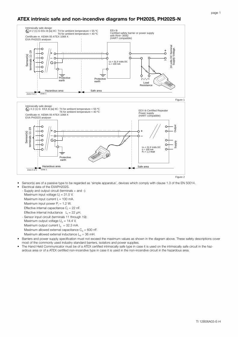
9EEx ibCertified safety barrier or power supplywith Rint= 300Ω(HART compatible)
Intrinsically safe designII 2 (1) G EEx ib [ia] IIC: T4 for ambient temperature < 55 ºC
T6 for ambient temperature < 40 ºCCertificate nr. KEMA 00 ATEX 1068 XEXA PH202S analyser
Uo = 31.5 Volts DCIo = 100 mAPo = 1.2 Watt
EEX ib Certified RepeaterPower supply(HART compatible)
Intrinsically safe design II 2 (1) G EEX ib [ia] IIC: T4 for ambient temperature < 55 ºC
T6 for ambient temperature < 40 ºCCertificate nr. KEMA 00 ATEX 1068 XEXA PH202S analyser
Zone 0 or 1 Zone 1
Zone 0 or 1 Zone 1
Sen
sor(
s)te
rmin
als
11-1
9
Figure 1
Figure 2
• Sensor(s) are of a passive type to be regarded as ‘simple apparatus’, devices which comply with clause 1.3 of the EN 50014.• Electrical data of the EXAPH202S.
- Supply and output circuit (terminals + and -):Maximum input voltage Ui = 31.5 V.Maximum input current Ii = 100 mA.Maximum input power Pi = 1.2 W.Effective internal capacitance Ci = 22 nF.Effective internal inductance Li = 22 µH.
- Sensor input circuit (terminals 11 through 19):Maximum output voltage Uo = 14.4 V.Maximum output current Io = 32.3 mA.Maximum allowed external capacitance Co = 600 nF.Maximum allowed external inductance Lo = 36 mH.
• Barriers and power supply specification must not exceed the maximum values as shown in the diagram above. These safety descriptions covermost of the commonly used industry standard barriers, isolators and power supplies.
• The Hand Held Communicator must be of a ATEX certified intrinsically safe type in case it is used on the intrinsically safe circuit in the haz-ardous area or of a ATEX certified non-incendive type in case it is used in the non-incendive circuit in the hazardous area.
ATEX intrinsic safe and non-incendive diagrams for PH202S, PH202S-N
page 2
TI 12B06A03-E-H
Safe area
Out
put
Sup
ply
+_
G
Hazardous area Safe area
+_
G
Protectiveearth
Protectiveearth
+
_
LoadResistance
Hazardous area
Protective earth
+_
24 v
olts
DC
Nom
inal
Sup
ply
Vol
tage
.
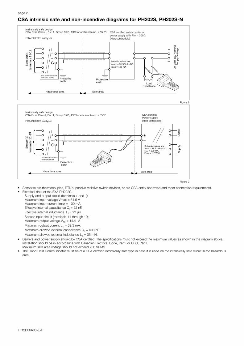
CSA certified safety barrier orpower supply with Rint = 300Ω(Hart compatible)
Intrinsically safe designCSA Ex ia Class I, Div. 1, Group C&D, T3C for ambient temp. < 55 ºC
EXA PH202S analyser
CSA certifiedPower supply(Hart compatible)
For electrical data:see text below
For electrical data:see text below
Suitable values are:Vmax = 31.5 Volts DCImax = 100 mA
Suitable values are:Vmax = 31.5 Volts DCImax = 100 mAPmax = 1.2 Watt
Intrinsically safe designCSA Ex ia Class I, Div. 1, Group C&D, T3C for ambient temp. < 55 ºC
EXA PH202S analyser
Sen
sor(
s)te
rmin
als
11-1
9S
enso
r(s)
term
inal
s 11
-19
Figure 1
Figure 2
• Sensor(s) are thermocouples, RTD’s, passive resistive switch devices, or are CSA entity approved and meet connection requirements.• Electrical data of the EXA PH202S.
- Supply and output circuit (terminals + and -): Maximum input voltage Vmax = 31.5 V.Maximum input current Imax = 100 mA.Effective internal capacitance Ci = 22 nF.Effective internal inductance Li = 22 µH.
- Sensor input circuit (terminals 11 through 19):Maximum output voltage Voc = 14.4 V.Maximum output current Isc = 32.3 mA.Maximum allowed external capacitance Ca = 600 nF.Maximum allowed external inductance La = 36 mH.
• Barriers and power supply should be CSA certified. The specifications must not exceed the maximum values as shown in the diagram above.Installation should be in accordance with Canadian Electrical Code, Part I or CEC, Part I.Maximum safe area voltage should not exceed 250 VRMS.
• The Hand Held Communicator must be of a CSA certified intrinsically safe type in case it is used on the intrinsically safe circuit in the hazardousarea.
CSA intrinsic safe and non-incendive diagrams for PH202S, PH202S-N
page 3
TI 12B06A03-E-H
Safe area
Out
put
Sup
ply
+_
G
Hazardous area
Protective earth
+_
FM ApprovedPower supply(HART compatible)
Intrinsically safe designFM Class I. Div. 1, Group ABCD, T3B for ambient temperature < 55 ºC
T4 for ambient temperature < 40 ºCEXA PH202S analyser
see text belowFor electrical data:
Hazardous area Safe area
+_
G
Protectiveearth
Protectiveearth
+
_
LoadResistance
24 v
olts
DC
Nom
inal
Sup
ply
Vol
tage
.
Intrinsically safe designFM Class I. Div. 1, Group ABCD: T3B for ambient temperature < 55 ºC
T4 for ambient temperature < 40 ºCEXA PH202S analyser
For electrical data:see text below
FM ApprovedSafety barrier or power supplywith Rint = 300Ω(HART compatible)
Sen
sor(
s)te
rmin
als
11-1
9M
ax. c
able
leng
ht: 6
0 m
tr.
Cab
le d
iam
.: 3
to 1
2 m
m.
Sen
sor(
s)te
rmin
als
11-1
9M
ax. c
able
leng
ht: 6
0 m
tr.
Cab
le d
iam
.: 3
to 1
2 m
m.
Figure 1
Figure 2
Suitable values are:Voc or Vt ≤ 31.5 Volt DClsc or lt ≤ 100 mAPsc or Pt ≤ 1.2 Watt
Suitable values are:Voc or Vt ≤ 31.5 Volt DCIsc or It ≤ 100 mA
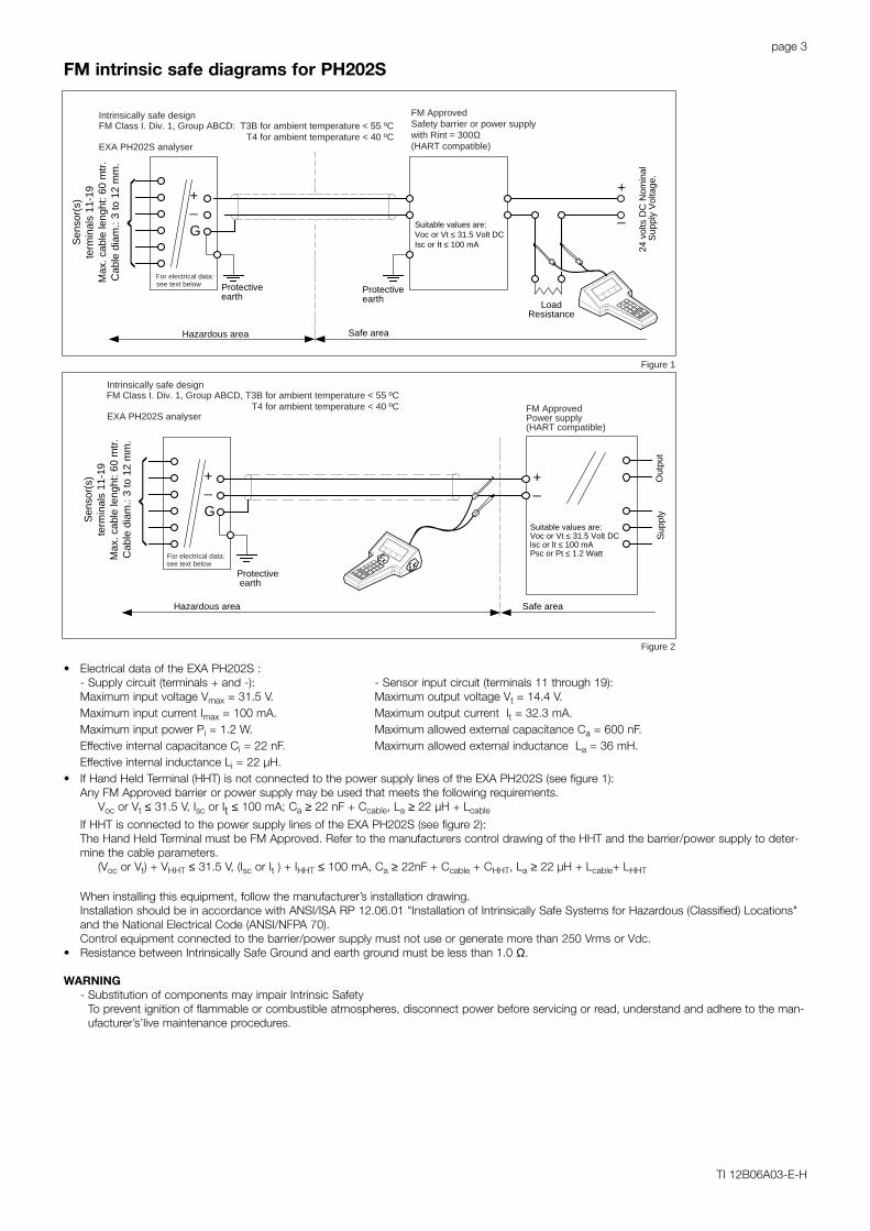
• Electrical data of the EXA PH202S :- Supply circuit (terminals + and -): - Sensor input circuit (terminals 11 through 19):Maximum input voltage Vmax = 31.5 V. Maximum output voltage Vt = 14.4 V.Maximum input current Imax = 100 mA. Maximum output current It = 32.3 mA.Maximum input power Pi = 1.2 W. Maximum allowed external capacitance Ca = 600 nF.Effective internal capacitance Ci = 22 nF. Maximum allowed external inductance La = 36 mH.Effective internal inductance Li = 22 µH.
• If Hand Held Terminal (HHT) is not connected to the power supply lines of the EXA PH202S (see figure 1):Any FM Approved barrier or power supply may be used that meets the following requirements.
Voc or Vt ≤ 31.5 V, Isc or It ≤ 100 mA; Ca ≥ 22 nF + Ccable, La ≥ 22 µH + Lcable
If HHT is connected to the power supply lines of the EXA PH202S (see figure 2):The Hand Held Terminal must be FM Approved. Refer to the manufacturers control drawing of the HHT and the barrier/power supply to deter-mine the cable parameters.
(Voc or Vt) + VHHT ≤ 31.5 V, (Isc or It ) + IHHT ≤ 100 mA, Ca ≥ 22nF + Ccable + CHHT, La ≥ 22 µH + Lcable+ LHHT
When installing this equipment, follow the manufacturer’s installation drawing.Installation should be in accordance with ANSI/ISA RP 12.06.01 "Installation of Intrinsically Safe Systems for Hazardous (Classified) Locations"and the National Electrical Code (ANSI/NFPA 70).Control equipment connected to the barrier/power supply must not use or generate more than 250 Vrms or Vdc.
• Resistance between Intrinsically Safe Ground and earth ground must be less than 1.0 Ω.
WARNING- Substitution of components may impair Intrinsic Safety
To prevent ignition of flammable or combustible atmospheres, disconnect power before servicing or read, understand and adhere to the man-ufacturer’s’live maintenance procedures.
FM intrinsic safe diagrams for PH202S
page 4
TI 12B06A03-E-H
Unclassified location
+_
G
Classified location
Protective earth
Intrinsically safe designFM Class I. Div. 2, Group ABCD, T3B for ambient temperature < 55 ºC
T4 for ambient temperature < 40 ºCEXA PH202S analyser
see text belowFor electrical data:
Classified location Unclassified location
+_
G
Protectiveearth
+
_
LoadResistance
FM
App
rove
dpo
wer
sup
ply
VO
C ≤
31.
5 V
DC
Intrinsically safe designFM Class I. Div. 2, Group ABCD: T3B for ambient temperature < 55 ºC
T4 for ambient temperature < 40 ºCEXA PH202S analyser
For electrical data:see text below
Sen
sor(
s)te
rmin
als
11-1
9M
ax. c
able
leng
th: 6
0 m
tr.
Cab
le d
iam
.: 3
to 1
2 m
m.
Sen
sor(
s)te
rmin
als
11-1
9M
ax. c
able
leng
th: 6
0 m
tr.
Cab
le d
iam
.: 3
to 1
2 m
m.
+
_
FM
App
rove
dpo
wer
sup
ply
VO
C ≤
31.
5 V
DC
Figure 1
Figure 2
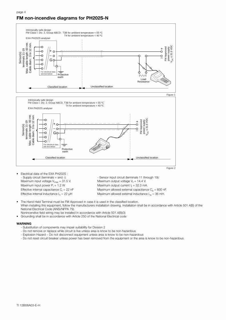
• Electrical data of the EXA PH202S :- Supply circuit (terminals + and -): - Sensor input circuit (terminals 11 through 19):Maximum input voltage Vmax = 31.5 V. Maximum output voltage Vt = 14.4 V.Maximum input power Pi = 1.2 W Maximum output current It = 32.3 mA.Effective internal capacitance Ci = 22 nF Maximum allowed external capacitance Ca = 600 nF.Effective internal inductance Li = 22 µH Maximum allowed external inductance La = 36 mH.
• The Hand Held Terminal must be FM Approved in case it is used in the classified location.When installing this equipment, follow the manufacturers installation drawing. Installation shall be in accordance with Article 501.4(B) of theNational Electrical Code (ANSI/NFPA 79).Nonincendive field wiring may be installed in accordance with Article 501.4(B)(3)
• Grounding shall be in accordance with Article 250 of the National Electrical code
WARNING- Substitution of components may impair suitability for Division 2- Do not remove or replace while circuit is live unless area is know to be non-hazardous- Explosion Hazard – Do not disconnect equipment unless area is know to be non-hazardous- Do not reset circuit breaker unless power has been removed from the equipment or the area is know to be non-hazardous
FM non-incendive diagrams for PH202S-N
page 5
TI 12B06A03-E-H
SensorConnections
EEx ib[ia] IIC, Certificate no. 00ATEX 1068 XT4 for ambient temperature ≤ 55 ºCT6 for ambient temperature ≤ 40 ºC
Ui = 24 VoltIi = 250 mA
Pi = 1.2 Watt
or Ui = 17.5 VoltIi = 380 mA
Pi = 5.32 Watt
I.S. CertifiedTerminator
EXAPH202S-F
Safe areaApparatus
I.S.Interface
Safe area
Zone 1 Zone 0 or 1
Hazardous area
ATEX
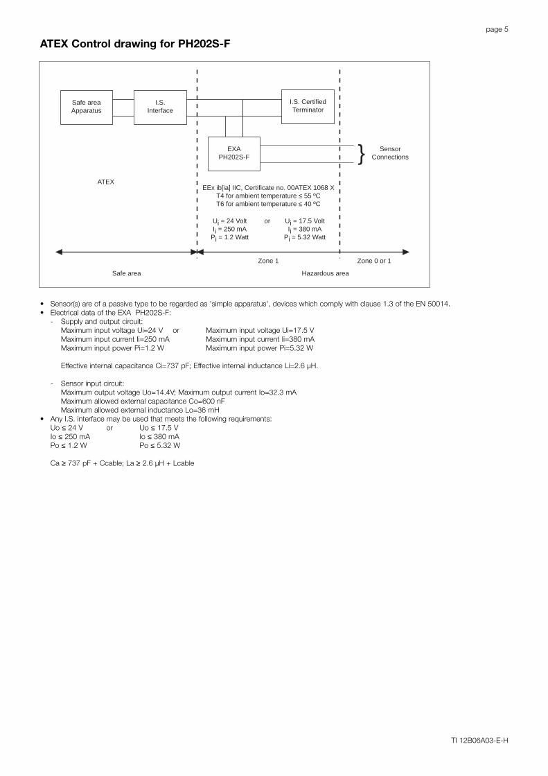
• Sensor(s) are of a passive type to be regarded as 'simple apparatus', devices which comply with clause 1.3 of the EN 50014.• Electrical data of the EXA PH202S-F:
- Supply and output circuit:Maximum input voltage Ui=24 V or Maximum input voltage Ui=17.5 VMaximum input current Ii=250 mA Maximum input current Ii=380 mAMaximum input power Pi=1.2 W Maximum input power Pi=5.32 W
Effective internal capacitance Ci=737 pF; Effective internal inductance Li=2.6 µH.
- Sensor input circuit:Maximum output voltage Uo=14.4V; Maximum output current Io=32.3 mAMaximum allowed external capacitance Co=600 nFMaximum allowed external inductance Lo=36 mH
• Any I.S. interface may be used that meets the following requirements:Uo ≤ 24 V or Uo ≤ 17.5 VIo ≤ 250 mA Io ≤ 380 mAPo ≤ 1.2 W Po ≤ 5.32 W
Ca ≥ 737 pF + Ccable; La ≥ 2.6 µH + Lcable
ATEX Control drawing for PH202S-F
page 6
TI 12B06A03-E-H
SensorConnections
CSA Ex ia Class I, DIV. 1, Group C&DT3C for ambient temperature ≤ 55 ºC
Vmax = 24 VoltImax = 250 mA
Pmax = 1.2 Watt
or Vmax = 17.5 VoltImax = 380 mA
Pmax = 5.32 Watt
I.S. CertifiedTerminator
EXAPH202S-F
Safe areaApparatus
I.S.Interface
Safe area
Zone 1 Zone 0 or 1
Hazardous area
CSA
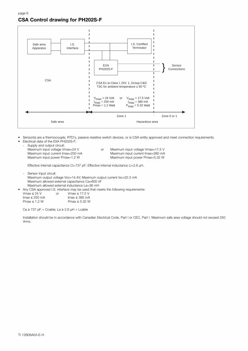
• Sensor(s) are a thermocouple, RTD's, passive resistive switch devices, or is CSA entity approved and meet connection requirements.• Electrical data of the EXA PH202S-F:
- Supply and output circuit:Maximum input voltage Vmax=24 V or Maximum input voltage Vmax=17.5 VMaximum input current Imax=250 mA Maximum input current Imax=380 mAMaximum input power Pmax=1.2 W Maximum input power Pmax=5.32 W
Effective internal capacitance Ci=737 pF; Effective internal inductance Li=2.6 µH.
- Sensor input circuit:Maximum output voltage Voc=14.4V; Maximum output current Isc=32.3 mAMaximum allowed external capacitance Ca=600 nFMaximum allowed external inductance La=36 mH
• Any CSA approved I.S. interface may be used that meets the following requirements:Vmax ≤ 24 V or Vmax ≤ 17.5 VImax ≤ 250 mA Imax ≤ 380 mAPmax ≤ 1.2 W Pmax ≤ 5.32 W
Ca ≥ 737 pF + Ccable; La ≥ 2.6 µH + Lcable
Installation should be in accordance with Canadian Electrical Code, Part I or CEC, Part I. Maximum safe area voltage should not exceed 250Vrms.
CSA Control drawing for PH202S-F

page 7
TI 12B06A03-E-H
SensorConnectionsMax. cablelength: 60 mtr.Cable diameter: 3 to 12 mm.
FM Class I, DIV. 1, Group ABCDT3B for ambient temperature ≤ 55 ºCT4 for ambient temperature ≤ 40 ºC
FM ApprovedTerminator
R = 90 to 100 ΩC = 0 to 2.2 µF
EXAPH202S-F
FM ApprovedFISCO barrier
Voc (Vt) ≤ 17.5 VIoc (It) ≤ 380 mAPoc (Pt) ≤ 5.32 W
Unclassified LocationDivision 1
Classified Location
FMI.S. FISCO
• Sensor(s) are of a passive type to be regarded as 'simple apparatus', devices which neither store nor generate voltages over 1.5 V, currentsover 0.1 A, power over 25 mW or energy over 20 µJ, or are FM Approvals entity approved and meet connection requirements.
• Electrical data of the EXA PH202S-F:- Supply circuit: Vmax=17,5 V; Imax=380 mA; Pi=5,32 W; Ci=737 pF; Li=2.6 µH.- Sensor input circuit: Vt=14.4 V; It=32.3 mA; Ca=600 nF; La=36 mH
• Any FM Approved FISCO barrier may be used that meets the following requirements:Voc or Vt ≤ 17,5 V; Ioc or It ≤ 380 mA; Poc or Pt ≤ 5,32 WWhen installing this equipment, follow the manufacturer’s installation drawing.Installation should be in accordance with ANSI/ISA RP 12.06.01 "Installation of Intrinsically Safe Systems for Hazardous (Classified) Locations"and the National Electrical Code (ANSI/NFPA 70).Associated apparatus connected to the FISCO barrier must not use or generate more than 250 Vrms or Vdc.
• Resistance between FISCO Intrinsically Safe Ground and earth ground must be less than 1.0 Ω.• The FISCO concept allows the interconnection of several I.S. apparatus not specifically examined in such combination. The criterion for such
interconnection is that the voltage (Vmax), the current (Imax) and the power (Pi) which I.S. apparatus can receive and remain intrinsically safe,considering faults, must be equal to or greater that the voltage (Voc, Vt), the current (Ioc, It) and the power (Poc, Pt) which can be providede bythe FM approved FISCO barrier. In addition, the maximum unprotected residual capacitance (Ci) and inductance (Li) of each apparatus (otherthan the terminator) connected to the Fieldbus must be less than or equal to 5nF and 10 µH respectively.
• In each I.S. Fieldbus segment only one active source, normally the FM Approved FISCO barrier, is allowed to provide the necessary power forthe Fieldbus system. All other equipment connected to the bus cable has to be passive (not providing energy to the system), except to a leak-age current of 50µA for each connected device. Seperately powered equipment needs a galvanic isolation to insure that the I.S. Fieldbus circuitremains passive.
• The cable used to interconnect the devices needs to comply with the following parameters:Loop resistance R’: 15 to 150 Ω/km; Inductance per unit length L’: 0.4 to 1 mH/kmCapacitance per unit length C’: 80 to 200 nF/km(C’ = C’ line/line + 0.5 C’ line/screen if both line are floating)(C’ = C’ line/line + C’ line/screen if the screen is connected to one line)Length of spur cable: max. 30 mtr.Length of trunk cable: max. 1 kmLength of splice : max. 1 mtr.
WARNING- Substitution of components may impair Intrinsic Safety- To prevent ignition of flammable or combustible atmospheres, disconnect power before servicing or read, understand and adhere to the
manufacturer’s’live maintenance procedures.
FM Control drawing for PH202S-F (Intrinsic safe FISCO concept)
page 8
TI 12B06A03-E-H
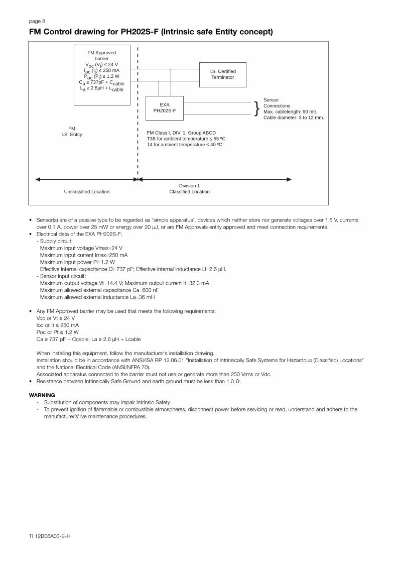
SensorConnectionsMax. cablelength: 60 mtr.Cable diameter: 3 to 12 mm.
FM Class I, DIV. 1, Group ABCDT3B for ambient temperature ≤ 55 ºCT4 for ambient temperature ≤ 40 ºC
I.S. CertifiedTerminator
EXAPH202S-F
FM Approvedbarrier
Voc (Vt) ≤ 24 VIoc (It) ≤ 250 mAPoc (Pt) ≤ 1.2 W
Ca ≥ 737pF + CcableLa ≥ 2.6µH + Lcable
Unclassified LocationDivision 1
Classified Location
FMI.S. Entity
• Sensor(s) are of a passive type to be regarded as 'simple apparatus', devices which neither store nor generate voltages over 1.5 V, currentsover 0.1 A, power over 25 mW or energy over 20 µJ, or are FM Approvals entity approved and meet connection requirements.
• Electrical data of the EXA PH202S-F:- Supply circuit:
Maximum input voltage Vmax=24 VMaximum input current Imax=250 mA Maximum input power Pi=1.2 WEffective internal capacitance Ci=737 pF; Effective internal inductance Li=2.6 µH.
- Sensor input circuit:Maximum output voltage Vt=14.4 V; Maximum output current It=32.3 mAMaximum allowed external capacitance Ca=600 nFMaximum allowed external inductance La=36 mH
• Any FM Approved barrier may be used that meets the following requirements:Voc or Vt ≤ 24 VIoc or It ≤ 250 mAPoc or Pt ≤ 1.2 WCa ≥ 737 pF + Ccable; La ≥ 2.6 µH + Lcable
When installing this equipment, follow the manufacturer’s installation drawing.Installation should be in accordance with ANSI/ISA RP 12.06.01 "Installation of Intrinsically Safe Systems for Hazardous (Classified) Locations"and the National Electrical Code (ANSI/NFPA 70). Associated apparatus connected to the barrier must not use or generate more than 250 Vrms or Vdc.
• Resistance between Intrinsically Safe Ground and earth ground must be less than 1.0 Ω.
WARNING- Substitution of components may impair Intrinsic Safety- To prevent ignition of flammable or combustible atmospheres, disconnect power before servicing or read, understand and adhere to the
manufacturer’s’live maintenance procedures.
FM Control drawing for PH202S-F (Intrinsic safe Entity concept)

page 9
TI 12B06A03-E-H
SensorConnectionsMax. cablelength: 60 mtr.Cable diameter: 3 to 12 mm.
FM Class I, DIV. 2, Group ABCDT3B for ambient temperature ≤ 55 ºCT4 for ambient temperature ≤ 40 ºC
FM Approvedterminator
R = 90 to 100 ΩC = 0 to 2.2 µF
EXAPH202S-B
FM ApprovedPower supplyVoc ≤ 32 VDC
Unclassified LocationDivision 2
Classified Location
FMN.I. FISCO
• Sensor(s) are of a passive type to be regarded as 'simple apparatus', devices which neither store nor generate voltages over 1.5 V, currentsover 0.1 A, power over 25 mW or energy over 20 µJ, or are FM Approvals entity approved and meet connection requirements.
• Electrical data of the EXA PH202S-B:- Supply circuit: Vmax=32 V; Pi=5.32 W; Ci= 737 pF; Li= 2.6 µH- Sensor input circuit: Vt=14.4 V; It=32.3 mA; Ca=600 nF; La=36 mHWhen installing this equipment, follow the manufacturers installation drawing.Installation shall be in accordance with Article 501.4(B) of the National Electrical Code (ANSI/NFPA 79). Nonincendive field wiring may beinstalled in accordance with Article 501.4(B)(3)
• Grounding shall be in accordance with Article 250 of the National Electrical code.
WARNING- Substitution of components may impair suitability for Division 2.- Do not remove or replace while circuit is live unless area is know to be non-hazardous- Explosion Hazard – Do not disconnect equipment unless area is know to be non-hazardous- Do not reset circuit breaker unless power has been removed from the equipment or the area is know to be non-hazardous
FM control drawing for PH202S-B (Non-incendive FISCO concept)
page 10
TI 12B06A03-E-H
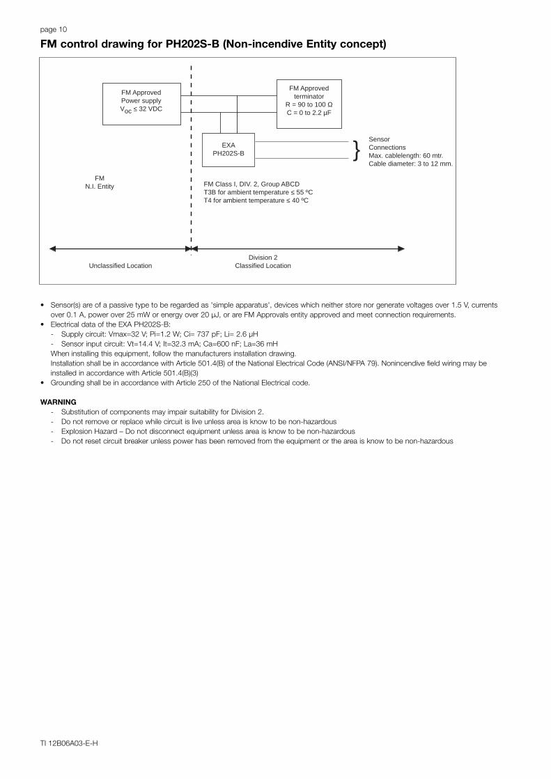
SensorConnectionsMax. cablelength: 60 mtr.Cable diameter: 3 to 12 mm.
FM Class I, DIV. 2, Group ABCDT3B for ambient temperature ≤ 55 ºCT4 for ambient temperature ≤ 40 ºC
FM Approvedterminator
R = 90 to 100 ΩC = 0 to 2.2 µF
EXAPH202S-B
FM ApprovedPower supplyVoc ≤ 32 VDC
Unclassified LocationDivision 2
Classified Location
FMN.I. Entity
• Sensor(s) are of a passive type to be regarded as 'simple apparatus', devices which neither store nor generate voltages over 1.5 V, currentsover 0.1 A, power over 25 mW or energy over 20 µJ, or are FM Approvals entity approved and meet connection requirements.
• Electrical data of the EXA PH202S-B:- Supply circuit: Vmax=32 V; Pi=1.2 W; Ci= 737 pF; Li= 2.6 µH- Sensor input circuit: Vt=14.4 V; It=32.3 mA; Ca=600 nF; La=36 mHWhen installing this equipment, follow the manufacturers installation drawing.Installation shall be in accordance with Article 501.4(B) of the National Electrical Code (ANSI/NFPA 79). Nonincendive field wiring may beinstalled in accordance with Article 501.4(B)(3)
• Grounding shall be in accordance with Article 250 of the National Electrical code.
WARNING- Substitution of components may impair suitability for Division 2.- Do not remove or replace while circuit is live unless area is know to be non-hazardous- Explosion Hazard – Do not disconnect equipment unless area is know to be non-hazardous- Do not reset circuit breaker unless power has been removed from the equipment or the area is know to be non-hazardous
FM control drawing for PH202S-B (Non-incendive Entity concept)
page 11
TI 12B06A03-E-H
Safe areaO
utpu
tS
uppl
y
SE
NS
OR
term
inal
11-
16
+_
G
Hazardous area Safe area
+_
G
Protectiveearth
Protectiveearth
+
_
LoadResistance
Uo = 31.5 Volts DCIo = 100 mA
Hazardous area
Protective earth
+_
24 v
olts
DC
Nom
inal
Sup
ply
Vol
tage
.
SE
NS
OR
term
inal
11-
16
EEX ibCertified safety barrier or power supplywith Rint= 300Ω(HART compatible)
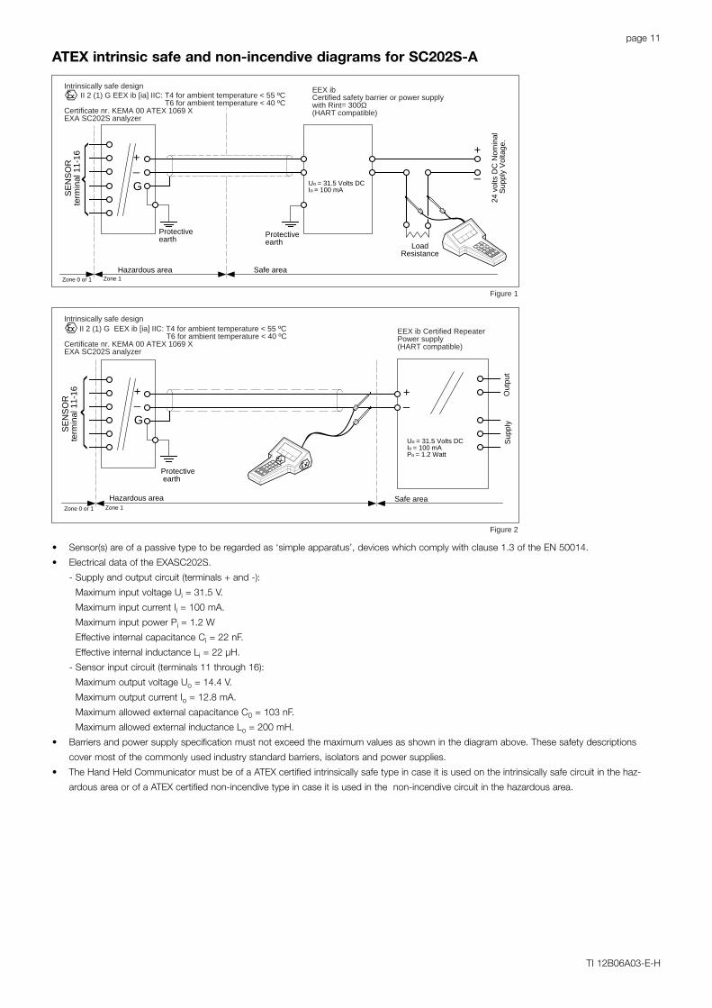
Intrinsically safe design II 2 (1) G EEX ib [ia] IIC: T4 for ambient temperature < 55 ºC
T6 for ambient temperature < 40 ºCCertificate nr. KEMA 00 ATEX 1069 XEXA SC202S analyzer
Uo = 31.5 Volts DCIo = 100 mAPo = 1.2 Watt
EEX ib Certified RepeaterPower supply(HART compatible)
Intrinsically safe design II 2 (1) G EEX ib [ia] IIC: T4 for ambient temperature < 55 ºC
T6 for ambient temperature < 40 ºCCertificate nr. KEMA 00 ATEX 1069 XEXA SC202S analyzer
Zone 0 or 1 Zone 1
Zone 0 or 1 Zone 1
Figure 1
Figure 2
• Sensor(s) are of a passive type to be regarded as ‘simple apparatus’, devices which comply with clause 1.3 of the EN 50014.
• Electrical data of the EXASC202S.
- Supply and output circuit (terminals + and -):
Maximum input voltage Ui = 31.5 V.
Maximum input current Ii = 100 mA.
Maximum input power Pi = 1.2 W
Effective internal capacitance Ci = 22 nF.
Effective internal inductance Li = 22 µH.
- Sensor input circuit (terminals 11 through 16):
Maximum output voltage Uo = 14.4 V.
Maximum output current Io = 12.8 mA.
Maximum allowed external capacitance C0 = 103 nF.
Maximum allowed external inductance Lo = 200 mH.
• Barriers and power supply specification must not exceed the maximum values as shown in the diagram above. These safety descriptions
cover most of the commonly used industry standard barriers, isolators and power supplies.
• The Hand Held Communicator must be of a ATEX certified intrinsically safe type in case it is used on the intrinsically safe circuit in the haz-
ardous area or of a ATEX certified non-incendive type in case it is used in the non-incendive circuit in the hazardous area.
ATEX intrinsic safe and non-incendive diagrams for SC202S-A
page 12
TI 12B06A03-E-H
Safe area
Out
put
Sup
ply
SE
NS
OR
(S)
term
inal
11-
16
+_
G
Hazardous area Safe area
+_
G
Protectiveearth
Protectiveearth
+
_
LoadResistance
Hazardous area
Protective earth
+_
24 v
olts
DC
Nom
inal
Sup
ply
Vol
tage
.
SE
NS
OR
(S)
term
inal
11-
16CSA certifiedSafety barrier or power supply(Hart compatible)
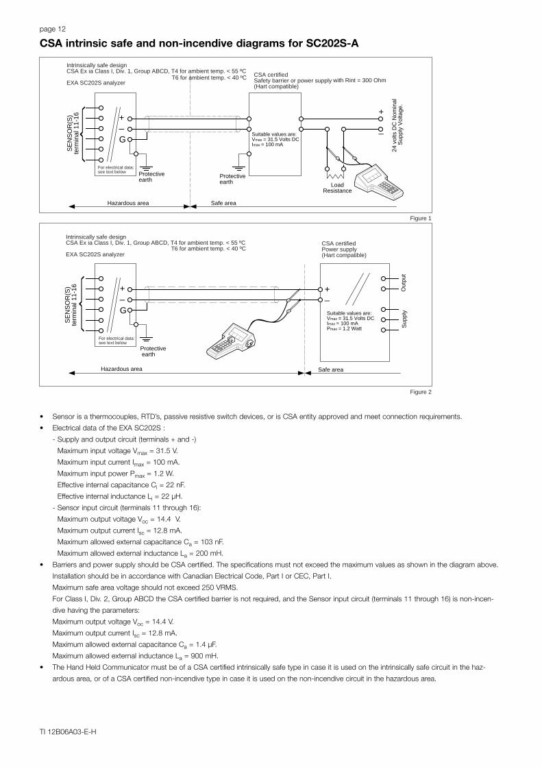
Intrinsically safe designCSA Ex ia Class I, Div. 1, Group ABCD, T4 for ambient temp. < 55 ºC
EXA SC202S analyzer T6 for ambient temp. < 40 ºC
CSA certifiedPower supply(Hart compatible)
For electrical data:see text below
For electrical data:see text below
Suitable values are:Vmax = 31.5 Volts DCImax = 100 mA
Suitable values are:Vmax = 31.5 Volts DCImax = 100 mAPmax = 1.2 Watt
Intrinsically safe designCSA Ex ia Class I, Div. 1, Group ABCD, T4 for ambient temp. < 55 ºC
EXA SC202S analyzer T6 for ambient temp. < 40 ºC
with Rint = 300 Ohm
Figure 1
Figure 2
• Sensor is a thermocouples, RTD’s, passive resistive switch devices, or is CSA entity approved and meet connection requirements.
• Electrical data of the EXA SC202S :
- Supply and output circuit (terminals + and -)
Maximum input voltage Vmax = 31.5 V.
Maximum input current Imax = 100 mA.
Maximum input power Pmax = 1.2 W.
Effective internal capacitance Ci = 22 nF.
Effective internal inductance Li = 22 µH.
- Sensor input circuit (terminals 11 through 16):
Maximum output voltage Voc = 14.4 V.
Maximum output current Isc = 12.8 mA.
Maximum allowed external capacitance Ca = 103 nF.
Maximum allowed external inductance La = 200 mH.
• Barriers and power supply should be CSA certified. The specifications must not exceed the maximum values as shown in the diagram above.
Installation should be in accordance with Canadian Electrical Code, Part I or CEC, Part I.
Maximum safe area voltage should not exceed 250 VRMS.
For Class I, Div. 2, Group ABCD the CSA certified barrier is not required, and the Sensor input circuit (terminals 11 through 16) is non-incen-
dive having the parameters:
Maximum output voltage Voc = 14.4 V.
Maximum output current Isc = 12.8 mA.
Maximum allowed external capacitance Ca = 1.4 µF.
Maximum allowed external inductance La = 900 mH.
• The Hand Held Communicator must be of a CSA certified intrinsically safe type in case it is used on the intrinsically safe circuit in the haz-
ardous area, or of a CSA certified non-incendive type in case it is used on the non-incendive circuit in the hazardous area.
CSA intrinsic safe and non-incendive diagrams for SC202S-A
page 13
TI 12B06A03-E-H
Unclassified Location
Out
put
Sup
ply
+_
G
Classified Location
Protective earth
+_
FM ApprovedPower supply(HART compatible)
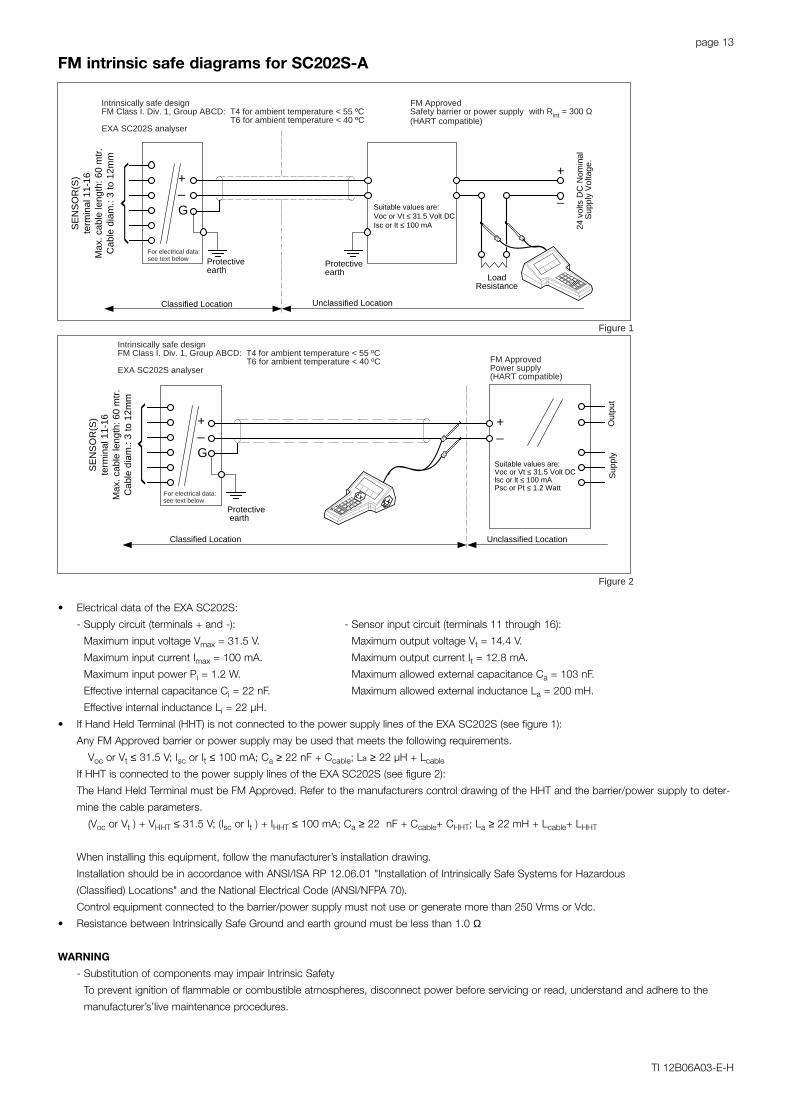
Intrinsically safe designFM Class I. Div. 1, Group ABCD: T4 for ambient temperature < 55 ºC
T6 for ambient temperature < 40 ºCEXA SC202S analyser
see text belowFor electrical data:
Classified Location Unclassified Location
+_
G
Protectiveearth
Protectiveearth
+
_
LoadResistance
24 v
olts
DC
Nom
inal
Sup
ply
Vol
tage
.
Safety barrier or power supply(HART compatible)
Intrinsically safe design FM ApprovedFM Class I. Div. 1, Group ABCD: T4 for ambient temperature < 55 ºC
T6 for ambient temperature < 40 ºCEXA SC202S analyser
with Rint = 300 Ω
For electrical data:see text below
SE
NS
OR
(S)
term
inal
11-
16M
ax. c
able
leng
th: 6
0 m
tr.
Cab
le d
iam
.: 3
to 1
2mm
SE
NS
OR
(S)
term
inal
11-
16M
ax. c
able
leng
th: 6
0 m
tr.
Cab
le d
iam
.: 3
to 1
2mm
Figure 1
Figure 2
Suitable values are:Voc or Vt ≤ 31.5 Volt DC
lsc or lt ≤ 100 mAPsc or Pt ≤ 1.2 Watt
Suitable values are:Voc or Vt ≤ 31.5 Volt DCIsc or It ≤ 100 mA
• Electrical data of the EXA SC202S:
- Supply circuit (terminals + and -): - Sensor input circuit (terminals 11 through 16):
Maximum input voltage Vmax = 31.5 V. - Maximum output voltage Vt = 14.4 V.
Maximum input current Imax = 100 mA. - Maximum output current It = 12.8 mA.
Maximum input power Pi = 1.2 W. - Maximum allowed external capacitance Ca = 103 nF.
Effective internal capacitance Ci = 22 nF. - Maximum allowed external inductance La = 200 mH.
Effective internal inductance Li = 22 µH.
• If Hand Held Terminal (HHT) is not connected to the power supply lines of the EXA SC202S (see figure 1):
Any FM Approved barrier or power supply may be used that meets the following requirements.
Voc or Vt ≤ 31.5 V; Isc or It ≤ 100 mA; Ca ≥ 22 nF + Ccable; La ≥ 22 µH + Lcable
If HHT is connected to the power supply lines of the EXA SC202S (see figure 2):
The Hand Held Terminal must be FM Approved. Refer to the manufacturers control drawing of the HHT and the barrier/power supply to deter-
mine the cable parameters.
(Voc or Vt ) + VHHT ≤ 31.5 V; (Isc or It ) + IHHT ≤ 100 mA; Ca ≥ 22 nF + Ccable+ CHHT; La ≥ 22 mH + Lcable+ LHHT
When installing this equipment, follow the manufacturer’s installation drawing.
Installation should be in accordance with ANSI/ISA RP 12.06.01 "Installation of Intrinsically Safe Systems for Hazardous
(Classified) Locations" and the National Electrical Code (ANSI/NFPA 70).
Control equipment connected to the barrier/power supply must not use or generate more than 250 Vrms or Vdc.
• Resistance between Intrinsically Safe Ground and earth ground must be less than 1.0 Ω
WARNING
- Substitution of components may impair Intrinsic Safety
To prevent ignition of flammable or combustible atmospheres, disconnect power before servicing or read, understand and adhere to the
manufacturer’s’live maintenance procedures.
FM intrinsic safe diagrams for SC202S-A
page 14
TI 12B06A03-E-H
Unclassified Location
+_
G
Classified Location
Protective earth
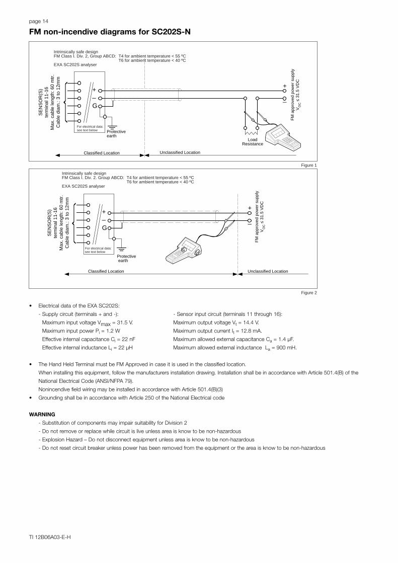
Intrinsically safe designFM Class I. Div. 2. Group ABCD: T4 for ambient temperature < 55 ºC
T6 for ambient temperature < 40 ºCEXA SC202S analyser
see text belowFor electrical data:
SE
NS
OR
(S)
term
inal
11-
16M
ax. c
able
leng
th: 6
0 m
tr.
Cab
le d
iam
.: 3
to 1
2mm
Classified Location Unclassified Location
+_
G
Protectiveearth
+
_
LoadResistance
FM
app
rove
d po
wer
sup
ply
VO
C ≤
31.
5 V
DC
Intrinsically safe designFM Class I. Div. 2, Group ABCD: T4 for ambient temperature < 55 ºC
T6 for ambient temperature < 40 ºCEXA SC202S analyser
For electrical data:see text below
SE
NS
OR
(S)
term
inal
11-
16M
ax. c
able
leng
th: 6
0 m
tr.
Cab
le d
iam
.: 3
to 1
2mm
FM
app
rove
d po
wer
sup
ply
VO
C ≤
31.
5 V
DC
+
_
Figure 2
Figure 1
• Electrical data of the EXA SC202S:
- Supply circuit (terminals + and -): - Sensor input circuit (terminals 11 through 16):
Maximum input voltage Vmax = 31.5 V. Maximum output voltage Vt = 14.4 V.
Maximum input power Pi = 1.2 W Maximum output current It = 12.8 mA.
Effective internal capacitance Ci = 22 nF Maximum allowed external capacitance Ca = 1.4 µF.
Effective internal inductance Li = 22 µH Maximum allowed external inductance La = 900 mH.
• The Hand Held Terminal must be FM Approved in case it is used in the classified location.
When installing this equipment, follow the manufacturers installation drawing. Installation shall be in accordance with Article 501.4(B) of the
National Electrical Code (ANSI/NFPA 79).
Nonincendive field wiring may be installed in accordance with Article 501.4(B)(3)
• Grounding shall be in accordance with Article 250 of the National Electrical code
WARNING
- Substitution of components may impair suitability for Division 2
- Do not remove or replace while circuit is live unless area is know to be non-hazardous
- Explosion Hazard – Do not disconnect equipment unless area is know to be non-hazardous
- Do not reset circuit breaker unless power has been removed from the equipment or the area is know to be non-hazardous
FM non-incendive diagrams for SC202S-N

page 15
TI 12B06A03-E-H
SensorConnections
EEx ib[ia] IIC, Certificate no. 00ATEX 1069 XT4 for ambient temperature ≤ 55 ºCT6 for ambient temperature ≤ 40 ºC
Ui = 24 VoltIi = 250 mA
Pi = 1.2 Watt
or Ui = 17.5 VoltIi = 380 mA
Pi = 5.32 Watt
I.S. CertifiedTerminator
EXASC202S-F
Safe areaApparatus
I.S.Interface
Safe area
Zone 1 Zone 0 or 1
Hazardous area
ATEX
• Sensor(s) are of a passive type to be regarded as 'simple apparatus', devices which comply with clause 1.3 of the EN 50014.• Electrical data of the EXA SC202S-F:
- Supply and output circuit:Maximum input voltage Ui=24 V or Maximum input voltage Ui=17.5 VMaximum input current Ii=250 mA Maximum input current Ii=380 mAMaximum input power Pi=1.2 W Maximum input power Pi=5.32 W
Effective internal capacitance Ci=737 pF; Effective internal inductance Li=2.6 µH.
- Sensor input circuit:Maximum output voltage Uo=14.4V; Maximum output current Io=12.8 mAMaximum allowed external capacitance Co=103 nFMaximum allowed external inductance Lo=200 mH
• Any I.S. interface may be used that meets the following requirements:Uo ≤ 24 V or Uo ≤ 17.5 VIo ≤ 250 mA Io ≤ 380mAPo ≤ 1.2 W Po ≤ 5.32 W
Ca ≥ 737 pF + Ccable; La ≥ 2.6 µH + Lcable
ATEX Control drawing for SC202S-F
page 16
TI 12B06A03-E-H
SensorConnections
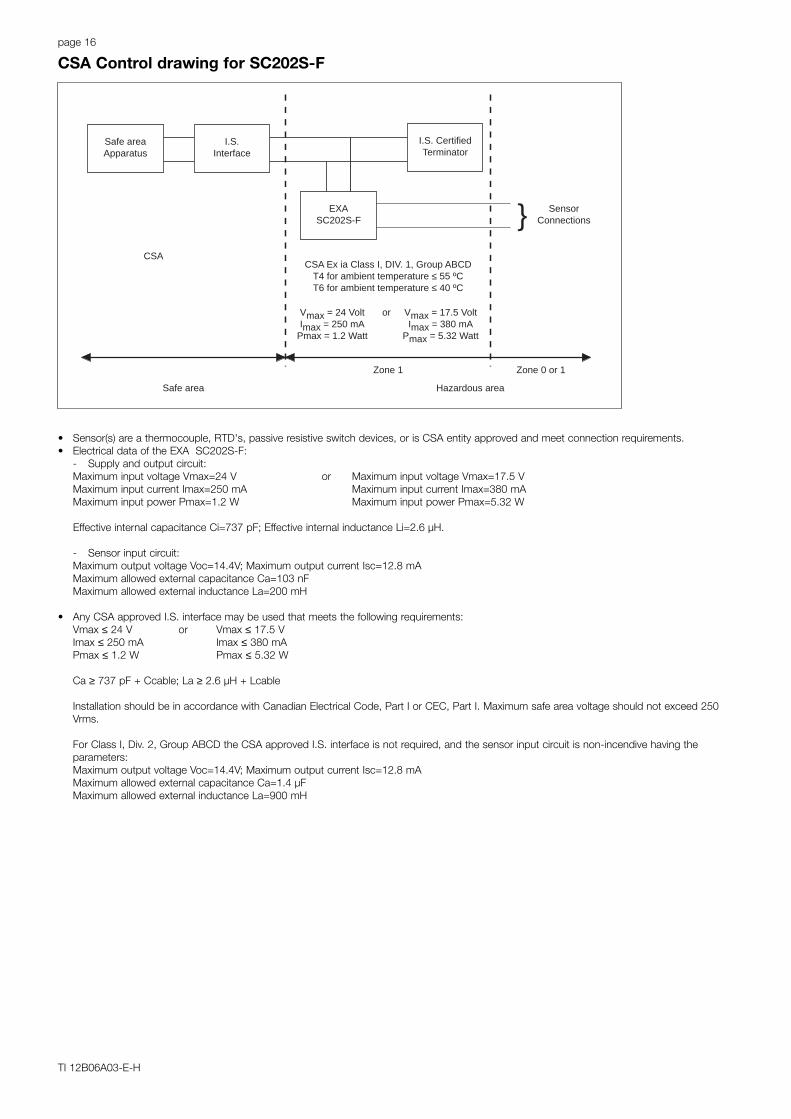
CSA Ex ia Class I, DIV. 1, Group ABCDT4 for ambient temperature ≤ 55 ºCT6 for ambient temperature ≤ 40 ºC
Vmax = 24 VoltImax = 250 mA
Pmax = 1.2 Watt
or Vmax = 17.5 VoltImax = 380 mA
Pmax = 5.32 Watt
I.S. CertifiedTerminator
EXASC202S-F
Safe areaApparatus
I.S.Interface
Safe area
Zone 1 Zone 0 or 1
Hazardous area
CSA
• Sensor(s) are a thermocouple, RTD's, passive resistive switch devices, or is CSA entity approved and meet connection requirements.• Electrical data of the EXA SC202S-F:
- Supply and output circuit:Maximum input voltage Vmax=24 V or Maximum input voltage Vmax=17.5 VMaximum input current Imax=250 mA Maximum input current Imax=380 mAMaximum input power Pmax=1.2 W Maximum input power Pmax=5.32 W
Effective internal capacitance Ci=737 pF; Effective internal inductance Li=2.6 µH.
- Sensor input circuit:Maximum output voltage Voc=14.4V; Maximum output current Isc=12.8 mAMaximum allowed external capacitance Ca=103 nFMaximum allowed external inductance La=200 mH
• Any CSA approved I.S. interface may be used that meets the following requirements:Vmax ≤ 24 V or Vmax ≤ 17.5 VImax ≤ 250 mA Imax ≤ 380 mAPmax ≤ 1.2 W Pmax ≤ 5.32 W
Ca ≥ 737 pF + Ccable; La ≥ 2.6 µH + Lcable
Installation should be in accordance with Canadian Electrical Code, Part I or CEC, Part I. Maximum safe area voltage should not exceed 250Vrms.
For Class I, Div. 2, Group ABCD the CSA approved I.S. interface is not required, and the sensor input circuit is non-incendive having theparameters:Maximum output voltage Voc=14.4V; Maximum output current Isc=12.8 mAMaximum allowed external capacitance Ca=1.4 µFMaximum allowed external inductance La=900 mH
CSA Control drawing for SC202S-F
page 17
TI 12B06A03-E-H
SensorConnectionsMax. cablelength: 60 mtr.Cable diameter: 3 to 12 mm.
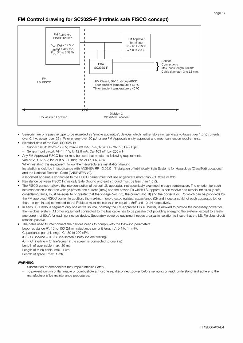
FM Class I, DIV. 1, Group ABCDT4 for ambient temperature ≤ 55 ºCT6 for ambient temperature ≤ 40 ºC
FM ApprovedTerminator
R = 90 to 100ΩC = 0 to 2.2 µF
EXASC202S-F
FM ApprovedFISCO barrier
Voc (Vt) ≤ 17.5 VIoc (It) ≤ 380 mAPoc (Pt) ≤ 5.32 W
Unclassified LocationDivision 1
Classified Location
FMI.S. FISCO
• Sensor(s) are of a passive type to be regarded as 'simple apparatus', devices which neither store nor generate voltages over 1.5 V, currentsover 0.1 A, power over 25 mW or energy over 20 µJ, or are FM Approvals entity approved and meet connection requirements.
• Electrical data of the EXA SC202S-F:- Supply circuit: Vmax=17,5 V; Imax=380 mA; Pi=5,32 W; Ci=737 pF; Li=2.6 µH.- Sensor input circuit: Vt=14.4 V; It=12.8 mA; Ca=103 nF; La=200 mH
• Any FM Approved FISCO barrier may be used that meets the following requirements:Voc or Vt ≤ 17,5 V; Ioc or It ≤ 380 mA; Poc or Pt ≤ 5,32 WWhen installing this equipment, follow the manufacturer’s installation drawing.Installation should be in accordance with ANSI/ISA RP 12.06.01 "Installation of Intrinsically Safe Systems for Hazardous (Classified) Locations"and the National Electrical Code (ANSI/NFPA 70).Associated apparatus connected to the FISCO barrier must not use or generate more than 250 Vrms or Vdc.
• Resistance between FISCO Intrinsically Safe Ground and earth ground must be less than 1.0 Ω.• The FISCO concept allows the interconnection of several I.S. apparatus not specifically examined in such combination. The criterion for such
interconnection is that the voltage (Vmax), the current (Imax) and the power (Pi) which I.S. apparatus can receive and remain intrinsically safe,considering faults, must be equal to or greater that the voltage (Voc, Vt), the current (Ioc, It) and the power (Poc, Pt) which can be providede bythe FM approved FISCO barrier. In addition, the maximum unprotected residual capacitance (Ci) and inductance (Li) of each apparatus (otherthan the terminator) connected to the Fieldbus must be less than or equal to 5nF and 10 µH respectively.
• In each I.S. Fieldbus segment only one active source, normally the FM Approved FISCO barrier, is allowed to provide the necessary power forthe Fieldbus system. All other equipment connected to the bus cable has to be passive (not providing energy to the system), except to a leak-age current of 50µA for each connected device. Seperately powered equipment needs a galvanic isolation to insure that the I.S. Fieldbus circuitremains passive.
• The cable used to interconnect the devices needs to comply with the following parameters:Loop resistance R’: 15 to 150 Ω/km; Inductance per unit length L’: 0,4 to 1 mH/kmCapacitance per unit length C’: 80 to 200 nF/km(C’ = C’ line/line + 0,5 C’ line/screen if both line are floating)(C’ = C’ line/line + C’ line/screen if the screen is connected to one line)Length of spur cable: max. 30 mtr.Length of trunk cable: max. 1 kmLength of splice : max. 1 mtr.
WARNING- Substitution of components may impair Intrinsic Safety- To prevent ignition of flammable or combustible atmospheres, disconnect power before servicing or read, understand and adhere to the
manufacturer’s’live maintenance procedures.
FM Control drawing for SC202S-F (Intrinsic safe FISCO concept)
page 18
TI 12B06A03-E-H
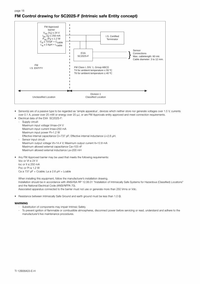
SensorConnectionsMax. cablelength: 60 mtr.Cable diameter: 3 to 12 mm.
FM Class I, DIV. 1, Group ABCDT4 for ambient temperature ≤ 55 ºCT6 for ambient temperature ≤ 40 ºC
I.S. CertifiedTerminator
EXASC202S-F
FM Approvedbarrier
Voc (Vt) ≤ 24 VIoc (It) ≤ 250 mAPoc (Pt) ≤ 1.2 W
Ca ≥ 737pF + CcableLa ≥ 2.6µH + Lcable
Unclassified LocationDivision 1
Classified Location
FMI.S. ENTITY
• Sensor(s) are of a passive type to be regarded as 'simple apparatus', devices which neither store nor generate voltages over 1.5 V, currentsover 0.1 A, power over 25 mW or energy over 20 µJ, or are FM Approvals entity approved and meet connection requirements.
• Electrical data of the EXA SC202S-F:- Supply circuit:
Maximum input voltage Vmax=24 VMaximum input current Imax=250 mAMaximum input power Pi=1.2 WEffective internal capacitance Ci=737 pF; Effective internal inductance Li=2.6 µH.
- Sensor input circuit:Maximum output voltage Vt=14.4 V; Maximum output current It=12.8 mAMaximum allowed external capacitance Ca=103 nFMaximum allowed external inductance La=200 mH
• Any FM Approved barrier may be used that meets the following requirements:Voc or Vt ≤ 24 VIoc or It ≤ 250 mAPoc or Pt ≤ 1.2 WCa ≥ 737 pF + Ccable; La ≥ 2.6 µH + Lcable
When installing this equipment, follow the manufacturer’s installation drawing.Installation should be in accordance with ANSI/ISA RP 12.06.01 "Installation of Intrinsically Safe Systems for Hazardous (Classified) Locations"and the National Electrical Code (ANSI/NFPA 70).Associated apparatus connected to the barrier must not use or generate more than 250 Vrms or Vdc.
• Resistance between Intrinsically Safe Ground and earth ground must be less than 1.0 Ω.
WARNING- Substitution of components may impair Intrinsic Safety- To prevent ignition of flammable or combustible atmospheres, disconnect power before servicing or read, understand and adhere to the
manufacturer’s’live maintenance procedures.
FM Control drawing for SC202S-F (Intrinsic safe Entity concept)
page 19
TI 12B06A03-E-H
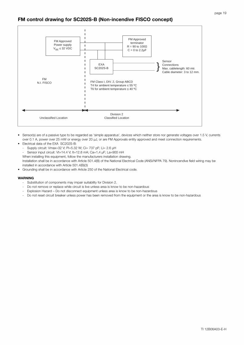
SensorConnectionsMax. cablelength: 60 mtr.Cable diameter: 3 to 12 mm.
FM Class I, DIV. 2, Group ABCDT4 for ambient temperature ≤ 55 ºCT6 for ambient temperature ≤ 40 ºC
FM Approvedterminator
R = 90 to 100ΩC = 0 to 2.2µF
EXASC202S-B
FM ApprovedPower supplyVoc ≤ 32 VDC
Unclassified LocationDivision 2
Classified Location
FMN.I. FISCO
• Sensor(s) are of a passive type to be regarded as 'simple apparatus', devices which neither store nor generate voltages over 1.5 V, currentsover 0.1 A, power over 25 mW or energy over 20 µJ, or are FM Approvals entity approved and meet connection requirements.
• Electrical data of the EXA SC202S-B:- Supply circuit: Vmax=32 V; Pi=5.32 W; Ci= 737 pF; Li= 2.6 µH- Sensor input circuit: Vt=14.4 V; It=12.8 mA; Ca=1,4 µF; La=900 mHWhen installing this equipment, follow the manufacturers installation drawing.Installation shall be in accordance with Article 501.4(B) of the National Electrical Code (ANSI/NFPA 79). Nonincendive field wiring may beinstalled in accordance with Article 501.4(B)(3)
• Grounding shall be in accordance with Article 250 of the National Electrical code.
WARNING- Substitution of components may impair suitability for Division 2.- Do not remove or replace while circuit is live unless area is know to be non-hazardous- Explosion Hazard – Do not disconnect equipment unless area is know to be non-hazardous- Do not reset circuit breaker unless power has been removed from the equipment or the area is know to be non-hazardous
FM control drawing for SC202S-B (Non-incendive FISCO concept)

page 20
TI 12B06A03-E-H
SensorConnectionsMax. cablelength: 60 mtr.Cable diameter: 3 to 12 mm.
FM Class I, DIV. 2, Group ABCDT4 for ambient temperature ≤ 55 ºCT6 for ambient temperature ≤ 40 ºC
FM Approvedterminator
R = 90 to 100ΩC = 0 to 2.2µF
EXASC202S-B
FM ApprovedPower supplyVoc ≤ 32 VDC
Unclassified LocationDivision 2
Classified Location
FMN.I. ENTITY
• Sensor(s) are of a passive type to be regarded as 'simple apparatus', devices which neither store nor generate voltages over 1.5 V, currentsover 0.1 A, power over 25 mW or energy over 20 µJ, or are FM Approvals entity approved and meet connection requirements.
• Electrical data of the EXA SC202S-B:- Supply circuit: Vmax=32 V; Pi=1.2 W; Ci= 737 pF; Li= 2.6 µH- Sensor input circuit: Vt=14.4 V; It=12.8 mA; Ca=1.4 µF; La=900 mHWhen installing this equipment, follow the manufacturers installation drawing.Installation shall be in accordance with Article 501.4(B) of the National Electrical Code (ANSI/NFPA 79). Nonincendive field wiring may beinstalled in accordance with Article 501.4(B)(3)
• Grounding shall be in accordance with Article 250 of the National Electrical code.
WARNING- Substitution of components may impair suitability for Division 2.- Do not remove or replace while circuit is live unless area is know to be non-hazardous- Explosion Hazard – Do not disconnect equipment unless area is know to be non-hazardous- Do not reset circuit breaker unless power has been removed from the equipment or the area is know to be non-hazardous
FM control drawing for SC202S-B (Non-incendive Entity concept)
page 21
TI 12B06A03-E-H
Safe area
Out
put
Sup
ply
+_
G
Hazardous area Safe area
+_
G
Protectiveearth
Protectiveearth
+
_
LoadResistance
Uo = 31.5 Volts DCIo = 100 mA
Hazardous area
Protective earth
+_
24 v
olts
DC
Nom
inal
Sup
ply
Vol
tage
.
ISC
40S
SE
NS
OR
term
inal
s 11
-17
ISC
40S
SE
NS
OR
term
inal
s 11
-17
EEx ibCertified safety barrier or power supplywith Rint= 300Ω(HART compatible)
Intrinsically safe designII 2 (1) G EEx ib [ia] IIC: T4 for ambient temperature < 55 ºC
T6 for ambient temperature < 40 ºCCertificate nr. KEMA 01 ATEX 1191 XEXA ISC202S analyser
Uo = 31.5 Volts DCIo = 100 mAPo = 1.2 Watt
EEX ib Certified RepeaterPower supply(HART compatible)
Intrinsically safe design II 2 (1) G EEX ib [ia] IIC: T4 for ambient temperature < 55 ºC
T6 for ambient temperature < 40 ºCCertificate nr. KEMA 01 ATEX 1191 XEXA ISC202S analyser
Zone 0 or 1 Zone 1
Zone 0 or 1 Zone 1
Figure 1
Figure 2
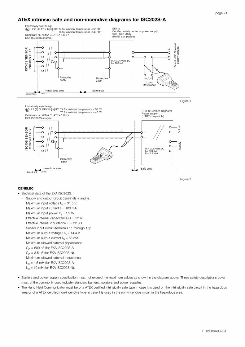
CENELEC
• Electrical data of the EXA ISC202S.
- Supply and output circuit (terminals + and -):
Maximum input voltage Ui = 31.5 V.
Maximum input current Ii = 100 mA.
Maximum input power Pi = 1.2 W
Effective internal capacitance Ci = 22 nF.
Effective internal inductance Li = 22 µH.
Sensor input circuit (terminals 11 through 17):
Maximum output voltage Uo = 14.4 V.
Maximum output current Io = 88 mA.
Maximum allowed external capacitance
Co = 600 nF (for EXA ISC202S-A),
Co = 3.5 µF (for EXA ISC202S-N).
Maximum allowed external inductance
Lo = 4.5 mH (for EXA ISC202S-A),
Lo = 10 mH (for EXA ISC202S-N),
• Barriers and power supply specification must not exceed the maximum values as shown in the diagram above. These safety descriptions cover
most of the commonly used industry standard barriers, isolators and power supplies.
• The Hand Held Communicator must be of a ATEX certified intrinsically safe type in case it is used on the intrinsically safe circuit in the hazardous
area or of a ATEX certified non-incendive type in case it is used in the non-incendive circuit in the hazardous area.
ATEX intrinsic safe and non-incendive diagrams for ISC202S-A
page 22
TI 12B06A03-E-H
Safe area
Out
put
Sup
ply
+_
G
Hazardous area Safe area
+_
G
Protectiveearth
Protectiveearth
+
_
LoadResistance
Hazardous area
Protective earth
+_
24 v
olts
DC
Nom
inal
Sup
ply
Vol
tage
.
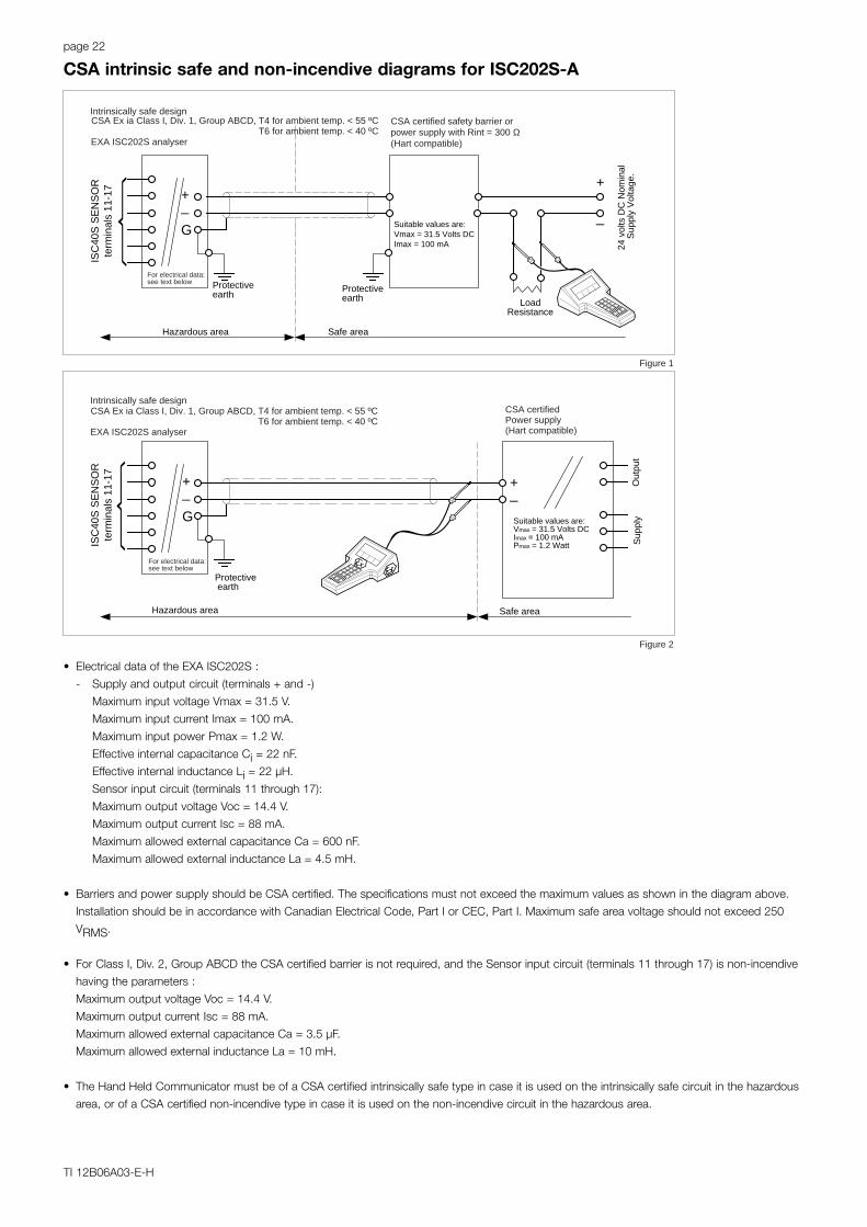
CSA certified safety barrier orpower supply with Rint = 300 Ω(Hart compatible)
Intrinsically safe designCSA Ex ia Class I, Div. 1, Group ABCD, T4 for ambient temp. < 55 ºC
T6 for ambient temp. < 40 ºCEXA ISC202S analyser
CSA certifiedPower supply(Hart compatible)
For electrical data:see text below
For electrical data:see text below
Suitable values are:Vmax = 31.5 Volts DCImax = 100 mA
Suitable values are:Vmax = 31.5 Volts DCImax = 100 mAPmax = 1.2 Watt
Intrinsically safe designCSA Ex ia Class I, Div. 1, Group ABCD, T4 for ambient temp. < 55 ºC
T6 for ambient temp. < 40 ºCEXA ISC202S analyser
ISC
40S
SE
NS
OR
term
inal
s 11
-17
ISC
40S
SE
NS
OR
term
inal
s 11
-17
Figure 1
Figure 2
• Electrical data of the EXA ISC202S :
- Supply and output circuit (terminals + and -)
Maximum input voltage Vmax = 31.5 V.
Maximum input current Imax = 100 mA.
Maximum input power Pmax = 1.2 W.
Effective internal capacitance Ci = 22 nF.
Effective internal inductance Li = 22 µH.
Sensor input circuit (terminals 11 through 17):
Maximum output voltage Voc = 14.4 V.
Maximum output current Isc = 88 mA.
Maximum allowed external capacitance Ca = 600 nF.
Maximum allowed external inductance La = 4.5 mH.
• Barriers and power supply should be CSA certified. The specifications must not exceed the maximum values as shown in the diagram above.
Installation should be in accordance with Canadian Electrical Code, Part I or CEC, Part I. Maximum safe area voltage should not exceed 250
VRMS.
• For Class I, Div. 2, Group ABCD the CSA certified barrier is not required, and the Sensor input circuit (terminals 11 through 17) is non-incendive
having the parameters :
Maximum output voltage Voc = 14.4 V.
Maximum output current Isc = 88 mA.
Maximum allowed external capacitance Ca = 3.5 µF.
Maximum allowed external inductance La = 10 mH.
• The Hand Held Communicator must be of a CSA certified intrinsically safe type in case it is used on the intrinsically safe circuit in the hazardous
area, or of a CSA certified non-incendive type in case it is used on the non-incendive circuit in the hazardous area.
CSA intrinsic safe and non-incendive diagrams for ISC202S-A
page 23
TI 12B06A03-E-H
Safe area
Out
put
Sup
ply
+_
G
Hazardous area
Protective earth
+_
Suitable values are:Voc or Vt ≤ 31.5 Volt DC
lsc or lt ≤ 100 mA
FM ApprovedPower supply(HART compatible)
Intrinsically safe designFM Class I. Div. 1, Group ABCD, T4 for ambient temperature < 55 ºC
T6 for ambient temperature < 40 ºCEXA ISC202S analyser
Psc or Pt ≤ 1.2 Watt
see text belowFor electrical data:
Hazardous area Safe area
+_
G
Protectiveearth
Protectiveearth
+
_
LoadResistance
Suitable values are:Voc or Vt ≤ 31.5 Volt DCIsc or It ≤ 100 mA 24
vol
ts D
C N
omin
al S
uppl
y V
olta
ge.
Intrinsically safe designFM Class I. Div. 1, Group ABCD: T4 for ambient temperature < 55 ºC
T6 for ambient temperature < 40 ºCEXA ISC202S analyser
For electrical data:see text below
FM ApprovedSafety barrier or power supplywith Rint = 300 Ω(HART compatible)
ISC
40S
SE
NS
OR
term
inal
s 11
-17
Max
. cab
le le
nght
: 60
mtr
.C
able
dia
m.:
3 to
12
mm
.
ISC
40S
SE
NS
OR
term
inal
s 11
-17
Max
. cab
le le
nght
: 60
mtr
.C
able
dia
m.:
3 to
12
mm
.
Figure 1
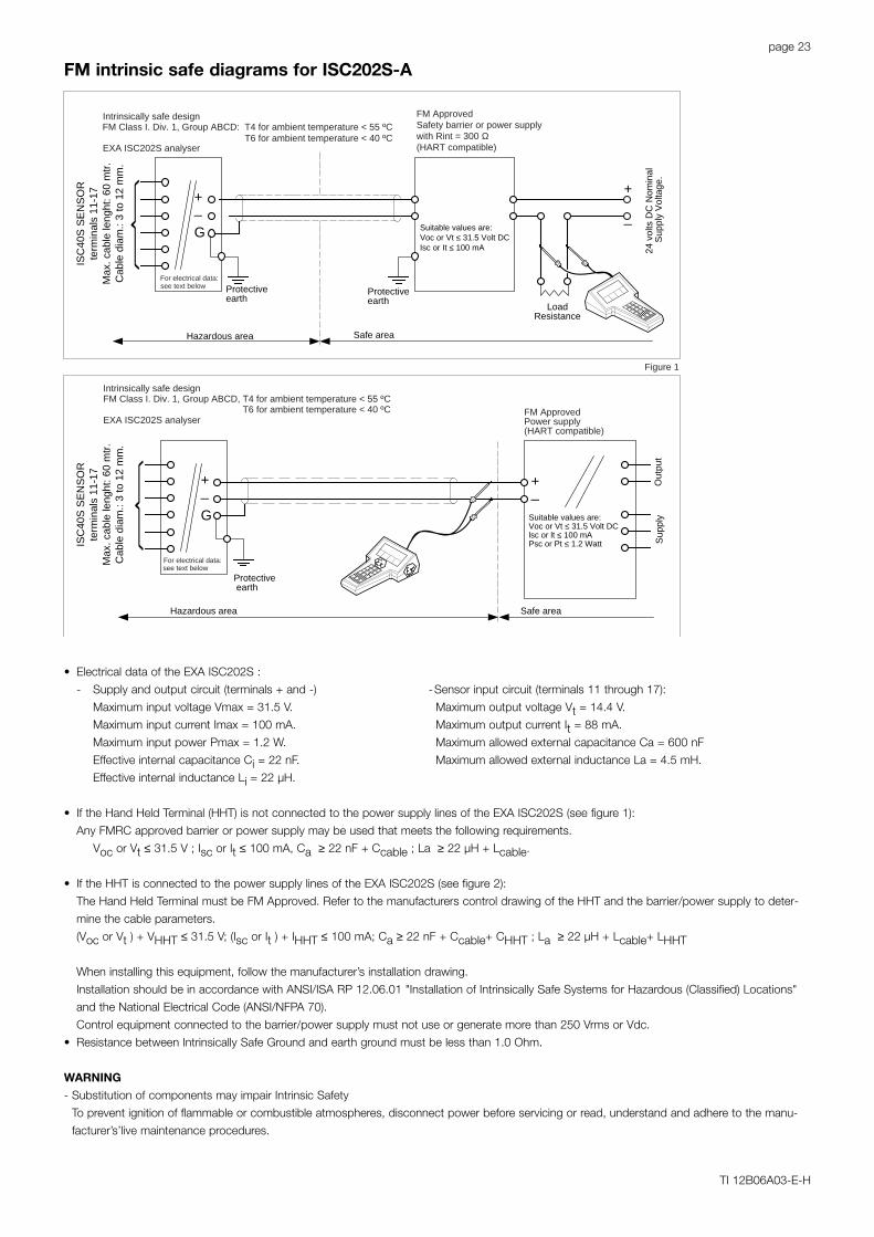
• Electrical data of the EXA ISC202S :
- Supply and output circuit (terminals + and -) -Sensor input circuit (terminals 11 through 17):
Maximum input voltage Vmax = 31.5 V. Maximum output voltage Vt = 14.4 V.
Maximum input current Imax = 100 mA. Maximum output current It = 88 mA.
Maximum input power Pmax = 1.2 W. Maximum allowed external capacitance Ca = 600 nF
Effective internal capacitance Ci = 22 nF. Maximum allowed external inductance La = 4.5 mH.
Effective internal inductance Li = 22 µH.
• If the Hand Held Terminal (HHT) is not connected to the power supply lines of the EXA ISC202S (see figure 1):
Any FMRC approved barrier or power supply may be used that meets the following requirements.
Voc or Vt ≤ 31.5 V ; Isc or It ≤ 100 mA, Ca ≥ 22 nF + Ccable ; La ≥ 22 µH + Lcable.
• If the HHT is connected to the power supply lines of the EXA ISC202S (see figure 2):
The Hand Held Terminal must be FM Approved. Refer to the manufacturers control drawing of the HHT and the barrier/power supply to deter-
mine the cable parameters.
(Voc or Vt ) + VHHT ≤ 31.5 V; (Isc or It ) + IHHT ≤ 100 mA; Ca ≥ 22 nF + Ccable+ CHHT ; La ≥ 22 µH + Lcable+ LHHT
When installing this equipment, follow the manufacturer’s installation drawing.
Installation should be in accordance with ANSI/ISA RP 12.06.01 "Installation of Intrinsically Safe Systems for Hazardous (Classified) Locations"
and the National Electrical Code (ANSI/NFPA 70).
Control equipment connected to the barrier/power supply must not use or generate more than 250 Vrms or Vdc.
• Resistance between Intrinsically Safe Ground and earth ground must be less than 1.0 Ohm.
WARNING
- Substitution of components may impair Intrinsic Safety
To prevent ignition of flammable or combustible atmospheres, disconnect power before servicing or read, understand and adhere to the manu-
facturer’s’live maintenance procedures.
FM intrinsic safe diagrams for ISC202S-A
page 24
TI 12B06A03-E-H
Unclassified Location
+_
G
Classified Location
Protective earth
Intrinsically safe designFM Class I. Div. 2, Group ABCD, T4 for ambient temperature < 55 ºC
T6 for ambient temperature < 40 ºCEXA ISC202S (Analyser)
see text belowFor electrical data:
Classified Location Unclassified Location
+_
G
Protectiveearth
+
_
LoadResistance
FM
App
rove
dpo
wer
sup
ply
VO
C ≤
31.
5 V
DC
Intrinsically safe designFM Class I. Div. 2, Group ABCD: T4 for ambient temperature < 55 ºC
T6 for ambient temperature < 40 ºCEXA ISC202S analyser
For electrical data:see text below
ISC
40S
SE
NS
OR
term
inal
s 11
-17
Max
. cab
le le
ngth
: 60
mtr
.C
able
: 3 to
12
mm
.
ISC
40S
SE
NS
OR
term
inal
s 11
-17
Max
. cab
le le
ngth
: 60
mtr
.C
able
: 3 to
12
mm
.
+
_
FM
App
rove
dpo
wer
sup
ply
VO
C ≤
31.
5 V
DC
Figure 1
Figure 2
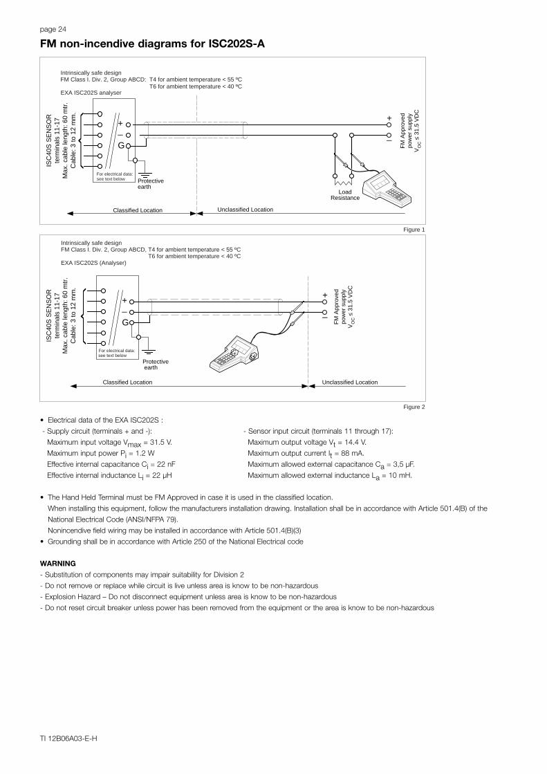
• Electrical data of the EXA ISC202S :
- Supply circuit (terminals + and -): - Sensor input circuit (terminals 11 through 17):
Maximum input voltage Vmax = 31.5 V. Maximum output voltage Vt = 14.4 V.
Maximum input power Pi = 1.2 W Maximum output current It = 88 mA.
Effective internal capacitance Ci = 22 nF Maximum allowed external capacitance Ca = 3,5 µF.
Effective internal inductance Li = 22 µH Maximum allowed external inductance La = 10 mH.
• The Hand Held Terminal must be FM Approved in case it is used in the classified location.
When installing this equipment, follow the manufacturers installation drawing. Installation shall be in accordance with Article 501.4(B) of the
National Electrical Code (ANSI/NFPA 79).
Nonincendive field wiring may be installed in accordance with Article 501.4(B)(3)
• Grounding shall be in accordance with Article 250 of the National Electrical code
WARNING
- Substitution of components may impair suitability for Division 2
- Do not remove or replace while circuit is live unless area is know to be non-hazardous
- Explosion Hazard – Do not disconnect equipment unless area is know to be non-hazardous
- Do not reset circuit breaker unless power has been removed from the equipment or the area is know to be non-hazardous
FM non-incendive diagrams for ISC202S-A
page 25
TI 12B06A03-E-H
SensorConnections
EEx ib[ia] IIC, Certificate no. 01ATEX 1191 XT4 for ambient temperature ≤ 55 ºCT6 for ambient temperature ≤ 40 ºC
Ui = 24 VoltIi = 250 mA
Pi = 1.2 Watt
or Ui = 17.5 VoltIi = 380 mA
Pi = 5.32 Watt
I.S. CertifiedTerminator
EXAISC202S-F
Safe areaApparatus
I.S.Interface
Safe area
Zone 1 Zone 0 or 1
Hazardous area
ATEX
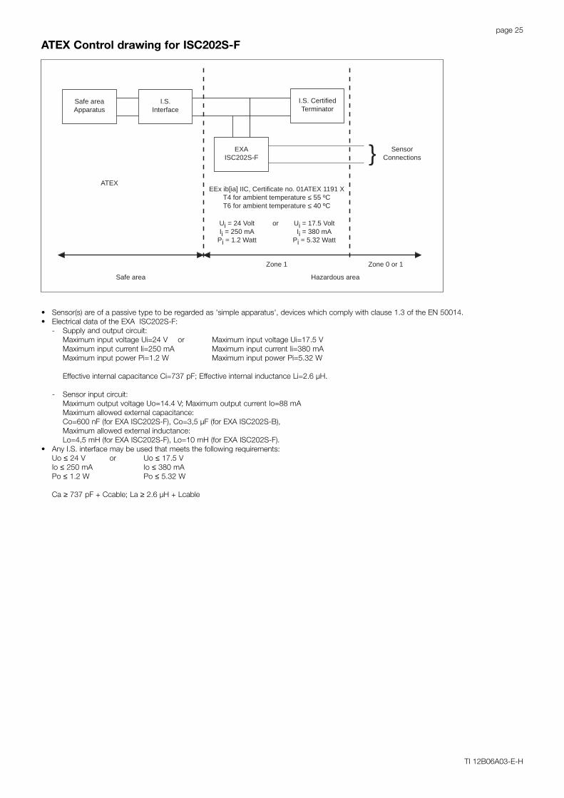
• Sensor(s) are of a passive type to be regarded as 'simple apparatus', devices which comply with clause 1.3 of the EN 50014.• Electrical data of the EXA ISC202S-F:
- Supply and output circuit:Maximum input voltage Ui=24 V or Maximum input voltage Ui=17.5 VMaximum input current Ii=250 mA Maximum input current Ii=380 mAMaximum input power Pi=1.2 W Maximum input power Pi=5.32 W
Effective internal capacitance Ci=737 pF; Effective internal inductance Li=2.6 µH.
- Sensor input circuit:Maximum output voltage Uo=14.4 V; Maximum output current Io=88 mAMaximum allowed external capacitance:Co=600 nF (for EXA ISC202S-F), Co=3,5 µF (for EXA ISC202S-B),Maximum allowed external inductance:Lo=4,5 mH (for EXA ISC202S-F), Lo=10 mH (for EXA ISC202S-F).
• Any I.S. interface may be used that meets the following requirements:Uo ≤ 24 V or Uo ≤ 17.5 VIo ≤ 250 mA Io ≤ 380 mAPo ≤ 1.2 W Po ≤ 5.32 W
Ca ≥ 737 pF + Ccable; La ≥ 2.6 µH + Lcable
ATEX Control drawing for ISC202S-F
page 26
TI 12B06A03-E-H
SensorConnections
CSA Ex ia Class I, DIV. 1, Group ABCDT4 for ambient temperature ≤ 55 ºCT6 for ambient temperature ≤ 40 ºC
Vmax = 24 VoltImax = 250 mA
Pmax = 1.2 Watt
or Vmax = 17.5 VoltImax = 380 mA
Pmax = 5.32 Watt
I.S. CertifiedTerminator
EXAISC202S-F
Safe areaApparatus
I.S.Interface
Safe area
Zone 1 Zone 0 or 1
Hazardous area
CSA
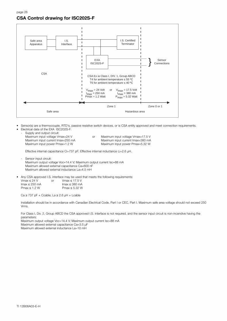
• Sensor(s) are a thermocouple, RTD's, passive resistive switch devices, or is CSA entity approved and meet connection requirements.• Electrical data of the EXA ISC202S-F:
- Supply and output circuit:Maximum input voltage Vmax=24 V or Maximum input voltage Vmax=17.5 VMaximum input current Imax=250 mA Maximum input current Imax=380 mAMaximum input power Pmax=1.2 W Maximum input power Pmax=5.32 W
Effective internal capacitance Ci=737 pF; Effective internal inductance Li=2.6 µH.
- Sensor input circuit:Maximum output voltage Voc=14.4 V; Maximum output current Isc=88 mAMaximum allowed external capacitance Ca=600 nFMaximum allowed external inductance La=4.5 mH
• Any CSA approved I.S. interface may be used that meets the following requirements:Vmax ≤ 24 V or Vmax ≤ 17.5 VImax ≤ 250 mA Imax ≤ 380 mAPmax ≤ 1.2 W Pmax ≤ 5.32 W
Ca ≥ 737 pF + Ccable; La ≥ 2.6 µH + Lcable
Installation should be in accordance with Canadian Electrical Code, Part I or CEC, Part I. Maximum safe area voltage should not exceed 250Vrms.
For Class I, Div. 2, Group ABCD the CSA approved I.S. interface is not required, and the sensor input circuit is non-incendive having theparameters:Maximum output voltage Voc=14.4 V; Maximum output current Isc=88 mAMaximum allowed external capacitance Ca=3.5 µFMaximum allowed external inductance La=10 mH
CSA Control drawing for ISC202S-F
page 27
TI 12B06A03-E-H
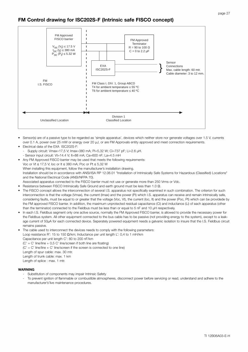
SensorConnectionsMax. cable length: 60 mtr.Cable diameter: 3 to 12 mm.
FM Class I, DIV. 1, Group ABCDT4 for ambient temperature ≤ 55 ºCT6 for ambient temperature ≤ 40 ºC
FM ApprovedTerminator
R = 90 to 100 ΩC = 0 to 2.2 µF
EXAISC202S-F
FM ApprovedFISCO barrier
Voc (Vt) ≤ 17.5 VIoc (It) ≤ 380 mAPoc (Pt) ≤ 5.32 W
Unclassified LocationDivision 1
Classified Location
FMI.S. FISCO
• Sensor(s) are of a passive type to be regarded as 'simple apparatus', devices which neither store nor generate voltages over 1.5 V, currentsover 0.1 A, power over 25 mW or energy over 20 µJ, or are FM Approvals entity approved and meet connection requirements.
• Electrical data of the EXA ISC202S-F:- Supply circuit: Vmax=17,5 V; Imax=380 mA; Pi=5,32 W; Ci=737 pF; Li=2.6 µH.- Sensor input circuit: Vt=14.4 V; It=88 mA; Ca=600 nF; La=4.5 mH
• Any FM Approved FISCO barrier may be used that meets the following requirements:Voc or Vt ≤ 17,5 V; Ioc or It ≤ 380 mA; Poc or Pt ≤ 5,32 WWhen installing this equipment, follow the manufacturer’s installation drawing.Installation should be in accordance with ANSI/ISA RP 12.06.01 "Installation of Intrinsically Safe Systems for Hazardous (Classified) Locations"and the National Electrical Code (ANSI/NFPA 70).Associated apparatus connected to the FISCO barrier must not use or generate more than 250 Vrms or Vdc.
• Resistance between FISCO Intrinsically Safe Ground and earth ground must be less than 1.0 Ω.• The FISCO concept allows the interconnection of several I.S. apparatus not specifically examined in such combination. The criterion for such
interconnection is that the voltage (Vmax), the current (Imax) and the power (Pi) which I.S. apparatus can receive and remain intrinsically safe,considering faults, must be equal to or greater that the voltage (Voc, Vt), the current (Ioc, It) and the power (Poc, Pt) which can be providede bythe FM approved FISCO barrier. In addition, the maximum unprotected residual capacitance (Ci) and inductance (Li) of each apparatus (otherthan the terminator) connected to the Fieldbus must be less than or equal to 5 nF and 10 µH respectively.
• In each I.S. Fieldbus segment only one active source, normally the FM Approved FISCO barrier, is allowed to provide the necessary power forthe Fieldbus system. All other equipment connected to the bus cable has to be passive (not providing energy to the system), except to a leak-age current of 50µA for each connected device. Seperately powered equipment needs a galvanic isolation to insure that the I.S. Fieldbus circuitremains passive.
• The cable used to interconnect the devices needs to comply with the following parameters:Loop resistance R’: 15 to 150 Ω/km; Inductance per unit length L’: 0,4 to 1 mH/kmCapacitance per unit length C’: 80 to 200 nF/km(C’ = C’ line/line + 0,5 C’ line/screen if both line are floating)(C’ = C’ line/line + C’ line/screen if the screen is connected to one line)Length of spur cable: max. 30 mtr.Length of trunk cable: max. 1 kmLength of splice : max. 1 mtr.
WARNING- Substitution of components may impair Intrinsic Safety- To prevent ignition of flammable or combustible atmospheres, disconnect power before servicing or read, understand and adhere to the
manufacturer’s’live maintenance procedures.
FM Control drawing for ISC202S-F (Intrinsic safe FISCO concept)
page 28
TI 12B06A03-E-H
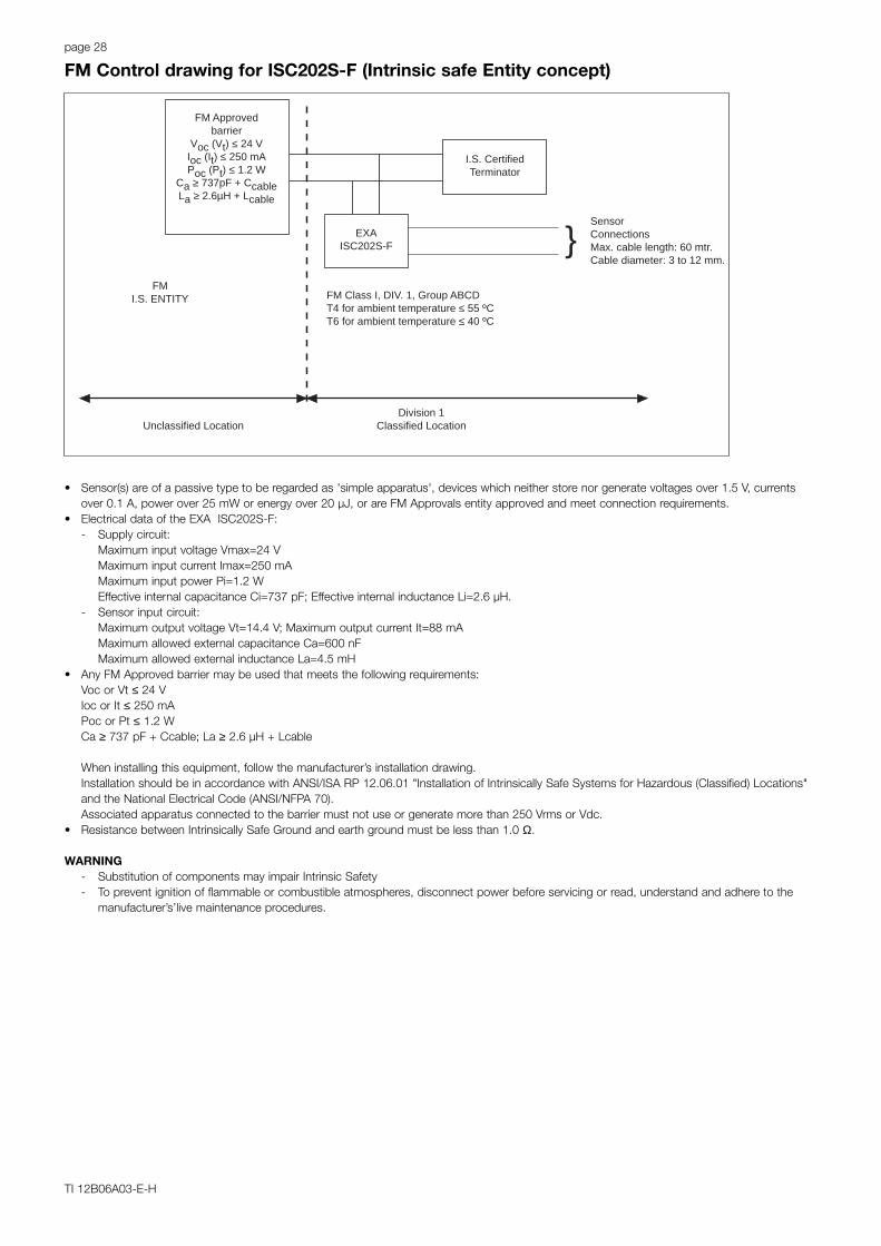
SensorConnectionsMax. cable length: 60 mtr.Cable diameter: 3 to 12 mm.
FM Class I, DIV. 1, Group ABCDT4 for ambient temperature ≤ 55 ºCT6 for ambient temperature ≤ 40 ºC
I.S. CertifiedTerminator
EXAISC202S-F
FM Approvedbarrier
Voc (Vt) ≤ 24 VIoc (It) ≤ 250 mAPoc (Pt) ≤ 1.2 W
Ca ≥ 737pF + CcableLa ≥ 2.6µH + Lcable
Unclassified LocationDivision 1
Classified Location
FMI.S. ENTITY
• Sensor(s) are of a passive type to be regarded as 'simple apparatus', devices which neither store nor generate voltages over 1.5 V, currentsover 0.1 A, power over 25 mW or energy over 20 µJ, or are FM Approvals entity approved and meet connection requirements.
• Electrical data of the EXA ISC202S-F:- Supply circuit:
Maximum input voltage Vmax=24 VMaximum input current Imax=250 mAMaximum input power Pi=1.2 WEffective internal capacitance Ci=737 pF; Effective internal inductance Li=2.6 µH.
- Sensor input circuit:Maximum output voltage Vt=14.4 V; Maximum output current It=88 mAMaximum allowed external capacitance Ca=600 nFMaximum allowed external inductance La=4.5 mH
• Any FM Approved barrier may be used that meets the following requirements:Voc or Vt ≤ 24 VIoc or It ≤ 250 mAPoc or Pt ≤ 1.2 WCa ≥ 737 pF + Ccable; La ≥ 2.6 µH + Lcable
When installing this equipment, follow the manufacturer’s installation drawing.Installation should be in accordance with ANSI/ISA RP 12.06.01 "Installation of Intrinsically Safe Systems for Hazardous (Classified) Locations"and the National Electrical Code (ANSI/NFPA 70).Associated apparatus connected to the barrier must not use or generate more than 250 Vrms or Vdc.
• Resistance between Intrinsically Safe Ground and earth ground must be less than 1.0 Ω.
WARNING- Substitution of components may impair Intrinsic Safety- To prevent ignition of flammable or combustible atmospheres, disconnect power before servicing or read, understand and adhere to the
manufacturer’s’live maintenance procedures.
FM Control drawing for ISC202S-F (Intrinsic safe Entity concept)

page 29
TI 12B06A03-E-H
SensorConnectionsMax. cable length: 60 mtr.Cable diameter: 3 to 12 mm.
FM Class I, DIV. 2, Group ABCDT4 for ambient temperature ≤ 55 ºCT6 for ambient temperature ≤ 40 ºC
FM Approvedterminator
R = 90 to 100 ΩC = 0 to 2.2 µF
EXAISC202S-B
FM ApprovedPower supplyVoc ≤ 32 VDC
Unclassified LocationDivision 2
Classified Location
FMN.I. FISCO
• Sensor(s) are of a passive type to be regarded as 'simple apparatus', devices which neither store nor generate voltages over 1.5 V, currentsover 0.1 A, power over 25 mW or energy over 20 µJ, or are FM Approvals entity approved and meet connection requirements.
• Electrical data of the EXA ISC202S-B:- Supply circuit: Vmax=32 V; Pi=5.32 W; Ci= 737 pF; Li= 2.6 µH- Sensor input circuit: Vt=14.4 V; It=88 mA; Ca=3,5 µF; La=10 mHWhen installing this equipment, follow the manufacturers installation drawing.Installation shall be in accordance with Article 501.4(B) of the National Electrical Code (ANSI/NFPA 79). Nonincendive field wiring may beinstalled in accordance with Article 501.4(B)(3)
• Grounding shall be in accordance with Article 250 of the National Electrical code.
WARNING- Substitution of components may impair suitability for Division 2.- Do not remove or replace while circuit is live unless area is know to be non-hazardous- Explosion Hazard – Do not disconnect equipment unless area is know to be non-hazardous- Do not reset circuit breaker unless power has been removed from the equipment or the area is know to be non-hazardous
FM control drawing for ISC202S-B (Non-incendive FISCO concept)
page 30
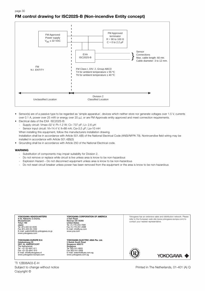
SensorConnectionsMax. cable length: 60 mtr.Cable diameter: 3 to 12 mm.
FM Class I, DIV. 2, Group ABCDT4 for ambient temperature ≤ 55 ºCT6 for ambient temperature ≤ 40 ºC
FM Approvedterminator
R = 90 to 100 ΩC = 0 to 2.2 µF
EXAISC202S-B
FM ApprovedPower supplyVoc ≤ 32 VDC
Unclassified LocationDivision 2
Classified Location
FMN.I. ENTITY
• Sensor(s) are of a passive type to be regarded as 'simple apparatus', devices which neither store nor generate voltages over 1.5 V, currentsover 0.1 A, power over 25 mW or energy over 20 µJ, or are FM Approvals entity approved and meet connection requirements.
• Electrical data of the EXA ISC202S-B:- Supply circuit: Vmax=32 V; Pi=1.2 W; Ci= 737 pF; Li= 2.6 µH- Sensor input circuit: Vt=14.4 V; It=88 mA; Ca=3,5 µF; La=10 mHWhen installing this equipment, follow the manufacturers installation drawing.Installation shall be in accordance with Article 501.4(B) of the National Electrical Code (ANSI/NFPA 79). Nonincendive field wiring may beinstalled in accordance with Article 501.4(B)(3)
• Grounding shall be in accordance with Article 250 of the National Electrical code.
WARNING- Substitution of components may impair suitability for Division 2.- Do not remove or replace while circuit is live unless area is know to be non-hazardous- Explosion Hazard – Do not disconnect equipment unless area is know to be non-hazardous- Do not reset circuit breaker unless power has been removed from the equipment or the area is know to be non-hazardous
FM control drawing for ISC202S-B (Non-incendive Entity concept)
`TI 12B06A03-E-HSubject to change without notice Printed in The Netherlands, 01-401 (A) QCopyright ©
YOKOGAWA
YOKOGAWA EUROPE B.V.Databankweg 203821 AL AMERSFOORTThe NetherlandsTel. +31-33-4641 611Fax +31-33-4641 610E-mail: [email protected]
YOKOGAWA CORPORATION OF AMERICA2 Dart RoadNewnan GA 30265United StatesTel. (1)-770-253-7000Fax (1)-770-251-2088E-mail: [email protected]
YOKOGAWA ELECTRIC ASIA Pte. Ltd.5 Bedok South RoadSingapore 469270SingaporeTel. (65)-241-9933Fax (65)-241-2606E-mail: [email protected]
YOKOGAWA HEADQUARTERS9-32, Nakacho 2-chome,MusashinoshiTokyo 180JapanTel. (81)-422-52-5535Fax (81)-422-55-1202E-mail: [email protected]
Yokogawa has an extensive sales and distribution network. Pleaserefer to the European web-site (www.yokogawa-europe.com) tocontact your nearest representative.


![User’s Manual Model PH202G [Style: S3], PH202S [Style: S3] 2-wire Type pH… · 2020. 4. 10. · User’s Manual Model PH202G [Style: S3], PH202S [Style: S3] 2-wire Type pH/ORP(Redox)](https://static.documents.pub/doc/80x56/5fcf4263cb758459f013f8a8/useras-manual-model-ph202g-style-s3-ph202s-style-s3-2-wire-type-ph-2020.jpg)


