20
Manufactured by M Metal Pte Ltd under license from Fielders Australia Pty Ltd RF55 ® STRUCTURAL DECKING You Inspire, We Deliver.
| Date post: | 28-Jul-2018 |
| Category: |
Documents |
| Upload: | truongminh |
| View: | 215 times |
| Download: | 0 times |

Manufactured by M Metal Pte Ltd under
license from Fielders Australia Pty Ltd
RF55®
STRUCTURALDECKING
You Inspire , We Deliver.

RF55® is a traditional flat pan or ‘re-entrant’ profile that
provides unmatched performance in suspended concrete
slabs. RF55® is used in both concrete and steel frame
construction and utilizes patented technology to
achieve superior spanning capabilities, less deflection
and greater composite strength than similar re-entrant
profiles.
RF55® can deliver cost savings when used in the following
types of construction:
• Concrete frame buildings
• Residential construction
• Multi-level carparks and Multi-storey buildings.
• Commercial buildings.
• Shopping centres.
RF55®
Structural Decking Introduction
M Metal is a Singapore-based manufacturer of high quality steel and non-steel roofing and walling products. We also manufacture Galvanised Hi-Tensile steel decking - RF55® and MDEK S100™.
We started the company in 2007 in response to what we saw was a growing industry need for a responsible supplier, which believes in the value of forging partnerships with stakeholders in order to deliver innovative, reliable and customized solutions. It is our breadth and depth of specialized knowledge, combined with our stakeholders’ awareness of their client needs, which results in a win-win collaboration.
Our sense of responsibility extends to workplace safety. We strongly believe that good safety equates good business. Through regular training sessions, we make sure that our workers, and also those of our contractors, are able to do a good job safely.
Staffed by experienced professionals with an in-depth knowledge of the industry and who are motivated by the company’s vision - to be the industry’s preferred building solutions provider from concept to completion - we aim to be a game-changer in Singapore’s building industry.
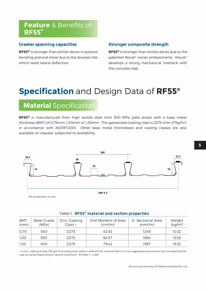
RF55® is manufactured from high tensile steel (min 500 MPa yield stress) with a base metal
thickness (BMT) of 0.75mm, 1.00mm or 1.20mm. The galvanized coating class is Z275 (min 275g/m2)
in accordance with AS1397:2001. Other base metal thicknesses and coating classes are also
available on request, subjected to availability.
Material Specification
*All dimensions in mm.
Greater spanning capacities
RF55® is stronger than similar decks in positive
bending and end shear due to the dovetail ribs
which resist lateral deflection.
Stronger composite strength
RF55® is stronger than similar decks due to the
patented ReLok® corner embossments. ReLok®
develops a strong mechanical interlock with
the concrete slab.
Feature & Benefits of RF55®
Specification and Design Data of RF55®
3
All pictures courtesy of Fielders Australia Pty Ltd
Table 1: RF55® material and section properties
BMT Steel Grade Zinc Coating 2nd Moment of Area X- Sectional Area Weight(mm) (MPa) Class + (cm4/m) (mm2/m) (kg/m2)
0.75 550 Z275 42.82 1248 10.32
1.00 550 Z275 64.57 1664 13.56
1.20 500 Z275 79.42 1997 16.32
+ A zinc coating of total 275 g/m2 (including both sides) is sufficient for internal floors in a non-aggressive environment, but the specification may be varied depending on service conditions – EN1994-1-1 4.2(3)

Table 3 : Factored load combinations for strength & deflection calculations
Construction Design Imposed Dead Load Imposed Construction Load
Stage Criterion Decking Wet Concrete Construction Storage
1A Strength 1.35 - 1.5 -
1B Strength 1.35 - - 1.5
2A Strength 1.35 1.35 1.5 -
2B Deflection 1.0 1.0 - -
Span Table Notes• The tables above denote maximum allowable centerline to centerline span (in mm) between supports.• Density of wet concrete is assumed at 2400 kg/m3.• Loading configurations during the various construction stages are considered in accordance with EN1994.• Construction load of 1.5kPa is adopted.• The deflection limit adopted is Span/130. For exposed soffit, a deflection limit of Span/240 is recommended.• A minimum bearing width of 50mm of the permanent steel support and 125mm flange width have been considered.• When using the table for 2 or more spans the adjacent spans should not differ in length by more than 5%.• M Metal recommends a gauge of 1.00mm BMT for exposed soffit in propped applications to avoid creasing of steel decking. Please contact our sales & marketing department for further information.• Care must be exercised when placing concrete to avoid mounding.• Wide ply strips, of 300mm wide, shall be provided to prevent any concentrated loads being applied to the sheeting to avoid direct point loading of the sheet overlap ribs and unsupported edges of the sheeting.
Table 2 : RF55® Maximum un-propped span
BMT 0.75mm
Slab thickness (Dcs) 110 120 130 150 175 200 250
Single Span 2500 2450 2400 2300 2200 2100 1800
Continuous 3000 2900 2800 2600 2400 2200 1850
BMT 1.00mm
Slab thickness (Dcs) 110 120 130 150 175 200 250
Single Span 2900 2850 2800 2700 2550 2450 2300
Continuous 3700 3600 3500 3350 3150 3000 2750
BMT 1.20mm
Slab thickness (Dcs) 110 120 130 150 175 200 250
Single Span 3100 3000 2950 2850 2700 2600 2450
Continuous 4050 3950 3850 3650 3500 3300 3050
RF55® is developed to work as formwork during the construction stage. RF55® formwork design is based on EN1993-1-3. RF55®’s symmetrical lapped ribs and RE-Lok® embossments features allows it to span longer than other types of re-entrant profile.
The span table below shows the maximum un-propped span for RF55® installed in single or continuous spans. The table should be read in conjunction with Span Table Notes below. For other spanning configuration, please contact our sales and marketing department for more information.
Formwork Span Design

Figure 1 Cross section showing temperature contour for 240 minutes
A 3D finite element model has been conducted at HERA (Heavy Engineering Research Association). The finite element analyses (uncoupled heat transfer procedures) were carried out on a 200mm x 200mm x 170mm deep block of slab based on the following conditions;
• The RF55® deck and reinforcement bars are fully bonded to the concrete.• Temperature dependent material properties according to EN 1994-1-2 were used for the normal weight concrete and steel.• Emissivity of 0.7 & 1.0 (conservative) was assigned to the concrete and deck face, respectively (the former value is taken from EN 1002-1-2)• The standard temperature-time curve given in EN1991-1-2 and ISO 834 was used to heat up the bottom deck face.
Fire resistance for RF55® composite slab is designed in accordance to EN1994-1-2. The recommended location for fire reinforcement is shown in figures below. Typically, the mesh or rebars are
laid with the longitudinal rebars evenly spaced between the ribs support by the distribution rebars (cross bars).
Please contact our sales and marketing department should you require more information on the design of composite slab.
Table 4 : Minimum Concrete thickness above ribs, hc
Non-composite beam Composite beam Action Action
40mm 50mm
RF55® composite slab is designed in accordance to EN1994-1-1 Section 9, EN1993-1-3. The design method is based on m&k values. Data about longitudinal shear capacity have been obtained from full scale tests conducted in Nanyang Technological University.
The minimum overall depth of the composite slab Dcs, shall be determined according to the conditions indicated in the table below. – EN1994-1-1 9.2.1
5
Composite Slab Design
Fire Resistance Design
For Type B & D Mesh For Type A Mesh

Composite slabs and beams are most commonly used in commercial and industrial buildings due to the speed and economy of construction. Savings in beam weight can be achieved when the composite slab is effectively anchored to the steel beam. The slab will then act as a compression flange whilst the steel beam acts as a tension member.
Composite beams are normally hot rolled or fabricated steel sections acting compositely with the concrete slab. Composite interaction is achieved by the attachment of shear connectors to the top of the beam. These connectors generally take the form of headed studs and can be welded in the workshop or on-site through the decking. It is recommended the shear studs to be welded on site, as this will allow for continuity of the decking sheets and more economical designs. The shear connectors are required to provide sufficient longitudinal shear connection between the beam and the concrete so that they act together compositely.
Design of Shear Connectors
• Shear Connectors Location Details Some profiles on the market (typically trapezoidal profile) have a central location of the lapping rib which creates a ‘preferred’ and a ‘non-preferred’ side of the rib to place the shear stud to obtain optimum capacity of the shear stud. This creates unnecessary complexity for sub contractors on site to be able to distinguish the most beneficial placement of the stud.
For RF55®, the centre of the pan is flat and thus allows the shear studs to be placed centrally in the pan on all occasions to simplify design and installation.
Although a temperature differential exists between the concrete above the dovetail and the solid section of the slab, it will not penetrate a significant distance into the rib. The distribution rebars will have a significant thermal gradient so the temperature of the longitudinal rebars will still be principally a function of their axis distance. In summary, the flow of heat through the top of the re-entrant portions of the deck into the transverse reinforcement would have a small effect on the resistance of the longitudinal reinforcement in fire conditions.
The results of the FEA shows that the presence of the cross-bars increases the temperatures in the longitudinal rebars and concrete. However, the influence is minor with an increase of 4% for the typical fire period of 120 minutes.
Model with one longitudinal rebar
Model with one longitudinal rebar and cross rebar
The detail FEA report is available upon request. Kindly contact our sales & marketing department for more information.
Composite Steel Beam Design

Table 6 : Minimum Composite Slab thickness (Based on 19mmx 100mm shear connector)
Profile Rib Height Min hc Shear connector hsc Min Conc. Cover Min Slab thk = Greater (A) (B)^ (C) (D) of (A+B) ; (C+D)
Trapezoidal 40 50 100 20 120
RF55® 55 50 100 20 120
Flat 100 50 150 20 170
^ from Table 4
• Minimum Composite Slab Thickness The minimum composite sl ab t hickness with composite beam action depends on the height of the shear connectors and the concrete cover over the shear connectors.
EN 1994 6.6.5.2 (2) recommends the fo l lowing concrete cover over the shear connectors: • Not less than 20mm, or • As recommended by EN 1992-1-1, Table 4.4 for reinforcing steel, whichever is greater.
However, if cover is not required the top of the connector may be flush with the upper surface of the concrete slab. This shall be determined by the structural engineer.
Typical ly , for a RF55® composite slab, 19mm (d) x 100mm (L) shear connectors are used in the composite beam design. With 20mm concrete cover over the connector, the minimum RF55® composite slab shall be;• hsc + 20mm, or• hp + 50mm, whichever is greater (EN1994-1-1 9.2.1)
^ based on what is the standard dimension available in the market.
Deck Rib Height, hp Diameter, d Min Stud Height, RecommendedProfile (mm) (mm) hsc = hp+2d (mm) Studs Height^, hsc
Trapezoidal 40 19 40+2*19 =78 100mm
RF55® 55 19 55+2*19 = 93 100mm
Flat 100 19 100+2*19 =138 150mm
Table 5 : Recommended Shear Standard height, hsc
The nominal height of a shear stud hsc, should extend not less than 2d above the top of the steel deck, where d is the diameter of the shank. - EN1994-1-1 6.6.5.8 (1).
The table below illustrates the minimum height of a shear connector depending on the type of profile steel deck used in composite slab composite beam design.
• Minimum Height of Shear Connectors, hsc
7

Table 7 : Decibel Rating System
Sound Pressure Level (dB) Description of Activity Typical Subjective Description
0 Threshold of hearing Absolute silence
20 Whispering at one metre Very quiet
40 Quiet residential neighbourhood Quiet
60 Conversation at one metre Moderately noisy
80 Shouting Noisy
100 Heavy Industry Very noisy
120 Heavy gun-fire Intolerable
Acoustics and noise transfer in buildings are becoming important issues in the construction industry. There are several issues that must be understood to fully appreciate the transfer of noise. Noise is an airborne vibration, which has an effect on the eardrum. Noise has two characteristics: its level and its frequency.
There are two types of noise: airborne and impact sound. Airborne sounds are those that are transferred in the air. These noises include traffic, conversations, and music. Impact sounds are those that are propagated in the walls and floors of a building and include noise such as footsteps and drills. Most noises encountered in a building consist of both airborne and impact sounds.
The two major influences in the transfer of noise are absorption and reflection. There are three main areas in a room that influence the transfer of the noise, ceiling, walls and floors (for a suspended floor).
• The ceiling is the major sound surface in many rooms. As the room size increases so does the importance of the ceiling. Ceilings in a commercial application are often constructed from or covered by some form of sound
Understanding the transfer of noise
absorbing mineral material. However, these do not provide a uniform surface (eg. Joints between panels, light fittings). Flat lucite/ perspex lenses over fluorescent tubes are the worst fittings for sound reflection. Parabolic, deep cell diffusers are the best sound absorption.
• Walls – these are usually the next most influential surface. Their importance increases as room size decreases. Typically walls have very poor sound absorbing qualities and this is often made worse by putting sound reflectors against walls e.g. filing cabinets.
• Floor – carpeting the floor will only slightly increase the NRC (Noise Reduction Coefficient). Moving to thicker carpeting is often not a cost-effective solution because much of the floor area is covered with furniture with a worse NRC. Carpeting will however reduce impact noise.
It must be understood that the decibel rating is a logarithmic scale. The mass law equation predicts that each time the frequency of measurement or the mass per unit area of a single layer wall is doubled, the transmission loss increases by about 6dB.
Acoustic Performance of RF55® Slabs

Effects of Systems
If a higher Rw value is necessary, and it often is in higher quality construction, it is not economical to continually double the wall or floor thickness to achieve it. Double layer assemblies are a more practical way of getting high Rw values without excessive weight.
A built-up steel cladding system comprises an external profiled steel sheet, a perforated or non-perforated internal liner sheet and an infill between the two sheets, such as mineral fibre. The transmission loss of such a system can be modified in a number of ways:
• The total mass can be increased by using a denser or thicker layer of infill.
• Better performance is possible through using dense, soft rolls of mineral fibre infills, rather than rigid ones.
• Transmission loss is also improved via an air- gap inside the outer face of the cladding as it minimizes transmission of reverberations from the external sheets to the insulation.
If sound absorption in a room is important, then the internal sheet of the cladding system should be perforated to allow deadening by the insulation. However this can also have a reverse effect on the transmission loss characteristics of a structure.
The ideal double layer assembly has no rigid mechanical connection between its two surfaces. Rigid mechanical connections are the acoustical equivalent of an electrical short circuit or a thermal bridge in an insulated wall and should be avoided.
The mechanical connection between layers of wall-board can be reduced by the use of staggered wood studs, separate rows of wood studs, or a single row of wood studs with resilient metal furring channels to support the wallboard layers independently of each other. Non-load-bearing steel studs are usually resilient enough to provide adequate mechanical decoupling between the layers. Good results have also been obtained using 150mm load-bearing steel studs in conjunction with resilient channels.
Connection between a floor system and a ceiling should be via acoustic resilient mounts. Small openings, such as fixing points and penetrations, allow airborne sound to pass through the element. Therefore to increase the insulation properties of the element it is important for that element to be airtight. To seal perimeters and penetrations for services and dense, flexible material such as mastic should be used. For areas where large movement is expected, a polyurethane fire and acoustic rated sealant should be used. RF55® slabs have the same acoustic performance as a solid concrete slab of the same thickness.
A good rule of thumb is the stiffer the panel, the more sound it will transmit. A profile steel sheet of a given thickness can produce the same structural strength of a flat panel of substantially greater weight and thickness. That is because a profiled panel will have a higher bending stiffness than a flat one.
Acoustical data is usually quoted in terms of either sound absorption or sound transmission. Sound transmission loss is the more relevant value and is expressed as a function of frequency. This is Rw (alternatively known as sound transmission coefficient) and it is given for a particular material. It is measured in decibels.
Concrete
A single layer of poured concrete 150mm thick gives an Rw of about 55.
Effects of Materials
The acoustic behavior of materials is influenced by several parameters; its mass, reactivity, and vibration absorption. The increased weight per unit area of panel decreases sound transmission. The increased frequency of incident sound decreases sound transmission. Apart from the mass of the panel other factors that affect sound transmission are:
• Panel stiffness – at very low frequencies the stiffness (i.e. resistance to deformation) may have more effect than its weight. In this part of the frequency range insulation is termed stiffness controlled.
• Rigid panels – if a rigid panel is struck it will continue to vibrate at frequencies determined by its size, shape, and thickness – this is its “natural frequency”.
9

Distance between the Bottom of Pan and the Underside of the Pre-stressing Conducit
Distance between the Bottom of Pan and the Underside of the Pre-stressing Conducit
Table 8 Minimum Distance (D)
Between Bottom of the Pan and underside of the conduit – Tendons
Parallel to rib
FR Simply Supported Continuous Flat Slabs(min) (mm) (mm) (mm)
120 45 25 35
180 70 45 60
240 85 55 80
Table 9 Minimum Distance (D)
Between Top of the rib and underside of the conduit – Tendons Perpendicular to rib
FR Simply Supported Continuous Flat Slabs (min) (mm) (mm) (mm)
120 12 0 8
180 20 5 15
240 35 10 25
When post-tensioned slabs are designed in conjunction with steel decking it is important to consider the location of the conduits to that of the ribs. The location of the conduits is important for determining the heat transfer in the event of a fire from the rib to the tendons. Analytical results using the heat transfer program Tasef-2, developed by Lund Institute of Technology, Sweden and the results from relevant testing have been used to determine the adequacy of the placement of post- tensioning tendons with re-entrant profiles.
The location of the post tensioned conduit for RF55® composite slabs are determined in order to not exceed the limiting steel temperatures of 450˚C (simply supported), 520˚C (flat slab) and 650˚C (continuous) to ensure consistency with current and future versions of AS3600:2001. For the case of tendons having parallel orientation to the deck it is assumed that the conduit is located centrally between RF55® ribs. This gives a distance from the centerline of the rib to the edge of the conduit of 60mm, and to the centerline of the tendon closest to the edge of the conduit of 72mm.
The required distances from the heated soffit to the bottom of the conduit have been determined using Tasef-2 analyses previously undertaken for RF55®. The limiting distances to the edge of the conduit to achieve the nominated FRL are summarized in Table 2.C and relate to the edge of the conduit being located a minimum distance between the exterior of the top of the rib and the edge of the conduit being greater than or equal to 30mm. The slab thickness has been assumed to be 140mm but the results can be considered to be applicable to the range of practical post- tensioned concrete slabs.
For the case of tendons having perpendicular orientation to the deck the location of the conduit is required to be greater than that for the parallel orientation. Using the Tasef-2 analysis results for RF55®, the minimum distances between the top of rib and the underside of a conduit to achieve a required FR are given in the table below.
Post Tensioning Composite Slabs

Concrete should be placed in a manner that minimizes the permanent deflection of the decking. When concreting is poured in the same direction as the span of the decking it should be placed first over the supports where the decking is continuous, followed by the mid span region and finally the areas above the end supports. When concrete is being poured transversely to the decking ribs, it should be placed first at the edge where a decking sheet is supported by the under lap of an adjacent sheet. This will help ensure that the longitudinal seams between sheets remain closed.
When a steel deck composite slab is to be poured in conjunction with a band beam, it is the contractor’s responsibility to ensure that the temporary ply used to form the concrete beam is positioned, held & secured sufficiently to form the beam to engineer’s details. The steel deck must pass the ply form of the beam a minimum
Panels are delivered to site or specified storage area, in strapped bundles. If not required for immediate use, bundles should be neatly stacked clear of the ground with a fall for drainage and protected by waterproof covers. Do not allow rain or condensation to be trapped between panels. Length manufactured according to shop drawings.
To minimize damage to the sheets, break open bundles only when installation is due to commence. Check to ensure that any temporary supports required are in place prior to installing the decking.
When lifting, it is recommended that appropriate lifting equipments are used. Unprotected chain slings can damage the bundle during lifting. When synthetic slings are used there is a risk of severing them on the edges of the decking sheets.
of 50mm. Care must be taken that the steel deck does not penetrate into the band beam to such an extent that it fowls the internal reinforcing used in the band beam.
If timber packers are used, they should be secured to the bundle before lifting so that when slings are released they do not fall to the ground. Bundles must never be lifted using the metal banding.
We can provide comprehensive design advice and information pertaining to the application, handling & installation of RF55® structural steel decking and edge form. Please contact M Metal if you require technical support.
11
Storage And Handling
Concrete Placing
Technical Support
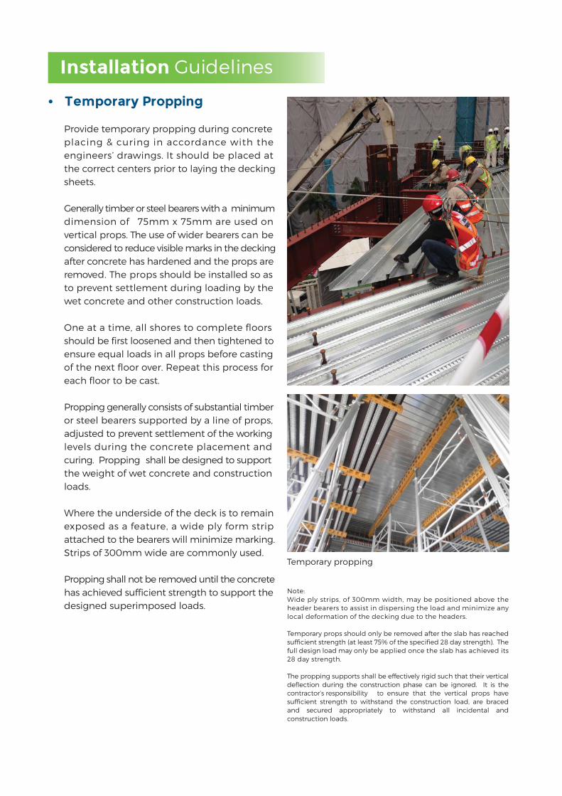
Note: Wide ply strips, of 300mm width, may be positioned above the header bearers to assist in dispersing the load and minimize any local deformation of the decking due to the headers.
Temporary props should only be removed after the slab has reached sufficient strength (at least 75% of the specified 28 day strength). The full design load may only be applied once the slab has achieved its 28 day strength.
The propping supports shall be effectively rigid such that their vertical deflection during the construction phase can be ignored. It is the contractor’s responsibility to ensure that the vertical props have sufficient strength to withstand the construction load, are braced and secured appropriately to withstand all incidental and construction loads.
• Temporary Propping Provide temporary propping during concrete placing & curing in accordance with the engineers’ drawings. It should be placed at the correct centers prior to laying the decking sheets.
Generally timber or steel bearers with a minimum dimension of 75mm x 75mm are used on vertical props. The use of wider bearers can be considered to reduce visible marks in the decking after concrete has hardened and the props are removed. The props should be installed so as to prevent settlement during loading by the wet concrete and other construction loads.
One at a time, all shores to complete floors should be first loosened and then tightened to ensure equal loads in all props before casting of the next floor over. Repeat this process for each floor to be cast.
Propping generally consists of substantial timber or steel bearers supported by a line of props, adjusted to prevent settlement of the working levels during the concrete placement and curing. Propping shall be designed to support the weight of wet concrete and construction loads.
Where the underside of the deck is to remain exposed as a feature, a wide ply form strip attached to the bearers will minimize marking. Strips of 300mm wide are commonly used.
Propping shall not be removed until the concrete has achieved sufficient strength to support the designed superimposed loads.
Temporary propping
Installation Guidelines

• Reinforcement
Place all reinforcement in strict accordance with the structural engineer’s drawings and specification.
• Concrete Placement
The specified grade of concrete and any chemical admixtures must be in accordance with EN 1992 and the structural engineer’s drawings and specification. The deck must be clear of any excess dirt, grease or debris as this inhibits bonding between the deck and concrete reducing the floor slab capacity.
Ensure that the concrete is applied evenly over the decking surface, as mounding of the wet concrete will cause excessive local loading and deflection.
Fixing at end supports
Fixing over intermediate supportsFixing over intermediate supports
• Fasteners and locations
The decking must be positively fixed to the supporting structure, in order to avoid movement and excessive deflection during the pouring of concrete.
When fixing to a steelwork support structure, shot fired pins or self drilling/tapping fasteners should be used. Provide 1 fastener in each pan at every support. Place the fixings in the flat areas of the pans adjacent to the ribs or between the flutes.
In the case of other support systems, such as brickwork, blockwork and concrete, the decking must be temporarily held in place against wind and other effects until the concrete is poured.
Fixing panels to masonry supports may not be necessary if concrete is placed immediately after panels are laid. If fixing is required to prevent movement due to wind or for safety reasons during placement of concrete, the panels should be secured to the temporary timber bearers by nailing.
• Laying of Decking
Panels should be accurately aligned, side laps fully lapped and the gap between abutting ends kept to a minimum.
Provision should be made so that all panels have full end and intermediate bearing support on the building framework of a minimum of 50mm unless other stated on the structural
drawings. If supporting on a brick or masonry wall, provide a separating strip such as a malthoid.
The decking must be continuous over all intermediate temporary supports without intermediate splicing or joining. Sheeting shall only terminate at ends into a permanent support (i.e. steel beam or concrete beam).
13

Cutting & Penetrations
Panels are supplied at the required lengths to minimize on-site cutting. Where necessary, panels can be cut using a power saw with an abrasive disc or a metal cutting friction blade. When cutting, panels should be turned over with the ribs downwards.
Where holes are to be cut for pipes etc, the use of hole-saw is recommended. Should it be necessary to provide a hole through the floor decking, the sheeting should only be cut after curing of the concrete cured (i.e. the concrete has reached a minimum of 75% of its design strength). Before the actual concrete pour, any openings should be boxed out with timber shuttering or dense polystyrene blocks.
For isolated openings at right angles to the deck span, M Metal offers the following guidelines which must always be checked and approved by the structural engineers:
• Penetrations up to 200mm square may be acceptable without additional reinforcement.
• Penetrations between 200mm & 500mm square may require additional reinforcement to trim the opening, designed in accordance. • Penetrations greater than 500mm square typically require trimming steelwork support to be supplied by the fabricator.
• A close group of penetrations transverse to the profile direction should be considered as single large penetration.
Permanent Loading
Do not place permanent loads, including masonry walls, on the concrete structure until the concrete has cured and all props have been removed.
Construction Loading
In accordance with EN1994, the maximum construction is 1.5 kPa or 4.5/Span kPa for span less than 3m. Do not place construction loads, including plant and equipment, on the concrete structure, which exceeds the design capacity of the structure. Seek permission for such loads.
Applying loads on decking

Accessories – Edge form/Flashings An easy & economical method of forming up the edges of concrete slabs is to order the edge form from M Metal. It is custom made from galvanized steel in lengths of about 3 metres long.
The bottom edge of the form is slipped between the decking, and the beam or wall below. The top edge is restrained from movement during concrete placement, by the installation of galvanized straps minimally 20-25mm wide every 600mm, usually fastened by hex head self drilling screws or pop-rivets.
15
Hanging of Mechanical & Electrical Services
Typical Isometric View of Edge Form Installation
Lapping two piecesFor External corner For Internal corner
Cut ‘V’ in top & bottom flange
Bend corner of Edge Form to the required angle
Bend Edge Form to the required angle
15
Bend corner of Edge Form to the required angle
Slit top & bottom flanges square
* The above accessories are for illustration and suggestion only. Please contact M Metal Pte Ltd for more information.
Cut ‘V’ in top
For Internal corner
SSlit top & bottomflanges squarefl
Mechanical and electrical services can be hang from the soffit of RF55® composite slab easily. The installation method and consideration is similar to that of a conventional RC slab.

Below are some typical construction details for the use of RF55®. These are also available electronically from M Metal for use where appropriate. Please contact our Project/Supply & Installation Department for assistance.
Construction Details
BE
AM
BE
AM
TYPICAL RF55® STEEL FRAMING PLAN
SLAB EDGE
BE
AM
BE
AM
BE
AM
BE
AM
BE
AM
BE
AM
BEAM
BEAM
BEAM
BEAM
BEAM
BEAM
BEAM
BEAM
BE
AM
BE
AM
BE
AM
BE
AM
BE
AM
BE
AM
COLUMN
BEAM
BEAM
1
RF55® GALVANIZED STRUCTURAL DECKING
7
5
7
2
4 6
3
SCALE 1 : 200
Section 1
Tie-back Strap at 600mm c/c
Galv. Edgeform
Rebar Mesh
Shear Studs(indicative only)to installer’s detail
Main Beam
Concrete
RF55® Galv. Structural Decking

Section 2
Section 3
Section 5
Section 4
17

Section 7
Section 8
Section 9
Section 6

• EN1992-1-1:2008 Design of concrete
structures – General rules and rules
for buildings
• EN1993-1-1:2010 Design of steel structures
– General rules and rules for buildings
• EN1993-1-3:2010 Design of steel structures
– General rules – supplementary rules
for cold- formed members and sheeting
• EN1994-1-1:2004 Design of composite
steel & concrete structures – General
rules and rules for buildings
• EN1994-1-2:2009 Design of composite
steel & concrete structures – Structural
fire design
• AS 1397 – 2001 Steel sheet & strip - Hot-dip
zinc-coated or aluminium/zinc coated
• Specifying Fielders – KingFlor® Vol.2 Ed.2
ReferencesReferences
Perth Tower, Australia
Hotel Tiovli, Australia
Marina One
Capita Green
J.E.M.@Jurong East
19

Galvalume® is a trade mark of BIEC International Inc (USA)
licensed to YP Enterprise Co. Ltd.
ColorLume® is a registered trade mark of
Yieh Phui Enterprise Co., Ltd
M METAL PTE LTD5 Kian Teck Drive Singapore 628822
T : +65 6898 9637 • F : +65 6558 7294
E : [email protected] • W : www.mmetal.com.sg
Copyright© 2018 M METAL PTE LTD
We are aware of the importance of having shelter over our heads.We also understand overheads.
Talk to us about our competitive pricing and services.We are standing by to receive your call.
FPC & ISO9001-2008
Certified
Locally produced & custom-cut using
modern machinery
Formed with Hi-Tensile
Galvanised Steel


![Deflection of light and time delay in closed Einstein ... · arXiv:1803.10905v2 [gr-qc] 25 Oct 2018 Deflection of light and time delay in closed Einstein-Straus solution Mourad](https://static.documents.pub/doc/80x56/5f21a2e5c937d12ad227fad5/deiection-of-light-and-time-delay-in-closed-einstein-arxiv180310905v2-gr-qc.jpg)


