Citation for published version: Dams, B, Peng, J, Shepherd, P & Ball, R 2018, 'Cementitious mortars and polyurethane foams for additive building manufacturing' pp. 103-107. Publication date: 2018 Document Version Publisher's PDF, also known as Version of record Link to publication University of Bath General rights Copyright and moral rights for the publications made accessible in the public portal are retained by the authors and/or other copyright owners and it is a condition of accessing publications that users recognise and abide by the legal requirements associated with these rights. Take down policy If you believe that this document breaches copyright please contact us providing details, and we will remove access to the work immediately and investigate your claim. Download date: 15. Aug. 2019
Transcript
Citation for published version:Dams, B, Peng, J, Shepherd, P & Ball, R 2018, 'Cementitious mortars and polyurethane foams for additivebuilding manufacturing' pp. 103-107.
Publication date:2018
Document VersionPublisher's PDF, also known as Version of record
Link to publication
University of Bath
General rightsCopyright and moral rights for the publications made accessible in the public portal are retained by the authors and/or other copyright ownersand it is a condition of accessing publications that users recognise and abide by the legal requirements associated with these rights.
Take down policyIf you believe that this document breaches copyright please contact us providing details, and we will remove access to the work immediatelyand investigate your claim.
Young Researchers’ Forum IV 9th April 2018, Great Hall - Sutherland Building
Newcastle upon Tyne
Long Abstracts
The Institute of Concrete Technology
3
Programme
09:00 Registration
09:45 Welcome and introductory talks
10:00 Hanein, T. On the Sustainable Development of Cement Sheffield University
10:10 Reid, B. The Mechanical Properties of Pervious Concrete Utilizing Construction and Demolition Waste with Varying Aggregate Sizes Northumbria University
10:20 Hughes, C. Performance of typical CLT wall panel to CLT floor panel connections under monotonic and cyclic loading Queen University Belfast
10:30 Goyal, A. Pull-off Strength Behaviour of Zinc Rich Paint Coating on Concrete Surface Coventry University
10:40 Zunino, F. Influence of kaolinite content, limestone particle size and mixture design on early-age properties of limestone calcined clay cements (LC3) EPFL, Switzerland
10:50 Ye, J. Development of Optimum Cold-formed Steel Beams in Bending, Shear and Web Crippling Bath University
11:00 Coffee break
11:30 Rostami, R. Combined effect of Polymeric Fibers and SAP on the Performance of Concrete and Repair Mortars: A review
Glasgow Caledonian University
11:40 Demirci, C. Recent findings on the seismic response of CLT buildings Imperial College London
11:50 Blackstock, A. Investigation into the use of calcined Northern Irish lithomarge as a supplementary cementitious material Banah UK Ltd
12:00 Mustard, G. Characterisation of municipal solid waste incineration air pollution control residues for use as secondary construction materials Bath University
12:10 Mi, T.W. Characterisation of the passive film formed on steel bar embedded in concrete by Raman spectroscopy – a review University College London
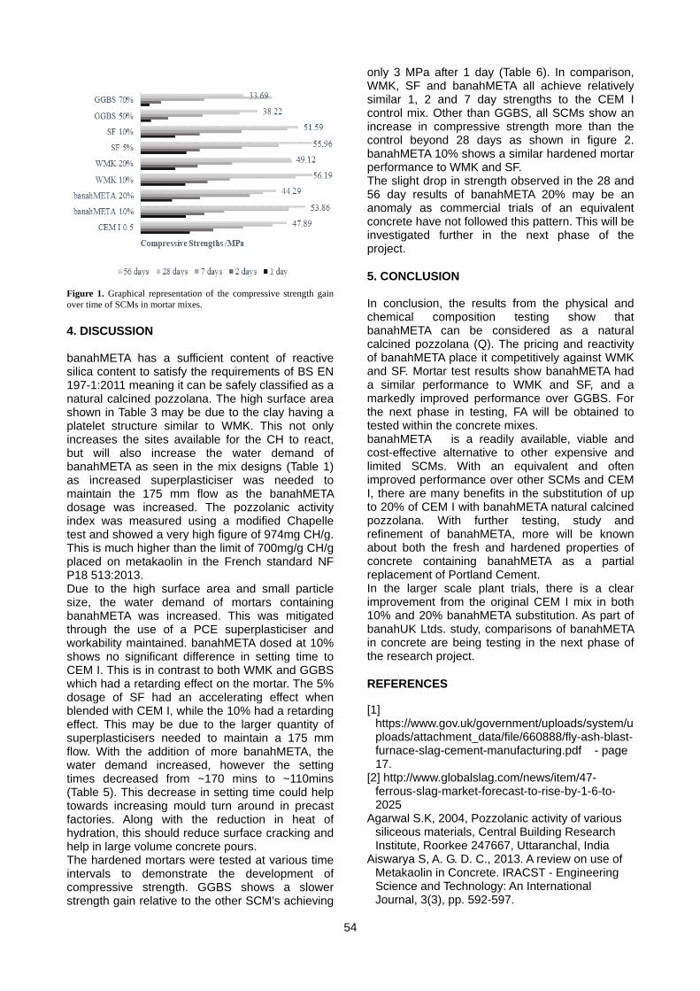
12:20 Ye, J. A bubble-based grid generation and optimisation framework for the design of free-form grid shells
Bath University Zhejiang University, China
12:30 Lunch 13:30 Whittaker, J. Material Mixology; ‘Without precedent’ in architectural education Queen University Belfast
13:40 Yliniemi, J. Alkali-activated mineral wool wastes University of Oulu, Finland Sheffield University
13:50 Kibriya, L. A bubble-based grid generation and optimisation framework for the design of free-form grid shells Imperial College London
14:00 Chaliasou, A. Concretes incorporating recycled geopolymer aggregate- Implications and properties correlations Bath University
14:10 Anike, E. Recycled Concrete Aggregate and its Prospects in Structural Concrete Coventry University
14:20 Oakes, L. A critical evaluation of the influence of the liquid to solid (L/S) ratio on the mechanical properties of novel geopolymer cements developed to create structural insulated panels
Ulster University
14:30 Muslim, F. The interface bond strength between reinforcement spacer and concrete Imperial College London 14:40 Coffee break 15:10 Gilligan E. Material imagination; a new methodology for architects and materials Queen University Belfast
15:20 Alalea Kia Examining the clogging potential of permeable concrete and development of a high strength clogging resistant system Imperial College London
15:30 Almeida, F.C.R.
Effect of aggregates on SAP performance in cementitious matrices with ground granulated blast-furnace slag
Glasgow Caledonian University
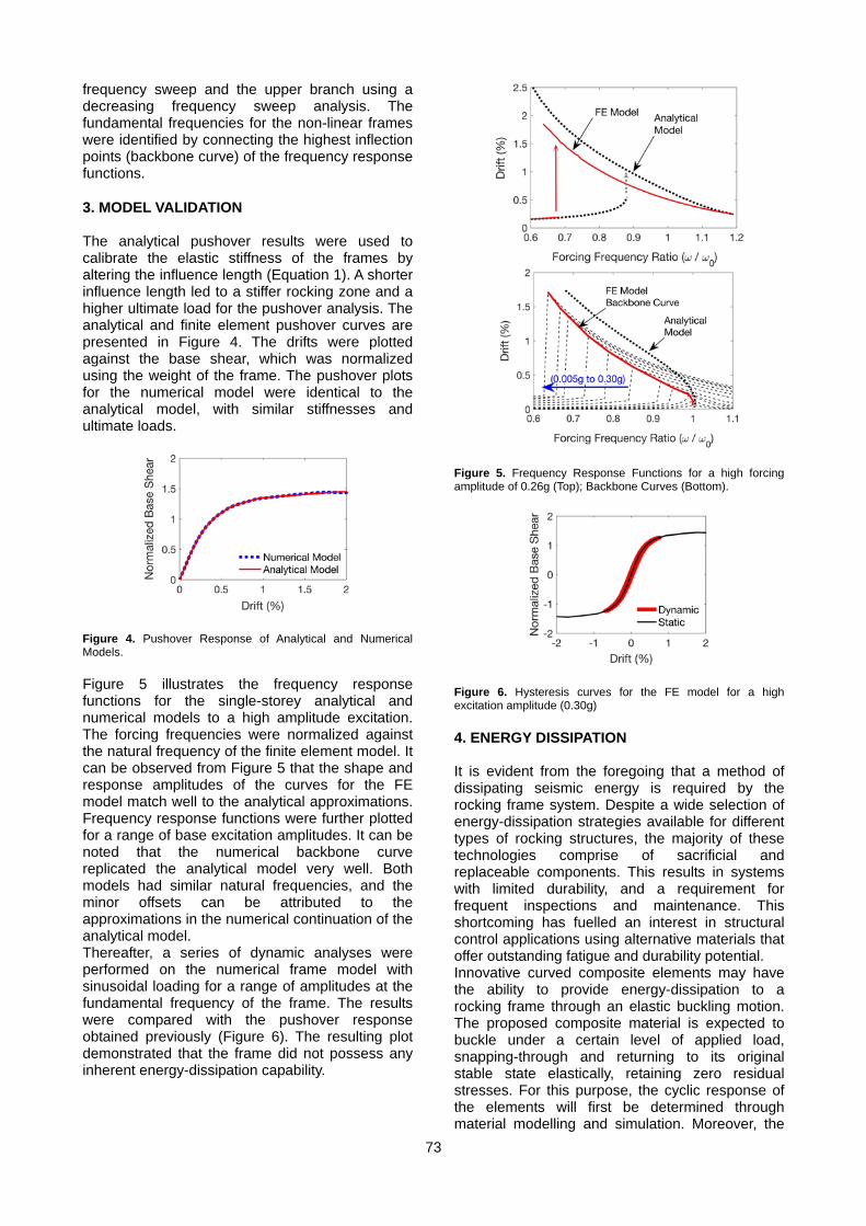
15:40 Dams, B. Cementitious mortars and polyurethane foams for additive building manufacturing Bath University 15:50 Thompson, D. Performance of Concrete Tanks in Biogenic Environments Queen University Belfast
16.00 Sayed, E. A Biomimetic Future. How can nature inspire us to reimagine materials and manufacturing?
Biohm Ltd Northumbria University
16:10 Elmslie, C. Numerical Modelling of Stainless Steel Beam Subject to Shear Northumbria University 16.20 Prizes and acknowledgements
5
Young Researchers’ Forum IV Innovation in Construction Materials 09 April 2018 Paper Number 01
On the Sustainable Development of Cement
T. Hanein, J. L. Provis, and H. Kinoshita Department of Materials Science and Engineering, The University of Sheffield, Sheffield S1 3JD, UK
ABSTRACT Cement is the most manufactured product on earth. Unfortunately, the manufacture of cement is accompanied by the emission of carbon dioxide gas. Among all manufacturing industry sectors in the UK, the cement industry is the largest CO2 emitter and these emissions are damaging our planet. The sustainable development of cement will allow future generations to develop without being compromised by the cement industry. This work identifies some of the routes to reducing the environmental burden of the cement industry. 1. INTRODUCTION Portland cement (PC) hs been used over the past century as the binder of almost all our infrastructure. Approximately four billion tons of PC is produced globally every year (Jewell and Kimball, 2015) making it the second most consumed commodity in the world; surpassed only by water. Due to the high demand for cement, its production is responsible for approximately 8% (Olivier et al., 2016) of global anthropogenic CO2 emissions that are damaging our planet. Climate change mitigation is one of the major global challenges today, and the sustainable development of the cement industry is an essential part of this. Calcium oxide is a key constituent of PC clinker phases, and is obtained from CaCO3. Approximately two thirds (by volume) of the CO2 emissions associated with traditional cement manufacture are generated from the embodied carbon liberated upon ignition of the CaCO3 sources used such as limestone; the remainder are mainly from the combustion of fossil fuels required for the pyro-processing of the raw materials. In addition to direct process efficiency improvements, several avenues have been explored to reduce the environmental carbon burden of cement manufacture including: (1) the use of supplementary cementitious materials (SCMs), (2) the adoption of alternative raw materials, (3) the use of alternative fuels, (4) carbon capture and storage, and (5) the formulation of alternative low-carbon binders. The former three have already been applied by the cement industry, as they have been relatively easy to implement. However, the scope for further improvement using alternative raw materials and SCMs is limited due to the limited availability of alternative raw materials where a significant fraction of the necessary calcium for the clinker exists in a de-carbonised form, and by the limited
availability of SCMs that require only minor or no processing (Gartner and Hirao, 2015). The use of alternative fuels has been found to mainly improve the economic performance of cement production rather than significantly reducing its negative environmental effects (Galvez-Martos and Schoenberger, 2014). Carbon capture and storage is difficult to implement at scale as it is technologically immature, will require major capital investments, and is currently uneconomical without supporting governmental regulations to incentivise its adoption. The formulation of alternative low-carbon binders is one of the most auspicious paths to reducing the CO2 emissions associated with cement manufacture. 2. ALTERNATIVE “LOW-CARBON” BINDERS The most promising and semi-established alternatives to PC are calcium sulfoaluminate (C$A) based cements and geopolymer cements. C$A cements are already produced in the world today (most notably in China) and used in both structural and non-structural applications; however, they are mainly used today for special applications. They have potential for widespread use in general construction as their manufacture offers a reduction in CO2 emissions of approximately 30% when compared to PC due to their lower energy, temperature, and limestone requirements (Hanein et al., 2018). The production of C$A-based cement at industrial scale requires minimal new capital investment as they can be produced in existing cement kiln configurations with only minor modifications (Hanein et al., 2016, Hanein et al., 2017a). C$A cements also have the advantage that cheaper high-sulfur containing fuels or “sour” fuels can be used in their pyro-processing as the sulfur will be incorporated into the clinker. Additionally, C$A cement can achieve a strength within a few days that requires 28 days for PC. The main hindrance to the production of C$A-based cements at industrial scale in Europe is the cost of
6
the additional alumina source required to form the calcium sulfoaluminate phase: ye’elimite (Hanein et al., 2018). However, the use of high alumina-containing clays and/or alumina-containing wastes or by-products instead of the more expensive bauxite mineral for the mass production of C$A-based cements are proven alternatives. The performance of geopolymer cements is equal to or better than the performance of PC in numerous applications. Producing geopolymer cements from fly ash and slag does not require pyro-processing and therefore does not produce CO2 emissions or require major capital investment. However, producing the necessary alkali activator does lead to the emission of CO2. The availability of fly ash and slag is limited in many OECD countries; therefore, in these places the long-term adoption of geopolymer cement as an alternative to PC will rely on a shift to other aluminosilicate materials such as metakaolin, which does require heat treatment for its production (de-hydroxylation of kaolin). The cost (environmental and monetary) of the required activator is a significant challenge facing larger-scale geopolymer cement deployment. However, the production of NaOH via sustainable carbon-neutral energy sources is a promising proposition for producing alkaline activators at industrial scale for geopolymer cements (Rethinking Cement, 2017). 3. DEVELOPING THE PORTLAND CEMENT PRODUCTION PROCESS PC is by far the most trusted, developed, and understood material in global construction. Modern and up-to-date PC plants boast an energy efficiency of 50 - 60% (European Commission, 2013). Some of the existing PC plants today are less efficient as they use older technologies, and updating these plants to use the best available techniques and the most efficient equipment is one direct way of reducing their fuel-derived carbon footprint. However, in many cases this may not be economical, and thus realistic, due to the residual “lifetime” of the plant’s quarry. As there is little room for inexpensive improvement in the modern PC plant configurations, a research avenue that requires substantial exploration is creating a novel low-carbon process for the manufacture of PC. Research avenues on the manufacture of PC discussed here include using electric furnaces powered from sustainable energy sources, and lowering the temperature of cement manufacture. Sustainable energy generation is undergoing rapid development; carbon-based fuels are considered to be in limited supply, and will eventually be depleted. Thus, industry should consider a shift towards using sustainable sources to power chemical processes. Using sustainable energy sources for the manufacture of cement implies the need for indirectly fired electric furnaces.
Researchers have been making cement in electric powered furnaces for decades; so, it is well known that the manufacture of PC is feasible in the absence of a combustion atmosphere. In an electric furnace, the temperature and energy required for the calcination of CaCO3 would decrease as the atmosphere would have a lower CO2 partial pressure; thus, promoting the de-carbonisation of CaCO3 (see Fig. 1). Utilising electric furnaces will also allow for easier and more economical capture and/or sequestration of CO2 as the flue gas would have a higher CO2 concentration. Another advantage of using electric furnaces for cement manufacture is the reduction of the associated NOx emissions, as excess air for combustion of fossil fuel will not be required. The use of electric kilns powered from sustainable sources should also be considered for the lime and magnesia cement industries. To develop this concept, reactive heat transfer models are necessary and a systematic study quantifying its benefits is required.
Figure 1. Thermodynamic stability of CaCO3 as a function of temperature and CO2 partial pressure calculated from data taken from McBride et al., 2002.The dashed lines represent the CO2 partial pressures in air and in a conventional PC kiln. Note that the CO2 concentration in the pre-calciner will be higher due to the CO2 evolving from calcination. The advantages of producing cement at lower temperatures include the requirement for less traditional carbon-based fuels and the capability of using alternative fuels that have lower flame temperatures. An already industrialised method to reducing the clinkering temperature of PC is the use of mineralisers such as CaF2 where the fluorine allows for the entropy stabilisation of alite (the major phase in PC clinker) at a temperature approximately 200°C lower than is traditionally used (Shame and Glasser, 1987). More recent research studies have focused on reducing the temperature of cement production even further via molten salt syntheses of cement compounds (Photiadis et al., 2011, Hanein et al., 2017b). One hurdle in producing cement via molten salt syntheses is finding a cheap localised salt source. The cheapest salts with appropriate melting temperatures are chloride salts; chloride is well known to be damaging to reinforced concrete as it promotes steel corrosion (Galan and Glasser, 2015), and so introducing more chloride into the
7
system may not be welcomed by the construction industry unless complete separation of the salt from the final product is ensured. Also, due to the energetics of alite (the major phase in PC) formation, it may not be possible to produce it at much lower temperatures than is already practiced. However, there exists the potential to produce additives to PC or other types of cement via molten salt syntheses. Modern cement pyro-processing is performed in a pre-calciner rotary kiln configuration where the calcination of limestone is followed by clinkerisation. However, if these two parts are de-coupled, advantages can be realised. Firstly, it would be easier and more economical to capture and/or sequester CO2 from the front end (where calcination occurs) if the process is de-coupled as the flue gas would have a higher CO2 concentration (no kiln combustion air). Also, other advanced process technologies can be adopted to replace part or all of the cement manufacturing process. 4. DISCUSSION The two types of alternative binders with the greatest potential to replacing PC are calcium sulfoaluminate and geopolymer cements. However, as different cements and hybrids thereof have different properties, it could be more beneficial to shift to using application-specific cements rather than looking for a “one size fits all” solution. Market uptake of alternative binders to be used in general construction applications is hindered by the availability of raw materials and, in some cases, the lack of standardisation which delays the subsequent use of these new binders by the construction industry. If the construction industry is to maintain PC as a binder for general construction, new and exciting ways of thinking are necessary to develop a novel low-carbon PC production process and mitigate the environmental burden of the cement industry. One idea is the use of electric furnaces powered from sustainable sources. The construction industry has a necessarily conservative mind-set due to the enormous quantities of materials that must be processed, and the very high consequences of technical failure of infrastructure – so they are not easily convinced to take up new technologies. Governments around the world have already implemented CO2 taxation and the cost of emitting CO2 is on the rise. Therefore, the cement industry will eventually have no choice but to act further on its environmental burden and the avenues discussed here should be considered. REFERENCES European Commission, 2013. JRC Reference
Report on Best Available Techniques in the
Cement, Lime and Magnesium Oxide Manufacturing Industries.
Galan, I., Glasser, F. P., 2015. Chloride in cement. Advances in Cement Research 27(2): 63-97.
Galvez-Martos, J.L., Schoenberger, H., 2014. An analysis of the use of life cycle assessment for waste coincineration in cement kilns. Resources, Conservation and Recycling, 86:118-131.
Gartner, E., Hirao, H., 2015. A review of alternative approaches to the reduction of CO2 emissions associated with the manufacture of the binder phase in concrete. Cement and Concrete Research, 78:126-142.
Hanein, T., Galan, I., Elhoweris, A., Khare, S., Skalamprinos, S., Jen, G., Whittaker, M., Imbabi, M. S., Glasser, F. P., and Bannerman, M. N., 2016. Production of Belite Calcium SulfoAluminate cement using sulfur as a fuel and as a source of clinker sulfur trioxide: Pilot kiln trial. Advances in Cement Research, 28(10):643-653.
Hanein, T., Galan, I., Glasser, F. P., Skalamprinos, S., Elhoweris, A., Imbabi, M. S., and Bannerman, M. N., 2017a. Stability of ternesite and the production at scale of ternesite-based clinkers. Cement and Concrete Research, 98C: 91–100.
Hanein, T., Provis, J.L., Nyberg, M., Quintero Mora, N. I., Tyrer, M., Maries, A., Kinoshita, H., 2017b. Molten salt synthesis of compounds related to cement. 1st International Conference on Cement and Concrete Technology, Muscat, Oman.
Hanein, T., Galvez-Martos, J. L., Bannerman, M. N., 2018. Carbon footprint of calcium sulfoaluminate clinker production. Journal of Cleaner Production, 172:2278-2287.
Jewell, S., Kimball, S.M., 2015. Mineral Commodity Summaries. US Department of the Interior: US Geological Survey.
McBride, B.J., Zehe, M.J., Gordon, S., 2002. NASA Glenn Coefficients for Calculating Thermodynamic Properties of Individual Species. NASA TP-2002-211556.
Olivier, J.G.J., Janssens-Maenhout, G., Muntean, M., Peters, J.A.H.W., 2016. Trends in Global CO2 Emissions: 2016 Report. PBL NEAA and ECJRC IES.
Photiadis, G. M., Maries, A., Tyrer, M., Inman, D., Bensted, J., Simons, S., Barnes, P., 2011. Low energy synthesis of cement compounds in molten salt. Advances in Applied Ceramics 110(3): 137-141.
Rethinking Cement. Beyond Zero Emissions Technical Report. Available at: http://bze.org.au/rethinking-cement-plan/.
Shame, E.G., Glasser, F.P., 1987. Stable Ca3SiO5 solid solutions contaning fluorine and aluminium made between 1050 and 1250°C. Transactions and Journal of the British Ceramic Society 86(1): 13-17.
Young Researchers’ Forum IV Innovation in Construction Materials 09 April 2018 Paper Number 02
The Mechanical and Durability properties of pervious concrete
utilizing construction and demolition waste with varying aggregate sizes.
Reid B., Tilling J., Nagaratnam B.a, Richardson A., Poologanathan K.
Department of Mechanical and Construction Engineering, Northumbria University , Newcastle Upon Tyne, United Kingdom
acorresponding author’s email: [email protected] ABSTRACT Pervious concrete is a type of porous concrete that has an open graded structure with interconnected voids. This type of concrete allows water to flow through the body of the concrete, this results in less liquid standing on the road, resulting in better grip on the surface. It is extremely beneficial for road and pavement surfaces, as it ensures better road safety due to the increased surface friction. In addition, it is also advantageous in drainage systems within urban areas causing lesser amounts of surface runoff during heavy precipitation. This quality of pervious concrete can aid in reducing flood risk, as, the amount of surface runoff in these locations will decrease and consequently water will spread more evenly. Subsequently, construction and demolition (CDW) waste accounts to a major portion of waste generated in the EU, with most of it buried in landfills. Research suggests that this type of waste is suitable for pavement application. However, there is still a lack of research in the application of construction and demolition waste in pervious concrete. In this research, the mechanical properties of pervious concrete were measured for compressive and splitting tensile strength. The pervious concrete was batched with construction and demolition waste, with varying aggregate sizes and percentage of replacement of virgin aggregate. The results show that the aggregates from this type of waste; especially smaller size aggregates are suitable for use in pervious concrete, hence, providing a sustainable solution for pavements.
10
1. INTRODUCTION The construction industry produces vast amount of construction and demolition waste (CDW) every year. Much of this waste usually finds its way to landfill where it can be ‘forgotten about’ (Silva, de Brito and Dhir, 2014). The industry then continues to build using mined and quarried aggregates and other construction materials, forgetting that these are a finite resource. According to (de Magalhães, Danilevicz and Saurin, 2017) the construction industries largest environmental impact derives from the generation of CDW. A good way to help reduce this issue is to use the waste materials for new applications, such as aggregate replacement in concrete. There have been numerous studies on the use of waste material as an aggregate replacement, they concluded that waste aggregates have a higher permeability and porosity when compared to natural aggregates (Zaetang et al., 2016). Theoretically CDW aggregates would be perfect for pervious concrete. Pervious concrete has seen use in sustainable urban drainages developments due to its ability to allow water to pass through it, discharging storm water runoff into the ground helping recharge water levels. There is currently a lack of understanding with utilizing CDW in pervious concrete. Further research could help produce a material which is comparable to new pervious concrete while also reducing the environmental impact attributed to the construction industry. The following authors (de Magalhães et al., (2017). Silva et al., (2014). Shahidan et al., (2016) have previously carried out research into pervious concrete utilizing construction and demolition waste. However, it was found that those research was lacking in the use of varying CDW aggregate sizes, and the effects this would have on the concrete properties. Due to the lack of research for pervious concrete utilizing waste materials, it is important that both the mechanical and durability properties of this material are known for varying aggregate sizes. Previous research has identified what the addition of waste material has on pervious concrete. However, it did not look at what effect varying sizes of waste aggregate would have on the pervious concrete and whether an efficient mix can be found. If these properties are known, then an application for pervious concrete utilizing waste material can be found. 2. EXPERIMENTAL PROGRAMME 2.1 Materials The pervious concrete requires three main materials for its manufacture, CEM 1 Portland cement, coarse aggregates and water. A superplasticizer was used to help reduce the w/c
ratio that was added with potable tap water for the mixing. Mixed samples were cured at a temperature of 20 degrees. This study required two types of coarse aggregate, a 20mm graded natural aggregate and a 10mm single sized recycled aggregate which was collected from Thompsons of Prudhoe at the Springwell quarry. The recycled aggregate consisted of approximately 70% concrete waste, 20% brick waste, 5% bitumen waste and 5% anomalous waste. Each of the waste materials underwent no treatment, leaving the adhered cement paste to the concrete waste material. This helps to reduce production costs of the pervious concrete and the adhered cement paste can reactivate when in contact with water. Therefore, reducing the amount of cement to the mix. 2.2 Mixture proportions and procedures A total of 3 mix proportions were designed for the pervious concrete, which can be seen in Table 1. A control mix was designed using 100% NA. The remaining mixes contained a 50% RA replacement and another 100% RA replacement. For all three of the mixes, the cement, water, superplasticizer and aggregate amounts were kept constant. The mixing process was carried out using a rotating drum mixer. The 100% NA and 50% RA replacement mixes were dry mixed for 3 min, the 100% RA mix didn’t require mixing due to it being single sized 10mm aggregate. This was followed by an additional 3 min dry mixing when the CEM 1 cement was added. Once mixed well, both the water and superplasticizer were added together slowly for a further 3 min mixing. The consistency of the mixture was checked using the ball-in-hand consistency test following the requirements of ASTM C860. The test was carried out as a rudimentary check to see whether additional water or superplasticiser was required. A slump test, conforming to BS EN 12350-2:2009, was carried out for each of the mixture proportions. The 100% NA mix had a slump of 0mm, the 50% RA mix had a slump of 13mm and the 100% RA mix had a slump of 15 mm. This helped confirm that pervious concrete has a low workability. Finally, the fresh concrete was poured and finished in 45 (15 100% NA, 15 50% RA, 15 100% RA) cube moulds and 12 (4 100% NA, 4 50% RA, 4 100% RA) cylinder moulds. The concrete was poured in thirds and tamped using a tamping rod after each third was poured. A towel was used to finish off the moulds. All specimens were demoulded after 72 hours. The demoulded specimens were left to cure in water until the age of testing.
11
Table 1. Mix Proportions Mix design
Cement (kg)
Water (ml)
SP (ml)
Coarse aggregates NA (kg)
RA (kg)
100% NA
8 2000 60 36.4 0
50% RA
8 2000 60 18.4 18.4
100% RA
8 2 60 0 36.4
2.3. Testing It should be noted that the mechanical properties will be carried out after 28 days and durability will be carried out on 3 days for the pulse velocity and 60 days for the Freeze/Thaw after casting. Mechanical Properties:
• Compressive strength – According to (Zaetang et al., 2016), the strength of pervious concrete is one of the most important parameters so recycled aggregates should be able to prove some form of strength in the concrete. This test will be used to determine the maximum compressive strength for each of the sample cubes with differing percentage waste replacements and varying aggregate sizes influencing the maximum compressive strength. It will be carried out according to BS 1881-116.1983.
• Tensile Splitting – Each mix proportion will be tested for tensile splitting test using 100⌀ x 200mm cylinders according to BS EN 2390-6:2009.
Durability Properties: • Permeability – The permeability of each
sample was determined using the falling head method. The specimens used were 100 x 100 x 100mm cubes. Each cube had all four sides covered in a 1:1 cementitious grout with a silicone coating added to the grout once cured. This ensured a uniaxial water infiltration in the vertical direction through each sample. The test required the time to be taken for 225mm head of water to fully flow through the sample. The parameters were kept the same for each sample to help mitigate any anomalous results. The test was carried out using a non-standardised method for falling head permeability.
• Freeze Thaw – The 100⌀ x 200mm cylinders will be subject to 56 freeze/thaw cycles carried out over 28 days. The Freeze/Thaw process is based upon ASTM666 and BS15177.
3. RESULTS AND DISCUSSION
3.1. Mechanical Properties 3.1.1. Compressive Strength Figure 2 shows the ultimate compressive strength for all mixes, including the mixes used for permeability and Freeze/Thaw testing. The highest compressive strength of 8.79MPa was identified in the 28 days cured batch. NA having the highest compressive strength continues for the permeability tested cubes at 5.58MPa and the Freeze/Thaw cubes at 3.37MPa. Meanwhile for the RA replacement mixes, the addition of recycled aggregate has reduced the compressive strength over the three tested batches. However, the reduction in strength is not as drastic when compared to previous studies. Yap et al., (2018) identified that a pervious concrete mix with 100% RA replacement would have a 50% strength reduction compared to 100% NA. A potential reason why the 50% RA mix didn’t have a 50% compressive strength reduction could be due to the size of the aggregates used in the mix. A 10mm single sized aggregate mixed with a 20mm graded aggregate. It was expected that the permeability tested cubes should produce the same results as the 28 days cured. However, the results show that the 100% NA, 50% RA replacement and 100% RA mixes were between 40-50% weaker than the 28 days cured mixes. This can be explained due to the possibility of thermal cracking. The only difference in preparation was that the permeability tested cubes had to be oven dried at 105°C which had the potential of introducing thermal cracks to each specimen. The Freeze/Thaw specimens were also heated at 105°C, but due to the Freeze/Thaw cycle, the samples had a 40-50% reduction in compressive strength compared to the permeability tested samples.
Figure 2. Ultimate compressive strengths for all mixes. 3.1.2. Tensile Splitting Figure 3 shows that tensile splitting strength for all mixes. The tested samples were all 28 days cured and had not been subjected to oven drying or Freeze/Thawing. 100% NA samples produced the highest tensile splitting strengths at 1.54 MPa. Like the compressive strength results, the tensile
12
strength does not fully follow what previous research has shown. Increasing percentage replacements for recycled aggregate should reduce the tensile splitting strength. However, from Figure 2 this statement is correct for both the 100%NA and 100% RA samples but not for the 50% RA replacement samples. The 50% replacement sample is seen to be approximately 30% weaker than the 100% NA and 10% weaker than the 100% RA replacement. One explanation for this could be due to irregularities during the casting process. Figure 4 indicates that there were areas in the cylinders where 10mm recycled and 20mm natural aggregate had clumped together. Therefore, producing a non-homogeneous mix leading to reduced strength.
Figure 3. Tensile splitting strength for each mix proportion. 3.2. Durability Properties 3.2.1. Permeability The porous nature of permeable concrete allows water to pass through it. This enables pervious concrete to stand out from normal concrete which is designed to prevent water intrusion. Therefore, water permeability is just as important as concrete strength characteristics. Both the 50% and 100% RA replacement pervious concrete mixes achieved a good physical appearance due to the inclusion of smaller aggregate. The 100% NA pervious concrete mix is less aesthetically pleasing due to the large 20mm rounded aggregate and visual presence of large pores. Yap et al., (2018) identified that pervious concrete with permeability values ranging between 0.1 and 3.3 cm/s are adequate to be used as a drainage layer for pavements. The range of permeability coefficients for all three mixes were between 1.91 and 2.56 cm/s. Therefore, all three mix proportions can be used for the mentioned application. Figure 4 indicates that both 100% Na and 50% RA replacements have close to identical permeability coefficients. In addition, Yap et al.,(2018) found that increasing the recycled replacement aggregate past 50% starts to drastically increase the permeability coefficient of the pervious concrete. The values in Figure 4 support this, the 100% RA replacement has a 25% increase in permeability.
Figure 4. Permeability coefficients for each mix proportion (permeability and Freeze/Thaw mixes). 4. CONCLUSION It can be concluded that the use of multiple sized aggregates in a 50/50 mix, 20mm rounded course natural aggregate and 10mm recycled course aggregate, produce similar strength and permeability characteristics as 100% NA mixes. With the mix meeting the standard for drainage systems, this opens the option of utilizing construction and demolition waste for 50% of aggregate replacements. 100% RA replacement can still be used in design but only in specialized situations where applied loading is low. The materials in this paper require further testing before it can be determined to be a fully usable material e.g. abrasion resistance, filtration effects, skid resistance and an environmental assessment on the use of this recycled material. REFERENCES Barnhouse, P. and Srubar, W. (2016). Material
characterization and hydraulic conductivity modeling of macroporous recycled-aggregate pervious concrete. Construction and Building Materials, 110, pp.89-97.
berry, suozzo, Anderson and Dewoolkar (n.d.). Properties of Pervious Concrete Incorporating Recycled Concrete Aggregate. Using Recycled Concrete in Pervious Concrete Pavements.
de Magalhães, R., Danilevicz, Â. and Saurin, T. (2017). Reducing construction waste: A study of urban infrastructure projects. Waste Management, 67, pp.265-277 Richardson, A., Coventry, K. and Bacon, J. (2011).
Freeze/thaw durability of concrete with recycled demolition aggregate compared to virgin aggregate concrete. Journal of Cleaner Production, 19(2-3), pp.272-277.
Shahidan, S., Azmi, M., Kupusamy, K., Zuki, S. and Ali, N. (2017). Utilizing Construction and Demolition (C&D) Waste as Recycled Aggregates (RA) in Concrete. Procedia Engineering, 174, pp.1028-1035.
13
Silva, R., de Brito, J. and Dhir, R. (2014). Properties and composition of recycled aggregates from construction and demolition waste suitable for concrete production. Construction and Building Materials, 65, pp.201-217.
Sindhu and Rajagopal, D. (2015). Experimental Investigation on Maximum Strength of Pervious Concrete Using Different Size of Aggregates.
Wu, H., Liu, Z., Sun, B. and Yin, J. (2016). Experimental investigation on freeze–thaw durability of Portland cement pervious concrete (PCPC). Construction and Building Materials, 117, pp.63-71.
Yap, S., Chen, P., Goh, Y., Ibrahim, H., Mo, K. and Yuen, C. (2018). Characterization of pervious concrete with blended natural aggregate and recycled concrete aggregates. Journal of Cleaner Production, 181, pp.155-165.
Zaetang, Y., Sata, V., Wongsa, A. and Chindaprasirt, P. (2016). Properties of pervious concrete containing recycled concrete block aggregate and recycled concrete aggregate. Construction and Building Materials, 111, pp.15-21.
14
15
Young Researchers’ Forum IV Innovation in Construction Materials 09 April 2018 Paper Number 03
Performance of CLT Wall Systems and Typical CLT Wall Panel to CLT Floor Panel Connections under Monotonic Loading
C. Hughes, D. McPolin and P. McGetrick
Department of Civil Engineering, Queen’s University Belfast
D. McCrum Department of Civil Engineering, University College Dublin
ABSTRACT Despite the construction of cross-laminated timber (CLT) buildings up to 10 storeys in areas of low seismicity, few multi-storey CLT buildings have been constructed in areas of moderate to high seismicity due to lack of knowledge regarding the seismic performance of the material. Consequently, further research is required to provide the experimental basis necessary to develop such knowledge so that CLT becomes a competitive construction material for use in mid-rise and high-rise buildings in seismically active regions. This study aims to further the understanding of the behaviour of wall systems within multi-storey CLT buildings under lateral loading by experimentally testing wall systems representative of those found within a 10 storey CLT building. Additionally, typical connections found within multi-storey CLT buildings are tested under monotonic loading to assess their performance and influence on the behaviour of entire CLT wall systems. 1. INTRODUCTION In response to the global drive towards sustainable construction, cross-laminated timber (CLT) has emerged as a competitive alternative to other construction materials due to its sustainable attributes. Cross-laminated timber is an engineered wood product formed from layers of timber boards bonded to each other orthogonally, to create large two-way spanning structural panels which can be used to form walls, floors and roofs of buildings. CLT panels are typically connected using metal connectors including hold downs which resist uplift of the walls, angle brackets which resist sliding of the walls and screwed connections which resist shear between adjacent and orthogonal panels. It is a prefabricated material which results in reduced on-site construction times, reduced material wastage and therefore reduced costs. Due to its high strength-to-weight ratio, it is fast becoming the solution to constructing high density housing on inner-city sites where underground infrastructure limits foundation loads. While large scale production of CLT was established in Europe in the early 2000s, Structurlam and Nordic Structures in Canada became the first North American manufacturers of CLT more recently in 2010 (Pei et al., 2016a); as a result, the majority of tall CLT buildings have been constructed in Europe. Hackney, London, is one of several local authorities across the world encouraging engineers and architects to consider timber before other construction materials. This
has led to the construction of some of the world’s tallest CLT buildings, such as Stadthaus and Bridport House, in Hackney. Dalston Lane, a 10 storey residential building located in Hackney is currently the world’s tallest CLT building having been completed in 2017 (Harley et al., 2016). While CLT buildings up to 10 storeys are being constructed, and taller buildings are currently being considered, few CLT buildings have been constructed in areas of moderate to high seismicity (Pei et al., 2016b). Timber is a commonly used material in seismically active regions due to its high strength-to-weight ratio, and the ductility and high energy dissipation capability of its connection systems. However, CLT has not been adopted as a construction material in areas of moderate to high seismicity due to lack of knowledge regarding the seismic performance of CLT buildings and lack of structural codes for the material. Therefore, further research is required to provide the experimental basis necessary to develop such knowledge and so that CLT becomes a competitive construction material for use in mid-rise and high-rise construction in seismically active regions. 2. BACKGROUND Previous research into the seismic behaviour of CLT buildings has involved experimental investigations to evaluate the overall behaviour of CLT wall systems under monotonic and cyclic loading (Dujic et al., 2004; Ceccotti et al., 2006; Popovski et al., 2010; Gavric et al., 2015). The previous experimental studies have been limited to replicating the conditions within multi-storey
16
buildings with approximately three storeys. The maximum vertical loading and panel thickness used were comparable to ground floor wall systems within a full-scale three storey CLT building tested as part of the SOFIE project (Ceccotti, 2008). Thus, to develop sufficient understanding of how CLT wall systems in high-rise buildings will behave when subjected to lateral loading, testing of configurations reflecting the conditions of CLT wall systems in taller buildings need to be undertaken. The behaviour of CLT wall systems can be assessed by observing the global deformation of the wall system when a lateral load is applied. As suggested by Gavric el al. (2015), the deformation mechanisms which may be observed include sliding and rocking of the wall, as well as shear and bending deformations of the wall panel itself. Gavric et al. (2015) have suggested that wall panel deformations are negligible, with sliding and rocking the predominant deformation mechanisms which are controlled by the response of the connections. Therefore, the behaviour of each connection within a wall system must be fully understood in order to predict the global behaviour of a CLT wall system. There has been limited research on performance assessment of CLT wall systems in above ground floor storeys. In most wall configurations tested, the CLT wall panels are anchored to steel or concrete foundations; very limited information has been published about configurations tested in which the CLT wall panels are fixed to CLT floor panels, as typically found in above ground floor storeys. As tall buildings would have large numbers of CLT wall panel to CLT floor panel connections, the behaviour of these connections must be further investigated in order to evaluate the behaviour of wall systems in above ground floor storeys, and therefore the overall performance of tall CLT buildings. The purpose of this research is to further the understanding of the behaviour of wall systems in multi-storey CLT buildings under lateral loading. Experimental tests are being undertaken to evaluate the global behaviour of above ground floor CLT wall systems, representative of those found within a 10 storey CLT building, under monotonic loading. These tests will allow the variation in global behaviour of wall systems at each storey within a multi-storey CLT building to be evaluated. Additionally, the behaviour of typical CLT wall panel to CLT floor panel connections under monotonic loading in both shear and tension will be experimentally investigated to assess each connection’s individual performance and therefore influence on the global behaviour of the entire wall system. 3. TESTING OF CLT WALL SYSTEMS UNDER MONOTONIC LATERAL LOADING
Test Setup A series of eight tests were undertaken on a CLT wall system. During each test a vertical load was applied and maintained, with each vertical load representative of the gravity load experienced by the walls at various storeys within a 10 storey CLT building. While the vertical load was maintained, the wall was loaded laterally in increments of 5kN to a maximum load of 50kN. The maximum lateral load of 50kN was selected to ensure the connections behaved elastically. As this study focuses on CLT wall panel to CLT floor panel connections, the ground storey wall system in which the wall panel is fixed to a concrete foundation was not investigated, nor was the top storey in which vertical load is relatively small; thus, the vertical loads were representative of the gravity loads in floors 2-9 of a 10 storey CLT building. The vertical and lateral loads applied in each test are summarised in Table 1. Table 1. Test loads
Test
Floor Vertical Load (kN/m)
Maximum Lateral Load (kN)
T1 2 84.0 50
T2 3 73.5 50
T3 4 63.0 50
T4 5 52.5 50
T5 6 42.0 50
T6 7 31.5 50
T7 8 21.0 50
T8 9 10.5 50
Due to the limited clear space under the frame of the vertical actuator the height of the wall panels tested was 1.5m, approximately half of the typical height of walls in CLT buildings. The wall panels had a width of 2.95m. The CLT panels used were 100mm thick. Typical CLT connectors were used to fix the wall panel to the floor panel; the wall panel was anchored to the floor panel using two WHT340 hold downs partially nailed with twelve 4x60mm anker annular ring nails and eight ABR105-R angle brackets with sixteen 4x60mm anker annular ring nails. The floor panel was rigidly fixed to the floor of the laboratory. The test set up is show in Figure 1.
17
Figure 1. Test setup
Figure 2. Displacement measurement locations To evaluate the global deformation of the wall system, displacements were measured at seventeen locations within the wall system using displacement transducers. These measurements allowed the deformation mechanisms contributing to the overall displacements to be assessed. The locations of the displacement measurements are summarised in Figure 2 and Table 2. Table 2. Displacement measurement locations
Location Measurement 1 Uplift of left hand side of wall panel 2 Uplift of right hand side of wall panel 3 Uplift of wall at AB1 4 Uplift of wall at AB2 5 Uplift of wall at AB3 6 Uplift of wall at AB4 7 Uplift of wall at AB5 8 Uplift of wall at AB6 9 Uplift of wall at AB7
10 Uplift of wall at AB8 11 Lateral displacement of floor 12 Lateral displacement of wall 13 Lateral disp. of wall 300mm from floor 14 Lateral disp. of wall 600mm from floor
15 Lateral disp. of wall 900mm from floor 16 Lateral disp. of wall 1200mm from floor 17 Total lateral displacement at top of wall
Results The data from the eight tests was analysed to assess the effect of increasing vertical load on the global behaviour of the wall system, allowing the global behaviour of the wall systems at each storey within a 10 storey CLT building to be inferred. The global behaviour can be summarised by the total vertical and lateral displacement of the wall panel and the relationship between the vertical load applied and the total lateral displacement and uplift of the wall is shown in Figure 3.
Figure 3. Vertical load (kN/m) vs. total lateral displacement/sliding displacement/uplift when lateral load is 50kN Despite no yielding of the connections during the testing, Figure 3 shows a non-linear relationship between both vertical load and total lateral displacement, and vertical load and uplift. Therefore, it is expected that there would be differing global behaviour of wall systems at each storey within a multi-storey building, with the
18
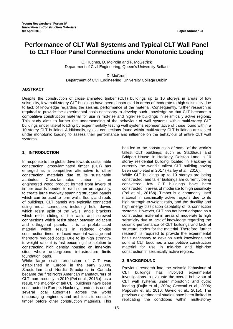
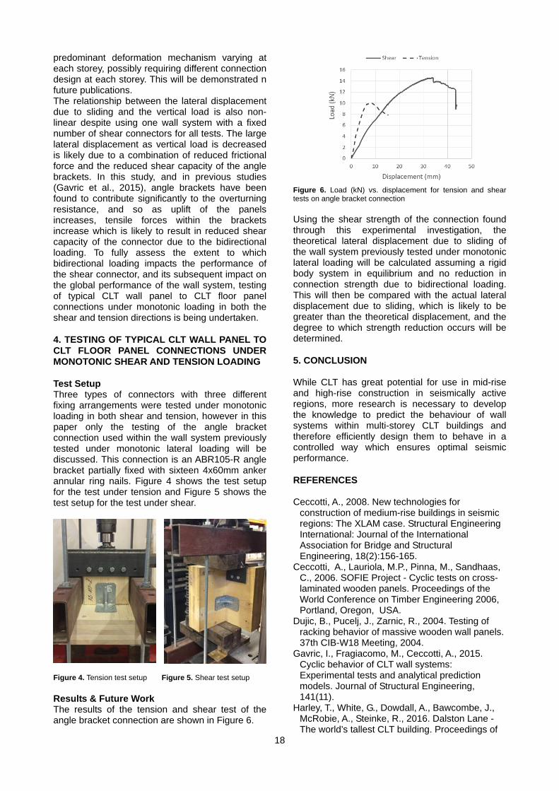
predominant deformation mechanism varying at each storey, possibly requiring different connection design at each storey. This will be demonstrated n future publications. The relationship between the lateral displacement due to sliding and the vertical load is also non-linear despite using one wall system with a fixed number of shear connectors for all tests. The large lateral displacement as vertical load is decreased is likely due to a combination of reduced frictional force and the reduced shear capacity of the angle brackets. In this study, and in previous studies (Gavric et al., 2015), angle brackets have been found to contribute significantly to the overturning resistance, and so as uplift of the panels increases, tensile forces within the brackets increase which is likely to result in reduced shear capacity of the connector due to the bidirectional loading. To fully assess the extent to which bidirectional loading impacts the performance of the shear connector, and its subsequent impact on the global performance of the wall system, testing of typical CLT wall panel to CLT floor panel connections under monotonic loading in both the shear and tension directions is being undertaken. 4. TESTING OF TYPICAL CLT WALL PANEL TO CLT FLOOR PANEL CONNECTIONS UNDER MONOTONIC SHEAR AND TENSION LOADING Test Setup Three types of connectors with three different fixing arrangements were tested under monotonic loading in both shear and tension, however in this paper only the testing of the angle bracket connection used within the wall system previously tested under monotonic lateral loading will be discussed. This connection is an ABR105-R angle bracket partially fixed with sixteen 4x60mm anker annular ring nails. Figure 4 shows the test setup for the test under tension and Figure 5 shows the test setup for the test under shear. Figure 4. Tension test setup Figure 5. Shear test setup Results & Future Work The results of the tension and shear test of the angle bracket connection are shown in Figure 6.
Figure 6. Load (kN) vs. displacement for tension and shear tests on angle bracket connection Using the shear strength of the connection found through this experimental investigation, the theoretical lateral displacement due to sliding of the wall system previously tested under monotonic lateral loading will be calculated assuming a rigid body system in equilibrium and no reduction in connection strength due to bidirectional loading. This will then be compared with the actual lateral displacement due to sliding, which is likely to be greater than the theoretical displacement, and the degree to which strength reduction occurs will be determined. 5. CONCLUSION While CLT has great potential for use in mid-rise and high-rise construction in seismically active regions, more research is necessary to develop the knowledge to predict the behaviour of wall systems within multi-storey CLT buildings and therefore efficiently design them to behave in a controlled way which ensures optimal seismic performance. REFERENCES Ceccotti, A., 2008. New technologies for
construction of medium-rise buildings in seismic regions: The XLAM case. Structural Engineering International: Journal of the International Association for Bridge and Structural Engineering, 18(2):156-165.
Ceccotti, A., Lauriola, M.P., Pinna, M., Sandhaas, C., 2006. SOFIE Project - Cyclic tests on cross-laminated wooden panels. Proceedings of the World Conference on Timber Engineering 2006, Portland, Oregon, USA.
Dujic, B., Pucelj, J., Zarnic, R., 2004. Testing of racking behavior of massive wooden wall panels. 37th CIB-W18 Meeting, 2004.
Gavric, I., Fragiacomo, M., Ceccotti, A., 2015. Cyclic behavior of CLT wall systems: Experimental tests and analytical prediction models. Journal of Structural Engineering, 141(11).
Harley, T., White, G., Dowdall, A., Bawcombe, J., McRobie, A., Steinke, R., 2016. Dalston Lane - The world’s tallest CLT building. Proceedings of
19
the World Conference on Timber Engineering 2016, Vienna, Austria.
Pei, S., Rammer, D., Popovski, M., Williamson, T., Line, P., van de Lindt, J. W., 2016a. An overview of CLT research and implementation in North America. Proceedings of the World Conference on Timber Engineering 2016, Vienna, Austria.
Pei, S., van de Lindt, J. W., Popovski, M., Berman, J. W., Dolan, J. D., Ricles, J., Sause, R., Blomgren, H., Rammer, D. R., 2016b. Cross-laminated timber for seismic regions: Progress and challenges for research and implementation. Journal of Structural Engineering, 142(4).
Popovski, M., Schneider, J., Schweinsteiger, M., 2010. Lateral load resistance of cross-laminated wood panels. In: Proceedings of the World Conference on Timber Engineering 2010, Trentino, Italy.
20
21
Young Researchers’ Forum IV Innovation in Construction Materials 09 April 2018 Paper Number 04
BOND STRENGTH BEHAVIOUR OF ZINC RICH PAINT COATING ON CONCRETE SURFACE
A. Goyal and E. Ganjian
Built & Natural Environment Research Centre, Coventry University
H.S. Pouya School of Energy, Construction and Environment, Coventry University
ABSTRACT Durability issues associated with concrete structures are the major problems the civil engineering community is facing today around the world. Concrete can suffer chemical damage from contaminants added during manufacturing and/or by action of external aggressive agents such as chlorides, carbon dioxide and moisture. Deterioration can occur in different ways in concrete like sulphate attack, alkali silica reaction, efflorescence and corrosion of reinforcing steel. Application of surface coatings and treatment on concrete surface provides a cost-effective and relatively simple approach for protecting reinforced concrete and is recommended by BS 1504-9:2008. However, they are more beneficial if corrosion is due to carbonation. Moreover, these coatings have low adhesion strength and is one of the main reason for its failure. This research aims on application of Zinc Rich Paint (ZRP) as a concrete coating and focuses on its pull-off strength behaviour for different quality concrete mix designs and under the influence of different factors such as variable concrete substrate roughness, amount of compaction and different environmental conditions. Both failure load and failure mode were recorded and observed. Medium surface roughness showed highest pull-off strength between coating and substrate i.e. 3.35 MPa which is greater than the required value of 1.5 MPa (for flexible systems with trafficking) and 2.0 MPa (for rigid systems with trafficking) recommended by BS EN 1504-2:2004. Alternatively, ZRP coatings may also provide some corrosion protection to reinforcement and the same is under study. 1. INTRODUCTION Durability issues associated with concrete structures are some of the biggest problems the civil engineering community is facing today around the world. One of the most significant durability issues is the corrosion of steel reinforcement, which leads to rust formation, cracking, spalling, delamination and degradation of structures. This is considered to be the main factor causing damage in bridges and other infrastructure (Popov, 2015 and Michel et al., 2016). Therefore, to deal with these issues, research around the globe is oriented towards developing methods or materials to prevent this corrosion of steel in concrete. Due to the increasing demand for longer service lives for infrastructure and the high cost involved in building and maintaining it, the repair of concrete structures has become extremely important (Glass and Buenfeld, 2000). The repair and protection techniques for concrete are based on chemical, electrochemical or physical principles (BSI, 2008). Since corrosion is an electrochemical process, its main components are the cathode, the anode and the electrolyte (in form of concrete pore water). The absence of any of these three components can restrict the corrosion process. Protection and repair methods which apply these principles and
suggested by BS 1504-9:2008 are: removal of delaminated/spalled concrete and replacement with new alkaline concrete and also patching, coatings, impregnation, use of corrosion inhibitors, cathodic protection, electrochemical realkalisation and electrochemical chloride removal. Choice of adopted strategy depends upon type, cause and extent of defects, whole life cost and future service conditions. The application of surface coatings and treatment on a reinforced concrete surface provides a cost-effective and relatively simple approach for protection. The main objective of surface treatment is to provide a barrier between concrete surface and environment, thus make it less permeable to ingress of aggressive substances and moisture and also increasing the concrete resistivity (Bertolini et al., 2004). Hence, sometimes they are also referred as sealers. They can be divided into 3 classes: organic coatings, hydrophobic impregnation, and cementitious coatings (Bertolini et al., 2004). Organic coatings can be dense or vapour permeable coatings. Dense coatings are based on epoxy, polyurethane or chlorinated rubber polymer and do not allow the moisture inside concrete at time of application to evaporate, which may lead to a loss of adhesion and hence coating failure (Bertolini et al., 2004). Vapour permeable coatings are generally acrylates. In case of carbonation,
22
they will not remove already present contamination, but prevent further ingress of carbon dioxide. In case of heavily contaminated concrete, the coating may fail due to the formation of salt crystals (Lambert, 2010). Hydrophobic Impregnation materials include silanes, siloxanes and silicate-based compounds. They are not effective against standing water and are most suitable on vertical surfaces where the water can run off (Lambert, 2010). They are most beneficial if corrosion is due to carbonation (Bertolini et al., 2004). These coatings have low adhesion strength and is one of the main reason for its failure. This research aims on application of Zinc Rich Paint (ZRP) as a concrete surface coating. Zinc-rich paints (ZRPs) are widely used as an anticorrosion paint on ferrous substrates, an alternative to hot-dip galvanizing (HDG) and as an under coat or top coat (Marchebois, 2004 and Hammouda, 2011). It is also used as a touch-up coat on galvanized steel to provide corrosion protection of steel in aggressive environment like seawater, marine and industrial environments (Marchebois, 2004 and Hammouda, 2011). The purpose of the current study is to study the ZRP-concrete bond mechanism for different quality concrete mix designs and under the influence of different factors such as variable concrete substrate roughness, amount of compaction and different environmental conditions. The result of this study will provide the basis for assessing the high initial bond strength and surface preparation required to use ZRP as concrete coating and anode for cathodic protection for corrosion protection of steel in concrete. 2. EXPERIMENTAL DESIGN Concrete cubes of 150×150×150 mm were cast during the study. Two different quality mixes were selected: good (water/cement ratio of 0.5, slump= 10) and poor (w/c= 0.8, slump= 20). The mix proportioning is tabulated in Table 1. Specimens were demoulded after 24 hours and cured for total period of 28 days then, allowed to age (dry in air) for at least a month prior to coating and pull-off tested as suggested by CIRIA technical note 139 and ASTM 1583 (CIRIA, 1993, ASTM, 2012). Each prepared substrate was coated with a total of 3 no. of ZRP coats to achieve a total theoretical dry film thickness (DFT) between approximately 200-350μm. Each coat of paint was applied after allowing the previous coat to dry for 24 hours. Table 1. Details of mix design of concrete
Specimens were tested for different factors:
a) Amount of compaction: Specimens were tested under 2 modes of vibration i.e. shock table mode of vibration, 8g (G1-G5 and P1-P5) and low vibration, 4-7g (G6-G7, P6-P7). b) Concrete Substrate Roughness: Bond strength was tested for three different levels of concrete surface preparation and roughness as shown in Table 2: Table 2. Summary of degree of substrate surface preparation (roughness)
Substrate Roughness
Degree Preparation Time (min) Tool Utilized Manual/
Automatic Degree of
Aggregates Exposed
Very High Roughness
(VHR) 20
Needle Gun (compressed
air) Automatic
Most Aggregates
Exposed High
Roughness (HR)
10 Needle Gun (compressed
air) Automatic
Some Aggregates
Exposed Medium
Roughness (MR)
20 Wire Brush Manual Little/None Aggregates
Exposed c) Different Environmental Conditions ZRP coated cubes were placed in different environmental conditions, such as: • Temperature control room (TCR) environment with a RH =56 ± 4% & T = 22.5 ± 1.5°C • TCR environment with a RH =56 ± 4% & T = 22.5 ± 1.5°C and subjected to daily distilled water spraying (WS). • Outdoor environment (OE) 3. TEST PROCEDURE The bond strength was evaluated using the pull out test method (ASTM, 2012), in which the anode overlay was pulled to determine its bond with the substrate. Bond strength was performed using the Elcometer 106/6 Adhesion equipment. The pull off force was manually applied on the disc until the failure of the bond was achieved. After the completion of coating, metallic disc of 20 mm diameter was attached to the specimens as shown in Figure 1 by using epoxy. The bond strength test was performed after full curing of the epoxy resin i.e. after 24 hours. Both failure load and failure mode were recorded and analysed.
Figure 1. Bond Strength test setup
4. RESULTS AND DISCUSSIONS Effect of Concrete Substrate Roughness All concrete substrates prepared to a Very High Roughness (VHR) degree, Figure 2 showed a greater amount of exposed aggregates as well as
high undulations compared to High (HR) and Medium (MR) Roughness surface preparations. It can be seen from Figure 2 that the high substrate roughness achieves an immediate level between VHR and MR profiles in terms of aggregate exposure where Figure 2(c) for MR profiles exposes a smaller amount of aggregates mainly because of the use of a manual operated wire brush tool which essentially scrapes the surface and removes the laitance layer.
(a) VHR (b) HR (c) MR Figure 2. Surface profiles for different level of surface preparation (roughness)
Bond strength as a function of substrate roughness is shown in Figure 3. It can be observed that medium surface roughness (MR) shows the highest bond between the coating and the substrate compared to VHR and HR substrate. The pull off failure stress with MR surface preparation is 3.35 MPa which is 76.32% and 103.03% higher than VHR and HR respectively. This may be due to minimal or null amount of aggregates exposed in the immediate dolly testing position in MR substrate preparation. The amount of aggregates exposed has a direct influence upon the pull-off strength since the bond interface between the coating and the exposed aggregate(s) is weakened due to the inherent smooth surface of the aggregate (Legoux and Dallaire, 1995). Figure 4 illustrates failure modes for different substrate roughness observed during testing. The detailed failure mechanism is given in Table 3. Mode of failure is an important factor when the specimens are tested for bond strength as it gives the clear indication of the bond that occurred between the two layers. The failure patterns obtained were different for different surface preparation.
Figure 3.Pull off stress as a function of substrate roughness
VHR
(a) Substrate End- G2.VHR
(b) Dolly End- G2.VHR
HR
(c) Substrate End- G1. HR (d) Dolly End- G1. HR
MR
(e) Substrate End- G2. MR (f) Dolly End- G2. MR Figure 4. Bond strength test failure mode of different surface roughness As observed in Figure 4 the failure pattern showed that the main failure was in the substrate in case of VHR and at concrete/overlay interface in case of HR substrate roughness, giving higher bond strength in case of VHR when compared to HR. For the specimen with MR profile the depth of substrate concrete failure was greater compared to the specimens with VHR and HR profiles. This may be due to the amount of aggregates being exposed which has an influence on the coatings ability to adhere/anchor adequately to the substrate as they are less porous compared to cement paste (A C Concrete Repair Ltd., 2010). Table 3. Bond strength and failure mode for different substrate roughness
Sample Tenv. (°C)
RHe (%)
DFT (µm) σ (MPa) σav
(MPa) Failure Type
G1.VHR 22.5 ±1.0
35.5 ±4.5
328 1.75±0.05 1.90
A, B/C G2.VHR 328 1.95±0.05 A, B/C G3.VHR 343 2.00±0.05 A, B/C G1.HR
23.5 ±0.5
35.5 ±4.5
391 1.70±0.05
1.65
A, B/C G2.HR 309 1.40±0.05 A, B/C
G3.HR 323 1.85±0.05 A, B/C, A/B
G1.MR 22.5 ±1.5
35.5 ±4.5
319 3.40±0.05 3.35
A, B/C G2.MR 314 3.15±0.05 A, B/C G3.MR 319 3.50±0.05 A, B/C
*σav (MPa) = average pull-off stress, A = failure occurring within concrete substrate, A/B = failure between concrete substrate and coating, B/C = inter-coat failure, -/Y = failure between adhesive and coating
Effect of Concrete Quality Figure 5 shows variation in bond strength for different concrete quality and surface roughness.
24
0
0.5
1
1.5
2
2.5
3
3.5
4
0 1 2
PULL
OFF
FA
ILU
RE
STR
ESS
(MPa
)
DAYS SINCE CUBES COATED & TESTED
G.VHR P.VHR G.HR
P.HR G.MR P.MR
Figure 5. Variation in bond strength with concrete quality. As observed, even the concrete quality plays an important role on bond strength. However, still irrespective of quality, MR surface roughness shows the highest bond strength. For MR profile, in case of good concrete, mostly failure occurred within concrete substrate. Whereas in poor concrete main failure was inter-coat failure, giving it lesser strength compared to good concrete. Influence of Compaction Table 4 shows effect of compaction on bond strength between ZRP and concrete. Table 4. Bond Strength and fracture of MR surface profile for different compaction modes
As observed, level of compaction seems to have an influence in terms of both the pull-off failure and area of fracture. Due to large amount of compaction in shock mode of compaction, a large amount of laitance was observed on sides of cube specimens rather than base. In low vibration compaction, it was difficult to remove hard laitance layer from concrete surface to produce required MR profile, resulting in weaker bond between concrete and ZRP and thus mostly inter-coat failure is observed in this case. Effect of Environmental Conditions
Figure 6. Variation in bond strength with environmental conditions.
Specimens placed in TCR with and without water spraying, on average, for both good and poor concretes gave an increase in pull-off stress failure when compared to immediately coated and pull-off tested cubes (Figure 6). Concrete strengthening is the likely reason for this increase since, on average, at least 33% of the failure was seen to occur within the concrete substrate for immediately coated and pull-off tested samples of the same roughness profile. 5. CONCLUSION The most important factor governing the bond strength behaviour of zinc rich paint on concrete surface is degree of surface preparation. Good quality concrete having medium surface roughness profile shows the maximum bond strength. The observed pull of strength for MR substrate roughness is greater than the required value of 1.5 MPa (for flexible systems with trafficking) and 2.0 MPa (for rigid systems with trafficking) recommended by BS EN 1504-2:2004 (BSI, 2004). Thus the ZRP paint used satisfies the bond strength requirement. Therefore, it can further be tested to act as concrete coating or as an anode for cathodic protection to provide corrosion protection to reinforcement and the same is under study.
REFERENCES A C Concrete Repairs Ltd, 2010. Surface
Preparation of Concrete Prior to Installation of Anode Materials. CPA Technical Note No. 13.
ASTM, 2012. Standard Test Method for Pull-Off Adhesion Strength of Coatings on Concrete Using Portable Pull-Off Adhesion Testers, ASTM D7234-12.
Bertolini, L., Elsener, B., Pedeferri, P., Polder, R., 2004. Corrosion of Steel in Concrete Prevention, Diagnosis, Repair. Wiley VCH Verlag GmbH & Co. KGaA, Federal Republic of Germany.
BSI, 2004. Products and systems for the protection and repair of concrete structures Definitions, requirements, quality control and evaluation of conformity. BS EN 1504 Part 2.
BSI, 2008. Products and systems for the protection and repair of concrete structures - Definitions, requirements, quality control and evaluation of conformity. BS EN 1504-9.
CIRIA, 1993. Standard tests for repair materials and coatings for concrete. Part 1: Pull-off tests. Technical Note 139
Glass, G.K., Buenfeld, N.R., 2000. Chloride-induced corrosion of steel in concrete. Prog. Struct. Eng. Mater. 2:448–458.
Hammouda, N.; Chadli, H.; Guillemot, G.; and Belmokre, K., 2011. The Corrosion Protection Behaviour of Zinc Rich Epoxy Paint in 3% NaCl Solution. Advances in Chemical Engineering and Science, 1(2):51–60.
Legoux, J.G.; and Dallaire, S., 1995. Adhesion mechanisms of arc-sprayed zinc on concrete. Journal of Thermal Spray Technology, 4(4):395–400.
Marchebois, H.; Savall, C.; Bernard, J.; and Touzain, S., 2004. Electrochemical behavior of zinc-rich powder coatings in artificial sea water. Electrochimica Acta, 49(17-18):2945–2954.
Michel, A., Otieno, M., Stang, H., Geiker, M.R, 2016. Propagation of steel corrosion in concrete: Experimental and numerical investigations. Cement and Concrete Composites, 70:171–182.
Popov, 2015. Corrosion Engineering: Principles and Solved Problems. Elservier, Oxford.
26
27
Young Researchers’ Forum IV Innovation in Construction Materials 09 April 2018 Paper Number 05
Influence of the kaolinite content, limestone particle size and mixture design on early-age properties of limestone calcined
clay cements (LC3)
F. Zunino and K. Scrivener Laboratory of Construction Materials, IMX, Ecole Polytechnique Fédérale de Lausanne (EPFL), 1015
Lausanne, Switzerland ABSTRACT Calcined clays provide a promising opportunity to lower clinker levels in cements because of their widespread availability and their excellent reactivity in blended cements. Limestone calcined-clay cements (LC3) take advantage of the synergetic effects of calcium carbonate reaction with the additional aluminum provided by the calcined clay. Previous research showed that calcined kaolinite content is an important factor governing the strength development of these materials. This study explores the effect of kaolinite content from 20 to 95% on porosity refinement and mechanical properties of LC3-50 (50% clinker factor) systems by dilution of pure metakaolin. The effect of metakaolin dilution was coupled with other factors that were observed to have a significant impact on hydration kinetics and strength. The effect of limestone particle size was studied in terms of packing optimization and workability enhancement. Compressive strength was monitored both in mortar samples, while MIP was used to study porosity refinement. Different strategies to increase the early-age strength (before 7 days) were explored. Chemical (alkali content adjustment) and physical (particle packing optimization) approaches were tested and compared to control systems. Finally, guidelines for an effective and optimized utilization of clays of different grades (kaolinite contents) in LC3 systems are given. 1. INTRODUCTION Environmental concerns, such as energy consumption and CO2 emission reductions, have become of increasing concern in the construction industry during the last decades (Schneider, Romer, Tschudin, & Bolio, 2011a). Therefore, the use of supplementary cementitious materials (SCMs) as a means to reduce the cement content in concrete mixes (Jain, 2012; Karim, El-Hadj, Abdelkader, & Rachid, 2010; Lara et al., 2011; Lothenbach, Scrivener, & Hooton, 2011) and enhance the durability of the material to increase the service life of concrete structures (Mehta, 1997) have become of increasing interest among researchers. Mineral additions, commonly referred as supplementary cementitious materials (SCMs), are widely used either in blended cements or added to concrete separately in the mixer. The use of SCMs, leads to a significant reduction of CO2 emissions per unit volume of concrete, and significant potential for use of wastes and by-products (Lothenbach et al., 2011; Schneider, Romer, Tschudin, & Bolio, 2011b). Some SCMs will react with calcium hydroxide (CH) at ambient temperature to form hydration products such as calcium silicate hydrates (C–S–H) (Taylor, 1997). However, as replacement rate increases,
the mechanical properties of concrete are negatively affected, particularly at early age, mainly due to the limited amount of CH available to react with excess SCMs. In addition, some SCMs also negatively affect the setting and early strength gain rate of concrete, imposing restrictions to construction pace (Bentz, Sato, De La Varga, & Weiss, 2012). Furthermore, the available amounts of commonly used SCMs, such as fly ash, blast furnace slags and natural pozzolans, are much lower than the worldwide demand of ordinary Portland cement (OPC). Consequently, research interest has shifted towards alternative and more abundant sources of SCM’s such as calcined clays. Clays are unique among the supplementary cementitious materials because of their worldwide availability, since they are widely distributed throughout in the earth crust. Heat treatment of kaolinitic clays between 600 and 800°C leads to the dehydroxylation of its crystalline structure to give a state of more structural disorder known as metakaolin (Fernandez, Martirena, & Scrivener, 2011; Tironi, Trezza, Scian, & Irassar, 2013). Fine limestone is also commonly used in OPC-based materials. It has been established that limestone additions up to around 5% can react with the aluminate containing phases in OPC, , leading to the formation of mono and hemicarbonate (AFm) phases (Bentz, Ferraris, Jones, Lootens, &
28
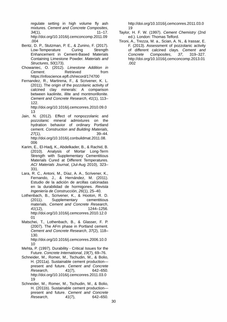
Zunino, 2017; Chowaniec, 2012; Matschei, Lothenbach, & Glasser, 2007). The solubility of limestone is increased at lower temperatures, which is reported to lead to enhanced precipitation of carbonate-AFm phases, leading to a decrease in porosity (Bentz, Stutzman, & Zunino, 2017). The combination of metakaolin and limestone in OPC-based systems can give synergetic benefits from both well-known systems. The additional reactive alumina supplied by metakaolin can enhance limestone reaction and allow higher replacement levels with improved performance (Antoni, Rossen, Martirena, & Scrivener, 2012; Avet, Snellings, Alujas Diaz, Ben Haha, & Scrivener, 2016). For this reason, so called, LC3 (limestone calcined clay cements) have become of great interest. This study explores the effect of calcined metakaolin content on early-age performance of LC3 by dilution of pure metakaolin using limestone. The effect of particle size of the limestone fraction on strength and mixture design strategies to increase early-age performance are also discussed. 2. MATERIALS AND METHODS Portland cement classified as CEMI 42.5R was used for the preparation of blended cement pastes. The limestone powders were supplied from commercial manufacturers and were used as received. A pure metakaolin (95% purity) was used in this study. Lower grades of clay were achieved by dilution of the pure metakaolin with limestone. A base mixture design of LC3-50 with clay-to-limestone ratio of 2:1 was used (50% clinker, 30% calcined clay, 15% limestone and 5% gypsum). From there, different levels of dilution were explored by combining pure metakaolin and additional limestone in the 30% clay fraction of the binder, ranging from 95% metakaolin content (pure metakaolin without dilution) down to 20% metakaolin content (6.3% pure metakaolin combined with 23.7% limestone). A volumetric water-to-solids ratio of 1.23 (equivalent to w/c 0.4 for OPC) was kept constant among all mixtures. For MIP measurements, paste samples were used after hydration stoppage using solvent exchange procedure (isopropanol). 3. INFLUENCE OF CALCINED KAOLINITE CONTENT Figure 1 shows compressive strength results of LC3 systems with different levels of dilution of the pure metakaolin by limestone. As observed, at 1 day the strength is independent of the grade (i.e. metakaolin content) of the calcined clay fraction, and it is only a function of the clinker factor. At two and 3 days, there is a clear trend towards higher strength values as the metakaolin content increases. This trend is maintained at later ages. However, it can be observed that from 7 days
onwards, the strength of the LC3 systems with metakaolin contents between 40 and 71% is almost the same. Previous studies showed a stronger dependence of strength with the calcined kaolinite content of the calcined clay (Avet et al., 2016). Thus, further experiments were conducted to clarify the role of the other constituents, particularly limestone, on strength development.
Figure 1. Compressive strength of LC3-50 mortars with different metakaolin contents at 1, 2, 3, 7, 28 and 90 days. 4. Influence of limestone particle size The results presented in the previous section were obtained using a relatively fine limestone powder (specific surface area 3.6 m2/g, about 3 times the surface of the cement used). Therefore, it was suspected that the independence of strength in the medium range of metakaolin contents from 7 days onwards could be explained by the introduction of the fine limestone for metakaolin dilution, which provides additional nucleation sites for clinker as compared to a coarser limestone fraction. A coarser limestone (D15), with a specific surface area similar to OPC (1.4 m2/g) was selected to dilute metakaolin and mortars with 95, 63 and 40% metakaolin content were prepared. The results are shown on Figure 2 along with the corresponding mixtures using fine limestone. As seen, with coarse limestone, the dependence of strength with metakaolin content on calcined clay is clear. This suggests that a refinement of the limestone fraction may be an effective strategy to increase the strength of LC3 when low grade (below 50% metakaolin content) clays are available, reaching mechanical performance comparable to high grade clays.
Figure 2. Compressive strength of LC3-50 mortars with fine and coarse (D15) limestone at 1, 2, 3, 7, 28 and 90 days. Another consequence of the introduction of coarse limestone particles, in combination with a fraction of fine ones (as in the case of D15) is a reduction of the total porosity at early age. Figure 3 shows the porosity measured by MIP on paste samples at 1 day of hydration. It can be observed that, between fine and coarse limestone, the critical entry radius remains fairly constant. However, the
29
total porosity of the system containing D15 is lower as compared to their counterparts with fine limestone. This is attributed to an increased packing capacity of the system, which also should have a positive effect in the workability of the system.
Figure 3. Porosity profile of OPC and LC3-50 at 1 day (contact angle 120º) with fine and coarse (D15) limestone. 5. STRATEGIES TO INCREASE EARLY-AGE STRENGTH One of the points for improvement on the LC3 technology is the early age (1 to 3 days) strength as compared to OPC. During this period, the reaction degree of metakaolin is small and therefore, the strength is mainly controlled by the amount and rate of reaction of cement. Different strategies were explored as conceptual trials to explore strategies to offset the strength difference observed. Two chemical strategies, alkali content adjustment using KOH (coded OH) and addition of calcium chloride (coded 2Cl), are compared with two physical strategies, use of nano-limestone (coded nLS) and a bimodal limestone powder (BUG), which combines very fine (0.5 µm) and coarse (60 µm) particles. The results are presented in Figure 4 for a 40% metakaolin content system, and compared with a 100% OPC reference. For the alkali adjustment, KOH was added until reaching 0.8% Na2OEQ in the system. In the case of calcium chloride, 2% by mass of cement of calcium chloride dihydrate was added. As observed, both nLS and BUG offer some improvement at early-age. The alkali adjustment also appears to be a promising strategy. However, the strength at later ages is lower, which indicates that the dosage used for the trial mixture is too high and requires further adjustment. A surprising result is the ineffectiveness of calcium chloride, a well-known hydration accelerator. X-Ray diffraction measurements showed that the chlorides are quickly bound in Friedel’s salt due to the high availability of aluminates in the system. This is likely to prevent the acceleration effect to take place in the same manners as it would happen in an OPC system.
Figure 4. Compressive strength of LC3-50 mortars applying different strategies to increase early-age strength, at 1, 2, 3, 7, 28 and 90 days. 6. CONCLUSIONS This study explored the effect of clay dilution on LC3 systems, and other characteristics of the raw materials (limestone) that can influence strength development. Finally, some insights on strategies to increase early-age strength are given. From the results presented the following conclusions can be drawn:
1. Calcined kaolinite content is strongly correlated with compressive strength of LC3 systems. However, other design parameters such as limestone fineness can be adjusted to increase performance in scenarios where only low-grade clays are available.
2. The use of fine limestone in combination with a fraction of coarse particles allows to increase early-age strength. Adjustment of the alkali content of LC3 is another effective strategy that will be further studied. However, the dosage should be carefully adjusted to prevent negative impacts in long term strength.
REFERENCES Antoni, M., Rossen, J., Martirena, F., & Scrivener,
K. (2012). Cement substitution by a combination of metakaolin and limestone. Cement and Concrete Research, 42(12), 1579–1589. http://doi.org/10.1016/j.cemconres.2012.09.006
Avet, F., Snellings, R., Alujas Diaz, A., Ben Haha, M., & Scrivener, K. (2016). Development of a new rapid, relevant and reliable (R3) test method to evaluate the pozzolanic reactivity of calcined kaolinitic clays. Cement and Concrete Research, 85, 1–11. http://doi.org/10.1016/j.cemconres.2016.02.015
Bentz, D. P., Ferraris, C. F., Jones, S. Z., Lootens, D., & Zunino, F. (2017). Limestone and Silica Powder Replacements for Cement: Early-Age Performance. Cement and Concrete Composites, 78, 43–56. http://doi.org/10.1016/j.cemconcomp.2017.01.001
Bentz, D. P., Sato, T., De La Varga, I., & Weiss, W. J. (2012). Fine limestone additions to
30
regulate setting in high volume fly ash mixtures. Cement and Concrete Composites, 34(1), 11–17. http://doi.org/10.1016/j.cemconcomp.2011.09.004
Bentz, D. P., Stutzman, P. E., & Zunino, F. (2017). Low-Temperature Curing Strength Enhancement in Cement-Based Materials Containing Limestone Powder. Materials and Structures, 50(173).
Chowaniec, O. (2012). Limestone Addition in Cement. Retrieved from https://infoscience.epfl.ch/record/174700
Fernandez, R., Martirena, F., & Scrivener, K. L. (2011). The origin of the pozzolanic activity of calcined clay minerals: A comparison between kaolinite, illite and montmorillonite. Cement and Concrete Research, 41(1), 113–122. http://doi.org/10.1016/j.cemconres.2010.09.013
Jain, N. (2012). Effect of nonpozzolanic and pozzolanic mineral admixtures on the hydration behavior of ordinary Portland cement. Construction and Building Materials, 27(1), 39–44. http://doi.org/10.1016/j.conbuildmat.2011.08.006
Karim, E., El-Hadj, K., Abdelkader, B., & Rachid, B. (2010). Analysis of Mortar Long-Term Strength with Supplementary Cementitious Materials Cured at Different Temperatures. ACI Materials Journal, (Jul-Aug 2010), 323–331.
Lara, R. C., Antoni, M., Díaz, A. A., Scrivener, K., Fernando, J., & Hernández, M. (2011). Estudio de la adición de arcillas calcinadas en la durabilidad de hormigones. Revista Ingeniería de Construcción, 26(1), 25–40.
Lothenbach, B., Scrivener, K., & Hooton, R. D. (2011). Supplementary cementitious materials. Cement and Concrete Research, 41(12), 1244–1256. http://doi.org/10.1016/j.cemconres.2010.12.001
Matschei, T., Lothenbach, B., & Glasser, F. P. (2007). The AFm phase in Portland cement. Cement and Concrete Research, 37(2), 118–130. http://doi.org/10.1016/j.cemconres.2006.10.010
Mehta, P. (1997). Durability - Critical Issues for the Future. Concrete International, 19(7), 69–76.
Schneider, M., Romer, M., Tschudin, M., & Bolio, H. (2011a). Sustainable cement production—present and future. Cement and Concrete Research, 41(7), 642–650. http://doi.org/10.1016/j.cemconres.2011.03.019
Schneider, M., Romer, M., Tschudin, M., & Bolio, H. (2011b). Sustainable cement production—present and future. Cement and Concrete Research, 41(7), 642–650.
http://doi.org/10.1016/j.cemconres.2011.03.019
Taylor, H. F. W. (1997). Cement Chemistry (2nd ed.). London: Thomas Telford.
Tironi, A., Trezza, M. a., Scian, A. N., & Irassar, E. F. (2013). Assessment of pozzolanic activity of different calcined clays. Cement and Concrete Composites, 37, 319–327. http://doi.org/10.1016/j.cemconcomp.2013.01.002
31
Young Researchers’ Forum IV Innovation in Construction Materials 09 April 2018 Paper Number 06
Development of Optimum Cold-formed Steel Beams in Bending, Shear and Web Crippling
Ye, J., Shepherd, P.
University of Bath, UK Poologanathan, K., Ma, L., Dobson, R.
Northumbria University, UK Gunalan, S.
Griffith University, Australia Huang, S.
University of Sheffield, UK ABSTRACT The use of cold-formed steel (CFS) members in low rise building construction and modular building systems has increased significantly in recent times. Cold-formed steel beams can be optimised to increase their load carrying capacity, leading to more efficient and economical structural systems. This paper aims to provide a methodology that would enable the development of optimised cold-formed steel beams with maximum flexural, shear and web crippling strength for practical applications. The optimised sections are designed to comply with the Eurocode 3 (EC3) geometrical requirements as well as with a number of manufacturing and practical constraints. In this research, shape optimisation method is developed to obtain high structural resistance of cold-formed steel beams by taking into account the bending, shear and web crippling actions. First the flexural strengths of the sections are determined based on the effective width method adopted in EC3, while the optimisation process is performed using the Optimisation method. To allow for the development of a new ‘folded-flange’ cross-section, the effective width method in EC3 is extended to deal with the possible occurrence of multiple distortional buckling modes. In total, five different CFS channel cross-section are considered in the optimisation process. The flexural strengths of the optimised sections are then verified using detailed nonlinear finite element analysis. The results indicate that the optimised folded-flange section provides a bending capacity which is up to 50% higher than the standard optimised shapes with the same amount of material. Shear, web crippling behaviour of five optimised cold-formed steel beams were investigated using detailed nonlinear finite element analysis. Finally, innovative optimised cold-formed steel beam was proposed to obtain high structural resistance by taking into account the flexural, shear and web crippling behaviour. Innovative optimised cold formed steel beams can be used in lightweight forms of building constructions and modular building system. 1. INTRODUCTION The use of cold-formed steel (CFS) members in low rise building construction and modular building systems has increased significantly in recent times. More than 70% of all steel building construction is expected to be cold-formed in the near future. In recent years, CFS cross-sections are increasingly being used as primary structural elements. For example, CFS framing systems are used in low- to mid-rise multi-storey buildings (Fiorino et al., 2014) and CFS portal frames are gaining popularity in single-storey industrial buildings (Lim and Nethercot, 2003 and 2004). Compared to hot-rolled members, CFS thin walled members offer several advantages of economy and efficiency, including a high strength for a light weight, a relatively straightforward manufacturing process and an ease of transportation and erection. Above all, CFS sections offer flexibility and versatility in producing a variety of cross-sectional shapes, which are obtained by bending
relatively thin metal sheets using either a cold-rolling or a press-braking process at room temperature. Figure 1 shows the commercially available CFS sections with complex shapes. The flexibility of the manufacturing process in obtaining various shapes means that there is a great potential for CFS sections to be optimised to meet specific objectives, thereby bringing practical benefits to both manufacturers and structural designers. Due to their typically large flat width-to-thickness ratios, CFS sections are inherently susceptible to local, distortional and global buckling modes, resulting in a complex optimisation process. Previous studies on the optimisation of CFS elements have mainly been limited to varying the dimensions of standard cross-sections such as lipped channel beams (Lee et al., 2005), channel columns with and without lips (Tian and Lu, 2004; Lee et al., 2006) and hat, I- and Z- cross section CFS beams (Adeli and Karim, 1997). Taking the elastic buckling strength as an optimisation
32
criterion, Magnucki et al. (2006a, b) developed optimum CFS beams with a monosymmetrical open cross-section and sinusoidally corrugated flanges, as well as optimum I-shaped sections with box-shaped flanges. More recently, CFS compression and bending members (Ma et al., 2015; Ye et al., 2015) were optimised with respect to their capacity according to EC3 (CEN, 2005) using Genetic Algorithms. The researchers investigated the influence of the column length and the shift of the effective centroid, induced by local/distortional buckling, on the optimal design solutions. The shapes of the cross-section were thereby limited to the conventionally used lipped channels.
Figure 1. Commercially available CFS sections with complex shapes In order to obtain ‘global optimum’ solutions, research at Johns Hopkins University and Griffith University was conducted on the free form optimisation of CFS cross-sections without placing any prior constraints on the shape of the cross-section. The finite strip method (FSM) and the direct strength method (DSM [14]) were thereby combined with Genetic Algorithms (GA) to obtain optimum shapes for open CFS cross section columns (Leng et al., 2011; Gilbert et al., 2012; Liu et al., 2004). While this led to some innovative new geometries, the resulting cross sections were not ‘pre-qualified’ according to the DSM approach, thus casting some doubt on the optimisation procedure. Additionally, these studies did not consider any manufacturing or construction constraints and, therefore, highly complex shapes were obtained which cannot be deemed suitable for practical applications due to a complex manufacturing process and the obvious difficulty in connecting the cross-section to other elements. Leng et al. (2014) later advanced this work by incorporating some end-user constraints and by limiting the numbers of rolling passes in the manufacturing process. CFS columns with different lengths were optimised and more practical shapes were obtained, which, however, still did not meet the DSM prequalification criteria.
This study aims to develop optimum cold-formed steel beams in bending, shear and web crippling. In total, five different CFS channel cross-section are considered in the optimisation process. All sections are optimised by maximising the cross-sectional flexural, shear and web crippling capacity for a given thickness and coil width (equal to the total developed length of the cross-section). UK’s construction sector has been followed by rising costs, low productivity and a heavy reliance on traditional building methods. UK lags behind countries in Europe, North America and Asia with a modular building sector in its infancy. Currently, it is a $4.5 billion sector, which is only 3% of a $150 billion construction industry. By comparison, Sweden’s prefabricated modular housing is about 70% of its construction industry. It has been reported that UK government are planning a new wave of modular building in a drive to solve Britain’s housing crisis. More than 100,000 modular homes could be constructed as the UK government looks at ways to meet its target to provide a million new homes by 2020. Hence there is a need to develop a light weight modular building with enhanced structural performance. Figures 2 and 3 shows the application of cold-formed steel sections in modular building systems. Optimum cold-formed steel beams considered in this research study can be used in lightweight forms of building constructions and modular building system.
Figure 2. Light steel framework of a module
33
Figure 3. High-rise modular building, Wembley, UK 2. PARTICLE SWARM OPTIMISATION PROCESS (PSO) Particle swarm optimisation (PSO) is a population-based method which is inspired by the swarming behaviour of biological populations such as the motion of bird flocks or schools of fish (PSO, 2009). Its mechanism has some parallels with evolutionary computation techniques, such as Genetic Algorithms (GA). An initial population of solutions is randomly generated, but unlike GA, solutions are optimised by updating generations without any evolution operators such as crossover or mutation. The potential solutions in PSO, called particles, move in the problem space by following the current optimum particles. This usually leads to a better efficiency in terms of computational time and cost and, therefore, a faster convergence rate compared to GA (Hassan et al., 2005; Jeong et al., 2009). A swarm comprises of N particles moving around a D-dimensional search space, in which each particle represents a potential solution to the optimisation problem. The position and velocity vectors of ith particle are ρ = {ρ , ρ , ... , ρ , ... , ρ } i i1 i2 ij iD and Vi = {vi1, vi2, ... , vij, ... , viD}, respectively, where i = 1, 2, 3, ... N. The particles fly through the feasible region in search for the global optimal solution. In each iteration step, the ith particle updates its position and velocity based on a combination of: (a) its personal best position over its history, and (b) the position of the particle within the swarm with the best position in the previous iteration. The optimisation procedure in this research study aimed to maximise the bending capacity (Section Moment Capacity) of cold-formed steel cross-sections. The optimisation problem can be expressed as:
max (Mc,Rd = Weff (x)⋅fy ) dmin ≤ xi ≤ dmax for i = 1, ... , N (1) where Mc,Rd is the moment resistance of a cross-section about its major axis and Weff (x) is the effective section modulus. The effective section modulus Weff is calculated about the major principal axis through the centroid of the effective area. The effective width and the effective thickness of each plate element are first calculated according to the procedure outlined in Eurocode 3, Part 1.3 to account for both local and distortional buckling. The effective second moment of area of the cross section Ieff is then calculated from the contributions of all effective parts of the cross-section and divided by the maximum distance from the effective centroid to the edge of the cross-section to obtain Weff. For each design variable, xi, lower and upper bounds, dmin and dmax, were determined based on a combination of the constraints imposed by EC3 (CEN, 2005) and certain manufacturing limitations and practical considerations, which will be explained further in this section. Throughout the optimisation process, the thickness of the cross sections was kept constant at 1.5 mm and the total developed length of the cross-section (the coil width) was also maintained at 415 mm. These values were taken from a commercially available channel section, shown in Figure 4, which was used as a benchmark and to which the performance of the optimised sections will be compared in this section. The values of the radius of the rounded corners (measured along the heart-line), the elastic modulus and the Poisson's ratio were taken as 3 mm, 210 GPa and 0.3, respectively. The yield stress of the CFS material was assumed to be fy = 450 MPa. It is again noted that the optimisation was carried out with respect to the cross-sectional capacity, excluding lateral-torsional buckling. This situation is representative, for instance, of purlins connected to a steel deck with concrete topping, where the compression flange is continuously supported, or even of roof purlins where the lateral and rotational stiffness of the roof diaphragm and/or the presence of sufficient bridging prevent any out-of-plane effects. EC3 (CEN, 2005) design rules also impose certain limits on the plate width-to-thickness ratios, the relative dimensions of the cross section and the angle of the edge stiffeners. These constraints were also taken into account in the optimisation procedure. One of the major advantages of the PSO algorithm is that these constraints can easily be accommodated and others added. The constraints merely result in a restriction of the search space of the particle swarm.
34
Figure 4. Selected commercial lipped channel beam cross-section (dimensions in mm). To facilitate the optimisation process, both the design procedure and the optimisation algorithm were implemented in Matlab (2011). The population size of the particle swam N was taken as 100, and 100 iterations kmax were used to obtain the optimum results. The maximum and minimum inertial weight factors wmax and wmin were taken as 0.95 and 0.4, respectively. Each of the prototypes was optimised 3 times using a different set of random initial particles and the result with the maximum bending capacity was retained as the optimum section. Figure 5 shows the selected prototypes while Table 1 shows the geometrical details and section moment capacities (Bending) of the optimised cold-formed steel beams.
(1) (2) (3)
(4) (5) Figure 5. Selected prototypes
Table 1. Geometrical details and section moment capacities (Bending) of the optimised cold-formed steel beams
3. FINITE ELEMENT MODELS Detailed geometric and material non-linear finite element analyses were performed using ABAQUS Version 6.14 to evaluate the flexural behaviour and capacity of the optimised cross-sections for the five considered prototypes (see Table 1) as well as the standard lipped channel beams. The main purposes of the finite element analyses were: (a) to examine the accuracy of the method proposed in Section 2 for the flexural design of folded-flange cross sections; and (b) to investigate the overall effectiveness of the developed optimisation framework in obtaining sections with increased bending capacity (section moment capacity). Additional nonlinear finite element analyses were also performed using ABAQUS to investigate the shear and web crippling behaviour and capacity of the optimised cross-sections for the five considered prototypes. The centreline dimensions were used to model the optimised cold-formed steel beams in ABAQUS using middle surface shell offset definition. Bending The FE models were developed in ABAQUS using the general-purpose S4R element (Figure 6). This element is a 4-node quadrilateral shell element with reduced integration. Through a sensitivity analysis, a mesh size of 5 mm x 5 mm for the flat plate sections, with smaller elements used in the rounded corner sections was found to be appropriate. The effects of geometric imperfections were included in the FE analysis by scaling the local and distortional modes to specific amplitudes and superposing them onto the initial perfect geometry.
35
Figure 6. FE model of the folded-flange beam (Prototype 4) subjected to bending
Figure 7. Bending failure mode of optimised cold-formed steel beam (Prototype 5) To simulate pin-ended boundary conditions with prevented warping (consistent with the assumptions made in the optimisation process), the nodes of each end section of the CFS member were coupled to the central point of the web (acting as the master node). The external load was then applied in the form of uniform rotations of the end sections about the major axis, using a displacement control regime. The boundary conditions and the applied loading are shown in Figure 6 while Figure 7 shows the FE model of the folded-flange beam (Prototype 5) subjected to bending. Large deformation effects were included in the element formulation and a geometric nonlinear analysis was carried out in order to be able to accurately track the post-buckling behaviour of the CFS beams. It is worth mentioning that the modelling techniques utilised in this study, including the type of elements, the material behaviour, the meshing and the imperfection modelling borrow heavily from the work by Haidarali and Nethercot (2011) and Shifferaw and Schafer (2012). These techniques have been extensively verified against experimental results (Schafer, 2003 and 2006), demonstrating excellent predictive capability with an average error typically less than 4%. Table 2 shows the comparison of the section moment capacities (bending) of the optimised and standard sections obtained from EC3 and FE analysis.
Table 2. Comparison of the section moment capacities (bending) of the optimised and standard sections obtained from EC3 and FE analysis.
Shear This section describes the development of finite element (FE) models to investigate the shear behaviour of optimised cold-formed steel beams. For this purpose, a general-purpose finite element program, ABAQUS, was used. Appropriate parameters were chosen for the geometry, mechanical properties, loading and support conditions.
FE models of simply supported single optimised cold-formed steel beams with shear centre loading. ABAQUS has several element types to simulate the shear behaviour of optimised cold-formed steel beams. In this study, shell element was selected as it has the capability to simulate the elastic buckling and nonlinear ultimate shear behaviour of thin steel beams. The shell element S4R in ABAQUS was used to model the optimised cold-formed steel beams. Two methods of analysis were used. Bifurcation buckling analyses were first used to obtain the eigenvectors for the inclusion of initial geometric imperfections in non-linear static analysis. Non-linear static analyses including the effects of large deformation and material yielding were then employed to investigate the shear behaviour and strength of optimised cold-formed steel beams until failure. In this study, the required numbers of elements to model flange and web elements of optimized cold-formed steel beams were chosen based on convergence studies. These convergence studies showed that in general, the use of element sizes of approximately 5 mm x 5 mm was able to simulate the shear buckling and yielding deformations and provided accurate shear capacity results for all the sections. The geometry and finite element mesh of optimised cold-formed steel beams are shown in Figure 8.
36
Figure 8. FE model of the folded-flange beam (Prototype 5) subjected to shear failure
Figure 9. Shear failure mode of optimised cold-formed steel beam (Prototype 5) The ABAQUS classical metal plasticity model was used in all the analyses. This model implements the von Mises yield surface to define isotropic yielding, associated plastic flow theory, and either perfect plasticity or isotropic hardening behaviour. A perfect plasticity model was adopted in all the FE models with nominal yield stresses. Keerthan and Mahendran (2011) showed that the use of measured strain hardening in the web element in finite element analyses (FEA) improved the shear capacity by less than 1%. Hence strain hardening was not considered in the analyses. The elastic modulus and Poisson’s ratio were taken as 200 GPa and 0.3, respectively. Simply supported boundary conditions were implemented in the FE models of optimised cold-formed steel beams. Left and right supports: ux = restrained θx = free uy = restrained θy = free uz = free θz = restrained Mid-span loading point: ux = restrained θx = free uy = free θy = free uz = restrained θz = restrained Strap Location:
ux = restrained θx = free uy = free θy = free uz = free θz = restrained Note: ux, uy and uz are translations and θx, θy and θz are rotations in the x, y and z directions, respectively. Figure 10 shows the applied loads and boundary conditions of the FE model while Figure 11 shows the shear failure mode of optimised cold-formed steel beam (Prototype 3). The point load and simply supported boundary conditions were used at the shear centre using a fixed node to eliminate twisting of the section (see Figure 10). The vertical translation was not restrained at the loading point. Full height web side plates were modelled as 20 mm thick rigid plates. The magnitude of local imperfections was taken as 0.006d1 for all optimised cold-formed steel beams (Keerthan and Mahendran, 2014). The critical imperfection shape was introduced using the *IMPERFECTION option in ABAQUS. Preliminary FEA showed that the effect of residual stresses on the shear capacity of cold-formed steel beams is less than 1%. Therefore, the effect of residual stresses on the shear capacity of optimised cold-formed steel beams is also likely to be very small. Hence the residual stresses were not considered in the FEA of optimised cold-formed steel beams. Web Crippling In this section the finite element models were developed to simulate the web crippling behaviour of optimized cold-formed steel beams under ITF load cases. Finite element models were developed using ABAQUS, and analysed using the quasi-static analysis method. Quasi-static analysis was used to overcome the possible convergence and contact difficulties faced in the non-linear static analysis of the web crippling behaviour of optimized cold-formed steel beams. Three-dimensional deformable S4R shell elements were used to model optimized cold-formed steel beams while loading and support bearing plates and web side plates were all modelled using four node rigid body elements R3D4. The web and flange elements of optimized cold-formed steel beams were modelled using 5 mm x 5 mm elements except at the corners. The optimized cold-formed steel beams’ inside bent radius has a significant influence on its web crippling behaviour thus more elements are needed to model the corners. Hence 1 mm x 5 mm elements were used to model the corners as shown in Figure 10. Rigid body elements used to model web side plates and loading and support bearing plates were 10 mm x 10 mm as their sizes do not influence the web crippling behaviour.
37
The ABAQUS classical metal plasticity model was used in all the analyses. Since analyses are based on quasi-static method, the modelled elements need to have mass or inertia values. Therefore, the typical steel density of 7850 kg/m3 (7.85x10⁻⁹ tonne/mm3 in ABAQUS) was used here.
Figure 10. FE model of the folded-flange beam (Prototype 5) subjected to web crippling (ITF Load case) Boundary conditions were assigned to the reference points of loading and support bearing plates. Figures 10 show the boundary conditions applied to optimized cold-formed steel beams subject to ITF load case. The loading plate at the top was assigned displacement control using smooth step amplitude to impose smooth loading on the flange of optimized cold-formed steel beam. The loading plate was free to move vertically while its vertical displacement was limited to 20 mm. Translations along both lateral and longitudinal axes and rotation about the longitudinal axis of the loading plate were restrained. Simply supported condition was simulated at the bottom support plates by using pin and roller boundary conditions in the support bearing plates. ie. as shown in Figure 10, translations of support plate-1 in all three directions and rotation about the longitudinal (z) axis were restrained to simulate pin support while translation of support plate-2 along lateral (x) and longitudinal (z) axis and rotation about longitudinal (z) axis were restrained. Lateral axis translation was restrained at quarter points.
Figure 11. Web crippling failure mode (ITF Load Case) of optimised cold-formed steel beam (Prototype 5) Web side plates were simulated by rigid plates and tie contact constraints were applied between the rigid plates and the web of the optimized cold-formed steel beams. The connections between the bearing plates and the optimized cold-formed steel beam’s flanges were modelled using contact surfaces to simulate the true behaviour accurately as shown in Figure 10. Web side plates were modelled using discrete rigid elements and assigned with tie contact as shown in Figure 10. In the models used here, surface-to-surface contact was assigned between the shell FE model representing optimized cold-formed steel beams and the rigid plates representing bearing plates. Separations were allowed between the contact surfaces after the initial contact. The friction between contact surfaces was set to 0.4 and contact surfaces were assigned to hard surfaces using hard contact pressure overclosure. Quasi-static analytical option was chosen in this study. Kaitila (2004), Natario et al. (2014a, b) and Sundararajah (2016 and 2017) also used quasi-static analysis method in their web crippling studies as improved analytical approach. Displacement rate of 0.7 mm/minute was considered until failure. Table 3 shows the bending, shear and web crippling capacities of optimised and standard cold-formed steel beams from FEA. Table 3 shows the increased efficiency of the proposed folded-flange prototype (Prototype 5) compared to any other prototype considered. It is shown that, for the same amount of material, prototype 5 leads to a maximum flexural capacity which is around 50% higher than the standard commercially available channel section. Folded-
38
flange sections are also easy to manufacture and connect to typical floor systems and modular building system and, hence, are suitable for practical CFS beam sections. However it was found that shear and web crippling capacities of proposed folded-flange prototype (Prototype 5) reduced by 15% and 55%, respectively when it compared with standard commercially available channel section. Table 3. Finite element analyses results
Prototypes Bending (Section Moment Capacity) (kNm) Ms
Ms (%)
Shear Capacity (kN) Vv
Vv
(%) Web Crippling Capacity (kN) Rb
Rb (%)
LCB (Standard)
10.4 100% 53.7 100% 14.06 100%
1 (UCB) 9.11 88% 42.86 80% 12.59 90%
2 (LCB) 12.73 122% 54.32 101% 14.67 104%
3 12.33 119% 53.86 100% 14.69 104%
4 14.09 135% 53.45 100% 14.63 104%
5 15.52 149% 45.93 86% 6.35 45%
Table 3 shows that for the same amount of material, Prototype 4 leads to a higher flexural capacity which is around 35% higher than the standard commercially available channel section. Prototype 4 sections are also easy to manufacture and connect to typical floor systems and modular building system and, hence, are suitable for practical CFS beam sections. It was found that the shear and web crippling capacities of proposed Prototype 4 did not reduce when it compared with standard commercially available channel section. 5. CONCLUSIONS This paper presents the development of optimum cold-formed steel beams in bending, shear and web crippling. In this research, shape optimisation method is developed to obtain high structural resistance of cold-formed steel beams by taking into account the bending, shear and web crippling actions. First the flexural strengths of the sections are determined based on the effective width method adopted in EC3, while the optimisation process is performed using the Optimisation method. The flexural strengths of the optimised sections are then verified using detailed nonlinear finite element analysis. Shear, web crippling behaviour of 5 optimised cold-formed steel beams were investigated using detailed nonlinear finite element analysis. Finally, innovative optimised cold-formed steel beam was proposed to obtain high structural resistance by taking into account the flexural, shear and web crippling behaviour. It was found that same amount of material, prototype 5 leads to a maximum flexural capacity
which is around 50% higher than the standard commercially available channel section. Folded-flange sections are also easy to manufacture and connect to typical floor systems and modular building system and, hence, are suitable for practical CFS beam sections. However, it was found that shear and web crippling capacities of proposed folded-flange prototype (Prototype 5) reduced by 15% and 55%, respectively when it compared with standard commercially available channel section. It was found that section moment capacity of proposed prototype 4 increased by 35% and shear and web crippling capacities of proposed prototype 4 did not reduce when it compared with standard commercially available channel section. Optimised cold-formed steel beams (Prototypes 4 and 5) can be used in lightweight forms of building constructions and modular building system. REFERENCES Adeli, H. and Karim, A., 1997, Neural network
model for optimization of cold-formed steel beams. J. Struct. Eng.-ASCE.123: 1535–1543.
CEN, Eurocode 3, 2005, Design of steel structures, part 1.3: general rules—supplementary rules for cold-formed steel members and sheeting, in, brussels: European comittee for standardization.
Fiorino, L., Luorio, O. and Landolfo, R., 2014, Designing CFS structures: the new school BFS in naples. Thin Wall Struct. 78: 37–47.
Haidarali, M.R. and Nethercot, D.A., 2011, Finite element modelling of cold-formed steel beams under local buckling or combined local/distortional buckling. Thin Wall Struct. 49: 1554–1562.
Hassan, R. Cohanim, B., De Weck, O., Venter, G., 2005, A comparison of particle swarm optimization and the genetic algorithm, in: Proceedings of the 1st AIAA Multidisciplinary Design Optimization Specialist Conference. 18–21.
Jeong, S., Hasegawa, S., Shimoyama, K. and Obayashi, S., 2009, Development and investigation of efficient GA/PSO-hybrid algorithm applicable to real-world design optimization, IEEE Comput. Intell. 4: 36–44.
Kaitila, O., 2004, Web crippling of cold-formed thin-walled steel cassettes. PhD Thesis, Helsinki University of Technology, Finland.
Keerthan, P. and Mahendran, M., 2011, New design rules for the shear strength of LiteSteel beams. Journal of Constructional Steel Research. 67: 1050–1063
Keerthan, P. and Mahendran, M., 2014, Improved shear design rules for lipped channel beams with
39
web openings. Journal of Constructional Steel Research. 97: 127-142.
Lee, J., S.M. Kim, S.M., Park, H.S and Woo, Y.H,
2005, Optimum design of cold-formed steel channel beams using micro genetic algorithm. Eng. Struct. 27: 17–24.
Lee, J.H., Kim, S.M. and Park, H.S., 2006, Optimum design of cold-formed steel columns by using micro genetic algorithms. Thin Wall Struct. 44: 952–960.
Leng, J.Z., Guest, J.K and Schafer, B.W, 2011, Shape optimization of cold-formed steel columns. Thin Wall Struct. 49: 1492–1503.
Leng, J.Z, Li, Z.J., Guest, J.K and Schafer, B.W, 2014, Shape optimization of cold-formed steel columns with fabrication and geometric end-use constraints. Thin Wall Struct. 85: 271–290.
Lim, J.B.P. and Nethercot, D.A, 2003, Ultimate strength of bolted moment-connections between cold-formed steel members. Thin Wall Struct. 41: 1019–1039.
Lim, J.B.P. and Nethercot, D.A, 2004, Finite element idealization of a cold-formed steel portal frame. J. Struct. Eng. – ASCE. 130: 78–94.
Liu, H. Lgusa, T. and Schafer, B.W, 2004, Knowledge-based global optimization of cold formed steel columns. Thin Wall Struct. 42: 785–801.
Ma, W., Becque, J., Hajirasouliha. I. and Ye, J., 2015, Cross-sectional optimization of cold formed steel channels to Eurocode 3. Eng. Struct. 101: 641–651.
Magnucki, K., Maćkiewicz, M. and Lewiński, J., 2006a, Optimal design of a mono-symmetrical open cross section of a cold-formed beam with cosinusoidally corrugated flanges. Thin Wall Struct. 44: 554–562.
Magnucki, K., Maćkiewicz, M. and Lewiński, J., 2006b, Optimization of mono- and anti-symmetrical I-sections of cold-formed thin-walled beams. Thin Wall Struct. 44: 832–836.
Mathworks, Matlab R 2011, in, Mathworks, Inc, 2011.
Natário, P., Silvestre, N. and Camotim, D. 2014a, Web crippling failure using Quasi-Static FE models. Thin-Walled Structures. 84: 34-49.
Natário, P., Silvestre, N. and Camotim, D., 2014b, Computational modelling of flange crushing in cold-formed steel sections. Thin-Walled Structures. 84: 393-405.
Shifferaw, Y. and Schafer, B.W., 2012, Inelastic bending capacity of cold-formed steel members. J. Struct. Eng.-ASCE. 138: 468–480.
Sundararajah, L., Mahendran, M. and Keerthan, P., 2016, Experimental studies of lipped channel beams subject to web crippling under two-flange load cases. ASCE Journal of Structural Engineering. 142-9.
Sundararajah, L., Mahendran, M. and Keerthan, P., 2017, New design rules for lipped channel beams subject to web crippling under two-flange
load cases. Thin-Walled Structures.119: 421-437.
Swarm Intelligence for Multi-objective Problems in Data Mining, 2009, Stud Comput Intell. 242: 1-287.
Tian, Y.S. and Lu, T.J., 2004, Minimum weight of cold-formed steel sections under compression. Thin Wall Struct. 42: 515–532.
Ye, J., Hajirasouliha, I., Becque, J., Eslami, A., 2015, Optimum design of cold-formed steel beams using particle swarm optimisation method, J. Constr. Steel Res.
Yu, C. and Schafer, B.W., 2003, Local buckling tests on cold-formed steel beams. J. Struct. Eng. – ASCE. 129: 1596–1606.
Yu, C. and Schafer, B.W., 2006, Distortional buckling tests on cold-formed steel beams, J. Struct. Eng. – ASCE. 132: 515–528.
40
41
Young Researchers’ Forum IV Innovation in Construction Materials 09 April 2018 Paper Number 07
Combined effect of Polymeric Fibres and SAP on the Performance of Concrete and Repair Mortars: A review
R. Rostami, A.J. Klemm and F.C.R. Almeida
School of Engineering and Built Environment, Glasgow Caledonian University, UK ABSTRACT One of the most common problems in the use of cementitious materials is shrinkage due to the hydration reaction. This process often leads to cracks in the cement matrix in the early days after casting. This phenomenon is more marked in supplementary cementitious materials (SCMs) which contain fine aggregate or that are subject to a rapid evaporation of the water contained in the mix. This paper aims to review the mechanisms of shrinkage reduction by using polymeric fibers and superabsorbent polymers (SAPs). The effects of both materials on the performance of concrete and repair mortars are also discussed. In general, the fibers give an additional tensile strength to withstand the stresses induced by shrinkage. One the other hand the SAPs absorb water during the mixing and release it during hydration favouring internal curing. The effect of SCMs and SAPs on improving the bond between fibres and the cement paste need to be further studied. 1. INTRODUCTION The current construction industry is faced with ever rising demands for safer and more cost-effective infrastructure. The way to address these requirements is to look towards multidisciplinary approaches in the developments of new sustainable building materials but also in the developments of new repair technologies. Using Supplementary cementitious materials (SCMs) in concrete either in blended cements or added separately to the concrete mixer is a commonly accepted method (Miler, 2018) that become worldwide popular (Lothenbach et al. 2011; Scrivener et al. 2015; Siddique and Khan 2011). However, early age shrinkage of cementitious systems is still major concern due to the hydration reactions. This often leads to early cracking induced by self-desiccation processes (Bouasker et al. 2014; Ghourchian et al. 2018; Holt and Leivo 2004; Wyrzykowski and Lura 2016). Autogenous shrinkage is caused by an increase in the capillary pore pressure of water and decreases with relative humidity of cementitious materials in the hydration process (Weiss and Shah, 1998; Bentz and Snyder, 1999 and Farzanian, et, al., 2016). This mechanism can be explained by the capillary tension theory (Lura, et al., 2003; Kovler and Zhutovsky, 2006). Two valid technologies used to cope with this phenomenon are to introduce fibres or superabsorbent polymers (SAPs) in the mixture. Both techniques have the same purpose but the principles of actions are different. SAPs as a novel, multipurpose admixture have been proved to be a promising internal curing agent for concrete and mortars (Bentz and Jensen 2004; Jensen and
Hansen 2001, 2002; Mechtcherine et al. 2013; Mechtcherine and Reinhardt 2012; Mignon et al. 2017; Snoeck et al. 2015). Further, SAPs are able to absorb several hundred times their own weight of fluids due to osmotic pressure and to retain it within their structure. Therefore, they are able to control water supply in fresh and hardened state, and hence to help extended hydration reactions of SCMs (Almeida and Klemm 2018; Beushausen et al. 2014; Klemm and Sikora 2013; Snoeck et al. 2014). On the other hand, the fibres give to the material an additional tensile strength to withstand the stresses induced by shrinkage (Hannant, 2000 and Davies, 1993). The main aim of this study is to review a combined effect of Polymeric Fibres (PF) and SAPs on the Performance of Concrete and Mortars. This review paper, presents the mechanisms of Autogenous shrinkage reduction by using SAPs and fibre. The effects of the combination of both materials on the performance of concrete and mortars are also briefly discussed. 2. AUTOGENOUS SHRINKAGE REDUCTION In this section, using SAPs and fibre as new admixture materials in cementitious materials to obtain autogenous shrinkage reduction are presented and reviewed. 2.1 Superabsorbent Polymers (SAPs) There has been significant interest on use of SAPs in cement-based materials in recent years. SAP is a natural or synthetic water-insoluble three-dimensional network of polymeric chains, with the ability to absorb aqueous fluids (up to 500 times their own weight) from the environment dispersed throughout the structure (Fig. 1). Therefore, SAPs
42
can be used for several applications, including mitigation of autogenous and plastic shrinkage, improvement of freeze–thaw resistance, steering of rheological properties of fresh mixes, self-sealing as well as self-healing (Mechtcherine, et al., (2014, 2015, 2017); Jensen and Hansen, (2001 and 2002); Secrieru, et al., (2016); Snoeck, et al., (2012, 2014 and 2016); Lee, et al., (2010)).
Figure 1. SEM micrograph of SAP, dry particles (left) and swollen hydrogel (right). Klemm and Almeida (2018) The ability of SAP to provide water during the hydration process can lead to reduction of autogenous shrinkage (Hasholt et al. 2012; Klemm et al. 2012; Mechtcherine et al. 2013; Snoeck et al. 2015). Intense investigations have been carried out on the performance of SAP as a novel admixture to mitigation of autogenous shrinkage of concrete and mortar. Based on the experiments, Jensen and Hansen (2001) introduced the use of SAPs for reduction of self-desiccation in low water/cement mixtures and to mitigate autogenous shrinkage. Similarly, Geiker et al. (2004), Bentz and Jensen (2004) and Kovler and Jensen (2005) showed that using SAP can be very effective in preventing shrinkage and cracking. Moreover, Igarashi and Wanatabe (2006) reported a successful mitigation of shrinkage with an amount of 0.7% SAPs by mass of cement in a paste with a water-to-cement ratio of 0.25. The effect of SAP-particle size and content was also found in the study conducted by Lura et al. (2006), in which larger SAP particles were more effective in mitigating autogenous shrinkage than smaller ones. Burden and Mechtherine (2010) indicated decrease of the autogenous shrinkage and self-desiccation (in uncracked concrete) by a gradual release of water from the SAP particles. However, as discussed by Zhutovsky and Kovler (2010), the internal curing by SAPs, may have a minor effect on prevention of shrinkage and crack formation. Both Schröfl et al. (2012) and Mechtcherine et al. (2013) examined the relation between the molecular structure and the efficiency of various synthetic SAPs. And it was concluded that any SAP counteracts autogenous shrinkage during the acceleration period of cement hydration. The experimental studies on the effect of SAP on autogenous shrinkage in ultra-high performance concrete at early-age have been discussed and demonstrated by several researches (Soliman and
Nehdi (2011), Mechtcherine et al. (2013), Assmann and Reinhardt (2014), Kong et al. (2015) and Justs et al. (2015)). They observed that SAP has a considerable effect on decrease in autogenous shrinkage. The influence of SAP on autogenous shrinkage properties of cement pastes with SCMs have been studied by Snoeck et al. (2015, 2016) and they indicated that SAP was able to mitigate autogenous shrinkage in mixture with cement and fly ash (FA) and/or blast-furnace slag (BFS). This was in agreement with the finding by Liu et al. (2017). Almeida and Klemm (2018) reported the significant reduction in autogenous shrinkage, especially with higher GGBS contents. 2.2 Fibre Concrete is a brittle material with a low tensile strength capacity, which can develop when restraint prevents the concrete from shrinking freely in response to drying, chemical reaction, or temperature reduction (Shah and Weiss, 2006). Incorporation of fibres into cementitious matrix has been suggested as an effective method to improve of tensile strength and mitigate early-age cracking (Ramakrishnan and Coyle, (1983); Grysbowski and Shah, (1990); Shah et al. (2000); Altoubat and Lange (2001) and Shah and Weiss, (2006)). Polymeric fibres (PF) (Fig. 2) can develop the adhesive and frictional bond with the cementitious matrix in order to reinforce efficiency and provide anchoring effects due to deformations (Bentur and Mindess, 2007).
Figure 2. SEM micrograph of Polymeric Fibre Good reviews on application of fibres can be found in (Yan et al., 2016; Onuaguluchi and Banthia, (2016); Afroughsabet et al. (2016); and Ferrara, et al. 2017). The results obtained by Banthia and Gupta (2004) indicated that inclusion of fibre can be effective only in a limited dimension of crack size, depending on the fibre type, aspect ratio and modulus of elasticity. However, recently researchers have focused on hybridization of two or more precisely selected fibres with different sizes and types (Jen et al. (2016); Corinaldesi and Nardinocchi (2016); Choi et al. (2017) and Afroughsabet et al. (2018)). Sun et al. (2001) showed reduction up to 65% on the shrinkage
43
strain of fibre-reinforced concrete. It was also reported that the use of fibres significantly increases the ductility and leads to a further improvement of the shrinkage and strength properties (Kaufmann et al., 2004). On the other hand, some researchers indicated that fibres had negligible influence on the shrinkage of concrete (Grzybowski and Shah (1990); Sargaphuti, et al. (1993); Kim and Weiss, (2003)). As pointed out by Aly et al. (2008), increasing dosages of polypropylene fibre (PP) increases of the overall total shrinkage strain of concrete. Similar work conducted by Soleimani et al. (2013) examined the influence of adding Estabragh fibres into the cement composites. The authors concluded that fibres improve shrinkage for all fibre proportions of 0.25%, 0.5%, and 0.75%. However, mechanical properties for 0.25% of Estabragh fibre were better. A research by Mazzoli et al. (2015) showed successful results and the best performance of composites with macro fibres. Fibres are more widely used in HPC (Pakravan, et al. 2017) and HPFRC (Afroughsabet et al., 2016). Yousefieh et al. (2017) used PP fibre, PF fibre, and steel fibre to investigate the effectiveness of those. They showed that the physical properties of fibres have direct effects on reducing the cracking width. The reinforcing effect of four different types of high-performance polymer fibres in a high-strength was also studied by Curosu et al. (2017) and it was reported that those fibres can be promising solution in improving the fatigue resistance. Toutanji (1999) investigated the properties of PP fibre reinforced mortars with silica fume and indicated that fibre increase bond strength especially for the mixtures with 10 % silica fume. The effect of polypropylene fibre on durability of concrete composite containing fly ash and silica fume were studied by Zhang and Li (2013). It was concluded that PP fibre better restricted drying shrinkage of concrete containing fly ash and silica fume. Karahan and Atis (2011) reported that the presence of PP fibre and fly ash in concrete, regardless whether separately or together, reduced drying shrinkage. In the work conducted by Wei et al. (2016), the incorporation of SCMs with natural fibre-reinforced cement composites lead to, a significant increase in durability. 3. COMBINED EFFECT OF POLYMERIC FIBERS AND SAP As mentioned previously, the effect of SAPs and Fibre on autogenous shrinkage in cementitious materials was well documented. However, only few published results are focused on the effect of both materials and further research is needed. 3.1 Workability and Setting In general, addition of SAP to concrete and mortar can significantly alter the fresh state properties due to absorption of water by SAP from fresh mix. A work by Filho et al. (2012) reviewed the effect of
SAP on the workability of High Performance Concrete (HPC) and Ultra High Performance Concrete (UHPC). They noticed that SAP can change considerably the rheology of concrete. Klemm et al. (2013) indicated that addition of PF decrease the setting time and SAPs lead to an increase in setting time. Moreover, Mechtcherine et al. (2013) showed that due to the absorption of water by SAP a loss in workability is unavoidable if no additional internal curing water is used. It was also reported that SAP reduces workability of concrete and mortars for the same w/b ratio (Klemm and Almeida, 2018). Nonetheless, the loss in workability by SAPs can be minimized or even eliminated by using additional water and/or superplasticizer (Snoeck, et al. 2014). 3.2 Flexural and compressive strength The Fig. 3 illustrates the flexural strength development over the period of six weeks by (Klemm et al., 2013).
Figure 3. Flexural Strength development, Klemm et al. (2013). The authors showed that addition of SAP to fibre reinforced mortars has a strong effect on their flexural strength by weakening the bond between fibres and cement matrix. Further studies were conducted by Justs et al. (2015), in which addition of SAP decreased the flexural strength. Similar finding was reported by Mechtcherine et al. (2013) that SAP leads to some losses in flexural strengths. Most research studies report a reduction of compressive strength due to addition of SAP, especially at early ages. One the other hand, the same or higher strength at later ages was also demonstrated in few publications. For instance, a study performed by Justs et al. (2015) examined SAP as an internal curing in UHPC. It was reported that the compressive strength of the mixtures with SAP is 16% or 33% lower at 2 days (depending on SAP amount) compared to the reference concrete. This difference is reduced to 9% and 19% at 28 days. Klemm et al. (2013) showed that SAPs and PF significantly decrease compressive strength. Although the presence of SAP lead to additional porosity and it may in some cases result in reductions of the compressive strength compared to the reference concrete, the benefits for
44
mitigation of autogenous shrinkage and cracking control are overwhelming (Lura et al. (2006); Zhutovsky and Kovler, (2012); Mechtcherine et al. (2013); Justs et al. (2015)). 3.3 Autogenous Shrinkage development The importance of the kinetics of absorption and desorption of SAPs in mitigation of autogenous shrinkage is widely recognised. Mechtcherine and Dudziak (2012) discussed the effect of SAP on the mitigation of the autogenous shrinkage. The authors illustrated that SAP as an internal curing agent, with an extra amount of water dramatically reduces autogenous shrinkage of concretes with low water-to-binder ratios. Klemm et al. (2013) showed that the use of SAPs in PF mortars also reduces the autogenous shrinkage. The study performed by Jongvisuttisun and Kurtis (2015) reported a notable reduction in autogenous shrinkage at both early and later ages. Furthermore, Justs et al. (2015) pointed out that an internal curing by SAP is effective in decrease of autogenous shrinkage in UHPC. Overall, it has been concluded that SAPs with fibre can counteract autogenous shrinkage (Fig. 4).
Figure 4. Autogenous Shrinkage, Klemm et al. (2013). 4. FINAL REMARKS It is widely accepted that SAPs have been efficient in controlling internal curing and consequently reduce autogenous shrinkage. Findings, so far, suggest that using fibres into cementitious matrix as an effective method to improve of tensile strength and mitigate early-age cracking, aiding to mitigate autogenous shrinkage. Overall, SAPs reduce workability and SAPs lead to an increase in setting time. In general, the addition of SAPs in cementitious mortars can counteract autogenous shrinkage. Most of the researchers concluded that addition of SAP decrease flexural and compressive strength. However, addition of fibres increases the flexural and compressive strength. Further research is needed on effect of SCMs and SAPs on improving the bond between fibres and the cement paste to be investigated.
REFERENCES Afroughsabet, V. Biolzi, L. Ozbakkaloglu, T. (2016)
J Mater Sci (2016) 51:6517–6551. Afroughsabet, V. Biolzi, L. Monteiro, P.J.M. (2018)
Composites Part B 139 (2018) 84–96. Almeida, F.C.R. Klemm, A.J. Elsevier Ltd, 88
(2018) 41-51. Aly T, Sanjayan J G, and Collins F (2008);
DOT/RSPA/DMA-50/84-2, 408. Sargaphuti M, Shah SP, Vinson KD (1993). ACI
Mater J 90(4):309–318. Schröfl C, Mechtcherine V, Gorges M. Cem Concr
Res 2012; 42(6):865–73. Scrivener, K. L.,et al. (2015). 48(4), 835–862. Secrieru E, Mechtcherine V, Schro¨fl C, Borin D
(2016). Elsevier Ltd, 112:581–594. Shah et al. (2000). Concrete International,
20(4):51–55. Shah, H.R. Weiss, J. Mater. Struct. 39 (9) (2006)
887–899. Siddique, R., and Khan, M. I. (2011). Springer,
Berlin. Snoeck D, et al. (2012). Cem Concr
Res42(8):1113–1121.
Snoeck D, et al. J Intel Mater Syst Struct 2014; 25(1):13–24.
Snoeck, D., Jensen, O. M., and De Belie, N. (2015). Elsevier Ltd, 74, 59–67.
Snoeck D, et al. (2016). Cem Concr Comp 65:83–93.
Soliman and Nehdi (2010). Materials and Structures (2011) 44:879–899.
Soleimani, T. et al. (2013). Advances in Materials Science and Engineering Volume 2013, Article ID 656109, 5 pages.
Sun et al. (2001). Cement and Concrete Research 31:595–601.
Toutanji H A (1999); Construction and Building Materials, 13, pp 171-177.
Wyrzykowski, M., and Lura, P. (2016). Cement and Concrete Research, 85, 75–81.
Zhang P, and Li Q-F (2013); Composites: Part B 45, pp 1587-1594.
Zhutovsky, K. Kovler, A. Cement and Concrete Research, 42(1), 20-26.
Yousefie, N. et al. (2017). Construction and Building Materials 148 (2017) 833–845.
Yan, L. Kasal, B. Huang, L. (2017). Composites Part B 92 (2016) 94e132.
46
47
Young Researchers’ Forum IV Innovation in Construction Materials 09 April 2018 Paper Number 08
Recent findings on the seismic response of CLT buildings
C. Demirci, C. Málaga-Chuquitaype and L. Macorini Department of Civil and Environmental Engineering, Imperial College London
ABSTRACT This paper presents a brief description of recent findings on the seismic response of multi-storey cross-laminated (CLT) buildings with emphasis on inelastic deformation demands and shear forces. A comprehensive building database comprising timber buildings with different levels of panel fragmentation, number of storeys, and design assumptions is constructed, and non-linear response history analyses employing 1656 real strong ground-motion records are performed. Subsequently, predictive models for the distribution of seismic demands against salient ground-motion characteristics are developed by means of non-linear regression analysis. The results of these extensive parametric studies show that ground-motion frequency content has a significant influence on the seismic demands of multi-storey CLT buildings and the absence of its consideration within current design procedures need to be urgently remedied. 1. INTRODUCTION The numerous advantages of new cross-laminated timber (CLT) over traditional construction materials such as steel and concrete, have increased the use of CLT in multi-storey construction in the last two decades. In contrast to conventional building materials, CLT offers an efficient structural performance with reduced environmental impact, construction time, qualified workforce, and cost. The seismic design and response of CLT buildings have been an issue of extensive experimental and numerical research. Despite this interest, to date, most of these experimental and numerical studies have only focused on the calibration of numerical models against available test results, or the identification of response modification factors for low- to mid-rise CLT building design (Ceccotti and Sandhaas, 2010; Rinaldin and Fragiacomo, 2016). Nonetheless, no comprehensive assessment of seismic deformation and force demands in CLT buildings has been performed, especially for high-rise construction. This paper covers that knowledge gap and proposes design-oriented expression of easy implementation in current seismic guidance. 2. DESIGN, MODELLING, AND ANALYSIS A total of 60 CLT buildings were designed as part of this study. Since there is no official guidance on the seismic design of CLT buildings in Europe, capacity design principles and failure mode control considerations were followed herein this study as described in Eurocode 8 (CEN, 2004). 5-layered CLT wall panels in the range of 95 to 200 mm thicknesses were considered for shear wall panels while 5-layered 200 mm thick CLT panels were employed for the roof and remaining floor slabs.
The design dead load was determined taking into account all finishing and insulation components. On the other hand, a superimposed load of 2.00 kN/m2 was adopted for the roof and remaining floor slabs. The corresponding building weight and seismic mass were subsequently calculated as a combination of the total design dead load and 30% of the live load. The Eurocode Type 1 response spectrum (for areas with high seismicity) was employed in the design with soil type C conditions and a reference PGA of agr = 3.0 m/s2, together with an importance factor of γi = 1.0. C24 timber class with reference to BS EN 14081-1:2005 was adopted for all CLT panels. Behaviour factors, q, ranging from 2 to 4 were employed, with q = {2, 2.5, 3, and 4} to assess the influence of different design practices on the inelastic response of buildings. Additionally, different level of joint densities (i.e. m = {1, 2, and 3}) that are associated with panel fragmentation were considered to investigate the effect of number of vertical joint lines on the inelastic response of buildings. A detailed account of the building database, and the type and the number of structural connections can be found in Demirci et al. (2018). Numerical models of CLT building configurations were developed using an open-source FE framework OpenSees (McKenna, 2011). Linear elastic 4-node Quad elements were employed for the CLT panels while nonlinear zero-length and two-node link elements were used to simulate the structural connections. Isotropic material properties were assumed for CLT panels whereas 3-linear hysteretic material properties were adopted for structural joints. All connections were calibrated to experimental test results obtained from Gavric et al. (2015), among others. Finally, a leaning column was employed in order to account for P-delta second order effects. Figure 1 depicts
48
the numerical modelling approach adopted in this study.
Figure 7. Numerical modelling approach adopted in the study. In order to validate the adopted numerical modelling approach, extensive validation studies against experimental results were performed including single, as well as a coupled wall panels (Gavric et al., 2015), together with a multi-storey building (Rinaldin and Fragiacomo, 2016). Table 1 presents a comparison of structural periods associated with the first elastic mode of the multi-storey building. Additional comparative results are reported in Demirci et al. (2018). All numerical outcomes were found to be in good agreement with experimentally obtained values. Table 5. Fundamental period comparison of multi-storey building.
Fundamental period
Shake table measurement
OpenSees model
Error [%]
0.427 0.463 8.43 0.301 0.313 3.98
A total of 1656 real strong ground-motion records from 51 seismic events were employed for the nonlinear response history analyses. The acceleration series were obtained from the PEER-NGA database for different site classes and fault types. Detailed information regarding selected earthquake records can be found in Málaga-Chuquitaype et al. (2008). The mean period, Tm, was chosen to characterise the ground-motion frequency content based on previous studies (Málaga-Chuquitaype, 2015). 3. SEISMIC DEMANDS IN CLT BUILDINGS 3.1 Drift demands The results of nonlinear response history analyses were processed in order to obtain the maximum displacements ( ) at the roof level and maximum drifts ( ) at each storey level. These values were then used to determine global ( ) and maximum ( ) drift modification factors as described in Demirci et al. (2018). A parametric
study was conducted in order to investigate the influence of key structural parameters on the global and maximum drift demands of multi-storey CLT buildings. Furthermore, prediction models for drift demands were developed. A full account for the identification of the predictive models can be found elsewhere (Demirci et al., 2018). Figure 2 shows the relationship between and
for different response modification factors (q) for the 8-storey B1 (m = 1) building. is defined as the tuning (or period) ratio which is the ratio between structural period associated with the first elastic mode and the mean period of the ground motion. It can be appreciated from Figure 2 that the nonlinear evolution of drift demands is a function of the inelastic response (indicated here by the response modification factor, q). More precisely, higher behaviour factors correspond to lower deformation demands and higher energy dissipation.
Figure 8. Mean global drift modification factor against tuning ratio for different response modification factors in 8-storey building. The relationship between and for various building heights is presented in Figure 3. It can be seen in this figure that higher global drift demands are expected in shorter buildings along the full range of tuning ratios. Besides, global drift factors decrease with increasing tuning ratio in the long period range ( ) irrespective of building heights. On the other hand, different trends are seen in the short period range ( ). The global drift modification factor decreases with increasing tuning ratios in 6-, 8-, and 12-storey buildings, while this correlation is negligible for 16-storey building and completely reversed for the 20-storey building. This indicates the importance of inelastic deformation demands in low- and mid-rise CLT buildings. Figure 4 depicts the variation between maximum drift modification factor , and tuning ratio
, for various building heights. It is clear from this figure that higher inter-storey drifts are expected in shorter buildings as observed in global drift modification factor ( ) in the short period range ( ). However, a different correlation
49
is seen in the long period range ( ). In other words, higher inter-storey drifts are expected in taller buildings in this range. This is attributed to higher mode effects in taller CLT structures.
Figure 9. Mean global drift modification factor against tuning ratio for different building heights.
Figure 10. Mean maximum drift modification factor against tuning ratio for different building heights. Finally, the relationship between and for various joint density parameters (β) or level of panel modularization is shown in Figure 5. The joint density parameter is defined as the ratio of the joint lines (P0) to the perimeter (P) of the CLT wall panel (Pozza and Trutalli, 2017). Detailed account of the calculation of joint density parameters are reported elsewhere (Demirci et al., 2018). Figure 5 presents the variation on β for 8-storey B1, B2, and B3 building configurations (i.e. m = {1, 2, and 3}). It is clear from this figure that the maximum drift modification factor ( ) increases with increasing level of panel modularization. This can be explained by a reduced overall stiffness in the structure due to additional vertical connection lines. A similar correlation was also seen for the global drift modification factor.
Figure 11. Mean maximum drift modification factor against tuning ratio for different joint density parameters. 3.2 Shear demands In order to investigate shear demands in CLT buildings, the base shear modification factor, , is introduced as the ratio of maximum base shear force ( ) obtained from nonlinear response history analyses against the product of the plasticity resistance ratio (α) and the base shear at the first yield ( ) obtained from nonlinear static pushover analysis. Detailed description for the calculation of base shear modification factor can be found elsewhere (Demirci, 2018). Figure 6 plots the relationship between base shear modification factor , and period ratio , for different behaviour factors (q) in 8-storey building. It can be seen in this figure that different trends are identifiable for the short ( ) and long period ( ) ranges. More precisely, while lower q factors are associated with higher strength demands in the short period range, higher strength demands are expected with increasing q factors in the long period range.
Figure 12. Mean base shear modification factor against tuning ratio for different behaviour factors. The correlation between and for different building heights (n = number of storey) is
50
presented in Figure 7. It can be appreciated from this figure that while larger base shear demands are expected in the low-rise buildings in the short period range, taller buildings tend to have larger shear demands in the long period range due to the influence of higher mode effects.
Figure 13. Mean base shear modification factor against tuning ratio for different building heights. Finally, the relationship between and for various level of panel fragmentation in 8-storey building is indicated in Figure 8. The base shear modification factor ( ) decreases with increasing panel modularization (β). This can be explained by higher energy dissipation capacity of more modularized structures.
Figure 14. Mean storey shear modification factor against tuning ratio for different joint density parameters. 4. CONCLUSIONS This paper presented a brief account of recent studies on the seismic demands in multi-storey CLT buildings. The attention was placed on the influence of key structural parameters and ground-motion frequency content on inelastic deformations and base shear forces experienced by CLT shear wall buildings. These investigations have
conclusively shown that the frequency content of the ground-motion has a great influence on the seismic demands in multi-storey CLT buildings and ought to be accounted for in their design. REFERENCES Ceccotti A., Sandhaas C. 2010. Proposal for a standard procedure to establish the seismic behaviour factor q of timber buildings. World Q11 Conference on Timber Engineering. Demirci C., Málaga-Chuquitaype C., and Macorini L. 2018. Seismic drift demands in multi-storey cross-laminated timber buildings. Earthquake Engineering & Structural Dynamics. 2018; 47(2):1014-1031. Demirci C. 2018. PhD Thesis, Imperial College London. In preparation. European Committee for Standardization (CEN). 2004. Eurocode 8: Design of structures for earthquake resistance-Part 1: General rules, seismic actions and rules for buildings. EN 1998-1. Brussels, Belgium. Gavric I., Fragiacomo M., Ceccotti A. 2015. Cyclic behaviour of CLT wall systems: experimental tests and analytical prediction models. ASCE J Struct Eng. 141(11): doi: 10.1061/ (ASCE) ST.1943-541X.0001246. Málaga-Chuquitaype C. 2015. Estimation of peak displacements in steel structures through dimensional analysis and the efficiency of alternative ground-motion time and length scales. Eng Struct. 2015; 101:264-278. Málaga-Chuquitaype C., Bommer J., Pinho R., Stafford P. 2008. Selection and scaling of ground-motion records for nonlinear response-history analyses based on equivalent SDOF systems. 14th World Conference on Earthquake Engineering. McKenna, F. 2011. OpenSees: A Framework for Earthquake Engineering Simulation. Computing in Science and Engineering. 13(4): 58-66. Pozza L., Trutalli D. 2017. An analytical formulation of q-factor for mid-rise CLT buildings based on parametric numerical analyses. Bull Earthq Eng. 15:2015-2033. Rinaldin G., Fragiacomo M. 2016. Non-linear simulation of shaking-table tests on 3- and 7-storey X-Lam timber buildings. Eng Struct. 2016; 113:133-148.
51
Young Researchers’ Forum IV Innovation in Construction Materials 09 April 2018 Paper Number 09
Investigation into the use of calcined Northern Irish lithomarge as a supplementary cementitious material.
A. Blackstock , McIntosh, Y. Diquelou, L. McClarey
Abstract With the decreasing reliability and abundance of traditional supplementary cementitious materials (SCMs) such as fly ash and ground granulated blastfurnace slag (GGBS) and relative expense of silica fume (SF) and white metakaolin (WMK), a readily available and competitively priced alternative could solve a looming problem for the cement industry. The purpose of this research project was to investigate the performance of a natural, locally sourced geological material rich in clay minerals as an alternative to these SCMs and explore the possibility of creating a successful and commercially viable product. banahMETA, a natural calcined pozzolana produced by banah UK Ltd, results from the processing of a mineral known as lithomarge which contains metakaolin in association with other minerals. In the work reported here, banahMETA was systematically tested against GGBS, SF, WMK and CEM I for strength, workability and setting time at replacement levels that represent real world, industrial dosages. Mixes were designed based on EN 196-1 mortars, but modifying water/cement ratios and consistence for a more extensive view on performance. Based on this work, mortars containing the banahMETA natural calcined pozzolana showed equal and in some cases better performance than GGBS, SF and WMK for strength development. Use of banahMETA resulted in an increased water demand which was expected due to the metakaolin content of the material. This was compensated for using commercially available superplastersizers. The results from this study confirm that banahMETA can be a utilized as a high-performance SCM in place of current offerings such as fly ash and GGBS and will meet the requirements of a natural calcined pozzolana according to EN 197-1. With continued research by banah UK, banahMETA can become a realistic alternative to the expensive WMK and SF and increasingly scarce fly ash and GGBS.
1. INTRODUCTION AND BACKGROUND Supplementary cementitious materials (SCMs) are additional materials that can be added to Portland Cement as a main constituent under BS EN 197-1. They can be categorised within six main groups: ground granulated blastfurnace slags (GGBS); Fly Ashes (FA); burnt shale; limestone; Silica Fume (SF) and Pozzolanic materials (European Committee for standardization, 2011). With decreasing availability of good quality GGBS and FA, interest is growing in the other categories such as SF and Pozzolanic materials. (Kosmatka,2002) To be classed as a pozzolana, a material must contain a minimum of 25% reactive silica content as set out in BS EN 197-1:2011. Within this standard, pozzolanic materials are subdivided into two groups: natural pozzolana (P) and natural calcined pozzolana (Q). Natural pozzolans are typically found in volcanic regions and have a naturally formed reactive silica content, such as the original material used in Roman cement obtained near the town of Pozzuoli in Italy from where the terminology originated (Kosmatka,2002) Natural calcined pozzolana is a geological material that is activated through thermal treatment.
Suitable raw materials are typically rich in clay minerals such as kaolinite. These are often found in in the inter-basaltic layers of former volcanic regions. (McIntosh A,2015) In Northern Ireland, one such region is the Antrim Plateau. Here bauxite and iron ore were mined at the beginning of the last century. (McIntosh A,2015) Within some of these quarries, a material called lithomarge can be found. Lithomarge is a kaolinitic clay with various associated minerals such as gibbsite and ferrous oxides, the latter giving it a distinct terracotta colour. (McIntosh A,2015) By exposing the lithomarge to temperatures of up to 750 °C, the kaolin present is dehydroxylated to form metakaolin – a reactive aluminosilicate known to function as a pozzolan. banah UK currently produce a calcined lithomarge for use as a precursor in banahCEM geopolymer binder. The raw material is milled to achieve a d99 of 80 µm and then flash calcined to convert the kaolin to metakaolin. With up to 70% metakaolin present, this material will also function as a natural calcined pozzolan and has the ability to perform as an SCM. This is currently marketed as banahMETA. During the many stages of the reaction that causes Portland cement to set and harden, calcium
52
hydroxide (CH) is produced. (Thomas J,2008) Aluminosilicates contained in metakaolin-rich materials such as banahMETA react with CH to form C-S-H (calcium silicate hydrates), C-A-H (calcium aluminate hydrates), C-A-S-H (calcium aluminosilicate-hydrates) and AFm (monosulfate hydrate). The results of these reactions include densification and development of more strength contributing material, leading to increased compressive strength development and reduced ingress of harmful chemicals such as chlorides (Aiswarya S, 2013) (Kleen, 2015). It is estimated the CH available for reaction can be 15-20% volume of cement paste (Thomas J, 2008). In the concrete industry, the most common SCM’s used are GGBS, FA, SF and calcined clays and shales(Kosmatka,2002). Fly ash, a byproduct from coal fired power stations, is becoming more difficult to source due to the move towards more sustainable and environmentally friendly ways of electricity production. Before the benefits of fly ash had been realised, it was often dumped in lagoons and this material is now being reclaimed. However, with variation in the coal quality and additional unreliability introduced through the procurement of the lagoon waste, the end product quality of fly ash can vary more than what is desirable. [1] GGBS is also a by-product of iron smelting, meaning that, like fly ash, the majority of the carbon footprint is absorbed by the original manufacturing process. The uncertainty of the future of steel production in the UK and costs associated with importing GGBS from less reliable sources mean that GGBS resources are becoming increasingly scarce. [2] For some applications where increased strength performance is necessary, SCMs such as Silica Fume (SF) and white metakaolin (WMK) have been added to cement. Both SF and WMK carry a significant price increase in comparison with the relatively inexpensive GGBS and FA. These SCMs can be used to produce high performance fibre reinforced concrete to improve characteristic strength properties and help with resistance to dangerous chemical exposure (Aiswarya S,2013). Due to the higher reactive silica content and the manufacturing processes for both WMK and SF, they carry a premium price. Natural calcined pozzolans such as banahMETA offer a cost effective, sustainable and high-performance alternative to the existing SCMs already available in the market. This report focuses on initial testing of this product to assess the performance as an SCM.
3. MATERIALS/METHOD 4.
The aim of this project was to compare the physical and structural properties of banahMETA with current SCM’s. The following analysis were carried out on the calcined pozzolan clay: Chemical composition was tested using x-ray fluorescence (XRF)_by the University of Leicester
Department of Geology on a PANalytical Axios Advanced XRF spectrometer; Specific Surface Area by nitrogen absorption (B.E.T. method – DIN-ISO 9277) by Quantachrome GmbH & Co. KG; Pozzolanicity of the blended cements was tested by Kirton Concrete Testing (BS EN196-5:2005); Kirton Concrete testing also tested reactive silica content in accordance to BS EN 450-1:2012; pozzolanic activity was assessed by Temcon Solutions GmbH using the modified chapelle test. Particle size distribution (PSD) was determined using a Malvern Mastersizer 3000; and density in accordance to BS EN 1097-6:2013. Comparison of compressive strength development was carried out on WMK from Imreys Kaolin (Metastar 501), SF from Elkem ASA (920D), GGBS from Lafarge Cement, and using CEM I 52.5N from Lafarge Cement as a control (table 1). A PCE-based superplasticiser from Oscrete (Alphaflow 420) was used to modify consistency. To assess the effect on compressive strength development of each of the SCM against the control, a 0.5 w/c modified EN 196-1 mortar was used. For each mortar containing a blended cement, the total cementitious powder component was composed of CEM I replaced with various percentages by weight of CEM I powder with each SCM and is referenced by the percentage replacement of CEM I - e.g. CEM I/banahMETA 90:10 will be denoted as banahMETA 10%. The new combined volume of the CEM I + SCM was then adjusted to match the original EN 196-1 mix design powder volume (table 1). The mortar was mixed in accordance to BS EN 196-1:2005 with an additional step added before mixing to account for the sand water absorption. This consisted of adding 1.66% of the mass of sand as extra water. After 5 minutes of this mixing, a superplasticiser was added to maintain a flow of 175mm using the method found in BS EN 1015-3:1999. Fresh mortar testing consisted of the flow table test and setting times using the method outlined in BS EN 480-2:2006.
Table 1. Mix Designs used in the mortar testing of the various SCMs.
Mix Ref CEM I
SCM Sand Water PCE Super-
plasticiser
CEM I 22.0% 0.0% 65.9% 12.1% 0.1%
banahMETA 10% 19.7% 2.2% 65.9% 12.0% 0.2%
banahMETA 20% 17.5% 4.4% 65.9% 12.0% 0.2%
WMK 10% 19.5% 2.2% 66.2% 12.0% 0.2%
WMK 20% 17.2% 4.3% 66.5% 11.8% 0.2%
Silica Fume 5% 20.7% 1.1% 66.1% 12.0% 0.1%
Silica Fume 10% 19.5% 2.2% 66.2% 11.9% 0.2%
GGBS 50% 10.9% 10.9% 66.1% 12.0% 0.1%
GGBS 70% 6.5% 15.2% 66.3% 11.9% 0.1%
53
Hardened mortar testing consisted of compressive strength testing of mortars which was carried out in accordance with BS EN 1015-11:1999 at 1, 2, 7, 28 and 56 days using an Impact 2000 kN compressive strength test machine on 50mm cubes, cured in water at 20 °C. In addition, heat of hydration tests were carried out on CEM I and banahMETA 10% and 20% in accordance with BS EN 196-9:2010.
3. DATA/RESULTS The physical properties and chemical composition of banahMETA can be found in Tables 3 and 4. By way of comparison, literature results of alternative SCMs have been shown in table 2. Compressive strength results are shown in table 6 with the strength development graphically shown in Figure 1. Table 2. Specific Surface Area of selected SCMs and CEM I as way of comparison.
Table 4. XRF composition results for banahMETA. Component Percent
composition /%
Component Percent compositi
on /%
SiO2 35.18 Cr2O3 0.10
TiO2 2.93 SrO <0.004
Al2O3 29.57 ZrO2 0.02
Fe2O3 25.41 BaO 0.02
MnO 0.29 NiO 0.07
MgO 1.25 CuO 0.03
CaO 0.86 ZnO 0.03
Na2O 0.13 PbO 0.003
K2O 0.04 HfO2 <0.004
P2O5 0.18 LOI 2.00
SO3 0.00 Total 98.21
V2O5 0.09
SiO2 35.18 In the heat of hydration tests, CEM I evolved 331 J/g during the 41 hours of the test while banahMETA 10% and 20% evolved 274 J/g and 211 J/g respectively.
Table 5. Fresh Mortar Properties of the various SCM mixes. Mix Ref Flow/mm Initial Set
/mins Final Set
/mins
CEM I 171.75 170 225
banahMETA 10% 176.5 169 227
banahMETA 20% 164 107.5 160
WMK 10% 182.25 212.5 277.5
WMK 20% 166 220 275
Silica Fume 5% 172.25 125 185
Silica Fume 10% 171.75 245 295
GGBS 50% 181.25 197.5 297.5
GGBS 70% 184.25 125 275
Table 6. Physical Characteristic results of the hardened mortar tests on the various SCM mixes.
Mix Ref 1 Day /MPa
2 Day /MPa
7 Day /MPa
28 Day /MPa
56 Day /MPa
CEM I 16.3 23.9 33.6 43.2 47.9
banahMETA 10% 14.9 21.0 27.4 48.5 53.9
banahMETA 20% 10.4 19.5 35.7 40.0 44.3
WMK 10% 14.7 22.0 29.2 50.8 56.2
WMK 20% 11.3 18.7 30.1 49.6 49.1
Silica Fume 5% 15.1 19.4 33.2 45.4 56.0
Silica Fume 10% 11.4 19.3 33.1 48.1 51.6
GGBS 50% 3.5 9.2 20.4 32.4 38.2
GGBS 70% 3.0 6.8 20.9 43.0 33.7
54
Figure 1. Graphical representation of the compressive strength gain over time of SCMs in mortar mixes. 4. DISCUSSION banahMETA has a sufficient content of reactive silica content to satisfy the requirements of BS EN 197-1:2011 meaning it can be safely classified as a natural calcined pozzolana. The high surface area shown in Table 3 may be due to the clay having a platelet structure similar to WMK. This not only increases the sites available for the CH to react, but will also increase the water demand of banahMETA as seen in the mix designs (Table 1) as increased superplasticiser was needed to maintain the 175 mm flow as the banahMETA dosage was increased. The pozzolanic activity index was measured using a modified Chapelle test and showed a very high figure of 974mg CH/g. This is much higher than the limit of 700mg/g CH/g placed on metakaolin in the French standard NF P18 513:2013. Due to the high surface area and small particle size, the water demand of mortars containing banahMETA was increased. This was mitigated through the use of a PCE superplasticiser and workability maintained. banahMETA dosed at 10% shows no significant difference in setting time to CEM I. This is in contrast to both WMK and GGBS which had a retarding effect on the mortar. The 5% dosage of SF had an accelerating effect when blended with CEM I, while the 10% had a retarding effect. This may be due to the larger quantity of superplasticisers needed to maintain a 175 mm flow. With the addition of more banahMETA, the water demand increased, however the setting times decreased from ~170 mins to ~110mins (Table 5). This decrease in setting time could help towards increasing mould turn around in precast factories. Along with the reduction in heat of hydration, this should reduce surface cracking and help in large volume concrete pours. The hardened mortars were tested at various time intervals to demonstrate the development of compressive strength. GGBS shows a slower strength gain relative to the other SCM’s achieving
only 3 MPa after 1 day (Table 6). In comparison, WMK, SF and banahMETA all achieve relatively similar 1, 2 and 7 day strengths to the CEM I control mix. Other than GGBS, all SCMs show an increase in compressive strength more than the control beyond 28 days as shown in figure 2. banahMETA 10% shows a similar hardened mortar performance to WMK and SF. The slight drop in strength observed in the 28 and 56 day results of banahMETA 20% may be an anomaly as commercial trials of an equivalent concrete have not followed this pattern. This will be investigated further in the next phase of the project.
5. CONCLUSION In conclusion, the results from the physical and chemical composition testing show that banahMETA can be considered as a natural calcined pozzolana (Q). The pricing and reactivity of banahMETA place it competitively against WMK and SF. Mortar test results show banahMETA had a similar performance to WMK and SF, and a markedly improved performance over GGBS. For the next phase in testing, FA will be obtained to tested within the concrete mixes. banahMETA is a readily available, viable and cost-effective alternative to other expensive and limited SCMs. With an equivalent and often improved performance over other SCMs and CEM I, there are many benefits in the substitution of up to 20% of CEM I with banahMETA natural calcined pozzolana. With further testing, study and refinement of banahMETA, more will be known about both the fresh and hardened properties of concrete containing banahMETA as a partial replacement of Portland Cement. In the larger scale plant trials, there is a clear improvement from the original CEM I mix in both 10% and 20% banahMETA substitution. As part of banahUK Ltds. study, comparisons of banahMETA in concrete are being testing in the next phase of the research project.
Agarwal S.K, 2004, Pozzolanic activity of various siliceous materials, Central Building Research Institute, Roorkee 247667, Uttaranchal, India
Aiswarya S, A. G. D. C., 2013. A review on use of Metakaolin in Concrete. IRACST - Engineering Science and Technology: An International Journal, 3(3), pp. 592-597.
European committee for standardization , 2011. EN 197-1:2011 Cement - Part 1: Composition, specifications and conformity criteria for common cements. Brussels: s.n.
Kleen, E., 2015. Calcined Clays in Modern Building Materials: Potential Applications in Concrete and Composite Cements. [Online] Available at: http://builtconstructions.in/onlinemagazine/Bangalore/Pages/Calcined-Clays-In-Modern-Building-Materials-0020.aspx#
Kosmatka, Steven H.; Kerkhoff, Beatrix; and Panarese, William C.; Design and Control of Concrete Mixtures, EB001, 14th edition, Portland Cement Association, Skokie, Illinois, USA, 2002, Pages 57-70.
McIntosh A., S. E. M. Lawther, J. Kwasny, M. N. Soutsos, D. Cleland &
S. Nanukuttan (2015) Selection and characterisation of geological materials for use as geopolymer precursors, Advances in Applied Ceramics, 114:7, 378-385
Mindess, S., Young, F.J. and Darwin, D. (2003), Concrete, 2nd ed., Upper Saddle River: Prentice Hall.
Nagendra V, C. Sashidhar, S. M. Prasanna Kumar, N.Venkata Ramana, (2016), Particle Size Effect of Ground Granulated Blast Furnace Slag (GGBS) in Cement Concrete, p8, table 4, Nagarjuna College of Engineering and Technology, Karnataka, India
Thomas J, J. H., 2008. The Science of Concrete: 5.4.3 Calcium Hydroxide. [Online] Available at: http://iti.northwestern.edu/cement/monograph/Monograph5_4_3.html Quarcioni V.A, F. F. Chotoli, A. C. V. Coelho, M. A. Cincotto, 2016, Indirect and direct Chapelle's methods for the determination of lime consumption in pozzolanic materials, Instituto de Pesquisas Tecnológicas do Estado de São Paulo (IPT), São Paulo, Brazil; [email protected], [email protected]
Young Researchers’ Forum IV Innovation in Construction Materials 09 April 2018 Paper Number 12
A bubble-based grid generation and optimisation framework for the design of free-form grid shells
J. Ye*, Q.S. Wang**, B.Q Gao**, P. Shepherd* and K. Poologanathan***
* University of Bath, UK ** University, China
*** Northumbria University, UK ABSTRACT The grid shells have been widely used in various public buildings, and many of them are defined over complex free-form surfaces with different patches. This emphasize the importance of a general grid generation and optimisation methods in the initial design stage to achieve visually sound and manufacturable structure. To generate uniform and smooth grids over free-form surfaces, especially on surface with multiple patches for structural design, a framework is presented to generate triangular grids with improved quality, employing a force-based smoothing technique and a connectivity optimization algorithm to regularize the grid topology. First, an appropriate distribution of internal points is randomly generated on the surface. The points are then connected to produce an initial triangular grid using Delaunay triangular algorithm. Secondly, a bubble-like method is employed to uniformize the initial and a grid with rods of balanced length was obtained. Thirdly, the regularity of the grid connectivity is optimised by a range of iterative edge-operations. The optimisation process features an objective that depends on the degree of its end points and adjacent points of individual edge. Therefore, a grid with less irregular connectivity will be obtained. Examples are provided to demonstrate the successful execution of the grid generation and optimisation framework. It is shown that the framework is effective in the geometry design of complex free-form grid shells, resulting in fluent and uniform grids. 1. INTRODUCTION Grid shells as long spanning roof structures, is often the most striking part in a building from a designer’s perspective [1]. Grid shells provide a sense of simplicity and elegance in terms of appearance. The important features of grid shells are their appeal of uninterrupted span, the smoothness of their continuum surface counterparts, the lightness of their grid cells, curve fluidity and most importantly their high structural efficiency that can resist external actions through membrane stiffness (Malek and Williams 2017). Grid shells with plane, cylinder, sphere, and parabolic shapes (Kang, Chen et al. 2003, Shilin 2010, Cui and Jiang 2014) have been widely used in engineering practice, where engineers easily use analytical equations to generate nodal positions and members for grid structural design use. In recent years, parametric modeling and scripting techniques in computer aided design have enabled a new level of sophistication in 3D free-form surface, allowing engineers searching for techniques to restructure the design process and furtherly inspire their imagination. The aesthetically pleasing nature-designs also attract the attention from the construction market for new buildings. The number of new and complex free-form grid structures on complex curved surface is therefore
increasing. Some buildings with complex shapes have recently been erected successfully, as shown in Figs.1 and 2.
Figure 1. Shenzhen Bay Sports Center
Figure 2. London King's Cross Station
58
Previous studies on free-form grid structures have concentrated on the structural design aspects, form-finding methodologies, and optimization techniques. The research on grid generating methodologies is relatively limited. However, it is always not an easy way to create an efficient grid structure on a given surface whereas the grid generation is an important element in the design of free-form grid shells. Unstructured grid generation methods have been developed and applied to finite-element analysis, with the mainstream and standard methods such as Advancing Front Technique(Lo 2013), Mapping Method (Hannaby 1988) and Delaunay Triangulation (Muylle, Iványi et al. 2002, Liu, Xing et al. 2011). These methods can be adopted for the gird generation for the design of shells, whereas the resulted topology does not necessarily meet the requirement of equal rod length and the architectural grid fluidity. A review of unstructured grid generation algorithms has been presented by Owen [8]. For the triangulation of a design domain, a point list is generated first and the points are subsequently connected to form triangles, often by constructing the Delaunay triangles (Muylle, Iványi et al. 2002, Liu, Xing et al. 2011). The quality of grids will be determined by the position of each point in the list. With the topology of a grid determined, force-based methods have been effectively used to smooth (adjust the point positions) the resulted grid. The force-based methods assume the presence of proximity-based, repulsive/attractive internode forces between each node pairs. The explicit dynamic simulation with damping among the nodes is then conducted to achieve a force-balancing configuration of nodes. Different characteristics and element sizes can therefore be achieved by adjusting the magnitude and direction of nodal forces. Shimada and Gossard (Shimada and Gossard 1995) proposed a bubble method for the grid generation on non-manifold geometry in 1995. In their method, a list of points were firstly generated in the domain. Each node was then taken as the centres of packed bubbles and the bubble locations were then optimised by iteratively solving a series of equations of motion. Later, they extended the bubble-like method by generating girds on trimmed parametric surfaces (Shimada and Gossard 1998) for finite element analysis. Zheleznyakova et al. (Zheleznyakova and Surzhikov 2013, Zheleznyakova 2015) proposed an approach to generate grids for finite element application based on molecular dynamics. Grid nodes were regarded as similarly charged interacting particles. The particles moved to optimal locations in the parametric domain of the NURBS surface using molecular dynamics simulation. The particles were then connected into well-shaped triangles by Delaunay triangulation and the triangles were mapped from the parametric space to the physical space. However, the mapping of points from
parametric design domain to the 3D surface would cause distortion of the grids, therefore, limiting the application of this method. Despite there are many physically based methods, it is still essential to develop suitable methodologies to generate uniform and fluent grids for the design of free-form grid shells. This paper presented a framework to generate triangular grids with improved quality, employing a force-based smoothing technique and a grid relaxation algorithm to regularize the grid topology. The framework starts from defining a list of points in the design domain, a Bubble-like method is then combined with Delaunay Triangulation algorithm to generate a grid. A grid is composed by vertices, edges and faces, as shown in Fig.3. An edge (the connection between a pair of vertices) connected by one face is defined as naked edge while an edge surrounded by two faces is an interior edge. The endpoints of naked edges are naked vertices while the endpoints of interior edges are interior vertices. The regularity of the grid connectivity is optimised by a range of edge-operations with the aim to obtain more fluent grids. Case studies are presented to illustrate the effectiveness of the framework and the effectiveness to assess the grid quality. 2. REPRESENTATION OF SURFACES The free-form surfaces of spatial structures are often modelled by NURBS technique. NURBS, short for Non-Uniform Rational B-Splines (Rogers 2000, Piegl and Tiller 2012), is widely used because of its mathematically accurate representation of any shape from a simple 2D line to a complex 3D surface with a small amount of information. NURBS realize the arbitrary shape of a surface by adjusting its control points and knot weights and establishes a mapping relation between the surface and its parametric domain. A trimmed surface is usually represented by an untrimmed surface and one or more boundary curves called trimming curves. Fig.4 shows an example which illustrates the elements that composes a trimmed NURBS surface.
Figure 3. Definition of a grid
59
Figure 4. A trimmed NURBS surface
A complex CAD model, typically in architectural industries, are usually defined using a set of trimmed or untrimmed NURBS patches. The boundary curves which represents the boundary of the multiple surfaces are defined as naked boundary curves, while other boundary curves which are between a surface pair are non-naked boundary curves, as shown in Fig.5. Fig.5 also illustrates a multiple NURBS surface which consists of five patches.
Figure 5. A multiple NURBS surface consists of five surfaces
3. INITIAL GRID GENERATION A surface model represented by an NURBS surface with multiple patches (see Fig.6) is used as an example and it is signified as S.
Figure 6. Surface representation of a curtain wall for a large-
span grid structure to build in Wenzhou, China
A list of points is first generated on the surface randomly and the number of points is estimated by Eq. (1) based on the surface area A and a desired edge length l0:
20
23
An kl
= (1)
where the coefficient k is assumed to be 1.0 and can be adjusted with some trial calculations. If the element size in the final grid is a little smaller than the desired edge length, k needs to be decreased to obtain a sparser point distribution. The generated points are then connected into a triangle grid according to an improved Delaunay
Triangulation algorithm that will excludes grid generated outside of the design domain, as shown in Fig.7.
Figure 7. Triangular grid generated with Delaunay Triangulation 4. BUBBLE MODELS The main idea of bubble dynamics model is that grid nodes are considered as elastic bubbles with diameter di and mass mi. In physically-based relaxation, the overlaps between bubbles generate inter-bubble forces ijT
ur, which is defined as:
( - ) 2 2
0, 2
iji j i jij ijb
ijij
i jij
d d d ddk d ddT
d dd
+ +⋅ ⋅ <
= +
≥
urur urur
ur
,
(2)
where kb is the elastic coefficient of bubbles; di and dj are the original diameters of the i-th bubble and the j-th bubble respectively; ijd
uris the displacement
vector from the j-th node pj to the i-th node pi. To obtain uniform grid size, the original diameter of bubbles has the same value d0. To distribute bubbles to the maximum extent over the surface, d0 should be defined larger than the desired length l0 , therefore, the balanced bubbles stay the state of being squeezed. The inter-bubble forces in the i-th bubble are defined as the sum of all the internal forces from other bubbles of the system (see Eq.(3)). Actually, most of the internal forces are equal zero due to a large distance to bubble i.
1
n
i ijj j i
T T≠=
= ∑ur ur
,
(3)
The surface attraction force on the bubbles is defined so that the center of bubbles will stay on the curve, as Eq.(4) shows:
c c c i iP k d= ⋅ur ur
(4) where kc is the attractive coefficient of the surface, and kc is much larger than kb; cid
ur is the
displacement vector from pi to its closest point on the surface. The bubbles are also imposed a medium resistance. The drag forces depend on bubbles velocity and act in a direction opposite to the velocity vector (see Eq.(5) ).
f iif k v= − ⋅ur r
(5) where kf is the resistance coefficient; iv
r is the
velocity vector of the i-th bubble.
60
As mentioned above, all the forces acting on a bubble come from interactions with other bubbles, from attraction of the surface and from resistance of medium. We can thus compute the resultant force iF
ur acting on the i-th bubble:
= + + , 1,2,...,i i i iF T P f i n=ur ur ur ur
(6) where n is the number of simulated bubbles; The acting point of iF
ur is the center of the i-th bubble pi.
(a) Initial bubbles
(b) Bubbles in equilibrium
Figure 8. The schematic of the bubble-like method for discretization of a NURBS curve
Based on the force equations of bubbles and Newton’s equations of motion, the well-known Verlet algorithm (Allen 2004) is applied to numerical integration to solve the equilibrium position of the bubble system. Fig.8 illustrates the bubble-like method for discretization of a NURBS curve. The bubble-like method is employed, and the resulting nodes are connected into a new triangle grid by the algorithm introduced in section 3. As showed in Fig.9, the new grid is uniform whereas the grid is not very fluent at some regions
Figure 9. Uniform grid generated by the bubble-like method
5. CONNECTIVITY OPTIMISATION Another component of the grid generation framework is an effective yet efficient algorithm that can improve the grid quality by regularizing its connectivity. A series of edge operations will be defined that can modify the grid connectivity, through edge-flips, edge-collapses and edge-splits. The degree of each node in a triangulation is the number of edges connected to this node, represented by id . doi (v) is the optimal degree of pi. Interior vertices have doi = 6 but for naked vertices doi is related to the boundary curvature and usually equals 4. For the sake of unity, appropriate adjustments are conducted on the degrees of naked vertices by using a virtual degree. By definition (7), the adjusted degree at a naked vertex is equal to the actual degree plus the virtual degree while the adjusted degree at interior point is the same as the actual degree:
int*
nak
, ,
i ii
i i i
d p Pd
d v p P∈
= + ∈ (7)
where *id is the adjusted degree for the i-th
vertex; intP and nakP are the interior vertices and naked vertices respectively; iv is the virtual degree which is defined as following:
1
5
4 , , 0,1, 2,30,
k i ki
i
k kv
α β αα β
+− < ≤ == <
(8)
where 60 ( 1), 0,1, 2,3, 4,5k k k kα = ° + = and iβ is the sum of interior angles of faces at the i-th vertex. A vertex pi is regular if * 6id = and irregular if
* 6id ≠ .For better visualization, the vertices are labelled according to their degree: a vertex is black if * 6id < and white if * 6id > . Irregular vertices would reduce the fluency of the grid by causing wrinkles, for example.
(a) Edge-flip (b) Edge-collapse
61
(c) Edge-split (d)Edge-collapse
Figure 10. Types of edge-operations Therefore, improving the regularity means a minimization on the function ( )R G :
( ) ( )int nak
,interior ,naked2 2* *
1 1
( ) (1 )
6 (1 ) 6 [0,1]k n k
i ii i
R G R R
d d
λ λ
λ λ λ−
= =
= + −
= − + − − ∈∑ ∑ , (9)
where k is the number of interior vertices; The irregular naked vertices will have less effect on the overall fluency of the grid. Therefore, λ tends to be larger than 0.5 and is taken as 0.9λ = in this paper. An edge will be selected to be operated if either of its endpoints are irregular, this will change the objective function defined in Eq. (9). The edge operations are illustrated in Fig.10. Edge operations will be repeated until predefined criteria is achieved. Taking Fig.9 as an example and employing the connectivity regularization by the algorithm defined, a grid with a smaller number of irregular connectivity will be obtained, as shown in Fig.11.
Figure 11. Relaxed grid
6. EXAMPLE: A GRID SHELL GENERATION Another example is presented for the design of a shell roof on a free-form surface with complex boundary conditions. It is 78m long, 39m wide and 12m in height (Fig.12). As showed in Fig.12,the grid generated by the bubble-like method is uniform, however, not fluent with quite a few
irregular vertices (Fig.13(a)). By employing the optimisation process in Section 5, the results is shown in Fig.13(b). The final optimised grid is with more uniform cells and improved fluency.
Figure 12. Relaxed Complex free-form surface for a shell roof
(m)
(a) Grid generated by the bubble-like method
(b) Optimised grid
Figure 13. Generated grid with and without optimisation 7. CONCLUSIONS This paper proposes a new grid generation and optimisation framework on the design of free-form
62
grid shells with complex boundaries, based on a force-based relaxing technique and an algorithm to regularize the grid connectivity. First, a moderate number of vertices are randomly distributed on the surface. A Delaunay-like method is used to connect vertices to get an initial grid. A bubble-like method is then employed to uniformize the initial grid. A series of geometry operations namely, edge-flips, edge-collapses and edge-splits are then conducted on the grid to improve the regularity. The proposed framework is robust, effective and can be applied to complex surfaces with multiple patches. Examples also show that this scheme can generate uniform, fluent and smooth triangular grids in harmony with the requirements of architectural aesthetics, which proves itself as an useful tool to the design of grid shells. Further research is underway using bubble-based grid generation and optimisation framework to optimise different shell structures (Roof, Tower, Bridges, etc.) on a free-form surface with complex boundary conditions. ACKNOWLEDGEMENTS This research was sponsored by the National Natural Science Foundation of China under Grant 51378457, 51678521, 51778558 and by the Natural Science Foundation of Zhejiang Province LY15E080017. The project is also supported by the Foundation of Zhejiang Provincial Key Laboratory of Space Structures, Grant 21705.The authors would like to thank them for their financial support. 8. REFERENCES Allen, M. P., 2004. Introduction to molecular dynamics simulation. Computational Soft Matter: from Synthetic Polymers to Proteins, 23: 1-28. Cui, C.-Y. and B.-S. J., 2014. A morphogenesis method for shape optimization of framed structures subject to spatial constraints. Engineering Structures, 77: 109-118. Hannaby, S. A., 1988. A Mapping Method for Mesh Generation. Computers & Mathematics with Applications, 16(9): 727-735. Kang, W., Z. Chen, H.-F. Lam and C. Zuo, 2003. Analysis and design of the general and outmost-ring stiffened suspen-dome structures. Engineering Structures, 25(13): 1685-1695. Liu, Y., H. L. Xing and Z. Q. Guan, 2011. An indirect approach for automatic generation of quadrilateral meshes with arbitrary line constraints. International Journal for Numerical Methods in Engineering, 87(9): 906-922. Lo, S., 2013. Dynamic grid for mesh generation by the advancing front method. Computers & Structures, 123: 15-27. Malek, S. and C. J. Williams., 2017. Reflections on the Structure, Mathematics and Aesthetics of Shell
Structures. Nexus Network Journal, 19(3): 555-563. Muylle, J., P. Iványi and B. Topping., 2002. A new point creation scheme for uniform Delaunay triangulation. Engineering Computations, 19(6): 707-735. Piegl, L. and W. Tiller., 2012. The NURBS book, Springer Science & Business Media. Rogers, D. F., 2000. An introduction to NURBS: with historical perspective, Elsevier. Shilin, D., 2010. Development and expectation of spatial structures in China. Journal of Building Structures, 6: 006. Shimada, K. and D. C. Gossard., 1995. Bubble mesh: automated triangular meshing of non-manifold geometry by sphere packing. Proceedings of the third ACM symposium on Solid modeling and applications, ACM. Shimada, K. and D. C. Gossard, 1998. Automatic triangular mesh generation of trimmed parametric surfaces for finite element analysis. Computer Aided Geometric Design, 15(3): 199-222. Zheleznyakova, A., 2015. Molecular dynamics-based triangulation algorithm of free-form parametric surfaces for computer-aided engineering. Computer Physics Communications, 190: 1-14. Zheleznyakova, A. and S. T. Surzhikov., 2013. Molecular dynamics-based unstructured grid generation method for aerodynamic applications. Computer Physics Communications, 184(12): 2711-2727.
63
Young Researchers’ Forum IV Innovation in Construction Materials 09 April 2018 Paper Number 13
Material Mixology; ‘Without precedent’ in architectural education
Jennifer Whittaker
School of Natural and Built Environment, Queen’s University Belfast
Elizabeth Gilligan School of Natural and Built Environment, Queen’s University Belfast
Ruth Morrow
School of Natural and Built Environment, Queen’s University Belfast
ABSTRACT The repositioning of materials in architecture from superficial surfaces to elements that need to be understood through physical contact and informed research-lead exploration has begun. As architects take a step away from the digital space and back into the world of materials, the growing question among practices and universities is: Can material development be harnessed into a design-led practice? This research practice proposes a new methodology that locates the architect within the early stages of material development, in collaboration with other experts, and questions what the architect’s contribution is to the process. Over the last 18months approximately 18 Students in one of the Masters of Architecture Design Studios: ‘Without Precedent’, have been working in this space of material development at Queen’s University Belfast. The work looks fundamentally at materials and their application, guided by a range of experts and collaborations. It is a free, experimental space where trial and error though making and testing become the modus operandi. In this paper we will show some of the work resulting from the Masters Students. Some of the results demonstrate what happens when young designers are allowed to explore the limitations and possibilities of banal materials, especially those that are low cost and/or from waste streams: materials such as bailer twine, animal feed bags, seashells, eggshells, seaweed etc.. Critical to the process is the designer’s connection to the experience of the end user – this helps to create moments of design transformation where an everyday material, sometimes in combination with others, becomes a very different material, with new potentials and added value. Such an approach can alter the construction methodology as much as the material outcome. This design-led research practice allows students and researchers to develop a material knowledge and practical application skills that are usually not evident in architectural education and practice. By changing the position of materials in architectural education the aim is to create graduates with a diverse set of skills and unique approach to architecture, shifting architecture from spatial to socio-material practice. 1. INTRODUCTION - BACKGROUND ‘Without Precedent’ is the name of one of five Design Studios in the Masters of Architecture Postgraduate Course at QUB. The studio is led by Prof Ruth Morrow and Robert Jameson and typically involves 12-15 first and second year Masters of Architecture students, over two academic semesters. The work discussed here is executed in Semester 1 and has involved 2 groups of students over 2 academic years. The Studio is fundamentally about conjoining the social and the technological, through an ethical approach, and it is underpinned by a methodology of intimate scrutiny and making and experimentation with materials. The studio adopts an approach that generates a human/e and a technical specification for architecture, putting the experience of people, via the designer back into the design, development,
construction and application of building materials and technologies. It adheres to the engineer, Peter Rice’s ethos of ‘Trace de la Maine’ and his insistence to ‘make real the presence of the material in use in the building, so that people warm to them, want to touch them, feel a sense of the material itself and of the people who made and designed it.’ But it also follows the feminist principles of technology as defined by Judith Wacjman where she argues that technology has three intertwined components: the ‘thing’ i.e. material stuff and/or the software; the knowhow i.e. a tacit form of knowledge that is passed between people; and the interaction of people with ‘the thing’ and ‘the knowhow’. She argues that without these three interactive components there is no technology. It’s this socialization of technology that the studio is in pursuit of.
64
The studio is guided by Professor Ruth Morrow who is recognised as an innovator in her approach to material development. In 2005 she co-founded Tactility Factory, which is a collaborative material practice, built to commercialise the patented technology that her and her research partner, Trish Belford, a textile designer, had developed infusing concrete with textiles. Their collaborative practice is founded on the utopian challenge of making hard things soft. It draws on a long-term engagement with inclusive design and feminist critiques of the built environment that Ruth, as an architect had previously been involved in. The studio is also supported by Robert Jameson, a practicing architect in Belfast; the wider materials research in the faculty; and importantly, the expertise and support of the technical staff within the School of the Natural and Built Environment. 2. MISSION AND AIMS The overall mission of the studio is to reposition architects in respect to materials and construction, by exposing the potential architectural richness that can evolve from a better understanding of materials and construction processes. The studio aims therefore to:
1. Build the students’ confidence with material technologies leading to practical, sustainable and aesthetic control.
2. Support students to experiment: discovering and proposing unique and distinctive applications of materials, which in turn impact on the form and experience of the spaces they design.
3. Encourage students to identify and draw on the material expertise, technicians and the material researchers that surround them in the university and in local industry.
4. Provide opportunities for students to be exposed to material testing and scientific understanding of materials.
By changing the way architects understand materials, the hope is that they are better able to push the limits of the material to reveal new potentials, alternative applications and unique design outcomes. In this way it creates new ground for the architect to occupy. Semester 1 studio is focused on experimenting with materials. In the first year the studio focused on materials loosely associated with the ‘agri-culture’ of Northern Ireland: materials that architects and architecture rarely reference but yet materials that many Queen’s students from rural families are familiar with.
In the second year the work was more focused around concrete and textiles. Concrete is a research specialism within the wider school, which meant we had access to labs, technicians and more expertise. First semester completes with a public exhibition, giving students the opportunity to present their material investigations spatially. Given the focus on materials and details for the semester it's a high point to curate those outcomes in an exhibition spaces and so far both exhibition have been very well received. 3. OUTCOMES The outcomes from the studio is highly varied and the results demonstrate what happens when young designers are allowed to explore the limitations and possibilities of what on the surface seem like banal materials, especially those that are low cost and/or from waste streams. In the first year, two of the groups formed to investigate agricultural materials. One looked at baler twine: the orange polypropylene twine used to bind straw bales (amongst other applications). They trialed and tested a wide range of applications but eventually fixed on a process of heat-treating the twine to create a crusty- almost coral-like exterior whilst leaving a softer highly insulating interior finish. They proposed using this as an infill façade panel.
Figure 1. Baler Twine – heat treated
65
Figure 2. Baler Twine Wall Panel The second group worked with waste agricultural meal or feed bags. After trialing a range of methods of joining the strips they eventually settled on a process of knotting and knitting using large wooden pegs (akin to a knitting machine). With these techniques they were able to create ‘soft-draped-space’ resembling gothic ceilings and columns.
Figure 3. Meal Bags
Figure 4. Meal bags knitted and installed in exhibition space. These spaces were then digitally captured by a 3-D scanner.
Figure 5. Installation digitalized with 3-D scanner This year’s developments have focused around the ideas of concrete and textiles. One group created fabric formed concrete columns by using a flexible fabric mould that could be adjusted to create designs that supported and moved loads in different directions. This project aimed to explore how fabric formwork and parametric design could create a series of biomorphic columns, each resulting in a unique outcome through the use of a standardized mould. The students aimed to create formwork that would allow anyone to get involved in concrete construction.
Figure 7. 3-D Scans of resulting columns One student inspired by her island home, the Isle of Man, developed Musselcrete a concrete substance that only used sea-shells. This development eliminated the need for cement, the most carbon intensive element of concrete. It proposed a closed loop cycle where a waste stream (mussels shells) is used to create a new artisanal building material. This work was supported by expert input from technical staff. Jennifer, one of the paper’s authors explored how structure, formwork and finish can be integrated into a single curved component. She combined concrete and fiberglass, exploiting the strengths of each material. The fiberglass provided the tensile strength to the arch, while the concrete worked in compression. This resulted in a composite arch that was strong, thin and lightweight. The fiberglass itself formed part of the formwork for casting the arch. This patterned formwork was integrated into the structure and remained in place once cast providing an aesthetic finish.
Figure 8. Musselcrete with shell aggregate.
Figure 9. Orange fiberglass formwork creating the patterned underside of the arch. 3. REFLECTIONS As the studio has developed we have come to understand how important it is to work with surrounding expertise; and how much time we have to allow for students to gain confidence in working with materials. In the coming year we will turn our attention to composite materials, in support of a new research project with Georgia Institute of Technology. Students will have the chance to work on similar materials to those that Jennifer worked on this year but with more external expertise to support them. REFERENCES Morrow, R. Material Witchery: Tactility Factory as a
site of emerging ethical practice. In Feminist Futures of Spatial Practice: Materialisms, Activisms, Dialogues, Pedagogies and Projections. Meike Schalk, Thérèse Kristiansson & Ramia Mazé (eds), Spurbuchverlag, AADR Books, Stockholm, June 2017
Rice, Peter. An Engineer Imagines. London: Ellipsis. 1994, 34
Wajcman, J. 1991. Feminism Confronts Technology, Cambridge, Polity Press
67
Young Researchers’ Forum IV Innovation in Construction Materials 09 April 2018 Paper Number 14
Alkali-activated mineral wool wastes
Juho Yliniemi Fibre and Particle Engineering Research Unit, University of Oulu,
Department of Materials Science and Engineering, University of Sheffield
Paivo Kinnunen Fibre and Particle Engineering Research Unit, University of Oulu
Brant Walkley
Department of Materials Science and Engineering, University of Sheffield
Salla-Mari Koistinen Faculty of Art and Design, University of Lapland
John Provis,
Department of Materials Science and Engineering, University of Sheffield
Mirja Illikainen Fibre and Particle Engineering Research Unit, University of Oulu
ABSTRACT Mineral wools –a general term for stone wool and glass wool– are the most common building insulation materials in the world. The amount of mineral wool waste generated in Europe totaled 2.3 Mt in 2010 – including wastes from mineral wool production and from construction and demolition industry. Unfortunately, mineral wools are often unrecyclable due to their fibrous nature and low density. Interestingly, as mineral wools are synthetic glasses designed to dissolve in lungs, their chemical and mineralogical composition is favorable for alkali activation. However, in order to successfully mix mineral wools with alkali activators they must be comminuted to destroy the fiber structure. Here, we show that with careful processing of mineral wools and reaction mix formulation, mineral wools may be alkali-activated to form sustainable cements with excellent mechanical properties. The results show that the mineral wools are highly soluble in alkaline conditions (up to 60% solubility in 24h) which promotes the formation of strong binders (>100 MPa compressive strength and flexural strength up to 20 MPa). Depending on the mix design different types of amorphous phases, zeolites, sodium aluminosilicate hydrate (N-A-S-H), calcium silicate hydrate (C-S-H) and hydrotalcite phases are formed. Mineral wools exhibit excellent potential to be a valuable precursor or production of alkali activated materials (AAM), either as the sole precursor or blended with other precursors. Their chemical and physical properties remain relatively constant with respect to time and location when compared to many other AAM precursors. Alkali-activation of mineral wools therefore offer an attractive route for waste valorisation and production of low-CO2 cements with excellent mechanical properties. 1. INTRODUCTION Mineral wools are the most common insulating materials in the world. Stone wool (SW) is the principal type produced, glass wool (GW) is second, being produced at about one-third of the volume of SW, and slag wool is no longer used in significant volume (Müller et al. 2009). Synthetic mineral wool fibers are produced at high temperatures by melting mineral raw materials (Papadopoulos, 2005). The molten mixture is fiberized by a high-speed spinning process, and a small quantity of additive are used to bind the fibers together (typically urea–phenol–
formaldehyde-based solutions). Mineral or silicon oils may be added to reduce generation of dust and make the product water repellent. Mineral wool production creates wastes such as mineral wool offcuts, but the main mineral wool waste stream is generated by building construction and demolition industry. The total volume of mineral wool waste produced in the EU was 2.3 million tons, and it is expected to rise to 2.5 million tons annually by 2020 (Väntsi and Kärki, 2013). Unfortunately, mineral wool waste is often unrecyclable. Applications that have tried to use mineral wool wastes include ceramics (Pranckeviciene, 2011; Kizinievic et al. 2014), cement and wood–polypropylene composites
68
(Cheng et al. 2011; Väntsi and Kärki, 2014), fiber-based composites (Felegi and Kehrer, 1990), gypsum board (Ali, 1985; Cadotfe, 1975) to mention a few. Unfortunately, the use of post-consumer and fine mineral wool waste is still extremely low due to issues related to technical, economic, and health (Dunster, 2007). In terms of chemical composition and mineralogy mineral wool offers a promising precursor for alkali activation. If mineral wool waste is processed and the mix design carefully formulated very strong alkali activated materials (AAM) can be produced. In the presentation we show the “general” information related to alkali activation of mineral wools: the chemical composition and what type of mix designs look promising; how to process mineral wool wastes before the alkali activation; solubility of silicon and aluminum in NaOH-solutions; and what are the most promising alkali activators for mineral wools. 2. MINERAL WOOL CHEMISTRY Mineral wools are suitable for alkali activation due to their high SiO2 content (Table 1) and X-ray amorphous nature. However, the lack of Al2O3 in glass wool may restrict its use as sole precursor. The notable amounts of earth alkaline elements Ca and Mg in stone wool may induce formation of more various phases in contrast to glass wool. For both, one interesting aspect is that their chemical composition is constant as they are commercial products. Thus, the waste from mineral wool manufacturing plants and from construction and demolition exhibit very similar chemical compositions. This aspect makes their utilization easier as there is one less variable to be taken into account when formulating the mix design. Table 1. Chemical composition of typical stone wool and glass wool.
Chemical Component Stone wool (SW) Glass wool
(GW)
SiO2 40 62
Al2O3 16 2
CaO 17 7
MgO 13 2
Na2O 1 17
K2O 0 1
Fe2O3 9 1
P2O5 0 0
TiO2 1 0
SO3 0 1
Stone wool has different chemical composition than any other AAM precursor (Figure 1). The closest point of comparison is ground granulated
blast furnace slag (GGBFS), but it has much higher CaO content (30-50 %). Composition of glass wool is similar to other glass wastes which have been shown to be promising co-binder in AAM systems (Torres-Carrasco and Puertas, 2017; Novais et al. 2016).
01020304050607080901000
10
20
30
40
50
60
70
80
90
1000
10
20
30
40
50
60
70
80
90
100
Metakaolin
Glass waste
GGBFS
Glass wool
Ca-rich fly ashes
Stone wool
SiO 2
(wt%
)
Al2 O3 (wt%
)
CaO+MgO (wt%)
Coal fly ash
Figure 1. Ternary diagram of mineral wools and other common AAM precursors. Glass wool is similar to other sodium-calcio-silicate glasses which are marked as waste glass in the figure. However, for stone wool there are no AAM precursors with similar chemical composition. Stone wool is within the broad area of Ca-rich fly ashes, but the content of Mg in stone wool is much higher than is found in fly ashes. 3. MINERAL WOOL MILLING Two specific challenges related to mineral wool utilization are the fibrous nature (Figure 2) and low density of the material. The bulk density of mineral wools varies between 20‒200 kg/m3, whereas the true density can be up to 3000 kg/m3 (Müller et al. 2009). This means that 99 cm3 of each 100 cm3 is air. Not only it is expensive to transport bulk mineral wool waste, but it is practically impossible to use mineral wools in geopolymer (or cement) applications, in which water demand must be minimized and in which adding a fibrous material drastically reduces flowability. Figure 2. FESEM-image of original glass wool fibres. Mean length and width of fibers are approximately 600 µm and 8 µm, respectively. Mineral wool fibers are quite fragile, but necessary pressure must be achieved in order to break the fibers. Very fine powder can be produced with vibratory disc mill and hydraulic press (Figure 3).
69
For large scale production, ball mill would be most promising milling method. Figure 3. FESEM-image of glass wool fibres milled with vibratory disc mill. The fibrous nature of the mineral has been destroyed and thus it can be mixed with an alkali activator with ease. 4. SOLUBILITY OF MINERAL WOOLS IN NAOH Mineral wools are remarkably soluble in high pH. Figure 4 shows the solubility of stone wool´s silicon in 1 M and 10 M NaOH-solutions in 23°C and 50°C. Increasing the temperature from 23°C to 50°C increases the solubility significantly. The solubility is also enhanced immensely using 10 M NaOH instead of 1 M NaOH.
Figure 4. Percentage of stone wool’s silicon dissolved at different time points and in different conditions. The liquid to solid-ratio used in the experiments was 40. 5. ALKALI ACTIVATION OF MINERAL WOOLS The most suitable activators for stone wool are alkali hydroxides, silicates and aluminates (Table 2). For glass wool silicate and aluminate activators produce satisfactory results, but alkali hydroxide is not as effective. Particularly, high compressive strength was obtained when K-silicate-solution was used as an activator. The most diverse binding phases were formed when stone wool was activated with NaOH-solution. Calcium silicate hydrate (C-S-H), calcium aluminate silicate hydrate (C-A-S-H), sodalite, hydrotalcite and amorphous phases were identified with XRD-analysis.
Table 2. Five different types of alkali activators were used. Potassium silicate-solution produced the highest strength for both mineral wools and amorphous binding phases.
Raw material
Alkali activator
28 d compressive
strength (MPa)
Phases formed
after 28 d identified by XRD-analysis
Stone wool 10 M NaOH 25
Amorphous, CSH,
CASH, sodalite,
hydrotalcite
Stone wool K-silicate 107 Amorphous
Stone wool Ca(OH)2 1 N/A
Stone wool K2CO3 1 N/A
Stone wool Na-aluminate 25 Amorphous, Zeolite
Glass wool 10 M NaOH 6 N/A
Glass wool K-silicate 80 Amorphous
Glass wool Ca(OH)2 1 N/A
Glass wool K2CO3 2 N/A
Glass wool Na-aluminate 35 Amorphous, Zeolite
N/A: The sample did not set so XRD-analysis was not carried out. 5. CONCLUSIONS Mineral wools have great potential as AAM precursors as they have suitable chemical and mineralogical compositions. However, before alkali activation mineral wool wastes must be finely ground to destroy the fibres into fine particles. Both wools are readily soluble in NaOH-solutions thus liberating silicate- and aluminate-units for hardening reactions. AAMs with high compressive strengths can be achieved with both wools. The binding matrix consists of aluminosilicate gels with partly-dissolved mineral wool fibers. Depending on the alkali activator CSH, CASH, hydrotalcite, NASH, zeolites and amorphous phases can form. Alkali-activation of mineral wools offer an attractive route for waste valorisation and production of low-CO2 cements with excellent mechanical properties. REFERENCES Ali, M.H., 1985. Fire resistant gypsum board
containing mineral wool fibers and method. Patent US4557973, USA.
Cadotfe, J.E., Cadotfe, J.E., 1970. Production of water-laid felted mineral fiber panels including use of flocculating agent. Patent US3510394, USA.
Cheng, A., Lin, W.T., Huang, R. 2011. Application of rock wool waste in cement-based composites. Mater Des 32:636–642.
70
Dunster, A., 2007. Characterisation of mineral wastes, resources and processing technologies—integrated waste management for production of construction material. Case Study: waste mineral fiber in ceiling tile manufacture Report WRT 177/WR0115.
Felegi, J., Kehrer, K.P., 1990. Composite fiberboard and process of manufacture. Patent
Kizinievič, O., Balkevičius, V., Pranckevičienė, J., Kizinievič, V., 2014. Investigation of the usage of centrifuging waste of mineral wool melt (CMWW), contaminated with phenol and formaldehyde, in manufacturing of ceramic products. Waste Management 34(8):1488-1494.
Müller, A., Leydolph, B., Stanelle, K., 2009. Recycling mineral wool waste—technologies for the conversion of the fiber structure part 1. Interceram 59:378–381
Novais, R.M., Ascensao, G., Seabra, M.P., Labrincha, J.A., 2016. Waste glass from end-of-life fluorescent lamps as raw material in geopolymers. Waste Management, 52:245-255.
Papadopoulos, A.M., 2005. State of the art in thermal insulation materials and aims for future developments. Energy Build 37:77–86.
Pranckevičienė, J., 2011. Impact of mineral wool production waste on properties of sintered ceramics. Dissertation, VGTU leidykla Technika 8221
Torres-Carrasco, M., Puertas, F., 2017. Waste glass as a precursor in alkaline activation: Chemical process and hydration products. Construction and Building Materials, 139:342-354.
Väntsi O., Kärki T., 2013. Mineral wool waste in Europe: a review of mineral wool waste quantity, quality, and current recycling methods. J Mater Cycles Waste Manag 16(1):1–11.
Väntsi O., Kärki, T., 2014. Utilization of recycled mineral wool as filler in wood–polypropylene composites. Constr Build Mater 55:220–226.
71
Young Researchers’ Forum IV Innovation in Construction Materials 09 April 2018 Paper Number 15
Numerical Simulation of Innovative Steel Rocking Frames
L. Kibriya, C. Málaga-Chuquitaype Department of Civil and Environmental Engineering, Imperial College London
M.M. Kashani
Faculty of Engineering and the Environment, University of Southampton ABSTRACT Conventional seismic-resistant steel structures rely on the ductile deformation of primary non-replaceable structural elements to dissipate the seismic energy and resist collapse. Although current seismic design codes succeed in minimising the number of casualties, they are inherently inefficient in controlling structural damage and preventing permanent post-seismic deformations or residual drifts. In this context, incorporating rocking connections at the column-to-foundation and beam-to-column interfaces in steel moment frames, represent a viable damage-avoidance design solution. This new system utilizes un-bonded post-tensioned tendons to tie members together in order to develop the required moment resistance, and provide the restoring force to centre the structure back to its plumb position after an earthquake event. However, the highly nonlinear behaviour of these rocking systems is complex and unconventional, and studies investigating the pure non-linear dynamic response of steel post-tensioned moment frames exclusive of yielding elements and supplemental energy dissipation devices, are limited. Likewise, the selection and simulation of materials to be employed in individual members and gap-opening mechanisms at contact zones, presents a major challenge. Therefore, it is pertinent to develop standardized modelling procedures for steel rocking moment frames, with the objective of testing the demands on new materials to be incorporated at the rocking connections or elements. This in turn would facilitate an in-depth study of the complete non-linear behaviour of these structural systems. Numerical modelling considerations and methodological approaches are presented herein, to carry out a nonlinear dynamic investigation of the proposed frames. It is demonstrated that an accurate simulation of former analytical results is possible by means of numerical tools, and the strategies put forward serve as a viable and efficient test-bed for innovative rocking frames. 1. INTRODUCTION Major earthquake events devastate communities across the globe causing widespread destruction of property, as well as disruption of businesses and social systems. Conventionally, structures are designed to avoid collapse and accept damage by means of ductile inelastic response and plastic energy dissipation. Therefore, modern design codes do not explicitly address damage prevention which leads to permanent structural deformation and astounding economic losses. Rocking self-centring moment frames, in particular, are earthquake resilient systems that employ elastic gap-opening mechanisms at the beam-to-column and column-to-foundation connections to soften the structural response and enable a building to remain operational after a seismic event. Energy dissipation is provided by means of replaceable components rather than through the yielding of primary structural members, which means that the inelastic structural deformations under lateral forces can be eliminated. Over the last two decades, there has been abundant research on various aspects of the behavior of rocking structures (Priestley et al.
1991, Vassiliou et al. 2016). However, the vast majority of these studies include supplementary energy-dissipation devices, elements or mechanisms which dampen the inherent non-linearity of the structure’s dynamic response. Alexander et. al. (2011) carried out the first series of experimental investigations on an undamped pure rocking post-tensioned moment frame. A low-order analytical model was presented using energy considerations to represent the dynamic response of the rocking frame as an equivalent single-degree-of-freedom (SDOF) rocking block (Oddbjornsson, 2009) (Oddbjornsson et al. 2012). This model relied on the harmonic balance approach for its numerical integration and is mathematically and computationally cumbersome. Furthermore, the range of solutions is usually limited to forced harmonic motion and its ability to represent seismic response is limited. This paper presents an alternative simulation strategy which allows the reproduction of key features of the nonlinear dynamic response of rocking structures, while remaining fully operational for strong ground-motion simulations. To this end, this paper outlines an advanced finite element framework and validates it against the results of the above mentioned analytical study.
72
Subsequently, relevant aspects of the material selection for the members and gap-opening mechanisms at contact zones are discussed. Importantly, the non-linear dynamic response of the frame is studied exclusive of any sacrificial components or damping devices, enabling an in-depth understanding of the nonlinear dynamics involved in the response of these innovative structures. 2. FINITE ELEMENT MODELLING The analytical model of a single-degree-of-freedom (SDOF) post-tensioned rocking steel frame proposed by Alexander et al. (2011), was employed in this study to develop and validate an advanced finite element procedure. Numerical investigations were performed using OpenSees (McKenna, 2011) and generalizable modelling considerations were proposed (Kibriya et al. 2018). Salient aspects of the modelling methodologies and the resulting behavior of the single-storey structural models are highlighted below. The beam and column elements of the model frame were made from hollow steel square sections, with dimensions of 100 x 100 x 10 mm3. A tendon pre-tension and cross section of 115 kN and 93 mm2 for beam tendons, and 64 kN and 52 mm2 for column tendons were used. The applied mass on the frame was two tonnes. The height of the frame above ground was 0.9 m and the bay width was 2.1 m.
Figure 1. Schematic of the rocking frame.
A Lobatto integration scheme (Spieth et al. 2011) was applied to represent the opening connection, with stiffness distributed along the member surface using a series of 10 zero-length springs (Figure 2). Equal degree-of-freedom constraints were utilized to simulate the friction support at the base and facilitate shear transfer at the beam-column connection. The columns and tendons were modelled as continuous linear elements. The frame and post-tensioning elements were modelled with their corresponding material elastic moduli and yield strengths. Elastic beam-column elements were used for modelling the beams, columns, and rigid links. The post-tensioned tendons were modelled using Corotational Truss elements, and Elastic Perfectly Plastic material was defined for the gap element, with no stiffness in tension (Figure 3). The properties of each spring were calculated using Equations 1 and 2.
(1)
(2)
where, E, A and Fy is the Elastic modulus, cross-sectional area, and yield strength of the connecting member; wi is the weight of each spring in accordance with the Lobatto integration scheme (Table 1); Li is the influence length, with Li,column selected to be one-third of the storey height and Li,beam to be approximately one-sixth of the beam length.
Figure 2. Schematic of the numerical model of the rocking connections.
Figure 3. Force-displacement plot for the compression-only gap material simulating the rocking mechanism. Table 1. Spring Position and Weighting for a 10-spring gap element (Spieth et al. 2004).
Beam gravity loads were applied as nodal loads on columns and an initial stiffness proportional damping of 5% was specified. Acceleration histories were generated in MATLAB (MathWorks, 2004) to obtain frequency response functions. To this end, sine-sweep ground motions were used, where the frequency was incremented by discrete amounts, giving the structure time to reach a steady-state response. The lower-amplitude branch was obtained using an increasing
73
frequency sweep and the upper branch using a decreasing frequency sweep analysis. The fundamental frequencies for the non-linear frames were identified by connecting the highest inflection points (backbone curve) of the frequency response functions. 3. MODEL VALIDATION The analytical pushover results were used to calibrate the elastic stiffness of the frames by altering the influence length (Equation 1). A shorter influence length led to a stiffer rocking zone and a higher ultimate load for the pushover analysis. The analytical and finite element pushover curves are presented in Figure 4. The drifts were plotted against the base shear, which was normalized using the weight of the frame. The pushover plots for the numerical model were identical to the analytical model, with similar stiffnesses and ultimate loads.
Figure 4. Pushover Response of Analytical and Numerical Models. Figure 5 illustrates the frequency response functions for the single-storey analytical and numerical models to a high amplitude excitation. The forcing frequencies were normalized against the natural frequency of the finite element model. It can be observed from Figure 5 that the shape and response amplitudes of the curves for the FE model match well to the analytical approximations. Frequency response functions were further plotted for a range of base excitation amplitudes. It can be noted that the numerical backbone curve replicated the analytical model very well. Both models had similar natural frequencies, and the minor offsets can be attributed to the approximations in the numerical continuation of the analytical model. Thereafter, a series of dynamic analyses were performed on the numerical frame model with sinusoidal loading for a range of amplitudes at the fundamental frequency of the frame. The results were compared with the pushover response obtained previously (Figure 6). The resulting plot demonstrated that the frame did not possess any inherent energy-dissipation capability.
Figure 5. Frequency Response Functions for a high forcing amplitude of 0.26g (Top); Backbone Curves (Bottom).
Figure 6. Hysteresis curves for the FE model for a high excitation amplitude (0.30g) 4. ENERGY DISSIPATION It is evident from the foregoing that a method of dissipating seismic energy is required by the rocking frame system. Despite a wide selection of energy-dissipation strategies available for different types of rocking structures, the majority of these technologies comprise of sacrificial and replaceable components. This results in systems with limited durability, and a requirement for frequent inspections and maintenance. This shortcoming has fuelled an interest in structural control applications using alternative materials that offer outstanding fatigue and durability potential. Innovative curved composite elements may have the ability to provide energy-dissipation to a rocking frame through an elastic buckling motion. The proposed composite material is expected to buckle under a certain level of applied load, snapping-through and returning to its original stable state elastically, retaining zero residual stresses. For this purpose, the cyclic response of the elements will first be determined through material modelling and simulation. Moreover, the
74
composite members will be incorporated within the rocking frame models as passive energy-dissipation devices, and explored for their potential to avoid structural damage and enhance the system’s seismic performance. 5. CONCLUSIONS A finite element modelling strategy has been outlined that is able to accurately represent the complete nonlinear response of rocking structures over a wide range of forcing frequencies and amplitudes. The emergence of such an effective modelling methodology can allow further insight into the mechanics of this highly sustainable rocking system, simplifying the prediction of their structural behaviour, and ultimately facilitating their application in practice. The conclusions drawn can lead to contributions towards feasible design approaches for these systems. Subsequently, the knowledge gained will be applied to the study of a high-durability passive damping technology, following pertinent developments in materials engineering. REFERENCES Alexander NA, Oddbjornsson O, Taylor CA, Osinga
HM, and Kelly DE (2011). Exploring the dynamics of a class of post-tensioned, moment resisting frames, Journal of Sound and Vibration, 330:15,3710–3728.
Kibriya LT, Málaga-Chuquitaype C, Kashani MM, Alexander NA (2018). Numerical investigation on the nonlinear dynamic response of self-centring rocking frames. 16th European Conference on Earthquake Engineering, Thessaloniki, Greece
MathWorks Inc (2004). Matlab: The language of technical computing, Massachusetts, United States of America.
McKenna FT (1997). Object-oriented finite element programming: Frame-works for analysis, algorithms and parallel computing. PhD thesis, University of California, Berkeley.
Oddbjornsson O (2009). Dynamics of nonlinear elastic moment resisting frames, Ph.D. thesis, School of Civil, Aerospace and Mechanical Engineering, University of Bristol, United Kingdom.
Oddbjornsson O, Alexander NA, Taylor CA, Sigbjornsson R (2012). Numerical and experimental exploration of the fundamental nonlinear dynamics of self-centring damage resistant structures under seismic excitation. Proceedings of the 15th World Conference on Earthquake Engineering, Lisbon, Portugal.
Priestley MJN, Sritharan S, Conley JR, Pampanin S (1999). Preliminary results and conclusions from the PRESSS five-story precast concrete test building. PCI Journal, 44(6): 42-67.
Spieth H, Carr AJ, Murahidy A, Arnolds D, Davies M, Mander JB (2004). Modelling of post-
Vassiliou MF, Mackie KR, Stojadinović B (2016). A finite element model for seismic response analysis of deformable rocking frames. Earthquake Engineering and Structural Dynamics, 46(3): 447-466.
75
Young Researchers’ Forum IV Innovation in Construction Materials 09 April 2018 Paper Number 17
RECYCLED CONCRETE AGGREGATE AND ITS PROSPECTS IN STRUCTURAL CONCRETE
E. E. Anike, M. Saidani and E. Ganjian School of Energy, Construction and Environment, Coventry University
M. Tyrer Centre for Research in the Built and Natural Environment, Coventry University
ABSTRACT A review carried out has shown that recycled aggregate is suitable for the production of concrete for structural applications. Recycled aggregate is majorly used for secondary purpose due to the adhering mortar which renders it inferior compared to its companion natural aggregate. Efforts have been made by previous researchers to overcome the negative impacts of the attached mortar through thermal and chemical processes, but these techniques have disadvantageous effects. An ongoing research at Coventry University, United Kingdom, proposes a composite material consisting of recycled aggregate and steel fibres in the production of steel fibre-reinforced recycled aggregate concrete. In the study, a mix proportioning technique dubbed “Equivalent Mortar Volume” method, which treats recycled aggregate as a heterogeneous material, is adopted.
1 INTRODUCTION Concrete is used all over the world and its annual consumption is reportedly increasing. Over 20 billion tonnes of crushed stones are required by concrete industry every year, and twice this figure is expected in the next two to three decades (Behera et al. 2014, Oikonomou 2005). This is because aggregates account for ¾ of concrete volume (Tu et al. 2006). The excessive use of natural aggregate has become worrisome due to associated negative environmental impact and control measures are required for posterity. Not only are the natural resources depleted, Wang et al. (2017) pointed out that sooner or later, most concrete structures would be demolished resulting in large quantity of construction and demolition waste (CDW). The common practice is to dump the CDW in landfills for disposal, thus causing shortage of land and environmental degradation. Thinking of measures to the associated negative environmental impacts of concrete production and waste management, intense studies have been going on in the past few decades and recycling of concrete debris for use in wide variety of civil engineering works has emerged. Also, the inclusion of steel fibres (SF) in concrete for strength compensation is remarkable for improving crack resistance and ductility. Thus, a concrete composite made of recycled aggregate (RA) and SF would serve as a relief to incessant
consumption of landfills and exploitation of limited natural resources.
2 STATE – OF THE – ART Fundamentally, RA is obtained from processed wastes which originally comprised of mixed materials of wood, reinforcements, concrete, soil, polymers, etc. Returned fresh concrete from ready-mix, production waste at a pre-cast production facilities and, CDW are the sources of RA (Silva et al. 2017, WBCSD 2012, BRE Digest 433 1998). As a result, its production is a recycling process involving series of steps and requires a special technology. Despite the studious investigations by researchers, greater usage of RA is limited to non-structural applications for pavement base and backfill for retaining walls (Ignjatović et al. 2013). Information available have shown that the properties of RA from variety of sources are inferior compared to those of its equivalent natural aggregate (NA). This inferiority is mostly due to the residual mortar from the original concrete attached to the RA, which is highly porous. Previously, different techniques have been employed to address the overwhelming influence of the residual mortar. One method is described as a thermal process (Mulder et al. 2007) and the other a chemical process (Wang et al. 2017, Ismail and Ramli 2013). Whereas the former requires high amount of thermal energy and accompanied by Carbon (IV) Oxide emission, the latter introduces Chloride and Sulphate ions that are detrimental to
76
the aggregates and also can be harmful to workers. Another technique is to alter the water – cement ratios of the concrete mix to improve the compressive strength of recycled aggregate concrete (RAC) (Topcu and Sengel 2004, Dhir et al. 1999). Until year 2009, conventional mix proportioning method has been used to prepare RAC and that has never produced elastic modulus of equal or greater value than its related parent concrete that produced the RA. A milestone was reached, as a new mix design approach which specializes in making the compisition of RA akin to that of NA, was developed (Fathifazl et al. 2009). Literature revealed that quality of parent concrete (Silva et al. 2014) plays a pivotal role in the mechanical properties of RA. It is also known; that different construction tradition exists across the globe, consequently variety of CDW class ensues. Furthermore, history record of old structures are scarcely available, hence it is difficult to determine important information like concrete strength, mix design, etc of the structure. The way out of any undesirable consequences of RA with no history data or from variety of sources, is to adjust the total mortar volume of RAC to match that of its companion natural aggregate concrete (NAC). To this end, Fathifazl et al. (2009) in their new mix proportioning technique proposed that, residual mortar in RA should be treated as part of the overall mortar content of RAC. With the method, they achieved RAC with greater elastic modulus than that of its source concrete. This implies therefore that the problem with RA is not inherent but on the method adopted for the mix proportioning of RAC.
3 RECYCLED CONCRETE AGGREGATE FOR STRUCTURAL USES
According to World Business Council for Sustainable Development (WBCSD) (2012), although demolition waste is the most notable source of RA, it is highly heterogeneous. Other aforementioned sources of RA, that is, unused fresh concrete and waste from pre-cast production facility contain insignificant contaminants compared to those of CDW origin. However, RA sourced from structures of high alumina cement instead of Portland cement should not be employed in producing RAC for structural use. More so, fragmented bricks from refractory containing high Periclase and MgO have been reported to show serious negative effect even when present in a very little quantity of 0.01% (Hansen 1986). Even when other prominent impurities like iron, wood, plastics, etc. have been screened out of the demolition waste, BRE Digest 433 (1998) maintained that the most important issue with RA is the relative proportions of concrete to brick
masonry. The report classified RA into three based on brick content as shown in Table 1. From Table 1, Class RCA (II) which they described as relatively high quality material, originated from crushed concrete and contains the least amount of brick masonry by weight. Table 1: Classes of Recycled Aggregate. Adapted from (BRE Digest 433 1998)
Both tiny and large particles are obtained from recycling process. Etxeberria et al. (2007) and Schubert et al. (2012) reported that fine aggregates obtained from recycling process are susceptible to large shrinkage and the water available for hydration of cement is hugely affected by the absorption affinity of recycled fine aggregates (RFA), leading to reduction in overall water-cement ratio of concrete. Hansen (1986) pointed out that, although when concerned with mechanical properties, less than 5% by weight of bricks rubbles or lightweight concrete in RA will have no consequential effect but could otherwise if durability is the focus. Therefore, for the purpose of structural applications, RFA should be restricted. BRE Digest 433 (1998) recommended that, due to the adverse effect of fines from recycling activity, RA passing through a 5mm sieve should not be employed for general use in concrete. This is because, the absorption capacity of RA increases with decrease in size of aggregate particles.
4 PROSPECTS FOR RECYCLED AGGREGATE
So far, significant progress has been made on RA and there is general perception that the dry cement mortar coating its surface is responsible for its poor performance in concrete. The most recent breakthrough in record is the introduction of fibres in RAC for strength supplement. Of all common fibres, Vaishali and Rao (2012) concluded that in concrete, SF performed best compared to glass and poly-propylene fibres. Also, the influence of SF is more in concrete made with RA than that with NA, although the effect is greater with recycled coarse aggregates (RCA) than combined RCA + RFA as shown in Figure 1. Figure 1 shows the percentage decrease in flexural strength of various fibre-reinforced high performance concrete (FRHPC) prepared with SF, glass fibre (GF) and poly-propylene fibre (PF) using RCA and RCA + RFA, respectively. Similar trend was reported by
77
the authors for both compressive and tensile splitting strengths.
Figure 1: Decrease in flexural strength of FRHPC made with RA as compared to the one with NA at 0.5% fibre dosage. Adapted from (Vaishali and Rao 2012) Nevertheless, there is need for further experimental investigation using RA produced from normal strength concrete. SF improves the structural performance of concrete, however limited study is available on its combination with RA in the production of RAC (Senaratne et al. 2016). Mostly material testing was carried out in a few studies that have adopted the use of SF in RAC production. Detailed study on structural behaviour of the combined effect of RA and SF is scarce. An ongoing study at Coventry University proposes a composite material, constituting RA and SF, prepared using a new mix design method. To the best of the authors’ knowledge, no previous study has utilized the new mixture proportioning approach in combination with SF to produce RAC. RA obtained from waste pre-cast beam production facility is employed for the current research.
5 CONCLUSION The exploitation of natural resources is not sustainable and the dumping of construction and demolition waste into landfills for disposal has negative environmental implications. As global need for concrete is on increase, the use of recycled aggregate as an alternative to natural aggregate in concrete production, is deemed appropriate. Consequently, investigations are on by researchers for many decades now, to ensure that RA is used beyond secondary needs. Conclusions from a review carried out are highlighted below:
o If the desire to reuse concrete rubbles in new concrete is borne in mind prior to demolition of structures, RA with reduced impurity would be achieved.
o With high quality parent concrete, RA of desirable characteristics can be produced.
Also good quality RA is ensured by regulating the quantity of RFA.
o RA sourced from concrete debris offers a better quality than one sourced from mixture of concrete and brick masonry and/or brickwork
o The major problem with RA is its high water absorption capacity caused by the dry cement mortar coating the surface of the aggregate. Hence, RA is a heterogeneous material and should be treated differently from NA when used in concrete.
o Inclusion of SF improves mechanical properties of RAC by the way of crack resistance and induction of ductile failure.
REFERENCES Behera, M., Bhattacharyya, S.K., Minocha, A.K.,
Deoliya, R., and Maiti, S. (2014) ‘Recycled Aggregate from C&D Waste & Its Use in Concrete - A Breakthrough towards Sustainability in Construction Sector: A Review’. Construction and Building Materials [online] 68, 501–516. available from <http://dx.doi.org/10.1016/j.conbuildmat.2014.07.003>
BRE Digest 433 (1998) ‘Recycled Aggregates’. BRE Digest 433, CI/SfB p(T6). Watford, UK: Building Research Establishment (November)
Dhir, R.K., Limbachiya, M.C., and Leelawat, T. (1999) ‘Suitability of Recycled Concrete Aggregate for Use in BS 5328 Designated Mixes’. in Proc. Inst. Civ. Eng., Struct. Build. held 1999. 257–274
Etxeberria, M., Marí, A.R., and Vázquez, E. (2007) ‘Recycled Aggregate Concrete as Structural Material’. Materials and Structures [online] 40 (5), 529–541. available from <http://www.springerlink.com/index/10.1617/s11527-006-9161-5>
Fathifazl, G., Abbas, A., Razaqpur, A.G., Isgor, O.B., Fournier, B., and Foo, S. (2009) ‘New Mixture Proportioning Method for Concrete Made with Coarse Recycled Concrete Aggregate’. Journal of Materials in Civil Engineering [online] 21 (10), 601–611. available from <http://ascelibrary.org/doi/10.1061/%28ASCE%290899-1561%282009%2921%3A10%28601%29>
Hansen, T.C. (1986) ‘Recycled Aggregates and Recycled Aggregate Concrete Second State-of-the-Art Report Developments 1945-1985’. Materials and Structures 19 (3), 201–246
Ignjatović, I.S., Marinković, S.B., Mišković, Z.M., and Savić, A.R. (2013) ‘Flexural Behavior of Reinforced Recycled Aggregate Concrete Beams under Short-Term Loading’. Materials and Structures [online] 46 (6), 1045–1059. available from <http://link.springer.com/10.1617/s11527-012-9952-9>
78
Ismail, S. and Ramli, M. (2013) ‘Engineering Properties of Treated Recycled Concrete Aggregate (RCA) for Structural Applications’. Construction and Building Materials [online] 44, 464–476. available from <http://dx.doi.org/10.1016/j.conbuildmat.2013.03.014>
Mulder, E., de Jong, T.P.R., and Feenstra, L. (2007) ‘Closed Cycle Construction: An Integrated Process for the Separation and Reuse of C&D Waste’. Waste Management 27 (10), 1408–1415
Oikonomou, N.D. (2005) ‘Recycled Concrete Aggregates’. Cement and Concrete Composites [online] 27 (2), 315–318. available from <https://www.sciencedirect.com/science/article/pii/S095894650400037X?via%3Dihub> [23 March 2018]
Schubert, S., Hoffmann, C., Leemann, A., Moser, K., and Motavalli, M. (2012) ‘Recycled Aggregate Concrete: Experimental Shear Resistance of Slabs without Shear Reinforcement’. Engineering Structures [online] 41, 490–497. available from <http://dx.doi.org/10.1016/j.engstruct.2012.04.006>
Senaratne, S., Gerace, D., Mirza, O., Tam, V.W.Y., and Kang, W.H. (2016) ‘The Costs and Benefits of Combining Recycled Aggregate with Steel Fibres as a Sustainable, Structural Material’. Journal of Cleaner Production [online] 112, 2318–2327. available from <http://dx.doi.org/10.1016/j.jclepro.2015.10.041>
Silva, R. V., de Brito, J., and Dhir, R.K. (2017) ‘Availability and Processing of Recycled Aggregates within the Construction and Demolition Supply Chain: A Review’. Journal of
Cleaner Production [online] 143, 598–614. available from <http://dx.doi.org/10.1016/j.jclepro.2016.12.070>
Silva, R. V., De Brito, J., and Dhir, R.K. (2014) ‘Properties and Composition of Recycled Aggregates from Construction and Demolition Waste Suitable for Concrete Production’. Construction and Building Materials [online] 65, 201–217. available from <http://dx.doi.org/10.1016/j.conbuildmat.2014.04.117>
Topcu, I.B. and Sengel, S. (2004) ‘Properties of Concretes Produced with Waste Concrete Aggregate’. Concrete and Concrete Research 34, 1307–1312
Tu, T.Y., Chen, Y.Y., and Hwang, C.L. (2006) ‘Properties of HPC with Recycled Aggregates’. Cement and Concrete Research
Vaishali, G.G. and Rao, H.S. (2012) STRENGTH AND PERMEABILITY CHARACTERISTICS OF FIBER REINFORCED HIGH PERFORMANCE CONCRETE WITH RECYCLED AGGREGATES. 13 (1), 55–77
Wang, L., Wang, J., Qian, X., Chen, P., Xu, Y., and Guo, J. (2017) ‘An Environmentally Friendly Method to Improve the Quality of Recycled Concrete Aggregates’. Construction and Building Materials [online] 144, 432–441. available from <http://dx.doi.org/10.1016/j.conbuildmat.2017.03.191>
WBCSD (2012) The Cement Sustainability Initiative- Recycling Concrete [online] available from <https://www.wbcsdcement.org/pdf/CSI-RecyclingConcrete-FullReport.pdf> [1 November 2017]
79
Young Researchers’ Forum IV Innovation in Construction Materials 09 April 2018 Paper Number 18
A critical evaluation of the influence of the liquid to solid (L/S)
ratio on the mechanical properties of novel geopolymer cements developed to create structural insulated panels
Luke Oakes
Department of the built environment, Ulster University Dr Bryan Magee
Department of the built environment, Ulster University
ABSTRACT This project exploits the high strength and fire resistance of geopolymers to create innovative, cladding systems with integral foamed geopolymer insulation that provide a building’s envelope, thermal performance and finish; eliminating fire tragedies like Grenfell tower with a lower environmental impact than current cementitious options. Mortars created will need to provide high strength at low weight to create thin, lightweight panels that maximise the potential applications and structural forms. Central composite experimental design (CCD) is used to identify the optimal L/S ratio for compressive strength development in novel geopolymer cements based on mixes of metakaolin, GGBS and silica fume activated by only potassium silicate and will be presented here for the first time. The optimal ratio varied with source material; metakaolin mixes required significantly higher than GGBS or hybrid mixes. Results confirm a low L/S ratio as vital to high strength development but this ratio must be high enough to provide sufficient fluidity to allow full binder dissolution, monomer transport and geopolymer formation to take place. Geopolymer cement is reported to be highly suitable for precast cladding with 7-day compressive strength of up to 86n/mm2 at an L/S ratio of 0.394; many using 100% recycled binders. All mixes tested showed their highest strength when the L/S ratio is lowest and binder content is highest and its similarity to the water/cement ratio in OPC is confirmed for this data set. Strength prediction from regression analysis was relatively successful and promising for the future. 1. INTRODUCTION Modern construction often uses structural steel or concrete portal frames to hold up the floor, transfer structural loads to the foundation and provide the building with rigidity and support. Cladding then forms the outer skin creating a protected internal environment with privacy, security, fire protection and comfort for occupants with massive design flexibility and a huge range of possible forms allowing unique, striking aesthetics to be created (1,2). Precast concrete cladding is common due to the intrinsic durability, robustness, high strength and low cost of its products and the fact that it can create precise architectural features with an enormous range of potential surface finishes. Systems can be structural and load bearing like with reinforced concrete panels or more commonly self-supporting and restrained to the frame like glass reinforced concrete (GRC). Specifying GRC allows design of thin, lightweight, non-structural cladding elements with a wide range of surface finishes and shapes. Structural GRC floors and roofs are also emerging as problems of static fatigue are mitigated (3,4). Current systems however have significant drawbacks such as the extremely high environmental impact of its component parts.
The building materials sector is the 3rd largest in terms of carbon emissions providing 10% of the global total (5) with 50-70% of this from concrete (6). The average UK concrete mix has embodied emissions of 0.73kgCO2/kg using 4.5MJ of energy (7) but with GRC this is further increased as the need for robustness and high-quality surface finishes necessitate the use of low water/cement ratios, high cement to aggregate ratios and more expensive white cement and silica sand (8). 95 % of concrete emissions are from production, only 5% is from transportation of raw materials and final products with 85% of the total from the Portland cement (PC) component (5). This shows the huge impact that low impact cements as a replacement for PC could have. Per Kominitsas (2011) the best way for the concrete industry to meet its current goal to reduce 1990 CO2 emissions by a factor of four by 2050 would be to produce geopolymer concrete from industrial waste materials without emissions to be allocated. As such, geopolymer cladding panel systems offer technical, economic and environmental benefits to the construction industry. Geopolymer cements can replace the PC in GRC and improve performance allowing use of thinner, lighter members due to increased strength (4-hour and 28-day compressive strength (CS) over 20 and 100 N/mm2 respectively), fire protection and chemical resistance coupled with an
80
up to 90% reduction in carbon emissions and the use of a 100% recycled waste binder. These mortars which form, cure and gain their strength rapidly in ambient temperatures by combining user-friendly alkaline reagents and alumina/silicate based source materials such as metakaolin or industrial waste products and water to form a strong, solid matrix like PC (9). Novel research has attempted to create geopolymer cladding for building retrofits to improve aesthetics and thermal performance using phenolic foam and vacuum insulation, (10). Mortar CS’s of 40 and 84 N/mm2 at 24 hours and 90 days respectively are reported and these are used to create 20 mm thick high-strength geopolymer face sections that enable U-values of 0.1135 at a total thickness of 120mm
(11,12). A key barrier to adoption of geopolymers is the lack of a recognised, performance based mix design methodology that can produce materials with a specified strength and workability (13). Many papers discuss mix design but most study heat cured fly ash or ambient systems with sodium activation; as such these are of little relevance to the ambient cured systems activated with potassium silicate reported on here which provide the greatest potential for embodied CO2 reductions. Studies often focus on specific binder materials and mixture compositions however the wide range of both binder source materials and alternative activators available make the applicability of this to geopolymer mix design as a whole is low (14,15,16). (14). Attempts to understand the relative effects of mix design parameters to predict strength include using single oxide ratios with the S/A ratio being the most effective (14) or empirical models based on factors like the vitreous content of fly ashes or their mean particle size (16). One used neural networks based on factors like strength development over time, the L/S ratio and the activator to binder ratio to predict resulting strengths with relative success (20).This report aims to ascertain the exact effect of altering the liquid to solid ratio on selected geopolymer cement mortars allowing some prediction of their strength and to find an optimal level for strength development while still preserving sufficient flow for future fibre additions, a smooth, high quality surface finish and easy compaction to prevent excessive void area in created products. 2. EXPERIMENTAL METHODOLOGY 2.1 Materials Metakaolin (MK) sourced from Imerys UK under the product name Metastar 501 was selected as the primary binder due to ease of availability, its consistent and highly amorphous nature and its rapid dissolution and geopolymerization at ambient temperatures (17). MK is mined and fired and while it has a low environmental impact compared to PC partially or fully replacing this with industrial waste products has been shown to significantly reduce
this and provide reduced set times, greater strength or higher flow. Industrial waste materials used include GGBS from ECOCEM Ireland under the product name ECOCEM GGBS and silica fume (SF) sourced from Elkem under the name Elkem micro silica. GGBS geopolymers require a much smaller amount of activator solids, the highest impact component of a geopolymer mix, and therefore have lower environmental impact than metakaolin systems whose lower Si:Al ratio necessitates a greater amount to be used for full dissolution to occur (5). SF has been shown in the literature and in this project to increase the Si:Al of the binder and provide increased strength development between 7 and 28 days especially at around 20% binder mass. Geosil activating solution with a potassium silicate solids content of 45% by mass was sourced from Woellner and used in all mix designs. Potassium, rather than sodium, silicate activator was chosen due to its reactivity and emergence as a cost-effective solution for geopolymer production (26). Mortar mixes were studied in this work, with the lough sand fine aggregate component sourced from Stanley Emerson & Sons Ltd in Northern Ireland. Measured chemical compositions and published embodied CO2 values for the binder materials considered are given in Table 1 with Portland cement (PC) for comparative purposes. It is evident that there are significant variations in major oxide contents which suggests the ability to garner a wide range of performance levels and that there are lower embodied CO2 values for potential binders sourced as industrial waste. Table 1: Composition and environmental impact of source materials used in this study.
Material
Chemical composition (% by mass) Embodied carbon
(kgC02/kg) SiO2 Al2O3 CaO Fe2O3
PC+ 20 4.6 64.6 3.8 0.73 (7)
MK 55 40 0.3 1.4 0.33(7)
GGBS 36.5 10.4 42.4 0 0.083(7)
SF 96 0.8 0.5 0.8 0.064++ + Included for comparative purposes ++Provided by Elkem 2.2 Sample preparation and testing sequence Samples for CS tests were cast in 50 mm cubes for 24 hours, covered with plastic to ensure uniform drying conditions then stored in a sealed container until testing at 7 days in accordance with BS EN 1015-11:1999. Ambient temperatures of 200C were provided over this casting and curing period. Rheology was tested by flow table to BS EN 1015-3:1999 to ensure sufficient workability and limited void areas. This specifies a 250mm wide flow table but this was too small for comparing high flow mixes and a modified methodology was created using the same volume of material but a 700mm flow table as specified in BS EN 12350-5:2000.
81
2.3 Mix design methodology A MK-based mortar from earlier research activated by potassium silicate and shown in table 2 is used as a base for the study. This base mix was held constant and replicated with only the binder composition varied to allow a comprehensive range of binder combinations to be investigated and a range of unary, binary and ternary binder blends created to ascertain the effects of varied binder composition through partial or total replacement by mass of the mined, fired and costly metakaolin with industrial waste materials GGBS, SF, iron silicate and fly ash. This has been shown to increase compressive strength and workability of mortars (16) while also reducing the environmental impact as shown by the CO2 emissions data in table 1.
Table 2 – Base MK mix design
Samples showed 7-day CS improvements from the base mortars 41.6 N/mm2 but at nearly all replacement levels the flow was extremely high. The L/S ratio of 0.51 resulted in a large flow variation across binder types: MK-based mixes required significantly more water and activating liquids than fly ash or slag geopolymers for monomer transport and full dissolution and reorganisation to take place (13). Four high performing mixes were selected to identify if some of this excess liquidity could be traded for increased compressive strength like in PC based materials. L/S ratio is reported analogous to the water/cement ratio in PC mix designs and the most significant factor determining compressive strength development and flow (18). Data describing the relationship of geopolymer strength to L/S ratio exists in the literature but studies are limited to specific sets of mainly FA and MK-based mixes and are unlikely to use only potassium silicate activation (13,14,19). As such this project attempts to determine relationships of performance versus L/S ratio with applicability to a wide range of geopolymer mix compositions and binder types especially those from waste sources activated with potassium silicate. Face centred CCD mapped the effects on compressive strength and flow caused by varied L/S ratios in the fifteen mixes representing all combinations of three mortar component variables (binder powder, activator and free water content) across three levels (-1,0, +1) for each selected binder blend. Table 3 shows the mass of the components at each level. Table 4 shows the levels of each component for the fifteen mix designs. Correlation analysis of mix variables to 7 -day CS dictated optimal independent variables for regression analysis. Parameters considered
include the binder mass, activator solution mass, water mass, sand mass, activator solids mass, total water content, activator to binder (A/B) ratio, free water to activating solution (FW/A) ratio, the free water to binder (FW/B) ratio, L/S ratio and silica to alumina ratio. The most deterministic were selected to optimise the predictive ability given by the regression output coefficients then comparing variables such as the adjusted r square, f values, p values and the significance f allowed the most accurate prediction of the strength possible from the data set. Table 4 shows the average error in the predictive models created for each of the four binder blends.
Activator 400 450 500 Water 70 100 130 Sand Varied for constant volume
Table 4 – Mortar mix designs Mix Binder Activator Water
1 -1 -1 -1
2 -1 1 -1
3 1 1 -1
4 1 -1 -1
5 -1 1 1
6 1 1 1
7 -1 -1 1
8 1 -1 1
9 0 0 0
10 0 1 0
11 0 -1 0
12 -1 0 0
13 1 0 0
14 0 0 -1
15 0 0 1
3. RESULTS AND DISCUSSION Results reported are from binder blend 4 only for brevity, the others will be presented at the conference. Figure 1 shows the negative correlation between 7-day CS and L/S ratio as expected but different activator and free water
Material quantities (kg/m3) L/S ratio
Paste to sand ratio
Binder Activator Water Sand
542 453 134 1340 0.514 0.843
82
contents for those with similar L/S ratios has increased the variation in CS illustrated by the low R2 value. Using the base mix design this binder had a 7-day CS of 69.5 N/mm2.Table Five shows the regression outputs for each of the five blends and large variation in the predictive ability of the models for each data set. The mix variables used for regression in binder blend four was the binder mass, L/S ratio, S/A ratio, total water content, FW/A ratio and the FW/B ratio indicating these are the most important to consider in performance specification. Predictions made of the CS achieved for the fifteen samples tested had an average error of just 2.3% showing the models strength.
Figure 1 – Compressive strength vs L/S ratio for Blend 4 -80% GGBS,20% MK
4. CONCLUSION Results confirm a low L/S ratio as vital to high strength development but this ratio must be high enough to provide sufficient fluidity to allow full binder dissolution, monomer transport and geopolymer formation to take place. Geopolymer cement is reported to be highly suitable for precast cladding with 7-day CS of up to 86n/mm2 at an L/S ratio of 0.394; many with 100% recycled binders. All mixes tested showed their highest strength when the L/S ratio is lowest and binder content is highest and its similarity to the water/cement ratio in PC while diminished is confirmed. Predicting strengths achieved from regression slopes has been relatively successful and shown to have validity for future study. The predictions made for the fifteen tested data points of the 80% GGBS/ 20% MK binder blend shown here had an average error of 2.34% highlighting this promise. REFERENCES 1.Designing Buildings Wiki. (2017). Cladding for
2.Theodosiou, T. (2015). Thermal bridging analysis on cladding systems for building facades. Energy and Buildings. 109 (.), p 377–384.
3.Enfedaque, A (2012). An alternative methodology to predict aging effects on the mechanical properties of glass fiber reinforced cements (GRC). Construction and Building Materials. 27,p425-431
4.GRCA (2016b). Specifiers Guide to Glass fibre Reinforced Concrete. London: GRCA. ALL.
5.K,Komnitsas (2011)Potential of geopolymer tech-nology towards green buildings and sustainable cities. Procedia engineering. 21 (.), P1023-1032.
6.Benhelal, E., Zahedi, G., Shamsaei, E. and Bahadori, A., 2013. Global strategies and potentials to curb CO2 emissions in cement industry. Journal of cleaner production, 51, pp. 142–161.
7.Jones, C. (2011). Inventory of Carbon & Energy (ICE)Version2.0.Available:http://www.circularecology.com/embodied-energy-and-carbon-footprint database.html#.Wltaet9l_IU. 15/12/17.
8.GRCA Glass Reinforced Concrete Association (2016c). A practical design guide for GRC using limits states. London: GRCA. ALL.
9.The Zeobond group. (2012). The geopolymer solution.Available:http://www.zeobond.com/geopolymer-solution.html. 23/02/2016
10.Hyde, R., Kinnane, O., West, R., Nanukuttan, S. and Davis, G.(2017), Manufacture and assembly of a thin, lightweight, low impact, prototype
precast geopolymer sandwich panel for the retrofit cladding of existing buildings.
11.Hyde, R., Kinnane, O., West, R. and Nanukuttan, S., (2017) Design of a test hut field experiment for prototype precast geopolymer sandwich panels for the retrofit cladding of existing buildings. 3rd Int.Conf on Chemically Activated Materials, At Gold Coast, Australia
12.Hyde, R. and Kinnane, O., 2016. Early Stage Development of an Ultra-High Performance Geopolymer. In Cement and Concrete Science Conference, At Cardiff (Vol. 36).
13.Lahoti, M. Narang, P. Tan, K. Yang, E. (2017). Mix design factors and strength prediction of metakaolin-based geopolymer. Ceramics International. 43 (.), 11433-1
14.Aughenbaugh, K. (2015). Critical evaluation of strength prediction methods for alkali-activated fly ash. Materials and Structures. 48 (.), p 607–620.
15.Timakul, P . (2015). Effect of silica to alumina ratio on the compressive strength of Class C Fly ash geopolymers. Key Engineering Materials. Vol. 659 (.), pp 80-84.
16.Austroads (2016). Technical report AP-T318-16 Specification and use of Geopolymer concrete in the manufacture of structural and non-structural components: Review of literature. Sydney NSW: Austroads Ltd. all.
17.Provis, L. Palomo, A. Shi, C.. (2015). Advances in understanding alkali-activated materials. Cement and Concrete Research . 78 (.), 110–125.
18.Wilson, A (2015). Establishing a mix desing procedure for geopolymer concrete. Queensland: University of South Queensaland. Phd thesis.
19.Timakul, P . (2015). Effect of silica to alumina ratio on the compressive strength of Class C Fly ash geopolymers. Key Engineering Materials. Vol. 659 (.), pp 80-84.
84
85
Young Researchers’ Forum IV Innovation in Construction Materials 09 April 2018 Paper Number 19
The interface bond strength between reinforcement spacer and concrete
F. Muslim, H.S. Wong, N.R. Buenfeld
Concrete Durability Group, Department of Civil and Environmental Engineering, Imperial College London, UK
ABSTRACT Spacers are used in concrete structures to support reinforcing steel during construction so that the required concrete cover is achieved. However, studies have shown that spacers can produce a weak, porous and micro-cracked interface that facilitates the ingress of aggressive species through the concrete cover, accelerating degradation. A potentially important factor is the bond strength at the interface between spacer and concrete, but no studies on this have been carried out to-date. The aim of this work is to investigate the bond strength of the spacer-concrete interface, and in particular to understand the influence of surface texture. Cementitious spacers with a range of surface texture were produced and cast into concrete. The spacer and concrete were prepared with CEM I Portland cement at water/cement (w/c) ratio of 0.4. Splitting tensile tests were performed to determine the spacer-concrete bond strength. Fluorescent epoxy impregnation was carried out to investigate the pore structure at the spacer-concrete interface. Results indicate that surface texture and composition of the spacer can influence the interlocking between spacer and concrete, their interface bond strength and failure mode. 1. INTRODUCTION Spacers are devices embedded in concrete structures to support reinforcing steel so that the specified depth of cover to the reinforcement is achieved. It is vital that sufficient spacers are used to ensure that the steel reinforcement remains in place during construction. Following BS 7973-2:2001, a spacer should be located at every meter length or less of reinforcement. As such, typical concrete structures contain hundreds or thousands of spacers. However, spacers have been reported to negatively affect the durability performance of concrete. Alzyoud et al. (2016) found that spacers can produce a weak, porous and micro-cracked interface with concrete, which lowers the resistance of concrete to ingress of aggressive agents causing degradation. An earlier study by Tang and Utgenannt (2009) also suggested that the presence of spacers may lead to chloride ions penetrating concrete due to the poor interface between the concrete and spacers, thus accelerating corrosion initiation. A potentially important factor is the bond strength at the interface between spacer and concrete, but no studies have been carried out on this to-date. However, numerous studies have been reported regarding the bond strength in the field of concrete repairs. It has been accepted that factors affecting the bond strength include substrate surface roughness, substrate moisture content, and mechanical properties of substrate concrete and
repair materials (Courard, 2000, Beushausen and Alexander, 2008; Santos and Julio, 2011; Tayeh et al., 2013). Among these, the surface roughness is considered to be the primary factor contributing to bond strength. As such, a number of methods such as sand-blasting, grinding, jack-hammering, wire brushing, milling, and hydro-jetting or shot-blasting have been developed and tested to develop concrete surface roughness, thereby improving mechanical interlocking between substrate concrete and repair material. However, such methods generally produced cracks of the near-surface layer. The purpose of the study is to investigate the interface bond strength between spacer and concrete, in particular, to understand the influence of surface texture, by performing splitting tensile strength test. Fluorescent epoxy impregnation was also carried out to investigate the microstructure at the spacer-concrete interface. 2. METHODOLOGY Materials and mixture proportion Spacers in this study were made of mortar and concrete. Portland cement complying with BS EN 197-1:2011 was used as the main binder at water/binder (w/b) ratio of 0.4. 10 mm Thames Valley gravel and sand (<5 mm) complying with BS EN 12620:2002 medium grading were used. The total aggregate content for mortar and concrete spacers were 50% and 70% respectively. The mortar and concrete spacers achieved 28-day
86
compressive strength of 67.2 MPa and 66.6 MPa respectively, conforming to the requirements of BS 7973-1:2001. Mix proportions for all samples, calculated using the absolute volume method, are shown in Table 1. The mix proportions of the concrete were similar to the concrete spacer. Table 1. Mix proportions of spacers and concrete
W/C ratio
CEM I (kg/m3)
Water (kg/m3)
Sand (kg/m3)
Gravel (kg/m3)
Mortar spacer 0.4 697 279 1375 -
Concrete spacer & concrete
0.4 418 167 728 1092
Sample preparation Cylindrical samples were prepared in steel moulds of 100 mm diameter and 50 mm height. Each sample contained half-spacer and half-concrete for testing. Half-spacers with five different textures were first prepared as shown in Figure 1. The surface textures were produced using textured silicone sheets inserted into the steel moulds before casting the spacers.
(Control-flat (CO)
Square (SQ) Rectangle-small
(RS)
(Half-sphere (HS) Pyramid (PY) Figure 1. Shape of various surface textures Subsequently, fresh concrete was cast against the prefabricated spacer to produce a sample with a spacer-concrete interface. A wooden block was screwed tightly on the top of the mould assembly so that the spacers did not move during compaction on a vibrating table. Samples were compacted in two equal-depth layers until no significant amount of air bubbles escaped the surface. Figure 2 shows an example of compacted fresh concrete cast against spacers. The samples were then covered with a plastic sheet and wet hessian at room temperature for the first 24 h, then demoulded and cured in a fog room (100% RH) at 20°C for 28 days prior to bond strength testing. Samples for fluorescent epoxy impregnating were conditioned at 50°C to constant mass before testing.
Figure 2. Casting concrete against prefabricated spacers Splitting tensile strength test Brazilian testing conforming to BS EN 12390-6:2000 was carried out to determine the interface bond strength between spacer and concrete. This is based on applying two opposing compressive line loads perpendicularly to the axis of the cylindrical sample to induce uniform tensile stress over the interfacial plane. Special care was taken when positioning the sample so that the spacer-concrete interface aligned with the applied load. Three replicates were tested, and the results averaged for each case. The maximum applied load F was then used to calculate the splitting tensile strength given by:
Where ft is the tensile splitting strength (MPa), F is the maximum applied load (N), L is the length of the specimen (mm), and d is the diameter of specimen (mm). Fluorescent epoxy impregnation The sample was pressure-impregnated with low-viscosity fluorescein-dyed epoxy. The sample was placed in a cell as shown in Figure 3. The epoxy mix was poured onto the sample top surface and a 10bar air pressure was applied and maintained overnight to force the epoxy into the sample. Finally, the impregnated sample was cured at room temperature for 2 days to allow proper hardening of the epoxy prior to sectioning for imaging to determine the distribution of fluorescent epoxy impregnation along the spacer-concrete interface. Images were captured using a Sony Alpha NEX-3N mirrorless digital camera kitted with E16mm focal length in a dark room under a 15W ultraviolet lamp operating at ~50 Hz to induce fluorescence. The camera was set to the lowest ISO setting (ISO 200) to reduce noise and shot at the smallest aperture (f/22) and slow shutter speed (20-second exposures). These parameters are sufficient to obtain a macro view of the sample to measure the penetration depth of the epoxy. These settings were kept constant throughout the study.
Figure 3. Set-up for fluorescent epoxy impregnation
3. RESULTS AND DISCUSSION
Bond strength and failure modes Figure 4 shows the relationship between the interface bond strength and the spacer surface roughness (A/Ao). Surface roughness is defined as a ratio between the actual and projected surface areas. The result, as expected, shows that bond strength increases with increasing surface roughness. However, the surface profile depth does not have a consistent influence on bond strength as can be seen in Figure 5. The sample with rectangle-small (RS) texture with a depth of only 3 mm, for example, showed almost similar bond strength to those with pyramid (PY) texture which has three times higher profile depth. Observation on the split samples found two types of failure mode. Control samples with flat spacer-concrete interface failed through debonding, while samples with textured interfaces experienced a combination of interface debonding and fracturing of the spacer or concrete as shown in Figure 6. For samples with textured spacers, the concrete fills into the crevices of the spacer, forming a mechanical interlock that enhances bond strength. Therefore, failure occurs through a combination of debonding and fracturing. In contrast, such mechanical interlocking does not happen for flat spacers, and so they bond weakly to the concrete and fail through debonding only. No difference was observed in the failure modes of mortar spacer and concrete spacers. To conclude, the surface texture can enhance bond strength by promoting mechanical interlocking with the concrete regardless of the mix proportions of the spacer. It is interesting to note that the mix proportions of the spacer showed insignificant contributions to both the bond strength and failure mode. This is probably because both mortar (MS) and concrete spacer (CS) have similar compressive strength.
Figure 4. Relationship between bond strength and surface roughness
Figure 5. Relationship between bond strength and profile depth
Figure 6. Typical failure at spacer-concrete interface (Top: Control sample; Bottom: SQ texture with different spacers) Fluorescent epoxy impregnation Figure 7 shows some examples of fluorescence images of sample cross-sections indicating the extent of epoxy penetration from the bottom exposed surface along the interface. Overall, the results show that the presence of the surface texture induced a significant effect on the distribution and depth of epoxy penetration. The
4
3 1
5
Spacer
Concrete
Interface debonding
Mortar spacer
Concrete
Concrete spacer
Concrete
88
control sample (without texture) has the deepest of epoxy penetration at the interface, which presumably has the largest porosity. This is consistent with the splitting tensile strength result showing the lowest bond strength for this sample.
Control sample (CO)
SQ texture
HS texture Figure 7. Some examples of fluorescence images showing the extent of epoxy penetration at the spacer-concrete interface. All samples contain half-concrete spacer and half-concrete (Red boxes show spacer-concrete interface) 4. CONCLUSION This study showed that surface texture of spacers has a significant effect on interface bond strength, failure mode, and porosity between a concrete or mortar spacer and concrete. The presence of surface texture increases bond strength as a result of better mechanical interlocking with concrete. This in turn decreases the porosity of the interface and the amount of epoxy penetration. Further work is on-going to gain a better understanding of the effect of the surface texture of spacers on the long-term durability of concrete and concrete structures. ACKNOWLEDGEMENT F. Muslim gratefully acknowledges the financial support for her PhD study provided by the
Indonesian Endowment Fund for Education (LPDP). We thank Mr. Andrew Morris for his help with the laboratory work. REFERENCES Alzyoud, S. et al., 2016. Influence of reinforcement
spacers on mass transport properties and durability of concrete structures, Cem. Concr. Res., 87:31-44.
Beushausen, H., Alexander, M.G., 2008. Bond strength development between concretes of different ages. Magazine of Concrete Research, 60(1):65-74.
BSI, 2001. Spacers and chairs for steel reinforcement and their specification. Product performance requirements. BS 7973 Part 1.
BSI, 2001. Spacers and chairs for steel reinforcement and their specification. Fixing and application of spacers and chairs and tying of reinforcement. BS 7973 Part 2.
BSI, 2002. Aggregates for concrete. BS EN 12620:2002.
BSI, 2009. Testing hardened concrete. Tensile splitting strength of test specimens. BS EN 12390 Part 6.
BSI, 2011. Cement. Composition, specifications and conformity criteria for common cements. BS EN 197 Part 1.
Courard, L., 2000. Parametric study for the creation of the interface between concrete and repair products. Materials and Structures. 33:65-72.
Santos, P.M.D., Julio E.N.B.S., 2011. Factors affecting bond between new and old concrete. ACI Materials Journal. 108-M48.
Tang, L., Utgenannt, P., 2009. A field study of critical chloride content in reinforced concrete with blended binder. Materials and corrosion, 60(8):617-622.
Tayeh, B.A., et al., 2013. Characterization of the interfacial bond between old concrete substrate and ultra high performance fiber concrete repair composite. Materials and Structures. 46:743-753.
10mm
Spacer-concrete interface
89
Young Researchers’ Forum IV Innovation in Construction Materials 09 April 2018 Paper Number 20
Material imagination; a new methodology for architects and materials.
Elizabeth Gilligan, Professor Ruth Morrow, Dr Sree Nanukuttan and Dr Rory Doherty.
Department of School of Natural & Built environment, Queen’s University Belfast ABSTRACT The repositioning of materials in architecture from superficial surfaces to elements that need to be understood through physical contact and informed research-lead exploration has begun. As architects take a step away from the digital space and back into the world of materials, the growing question among practices and universities is: Can material development be harnessed into a design-led practice? The research proposes a new methodology that puts an architect at the helm of a material development process and will critically document this process so that others may follow and asks fundamental questions of an architect’s role in the material development process. If an architect is placed in the navigating seat in a material development, will the different expertise create a material that is;
• Designed to meet the end users need (architects have been trained to think about building with regards to end users and put them at the heart of designs)
• Commercially viable (architects are normally the people specifying products for projects and have a sense of what sells in the market place)
• Aesthetically orientated (Having an architect from the start of the process, will create a product that is aesthetically positioned from day one)
The project is to develop a sustainable façade/component made from concrete that uses waste streams and act as a biotope for plants, microbes and microorganism’s. There is a changing thought in concrete that is moving beyond the brutalist and minimalist buildings of concrete but looks at concrete as offering a habitat for life and this is where the façade/component positions itself. Why can’t building façades grow/absorb water or dirt? Can a concrete façade be living acting as a habitat or biotope? 1. ARCHITECTURE & MATERIALS The repositioning of materials in architecture from superficial surfaces to elements that need to be understood through physical contact and informed research-lead exploration has begun. As architects take a step away from the digital space and back into the world of materials, the growing question among practices and universities is: Can material development be harnessed into a design-led practice? Rather than waiting for the architect to intervene at a spatial level, the architect/ designer could drive a ‘humane’ specification process by sitting right at the heart of the manufacturing process of building components and materials.’ (Morrow, R., 2017, p.82) [1]. As Morrow says; the architect/designer needs to become a driving force within material development. If building materials are ever to move past being designed to only meet technical requirements with the aesthetics being an afterthought, then the designer needs to come to the table to push a design-led development. By developing a new methodology, materials can be designed to meet a multifaceted cultural
specification. Designers understand that almost all materials have the ability to absorb and communicate history and memory of a place. The surface of a material becomes a historical dialogue between architecture and time, projecting its stories into the present day with its rich patina [2]. When materials are designed to only meet a one-dimensional problem (mainly technical) they lose their rich cultural dialogue. Despite efforts made by many to reduce, reuse and recycle, the fact is that the world is generating more landfill waste now than ever before. Waste is projected to nearly double globally over the next 15 years. This equates to 1.3 billion tons of landfill waste annually, which is projected to increase to 2.2 billion tons by 2025 [3]. Much of what is considered as waste can often be recycled, composted or reused in some other form, but unfortunately there are still many items and materials that have no further economic or practical use. These truly are ‘waste’ and this is the focus of the ‘waste stream” element of the research, to utilise materials that have no alternative but to go to landfill and examine how they can be used to create a concrete that prevents the waste going to landfill and exploits the
90
waste’s inherent characteristics to make, for example a lightweight concrete [4]. In this we are inspired by ant colonies: ‘Consider this: all the ants on the planet taken together have a biomass greater than that of humans. Ants have been incredibly industrious for millions of years. Yet their productiveness nourishes plants, animals, and soil. Human industry has been in full swing for little over a century, yet it has brought about a decline in almost every ecosystem on the planet. Nature doesn't have a design problem. People do’. (Braungart, M., McDonough, W., 2009 p. 15) [5]. With concrete’s mass use in the construction industry, any improvement that can be made to its environmental accountability can change the way the construction industry operates and its carbon footprint [6]. As part of the research, the project will aim to support the development of concrete into a sustainable and economically viable choice for the construction/design industry. The research will also develop on existing research which is conducted into the way society uses material and waste ethics of materials sent to landfill, to understand what future benefits these ‘waste streams’ can have. ‘The designer must also be able to learn his mistakes quickly and recognize them in advance; there must therefore be a constant dialogue between the designer and constructor who must work as a team.’ (Prouvé, J., 1971, p.13) [7] As Prouvé states the dialogue between designer and maker is crucial to merge this gap between architects and the rest of the construction profession, material knowledge is fundamental to create design that push beyond the current normalities in architecture. This highlights the idea of the hand and the mind working together to make a material dialogue that does more than just work on a one-dimensional level. This industry lean towards materials development and understanding shows a distinct move in architectural conscientious to create architects/designer that understand materials and their pivotal effects on culture, users, sustainability and Ethical stand points ‘Raw materials and methods of shaping them vary. The creative minds who choose and match them and very often see them through to completion are equally diverse.’ (Prouvé, J., 1971, p.76) [8]. As Prouvé states the way in which a material are used and shaped comes down to the mind controlling it, this control given to the designer/constructor is what makes the material world a diverse melting pot of techniques, culture experiences and developing techniques. Each material cultural has its own unique perspective and the hybridization of materials knowledge is where the innovation for material and methods of shaping lies. If architects are able to harness this material knowledge into designs the future for building materials has never looked more innovative.
By questioning the process of material development, starting with an Open enquiry - charting territory that architects rarely venture into. It begins by questioning the vision of facades, which do more for people and the environment than just satisfying technical requirements. As an architect/designer facades are frequently the main component for design-interaction with materials. This means that as an architect/designer the relationships with façade run deep allowing for a product that comes to market with a unique understanding of the end user. It then uses a process of questioning to find its research axis that makes this more of a journey rather than a planned A-B route. It starts with the question: Why can’t building façades grow/absorb water or dirt? Can a concrete façade be living acting as a habitat or biotope? The process as a whole will reveal what is possible and what is not possible when architectural thinking is applied to material development. Within the timescale of the project it is likely that relying on existing technologies will naturally form the first part of the process during stage one of testing. This may then develop further by hybridizing the technologies through a design approach. The aim of this project is therefore to create an architectural façade panel that will be made from a low carbon based concrete (geopolymer cement) and use a/many waste streams to enhance the concrete characteristics [9]. It will be used as a habitat either for plants, microbes and/or microorganisms but to understand this growth, research will be conducted into water need and retention within the concrete and what nutrients would be needed to support life. 2. WHAT DOES THIS MEAN FOR THE RESEARCH?
To start dissecting these problems that are multidimensional and complex, a robust methodological framework needed to be developed. The methodological framework is intended to act as a tool to help dissect these large issues into small manageable problems. The project is based on an architect (PhD Student) developing skills and insight into the technically rigorous side of material development with the support and expertise of a diverse supervisory team. Aims:
• To understand the process of material and component development.
• To develop a façade panel. • To critically document the process and
learn from the multidiscipline development. Hypothesis: If an architect is placed in the navigating seat in a material development, will the different expertise create a material that is;
91
Designed to meet the end users need (architects have been trained to think about building with regards to end users and put them at the heart of designs) Commercially viable (architects are normally the people specifying products for projects and have a sense of what sells in the market place) Aesthetically orientated (Having an architect from the start of the process, will create a product that is aesthetically positioned from day one) The project methodology is centred around four key activities and involves: Understanding the wider context of contemporary material development ie the current issues with regards to design, sustainability and market take-up. Cross Disciplinary Critiquing the various stages of project development. This involves a panel of experts drawn from architecture, civil engineering, environmental science and botany. The process as a whole will be underpinned by the cross disciplinary team and what they bring to the critique of the process. Testing. This experimental element of the project is about understanding material testing methodologies. To allow for the implementation of them to achieve a facade component that is sustainable, uses waste streams and can offer a biotope for plants, microbes and microorganism’s. Documenting the process is an integral part of the project, showing the explicit process that was followed, so that this can be examined against other routes of material development, understanding the differences a design context brings. Instagram: https://www.instagram.com/materialliz
Twitter: https://twitter.com/materialliz
Blog: http://www.materialsliz.co.uk
3. WHERE ARE WE SO FAR? The process can be split into three distinct sections and I will briefly explain each one and the progress that has been made so far.They are all dependant on each other and interchangeable. Waste stream : The concrete waste stream mix has been tested and streamlined.There is now one mix that has been tested and works with our three chosen waste streams.These waste streams are not just added to the concrete as a filler but to enhance the characteristics needed in the concrete.Eggshells are added as a source of nutrients for growth on the concrete, elastic polyurethane fibres for reinforcement and paint waste as a super-plasticiser. The mix is optimised with regards to strength, water retention, Ph and maximum amounts of waste stream.
Growth: The growth experiments have been looking into what is needed to sustain life on concrete and how the concrete can be adapted to accommodate growth and what type of growth could be cultivated. Different techniques and experiments have been tried to create a growth surface with varying degrees of success.
Figure 1. Close-up showing the fibres in the concrete. Design: The design is about creating a panel/component that can optimise growth, be aesthetically positioned and adaptable. So far design propositions have been minimal because until the growth becomes more fixed surface design cannot be considered.
4. WHY THIS IS IMPORTANT? The major part of the project will always be the team and the methodological framework. These are what will make the project unique and pave the way for architects in the material world. The challenge will be maintaining the architect/designer in the project and keeping the playfulness for materials in a majority-engineering environment. This way of approaching the work is what will keep the research pioneering and this point of view is important because it adds the context of buildings, people and aesthetics into the research discussion, allowing for a material development that looks at more and takes the strengths from all disciplines and curates them. The reason the research into new lower carbon-building materials such as this is so important is explained below by Blanchard; “Global warming is not only the number one environmental challenge we face today, but one of the most important issues facing all of humanity... We all have to do our part to raise awareness about global warming and the problems we as a people face in promoting a sustainable environmental future for our planet.” (Blanchard, T., 2007, p. 28) [10].
To morally look the other way while concrete is still one of the world’s most carbon intensive practices would be obscene; every piece of research that can increase the green credentials of the concrete industry is a step in the right direction. The greatest threat is the belief that someone else will save the planet. Everyone can make a difference and it starts with a small change. REFERENCES [1] Morrow, R. (2017) 'Material Witchery: Tactility
Factory as a Site of Emerging Ethical Practice’, in Schalk, M. , Kristiansson, T. , Mazé, R. (ed.) Feminist Futures of Spatial Practice. Germany: AADR, pp. 82.
[2] Davidson, J. (2017) Magnetic City: An Ambler's Companion to New York, New York: Spiegel & Grau.
[3] United Nations(Department of Economic and Social Affairs-Population Division).World Urbanization Prospects: The 2014 Revision, Highlights(ST/ESA/SER.A/352).(2014).
[4] Hengeveld, R. (2012) Wasted world: How our consumption challenges the planet. Chicago: The University of Chicago Press.
[5] Braungart, M., McDonough, W. (2009) Cradle to Cradle. Remaking the Way We Make Things, 01 ed. USA: Vintage.
[6] Crow, J. (2008) 'The concrete conundrum', Available at: http://www.rsc.org/images/Construary (Accessed: 20 June 2016).
[7] Huber, B., Steinegger, J.C. (1971) Prefabrication : structures and elements , London: Pall Mall Press
[8] Huber, B., Steinegger, J.C. (1971) Prefabrication : structures and elements , London: Pall Mall Press
[9] Davidson, J. (2017) why glass towers are bad for city life and what we need instead, Available at: https://www.ted.com/talks/justin_davidson_why_shiny_glass_towers_are_bad_for_city_life (Accessed: 20th June 2017).
[10] Crow, J. (2008) 'The concrete conundrum', Available at: http://www.rsc.org/images/Construary (Accessed: 20 June 2016).
Young Researchers’ Forum IV Innovation in Construction Materials 09 April 2018 Paper Number 21
Examining the clogging potential of permeable concrete and development of a high strength clogging resistant system
A. Kia, H. S. Wong and C. R. Cheeseman
Department of Civil and Environmental Engineering, Imperial College London ABSTRACT Permeable concrete (PC) pavement is used to reduce local flooding in urban areas. However, it is prone to clogging by particulate matter and requires regular maintenance. This paper presents new test methods to study the clogging effect and to define a clogging potential. These involve applying solutions containing sand and clay in a series of cycles. Significant permeability reductions were observed in all samples, particularly when exposed to sand and clay simultaneously. Clogging occurs because the pore network in conventional permeable concrete is highly tortuous, with variable cross-section and random interconnectivity. To mitigate this, a high strength clogging resistant permeable concrete (HSCRPC) with uniform pore structure at low tortuosity was developed. This allows effective drainage of storm-water with lower risk of clogging. HSCRPC was prepared by introducing straight pore channels of varying size and number into self-compacting mortar. In all cases, permeability and compressive strength proved to be far higher than conventional permeable concrete. More significantly, not a single sample became clogged despite extensive cyclic exposure to flow containing sand and clay. Therefore, the HSCRPC should retain sufficient porosity and permeability for storm-water infiltration throughout the service life without requiring frequent maintenance. This innovative system will help alleviate urban flooding and contribute towards a more sustainable urbanisation. 1. INTRODUCTION Permeable concrete, also known as pervious concrete, is used to reduce local flooding in urban areas as it allows storm water to flow through normally impermeable infrastructure. A typical permeable pavement system consists of a top permeable concrete layer placed above a sub-base coarse aggregate layer and subgrade soil. Permeable concrete is primarily used in car parks, pedestrian footpaths, cycle paths and other low-traffic areas. Permeable concrete improves storm-water and ground water quality by capturing suspended solids, P, N, Zn, Cu and motor oil. It is also reported to improve skid resistance and minimise heat island effects in cities (Tennis et al., 2004). While permeable concrete clearly has many benefits, it is inevitably susceptible to clogging that leads to serviceability problems and premature degradation (Deo et al., 2010; Yong et al., 2013; Mata and Leming, 2012; Coughlin et al., 2012; Tong, 2011). A comprehensive review of this topic was recently presented (Kia et al., 2017). The overall aim of this study is to develop a fundamental understanding of this issue and to develop new forms of permeable concrete that are more durable and resistant to clogging. HSCRPC must retain sufficient porosity and permeability for storm-water to infiltrate throughout the service life while having high compressive strength to utilize permeable concrete in heavy loading pavements. The outcome of this work will help alleviate urban
flooding and contribute to more sustainable infrastructure development. 2. EXPERIMENTAL PROGRAM 2.1. Samples Materials used in permeable concrete are the same as in normal concrete, but the mix proportioning is different. The aim in permeable concrete mix design is to achieve a balance between porosity, compressive strength, paste content and workability. PC samples with target porosity ranging from 11-30% were prepared using CEM I 52.5N and Thames Valley gravel (1.25 to 14 mm) at a water/cement (w/c) ratio of 0.35. These were proportioned using a developed mix proportioning method based on absolute volume. Trial testing showed that this method produced samples with measured void content close to the design porosity. Two mixes were affected by “paste drain down”, localized pore blockage leading to poor infiltration capacity (Fig. 1). Therefore, a viscosity-modifying admixture (VMA) (MasterMatrix SDC 100) was used in these mixes to prevent paste drain down. Mix proportions are shown in Table 1. The PC samples were cast in steel moulds (1003 mm3) and Perspex tubes (100Ø × 150 mm), and compacted in three layers for 25 s each using a vibrating table. HSCRPC samples with target porosity ranging from 11-30% were prepared by introducing plastic tubes (drinking straws) of varying size and number
94
into self-compacting mortar (Fig. 2). Self-compacting mortar was prepared using CEM I 52.5N and fine-grained river sand (< 2.5 mm) at a w/c ratio of 0.4. A polycarboxylic-ether type superplasticizer (MasterGlenium 315C) was utilized to achieve the desired workability (Table 2). The number and size of the plastic tubes were varied in order or achieve different porosities. The HSCRPC samples were cast in steel moulds (1003 mm3) and Perspex tubes (100Ø × 150 mm), with plastic tubes held in place using two steel meshes fixed at the top of the moulds. All PC and HSCRPC samples were covered with polyethylene sheet and wet hessian for the first 24 hours, de-moulded and then cured in a fog room at 20°C, 95% ± 5% RH for 28 days before being tested for porosity, permeability and compressive strength.
Figure 1. Sample as cast (left) and rotated (right), showing the bottom is blocked by paste drain down.
Table 1. Mixture proportions of permeable concrete samples.
PC
11% P
19% P
25% P
26% P
26% P*
30% P
Cement (kg/m3) 315 255 255 180 255 105
Aggregate (kg/m3) 1481 1581 1581 1581 1581 1581
Water (kg/m3) 110 89 89 63 89 37
VMA (%, kg/m3) - - 0.2, 0.5 - 0.3, 0.8 -
w/c 0.35 0.35 0.35 0.35 0.35 0.35
Paste vol. (%) 21 17 17 12 17 7
Target porosity (%) 11 19 25 26 26 30
Figure 2. HSCRPC samples (cylinder samples left and cube samples right) containing different amount of vertical pore channels.
3. CLOGGING POTENTIAL The potential for clogging was determined by subjecting samples to aqueous solutions containing fine-grained river sand (< 1.25 mm) and/or bentonite clay over many cycles to simulate clogging using a falling head permeability cell. Two exposure methods were used: 1) combined “sand and clay (S & C)” and 2) alternate “sand or clay (S / C)” loading, as detailed in Table 3. The permeability (k) was measured during each clogging cycle. Table 3. Clogging methods used in this study.
Clogging method*
Combined “Sand and clay” (S & C)
Alternate “Sand or clay” (S / C)
All cycles: 62 g of fine sand (0.8 g/cm2) was
spread evenly on sample surface. 300 g of
bentonite clay was mixed in 9 L of water
(33.3 g/L) to form slurry and this was then
applied on top of the sample.
Odd number cycles: 62 g of fine sand (0.8 g/cm2) was spread
evenly on the sample surface. Subsequently, 9 L of water was applied on top of the sample.
Even number cycles: 300 g of bentonite clay was mixed in 9 L of water (33.3 g/L) to form slurry and this was applied on top of
the sample. *Experimental runs were repeated until (k→0) or (∆k→0).
95
4. RESULTS AND DISCUSSION 4.1. Compressive Strength The compressive strength of permeable concrete is influenced by several factors such as cement content, w/c ratio, aggregate characteristics and extent of compaction during placement. Fig. 3 presents the mean compressive strength as a function of porosity for PC and HSCRPC samples. The mean compressive strength for PC samples (average of 3 replicates) ranged from 11 to 30 MPa for porosity of 13 to 31%. The mean compressive strength for HSCRPC samples (average of 6 replicates) ranged from 19 to 49 MPa for porosity of 11 to 30%. As expected, strength was inversely proportional to porosity. For similar porosities, the compressive strength of HSCRPC is almost twice as high as the compressive strength of PC.
Figure 3. Correlation between 28-day compressive strength and porosity for PC and HSCRPC samples. 4.2. Permeability reduction due to clogging Figs. 4 and 5 show the change in permeability with increasing number of clogging cycle for PC and HSCRPC samples subjected to the combined S & C loading or alternate S / C loading method. It can be seen from Fig. 4 that permeability is highest initially and gradually decreases due to blockage of pore channels, porosity reduction and/or tortuosity increase. The number of cycles required for complete clogging depends on the clogging method and sample type. The combined S & C method produced a more rapid permeability degradation since each cycle consists of simultaneous application of sand and clay. Full clogging occurred after 2 to 8 cycles. The 11% and 19% porosity PC clogged the fastest, presumably due to smaller pore volume and size distribution that prevents particles entering the sample and greater tortuosity that traps particles leading to accumulation. PC samples of equivalent porosity showed similar clogging behaviour and withstood about the same number of cycles before full clogging. But a small number of PC samples affected by paste drain down (Fig. 1) had dense
paste-rich lower layers with poor infiltration capacity, and these clogged rapidly. When the same mix was prepared with VMA added to avoid paste drain down, the new samples not only had higher initial permeability, but they were also capable of withstanding more loading cycles before exhibiting complete clogging.
a) Combined S & C loading
b) Alternate S / C loading
Figure 4. Permeability of PC samples exposed to a) combined “sand & clay” and b) alternate “sand / clay” clogging method. As it can be seen from Fig. 5, the permeability coefficient of HSCRPC varied from 5 cm/s (11% P) to 12 cm/s (30% P). For the same porosity, permeability of HSCRPC is much higher than that in PC. This excellent permeability is attributed to the pore structure that consists of vertical pore channels with tortuosity of 1 and no constrictions. HSCRPC samples showed no reduction in permeability despite exposure to sediments over many clogging cycles. For example, the highest porosity (30%) PC sample clogged after 5 - 8 cycles when exposed to S & C and S / C clogging method respectively (Fig. 4). In contrast, the 30% porosity HSCRPC did not clog after 9 - 13 cycles of S & C and S / C exposure. This is due to the direct channels of tortuosity 1 transferring particulates from one side to another without
96
getting trapped within the pore structure. In some cases, one or two of the channels were blocked by the end of the clogging cycles. However, this did not affect the performance of HSCRPC and the permeability remained high throughout the clogging cycles.
a) Combined S & C loading
b) Alternate S / C loading
Figure 5. Permeability of HSCRPC samples exposed to a) combined “sand & clay” and b) alternate “sand / clay” clogging method. 5. CONCLUSIONS In this study, new laboratory tests were developed to study the change in permeability with clogging cycles using fine-grained river sand and bentonite clay. It was found that the combined sand and clay loading produced a more rapid reduction in permeability compared to alternate sand or clay loading. All permeable concrete samples experienced reduction in permeability and samples with less porosity showed more rapid clogging due to smaller pore size, higher tortuosity and paste drain down that traps particles. To improve permeability, durability and long-term performance of permeable concrete, an innovative high strength clogging resistant permeable concrete with uniform
pore structure and tortuosity of one was developed. Samples containing vertical pore channels of varying number and size were tested and in all cases permeability and compressive strength proved to be far higher than those of conventional permeable concrete. More significantly, not a single sample became clogged despite extensive exposure to varying sediments. It is expected that the application of clogging resistant permeable concrete will help to alleviate urban flooding and contribute significantly towards more sustainable infrastructure development, reducing the reliance on ineffective frequent maintenance methods. REFERENCES Coughlin, J.P., Campbell, C.D., Mays, D.C., 2012.
Infiltration and clogging by sand and clay in a pervious concrete pavement system. J. Hydrol. Eng. 17 (1), 68-73.
Deo, O., Sumanasooriya, M., Neithalath, N., 2010. Permeability reduction in pervious concretes due to clogging: experiments and modeling. J. Mater. Civ. Eng. 22 (7), 741-751.
Kia, A., Wong, H. S., Cheeseman, C. R., 2017. Clogging in permeable concrete: A review. J. Environ. Manage. 193 (2017), 221-233.
Mata, L.A., Leming, M.L., 2012. Vertical distribution of sediments in pervious concrete pavement systems. ACI Mater. J. 109 (2), 149-155.
ABSTRACT Superabsorbent polymers (SAP) are regarded as a new type of admixture which can provide additional water for internal curing of cementitious materials during setting and hardening processes. This paper argues that physical effect of aggregates on cementitious matrices may affect ions concentration and hence SAP performance. Therefore, this study aims to evaluate the influence of sand on SAP absorption behaviour in PC mortars containing high GGBS content. Three types of SAPs with different water absorption capacities (WAC) were evaluated. Their sorption characteristics were analysed by the tea-bag method in deionized water and PC-GGBS filtrates, as well as, by the flow table test in PC-GGBS mortars. Compressive strengths of PC-GGBS mortars modified by SAPs were assessed up to 90 days. The results showed that sand causes a dilution effect of ions in blended systems. SAPs with higher water absorption capacities may lead to formation of larger pores in hardened mortars (collapsed SAPs). In consequence, those SAPs result in reduction of compressive strength of PC-GGBS mortars when compared to the reference samples. 1. INTRODUCTION Construction industry is continuously searching for sustainable innovations, which aim to reduce environmental impacts and propose more durable solutions for buildings. Ground granulated blast-furnace slag (GGBS) has been extensively used as a supplementary cementitious material in order to reduce energy from Portland cement (PC) production and improve concrete performances (Lothenbach et al. 2011; Siddique 2014; Thomas 2013). However, its filler effect and, hence, higher degree of PC hydration can lead to increased autogenous shrinkage trigged by self-desiccation processes (Alrifai et al. 2011; Berodier and Scrivener 2015; Durdziński et al. 2017; Scrivener et al. 2015a; b). This, in turn, results in early-age micro-cracks formation and subsequent deterioration of concrete and mortars (Holt and Leivo 2004; Mounanga et al. 2011). Superabsorbent polymers (SAP) may eliminate or substantially reduce this effect by aiding setting and hardening concrete with additional water supply for internal curing (Klemm et al. 2016; Klemm and Almeida 2018; Mechtcherine et al. 2013; Mechtcherine and Reinhardt 2012). SAPs are cross-linked networks of hydrophilic polymers with the ability to absorb and retain large volumes of water. In contact with water or aqueous solutions, SAP hydrate and form a swollen polymer gel. These polymers are able to absorb even up to 1500 g of water per gram of SAP (Buchholz and Graham 1998). This liquid is retained within the polymer structure for a certain period of time before being released (Schröfl et al. 2012).
Although significant efforts have been made during the last years there is still a lack of consensus on mechanisms ruling SAP actions in cementitious materials (Almeida and Klemm 2018; Beushausen et al. 2014; Justs et al. 2015; Klemm and Sikora 2013; Mechtcherine and Reinhardt 2012; Mignon et al. 2017; Schröfl et al. 2017). SAP performance varies according to their own characteristics (e.g. shape, size, composition), as well as, the environment in which they are applied. Capacity and kinetics of SAP absorption are usually verified in cementitious filtrate solutions, where the presence of dissolved cations are crucial (Mignon et al. 2015; Schroefl et al. 2015). This paper argues that physical effect of aggregates on cementitious matrices may affect ions concentration and hence SAP performance. Therefore, this study aims to evaluate the influence of sand on SAP’s absorption capacity in PC-GGBS systems. It was assessed by the tea-bag method in deionized water and PC-GGBS filtrates, as well as, by flow table method in PC-GGBS mortars. Compressive strengths of mortars were also analysed at 7, 14, 28 and 90 days. 2. METHODOLOGY Three types of superabsorbent polyelectrolytes (SAP X, Y and Z) of modified polyacrylamide with different water absorption capacities were studied. They are polyelectrolytes cross-linked with different concentrations of alkalis salts (sodium and potassium). All SAPs samples have similar particles size (20-150 µm) and irregular shapes (Figure 1).
98
Figure 1. . Typical SEM micrographs of SAP samples used in this study (dry and wet conditions, respectively). The influence of aggregates on SAP performance was evaluated by comparison of water absorption capacities (WAC) in different systems: deionized water (DI), PC-GGBS filtrate solutions, and PC-GGBS mortars. PC-GGBS systems comprised 25% of Portland cement (PC, CEM I 52.5N) (BS EN 197-1 2011), and 75% of ground granulated blast-furnace slag (GGBS) (BS EN 15167-1 2006). Filtrate solutions have been prepared in the proportion of water/binder (w/b) ratio 5 (10x greater than w/b used in mortars, cf. below) (Mechtcherine et al. 2018). Binder (PC-GGBS) has been immersed and stirred in deionised water for 24h. After this time the binder slurry was filtrated to obtain the required filtrate solution (Mechtcherine et al. 2018; Schröfl et al. 2017). Mortars had the following proportions: w/b = 0.5, binder : sand = 1:2, and SAP = 0.25% by binder mass. Figure 2 shows sieving analysis of fine sand used (BS EN 13139 2013). At least 90% of particles sizes were below 0.425 mm.
Figure 2. Particle size distribution of fine sand. Sorption characteristics were evaluated by tea-bag method (Mechtcherine et al. 2018; Schroefl et al. 2015; Schröfl et al. 2012, 2017) in deionised water (DI) and PC-GGBS filtrates. Masses of SAP gel were recorded during 24h after tea-bag immersion in solution. In mortars, SAP water absorption was assessed by flow table method (BS EN 1015-3 2006; Snoeck et al. 2014). The amount of additional water in SAP mortars was determined by the flow value of 120 ± 2mm, obtained for the reference mortar with w/b = 0.42 (Jensen and Hansen 2001; Powers and Brownyard 1948). Water absorption capacities (WAC) were calculated by WAC = m2/m1, where m1 is the mass of dry SAP and m2 is the mass of absorbed
water, and expressed in grams of water per gram of dry SAP (g/g). The average WAC for three specimens per environment has been used for further analysis (Mechtcherine et al. 2018; Schröfl et al. 2017). Compressive strength testing (BS EN 1015-11 2006) was carried out for mortars at 7, 14, 28 and 90 days (six samples for each mortar respectively). Specimens were cast into prismatic moulds (160 x 40 x 40 mm3) and cured in climate chamber (T = 21 ± 2 ºC and RH = 40 ± 5%). 3. RESULTS AND DISCUSSION Figure 3 shows sorption behaviour of SAPs in DI water by the tea-bag method.
Figure 3. Sorption behaviour of SAPs in DI water up to 24h. Two stages of absorption could be noted in DI water. During the first stage (first 30 min), an initial intensified swelling took place. Water absorption capacity (WAC) values were around 240, 265 and 355 g/g, respectively for X, Y and Z samples, with standard deviation lower than 10 g/g. During the second stage (up to 24h), a progressive water absorption could be observed. This additional absorption was more evident for samples X and Z; the increment is of 35%, 10% and 20% respectively for SAPs X, Y and Z. Figure 4 illustrates SAPs absorbency in PC-GGBS filtrate solutions. SAPs sorption pattern changed noticeably when cementitious systems were considered; there was not only a substantial drop of water absorption capacity (around 10x less than DI water), but also alteration in water storage and release ability. Considerable reduction in overall swelling capacity (compared to DI water) is due to the presence of dissolved cations in binder filtrates, especially K+, Na+, Mg2+ and Ca2+ (Krafcik and Erk 2016; Mignon et al. 2015; Schroefl et al. 2015). Again, SAP Z had the highest absorption capacity (46 g/g), and SAP X and Y had similar maximum absorption values: 37 and 39 g/g, respectively, with standard deviation lower than 1 g/g. They were reached during the first 30 min in both PC-GGBS systems. After that, a considerable release of water took place especially for SAP Y and Z. Final
99
WAC was 28, 36, 38 g/g for SAPs X, Y and Z, respectively.
Figure 4. Sorption behaviour of SAPs in PC-GGBS filtrate solutions up to 24h. Figure 5 shows total water/binder ratios for PC-GGBS mortars (with/without SAPs). They were obtained for the reference flow of 120 ± 2mm.
Figure 5. Total water/binder ratios for mortars with and without SAPs (flow = 120 ± 2mm). For the same flow, the required additional water/binder ratio was 0.07, 0.06 and 0.08 for SAP X, SAP Y, and SAP Z, respectively. These values were used to calculate SAPs water absorption capacities in PC-GGBS mortars. Table 1 compares maximum WAC of SAPs in different media. Table 1. Maximum water absorption capacity (WAC) in different environments (in g/g). Bold values indicate the lowest WAC in each medium. Medium SAP X SAP Y SAP Z DI water 320 296 420
PC-GGBS filtrate solutions 37 39 46
PC-GGBS mortars 28 24 32
SAP Z had the highest WAC in all type of medium. However, when both SAP X and SAP Y were compared, the surrounding environment could directly affect their performances and kinetics of absorption. SAP Y absorbed less water in mortars probably due to a dilution effect of PC-GGBS ions by addition of sand to the mix. Indeed, sorption characteristics of SAPs obtained in mortars (by flow-table test) were similar to those in DI water (by tea-bag method). In turn, the tendency of SAP absorption in concentrated solutions of PC-GGBS
filtrates (by tea-bag method) was not comparable to SAP absorption in mortars. At 24h, SAP Y had the lowest WAC in DI water, followed by SAP X and SAP Z. Moreover, the use of mechanical mixer for mortars preparation could have stimulated SAPs to reach their maximum WAC during mixing/casting procedures. Thus, SAP Y has the lowest absorption capacity in mortars, as in DI water. Additionally, previous studies showed that all SAPs significantly reduced autogenous shrinkage (AS), when compared to the reference samples (Almeida and Klemm 2016, 2018). However, the assumption of dilution effect may justify the lowest values of AS for SAP Y, when compared to other SAP samples. Its potential lower absorption capacity in mortars could have lead to reduced water provision for cement hydration and, hence, greater autogenous deformations (compared to SAP X and Y). Results of compressive strength of PC-GGBS mortars are shown in Figure 6.
Figure 6. Compressive strength of PC-GGBS mortars (w/b=0.5) at 7, 14, 28 and 90 days. The type of SAP had great impact on mechanical properties. While SAP Y performed very similar to the reference sample, SAP X and Z (with the highest WAC in mortars) had the lowest strength values. This is because greater swelling rate may lead to macro-pore formation in the hardened state (collapsed SAP) (Mechtcherine et al. 2017; Snoeck et al. 2014). This mechanical analysis also supports the PC-GGBS ions dilution effect by sand addition to the mix. 4. CONCLUSIONS Absorption capacity of SAPs changes according to type of cementitious environment. Aggregates can lead to a dilution effect of PC-GGBS ions by its addition to the mix. In this case, SAPs sorption patterns are more similar to those obtained for DI water. Although SAP X has the lowest absorption capacity in PC-GGBS filtrate solutions, SAP Y has the lowest additional water demand among all SAP mortars. As a consequence, SAPs with higher WAC lead to increased macro-pores formation in their collapsed
100
state, reducing compressive strength during the first 90 days. REFERENCES Almeida, F. C. R., and Klemm, A. J. (2016). “Effect
of Superabsorbent Polymers (SAP) on Fresh State Mortars with Ground Granulated Blast-Furnace Slag (GGBS).” 5th International Conference on the Durability of Concrete Structures, Shenzhen.
Almeida, F. C. R., and Klemm, A. J. (2018). “Efficiency of internal curing by superabsorbent polymers (SAP) in PC-GGBS mortars.” Cement and Concrete Composites, 88, 41–51.
Alrifai, A., Aggoun, S., Kadri, E.-H., De Schutter, G., and Noumowe, A. (2011). “Influence of aggregate skeleton on shrinkage properties: validation of the model developed by Le Roy for the case of self-compacting concrete.” Materials and Structures, 44(9), 1593–1607.
Berodier, E., and Scrivener, K. (2015). “Evolution of pore structure in blended systems.” Cement and Concrete Research, Elsevier Ltd, 73, 25–35.
Beushausen, H., Gillmer, M., and Alexander, M. (2014). “The influence of superabsorbent polymers on strength and durability properties of blended cement mortars.” Cement and Concrete Composites, Elsevier Ltd, 52, 73–80.
BS EN 1015-11. (2006). “Methods of Test for Mortar for Masonry - Part 11: Determination of Flexural and Compressive Strength of Hardened Mortar.” British Standard.
BS EN 1015-3. (2006). “Methods of Test for Mortar for Masonry - Part 3: Determination of consistence of fresh mortar (by flow table).” British Standard.
BS EN 13139. (2013). “Aggregates for mortar.” British Standard.
BS EN 15167-1. (2006). “Ground granulated blast furnace slag for use in concrete , mortar and grout - Part 1: Definitions, specifications and conformity criteria.” British Standard.
BS EN 197-1. (2011). “Cement Part 1: Composition, Specifications and Conformity Criteria for Common Cements.” British Standard, 50.
Buchholz, F., and Graham, A. (1998). Modern Superabsorbent Polymer Technology. John Wiley & Sons, New York.
Durdziński, P. T., et al. (2017). “Outcomes of the RILEM round robin on degree of reaction of slag and fly ash in blended cements.” Materials and Structures, 50(2).
Holt, E., and Leivo, M. (2004). “Cracking risks associated with early age shrinkage.” Cement and Concrete Composites, 26(5), 521–530.
Jensen, O. M., and Hansen, P. F. (2001). “Water-entrained cement-based materials: I. Principles and theoretical background.” Cement and Concrete Research, 31(4), 647–654.
Justs, J., Wyrzykowski, M., Bajare, D., and Lura, P. (2015). “Internal curing by superabsorbent polymers in ultra-high performance concrete.” Cement and Concrete Research, 76, 82–90.
Klemm, A. J., and Almeida, F. C. R. (2018). “Towards More Sustainable Construction – Application of SAP in Cementitious Matrices with Reduced Carbon Footprint.” MATEC Web of Conferences - CMSS-2017, 2nd International Congress on Materials & Structural Stability, Rabat, 6.
Klemm, A. J., Almeida, F. C. R., and Sikora, K. S. (2016). “Application of superabsorbent polymers ( SAP ) in cementitious materials with blended cements.” Concrete Plant International Journal, (4), 50–58.
Klemm, A. J., and Sikora, K. S. (2013). “The effect of Superabsorbent Polymers (SAP) on microstructure and mechanical properties of fly ash cementitious mortars.” Construction and Building Materials, Elsevier Ltd, 49, 134–143.
Krafcik, M. J., and Erk, K. A. (2016). “Characterization of superabsorbent poly ( sodium-acrylate acrylamide ) hydrogels and influence of chemical structure on internally cured mortar.” Materials and Structures, Springer Netherlands, 49(11), 4765–4778.
Lothenbach, B., Scrivener, K., and Hooton, R. D. (2011). “Supplementary cementitious materials.” Cement and Concrete Research, 41(12), 1244–1256.
Mechtcherine, V., et al. (2013). “Effect of internal curing by using superabsorbent polymers (SAP) on autogenous shrinkage and other properties of a high-performance fine-grained concrete: results of a RILEM round-robin test.” Materials and Structures, 47(3), 541–562.
Mechtcherine, V., and Reinhardt, H.-W. (Eds.). (2012). Application of Superabsorbent Polymers ( SAP ) in Concrete Construction: State-of-the-Art Report Prepared by Technical Committee 225-SAP. Springer, RILEM.
Mechtcherine, V., et al. (2017). “Effect of superabsorbent polymers ( SAP ) on the freeze – thaw resistance of concrete : results of a RILEM interlaboratory study.” Materials and Structures, 50(14).
Mechtcherine, V., et al. (2018). “Testing superabsorbent polymer (SAP) sorption properties prior to implementation in concrete: results of a RILEM Round-Robin Test.” Materials and Structures, 51(1), 28.
Mignon, A., Snoeck, D., Dubruel, P., Vlierberghe, S. Van, and De Belie, N. (2017). “Crack mitigation in concrete: Superabsorbent polymers as key to success?” Materials, 10(3).
Mignon, A., Snoeck, D., Schaubroeck, D., Luickx, N., Dubruel, P., Van Vlierberghe, S., and De Belie, N. (2015). “pH-responsive superabsorbent polymers: A pathway to self-healing of mortar.” Reactive and Functional Polymers, 93, 68–76.
Mounanga, P., Bouasker, M., Pertue, A., Perronnet, A., and Khelidj, A. (2011). “Early-age autogenous
101
cracking of cementitious matrices: physico-chemical analysis and micro/macro investigations.” Materials and Structures, 44(4), 749–772.
Powers, T. C., and Brownyard, T. L. (1948). Studies of the Physical Properties of Hardened Portland Cement Paste. Research Laboratories of the Portland Cement Association, Chicago.
Schroefl, C., Mechtcherine, V., Vontobel, P., Hovind, J., and Lehmann, E. (2015). “Sorption kinetics of superabsorbent polymers (SAPs) in fresh Portland cement-based pastes visualized and quantified by neutron radiography and correlated to the progress of cement hydration.” Cement and Concrete Research, 75, 1–13.
Schröfl, C., Mechtcherine, V., and Gorges, M. (2012). “Relation between the molecular structure and the efficiency of superabsorbent polymers (SAP) as concrete admixture to mitigate autogenous shrinkage.” Cement and Concrete Research, 42(6), 865–873.
Schröfl, C., Snoeck, D., and Mechtcherine, V. (2017). “A review of characterisation methods for superabsorbent polymer (SAP) samples to be used in cement-based construction materials: report of the RILEM TC 260-RSC.” Materials and Structures, 50(4), 197.
Scrivener, K. L., Juilland, P., and Monteiro, P. J. M. (2015a). “Advances in understanding hydration of Portland cement.” Cement and Concrete Research, 78, 38–56.
Scrivener, K. L., Lothenbach, B., De Belie, N., Gruyaert, E., Skibsted, J., Snellings, R., and Vollpracht, A. (2015b). “TC 238-SCM: hydration and microstructure of concrete with SCMs.” Materials and Structures, 48(4), 835–862.
Siddique, R. (2014). “Utilization (recycling) of iron and steel industry by-product (GGBS) in concrete: Strength and durability properties.” Journal of Material Cycles and Waste Management, 16(3), 460–467.
Snoeck, D., Schaubroeck, D., Dubruel, P., and De Belie, N. (2014). “Effect of high amounts of superabsorbent polymers and additional water on the workability, microstructure and strength of mortars with a water-to-cement ratio of 0.50.” Construction and Building Materials, 72, 148–157.
Thomas, M. (2013). Supplementary Cementing Materials in Concrete. CRC Press, Boca Raton.
102
103
Young Researchers’ Forum IV Innovation in Construction Materials 09 April 2018 Paper Number 23
Cementitious mortars and polyurethane foams for additive building manufacturing
B. Dams*, J. Peng, P. Shepherd, R.J Ball
BRE Centre of Innovative Construction Materials, Department of Architecture and Civil Engineering, University of Bath, Bath, BA2 7AY. *Corresponding author: [email protected]
ABSTRACT The use of additive manufacturing in the construction industry is still in a state of infancy. Research into suitable materials for Additive Building Manufacturing ABM) have centred upon polymeric and cementitious materials, with the trade-off between workability and buildability central to material development. This study is investigating both CEM1 based mortars and polyurethane foam to evaluate suitability for use in the construction and repair of buildings. High density polyurethane foam possesses sufficient strength and density to be a viable structural material; however, the fresh properties of the material following mixing of components present a challenge as the material exhibits lateral expansion and excessive deformation prior to curing. Microparticles were added to high density foam to investigate the provision of rigidity during curing, however the particles promoted the foaming reaction, reducing density, strength and structural viability. Mortar mixes under investigation placed the emphasis upon workability and minimisation of constituent segregation, while mindful of the material still needing to possess sufficient buildability in order to prevent excessive deformation of extruded layers while deposited material remains in a fresh state. 1. INTRODUCTION The Fused Deposition Modelling (FDM) method of Additive Manufacturing (AM), better known as ‘3D printing’, involves the deposition of suitably liquid-like material through a nozzle on to a surface to create an object, or structure, one layer at a time [1]. This contrasts with traditional ‘subtractive’ practices employed in the construction industry involving the reduction of a body of material down to required dimensions [2]. When considering the advancement of AM in sectors such as aerospace and the automotive industry [3], AM has been relatively slow to develop [4] within the historically conservative [5] and risk-averse [6] construction industry. AM certainly has the potential to improve the construction process. By constructing in layers, only material specifically required is deposited, thus reducing wastage. An increase in automation reduces labour and therefore the risk of accidents in an inherently dangerous industry – a consideration especially important when concerning working at height [7, 8]. When a time-reducing integrated approach involving services is employed, there are potential cost benefits to a project, despite high initial equipment and raw material costs [1]. Additionally, AM can offer greater flexibility in design at minimal extra cost [9]. A primary challenge concerning Additive Building Manufacturing (ABM) is the development of materials which possess a suitable combination of
properties. Required material properties can be defined as follows: ‘Pumpability’ – which relates to the level of ease at which material may move through a deposition system, ‘Extrudability’, (or ‘Printability’) - the level of ease with which a material is extruded through a nozzle and deposited, ‘Buildability’ - the ability of freshly extruded material to resist deformation under loading from self-weight and subsequent layers, and ‘Open time’ - the time period within which the above material properties remain consistent [9]. In this study, the term ‘workability’ is taken to encompass pumpability and extrudability/printability. There is a trade-off between workability - which requires the material to flow and exhibit liquid-like behaviour - and buildability, which requires material to exhibit solid-like behaviour, possessing a yield stress and sufficient rigidity [10]. Low density polyurethane foam has long been established in the construction industry as an insulating material [11], whereas medium and high- density foams typically fulfil applications including substitute timber in mantelpieces, balustrades and theatrical prop design (medium density) and deep- sea buoyancy applications (high density) [12]. To the authors’ knowledge, high density foam has not been used as a structural material in construction, neither has it been applied to FDM applications. Conversely, cementitious materials have long been used as structural solutions and research using cementitious mortars and pastes for ABM involves either large, gantry based solutions such as the
104
contour crafting [13] and concrete printing [14,15] methods developed by the University of California and the University of Loughborough respectively (both methods employing the FDM principal), ground based robotic applications [16, 17] or the spraying of liquid binder into a powder bed, such as the d-shape printing method developed in Italy by Enrico Dini of d-shape enterprises [10]. This study investigates both polymeric and cementitious materials appropriate for ABM using the FDM principal of extruding material one layer at a time through a miniaturised deposition device. This paper gives an overview of the work undertaken thus far investigating the suitability of polyurethane foams and CEM1 based mortars. 2. POLYURETHANE FOAM Three types of polyurethane foam have been investigated - low density LD40 [18], medium density Reprocell 300 and high density Reprocell 500 [12]. The foams consist of two liquid components, a polyol resin and an isocyanate hardening agent [19], with the resulting rigid foam a product of polymerisation as two isocyanate groups per molecule chemically react with the polyol [20]. The mixing ratio was 1:1 by volume for all three foams.
Figure 1. Dual luer-lock syringe deposition device with silicone tubing and static mixer visible to the left. A miniature dual-syringe deposition device, shown in Figure 1, was developed to draw up the liquid components and extrude them through an 8mm diameter opening drilled into the concentric luer lock of the syringes, then through a silicon tubing configuration attached to the syringes which contained a static mixer. The device used a 6V DC brushed motor. The plungers of the 60 ml capacity syringes were actuated simultaneously by a 3mm diameter leadscrew mechanism, translating the motor’s shaft rotation to linear motion [21].
Mixed material was deposited into moulds to make prismatic specimens which were subjected to mechanical tests – compressive, flexural and tensile - using a 50 kN Instron Universal 2630-120/305632 to ascertain the structural potential of the material (shown in Figure 2). While LD40 quickly showed itself to be a material more suited to insulative rather than structural purposes, high density Reprocell 500 specimens showed the material possessing structural potential, with compressive strengths at 0.1% strain in excess of 40 MPa, and on occasions exceeding 60 MPa. Reprocell 500 also possessed flexural strengths comparable to the lower range of timber, around 25 MPa, but failed in a sudden, brittle manner. This was in contrast to LD40 which failed in a ductile manner. Reprocell 300 also failed in a brittle manner but compressive strengths were below 20 MPa, therefore Reprocell 500 is the most suitable material for further investigation.
Figure 2. Reprocell 500 specimens undergoing flexural (left) and tensile tests. An investigation of the ability of micro-materials to provide rigidity to the freshly mixed foam while still in a liquid state was undertaken. Specimens were manufactured by hand to assess the impact of the added particles upon the properties of the cured, rigid foam. The Reprocell 500 liquid components were heated to a temperature of 35°C ±5°C and, once added together, required consistent stirring to produce a creamy consistency at 30±10 s – this was due to the isocyanate and polyol resin not initially being fully miscible. At ≈90 s, the light honey-coloured cream liquid reduced in viscosity as the polymerisation process began. This resulted in an exothermic reaction measured as being in excess of 100°C. Expansion occurred at 135 seconds, with the isocyanate reacting with the water in the polyol resin. Pouring into containing moulds took place between 140 s and 160 s and full solidification occurred at 180 s. The moulds had been pre-treated with Macsil release agent to prevent the cured specimens bonding with the mould walls. The three micro-particle materials added to the Reprocell 500 foam were glasscell (rounded particles), silicell (sub-angular to angular particles) and treecell (elongated fibres). Figure 3 shows the contrasting microstructures of these particles imaged at x130 magnification using a JEOL SEM6480LV Scanning Electron Microscope. All three materials promoted the foaming reaction with
105
the increased expansion reducing density and strength.
Figure 3. SEM images showing the contrasting micro-structure of the particulate additives: a) glasscell b) silicell and c) treecell. Images were taken at x130 magnification.
Figure 4. Reprocell 500 compressive, flexural and tensile strengths (primary vertical axis) and density (secondary axis). Figure 4 shows the compressive strengths (tested to the standards BS EN ISO 844:2014) in addition to the flexural (BS 4370-4: 1991) and tensile (BS ISO 1926:2009) strengths of Reprocell 500 specimens in comparison to those with the added particles. It can be uniformly seen in Figure 4 that strength and density is significantly reduced, even halved, by the addition of all three types of
particles. Effectively, the addition of these three particles transformed high density Reprocell 500 into a material being closer to medium density Reprocell 300, therefore compromising the structural potential of the material. Deposition of the mixed liquid components of Reprocell 500 on to a free surface using the dual-syringe deposition device resulted in erratic lateral expansion due to the low viscosity of the liquid and subsequent vertical expansion of 1.7:1 during the foaming process. This increased to 3:1 with the addition of glasscell, silicell and treecell particles, demonstrating further the foaming reaction accelerating properties of the particles and subsequent reduction in density. The exothermic reaction also took longer to occur compared to the 180 seconds achieved using hand mixing in a container. It is reasoned that further investigation concerning high density polyurethane foam should centre upon either foaming retardation or the possibility of introducing temporary 3D printed supporting material. This could act as a containing formwork while the mixed liquid components cure and be removed once the foam is solid. 3. CEMENTITIOUS MATERIALS With cementitious materials, the syringe deposition mechanism was required to extrude mortar through flexible PVC tubing. The design was modified to consist of a single syringe into which the mortar was added prior to the syringe being attached to the plunger, powered by a bench supply and a 12 V motor. Syringe capacity was increased to 310 ml to minimise the amount of time required to change syringes. An 8mm extrusion diameter was maintained. Mortar mixes were prepared using an automated metal beater moving in planetary motion. Constituents were mixed in three thirty second cycles. Initial tests involved adding an accelerating solution of diethanolamine and aluminium lactate in a 1:1 ratio. This solution proved too effective, with open time reduced to one minute [22]. As a result, it was decided to use the fresh properties of the mortar with an open time of two hours, with the aim of ensuring the fresh mix contained sufficient buildability upon deposition to maintain shape and not deform excessively when subjected to loading from subsequent layers. The binder was based upon Dragon Alfa CEM I 42.5 R Portland cement, with a mean particle size of 15 µm. Binding additives used were Cemex EN 450 N grade Pulverised Fuel Ash (PFA) and FerroPem silica fume. Fine aggregate consisted of sand, which was kiln dried at a temperature of 105°C. Both angular building sand and rounded to sub-rounded ‘sports’ sand with a maximum particle size of 2 mm were used. MasterGlenium ACE 499 polycarboxylate superplasticiser was added at a level of 1% by weight of binder to the mixes. It became quite clear in this study, which uses a miniature deposition device, that water/binder
106
ratios needed to be in the region of 0.50 and sand/binder ratios ≤1. Table 1 summarises constituents currently under investigation. Table 1. List of constituents in addition to CEM1 and fine aggregate currently under investigation, with the material characteristic the constituent is designed to aid, and comments based upon results obtained from preliminary experimentation.
Silica fume buildability Maximum 5% - reduces workability
Polyol resin workability Results in a crumbly mix
Polypropylene fibres buildability Reduces
workability
Silicone oil workability lubricating
qualities, reduces buildability
Gluten, edible gums –
cellulose, fermentation,
seed
Workability and
buildability
Acting as thickeners and
mitigating segregation
Foaming agents – industrial, egg
albumen workability
Small quantities – reduces density
and strength
The aim of this initial phase of experimentation was to obtain mixes which combined an acceptable level of buildability with sufficient workability to pass through the deposition device and tubing with minimal force. Constituent segregation is a concern and a tapered syringe interior would be an asset in preventing fine aggregate gathering around the nozzle entrance, resulting in excessive water being deposited. 4. CONCLUSIONS AND FURTHER WORK High density polyurethane foam is a potential structural material. The addition of particles with differing micro-structures resulted in an acceleration of the foaming reaction, thus reducing density and compressive, flexural and tensile strengths. Further work should investigate foaming retardation or the feasibility of 3D-printed supporting material as temporary formwork. Cementitious mortars require rheological modifying constituents to mitigate constituent segregation. It is envisaged that using a combined approach of foams, a reduced sand/binder ratio and edible gums will result in a workable, sufficiently buildable mix suitable for ABM using miniature deposition equipment. The balance between workability and buildability is central to the success of extruded material. Further work needs to be undertaken in assessing the impact of mix compositions on mechanical properties and the use of fibre additions to enhance ductile behaviour.
ACKNOWLEDGEMENTS The authors acknowledge support of the EPSRC: grants EP/N018494/1 and EP/L016869/1 (dCarb). REFERENCES [1] R.A. Buswell, R.C. Soar, A.G.F. Gibb, A. Thorpe,
Freeform Construction : Mega-scale Rapid Manufacturing for construction, 16 (2007) 224–231. doi:10.1016/j.autcon.2006.05.002.
[2] J. Kietzmann, L. Pitt, P. Berthon, Disruptions, decisions, and destinations: Enter the age of 3-D printing and additive manufacturing, Bus. Horiz. 58 (2015). doi:10.1016/j.bushor.2014.11.005.
[3] I. Campbell, D. Bourell, I. Gibson, Additive manufacturing : rapid prototyping comes of age, Rapid Prototyp. J. 18 (2012) 255–258.
[4] I. Agustí-Juan, F. Müller, N. Hack, T. Wangler, G. Habert, Potential benefits of digital fabrication for complex structures: Environmental assessment of a robotically fabricated concrete wall, J. Clean. Prod. 154 (2017) 330–340. doi:10.1016/j.jclepro.2017.04.002.
[5] P. Wu, J. Wang, X. Wang, A critical review of the use of 3-D printing in the construction industry, Autom. Constr. 68 (2016) 21–31. doi:10.1016/j.autcon.2016.04.005.
[6] S.K. Arora, R.W. Foley, J. Youtie, P. Shapira, A. Wiek, Drivers of technology adoption - the case of nanomaterials in building construction, Technol. Forecast. Soc. Change. 87 (2014) 232–244. doi:10.1016/j.techfore.2013.12.017.
[7] Occupational Safety and Health Administration, Commonly Used Statistics | Occupational Safety and Health Administration, OSHA (2015). https://www.osha.gov/oshstats/commonstats.html (accessed January 8, 2018).
[8] E.A. Nadhim, C. Hon, B. Xia, I. Stewart, D. Fang, Falls from height in the construction industry: A critical review of the scientific literature, Int. J. Environ. Res. Public Health. 13 (2016). doi:10.3390/ijerph13070638.
[9] S. Lim, R.A. Buswell, T.T. Le, S.A. Austin, A.G.F. Gibb, T. Thorpe, Automation in Construction Developments in construction-scale additive manufacturing processes, 21 (2012) 262–268. doi:10.1016/j.autcon.2011.06.010.
[10] N. Labonnote, A. Ronnquist, B. Manum, P. Ruther, Additive construction: State-of-the-art, challenges and opportunities, Autom. Constr. 72 (2016) doi:10.1016/j.autcon.2016.08.026.
[11] T. Widya, C. Macosko, Nanoclay Modified Rigid Polyurethane Foam, J. Macromol. Sci. Part B Phys. 44 (2005) 897–908. doi:10.1080/00222340500364809.
[12] Isothane Ltd., The Reprocell Range - Isothane Ltd. (2016). http://www.isothane.com/prod/reprocell-range/ (accessed January 10, 2017).
[13] Z. Khoshnevis, B, Hwang, D, Yao, K-T, Yeh, Mega-scale fabrication by contour crafting
107
Behrokh Khoshnevis * Dooil Hwang and Ke-Thia Yao Zhenghao Yeh, 1 (2006) 301–320.
[14] T.T. Le, S.A. Austin, S. Lim, R.A. Buswell, R. Law, A.G.F. Gibb, T. Thorpe, Hardened properties of high-performance printing concrete, Cem. Concr. Res. 42 (2012) 558–566. doi:10.1016/j.cemconres.2011.12.003.
[15] T.T. Le, S.A. Austin, S. Lim, R.A. Buswell, A.G.F. Gibb, T. Thorpe, Mix design and fresh properties for high-performance printing concrete, (2012) 1221–1232. doi:10.1617/s11527-012-9828-z.
[16] S.J. Keating, J.C. Leland, L. Cai, N. Oxman, Toward site-specific and self-sufficient robotic fabrication on architectural scales,Sci. Robot. (2017). doi:doi: 10.1126/scirobotics.aam8986.
[17] J. Ames, D.J. White, A. Alhasan, 2015 Conference on Autonomous and Robotic Construction of Infrastructure, Proc. 2015 Conf. Auton. Robot. Constr. Infrastruct. (2015).
[19] M.A. Alaa, K. Yusoh, S.F. Hasany, Pure Polyurethane and Castor Oil Based Polyurethane: Synthesis and Characterization, J. Mech. Eng. Sci. 8 (2015) 1507–1515. doi:10.1002/mrm.10658.
[20] G. Trovati, E.A. Sanches, S.C. Neto, Y.P. Mascarenhas, G.O. Chierice, Characterization of polyurethane resins by FTIR, TGA, and XRD, J. Appl. Polym. Sci. (2010). doi:10.1002/app.31096.
[21] B. Dams, S. Sareh, K. Zhang, P. Shepherd, M. Kovac, R. Ball, Aerial additive building manufacturing : three-dimensional printing of polymer structures using drones, Constr. Mater. (2017) 1–12. doi:10.1680/jcoma.17.00013.
[22] B. Dams, Y. Wu, P. Shepherd, R.J. Ball, Aerial Additive Building Manufacturing of 3D printed Cementitious Structures, 37th Cem. Concr. Sci. Conf. UCL. (2017).
108
109
Young Researchers’ Forum IV Innovation in Construction Materials 09 April 2018 Paper Number 24
Performance of Concrete Tanks in Biogenic Environments
D.A. Thompson, S. Nanukuttan, D. McPolin Department of Natural and Built Environment, Queen’s University Belfast
6 ABSTRACT Biogenic environments present a unique challenge to concrete durability, as they often involve multiple forms of chemical attack, some of which are less well researched than others. One such environment is Anaerobic Digesters. This review aims to show what is currently known about the types of chemical attack on concrete in this environment, and to highlight areas where further study is needed. The first area of attack is in the storage clamps. Depending on the organic material to be digested, various acids can be present, such as acetic, propionic, butyric and iso-butyric or lactic acids. These storage clamps are also open to the atmosphere, which means rain can create flow conditions, accelerating the deterioration process. The next site of major attack is in the digester tanks. Volatile fatty acids, ammonia, CO2, H2S and other by-products are contained within this part of the system. The concentration of ammonium ions has been reported as up to 8 times greater than the upper limit of the XA3 class of highly aggressive chemical attack for concrete in BS EN 206-1:2000. Depending on the source, the concrete may be exposed to heavy metals, antibiotics or surfactants, which are not even considered by current standards. The presence of potassium and magnesium may also have detrimental effects on the concrete. Digestate storage is the final location where chemical attack occurs from similar sources as the attack on the digester tanks, however the digestate storage can be open to the atmosphere, where the digestate tanks are a closed environment. This could allow rain water to interfere with deterioration as with the storage clamps.
1 INTRODUCTION Methane is a major contributor to global warming. The main source of methane from human activities comes from agriculture and waste. Methane is released as bacteria break down the organic components of waste from agriculture and landfill. Anaerobic digestion is the idea of using these bacteria to break down organic waste in a controlled environment and to capture the methane for use in energy production. This is the appeal of the system, however, each anaerobic digester requires a relatively large amount of infrastructure and control systems. With this comes a significant capital cost and a sizable maintenance cost, however they are profitable despite this if run correctly. How the different environments within these systems affect concrete is still largely unknown. Current manufacturers rely on empirical knowledge as opposed to regulations laid out in the codes of practice. This paper aims to set out what is known, and what areas require further research. 2 ANAEROBIC DIGESTERS Anaerobic Digestion (AD) systems have a dual advantage, they trap methane, preventing it’s release into the atmosphere, and they then burn this in a generator to produce electricity. The gas can
also be cleaned and injected into the natural gas network for use in homes. Overview of AD Systems As an overview of the different components normally found within an anaerobic digestion system, feedstock is first brought to site and stored in silage clamps. This feedstock can be acidic, for example, grass silage can be between 3.5 and 4 pH. These are usually open air storage areas. The feedstock is taken by mobile plant and placed in the pre-treatment machinery. Pre-treatment can vary significantly, from injecting additives, such as sodium hydroxide that raise the pH, adding chemicals to remove heavy metals, pasteurising the feedstock to kill off pathogens, adding water to create either wet or dry feedstock, or shredding the material to increase the surface area. Which processes are included depends on what type of feedstock it is and what exactly the process is in their digester. This treated feedstock is then pumped into the digester tank, typically through stainless steel pipes. The optimum running pH is between 6.8 and 7.2 for mesophilic digesters (Gerardi, 2003), (Hagos, Zong, Li, Liu, & Lu, 2017). There is an equilibrium between ammonia and ammonium throughout the process. The concentration of ammonium ions has been reported as 8 times greater than the upper limit of the XA3 class of highly aggressive chemical attack for concrete in BS EN 206-1:2000 (Voegel, Bertron, & Erable, 2016).
110
Hydrolysis, acidogenesis, acetogenesis and methanogenesis are the processes that occur inside the digester. Hydrolysis is where complex carbohydrates, lipids and proteins are broken down into simple sugars, fatty acids and amino acids. These are then converted, during acidogenesis, into organic acids and alcohols. Acetogenic bacteria then produce acetate from these acids and alcohols. Acetoclastic methanogenesis is where the acetate is used to produce methane and CO2, hydogenotrophic methanogenesis uses hydrogen and CO2 to produce methane, and methyltrophic methanogenesis produces methane and water from methanol (Gerardi, 2003), (Hagos, Zong, Li, Liu, & Lu, 2017). Some systems have partial coatings on the inside of their concrete digesters, typically at the top of the walls and on the interior of the roof, if it is concrete and not a flexible membrane. This is to protect the concrete from the corrosive constituents of the gas layer, such as hydrogen sulphide (H2S) gas. Concrete that is only in contact with the liquid portion is sometimes left unprotected in concrete digesters, although some manufacturers choose to protect the entire surface of the walls. These are typically a type of polymer coating, and can be formwork that is designed to be left in place after the concrete has been poured in situ, or can be applied later. In order to keep the digesters at the required temperature, insulation is installed on the outside of the tank. The tanks are also buried where possible to minimise heat loss from the digesters. The roof of the digesters are normally flexible membranes, in order to allow for the changes in gas pressure inside the tank. As mentioned previously, some concrete digesters will instead have concrete lids. There are reports of the seals between wall and lid failing and allowing gas to escape, but these are unconfirmed. The methane produced can be used in a Combined Heat and Power (CHP) system on the site to produce electricity and heat water, which is pumped into the heating tanks of the digesters to maintain the correct temperature, but can also provide hot water to local buildings, such as houses. The electricity produced is used to run the facility and any excess can be sold to the grid. This kind of set up is common, as it makes the AD system self-sustaining. Boilers can be used instead if there are large requirements for heat on or near the site. It is also possible to “clean” the biogas produced, turning it into biomethane, and add a smell so that it can be injected into the gas grid. The biogas which is produced during digestion is typically 60% methane and 40% CO2. In order to be used in the gas grid, the gas must contain at least 95% methane. Once cleaned, biomethane can also be used to power vehicles (DOE, 2013), (Hagos, Zong, Li, Liu, & Lu, 2017). A gas flare is also a requirement in order to prevent explosions from the build-up of gas in the storage areas. The liquid digestate that is left over from the
process is normally around 95% of the starting volume of the feedstock. This digestate has a pH around 7-8 and can be used as fertiliser, with the benefit that it has a largely reduced smell. This is an advantage in acidic farmland, as the process has converted acidic feedstock to more neutral/basic digestate. Monitoring of the nutrient content is necessary to prevent eutrophication in the local water courses. Digester Tank Variations The first digesters were single stage systems. This was where the 4 stages of methane production, hydrolysis, acidogenesis, acetogenesis and methanogenesis, occurred together in one tank. However, this was an inefficient set up, as the acidogenic bacteria prefer a lower pH of about 4-5, whereas the methanogenic bacteria prefer a pH of 7-8. As these digesters were operated around a neutral pH to encourage the methanogenic bacteria, this meant that acidogenesis was the limiting factor is biogas production. Two stage digesters were then developed, where the process of acidogenesis was separated from methanogenesis. This was done by adding a second tank, where the feedstock would enter the first, undergo hydrolysis and acidogenesis, then move to the second tank to go through acetogenesis and methanogenesis. This improved the efficiency, as the primary tank was then able to be kept at a lower pH, with the second around a neutral pH. (Nasir, Mohd Ghazi, & Omar, 2012), (Hagos, Zong, Li, Liu, & Lu, 2017). 3 BIOGENIC ATTACK ON CONCRETE Silage Clamps Silage effluent Organic agricultural wastes can contain various organic acids such as acetic, propionic, butyric, iso-butyric and lactic acid (Bertron, Duchesne, & Escadeillas, 2005). A common agricultural waste used in AD systems is grass silage, which contains acetic and lactic acid. It has been shown that these acids cause calcium leaching from the binders used in concrete, and that this leaching leads to reduction in strength (Bertron, Duchesne, & Escadeillas, 2005) (Aiken, Sha, Kwasny, & Soutsos, 2017). Being exposed to the elements, silage clamps can have a low flow condition occurring from rainfall. This keeps the concrete exposed to fresh sources of acid, and removes soluble components, such as ettringite, formed by the reactions of these acids. The grass silage is also typically moved to the feedhopper by mobile plant. This creates high abrasion on the floor of the clamp. With weakened and more porous concrete, this leads to further removal of concrete, exposing fresh binder and the repetition of the process. One study found that at pH values less than 4, 12.8mm was lost in 5 years (Koenig & Dehn, 2016). Digester Tanks
111
Organic Acid As part of the digestion process, more of the acids named above are produced. This leads to an initial decrease in the pH of the digester, until all the bacteria needed to keep the various stages running in equilibrium have been produced. After this initial decrease, the pH in a single stage digester will then rise to slightly above neutral, where the acids being produced are being used up by the methanogenic bacteria. These acids will cause leaching of the calcium as mentioned above (Voegel, Bertron, & Erable, 2016). This process also releases hydrogen sulphide (H2S), which is normally converted to elemental sulphur by introducing a small amount of air and allowing aerobic bacteria to operate. However, these bacteria can also convert the elemental sulphur to sulphuric acid, which further leaches calcium from the binder (Koenig & Dehn, 2016). CO2 The other major product from methanogenesis, apart from methane, is CO2. Biogas is approximately 60% methane and 40% CO2, and the presence of such a large quantity of CO2 leads to the formation of bicarbonates in the solution, which can cause carbonation of the binder in the concrete. These bicarbonates act almost as a catalyst, reacting with calcium hydroxide in the pore solution to form calcium carbonate, which then reacts with CO2 to form bicarbonates, beginning the cycle again (Voegel, Bertron, & Erable, 2016). Ammonia The process of calcium leaching from molecules within the cement, such as C-S-H and aluminates, has been documented and understood (Alexander, Bertron, & Belie, 2013). Ammonium salts are among the most aggressive form of attack on concrete (Perlot, Verdier, & Carcassès, 2007), and are used as an accelerated test for calcium leaching (Poyet, Le Bescop, Pierre, Chomat, & Blanc, 2012). The maximum ammonium content of the liquid phase has been reported as 40 mmol L−1, or approximately 700ppm (Voegel, Bertron, & Erable, 2016). Magnesium Magnesium ions are known to react with C-S-H to form M-S-H (Ganjian & Pouya, 2005). They will also react with Ca(OH)2 to form Mg(OH)2, or brucite (Alexander, Bertron, & Belie, 2013). While the brucite initially helps protect the concrete, it eventually breaks down and leads to further attack. Elemental analysis of digestates suggest a range of magnesium levels, anywhere between exposure classes AX1 and AX2. Current Design Practice The above forms of deterioration have been investigated in other areas, such as H2S attack in concrete sewer pipes. However, these studies usually involve investigating the deterioration
mechanisms in isolation, as they are the most prevalent method of attack for that structure. AD systems present a unique challenge, in that it is still to be determined which of these types of degradation are the most significant. Given what is currently known, it is entirely possible that these mechanisms are all significant in affecting the deterioration. The current codes of practice (British Standards Institute, 2014) recognise many of these forms of attack, however they do not consider the combined effect these deterioration mechanisms may have. It has been shown that the levels of exposure for some of these corrosive elements far exceed the limits of the current exposure classes, such as the ammonium content being seven times the upper limit of XA3 (Voegel, Bertron, & Erable, 2016). Many of the organic acids mentioned above are not included in the exposure class for chemical attack at all, and there may be harmful organic substances that have not even yet been considered. Digestate Storage The digestate storage tanks will be exposed to similar conditions that occur in the digester tanks of the previous stage in the process. The main difference is that bacteria growth is no longer encouraged by sustained temperatures. If the tanks are open, the anaerobic bacteria exposed to the oxygen environment will be killed, however digestion will continue to take place at a much reduced rate. 4 CONCLUSIONS AD is a complex process, that has great potential for both environmental and economic benefits. The major conclusions of this review are:
AD systems present challenging environments for containment infrastructure. The mix of chemicals is one of the more extreme examples of what concrete can be expected to deal with.
Significant investment has been made into AD worldwide, for both its environmental and economic benefits, and increasing the service life is one improvements needed in order to keep AD competitive with other renewables.
More research is therefore required in order to better characterise the aggressive elements in AD systems, and to further the development of the current design standards.
ACKNOWLEDGEMENT The authors gratefully acknowledge the financial support provided by the Engineering and Physical Sciences Research Council and the School of Natural and Built Environment at Queen’s University Belfast.
112
5 REFERENCES 6 Aiken, T., Sha, W., Kwasny, J., & Soutsos, M. (2017,
2 1). Resistance of geopolymer and Portland cement based systems to silage effluent attack. Cement and Concrete Research, 92, 56-65.
Alexander, M., Bertron, A., & Belie, N. (2013). Performance of cement-based materials in aggressive aqueous environments. Springer.
Bertron, A., Duchesne, J., & Escadeillas, G. (2005, 10). Attack of cement pastes exposed to organic acids in manure. Cement and Concrete Composites, 27(9-10), 898-909.
British Standards Institute. (2014). BS EN 206:2013+A1:2016.
Cunningham, N. (2017). The era of expensive renewables is over and that's more bad news for fossil fuel producers. Retrieved from Business Insider: http://uk.businessinsider.com/iea-says-renewable-energy-costs-falling-2017-10
DOE. (2013). Draft Supplementary Planning Guidance to PPS 18 'Renewable Energy' Anaerobic Digestion. Department of the Environment, London.
Ganjian, E., & Pouya, H. (2005, 7). Effect of magnesium and sulfate ions on durability of silica fume blended mixes exposed to the seawater tidal zone. Cement and Concrete Research, 35(7), 1332-1343.
Gerardi, M. (2003). Frontmatter. In M. Gerardi, The Microbiology of Anaerobic Digesters (pp. i-ix). Hoboken, NJ, USA: John Wiley & Sons, Inc.
Hagos, K., Zong, J., Li, D., Liu, C., & Lu, X. (2017, 9). Anaerobic co-digestion process for biogas production: Progress, challenges and perspectives. Renewable and Sustainable Energy Reviews, 76, 1485-1496.
Jha, P., & Schmidt, S. (2017). Reappraisal of chemical interference in anaerobic digestion processes. Renewable and Sustainable Energy Reviews, 75, 954-971.
Koenig, A., & Dehn, F. (2016, 7 1). Biogenic acid attack on concretes in biogas plants. Biosystems Engineering, 147, 226-237.
Li, L., Peng, X., Wang, X., & Wu, D. (2017). Anaerobic digestion of food waste: A review focusing on process stability.
Nasir, I., Mohd Ghazi, T., & Omar, R. (2012, 6 1). Anaerobic digestion technology in livestock manure treatment for biogas production: A review. Engineering in Life Sciences, 12(3), 258-269.
Perlot, C., Verdier, J., & Carcassès, M. (2007, 8 15). Influence of cement type on transport properties and chemical degradation: Application to nuclear waste storage. Materials and Structures, 39(5), 511-523.
Poyet, S., Le Bescop, P., Pierre, M., Chomat, L., & Blanc, C. (2012). Accelerated leaching of cementitious materials using ammonium nitrate (6M): influence of test conditions. European Journal of Environmental and Civil Engineering, 16(3-4), 336-351.
Voegel, C., Bertron, A., & Erable, B. (2016, 11 15). Mechanisms of cementitious material deterioration in biogas digester. Science of The Total Environment, 571, 892-901.
World Energy Council. (2013). World Energy Perspective Cost of Energy Technologies WORLD ENERGY COUNCIL.
-------------------------------------------------------------------- SI Units It is important to use the correct case of a letter. The prefix M means mega, m means milli; K means Kelvin and k means kilo. Length: metres (m) or millimetres (mm). Mass: kilogrammes (kg) Force: kilonewtons (kN) Density kilogrammes per cubic metre (kg/m³) Stress: newtons per square millimetre (N/mm²) or megapascals (MPa) Temperature: degrees Celsius (ºC) Electrical Power: Watt (W)
113
Young Researchers’ Forum IV Innovation in Construction Materials 09 April 2018 Paper Number 25
A Biomimetic Future. How can nature inspire us to reimagine materials and
manufacturing?
E. Sayed Department of Architecture & Built Environment, University of Northumbria
Founder & Director of Innovation, BIOHM ABSTRACT Rapid population growth in cities across the globe are resulting in an equally fast-growing built environment. Unfortunately, conventional construction systems and materials, which currently dominate global building practices are highly damaging to the environment and inhabitants’ health. The Architecture, Engineering and Construction (AEC) industry has failed to adequately respond to climate change and global energy insecurities in time, consuming over half of the earth’s natural resources and contributing around 50% of the global environmental impact. Governments, however, are starting to support a transition in the industry towards healthier and more sustainable building methods and materials, such as off-site manufacturing (OSM) and the use of bio-based materials. Systems in nature which have been developed and optimised over billions of years may help us identify new approaches to building and manufacturing. Biomimetics or the abstraction of formations, structures, functions and processes in biological systems to synthesise man-made products and systems that solve a problem is a field which is growing in popularity in architecture. Combined with the growing circular economy, which maximise product and material value and champion end-of-life considerations, biomimetic approaches are capable of transforming the industry to adequately and more efficiently meet our Environmental, Social and Economic (ESE) needs. 1. BACKGROUND & INTRODUCTION
Worldwide, cities are growing at an incomprehensible rate to cope with rapid population growth. It is becoming ever more apparent that the construction industry’s conventional approaches to building are not suitable for such growth. A transformation in thought, approach and value is necessary to ensure the industry’s sustainability and improve its long-term resilience (Sage et al., 2015). Resilience and sustainability are areas where, globally, mainstream construction tends to underperform. This is especially the case when investigating the housing crises we are experiencing in today’s major developed and developing cities. The Architecture, Engineering and Construction (AEC) industry has failed to adequately respond to climate change and global energy insecurities in time (Sage et al., 2015), consuming over half of the earth’s natural resources and contributing around 50% of the global environmental impact (Wines, 2016; Wilmott Dixon, 2010). Although gradually growing in importance, occupant health and wellbeing appears to remain overlooked with poor housing in the UK alone costing the NHS (National Health Service) £1.4B per year or £18B when considering softer aspects of wellbeing such as mental health (BRE, 2015). The way governments in Europe are starting to appreciate the transformational potential that innovation in construction methods and materials
may have on an economy is demonstrated by the UK government’s current efforts to alleviate its citizens from an ongoing housing crisis. Since 1945, the UK built around 300,000 new homes p.a. However, over the past decade, this has fallen to around 150,000 homes (De Castella, 2015). This has caused prices to skyrocket; doubling the average house price to salary ratio to 7:1, resulting in a fall of homeowners aged 25-34 from 59% to 34% and causing an unprecedented housing crisis (Palmer, 2016). To address the crisis, the UK government outlined plans to provide affordable homes (Hill, 2016), encourage more SMEs to start building and to encourage new innovations in the construction industry (Department for Communities and Local Government, 2017). The UK’s most recent industrial strategy has shown great promise with significant funds allocated to ‘Transform Construction’ in the UK and support new skill development and innovation in the sector (Department for Business, Energy & Industrial Strategy, 2017). The International Council for Research and Innovation in Building and Construction (CIB) has produced a research roadmap that aims to improve the uptake of new technologies supporting Off-Site Manufacturing (OSM). The paper identified and prioritised areas where further research is required with regard to people, process and technology drivers for design,
114
manufacturing and construction (Goulding et al., 2014; Goulding and Arif, 2013; Arif et al., 2012). The European continent currently appears to be underperforming, when it comes to its commitment to achieve a 20% reduction in greenhouse gas emissions, a 20% improvement in energy efficiency and a 20% energy share generated from renewables by 2020. This would, in turn, make the stricter 2030 and 2050 targets more difficult to achieve (European Union, 2017). The UN’s sustainable development goals are another indication of the urgency to move towards a healthier and more sustainable built environment. They emphasise the need to ensure healthy, affordable, sustainable and resilient cities with accessible and inclusive infrastructure (Colglazier, 2015). With higher levels of R&D in material innovation and OSM construction methods, we can relatively increase our chances of meeting six out of the UN’s seventeen sustainable development goals (goals 3, 7, 9, 11, 12 and 13) and support the 80% reduction of greenhouse gas emissions by 2050 (European Union, 2017; Goulding and Arif, 2013; Colglazier, 2015). The majority of widely used traditional and contemporary construction methods can be highly wasteful, unhealthy and environmentally damaging. For example, in the UK, construction and demolition annually generate 32% of all waste. The industry is, therefore, heavily supported by government to reduce energy consumption, carbon emissions and material resources, which, ironically, increased from 420MT in 2003 to 470MT in 2013 (Liu et al., 2015). Various factors contribute to the generation of waste throughout a building’s design, construction and demolition stages. They include the design of the building and specification of materials and construction methods, over-ordering and on-site fabrication of building materials and traditional demolition of permanent construction systems (Llatas and Osmani, 2016). The environmental benefit of waste reduction is paired with the economic benefit of reducing landfill tax (which is now more than double its value a decade ago in the UK) and savings from accurate material orders. (Zhen Liu et al., 2015). A considerably large percentage of materials delivered to construction sites go straight to landfill (estimated at 15% (60MT) in 2008 in the UK (Baker, 2008)). This is the result of the industry’s short-termism, the absence of holistic procurement throughout the supply-chain and the lack of emphasis on the materials’ value at end-of-life (Adams et al., 2017). Construction materials, used in vast quantities, are some of the most damaging to our planet, resulting in severe resource depletion, excessive energy-usage and emissions during extraction and production, harmful off-gassing throughout the material’s life and the spread of synthetic waste and hazardous toxins in the natural environment (Menegaki et al., 2018). It appears that material developers are, unfortunately, turning a blind eye to a material’s end-of-life considerations and reducing
the extent of their responsibility. Natural substances are permanently mixed with synthetic and chemical additives to achieve the desired properties and virgin raw materials are regularly used. Due to the high-spec mechanical and chemical properties required by the industry, when it comes to material development and specification, it is often easiest to use stronger, affordable and readily available synthetic materials, chemical additives and virgin raw materials. However, this is starting to change with governments investing in industry-led R&D work, innovators embracing the circular economy and our growing collective knowledge of natural and organic materials (Mouton, 2013). 2. BIOMIMETICS
The future of the built environment will likely be circular and, therefore, inspired by nature. Global awareness and the implementation of the circular economy are growing in all sectors and supported by governments; China and Germany use the Circular Economy in their legislation (Preston, 2017). Although the Circular Economy is interpreted and defined differently by various bodies, there is usually a general emphasis on reducing waste, encouraging re-use, recycling and life extension and maximising material value (EMF, 2015; WRAP, 2018). The Circular Economy is an economic model based on the philosophies and rules of nature (Fresco, 1994). When observing the way nature solves a problem in comparison to human-engineered technology, one can identify that nature utilises a significantly more energy-efficient and information-led approach. Biological systems are able to achieve optimal results with minimal energy and resources. An in-depth understanding of how such systems have evolved over billions of years to operate at such efficiency, offers great insight into the potential and possibility for a circular transition in industry (Chayaamor-Heil and Hannachi-Belkadi, 2017). A transition from an ‘extract, make, use, dispose’ linear economy to a ‘re-use/recycle, make, use, re-use/recycle’ circular economy. Architecture and construction allow us to create a ‘built environment’ in which we can flourish. Therefore, there is no better place than the natural world for inspiration. Biomimicry, or biomimetics, is the abstraction of formations, structures, functions and processes in biological systems to synthesise man-made products and systems that solve a problem (John et al., 2005). The interdisciplinary fields of bio-technology and bio-engineering are ever-growing in popularity, promising cost-savings and the support of intelligent and responsive products and systems (Chayaamor-Heil and Hannachi-Belkadi, 2017). It is important to note that biomimicry is not the simple imitation of form or aesthetics. For example, Gaudi’s iconic architecture in Barcelona, filled with fluid contours and organic shapes, although inspired by nature, is not recognised as biomimicry. It is an imitation of natural forms and spaces. London’s
115
Gherkin by 30 St Mary Axe, however, inspired by sea sponges and anemones, contains a biomimetic exoskeleton structure, which allows ventilation to flow through the entire building. The architect has examined the way water flows through anemones’ and sea sponges’ bodies and has designed the building and developed an air ventilation system in a way that imitates the principles and systems used in nature. The world-renowned Eden Project by Nicholas Grimshaw is a very interesting example of both biomimicry and nature-inspired aesthetics. The enclosed biomes’ form is inspired by the formation of soap bubbles and certain aspects of the interiors are also inspired by other natural forms, which are all not defined as biomimicry. However, the biomes are encased in a biomimetic steel structure made out of hexagonal sections filled with inflated air pillows inspired by the molecular structure of some of nature’s strongest materials. Although a circular and biomimetic future is arguably imminent as it appears to efficiently meet our environmental, social and economic (ESE) needs, there are barriers that may stifle the transition. These include complex design requirements, the linear nature of contemporary supply-chains and structural materials and the fragmented procurement and resulting mitigation of responsibility. Nature is filled with systems that are constantly interacting and circularity requires systems innovation. With this comes added complexity. Therefore, the set-up of circular and biomimetic systems in construction, whether it be physical or conceptual relational systems, requires complex design-thinking and investment in R&D. However, current educational institutes worldwide are adopting more systemic ways of thinking and are integrating lateral-thinking in their teachings (De Bono, 2009). This means that the future work-force will be much better-prepared for circularity. Contemporary supply-chains operate in a highly linear fashion, which makes the transition to a more sustainable circular one slow and potentially threatening to current business. Today’s common construction materials, particularly structural materials, consume virgin resources, contain synthetic substances and are not developed with end-of-life considerations. Such materials’ future is highly questionable as it is difficult to predict where they would fit in a circular economy. Will they remain in circulation and move from one application to another or will we develop advanced transformative recycling technologies that would eliminate them? A circular economy cannot be realised without a clear liability-chain and as a material’s life becomes, theoretically, never-ending so does its owner’s or developer’s responsibility. This further emphasises the need for innovative business models (Adams et al., 2017; John et al., 2005).
Buildings, whether residential, public or commercial, need to meet a variety of needs determined by their purpose, the client, the owner and/or occupant and their architect’s vision. This creates tension in the balance between quality and efficiency when it comes to the building method and design. A bespoke building method designed for a particular need and building typology is likely to achieve quality but has the potential of being highly inefficient, especially when replicated elsewhere or to meet a different need. On the other hand, a highly standardised OSM method may not necessarily meet the specific requirements and qualitative needs of every stakeholder but can be highly efficient. The inclination would be to choose one of the two options. Nature, however, would tackle this predicament by utilising the power of mathematics and geometry in the form of parametric, or computational, design (Jabi, 2013). For decades, architects have made good use of digital processors to solve complex mathematical equations and engineering problems. Parametric design, pioneered by the likes of Zaha Hadid Architects and prominent in ancient art-forms, such as Origami, occurs when key parameters and rules are specified in a formula or a mathematical model and the resulting computation dictates the design. It uses algorithmic thinking to form a relationship between design intent and design response, guided by the defined rules and parameters. Similar techniques that make use of algorithms and generative mathematics can also be used to optimise a system or develop new ones. This becomes particularly interesting for OSM as parametric design can be used to generate the optimal construction system, offering sufficient flexibility to meet the needs of various stakeholders and building typologies whilst maintaining a standardised and cost-effective range of components (Jabi, 2013). Contemporary and future advanced manufacturing methods allow complex shapes to be manufactured without compromising build-times or costs. Further customisability can be introduced to the standardised components with rapid additive manufacturing technologies, such as 3D printing. This automated process appears promising with less human intervention, high accuracy, minimal material wastage and potential cost reductions. The technology’s current build-times and set-up costs are unrealistic when applied at such a scale. The accuracy and sustainability credentials of large-scale 3D printed building components (usually made from a concrete composite) are not ideal as tolerances are, currently, too high and suitable materials could be environmentally damaging. Non-reinforced 3D printed structural components are also yet to be achieved, making end-of-life waste management difficult (Tay et al., 2017). However, 3D printing in construction is still in its infancy and there
116
is great potential for its ability to transform the future of OSM in the industry. One of architecture’s most exciting movements when it comes to the circular ESE sustainability is the integration of bio-technologies and bio-engineering in the design and manufacturing phases. Collaborating and co-operating with biological systems and processes is where the future of manufacturing lies. We are more capable of effectively collaborating with nature than we ever have in the history of our modern existence. Construction materials are, potentially, the biggest beneficiary of this as the manipulation of natural processes can create some truly astounding materials that young emerging companies are currently developing. From fungal insulation and bio-films to bacteria-based improved performance and self-repair, the possibilities are endless. Grown bio-based materials and self-assembling bio-materials will create a step-change in manufacturing as they are capable of growing into desired shapes with minimal human intervention (Jonkers, 2017). This collaboration with nature becomes particularly appealing when considering the fact that material developers are growing living entities. Living entities that need a feedstock to fuel their growth. Research institutes, industry giants and emerging start-ups have proven that this feedstock could vary from organic matter, such as agricultural and food waste, to synthetic substrates, such as plastic and paper waste. This is particularly the case with Mycelium, which is the root structure of mushrooms, as it is capable of not only consuming waste to grow into desired shapes (in prefabricated moulds with no human intervention and no machinery required) but it has been proven to even remediate contaminated and hazardous soils and other substances (mycoremediation). The mycelium can then be used for insulation, as a sheet and foam material substitute and some researchers are even developing structural applications (Schaefer et al., 2017; Ballaminut et al., 2014). The impact that materials like Mycelium can have on the circular economy is very promising. Agricultural waste or the 88MT of food-waste generated in 2012 in Europe, which equates to 173kg per person or 20% of all food produced and valued at €143B (Stenmarck et al., 2016), could soon become a problem of the past. As with most circular initiatives, this would inspire the development of new business models that treat waste as a valuable commodity and value collaborations with waste management entities to form revenue streams (Carra et al., 2017). Consuming waste and saving costs and resources during the manufacturing process are not the only benefits of biomaterials and bio-based materials. The fact that they are completely natural, organic and, in some cases, although unpleasant, edible and vegan, means that they can eliminate VOCs (Volatile Organic Compounds) inside the building envelope, improving indoor air quality and having a regenerative effect on the inhabitants health and wellbeing. Building-tech start-ups in London are
collaborating with research institutes to develop biologically self-assembling materials for the future AEC industry. Scaling up self-assembling proteins into self-healing structures. Such self-assembly does not even require moulds or any mechanical aid. It is a living organism that is programmed to grow into predefined shapes (Inostroza Brito et al., 2016). Such materials are usually the subject of science fiction novels and films but are now becoming a reality. This gives prefabrication in OSM a completely new angle. One that is exciting and symbolises the epitome of innovation. Most importantly it brings us a thousand steps closer to realising a truly circular, biomimetic and sustainable future. REFERENCES Adams, K., Osmani, M., Thorpe, T. and Thornback,
J. (2017). Circular economy in construction: current awareness, challenges and enablers. Proceedings of the Institution of Civil Engineers - Waste and Resource Management, 170(1), pp.15-24.
Baker, Mike. "Time To Bin Industry’S Lavish Habits". Construction News. N.p., 2008. Web. 12 Feb. 2017.
Ballaminut, N., Machado, K., Oliveira, L. & Matheus, D. (2014). Physiological Characterization of Fungal Inoculum for Biotechnological Remediation of Soils. Brazilian Archives of Biology and Technology, 57(4), 561-570.
BRE (2015). The cost of poor housing to the NHS. Briefing Paper. [online] Watford: BRE Trust. Available at: https://www.bre.co.uk/filelibrary/pdf/87741-Cost-of-Poor-Housing-Briefing-Paper-v3.pdf [Accessed 9 Nov. 2017].
Carra, G., Ilardi, S., Perkins, C. and Acharya, D. (2017). The Urban Bio-Loop. Milan: Arup.
Chayaamor-Heil, N. & Hannachi-Belkadi, N. (2017). Towards a Platform of Investigative Tools for Biomimicry as a New Approach for Energy-Efficient Building Design. Buildings, 7(1), 19.
Colglazier, W. (2015). Sustainable development agenda: 2030. Science, 349(6252), pp.1048-1050.
De Bono, E. (2009). Lateral thinking : A textbook of creativity. London: Penguin.
De Castella, Tom. "Why Can't The UK Build 240,000 Houses A Year? - BBC News". BBC News. N.p., 2015. Web. 12 Feb. 2017.
Department for Business, Energy & Industrial Strategy (2017). Industrial Strategy: building a Britain fit for the future. [online] London. Available at: https://www.gov.uk/government/uploads/system/uploads/attachment_data/file/664563/industrial-strategy-white-paper-web-ready-version.pdf [Accessed 10 Dec. 2017].
Department for Communities and Local Government. "Housing White Paper - GOV.UK". Gov.uk. N.p., 2017. Web. 12 Feb. 2017.
117
EMF (2015). Towards A Circular Economy: Business Rationale For An Accelerated Transition. [online] Cowes: The Ellen MacArthur Foundation. Available at: https://www.ellenmacarthurfoundation.org/assets/downloads/publications/TCE_Ellen-MacArthur-Foundation_26-Nov-2015.pdf [Accessed 16 Jan. 2018].
European Union (2017). Sustainable development in the European Union. [online] Luxemburg: Publication Office od the European Union. Available at: http://ec.europa.eu/budget/img/budget4results/SustainableDevelopmentInTheEU.pdf [Accessed 13 Jan. 2018].
Fresco, Jacque. (1994). Designing the future: A cybernetic city for the next century. (Venus, Florida). The Futurist, 28(3), 29.
Goulding, J. and Arif, M. (2013). Offsite Production and Manufacturing – Research Roadmap Report. CIB General Secretariat.
Goulding, J., Rahimian, F., Arif, M. and Sharp, M. (2014). New offsite production and business models in construction: priorities for the future research agenda' , Architectural Engineering and Design Management. 3rd ed. Taylor & Francis, pp.163-184.
Hill, Dave. "Sadiq Khan Sets Out Key Plans For More "Genuinely Affordable" London Homes". the Guardian. N.p., 2016. Web. 12 Feb. 2017.
Jabi, W. (2013). Parametric design for architecture. John, G., Clements-Croome, D. and Jeronimidis, G.
(2005). Sustainable building solutions: a review of lessons from the natural world. Building and Environment, 40(3), pp.319-328.
Jonkers, H. (2017). Toward Bio-based geo- & Civil Engineering for a Sustainable Society. Procedia Engineering, 171, 168-175.
Liu, Z., Osmani, M., Demian, P. and Baldwin, A. (2015). A BIM-aided construction waste minimisation framework. Automation in Construction, 59, pp.1-23.
Llatas, C. and Osmani, M. (2016). Development and validation of a building design waste reduction model. Waste Management, 56, pp.318-336.
Menegaki, M. and Damigos, D. (2018). A review on current situation and challenges of construction and demolition waste management. Current Opinion in Green and Sustainable Chemistry, 13, pp.8-15.
Mouton, Y. (2013). Organic Materials for Sustainable Civil Engineering. New York, NY: John Wiley & Sons.
Palmer, Darren. "A Detailed Look At The Current Residential Housing Market". Hager.co.uk. N.p., 2016. Web. 12 Feb. 2017.
Preston, F. (2017). A Wider Circle? The Circular Economy in Developing Countries. [online] London: The Royal Institute of International Affairs. Available at: https://www.chathamhouse.org/sites/files/chathamhouse/publications/research/2017-12-05-circular-
Sage, D., Sircar, I., Dainty, A., Fussey, P. and Goodier, C. (2015). Understanding and enhancing future infrastructure resiliency: a socio-ecological approach. Disasters, 39(3), pp.407-426.
Schaefer, V., Beukeboom, K., & Luck, Z. (2017). Unexpected Rye Seed Growth in a Lab Study of Mycoremediation of Contaminated Incinerator Ash. Ecological Restoration, 35(1), 19-22.
Stenmarck, A., Jensen, C., Quested, T. and Moates, G. (2016). Estimates of European food waste levels. Stockholm: IVL Swedish Environmental Research Institute.
Tay, Y., Panda, B., Paul, S., Noor Mohamed, N., Tan, M., & Leong, K. (2017). 3D printing trends in building and construction industry: A review. Virtual and Physical Prototyping, 12(3), 261-276.
Wilmott Dixon (2010). The Impacts of Construction and the Built Environment. [online] London: Wilmott Dixon. Available at: https://www.willmottdixon.co.uk/asset/9462/download [Accessed 3 Nov. 2017].
Wines, J. (2016). Green Architecture. [online] Encyclopedia Britannica. Available at: https://www.britannica.com/art/green-architecture [Accessed 31 Aug. 2016].
WRAP. (2018). WRAP and the circular economy | WRAP UK. [online] Available at: http://www.wrap.org.uk/about-us/about/wrap-and-circular-economy [Accessed 3 Feb. 2018].
118
119
Young Researchers’ Forum IV Innovation in Construction Materials 09 April 2018 Paper Number 26
Numerical Modelling of Stainless Steel Beam Subject to Shear
Elmslie, C*., Widdowfield Small D*., Poologanathan, K*., Edmondson, V*. and Nagaratnam, B*. *Northumbria University, UK
Gunalan, S.** ** Griffith University, Australia
ABSTRACT Stainless steel has significant appealing structural characteristics such as good corrosion resistance, higher strength to weight ratio, low maintenance cost, high ductility, impact resistance, greater durability, fire resistance, recyclability in addition to its aesthetically pleasing good finish. Hence, in the recent years, an increase in the use of stainless steel in the construction industry has been witnessed, more specifically in exposed architectural applications and where total life economics, durability, improved resistance to aggressive environment etc. are prime deciding criteria. Using a whole-life costing method, it has been shown that stainless steel offers a very attractive option in relation to comparable carbon steel sections. However, the shear behaviour and capacity of stainless steel beams has not been investigated adequately. Hence a finite element analyses were undertaken to investigate the shear behaviour and strength of stainless steel lipped channel beams (LCBs). Finite element models of simply supported stainless steel LCBs under a mid-span load were developed and validated by using the available shear test results. They were then used in a detailed parametric study to investigate the effects of various influential parameters. Numerical results showed that currently available design equations (Eurocode 3, part 1.4) are inadequate to determine the shear capacities of duplex stainless steel LCBs. New shear design equations (Direct Strength Method) were therefore proposed for the accurate prediction of the shear capacity of duplex stainless steel LCBs. This paper presents the details of finite element modelling of duplex stainless steel LCBs and the development of these new shear design rules. 1. INTRODUCTION Stainless steels have been used for structural applications ever since they were invented. They are attractive and highly corrosion resistant, whilst at the same time having good strength, toughness and fatigue properties alongside low maintenance requirements. They can be fabricated using a wide range of commonly available engineering techniques. Both austenitic and duplex stainless steels are used for structural applications. Austenitic stainless steels provide a good combination of corrosion resistance, forming and fabrication properties, with design strengths around 220 MPa. The most commonly used grades are 1.4301/1.4307 (widely known as 304/304L) and 1.4401/1.4404 (widely known as 316/316L). Grades 1.4301/1.4307 are suitable for rural, urban and light industrial sites whilst grades 1.4401/1.4404 are more highly alloyed grades and will perform well in marine and industrial sites. Duplex stainless steels such as grade 1.4462 have high strength (around 450 MPa), good wear resistance with very good resistance to stress corrosion cracking. The new ‘lean duplexes’ offer high strength combined with a leanly alloyed chemical composition, for example grade 1.4162 has a proof strength of around 450 MPa, and a
corrosion resistance between the austenitic grades 1.4301/1.4307 and 1.4401/1.4404. Stainless steel structural members behave similarly to carbon steel members, although there are some important differences arising from the material’s distinctive strength, stiffness and physical properties. The major difference between the mechanical properties of carbon and stainless steel is the stress-strain relationship: stainless steel has a continuous, but non-linear relationship between stress and strain, whereas carbon steel has a clearly defined yield point. This means that different section classification limits and buckling curves apply, and a different approach to estimating beam deflections is necessary to account for the non-linear stiffness. Based on the results of this work, CEN issued EN 1993-1-4 Design of steel structures, Supplementary rules for stainless steels in 2006 and the accompanying UK National Annex has just been published by BSI. EN 1993-1-4 extends the application of EN 1993-1-1 (covering general rules for the structural design of hot rolled and welded carbon steel sections) and EN 1993-1-3 (covering design of cold-formed light gauge carbon steel sections) to a wide range of austenitic and duplex stainless steels. Steel constructions have been akin to the structural uses of carbon steel, essentially due to its numerous advantages such as low cost, easy
120
availability, long experience, established design rules, different strength grades etc. However, a major disadvantage of carbon steel in the construction industry is its relatively low corrosion resistance. On the other hand, stainless steel has significant appealing structural characteristics such as good corrosion resistance, higher strength to weight ratio, low maintenance cost, high ductility, impact resistance, greater durability, fire resistance, recyclability (as a result of residual lower alloying elements) in addition to its aesthetically pleasing good finish (Ashraf et al., 2006; Gardner et al., 2006; Gardner, 2005; Kiymaz, 2005; Zhou and Young, 2005). Sonu and Singh (2017) investigated the shear characteristics of lean duplex stainless steel (LDSS) rectangular hollow beams using numerical studies. Many research studies have been undertaken on the shear behaviour and strength of cold-formed steel lipped channel beams and hollow flange channel beams (Keerthan and Mahendran, 2010a, 2010b 2011a, 2011b, 2013a, 2013b, 2014, 2015a and 2015b). However, limited research has been undertaken on the shear behaviour and strength of conventional stainless steel lipped channel beams. Hence a detailed finite element analyses were undertaken to investigate the shear behaviour and strength of duplex stainless steel LCBs. This paper presents the details of this numerical study into the shear behaviour and design of stainless steel LCBs. Shear capacities from FEA are compared with the predicted shear capacities using the current design rules in Eurocode 3, part 1.4. Suitable design equations were also developed under the direct strength method.
Figure 1. Structural stainless steel at Gent Sint Pieters railway station in Belgium. 2. FINITE ELEMENT MODELS General This section describes the development of finite element (FE) models to investigate the shear behaviour of stainless steel lipped channel beams (LCBs). For this purpose, a general purpose finite element program, ABAQUS (Karlsson and
Sorensen, 2007), was used. Appropriate parameters were chosen for the geometry, mechanical properties, loading and support conditions. ABAQUS has several element types to simulate the shear behaviour of stainless steel LCBs. In this study, shell element was selected as it has the capability to simulate the elastic buckling and nonlinear ultimate shear behaviour of thin stainless steel beams such as LCBs. The shell element S4R in ABAQUS was used to model the stainless steel LCBs. This element is thin, shear flexible, isometric quadrilateral shell with four nodes and five degrees of freedom per node, utilizing reduced integration and bilinear interpolation scheme. Two methods of analysis were used. Bifurcation buckling analyses were first used to obtain the eigenvectors for the inclusion of initial geometric imperfections in non-linear static analysis. Non-linear static analyses including the effects of large deformation and material yielding were then employed to investigate the shear behaviour and strength of stainless steel LCBs until failure. Finite Element Mesh of Stainless Steel LCBs Finite element models were developed using centerline dimensions. In this study, the required numbers of elements to model flange and web elements of stainless steel LCBs were chosen based on convergence studies. These convergence studies showed that in general, the use of element sizes of approximately 5 mm x 5 mm was able to simulate the shear buckling and yielding deformations and provided accurate shear capacity results for all the sections. The geometry and finite element mesh of a typical stainless steel LCBs are shown in Figure 2.
Figure 2. Geometry and finite element mesh of stainless steel LCB Material Model and Properties of Stainless Steel LCB The material properties for the Duplex Stainless Steel (DSS) material used in the present study is
121
based on the bi-linear (elastic, linear hardening) material model (Zhao et al., 2017). Figure 3 shows the bi-linear hardening material model. Bi-linear (elastic, linear hardening) material model was considered to account for strain hardening.
Figure 3. Bi-Linear strain hardening material model. Loads and Boundary Conditions of Stainless Steel LCB Simply supported boundary conditions were implemented in the FE models of stainless steel LCB Left and right supports: ux = restrained θx = free uy = restrained θy = free uz = free θz = restrained Mid-span loading point: ux = restrained θx = free uy = free θy = free uz = restrained θz = restrained Strap Location: ux = restrained θx = free uy = free θy = free uz = free θz = restrained Note: ux, uy and uz are translations and θx, θy and θz are rotations in the x, y and z directions, respectively.
Figure 4. Applied loads and boundary conditions of the FE model Figure 4 shows the applied loads and boundary conditions of the FE model. The point load and simply supported boundary conditions were used at the shear centre using a fixed node to eliminate
twisting of the section (see Figure 4). The vertical translation was not restrained at the loading point. Full height web side plates were modelled as 20 mm thick rigid plates. Initial Geometric Imperfections and Residual Stresses of LCBs The magnitude of local imperfections was taken as 0.006d1 for all stainless steel LCB sections. The critical imperfection shape was introduced using the *IMPERFECTION option in ABAQUS. Preliminary FEA showed that the effect of residual stresses on the shear capacity of cold-formed steel beams is less than 1% (Keerthan and Mahendran, 2011). Hence the residual stresses were not considered in the FEA of stainless steel LCBs. Validation of Finite Element Models It is essential to validate the developed FE models for non-linear analyses of stainless steel subjected to shear. For this purpose FE models of Keerthan and Mahendran’s (2015) five shear test specimens made of cold-formed steel were developed first and analyzed, and their results were compared with those from testing, with particular attention given to the ultimate loads, load-deflection curves and failure mechanisms. Table 1 presents the FEA results of the ultimate shear capacities of LCBs and a comparison with the corresponding shear test results. The mean and COV of the ratio of test to FEA ultimate shear capacities are 1.01 and 0.045, respectively. Comparison in Table 1 shows that the FE models developed in this study are able to predict the ultimate shear capacities of LCBs accurately. Table 1. Comparison of ultimate loads from test and FEA
Sections (LCB) d1 (mm)
tw (mm)
fy (MPa)
VTest (kN)
VFEA (kN)
Test/FEA
200x75x15x1.5 197 1.51 537 57.0 54.5 1.05
160x65x15x1.5 157 1.51 537 54.5 53.5 1.02
120x50x18x4.5 117 1.49 537 43.3 45.4 0.95
200x75x15x1.9 197 1.92 515 75.0 77.0 0.97
250x75x18x1.95 248 1.94 271 60.3 57.0 1.06
Mean 1.01
COV 0.045
122
Figure 5. Shear failure mode of duplex stainless steel LCB 3. PARAMETRIC STUDY OF STAINLESS STEEL LCBS Following the validation of the developed FE models, a detailed parametric study was undertaken using the validated model to develop an extensive shear strength database for stainless steel LCBs and then use them to develop improved design equations. In this study, aspect ratios of 1.0 were used with three LCB sections, 200x75x18 LCB, 150x65x15 LCB, 270x50x23 considered to represent the commonly used stainless steel LCBs. Nominal dimensions (tw of 1.0 mm, 1.5 mm and 2.0 mm) and web yield stresses (fy of 300 MPa, 350 MPa, 400 MPa, 450 MPa, 500 MPa, 550 MPa and 600 MPa) were used in the FE analyses. Figure 5 shows the shear failure mode of stainless steel LCB. VV/Vy
λ Figure 6. Comparison of FEA shear capacities of stainless steel LCBs with Eurocode 3, part 1.4 shear design equations.
The ultimate shear capacities of stainless LCBs obtained from FEA are compared with the predictions from the currently available design equations (Eurocode 3, part 1.4). Figure 6 shows
the comparison of FEA shear capacities of stainless steel LCBs with Eurocode 3, part 1.4 shear design equations. Figure 6 shows that Eurocode 3, part 1.4 are able to predict the shear capacities of stainless steel LCBs accurately when the slenderness (λ) is great than 1.2. However they are unsafe when the slenderness (λ) is less than 1.2. 4. NEW SHEAR DESIGN EQUATIONS Currently available design equations (Eurocode 3, part 1.4) are inadequate to determine the shear capacities of stainless steel LCBs. Hence new design equations were proposed for the shear capacity of stainless steel LCBs in a similar manner to those of the section moment capacity of beams subject to local buckling (Equations 1 and 2) using FEA results. In these equations the Direct Strength Method (DSM) based nominal shear capacity (Vv) is proposed based on Vcr (elastic buckling capacity in shear) and Vy (shear yield capacity). In these equations, a power coefficient of 0.35 was used instead of 0.40 based on the FEA results of stainless steel LCBs. Keerthan and Mahendran (2015) also proposed improved shear capacity equations for the cold-formed steel LCBs based on their experimental and FEA results. Their proposed shear strength equations included the available post-buckling strength in LCBs and the additional fixity at the web-flange juncture. The presence of additional fixity at the web-flange juncture of LCBs is allowed for by including an increased shear buckling coefficient (kv) equation. Available post-buckling strength in stainless steel LCBs and the additional fixity at the web-flange juncture were included in proposed design equations (Equations 2). Here slenderness (λ) was calculated using Equation 5. VV = Vy (1) VV = [1-0.25(Vcr/Vy)0.35] (Vcr/Vy)0.35 Vy λ > 0.75 (2)
(3)
(4)
=
=
LCB
y
wcr
y
Ekf
td
VV 1815.0λ
(5) kLCB = kss+0.23 (ksf-kss) (6)
wyy tdfV 16.0=
2
12
12
)1(12
−
=
w
wLCBcr
td
tEdkV
υ
π
123
( )21
434.5da
kss += for 11
≥da (7)
( )21
34.54da
kss += for 11
<da (8)
( ) ( ) ( )11
21
39.844.331.234.5 dadada
ksf +−+= 11
<da
(9)
( ) ( )3121
99.161.598.8dada
ksf −+= for 11
≥da (10)
The shear capacities predicted by the proposed design equations (Equations (1) and (2)) are compared with FEA shear capacities. The mean value of the ratios of shear capacities from FEA and proposed DSM equations (Equations 1 and 2) is 1.00 with a coefficient of variation of 0.032. This shows a good agreement, indicating the accuracy of the developed shear capacity equations. VV/Vy
λ Figure 7. Comparison of FEA shear capacities of stainless steel LCBs with Proposed DSM equations. FEA ultimate shear capacity results calculated within the DSM format and are also shown in Figure 7. Here slenderness (λ) was calculated using Equation 5. Figure 7 shows the non-dimensional shear capacity curve for stainless steel LCBs and compares with FEA results. Figure 8 shows that there is considerable amount of post-buckling strength for stainless steel LCBs subjected to shear. New shear design equations (1) and (2) predict the shear capacities of stainless steel LCBs accurately as they include the available post-buckling strength and additional fixity at the
web-flange juncture. Proposed equations are valid when the slenderness (λ) is great than 0.75. Further research is underway using finite element analyses to extend the shear capacity data for stainless steel lipped channel sections subjected to shear when the slenderness (λ) is less than 0.75. VV/Vy
λ Figure 8.Comparison of FEA shear capacities of stainless steel LCBs with buckling curve. 5. CONCLUSIONS This paper has presented a detailed investigation into the shear behaviour and strength of duplex stainless steel lipped channel beams using finite element analyses. Suitable finite element models were developed and validated by comparing their results with shear test results conducted on cold-formed steel sections. The developed nonlinear finite element model was able to predict the shear capacities of LCBs and associated deformations and failure modes with very good accuracy. Numerical studies on duplex stainless steel LCBs show that currently available design equations (Eurocode 3, part 1.4) are inadequate to determine the shear capacities. It was found that there is considerable amount of post-buckling strength for stainless steel LCBs subjected to shear. New shear design equations (Direct Strength Method) were therefore proposed for the accurate prediction of the shear capacity of duplex stainless steel LCBs. REFERENCES Ashraf, M., Gardner, .L, Nethercot, D.A., 2006
EN 1993-1-4. 2006 + A1:2015. Eurocode 3: Design of steel structures - part 1.4. General rules - supplementary rules for stainless steel. CEN
124
Gardner, L., Talja, A., Baddoo, N.R., 2006, Structural design of high-strength austenitic stainless steel. Thin-Walled Struct, 44(5):517–28.
Gardner, L., 2005, The use of stainless steel in structures. Prog Struct Eng Mater, 7(2): 45–55.
Hibbitt, Karlsson and Sorensen, Inc. (HKS) 2007, ABAQUS User’s Manual, New York, USA.
Keerthan, P. and Mahendran, M., 2010a, Elastic shear buckling characteristics of LiteSteel beams, Journal of Constructional Steel Research. 66: 1309-1319.
Keerthan, P. and Mahendran, M., 2010b, Experimental studies on the shear behaviour and strength of LiteSteel beams, Engineering Structures. 32: 3235-3247.
Keerthan, P. and Mahendran, M., 2011a, New design rules for the shear strength of LiteSteel beams. Journal of Constructional Steel Research, 67: 1050–1063.
Keerthan, P. and Mahendran, M., 2011b, Numerical modelling of LiteSteel beams subject to shear, Journal of Structural Engineering. 137: 1428-1439.
Keerthan, P. and Mahendran, M. 2013a, Experimental studies of the shear behaviour and strength of lipped channel beams with web openings. Thin-Walled Structures, 73: 131-144.
Keerthan, P. and Mahendran, M., 2013b, New design rules for the shear strength of LiteSteel beams with web openings. ASCE Journal of Structural Engineering, 137: 1428-1439.
Keerthan, P. and Mahendran, M., 2014, Improved shear design rules for lipped channel beams with web openings. Journal of Constructional Steel Research, 97: 127-142.
Keerthan, P. and Mahendran, M. 2015a, Experimental investigation and design of lipped channel beams in shear. Thin-Walled Structures, 86: 174-184.
Keerthan, P. and Mahendran, M., 2015b, Improved shear design rules of cold-formed steel beams, Engineering Structures. 603–615.
Kiymaz G., 2005 Strength and stability criteria for thin-walled stainless steel circular hollow section members under bending. Thin-Walled Struct, 43(10):1534–49.
Sonu, J.K and Singh, K.D., 2017, Shear characteristics of lean duplex stainless steel (LDSS) rectangular hollow beams. Structures, Vol.10: 13-19
Zhou F, Young B., 2005, Tests of cold-formed stainless steel tubular flexural members. Thin-Walled Struct, 43(9):1325–37.