Your Home • Fan on with call for heating or cooling • Heating on with call from space thermostat Stage as required to maintain 75F adj. • First stage of heating shall be heat pump Cooling on with call from space thermostat Stage as required to maintain 70F adj. • Humidification on with call from space/return air thermostat Stage as required to maintain 30% RH adj. • Unoccupied mode to maintain 55 heating or 85 cooling adj. Controlling HVAC Systems Sequence of Operations Jerry Cohen President Jacco & Assoc.
Transcript
Your Home • Fan on with call for heating or cooling • Heating on with call from space thermostat Stage as
required to maintain 75F adj. • First stage of heating shall be heat pump Cooling on
with call from space thermostat Stage as required to maintain 70F adj.
• Humidification on with call from space/return air thermostat Stage as required to maintain 30% RH adj.
• Unoccupied mode to maintain 55 heating or 85 cooling adj.
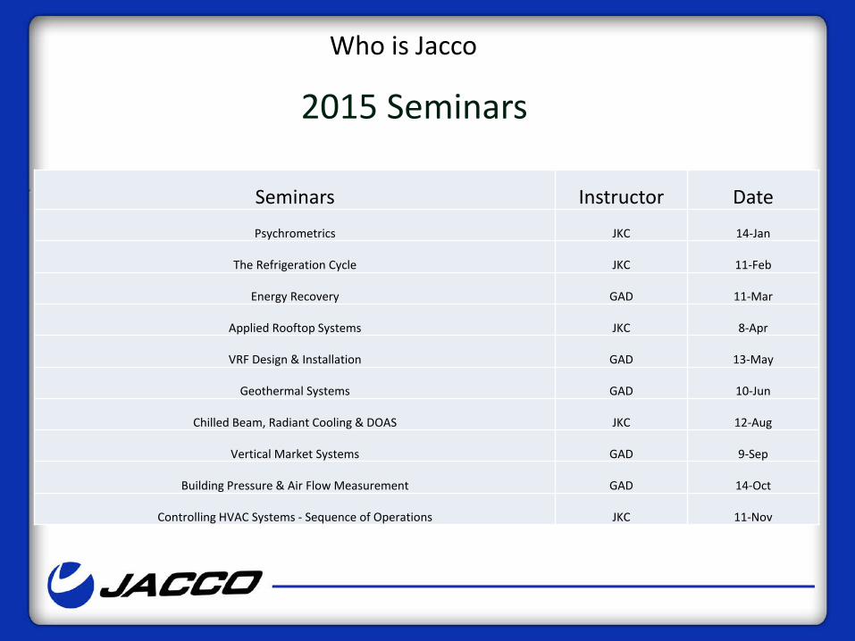
Building Pressure & Air Flow Measurement GAD 14-Oct
Controlling HVAC Systems - Sequence of Operations JKC 11-Nov
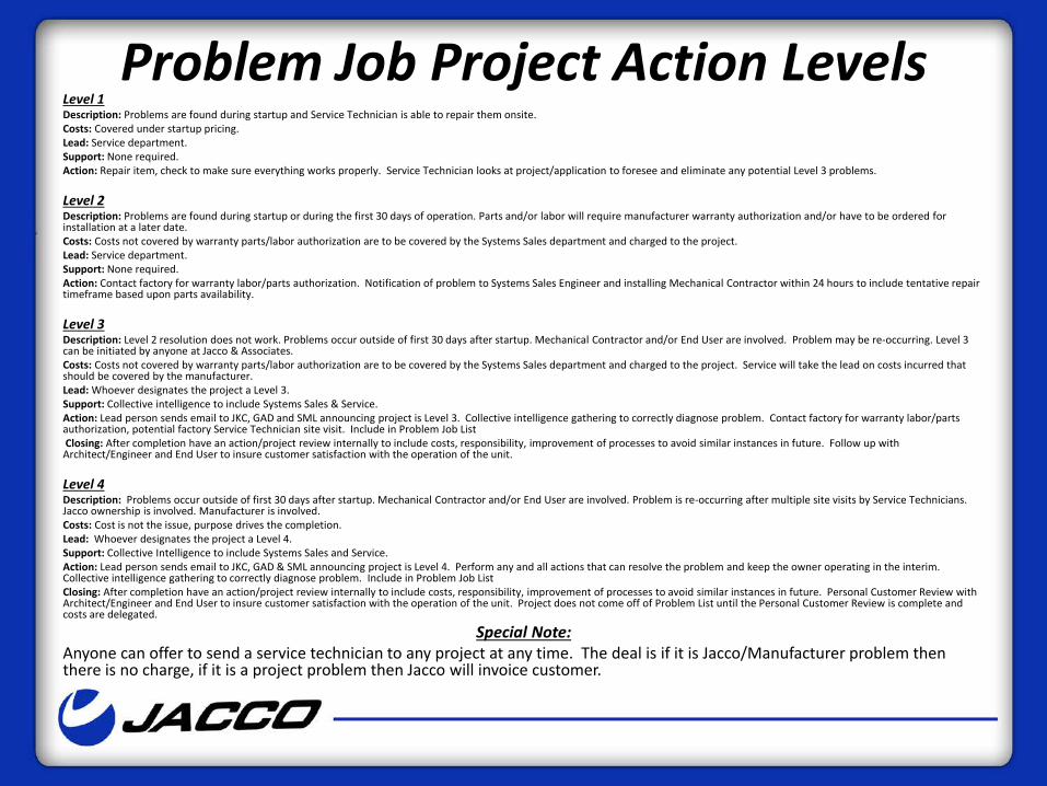
Problem Job Project Action Levels Level 1 Description: Problems are found during startup and Service Technician is able to repair them onsite. Costs: Covered under startup pricing. Lead: Service department. Support: None required. Action: Repair item, check to make sure everything works properly. Service Technician looks at project/application to foresee and eliminate any potential Level 3 problems. Level 2 Description: Problems are found during startup or during the first 30 days of operation. Parts and/or labor will require manufacturer warranty authorization and/or have to be ordered for installation at a later date. Costs: Costs not covered by warranty parts/labor authorization are to be covered by the Systems Sales department and charged to the project. Lead: Service department. Support: None required. Action: Contact factory for warranty labor/parts authorization. Notification of problem to Systems Sales Engineer and installing Mechanical Contractor within 24 hours to include tentative repair timeframe based upon parts availability. Level 3 Description: Level 2 resolution does not work. Problems occur outside of first 30 days after startup. Mechanical Contractor and/or End User are involved. Problem may be re-occurring. Level 3 can be initiated by anyone at Jacco & Associates. Costs: Costs not covered by warranty parts/labor authorization are to be covered by the Systems Sales department and charged to the project. Service will take the lead on costs incurred that should be covered by the manufacturer. Lead: Whoever designates the project a Level 3. Support: Collective intelligence to include Systems Sales & Service. Action: Lead person sends email to JKC, GAD and SML announcing project is Level 3. Collective intelligence gathering to correctly diagnose problem. Contact factory for warranty labor/parts authorization, potential factory Service Technician site visit. Include in Problem Job List Closing: After completion have an action/project review internally to include costs, responsibility, improvement of processes to avoid similar instances in future. Follow up with Architect/Engineer and End User to insure customer satisfaction with the operation of the unit. Level 4 Description: Problems occur outside of first 30 days after startup. Mechanical Contractor and/or End User are involved. Problem is re-occurring after multiple site visits by Service Technicians. Jacco ownership is involved. Manufacturer is involved. Costs: Cost is not the issue, purpose drives the completion. Lead: Whoever designates the project a Level 4. Support: Collective Intelligence to include Systems Sales and Service. Action: Lead person sends email to JKC, GAD & SML announcing project is Level 4. Perform any and all actions that can resolve the problem and keep the owner operating in the interim. Collective intelligence gathering to correctly diagnose problem. Include in Problem Job List Closing: After completion have an action/project review internally to include costs, responsibility, improvement of processes to avoid similar instances in future. Personal Customer Review with Architect/Engineer and End User to insure customer satisfaction with the operation of the unit. Project does not come off of Problem List until the Personal Customer Review is complete and costs are delegated.
Special Note: Anyone can offer to send a service technician to any project at any time. The deal is if it is Jacco/Manufacturer problem then there is no charge, if it is a project problem then Jacco will invoice customer.
Recommendation
• Move the sequence of operations up in the design process.
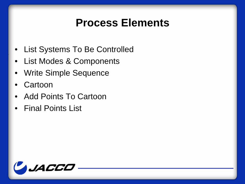
Process Elements
• List Systems To Be Controlled • List Modes & Components • Write Simple Sequence • Cartoon • Add Points To Cartoon • Final Points List
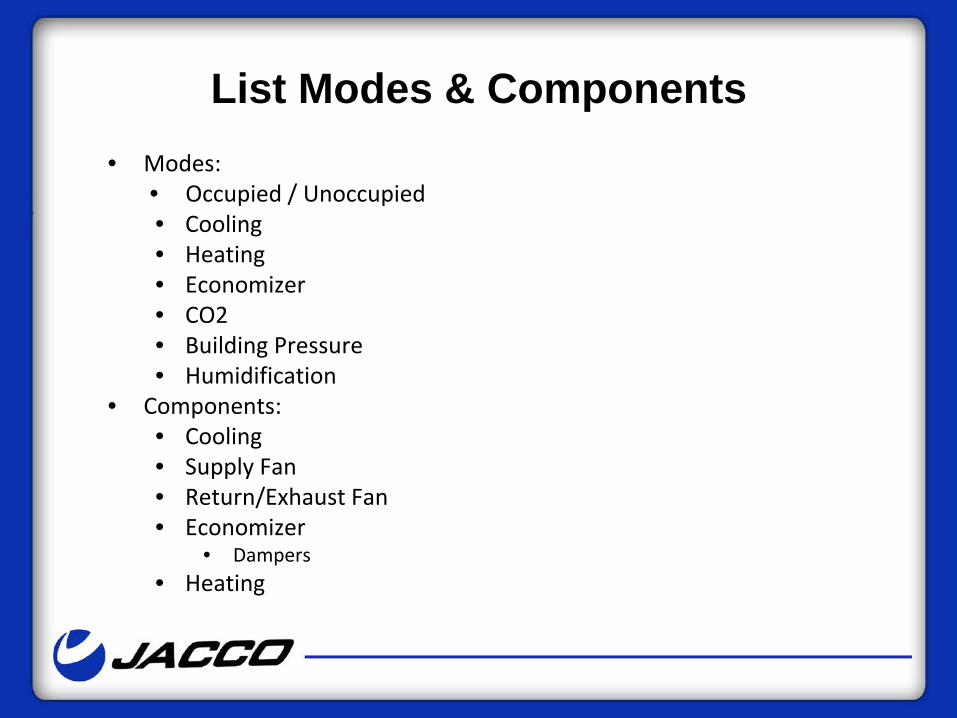
List Modes & Components
• Modes: • Occupied / Unoccupied • Cooling • Heating • Economizer • CO2 • Building Pressure • Humidification
• Components: • Cooling • Supply Fan • Return/Exhaust Fan • Economizer
• Dampers • Heating
List Sub-Components
• Sub-Components: • Cooling
• DX, Chilled Water • Staged, Modulating
• Supply Fan • Constant, Variable
• Return/Exhaust Fans • Constant, Variable • Building Pressure
Your Home • Fan on with call for heating or cooling
– Auto/On • Heating on with call from space thermostat
– Stage as required to maintain 70F adj. – First stage of heating shall be heat pump
• Cooling on with call from space thermostat • Stage as required to maintain 75F adj.
• Humidification on with call from space/return air humidistat – Stage as required to maintain 30% RH adj.
• Unoccupied mode to maintain 55 heating or 85 cooling adj.
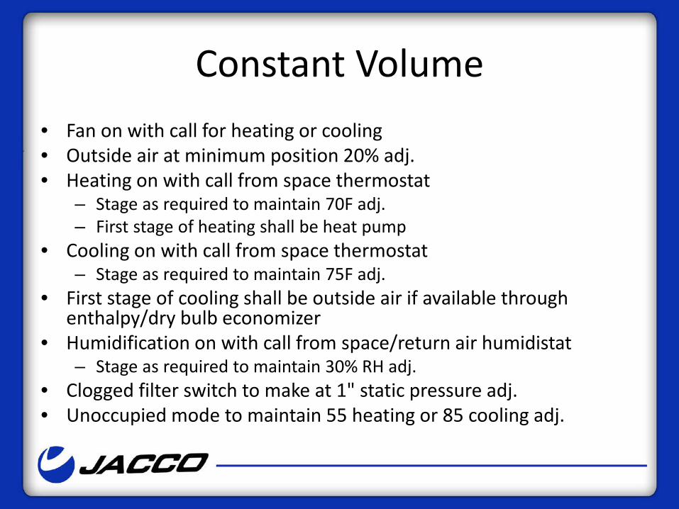
Constant Volume • Fan on with call for heating or cooling • Outside air at minimum position 20% adj. • Heating on with call from space thermostat
– Stage as required to maintain 70F adj. – First stage of heating shall be heat pump
• Cooling on with call from space thermostat – Stage as required to maintain 75F adj.
• First stage of cooling shall be outside air if available through enthalpy/dry bulb economizer
• Humidification on with call from space/return air humidistat – Stage as required to maintain 30% RH adj.
• Clogged filter switch to make at 1" static pressure adj. • Unoccupied mode to maintain 55 heating or 85 cooling adj.
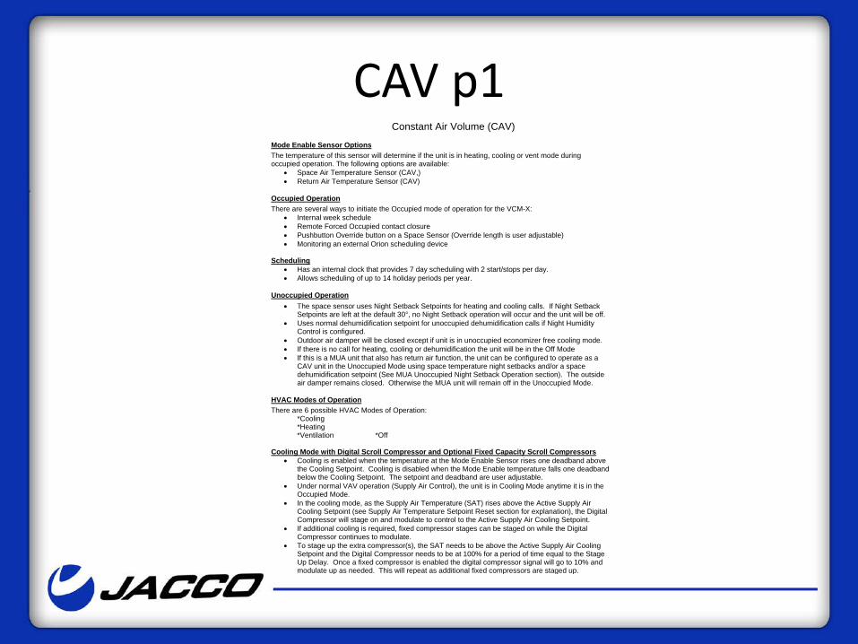
CAV p1 Constant Air Volume (CAV)
Mode Enable Sensor Options The temperature of this sensor will determine if the unit is in heating, cooling or vent mode during occupied operation. The following options are available:
• Space Air Temperature Sensor (CAV,) • Return Air Temperature Sensor (CAV)
Occupied Operation There are several ways to initiate the Occupied mode of operation for the VCM-X:
• Internal week schedule • Remote Forced Occupied contact closure • Pushbutton Override button on a Space Sensor (Override length is user adjustable) • Monitoring an external Orion scheduling device
Scheduling
• Has an internal clock that provides 7 day scheduling with 2 start/stops per day. • Allows scheduling of up to 14 holiday periods per year.
Unoccupied Operation • The space sensor uses Night Setback Setpoints for heating and cooling calls. If Night Setback
Setpoints are left at the default 30°, no Night Setback operation will occur and the unit will be off. • Uses normal dehumidification setpoint for unoccupied dehumidification calls if Night Humidity
Control is configured. • Outdoor air damper will be closed except if unit is in unoccupied economizer free cooling mode. • If there is no call for heating, cooling or dehumidification the unit will be in the Off Mode • If this is a MUA unit that also has return air function, the unit can be configured to operate as a
CAV unit in the Unoccupied Mode using space temperature night setbacks and/or a space dehumidification setpoint (See MUA Unoccupied Night Setback Operation section). The outside air damper remains closed. Otherwise the MUA unit will remain off in the Unoccupied Mode.
HVAC Modes of Operation There are 6 possible HVAC Modes of Operation:
*Cooling *Heating *Ventilation *Off
Cooling Mode with Digital Scroll Compressor and Optional Fixed Capacity Scroll Compressors
• Cooling is enabled when the temperature at the Mode Enable Sensor rises one deadband above the Cooling Setpoint. Cooling is disabled when the Mode Enable temperature falls one deadband below the Cooling Setpoint. The setpoint and deadband are user adjustable.
• Under normal VAV operation (Supply Air Control), the unit is in Cooling Mode anytime it is in the Occupied Mode.
• In the cooling mode, as the Supply Air Temperature (SAT) rises above the Active Supply Air Cooling Setpoint (see Supply Air Temperature Setpoint Reset section for explanation), the Digital Compressor will stage on and modulate to control to the Active Supply Air Cooling Setpoint.
• If additional cooling is required, fixed compressor stages can be staged on while the Digital Compressor continues to modulate.
• To stage up the extra compressor(s), the SAT needs to be above the Active Supply Air Cooling Setpoint and the Digital Compressor needs to be at 100% for a period of time equal to the Stage Up Delay. Once a fixed compressor is enabled the digital compressor signal will go to 10% and modulate up as needed. This will repeat as additional fixed compressors are staged up.
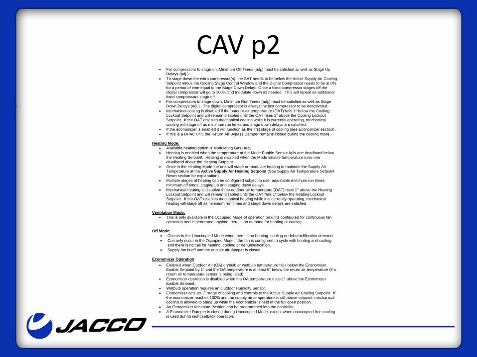
CAV p2 • For compressors to stage on, Minimum Off Times (adj.) must be satisfied as well as Stage Up
Delays (adj.). • To stage down the extra compressor(s), the SAT needs to be below the Active Supply Air Cooling
Setpoint minus the Cooling Stage Control Window and the Digital Compressor needs to be at 0% for a period of time equal to the Stage Down Delay. Once a fixed compressor stages off the digital compressor will go to 100% and modulate down as needed. This will repeat as additional fixed compressors stage off.
• For compressors to stage down, Minimum Run Times (adj.) must be satisfied as well as Stage Down Delays (adj.). The digital compressor is always the last compressor to be deactivated.
• Mechanical cooling is disabled if the outdoor air temperature (OAT) falls 1° below the Cooling Lockout Setpoint and will remain disabled until the OAT rises 1° above the Cooling Lockout Setpoint. If the OAT disables mechanical cooling while it is currently operating, mechanical cooling will stage off as minimum run times and stage down delays are satisfied.
• If the economizer is enabled it will function as the first stage of cooling (see Economizer section). • If this is a DPAC unit, the Return Air Bypass Damper remains closed during the cooling mode.
Heating Mode:
• Available heating option is Modulating Gas Heat. • Heating is enabled when the temperature at the Mode Enable Sensor falls one deadband below
the Heating Setpoint. Heating is disabled when the Mode Enable temperature rises one deadband above the Heating Setpoint.
• Once in the Heating Mode the unit will stage or modulate heating to maintain the Supply Air Temperature at the Active Supply Air Heating Setpoint (See Supply Air Temperature Setpoint Reset section for explanation).
• Multiple stages of heating can be configured subject to user adjustable minimum run times, minimum off times, staging up and staging down delays.
• Mechanical heating is disabled if the outdoor air temperature (OAT) rises 1° above the Heating Lockout Setpoint and will remain disabled until the OAT falls 1° below the Heating Lockout Setpoint. If the OAT disables mechanical heating while it is currently operating, mechanical heating will stage off as minimum run times and stage down delays are satisfied.
Ventilation Mode:
• This is only available in the Occupied Mode of operation on units configured for continuous fan operation and is generated anytime there is no demand for heating or cooling.
Off Mode:
• Occurs in the Unoccupied Mode when there is no heating, cooling or dehumidification demand. • Can only occur in the Occupied Mode if the fan is configured to cycle with heating and cooling
and there is no call for heating, cooling or dehumidification. • Supply fan is off and the outside air damper is closed.
Economizer Operation • Enabled when Outdoor Air (OA) drybulb or wetbulb temperature falls below the Economizer
Enable Setpoint by 1° and the OA temperature is at least 5° below the return air temperature (if a return air temperature sensor is being used).
• Economizer operation is disabled when the OA temperature rises 1° above the Economizer Enable Setpoint.
• Wetbulb operation requires an Outdoor Humidity Sensor. • Economizer acts as 1st stage of cooling and controls to the Active Supply Air Cooling Setpoint. If
the economizer reaches 100% and the supply air temperature is still above setpoint, mechanical cooling is allowed to stage up while the economizer is held at the full open position.
• An Economizer Minimum Position can be programmed into the controller. • A Economizer Damper is closed during Unoccupied Mode, except when unoccupied free cooling
is used during night setback operation.
CAV p3 Space Sensor Operation
• Available as a Plain Sensor, Sensor with Override, Sensor with Setpoint Slide Adjust, and Sensor with Override and Setpoint Slide Adjust.
• Sensors with Setpoint Slide Adjust can be programmed to allow space setpoint adjustment of up to ± 10° F.
• The Setpoint Slide Adjust will adjust the setpoints of whichever sensor is the mode controlling sensor, even if that sensor is not installed Space Temperature Sensor.
• If Space Temperature is being used to reset the Supply Air Temperature Setpoint, then the Slide Adjust will adjust the HVAC Mode Enable setpoints and the SAT/Reset Source setpoints simultaneously.
• For MUA applications the Space Sensor can be used as a reset sensor to reset the Supply Air Setpoint based on space conditions.
• During Unoccupied hours the Override Button can be used to force the unit back into the Occupied Mode (by pressing the button for less than 3 seconds) for a user-defined override duration of up to 8.0 hours. Pressing the button between 3 and 10 seconds cancels the override.
Supply Fan Operation • Occupied Mode – Supply fan can be configured to run continuously (default) or to cycle with
heating, cooling or dehumidification. • Unoccupied Mode – Supply fan will cycle on a call for heating, cooling or dehumidification. • Anytime the Supply Fan is requested to start, a 1 minute minimum off timer must be satisfied. If
the timer is satisfied the Supply Fan relay is activated while all other outputs are held off for a period of 1-2 minutes to purge stagnate air from the ductwork before heating or cooling occurs.
• In fan cycle mode or when going unoccupied the supply fan is held on for 2 minutes after the last stage of heating or cooling stages off.
Dirty Filter Status This input in uses a 24 VAC wet contact closure for Filter Status Indication. A differential pressure switch (by others) is required.
Duct Static Pressure Control for Filter Loading • In order to maintain a constant CFM through the supply air ducts on MUA Unit or a mixed air
CAV, PAC or DPAC Unit, a duct static pressure sensor can be used to monitor the discharge pressure.
• If the filters are getting dirty, the VCM-X will ramp up the VFD to compensate for the decrease in airflow.
• To utilize this feature the unit must be configured to use VFD fan control. • This feature cannot be used if this is a VAV Unit with typical duct static pressure control.
Remote Forced Heating and Cooling • These inputs (24 VAC wet contacts) allow another control system or a thermostat to force the unit
into heating or cooling. • To utilize these inputs, the heating and cooling setpoints in the VCM-X must be set to zero. • Once in this force mode the unit will stage heating/cooling to maintain the appropriate
heating/cooling leaving air setpoint until the force is removed.
Emergency Shutdown • A 24 VAC wet contact input is available to be used with a N.C. Smoke Detector, Firestat, or other
shutdown condition (all by others). • If this contact opens it will initiate shutdown of the VCM-X and will generate an alarm condition.
This contact closure does not produce an instantaneous shutdown.
CAV p4 Temperature Protection:
• Activated when the Supply Air Temperature (SAT) rises above the High Cutoff Temperature (immediate) or drops below the Low Cutoff Temperature (for 10 minutes) both of which are user adjustable. This mode shuts off the unit (with a 3 minute fan off delay) until the mode is cancelled.
• This mode is cancelled when the SAT drops 5 degrees below the High Cutoff Temperature Setpoint or rises 5 degrees above the Low Temp Cutoff Temperature Setpoint, or when the unit changes back into Occupied Operation.
Outdoor Air Lockouts
• Mechanical cooling is disabled when the Outdoor Air Temperature is below the Cooling Lockout Setpoint.
• Mechanical heating is disabled when the Outdoor Air Temperature is above the Heating Lockout Setpoint.
• For Air to Air Heat Pumps the Cooling Lockout also applies to Compressor Heating, so it will usually be a lower setting that on Cooling units that are not Air to Air Heat Pumps.
VCM-X Controller and Expansion Boards I/O Map
I/O Map VCM-X Controller Analog Inputs Analog Outputs Relays 1 Space temperature Economizer Supply Fan 2 Supply Temperature Supply Fan VFD Configurable 3 Return Temperature Configurable 4 Outdoor Temperature Configurable 5 Coil Temperature Configurable 6 Static Pressure 7 Space Sensor Slide Offset or
Remote BAS Reset of SAT Setpoint
VCM-X Expansion Module Analog Inputs Analog Outputs Binary Inputs 1 Outdoor Humidity Building Pressure VFD Emergency Shutdown 2 Space/RA Humidity Modulating Heating Dirty Filter 3 Not Used Modulating Cooling Proof of Flow 4 Building Pressure Return Air Damper Remote Forced Occupied 5 Return Air Bypass Damper Remote Forced Heating 6 Remote Forced Cooling 7 Exhaust Hood On 8 Remote Forced Dehum. 4 Binary Input Expansion Module Binary Inputs 1 Emergency Shutdown 2 Dirty Filter 3 Proof of Flow 4 Remote Forced Occupied 12 Relay Output Expansion Module Relay Outputs 1-12
Configurable
Economizer Operation • Enabled when Outdoor Air (OA) drybulb or wetbulb temperature falls
below the Economizer Enable Setpoint by 1° and the OA temperature is at least 5° below the return air temperature (if a return air temperature sensor is being used).
• Economizer operation is disabled when the OA temperature rises 1° above the Economizer Enable Setpoint.
• Wetbulb operation requires an Outdoor Humidity Sensor. • Economizer acts as 1st stage of cooling and controls to the Active Supply
Air Cooling Setpoint. If the economizer reaches 100% and the supply air temperature is still above setpoint, mechanical cooling is allowed to stage up while the economizer is held at the full open position.
• An Economizer Minimum Position can be programmed into the controller. • Economizer Damper is closed during Unoccupied Mode, except when
unoccupied free cooling is used during night setback operation.
Unoccupied • During the unoccupied mode the fan shall be disabled and the economizer
dampers shall be in the full return position. The unit shall remain in the unoccupied mode until commanded to the warm-up, cool-down, or occupied mode by the building automation system. A call from the VAV boxes shall enable the unoccupied heating or cooling mode.
• During the unoccupied heating mode the supply fan shall be enabled. The economizer dampers shall remain in the full return position. The heat wheel shall remain off and the bypass dampers open. The unit shall cycle the gas heat stages on and off to maintain the unoccupied heating discharge air setpoint of seventy degrees Fahrenheit. The unit shall remain in the unoccupied heating mode for a minimum of fifteen minutes or until all of the VAV boxes have been satisfied. The VAV boxes shall open to 100%
• During the unoccupied cooling mode the supply fan shall be enabled. The economizer dampers shall remain in the full return position, unless outdoor air temperature conditions allow for free cooling. The heat wheel shall remain off and the bypass dampers open. The unit shall cycle the mechanical cooling stages on and off or modulate the economizer dampers to maintain the unoccupied cooling discharge air setpoint of fifty-five degrees Fahrenheit. The unit shall remain in the unoccupied cooling mode for a minimum of fifteen minutes or until all of the VAV boxes have been satisfied. The VAV boxes shall open to 100%
SZVAV • Heating on with call from space thermostat
– Stage as required to maintain 70F adj. • First stage of heating shall be heat pump • Fan at 100% • Outside air at minimum position 20% adj. • Cooling on with call from space thermostat
– Cooling to maintain constant discharge air temperature of 55F adj. – Compressor to modulate
• Fan to modulate to maintain space temperature of 75F adj. • First stage of cooling shall be outside air if available through
enthalpy/dry bulb economizer • Clogged filter switch to make at 1" static pressure adj. • Unoccupied mode to maintain space at 55 heating or 85 cooling
adj.
VAV • Heating and cooling on with call from return air thermostat during
morning start up – Stage as required to achieve 70F adj. return air temperature – Outside air at 0% – Fan at 100% – VAV boxes commanded open to 100%
• Outside air at minimum position 20% adj. • Cooling on year round during occupied mode
– Cooling to maintain constant discharge air temperature of 55F adj. • Compressor to modulate • First stage of cooling shall be outside air if available through enthalpy/dry
bulb economizer • Fan to modulate to maintain duct static pressure of .75" adj. • Clogged filter switch to make at 1" static pressure adj. • Unoccupied mode to maintain space at 55 heating or 85 cooling adj.
VAV Temperature Reset
• The discharge air temperature setpoint shall be reset based on outdoor air temperature. The setpoint shall adjust on a linear scale. – The DAT SP shall be fifty-five degrees Fahrenheit
when the outdoor air temperature is at or above seventy-five degrees Fahrenheit.
– The DAT SP shall be sixty-five degrees Fahrenheit when the outdoor air temperature is at or below forty-five degrees Fahrenheit.
Morning Warm Up • Upon a call from the BAS for morning warm-up the
supply fan shall be enabled to 100%. • Economizer dampers shall remain in the full return
position. • The heat wheel shall remain off and the bypass
dampers open. • The unit shall cycle the gas heat stages on and off to
maintain the return air setpoint of seventy-two degrees Fahrenheit.
• The unit shall remain in the warm-up mode for a minimum of fifteen minutes or until the call for warm-up has been removed
Morning Cool Down • Upon a call from the BAS for morning cool-down the supply
fan shall be enabled to 100%. • The economizer dampers shall remain in the full return
position, unless outdoor air temperature conditions allow for free cooling.
• The heat wheel shall remain off and the bypass dampers open.
• The unit shall cycle the mechanical cooling stages on and off or modulate the economizer dampers to maintain the return air setpoint of seventy-two degrees Fahrenheit.
• The unit shall remain in the cool-down mode for a minimum of fifteen minutes or until the call for cool-down has been removed
Single Duct VAV Boxes Single Duct Cooling Only • With room temperature at setpoint, unit delivers minimum cfm. An increase in room
temperature causes airflow to increase. Airflow and temperature setpoints can be different for Occupied, Unoccupied, and Night Setback states.
Cooling with Electric Reheat • An increase in room temperature over cooling setpoint causes airflow to increase. Below
cooling setpoint, airflow is at minimum or zero. A decrease in room temperature below heating setpoint causes airflow to increase to the second heating minimum, as stages of reheat are energized. Airflow and temperature setpoints can be different for Occupied, Unoccupied, and Night Setback states.
Cooling with Proportional Hot Water Reheat • An increase in room temperature over cooling setpoint causes airflow to increase. Below
cooling setpoint, airflow is at minimum or zero. A decrease in room temperature below heating setpoint causes airflow to increase to a fixed heating minimum, or modulate to match water valve action, as hot water valve modulates open. Airflow and temperature setpoints can be different for Occupied, Unoccupied, and Night Setback states.
Series Fan Powered VAV Boxes Constant Fan VAV Terminal Cooling Only • Fan operates continuously in Occupied mode, providing constant volume to the space. An
increase in room temperature causes cooling airflow to increase. Airflow and temperature setpoints can be different for Occupied, Unoccupied, and Night Setback states for all Constant Fan VAV Terminal sequences.
Constant Fan VAV Terminal with Electric Heat • Fan operates continuously in Occupied mode, providing constant volume to the space. An
increase in room temperature triggers an increase in cooling airflow. Below cooling setpoint, cooling airflow is at minimum or zero. On a decrease in room temperature below heating setpoint, stages of heat are energized.
Constant Fan VAV Terminal with Proportional Water Heat • Fan operates continuously in Occupied mode, providing constant volume to the space. An
increase in room temperature causes cooling airflow to increase. Below cooling setpoint, cooling airflow is at minimum or zero. On a decrease in room temperature below heating setpoint hot water valve modulates open.
Parallel Fan Powered VAV Boxes Variable Volume Fan VAV Terminal Cooling Only • At cooling setpoint, unit delivers minimum cooling cfm. An increase in room temperature
causes cooling airflow to increase. On a decrease in room temperature below heating setpoint or on a decrease in cooling cfm approaching cooling setpoint (software selectable), unit fan is energized to provide plenum air to the space. Airflow and temperature setpoints can be different for Occupied, Unoccupied, and Night Setback states, for all variable volume fan VAV terminal sequences.
Variable Volume Fan VAV Terminal with Electric Heat • At cooling setpoint, unit delivers minimum cooling cfm. An increase in room temperature
causes cooling airflow to increase. On a decrease in room temperature below heating setpoint or on a decrease in cooling cfm approaching cooling setpoint (software selectable), unit fan is energized to provide plenum air to the space, and stages of heat are energized.
Variable Volume Fan VAV Terminal with Proportional Water Heat • At cooling setpoint, unit delivers minimum cooling cfm. An increase in room temperature
causes cooling airflow to increase. On a decrease in room temperature below heating setpoint or on a decrease in cooling cfm approaching cooling setpoint (software selectable), unit fan is energized to provide plenum air to the space, and hot water valve modulates open.
VVT • Heating on with call from space thermostat (polling or largest offset or designated
thermostat) – Modulate/stage heat to maintain 85F discharge air adj. – 4 stage to 10:1 modulation with gas heat – First stage of heating shall be heat pump
• Fan to modulate to maintain duct static pressure of .75" adj. • Outside air at minimum position 20% adj. • Cooling on with call from space thermostat (polling or largest offset or designated
thermostat) – Cooling to maintain constant discharge air temperature of 55F adj. – Compressor to modulate
• Fan to modulate to maintain duct static pressure of .75" adj. • First stage of cooling shall be outside air if available through enthalpy/dry bulb
economizer • No call from space, cooling and heating off, fan to modulate return air to maintain
duct static pressure of .75" adj. • Clogged filter switch to make at 1" static pressure adj. • Unoccupied mode to maintain space at 55 heating or 85 cooling adj.
DOAS • Heating on with call from outdoor air thermostat at 65F adj. • Modulate heat to maintain 70F adj. • First stage of heating shall be heat pump • OA & RA dampers at 100% • Supply and exhaust fan at 100% • Cooling on with call from outdoor air thermostat at 75F adj.
or DP of 50F adj. • Cooling to maintain constant discharge air dewpoint of 50F
adj. – Compressor to modulate – Hot gas reheat to maintain discharge air at 75F adj.
• Heat wheel shall be on during heating and cooling modes • Clogged filter switch to make at 1" static pressure
Heat Wheel • Wheel shall be on during heating and cooling modes • Wheel shall be protected from defrost by preheat, VFD
or OA bypass • The heat wheel shall act as first stage heating or
cooling. • The heat wheel shall be locked out when the outdoor
air temperature is between fifty-five and seventy-five degrees Fahrenheit. – Two bypass dampers, one for outdoor air and one for
exhaust air, shall open when the heat wheel is locked out. – The exhaust fan shall be enabled when the heat wheel is
enabled.
Space Temperature & Humidity
• Dehumidification to initiate based on 50F dew point room adj.
• At low loads simultaneous heat maybe required to maintain set point
• Modulating hot gas reheat controlled by room thermostat
• Return air bypass damper controlled by room thermostat?
Dehumidification Mode with a Digital Scroll Compressor And Optional Fixed Compressor
• In MUA applications dehumidification is enabled based on an Outdoor Air Dewpoint Setpoint. This requires an Outdoor Humidity and Outdoor Temperature sensor.
• Dehumidification can be selected as a priority mode to be active anytime the humidity is above the Indoor Humidity Setpoint, otherwise it is only available when heating and cooling demands are satisfied (Vent Mode).
• Once in dehumidification, the unit will maintain the Evaporator Coil Suction Temperature at the Coil Suction Temperature Setpoint by modulating the Digital Compressor.
• A coil suction pressure sensor is required and is typically factory installed. • If additional dehumidification is required, fixed compressor stage(s) can be staged on. Once fixed compressor(s) are
activated the Digital Compressor will only be allowed to modulate down to 70% in order to maintain reheat capacity. • To stage up the extra compressor(s), the Evaporator Coil Suction Temperature needs to be above the Evaporator Coil Suction
Temperature Setpoint and the Digital Compressor needs to be at 100% for a period of time equal to the Stage Up Delay. Once a fixed compressor is enabled the digital compressor signal will go to 70% and modulate up as needed. This will repeat as additional fixed compressors are staged up.
• To stage down the extra compressor(s), minimum runs times must be met, the Evaporator Coil Suction Temperature needs to be below the Evaporator Coil Suction Temperature Setpoint minus the Cooling Stage Control Window, and the Digital Compressor needs to be at 70% for a period of time equal to the Stage Down Delay. Once a fixed compressor stages off, the digital compressor will go to 100% and modulate down as needed to maintain the coil temperature setpoint. This will repeat as additional fixed compressors stage off. The digital compressor is always the last compressor to be deactivated.
• Dehumidification Reheat is always controlled to the appropriate Active Supply Air Temperature Setpoint which will be dependent on whether you are in Heating Dehumidification, Cooling Dehumidification, or Vent Dehumidification. During Vent Mode Dehumidification the Supply Air Temperature Setpoint is calculated to be halfway between the HVAC Mode Setpoints.
• Reheat options are modulating or fixed hot gas reheat, field wired downstream duct heat, and, in certain applications, unit heat.
• Heating may also be used to supplement hot gas reheat if necessary. In this case, one form of modulating SCR Electric or Modulating HW heat or 1 stage of gas or electric heat may be used.
• WARNING: Using simultaneous heating and cooling cannot be approved unless the HVAC unit has been specifically designed for this purpose.
Coil Suction Temperature Setpoint Reset
• During dehumidification automatically reset the Coil Suction Temperature Setpoint within a ± 5° range based on the space or return air humidity sensor condition rising or falling with a ± 5 % range.
MAU w/o Humidity Control • Heating on with call from outdoor air thermostat at 65F adj.
– Modulate heat to maintain 85F adj. • First stage of heating shall be heat pump • Outside air at 100% • Supply fan at 100% • Cooling on with call from outdoor air thermostat at 75F adj. • Cooling to maintain constant discharge air temperature of
55F adj. – Compressor to modulate
• Room thermostat to reset heating and cooling discharge air temperature as required to maintain space temperature
• Clogged filter switch to make at 1" static pressure
MAU w/ Humidity Control • Heating on with call from outdoor air thermostat at 65F adj.
– Modulate heat to maintain 85F adj. • First stage of heating shall be heat pump • Outside air at 100% • Supply fan at 100% • Cooling on with call from outdoor air thermostat at 75F adj. • Cooling to maintain constant dewpoint temperature of 55F adj.
– Compressor to modulate – Room thermostat to activate modulating hot gas reheat to maintain
space temperature • Room thermostat to reset heating discharge air temperature as
required to maintain space temperature • Clogged filter switch to make at 1" static pressure
Low Limit
• The unit shall be shutdown if the discharge air temperature falls below the low limit set point of 45F adj.
• Low Limit or Freezestat?
GEO/WSHP
• Start pump or pump run continuously • Proof of flow • When loop temperature falls below 60F adj.
allow heat injection • When loop temperature rises above 90F allow
heat rejection
VRF • You Don’t Have a Choice…
• Nice things we have seen!
– Alternating Defrost!!! – Snow Blow Function – Lead/Lag/Alternating Compressor!!! – Space or RA Sensor Selection – # of Fan Coils per Sensor
• Make Sure Manufacturer Software is Left on the Job!
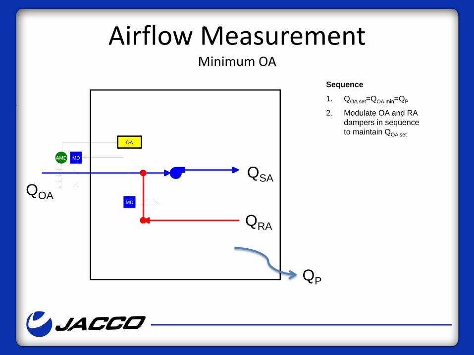
Airflow Measurement Minimum OA
OA
AMD
MD
MD
QOA QSA
QRA
QP
Sequence
1. QOA set=QOA min=QP
2. Modulate OA and RA dampers in sequence to maintain QOA set
OA
AMD
MD
MD
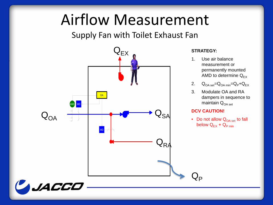
STRATEGY:
1. Use air balance measurement or permanently mounted AMD to determine QEX
2. QOA set=QOA min=QP+QEX
3. Modulate OA and RA dampers in sequence to maintain QOA set
DCV CAUTION!
• Do not allow QOA set to fall below QEX + QP min
QOA QSA
QRA
QEX
QP
Airflow Measurement Supply Fan with Toilet Exhaust Fan
Airflow Measurement Supply/Exhaust Fan System, Minimum OA
OA
AMD
MD
MD
QOA QSA
QRA
QP
AMD
QP
QRE
Sequence:
1. QOA set=QOA min
2. Modulate OA and RA dampers in sequence to maintain QOA set.
3. QRE set= QOA-QP
4. Modulate relief fan to maintain QRE set
OA
AMD
MD
MD
QP
AMD
AMD2
Pos
OPEN
STRATEGY:
1. QOA set=QOA min
2. Modulate OA and RA dampers in sequence to maintain QOA set
3. Use air balance measurement or permanently mounted AMD to determine QEX
4. QRA set=QSA-(QP+QEX)
5. Modulate exhaust fan to maintain QRA set
DCV CAUTION!
• Do not allow QOA set to fall below QEX + QP min
QP
QOA QSA
QRA
QEX
QRE
Airflow Measurement Supply/Exhaust Fan System, Bldg. Pressure
OA
AMD
MD
MD
STRATEGY:
1. Use air balance measurement or permanently mounted AMD to determine QEX
2. QOA set=QOA min=QP+QEX
3. Modulate OA damper, RA fan and RA damper in sequence to maintain QOA set
DCV CAUTION!
• Do not allow QOA set to fall below QEX + QP min
QOA QSA
QRA
QEX
QP
Airflow Measurement Supply/Return Fan System, Minimum OA
STRATEGY:
1. QOA set=QOA min
2. Modulate OA and RA dampers in sequence to maintain QOA set
3. Use air balance measurement or permanently mounted AMD to determine QEX
4. QRA set=QSA-(QP+QEX)
5. Modulate return fan to maintain QRA set
6. OPTION: Modulate or open relief damper to maintain slight positive bleed airflow or pressure.
DCV CAUTION!
• Do not allow QOA set to fall below QEX + QP min
OA
AMD
MD
MD
QP
AMD
AMD2
Pos
OPEN
BS
Optional
QOA QSA
QRA
QEX
QRE
QP
Airflow Measurement Supply/Return Fan System, Bldg. Pressure
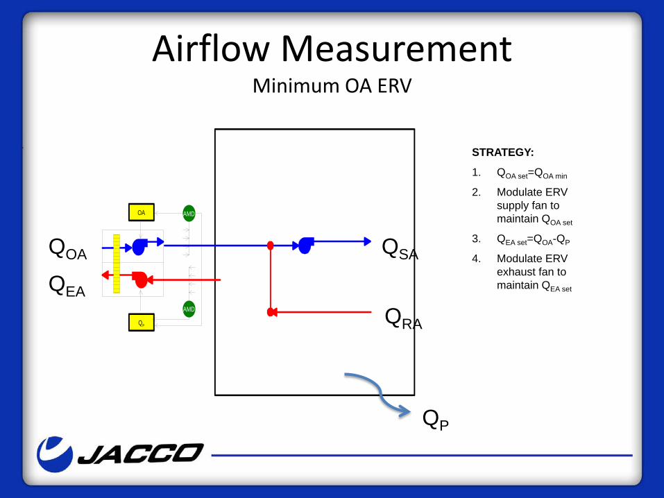
STRATEGY:
1. QOA set=QOA min
2. Modulate ERV supply fan to maintain QOA set
3. QEA set=QOA-QP
4. Modulate ERV exhaust fan to maintain QEA set
AMD
AMDOA
QP
QP
QOA QSA
QRA QEA
Airflow Measurement Minimum OA ERV
Airflow Measurement Minimum OA ERV - Multiple AHU’s – Low or High-rise
MD
MD
SPOAFan
OA2
AMD
AMD
OA1
MD
MD
QP1
SP
QP2
EX Fan
AMD
AMD
STRATEGY:
1. Modulate ERV SA and EA fans to maintain static pressure setpoint of outdoor air and exhaust air ducts
2. QOA1set=QOA1min
3. Modulate zone outdoor air damper to maintain QOA1set
4. QEA1set=QOA1-QP1
5. Modulate zone exhaust air damper to maintain QEA1set
6. DO FOR ALL ZONES SERVED
STRATEGY:
1. Modulate SA and RA (or RE) fans to maintain duct static (w/reset)
2. QOA set=QOA min
3. Modulate OA and RA dampers in sequence to maintain QOA set
4. QRA1set=QSA1-(QP1+QEX1)
5. Modulate floor/zone return damper to maintain QRA1set
6. DO FOR ALL FLOORS OR PRESSURE ZONES SERVED
7. OPTION: Modulate or open relief damper to maintain slight positive bleed airflow or pressure.
SPSA Fan
AMD
AMD
MD
MD
QP1
QP2
OA
AMD
MD
MD AMD
AMD
SPRA Fan
2 Pos
OPEN
BS
Recommended
QP1
QSA1
QRA1
QEX1
QOA
QRE
Airflow Measurement Single Supply/Return/Exhaust - Multiple Floors – High-rise
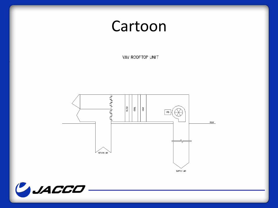
Cartoon
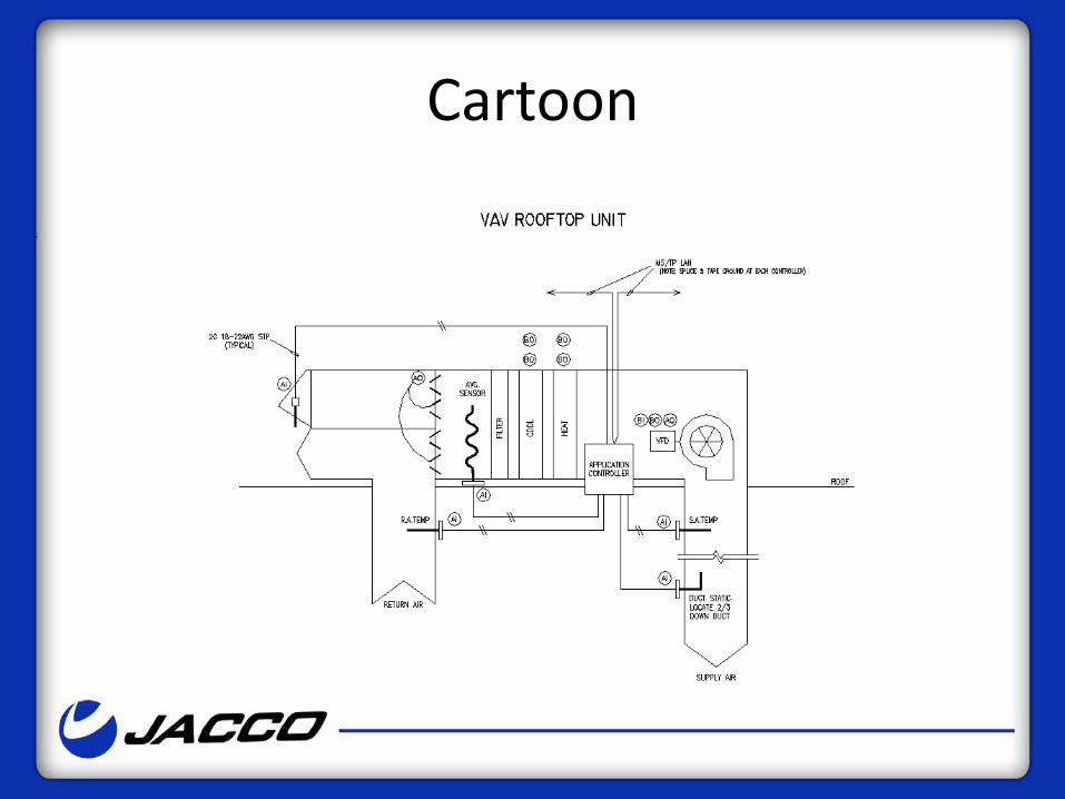
Cartoon
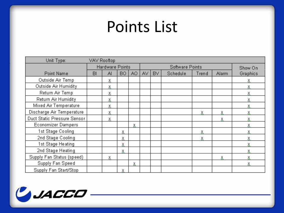
Points List
Alarming
• The BAS shall generate alarms for the following items: – Low limit shutdown – Clogged filter alarm – Supply fan failure – Exhaust fan failure – High Temperature in Cooling – Low Temperature in Heating
Problem Job
• MAU with heat pump and heat recovery • Unit set up for SZVAV. • Building pressure was introduced and the
exhaust fan was shut off and the supply fan was running at 100%.
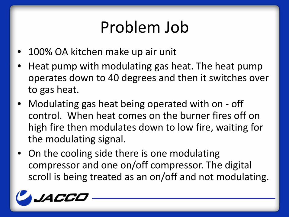
Problem Job • 100% OA kitchen make up air unit • Heat pump with modulating gas heat. The heat pump
operates down to 40 degrees and then it switches over to gas heat.
• Modulating gas heat being operated with on - off control. When heat comes on the burner fires off on high fire then modulates down to low fire, waiting for the modulating signal.
• On the cooling side there is one modulating compressor and one on/off compressor. The digital scroll is being treated as an on/off and not modulating.
Problem Job
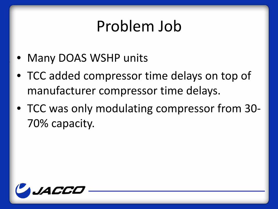
• Many DOAS WSHP units • TCC added compressor time delays on top of
manufacturer compressor time delays. • TCC was only modulating compressor from 30-
70% capacity.
Recommendations • If controls by TCC…Always provide the
sequence to the manufacturer’s rep for review and approval.
• If controls by TCC…SLOW DOWN!!! • Don’t mix and match control systems on the
same unit. • Go with factory controls when possible, they
have invested the time and money to get their sequence to work.
Recommendation
• Move the sequence of operations up in the design process.
• Visit our website, we have posted detailed sequence of operations in the Engineering Tools tab which can be found under the HVAC Systems tab.
Your Home • Fan on with call for heating or cooling • Heating on with call from space thermostat Stage as
required to maintain 75F adj. • First stage of heating shall be heat pump Cooling on
with call from space thermostat Stage as required to maintain 70F adj.
• Humidification on with call from space/return air thermostat Stage as required to maintain 30% RH adj.
• Unoccupied mode to maintain 55 heating or 85 cooling adj.