86
| Date post: | 30-Mar-2019 |
| Category: |
Documents |
| Upload: | truongthien |
| View: | 276 times |
| Download: | 12 times |


Z80™MICROCOMPUTER SYSTEN\
EUROCRATIC MOS
Since setting up its MaS department in 1966, SGS-ATES has led the way inEuropean MaS technology.
Between the major landmarks of the first European-designed MaS calculator in1968 and the F8 microprocessor in 1977, we brought you a full range of memories:1K static and 4K dynamic RAMs, a lK x 8 EPROM, a 2K x 8 ROM .....and now we bring you the Z-80.
Not only the Z-80 but a team of experts dedicated to the development of theZ-80 device family, Z-80 systems, applications and interface devices.
Moreover, we've set up a comprehensive European network of "local" microcomputer application centres packed with the most up-to-date equipment available,staffed with highly-experienced software engineers and located in UK, Sweden, Italy,France and Germany.
SGS-ATES and Zilog: a vast reserve of know-how and resources committed tothe advancement of microprocessors - stay with us and be part of the Z-80 conquest.
TM: zao is a registered trademark of Zilog, Inc.

CONTENTS
The Z80 MicrocomputerThe Z80-CPU/Z80A-·CPUThe Z80-PIO/Z80A-PIOThe Z80-CTC/Z80A-CTCThe Z80-DMA/Z80A-DMAThe Z80-SIO/Z80A-SIOThe Z80-SI09/Z80A-SI09The Z80-DART/Z80A-DART
PRODUCT LINE. .CENTRAL PROCESSING Ul\IT .PARALLEL INPUT/OUTPUT. .COUNTER TIMER CIRCUIT. .DIRECT MEMORY ACCESS CONTROLLER.SERIAL INPUT/OUTPUT .SERIAL INPUT/OUTPUT . . . . . . . .DUAL ASYNCHRONOUS RECEIVER/TRANSMITTER
PagL~
1-45-14
15-2425-3435-5051-6667-69
. 71-81

Z-80 MICROCOMPUTER PRODUCT LINE
IntroductionThe l-80 LSI component set includes all
of the logic circuits necessary for the user to(mild high performance microcomputer systemswith virtually no external logic and an absoluteminimum number of lowest cost standard memory components. The l-80 component set isbacked by advanced software, a disk basedhardware/software development system andcomplete training and support. The entire l-80product line has been developed as a single,highly integrated entity to insure that the usercan develop his system qUickly and still obtainall the performance advantages of the l-80component set.
High System ThroughputThe architecture of the l-80 CPU includes
a superset of 158 instructions, with moreinternal registers and addressing modes thansecond generation microcomputers and extremely fast interrupt response time. All of thesefeatures mean that in any given amount of timethe l-80 can perform far more work (processorthroughput) than any other micro-computersystem available today. This throughput advantage allows users to continually expand thefeatures and capab,ilities of their systems with ..out increasing hardware costs.
Low Memory CostsOne of the major features of the l-80
CPU is that it greatly reduces system memorycosts. The expanded set of 158 software instructions results in a tremendous reduction in thememory required for any typical application. Inaddition, the l-80 CPU provides all refresh andtiming signals to directly drive dynamic memories so that the l-80 LSI components can interface to most standard 4K dynamic memorieswith virtually no external logic. The l-80 CPUuses a technique whereby the memory addressis generated very early in memory cycles, permitting the high speed l-80 CPU to operatewith standard speed memories, again reducingsystem memory costs. The l-80 CPU wasdesign~d to operate with standard memoryproducts from any source since these deviceswill always be less expensive than custom memories designed for any particular microcomputer.
Low I/O CostsThe l-80 LSI component set includes
four general purpose programmable I/O circuitsthat contain all of the logic required to imple··ment fast I/O transfers with minimal CPU overhead. These circuits have a built-in ripple priorityinterrupt control circuit (the device closest tothe CPU has the highest priority) and all thelogic necessary for nesting of interrupts to anylevel. Using the programmable features of thesecircuits, the user can configure the devices tointerface with a wide range of peripheral deviceswith virtually no other external logic. Thesefeatures make the peripheral device controllersin a l-80 system much simpler and thereforelower in cost.
Low System Hardware CostsThe l-80 component set requires very
little support circuitry. All devices require asingle +5 volt power supply and, a single phaseTTL clock. In addition, all control signals aredirectly compatible with I/O and memorydevices so that system control circuits are notreqUired. External interrupt control circuits arenot required since these are included in everyl-80 I/O circuit. DMA circuits are generally notrequired due to an extremely fast interruptresponse and powerful I/O block transfercapability within the CPU.
Low Development CostsSGS-ATES offers more than a fully
integrated line of LSI components. Everythingis provided that is necessary for the user toeasily develop his own proprietary system usingthe l-80 components. This includes completesoftware packages, disk based developmentsystems and training. For example, the expandedl-80 software instruction set coupled with theeasy to learn l-80 assembly language andreference cards make assembly language programming much easier than previously possible.For larger programs, PL/l may be used tospeed up the development cycle, to enhanceprogram documentation and to improve programmaintainability.

Z-80 MICROCOMPUTER SUMMARY
Central Processor Unit/Z-80-CPUo Single chip, N-channel processoro 158 instructions - Includes all 78 of the
8080A instructions with total software com·patibility. New instructions include 4-, 8and 16-bit operations with more usefuladdressing modes.
D 17 internal registers (more than twice the8080A registers), including two real indexregisters.
D Three modes of fast interrupt response plusa nonmaskable interrupt.
D Directly interfaces standard speed static ordynamic memories with virtually no externallogic.
D 1.6J.Ls instruction execution speed.D Single 5V supply and single-phase TTL Clock.D Out-performs any other microcomputer in 4-
4-,8-, 16-bit applications.D Requires 25% to 50% less memory space
than the 8080A CPU.D Up to 500% more throUgllput than the
8080A.D TTL compatible tri-state data and address
busses.
Interface and Control CircuitsParallel Input/Output Controller/Z-80-PIO
Programmable circuit that allows for adirect interface to a wide range of parallel interface peripherals without other external logic.
Serial Input/Output Controller/Z-80-SIOProgrammable circuit that allows for a
direct interface to a wide range of serial interface peripherals without other external logic.
Counter Timer Circuit/Z-80-CTCContains four independent programmable
counter timer circuits for control of real tim~
events.
Direct Memory Access Controller/Z-80-DMAProgrammable circuit that can directly
transfer data between the SIO or Pia andmemory on a CPU cycle steal basis ..
All 2-80 controllers have built in nestedpriority interrupt control and fast interruptresponse capability (up to 6 times faster thanthe 8080A).
All 2-80 controllers monitor peripheralstatus to eliminate any type of CPU polling.
2

Z-80 COMPONENTSIntroduction
The SGS-ATES third generation microcomputer components are the most advancedand comprehensive set of LSI microcomputerproducts available today. The major components in the l-80 product line are an extremelyhigh performance central processing unit (CPU),a programmable parallel input/output controller(PIO), a programmable serial input/output controller (SIO), a versatile counter timer circuit(CTC) and a high speed direct memory accesscontroller (DMA).
All of the l-80 components utilize theindustry standard N-channel silicon gate technology to provide the highest density at thelowest cost. Depletion load technology is alsoused to provide high performance with a single5V power supply.
The CPU, PIO, SIO and DMA are packages in standard 40-pin DIPs; the CTC comes in astandard 28-pin DIP. All require only a single5V power supply plus the l-80 single-phaseTTL level clock.
Z-80 CPUThe l-80 CPU is an extremely powerful,
third generation CPU which incorporates anumber of major features over the standard8080A CPU while retaining total softwarecompatibility. Major improvements include:o More than twice as many registers on theCPU chip, including two real index registerso Many more addressing modes 0 More thantwice as many instructions 0 Three modes ofextremely fast interrupt response 0 A separatenon-maskable interrupt to a fixed location.
Another unique feature of the l-80 CPUis its ability to generate all of the control signalsfor standard memory circuits. Static memoriescan be interfaced using only an external addressdecoder for chip selects. In addition the l-80CPU provides all of the refresh control fordynamic memories, and the l-80 control bustiming signals are directly compatible with allwidely used, standard speed, 18- and 22-pin4K RAMs (16-pin 4K RAMs require only anexternal address multiplexer). Thus dynamicRAMs can be interfaced with virtually noadditional external logic. This provides the userwith the ability to easily interfa~e to the lowestcost dynamic memories without reducing CPUoperational speed.
By selecting the best standard memory fora given application, the user can reduce hisproduct manufacturing costs, and the productdevelopment expenses will also be much lower.
The l-80 CPU is designed to be totallysoftware compatible with the standard 8080Amicroprocessor to facilitate the user's transitionto the l-80. By using the l-80 component setand the most economical memory for theparticular application, the user need only relayout any 8080 based design and use any existing software programs to obtain an immediateand very significant reduction in system hardware costs. A major advantage is that the sameROMs that are used in the 8080 system can beused in the l-80 system. At a later date the software programs can be upgraded, taking advantage of the powerful l·80 instruction set andthe full capability of the l-80 component set toobtain increased performance and even furthercost reduction for memory components.
The l-80 CPU is an extremely fast andversatile device. Full instruction cycle times fornon-memory reference instructions are 1.6.usand the CPU responds to interrupts very rapidly(the 8080 requires up to 6 times as long torespond, and uses more than twice as muchmemory storage). This fast interrupt response,in conjunction with new I/O block transferinstructions, allows the CPU to directly controlmany peripherals without the costly use ofDMA hardware and it greatly reduces the sizeof software routines required for peripheralcontrol, again saving memory space and costs.
Probably the most important feature ofthe l·80 microprocessor family is its repertoireof 158 software instructions. The original 78instructions of the 8080A CPU are includedusing the same OP codes; thus, the l-80 canexecute 8080 or 8080A programs stored inexisting ROMs. The l-80 new software instructions provide an expanded capability for theuser, such as: 0 Additional addressing modes,including indexed and relative LJ Memory tomemory block transfers and searches D Bitmanipulation and testing in any register ormemory location D Many new I/O instructions,including block I/O transfers 0 A wide range ofmemory or register rotates and shifts (logicaland arithmetic) 0 Expanded 16-bit arithmetico Expanded BCD arithmetic.
3

Parallel Input/Output (PIO)The Z·80 PIO circuit uses an advanced
interrupt driven,program controlled I/O transfertechnique for easy handling of virtually anyperipheral with a parallel interface. Withoutother logic, the PIO can interface most lineprinters, paper tape readers or punchers, cardreaders, keyboards, electronic typewriters andother similar devices.
The PIO contains all of the interruptcontrol logic necessary for nested priorityinterrupt handling with very fast response time.Thus additional interrupt control circuits arenot needed and servicing time is minimized.The parallel I/O can handle two high speed I/Oports, and it interrupts the CPU after each I/Otransfer is complete.
The PIO circuit include two independentports, each with eight I/O lines and two hand·shake lines which are programmed by the CPUto operate in one of four modes: 0 Byteoutput with interrupt driven handshake 0 Byteinput with interrupt driven handshake 0 Bidi·rectional byte bus with interrupt driven hand·shake 0 Control mode wherein any bit can beprogrammed as an input or output.
A major feature of the PIO is its ability togenerate an interrupt on any bit pattern at theI/O pins, thus eliminating the need for theprocessor to constantly test I/O lines for a par·ticular peripheral status condition. This featuregreatly enhances the ability of the processor toeasily handle peripherals, while also reducingsoftware overhead.
Serial Input/Output (SIO)The SIO circuit is a programmable I/O
device similar in concept to the PIO, exceptthat it is designed to handle peripherals with aserial data interface such as floppy disks, CRTsand communication terminals. Each SIO circuitcan handle a full duplex serial I/O channel. Thedevice will handle data that is asynchronouswith 5· to 8·bit characters and with I, 11 or 2stop bits. The SIO will handle 5· to 8·bit syn·chronous data including IBM BiSync and SDLcommunication channels. CRC generation andparity checking are also included.
4
Counter Timer Circuit (CTC)The CTC circuit contains four versatile
clocks, each with its own nested priorityinterrupt control. All clocks have a minimumresolution of 8/ls and can generate interrupts inthe range of 8/ls to 32 ms. The circuit may alsobe used in a mode in which it counts externalevents. Another major feature is that aninterrupt can be programmed to occur after theoccurrence of an external event. The four tim·ing circuits greatly ease the CPU software handling requirements for many real-time controlapplications. For example, the CTC allows theimplementation of a very low·cost TTY or CRTI/O port, and simple sector control of floppydisk subsystems.
Direct Memory Access Controller (DMA)The DMA circuit is provided for those
applications in which data must be transferreddirectly into memory at a very high rate ratherthan going through the central processor unit.This circuit is not needed for most applicationsdue to the fast interrupt response and blocktransfer capabilities of the Z-80 CPU. However,in large systems applications with many highspeed peripherals, such as floppy disks, communications channels, etc., the DMA circuit cangreatly improve system performance by totallycontrolling block transfers between I/O circuitsand the system memory.
The DMA circuit contains all control forfour I/O circuits including a block lengthcounter and a memory address pointer. Thecircuits also have a ripple priority chain so thatvirtually any number of DMA channels can beimplemented. The DMA circuit communicatesdirectly between the I/O circuits and thesystem memory after obtaining a DMA acknowledge signal from the CPU.

MUSINTEGRATEDCIRCUITS
The SGS-ATES Z80 product line is a complete set ofmicrocomputer components, development systems and supportsoftware. The Z80 microcomputer component set includesall of the circuits necessary to build high-performancemicrocomputer systems with virtually no other logic and aminimum number of low cost standard memory elements.
The Z80 and Z80A CPU's are third generation single chiImicroprocessors with unrivaled computational power. Thisincreased computational power results in higher systemthrough-put and more efficient memory utilization whencompared to second generation microprocessors. Inaddition, the Z80 and Z80A CPU's are very easy to implement into a system because of their single voltage requirement plus all output signals are fully decoded and timed tocontrol standard memory or peripheral circuits. The circuitis implemented using an N-channel, ion implanted, silicongate MOS process.
Figure I is a block diagram of the CPU, Figure 2 detailsthe internal register configuration which contains 208 bitsof Read/Write memory that are accessible to the programmer. The registers include two sets of six general purposeregisters that may be used individually as 8-bit registers 01
as 16-bit register pairs. There are also two sets of accumulator and flag registers. The programmer has access to eitherset of main or alternate registers through a group of exchange instructions. This alternate set allows foreground/background mode of operation or may be reserved for veryfast Interrupt response. Each CPU also contains a 16-bitstack pointer which permits simple implementation of
Fig. 1[- ZSO, ZSOA CPU BLOCK DIAGRAM
8SlTDATA BUS
.II,16-B11ADDRESS BUS
Product Specification
multiple level interrupts, unlimited subroutine nesting andsimplification of many types of data handling.
The two I6-bit index registers allow tabular data manipulation and e'!sy implementation of relocatable code. TheRefresh register provides for automatic, totally transparentrefresh of external dynamic memories. The I register is usedin a powerful inferrupt response mode to form the upper 8bits of a pointer to a interrupt service address table, whilethe il\terrupting device supplies the lower 8 bits of thepointer. An indirect caU is then made to this service address.
FEATURES
• Single chip, N-channel Silicon Gate CPU.• 158 instructions-includes aU 78 of the 8080A instruc
tions with total software compatibility. New instructions include 4-, 8- and 16-bit operations with moreuseful addressing modes such as indexed, bit and relative.
• 17 internal registers.• Three modes of fast interrupt response plus a non
maskable interrupL• Directly interfaces standard speed static or dynamic
memories with virtually no external logic.• 1.0 /lS instruction execution speed.• Single 5 VDC supply and single-phase 5 volt Clock.• Out-performs any other single chip microcomputer in
4-,8·, or 16-bit applications.• All pins TTL Compatible• Built-in dynamic RAM refresh circuitry.
Fig. 2 - ZSO, ZSOA CPU REGISTERS
ALTERNATE REGSEl
ACCUMULATOR FLAGS ACCUMULATOR FLAGSA F A F
l'~AA'PURPOSEREGISTERS
INTERRUPT M,MO-"Y ~
'R
'NO'X R'G'ST' ,X SPECIALPURPOSE
'NO'X R'G'STER IV REGISTERS
STACK PO,NT'R SP
PC

Pin Description
PIN CONFIGURAnON
AO-AIS Tri-state output, active high .. AO-AI5(Address Bus) constitute a 16-bit address bus. The
address bus provides the address formemory (up to 64K bytes) dataexchanges and for I/O device data exchanges. Input, active low. The Interrupt Request
signal is generated by [/0 devices. Arequest will be honored at the end of thecurrent instruction if the internal software controlled interrupt enable flip-flop(IFF) is enabled
Output, active low. HALT indicates thatthe CPU has executed a HALT softwareinstruction and is awaiting either a nonmaskable or a maskable interrupt (withthe mask enabled) before operation canresume. While halted, the CPU executesNOP's to maintain memory refreshactivity
Input, active low. WAIT indicates to the2-80 CPU that the addressed memory orI/O devices are not ready for a datatransfer. The CPU continues to enter waitstates for as long as this signal is active.
Output, active low. RFSH indicates thatthe lower 7 bits of the address bus contain a refresh address for dynamicmemories and the current MREQ signalshould be used to do a refresh read to alldynamic memories.
WAIT(Wait)
[NT(InterruptRequest)
HALT(Halt state)
RFSH(Refresh)
zao,cpuZBOACPU
Tri-state input/output, active high.DO - 07 constitute an 8-bit bidirectionaldata bus. The data bus is used for dataexchanges with memory and I/O devices
00-0 7(Data Bus)
MJ(MachineCycle one)
MREQ(MemoryRequest)
Output, active 10w.MI indicates that thecurrent machine cycle is the OP codefetch cycle of an instruction execution.
Tri-state output, active low. The memoryrequest signal indicates that the addressbus holds a valid address for a memoryread or memory write operation.
NMI(NonMaskable[nterrupt)
Input, active low. The non-maskableinter~request line has a higher prioritythan INT and is always recognized at theend of the current instruction, independent of the status of the interrupt enableflip-flop. NMI automatically forces the2-80 CPU to restart to location 0066H.
BUSAK Output, active low. Bus acknowledge is(Bus used to indicate to the requesting deviceAcknowledge) that the CPU address bus, data bus and
tri-state control bus signals have been setto their high impedance state and theexternal device can now control these signals.
10RQ(Input/OutputRequest)
RD(MemoryRead)
WR(MemoryWrite)
Tri-state output, active low. The 10RQsignal indicates that the lower half of theadQress bus holds a valid I/O address fora I/O read or write operation. An 10RQsignal is also generated when an interruptis being acknowledged to indicate that aninterrupt response vector can be placedon the data bus.
Tri-state output, active low. RD indicatesthat the CPU wants to read data frommemory or an I/O device. The addressedI/O device or memory should use thissignal to gate data onto the CPU data bus.
Tri-state output, active low. WR indicatesthat the CPU data bus holds valid data tobe stored in the addressed memory or [/0device.
BUSRQ(BusRequest)
Input, active low. RESET initializes theCPU as follows: reset interrupt enableflip-flop, clear PC and registers I and Rand set interrupt to 8080A mode. Duringreset time, the address and data bus go toa high impedance state and all controloutput signals go to the inactive state.
Input, active low. The bus request signal hasa higher priority than NM[ and is always recognized at the end of the current machinecycle and is used to request the CPU addressbus, data bus and tri-state output controlsignals to go to a high impedance state sothat other devices can control these busses
6

Timing Waveforms
INSTRUCTION OP CODE FETCHThe program counter content (PC) is placed on the
address bus immediately at the start of the cycle. One halfclock time later MREQ goes active. The falling edge ofMREQ can be used directly as a chip enable to dynamicmemories. RD when active indicates that the memorydata should be enabled onto the CPU data bus. The CPUsamples data with the rising edge of the clock state T3'Clock states T3 and T4 of a fetch cycle are used to refreshdynamic memories while the CPU is internally decodingand executing the instruction. The refresh control signalRFSH indicates that a refresh read of all dynamic memoriesshould be accomplished.
MRTa
Ffo
MEMORY READ OR WRITE CYCLESIJIustrated here is the timing of memory read or write
cycl~ther than an OP code fetch (Ml cycle). The MREQand RD signals are used exactly as in the fetch cycle. Inthe case of a memory write cycle, the MREQ also becomesactive when the address bus is stable so that it can be useddirectly as a chip enable for dynamic memories. The WRline is active when data on the data bus is stable so that itcan be used directly as a R/W pulse to virtually any type ofsemiconductor memory.
INPUT OR OUTPUT CYCLESIllustrated here is the timing for an I/O read or I/O write
operation. Notice that during I/O operations a single waitstate is automatically ins~rted (Tw*). The reason for this isthat during I/O operations this extra state allows sufficienttime for an I/O port to decode its address and activate theWAIT line if a wait is required.
INTERRUPT REQUEST/ACKNOWLEDGE CYCLEThe interrupt signal is sampled by the CPU with the
rising edge of the last clock at the end of any instruction.When an interrupt is accepted, a special MI cycle isgenerated. During this MI cycle, the IORQ signal becomesactive (instead of MREQ) to indicate that the interruptingdevice can place an 8-bit vector on the data bus. Two waitstates (Tw*) are automatically added to this cycle so that a ;;;;ripple priority interrupt scheme, such as the one used in theZ80 peripheral controllers, can be easily implemented.
- :::.'-:::"- :TL-_-
7

The following is a summary of the Z80, Z80A instructionset showing the assembly language mnemonic and the symbolic operation performed by the instruction, A more detailed listing appears in the Z80-CPU technical manual, andassembly language programming manual, The instructionsare divided into the following categories:
8-bit loads Miscellaneous Group16-bit loads Rotates and ShiftsExchanges Bit Set, Reset and TestMemory Block Moves Input and OutputMemory Block Searches Jumps8-bit arithmetic and logic Calls16-bit arithmetic RestartsGeneral purpose Accumulator Returns
& Flag Operations
In the table the following terminology is used,
b a bit number in any 8-bit register or memorylocation
cc flag condition codeNZ - non zeroZ - zeroNC non carryC carryPO Parity odd or no over flowPE Parity even or over flowP - PositiveM Negative (minus)
Mnemonic Symbolic Operation Comments--LD r,s r +- s s'= r, n,(HL),
(IX+e), (lY+e)
LDd, r d+-r d==(HL), r(IX+e),(lY+e)
LD d, n d+-n d == (HL),(IX+e), (IY+e)
LD A,s A s s == (BC), (DE),(nn),I, R
LDd,A d+-A d == (BC), (DE),(nn),I,R
LD dd, nn dd +-nn dd == Be. DE,HL, SP, IX, IY
LD dd, (nn) dd +- (I1n) dd == Be. DE,HL. SP, IX, IY
LD (nil), ss (nn) +- ss ss == Be. DE.HL, SP. IX, IY
LD SP.ss SP +- ss ss = HL. IX. IYPUSH ss (SP-I) +- sSH: (SP-2) +- sSL ss = BC. DE.
HL. AF, IX, IYPOP dd dd L +- (SP): ddH +- (SP+ I) dd = BC. DE.
HL, AF. IX, lY
EX DE. HL DE -HLEX AF. AF' AF - AF'EXX
(BC) (BC)DE - DE'HL HL'
EX (SP). ss (SP) ., sSL: (SP+ I) .. sSH ss == HL. IX, IY
8
Instruction Set
d - any 8-bit destination register or memory locationdd - any 16-bit destination register or memory location
- 8-bit signed 2's complement displacement used inrelative jumps and indexed addressing
L - 8 special call locations in page zero. In decimalnotation these are 0, 8, 16, 24, .32, 40,48 and 56
n - any 8-bit binary numbernn - any 16-bit binary numberr - any 8-bit general purpose register (A, B, C, D, E,
H, or L)- any 8-bit source register or memory location
sb - a bit in a specific 8-bit register or memory locationss any 16-bit source register or memory locationsubscript "L" the low order 8 bits of a 16-bit registersubscript "H" the high order 8 bits of a 16-bit register
( ) == the contents within the ( ) are to be used as apointer to a memory location or I/O port number
8-bit registers are A, B, C, D, E, H, L, I and R16-bit register pairs are AF, BC, DE and HL
16-bit registers are SP, PC, IX and IY
Addressing Modes implemented include combinations ofthe following: Immediate Indexed
Immediate extended RegisterModified Page Zero ImpliedRelative Register IndirectExtended Bit
Mnemonic Symbolic Operation Comments
LOI (DE) +- (HL), DE +- DE+ IHL +-HL+I, BC +- BC-I
LDIR (DE) +- (HL), DE +- DE+ 1HL +-HL+I. BC +- BC-IRepeat until BC 0
LDD (DE) +- (HL), DE +- DE-IHL+-HL-I.BC+-BC-I
LDDR (DE) +- (HL), DE +- DE-IHL +- HL-I. BC +- BC-IRepeat until BC 0
CPI A-(HL). HL HL+IBC +- BC-I
CPIR A-(HL,). HL +- HL+I A-(HL) s~tsBC +- BC-I. Repeat the flags onlyuntil BC = 0 or A (HL) A is not affected
CPD A-(HL), HL +- HL-IBC +- BC-I
CPDR A-(HL), HL +- HL-IBC +- BC-I. Repeatuntil BC= 0 or A (HL)
ADD A, s A+-A+s
ADC A, s A +- A + s + CY CY is the
SUB s A+-A-s carry flag
SBC A, s A +- A - s -CY s== r, n.(HL)ANDs A+-AAs (lX+e), (IY+e)
ORs A+-AYsXORs A +- A GlS

Mnemonic Symbolic Operation Comments Mnemonic Symbolic Operation CommentsI-
::>CP s A s s = r, n (HL) oll BIT b, s Z<-Sb Z is zero flag
...l (IX+e), (IY+e) ::i- SET b, s sb <- I s r.(HL)<t INC d d<-d+1 vi
.:i5d = r, (HL) l- RES b, s sb <- 0 (IX+e).(IY+e)
'" (IX+e), (IY+e) a;DEC d d<-d-I IN A, (n) A <- (n)
IN r,(C) r <- (C) Set flags
ADD HL,ss HL +- HL + S5 INI (HL)<-(C),HL<-HL+ I
ADC HL,5S HL <- HL + ss + CY }~"BC. DE B+-B-I
wSBC HL, ss HL <- HL - ss - CY
tIL,SP INIR (HL) +- (C), HL +- HL + Ii= B+-B-I;,.;
ADDIX,ss IX <- IX + ss SS == BC, DE,::!: Repeat until B =0i= IX, SP
IND (HL) +- (C), HL <- HL - I~ ss == BC, DE,<t ADDIY,ss IY <-IY + SSI- B<-B-I
I- IY, SP ::>a;
INC dd i= INDR (HL)<-(C)HL~HL-I
~ dd +- dd + I dd == BC DE ::> B~ B-1HL, SP, IX. IY ~
Q Repeat until B 0DEC dd dd <- dd - I dd == Be. DE, z
~ OUT(n) A (n) <- AtIL, SP. IX, IY I-
OUT(C}, r (C)<- rtDAA Converts A contents into Operands must ~ OUTI (C)<- (HL) HL HL + I
':l packed BCD following add be in packed B<-B-I<t or subtract BCD format...lOTIR (C)<-(HL).HL<-HL+ I
oll B B-10 CPL A +-A Repeat until B =0w<:: NEG A<-OO-A5 aUTO (C)<- (HL), HL <- HL - I
CCF CY <- CY B<-B ISCF CY +- I OTDR (C) <- (HL) HL <- HL I
Nap No operation B<-B-Ien Repeat until B 0::> HALT Halt CPU~
~ DI Disable In"lerrupts JP nn PC <-nn rPO<t
EI Enable Interrupts JP cc, nn If condition cc is truecc ~C
PE...l...l
PC <-nn, else continue P~ 1M 0 Set interrupt mode 0 8080A mude
JR e PC<-PC+e Mi 1M I Set interrupt mude I Call tu 0038H
1M ~ Set interrupt mode ~ Indirect Call JR kk. e If condition kk is truekk <~Z NC
PC <- PC + e, else continue C
RLC s ~ lP (ss) PC ~ss ss HL, IX, IYs
DJNZ e B<-B I if B =0
RL s continue. else PC <- PC + e
CALL nn (SP-I) <- PC H rPORRC s en (SP-~) PCL·PC<-nn
cc ~(PI.' .
...l
...J CALLcc.nn If condition cc is false P<::RRs w continue. else same as C Men
1:- CALL nn
SLA s ~llen
RST L (SP-I) <- PC H:;; s= r (tIL) I-00:
Q S (IX+e). (IY+e) <t (SP-1) +- PC L' PC H <- 0z !;;<:: PC L <- Len SRAs~
;::..;
RET PCL <- (SP),I-«:; SRLs PCH <- (SP+ I)00: RET cc If condit ion cc is false r1'0
encontinue, else same as RET Z 1'1:
RLDz00:
cC t::>RETI Return from interrupt, I'
I-;:;: same as RET
,\1
RRD RETN Return from non-maskable interrupt
9

ZBO-CPU A.C. Characteristics
TA= DOC to 70°C, Vcc= +5V ± 5%, Unless Otherwise Noted.
tH Any Hold Time 'ror Setup Time
[12) te= tW('~H) + tw(<I>L) + t r + tf
[I) lacm" tw(<I>H) + tf-75 75
[2) taci= tc-80
[3) tca= 'w(<I>L) + 1,-40
[4) 'eaf= tw('H.) + 1,.-60
[5) tdcm" te - 210
[6) tdc;= tw('~L) + t,-210
[7) Icdf= tW(<I>L) + 'r-8O
CL= 50 pI'
Min. Max. Unit
4 [12) #:iec.:
180 [E) nsee180 2000
30
145110
(1)[2)[3)[4)
23090
5060
[5)[6)(7)
Data Output DelayDelay to Float During Write CycleData Setup Time to Rising Edge of Clock During MI CycleData Setup Time to Falling Edge of Clock During M2 to M5Data Stable Prior to WR (Memory CycleData Stable Prio, to WR (lto Cycle)
Data Stable From WR------------+-=-=-4--+--4------1
Clock PeriodClock Pulse Width. Clock HighClock Pulse Width. Clock Low
Oock Rise and Fall Time
Address Output DelayDelay to FloatAddress Stable Prior to KfREQ (Memory Cycle)Address Stable Prior to 10RQ, RD or WR(lto Cycle)
Address Stable from RD, WR.IORQ 0' MREQAddress Stable From RD or WR During Float
tetw (,~ H)
t w (,~ L)
trd
tD(AD)
tF(AD)tacmtact
teateaf
to (D)
tF (0)
tS't> (D)ts,~ (0)
Idemtdcitedf
AO-15
00-7
...
...
CL
=SOpF
--
100100100 f I ,Opl'
181 nsel: [8) IW(MRL)= tc-40191 nsee
[9) tW(MRH)= Iw('~H)+ If-- 3090 nsel,;10 nsee
f L =,0pF100 osec
IU osee
100 osee130 osec
f L =SOpF'00 osec110
8090 osee
f L =50pF100 nsec
1101[10) tw(WRL)= tc-40
130 osec(1. = 50pF
130 osec--
180 nsecC1. = 50pF150 nsec
70
300
80
80
80
120110
90
100
I11I
MREO Delay Frum Failing Edge u' Cluck. MREO LuwMREO Delay From Rising Edge of Cluck. MREO H,ghMRFO Delay From Fallmg Edge 01 Cluck MRE'J HighPulse W,d,h. MREO LuwPulse Wid,h, 1JREO High
-----------+---+---If--+--.-----l
RFSH Delay F,om RiSing Edge of Cluck. RFSH LuwRFSH Delay From Rising Edge or Clock. RFSH High
BUSAK Delay Frum Rising Edge ul Clock. BUSAK LowBlJSAK Delay Frum Falling Edge uf f1uck. BlJSAK High
Delay lu Fluat IMREO.IORO. RD and WR)
Pulse Width. NMI l.ow
ii1JSR5 Setup Time 'u Rising Edge uf Cluck.------+--+.--4-~~----~
Mi S'able PrIOr 'u IORO lIn,errupt Ack )
iNT Selup Time tu RISIng Edge of Cluck
MI Delay From Rising Edge of Clock. MI LuwMi Delay Frum Rising Edge of Clock. Mi High
'DL(RF)'DH.(RF)
'DL(MI)'DH(MI)
'DL<l>(1R)'DL$(1R)tDH<l>(lR)tDH'i>(1R)
'DL<l> (WR)'DL'i>(WR)'DH$(WR)tw(WRL)
'I' If)
BUSRO 's (BO)
tmr
iNT 's (IT)
NMI 'w(NML)
'DL<l> (RD)'DL$(RD)'DH<l>IRD)
t---r tDH<P(RD)
I-W_A_IT_+_IS,.;..lWT_,,.;.1__+-_W_A_IT_Se_,u_p_T_,m_e_'''_F_all_ln_gE_:d_ge_u_ff_'O_Ck --t__+-_-+__+.-_.._
HALT 'D (HTl.__+-_H_A_LT_De_I_aY_T_lm_e_F_ru_m_Fa_II_lng_E_.dg_e_ur_f_lu_ck__ f L = 50pF
BlJSAK 'DUBAl'DH (BAl1 ,.
RFSFT 's IRS)
'DL<P(MR)'DH<l> (MR)'DH<P(MR)twIMRL)'w(MRH)
1----+--
NOlES
A Dala ..hould hl' elllJbled onlut!lt:' ('Pli data hu~ when RDls a'lIve Durmg IIllerrupl acknowledge dalashould tw t'nahlt'd when Mi and IORO arc both lJcllve
B AlIl'onlftJl sIgnal..; arc Internally ..ynl.:hwllIl.ed ~Illhey may be totally asynchronous wilh rcspe'lfUlhedud;
( The RESET signal must be adlVl' lllr a minimum Ilf J dock tydeso OUlput Delay 'IS lOlJded (apal.:llan,~
TA =70o( V,c =+5V ±5'i;
Add IOnsec delay for dch 5Dpf increase in load up to a maximum of 200pf for the data bus & Ioopr foraddress & control lines
l- Althoug.h \Iall' hy deSign, t('sling guarantees IY.'(IJlHI III ~oo ,use, maximum
Load circuit for Output
'"""OU'I'IH#'UT.'IO..i",·,,·nUfIlOU'TUT
eLI 1 ,...
10

Z80A-CPU A.C. Characteristics
TA= DoC to 70°(', Vcc= +5V ± 5%, Unless Otherwise Noted.
'DL(MIIIDH(MI)
'DL<l> (WRl'DL4>(WR)IDH4>(WR)'w(WRL)
IDL<l>(lR)'DLi(lR)IDH<l>(lR)
__-+_'_DH4> (lRl
'DL<l> (RDl'DL<i> (RDlIDH<l> (RD)'DH4>(RD)
Min Max Unit Test Condition
.25 1121 IJse~ (121 Ie = IW(<l>H) + Iw(<l>L) + Ir + If110 lEI nse,110 2000
10
11090
(L "50pf lacm = 'w(<l>H) + 11'.65nset.: 111.II
141 121 tad = 'e -70
150 131 lea =Iw(<I>l) + Ir - 5090
35 [4J leaf" 'w(<l>L) + Ir • 4550 Cl = 50pl5 151 Idem =Ie - 170
16171 16J Idci =Iw(<lJl) + I, 170
171 ledf =Iw(<I>l) + Ir - 70
858585 (L SOpl
IHI 181 Iw (MRL) ='c - 30191
[91 Iw(MRHl = 1w(<l>Hl + If- 2075
85 (I." SOpf8585
85 nsec95 nsee
CL " 50pf85 nsee
85 nsee
6580 CL " 50pFSO
(10111 0J Iw(WRl) =Ie -30
100 nsel.: Cl =50pF100 nsec
130 nset Cl =50pF120 met:
RFSH Dela; From Rising Fdge of Clock RFSH LowRFSH Dela; From Rising Edge 01 Clock. RFSH H'gh
MREO Delay Frum Falling Edge 01 Clock MREO LowMREO Delay From Rising Edge of Clock. MREQ HighMREO Delay From Falhng Edge of Clock. MREO HighPulse Widlh. MREO LowPulse Widlh. MREO High
Clock PeriodClock Poise Wldlh. Clock HighClock Pulse Widlh. Clock LowClock Rise and Fall Time
Address OUlPUI DelayDelay 10 FloalAddr... Slable Prior 10 MRFO (Memory Cyde)Address Siable Prior 10 10RO. RD or WR 1110 (yel,)Address Siable from RD. Wit 10RO or MREQAddress Stable Frum R5 or WR During Float
Data Output DelayDelay 10 Flo3lDuring Write CydeData Setup Time to Rising l~dge 01 Clllt.:k Durm!:! MI (,,~..:It:
Data Setup Time to Falling Edge ot Cl\ll.:k DUring. M~ !II M5Data Stable Priur 10 WR (Memmy C)dt'lDala Slable Poor 10 WR 1110 (yele IData Stable From WR
Parameter
10RO Delay From Rising Edge of Clock. 10RO LowIORQ Delay From Falling Edge of C1ock.IORQ LowIORO Delay From Rising Edse of Clock. 10RO High10RO Delay From Fallins Edge of Clock, IORO High
RD Delay From Rising Edge of Clock. RD LowRD Delay From Falling Edge ofUock. RD LowRD Delay From Rising Edge of CI.ock. RD HighRD Delay From Falling Edge of (Jock. RDHigh
WR Delay From Rising Edge of Clock. WR LowWR Delay From Falling Edge of Clock. Wi{ LowWR Delay From Falling Edge of Clock. Wi{ HighPoise Widlh. WR Low
MI Delay From Rising Edge of Clod MI LowMi Delay From RiSing Edge of Clock Mi High
----+--+--+--I----~
IDL4> (MRlIDH<l> (MR)IDH4>(MR)Iw (MRL)Iw (MRH)
IDID)IF(D)IS<l>(D)IS4>(D)Idemtddtl.:dl
Symbol
I,
Iwl<l>H)Iwl<l>li11,1
ID(AD)If (AD)l;Jl,:m
l;Jd
It.:a
I~al
IDLIRF)IDH(RF)
Signal
IF (C) Delay 10 Floal (MREO. 10RO RD and WRI
's(RS)
BUSRO Is (BO)
NMI Iw(NML)
[II] Imr =2'c + 'w(<l>H) + If - 65
70
300
KO
KO
50
100100
60
80
IIIIMI Siable Prior '0 10RO (lnterrup' Ack I
BUSRQ Setup Time to Rising Edge of Clod
Pulse Width, NM I Low
!NT Setup Time 10 Rising Edge 01 Cllll.:k
RESET Setup Time 10 Rising Edge of Clock
HAL T Drlay Tune FrlHll ~:allillg Edge of C1Ol:k
BUSAK Delay From Rising Edge of Clock. BliSAK LowBUSAK Delay From Falling Edge of Clock. BUSAK High
WAIT Setup Time tll Falling Edge 01 flo(kIslWTI
IDIHTl
I mr
fNf Is liT!
BUSAK IDL (BA)IDH(BAl
WAIT1--.
HALT
NOTES
A Data should be enabled onto the CPU data bus when RD is active During interrupt acknowledge datashould be enabled whenm and IT':il«J are both active
B All control signals are internally synchronized. so they may be lotally asynchronous with respectto the clock.
C The irnm'signal musl be active for a minimum of .3 clock cycleso Output Delay vs Loaded CapaCitance
TA::: 70°C Vee =+5V ±5r;tAdd 10nsee delay for each 50pf increase in load up 10 maximum of 200pf for dala bus and 1OOpf foraddress & eonlrol lines.
E Although static by design. testmg guarantees tw(lflH) of 200 J,lsec maximum
Load circuit for Output
iti"',POONT ';."."
FAOMOUTPUTUNOEATEST
ell I,,,,,,.
II

Timing measurements are made at the followingvoltages, unless otherwise specified:
AO-A15
AO- 15
{
IN
DO-7
OUT
'OliMli
WFi
lORD
HALT
12
CLOCKOUTPUTINPUTFLOAT
''I'' "0"V
cc-0.6V 0.45V
2 V O.BV2 V O.BV
ClV ± O.5V
'OIHTi
A.C. Timing Diagram
'FlO)
leal
lea
lcdt

Absolute Maximum RatingsTemperature Under BiasStorage TemperatureVoltage On Any Pin with Respect to GroundPower Dissipation
Specified operating range-65°C to +150°C
-0.3V to +7Vl.5W
Note: For ZBO-CPU all AC and DC characteristics remain the same for the military grade parts except Icc.Icc'" 200 rnA
* CommentStresses above those listed under" Absolute Maximum Rating" may cause permanent damage to the device. This is a stress rating only andfunctional operation of the device at these or any other condition above those indicated in the operational sections of this specification isnot implied. Exposure to absolute maximum rating conditions for extended periods may affect device reliability.
Z80-CPU D.C. CharacteristicsTA= DoC to 70°C, Vcc=5V ± 5% unless otherwise speCified
Symbol Parameter Min. Typ. Max. Unit Test Condition
VILC Ooek Input Low Voltage -0.3 0045 V
VIHC Ooek Input High Voltage Vcc-O.6 Vcc+0.3 V
Vil Input Low Voltage -0.3 0.8 V
VIH Input High Voltage Vee V
VOL Output Low Voltage 004 V IOl= L8 rnA
VOH putput High Voltage 2.4 V IOH= -250 p,A
ICC Power Supply Currenr 150 rnA
III Input Leakage Current 10 p,A YIN= 0 to Vee
IWH Tri-State Output Leakage Current in Float 10 p,A Vour= 2.4 to Vee
ILOl Tri-State Output Leakage Current in Float -10 p,A Vour= O.4V
IW Data Bus Leakage Current in Input Mode ±10 ~A o<;VlN<;Vee
Z80A-CPU D.C. CharacteristicsTA= DoC to 70°C, Vcc= 5V ± 5% unless otherwise specified
CapacitanceTA= 25°C, f= I MHz,unmeasured pins returned to ground
Symbol Parameter Max. Unit
C,~ Clock Capacitance 35 pF
CIN Input Capacitance pF
Cour Output Capacitance 10 pF
CapacitanceTA=25°C,f= I MHz',unmeasured pins returned to ground
Symbol Parameter Min. Typ. Max. Unit Test Condition
VILC Ooek Input Low Voltage -0.3 0.45 V
VIHC Ooek Input High Voltage Vcc-0.6 Vcc+O 3 V
Vil Input Low Voltage -0,3 0.8 V
VIH Input High Voltage Vee V
VOL Output Low Voltage 004 V IOl= L8rnA
VOH Output High Voltage 2A V IOH= -250 ~A
ICC Power Supply Current 90 200 rnA
III Input Leakage Current 10 ~A VIN= 0 to Vee
ILOH Tri-State Output Leakage Current in Float 10 ~A Vour= 204 to Vee
ILOl Tri-State Output Leakage Current in Float -10 ~A VOUT= O.4V
IW Data Bus Leakage Current in Input Mode ±10 ~A O<;VIN <;Vee
13

PIN CONNECTIONS ORDERING NUMBERS:
AllA12ADA
14
_
A15
__-
'I'
°4 --°3°5°6
+5V
°2°7DO0;
INT-
NMIHAL TMREO ....
iOR6
1234
5678
910 3111 Z 80 CPU 30
12 Z80A 2913 2814 CPU 27
15 26
16 2517 2418 2319 2220 21
___ A
lOA9ASA7
_A6ASA 4A3__ A
2A 1AOGNORFSH
M1RESETBUSRQ
-WAITBUSAKWRAD
Z80CPUZ80CPUZ80ACPUZ80ACPUZ80CPUZ80ACPU
01 for dual in-line ceramic package (metal-seal)81 for dual in-line plastic package01 for dual in-line ceramic package (metal-seal)81 for dual in-line plastic packageF1 for dual in-line ceramic package (frit-seal)F1 for dual in-line ceramic package (frit-seal)
MECHANICAL DATA (dimensions in mm)
40-PIN CERAMIC DUAL IN-LINE PACKAGE(METAL-SEAL)
40-PIN CERAMIC DUAL IN-LINE PACKAGE(FRIT-SEAL)
14
40-PIN PLASTIC DUAL IN-LINE PACKAGE
)

CPUBUSI/O
MUSINTEGRATEDCIRCUITS
The SGS-ATES Z80 product line is a complete set ofmicrocomputer components, development systems and supportsoftware. The Z-80 microcomputer component set includesall of the circuits necessary to build high-performancemicrocomputer systems with virtually no other logic and aminimum number of low cost standard memory elements.
The Z-80 Parallel I/O (PIa) Interface Controller is aprogrammable, two port device which provides TTL compatible interfacing between peripheral devices and theZ80-CPU. The Z80-CPU configures the Z80-PIO to interface with standard peripheral devices such as tape punches,printers, keyboards, etc.
Structure• N·Channel Silicon Gate Depletion Load technology• 40 Pin DIP• Single 5 volt supply• Single phase 5 volt clock.. Two independent 8-bit bidirectional peripheral interface
ports with "handshake" data transfer control
Features• Interrupt driven "handshake" for fast response• Anyone of the following modes of operation may be
selected for either port·Byte outputByte input
Fig.3 - Pia BLOCK DIAGRAM
IIiCPU f DATA
8
BUSINTERFACE ~....._6"'-M1itl
PIO CONTROLLINES L'·,·~7'"'""'''''''
Product Specification
Byte bidirectional bus (available on Port A only)Bit Mode
• Programmable interrupts on peripheral status conditions• Daisy chain priority interrupt logic included to provide
for automatic interrupt vectoring without external logic• Eight outputs are capable of driving Darlington
transistors.• All inputs and outputs fully TTL compatible.
PIO Architecture
A block diagram of the Z80-PIO is shown in figure 3.The internal structure of the Z80·PIO consists of aZ80-CPU bus interface, internal control logic, Port A I/Ologic, Port B I/O logic, and interrupt control. logic. Atypical application might use Port A as the data transferchannel and Port B for the status and control monitoring.
The Port I/O logic is composed of 6 registers with"handshake" control logic as shown in figure 4. Theregisters include: an 8-bit input register, an 8-bit outputregister, a 2·bit mode control register, an 8·bit mask ,register,an 8-bit input/output select register, and a 2·bi! maskcontrol register. The last three registers are used only whenthe port has been programmed to operate in the bit mode.
DATAOR CONTROL
PERIPHERALINTERFACE
DATAOR CONTROL
• Not used in bit mode
INTERRUPT CONTROL LINES
15

Mode Control Register-2 bits, loaded by CPU to select theoperating mode: byte output, byte input, byte bidirectional bus or bit mode.
Data Output Register-8 bits, permits data to be transferredfrom the CPU to the peripheraL
Data Input Register-8 bits, accepts data from the peripheral for transfer to the CPU
Mask Control Register-2 bits, loaded by the CPU to specifythe active state (high or low) of any peripheral device
Fig. 4 - A TYPICAL PORT I/O BLOCK DIAGRAM
Register Description
interface pins that are to be monitored and, if an inter~
rupt should be generated when all unmasked pins areactive (AND condition) or, when any unmasked pin isactive (OR condition). '
Mask Register-8 bits, loaded by the CPU to determinewhich peripheral device interface pins are to be monitored for the specified status condition.
Input/Output Select Register-8 bits, loaded by the CPU toallow any pin to be an output or an input during bitmode operation.
MODECONTROLREG(2 BITS)
INTERNAL BUS
MASKCONTROLREG(2 BITS)
HANDSHAKECONTROLLOGIC
8 BIT I/O BUS
• Used in the bit mode only to allow generation of aninterrupt if the peripheral I/O pins go to the specified state
16

Z80-PIO Pin Description
CPU jDATA.US
PlOCONTROLFROMCPU
DTDO
B/A Sel
C/O Sel
CE
<I>
ARDV
ASTB
·0.,.,.,.,·5.,.,BADY
8STB
lSD-CPU Data Bus (bidirectional, tristate)
Port B or A Select (input, active high)
Control or Data Select (input, active high)
Chip Enable (input, active low)
System Clock (input)
PORT AI/O
PORTeI/O
Ml
IORQ
RD
lEI
lEO
INT
B ROY
Machine Cycle One Signal from CPU (input,active low)
Input/Output Request from lSO·CPU (input,active low)
Read Cycle Status from the lSO·CPU (input,active low)
Interrupt Enable In (input, active high)
Interrupt Enable Out (output, active high), lEIand lEO form a daisy chain connection forpriority interrupt control
Interrupt Request (output, open drain, activelow)
Port A Bus (bidirectional, tristate)
Port A Strobe Pulse from Peripheral Device(input, active low)
Register A Ready (output, active high)
Port B Bus (bidirectional, tristate)
Port B Strobe Pulse from Peripheral Device(input, active low)
Register B Ready (output, active high)
Timing Waveforms
OUTPUT MODE
An output cycle is always started by the execution of anoutput instruction by the CPU. The WR pulse from theCPU hItches the data from the CPU data bus into theselected port's output register. The write pulse sets theready flag after a low going edge of <1>, indica ting da ta isavailable, Ready stays active until the positive edge of thestrobe line IS received indicating that data was taken by theperipheraL The positive edge of the strobe pulse generatesan INT if the interrupt enable flip flop has been setand if this device has the highest priority,
W'R"
PORT OUTPUT ---v-L--+--f---"-r(8BITSI
MODE 0 {OUTPUll TIMING
WA" = R5 CE CiD lOAD
INPUT MODE
MODE 1 IINPUTI TIMING
PORT INPUT -_·"""'-=r~-r::I'---IBSITSI
RD"
AD" = AD CE CiD lOAD
When STROBE goes low data is loaded into theselected port input register. The next rising edge of strobeactivates INT if interrupt enable is set and this is thehighest priority requesting device, The following fallingedge of <I> resets Ready to an inactive state, indicating thatthe input register is full and cannot accept any more datauntil the CPU completes a read. When a read is completethe positive edge of RD will set Ready at the next lowgoing transition of <1>, At this time new data can be loadedinto the PIO,
17

BIDIRECTIONAL MODEThis is a combination of modes 0 and I using all four
handshake lines and the 8 Port A I/O lines. Port B must beset to the Bit Mode. The Port A handshake lines are usedfor output control and the Port B lines are used for inputcontrol. Data is allowed out onto the Port A bus only whenA STB is low. The rising edge of this strobe can be used tolatch the data into the peripheral.
BIT MODEThe bit mode does not utilize the handshake signals
and a normal port write or port read can be executed at anytime. When writing, the data will be latched into the outputregisters with the same timing as the output mode.
When reading the PIO, the data returned to the CPU willbe composed of output register data from those port datalines assigned as outputs and input register data from thoseport data lines assigned as inputs. The input register willcontain data which was present immediately prior to thefalling edge of RD. An interrupt will be generated ifinterrupts from the port are enabled and the data on theport data lines satisfy the logical equation defined by the8-bit mask and 2-bit mask control registers
Timing Waveforms (continued)
~~~~lJS ---------{
WR' = AD' CE . C75 ' IORO
6~~~BUS ~.:;.WO;:;.R::.0"'"r'..ro.::;==::.::J'-- _
ffiT-~OCCURS HERE
AD
-L DATA WORD 1 PlACEOQN BUS
• Timing Diagram Refers to Bit Mode Read
INTERRUPT ACKNOWLEDGEDuring MT time, peripheral controllers are inhibited from
changing their interrupt enable status, permitting the INTEnable signal to ripple through the daisy chain. The peripheral with lEI high and lEO low during INTA will place apreprogrammed 8-bit interrupt vector on the data bus atthis time,. lEO is held low until a return from interrupt(RETI) instruction is executed by the CPU while lEI ishigh. The 2-byte RETI instruction is decoded internally bythe PIO for this purpose.
i'NT
IORO r-} IO'A'OANOMlIN01CATE. INTERRUPT ACKNOWLEDGE lIN-TAl
'----<!>-J
OO.Dl-----;0~-------iGJ}------
(~
RETURN FROM INTERRUPT CYCLEIf a Z80 peripheral device has no interrupt pending and
is not under service, then its IEO=IEL If it has an interruptunder service (Le., it has already interrupted and receivedan interrupt acknowledge) then its lEO is always low, inhibiting lower priority chips from interrupting. If it hasan interrupt pending which has not yet been acknowledged, M1
lEO will be low unless an "ED" is decoded as the first byteof a two byte opcode. In this case, lEO will go high untilthe next opcode byte is decoded, whereupon it will againgo low. If the second byte of the opcode was a "40" thehthe opcode was an RETI instruction.
After an "ED" opcode is decoded, only the peripheraldevice which has interrupted and is currently under servicewill have its lEI high and its lEO low. This device is thehighest priority device in the daisy chain which has receiv-ed an interrupt acknowledge. All other peripherals haveIEI=IEO. If the next opcode byte decoded is "4D", thisperipheral device will reset its "interrupt under service"condition.
------- /..--------------------------'
18

PIO Programming
LOAD INTERRUPT VECTOR
The Z80-CPU requires an 8-bit interrupt vector be su ppliedby the interrupting device. The CPU forms the address forthe interrupt service routine of the port using this vector.During an interrupt acknowledge cycle the vector is placedon the Z-80 data bus by the highest priority device requesting service at that time. The desired interrupt vector isloaded into the PIO by writing a control word to thedesired port of the PIO with the following format.
INTERRUPT CONTROLBit 7 I interrupt enable is set-allowing
interrupt to be generated.
Bit 7 0 indicates the enable nag is reset andinterrupts may not be generated.
Bits 6,5,4 are used in the bit mode interruptoperations; otherwise they aredisregarded.
Bits 3,2, 1,0 signify that this command word is aninterrupt control word.DUDI
Sigllili~s this ({\lIlrol wmL! is ~111 in(~rrtlpi
VCl.:tor
SELECTING AN OPERATING MODEWhen selecting an operating mode, the 2·bit mode con
trol register is set to one of four values. These two bits arethe most significant bits of the register, bits 7 and 6; bits 5and 4 are not used while bits 3 through 0 are all set to II IIto indicate "set mode."
D7 D6 DS D4 D3 D2 01 DO
~~"----v----' '----y-------"
mode word signifies Illode wordto be sel
If the "mask follows" bit is high (D4 = I), the nextcontrol word written to the port must be the mask.
D7 Dn D5 04 D] D2 DI DU
EI~Only those pontines whose mask bit is a 0 will be monitored 1mgener:..ltlng an interrupl
X=unused bit
Mode MI MoOutput 0 0
Input 0 I
Bidirectional I 0
Bit I I
The interrupt enable flip-flop of a port may be set orreset without modifying the rest of the interrupt controlword by the following command.
O? On Do D4 03 02 01 OU
~GJ~I~I~EL~B
MODE 0 active indicates that data is to be written fromthe CPU to the peripheral
MODE I active indicates that data is to be read from theperipheral to the CPU.
MODE 2 allows data to be written to or read from theperipheral device.
MODE 3 is intended for status and control applications.When selected, the next control word must set the I/ORegister to indicate which lines are to be input andwhich lines are to be output.
I/O = I sets bit to input.I/O =0 sets bit to output.
07 Dn DS 04 03 02 01 00Eb--a 1/0411/0311/0211/01 1 1/0 0 ]
19

Z80-PIO A.C. Characteristics
TA = 0° C to 70° C, Vcc = +5 V ± 5%, unless otherwise noted
Number Symbol Parameter Min Max Unit Comments
20-- TdCIRDYrl21 TdCIRDYf)22 TwSTB23 TsSTBIC)
[6J
CL = 50 pF[3J
[5J See Note ANote A
CL=50pF
[5J CL = 50 pF[5J
12J
15J
[5JCL = 50 pF
nsnsnsnsnsnsnsnsnsnsnsnsnsnsnsnsnsnsns
130160
1!30
210180490440
50o
115
140
50250
90o
200
Clock Cycle Time 250 [lJClock Width IHlgh) 105 2000Clock Width (Lowl 105 2000Clock Fall Time 30Clock Rise Time -------------1-----1-.. 30f.E BIA. CI E to R5 IORO 1 Setup TimeAny Hold Time for specified Setup TimeR5 IORO to Clock TSetup TimeR5 IORO 1 to Data Out Delay 380RD, IORO T to Data Out Float Delay ------+---+-110Data In to Clock T TimeIORO L to Data Out (INTA Cycle)M1 1 to CloGk T SetupMl T to 1 Setup Time (M 1 Cycle)Ml 1 to lEO Delay Iinterrupt --------t----+--~190Immediately preceding M 1 ) 190lEI to IORO 1 Setup Time (INTAlEI 1 to lEO 1 DelaylEI T to lEO T Delay lafter ED Decode)IORO T to Clock 1 Setup Time ITo ActivateREADY on Next Clock Cycle) 220 nsClock 1 to READY T Delay-----------l-200 ---;-....,---1-. nsClock 1 to READY ! Delay 150 nsSTROBE Pulse Width 150 [4J nsSTROBE T to Clock 1 Setup Time ITo ActivateREADY on Next Clock Cycle)IORO T to PORT data stable (Mode 0)PORT DATA to STROBE T Setup (Mode 11ST'R6"BE 1 to PORT DATA Stable (Mode 2)STROBE T to PORT DATA Float Delay (Mode 2)
to INT 1 Delay (Mode 3)L Delay
TcCTcChTcCLTfCTrCTsCS(RI)ThTsRI(C)TdRIIDO)TdRI(DOr)·TsDI(C)TdlOIDOI)TsM1ICr)TsM1ICf)TdMlIIEO)
TsIEIIIO)TdlEIIIEO 1TdIEI(IIOr)TsIOIC)
12345-·6789
lOII12131415
16171819
24 TdIO(PD)25 TsPDISTBI26 TdSTBWD)27 TdSTBIPDz)28 TdPDIINT)29 TdSTBIINT)
Notes A 2 5 TcC > (N-21 TdlEI (IEOG) + TdM 1(lEO) + TsIEI(lO)+TTL Buffer Delay If anyB. M 1 Must be active for a minimum of 2 clock cycles to reset the Pia[11 TcC = TwCh + TwCI + TrC + TfC[2J Increase TdRIIDO) by 10 nsec for each 50 pF Increase In loading up to 200 pF max131 Increase TdIO(DOTI by 10 nsec for each 60 pF Increase In loading up to 200 pF max141 For Mode 2. TwSTB > TsPD(STBI[51 I~crease these values by 2 nsec for each 10 pF Increase In loading up to 100 max161 TsCSIRl1 may be reduced However the time subtracted from TsCS(RI) will be to TdRI(DO)
CapacitanceTA=25°C,f=IMHz
Output Load circuit
if.1""O'NT R,"'"
FROM OUTPUT CIIl ·.CRUNOERT{st CRI 1 •
Tel 250,-A CR2
~ '=' CR J
CR,
Cl-50pIONOnD1
SOpION All OTHERS
20

Z80A-PIO A.C. Characteristics
TA = 0° C to 70° C, Vee = +5 V ± 5%, unless otherwise noted
Number Symbol Parameter Min Max Comments
Cl 50 pF[3J
[5J
[5JCL 50 pF
[5J Cl= 50 pF[5J
[2J
[5J See Note ASee Note A[5J CL= 50 pF[5J
[6J
nsnsnsnsnsnsnsnsnsnsnsnsnsnsnsnsnsnsns
190210
200
230200540490
50o
115
220
140
50340210
o
400170170
[1]20002000
30-1-----1-- 30
430------1------4-160
Clock TimeClock (High)Clock Width (low)Clock Fall TimeClock Rise Time -----------IT 8 lA, CI E to RD, IORO ! TimeAny Hold Time for specified SetupR15, 1Oi'ITi to Clock T TimeRD IORO 1 to Data OutRD IORO i to Data Out FloatData In to Clock T TimeIORO ! to Data Out {INTA CyclelM1 ! to Clock T SetupM1 i to Clock! Setup Time (M1 Cycle)M1 1 to lEO 1 Delay (Interrupt---------!-----l--300Immediately 1iifi 1 IlEI to IORO (INTA CyclellEI! to lEOlEI T to lEO Delay (after ED DecodelIORO i to Clock ! Setup Time ITo ActivateREADY on Next Clock- 220 nsClock! to READY T uellay.~--------...,1_200--+----+- nsClock ! to READY ! Delay 150 nsSTROBE Width 150 [4J nsSTROBE to Clock ! Time (To ActivateREADY on Next ClockIORO T to PORT data stable (Mode 0)PORT DATA to STROBE T Setup (Mode 1ISTROBE ! to PORT DATA Stable (Mode 2)STROBE T to PORT DATA Float Delay (Mode 21PORT DATA Match to INT ! Delay (Mode 3)STROBE T to INT 1 Delay
TslElllOITdlEIIIEO ITdIEI(IIOrlTslOICI
TdC(RDYr)TdC(RDYI)TwSTBTsSTB(C)
TcCTcChTcClTfCTrCTsCS(RIIThTsRI(CITdRI(DOITdRI(DOrlTsDI(CITdlOIDOl1TsMl ICc)TsMllCI)TdM 1IIEO)
TdIO(PDITsPD(STBITdSTB(PDITdSTB(PDz)TdPD(INTITdSTB(INT)
20212223
3456789
lOII12131415
16171819
242526272829
Notes A 2 5 TcC > IN-2) TdlEI (IEOG) + TdM 1(IEOI + TsIEI(IO) + TIL Buffer Delay, If anyB M 1 Must be active for a minimum of 2 clock cycles to reset the PIO[1 J TcC TwCh + TwCI + TrC + TIC[21 Increase TdRI(DO) by 10 nsec for each 50 Increase In loading up to 200 pF max[3J Increase TdIO(DOT) by 10 nsec for each pF Increase In loading up to 200 pF max[4] For Mode 2 TwSTB > TsPD(STBI[5J Increase these values 2 nsec for each 10 pF Increase In loading up to 100 max[6J TsCS(RII may be However the time subtracted flOm TsCS(RI) will be to TdRI(DOI
21

Timing measurements are made at the following voltages,unless otherwise specified:
CLOCK
rrBIA.cf15
{
OUT
0007
IN
IORQ
lEI
lEO
READY(AROY OR BROY)
Si'ROBE(A5TB OR B 5TB)
MOOED
MODElAO-A7BO-B7
MODE2
MOOE3
11
A.C. Timing Diagram
"1" "0"
CLOCK Vcc-0.6V 0.45VOUTPUT 2V 0.8VINPUT 2V 0.8V
FLOAT t>.v ±0.5V

Absolute Maximum RatingsTemperature Under BiasStorage TemperatureVoltage On Any Pin with Respect to GroundPower Dissipation
Specified operating range-65°C to +150°C
-O.3V to +7VO.6W
Note: All AC and DC characteristics remain the same for the military grade parts except Icc.Icc= 130 rnA
* CommentStresses above those listed under ~Absolute Maximum Rating" may cause permanent damage to the device. This is a stress rating only andfunctional operation of the device at these or any other condition above those indicated in the operational sections of this specification isnot implied. Exposure to absolute maximum rating conditions for extended periods may affect device reliability.
Z80-PIO and Z80A-PIO D.C. CharacteristicsTA= O°C to 70°C, Vcc= +5V ± 5%, unless otherwise noted
Symbol Parameter Min. Max. Unit Test Condition_.VILC Clock Input Low Voltage -0.3 0.45 V
VIHC Clock Input High Voltage Vcc-0.6 Vcc+O.3 V--
-03 VVIL Input Low Vllitage O.X
VIH Input High Vlli 2 VL'c V~.
VOL Output Low Voltage 0.4 V IOL :':.0 IllA-
V~.
Output High Vllitage 2.4 1011.250 JlA
ICC Power Supply Current 70 rnA
III Input Leakage Current 10 p.A VIN=OtoVCL'
ILOH Tri·State Output Leakage Currellt III Fillat 10 p.A Your = 2.4 to VCL'
ILOL Tri·State Output Leakage Current ill Fillat -10 p.A VOUT = 0.4 V
ILO Data Bus Leakage Current III Input Moue ±IO p.A o~ VIN ~ VL'L'
IOHD Darlingtlln Drive Current -J 5,.-
r-;nA VOH -I5V
Port B Only
23
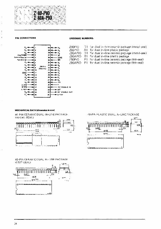
PIN CONNECTIONS ORDERING NUMBERS:
Z80PIOZ80PIOZ80APIOZ80APIOZ80PIOZ80APIO
O2070 6~
Control/Data Sli
POf! B/A Sol
~
~AsA4
GNDA:JA2A,
AoASf.8B STB
A ROY
DO0,
0 3DCOs
MfiC:i1fO1m
~B6B5B4B3B2B,BO+SV
-l-INT ENABLE IN
WI'INT ENABLE OUT
B ROY
01 for dual in-line ceramic package (metal-seal).81 for dual in-line plastic package01 for dual in-line ceramic pac;kage (metal-seal)B1 for dual' in-line plastic packageF1 for dual in-line ceramic package (frit-seal)F1 for dual in-line ceramic package (frit-seal)
MECHANICAL DATA (dimon.ion in mm)
40-PIN CERAMIC DUAL IN-LINE PACKAGE(METAL-SEAL)
40-PIN CERAMIC DUAL IN-LINE PACKAGE(FRIT-SEAL)
24
40-PIN PLASTIC DUAL IN-LINE PACKAGE
~~48,26 ~J
t::::~: ~:~:::::::::: i

MOSINTEGRATEDCIRCUITS
The SGS·ATES Z80 product line is a complete set of micro·computer components, development systems and supportsoftware. The Z80 microcomputer component set includesall of the circuits necessary to build high·performancemicrocomputer systems with virtually no other logic anda minimum number of low cost standard memory elements.
The l80·Counter Timer Circuit (CTC) is a programmable,four channel device that provides counting and timingfunctions for the Z80·CPU. The l80·CPU configures thel80·CTC's fOUl independent channels to operate undervarious modes and conditions as required.
Structure
• N·Channel Silicon Gate Depletion Load Technology• 28 Pin DIP• Single 5 volt supply• Single phase 5 volt clock• Four independent programmable 8·bit counter/16·bit
timer channels
Features
• Each channel may be selected to operate in either acounter mode or timer mode.
• Programmable interrupts on counter or timer states.
Fig. 5 - CTC BLOCK DIAGRAM
+5V GNU 'I'
I 11DATA
CONTROL
Product Specification
• A time constant register automatically reloads thedown counter at zero and the cycle is repeated.
• Readable down counter indicates number of counts·to·gountil zero.
• Selectable 16 or 256 clock prescaler for each timerchannel.
• Selectable positive or negative trigger may initiate timeroperation.
• Three channels have zero count/timeout outputs capableof driving Darlington transistors.
• Daisy chain priority interrupt logic included to providefor automatic interrupt vectoring without external logic.
• All inputs and outputs fully TTL compatible.
CTC Architecture
A block diagram of the l80·CTC is shown in figure 5.The internal structure of the Z80·CTC consists ofa l80-CPUbus interface, internal control logic, four'counter channels,and interrupt control logic. Each channel has an interruptvector for automatic interrupt vectoring, and interruptpriority is determined by channel number with channel 0having the highest priority.
The channel logic is composed of 2 registers, 2 countersand control logic as shown in figure 6. The registers includean 8-bit time constant register and an 8-bit channel controlregister. The counters include an 8-bit readable downcounter and an 8-bit prescaler. The prescaler may beprogrammed to divide the system clock by either 16 or 256.
ZERO COUNT/TIMEOUT II
CLOC K/TRIGGER II
ZERO COUNT/TIMEOUT I
CLOCK/TRIGGER I
ZERO COUNT/TIMEOUT 2
CLOCK/TRIGGER 2
CLOCK/TRIGGER J
25

Channel Counter and Register Description
Time Constant Register 8 bits, loaded by the CPU toinitialize and re-Ioad Down Counter at a count of zero.
Channel Control Register - 8 bits, loaded by the CPU toselect the mode and conditions of channel operation.
Down Cobnter - 8 bits, loaded by the Time ConstantRegister unaer program control and automatically at a
count of zero. At any time, the CPU can read the numberof counts-to-go until a zero count. This counter is decremented by the prescaler in timer mode and CLK/TRIGin counter mode.
Prescaler -f. 8 bit counter, divides system clock by 16 or256 for decrementing Down Counter. It is used in timermode only.
Fig. 6 - CHANrliEL slOCK DIAGRAM
CHANNELCONTROLREGISTER
AND LOGIC(8 BITS)
TIMECONSTANTREGISTER
(II BITS)
'I' PRESCALER(8 BITS)
ZERO COUNT/TIMEOUT
EXTERNAL CLOCK 'TIMER TRIGGER
Z80-CTC ~!.!1 Description,
CLK/TRG,3 Channel,3 External Clock or Timer Trigger(Input)
CLK/TRG\il Channel f/J External Clock or Timer Trigger(Input)
CLK/TRG2 Channel 2 External Clock or Timer Trigger(Input)
Channel \il Zero Count or Timeout(output, active high)
ZC/TO\il
CLK/TRG I Channel I External Clock or Tinier Trigger(Input)
CHANNELSIGNALS
,~
-5V
~LK/TRG2ZCIT02
ClK/TRGJ
CLKITRGI]-_......... lelTO,
°G01
02CPU 03
DATABUS 04
05
06
07
26

ZBO-CTC Pin Descriptio~ (continued)
ZC/TOI
ZC/TO::
IORO
Channel I Zero Count or Timeout(output, active high)
Channel:: Zero Count or Timeout(output, active high)
Channel Select (input, active high). Theseform a 2-bit binary address of the channelto be accessed.
Z80·CPU Data Bus (bidirectional, tristate)
Chip Enable (input, ~ctive low)
System Clock (input)
Machine Cycle One Signal from Z80-CPU(input, active low)
Input/Output Request from Z80·CPU (input,active low)
RD Read Cycle Status from the Z80-CPU (input,active low)
lEI Interrupt Enable In (input, active high)
lEO Interrupt Enable Out (output, active high).lEI and lEO form a daisy chain connectionfor priority interrupt control
INT Interrupt Request (output, open drain,active low)
RESET RESET stops all channels from counting andresets channel interrupt enabl~ bits in allcontrol registers. During reset'Wne ZC/TOf/j_2and INT go to the inactive states, lEO reflectsthe state of lEI, and the data bus output driversgo to the high impedance state (input, activelow)
CSO_ 1 CE~ CHANNEL ADDRESS
Timing Waveforms
CTC WRITE CYCLEIllustrated here is the timing for loading a channel control
word, time constant and interrupt vector. No wait states areallowed for writing to the CTC other than the automaticallyinserted (Tw*). Since the CTC does not receive a specificwrite signal, it internally generates its own from the lack ofan RD signal.
ferRO
T, T, T,
CTC READ CYCLEIllustrated here is the timing for reading a channel's
Down Counter when in Counter Mode. The value readonto the data bus reflects the number of external clock'srising edges prior to the rising edge of cycle (T2)' No waitstates are allowed for reading the CTC other than the automatically inserted (Tw*).
INTERRUPT ACKNOWLEDGE CYCLE
\'-----~;-
~- --
Some time after an interrupt is requested by the CTC, theCPU will send out an interrupt acknowledge (Mi and IORO).During this time the interrupt logic of the CTC will determine M1
the highest priority channel which is requesting an interrupt.To insure that the daisy chain enable lines stabilize, channelsare inhibited from changing their interrupt request statuswhen Mi is active. If the CTC Interrupt Enable Input (lEI)is active, then the highest priority interrupting channelplaces the contents of its interrupt vector register onto theData Bus when IORO goes active. Additional wait cyclesare allowed.
'27

Timing Waveforms (continued)
RETURN FROM INTERRUPT CYCLEIf a l80 peripheral device has no interrupt pending and is
not under service, then its lEO = lEI. If it has an interruptunder service (Le. it has already interrupted and received aninterrupt acknowledge) then its lEO is always low, inhibiting lower priority chips from interrupting. If it has an interrupt pending which has not yet been acknowledged, lEOwill be low unless an "ED" is decoded as the first byte of atwo byte opcode. In this case, lEO will go high until the nextopcode byte is decoded, whereupon it will again go low. Ifthe second byte of the opcode was a "40" then the opcodewas an RETI instruction.
After an "ED" opcode is decoded, only the peripheraldevice which has interrupted and is currently under servicewill have its lEI high and its lEO low. This device is the high·est priority device in the daisy chain which has received aninterrupt acknowledge. All other peripherals have lEI = lEO.If the next opcode byte decoded is "4D", this peripheraldevice will reset its "interrupt under service" condition.
Wait cycles are allowed in the MI cycles.
lEI
lEO
,------_--/___________--J/
T1
DAISY CHAIN INTERRUPT SERVICING
Illustrated at right is a typical nested interrupt sequencewhich may occur in the CTC In this sequence channel 2interrupts and is granted service. While this channel is beingserviced, higher priority channel I interrupts and is grantedservice. The service routine for the higher priority channelis completed and a RET! instruction is executed to indicateto the channel that its routine is complete. At this time theservice routine of lower priority channel 2 is completed.
CTC COUNTING AND TIMINGIn the counter mode the rising or falling edge of the CLK
input causes the counter to be decremented. The edge isdetected totally asynchronously and must have a minimumCLK pulse width. However, the counter is synchronous with<P therefore a setup time must be met when it is desired tohave the counter decremented by the next rising edge of <P.
In the timer mode the prescaler may be enabled by a risingor falling edge on the TRG input. As in the counter mode,the edge is detected totally asynchronously and must havea minimum TRG pulse width. However, when timing is tostart with respect to the next rising edge of <P a setup timemust be met. The prescaler counts rising edges of <P.
28
5 SECOND "RETro INSTRUCTION ISSUED ON COMPLETION OF CHANNEl2SERVlCE ROUTINE
INTERNALTIMER .J

eTC Programming
SELECTING AN OPERATING MODE
When selecting a channel's operating mode, bit f/J is set toI to Indicate this word is to be stored in the channel controlregister.
llSl!}I:".lli\11 H ~l()IlJ (J'\ I 1
HI III IlO
Bit 2 = f/J
Bit 2 = I
No time constant will follow the channelcontrol word. One time constant must bewritten to the channel to initiate operation.
The time constant for the Down Counterwill be the next word written to the selectedchannel. If a time constant is loaded while a
channel is counting, the present count willbe completed before the new time constantis loaded into the Down Counter.
Bit 7 f/J
Bit 7 = I
Channel interrupts disabled.
Channel interrupts enabled to occur everytime Down Counter reaches a count of zero.Setting Bit 7 does not let a preceding countof zero cause an interrupt.
Bit I = f/J
Bit I = I
Chann~continuescounting.
Stop operation. If Bit 2 = 1 channel willresume operation after loading a timeconstant, otherwise a new control wordmust be loaded.
Bit 6 = f/J
Bit 6 = I
Bit 5 =f/J
Bit 5 = I
Bit 4 = f/J
Bit 4 = I
Bit 3 =f/J
Bit 3 = I
Timer Mode Down counter is clocked bythe prescaler. The period of the counter is:
tc • P • TC
tc =system clock periodP = prescale of 16 or 256TC = 8 bit binary programmable timeconstant (256 max)
Counter Mode - Down Counter is clockedby external clock. The prescaler is not used.
Timer Mode Only-System clock <P is divided
by 16 in prescaler.
Timer Mode Only-System clock <P is dividedby 256 in prescaler.
Timer Mode negative edge trigger startstimer opera tion.Counter Mode - negative edge decrementsthe down counter.
Timer Mode - positive edge trigger startstimer operation.Counter Mode - positive edge decrementsthe down counter.
Timer Mode Only - Timer begins operationon the rising edge of 1'2 of the machinecycle following the one that loads the timeconstant.
Timer Mode Only - External trigger is validfor starting timer operation after rising edgeof T2 of the machine cycle following theone that loads the time constant. The Prescaler is decremented 2 clock cycles later ifthe setup time is met, otherwise 3 clockcycles.
LOADING A TIME CONSTANT
An 8-bit time constant is loaded into the Time Constantregister following a channel control word with bit 2 set. Allzeros indicate a time constant of 256.
LOADING AN INTERRUPT VECTOR
The Z80-CPU requires that an 8·bit interrupt vector besupplied by the interrupting channel The CPU forms theaddress for the interrupt service routine of the channelusing this vector. During an interrupt acknowledge cyclethe vector is placed on the Z80 Data Bus by the highestpriority channel requesting service at that time. The desiredinterrupt vector is loaded into the CTC by writing intochannel f/J with a zero in D0 D7-D3 contain the stored interrupt vector, D2 and DI are not used in loading the vector.When the erc responds to an interrupt acknowledge, thesetwo bits contain the binary code of the highest prioritychannel which requested the interrupt and D0 contains a
zero since the address of the interrupt service routine starts
at an even byte. Channel 0 is the highest priority channel.
29

ZBO-CTC A.C. Characteristics
TA =0° C to 70° C. Vee =+5 V ± 5%. unless otherwise noted
Number Symbol Parameter Min Max Unit Comments-
1 TcC Clock Cycle Time'- 250 111 ns2 TwCh Clock Width IHlgh) 105 2000 ns3 TwCl Clock Width (low) 105 2000 ns4 TfC Clock Fall Time 30 ns5- TrC- ,Clock Rise Time 30-r-- ns6 Th All Hold Times 0 ns
* 7 TsCSIC) CS to Clock T Setup Time 160 ns* 8 TsCEIC) IT to Clock i Setup Time 150 ns
9 TsIO(C) IORO 1 to Clock T Setup Time 115 ns10- TsRDIC)- R5 to Clock T Setup Time 115 ns
* 11 TdC(DO) Clock 1 to Data Out Delay 200 ns [2)12 TdCIDOz) Clock T to Data Out Float Delay 110 ns13 TsDIIC) Data In to Clock T Setup Time 50 ns14 TsMlIC) M 1 to Clock TSetup Time IINTA or M 1 Cycle) 90 ns15- TdM 111EO) Ml! to lEO 1 Delay linterrupt - 190---ns 131
Immediately preceding M 1 1 ) See Note A16 TdIOIDOT) IORQ 1 to Data Out Delay (I NTA Cycle) 160 ns [2117 TdIEI(lEOf) lEI 1 to lEO 1 Delay 130 ns 13118 TdIEI(IEOr) lEI T to lEO T Delay (after ED Decode) 160 ns 13)
*19 TdC(INT) Clock r to INT 1 Delay TcC+ 160 ns Timer Mode*20- TdCTRIINT) ClK/TRG r to INT L
TsCTR(C) Satisfied TcC+ 160 ns Counter ModeTsCTR(C) not Satisfied 2TcC+370 ns
21 TcCTR ClK Cycle Time 2TcC ns Counter Mode22 TrCTR ClK/TRG Rise Time 50 ns23 TfCTR ClK/TRG Fall Time 50 ns24 TwCTRl ClK/TRG Width (low) 200 ns25- TwCTRh - ClK/TRG Width (High) 200 ns26 TsCTRICc) ClK T to Clock T Setup Time for Immediate Count 210 ns Counter Mode27 TsCT,RICtl . TRG T to Clock i Setup Time for 210 ns Timer Mode
enabling of Prescaler on follOWing Clock T28 TdCIZCTOr) Clock T to ZC/TO T Delay 190 ns29 TdCIZCTOf) Clock 1 toZC/TO 1 Delay 190 ns
Notes A 2.5 TcC > (N-2) TdIEI(IEOF)+ TdM 1(IEO)+TsIEI(IO)8 RESET must be active for a minimum of 3 clock cycles11) TcC = TwCh + TwCI + TcC + TrC12) Increase delay by 10 nsec for each 50 pF increase In loading. 200 pF maximum for data lines and 100 pF for control lilies131 Increase delay by 10 nsec for each 10 pF Increase in loading. 100 pF maximum
OUTPUT LOAD CIRCUIT
CAl - CA4 lN914 OR EQUIVALENTCR
2Cl 50 pF ON ALL PINS
30

Z80A-CTC A.C. Characteristics
TA 0" C to 70" C. Vee +5 V :t S'l, lInless otherwise noted
Number Symbol Parameter Min Max Unit Comments
1 TdC Clock Cycle Tlfne 400 [1] ns2 TwCh Clock Width (High) 170 2000 ns3 TwCl Clock Width (lOl,y1 170 2000 ns4 TIC Clock Fall Time 30 ns5- TrC- Clock Rise Time 30-r- ns6 Th All Hold Times 0 ns
* 7 TsCS(CI CS to Clock T Setup Time 250 ns* 8 TsCE(C) EE to Clock i Setup Time 200 ns
9 TsIO(CI 10RO ! to Clock T Setup Time 250 ns10-- TsRDICI- Ri5 to Clock i Setup Time 240 ns
*11 TdCIDO) Clock ! to Data Out Delay 240 ns [2112 TdC(DOz) Clock i to Data Out Float Delay 230 ns13 TsDIIC7 Data In to Clock i Se!up Time 60 ns14 TsMllCI M1 to Clock i Setup Time (INTA or M 1 Cycle) 210 ns15- TdMlIIEO) M11 to lEO! Delay I,nterrupt 300-r- ns [3]
Immediately preceding M 1 ) See Note A16 TdIOIDOT) 10RO 1 to Data Out Delay IINTA Cycle) 340 ns [2117 TdIEIIIEOt) lEI 1 to lEO 1 Delay 190 ns 13]18 TdIEI(JEOrl lEI i to lEO i Delay (after ED Decodel 220 ns 131
*19 ITf Clock j to INT 1 Delay TcC+230 ns Timer Mode*20 IOL I I\III\J II' i to INT 1
Satisfied TcC+230 ns Counter ModeTsCTR(C) not Satisfied 2TcC+530 ns
21 TcCTR ClK Cycle Time 2TcC ns Counter Mode22 TrCTR ClK/TRG Rise Time 50 ns23 TfCTR ClK/TRG Fall Time 50 ns24 TwCTRl ClK/TRG Width (lowl 200 ns25- TwCTRh- ClK/TRG Width (Hlghl 200 ns26 TsCTRICcl ClK j to Clock 'j Setup Time for Immediate Count 300 ns Counter Mode27 TsCTRICt) TRG j to Clock i Setup Time for 210 ns Timer Mode
enabling of Prescaler on following Clock i28 TdC(ZCTOrl Clock i to ZC /TO i Delay 260 ns29 TdC(ZCTOt) Clock! to ZC /TO ! Delay 190 ns
Notes A 2,5 TcC > (N-2) TdIEI(JEOF)+TdM 1(IEOI+ TslEl(lOIB RESET must be active for a minimum of 3 clock cycles111 TcC = TwCh + Twel + TcC + TrC[21 Increase delay by 10 nsec for each 50 pF Increase In loading, 200 pF maximum for data lines and 100 pF for control lines[3] Increase delay by 10 nsec for each 10 pF Increase In loading,. 100 pF maximum
OUTPUT LOAD CIRCUIT
CR , - CR4 lN914 OR EQUIVALENTCR
2CL " 50 pF QN ALL PINS
31

Timing measurements are made at the following voltages,unless otherwise specified:
CLOCK
CS 0-1
DATA
DATA
DATA
lEI
lEO
ClK IITRG o.]
.32
A.C. Timing Diagram
"'" "0"
CLOCK Vcc-O.6V O.45VOUTPUT 2V O.8V
INPUT 2V O.8V
FLOAT t!.V ±O.5V

Absolute Maximum RatingsTemperature Under BiasStorage TemperatureVoltage On Any Pin with Respect to GroundPower Dissipation
O°C to 70°C-65°C to +150°C
-O.3V to +7VO.8W
* CommentStresses above those listed under" Absolute Maximum Rating" may cause permanent damage to the device. This is a stress rating only andfunctional operation of the device at these or any other condition above those indicated in the operational sections of this specification isnot implied. Lxposure to absolute maximum rating conditions for extended periods may affect device reliability.
Z80-eTC D.C. CharacteristicsTA= DoC to 70°C, Vcc= 5V ± 5% unless otherwise specified
Symbol Parameter Min Max Unit Test Condition
VILe I Clock Input Low Voltage -0.3 0045 V
VIHC Clock Input High Voltage [1] Vcc-06 VCC+03 V
VIL Input Low Voltage -0.3 0.8 V
VIH Input High Voltage 2 Vec V
VOL Output Low Voltage 004 V 'OL 2 rnA
VOH Output High Voltage 204 V 'OH = -250 IJ.A
'CC Power Supply Current 120 rnA Te = 400 nsec
III Input Leakage Current 10 IJ.A VIN=OtoVCC
'LOH Tri-State Output Leakage Current in Float 10 J..LA VOUT = 2A to VCC
'LOL Tri-State Output Leakage Current in Float -10 J..LA VOUT OAV
IOHD Darlington Drive Current -1.5 rnA VOH = 1.5V
REXT 390n
Z80A-CTC D.C. CharacteristicsTA= DoC to 70°C, Vcc= 5V ± 5% unless otherwise specified
Symbol Parameter Min Max Unit Test Condition
V,LC Clock Input Low Voltage -0.3 OA5 V
VIHC Clock Input High Voltage [1] VCC-06 VCC+0 .. 3 V
VIL Input Low Voltage -0.3 08 V
VIH Input High Voltage 2 VCC V
VOL Output Low Voltage 0.4 V 'OL = 2 rnA
VOH Output High Voltage 2.4 V IOH -250 IJ.A
'CC Power Supply Current 120 rnA TC 250 nsec
III Input Leakage Current 10 J..LA VIN = 0 to Vec
'LOH Tri-State Output Leakage Current in Float 10 J..LA VOUT 2A to Vce
'LOL Tri-State Output Leakage Current in Float -10 J..LA VOUT OAV
'OHD Darlington Drive Current -1 5 rnA VOH 1.5V
REXT 390£2
33

CapacitanceTA=2SoC,f= I MHz
Symbol
C",
COUT
Parameter
Clock Capacitance
Input Capacitance
Output Capacitance
Max. Unit Test Condition
20 pF Unmeasured Pins
5 pF Returned to Ground
10 pF
PIN CONNECTIONSORDERING NUMBERS:
GNO
lIllZCITOe
lCITO,
ZCITOz
IORQINT ENABl.E OUT
iNTINT ENAIL.E IN
Iii
MECHANICAL DATA (dimensions in I]1ml
03Dz0,Of+l5V
ClKITRot
ClKITRG,
ClKITRGZ
ClKITRG3
- cs,cseREID~..
Z80CTCZ80CTCZ80ACTCZ80ACTCZ80CTCZ80ACTC
D 1 for dual in-line ceramic package (metal-seal)B1 for dual in-line plastic packageD1 for dual in-line ceramic package (metal-seal)B 1 for dual in-line plastic packageF1 for dual in-line ceramic package (frit-seal)F1 for dual in-line ceramic package (frit-seal)
28-PIN CERAMIC DUAL IN-LINE SLAM PACKAGE
28-PIN CERAMIC DUAL IN-LINE PACKAGE(FRIT-SEAU
28-PIN PLASTIC DUAL IN-LINE PACKAGE
~~~J),Q2
373m..
34

MUSINTEGRATEDCIRCUITS
The Z-80 DMA (Direct Memory Access) circuit is a programmable single-channel device which provides all address,timing and control signals to effect the transfer of blocks ofdata between two ports within most micmprocessor-basedsystems. These ports may be either system main memory orany system peripheral i/o device. The DMA can also searcha block of data for a particular byte (bit maskable), with orwithout a simultaneous transfer.
Structure• N·channel Silicon Gate Depletion Load Technology• 40 Pin DIP• Single 5 volt supply• Single phase 5 volt clock• Sing,1e channel, two port
Features• Three classes of operation:
- Transfer Only-Search Only-Search-Transfer
• Address and Block Length Registers fully buffered.Values for next operation may be loaded without disturbing current values.
• Dual addresses generated during a transfer (one for readport and one for write port).
• Programmable data transfers and searches, automatically incrementing or decrementing the port addressesfrom programmed starting addresses (they can also remainfixed).
Fig. 7 - DMA INTERNAL BLOCK DIAGRAM
Product Specification
• Three modes of operation:-Byte-at-a-time' One byte transferred per request-Burst' Continues as long as ports are ready--Continuous: Locks out CPU until operation complete
• Timing may be programmed to match the speed of anyport
• Interrupts on Match Found, End of Block, or Ready,may be programmed.
• An entire previous operation may be repeated automatically or on command. (Auto restart or Load)
• The DMA can signal when a specified number of byteshas been transferred, without halting transfer
• Multiple DMA's easily configured for rotating priority.• The channel may be enabled. disabled or reset under
software control• Complete channel status upon program (CPU) request.• Up to 1.25 megabyte/second Search.• Daisy-chain priority interrupt and bus acknowledge in
cluded to provide automatic interrupt vector(ng and busrequest control, without need for additional externallogic
• TTL compatible inputs and outputs• The CPU can read current Port counters, Byte counter,
or Status Register. A mask byte can be set which defineswhich registers can be accessed during read operations.
+5V GND
A15 AO D7 DO
iN"! lEI lEO BAI BAO RDY
CONTROLAND
STATUSREGISTERS
BUS CONTROLLOGIC
35

DMA ArchitectureA block diagram of the Z80 DMA is shown in Figure 7.
The internal structure consists of the following circuitry:
• Bus Interface: provides driver and receiver circuitry 10
interface to the Z80-CPU Bus
• Control I-ogicand Registers. set the class, mode and otherbasic control parameters of the DM A
• Address. Byte Count and Pulse Circuitry: generates theproper port addresses for the read and write operations,with provisions for incrementing or decrementing theaddress. When zero bytes remain to be handled, the bytecount circuitry sets a nag in the status register Pulsecircuitry generates a pulse each time the byte counterlower 8-bits equal the pulse register.
• Timing Circuitry: allows the user to completely specifythe read/write timing for each port
• Match Circuitry. holds the match byte and a maskbyte which allows for the comparison of only certainbits within the byte. If a match is encountered during aSearch or Transfer, this circuitry sets a nag in the statusregister.
• [NT and BUSRQ Circuitry.' includes a control register which specifies the conditions under which the DMAcan generate an interrupt; priority encodi~to selectbetween the generation of an INT or BUSRQ outputunder these conditions; and an interrupt vector registerfor automatic vectoring to the interrupt service routine
• Status Register: holds current status of DMA.
Register Description
The following DMA-internal registers are available to theprogrammer:
Control Registers: Write only; 8 bits. Hold DMA controlinformation: such as, when to initiate an interrupt or pulse,what mode or class of operation to perform, etc.
Timing Registers: Write only; 8 bits. Hold read/write timingparameters for the two ports.
Interrupt Vector Register: Read/write; 8 bits. Holds the8-bit vector that the DMA will put onto the data bus afterreceiving an IORQ during an interrupt acknowledge sequence if it is the highest priority device requesting aninterrupt (This register is readable only during interruptacknowledge cycles.)
Block Length Register: Write only; 16 bits. Contains totalblock length of data to be searched and/or transferred.
Byte Counter: Read only; 16 bits. Counts number of bytestransferred (or searched). On a Load or Continue the ByteCounter is reset to zero. Thereafter, each byte transfer operation increments it until it matches the contents of theBlock Length Register, at which time End of Block is set inthe status register and operation is suspended if programmed. Also if so programmed the DMA will generate aninterrupt.
36
Match Register: Write only; 8 bits. Holds the byte forwhich a match is being sought in Search operations.
Mask Register: Write only; 8 bits. Holds the 8-bit mask todetermine which bits in the match register are to be examined for a match.
Starting Address Registers (Port A and Port B): Write only;16 bits each. Hold the starting addresses (upper and lower8 bits) for the two ports involved in Transfer operations. InSearch Only operations, only one port address would haveto be specified. Only memory starting addresses requireboth upper and lower 8 bits; I/O ports are generally addressed with only the lower 8 bits, and in this case the address contained in the register is a generally ftxed address.
Address Counters (Port A and Port B): Read only; 16 bitseach. These counters are loaded with the contents of thecorresponding Starting Address Registers whenever Searches or Transfers are initiated with a Load or Continue. Theyare incremented, decremented or remain ftxed, as programmed.
Pulse Control Register: Write only; 8 bits. The content oftrus register is continuously compared with the lower eightbits of the byte counter. When they become equal, the INToutput is activated. Since this occurs while BUSRQ andBUSAK are both active, the CPU does not interpret trus asan in terrupt request. Instead, the signal is used to communicate with a peripheral I/O device. When the Pulse ControlRegister contains a value n, the first pulse is generated aftern + I bytes of search or transfer. The next and all subsequent pulses occur at 256-byte intervals.
Status Register: Read only; 8 bits. Match, End of Block,Ready Active, Interrupt Pending, and DMA Cycle Occurredbits indicate these functions when set.
Modes of Operation
The DMA may be programmed for one of three modes ofoperation. (See Command Register 2B.)
• Byte at a time. control is returned to the CPU after eachone-byte cycle
• Burst: operation continues as long as the DMA's RDYinput is active, indicating that the relevant port is readyControl returns to the CPU when RDY is inactive or atend of block or a match if so programmed
• Continuous: the entire Search and/or Transfer ofa blockof data is completed before cont rol is returned to CPU

Classes of OperationThe DMA has three classes of operation: Transfer only,
Search Only and a combined Search-Transfer. (See Command Register lA.)
During a Transfer, data is first read from one port andthen written to the other port, byte by byte. (The DMA'stwo ports are termed Port A and Port B.) The ports may beprogrammed to be either system main memory or peripheral I/O devices. Thus, a block of data might be written froma peripheral to another; or it might be written from onearea in main memory to another; or from a peripheral tomain memory.
During a Search, data is read only, and compared byte bybyte against two DMA-internal registers, one of which contains a match byte and the other an optional mask bytewhich allows only certain bits to be compared. It any byteof searched data matches, a DMA-internal status bit is set:ifprogrammed to do so, the DMA will then suspend operationand/or generate an interrupt.
The third class of operation is a combined SearchT'ransfer. In such an operation a block of data is transferredas described above until a match is found; then, as in aSearch Only operation, the transfer may be suspended and/or an interrupt generated
AddressingThe DMA's addressing of ports is either fixed or sequen
tial, incrementing or decrementing from a starting address.The length of the operation (number of bytes) is specified bythe programmed contents of a block length register. TheDMA can address block lengths of up to 64K bytes. During atransfer two separate port addresses are generated, one during the Read cycle and one during the Write cycle.
Operating Sequence
Once the DMA has been programmed it may be "Enabled" (Command Register 2A or 2D). In the enabled condition when Ready goes active the DMA will request ~he
bus by bringing BUSRQ low. The CPU will acknowledgethis with a BUSACK which will normally be attached toBAl. When the DMA receives BAI it Will start its programmed operation releasing BUSRQ to a "high" state when itis through.
Z-80 DMA Pin Description
+5V
GND
<P
Do An0, A,
0, A,
~~ST~EM 0, A)
BUS O.
A,
0, A,
0, A, SYSTEM
A, :3~AESS
BUS rs~ A,
CONTROL ~ A"~ BAD
AU
An
A"
A"
~~/:AIT} ~~~TAOl
}'NTERRUPTCONTROL
System Address Bus All sixteen of these pins areused by the DMA to address system main memory or an I/O port (output)
System Data Bus. Commands from the CPU,DMA status and data from memory or peripherals are transferred on these tristate pins (input/output)Power
Ground
System clock (input)
INT
lEI
lEO
RDY
Machine cycle One signal from CPU (input)
Input/Output Request to and from the SystemBus (input/output)
Memory REQuest to the System Bus (input/output)
ReaD to and from the System Bus (input/output)
WRite to and from the System Bus (input/output)
Chip Enable: may also be programmed to beWAIT during time when BAI is low (input)
BUS ReQuest.. Requests control of the CPUAddress Bus, Data Bus and Status/Control Bus(input/output, open drain)
Bus Acknowledge In Signals that the systembuses have been released for DMA control(input)
Bus Acknowledge Out.. BAI and BAO form adaisy-chain connection for system-wide prioritybus control (output)
INTerrupt request (output, open drain)
Interrupt Enable In (input)
Interrupt Enable Out lEI and lEO form a daisychain connection for system-wide priority interrupt control (output)
ReaDY is monitored by the DMA to determinewhen a peripheral device associated with a DMAport is ready tor a read or write operation(input.. programmable as active high or low)
37

DMA Command Write Cycle
Illustrated here is the timing associated with a commandbyte or control byte being written to the DMA which is tobe loaded into internal registers, Z80 Output instructionssatisfy this timing,
DMA Timing Waveforms
<I>
D A T A --!--+__--I
DMA Register Read Cycle
This timing is used when a read operation is performed onthe DMA to access the contents of the Status Register,Address Counter or other readable registers Z80 Input instructions satisfy this timing, DATA
STD Memory Timing
This timing is exactly the same as used by the l80-CPU toaccess system main memory, either in a Read or Writeoperation. The DMA will default to this timing after apower-on reset, or when a Reset or Reset Timing commandis written to it; and unless otherwise programmed, will usethis timing during all Transfer or Search operations involvingsystem main memory. During the memory Read portion ofa transfer cycle, data is latched in the DMA on the negativeedge of <P during T3 and held into the following Write cycleDuring the memory Write portion of a transfer cycle, datais held from the previous Read cycle and released at the endof the present cycle.
NOTE: The DMA is normally programmed for a 3 T-cycleduration in memory transactions, But WAIT issampled during the negative transition of T2, andif it is low, T2 will be extended another T-cycle,during which WAlT will again be sampled_ Theduration of a memory transaction cycle may thusbe indefinitely extended_
I T, I T, I T3 I,.---fLJLJLJL
-LATCHED BY DMA ON BUS DURING A TRANSFER
WAIT I \~ ,. __ .__ -' L _
HELD FROM PREVIOUS READ
STD Peripheral Timing
This timing is identical to the l80-CPU's Read/Write timingto I/O peripheral devices The DMA will default to thistiming after a power-on reset, or when a Reset or ResetTiming command is written to it; and unless otherwise programmed, will use this timing during all Transfer or Searchoperations involving I/O peripherals. During the I/O Readof a transfer cycle, data is latched on the negative edge of <Pduring T3 and is then held into the Write cycle, During anI/O Write, data is held from the previous Read cycle untilthe end of the Write cycle
NOTE. If WAIT is low during the negative transition ofTw*, then Tw* will be extended another T-cycleand WAIT will again be sampled. The duration of aperipheral transaction cycle may thus be indefinitelyextended
38
IORQ
T, T, T,
H:~fA~Nci~lNEXT READ
fRU:~~~E~

DMA Timing Waveforms (continued)
ISHOWN PROGRAMMED FOR 4 CYCLES I
1""'00----- VARIABLE LENGTH--_
1, I 1, I 1, I 1,
Variable Cycle
Ao - A15
iOROr-I
r-M~EQ
I
r-AD I
The Variable feature of the DMA allows the user to programthe DMA's memory or peripheral transaction timing to val uesdifferent than given above in the standard default diagrams.This permits the designer to tailor his timing to the particularrequirements of his system components, and maximizes thedata transfer rate while eliminating external signal conditioning logic. Cycle length can be two to four T-cycles (more ifWAIT is used). Signal timing can be varied as shown. Duringa transfer, data will be latched by the DMA on the clock edgecausing the rising edge of RD and will be held on the datalines until the end of the following Write cycle.
(See Timing Control Byte, page 9).WAiT IMEM) .1
r-I
\L. _
DMA Bus Request and Acceptance forByte-at-a-Time, Burst,and Continuous Mode
Ready is sampled on every rising edge of <P. When itis found to be active, the following rising edge of <Pgenerates BUSRQ. After receiving BUSRQ the CPU willgrant a BUSAK which will be connected to BAI eitherdirectly or through the Bus Acknowledge Daisy Chain.When a low is detected on BAI for two consecutiveedges of <P, the next rising edge of <P will start an activeDMA cycle.
DMA Bus Release at End of Blockfor Burst or Continuous Mode
Timing for End of Block and DMA n'ot programmedfor Auto-restart.
WAiT 1101 I \__ ________-J '- _
DMA INACTIVE~DMAACnVE
BUSRO l\----..---XI-~:~:~~;~I
DMA ACTlVE .....~DMA INACTIVE
DMA Bus Release with 'Ready'for Burst and Continuous Mode
The DMA will relinquish the bus after RDY has goneinactive (Burst mode) or after an End of Block or aMatch is found (Continuous mode). With RDY inactive,the DMA in Continuous mode is inactive but maintainscontrol of the bus (BUSRQ low) until the cycle is resumed when RDY goes active
-I-
RDY )--'0--'--+(-----' CONTINUOUS'y-BURSTMODE r-MODEt}~----- - - ---------7
DMA ACTlvE-.-I- ~N~~TlVE -~_DMAACTIVE
39

Reading from the DMA Internal Registers
DMA Bus Release for Byte-at-a-Time Mode
In the Byte mode the DMA will release BUSRQ onthe rising edge of <P prior to the end of each Read cycle in Search Only or each Write cycle in a Transfer, regardless of the state of RDY. The next bus request willcome after both BUSRQ and BAI have returned high.
DMA Bus Release with Match forBurst or Continuous Modes
When a Match is found and the DMA is programmedto stop on Compare, the DMA performs an operation onthe next byte and then releases bus.
RDY ..;..A;;;.C.;..T -----?),.. _
BUSRa ~\--
BAi ~/DMA ACTIVE I_DMA INACTIVE
BUSRa --,....----\;>--~<r-/1
- BYTE N--I.... BYTE N+l ....1MATCH FOUND IN
THIS BYTE DMA ACTIVE ..... _DMA INACTIVE
Reading the DMA Internal Registers
The CPU can read seven internal DMA registers, alwaysin the following order: Status, lower byte of the BlockLength register, upper byte of the Block Length register,lower byte of the Port A Address, upper byte of the Port AAddress, lower byte of the Port B Address and the upperbyte of the Port B Address.
The Read Mask register must be programmed to eitherinclude or exclude any of these seven registers by program-
ming a 1 (include) or 0 (exclude) in the appropriate positions of the Read Mask register. After a Reset or Load, theread sequence must be initiated through an Initiate ReadSequence command (Command Byte 2D). The sequence ofreading all registers that are not excluded by the Read Maskregister must be completed before a new Initiate Read Sequence or RD Status command.
Programming the DMA
Previous sections of this specification have indicated thevarious functions and modes of the DMA. The diagrams andcharts below show how the DMA is programmed to selectamong these functions and modes and to adapt itself to therequirements of the user system.
The Z80-DM A chip may be in an" enable" sta te, in wh ichit can gain control of the system buses and direct the transfer of data between its ports. or in a "disable" state, whenit cannot gain control of the bus Program commands canbe written to it in either state. but writing a command to itautomatically puts it in the disable state. which is maintaineduntil an enable command is issued to the DMA. The CPUmust program it in advance of any data search or transfer byaddressing it as an I/O port and sending it a sequence ofcomman<;l bytes via the system data bus using Output instructions. When the DMA is powered up or reset by any
40
means, the DMA is automatically placed into a disablestate, in which it can initiate neither bus requests nor datatransfers nor interrupts.
The command bytes contain information to be loadedinto the DMA's control and other registers and/or information to alter the state of the chip. such as an Enable Interruptcommand. The command structure is designed so that certain bits in some commands can be set to alert the DMA toexpect the next byte writ ten to it to be for a particularinternal register.
TIle following diagrams and charts give the function ofeach bit in the six different command bytes. Two of theseare defined as being from Group I. and are termed commandbytes 1A and I B These Group I commands contain themost basic DMA set-up information The other four arecategorized as Group 2. and are termed commands 2A. 2B.2C and .~D. Group 2 words specify more detailed set-upinformation

Programming the DMA (continued)
Command Register lA
0= N/A (Command lBI1 = Transfer0= Search
1 1 = Search/Transfer0= Port B - Port A1 = Port A - Port B
InTimeSequence
BLOCK LENGTH (UPPER BYTE)
A "1" in positions 03 through 06means that the indicated byte will follow. Note that the sequence of bytesis absolutely rigid.
lbe OMA always transfers or searches one byte more than the numberwritten into the Block Length registers.A "0" in the block length register results in the transfer or search of 216 +I bytes. The shortest programmableblock length is therefore two byteslong, programmed by writing a 1 intothe Block Length register.
Command Register IB
o= Port B-Memory1 = Port A-Memory0= Port B-I/O
1 1 = Port A-I/Oo= Port Address Decrements1 = Port Address Increments
1 = Port Address Fixed
Timing Byte
Command Register 2A
1 Stop On MatchL..-_+-_-+ 1 = Interrupt Enable
L..- -+__j- 1 = DMA Enable
MASK BYTE (1 =MASK =IGNORE; 0 =UNMASK =COMPARE)
MATCH BYTE
o 0 =Cycle Length =4o 1 =Cycle Length = 31 0 = Cycle Length = 2
0= iORQ Ends Y, Cycle Early0= MREO Ends Y, Cycle Early
0= Fm Ends Y, Cycle Early0= WR Ends Y, Cycle Early
For transfers, this byte is nonnally written twice, oncefor Port A and again for Port B.
41

Programming the DMA (continued)
Command Register 2B
Byte = 0Continuous:= 0
Burst 1Do not program = 1
1 If "Interrupt Before Requesting Bus"is selected (by a 1 in bit 6 of the Interrupt Control byte), the lo80 DMAdoes not request the bus until thefollowing set of instructions has beenreceiyed by the lo80 DMA:
• Enable after RETI command (B7in Command byte 2D)
• Enable DMA command (87 inCommand byte 2D)
r. A RET! instruction that resets theIUS (Interrupt Under Servicelatch) in the Z-80 DMA
Interrupt Control Byte I
Interrupt Vector
1 = Status Affects Vector1 Interrupt Before Request Bus
PORT B STARTING ADDRESS (LOW·ORDER HALF)
0= Interrupt On RDY1 = Match0= End Of Block1 = Match, End Of Block
Command Register 2C
0= Ready Act'lve Low1 Ready AClive High
0= Ct Only1 = cEMIITf Multiplexed
0= Stop On End or Block1 = Auto Repeal On End at Block
42

Programming the DMA (continued)
Command Register 2D
HEXC3
C7CBCF03ABAFA3
8783A7
BFB3
8B87
BB
0= Reset Interrupt circuitry, disable interrupt and bus request logic. unforceinternal ready condition, disable "MUXCE" and stop auto repeat
1 ~ Reset Port A Timing to standard 2-80 CPU timinga = Reset Port B Timing to standard 2 80 CPU timing1 Load starting address for both ports. clear byte counter·0= Addresses continue from present locations, clear byte countera = Enable interrupts1 Disable interruptsa = Reset and disable interrupt circuits (like RETI) and un force the internal
ready condition1 = Enable DMAJ Both affect all operations except interrupts, but do nota = Disable DMA reset any functions1 Initiate read sequence to the first register designated as readable by the
Read Mask register1 = Set read status so next read is from status registera = Force an internal ready condition independent of the ROY input. Used
for memory-to-memory operations where no ROY signal is neededThis command does not function in the "byte-at-·a··time" mode
a = Clear Match and End of Block status bits1 = Enable after RETI so OMA will request bus only after receiving a RETI
Must be followed by an Enable OMA commanda = Read mask is the following byte
Read Mask (1 = enablel
Status'----- Byte Counter (low byteI
'------- Byte Counter (high bytel'---------- Port A address (low byte)
'------------- Port A address (high byte)'-------------- Port B address (low byte)
'----------------- Port B address (high byte)
* Loading Port Addresses The "Load" command (CF in Command Register 20) loads a fixed address only into a port selectedas the source, not into a port selected as the destination. Therefore. the destina tion address must be loaded by temporarily mislabeling the destination as the source
The following example is a set-up procedure for a transfer fromPort A to Port B:
I Command byte IA with B as source port2 Command byte 20 with CF = load3 Command byte IA with A as source port40 Command byte 20 with CF = load50 Command byte 20 with 87 = Enable OMA
This manipulation is required only when the destination has afixed address
Status Register
Has Not OccurredHas Occurred
aa = Match
a 0 btl Of Block
43
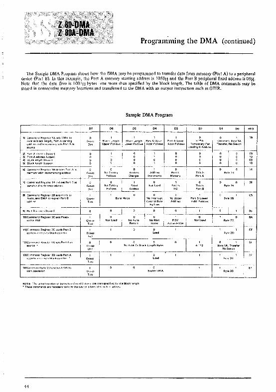
Programnling the DMA (continued)
The Sample DMA Program shows how the DMA may be programmed to transfer data from memory (port A) to a peripheraldevice (port B). In this example, the Port A memory starting address is lOS0H and the Port B peripheral fixed address is OSH.Note that the data flow is lOOIH bytes-one more than specified by the block length. The table of DMA commands may bestored in consecutive memory locations and transferred to the DMA with an output instruction such as OTIR.
Sample DMA Program
D7 D6 D5 D4 D3 D2 D1 DO HEX
1) Command Register lA sets OMA to a I 1 1 1 1 a a 1 79receive block length, Port A starting Group ! Block Length Block Length Port A Upper Port A Lower B ->A Command Byte 1Aaddress and temporarily sets Port Bas One Upper Follows LO\'Ver Follows Addr Follows Addr Follows Temporary For Tramfer, No Searchsource Loading B Address
21 Port A address Hower!
I50
3) Port A address lupped 104) Block length (lower) 005) Block length (upped 10
6) Command Register 1B defines Port A as a a a 1 a 1 14memory with incrementing address Group No Timing Address Address Port Is This Is Byle 1B
One FolloVw'S Changes Increments Memory Port A
7) Command Register 1B defines Port 8 as a a 1 a 1 a 2Bperipheral with fixed address Group No Timing Fixed Not Used Port Is This Is Byte 1B
One Follows Address I/O Port B
8) Command Register 28 sets mode to 1 a a 1 C5Burst, sets OMA to expect Port B Group Burst Mode No Interrupt No Upper Port BLower Byte 2Baddress Two Control Byte Address Addr Follows
Follows
9) Port B address lIo.......erl I aS
10)Command Register 2C sets Ready 1 a a a 1 a BAactive High Group Not Used No Auto No Wait RDY Not Used Byt.2C
Two Restart States Active HIGH
11)Command Register 20 loads Port B 1 a CFaddress and resets block counter Group Load Byte2D
Two
12)Command Register 1A sets Port A as a a a 1 a 1 03source· Group No Addr Or Block Length Bytes A ->B Byte lA, Transfer
One No Search
13)Command Register 20 loads Port A 1 a CFaddress and resets block counter, • Group Load Byte 20
Two
14)Command byte 2D enables DMA to 1 a B7start operation Group Enable OMA Byte 20
Two
NOTE: The actual number of bytes transferred is one more than specified by the block length• These commands are necessary only in the case of a fixed destination address
44

Absolute Maximum RatingsTemperature Under BiasStorage TemperatureVoltage On Any Pin with
Respect to GroundPower Dissipation
O°C to +70°C_65°C to +150°C-O.3V to +7V
*Comment
Stresses above those listed under" AbsoluteMaximum Rating" may cause permanentdamage to the device. This is a stress ratingonly and functional operation of the deviceat these or any other condition above thoseindicated in the operational sections of thisspecification is not implied. Exposure toabsolute maximum rating conditions forextended periods may affect device reliability.
D.C. Characteristics
TA =cOe to 70°C, Vee =sv ±5% unless otherwise specified
Symbol Parameter Min Max Unit Test Condition
VILe: Clock Input Low Voltage -03 045
VIHC Clock Input High Voltage VCC- 6 5.5
VIL Input Low Voltage -0.3 08 V
VIH Input High Voltage 20 55
VOL Output Low Voltage 04 10L = 3 2 rnA for BUSRQ10L = 2 0 rnA for all others
VOH Output High Voltage 2.4 10H = ·250~A
ICC Power Supply Current z.sODMA 150 rnA tc = 400 nsZ·80A DMA 200 rnA Ie =25005
III Input Leakage Current 10 ~A VIN = 0 to VCC
ILOH Tri"State Output Leakage Current in Float 10 ~A VOUT = 24 to Vce
i LOL Tri·Stalc Output Leakage Current in Float -10 ~A VOUT=04V
ILD Data Bus Leakage Current in Input Mode ±IO ~A 0<; VIN <; VCC
Capacitance
TA =25°C, f = I MHz
Symbol Parameter Max. Unit Test Condition
Cct> Clock Capacitance 35 pF Unmeasured Pins
C1N Input Capacitance 5 pF Returned to Ground
CaUl Output Capacitance 10 pF
Vee
FROM
V:fr~To-<~>--_--I<::I--"" CL = 50 pF. Increase delay by IO ns for each 50 pFincrease in CL, up to 200 pF maximum.
45

A.C. Timing Diagrams
ZSO and ZSOA as a Peripheral Device (Inactive State)
Timing measurements are made at the following voltages. unless otherwise specified: "1 ,. "0"
CLOCK 42V 08VOUTPUT 20V 08VINPUT 20V 08VFLOAT :'V +05V
'I'
toM(IOl-
lEI
lEO
INTCONDITION
NOTE: This diagram does not show an actual timing sequence. Refer to this diagram only for the detailed timing relationshipsof individual edges. Use the illustrations in the "DMA Timing Waveforms" section as an explanation of the varioustiming sequences.
46

A.C. Characteristics
Z80-DMA as a Peripheral Device (Inactive State)
TA = O°C to 70°C, Vcc = +5V+5%, Unless Otherwise Noted
210 160 nsec
190 130 om300 190 met
210
500
200 150 met
200 150 nsec
"l w('I'HI
tWltl'll
" ,
fJi1r" 15'I'lC51
IOAlal
tS'I'WI00 7
IF(01
'SUEtl
'" lS'/,(Ml)
(NT IOlln
BAO IOHmQIIOLleQI
Clm:kPI,"o{1
Control S'<jlldl Setup Tim\! 10 A'SI!Hj Edql'o! 'l'dur,nqW"11! Cycle jlORQ W-A CEl
.",:,"0 "",,'"
lEI Sewp T'lfnc to FallIn!] Ed~W of IORO Ilutlll<j JNTA Cycle
,tU U""'V"''' HUll
J,," PliO< 'u MIlS,,, NOll, A
Ml St:lllfJ T,me to R,SilHj E{J~Je of 'I' durllllj fNT A or MlCyete See Note B
AD S'~ll1P T,tTle to RISIII[J Et1~jI! of ,I· dllr,nq M1 Cyel.'
BAD oel"y from R,Sing Edge of BAIBAO Del.ly horn Failing Ed\jc of BAI
Z.. 800MA
400
170170
111
30
Z.·80A DMAo
105105
11120002000
30
380
UNIT
mecmet
* Z-80A DMA Timing Specifications are preliminary
Z80-DMA as a Bus Controller (Active State)T A = DoC to 70°C, Vcc = +5V±5%, Unless Otherwise Noted
PARAMETER
BUSAO 10(80)
IFIC) Delay to Float (MR'EO lORa AD and WRl
400180180
tc - 40
2502000 1102000 110
30
100130100110
8090
100100
nsec2000 nsec2000 nsec
30 nsec
11090
mecmec
15090
mecmec
8585 mec85 mec85 nsec
75 nsec85 mec85 mec85 nsec
859585 nsec85 r1SCC
65808080
NOTES: II Data must be enabled onto the DMA data bus when Rl5 is active. II Z-80A DMA timing specifications are preliminaryII All standard Z-80 CPU and Z-80A CPU
47

A.C. Timing Diagrams
Z80 and Z80A as a Bus Controller (Active State)
Timing measurements are made at the following voltages. unless otherwise specified: .",. "0"
CLOCK 4 2V 08VOUTPUT 20V 08VINPUT 20V 08VFLOAT ':"V +05V
AO-A15
A O- 15
{
IN
°0-7
OUT
~al------k
'flO!
This diagram does not show an actual timing sequence. Refer to this diagram only for the detailing timing relationships ofindividual edges.
48

MECHANICAL DATA (dimensions in mm)
40-PIN CERAMIC DUAL IN-LINE SLAM PACKAGE
[ . 11.38 I
[::~ EJ:~:::::~ORDERING NUMBERS:
Z80-0MA 01 for dual in-line ceramic slam packageZ80-0MA B1 for dual in-line plastic packageZ80A-OMA 01 for dual in-line ceramic slam packageZ80A-DMA Bl for dual in-line plastic package
40-PIN PLASTIC DUAL IN-LINE PACKAGE
49


MUSINTEGRATEDCIRCUITS
General Description
The Z80-SIO (Serial Input/Output) is a dual-channelmulti-function peripheral component designed to satisfya wide variety or'serial data communications requirements in microcomputer systems. Its basic function is aserial-to-parallel, parallel-to-serial converter/controller,but-within that role-it is configurable by systemssoftware so its "personality" can be optimized for agiven serial data communications application.
The Z80-SIO is capable of handling asynchronousformats, synchronous byte-oriented protocols such asIBM Bisync, and synchronous bit-oriented protocolssuch as HOLC and SOLC. This versatile device can also beused to support virtually any other serial protocol forapplications other than data communications (cassetteor floppy ~isk interfaces, for example).
The Z80-SIO can generate and check CRC codes inany synchronous mode and can be programmed tocheck data integrity in varioUs mudes. the device alsohas facilities for modem controls in both channels. Inapplications where these controls are not needed, themodem controls clitl be lised for general-purpose 110.
Fig.8 - 810 BLOCK DIAGRAM
DATA
CONTROL
INTERRUPTCONTROL
LINES
Product Specification
Structure
.. N-channel silicon-gate depletion-load technology
.. 4O-pin DIP
.. Single 5 V power supply
.. Single-phase 5 V clock
.. All inputs and outputs TTL compatible
Features
.. Two independent full-duplex channels
.. Data rates in synchronous or isosynchronous modes:• 0-500K bits/second with 2.5 MHz system
clock rate• 0-800i{ bits/second with 4.0 MHz system
clock rate
.. Receiver data registers quadruply buffered; transmitter doubly buffered.
.. Asynchronous features:• 5, 6, 7 or 8 bits/character
SERIAL DATA
__ CHANNEL CLOCKSSYNCWAifillmlY
MODEM DROTHER CONTROLS
MODEM OROTHER CONTROLS
SERIAL DATA
CHANNEL CLOCKSSYNCWAIT/READY
51

Z-80 SIO Pin Description
• I, I V2 or 2 stop bits• Even, odd or no parity• x I, x 16, x 32 and x 64 clock modes• Break generation and detection• Parity, overrun and framing error d~tection
• Binary synchronous features:• Internal or external character synchronization• One or two sync characters in separate registers• Automatic sync character insertion/deletion• CRC generation and checking
• HDLC and SDLC features:• Abort sequence generation and detection• Automatic zero insertion and deletion• Automatic flag insertion between messages• Address field recognition• Support for one to eight bits/character• Valid receive messages protected from overrun• CRC generation and checking
• Interrupt features:• Daisy-chain interrupt logic provides automatic
interrupt vectoring with no external logic• Programmable interrupt vector• Status Affects Interrupt Vector mode for fast
interrupt processing
• CRC-16 or CRC-CCITT block frame check
• Separate modem control inputs and outputs for bothchannels
• Modem status can be monitored
Pin Description
DO-D7. System Data Bus (bidirectional, 3-state). Thesystem data bus transfers data and-commands betweenthe CPU and the Z80-SIO. Do is the least significant bit.
B/A. Channel A Or B Select (input, High selects Channel B). This input defines which channel is accessedduring a data transfer between the CPU and theZ80-SIO. Address bit Ao from the CPU is often used forthe selection function.
C/o. Control Or Data Select (input, High selects Control). This input defines the type of information transfer performed between the CPU and the Z80-SIO. AHigh at this input during a CPU write to the Z80-SIOcauses the information on the data bus to be interpretedas a command for the channel selected by BfA. A Low atcii5 means that the information on the data bus is data.Address bit AI is often used for this function.
CEo Chip Enable (input, active Low). A Low level atthis input enables the Z80-SIO to accept command ordata input from the CPU during a write cycle, or totransmit data to the CPU during a read cycle.
~. System Clock (input). The Z80-SIO uses the standard Z80 System Clock to synchronize internal signals.This is a single-phase clock.
Ml. Machine Cycle One (input from Z80-CPU, activeLow). When Mi is active and iIT> is also active, theZ80·CPU is fetching an instruction from memory; whenMi is active while IORQ is active, the Z80-SIO accepts Mi
FIG. 9 -- Z80·SI0/0 PIN CONFIGURATION FIG. 10 - Z80-SI0/1 PIN CONFIGURATION
DO RIOA
J..DO
0, RiCA 0,02 hDA 02,.{ fiCA ~{DATA 03
SYNCAOArA 03
BUS 0, IUS 0,Os w,RiYA
0506
"',} 06D)
ClsA MODEM " D)
o.~ CONTROL
CE OCOA~
SID {.00
SID { zao.SIOflCONTROL Mi
}",CONTROL
FROM ;ORa R.OB FROMCPU
AD RlheeCPU
hOB
sv SYNCB svONO WIROY8 ONO.,
~ l MODEM
.,.
DAISY { iNT DA'SY { iNiCHAIN lEI ~ ] CONTROL CHAIN
lEIINTERRUPT, 'NTERRUPTCONTROL lED OCOB CONTROL lEO
BrA c/o
52

Z-80 SIO Pin Description
and 10RQ as an interrupt acknowledge if the Z80-S10 isthe highest priority device that has interrupted theZ80-CPU.
IORQ. Input/Output Request (input from CPU, activeLow). 10RQ is used in conjunction with BIA, C/O, CEand RD to transfer commands and data between the CPUand the Z80-810. When a, RD and 10RQ are all active,the channel selected by BIA transfers data to the CPU (aread operation). When CE and 10RQ are active, but iffi isinactive, the channel selected by BlAis written to by theCPU with either data or control information as specifiedby C/o. As mentioned previously, if 10RQ and Mi are active simultaneously, the CPU is acknowledging an interrupt and the Z80-S10 automatically places its interruptvector on the CPU data bus if it is the highest prioritydevice requesting an interrupt.
RD. Read Cycle Status. (input from CPU, active Low).If iffi is active, a memory or I/O read operation is inprogress. iffi is used with BIA, CE and 10RQ to transferdata from the Z80-810 to the CPU.
RESET. Reset (input, active Low). A Low RESET disables both receivers and transmitters, forces TxDA andTxDB marking, forces the modem controls High and disables all interrupts. The control registers must be rewritten after the Z80-S10 is reset and before data istransmitted or received.
lEI. Interrupt Enable In (input, active High). This signal is used with lEO to form a priority daisy chain whenthere is more than one interrupt-driven device. A High
on this line indicates that no other device of higher priority is being serviced by a CPU interrupt service routine.
lEO. Interrupt Enable Out (output, active High). lEOis High only if lEI is High and the CPU is not servicing aninterrupt from this Z80-SI0. Thus, this signal blockslower priority devices from interrupting while a higherpriority device is being serviced by its CPU interrupt ser·vice routine.
INT. Interrupt Request (output, open drain, activeLow). When the Z80-S10 is requesting an interrupt, itpulls JiiIT Low.
W/RDYA, W/RDYB. Wait/Ready A, Wait/Ready B(outputs, open drain when programmed for Wait function, driven High and Low when programmed forReady function). These dual-purpose outputs may beprogrammed as Ready lines for a DMA controller or asWait lines that synchronize the CPU to the Z80-S10 datarate. The reset state is open drain.
CTSA, CTSB. Clear To Send (inputs, active Low).When programmed as Auto Enables, a Low on theseinputs enables the respective transmitter. If not programmed as Auto Enables, these inputs may be programmed as general-purpose inputs. Both inputs areSchmitt-trigger buffered to accommodate slow-risetimesignals. The Z80-S10 detects pulses on these inputs andinterrupts the CPU on both logic level transitions. TheSchmitt-trigger buffering does not guarantee a specifiednoise-level margin.
ZI04Il1/1
IIi
12-'3-~15 AICA
TIDA1. Tia
:: ~r:~A
iiTSA}rnA MOMII~ COHT~OlOCOA
FIG. 11 - Z80·SIO/2 PIN CONFIGURATION
CPU r00 RIDA
f'"
0, AiCi.02 flDA
oml 03 fiCAIUS O. SYNCA
05 WrROYA
06
"'"}0,cTsA 1l00EIl
J@ CONTROL
r CE OCOA
SID REmCONTROl
l ii,FROM IORO ~ )..CPU
Ro
svGNO
I
DAISY { iHTCHAIN lEIINTERRUPTCONTROL lEO
co I'A
~ C\

Z-80 SIO B.onding Options
Architecture
Bonding Options
The device internal structure includes a Z80-CPU interface, internal control and interrupt logic, and two fullduplex channels. Each channel contains read and writeregisters, and discrete control and status logic that provides the interface to modems or other external devices.
Read Register Functions
Transmit/Receive buffer status. interrupt status andexternal status
RRO
In the Internal Synchronization mode (Monosyncand Bisync), these pins act as outputs that are activeduring the part of the receive clock (RxC) cycle in whichsync characters are recognized. The sync condition isnot latched, so these outputs are active each time a syncpattern is recognized, regardless of character boundaries.
The constraints of a 40-pin package make it impossibleto bring out the Receive Clock, Transmit Clock, DataTerminal Ready and Sync signal3 for both channels.Therefore, Channel B must sacrifice a signal or havetwo signals bonded together. Since user requirementsvary, three bonding options are offered:
• Z80-SIO/O has all four signals, but fXCB and RXCiiare bonded together (Fig. 9).
• Z80-SIO/ I sacrifices 'i5TRB and keeps TxCB, RxCBand SYNCB (Fig. 10).
• Z80-SI0/2 sacrifices SVN'Ci3 and keeps TxCB, iW':Band DTRB (Fig. II).
vate the SYNC input. Once SYNC is forced Low, it is wiseto keep it Low until the CPU informs the external synclogic that synchronization has been lost or a new message is about to start. Character assembly begins on therising edge of RxC that immediately precedes the fallingedge of SYNC in the External Sync mode.
The read and write register group includes five 8-bitcontrol registers, two sync-character registers and twostatus registers. The interrupt vector is written into anadditional 8-bit register (Write Register 2) in Channel Bthat may be read through Read Register 2 in Channel B.The registers for both channels are designated in the textas follows:
WRO-WR7 - Write Registers 0 through 7RRO-RR2 Read Registers 0 through 2
The bit assignment and functional grouping of eachregister is configured to simplify and organize the programming process. Table I lists the functions assignedto each read or write register.
RxDA, RxDB. Receive Data (inputs, active High).
DTRA, DTRB. Data Terminal Ready (outputs, activeLow). See note on bonding options. These outputs follow the state programmed into the DTR bit. They canalso be programmed as general-purpose outputs.
SYNC A, SYNC B. Synchronization (inputs/outputs,active Low). These pins can act either as inputs or outputs. In the Asynchronous Receive mode, they are inputs similar to CTS and DCD. In this mode, the transi~
tions on these lines affect the state of the Sync/Huntstatus bits in RRO. In the External Sync mode, these linesalso act as inputs. When external synchronization isachieved, SYNC must be driven Low on the second risingedge of R;C after that rising edge of RxC on which thelast bit of the sync character was received. In otherwords, after the sync pattern is detected, the externallogic must wait for two full Receive Clock cycles to acti-
RTSA, RTSB. Request To Send (outputs, active Low).When the RTS bit is set, the RTS output goes Low. Whenthe RTS bit is reset in the Asynchronous mode, the output goes High after the transmitter is empty. In Synchronous modes, the RTS pin strictly follows the state ofthe RTS bit. Both pins can be used as general-purposeoutputs.
DCDA, DCDB. Data Carrier Detect (inputs, activeLow). These pins function as receiver enables if theZ80-SIO is programmed for Auto Enables; otherwisethey may be used as general-purpose input pins. Bothpins are Schmitt-trigger buffered to accommodate slowrisetime signals. The Z80-SIO detects pulses on thesepins and interrupts the CPU on both logic level transitions. Schmitt-trigger buffering does not guarantee aspecific noise level margin.
TxDA, TxDB. Transmit Data (outputs, active High).
RxCA, RxCB. Receiver Clocks (inputs). Receive datais sampled on the rising edge of RxC. The Receive Clocksmay be I, 16, 32 or 64 times the data rate in Asynchronous modes. These clocks may be driven by theZ80-CTC Counter Timer Circuit for programmablebaud rate generation. Both inputs are Schmitt-triggerbuffered (no noise level margin is specified). See thefollowing section for bonding options.
TxCA, TxCB. Transmitter Clocks (inputs). TxD
changes on the falling edge of TxC. In Asynchronousmodes, the Transmitter Clocks may be I, 16, 32 or 64times the data rate; however, the clock multiplier for thetransmitter and the receiver must be the same. TheTransmit Clock inputs are Schmitt-trigger buffered forrelaxed rise- and fall-time requirements (no noise levelmargin is specified). Transmitter Clocks may be drivenby the Z80-CTC Counter Timer Circuit for programmable baud rate generation. See the following sectionfor bonding options.
54

Z-80 SIO Architecture
WRD
WR1
WR2
WR3
WR4
Register pointers, CRC initialize. initialization commands for the various modes, etc.
Transmit/Receive interrupt and data transfer modedefinition
Interrupt vector (Channel B only)
Receive parameters and control
Transmit/Receive miscellaneous parameters andmodes
The logic for both channels provides formats, synchronization and validation for data transferred to andfrom the channel interface. The modem control inputsClear to Send (CTS) and Data Carrier Detect (DCD) aremonitored by the discrete control logic under programcontrol. All the modem control signals are general purpose in nature and can be used for functions other thanmodem control.
WR5 Transmit parameters and controls
WR6 Sync character or SOLC address field
WR7 Sync character or SOLe flag
Write Register Functions
Table 1. Functional Assignments of Read and WriteRegisters
FIG. 12 - TRANSMIT AND RECEIVE DATA PATH
For automatic interrupt vectoring, the interrupt con"trol logic determines which channel and which devicewithin the channel has the highest priority. Priority isfixed with Channel A assigned a higher priority thanChannel B; Receive, Transmit and External/Status interrupts are prioritized in that order within each channel.
RIOA
RICA
CPU 110
_~ '·"H""
55
T.OA

Z-80 SIO ArchitectureData Path
The transmit and receive data path illustrated for Channel A in Figure 12 is identical for both channels. Thereceiver has three 8-bit buffer registers in a FIFO arrangement in addition to the 8-bit receive shift register.This scheme creates additional time for the CPU to service an interrupt at the beginning of a block of highspeed data. Incoming data is rOll ted through one ofseveral paths (data or CRC) depending on the selectedmode and-in Asynchronous modes-the characterlength.
The transmitter has an 8-bit transmit data registerthat is loaded from the internal data bus, and a 20-bittransmit shift register that can be loaded from the synccharacter buffers (WR6 and WR7) or from the transmitdata register. Depending on the operational mode, outgoing data is routed through one of four main pathsbefore it· is transmitted from the Transmit Data Output(TxO).
Functional Description
The functional capabilitb of the 280-S10 can bedescribed from two different points of view: as a datacommunications device, it transmits and receives serialdata, and meets the requirements of various data comrnunications protocols; as a 280 family peripheral, itinteracts with the 280-CPU and other 280 peripheralcircuits, and shares the data, address and controlbusses, as well as being a part of the 280 interrupt structure. As a peripheral to other microprocessors, the280-S10 offers valuable features such as non-vectoredinterrupts, polling and simple handshake capability.
The first part of the following functional descriptiondescribes the interaction between the CPU and 280-SI0;the second part introduces its data communicationscapabilities.
I/O Interface <::apabilities
The 280-SIO offers the choice of Polling, Interrupt(vectored Elr non-vectored) and Block Transfer modes totransfer data, status and control information to andfrom the CPU. The Block Transfer mode can be implemented under CPU or OMA control.
Polling. There are no interrupts in the Polled mode.Status registers RRO and RRI are updated at appropriatetimes for each function being performed (for example,CRC Error status valid at the end of the message). Allthe interrupt modes of the 280-S10 must be disabled tooperate the device in a polled environment.
While in its Polling sequence, the CPU examines thestatus contained in RRO for each channel; the RRO statusbits serve as an acknowledge to the Poll inquiry. Thetwo RRO status bits 00 and D2 indicate that a datatransfer is needed. The status also indicates Error orother special status conditions (see "280-SI0 Programming"). The Special Receive Condition status contained
56
in RRI does not have to be read in a Polling sequencebecause the status bits in RRI must be accompanied by aReceive Character Available status in RRO.
Interrupts. The 280-S10 offers an elaborate interruptscheme to provide fast interrupt response in real-timeapplications. Channel B registers WR2 and RR2 containthe interrupt vector that points to an interrupt serviceroutine in the memory. To service operations in bothchannels and to eliminate the necessity of writing astatus analysis routine, the 280-S10 can modify the interrupt vector in RR2 so it points directly to one of eightinterrupt service routines. This is done under programcontrol by setting a program bit (WRI. 02) in Channel Bcalled "Status Affects Vector." When this bit is set, theinterrupt vector in WR2 is modified according to theassigned priority of the various interrupting conditions.The table in the Write Register I description (280-SI0Programming section) shows the modification details.
Transmit interrupts, Receive interrupts and External/Status interrupts are the main sources of interrupts.Each interrupt source is enabled under program controlwith Channel A having a higher priority than ChannelB, and with Receiver, Transmit and External/Statusinterrupts prioritized in that order within each channel.When the Transmit interrupt is enabled, the CPU isinterrupted by the transmit buffer becoming empty.(This implies that the transmitter must have had a datacharacter written into it so it can become empty.) Whenenabled, the receiver can interrupt the CPU in one ofthree ways:
• Interrupt on the first received character• Interrupt on all received characters• Interrupt on a Special Receive condition
Interrupt On First Character is typically used with theBlock Transfer mode. Interrupt On All Receive Characters has'the option of modifying the interrupt vector inthe event of a parity error. The Special Receive Condition interrupt can occur on a character or message basis(End Of Frame interrupt in SOLC, for example). TheSpecial Receive condition can cause an interrupt only ifthe Interrupt On First Receive Character or InterruptOn All Receive Characters mode is selected. In InterruptOn First Receive Character, an interrupt can occur fromSpecial Receive conditions (except Parity Error) afterthe first receive character interrupt (example: ReceiveOverrun interrupt).
The main function of the External/Status interrupt isto monitor the signal transitions of the CTS, DCD andSYNC pins; however, an External/Status interrupt is alsocaused by a Transmit Underrun condition or by thedetection of a Break (Asynchronous mode) or Abort(SOLC mode) sequence in the data stream. The interruptcaused by the Break/Abort sequence has a special feature that allows the 280-S10 to interrupt when theBreak/Abort sequence is detected or terminated. Thisfeature facilitates the proper termination of the currentmessage, correct initialization of the next message, and

Functional Descriptionthe accurate timing of the Break/Abort condition in external logic.
CPU/DMA Block Transfer. The Z80-SIO provides aBlock Transfer mode to accommodate CPU block transfer functions and DMA controllers (Z80-DMA or otherdesigns). The Block Transfer mode uses the WAIT/READY output in conjunction with the Wait/Ready bitsof Write Register I.. The WAIT/READY output can bedefined under software control as a WAIT line in the CPUBlock Transfer mode or as a READY line in the DMABlock Transfer mode.
To a DMA controller, the Z80-SIO READY output indicates that the Z80-SIO is ready to transfer data to orfrom memory. To the cPu, the WAIT output indicatesthat the Z80-SIO is not ready to transfer data, therebyrequesting the CPU to extend the 110 cycle. The programming of bits 5, 6 and 7 of Write Register I and thelogic states pf the WAIT/READY line are defined in theWrite Register I description (Z80-SIO Programmingsection).
Data Communications Capabilities
In addition to the 110 capabilities previously discussed,the Z80-SIO provides two independent full-duplexchannels that can be programmed for use in Asynchronous, Synchronous and SDLC (HDLC) modes. These dif·ferent modes are provided to facilitate the implementation of commonly used data communications protocols.The following is a short description of the data communications protocols supported by the Z80-SIO. Amore detailed explanation of these modes can be foundin the Z80-810 Technical Manual.
Asynchronous Modes. The Z80·SIO offers transmissionand reception of five to eight bits per character, plus optional even or odd parity. The transmitter can supplyone, one and a half or two stop bits per character andcan provide a break output at any time. The receiverbreak detection logic'interrupts the CPU only at the startand end of a received break. Reception is protectedfrom spikes by a transient spike rejection mechanismthat checks the signal one-half a bit time after a Lowlevel is detected on the Receive Data input. If the Lowdoes not persist-as in the case of a transient-the character assembly process is not started.
Framing errors and overrun errors are detected andbuffered together with the partial character on whichthey occurred. Vectored interrupts allow fast servicingof error conditions using dedicated routines. Furthermore, a built-in checking process avoids interpreting aframing error as a new start bit: a framing error resultsin the addition of one-half a bit time to the point atwhich the search for the next start bit is begun.
The Z80-SIO does not require symmetric Transmitand Receive Clock signals-a feature that allows it to beused with a Z80-CTC or any other clock source. Thetransmitter and receiver can handle data at a rate of I,1/16, 1/32 or 1164 of the clock rate supplied to theReceive and Transmit Clock inputs.
In Asynchronous modes, the SYNC pin may be programmed for an input that can be used for functionssuch as monitoring a ring indicator.
Synchronous Modes. The Z80-SIO supports both byteoriented and bit-oriented synchronous communication.Synchronous byte-oriented protocols can be handled inseveral modes that allow character synchronization withan 8-bit sync character (Monosync), any 16-bit sync pat·tern (Bisync), or with an external sync signal. Leadingsync characters can be removed without interrupting theCPU. CRC checking for synchronous byte-orientedmodes is delayed by one character time so the CPU maydisable CRC checking on specific characters. This permits implementation of protocols such as IBM Bisync.
Both CRC-16 (XI6+X15+X2+1) and CCilT(X16 + X12 + X5 + I) error checking polynomials are supported. In all non-SDLC modes, the CRC generator is initialized to O's; in SDLC modes, it is initialized to I's.(This means that the Z80-SIO cannot generate or checkCRC for IBM-compatible soft-sectored disks.) TheZ80-SIO also provides a feature that automaticallytransmits CRC data when no other data is available fortransmission. This allows very high-speed transmissionsunder DMA control with no need for CPU intervention atthe end of a message. When there is no data or CRC tosend in Synchronous modes, the transmitter inserts 8- or16-bit sync characters regardless of the programmedcharacter length. Since the CPU can read status information from the Z80·,sIO, it can determine the type oftransmission (data, CRC or sync characters) that is taking place at any time.
The Z80-SIO supports synchronous bit-oriented protocols such as SDLC and HDLC by performing automaticflag sending, zero insertion and CRC generation. A special ~ommand can be used to abort a frame in transmission. The Z80-SIO automatically transmits the CRC andtrailing flag when the transmit buffer becomes empty.An interrupt warns the CPU of this status change so anabort may be issued if a transmitter underrun has occurred. One to eight bits per character can be sent,which allows transmission of a message exactly asreceived with no prior information about the characterstructure in the information field of a frame.
The receiver automatically synchronizes on the lead·ing flag of a frame and provides a synchronization signal that can be programmed to interrupt. In addition,an interrupt on the first received character or on everycharacter can be selected. The receiver automaticallydeletes all zeroes inserted by the transmitter during character assembly. It also calculates and automaticallychecks the CRC to validate frame transmission. At theend of transmission, the status of a received frame isavailable in the status registers. The receiver can be programmed to search for frames addressed to only a specified user-selectable address or to a global broadcast address. In this mode, frames that do not match the user-
57
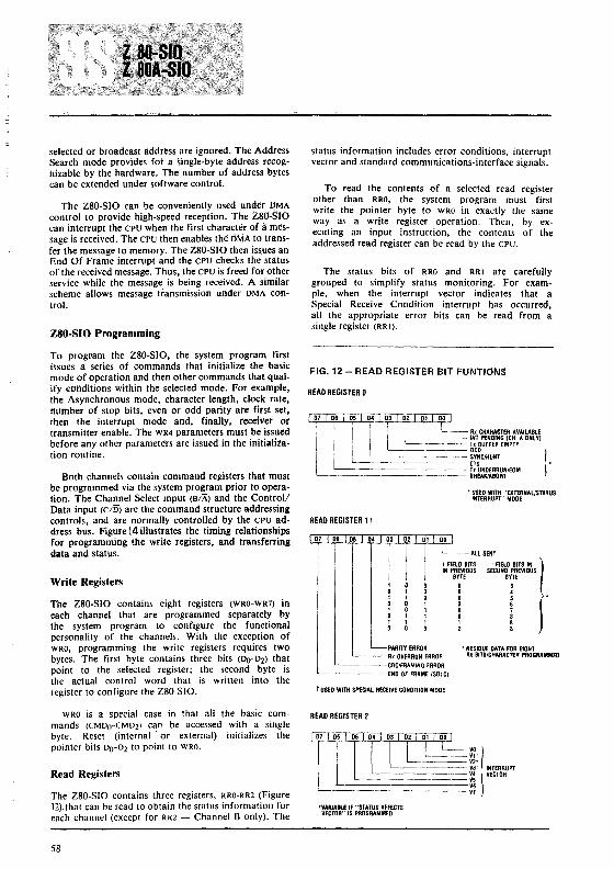
selected or broadcast address are ignored. The AddressSearch mode provides fot a single-byte address recognizable by the hardware. The number of address bytescan be extended under software control.
The Z80-S10 can be conveniently used under DMAcontrol to provide high-speed reception. The tSO-SIOcan interrupt the CPU when the first character of amessage is received. The CPU then enables the oMA to transfer the message to memory. The Z80-S10 then is~ues anEnd Of Frame interrupt and the CPU checks the statusof the received message. Thus, the CPU is freed for otherservice while the message is being received. A similarscheme allows message transmission under OMA control.
Z80·SIO Programming
status information includes error conditions, interruptvector and standard communications-interface signals.
To read the contents of a selected read registerother than RRO, the system program must firstwrite the pointer byte to WRO in exactly the sameway as a write register operation. Then, by executing an input instruction, the contents of theaddressed read register can be read by the CPU.
The status bits of RRO and RRI ate carefullygrouped to simplify status monitoring. For example, when the interrupt vector indicates that aSpecial Receive Condition interrupt has occurred,all the appropriate error bits can be read from asingle register (RRI).
PARITY ERROR • RESIDUE DATA FOR EIGHTR, OVERRUN ERROR R' BITS/CHARACTER PROGRAMMED
'------CRC/FRAMING ERROR'-------END OF FRAME (SDLC)
t USl:D WITH SPECIAL RECEIVE CONDInON MODE
--All SENT
I FIELD 81TS I FIELD 81TS INIIN PREVIOUS SECOND PREVIOUS8m 8mo 3o 4o 5·o 6o 7o 81 82 8
07 06 05 04
• USED WITH "EXTERNAUSTATUSINTERRUPT" MOOE
07 06
'-----II:TC~~~~~E~~.V:Ili1.~~~----- T, 8UFFER EMPTY
'----------- DCD'---------- SYNC/HUNT
'------------- CTSL--============ ~~~~l~~~/EOM
FIG. 12 - READ REGISTER BIT FUNTIONS
READ REGISTER 1t
READ REGISTER 0
80th channels contain command registers that mustbe programmed via the system program prior to operation. The Channel Select input (B/A) and the ControllData input (C/O) are the command structure addressingcontrols, and are normally controlled by the CPU address bus. Figure 14 illustrates the timing relationshipsfor programming the write registers, and transferringdata and status.
To prog~am the Z80-SI0, the system program firstissues a series of commands that initialize the basicmode of operation and then other commands that qualify cuftditions within the selected mode. For example,the Asynchronous mode, character length, clock rate,l1umber of stop bits, even or odd parity are first set,then the interrupt mode and, finally, receiver ortransmitter enable. The WR4 parameters must be issuedbefore any other parameters are issued in the initialization routine.
The Z80-S10 contains eight registers (WRO-WR7) ineach channel that are programmed separately bythe system program to configure the functionalpersonality of the channels. With the exception ofWRO, programming the write registers requires twobytes. The first byte contains three bits (00-02) thatpoint to the selected register; the second byte isthe actual control word that is written into theregister to configure the Z80-SI0.
Write Registers
WRO is a special case in that all the basic commands (CMOo-CM02) can be accessed with a singlebyte. Reset (internal or external) initializes thepointer bits 00-02 to point to WRO.
Read Registers
The Z80-S10 contains three registers, RRO-RR2 (Figure12).that can be read to obtain the status information foreach channel (except for RR2 Channel 8 only). The
READ REGISTER 2
W~~~:IINTERRUPT\ VECTOR
'YARlAIII.E IF "STATUS AFFECTSVECTOR" IS PROGRAMMED
58

FIG. 13 - WRITE REGISTER BIT FUNCTIOI;\IS
Z-80 SIO Programming
WRITE REGISTER 0
I 01 I 06 I 05 I 04 I 03 I 02 I 01 I DO ,
~ ~ lo 0 1o 1 0o 1 11 0 01 0 11 1 01 1 1
REGISTER 0REGISTER 1REGISTER 2REGISTER 3REGISTER 4REGISTER 5REGISTER 6REGISTER 7
WRITE REGISTER 4
PARITY ENABLE.- PARITY EVEN/Iili(j
SYNC MODES ENABLE1 STOP BIT/CHARACTER1'I, STOP BITS/CHARACTER2 STOP BITS/CHARACTER
01 06
NUll CODE
~~~~l:~T~Tst~%~ INTERRUPTSCHANNEL RESETENABLE INT ON NEXT Rx CHARACTERRESET TxlNT PENDINGERROR RESETRETURN FROM INT (CH-A ONLY)
NUll CODERESET Rx CRC CHECKERRESET Tx CRC GENERATORRESET Tx UNDERRUN/EDM lATCH
WRITE REGISTER 1
05 I D41D3U2j~
~I r [--~--- m~!:E~:;tgTEs VECTOR(CH B ONLY)
o 0 Rx INT DISABLEo 1 Rx INT ON FIRST CHARACTER I1 OINT ON All Rx CHARACTERS lPARITY AFFECTt VECTOR) •1 1 ~~~?~Rfll Rx CHARACTERS PARITY DOES NOT AFFECT
• OR ON
~~~m ~MqION ~~~MON'------WAIT/READY ENABLE
WRITE REGISTER 2 (CHANNEL B ONLY)
I INTERRUPTlVECTOR
WRITE REGISTER 3
Rx ENABLE'----- SYNC CHARACTER lOAD INHIBIT
'-------ADDRESS SEARCH MODE (SDlC)----Rx CRC ENABLE
'----------ENTER HUNT PHASE'--------- ------AUTO ENABLES
Rx 5 BITS/CHARACTERRx 7 BITS/CHARACTERRx 6 BITS/CHARACTERRx 8 BITS/CHARACTER
8 BIT SYNC CHARACTER16 BIT SYNC CHARACTERSDLC MODE (01111110 FLAG)EXTERNAL SYNC MODE
Xl CLOCK MODEX16 CLOCK MODEX32 CLOCK MODEX64 CLOCK MODE
WRITE REGISTER 5
Tx CRC ENABLERTSSDLC/CRC-16
'-------------- Tx ENABLEL- -----•.-------- SEND BREAK
i~ ~ ::i~/b~~ri_mJ~HARACTER11 6 BITS/CHARACTERTx 8 BITS/CHARACTER
WRITE REGISTER 6
- SYNC BIT 0 ~SYNC BIT 1
._- SYNC BIT 2SYNC BIT 3SYNC BI1 4 )SYNC BIT 5SYNC BIT 6SYNC BI11
-ALSO SDLC ADDRESS FIELD
WRITE REGISTER 7
SYNC BIT 8
1SYNC BIT 9SYNC BIT 10SYNC BIT 1,1
--. SYNC BIT 12 •SYNC BIT 13SYNC BIT 14
- SYNC BIT 15
•FOR SOLC IT MUST BE PROGRAMMEDTO "01111110" FOR FLAG RECOGNITION
59

Synchronous Modes (continued)
Z-80 SIO TimingTiming
Read Cycle. The timing signals generated by aZBO-CPU input instruction to read a Data or Status bytefrom the ZBO-SIO are illustrated in Figure 14a.
Write Cycle. Figure 14b illustrates the timing and datasignals generated by a ZBO-CPU output instruction towrite a Data or Control byte into the ZBO-SIO.
FIG. 14a - READ CYCLE FIG. 14b - WRITE CYCLE
RD
Ml
DATA DATA ____----'X'-__IN__>c=
Interrupt Acknowledge Cycle. After receiving anInterrupt Request signal (INT pulled Low), theZBO-CPU sends an Interrupt Acknowledge signal(Mi and IORQ both Low). The daisy-chained interrupt circuits determine the highest priority interrupt requestor. The lEI of the highest priorityperipheral is terminated High. For any peripheralthat has no interrupt pending or under service,lEO =lEt. Any peripheral that does have an interruptpending or under service forces its lEO Low.
To insure stable conditions in the daisy chain,all interrupt status signals are prevented fromchanging while Mi is Low. When IORQ is Low, thehighest priority interrupt requestor (the one withlEI High) places its interrupt vector on the data busand sets its internal interrupt-under-service latch.
Return From Interrupt Cycle. Normally, theZBO-CPU issues a RETI (RETurn from Interrupt) instruction at the end of an interrupt service routine.RET! is a 2-byte opcode (ED-4D) that resets theinterrupt-under-service latch to terminate the interrupt that has just been processed. This is accomplished by manipulating the daisy chain in thefollowing way.
The normal daisy chain operation can be used todetect a pending interrupt; however, it cannot distinguish between an interrupt under service and a pendingunacknowledged interrupt of a higher priority. Whenever "ED" is decoded. the daisy chain is modified byforcing High the lEO of any interrupt that has not yetbeen acknowledged. Thus the daisy chain identifies thedevice presently under service as the only one with an lEI
FIG. 14c INTERRUPT ACKNOWLEDGE CYCLE FIG. 14d - RETURN FROM INTERRUPT CYCLE
DATA -----.---~---
Mi ~_----.r--
lORD ~ /
I1,---------------'-'
lEI
RD
lED
M1
'I'
'\.------------~RDlEI ~-:'~~~ ~ 7
60
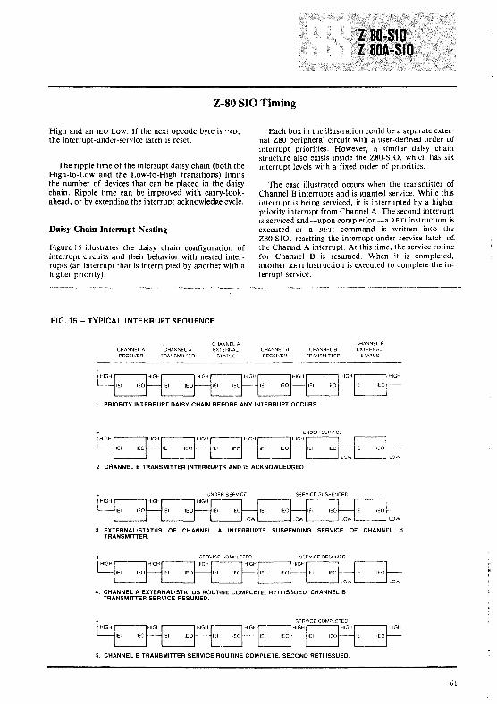
Z-80 SIO Timing
High and an lEO Low. If the next opcode byte is "4D,'
the interrupt-under-service latch is reset.
The ripple time of the interrupt daisy chain (both theHigh-to-Low and the Low-to-High transitions) limitsthe number of devices that can be placed in the daisychain. Ripple time canb~ improved with carry-lookahead, or by extending the interrupt acknowledge cycle.
Daisy Chain Interrupt Nesting
Figure 15 illustrates the daisy chain configuration ofinterrupt circuits and their behavior with nested interrupts (an interrupt that is interrupted by another with ahigher priority).
FIG. 15 - TYPICAL INTERRUPT SEQUENCE
Each box in the illustration could be a separate external Z80 peripheral circuit with a user-defined order ofinterrupt priorities. However, a similar daisy chainstructure also exists inside the Z80-SIO, which has sixinterrupt levels with a fixed order of priorities.
The case illustrated occurs when the transmitter ofChannel B interrupts and is granted service. While thisinterrupt is being serviced, it is interrupted by a higherpriority interrupt from Channel A. The second interruptis serviced and-·~upon completion-a RETI instruction isexecuted or a RETI command is written into theZ80-SIO, resetting the interrupt-under-service latch of.the Channel A interrupt. At this time, the service rotinefor Channel B is resumed. When it is completed,another RETI instruction is executed to complete the interrupt service.
CHANNEL ARECEIVER
CHANNEL ATRANSMITTER
CHANNEL AEXTERNAL
STATUSCHANNEL BRECEIVER
CHANNEL BTRANSMITTER
CHANNEL BEXTERNAL
STATUS
1. PRIORITY INTERRUPT DAISY CHAIN BEFORE ANY INTERRUPT OCCURS
2. CHANNEL B TRANSMITTER INTERRUPTS AND IS ACKNOWLEDGED.
3. EXTERNAUSTATUS OF CHANNEL A INTERRUPTS SUSPENDING SERVICE OF CtiANNEL BTRANSMITTER.
IEI-:L-=:JlOW
4. CHANNEL A EXTERNAL/STATUS ROUTINE COMPLETE RETI ISSUED. CHANNEL BTRANSMITTER SERVICE RESUMED.
5. CHANNEL B TRANSMITTER SERVICE ROUTINE COMPLETE, SECOND RETI ISSUED
61

Electrical Characteristics
FIG. 16 - TYPICAL INTERRUPT SEQUENCE
AC CharacteristicsTA=O°C, Vee= +5V, ±507o
lEO
laO-SIO Z80A-SIO
Signal Symbol Parameter Min MOl Min Ma' Unit
Clock PerIod 400 4000 250 4000 nsClock Pulse Width clock HIGH 170 2000 105 2000 nsClock Pulse Width clock lOW '70 2000 105 2000 ns
1.1, Clock Rise and Fall Times 0 30 0 30 ns
'" Any Unspecified Hot! Time for setup limes 0 0 nsspeof,ed below
CE irA I",ICSI ContrOl SIgnal Setup Time 10 nsJng edge of '60CD lORa l/J dunng Read or Wnte Cycle
lo ..~(O) Data OulPUl Delay from uSing edge 01 ih dUring 240 220Read Cycle
15 ,.\(0) Data Setup Time to rlsmg edge 01 dl dUring 50 50
00 .0. Wnleor Ml Cycle'n,(O) Data Outpul Detay from falling edge 01 tOAD 340 '60
dUring INTA CYCle1,(0) Delay fa Floallng Bus lOUlpUl bufler disable lime) 230 110
lEI Isl1EIl fEI Setup Time 10 falling edge of IORO dutlng 200 '40INTA Cycle
'0..(10) lEO Delay Time from riSing edge 01 lEI '50 '00(aller ED decode)
lEa 10d10) lEO Delay Time Irom f?lfJng edge 01 lEI '50 '00 ns10",(10) lEO Delay Time from failing edge of M1 (lnlerrUpl 300 '90 ns
occurnng lust pnor 10Ml)
M' I~,.~{Ml) Ml Selup Time 10 riSing edge of dJ dUring INTA 90or Ml Cycle
t~)RDI 240
·If WAIT from Ihe- 510 is 10 be UM'd. cr. IORQ. C/O and M1 mU51 be vaJid for as long a5 Ihe- Wail condilion is 10 peni51.
62

Electrical Characteristics
AC Characteristics
TID
'.~ N
.. II ITrH'. .')-
_,,,m'U
{""l,·UU' 'I
~---lcIR.CI---""
1'----"'11£ ARST BIT OFDATA CHARACTER
-'.IRCll- -IwIRCHI-
flIT
R.O
10R.C ISYI ~ 100 ns
1'---+---'1 "----------
NOTES,
I. Th~ SYNC input must be driY~n Low on the- risingedgr orR;(: delayed two complde clock cycles (rom the last bit oCtile!lync character
2. Dafa chancter u5C'mbly ~gins on thl! next Rttein Clock cycle after the last bit of the sync chancter is rttt'ivled
ZBll·SIO ZBllA·SIO
Signa' Symbol Paramet.r Min M.. Min M.. Unit
10 13 10 13iNT' 5 9 5 9
CTSA CTSBI,(PHI MJOtmum HIGH Pulse Width lor latching Slale 200
Inlo register and generating InterruptOCQA, 5C51i, Iw(PL) Minimum LOW Pulse Width lor latching slale 200SYNCA SYNCB
¢ penods
SYNCA SYNCB
400 400 nsTxCA rxes 180 180 ns
180 180 ns
TxDATxOBt lo(TxD) TxD OUlput Delay Irom falhng Edge 01 he 400 300(xl Clock Mode)
'dR><C) Receive ClOCk Penod 400 400 nsRXCA AxeS I,(ACH) Receive Clock Pulse Width clock HIGH 180 180 ns
I,(ACL) Receive Clock Pulse Wldlh clock LOW 180 180 ns
0 0 ns,40 140 ns
tl~od~5. th~ sY5t~m clock ($) rat~ must be at l~as( 4.5 tim~s th~ maximum data rateRESET must be activ~ a minimum of on~ complete eb cycle
63

Electrical Characteristics
AC Characteristics
iIll
, '_OIC_�w_._A'==u= lo~IWAI
WAIT FUNCTION
.~'READY FUNCTION
IoIC{WfR) WAIT/READY Delay Tune Irom lORD or CE InW8ltMode
IoH<b{W/R) WAIT/READY Delay Til"" lrom lal~ng edge 01 4>WAIT/READY HIGH Wart Mode
IoFbIW/R) WAIT/READY Delay Tome lrom nsong edge 01 FbCData Bll. Ready Mode
toTx(W/R) WAIT/READY Delay Time from cantero' Transrr;lllData Bd, Ready Mode
Ioltb(W/R) ~ Delay Tltne Irom nSlng edge 01 q,WAi'i'iR'EADY tOW Ready Mode
Slgn.' Symbol Parametar
iNT Delay TIme from nSlng edge of (j,
Z80-SIO Z80A-SlO
Min Min Max
200 200
300 210
150 130
10 13
120 '20
Unit
DC CharacteristicsTA =O°C to 70°C, Vee= + 5V, ±5OJo
CapacitanceTA=25°C, f= 1 MHz
R,21)("
FROM
~:f:~TO-<I>---<~_~--I<I----'
250,·A
64

Package Information
Dl DO D, DO Dl DO
D3 02 D3 D2 D3 02
DS D4 DS D4 DS D4
D7 06 D7 D6 D7 D6
iiiT _iOiiii iiiT iOiiii iiiT IDAD
CE lEI _CE lEI CElED BiA lED BiA lED siA
ii Cllt ii Cllt ii Cllt
VDD 1m VOD 1m VDD 1m
'IV7Il1lYA 10 _DND WiRoYA DND W'i1iiivl DNDlSD·SIOID
SYNCA 11 WIl'ffi WRiiYii SYNCA WliiiYBAIDA 12 SYiiCir SYiiCir A.DA
13 R.DB RICA RIDB A.CA iiiCi
TIci 14 iiiTiC8 hCA_ iiiCi T.CA fiCa
TlDA 15 hDB hOA hce TlDA TlDB
16 DTRB DTRA TlDB _iiTiiB17 iffiij RTSA RTse RffiIS ffiij CTSA ffiij CTSA CTse
19 jjffi iiCOA DCDB iiCOA oCiii2D iiEffi iiEffi mIT
MECHANICAL DATA (dimensions in mm)
40-PIN CERAMIC DUAL IN-LINE SLAM PACKAGE
~~M5080I. 11.38 l
[;:m~:Et~ORDERING NUMBERS:
Z80-SIO 01 for dual in-line ceramic slam packageZ80-8IO Bl for dual in-line plastic packageZ80A-SIO 01 for dual in-line ceramic slam packageZ80A-SIO Bl for dual in-line plastic package
40-PIN PLASTIC DUAL IN-LINE PACKAGE
52"'"
)
6S


MUSINTEGRATEDCIRCUITS
General Description
The Z80-SIO (Serial Input/Output) is a single-channelmulti-function peripheral component designed to satisfya wide variety of serial data communications requirements in microcomputer systems. Its basic function is aserial-to-parallel, parallel-to-serial converter/controller,but-within that role-it is configurable by systemssoftware so its "personality" can be optimized for agiven serial data communications application.
The Z80-SIO is capable of handling asynchronousformats, synchronous byte-oriented protocols such asIBM Bisync, and synchronous bit-oriented protocolssuch as HDLC and SDLe. This versatile device can alsobe used to support virtually any other serial protocol forapplications other than data communications (cassetteor floppy disk interfaces, for example).
The Z80-SIO can generate and check CRC codes inany synchronous mode and can be programmed tocheck data integrity in various modes. The device alsohas facilities for modem controls in both channels. Inapplications where these controls are not needed, themodem controls can be used for general-purpose I/O.
FIG. 17 - SIO/9 BLOCK DIAGRAM
Product Specification
Structure
II N-channel silicon-gate depletion-load technology
II 4O-pin DIP
II Single 5V power supply
.. Single-phase 5V clock
II All inputs and outputs TTL compatible
FeaturesII One full-duplex channel
.. Data rates in synchronous or isosynchronous modes:
• O-SooK bits/second with 2.5 MHz system clockrate
• 0-8ooK bits/second with 4.0 MHz system clockrate
II Receiver data registers quadruply buffered; transmitter doubly buffered.
.. Asynchronous features:
• 5, 6, 7 or 8 bits/character• I, 1V2 or 2 stop bits• Even, odd or no parity
DATA
CONTROL
>Q","'z ....·ou
111 INTERNALCONTROL
LOGIC
INTERRUPTCONTROL
LINES
CHANNEL AREADIWRITEREGISTERS
f SERIAL DATA
~ CHANNEL CLOCKS
svm:W1iIT1IfEAIW
MODEM OROTHERCONTROLS
67

• x I, X 16, x32 and x64 clock modes• Break generation and detection• Parity, overrun and framing error detection
• Binary synchronous features:• Internal or external character synchronization• One or two sync characters in separate registers• Automatic sync character insertion/deletion• CRC generation and checking
• HDLC and SDLC features:• Abort sequence generation and detection• Automatic zero insertion and deletion• Automatic flag insertion between messages• Address field recognition• Support for one to eight bits/character• Valid receive messages protected from overrun• CRC generation and checking
,~ r DDD,D,
""1DJIU. D,D.D.D,
Ci
.OD {Rim
COIUROt ..fROM l"'iiifo
"DO NOTCONNECT
~~:;:[T{iiii
'""D
FUNCTIONAL PIN CONFIGURATION
• Interrupt features:• Daisy-chain interrupt logic provides automatic
interrupt vectoring with no external logic
• Programmable interrupt vector• Status Affects Interrupt Vector mode for fast
interrupt processing
• CRC-16 or CRC-CCITT block frame check
• Modem control inputs and outputs
• Modem status can be monitored
Write Register 2 (interrupt vector) and the StatusAffects Vector bit in Write Register I are, however, stillprogrammed by selecting Channel B with the B/A selectinput. All other bits in Write Register I or Channel Bmust be programmed to O.
0, DO
03 0,
0, 0,
0, 06
iii iOiiilEI CE
lED ,IAii1~, C/~
VDD Il1I
Wi1im
iiiCifiU; }oo_ii'fiiA 00"'.iffiArnADEDi
ifffiT
PACKAGE CONFIGURATION
Ordering Information
Z80A-SIO/9 0 I = 4 MHz maximum clock rate,ceramic package, O°C to + 70°Ctemperature range
Z80A-SIO/9 BI = 4 MHz maximum clock rate,plastic package, O°C to + 70°Ctemperature range
68
Z80-SI0/9 B1
2.5 MHz maximum clock rate,ceramic package, O°C to +70°Ctemperature range
= 2.5 MHz maximum clock rate,plastic package, O°C to + 70°Ctemperature range
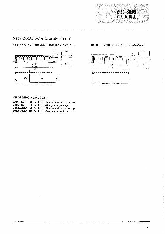
MECHANICAL DATA (dimensions in mm)
40-PIN CERAMIC DUAL IN-LINE SLAM PACKAGE 40-PIN PLASTIC DUAL IN-LINE PACKAGE
I . 11.38 I
[::~ Et:::::[J~~"48.26
5080
ORDERING NUMBERS:
Z80-SIO/9 Dl for dual in-line ceramic slam packageZ80-SIO/9 Bl for dual in-line plastic packageZ80A-SIO/9 Dl for dual in-line ceramic slam packageZ80A-SIO/9 Bl for dual in-line plastic package
69


MUSINTEGRATEDCIRCUITS
Features
• Two independent full-duplex channels with separatemodem controls. Modem status can be monitored.
• Receiver data registers are quadruply buffered; thetransmitter is doubly buffered.
• Interrupt features include a programmable interruptvector, a "status affects vector" mode for fastinterrupt processing, and the standard Z80 peripheraldaisy-chain interrupt structure that provides automaticinterrrupt vectoring with no external logic.
• [n xl clock mode, data rates are 0 to SOOK bits/secondwith a 2.5 MHz clock, or 0 to 800K bits/second witha 4.0 MHz clock.
• Programmable options include 1, 1 ~ or 2 stop bits;even, odd or no parity; and xl, x 16, x32 and x64 clockmodes,
• Break generation and detection as well as parity-,overrun-and framing-error detection are available.
Product SpecificationDescription
The 280 DART (Dual-Channel AsynchronousReceiver/Transmitter) is a dual-channel multi-functionperipheral component that satisfies a wide variety ofasynchronous serial data communications requireme~ts
in micro-computer systems. The 280 DART is used as aserial-to-parallel, parallel-to-serial converter/controller inasynchronous applications. [n addition, the device alsoprovides modem controls for both channel. In applicationwhere modem controls are not needed, these lines can beused for general-purpose I/O.
SeS-ATES also offers the Z80 SIO, a more versatiledevice that provides synchronous (Bisync, HDLC and SDLe)as well as asynchronous operation).
The Z80 DART is fabricated with n-channelsilicon-gate depletion-load technology, and is packagedin a 40-pin plastic or ceramic D[P.
Fig. 1 - PIN FUNCTION Fig. 2 - PIN ASSIGNMENTS
D 1 Do
D3 D2
CPU D5 Df,
DATA BU5 D7 D6
I MODE:M
CH-A iNT 10RO
lEI IT
lEO Jf, BIA
rONTROl M1 33 C/O
VDDZ80 -DART
32 R5
CONTROLW/RDYA 10 Z80A-DART 31
GND
FROM CPU RIA 30 WRDYB
RxDA 12 29 RIB
RxCA 28 RxDB
CH-B TxCA If, 27 R xTxCB
TxDA 15 26 TxOB
DTRA 16 25 DTRB
RT5A 2f, RT'5BelSA 23 C158
DeDA 19 22 DCDB
.5VClK 20 21 RESET
GND ClK
5-4603
71

BIA. Channel A Or B Select (input, High selects Channel B),This input defines which channel is accessed during a datatransfer between the CPU and the Z80 DART,
C/O. Control Or Data Select (input, High selects Control)This input specifies the type of information (control ordata) transferred on the data bus between the CPU and theZ80 DART.
CE. Chip linable (input, active Low), A low at this inputenables the Z80 DART to accept command or data inputfrom the CPU during a write cycle, or to transmit datato the CPU during a read cycle.
CLK. System Clock (input), The Z80 DART uses thestandard Z80 single-phase system clock to synchronizeinternal signals.
CTSA, CTSB. Clear To Send (inputs. active Low). Whenprogrammed as Auto Enables,a Low on these inputs enablesthe respective transmitter. If not programmed as AutoEnables, these inputs may be programmed as generalpurpose inputs. Both inputs are Schmitt-trigger bufferedto accomodate slow-risetime signals,
Do-D7 • System Data Rus (bidirectional, 3-state) transfersdata and commands between the CPU and the Z80 DART,
DCDA, DCDB. Data Carrier Detect (inputs. active Low),These pins function as receiver enables if the Z80 DARTis programmed for Auto Enables; otherwise they may beused as general-purpose input pins. Both pins areSchmitt-trigger buffered.
Pin Description
MI ,Aftlelli»e Cycle Olle (input from Z80 CPU, active Low).When Mi and RD are both active. the Z80 CPU is fetchingan instruction from memory: when MI is active while(ORO is active. the Z80 DART accepts M I and 10RO asan interrupt aknowledge if the Z80 DART is the highestpriority device that has interrupted the Z80 CPU,
10RQ. 1111'11 t/Oll tI'lIt Rn/IH'St (input from CPU, activeLow). 10RO is used in conjunction with B/A. C/D, CE andRD to transfer commands and data between the CPU andthe Z80 DART When fE. RD and 10RO are all active,the channel selected by B/A transfers data to the CPU (aread operation), When CE and 10RO are active, but RDis inactive. the channel selected by B/A is written to by theCPU with either data or control information as specifiedby c/D,
RxCA, RxCB. Receil'er Clocks (inputs). Receive data issampled on the rising edge of RxC. The Receive Clocks maybe I. 16.3:'. or 64 times the data rate,
RD. I~etl" Cvcle SttltllS (input from CPU. active Low). IfRD is active: a memory or I/O read operation is in progress.
RxDA. RxDB. ReceilJe Dc1tc1 (inputs, active High),
RESET. Resl't {input. active Low), Disables both receiversand transmitters. forces TxDA and TxDB marking, forcesthe modem controls High and disables all interrupts,
RIA. RIB. Rill)! Illdictltor (inputs. Active Low). Theseinputs are similar to CTS and DCD. The Z80 DARTdetectes both logic level transitions and interrupts the CPU.When not used in switched-line applications. these inputscan be used as general··purpose inputs.
RTSA. RTSB. Re'llIest to Selld (outputs. active Low),DTRA, DTRB. Data 'j'erminc1l Rec1dy (outputs. active Low). When the RTS bit is set. the RTS output goes Low. WhenThese outputs follow the state programmed into the the RTS bit is reset. the output goes High after theDTR bit. They can also be programmed as general-purpose transmitter empties,outputs.
lEI. Interrupt Ellable /11 (input, active High) is used withlEO to form a priority daisy chain when there is morethan one interrupt-driven device. A High on this lineindicates that no other device of higher priority is beingserviced by a CPU interrupt service routine
lEO. Interrupt Enc1ble Out (output, active High). lEO isHigh only if lEI is High and the CPU is not servicing aninterrupt from this Z80 DART. Thus, this signal blockslower priority devices from interrupting while a higherpriority device is being serviced by its CPU interruptservice routine.
INT. Interrupt Request (output. open drain, active Low).When the Z80 DART is requesting an interrupt, itpulls INT Low.
72
TxCA. TxCB. h'lIlSlIlitter Clocks (inputs), TxD changes onthe falling of TxC. The Transmitter Clocks may be 1.16.3:'. or 64 times the data rate: however. the clock multiplierfor the transmitter and the receiver must be the same. TheTransmit Clock inputs are Schmitt-trigger buffered, Boththe Receiver and Transmitter Clocks may be driven by treZ80 CTC Counter Time Circuit for programmable baudrate generation
TxDA. TxDB. '!rtlIlSlllit D,lta (outputs, active High),
W/RDYA. W/RDYB, 1!'c1it/Retldv (outputs. open drainwhen programmed for Wait function, driven High and Lowwhen programmed for Ready function), Thesedual-purpose outputs may be programmed as Ready linesfor a DMA controller or as Wait lines that synchronize theCPU to the Z80 DART data rate. The reset state is opendrailL

Functional Description
The functional capabilities of the Z80 DART can bedescribed from two different points of view; as a datacommunications device, it transmits and receives serial data,and meets the requirements of asynchronous datacommunications protocols; as a Z80 family peripheral, itinteracts with the Z80 CPU and other Z80 peripheralcircuits, and shares the data, address and control buses, aswell as being a part of the Z80 interrupt structure. Asa peripheral to other microprocessor, the Z80 DARToffers valuable features such as non-vectored interrupts,polling and simple handshake capability.
The first part of the following functional descriptionintroduces Z80 DART data conununications capabilities;the second part describes the interaction between the CPUand the Z80 DART.
A more detailed explanation of Z80 DART operationcan be found in the Z80 SIO Teclmical Mallllal(Document Number 03-3033-01). Because this manualwas written for the 280 SIO, it contains informationabout synchronous as well as asynchronous operation.
Communications Capabilities. The Z80 DART providestwo independent full-duplex channels for use as anasynchronous receiver/transmitter. The following is a shortdescription of receiver/transmitter capabilities. For moredetails, refer to the Asynchronous Mode section of the
Z80 SIO Technical Manllel/. The Z80 DART offerstransmission and reception of five to eight bits percharacter, plus optional even or odd parity. Thetransmitter can supply one, one and a half or two stopbits per character and can provide a break output at anytime. The receiver break detection logic interrupts the CPUboth at the start and end of a received break. Reception isprotected from spikes by a transient spike rejectionmechanism that checks the signal one-half a bit timeafter a Low level is detected on the Receive Data inpuLIf the Low does not persist - as in the case of atransient the character assembly process is not started.
Framing enors and overrung errors are detected andbuffered together with the character on which theyoccurred. Vectored interrupts allow fast servicing ofinterrupting conditions using dedicated routines.Furthermore, a built-in checking process avoidsinterpreting a framing error as a new start bit: a framingerror results in the addition of one-half a bit time to thepoint at which the search for the next start bit is begun.
The Z80 DART does not require symmetric Transmitand Receive Clock signab a feature that allows it to beused with a Z80 CTC or any other clock source. Thetransmitter and receiver can handle data at a rate of I , 1/16,1/32 or 1/64 of the clock rate supplied to the Receive andTransmit Clock inputs. When using Channel B, the bit ratesfor transmit and receive operations must be the samebecause RxC and TxC are bonded together (RxTxCB).
Fig. 3 - BLOCK DIAGRAM
f SERIAL DATA
}CHANNEL CLOCKS
WAIT IREADY
IMODEM OROTHER CONTROLS
RIB
f SERIAL DATA
CHANNEL CLOCK
WAIT IREADY
--IMODEM OROTHER CONTROLS
RiA
5-4626
CONTROL ---y L...__---I
DATA
73

I/O Interface Capabilities. The Z80 DART offers thechoice of Polling, Interrupt (vectored or non-vectored) andBlock Transfer modes to transfer data, status and controlinformation to and from the CPU. The Block Transfermode can be implemented under CPU or DMA controL
POLLING There are no interrupts in the Polled mode.Status registers RRO and RRI are updated at appropriatetimes for each function being performed. All the interruptmodes of the Z80 DART must be disabled to operate thedevice in a Polled environmenL
While in its Polling sequence, the CPU examines thestatus contained in RRO for each channeL the RRO statusbits serve as an acknowledge to the Poll inquiry. The twoRRO status bits Do and D2 indicate that a data transfer isneeded. The status also indicates Error or other specialstatus conditions (see "Z80 DART Progranuning").The Special Receive Condition status contained in RR Idoes not have to b~ read in a Polling sequence becausethe status bits in RRI are accompanied by a ReceiveCharacter Available status in RRO.
INTERR UPTS The Z80 DART offers an elaborateinterrupt scheme that provides fast interrupt response inreal-time applications. As a member of the Z80 family.the Z80 DART can be daisy-chained along with otherZ80 peripherals for peripheral interrupt-priorityresolution. In addition, the internal interrupts of theZ80 DART are nested to prioritize the various interruptsgenerated by Channels A and B. Channel B registers WR2and RR2 contain the interrupt vector that points to aninterrupt service routine in the memory .. To eliminate thenecessity of writing a status analysis routine. the Z80DART can modify the interrupt vector in RR2 so it pointsdirectly to one of eight interrupt service routines. This isdone under program control by setting a program bit(WRI, D2 ) in Channel B called "Status Affects Vector"When tltis bit is set, the interrupt vector in RR2 is modifiedaccording to the assigned priority of the variousinterrupting conditions.
Transmit interrupts, Receive interrupts and External/Status interrupts are the main sources of interrupts .. Eachinterrupts source is enabled under program control withChannel A having a higher priority than Channel B, andwith Receiver, Transmit and External/Status interruptsprioritized in that order within cach channeL When theTransmit interrupt is enabled, the CPU is interrupted by thetransmit buffer [JeW/Hill)! empty. (This implies that thetransmitter must have had a data character written into itso it can become empty.) When enabled, the receiver caninterrupt the CPU in one of three ways:
• Interrupt on the first received character
• Interrupt on all received characters
• Interrupt on a Special Receive condition
Interrupt On First Character is typically used with theBlock Transfer mode. Interrupt On All Receive Characters
74
Functional Description (continued)
can optionally modify the interrupt vector in the event ofa parity errOL The Special Receive Condition interruptcan occur on a character basis. The Special Receivecondition can cause an interrupt only if the Interrupt OnFirst Receive Character or Interrupt On All ReceiveCharacters mode is selected. In Interrupt On First ReceiveCharacter, an interrupt can occur from Special Receiveconditions (except Parity Error) after the first receivecharacter interrupt (example: Receive Overrun interrupt).
The main function of the External/Status interrupt is tomonitor the signal transitions of the CTS, DCD and RT pins;however. an External/Status interrupt is also caused by thedetection of a Break sequence in the data stream. Theinterrupt caused by the Break seq uence has a special featurethat allows the Z80 DART to interrupt when the Breaksequence is detected or terminated. This feature facilitatesthe proper termination of the current message, correctinitialization of the next message, and the accurate timingof the Break condition
C!'('1I>.111 /lloe}\ lRLYS1J:R The Z80 DARTprovides a Block Transfer mode to accomodate CPU blocktransfer functions and DMA block transfers (Z80 DMA orother designs) The Block Transfer mode uses the W/RDYoutput in conjunction with the Wait/Ready bits of WriteRegister I The W/RDY output can be defined undersoftware control as a Wait line in the CPU Block Transfermode or as a Ready line in the DMA Block Transfer mode
To a DMA controller. the Z80 DART Ready outputindicates that the Z80 DART is ready to transfer data toor from memory. To the CPU. the Wait output indicatesthat the ZRO DART is not ready to transfer data therebyrequestiLlg the CPU to extend the I/O cycle.
Intenlal Architecture
The device internal structure includes a Z80 CPUinterface, internal control and interrupt logic. and twofull-duplex channels Each channel contains read and writeregisters. and discrete control and status logic that providesthe interface to modems or other ex ternal devices
The read and write register group includes five 8-bitcontrol registers and two status registers. The interruptvector is written into an additional 8-bit register (WriteRegister 2) in Channel B that may be read through ReadRegister 2 in Channel B The registers for both channels arcdesignated as follows:
WRO-WR5 Write Registers 0 through 5RRO-RR2 Read Registers 0 through 2
The bit assignment and functional grouping of eachregister is configured to simplify and organize theprogramming process.

Intenlal Architecture (continued)
Data Path. The transmit and receive data path illustratedfor Channel A in Figure 4 is identical for both channels.The receiver has three 8-bit buffer registers in a FIFOarrangement in addition to the 8-bit receive shift register.This scheme creates additional time for the CPU to servicea Receive Character Available interrupt in a high-·speed datatransfer.
The logic for both channels provides formats, bitsynchronization and validation for data transferred to andfrom the channel interface. The modem control inputsClear to Send (CTS). Data Carrier Detect (DCD) and RingIndicator (RI) are monitored by the control logic underprogram control. All the modem control signals are generalpurpose in nature and can be used for functions other thanmodem control. The transmitter has an 8-bit transmit data register that
For automatic interrupt vectoring, the interrupt control is loaded from the internal data bus, and a 9-bit transmitlogic determines which channel and which device within the shift register that is loaded from the transmit data register.channel has the highest priority. Priority is fixed withChannel A assigned a higher priority than Channel B;Receive, Transm,it and External/Status interrupts areprioritized in that order within each channel.
Fig. 4 - DATA PATH
INTERNAL DATA BUS
RXOA
RECEIVE
DATA
FIFO
l·BITDELAY
RECEIVE
ERROR
FIFO
11
RECEIJ''ERRORLOGIC
Read, Write and Interrupt TiIning
To insure stable conditions in the daisy chain, allinterrupt status signals are prevented from changing wIllIeMIis Low. When IORQ is Low, the highest priorityinterrupt requestor (the one with lEI High) places itsinterrupt vector on the data bus and sets its internalinterrupt-under-service latch.
Refer to the Z80 510 Technical Manual for additionaldetails on the interrupt daisy chain and interrupt nesting.
Read Cycle. The timing signals generated by a Z80 CPUinput instructions to read a Data or Status byte from theZ80 DART are illustrated in Figure Sa.
peripheral is terminated High. For any peripheral that hasno interrupt pending or under service, lEO lEI. Anyperipheral that does have an interrupt pending or underservice forces its lEO Low.
Write Cycle. Figure Sb illustrates the timing and data signalsgenerated by a Z80 CPU output instruction to write aData or Control byte into the Z80 DART.
Interrupt Acknowledge Cycle. After receiving an InterruptRequest signal (INT pulled Low), the Z80 CPU sends anInterrupt Acknowledge signal (Ml and IORQ both Low).
The daisy-chained interrupt circuits determine the highestpriority interrupt requestor. The lEI of the highest priority
75

Read, Write and Interrupt Timing (continued)
Return From Interrupt Cycle. Normally, the Z80 CPUissues an RETI (Return From Interrupt) instructions at theend of an interrupt service routine RETI is a 2-byteopcode (ED-4D) that resets the interrupt-under-servicelatch to terminate the interrupt that has just beenprocessed.
When used with other CPUs, the Z80 DART allows theuser to return from the interrupt cycle with a specialcommand called "Return From Interrupt" in Write Registeroof Channel A. This command is interpreted by the Z80DART in exactly the same way it would interpret an RET Icommand on the data bus
Fig. 5a - READ CYCLE Fig. 5b - WRITE CYCLE
M1 ----------------- M1 ------------------
AD ------------------
IORO ''-..\ /
DATA ....X'- I_N x==
T,T,
OUT
TwT,
DATA -----------{
CE oJ '--I- ..J '- _
T,
CLOCK
Fig. 5c - INTERRUPT ACKNOWLEDGE CYCLE Fig. 5d - RETURN FROM INTERRUPT CYCLE
M1 ~'- ---J!
"--.!
CLOCK
T, T, TW TW T, T.
CLOCK
M1
RD
AD -----------------
lEI ========_7DATA -----------( VECTOR >----
lEO .J..i:r-
76

Z80 DART Programming
To program the Z80 DART, the system program firstissues a series of commands that initialize the basic modeand then other commands that qualify conditions withinthe selected mode. For example, the character length, clockrate, number of stop bits, even or odd parity are first set,then the Interrupt mode and, finally, receiver or transmitterenable.
Both channels contain command registers that must beprogrammed via the system program prior to operation ..Th~Channel Select input (B/A) and the Control/Data input(C/O) are the command structure addressing controls, andare normally controlled by the CPU address bus.
Writer Registers. The Z80 DART contains six registers(WRO-WR5) in each channel that are programmedseparately by the system program to configure thefunctional personality of the channels (Figure 4). With theexception ofWRO, programming the write registers requirestwo bytes. The first byte contains three bits (00 -02 ) thatpoint to the selected register; the second byte is the actualcontrol word that is written into the register to configurethe Z80 DART.
WRO is a special case in that all the basic commands(CMDo-CMD2 ) can be accessed with a single byte Reset(Internal or external) initializes the pointer bits Do -02 topoint to WRO. This means that a register cannot be pointedto in the same operation as a channel reseL
Write Register Functions
Register pointers, initialization commands forthe various modes, etc.
WR I Transmit/Receive interrupt and data transfer modedefinition.
WR2 Interrupt vector (Channel B only)
WR3 Receive parameters and control
WR4 Transmit/Receive miscellaneous parameters andmodes
WR5 Transmit parameters and controls
Read Registers. The Z80 DART contains three registers(RRO-RR2) that can be read to obtain the statusinformation for each channel (except for RR2, whichapplies to Channel B only). The status information includeserror conditions, interrupt vector and standardcommunications-interface-signals.
To read the contents of a selected read register otherthan RRO, the system program must first write the pointerbyte to WRO in exactly the same way as a write registeroperations. Then, by executing an input instructions, thecontents of the addressed read register can be read by theCPU.
fhe status bits of RRO and RRI are carefully groupedto simplify status monitoring. For example, when theinterrupt vector indicates that a Special Receive Conditionsinterrupts has occurred, all the appropriate error bits can beread from a single register (RRI).
Read Register Functions
RRO Trasmit/Receiver buffer status, interrupt statusand external status
RRI Special Receive Condition status
RR2 Modified interrupt vector (Channel B only)
77

REGISTER 0REGISTER'REGISTER 2REGISTER 3REGISTER 4REGISTER 5
READ REGISTER I"
ALL SENT
NOT USED
'--- PARITY ERROR
L- Rx OVERRUN ERROR
L- FRAMING ERROR
L- NOT USED
WRITE REGISTER 0
10,10, I0, 10.10, I0, I0, 100 I
T-C!o 0 NULL CODeo 0 NOT USEDo 1 RESET EXT/STATUS INTERRUPTSo 1 CHANNEL RESET1 0 ENABLE INT ON NEXT Rx CHARACTER'0 RESET TxlNT PENDING1 1 ERROR RESET1 1 RETURN FROM INT (CH·A ONLY)
'-------NOT USED
WRITE REGISTER 2 (CHANNEL B ONLYl
10, I0.1 0, 10.10, I0, I0, IDo I
Ei[ ~~,~~"WRITE REGISTER 4
10,10,10, 10.10,10, ID,I~
ITT I L PARITY ENABLE
L PARITY EVENI5DiJ
o 0 NOT USEDo 1 1 STOP BIT/CHARACTER1 0 1 'IJ STOP BITSICHARACTER1 1 2 STOP BITS/CHARACTER
NOT USED
o 0 Xl CLOCK MODEo , X'6 CLOCK MODE, 0 X32 CLOCK MODE, 1 X64 CLOCK MODE
78
Z80 DART Read and Write Registers
READ REGISTER 0
I0, :0.1 0, '0,0310, I0, IDo I
EL~~'L Rx CHARACTER AVAILA,BLE
LINT PENDING (CH, A ONLY)
Tx BUFFER EMPTY
DCD }RIUSED WITH "EXTERNAlI
ers STATUS INTERRUPT"
NOT USED MODE
BREAK
READ REGISTER 2
I0, I0, I0, I0.1 0, I0, I0, IDo I
E~ug:;)V3"" INTERRUPTV4 VECTOR
'-V5
V6
V7
WRITE REGISTER 1
[~,~!.Qi,d.':2.J
[t~L EXT INTENABLE
L hiNT ENABLESTATUS AFFECTS VECTORICH B ONLY)
o 0 Ax INT DISABLE )o 1 Rx INT ON FIRST CHARACTER OR ON1 OiNT ON ALL Rx CHARACTERS (PARITY SPECIAL
AFFECTS VECTOR) RECEIVE1 liNT ON ALL Rx CHARACTERS (PARITY CONDITION
DOES NOT AFFECT VECTOR)
WAIT/READY ON R/T
'------ WAIT/READY FUNCTION
'------ WAIT/READY ENABLE
WRITE REGISTER 3
NOT USED
L- AUTO ENABLES
Rx 5 BITS/CHARACTERRx 7 BITS/CHARACTERRx 6 BITS/CHARACTERRx 8 BITS/CHARACTER
WRITE REGISTER 5
~~
lli~' L= :~:USED~NOTUSEO
Tx ENABLE
SEND BREAK
o 0 Tx 5 BITS (OR LESSj/CHARACTERo 1 Tx 7 BITS/CHARACTER1 0 Tx 6 BITS/CHARACTER1 1 Tx 8 BITS/CHARACTER
DTR
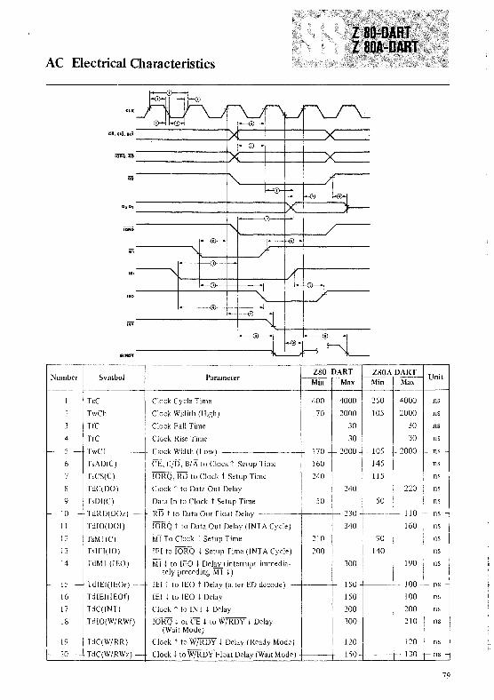
AC Electrical Characteristics
Ci, c/o, 8'A-~-------f./
IORQ,iffi
---------f./
DO·OJ
---------f------V
Number Symbol ParameterZ80 DART Z80A DART
UnitMin Max Min Max
I TcC Clock Cycle Time 400 4000 250 4000 ns
:: TwCh Clock Widith (High) 170 2000 105 2000 ns
3 HC Clock Fall Time 30 30 ns
4 IrC Clock Rise Time 30 30 ns
- 5 - TwC1 Clock Width (Low) 170 - r 2000 - 105 - 2000 ns -
6 TsAD(C) cr, C/O, B/A to Clock t Setup Time 160 145 ns
7 TsCS(C) IORQ, RD to Clock t Setup Time 240 115 ns
8 TdC(DO) Clock t to Data Out Delay 240 220 ns
9 IsDI(C) Data In to Clock t Setup Time 50 50 ns
- 10 - TdRD(DOz) - RD t to Data Out Float Delay 230 110 - ns -
11 TdIO(DOI) IORQ t to Data Out Delay (INTA Cycle) 340 160 ns
I:: TsM I(C) Mi To Clock t Setup Time 210 90 ns
13 TsIEI(IO) lEI to IORQ t Setup Time (iNT A Cycle) ::00 140 ns
14 TdMI (lEO) M1 t to lEO t Delay (interrupt immedia- 300 190 nstely preceding MIt)
15 - TdIEI(lEOr) - lEI t to lEO t Delay (after ED decode) 150 100 _. ns -
16 TdIEI(IEOf) lEI t to lEO t Delay 150 100 ns
17 TdC(INT) Clock t to INT t Delay 200 200 ns
18 TdIO(W/RWf) IORQ t or CE t to W/RDY t Delay 300 210 ns(Wait Mode)
19 TdC(W/RR) Clock t to W/RDY t Delay (Ready Mode) 120 120 ns
~ 20 - TdC(W/RWz) - Clock t to W/RDY Float Delay (Wait Mode) 150 130 f- ns -
79

AC Electrical Characteristics (continu~d)
ffi, iiCD, iii ~------I-------{G)>-----+I
ToD----+--
noD-------'
---'Unit ISymbol Parameter
Z80 DART Z80A DARTNwnber
Min Max Min Max
1 TwPh Pulse Width (High) 200 200 ns
2 TwPI Pulse Width (Low) 200 200 ns
3 TcTxC TxC Cycle Time 400 00 400 00 ns
4 TwTxCI TxC Width (Low) 180 00 180 00 ns
5 - TwTxCh - TxC Width (High) 180 _ 00_1-180 - _ 00 _ - ns
6 TdTxC(TxD) TxC t to TxD Delay 400 300 ns
7 TdTxC(WjRRf) TxC t to W/RDY t Delay (Ready Mode) 5 9 5 9 ClkPer.
8 TdTxC(INT) TxC t to INT t Delay 5 9 5 9 ClkPer.
9 TcRxC RxC Cycle Time 400 00 400 00 ns
10 TwRxCI- RxC Width (Low) 180 r-- 00 180 - - 00 - I- ns
11 TwRxCh RxC Width (High) 180 00 180 00 ns12 TsRxD(RxC) RxD to RxC l' Setup Time (xl Mode) 0 0 ns13 ThRxD(RxC) RxD Hold time (xl Mode) 140 140 ns
14 TdRxC(WfRRf) RxC t to WjRDY t Delay (Ready Mode) 10 13 10 13 Clk
TdRxC(INT) -tRxC t to INT t Delay
Per.I- 15 10 r- 13 - 10 t- 13- elk -
Per.In all modes, the Clock rate must be at least five times the maximum data rateifF.'SF.Tmust be active a minimum of one complete Clock Cycle
80

Absolute Maximum Ratings*
Voltages on all inputs and outputs with respect to GNDOperating Ambient TemperatureStorage Temperature
-03 to +7.0 VAs Specified in Ordering Information
-65 to + J50°C
• Stresse, greater than those listed under ;\b,olute Maximum Rating, may lau'e permanent damage to the devile I hi, i, a stress ratingonly: operation of the device at any londition ahove tho,e indicated in the operational ,el tiollS 01 the,e ,peciliLation, i, not implied) xpo,ure to ah,olute maximum ratin}'. londitions lor extended period, may allelt devile reliability
Standard Test Conditions
The characteristics below apply for the following standard test conditions.unless otherwise noted. All voltages arc referenced to GND. Positive currentflows into the referenced pin .. Standard conditions arc as follows:
• +4.75V ~ V« ~ +5.::5 V
• GND==OV
• r;\ as specified in Ordering Information
All ac parameters assume a load capacitance of 100 pF max. Timingreferences between two output signals assume a load difference of 50 pF max
DC Characteristics '1';\ 0°Ct070°C,Vcc +5V,±5%
21K
Symbol Parameter Min Max Unit lest Condition
V)L( Clock Input Low Voltage -0.3 +045 V
VIII(' Clock Input High Voltage V((-0.6 +5.5 V
Vll Input Low Voltage -0.3 +08 V
VIII Input High Voltage +:2.0 +5.5 V
VOL Output Low Voltage +04 V 101. == 20 mA
VOII Output High Voltage +24 V 1011 -250 I-' A
IL Input/3-State Output Leakage Current -10 +10 I-'A 04<V<24V1---..
IURI ) RI Pin Leakage Current -40 +10 I-'A 0.4 < V < 2.4V
1('( Power Supply Current 100 rnA
f?}1485
025
l~
MECHANICAL DATA (tlnnensions in mm)
40-PIN CERAMIC DUAL IN-LINE SLAM PACKAGE
~lm.1
~L3~?2t48.2650.80
ORDERING NUMBERS:
Z80 DART 01 for dual in-line ceramic packageZ80 DART BI for dual in-line plastic packageZ80A DART DI for dual in-line ceramic packageZ80A DART B1 for dual in-line plastic package
40-PIN PLASTIC DUAL IN-LINE PACKAGE
81

SGS·ATES GROUP OF COMPANIESINTERNATIONAL HEADQUARTERSSGS-ATES Componenti Elettronici SpAVia C. Olivetti 2 - 20041 Agrate Brianza - ItalyTeL: 039 - 65551Telex: 330131-330141
BENELUXSGS-ATES Componenti Elettronici SpABenelux Sales OfficeB- 1180 BruxellesWinston Churchill Avenue, 122TeL:02 3432439Telex: 24149 B
DENMARKSGS-ATES Scandinavia ABSales Office:2730 HerlevHerlev Torv 4TeL:02 948533Telex: 35411
EASTERN EUROPESGS-ATES Componenti Elettronici SpAExport Sales Office20041 Agrate Brianza - ItalyVia C Olivetti,2Tel: 039 - 6555287/6555207Telex: 330131-330141
FINLANDSales Office:SGS-ATES Scandinavia AB02210 Esbo 21Kiiiint6piiri 2Tel: 90 881395/6Telex: 123643
FRANCESGS-ATES France S.A75643 Paris Cedex 13Residence" Le Palatino"17, Avenue de ChoisyTel: 5842730Telex: 042 250938
GERMANYSGS-ATES Deutschland HalbleiterBauelemente GmbH8018 Grafing bei Mi.inchenHaidling 17Tel: 08092-691Telex: 05 27378Sales Offices:3012 LangenhagenHubertusstrasse 7TeL: 0511 -772075/7Telex: 09231958000 Mi.inchen 21Landsbergerstrasse 289TeL: 089 582047/8Telex: 05 2157848500 Ni.irnberg 15Parsifalstrasse 10TeL: 0911 - 49645/6Telex: 06262437000 Stuttgart 80Kalifenweg 45Tel:0711-713091/2Telex: 07 255545
HONG KONGSGS-ATES Singapore (Pte) Ltd.1329 Ocean CentreCanton Road, KowloonTel: 3 - 662625Telex: ESGIE HK 63906
ITALYSGS-ATES Componenti Elettronici SpADirezione Commerciale Italia20149 MilanoVia Correggio, 1/3Tel: 02 - 4695651Sales Offices:50127 FirenzeVia Giovanni Del Pian Dei Carpini 96/1Tel: 055 - 437776320149 MilanoVia Correggio 1/3TeL: 02 -469565100199 RomaPiazza Gondar, 11Tel: 06 - 8392848/831277710121 TorinoCorso G. Ferraris, 26Tel.: 011-531167
SINGAPORESGS-ATES Singapore (Pte) Ltd.Singapore 1231Lorong 4 & 6 - Toa PayohTel.: 2531411Telex: ESGIES RS 21412
SWEDENSGS-ATES Scandinavia AB19501 MiirstaBox 144Tel.: 0760 - 40120Telex: 042 10932
UNITED KINGDOMSGS-ATES (United Kindgom) Ltd.Aylesbury, BucksPlanar House, Walton StreetTeL: 0296 - 5977Telex: 041-83245
U.S.A.SGS-ATES Semiconductor CorporationScottsdale, AZ852517070 East 3rd AvenueTel: (602) 990-9553Telex: SGS ATES SCOT 165808Waltham, MA 02154240 Bear Hill RoadTeL: (617) 890-6688Telex: 923495 WHADes Plaines, I L 600182340 Des Plaines Ave Suite 309Tel: (312) 296-4035Telex: 282547
Information furnished is believer. to be accurate and reliable However, no responsibility is assumed for the consequences of its use nor forany infringement of patents or other rights of third parties which may result from its use. No license is granted by implication or otherwiseunder any patent or patent rights of SGS-ATES Specifications mentioned in this publication are subject to change without notice. Thispublication supersedes and suhstitutes all information previously supplied
SGS-ATES GROUP OF COMPANIESItaly - France - Germany - Singapore Sweden - United Kingdom - U.S.A.
1981 - Printed in Italy by permission of Zilog Inc.© SGS-ATES Componenti Elettronici SpA


![The Z80 Family Program Interrupt Structure [****]z80.info/zip/z80-interrupts_rewritten.pdf · THE Z80 FAMILY PROGRAM INTERRUPT STRUCTURE Visit Zilog at ! 20101110 / document version](https://static.documents.pub/doc/80x56/5b1542b67f8b9af15d8e48e6/the-z80-family-program-interrupt-structure-z80infozipz80-interrupts-.jpg)


