+ All Categories
Home > Documents > Zagar7.pdf

Zagar7.pdf

Date post: 10-Apr-2016
Category:
Upload: calvinyeoh
View: 9 times
Download: 1 times
Share this document with a friend
13
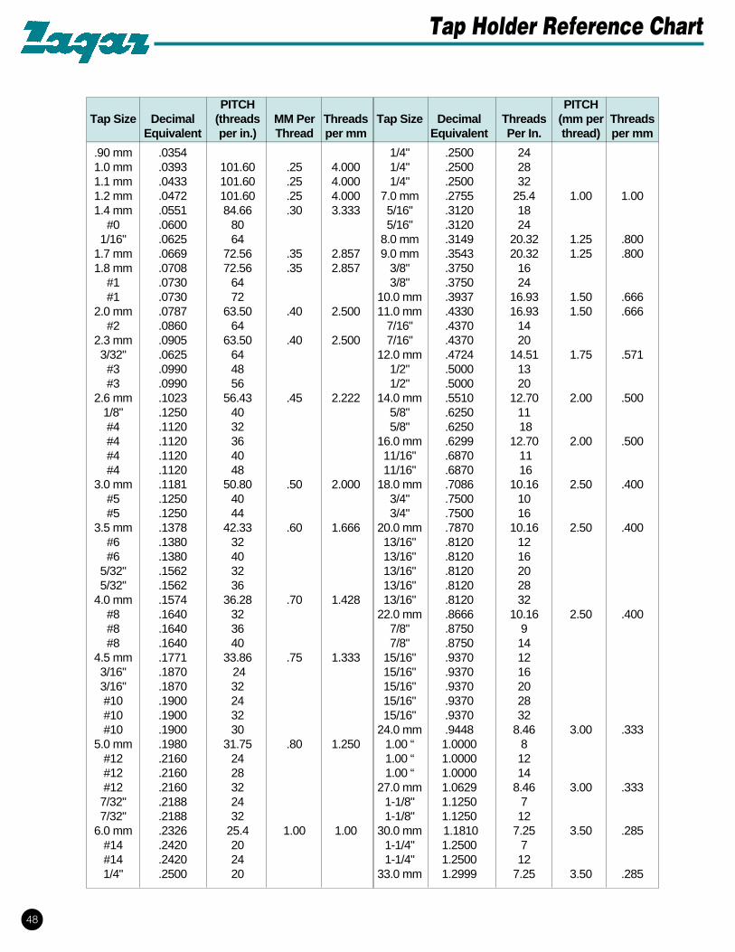
TAPS STANDARDS AND DIMENSIONS A metric tap with an ANSI shank uses the same Z-Lock holder as an inch tap with the same shank diameter. To determine spindle size for application. Select spindle size at minimum centers or use the basic spindle size. (Ref. Pages 6-7.) Use the charts on this page and the following to specify the holder number. Tap Shank Shank Size of Overall Size Dia. Length Square Length A B C D M0.9 2.5 (.098") 17 2.1 x 5 25 M1 18 M1.1 M1.2 18 25 M1.4 21 28 M1.6 24 32 M1.7 M1.8 2.5 (.098") 24 M2 2.8 (.110") 23 M2.2 M2.3 23 32 M2.5 26 36 M2.6 2.8 (.110") 26 2.1 x 5 36 M3 3.5 (.138") 26 2.7 x 6 36 M3.5 4.0 (.157") 29 3.0 x 6 40 M4 4.5 (.177") 28 3.4 x 6 40 M4.5 6.0 (.236") 33 4.9 x 8 45 M5 31 45 M6 34 50 M7 34 50 M8 6.0 (.236") 38 4.9 x 8 56 M9 7.0 (.275") 38 5.5 x 8 56 M10 7.0 (.275") 43 5.5 x 8 63 M11 8.0 (.314") 41 6.2 x 9 63 M12 9.0 (.354") 48 7.0 x 10 70 M14 11.0 (.433") 45 9.0 x 12 70 M16 12.0 (.472") 42 9.0 x 12 70 M18 14.0 (.552") 48 11.0 x 14 80 M20 16.0 (.629") 48 12.0 x 15 80 M22 18.0 (.708") 58 14.5 x 17 90 M24 18.0 (.708") 68 14.5 x 17 100 M27 20.0 (.787") 64 16.0 x 19 100 M30 22.0 (.866") 70 18.0 x 21 110 ISO Metric Series Note: Customer to specify M10 shank dimensions. Inch Series PROCEDURE FOR GRINDING TAPS for ZLOCK AND SLIP LOCK TAP HOLDERS Before inserting taps into holders follow these steps: (1) If taps have cone points on square, grind off flush with square. (2) Hand grind and buff a .030 radius on the square end. (3) Assemble taps into holder by twisting in counter-clockwise until square end engages square hole, then push straight in until tap bottoms. TAP GROOVE DATA for Tension Tap Holder Tap Sz. #0 (.060) thru #8 (.164) #10 (.190) #12 (.216) 1/4 (.250) 5/16 (.312) 3/8 (.375) 7/16 (.437) 1/2 (.500) #6 (.138) A .56 .56 .56 .69 .66 .66 .66 .66 .66 14.22 14.22 14.22 17.53 16.76 16.76 16.76 16.76 16.76 B .16 .16 .16 .16 .19 .19 .19 .19 .19 4.06 4.06 4.06 4.06 4.83 4.83 4.83 4.83 4.83 C .090 2.29 .120 3.05 .150 3.81 .175 4.45 .205 5.21 .265 6.73 .325 8.26 .265 6.73 .325 8.26 .080 2.03 .110 2.79 .140 3.56 .165 4.19 .195 4.95 .255 6.48 .315 8.00 .255 6.48 .315 8.00 D .141 .168 .194 .220 .255 .318 .381 .323 .367 3.58 4.26 4.83 5.59 6.48 8.08 9.68 8.20 9.32 Shank Shank Size of Overall Metric Tap Size Dia. Length Square Length Tap Size w/ A B C D Inch Shank (in.) (in.) (in.) (in.) (mm) #0-0(.047) #0 (.060) .141 1.312 .110x.187 1.625 M1.6 #1 (.073) 1.687 M1.8 #2 (.086) 1.750 M2,M2.2 #3 (.099) 1.812 M2.5 #4 (.112) 1.875 #5 (.125) 1.937 M3,M315 #6 (.138) .141 1.312 .110 2.000 M3.5 #8 (.164) .168 1.375 .131 2.125 M4 #10 (.190) .194 1.500 .152 2.375 M4.5,M5 #12 (.216) .220 1.438 .165 2.375 1/4 (.250) .255 1.500 .191 2.500 M6,M6.3 5/16 (.312) .318 1.593 .238 2.718 M7,M8 3/8 (.375) .381 1.687 .286 2.937 M10 7/16 (.437) .323 1.720 .242 3.156 M10 1/2 (.500) .367 1.720 .275 3.375 M12,M12.5 9/16 (.562) .429 1.938 .322 3.594 M14 5/8 (.625) .480 2.000 .360 3.812 M16 11/16 (.687) .542 2.218 .406 4.031 M18 3/4 (.750) .590 2.250 .442 4.250 13/16 (.812) .652 2.375 .489 4.500 M20 7/8 (.875) .697 2.468 .523 4.688 M22 15/16 (.937) .760 2.562 .570 4.875 M24 1 (1.000) .800 2.625 .600 5.125 M25 22 NOTE: Smaller numbers are metric conversions. Taps Standards and Dimensions
Transcript

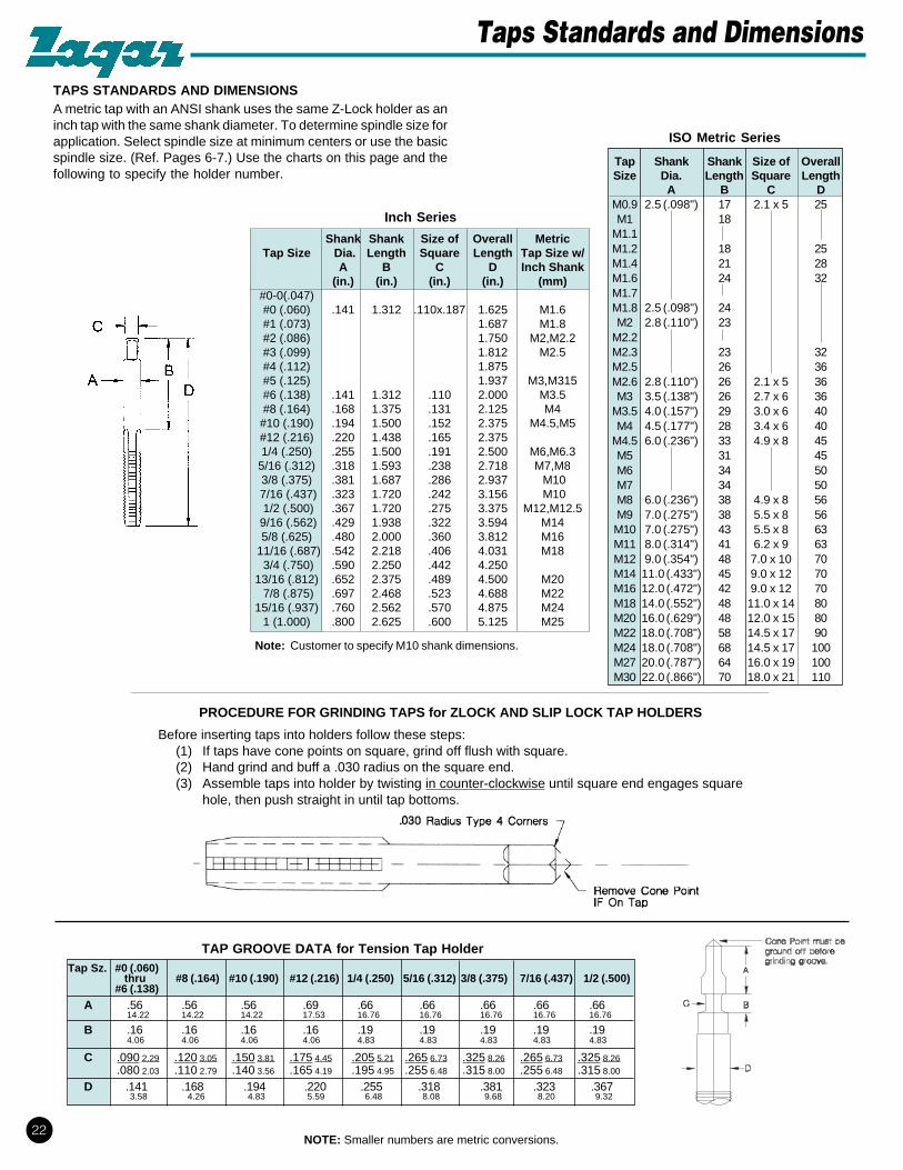
TAPS STANDARDS AND DIMENSIONSA metric tap with an ANSI shank uses the same Z-Lock holder as aninch tap with the same shank diameter. To determine spindle size forapplication. Select spindle size at minimum centers or use the basicspindle size. (Ref. Pages 6-7.) Use the charts on this page and thefollowing to specify the holder number.

Tap Shank Shank Size of OverallSize Dia. Length Square Length

A B C DM0.9 2.5 (.098") 17 2.1 x 5 25M1 18

M1.1M1.2 18 25M1.4 21 28M1.6 24 32M1.7M1.8 2.5 (.098") 24M2 2.8 (.110") 23

M2.2M2.3 23 32M2.5 26 36M2.6 2.8 (.110") 26 2.1 x 5 36M3 3.5 (.138") 26 2.7 x 6 36

M3.5 4.0 (.157") 29 3.0 x 6 40M4 4.5 (.177") 28 3.4 x 6 40

M4.5 6.0 (.236") 33 4.9 x 8 45M5 31 45M6 34 50M7 34 50M8 6.0 (.236") 38 4.9 x 8 56M9 7.0 (.275") 38 5.5 x 8 56M10 7.0 (.275") 43 5.5 x 8 63M11 8.0 (.314") 41 6.2 x 9 63M12 9.0 (.354") 48 7.0 x 10 70M14 11.0 (.433") 45 9.0 x 12 70M16 12.0 (.472") 42 9.0 x 12 70M18 14.0 (.552") 48 11.0 x 14 80M20 16.0 (.629") 48 12.0 x 15 80M22 18.0 (.708") 58 14.5 x 17 90M24 18.0 (.708") 68 14.5 x 17 100M27 20.0 (.787") 64 16.0 x 19 100M30 22.0 (.866") 70 18.0 x 21 110

ISO Metric Series

Note: Customer to specify M10 shank dimensions.

Inch Series

PROCEDURE FOR GRINDING TAPS for ZLOCK AND SLIP LOCK TAP HOLDERS

Before inserting taps into holders follow these steps:(1) If taps have cone points on square, grind off flush with square.(2) Hand grind and buff a .030 radius on the square end.(3) Assemble taps into holder by twisting in counter-clockwise until square end engages square

hole, then push straight in until tap bottoms.

TAP GROOVE DATA for Tension Tap HolderTap Sz. #0 (.060)

thru #8 (.164) #10 (.190) #12 (.216) 1/4 (.250) 5/16 (.312) 3/8 (.375) 7/16 (.437) 1/2 (.500)#6 (.138)

A .56 .56 .56 .69 .66 .66 .66 .66 .6614.22 14.22 14.22 17.53 16.76 16.76 16.76 16.76 16.76

B .16 .16 .16 .16 .19 .19 .19 .19 .194.06 4.06 4.06 4.06 4.83 4.83 4.83 4.83 4.83

C .090 2.29 .120 3.05 .150 3.81 .175 4.45 .205 5.21 .265 6.73 .325 8.26 .265 6.73 .325 8.26.080 2.03 .110 2.79 .140 3.56 .165 4.19 .195 4.95 .255 6.48 .315 8.00 .255 6.48 .315 8.00

D .141 .168 .194 .220 .255 .318 .381 .323 .3673.58 4.26 4.83 5.59 6.48 8.08 9.68 8.20 9.32

Shank Shank Size of Overall MetricTap Size Dia. Length Square Length Tap Size w/

A B C D Inch Shank(in.) (in.) (in.) (in.) (mm)

#0-0(.047)#0 (.060) .141 1.312 .110x.187 1.625 M1.6#1 (.073) 1.687 M1.8#2 (.086) 1.750 M2,M2.2#3 (.099) 1.812 M2.5#4 (.112) 1.875#5 (.125) 1.937 M3,M315#6 (.138) .141 1.312 .110 2.000 M3.5#8 (.164) .168 1.375 .131 2.125 M4#10 (.190) .194 1.500 .152 2.375 M4.5,M5#12 (.216) .220 1.438 .165 2.3751/4 (.250) .255 1.500 .191 2.500 M6,M6.3

5/16 (.312) .318 1.593 .238 2.718 M7,M83/8 (.375) .381 1.687 .286 2.937 M10

7/16 (.437) .323 1.720 .242 3.156 M10 1/2 (.500) .367 1.720 .275 3.375 M12,M12.5

9/16 (.562) .429 1.938 .322 3.594 M145/8 (.625) .480 2.000 .360 3.812 M16

11/16 (.687) .542 2.218 .406 4.031 M18 3/4 (.750) .590 2.250 .442 4.250

13/16 (.812) .652 2.375 .489 4.500 M20 7/8 (.875) .697 2.468 .523 4.688 M22

15/16 (.937) .760 2.562 .570 4.875 M241 (1.000) .800 2.625 .600 5.125 M25

22NOTE: Smaller numbers are metric conversions.

Taps Standards and Dimensions

INCORPORATED24000 Lakeland BoulevardCleveland, Ohio 44132 U.S.A.216/731-0500 FAX 216/731-8591

MULTIPLESPINDLE

HeadDataQuestionnaire

Information given (by customer) on this Questionnaire is assumed correct and final for Head(s)being ordered. • Any changes after order is placed may result in additional charges. • Anyomission on this questionnaire will cause a delay in the delivery of head(s).

55

Part Information:

1. Part No. _____________________________________

2. Part Print Enclosed____________________________

3. Sample Part Submitted o Yes o No

4. Type of Material

o Aluminum o Plastico Brass o Stainless Steelo Cast Iron o Steelo Magnesium o _________________

Drill Head Layout:1. Use the appropriate Head Layout Form on Pages 2

or 3 to show your hole pattern in relation to headcenterlines and guide rods. We accept yourAutocad layouts on disk.

2. On Page 4 give make, model and completespecifications of drill press as applicable.

Customer Information

Date ________________________________ Zagar Sales Rep. ___________________________________________________

Name ________________________________________ Title _____________________________________________________

Company ______________________________________________________________________________________________

Street _________________________________________________________________________________________________

City _________________________________________ State _________________________ Zip ________________________

Phone________________________________________ FAX _____________________________________________________

Drilling Information:

1. Operating R.P.M. (Zagar heads are 1:1 ratio) _____2. Operation(s) Required

o Chamfer o Reamo Drill and Chamfer o Spotfaceo Countersink o Tapo Drill o _________________

3. How many holes? ________

4. Do you have a fixture for part? o Yes o NoIf not, see fixture information on Page 3.

Note: Multiple-Spindle Heads require guide rod tie in oftooling. The Zagar standard distance is shown inZagar's Multiple Spindle Drill Head Catalog, Page 10.

5. o Verticle spindles–pointing down.

o Horizontal spindles

o Inverted spindles–pointing up

o _______________________________

HeadOperatingPosition

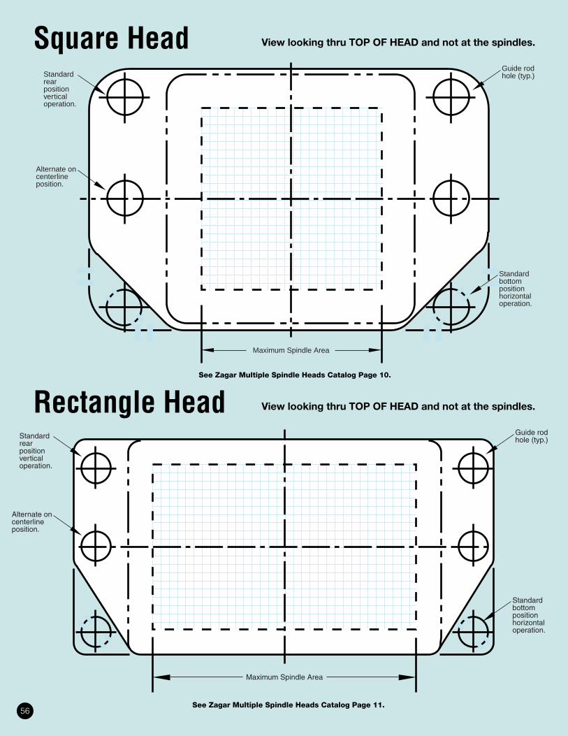
Square Head View looking thru TOP OF HEAD and not at the spindles.

Rectangle Head View looking thru TOP OF HEAD and not at the spindles.

See Zagar Multiple Spindle Heads Catalog Page 10.

See Zagar Multiple Spindle Heads Catalog Page 11.56

Standardrearpositionvertical operation.

Alternate oncenterlineposition.

Guide rodhole (typ.)

Maximum Spindle Area

Standardbottompositionhorizontaloperation.

Diagonal Head View looking thru TOP OF HEAD and not at the spindles.

Typical Available FixturesSee Multiple Spindle Heads Technical Specifications Catalog, Page 26 for complete, partially complete andblank fixture assemblies and components. Autocad disk available to show these assemblies on your layouts.

Complete Partially Complete Blank Assemblies

See Zagar Multiple Spindle Heads Catalog Page 10.

57

Quill & Spindle Specs.

INCORPORATED24000 Lakeland BoulevardCleveland, Ohio 44132 U.S.A.216/731-0500 FAX 216/731-8591

Drill Press Specs.

Make _________________________________________________

Model ________________________________________________

Comments ____________________________________________

______________________________________________________

______________________________________________________

58

LENGTH OF CHORDST = length of chordD = diameter of circleC = constant for each No. of divisions N

To obtain length of chord T, multiply the diameter of D by the constant C.

T = DC

N C N C N C N C3 .86603 28 .11196 53 .05924 78 .040274 .70711 29 .10812 54 .05814 79 .039765 .58779 30 .10453 55 .05709 80 .039266 .50000 31 .10117 56 .05607 81 .038787 .43388 32 .09802 57 .05509 82 .03830

8 .38268 33 .09506 58 .05414 83 .037849 .34202 34 .09227 59 .05322 84 .03739

10 .30902 35 .08964 60 .05234 85 .0369511 .28173 36 .08716 61 .05148 86 .0365212 .25882 37 .08481 62 .05065 87 .03610

13 .23932 38 .08258 63 .04985 88 .0356914 .22252 39 .08047 64 .04907 89 .0352915 .20791 40 .07846 65 .04831 90 .0349016 .19509 41 .07655 66 .04758 91 .0345217 .18375 42 .07473 67 .04687 92 .03414

18 .17365 43 .07300 68 .04618 93 .0337719 .16459 44 .07134 69 .04551 94 .0334120 .15643 45 .06976 70 .04486 95 .0330621 .14904 46 .06824 71 .04423 96 .0327222 .14231 47 .06679 72 .04362 97 .03238

23 .13617 48 .06540 73 .04302 98 .0320524 .13053 49 .06407 74 .04244 99 .0317325 .12533 50 .06279 75 .04188 100 .0314126 .12054 51 .06156 76 .04132 101 .03110

27 .11609 52 .06038 77 .04079 102 .03080

42

Bolt Circle Center Distance Formula

++( )

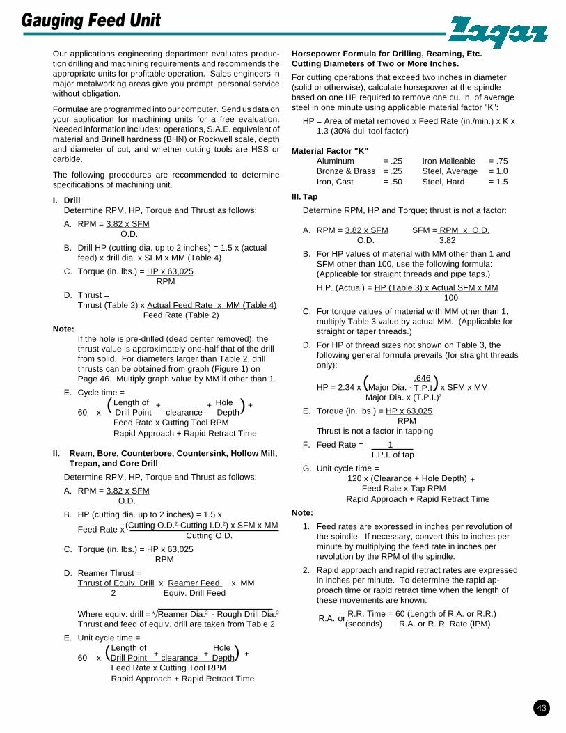
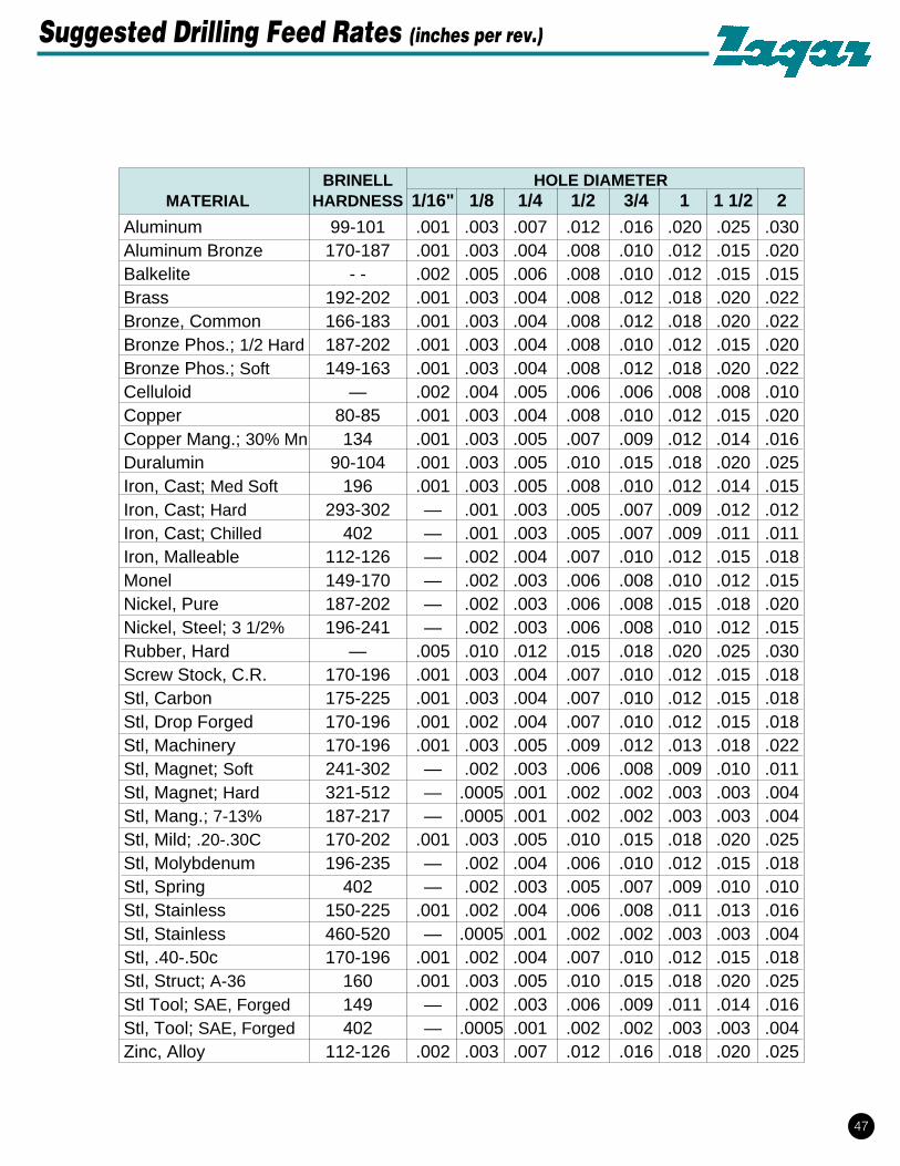
Horsepower Formula for Drilling, Reaming, Etc.Cutting Diameters of Two or More Inches.

For cutting operations that exceed two inches in diameter(solid or otherwise), calculate horsepower at the spindlebased on one HP required to remove one cu. in. of averagesteel in one minute using applicable material factor "K":

HP = Area of metal removed x Feed Rate (in./min.) x K x1.3 (30% dull tool factor)

Material Factor "K"Aluminum = .25 Iron Malleable = .75Bronze & Brass = .25 Steel, Average = 1.0Iron, Cast = .50 Steel, Hard = 1.5

III. Tap

Determine RPM, HP and Torque; thrust is not a factor:

A. RPM = 3.82 x SFM SFM = RPM x O.D. O.D. 3.82

B. For HP values of material with MM other than 1 andSFM other than 100, use the following formula:(Applicable for straight threads and pipe taps.)

H.P. (Actual) = HP (Table 3) x Actual SFM x MM 100

C. For torque values of material with MM other than 1,multiply Table 3 value by actual MM. (Applicable forstraight or taper threads.)

D. For HP of thread sizes not shown on Table 3, thefollowing general formula prevails (for straight threadsonly):

HP = 2.34 x Major Dia. - x SFM x MM Major Dia. x (T.P.I.)2

E. Torque (in. lbs.) = HP x 63,025 RPM

Thrust is not a factor in tapping

F. Feed Rate = 1 T.P.I. of tap

G. Unit cycle time = 120 x (Clearance + Hole Depth) Feed Rate x Tap RPM

Rapid Approach + Rapid Retract Time

Note:

1. Feed rates are expressed in inches per revolution ofthe spindle. If necessary, convert this to inches perminute by multiplying the feed rate in inches perrevolution by the RPM of the spindle.

2. Rapid approach and rapid retract rates are expressedin inches per minute. To determine the rapid ap-proach time or rapid retract time when the length ofthese movements are known:

R.R. Time = 60 (Length of R.A. or R.R.) (seconds) R.A. or R. R. Rate (IPM)

Feed Rate x

Our applications engineering department evaluates produc-tion drilling and machining requirements and recommends theappropriate units for profitable operation. Sales engineers inmajor metalworking areas give you prompt, personal servicewithout obligation.

Formulae are programmed into our computer. Send us data onyour application for machining units for a free evaluation.Needed information includes: operations, S.A.E. equivalent ofmaterial and Brinell hardness (BHN) or Rockwell scale, depthand diameter of cut, and whether cutting tools are HSS orcarbide.

The following procedures are recommended to determinespecifications of machining unit.

I. DrillDetermine RPM, HP, Torque and Thrust as follows:

A. RPM = 3.82 x SFM O.D.

B. Drill HP (cutting dia. up to 2 inches) = 1.5 x (actualfeed) x drill dia. x SFM x MM (Table 4)

C. Torque (in. lbs.) = HP x 63,025 RPM

D. Thrust =Thrust (Table 2) x Actual Feed Rate x MM (Table 4)

Feed Rate (Table 2)

Note:If the hole is pre-drilled (dead center removed), thethrust value is approximately one-half that of the drillfrom solid. For diameters larger than Table 2, drillthrusts can be obtained from graph (Figure 1) onPage 46. Multiply graph value by MM if other than 1.

E. Cycle time = Length of Hole60 x Drill Point clearance Depth Feed Rate x Cutting Tool RPM Rapid Approach + Rapid Retract Time

II. Ream, Bore, Counterbore, Countersink, Hollow Mill,Trepan, and Core Drill

Determine RPM, HP, Torque and Thrust as follows:

A. RPM = 3.82 x SFM O.D.

B. HP (cutting dia. up to 2 inches) = 1.5 x (Cutting O.D.2-Cutting I.D.2) x SFM x MM

Cutting O.D.

C. Torque (in. lbs.) = HP x 63,025 RPM

D. Reamer Thrust =Thrust of Equiv. Drill x Reamer Feed x MM 2 Equiv. Drill Feed

Where equiv. drill = Reamer Dia.2 - Rough Drill Dia.2

Thrust and feed of equiv. drill are taken from Table 2.

E. Unit cycle time = Length of Hole60 x Drill Point clearance Depth Feed Rate x Cutting Tool RPM Rapid Approach + Rapid Retract Time

+

+

R.A. or

43

+ +( ) +

( .646T.P.I.)

Gauging Feed Unit

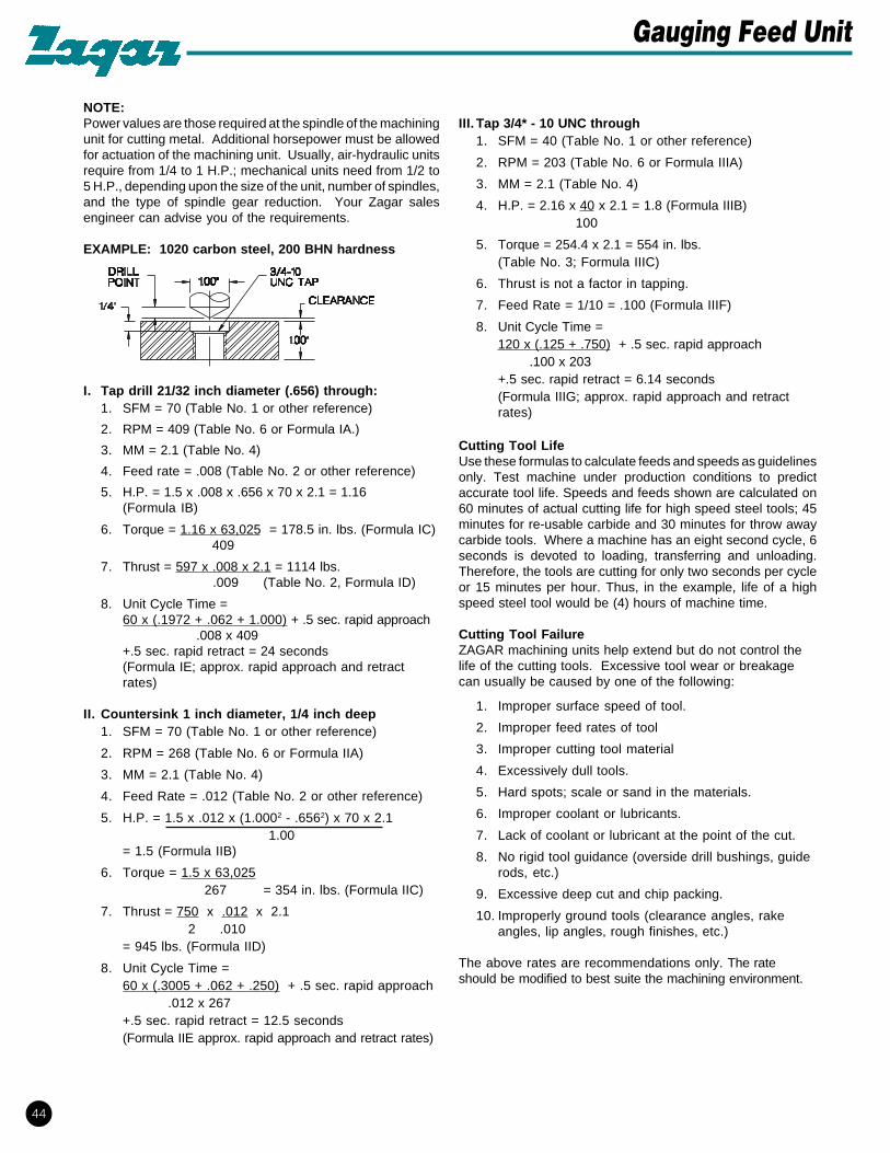
NOTE:Power values are those required at the spindle of the machiningunit for cutting metal. Additional horsepower must be allowedfor actuation of the machining unit. Usually, air-hydraulic unitsrequire from 1/4 to 1 H.P.; mechanical units need from 1/2 to5 H.P., depending upon the size of the unit, number of spindles,and the type of spindle gear reduction. Your Zagar salesengineer can advise you of the requirements.

EXAMPLE: 1020 carbon steel, 200 BHN hardness

I. Tap drill 21/32 inch diameter (.656) through:1. SFM = 70 (Table No. 1 or other reference)

2. RPM = 409 (Table No. 6 or Formula IA.)

3. MM = 2.1 (Table No. 4)

4. Feed rate = .008 (Table No. 2 or other reference)

5. H.P. = 1.5 x .008 x .656 x 70 x 2.1 = 1.16(Formula IB)

6. Torque = 1.16 x 63,025 = 178.5 in. lbs. (Formula IC) 409

7. Thrust = 597 x .008 x 2.1 = 1114 lbs. .009 (Table No. 2, Formula ID)

8. Unit Cycle Time =60 x (.1972 + .062 + 1.000) + .5 sec. rapid approach

.008 x 409+.5 sec. rapid retract = 24 seconds(Formula IE; approx. rapid approach and retractrates)

II. Countersink 1 inch diameter, 1/4 inch deep1. SFM = 70 (Table No. 1 or other reference)

2. RPM = 268 (Table No. 6 or Formula IIA)

3. MM = 2.1 (Table No. 4)

4. Feed Rate = .012 (Table No. 2 or other reference)

5. H.P. = 1.5 x .012 x (1.0002 - .6562) x 70 x 2.1 1.00

= 1.5 (Formula IIB)

6. Torque = 1.5 x 63,025 267 = 354 in. lbs. (Formula IIC)

7. Thrust = 750 x .012 x 2.12 .010

= 945 lbs. (Formula IID)

8. Unit Cycle Time =60 x (.3005 + .062 + .250) + .5 sec. rapid approach

.012 x 267+.5 sec. rapid retract = 12.5 seconds(Formula IIE approx. rapid approach and retract rates)

III. Tap 3/4* - 10 UNC through1. SFM = 40 (Table No. 1 or other reference)

2. RPM = 203 (Table No. 6 or Formula IIIA)

3. MM = 2.1 (Table No. 4)

4. H.P. = 2.16 x 40 x 2.1 = 1.8 (Formula IIIB) 100

5. Torque = 254.4 x 2.1 = 554 in. lbs.(Table No. 3; Formula IIIC)

6. Thrust is not a factor in tapping.

7. Feed Rate = 1/10 = .100 (Formula IIIF)

8. Unit Cycle Time =120 x (.125 + .750) + .5 sec. rapid approach .100 x 203+.5 sec. rapid retract = 6.14 seconds(Formula IIIG; approx. rapid approach and retractrates)

Cutting Tool LifeUse these formulas to calculate feeds and speeds as guidelinesonly. Test machine under production conditions to predictaccurate tool life. Speeds and feeds shown are calculated on60 minutes of actual cutting life for high speed steel tools; 45minutes for re-usable carbide and 30 minutes for throw awaycarbide tools. Where a machine has an eight second cycle, 6seconds is devoted to loading, transferring and unloading.Therefore, the tools are cutting for only two seconds per cycleor 15 minutes per hour. Thus, in the example, life of a highspeed steel tool would be (4) hours of machine time.

Cutting Tool FailureZAGAR machining units help extend but do not control thelife of the cutting tools. Excessive tool wear or breakagecan usually be caused by one of the following:

1. Improper surface speed of tool.

2. Improper feed rates of tool

3. Improper cutting tool material

4. Excessively dull tools.

5. Hard spots; scale or sand in the materials.

6. Improper coolant or lubricants.

7. Lack of coolant or lubricant at the point of the cut.

8. No rigid tool guidance (overside drill bushings, guiderods, etc.)

9. Excessive deep cut and chip packing.

10. Improperly ground tools (clearance angles, rakeangles, lip angles, rough finishes, etc.)

The above rates are recommendations only. The rateshould be modified to best suite the machining environment.

44

Gauging Feed Unit

With carbide drills decrease feed rate 10% and double drill RPM and HP.

TAPS - S.F.M.MATERIAL BRINELL DRILLS THREADS PER INCH

(BHN) S.F.M. 3-7 1/2 8-15 16-24 25 UPAluminum 99-101 200-250 50 100 150 200Aluminum Bronze 170-187 60 12 25 45 60Bakelite — 80 50 100 150 200Brass 192-202 200-250 50 100 150 200Bronze, Common 166-183 200-250 40 80 100 150Bronze, Phos.; 1/2 Hard 187-202 175-180 25 40 50 80Bronze, Phos.; Soft 149-163 200-250 40 80 100 150Celluloid — 100 50 100 150 200Copper 80-85 70 40 80 100 150Copper, Mang.; 30% Min. 134 15 — — — —Duralumin 90-104 200 50 100 150 200Everdur 179-207 60 20 30 40 50Iron, Cast; Soft 126 140-150 30 60 90 140Iron, Cast; Med. Soft 196 80-110 25 40 50 80Iron, Cast; Hard 293-302 45-50 10 20 30 40Iron, Cast; Chilled 402 15 5 5 10 10Iron Malleable 112-126 85-90 20 30 40 50Monel 149-170 50 8 10 15 20Nickel, Pure 187-202 75 25 40 50 80Nickel Steel; 3 1/2% 196-241 60 8 10 15 20Rubber, Hard — 100 50 100 150 200

DRILL THRUST AND HORSEPOWERMM of one (cast iron)

DRILL DRILL FEED* HP@ THRUST TORQUEDIA. POINT IN./REV. 100 S.F.M. LBS. IN-LBS.1/32 .009 .0008 .004 10 0.021/16 .019 .0015 .014 31 0.143/32 .028 .0020 .028 45 0.41/8 .037 .0025 .047 66 0.95/32 .047 .0035 .082 110 2.13/16 .056 .0040 .113 131 3.47/32 .066 .0045 .148 168 5.31/4 .075 .0050 .188 194 7.79/32 .084 .0050 .211 210 9.85/16 .094 .0050 .235 227 12.

11/32 .103 .0055 .284 261 16.3/8 .113 .0060 .338 296 20.

13/32 .122 .0065 .396 333 26.7/16 .131 .0070 .460 372 33.

15/32 .141 .0075 .526 413 40.1/2 .150 .0080 .600 474 49.

17/32 .160 .0080 .637 503 56.9/16 .169 .0080 .675 533 62.

19/32 .178 .0085 .757 569 74.5/8 .188 .0090 .844 587 87.

21/32 .197 .0090 .885 597 96.11/16 .206 .0090 .928 627 105.23/32 .216 .0095 1.025 685 121.3/4 .225 .0100 1.125 729 139.

25/32 .235 .0100 1.175 750 151.13/16 .244 .0100 1.218 771 163.27/32 .253 .0105 1.335 822 185.7/8 .263 .0110 1.45 875 209.

29/32 .272 .0115 1.56 925 234.15/16 .282 .0120 1.68 983 261.31/32 .291 .0125 1.81 1097 291.

1 .300 .013 1.96 1164 322.1 1/16 .319 .013 2.13 1180 364.1 1/8 .338 .014 2.37 1266 439.1 3/16 .357 .014 2.50 1360 490.1 1/4 .376 .015 2.64 1440 581.1 5/16 .394 .015 2.70 1490 641.1 3/8 .413 .015 3.04 1540 704.1 7/16 .432 .015 3.23 1590 769.1 1/2 .451 .015 3.37 1640 837.1 9/16 .469 .016 3.78 1730 969.1 5/8 .488 .016 3.94 1820 1048

1 11/16 .507 .016 4.07 1870 1131.1 3/4 .526 .016 4.35 1915 1216.

1 13/16 .544 .016 4.50 2005 1304.1 7/8 .563 .017 4.75 2115 1483

1 15/16 .582 .017 4.95 2165 1584.2 .601 .017 5.12 2211 1688.

Table No.1

Table No. 2

TAPS-S.F.M.MATERIAL BRINELL DRILLS THREADS PER INCH

(BHN) S.F.M. 3-7 1/2 8-15 16-24 25 UPScrew Stock; C.R. 170-196 110 20 30 40 50Steel, Carbon 175-225 70 30 40 50 50Steel, Drop Forged 170-196 60 12 25 45 60Steel, Machinery 170-196 110 35 50 60 85Steel, Magnet; Soft 241-302 35-40 20 40 50 75Steel, Magnet; Hard 321-512 15 5 10 15 25Steel, Mang.; 7-13% 187-217 15 15 20 25 30Steel, Mild; .20-.30C 170-202 110-120 40 55 70 90Steel, Molybdenum 196-235 55 20 30 35 45Steel, Spring 402 20 10 10 15 15Steel, Stainless 150-225 50 8 10 15 20Steel, Stainless 460-520 20 8 10 15 20Steel .40-.50C 170-196 80 20 30 40 50Steel, Structural; A-36 160 110 40 55 70 90Steel, Tool; S.A.E. and Forging 149 75 25 35 45 55Steel, Tool; S.A.E. and Forging 241 50 15 15 25 25Steel, Tool; S.A.E. and Forging 402 15 8 10 15 20Zinc, Alloy 112-126 200-250 50 100 150 200

NOTE: 1) HSS reaming tools should be at approximately 2/3 of Drill RPM.2) Carbide tools should be at approximately double above values.

Table No. 3 - Tapping, MM of one (cast iron)TAP

SIZE SERIES DRILL RPM @ HP @ TORQUE75% 100 S.F.M. 100 S.F.M. IN-LBS.

6-32 UNC .1077 2775 .19 4.46-40 UNF .1138 2775 .12 2.98-32 UNC .1337 2335 .2 5.48-36 UNF .137 2335 .16 4.310-24 UNC .149 2016 .35 10.910-32 UNF .1597 2016 .2 6.412-24 UNC .175 1773 .36 12.612-28 UNF .1813 1773 .27 9.51/4-20 UNC .2115 1532 .51 211/4-28 UNF .2153 1532 .27 115/16-18 UNC .2589 1226 .64 335/16-24 UNF .2715 1226 .37 19.13/8-16 UNC .3144 1021 .82 503/8-24 UNF .334 1021 .38 23.37/16-14 UNC .3681 875.5 1.1 777/16-20 UNF .3890 875.5 .54 391/2-13 UNC .4251 766 1.25 102.61/2-20 UNF .4515 766 .55 459/16-12 UNC .4817 681 1.5 1369/16-18 UNF .5089 681 .68 62.55/8-11 UNC .5365 613 1.75 1805/8-18 UNF .5714 613 .68 703/4-10 UNC .6562 511 2.1 2643/4-16 UNF .6894 511 .87 1077/8-9 UNC .7667 438 2.7 3827/8-14 UNF .8056 438 1.1 1631"-8 UNC .8781 383 3.4 5531-12 UNF .9192 383 1.5 253

1 1/8-7 UNC .9857 340 4.4 8121 1/8-12 UNF 1.0442 340 1.6 2861 1/4-7 UNC 1.1107 306 4.4 9101 1/4-12 UNF 1.1692 306 1.6 3201 3/8-6 UNC 1.2125 279 6 13561 3/8-12 UNF 1.2942 279 1.6 3531 1/2-6 UNC 1.3375 255 6 14891 1/2-12 UNF 1.4192 255 1.6 3871 3/4-5 UNC 1.5552 219 8.7 24962"-4 1/2 UNC 1.7836 191 10.7 3530

2 1/4-4 1/2 UNC 2.0336 170 10.8 40052 1/2-4 UNC 2.2565 153 13.7 56282 3/4-4 UNC 2.5065 139 13.8 6230

3"-4 UNC 2.7565 127 13.8 68313 1/4-4 UNC 3.0065 118 13.9 74333 1/2-4 UNC 3.2565 109 13.95 80353 3/4-4 UNC 3.5065 102 14 8636

4"-4 UNC 3.7565 96 14 9238

PIPE TAPS (TAPER)The following H.P. and Torque specs are based on tapered

hole. If hole is straight, multiply by (3) three.1/8-27 NPT R 948 .54 36

1/4-18 NPT 7/16 706 1.17 1033/8-18 NPT 37/64 565 1.69 1331/2-14 NPT 23/32 455 2.00 2773/4-14 NPT 59/64 364 2.06 356

1-11 1/2 NPT 1 5/32 291 3.07 6631 1/4-11 1/2 NPT 1 1/2 231 3.48 9501 1/2-11 1/2 NPT 1 47/64 201 4.08 1280

2-11 1/2 NPT 2 7/32 161 5.31 2080

45

Suggested Cutting Speeds with HSS Cutting Tools

MATERIAL MULTIPLIERS (MM)

RELATIVE MACHINABILITY BASED ON CAST IRON = 1

MATERIAL BHN MM MATERIAL BHN MMAluminum .38 Free Cutting (1111-1213) 140 1.10Brass .60 Alloy Steel(1330-8642) 175 1.50Bronze .60 190 1.60Cast Iron 1.00 200 1.70Copper .72 203 1.80Magnesium .80 205 1.90Malleable Iron 1.20 210 2.00Stainless Steel 2.50 215 2.10Titanium 2.25 220 2.20Zinc .60 230 2.30Carbon Steel 240 2.40

(1008-1095) 90 1.60 250 2.50110 1.70 330 3.30140 1.80 390 3.90170 1.90 470 4.60190 2.00 Structural Steel (A-36) 160 1.50200 2.10250 2.20

SPINDLE RPM FOR VARIOUS CUTTING DIAMETERS WITH GIVEN SURFACE SPEED. (For higher speeds, multiply 150' values by new 5FM/150.)

SFM 10' 20' 30' 40' 50' 60' 70' 80' 90' 100' 110' 120' 130' 140' 150'

DIAMETER

INCHES REVOLUTIONS PER MINUTE

1/16 611 1222 1833 2445 3056 3667 4278 4889 5500 — — — — — —

1/8 306 611 917 1222 1528 1833 2139 2445 2750 3056 3361 3667 3973 4278 4584

3/16 204 407 611 815 1019 1222 1426 1630 1833 2037 2241 2445 2648 2852 3056

1/4 153 306 458 611 764 917 1070 1222 1375 1528 1681 1833 1986 2139 2292

5/16 122 244 367 489 611 733 856 978 1100 1222 1345 1467 1589 1711 1833

3/8 102 204 306 407 509 611 713 815 917 1019 1120 1222 1324 1426 1528

7/16 87 175 262 349 437 524 611 698 786 873 960 1048 1135 1222 1310

1/2 76 153 229 306 382 458 535 611 688 764 840 917 993 1070 1146

5/8 61 122 183 244 306 367 428 489 550 611 672 733 794 856 917

3/4 51 102 153 203 255 306 357 407 458 509 560 611 662 713 764

7/8 44 87 131 175 218 262 306 349 393 436 480 524 568 611 655

1 38 76 115 153 191 229 267 306 344 382 420 458 497 535 573

1 1/8 34 68 102 136 170 204 238 272 306 340 373 407 441 475 509

1 1/4 31 61 92 122 153 183 214 244 275 306 336 367 397 428 458

1 3/8 28 56 83 111 139 167 194 222 250 278 306 333 361 389 417

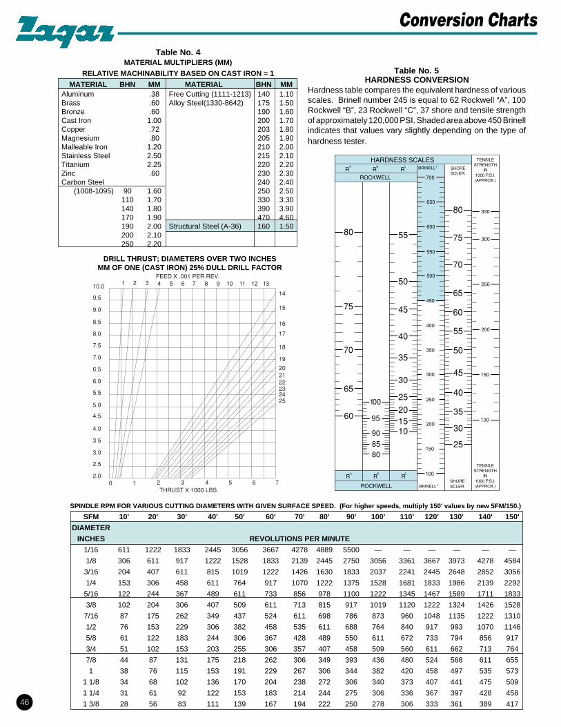
DRILL THRUST; DIAMETERS OVER TWO INCHESMM OF ONE (CAST IRON) 25% DULL DRILL FACTOR

HARDNESS CONVERSIONHardness table compares the equivalent hardness of variousscales. Brinell number 245 is equal to 62 Rockwell “A”, 100Rockwell “B”, 23 Rockwell “C”, 37 shore and tensile strengthof approximately 120,000 PSI. Shaded area above 450 Brinellindicates that values vary slightly depending on the type ofhardness tester.

Table No. 4

Table No. 5

46

Conversion Charts

BRINELL HOLE DIAMETERMATERIAL HARDNESS 1/16" 1/8 1/4 1/2 3/4 1 1 1/2 2

Aluminum 99-101 .001 .003 .007 .012 .016 .020 .025 .030Aluminum Bronze 170-187 .001 .003 .004 .008 .010 .012 .015 .020Balkelite - - .002 .005 .006 .008 .010 .012 .015 .015Brass 192-202 .001 .003 .004 .008 .012 .018 .020 .022Bronze, Common 166-183 .001 .003 .004 .008 .012 .018 .020 .022Bronze Phos.; 1/2 Hard 187-202 .001 .003 .004 .008 .010 .012 .015 .020Bronze Phos.; Soft 149-163 .001 .003 .004 .008 .012 .018 .020 .022Celluloid — .002 .004 .005 .006 .006 .008 .008 .010Copper 80-85 .001 .003 .004 .008 .010 .012 .015 .020Copper Mang.; 30% Mn 134 .001 .003 .005 .007 .009 .012 .014 .016Duralumin 90-104 .001 .003 .005 .010 .015 .018 .020 .025Iron, Cast; Med Soft 196 .001 .003 .005 .008 .010 .012 .014 .015Iron, Cast; Hard 293-302 — .001 .003 .005 .007 .009 .012 .012Iron, Cast; Chilled 402 — .001 .003 .005 .007 .009 .011 .011Iron, Malleable 112-126 — .002 .004 .007 .010 .012 .015 .018Monel 149-170 — .002 .003 .006 .008 .010 .012 .015Nickel, Pure 187-202 — .002 .003 .006 .008 .015 .018 .020Nickel, Steel; 3 1/2% 196-241 — .002 .003 .006 .008 .010 .012 .015Rubber, Hard — .005 .010 .012 .015 .018 .020 .025 .030Screw Stock, C.R. 170-196 .001 .003 .004 .007 .010 .012 .015 .018Stl, Carbon 175-225 .001 .003 .004 .007 .010 .012 .015 .018Stl, Drop Forged 170-196 .001 .002 .004 .007 .010 .012 .015 .018Stl, Machinery 170-196 .001 .003 .005 .009 .012 .013 .018 .022Stl, Magnet; Soft 241-302 — .002 .003 .006 .008 .009 .010 .011Stl, Magnet; Hard 321-512 — .0005 .001 .002 .002 .003 .003 .004Stl, Mang.; 7-13% 187-217 — .0005 .001 .002 .002 .003 .003 .004Stl, Mild; .20-.30C 170-202 .001 .003 .005 .010 .015 .018 .020 .025Stl, Molybdenum 196-235 — .002 .004 .006 .010 .012 .015 .018Stl, Spring 402 — .002 .003 .005 .007 .009 .010 .010Stl, Stainless 150-225 .001 .002 .004 .006 .008 .011 .013 .016Stl, Stainless 460-520 — .0005 .001 .002 .002 .003 .003 .004Stl, .40-.50c 170-196 .001 .002 .004 .007 .010 .012 .015 .018Stl, Struct; A-36 160 .001 .003 .005 .010 .015 .018 .020 .025Stl Tool; SAE, Forged 149 — .002 .003 .006 .009 .011 .014 .016Stl, Tool; SAE, Forged 402 — .0005 .001 .002 .002 .003 .003 .004Zinc, Alloy 112-126 .002 .003 .007 .012 .016 .018 .020 .025

47

Suggested Drilling Feed Rates (inches per rev.)

TAP DRILL SIZES FOR CUT AND FORMED THREADSTAP DRILL SIZE TAP TAP DRILL SIZE

Cut Thread Formed Thread SIZE Cut Thread Formed Thread29 .1360 25 .1495 7/16-14 U .3680 13/32 .40629 .1360 24 .1520 7/16-20 25/64 .3906 10.5 mm .413423 .1540 11/64 .1719 1/2-13 27/64 .4219 * .46620 .1610 16 .1770 1/2-20 29/64 .4531 * .47815 .1800 5 mm .1968 9/16-12 31/64 .4844 * .52513 .1850 8 .1990 9/16-18 33/64 .5156 * .53813/64 .2031 1 .2280 5/8-11 35/64 .5469 * .5847/32 .2187 A .2340 5/8-18 37/64 .5781 * .600G .2610 7.3 mm .2874 11/16-11 39/64 .6094 * .646J .2770 M .2950 11/16-16 5/8 .6250 * .660O .3160 S .3480 3/4-10 21/32 .6562 45/64 .7031R .3390 T .358 3/4-16 11/16 .6875 * .722

NOTE: Cut thread tap drill sizes are for 2 B threads. Formed thread tap drill sizes are for approximately 65% thread. *Special drill sizes

Inch Decimal Wire mm

1/16 .0625.0630 1.60.0635 52.0650 1.65.0669 1.70.0670 51.0689 1.75.0700 50.0709 1.80.0728 1.85.0730 49.0748 1.90.0760 48.0768 1.95

5/64 .0781.0785 47.0787 2.00.0807 2.05.0810 46.0820 45.0827 2.10.0846 2.15.0860 44.0866 2.20.0886 2.25.0890 43.0906 2.30.0925 2.35.0935 42

3/32 .0938.0945 2.40.0960 41.0965 2.45.0980 40.0981 2.50.0995 39.1015 38.1024 2.60.1040 37.1063 2.70.1065 36.1083 2.75

7/64 .1094.1100 35.1102 2.80.1110 34.1130 33.1142 2.90.1160 32.1181 3.00.1200 31.1220 3.10

1/8 .1250.1260 3.20.1280 3.25.1285 30.1299 3.30

Inch Decimal Wire mm

.1339 3.40

.1360 29

.1378 3.50

.1405 289/64 .1406

.1417 3.60

.1440 27

.1457 3.70

.1470 26

.1476 3.75

.1495 25

.1496 3.80

.1520 24

.1535 3.90

.1540 235/32 .1562

.1570 22

.1575 4.00

.1590 21

.1610 20

.1614 4.10

.1654 4.20

.1660 19

.1673 4.25

.1693 4.30

.1695 1811/64 .1719

.1730 17

.1732 4.40

.1770 16

.1772 4.50

.1800 15

.1811 4.60

.1820 14

.1850 13

.1850 4.70

.1870 4.753/16 .1875

.1890 4.80

.1890 12

.1910 11

.1929 4.90

.1935 10

.1960 9

.1969 5.00

.1990 8

.2008 5.10

.2010 713/64 .2031

.2040 6

.2047 5.20

.2055 5

.2067 5.25

.2087 5.30

.2090 4

.2126 5.40

.2130 3

Inch Decimal Wire mm

.2165 5.507/32 .2188

.2205 5.60

.2210 2

.2244 5.70

.2264 5.75

.2280 1

.2283 5.80

.2323 5.90

.2340 A15/64 .2344

.2362 6.00

.2380 B

.2402 6.10

.2420 C

.2441 6.20

.2460 D

.2461 6.25

.2480 6.301/4 .2500 E

.2520 6.40

.2559 6.50

.2570 F

.2598 6.60

.2610 G

.2638 6.7017/64 .2656

.2657 6.75

.2660 H

.2677 6.80

.2717 6.90

.2720 I

.2756 7.00

.2770 J

.2795 7.10

.2810 K9/32 .2812

.2835 7.20

.2854 7.25

.2874 7.30

.2900 L

.2913 7.40

.2950 M

.2953 7.5019/64 .2969

.2992 7.60

.3020 N

.3031 7.70

.3051 7.75

.3071 7.80

.3110 7.905/16 .3125

.3150 8.00

.3160 O

.3189 8.10

.3228 8.20

.3230 P

Inch Decimal Wire mm

.3248 8.25

.3268 8.3021/64 .3281

.3307 8.40

.3320 Q

.3346 8.50

.3386 8.60

.3390 R

.3425 8.7011/32 .3438

.3445 8.75

.3465 8.80

.3480 S

.3504 8.90

.3543 9.00

.3580 T

.3583 9.1023/64 .3594

.3622 9.20

.3642 9.25

.3661 9.30

.3680 U

.3701 9.40

.3740 9.503/8 .3750

.3770 V

.3780 9.60

.3819 9.70

.3839 9.75

.3858 9.80

.3860 W

.3898 9.9025/64 .3906

.3937 10.0

.3970 X

.4040 Y13/32 .4062

.4130 Z

.4134 10.527/64 .4219

.4331 11.07/16 .4375

.4528 11.529/64 .453115/32 .4688

.4724 12.031/64 .4844

.4921 12.51/2 .5000

.5118 13.033/64 .515617/32 .5312

.5315 13.535/64 .5469

.5512 14.09/16 .5625

.5709 14.5

Inch Decimal Wire mm

37/64 .5781.5906 15.0

19/32 .593839/64 .6094

.6102 15.55/8 .6250

.6299 16.041/64 .6406

.6496 16.521/32 .6562

.6693 17.043/64 .671911/16 .6875

.6890 17.545/64 .7031

.7087 18.023/32 .7188

.7283 18.547/64 .7344

.7480 19.03/4 .750049/64 .7656

.7677 19.525/32 .7812

.7874 20.051/64 .7969

.8071 20.513/16 .8125

.8268 21.053/64 .828127/32 .8438

.8465 21.555/64 .8594

.8661 22.07/8 .8750

.8858 22.557/64 .8906

.9055 23.029/32 .906259/64 .8906

.9252 23.515/16 .9375

.9445 2461/64 .9531

.9646 24.531/32 .9688

.9843 25.063/64 .98441" 1.000

TAP TAP DRILL SIZE TAPSIZE Cut Thread Formed Thread SIZE0-80 3/64 .0469 54 .0545 8-321-64 53 .0595 1.65 mm .065 8-361-72 53 .0595 1.7 mm .0669 10-242-56 50 .0700 5/64 .0781 10-322-64 50 .0700 2 mm .0787 12-243-48 46 .0810 43 .089 12-283-56 45 .0820 2.3 mm .0906 1/4-204-40 43 .0890 39 .0995 1/4-284-48 3/32 .0938 2.6 mm .1024 5/16-185-40 38 .1015 33 .113 5/16-245-44 37 .1040 2.9 mm .1142 3/8-166-32 34 .1110 1/8 .125 3/8-246-40 32 .1160 3.2 mm .1260

Inch Decimal Wire mm

1/64 .0156.0157 0.40.0160 78.0165 0.42.0173 0.44.0177 0.45.0180 77.0181 0.46.0189 0.48.0197 0.50.0200 76.0210 75.0217 0.55.0225 74.0236 0.60.0240 73.0250 72.0256 0.65.0260 71.0276 0.70.0280 70.0292 69.0295 0.75.0310 68

1/32 .0312.0315 0.80.0320 67.0330 66.0335 0.85.0350 65.0354 0.90.0360 64.0370 63.0374 0.95.0380 62.0390 61.0394 1.00.0400 60.0410 59.0413 1.05.0420 58.0430 57.0433 1.10.0453 1.15.0465 56

3/64 .0469.0472 1.20.0492 1.25.0512 1.30.0520 55.0531 1.35.0550 54.0551 1.40.0571 1.45.0591 1.50.0595 53.0610 1.55

59

Drill Sizes in Decimal Equivalents

PITCHTap Size Decimal (threads MM Per Threads

Equivalent per in.) Thread per mm

.90 mm .03541.0 mm .0393 101.60 .25 4.0001.1 mm .0433 101.60 .25 4.0001.2 mm .0472 101.60 .25 4.0001.4 mm .0551 84.66 .30 3.333

#0 .0600 801/16" .0625 64

1.7 mm .0669 72.56 .35 2.8571.8 mm .0708 72.56 .35 2.857

#1 .0730 64#1 .0730 72

2.0 mm .0787 63.50 .40 2.500#2 .0860 64

2.3 mm .0905 63.50 .40 2.5003/32" .0625 64#3 .0990 48#3 .0990 56

2.6 mm .1023 56.43 .45 2.2221/8" .1250 40#4 .1120 32#4 .1120 36#4 .1120 40#4 .1120 48

3.0 mm .1181 50.80 .50 2.000#5 .1250 40#5 .1250 44

3.5 mm .1378 42.33 .60 1.666#6 .1380 32#6 .1380 40

5/32" .1562 325/32" .1562 36

4.0 mm .1574 36.28 .70 1.428#8 .1640 32#8 .1640 36#8 .1640 40

4.5 mm .1771 33.86 .75 1.3333/16" .1870 243/16" .1870 32#10 .1900 24#10 .1900 32#10 .1900 30

5.0 mm .1980 31.75 .80 1.250#12 .2160 24#12 .2160 28#12 .2160 32

7/32" .2188 247/32" .2188 32

6.0 mm .2326 25.4 1.00 1.00#14 .2420 20#14 .2420 241/4" .2500 20

PITCHTap Size Decimal Threads (mm per Threads

Equivalent Per In. thread) per mm

1/4" .2500 241/4" .2500 281/4" .2500 32

7.0 mm .2755 25.4 1.00 1.005/16" .3120 185/16" .3120 24

8.0 mm .3149 20.32 1.25 .8009.0 mm .3543 20.32 1.25 .800

3/8" .3750 163/8" .3750 24

10.0 mm .3937 16.93 1.50 .66611.0 mm .4330 16.93 1.50 .666

7/16" .4370 147/16" .4370 20

12.0 mm .4724 14.51 1.75 .5711/2" .5000 131/2" .5000 20

14.0 mm .5510 12.70 2.00 .5005/8" .6250 115/8" .6250 18

16.0 mm .6299 12.70 2.00 .50011/16" .6870 1111/16" .6870 16

18.0 mm .7086 10.16 2.50 .4003/4" .7500 103/4" .7500 16

20.0 mm .7870 10.16 2.50 .40013/16" .8120 1213/16" .8120 1613/16" .8120 2013/16" .8120 2813/16" .8120 32

22.0 mm .8666 10.16 2.50 .4007/8" .8750 97/8" .8750 14

15/16" .9370 1215/16" .9370 1615/16" .9370 2015/16" .9370 2815/16" .9370 32

24.0 mm .9448 8.46 3.00 .3331.00 “ 1.0000 81.00 “ 1.0000 121.00 “ 1.0000 14

27.0 mm 1.0629 8.46 3.00 .3331-1/8" 1.1250 71-1/8" 1.1250 12

30.0 mm 1.1810 7.25 3.50 .2851-1/4" 1.2500 71-1/4" 1.2500 12

33.0 mm 1.2999 7.25 3.50 .285

48

Tap Holder Reference Chart


Recommended