78
® For the Zebra 400™ and 600™ Printers S S Customer order # 44885L Manufacturer part # 44885LB Rev. 2 User’s Guide
| Date post: | 31-Aug-2014 |
| Category: |
Documents |
| Upload: | robert-stwuart |
| View: | 42 times |
| Download: | 0 times |
®
For the Zebra 400™ and 600™ PrintersS S
Customer order # 44885L
Manufacturer part # 44885LB Rev. 2
User’s
Guide
1
Proprietary StatementThis manual contains proprietary information of Zebra Technologies Corporation. It isintended solely for the information and use of parties operating and maintaining theequipment described herein. Such proprietary information may not be used, reproduced, ordisclosed to any other parties for any other purpose without the expressed writtenpermission of Zebra Technologies Corporation.
Product ImprovementsContinuous improvement of products is a policy of Zebra Technologies Corporation. Allspecifications and signs are subject to change without notice.
FCC Compliance StatementNOTE: This equipment has been tested and found to comply with the limits for a Class Bdigital device, pursuant to Part 15 of the FCC Rules. These limits are designed to providereasonable protection against harmful interference in a residential installation. Thisequipment generates, uses, and can radiate radio frequency energy and, if not installed andused in accordance with the instructions, may cause harmful interference to radiocommunications. However, there is no guarantee that the interference will not occur in aparticular installation. If this equipment does cause harmful interference to radio ortelevision reception, which can be determined by turning the equipment off and on, theuser is encouraged to try to correct the interference by one or more of the followingmeasures:
n Reorient or relocate the receiving antenna.
n Increase the separation between the equipment and the receiver.
n Connect the equipment into an outlet on a circuit different than that to which the receiver isconnected.
n Consult the dealer or an experienced Radio/TV technician for help.
NOTE: This unit was tested with shielded cables on the peripheral devices. Shieldedcables must be used with the unit to insure compliance.
The user is cautioned that any changes or modifications not expressly approved by ZebraTechnologies Corporation could void the users authority to operate the equipment.
Canadian DOC Compliance StatementThis digital apparatus does not exceed the Class A limits for radio noise emissions fromdigital apparatus as set out in the radio interference regulations of the CanadianDepartment of Communications.
Liability DisclaimerZebra Technologies Corporation takes steps to assure that its published Engineeringspecifications and Manuals are correct; however, errors do occur. Zebra TechnologiesCorporation reserves the right to correct any such errors and disclaims liability resultingtherefrom.
No Liability for Consequential DamageIn no event shall Zebra Technologies corporation or anyone else involved in the creation,production, or delivery of the accompanying product (including hardware and software) beliable for any damages whatsoever (including, without limitation, damages for loss ofbusiness profits, business interruption, loss of business information, or other pecuniaryloss) arising out of the use of or the results of use of or inability to use such product, evenif Zebra Technologies Corporation has been advised of the possibility of such damages.Because some states do not allow the exclusion or limitation of liability for consequentialor incidental damages, the above limitation may not apply to you.
CopyrightsThis copyrighted manual and the label printer described herein are owned by ZebraTechnologies Corporation. All rights are reserved. Unauthorized reproduction of thismanual or the software in the label printer may result in imprisonment of up to one yearand fines of up to $10,000 (17 U.S.C.506). Copyright violators may be subject to civilliability.
All products and brand names are trademarks of their respective companies. All rightsreserved.
© 1998 Zebra Technologies Corporation
2

I have determined that the Zebra printers identified as the
Stripe Series400 and 600S S
manufactured by:
Zebra Technologies Corporation333 Corporate Woods Parkway
Vernon Hills, Illinois 60061-3109 U.S.A.
have been shown to comply with the applicable technical standards of the FCC
for Home, Office, Commercial, and Industrial use
if no unauthorized change is made in the equipment,and if the equipment is properly maintained and operated.
3

4

Contents
Introduction
Unpacking . . . . . . . . . . . . . . . . . . . . . . . . . . . . . . . . . . 1
Reporting Damage. . . . . . . . . . . . . . . . . . . . . . . . . . . . . . 1
Site Requirements . . . . . . . . . . . . . . . . . . . . . . . . . . . . . . 2
Introduction to Printers . . . . . . . . . . . . . . . . . . . . . . . . . . . 2
Tear-Off Mode . . . . . . . . . . . . . . . . . . . . . . . . . . . . . . 2
Peel-Off Mode . . . . . . . . . . . . . . . . . . . . . . . . . . . . . . 3
Cutter Mode . . . . . . . . . . . . . . . . . . . . . . . . . . . . . . . . 3
Printer Overview . . . . . . . . . . . . . . . . . . . . . . . . . . . . . . 4
Getting Ready to Print
AC Power Cable. . . . . . . . . . . . . . . . . . . . . . . . . . . . . . . 5
Loading the Media . . . . . . . . . . . . . . . . . . . . . . . . . . . . . 7
Tear-Off Mode . . . . . . . . . . . . . . . . . . . . . . . . . . . . . . 7
Roll Media . . . . . . . . . . . . . . . . . . . . . . . . . . . . . . . 7
Fanfold Media . . . . . . . . . . . . . . . . . . . . . . . . . . . . . 8
Peel-Off Mode . . . . . . . . . . . . . . . . . . . . . . . . . . . . . . 9
Removing the Label Backing Material . . . . . . . . . . . . . . . . 10
Cutter Mode . . . . . . . . . . . . . . . . . . . . . . . . . . . . . . . 11
Loading the Ribbon . . . . . . . . . . . . . . . . . . . . . . . . . . . . 12
Ribbon Supply Spindle: Normal Position . . . . . . . . . . . . . . . . 12
Ribbon Supply Spindle: Low-Tension Position . . . . . . . . . . . . . 12
Ribbon Loading Instructions . . . . . . . . . . . . . . . . . . . . . . 13
Ribbon Removal . . . . . . . . . . . . . . . . . . . . . . . . . . . . . . 14
Adjusting the Media Sensor . . . . . . . . . . . . . . . . . . . . . . . . 15
Non-Continuous Media . . . . . . . . . . . . . . . . . . . . . . . . . 15
Continuous Media . . . . . . . . . . . . . . . . . . . . . . . . . . . . 15
Auto Calibration . . . . . . . . . . . . . . . . . . . . . . . . . . . . . . 16
Operator Controls . . . . . . . . . . . . . . . . . . . . . . . . . . . . . 16
Front Panel Buttons . . . . . . . . . . . . . . . . . . . . . . . . . . . 16
Front Panel LEDs . . . . . . . . . . . . . . . . . . . . . . . . . . . . 17
AC Power ON/OFF Switch . . . . . . . . . . . . . . . . . . . . . . . . 18
S400 & S600 User’s Guide i
5
Printing a Test Label . . . . . . . . . . . . . . . . . . . . . . . . . . . . 18
Connecting the Printer and Computer . . . . . . . . . . . . . . . . . . . 18
RS-232 Interface Requirements . . . . . . . . . . . . . . . . . . . . . 18
Parallel Interface Requirements . . . . . . . . . . . . . . . . . . . . . 19
Serial and Parallel Cabling Requirements . . . . . . . . . . . . . . . . 19
Communicating with the Printer . . . . . . . . . . . . . . . . . . . . . . 19
Via the Parallel Port . . . . . . . . . . . . . . . . . . . . . . . . . . . 19
Via the Serial Port . . . . . . . . . . . . . . . . . . . . . . . . . . . . 19
Defaulting the Printer . . . . . . . . . . . . . . . . . . . . . . . . . . 19
Autobaud. . . . . . . . . . . . . . . . . . . . . . . . . . . . . . . . . 20
^SC Command. . . . . . . . . . . . . . . . . . . . . . . . . . . . . . 20
Setting Up the Software . . . . . . . . . . . . . . . . . . . . . . . . . . 20
Routine Care and Adjustments
Cleaning . . . . . . . . . . . . . . . . . . . . . . . . . . . . . . . . . . 21
Cleaning the Exterior . . . . . . . . . . . . . . . . . . . . . . . . . . 23
Cleaning the Interior . . . . . . . . . . . . . . . . . . . . . . . . . . . 23
Cleaning the Printhead and Platen Roller . . . . . . . . . . . . . . . . 23
Cleaning the Cutter Module . . . . . . . . . . . . . . . . . . . . . . . 24
Lubrication . . . . . . . . . . . . . . . . . . . . . . . . . . . . . . . . . 30
AC Power Fuse Replacement . . . . . . . . . . . . . . . . . . . . . . . 30
Mechanical Adjustments . . . . . . . . . . . . . . . . . . . . . . . . . . 31
Print Quality Adjustments . . . . . . . . . . . . . . . . . . . . . . . . 31
Toggle Pressure Adjustment. . . . . . . . . . . . . . . . . . . . . . . 31
Media Rest Position Adjustment . . . . . . . . . . . . . . . . . . . . 33
Top of the Label Position Adjustment. . . . . . . . . . . . . . . . . . 33
Media Sensor Position Adjustment . . . . . . . . . . . . . . . . . . . 33
Ribbon Supply Spindle Adjustment . . . . . . . . . . . . . . . . . . . 33
Backing Rewind Power Roller Adjustment . . . . . . . . . . . . . . . 34
Troubleshooting
Troubleshooting Table . . . . . . . . . . . . . . . . . . . . . . . . . . . 37
Printer Status Sensors . . . . . . . . . . . . . . . . . . . . . . . . . . . 43
Manual Calibration. . . . . . . . . . . . . . . . . . . . . . . . . . . . . 45
Resetting Printer Parameters . . . . . . . . . . . . . . . . . . . . . . . . 46
ii S400 & S600 User’s Guide
6
Resetting Factory Defaults . . . . . . . . . . . . . . . . . . . . . . . 46
Resetting Communications Parameters . . . . . . . . . . . . . . . . . 46
Resetting Ribbon Parameters . . . . . . . . . . . . . . . . . . . . . . 46
Printer Diagnostics . . . . . . . . . . . . . . . . . . . . . . . . . . . . . 47
Power-On Self Test . . . . . . . . . . . . . . . . . . . . . . . . . . . 47
Additional Printer Self Tests . . . . . . . . . . . . . . . . . . . . . . 47
CANCEL Key Self Test. . . . . . . . . . . . . . . . . . . . . . . . 48
PAUSE Key Self Test . . . . . . . . . . . . . . . . . . . . . . . . . 49
FEED Key Self Test. . . . . . . . . . . . . . . . . . . . . . . . . . 50
MODE Key Self Test . . . . . . . . . . . . . . . . . . . . . . . . . 51
Specifications
General Specifications . . . . . . . . . . . . . . . . . . . . . . . . . . . 53
Printing Specifications . . . . . . . . . . . . . . . . . . . . . . . . . . . 54
Ribbon Specifications . . . . . . . . . . . . . . . . . . . . . . . . . . . 54
Media Specifications . . . . . . . . . . . . . . . . . . . . . . . . . . . . 55
Media Handling . . . . . . . . . . . . . . . . . . . . . . . . . . . . . . 55
Options . . . . . . . . . . . . . . . . . . . . . . . . . . . . . . . . . . . 56
Zebra Programming Language (ZPL II®) . . . . . . . . . . . . . . . . . 56
Bar Codes . . . . . . . . . . . . . . . . . . . . . . . . . . . . . . . . . 57
Standard Printer Fonts . . . . . . . . . . . . . . . . . . . . . . . . . . . 57
Optional Printer Fonts . . . . . . . . . . . . . . . . . . . . . . . . . . . 57
Appendix
RS-232 Connector Technical Information . . . . . . . . . . . . . . . . . 59
Interconnecting to DTE Devices . . . . . . . . . . . . . . . . . . . . 59
Interconnecting to DCE Devices . . . . . . . . . . . . . . . . . . . . 59
Parallel Interface Technical Information. . . . . . . . . . . . . . . . . . 61
Storage and Reshipping . . . . . . . . . . . . . . . . . . . . . . . . . . 62
Glossary
Index
S400 & S600 User’s Guide iii
7

iv S400 & S600 User’s Guide
8
Introduction
Congratulations! You have just purchased a high-quality thermal labelprinter manufactured by the industry leader in quality, service, and value.For over 25 years, Zebra Technologies Corporation has provided customerswith the highest caliber of products and support.
n This user's guide provides all the information you will need to operatethe printer on a daily basis.
n ZPL II® is Zebra Technologies Corporation’s Zebra ProgrammingLanguage II label design language. ZPL II lets you create a wide varietyof labels from the simple to the very complex, including text, bar codes,and graphics. To create and print label formats, refer to the ZPL IIProgramming Guide (part #46469L). If one was not ordered with yourprinter, simply call your distributor or Zebra Technologies Corporation.
n In addition, label preparation software is available. Contact yourdistributor or Zebra Technologies Corporation for further information.Or, visit our web site for a free demo copy.
n The S400/S600 Maintenance Manual (part #44895L) contains all theinformation you will need to maintain your printer. To order, contactyour distributor or Zebra Technologies Corporation.
Unpacking
Save the carton and all packing materials in case reshipping is required.
Inspect the printer for possible shipping damage.
n Check all exterior surfaces for damage.
n Raise the media access cover (refer to Figure 4) and inspect the mediacompartment for damage.
Reporting Damage
If you discover shipping damage:
n Immediately notify and file a damage report with the shipping company.Zebra Technologies Corporation is not responsible for any damageincurred during shipment of the printer and will not cover the repair ofthis damage under its warranty policy.
n Keep the carton and all packing material for inspection.
n Notify your authorized Zebra distributor.
For storage and reshipping information, refer to the Appendix.
S400 & S600 User’s Guide 1
9
Site Requirements
CAUTION: To insure that the printer has proper ventilation and cooling,
do not place any padding or cushioning material under the unit, because
this restricts air flow.
This printer may be installed on any solid, level surface of sufficient sizeand strength to accommodate the physical dimensions and weight of theunit. The area enclosure in which the printer will operate must meet theenvironmental conditions specified. Electrical power must be available and inclose proximity to the printer.
Since this printer was designed and is fabricated as an industrial-type unit, itwill function satisfactorily in areas such as warehouses, factory floors, andoffice environments that conform to specified environmental and electricalconditions.
Introduction to Printers
The first thing you want to do is identify your printer. This makes certaintasks -- such as media loading -- much easier to do!
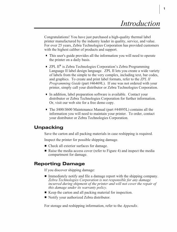
If your printerlooks like this(Figure 1), it isset up forTear-Off mode.Tear-Off allowsyou to tear awayeach label, or astrip of labels,after it isprinted.
To load media,refer to“Loading theMedia --Tear-Off Mode”in Getting Readyto Print.
2 S400 & S600 User’s Guide
Figure 1
10
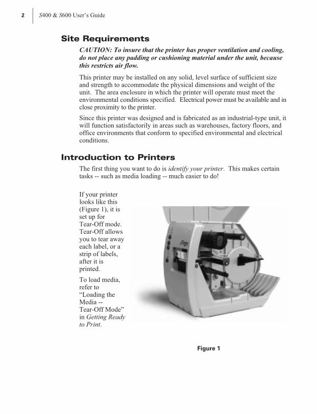
This printer(Figure 2)operates inPeel-Off mode.In Peel-Off,backing materialis peeled awayfrom the label asit is printed.After this label isremoved from theprinter, the nextone is printed.
To load media,refer to “Loadingthe Media --Peel-Off Mode”in Getting Readyto Print.
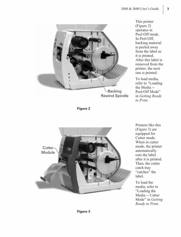
Printers like this(Figure 3) areequipped forCutter mode.When in cuttermode, the printerautomaticallycuts the labelafter it is printed.Then, the cuttercatch tray“catches” thelabel.
To load themedia, refer to“Loading theMedia -- CutterMode” in GettingReady to Print.
S400 & S600 User’s Guide 3
Backing
Rewind Spindle
Figure 2
Cutter
Module
Figure 3
11
4 S400 & S600 User’s Guide
12
13
14
15
1
2
3
4
5
6
7
8
9
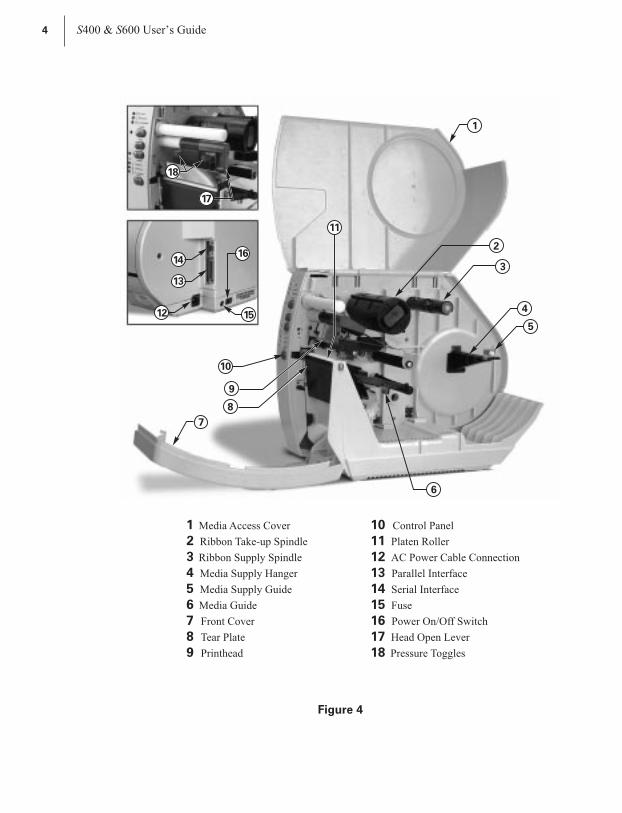
Media Access Cover
Ribbon Take-up Spindle
Ribbon Supply Spindle
Media Supply Hanger
Media Supply Guide
Media Guide
Front Cover
Tear Plate
Printhead
10
11
12
13
14
15
16
17
18
Control Panel
Platen Roller
AC Power Cable Connection
Parallel Interface
Serial Interface
Fuse
Power On/Off Switch
Head Open Lever
Pressure Toggles
1
2
3
4
5
6
10
9
8
7
16
11
17
18
Figure 4
12
Getting Ready to Print
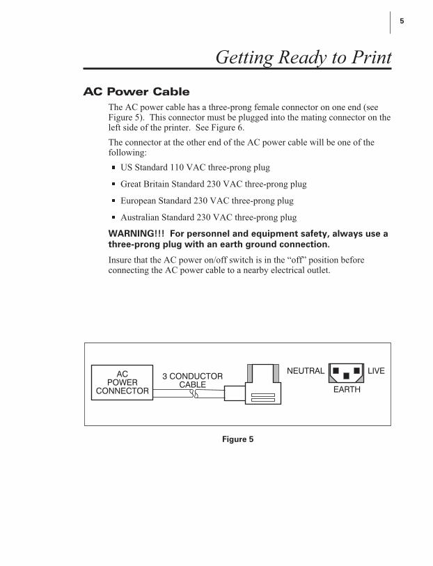
AC Power Cable
The AC power cable has a three-prong female connector on one end (seeFigure 5). This connector must be plugged into the mating connector on theleft side of the printer. See Figure 6.
The connector at the other end of the AC power cable will be one of thefollowing:
n US Standard 110 VAC three-prong plug
n Great Britain Standard 230 VAC three-prong plug
n European Standard 230 VAC three-prong plug
n Australian Standard 230 VAC three-prong plug
WARNING!!! For personnel and equipment safety, always use athree-prong plug with an earth ground connection.
Insure that the AC power on/off switch is in the “off” position beforeconnecting the AC power cable to a nearby electrical outlet.
S400 & S600 User’s Guide 5
AC
POWER
CONNECTOR
3 CONDUCTOR
CABLE
NEUTRAL LIVE
EARTH
Figure 5
13

6 S400 & S600 User’s Guide
AC Power Cable
Connection
Power
On/Off
Switch
Fuse
RS-232
(Serial)
Interface
Parallel
Interface
Figure 6
14
Loading the Media
Media widths and thicknesses vary between applications. To maintain printquality from one application to another, refer to “Print QualityAdjustments” in Routine Care and Adjustments.
NOTE: Zebra recommends using media that is outside wound (you can seethe labels on the outside of the roll).
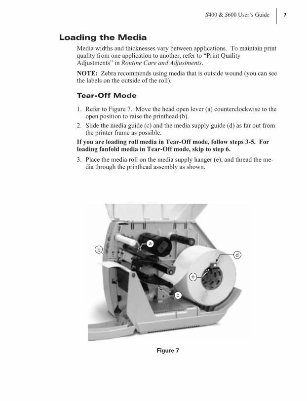
Tear-Off Mode
1. Refer to Figure 7. Move the head open lever (a) counterclockwise to theopen position to raise the printhead (b).
2. Slide the media guide (c) and the media supply guide (d) as far out fromthe printer frame as possible.
If you are loading roll media in Tear-Off mode, follow steps 3-5. Forloading fanfold media in Tear-Off mode, skip to step 6.
3. Place the media roll on the media supply hanger (e), and thread the me-dia through the printhead assembly as shown.
S400 & S600 User’s Guide 7
d
c
e
ab
Figure 7
15

4. Adjust the media supply guide and the media guide against the outeredge of the media. These guides must not cause pressure or excessivedrag on the media.
5. Close the head open lever, and see “Adjusting the Media Sensor” later inthis chapter to adjust the media sensor position.
For loading fanfold media:
6. Refer to Figure 8. Make sure the fanfold media feeds through either thebottom (e) or rear (f) access slot.
NOTE: When utilizing the bottom access slot, be sure to thread media overthe media supply hanger.
7. Thread the media through the printhead as shown in Figure 8.
8. Adjust the media supply guide and the media guide against the outeredge of the media. These guides must not cause pressure or excessivedrag on the media.
9. Close the head open lever, and see “Adjusting the Media Sensor” later inthis chapter to adjust the media sensor position.
8 S400 & S600 User’s Guide
f
e
Figure 8
16

Peel-Off Mode (Optional)
Refer to Figure 9 and follow the procedure below.
1. Slide the media supply guide (a), media guide (b), and the outer edgeguides on both the platen guide rod (c) and the lower guide rod (d) as farout from the printer frame as possible.
2. Open the head open lever (e) to raise the printhead (f).
3. Remove the hold down hook (g).
4. Thread the media through the printhead as shown in Figure 9.
5. From the front of the printer, pull the media through the printhead untilapproximately 24" of media extends out from the printer. Remove thelabels from the backing of the 24" of media that extends from the frontof the printer.
6. Align the inside edge of the media with the edge guide mark (h) near theleft side of the tear-off/peel-off plate, then close the head open lever.(See Figure 25 for a detailed illustration.)
7. Thread the label backing behind the lower label available sensor (i),through the slot under the rewind power roller (j), and below the lowerguide rod (k) to the backing rewind spindle (l). Then, wind the backingmaterial around the backing rewind spindle three or four times in acounterclockwise direction. To insure proper winding, press the edge ofthe backing material against the round plate at the far end of the spindle.
S400 & S600 User’s Guide 9
a
b
k
l
j
c
i
h
e
f
d
g
Figure 9
17

8. To hold the media against the spindle, place the hold down hook overthe backing and insert both ends into the small slots in the round plate atthe far end of the spindle. Again, rotate the backing rewind spindlecounterclockwise to remove any slack in the backing material.
9. Adjust all of the guides:
n Push the media supply guide inward until it is just touching the outerside of the media supply roll, then lock the guide in place with itslocking screw. The guide must not cause pressure or excessive drag onthe media supply roll.
n Adjust the outer edge guides on both the lower guide rod and the platenguide rod until they just touch the outer edge of the media and backingwithout causing the material to buckle.
n Adjust the media guide until it just touches the outer edge of the mediawithout causing the material to buckle.
10.See “Adjusting the Media Sensor” later in this chapter to adjust the me-dia sensor.
NOTE: In the Peel-Off mode, proper media tracking is critical. Refer tothe “Backing Rewind Power Roller Adjustment” in Routine Care andAdjustments to make sure that the media tracks properly through theprinter.
Removing the Label Backing Material (Peel-Off Option Re-
quired)
When the amount of backing wound on the backing rewind spindle reachesfull capacity, the backing rewind spindle full sensor activates, thepaper/ribbon light flashes, and printing pauses.
To remove the backing material, follow these steps (you don’t need topower off the printer for this procedure):
1. Unwind about 24" of backing from the backing rewind spindle and cut itoff at the spindle.
2. Pull out the hold down hook and slide the backing material off of thespindle and discard.
3. Feed the new starting edge of the backing through the mechanism andattach it to the backing rewind spindle as described in the loading proce-dure.
NOTE: While holding the media in position against the tear-off/peel-offplate, open and close the printhead without disturbing the media position.The printer is now ready to print more labels.
10 S400 & S600 User’s Guide
18
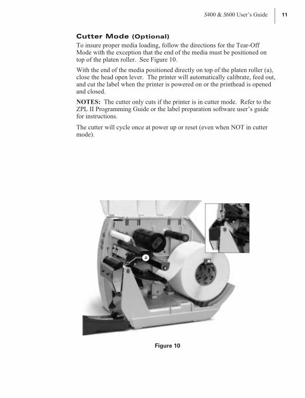
Cutter Mode (Optional)
To insure proper media loading, follow the directions for the Tear-OffMode with the exception that the end of the media must be positioned ontop of the platen roller. See Figure 10.
With the end of the media positioned directly on top of the platen roller (a),close the head open lever. The printer will automatically calibrate, feed out,and cut the label when the printer is powered on or the printhead is openedand closed.
NOTES: The cutter only cuts if the printer is in cutter mode. Refer to theZPL II Programming Guide or the label preparation software user’s guidefor instructions.
The cutter will cycle once at power up or reset (even when NOT in cuttermode).
S400 & S600 User’s Guide 11
a
Figure 10
19

Loading the Ribbon
Before you load the ribbon, make sure the ribbon supply spindle is adjustedproperly.
Ribbon Supply Spindle: Normal Position
In the normal position, the “dual-tension” ribbon supply spindle providesthe desired amount of ribbon back tension for different ribbon widths.
To place the spindle in the normal position, firmly pull the spindle end cap(a) until it clicks into place, as shown in Figure 11.
Ribbon Supply Spindle: Low-Tension Position
Low-tension position is used in limited applications to provide lower ribbonback tension. Low-tension position is only recommended when normaltension hampers the ribbon movement (for example, you will see scuffingor image breakup on the label).
To put the spindle in the low-tension position, firmly push the spindle endcap (a) until it clicks into place, as shown in Figure 11.
12 S400 & S600 User’s Guide
a
a
b
Normal Position
Low-Tension Position
Figure 11
20
Ribbon Loading Instructions
NOTES:
n Zebra recommends the use of ribbon that is wider than the media. Thesmooth backing of the ribbon protects the printhead from wear andpremature failure due to excessive abrasion. (For the direct thermalprint method, ribbon is not used and should not be loaded in theprinter.)
n Zebra recommends the use of ribbon that is outside wound (the ink sideis on the outside of the roll).
To load ribbon, see Figure 12 and follow the procedure below.
1. Adjust the ribbon supply spindle position for normal or low tension.
2. Align the blades (b) on the two sections of the spindle as shown inFigure 11. (You do not need to do this if your ribbon width is 2.4"[60 mm] or less.)
3. Place the ribbon roll on the ribbon supply spindle (a). Make sure the rollis pushed in to the stop at the end of the spindle.
4. Open the printhead by moving the head open lever (b) counterclockwiseto the open position.
5. Thread the ribbon as shown. Wind the ribbon onto the ribbon takeupspindle (c) for several turns in a clockwise direction until wrinkles andcreases disappear.
6. Close the printhead by moving the lever clockwise to the closed posi-tion.
S400 & S600 User’s Guide 13
21

Ribbon Removal
Refer to Figure 12.
When it’s time to change the ribbon, cut the ribbon where it is stretchedbetween the upper ribbon guide arm and the takeup spindle. To removeribbon from the takeup spindle, press the release button (d) and slide theribbon off the spindle.
14 S400 & S600 User’s Guide
ad
c
b
Figure 12
22
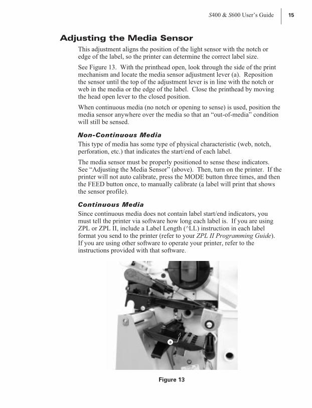
Adjusting the Media Sensor
This adjustment aligns the position of the light sensor with the notch oredge of the label, so the printer can determine the correct label size.
See Figure 13. With the printhead open, look through the side of the printmechanism and locate the media sensor adjustment lever (a). Repositionthe sensor until the top of the adjustment lever is in line with the notch orweb in the media or the edge of the label. Close the printhead by movingthe head open lever to the closed position.
When continuous media (no notch or opening to sense) is used, position themedia sensor anywhere over the media so that an “out-of-media” conditionwill still be sensed.
Non-Continuous Media
This type of media has some type of physical characteristic (web, notch,perforation, etc.) that indicates the start/end of each label.
The media sensor must be properly positioned to sense these indicators.See “Adjusting the Media Sensor” (above). Then, turn on the printer. If theprinter will not auto calibrate, press the MODE button three times, and thenthe FEED button once, to manually calibrate (a label will print that showsthe sensor profile).
Continuous Media
Since continuous media does not contain label start/end indicators, youmust tell the printer via software how long each label is. If you are usingZPL or ZPL II, include a Label Length (^LL) instruction in each labelformat you send to the printer (refer to your ZPL II Programming Guide).If you are using other software to operate your printer, refer to theinstructions provided with that software.
S400 & S600 User’s Guide 15
a
Figure 13
23

Auto Calibration
This procedure occurs whenever the printer is turned on or the printhead isopened and closed. During this procedure, the printer automaticallydetermines the media type, label length, media and ribbon sensor settings,and printing method (direct thermal or thermal transfer). This procedure isset at the factory but may be changed via ZPL II command.
NOTE: If the printer fails to auto calibrate when you are using pre-printedlabels or pre-printed label backing, or if the printer will not auto calibrate,see “Manual Calibration” in Troubleshooting.
1. Load the media and ribbon (if used).
2. Turn on the printer power.
3. Two or three blank labels will feed, completing auto calibration.
Operator Controls
Front Panel Buttons
Refer to Figure 14.
PAUSE Button
n Starts and stops the printing process.
n The first time the button is pressed, any partially printed label iscompleted; then, the printing process is stopped.
n If the printer is idle when the button is pressed, no new print requests areprinted until PAUSE is pressed again.
FEED Button (also referred to as the UP button)
n Forces the printer to feed one blank label.
n If the button is pressed when the printer is idle or paused, a blank labelimmediately feeds.
n When the button is pressed while the printer is printing, one blank labelfeeds after the completion of the current batch of labels.
n Once the blank label has been fed, pressing the button again will feed asecond label.
n When in the configuration mode, functions as the UP button.
CANCEL Button (also referred to as the DOWN button)
n This button only functions when the printer is paused.
16 S400 & S600 User’s Guide
24

n If the button is pressed, thelabel format that is currentlyprinting is canceled.
n If pressed when no label formatis printing, then the next formatto be printed is canceled.
n Press for at least three secondsto cancel all label formats theprinter has received and returnthe printer to an idle state.
n When in the configurationmode, functions as the DOWNbutton.
MODE Button
n Puts the printer into theconfiguration mode.
n Used to change print darknessand media position, and tocalibrate the printer.
Front Panel LEDs
Refer to Figure 14.
The front panel LEDs give you aquick indication of the printer’scurrent status. During normaloperation, the POWER LED is onand all other LEDs are off. For allother conditions, please refer toTroubleshooting.
Now, you’re ready to turn on theprinter!
S400 & S600 User’s Guide 17
PAPER/RIBBON
CALIBRATE
PAUSE
FEED
CANCEL
MODE
PRINTHEAD
POSITION
POWER
DARKEN
DATA
Figure 14
25

AC Power ON/OFF Switch
This switch is located on the left side of the printer near the AC power cordand fuse (see Figure 6). The AC power switch should be turned off beforeconnecting or disconnecting any cables.
Turning the switch on activates the printer and causes it to perform a PowerON Self Test, which can take up to 30 seconds, as it begins operation.Turning the printer power on while holding down certain front panel keyswill activate additional printer self tests following the Power ON Self Test.See Troubleshooting.
External influences, such as lightning storms or unwanted noise on thepower or data cables, may cause erratic printer behavior. Turning the ACpower off and back on may re-establish proper printer operation.Otherwise, see Troubleshooting.
Printing a Test Label
Before you connect the printer to your computer, make sure that the printeris in proper working order. You can do this by printing a configurationlabel (refer to the “CANCEL Key Self Test” in Troubleshooting.) If youcan’t get this label to print, refer to Troubleshooting.
To make print quality adjustments, refer to “Print Quality Adjustments” inRoutine Care and Adjustments.
Connecting the Printer and Computer
This printer comes with both a nine-pin Electronics Industries Association(EIA) RS-232 serial data interface and an IEEE 1284 bi-directional paralleldata interface. In either case, you must supply the required interface cablefor your application.
CAUTION: This printer complies with FCC “Rules and Regulations,”
Part 15, for Class B Equipment, using fully shielded six-foot data cables.
Use of longer cables or unshielded cables may increase radiated emis-
sions above the Class B limits.
RS-232 Interface Requirements
Refer to Figure 6.
The required cable must have a 9-pin “D” type (DB-9P) connector (male)on one end, which is plugged into the mating (DB-9S) connector (female)located inside the access opening on the left side of the printer.
The other end of the signal interface cable connects to a serial port at thehost computer. This cable will be one of two types -- standard or nullmodem -- depending on the specific interface requirements.
18 S400 & S600 User’s Guide
26
For pinout information, as well as information on how to interconnect toeither a DTE or DCE device, refer to the Appendix.
Parallel Interface Requirements
Refer to Figure 6.
An IEEE 1284 compatible bi-directional parallel data cable is requiredwhen this communication method is selected. The required cable must havea standard 36-pin parallel connector on one end, which is plugged into themating connector located inside the access opening on the left side of theprinter. The parallel interface cable is connected using bail clips instead ofscrews.
The other end of the parallel interface cable connects to the printerconnector at the host computer.
For pinout information, refer to the Appendix.
Serial and Parallel Cabling Requirements
Data cables must be fully shielded and fitted with metal or metallizedconnector shells. Shielded cables and connectors are required to preventradiation and reception of electrical noise.
To minimize electrical noise pickup in the cable:
1. Keep data cables as short as possible.
2. Do not bundle the data cables tightly with power cords.
3. Do not tie the data cables to power wire conduits.
Communicating with the Printer
Via the Parallel Port
n Set the parallel connection on the host computer. For instructions, referto your computer’s user’s guide.
Via the Serial Port
n Set the host computer to the factory defaults of the printer: 9600 baud, 8bit word length, no parity, 1 stop bit, and XON/XOFF. For instructions,refer to your computer’s user’s guide.
NOTE: If you can’t reset the host computer communications settings, thenyou must establish a temporary parallel connection to send down the SetCommunications (^SC) command that changes the printer’s settings tomatch the host settings.
DEFAULTING THE PRINTER: To reset only the communicationsparameters on the printer to the factory defaults (9600 baud, 8 bit word
S400 & S600 User’s Guide 19
27
length, no parity, 1 stop bit, and XON/XOFF), press and hold the PAUSE,FEED, and MODE buttons while turning on the printer, then release thebuttons when the CALIBRATE LED goes out. All of the LEDs will go on,while the DARKEN, POSITION, and CALIBRATE LEDs will flash. Pressand hold the MODE button until all of the lights go out, then release theMODE button. The factory defaults have now been reset. Next, set thecommunications parameters on your computer to match this.
NOTE: To save the default settings, press the MODE button four times.Otherwise, the previous settings will be restored the next time the printer isturned on.
AUTOBAUD: To automatically detect the communications parameters,press and hold the PAUSE, FEED, and MODE buttons while turning on theprinter, then release the buttons when the CALIBRATE LED goes out. Allof the LEDs will go on, while DARKEN, POSITION, and CALIBRATELEDs will flash. Send a label format using the host computer settings. Ifthe printer accepts the host parameters, all of the LEDs will go off (exceptfor the POWER LED) and the printer will restart with the hostcommunication settings. If the printer does not accept the hostcommunications parameters, the printer will not restart and the LEDs willflash on and off. If this should happen, turn the printer off and then on, andtry again.
NOTES: Label formats sent to the printer at this time only help the printerdetermine the host settings. No label will print until settings are recognized.
In order for autobaud to work, your label must start with either a ^XA or~XA ZPL II command. If all the LEDs are on, send another label format.
Save the new communication settings by pressing MODE four times.
Autobaud only works for 9600 baud and higher.
^SC: Use the Set Communications (^SC) command to change thecommunications settings on the printer. 1) With the host computer set atthe same communications settings as the printer, send the ^SC command tochange the printer to the desired settings. 2) Then, change the hostcomputer settings to match the printer settings.
Setting Up the Software
In order to create labels, you must decide whether you will use ZPL II orcommercial label preparation software. To use ZPL II, refer to the ZPL IIProgramming Guide. If you choose to use a label preparation software,follow the installation instructions included in the package.
20 S400 & S600 User’s Guide
28

Routine Care and Adjustments
Cleaning
CAUTION: Use only the cleaning agents indicated below. Zebra
Technologies Corporation will not be responsible for any other products be-
ing used on this printer. No lubricants are needed.
The following table provides a brief cleaning schedule. Specific cleaningprocedures are provided on the following pages. Cleaning swabs saturatedwith 70% isopropyl alcohol are available from your distributor as apreventive maintenance kit.
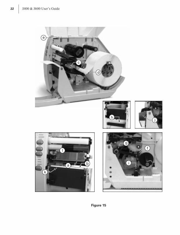
Refer to Figure 15 for cleaning locations.
S400 & S600 User’s Guide 21
Area Method Interval
Printhead (a) Alcohol
After every roll of media (or 500feet of fanfold media) whenprinting in the direct thermalmode.
After every roll of ribbon whenprinting in the thermal transfermode.
Platen roller (b) Alcohol
Media sensor (c) Air blow
Media path (d) Alcohol
Ribbon path (e) Air blow
Upper guide rod (f) (Peel-Off) Alcohol
Platen guide rod (g) (Peel-Off) Alcohol
Rewind power roller (h) (Peel-Off) Alcohol
Lower guide rod (i) (Peel-Off) Alcohol
CutterAssembly(j)(if used)
Cuttingcontinuous,pressure-sensitive media
Citrusbasedadhesiveremover
After every roll of media or moreoften, depending upon yourapplication and media.
Cutting tagstockor label backingmaterial only
Alcohol andair blow
After every 2 or 3 rolls of media.
Tear-Off/Peel-Off plate (k) Alcohol Once a month.
Label available sensor (l) Air blow Once every six months.
29
22 S400 & S600 User’s Guide
j
c
e
d
a b
lf
g
h
i
k
Figure 15
30
Cleaning the Exterior
The exterior surfaces of the printer may be cleaned with a lint-free cloth.Do not use harsh or abrasive cleaning agents or solvents. If necessary, amild detergent solution or desktop cleaner may be used sparingly.
Cleaning the Interior
Remove any accumulated dirt and lint from the interior of the printer usinga soft bristle brush and/or vacuum cleaner. Inspect this area after every rollof media.
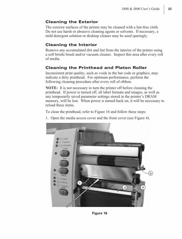
Cleaning the Printhead and Platen Roller
Inconsistent print quality, such as voids in the bar code or graphics, mayindicate a dirty printhead. For optimum performance, perform thefollowing cleaning procedure after every roll of ribbon.
NOTE: It is not necessary to turn the printer off before cleaning theprinthead. If power is turned off, all label formats and images, as well asany temporarily saved parameter settings stored in the printer’s DRAMmemory, will be lost. When power is turned back on, it will be necessary toreload these items.
To clean the printhead, refer to Figure 16 and follow these steps:
1. Open the media access cover and the front cover (see Figure 4).
S400 & S600 User’s Guide 23
a
c
b
d
Figure 16
31

2. Open the printhead (a) by moving the head open lever (b) to the openposition.
3. Remove the media and ribbon (if present).
4. With a swab, wipe the print elements (c) from end to end (the print ele-ments are the grayish/black strip just behind the chrome strip.) Allow afew seconds for the solvent to evaporate.
5. Rotate the platen roller (d) and clean thoroughly with alcohol.
6. Brush/vacuum any accumulated paper lint and dust away from the roll-ers and media sensors.
7. Reload ribbon and/or media, close and latch the printhead, close thefront cover and the media access cover, and continue printing.
If print quality has not improved after performing this procedure, trycleaning the printhead with Save-a-Printhead cleaning film. This speciallycoated material removes contamination buildup without damaging theprinthead. Call your authorized Zebra distributor for more information.
Cleaning the Cutter Module (for PrintersEquipped with the Optional Cutter)
The cutter module requires periodic cleaning to remove paper dust andgummed label residue. The procedure on the following pages should beperformed by the operator according to the cleaning schedule table.However, depending on your application and media type, you may need toclean the cutter more or less frequently.
NOTE: In the figures shown, media and ribbon have been removed forclarity. It is not necessary to remove media or ribbon before performing themaintenance procedures described.
IMPORTANT: Do not exchange cutter modules between differentprinters. The cutter module adjustments are optimized during installation towork with a particular printer and may not perform correctly if the moduleis placed on a different printer.
I. Removing the cutter module from the printer.
1. Turn off the printer’s AC power.
2.See Figure 17. Remove the label catch tray (a) by lifting it up and away fromthe front of the cutter module (b).
3. Raise the printer’s media access cover and lower the printer’s front cover.
4.See Figure 18. Gently pull straight down on the cutter cable connector (a) toremove it from the mating socket on the cutter module.
5.Turn the cutter mounting screw (b) with a screwdriver or by hand in acounterclockwise direction until it is loose.
6.See Figure 19. Hold the cutter module as shown. Apply gentle upward pressure tothe left and right ends while raising the cutter module up and away from themounting posts (a). If necessary, rock the module side to side to loosen it.
24 S400 & S600 User’s Guide
32

S400 & S600 User’s Guide 25
b
a
Figure 17
a
b
Figure 18
33

26 S400 & S600 User’s Guide
a
b
Figure 19
a
a
c
b
Figure 20
34
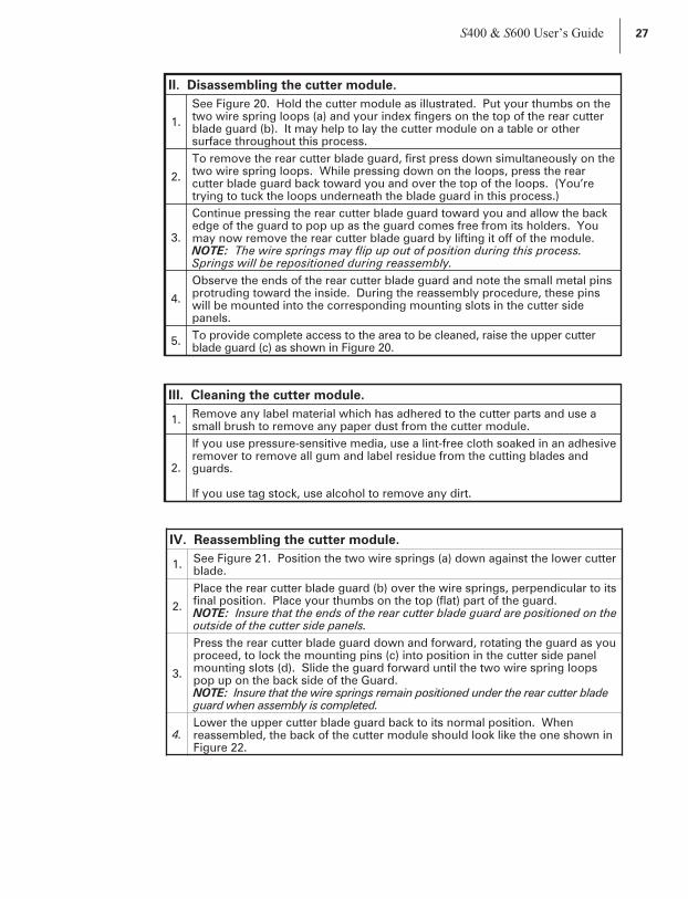
II. Disassembling the cutter module.
1.
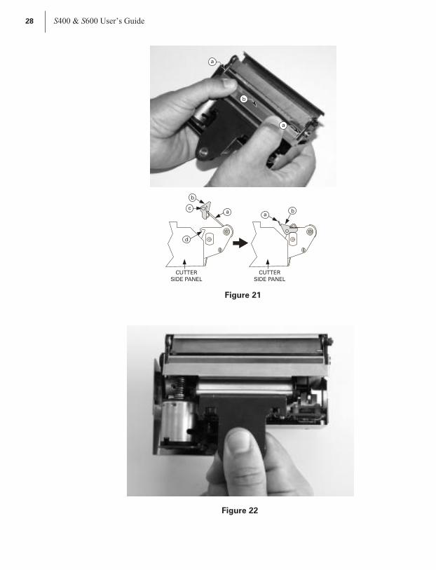
See Figure 20. Hold the cutter module as illustrated. Put your thumbs on thetwo wire spring loops (a) and your index fingers on the top of the rear cutterblade guard (b). It may help to lay the cutter module on a table or othersurface throughout this process.
2.
To remove the rear cutter blade guard, first press down simultaneously on thetwo wire spring loops. While pressing down on the loops, press the rearcutter blade guard back toward you and over the top of the loops. (You’retrying to tuck the loops underneath the blade guard in this process.)
3.
Continue pressing the rear cutter blade guard toward you and allow the backedge of the guard to pop up as the guard comes free from its holders. Youmay now remove the rear cutter blade guard by lifting it off of the module.NOTE: The wire springs may flip up out of position during this process.Springs will be repositioned during reassembly.
4.
Observe the ends of the rear cutter blade guard and note the small metal pinsprotruding toward the inside. During the reassembly procedure, these pinswill be mounted into the corresponding mounting slots in the cutter sidepanels.
5.To provide complete access to the area to be cleaned, raise the upper cutterblade guard (c) as shown in Figure 20.
III. Cleaning the cutter module.
1.Remove any label material which has adhered to the cutter parts and use asmall brush to remove any paper dust from the cutter module.
2.
If you use pressure-sensitive media, use a lint-free cloth soaked in an adhesiveremover to remove all gum and label residue from the cutting blades andguards.
If you use tag stock, use alcohol to remove any dirt.
IV. Reassembling the cutter module.
1.See Figure 21. Position the two wire springs (a) down against the lower cutterblade.
2.
Place the rear cutter blade guard (b) over the wire springs, perpendicular to itsfinal position. Place your thumbs on the top (flat) part of the guard.NOTE: Insure that the ends of the rear cutter blade guard are positioned on theoutside of the cutter side panels.
3.
Press the rear cutter blade guard down and forward, rotating the guard as youproceed, to lock the mounting pins (c) into position in the cutter side panelmounting slots (d). Slide the guard forward until the two wire spring loopspop up on the back side of the Guard.NOTE: Insure that the wire springs remain positioned under the rear cutter bladeguard when assembly is completed.
4.Lower the upper cutter blade guard back to its normal position. Whenreassembled, the back of the cutter module should look like the one shown inFigure 22.
S400 & S600 User’s Guide 27
35
28 S400 & S600 User’s Guide
a
aa
a
b
b
cb
CUTTER
SIDE PANEL
CUTTER
SIDE PANEL
d
Figure 21
Figure 22
36
V. Reinstalling the cutter module.
1.See Figure 19. Position the cutter module above the cutter mounting posts (a).Press down on the cutter module until the mounting slots (b) engage themounting posts on the printer.
2.See Figure 18. Tighten the mounting screw (b) in a clockwise direction tohold the cutter module in position.
3.See Figure 18. Position the cutter cable connector (a) so the flat side of theconnector faces away from the printer, then insert it up into the matingconnector on the cutter module.
4.Replace the cutter catch tray onto the two mounting posts located on thefront of the cutter module.
VI. Testing the Cutter Operation.
1.
If necessary, reload ribbon and label stock into the printer, then close theprinter’s front cover and media access cover.NOTE: When loading media, make sure the end of the label is positioned ontop of the platen roller, then close the printhead open lever.
2.When the printer is turned on, the cutter module will cycle through one cuttingoperation and be ready to print labels.
3.
OPTIONAL: Hold in the PAUSE button while turning on the printer’s AC power.When the Power ON Self Test begins (all LEDs on), release the PAUSE button.When the Power ON Self Test ends, the printer will automatically print test labelsthat the cutter module will automatically cut.
End of the cutter cleaning procedure.
S400 & S600 User’s Guide 29
37

Lubrication
No lubricating agents of any kind are required on this printer. Somecommercially available lubricants will damage the finish if used.
AC Power Fuse Replacement
A user-replaceable AC power fuse (see Figure 6) is located just to the left ofthe power on/off switch. For use with both voltage ranges, the replacementfuse is a 5x20 fast blow style rated at 5 Amp/250 VAC.
1. Before replacing the fuse, turn the AC power switch off and unplug theAC power cable.
2. To replace the fuse, insert the tip of a flathead screwdriver into the slotin the end of the fuse holder end cap.
3. Press in slightly on the end cap and turn the screwdriver slightly coun-terclockwise. This will disengage the end cap from the fuse holder andpermit the removal of the fuse.
4. To install a new fuse, reverse the procedure.
30 S400 & S600 User’s Guide
38

Mechanical Adjustments
This printer has been designed with minimal operator adjustments required.
Print Quality Adjustments
When changing from one media/ribbon combination to another, only slightchanges in print darkness or toggle pressure may be required. For thesesituations, refer to the toggle pressure adjustment in this chapter.
I. Checking the initial print quality.
1.Open the media access cover and front cover on the printer (seeFigure 4).
2.Load the recommended media and ribbon for your application and adjust themedia sensor position.
3.Send a label format to the printer or activate the PAUSE key self test (seeTroubleshooting), print a few labels, and press the PAUSE button to stopprinting.
4.Observe the print quality of the test labels. If it is satisfactory, exit the PAUSEkey self test by pressing and holding the CANCEL button until the DATA LEDgoes off. Otherwise, continue to step II.
II. Adjusting the print darkness (burn temperature).
1.Press the MODE button once (DARKEN and PAUSE LEDs turn on) to permitdarkness adjustment.
2. Press the PAUSE button to begin printing test labels.
3.While observing the print darkness, repeatedly press the UP (FEED) button tomake the printing darker, or the DOWN (CANCEL) button to make the printinglighter, until the desired darkness is achieved.
4.Briefly press the MODE button three times. The MODE LEDs will flash on andoff to indicate that the settings have been saved in memory.
5. Press the PAUSE button to stop printing.
NOTE: To confirm the change, turn off the printer. Then, turn on the printerwhile holding the CANCEL button.
If you are still experiencing poor print quality, perform the following togglepressure adjustment. Otherwise, exit the PAUSE key self test by pressingand holding the CANCEL button until the DATA LED goes off.
Toggle Pressure Adjustment
The toggle assembly presses the printhead against the ribbon (if used), themedia, and the platen.
S400 & S600 User’s Guide 31
39
The pressure applied by the toggle assembly may need to be increased orreduced when different thicknesses or widths of media are used in theprinter.
NOTE: Before increasing toggle pressure to achieve darker print darkness,perform the print quality adjustments.
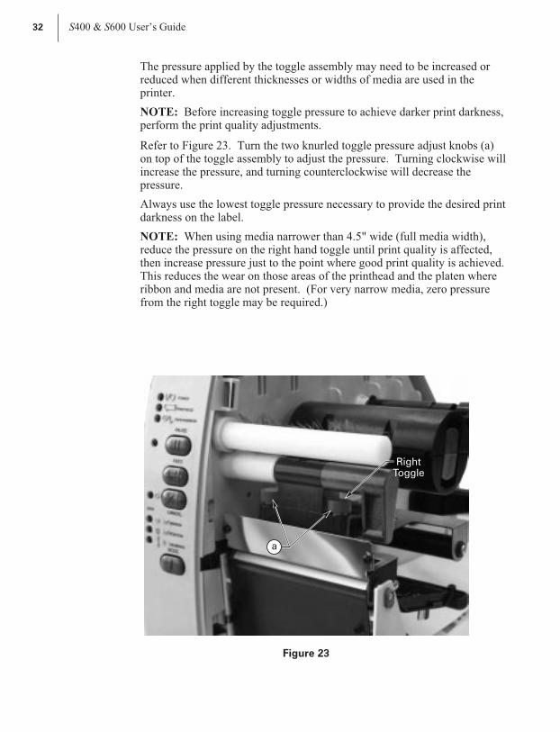
Refer to Figure 23. Turn the two knurled toggle pressure adjust knobs (a)on top of the toggle assembly to adjust the pressure. Turning clockwise willincrease the pressure, and turning counterclockwise will decrease thepressure.
Always use the lowest toggle pressure necessary to provide the desired printdarkness on the label.
NOTE: When using media narrower than 4.5" wide (full media width),reduce the pressure on the right hand toggle until print quality is affected,then increase pressure just to the point where good print quality is achieved.This reduces the wear on those areas of the printhead and the platen whereribbon and media are not present. (For very narrow media, zero pressurefrom the right toggle may be required.)
32 S400 & S600 User’s Guide
a
RightToggle
Figure 23
40
Media Rest Position Adjustment
This procedure sets the end-of-label position relative to the Tear-Off plateor cutter. Adjust this if your label is not being torn or cut at the correctpoint.
1. Briefly press the MODE button twice. The PAUSE and POSITIONLEDs turn on.
2. Press UP (FEED) or DOWN (CANCEL) to adjust the current setting.
3. Briefly press the MODE button twice. The MODE LEDs will flash on andoff to indicate that the settings have been saved in memory.
4. Press PAUSE to exit the pause mode. The PAUSE LED turns off.
Top of the Label Position Adjustment
This procedure positions the printing on the label relative to the top edge ofthe label. Adjust this if your printing is too close or too far away from thetop or bottom edge of the label.
1. Briefly press the MODE button twice, then press and hold it for aboutfive seconds until the lights change. The PAUSE, DARKEN, andCALIBRATE LEDs turn on.
2. Press UP (FEED) or DOWN (CANCEL) to adjust the current setting.
3. Briefly press the MODE button twice. The MODE LEDs will flash onand off to indicate that the settings have been saved in memory.
4. Press PAUSE to exit the pause mode. The PAUSE LED turns off.
Media Sensor Position Adjustment
This procedure is covered in Getting Ready to Print.
Ribbon Supply Spindle Adjustment
This procedure is covered in Getting Ready to Print.
S400 & S600 User’s Guide 33
41

Backing Rewind Power Roller Adjustment(PEEL-OFF OPTION REQUIRED)
NOTE: This roller is only present on printers with the Peel-Off option.Zebra presets this roller during manufacture for proper operation with mostapplications. Only adjust this roller when necessary.
In the Peel-Off mode, proper media tracking is critical. The rewind powerroller automatically turns along with the movement of media, to insurecontinuous rewind of the label backing material. When adjusting this roller,the operating position may vary due to the type, width, and thickness of thebacking material.
Before performing this adjustment, review the media loading procedure inGetting Ready to Print. Insure minimal sideways movement during theprinting process by positioning the left edge of the label backing even withthe edge guide mark on the tear-off/peel-off plate. Position the mediaguides against the outside (right) edge of the media, but not so tight as tobind the material.
When the power roller is properly adjusted, the backing material shouldhave even tension across its entire width and be wrapped snugly around allguides and rollers. If the tension is not even, the media/backing materialmay slide (walk) to the left or to the right as printing occurs. This can causeprint registration problems on the labels.
34 S400 & S600 User’s Guide
dec
b
a
LeftEdge
Up
Down
RightEdge
Figure 24
42

Figure 24 illustrates an improperly adjusted backing rewind powerroller (a). On the left side, the backing material (b) is not contacting thepower roller. The backing has more tension on the right edge (c) than onthe left edge (d).
Use a coin or screwdriver to turn the power roller adjustment (e). Theadjustment mechanism changes the position of the right end of the roller,while the left end is stationary. The right end moves up and down fortension balance.
Turning this adjustment in a counterclockwise direction causes the right endof the power roller to move down and increases the tension on the right sideof the backing material. (Turning the adjustment in a clockwise directionmoves the right end of the power roller up and decreases the tension on theright side.)
Balancing the tension increases the reliability of the printer to provideproperly printed labels by preventing the label backing from walking.
Use the FEED key self test (see Troubleshooting) or your own label formatto print several labels to insure tracking is maintained and tension on bothedges of the backing material remains consistent. Remember to removeeach label as it is automatically peeled away from the backing.
S400 & S600 User’s Guide 35
43

36 S400 & S600 User’s Guide
44

Troubleshooting
If the printer operates in an abnormal fashion, consult the troubleshootingtable below. The printer diagnostics following the troubleshooting tablemay also help you to determine the problem.
The troubleshooting of some problems may be beyond the abilities of theoperator. In these cases, call a service technician to perform additionaltroubleshooting and repair procedures.
Troubleshooting Table
Symptom Diagnosis Action
No LEDs turn on.
No AC powerapplied to theprinter.
Insure the AC power cable isconnected to a working voltagesource.
Faulty AC powerfuse.
Replace the fuse.
No voltageavailable from theinternal powersupply.
Call a service technician.
Printer locks up with allLEDs on when runningthe Power-on self test.
Hardware failure. Call a service technician.
CALIBRATE LED is off butall other LEDs are on.
Boot-block CRCerror.
Call a service technician.
CALIBRATE andPOSITION LEDs off butall other LEDs on.
DRAM error. Call a service technician.
CALIBRATE, POSITION,and DARKEN LEDs offbut all other LEDs on.
Firmwaredecompressionerror.
Call a service technician forinstructions on how to downloadand install firmware.
CALIBRATE, POSITION,DARKEN, and DATALEDs off but all otherLEDs on.
Firmware error.
CALIBRATE, POSITION,DARKEN, DATA, andPAUSE LEDs off but allother LEDs on.
Firmware error.
S400 & S600 User’s Guide 37
45
Symptom Diagnosis Action
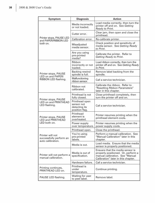
Printer stops, PAUSE LEDand PAPER/RIBBON LEDboth on.
Media incorrectlyor not loaded.
Load media correctly, then turn theprinter off and on. See GettingReady to Print.
Cutter error.Clear jam, then open and close theprinthead.
Calibration error. Re-calibrate printer.
Misadjustedmedia sensor.
Check position and sensitivity ofmedia sensor. See Getting Readyto Print.
Are you usingpre-printedmedia?
Calibrate the printer. Refer toGetting Ready to Print.
Printer stops, PAUSELED on and PAPER/RIBBON LED flashing.
Ribbonincorrectly or notloaded.
Load ribbon correctly, then turn theprinter off and on. See Getting Readyto Print.
Backing rewindspindle is full.
Remove label backing from thespindle.
Malfunctioningribbon sensor.
Call a service technician.
Ribbon notcalibrated.
Calibrate the ribbon. Refer to“Resetting Ribbon Parameters”later in this chapter.
Printer stops, PAUSELED on and PRINTHEADLED flashing.
Printhead is notfully closed.
Close printhead completely, thenturn the printer off and on.
Printhead opensensor notdetecting itsposition flag.
Call a service technician.
Printer stops, PAUSELED and PRINTHEADLED both on.
Printheadelement isoverheated.
Printer resumes printing when theprinthead element cools.
Power supplyover temperature.
Printer resumes printing when thepower supply cools.
Printer will notsuccessfully perform anauto calibration.
Printhead open. Close the printhead.
You’re usingpre-printedlabels.
Perform a manual calibration. See“Manual Calibration” later in thischapter.
Media is out.Load media. Ensure that the mediasensor is properly positioned.
Printer will not perform amanual calibration.
Media is out ofspecification.
Ensusre that the media sensor isproperly positioned. Or, perform amanual calibration. See “ManualCalibration” later in this chapter.
Hardware failure. Call a service technician.
Printing continues,PRINTHEAD LED on.
Printhead isundertemperature.
Continue printing.
PAUSE LED flashing.Waiting for userto peel label.
Remove label.
38 S400 & S600 User’s Guide
46

Symptom Diagnosis Action
DATA LED is singleflashing.
CANCEL buttonwas pressed anda format wasdeleted.
No action required.
PAUSE LED and DATALED alternately flashing,but all other LEDs on.
Firmware error.Call a service technician forinstructions on how to downloadand install firmware.
DATA LED is flashing.Printer isreceiving data.
Printing resumes when data isreceived.
DATA LED is slowflashing.
Printer sent a“stoptransmitting” tothe hostcomputer.
No action required.
Dots missing in printedarea of label.
Dirty printhead.Clean the printhead. See RoutineCare and Adjustments.
Printheadelement goingbad. Print qualityproblems.
Call a service technician.
Print width setincorrectly.
Default the printer. Refer to“Resetting Factory Defaults” later inthis chapter.
Loss of printingregistration on labels.
For Peel-Off mode:
Possible mediasensor problem.
Adjust media sensor position andcall a service technician ifnecessary.
Printer set fornon-continuousmedia, butcontinuous medialoaded.
Set printer for correct media. SeeGetting Ready to Print.
Improperlyadjusted mediaedge guides orpower roller.
Refer to Getting Ready to Print andRoutine Care and Adjustments forproper positioning andadjustments.
Excessive vertical drift intop-of-form registration.
Incorrect medialoading or mediasensoradjustments.
See “Loading the Media” or“Adjusting the Media Sensor” inGetting Ready to Print.
Light vertical linesapproximately .006 widerunning through alllabels.
Dirty head orribbon rollers.
See “Printhead Cleaning” inRoutine Care and Adjustments.
Defective printheadelements.
Call a service technician.
Light printing or noprinting on the left orright side of the label.
Printhead needsbalancing.
Adjust balance. See “TogglePressure Adjustment” in RoutineCare and Adjustments.
Short printed lines at 45°to label edge on left orright side of label.
Too muchprintheadpressure.
Reduce the pressure. See “TogglePressure Adjustment” in RoutineCare and Adjustments.
S400 & S600 User’s Guide 39
47
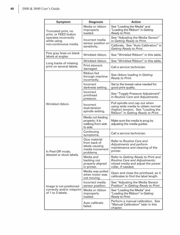
Symptom Diagnosis Action
Truncated print, noprint, or FEED buttonoperates incorrectlywhile usingnon-continuous media.
Media or ribbonimproperlyloaded.
See “Loading the Media” and“Loading the Ribbon” in GettingReady to Print.
Incorrect mediasensor position orsensitivity.
See “Adjusting the Media Sensor”in Getting Ready to Print.
Calibrate. See “Auto Calibration” inGetting Ready to Print.
Fine gray lines on blanklabels at angles.
Wrinkled ribbon. See “Wrinkled Ribbon” in this table.
Long tracks of missingprint on several labels.
Wrinkled ribbon. See “Wrinkled Ribbon” in this table.
Print elementdamaged.
Call a service technician.
Wrinkled ribbon.
Ribbon fedthrough machineincorrectly.
See ribbon loading in GettingReady to Print.
Incorrectdarkness setting.
Set to the lowest value needed forgood print quality.
Incorrectprintheadpressure.
See “Toggle Pressure Adjustment”in Routine Care and Adjustments.
Incorrectdual-tensionspindle setting.
Pull spindle end cap out whenusing wide media to obtain normal(higher) tension. See “Loading theRibbon” in Getting Ready to Print.
Media not feedingproperly; it iswalking from sideto side.
Make sure the media is snug byadjusting the media guides.
Continuingsymptoms.
Call a service technician.
In Peel-Off mode,skewed or stuck labels.
Glue materialfrom back oflabels causingmedia movementproblems.
Refer to Routine Care andAdjustments and performmaintenance and cleaning of theprinter.
Media andbacking notproperly alignedin printer.
Refer to Getting Ready to Print andRoutine Care and Adjustments;reload media and adjust the powerroller, if needed.
Image is not positionedcorrectly and/or misprintof 1 to 3 labels.
Media was pulledwhen motor wasnot moving.
Open and close the printhead, so itcalibrates to find the label length.
Incorrect mediasensor position.
See “Adjusting the Media SensorPosition” in Getting Ready to Print.
Media or ribbonimproperlyloaded.
See “Loading the Media” and“Loading the Ribbon” in GettingReady to Print.
Auto calibratefailed.
Perform a manual calibration. See“Manual Calibration” later in thischapter.
40 S400 & S600 User’s Guide
48
Symptom Diagnosis Action
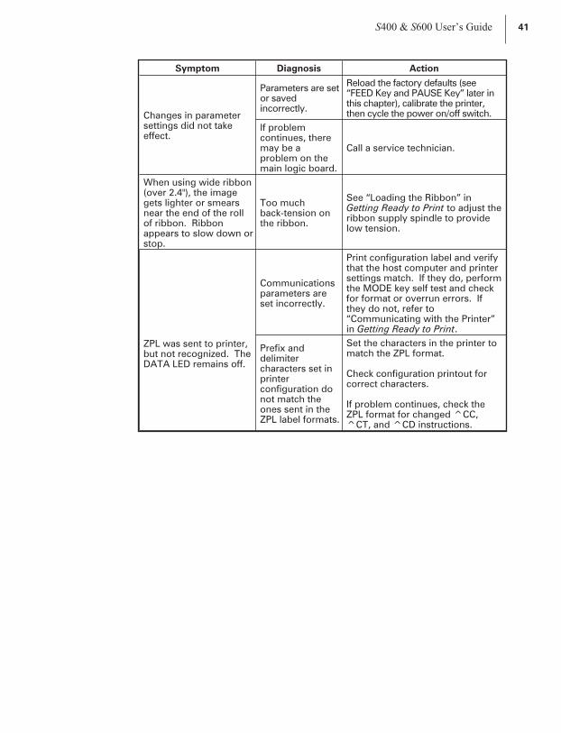
Changes in parametersettings did not takeeffect.
Parameters are setor savedincorrectly.
Reload the factory defaults (see“FEED Key and PAUSE Key” later inthis chapter), calibrate the printer,then cycle the power on/off switch.
If problemcontinues, theremay be aproblem on themain logic board.
Call a service technician.
When using wide ribbon(over 2.4"), the imagegets lighter or smearsnear the end of the rollof ribbon. Ribbonappears to slow down orstop.
Too muchback-tension onthe ribbon.
See “Loading the Ribbon” inGetting Ready to Print to adjust theribbon supply spindle to providelow tension.
ZPL was sent to printer,but not recognized. TheDATA LED remains off.
Communicationsparameters areset incorrectly.
Print configuration label and verifythat the host computer and printersettings match. If they do, performthe MODE key self test and checkfor format or overrun errors. Ifthey do not, refer to“Communicating with the Printer”in Getting Ready to Print.
Prefix anddelimitercharacters set inprinterconfiguration donot match theones sent in theZPL label formats.
Set the characters in the printer tomatch the ZPL format.
Check configuration printout forcorrect characters.
If problem continues, check theZPL format for changed ^CC,^CT, and ^CD instructions.
S400 & S600 User’s Guide 41
49

In cutter mode, skewed,stuck, improperly cut orpartially cut labels.
Cutter is dirty.Follow cutter cleaning procedure inRoutine Care and Adjustments.
Cutter blades aredull.
Call a service technician.
The cutter is jammingup with labels, or labelsare being cut more thanonce.
Cutter is dirty.Follow cutter cleaning procedure inRoutine Care and Adjustments.
Label length istoo short.
Increase label length.
Labels are not being cutat all.
Cutter option notenabled.
See Routine Care andAdjustments.
Connecting cablenot connected tocutter module.
With printer power off, plug cableinto cutter module.
Printing stops,PAPER/RIBBON, PAUSE,and CANCEL LEDs on.
Out of media. Load media.
For printers with thecutter option installed.
Media jammed incutter.
Remove media, clean cuttermodule if necessary.
Cutter module isdirty.
Clean cutter module. See RoutineCare and Adjustments.
End of the medianot positionedcorrectly on top ofplaten.
Reposition media so that the end ison top of the platen. See GettingReady to Print.
If error condition persists after attempting each of theabove solutions, call a service technician.
42 S400 & S600 User’s Guide
50
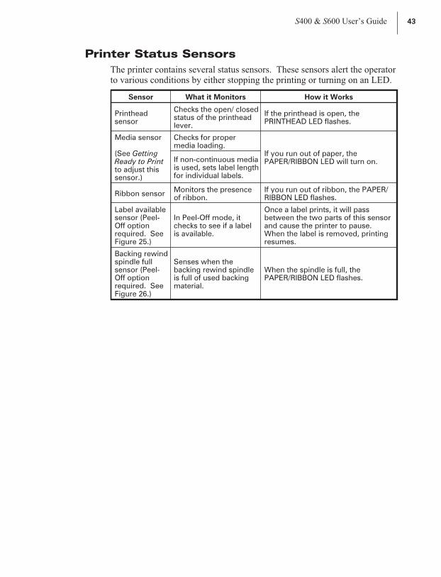
Printer Status Sensors
The printer contains several status sensors. These sensors alert the operatorto various conditions by either stopping the printing or turning on an LED.
Sensor What it Monitors How it Works
Printheadsensor
Checks the open/ closedstatus of the printheadlever.
If the printhead is open, thePRINTHEAD LED flashes.
Media sensor
(See GettingReady to Printto adjust thissensor.)
Checks for propermedia loading.
If you run out of paper, thePAPER/RIBBON LED will turn on.If non-continuous media
is used, sets label lengthfor individual labels.
Ribbon sensorMonitors the presenceof ribbon.
If you run out of ribbon, the PAPER/RIBBON LED flashes.
Label availablesensor (Peel-Off optionrequired. SeeFigure 25.)
In Peel-Off mode, itchecks to see if a labelis available.
Once a label prints, it will passbetween the two parts of this sensorand cause the printer to pause.When the label is removed, printingresumes.
Backing rewindspindle fullsensor (Peel-Off optionrequired. SeeFigure 26.)
Senses when thebacking rewind spindleis full of used backingmaterial.
When the spindle is full, thePAPER/RIBBON LED flashes.
S400 & S600 User’s Guide 43
51

44 S400 & S600 User’s Guide
Edge Guide Mark
Tear-Off/
Peel-Off
Plate
Label
Available
Sensor
Figure 25
RewindSpindle Full
Sensor
Figure 26
52

Manual Calibration
Perform a manual calibration whenever you are using pre-printedmedia, if the printer is in manual calibration mode, or when the printerwill not auto calibrate.
During this procedure, the media type, label length, media and ribbonsensor settings, and printing method are determined. Media type isdetermined by sensing either continuous or non-continuous media as blanklabels move through the printer. If non-continuous media is sensed, labellength is also calibrated. If ribbon is sensed, the thermal transfer printmethod is configured; otherwise, the direct thermal print method isconfigured.
The results of this calibration are stored in the printer’s memory and areretained even if printer power is removed. These parameters remain ineffect until the next calibration is performed.
NOTES: This procedure should only be done once to put the printer intomanual calibration. After that, press the MODE button three times and theFEED button once when you change media (a label will print that shows thesensor profile).
If the printer is in the Peel-Off mode, the operator must “catch” the labels asthey are peeled away from the backing during this procedure.
1. Place the head open lever in the open position.
2. Remove the ribbon.
3. Remove approximately 6” of labels from the media roll, enough so thatonly the backing material is threaded under the media sensor when themedia is loaded.
4. Reload the media.
5. Press and hold down the PAUSE, FEED, and CANCEL buttons.
6. Turn on the power switch.
7. After the CALIBRATE LED goes out, release the PAUSE, FEED, andCANCEL buttons.
8. When the PRINTHEAD LED flashes, reload the ribbon.
9. Make sure the media sensor is properly positioned.
10.Close the printhead.
11.A media and ribbon sensor profile will print.
NOTE: To return to Auto Calibration, press and hold the PAUSE,CANCEL, and MODE buttons when you turn on the printer.
S400 & S600 User’s Guide 45
53
Resetting Printer Parameters
Resetting Factory Defaults
If it is ever necessary to reset all of the factory default values, press andhold the FEED and PAUSE buttons while turning on the power.Permanently save these values in memory by pressing the MODE buttonfour times; the DARKEN, POSITION, and CALIBRATE LEDs will flash,indicating the changes have been saved. To return to printing mode, turnoff and then turn on the printer.
Resetting Communications Parameters
Pressing and holding the FEED, PAUSE, and MODE buttons while turningon the power resets only the communications parameters to 9600 baud, 8 bitword length, no parity, and 1 stop bit. Permanently save these values inmemory by pressing the MODE button four times; the DARKEN,POSITION, and CALIBRATE LEDs will flash, indicating the changes havebeen saved.
Resetting Ribbon Parameters
If it is ever necessary to reset the ribbon parameters to the factory defaultvalues, follow this procedure:
1. Turn off the printer.
2. Open the printhead and remove the ribbon.
3. Turn on the printer while pressing and holding the FEED, CANCEL,and MODE buttons.
4. After the PRINTHEAD LED flashes, reload the ribbon.
5. Close the printhead.
NOTE: A label automatically prints, showing the ribbon sensor profile.
6. To save, press the MODE button four times.
46 S400 & S600 User’s Guide
54

Printer Diagnostics
Power-On Self Test
A Power-On Self Test (POST) is performed automatically each time the printeris turned on. This test checks for proper initialization of various electroniccircuits and establishes starting parameters as those stored in the printer’smemory. During this test sequence, the front panel lights will turn on and off toinsure proper operation.
At the end of this self test, only the POWER LED will remain lit. If otherLEDs are also lit, refer to the troubleshooting table.
Additional Printer Self Tests
These self tests produce sample labels and provide specific information thathelp the operator determine the operating conditions for the printer.
Each self test is enabled by holding in a specific front panel button whileturning the power switch on. Keep the button depressed until theCALIBRATE LED goes out. When the Power-On Self Test is complete,the selected printer self test will automatically start. To return to printingmode, turn off and then turn on the printer.
NOTES:
n When performing self tests, disconnect all communications interfacecables from the printer.
n When canceling a self test before its actual completion, always turn theprinter power switch off and back on.
n When performing these self tests while in the Peel-Off mode, theoperator must remove the labels as they become available.
n When the cutter option is installed and enabled, the labels printed inthese self tests should be automatically cut as they are printed.
S400 & S600 User’s Guide 47
55

CANCEL Key Self Test
This self test prints the printer’s configuration parameters (for example,printing darkness, label length, and media type) that are currently stored inconfiguration (Flash) memory. See Figure 27.
To perform the CANCEL key self test:
1. Press the CANCEL button while turning on the printer.
2. Release the button when the CALIBRATE LED turns off.
3. To return to printing mode, turn off and then turn on the printer.
48 S400 & S600 User’s Guide
Figure 27
56

PAUSE Key Self Test
This self test can be used to provide the test labels required when makingadjustments to the printer’s mechanical assemblies. See Figure 28.
To perform the PAUSE key self test:
1. Press the PAUSE button while turning on the printer.
2. Release the button when the front panel LEDs turn on.
3. To return to printing mode, turn off and then turn on the printer.
NOTE: This self test consists of four individual test features:
n The initial self test prints 15 labels at 2.4”/second then automaticallypauses the printer. Each time the PAUSE button is pressed, anadditional 15 labels will print, up to 9999 labels.
n While the printer is paused, pressing the CANCEL button once alters theself test. Now each time the PAUSE button is pressed, the printer prints15 labels at maximum speed, up to 9999 labels.
n While the printer is paused, pressing the CANCEL button a second timealters the self test again. Now each time the PAUSE button is pressed,the printer prints 50 labels at 2.4”/second, up to 9999 labels.
n While the printer is paused, pressing the CANCEL button alters the selftest a third time. Now each time the PAUSE button is pressed, theprinter prints 50 labels at maximum speed, up to 9999 labels.
S400 & S600 User’s Guide 49
Figure 28
57
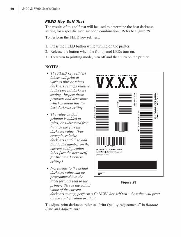
FEED Key Self Test
The results of this self test will be used to determine the best darknesssetting for a specific media/ribbon combination. Refer to Figure 29.
To perform the FEED key self test:
1. Press the FEED button while turning on the printer.
2. Release the button when the front panel LEDs turn on.
3. To return to printing mode, turn off and then turn on the printer.
NOTES:
n The FEED key self testlabels will print atvarious plus or minusdarkness settings relativeto the current darknesssetting. Inspect theseprintouts and determinewhich printout has thebest darkness setting.
n The value on thatprintout is added to(plus) or subtracted from(minus) the currentdarkness value. (Forexample, relativedarkness is “5,” so addthat to the number on thecurrent configurationlabel [see the next step]for the new darknesssetting.)
n Increments to the actualdarkness value can beprogrammed into thelabel formats sent to theprinter. To see the actualvalue of the currentdarkness setting, perform a CANCEL key self test: the value will printon the configuration printout.
To adjust print darkness, refer to “Print Quality Adjustments” in RoutineCare and Adjustments.
50 S400 & S600 User’s Guide
Figure 29
58
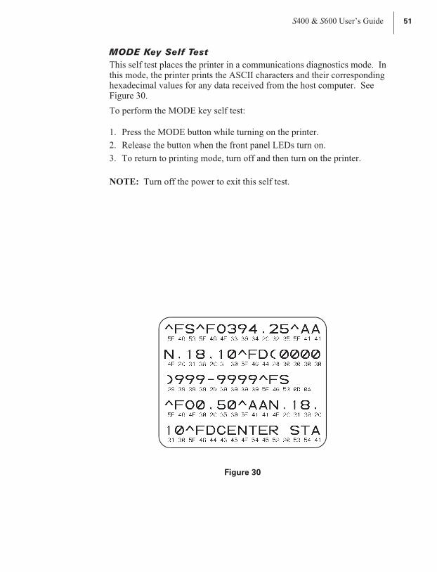
MODE Key Self Test
This self test places the printer in a communications diagnostics mode. Inthis mode, the printer prints the ASCII characters and their correspondinghexadecimal values for any data received from the host computer. SeeFigure 30.
To perform the MODE key self test:
1. Press the MODE button while turning on the printer.
2. Release the button when the front panel LEDs turn on.
3. To return to printing mode, turn off and then turn on the printer.
NOTE: Turn off the power to exit this self test.
S400 & S600 User’s Guide 51
Figure 30
59

52 S400 & S600 User’s Guide
60
Specifications
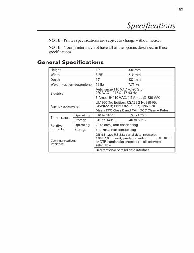
NOTE: Printer specifications are subject to change without notice.
NOTE: Your printer may not have all of the options described in thesespecifications.
General Specifications
Height 13" 330 mm
Width 8.25" 210 mm
Depth 17" 432 mm
Weight (option-dependent) 17 lbs 7.71 kg
Electrical
Auto range 110 VAC +/-20% or230 VAC +/-15%, 47-63 Hz
3 Amps @ 110 VAC, 1.5 Amps @ 230 VAC
Agency approvals
UL1950 3rd Edition; CSA22.2 No950-95;CISPR22-B; EN50082-1:1997; EN60950
Meets FCC Class B and CAN.DOC Class A Rules
TemperatureOperating 40 to 105° F 5 to 40° C
Storage -40 to 140° F -40 to 60° C
Relativehumidity
Operating 20 to 85%, non-condensing
Storage 5 to 85%, non-condensing
CommunicationsInterface
DB-9S-type RS-232 serial data interface;110-57,600 baud; parity, bits/char. and XON-XOFFor DTR handshake protocols -- all softwareselectable
Bi-directional parallel data interface
S400 & S600 User’s Guide 53
61

Printing Specifications
Printing Specifications S400 Printer S600 Printer
Resolution 203 dots per inch (8 dots per mm)
Dot size (square) 0.005" (0.127 mm)
Maximum print width 4.09" (104 mm)
Print lengthMinimum 0.005" (0.127 mm)
Maximum 36" (914 mm) 39" (991 mm)
Bar code modulus (“X”)dimension
5 mil to 55 mil
Programmable constantprinting speeds
2" (51 mm)
3” (76 mm)
4” (102 mm)
2" (51 mm)
3" (76 mm)
4" (102 mm)
5" (127 mm)
6" (152 mm)
DRAM memory 1MB 2MB
Flash memory (E:) n/a 1MB
Ribbon Specifications
Ribbon width (werecommend using ribbonat least as wide as themedia to protect theprinthead from wear).
Minimum 1.57" 40 mm
Maximum 4.5" 114 mm
Standardlengths
2:1 media to ribbon roll ratio 984’ 300 m
3:1 media to ribbon roll ratio 1476’ 450 m
Ribbon core inside diameter 1.0" 25 mm
Maximum ribbon roll diameter 3.2" 81 mm
54 S400 & S600 User’s Guide
62
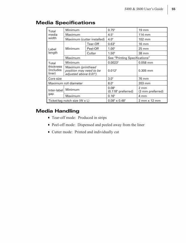
Media Specifications
Totalmediawidth
Minimum 0.75" 19 mm
Maximum 4.5" 114 mm
Maximum (cutter installed) 4.0" 102 mm
Labellength
Minimum
Tear-Off 0.63" 16 mm
Peel-Off 1.00" 25 mm
Cutter 1.50" 38 mm
Maximum See “Printing Specifications”
Totalthickness(includesliner)
Minimum 0.0023" 0.058 mm
Maximum (printheadposition may need to beadjusted above 0.01")
0.012" 0.305 mm
Core size 3.0" 76 mm
Maximum roll diameter 8.0" 203 mm
Inter-labelgap
Minimum0.08"(0.118" preferred)
2 mm(3 mm preferred)
Maximum 0.16" 4 mm
Ticket/tag notch size (W x L) 0.08" x 0.48" 2 mm x 12 mm
Media Handling
n Tear-off mode: Produced in strips
n Peel-off mode: Dispensed and peeled away from the liner
n Cutter mode: Printed and individually cut
S400 & S600 User’s Guide 55
63

Options
n 4 MB flash expansion
n 8 MB flash expansion
n *Peel-Off mode with backing-only rewind feature
n *Cutter with label catch tray
n Scalable and bitmap smooth fonts available for text
n Ethernet
* Factory installed
Contact your authorized Zebra distributor for information.
Zebra Programming Language (ZPL II)
56 S400 & S600 User’s Guide
n Downloadable graphics(with data compression)
n Bit image data transfer andprinting, mixed text/graphics
n Format inversion
n Mirror image printing
n Four-position field rotation(0°, 90°, 180°, 270°)
n Slew command
n Programmable quantity withprint pause
n Communicates in printable ASCIIcharacters
n Controlled via mainframe, mini,PC, Portable Data Terminal
n Serialized fields
n In-Spec OCR-A and OCR-B
n UPC/EAN (nominal 100%magnification)
64
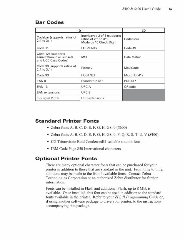
Bar Codes
Standard Printer Fonts
n Zebra fonts A, B, C, D, E, F, G, H, GS, 0 (S600)
n Zebra fonts A, B, C, D, E, F, G, H, GS, 0, P, Q, R, S, T, U, V (S400)
n CG Triumvirate Bold Condensed scalable smooth font
n IBM Code Page 850 International characters
Optional Printer Fonts
There are many optional character fonts that can be purchased for yourprinter in addition to those that are standard in the unit. From time to time,additions may be made to the list of available fonts. Contact ZebraTechnologies Corporation or an authorized Zebra distributor for furtherinformation.
Fonts can be installed in Flash and additional Flash, up to 8 MB, isavailable. Once installed, this font can be used in addition to the standardfonts available in the printer. Refer to your ZPL II Programming Guide or,if using another software package to drive your printer, to the instructionsaccompanying that package.
S400 & S600 User’s Guide 57
1D 2D
Codabar (supports ratios of2:1 to 3:1)
Interleaved 2 of 5 (supportsratios of 2:1 to 3:1,Modulus 10 Check Digit)
Codablock
Code 11 LOGMARS Code 49
Code 128 (supportsserialization in all subsetsand UCC Case Codes)
MSI Data Matrix
Code 39 (supports ratios of2:1 to 3:1)
Plessey MaxiCode
Code 93 POSTNET MicroPDF417
EAN 8 Standard 2 of 5 PDF 417
EAN 13 UPC-A QRcode
EAN extensions UPC-E
Industrial 2 of 5 UPC extensions
65

58 S400 & S600 User’s Guide
66

Appendix
RS-232 Connector Technical Information
NOTE: When XON/XOFF handshaking is selected, data flow is controlledby the ASCII control codes DC1 (XON) and DC3 (XOFF). The DTRcontrol lead will have no effect.
Interconnecting to DTE Devices
The printer is configured as data terminal equipment (DTE). To connect theprinter to other DTE devices (such as the serial port of a personalcomputer), use an RS-232 null modem (crossover) cable. Figure 31 showsthe required cable connections.
Interconnecting to DCE Devices
When the printer is connected via its RS-232 interface to datacommunication equipment (DCE) such as a modem, a STANDARDRS-232 (straight-through) interface cable must be used. Figure 32 showsthe connections required for this cable.
S400 & S600 User’s Guide 59
RS-232 Connector Pinouts
Pin. No. Description
1 Not used
2 RXD (receive data) input to the printer
3 TXD (transmit data) output from the printer
4DTR (data terminal ready) output from the printer --controls when the host may send data
5 Chassis ground
6 DSR (data set ready) input to the printer
7RTS (request to send) output from the printer -- always inthe ACTIVE condition when the printer is turned on
8 Not used
9 5 V fused
67

60 S400 & S600 User’s Guide
1
(TD) (TD)
(RD) (RD)
(RTS) (RTS)
(DSR) (DSR)
(SG) (SG)
(DTR) (DTR)
DTE DTE
1
2 2
3 3
4 4
5 5
6 6
7 7
8 8
9 9
Figure 31
TRANSMIT DATA (TD)
RECEIVE DATA (RD)
REQUEST TO SEND (RTS)
CLEAR TO SEND (CTS)
DATA SET READY (DSR)
SIGNAL GROUND (SG)
CARRIER DETECT (CD)
DATA TERMINAL READY (DTR)
1
DCE DTE
1
2 2
3 3
4 4
5 5
6 6
7 7
8 8
9 9
Figure 32
68
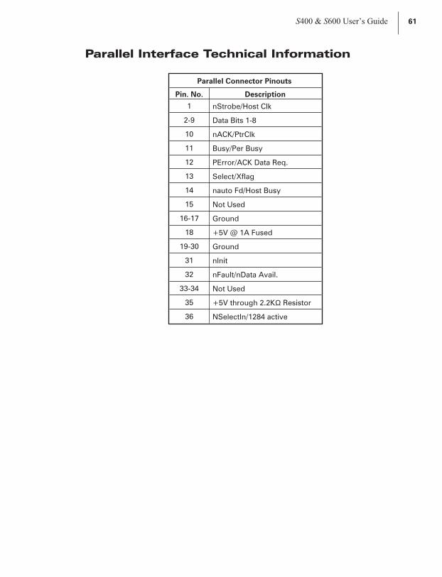
Parallel Interface Technical Information
S400 & S600 User’s Guide 61
Parallel Connector Pinouts
Pin. No. Description
1 nStrobe/Host Clk
2-9 Data Bits 1-8
10 nACK/PtrClk
11 Busy/Per Busy
12 PError/ACK Data Req.
13 Select/Xflag
14 nauto Fd/Host Busy
15 Not Used
16-17 Ground
18 +5V @ 1A Fused
19-30 Ground
31 nlnit
32 nFault/nData Avail.
33-34 Not Used
35 +5V through 2.2KΩ Resistor
36 NSelectIn/1284 active
69

Storage and Reshipping
If you are not placing the printer into operation immediately, repackage itusing the original packing materials. The printer may be stored under thefollowing conditions:
n Temperature: -40° to 140° F (-40 to 60° C)
n Relative humidity: 5% to 85% non-condensing
To ship the printer, carefully pack it in a suitable container to avoid damageduring transit. Whenever possible, use the original container from thefactory. A shipping container can be purchased from Zebra TechnologiesCorporation, if the original one has been lost or destroyed.
If you use a different container, package the printer carefully to avoiddamage.
CAUTION: When packaging the printer in a rigid container, use shock
mounts or shock-absorbing packing material. A rigid container will allow
shock on the outside to be transmitted undamped to the printer which may
cause damage. Also, before packing, remove all ribbon and media from the
supply and take-up spindles to prevent damage to the printer.
62 S400 & S600 User’s Guide
70
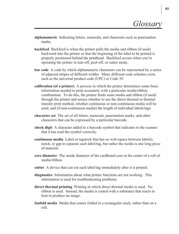
Glossary
alphanumeric Indicating letters, numerals, and characters such as punctuation
marks.
backfeed Backfeed is when the printer pulls the media and ribbon (if used)
backward into the printer so that the beginning of the label to be printed is
properly positioned behind the printhead. Backfeed occurs when you’re
operating the printer in tear-off, peel-off, or cutter mode.
bar code A code by which alphanumeric characters can be represented by a series
of adjacent stripes of different widths. Many different code schemes exist,
such as the universal product code (UPC) or Code 39.
calibration (of a printer) A process in which the printer determines some basic
information needed to print accurately with a particular media/ribbon
combination. To do this, the printer feeds some media and ribbon (if used)
through the printer and senses whether to use the direct thermal or thermal
transfer print method, whether continuous or non-continuous media will be
used, and (if non-continuous media) the length of individual labels/tags.
character set The set of all letters, numerals, punctuation marks, and other
characters that can be expressed by a particular barcode.
check digit A character added to a barcode symbol that indicates to the scanner
that it has read the symbol correctly.
continuous media Label or tagstock that has no web (space between labels),
notch, or gap to separate each label/tag, but rather the media is one long piece
of material.
core diameter The inside diameter of the cardboard core at the center of a roll of
media/ribbon.
cutter A device that can cut each label/tag immediately after it is printed.
diagnostics Information about what printer functions are not working. This
information is used for troubleshooting problems.
direct thermal printing Printing in which direct thermal media is used. No
ribbon is used. Instead, the media is coated with a substance that reacts to
heat to produce an image.
fanfold media Media that comes folded in a rectangular stack, rather than on a
roll.
S400 & S600 User’s Guide 63
71

font A complete set of alphanumeric characters in one style of type. Example:
Times, Helvetica.
ips “inches-per-second” The speed at which the label or tag is printed. Zebra
offers printers that can print from 2 ips to 12 ips.
label An adhesive-backed piece of paper, plastic, or other material on which
information is printed.
label available sensor For printers equipped with the Peel-Off option, this sensor
detects a printed label waiting to be taken or “picked” by the operator. While
it detects this label, the printer will not print additional labels. Once the label
has been taken, printing resumes. Also called “take-label sensor.”
label backing (label liner) The material on which labels are affixed during
manufacture and which is discarded or recycled by the end-users. Label
backing (or liner) has a non-stick surface that allows the label to be easily
removed by the end-user and placed in the desired location.
media Material onto which data is printed by the printer. Types of media include:
tagstock, continuous, fanfold, roll, etc.
media sensor This sensor is located behind the printhead to detect the presence of
media and, for non-continuous media, the position of the web, hole, or notch
that separates each label.
media supply spindle The rotating arm that supports media rolls and provides
consistent media feed to the printhead.
non-volatile memory Electronic memory that retains data even when power is
removed.
print speed The speed at which printing occurs. For thermal transfer printers,
this speed is expressed in terms of ips (inches per second).
printhead wear The degradation of the surface of the printhead and/or the print
elements over time. Heat and abrasion can cause printhead wear. Therefore,
to maximize the life of your printhead use the lowest print darkness setting
(sometimes called “burn temperature” or “head temperature”) and the lowest
printhead/toggle pressure necessary. Also, use ribbon that is as wide or wider
than the media, to protect the printhead from the rougher media.
registration Alignment of printing with respect to the top of a label/tag.
ribbon A band of inked material that is pressed by the printhead against the
media to transfer an image onto the media, which in turn is pressed against the
platen. A ribbon consists of a base film coated with wax or resin “ink.” Zebra
64 S400 & S600 User’s Guide
72

ribbons also have a back coating that protects the printhead from damage.
The ribbon transfers ink onto the media when heated by the printhead.
ribbon wrinkle A wrinkling of the ribbon caused by improper alignment of the
strip plate and/or printhead pressure. This wrinkle can be seen just above the
strip plate. Ribbon wrinkle can cause voids in the print and/or the spent
ribbon to rewind unevenly. This is a condition that should be corrected by
performing adjustment procedures.
roll media Media that comes supplied rolled up on a core (usually cardboard).
Contrast this with fanfold media, which comes folded in a rectangular stack.
Supplies Supplies is a general term for ribbon and media.
Tag A type of media having no adhesive backing but featuring a hole or notch by
which the tag can be hung on something. Usually tags are made of cardboard
or other durable material.
take label sensor See “label available sensor.”
thermal direct printing See “direct thermal printing.”
thermal transfer printing A printing method in which the printhead heats an
ink- or resin-coated ribbon against the media, causing the ink/resin to transfer
onto the media. By selectively heating the ribbon, you can form an image on
the media. See also “ribbon.”
void A space where printing should have occurred but, due to some error
condition, it did not occur. A void can cause a bar code symbol to be read
incorrectly or to not be read at all.
S400 & S600 User’s Guide 65
73

66 S400 & S600 User’s Guide
74

Index
A
AC power cable . . . . . . . . . . . 5
AC power fuse, replacing. . . . . . 30
Adjustments
Backing rewind power roller . . 34
Label top position . . . . . . . . 33
Media rest position . . . . . . . 33
Media sensor . . . . . . . . . . 15
Media sensor position. . . . . . 33
Print darkness . . . . . . . . . . 31
Print quality . . . . . . . . . . . 31
Print quality check . . . . . . . 31
Ribbon supply spindle . . . . . 33
Toggle pressure . . . . . . . . . 31
ASCII control codes
XON/XOFF . . . . . . . . . . . 59
Autobaud . . . . . . . . . . . . . . 20
Auto calibration. . . . . . . . . . . 16
B
Backing rewind power roller,
adjusting . . . . . . . . . . . . 34
Bar codes . . . . . . . . . . . . . . 57
Burn temperature, adjusting . . . . 31
C
Cabling requirements, serial
and parallel . . . . . . . . . . . 19
Calibration, automatic . . . . . . . 16
Calibration, manual . . . . . . . . . 45
Cleaning
Cutter module . . . . . . . . . . 24
Exterior . . . . . . . . . . . . . 23
Interior . . . . . . . . . . . . . 23
Maintenance schedule . . . . . 21
Platen roller . . . . . . . . . . . 23
Printhead . . . . . . . . . . . . 23
Communications parameters,
resetting . . . . . . . . . . . . . 46
Communications parameters,
setting . . . . . . . . . . . . . . 19
Cutter mode . . . . . . . . . . . . . 3
Cutter module, cleaning
Cleaning. . . . . . . . . . . . . 27
Disassembling. . . . . . . . . . 27
Reassembling . . . . . . . . . . 27
Reinstalling . . . . . . . . . . . 29
Removing . . . . . . . . . . . . 24
Testing . . . . . . . . . . . . . 29
D
Damage, reporting . . . . . . . . . . 1
Darkness, adjusting . . . . . . . . . 31
Defaulting the printer . . . . . . . . 19
DCE devices . . . . . . . . . . . . 59
DTE devices . . . . . . . . . . . . 59
E
Electrical noise . . . . . . . . . . . 19
S400 & S600 User’s Guide 67
75
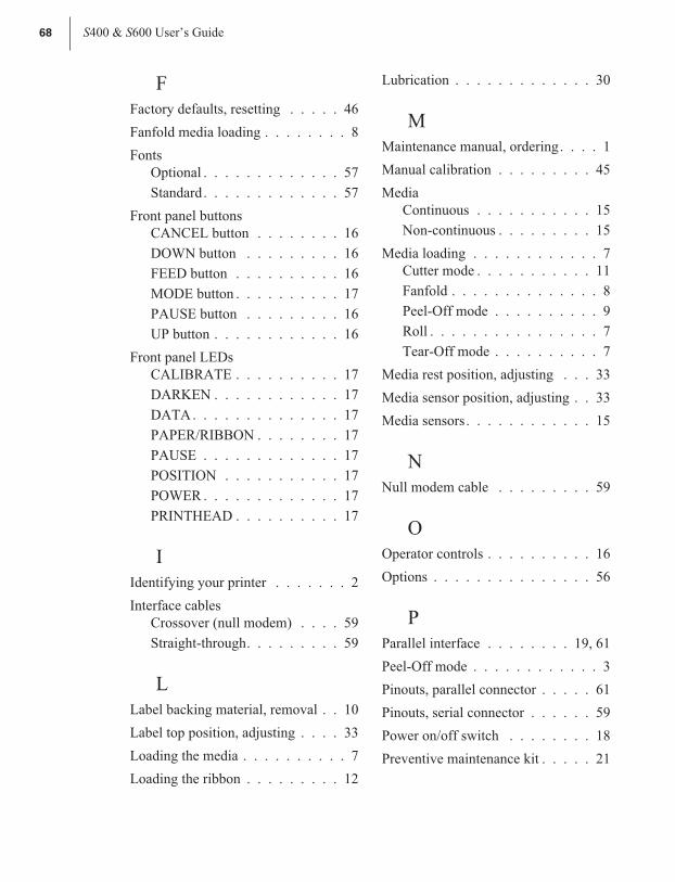
F
Factory defaults, resetting . . . . . 46
Fanfold media loading . . . . . . . . 8
Fonts
Optional . . . . . . . . . . . . . 57
Standard. . . . . . . . . . . . . 57
Front panel buttons
CANCEL button . . . . . . . . 16
DOWN button . . . . . . . . . 16
FEED button . . . . . . . . . . 16
MODE button . . . . . . . . . . 17
PAUSE button . . . . . . . . . 16
UP button . . . . . . . . . . . . 16
Front panel LEDs
CALIBRATE . . . . . . . . . . 17
DARKEN . . . . . . . . . . . . 17
DATA. . . . . . . . . . . . . . 17
PAPER/RIBBON . . . . . . . . 17
PAUSE . . . . . . . . . . . . . 17
POSITION . . . . . . . . . . . 17
POWER . . . . . . . . . . . . . 17
PRINTHEAD . . . . . . . . . . 17
I
Identifying your printer . . . . . . . 2
Interface cables
Crossover (null modem) . . . . 59
Straight-through. . . . . . . . . 59
L
Label backing material, removal . . 10
Label top position, adjusting . . . . 33
Loading the media . . . . . . . . . . 7
Loading the ribbon . . . . . . . . . 12
Lubrication . . . . . . . . . . . . . 30
M
Maintenance manual, ordering. . . . 1
Manual calibration . . . . . . . . . 45
Media
Continuous . . . . . . . . . . . 15
Non-continuous . . . . . . . . . 15
Media loading . . . . . . . . . . . . 7
Cutter mode . . . . . . . . . . . 11
Fanfold . . . . . . . . . . . . . . 8
Peel-Off mode . . . . . . . . . . 9
Roll . . . . . . . . . . . . . . . . 7
Tear-Off mode . . . . . . . . . . 7
Media rest position, adjusting . . . 33
Media sensor position, adjusting . . 33
Media sensors. . . . . . . . . . . . 15
N
Null modem cable . . . . . . . . . 59
O
Operator controls . . . . . . . . . . 16
Options . . . . . . . . . . . . . . . 56
P
Parallel interface . . . . . . . . 19, 61
Peel-Off mode . . . . . . . . . . . . 3
Pinouts, parallel connector . . . . . 61
Pinouts, serial connector . . . . . . 59
Power on/off switch . . . . . . . . 18
Preventive maintenance kit . . . . . 21
68 S400 & S600 User’s Guide
76

Printer diagnostics
CANCEL key self test . . . . . 48
FEED key self test . . . . . . . 50
MODE key self test . . . . . . . 51
PAUSE key self test . . . . . . 49
Power-on self test . . . . . . . . 47
Printer identification . . . . . . . . . 2
Printer status sensors
Backing rewind spindle full. . . 43
Label available . . . . . . . . . 43
Media . . . . . . . . . . . . . . 43
Printhead . . . . . . . . . . . . 43
Ribbon . . . . . . . . . . . . . 43
Printer/computer connections
Parallel . . . . . . . . . . . . . 19
Serial . . . . . . . . . . . . . . 18
R
Removing the ribbon . . . . . . . . 14
Reporting damage . . . . . . . . . . 1
Resetting communications
parameters . . . . . . . . . . . . 46
Resetting factory defaults. . . . . . 46
Resetting ribbon parameters . . . . 46
Reshipping . . . . . . . . . . . . . 62
Ribbon loading . . . . . . . . . . . 12
Ribbon parameters, resetting . . . . 46
Ribbon removal . . . . . . . . . . . 14
Ribbon supply spindle
Low-tension position . . . . . . 12
Normal position . . . . . . . . . 12
Ribbon supply spindle, adjusting . . 33
Roll media loading . . . . . . . . . . 7
S
^SC command . . . . . . . . . . . 20
Sensors . . . . . . . . . . . . . . . 15
Serial communications port. . . . . 59
Serial interface . . . . . . . . . 18, 59
Site requirements. . . . . . . . . . . 2
Software, selecting . . . . . . . . . 20
Specifications
General . . . . . . . . . . . . . 53
Media . . . . . . . . . . . . . . 55
Media handling . . . . . . . . . 55
Printing . . . . . . . . . . . . . 54
Ribbon . . . . . . . . . . . . . 54
Storage . . . . . . . . . . . . . . . 62
T
Tear-Off mode . . . . . . . . . . . . 2
Test label, printing . . . . . . . . . 18
Toggle pressure, adjusting . . . . . 31
Troubleshooting table. . . . . . . . 37
U
Unpacking . . . . . . . . . . . . . . 1
V
Ventilation . . . . . . . . . . . . . . 2
Z
ZPL II Programming Guide,
ordering . . . . . . . . . . . . . . 1
S400 & S600 User’s Guide 69
77

70 S400 & S600 User’s Guide
78


