ZED-F9R u-blox F9 high precision sensor fusion GNSS receiver Interface description Abstract This document describes the interface (version 33.20) of the ZED- F9R, a high precision sensor fusion GNSS receiver. www.u-blox.com UBX-19056845 - R01 C1-Public
Transcript
ZED-F9Ru-blox F9 high precision sensor fusion GNSS receiver
Interface description
AbstractThis document describes the interface (version 33.20) of the ZED-F9R, a high precision sensor fusion GNSS receiver.
www.u-blox.com
UBX-19056845 - R01C1-Public
ZED-F9R - Interface description
Document informationTitle ZED-F9R
Subtitle u-blox F9 high precision sensor fusion GNSS receiver
Document type Interface description
Document number UBX-19056845
Revision and date R01 28-Oct-2020
Document status Advance information
Disclosure restriction C1-Public
This document applies to the following products:
Product name Type number Firmware version PCN reference
ZED-F9R ZED-F9R-01B-00 HPS 1.20 N/A
u-blox reserves all rights to this document and the information contained herein. Products, names, logos and designsdescribed herein may in whole or in part be subject to intellectual property rights. Reproduction, use, modification ordisclosure to third parties of this document or any part thereof without the express permission of u-blox is strictly prohibited.
The information contained herein is provided "as is" and u-blox assumes no liability for the use of the information. No warranty,either express or implied, is given with respect to, including but not limited to, the accuracy, correctness, reliability and fitnessfor a particular purpose of the information. This document may be revised by u-blox at any time. For most recent documents,please visit www.u blox.com.
2.5.1 NMEA Talker ID............................................................................................................................ 202.5.2 NMEA extra fields........................................................................................................................ 202.5.3 NMEA latitude and longitude format...................................................................................... 212.5.4 NMEA GNSS, satellite and signal numbering........................................................................212.5.5 NMEA position fix flags..............................................................................................................212.5.6 NMEA output of invalid or unknown data.............................................................................. 22
2.6 NMEA messages overview..................................................................................................................232.7 Standard messages............................................................................................................................. 23
2.7.1 DTM.................................................................................................................................................232.7.1.1 Datum reference..................................................................................................................23
2.7.2 GAQ................................................................................................................................................. 242.7.2.1 Poll a standard message (Talker ID GA)......................................................................... 24
2.7.3 GBQ................................................................................................................................................. 242.7.3.1 Poll a standard message (Talker ID GB)......................................................................... 24
2.7.5 GGA................................................................................................................................................. 262.7.5.1 Global positioning system fix data..................................................................................26
2.7.6 GLL.................................................................................................................................................. 262.7.6.1 Latitude and longitude, with time of position fix and status.....................................27
2.7.7 GLQ..................................................................................................................................................272.7.7.1 Poll a standard message (Talker ID GL)......................................................................... 27
2.7.8 GNQ................................................................................................................................................. 272.7.8.1 Poll a standard message (Talker ID GN).........................................................................28
2.7.10 GPQ............................................................................................................................................... 292.7.10.1 Poll a standard message (Talker ID GP)....................................................................... 29
UBX-19056845 - R01
Contents Page 3 of 209C1-Public Advance information
ZED-F9R - Interface description
2.7.11 GQQ...............................................................................................................................................292.7.11.1 Poll a standard message (Talker ID GQ)...................................................................... 29
2.7.12 GRS............................................................................................................................................... 302.7.12.1 GNSS range residuals...................................................................................................... 30
2.7.13 GSA............................................................................................................................................... 302.7.13.1 GNSS DOP and active satellites....................................................................................30
2.7.18 THS............................................................................................................................................... 342.7.18.1 True heading and status.................................................................................................34
2.7.19 TXT................................................................................................................................................342.7.19.1 Text transmission............................................................................................................. 35
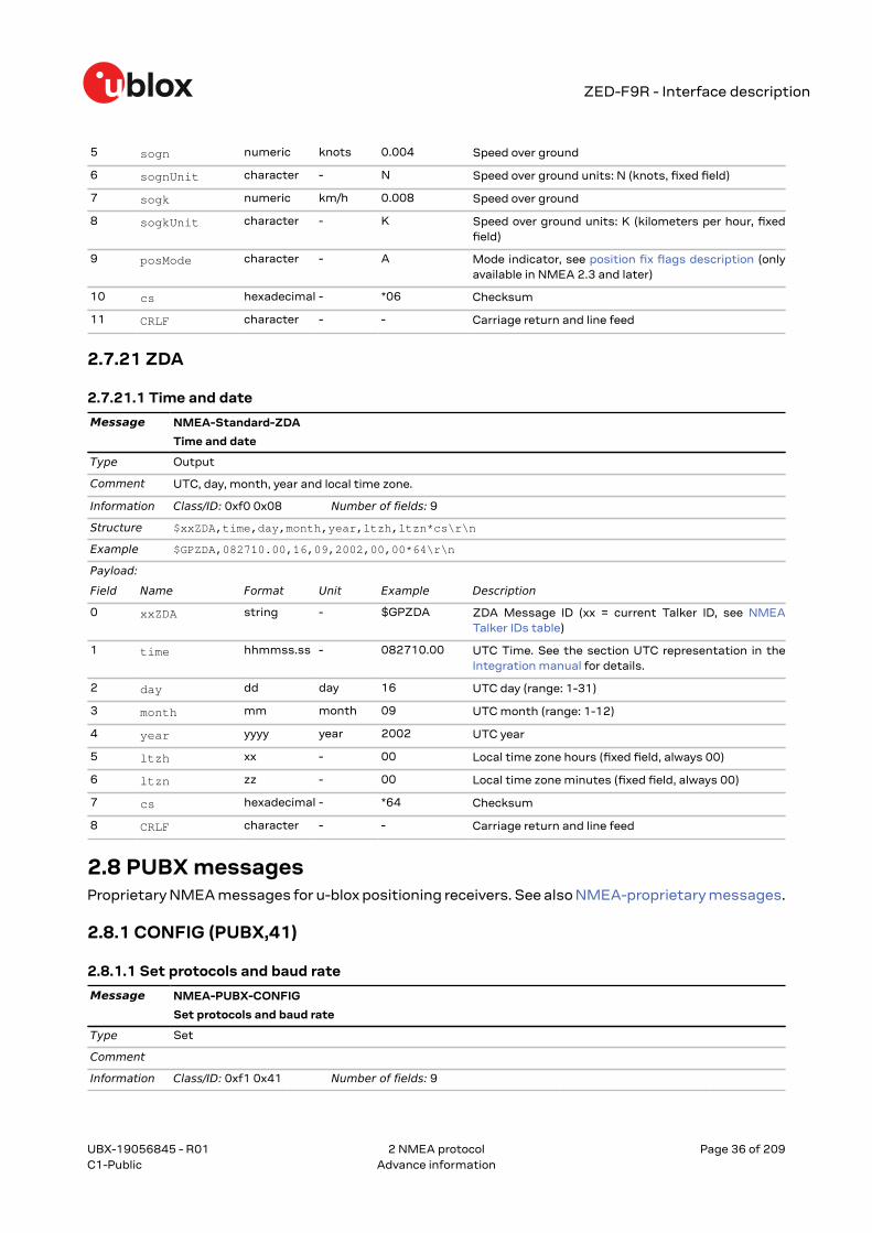
2.7.20 VTG............................................................................................................................................... 352.7.20.1 Course over ground and ground speed........................................................................ 35
2.7.21 ZDA............................................................................................................................................... 362.7.21.1 Time and date................................................................................................................... 36
2.8.1.1 Set protocols and baud rate............................................................................................. 362.8.2 POSITION (PUBX,00)................................................................................................................... 37
2.8.2.1 Poll a PUBX,00 message....................................................................................................372.8.3 RATE (PUBX,40)........................................................................................................................... 37
2.8.3.1 Set NMEA message output rate..................................................................................... 372.8.4 SVSTATUS (PUBX,03)................................................................................................................. 38
2.8.4.1 Poll a PUBX,03 message....................................................................................................382.8.5 TIME (PUBX,04)............................................................................................................................39
2.8.5.1 Poll a PUBX,04 message....................................................................................................39
3.10.2.1 Configure and start a sensor production test............................................................ 493.10.3 UBX-CFG-VALDEL (0x06 0x8c).............................................................................................. 49
3.12.4 UBX-INF-TEST (0x04 0x03).....................................................................................................603.12.4.1 ASCII output with test contents................................................................................... 60
3.14.1.1 Communication port information..................................................................................813.14.2 UBX-MON-GNSS (0x0a 0x28)................................................................................................. 82
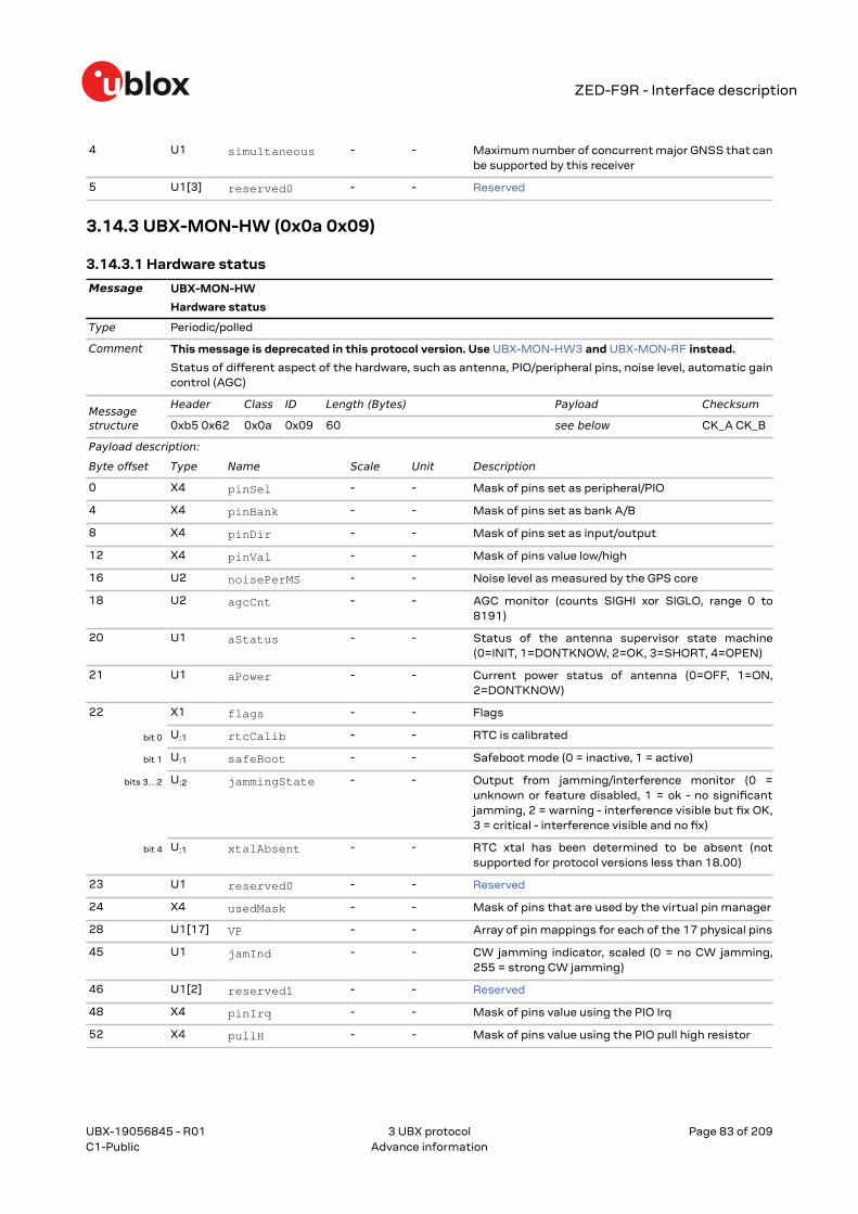
3.14.2.1 Information message major GNSS selection..............................................................823.14.3 UBX-MON-HW (0x0a 0x09)..................................................................................................... 83
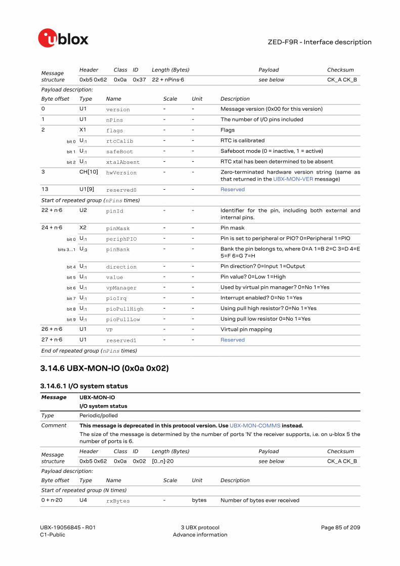
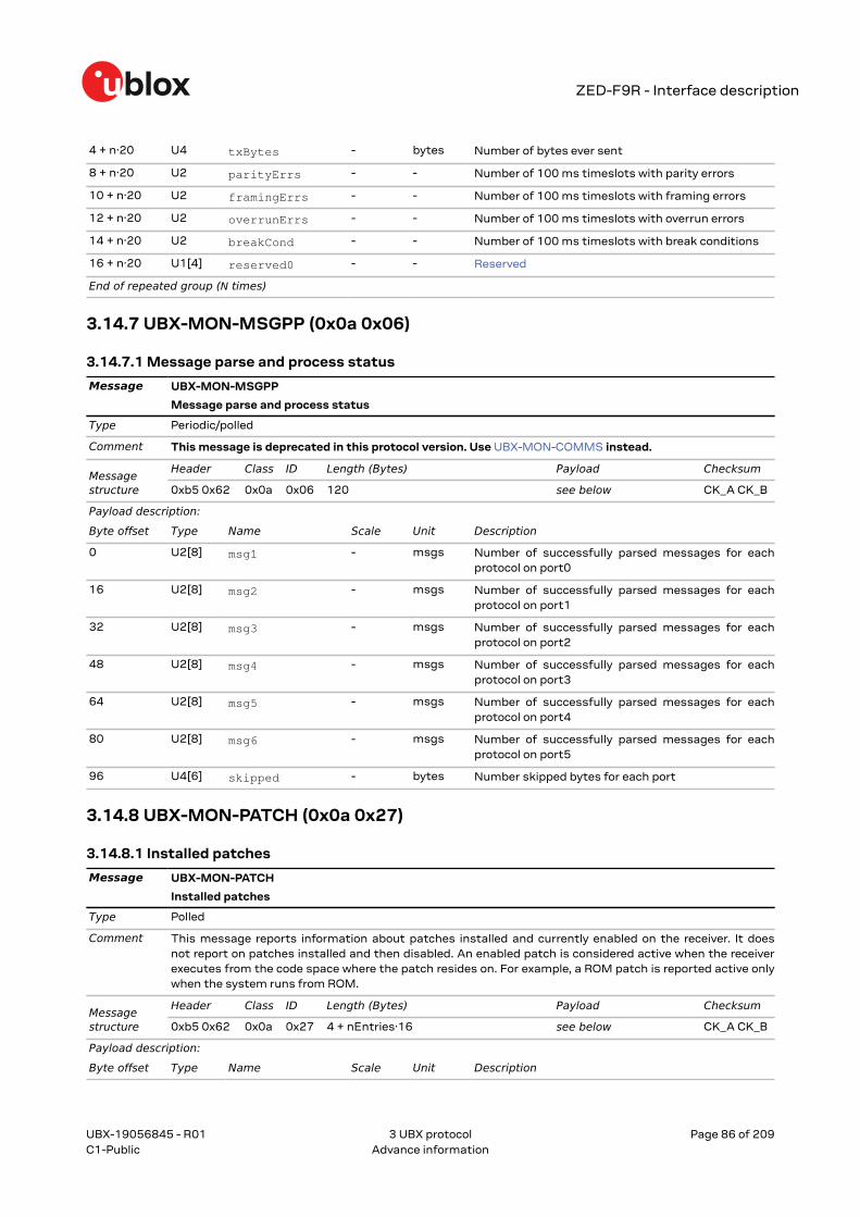
3.14.6.1 I/O system status............................................................................................................. 853.14.7 UBX-MON-MSGPP (0x0a 0x06)..............................................................................................86
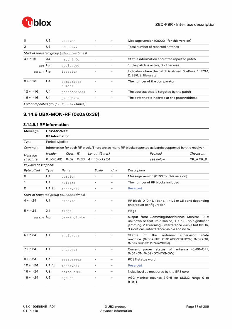
3.14.7.1 Message parse and process status..............................................................................863.14.8 UBX-MON-PATCH (0x0a 0x27)............................................................................................... 86
3.15.4.1 Dilution of precision..........................................................................................................943.15.5 UBX-NAV-EELL (0x01 0x3d)................................................................................................... 95
3.15.5.1 Position error ellipse parameters.................................................................................. 953.15.6 UBX-NAV-EOE (0x01 0x61)..................................................................................................... 95
3.15.6.1 End of epoch...................................................................................................................... 953.15.7 UBX-NAV-GEOFENCE (0x01 0x39)........................................................................................96
3.15.8.1 High precision position solution in ECEF.....................................................................963.15.9 UBX-NAV-HPPOSLLH (0x01 0x14)........................................................................................ 97
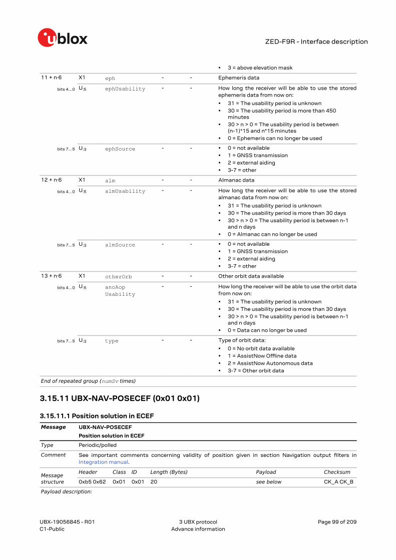
3.15.9.1 High precision geodetic position solution................................................................... 973.15.10 UBX-NAV-ORB (0x01 0x34)...................................................................................................98
3.15.11.1 Position solution in ECEF..............................................................................................993.15.12 UBX-NAV-POSLLH (0x01 0x02).........................................................................................100
3.15.12.1 Geodetic position solution......................................................................................... 1003.15.13 UBX-NAV-PVT (0x01 0x07)................................................................................................ 100
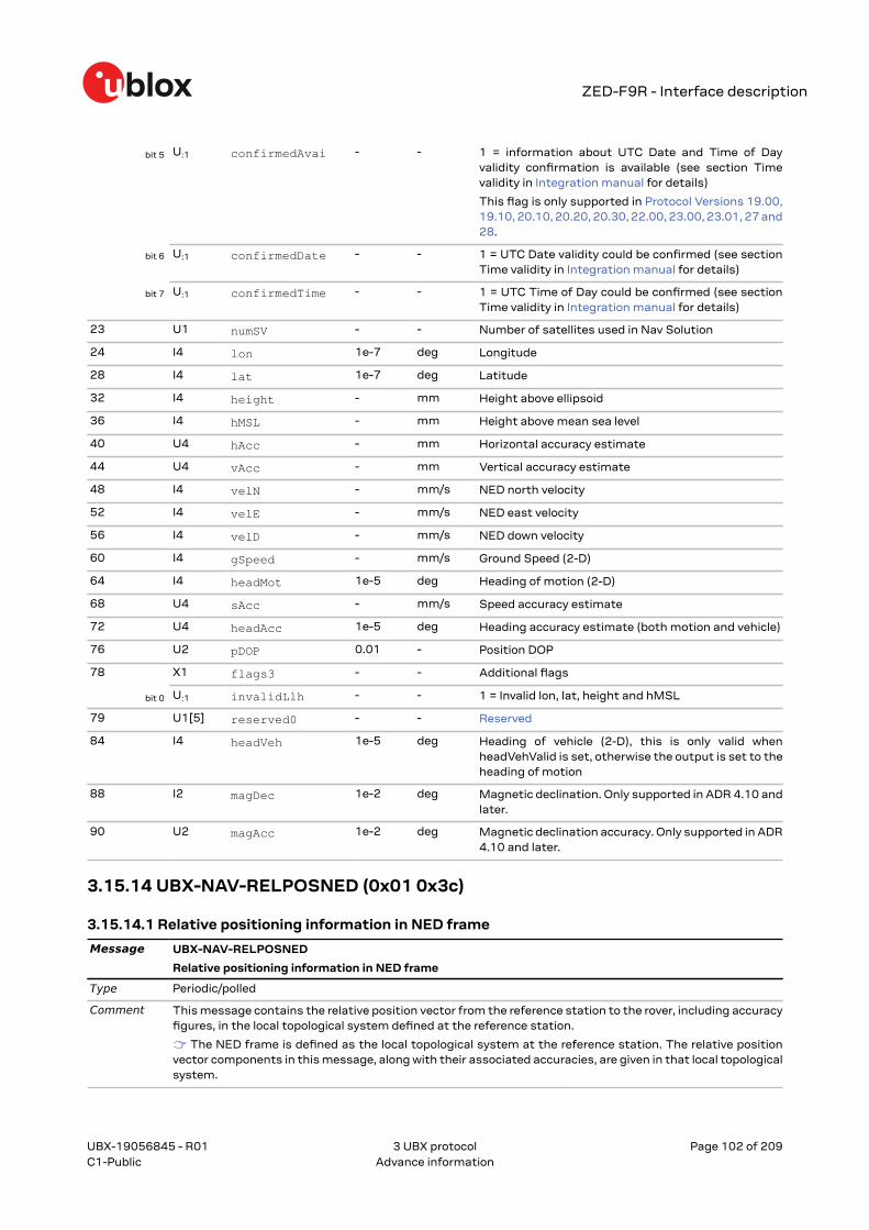
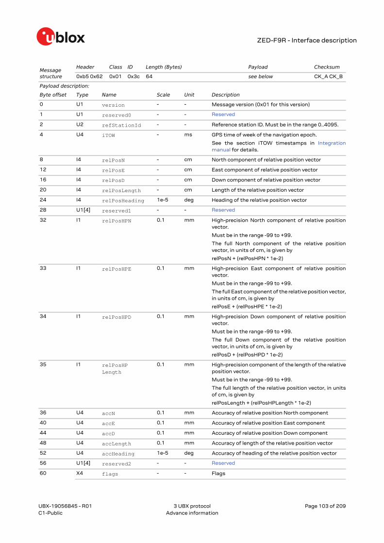
3.15.13.1 Navigation position velocity time solution............................................................. 1003.15.14 UBX-NAV-RELPOSNED (0x01 0x3c).................................................................................102
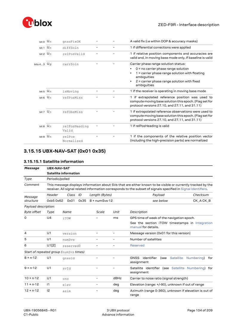
3.15.14.1 Relative positioning information in NED frame..................................................... 1023.15.15 UBX-NAV-SAT (0x01 0x35).................................................................................................104
3.15.20.1 BeiDou time solution................................................................................................... 1113.15.21 UBX-NAV-TIMEGAL (0x01 0x25).......................................................................................111
3.15.21.1 Galileo time solution....................................................................................................1113.15.22 UBX-NAV-TIMEGLO (0x01 0x23).......................................................................................112
3.15.22.1 GLONASS time solution............................................................................................. 1123.15.23 UBX-NAV-TIMEGPS (0x01 0x20).......................................................................................112
3.15.23.1 GPS time solution........................................................................................................ 1123.15.24 UBX-NAV-TIMELS (0x01 0x26)..........................................................................................113
3.15.24.1 Leap second event information................................................................................ 1133.15.25 UBX-NAV-TIMEQZSS (0x01 0x27).................................................................................... 114
3.15.25.1 QZSS time solution..................................................................................................... 1153.15.26 UBX-NAV-TIMEUTC (0x01 0x21).......................................................................................115
3.15.26.1 UTC time solution........................................................................................................ 1153.15.27 UBX-NAV-VELECEF (0x01 0x11).......................................................................................116
3.15.27.1 Velocity solution in ECEF............................................................................................1163.15.28 UBX-NAV-VELNED (0x01 0x12)........................................................................................ 116
3.15.28.1 Velocity solution in NED frame................................................................................. 1173.16 UBX-RXM (0x02).............................................................................................................................. 117
3.16.1 UBX-RXM-MEASX (0x02 0x14)............................................................................................ 1173.16.1.1 Satellite measurements for RRLP.............................................................................. 117
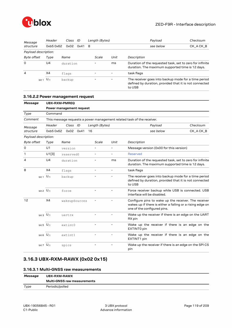
3.16.2 UBX-RXM-PMREQ (0x02 0x41)............................................................................................1183.16.2.1 Power management request........................................................................................1183.16.2.2 Power management request........................................................................................119
3.16.3 UBX-RXM-RAWX (0x02 0x15).............................................................................................. 1193.16.3.1 Multi-GNSS raw measurements................................................................................. 119
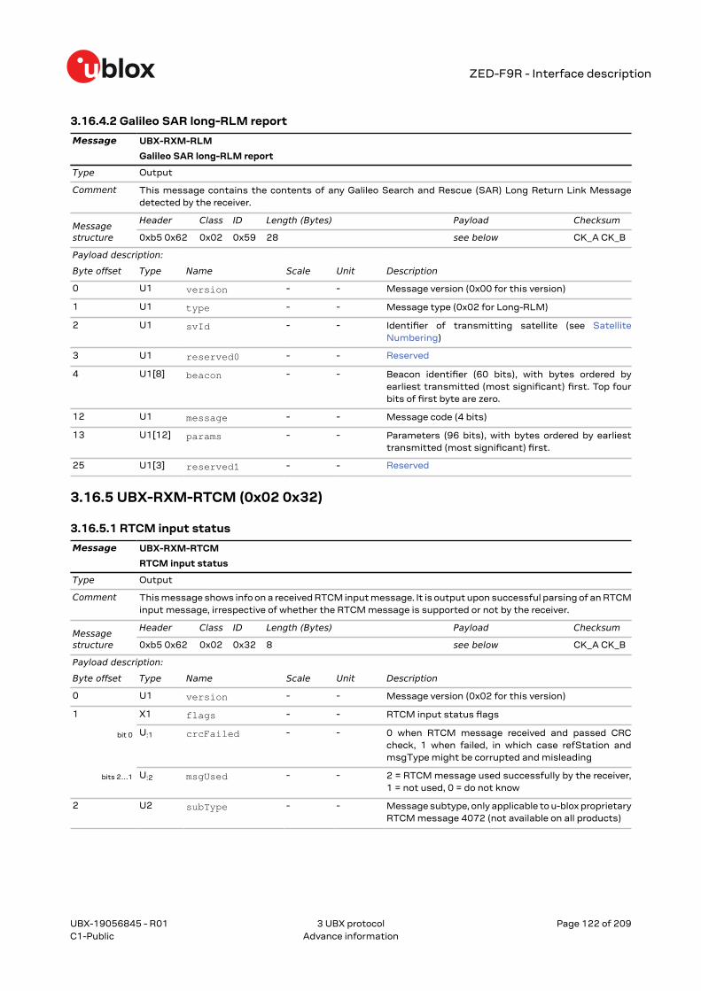
3.16.4 UBX-RXM-RLM (0x02 0x59)................................................................................................. 1213.16.4.1 Galileo SAR short-RLM report..................................................................................... 1213.16.4.2 Galileo SAR long-RLM report....................................................................................... 122
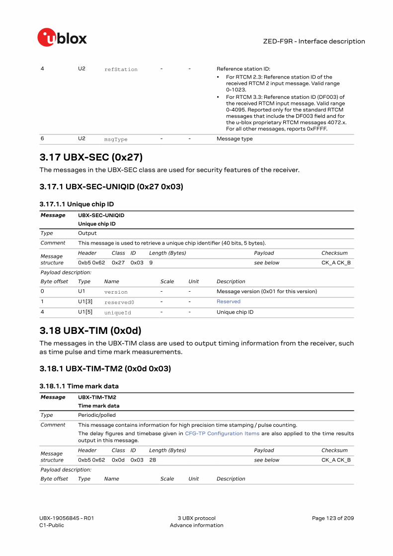
3.18.1 UBX-TIM-TM2 (0x0d 0x03)................................................................................................... 1233.18.1.1 Time mark data.............................................................................................................. 123
3.18.2 UBX-TIM-TP (0x0d 0x01).......................................................................................................1243.18.2.1 Time pulse time data.................................................................................................... 124
3.18.3 UBX-TIM-VRFY (0x0d 0x06)................................................................................................. 1253.18.3.1 Sourced time verification..............................................................................................125
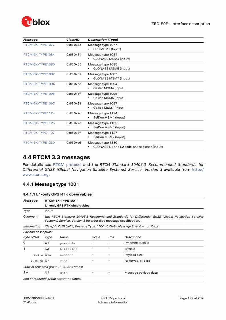
4.4.5 Message type 1005.................................................................................................................. 1314.4.5.1 Stationary RTK reference station ARP........................................................................ 131
4.4.6 Message type 1006.................................................................................................................. 1314.4.6.1 Stationary RTK reference station ARP with antenna height...................................131
4.4.7 Message type 1007.................................................................................................................. 1324.4.7.1 Antenna descriptor...........................................................................................................132
4.4.8 Message type 1009.................................................................................................................. 1324.4.8.1 L1-only GLONASS RTK observables.............................................................................132
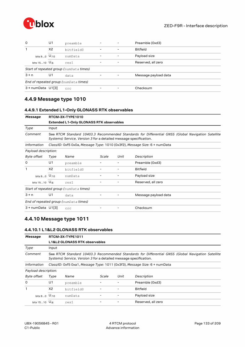
4.4.9 Message type 1010.................................................................................................................. 1334.4.9.1 Extended L1-Only GLONASS RTK observables..........................................................133
4.4.10 Message type 1011................................................................................................................ 1334.4.10.1 L1&L2 GLONASS RTK observables............................................................................133
4.4.12 Message type 1033................................................................................................................ 1344.4.12.1 Receiver and antenna descriptors.............................................................................. 134
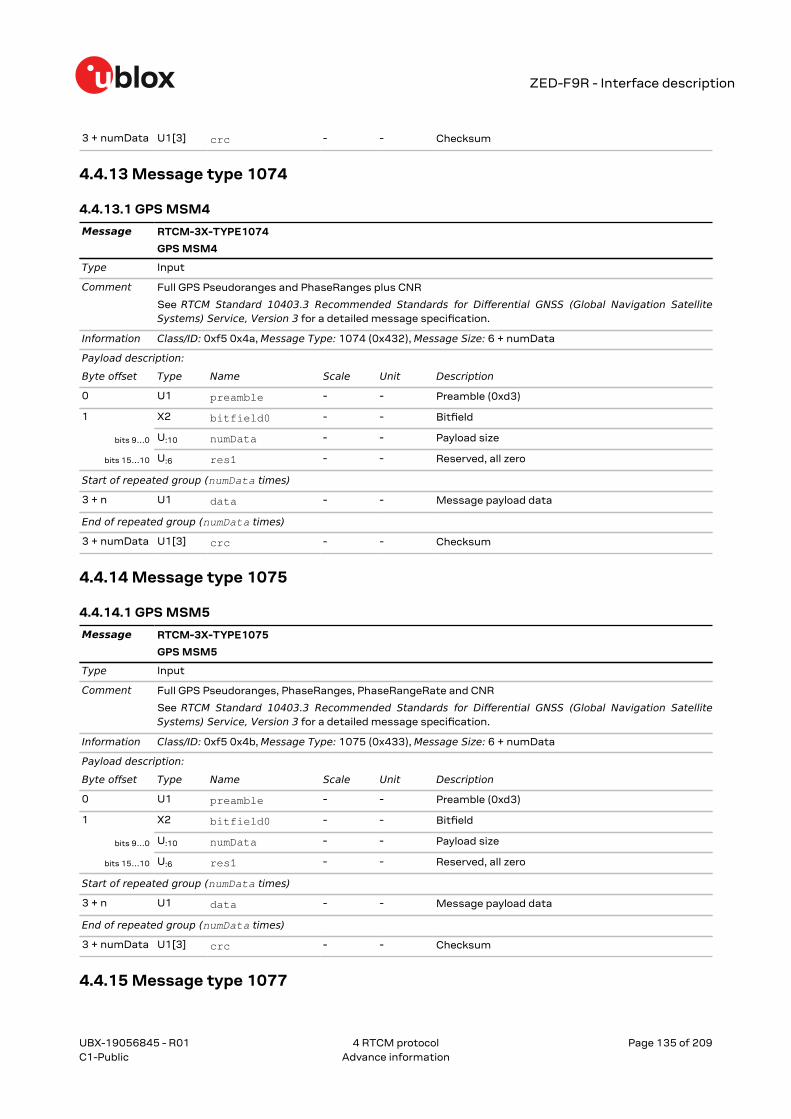
4.4.13 Message type 1074................................................................................................................ 1354.4.13.1 GPS MSM4.......................................................................................................................135
4.4.14 Message type 1075................................................................................................................ 1354.4.14.1 GPS MSM5.......................................................................................................................135
4.4.15 Message type 1077................................................................................................................ 1354.4.15.1 GPS MSM7.......................................................................................................................136
4.4.16 Message type 1084................................................................................................................ 1364.4.16.1 GLONASS MSM4............................................................................................................136
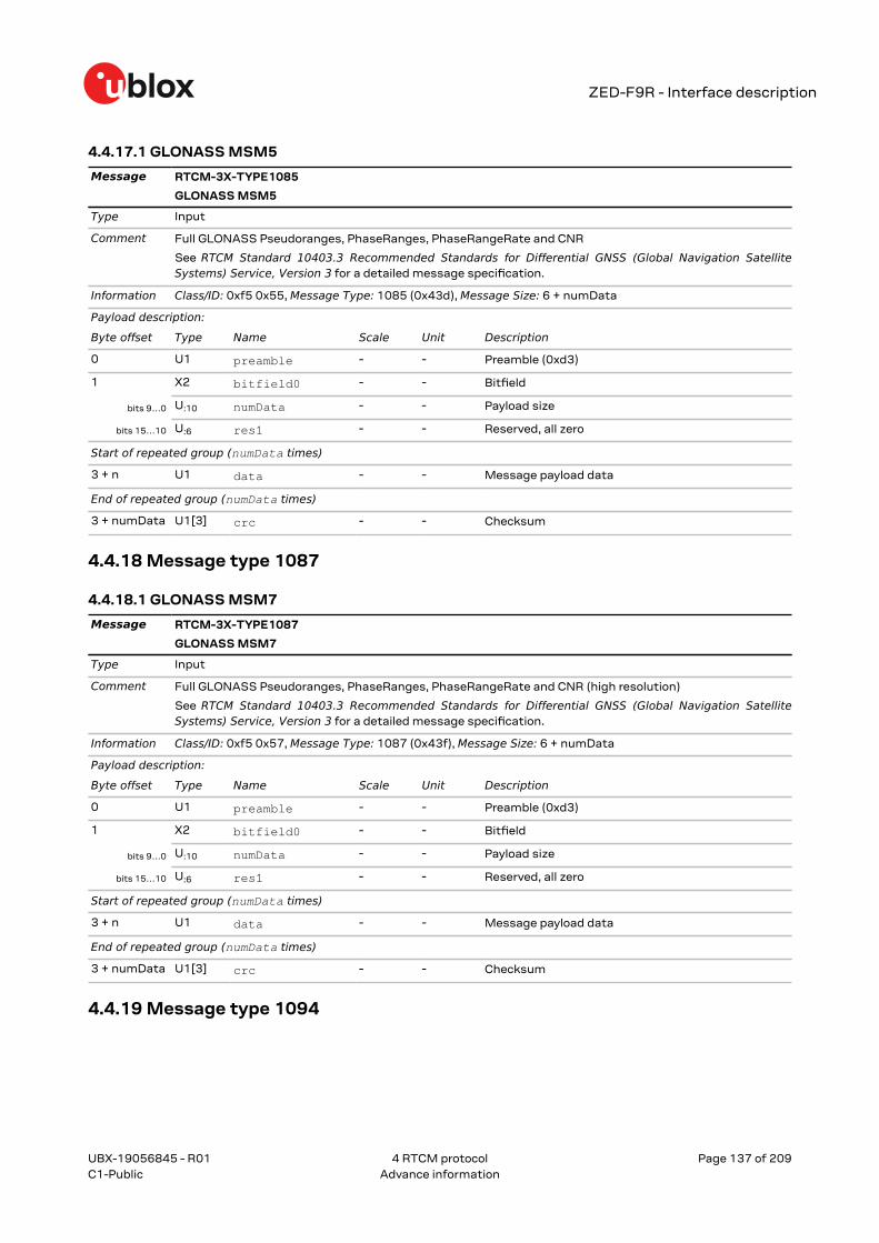
4.4.17 Message type 1085................................................................................................................ 1364.4.17.1 GLONASS MSM5............................................................................................................137
4.4.18 Message type 1087................................................................................................................ 1374.4.18.1 GLONASS MSM7............................................................................................................137
4.4.19 Message type 1094................................................................................................................ 1374.4.19.1 Galileo MSM4.................................................................................................................. 138
4.4.20 Message type 1095................................................................................................................ 1384.4.20.1 Galileo MSM5.................................................................................................................. 138
4.4.21 Message type 1097................................................................................................................ 1384.4.21.1 Galileo MSM7.................................................................................................................. 139
4.4.22 Message type 1124................................................................................................................ 1394.4.22.1 BeiDou MSM4..................................................................................................................139
4.4.23 Message type 1125................................................................................................................ 1394.4.23.1 BeiDou MSM5..................................................................................................................140
UBX-19056845 - R01
Contents Page 9 of 209C1-Public Advance information
ZED-F9R - Interface description
4.4.24 Message type 1127................................................................................................................ 1404.4.24.1 BeiDou MSM7..................................................................................................................140
4.4.25 Message type 1230................................................................................................................ 1404.4.25.1 GLONASS L1 and L2 code-phase biases.................................................................. 141
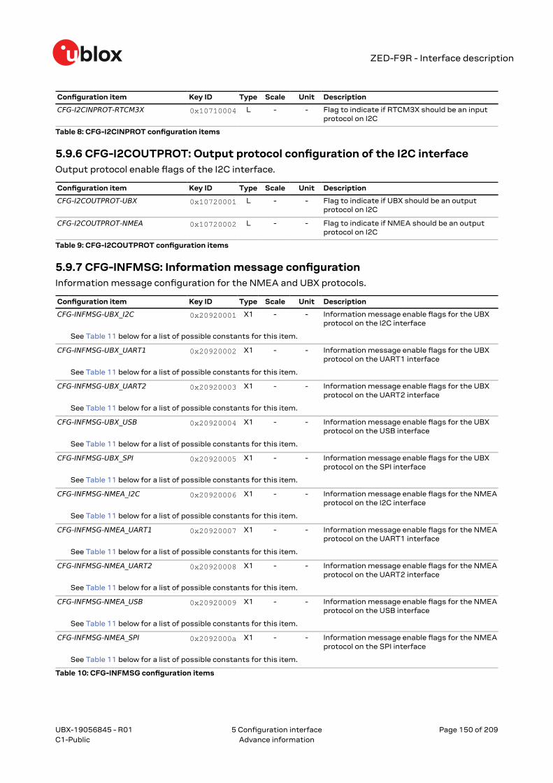
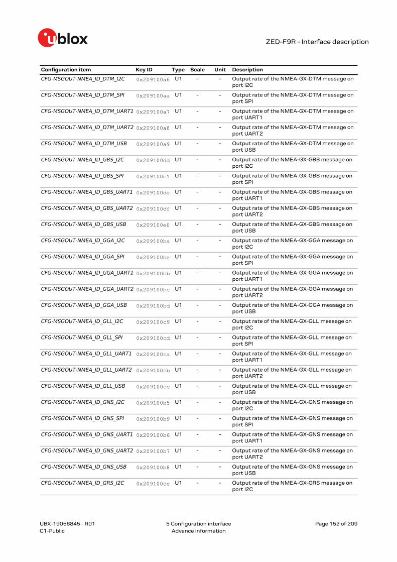
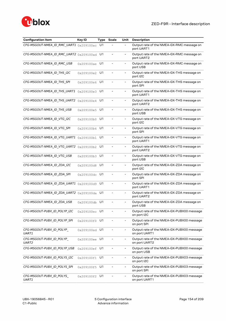
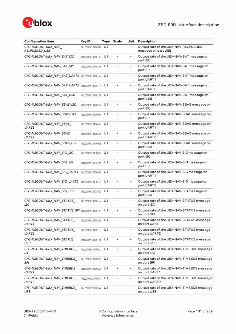
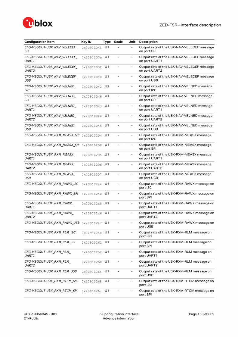
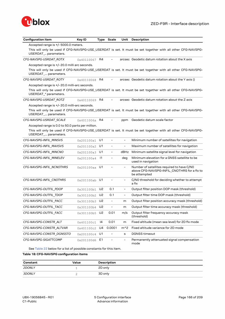
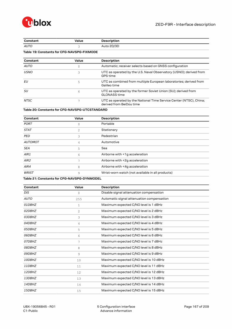
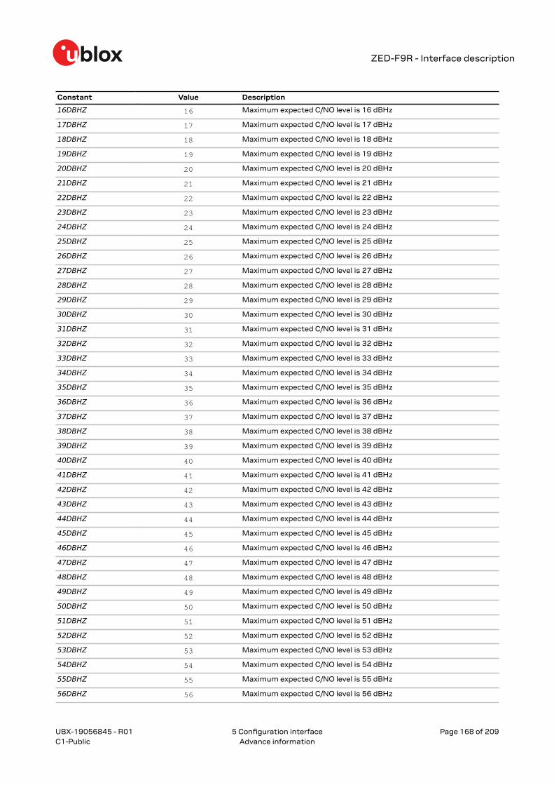
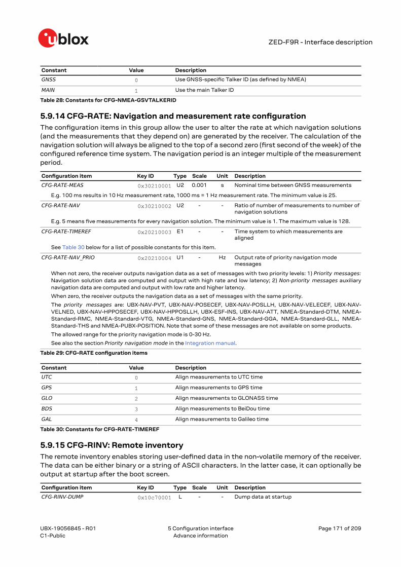
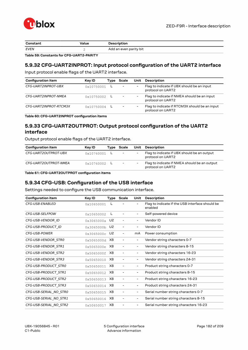
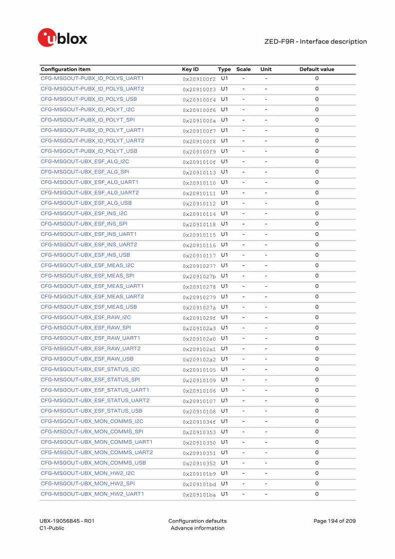
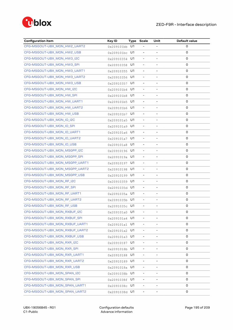
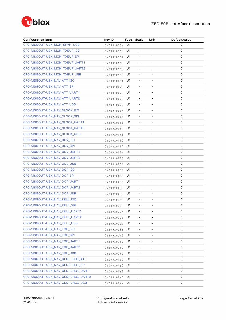
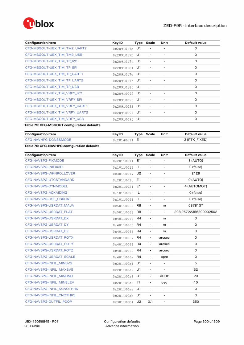
5.9.1 CFG-BDS: BeiDou system configuration.............................................................................. 1475.9.2 CFG-GEOFENCE: Geofencing configuration........................................................................ 1475.9.3 CFG-HW: Hardware configuration......................................................................................... 1485.9.4 CFG-I2C: Configuration of the I2C interface........................................................................1495.9.5 CFG-I2CINPROT: Input protocol configuration of the I2C interface................................1495.9.6 CFG-I2COUTPROT: Output protocol configuration of the I2C interface........................1505.9.7 CFG-INFMSG: Information message configuration........................................................... 1505.9.8 CFG-ITFM: Jamming and interference monitor configuration........................................ 1515.9.9 CFG-MOT: Motion detector configuration........................................................................... 1515.9.10 CFG-MSGOUT: Message output configuration................................................................ 1515.9.11 CFG-NAVHPG: High precision navigation configuration.................................................1645.9.12 CFG-NAVSPG: Standard precision navigation configuration.........................................1655.9.13 CFG-NMEA: NMEA protocol configuration........................................................................1695.9.14 CFG-RATE: Navigation and measurement rate configuration.......................................1715.9.15 CFG-RINV: Remote inventory............................................................................................... 1715.9.16 CFG-RTCM: RTCM protocol configuration.........................................................................1725.9.17 CFG-SBAS: SBAS configuration...........................................................................................1725.9.18 CFG-SEC: Security configuration.........................................................................................1745.9.19 CFG-SFCORE: Sensor fusion (SF) core configuration..................................................... 1745.9.20 CFG-SFIMU: Sensor fusion (SF) inertial measurement unit (IMU) configuration...... 1745.9.21 CFG-SFODO: Sensor fusion (SF) odometer configuration............................................. 1755.9.22 CFG-SIGNAL: Satellite systems (GNSS) signal configuration.......................................1765.9.23 CFG-SPI: Configuration of the SPI interface..................................................................... 1775.9.24 CFG-SPIINPROT: Input protocol configuration of the SPI interface............................. 1775.9.25 CFG-SPIOUTPROT: Output protocol configuration of the SPI interface..................... 1775.9.26 CFG-TP: Timepulse configuration....................................................................................... 1785.9.27 CFG-TXREADY: TX ready configuration............................................................................. 1795.9.28 CFG-UART1: Configuration of the UART1 interface........................................................1805.9.29 CFG-UART1INPROT: Input protocol configuration of the UART1 interface................1805.9.30 CFG-UART1OUTPROT: Output protocol configuration of the UART1 interface........1815.9.31 CFG-UART2: Configuration of the UART2 interface........................................................1815.9.32 CFG-UART2INPROT: Input protocol configuration of the UART2 interface................1825.9.33 CFG-UART2OUTPROT: Output protocol configuration of the UART2 interface........1825.9.34 CFG-USB: Configuration of the USB interface................................................................. 1825.9.35 CFG-USBINPROT: Input protocol configuration of the USB interface..........................183
UBX-19056845 - R01
Contents Page 10 of 209C1-Public Advance information
ZED-F9R - Interface description
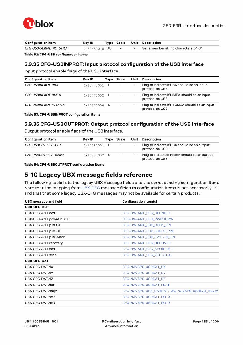
5.9.36 CFG-USBOUTPROT: Output protocol configuration of the USB interface..................1835.10 Legacy UBX message fields reference........................................................................................ 183
Contents Page 11 of 209C1-Public Advance information
ZED-F9R - Interface description
1 General information
1.1 Document overviewThis document describes the interface of the u-blox F9 high precision sensor fusion GNSS receiver.The interface consists of the following parts:
This document describes features that are common to many different u-blox GNSS andcorrection data receivers. Some of these features may not be available in ZED-F9R, andsome may require specific configurations to be enabled. See the Data sheet of your specificproduct for availability and the Integration manual for instructions for enabling the features.
Previous versions of u-blox receiver documentation combined general receiver descriptionand interface specification. In the current documentation the receiver description isincluded in the Integration manual.
1.2 Firmware and protocol versionsu-blox receivers execute firmware from internal ROM and from internal code-RAM. The firmwareimage is loaded into the code-RAM by a boot loader executed from ROM. The boot loader loads thefirmware into the code-RAM either from a connected flash memory or from the host processor.
The location and the version of the boot loader and the currently running firmware can be foundin the boot screen and in the UBX-MON-VER message. If the firmware has been loaded from aconnected flash or from the host processor, it is indicated by text "EXT". When the receiver is started,the boot screen is output automatically in UBX-INF-NOTICE or NMEA-Standard-TXT messages ifconfigured using CFG-INFMSG. The UBX-MON-VER message can be polled using the UBX pollingmechanism.
The following u-center screenshots show an example of a u-blox receiver running firmware loadedfrom flash:
UBX-19056845 - R01
1 General information Page 12 of 209C1-Public Advance information
ZED-F9R - Interface description
The following information is available (✓) from the boot screen (B) and the UBX-MON-VER message(M):
B M Example Information
✓ u-blox AG - www.u-blox.com Start of the boot screen.
✓ HW UBX 9 00190000 Hardware version of the u-blox receiver.
✓ 00190000
✓ ✓ EXT CORE 1.00 (61b2dd) Base (CORE) firmware version and revision number, loaded from externalmemory (EXT).
EXT LAP 1.00 (12a3bc) Product firmware version and revision number, loaded from external memory(EXT). Available only in some firmware versions. See below for a list of productacronyms.
✓ ✓ ROM BASE 0x118B2060 Revision number of the underlying boot loader firmware in ROM.
✓ ✓ FWVER=HPG 1.12 Product firmware version number, where:
• SPG = Standard precision GNSS product• HPG = High precision GNSS product• ADR = Dead reckoning product• TIM = Time sync product• LAP = Lane accurate positioning product• HPS = High precision sensor fusion product
✓ ✓ PROTVER=27.11 Supported protocol version.
✓ ✓ MOD=ZED-F9P Module name (if available).
✓ ✓ GPS;GLO;GAL;BDS List of supported major GNSS (see GNSS identifiers).
✓ ✓ SBAS;QZSS List of supported augmentation systems (see GNSS identifiers).
✓ ANTSUPERV=AC SD PDoS SR Configuration of the antenna supervisor (if available), where:
• AC = Active antenna control enabled• SD = Short circuit detection enabled• OD = Open circuit detection enabled• PDoS = Short circuit power down logic enabled• SR = Automatic recovery from short state enabled
✓ PF=FFF79 Product configuration.
The "FWVER" product firmware version indicates which firmware is currently running. Thisis referred to as "firmware version" in this and other documents.
The revision numbers should only be used to identify a known firmware version. They arenot necessarily numeric nor are they guaranteed to increase with newer firmware versions.
Similarly, firmware version numbers can have additional non-numeric informationappended, such as in "1.00B03".
Not every entry is output by all u-blox receivers. The availability of some of the informationdepends on the product, the firmware location and the firmware version.
The product firmware version and the base firmware version relate to the protocol version:
Product firmware version Base firmware version Protocol version
HPS 1.00 EXT CORE 1.00 (500086) 33.00
HPS 1.20 EXT CORE 1.00 (a669b8) 33.20
UBX-19056845 - R01
1 General information Page 13 of 209C1-Public Advance information
ZED-F9R - Interface description
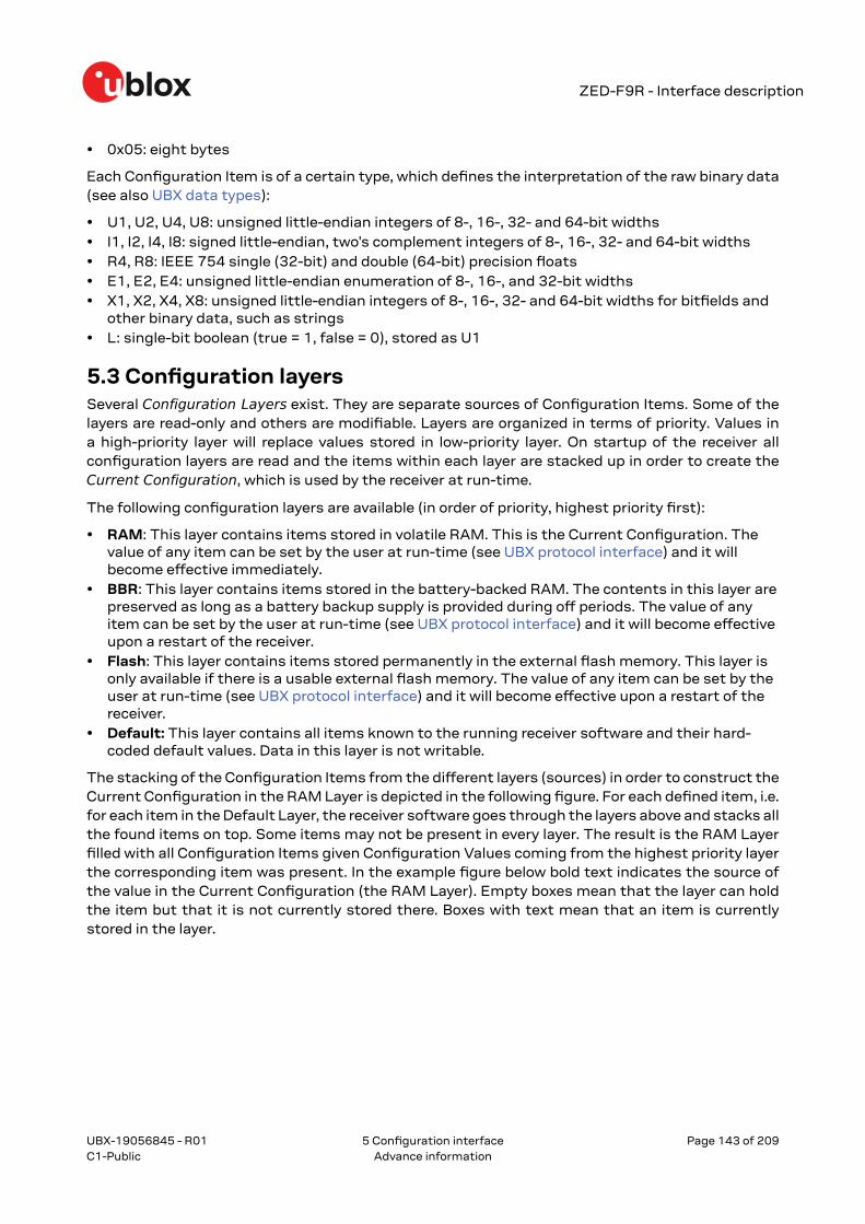
1.3 Receiver configurationu-blox positioning receivers are fully configurable with UBX protocol messages. The configurationused by the receiver during normal operation is called the "current configuration". The currentconfiguration can be changed during normal operation by sending UBX-CFG-VALSET messagesover any I/O port. The receiver will change its current configuration immediately after receiving aconfiguration message. The receiver will always use the current configuration only.
The current configuration is loaded from permanent configuration hard-coded in the receiverfirmware (the defaults) and from non-volatile memory (user configuration) on startup of the receiver.Changes made to the current configuration at run-time will be lost when there is a power cycle, ahardware reset or a (complete) controlled software reset (see Configuration reset behavior).
See Configuration interface for a detailed description of the receiver configuration system, theexplanation of the configuration concept and its principles and interfaces.
The configuration interface has changed from earlier u-blox positioning receivers. Thereis some backwards compatibility provided in UBX-CFG configuration messages. Users arestrongly advised to only use the Configuration interface. See also Legacy UBX messagefields reference.
See the Integration manual for a basic receiver configuration most commonly used.
1.4 NamingMessage names are written in full with the parts of the name separated by hyphens ("-"). The fullmessage name consists of the protocol name (e.g., UBX), the class name (e.g. NAV) and the messagename (e.g. PVT). For example the receiver software version information message is referred to asUBX-MON-VER. Similarly, the NMEA-Standard-GGA is the NMEA standard message (sentence) withthe global positioning fix data.
References to fields of the message add the field name separated by a dot ("."), e.g. UBX-MON-VER.swVersion.
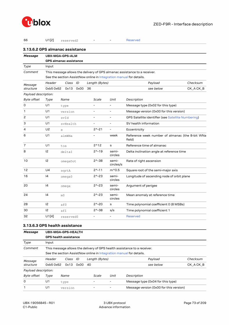
Some messages use a fourth level of naming, called the message version. One example is the UBX-MGA-GPS message for GPS assistance data, which exists in versions for ephemerides (UBX-MGA-GPS-EPH) and almanacs (UBX-MGA-GPS-ALM).
Names of configuration items are of the form CFG-GROUP-ITEM. For example, CFG-NAVSPG-DYNMODEL refers to the navigation dynamic platform model the receiver uses. Constants adda fourth level to the item name, such as CFG-NAVSPG-DYNMODEL-AUTOMOT for the automotiveplatform model. In the context of describing an item's value, only the last part of the constant namecan be used (e.g. "set CFG-NAVSPG-DYNMODEL to PORT for portable applications").
1.5 GNSS, satellite and signal identifiers
1.5.1 OverviewThe UBX protocol messages use two different numbering schemes. Some messages use a one-byte
(type U1) field for the satellite identifier (normally named svid). This uses numbering similar to the"extended" NMEA scheme and is merely an extension of the scheme in use for previous generationsof u-blox receivers.
With the ever increasing numbers of GNSS satellites, this scheme has been phased out inrecent u-blox positioning receivers (as numbers greater than 255 would have become necessary).Consequently, newer messages use a more sophisticated, flexible and future-proof approach. This
UBX-19056845 - R01
1 General information Page 14 of 209C1-Public Advance information
ZED-F9R - Interface description
involves having a separate gnssId field to identify which GNSS the satellite is part of and a simple
svId (SV for space vehicle) field that indicates which number the satellite is in that system. In nearlyall cases, this means that the svId is the natural number associated with the satellite. For examplethe GLONASS SV4 is identified as gnssId 6, svId 4, while the GPS SV4 is gnssId 0, svId 4.
Signal identifiers are used where different signals from a GNSS satellite need to be distinguished
(e.g. in the UBX-NAV-SIG message). A separate sigId field is used. These identifiers are only valid
when combined with a GNSS identifier (gnssId field).
The NMEA protocol (version 4.10 and later) identifies GNSS satellites with a one-digit system IDand a two-digit satellite number. u-blox receivers support this method in their NMEA output when"strict" SV numbering is selected. In most cases this is the default setting, but it can be checked orchanged using the Configuration interface (see also NMEA GNSS, satellite and signal numbering).
In order to support some GNSS (e.g. BeiDou, Galileo, QZSS), which are not supported by some orall NMEA protocol versions, an "extended" SV numbering scheme can be enabled. This uses theNMEA-defined numbers where possible but adds other number ranges to support other GNSS. Notehowever that these non-standard extensions require 3-digit numbers, which may not be supportedby some NMEA parsing software. For example, QZSS satellites use numbers in the range 193 to 202.
The NMEA standard defines signal identifiers to distinguish different signals sent by a singleGNSS satellite (e.g. L2 CL and CM). u-blox positioning receivers use those identifiers for signalidentification, as far as the corresponding standard is supported in a particular product.
Note that the following sections are a generic overview for different u-blox positioningreceivers. A particular product may not support all of the described GNSS identifiers,satellite numbers, signal identifiers or combinations thereof.
1.5.2 GNSS identifiersThe following table lists each GNSS along with the GNSS identifiers (UBX protocol), the system IDs(NMEA protocol), and abbreviations used in this document:
GNSS Abbreviations UBX gnssId NMEA system ID
2.3 - 4.0 4.10 4.11
GPS GPS G 0 1 1 1
SBAS SBAS S 1 1 1 1
Galileo GAL E 2 n/a 3 3
BeiDou BDS B 3 n/a (4)1 4
IMES IMES I 4 n/a n/a n/a
QZSS QZSS Q 5 n/a (1)1 5
GLONASS GLO R 6 2 2 2
Other values will be added when support for other GNSS types will be enabled in u-blox receivers.
See also NMEA Talker ID.
1.5.3 Satellite identifiersA summary of all the satellite numbering schemes used in the NMEA protocol and the UBX protocolis provided in the following table.
1 While not defined by NMEA 4.10, u-blox receivers in this mode will use system ID 4 for BeiDou and, if extended satellitenumbering is enabled, system ID 1 for QZSS.
UBX-19056845 - R01
1 General information Page 15 of 209C1-Public Advance information
ZED-F9R - Interface description
UBX Protocol NMEA Protocol2.3 - 4.0
NMEA Protocol 4.10 NMEA Protocol 4.11
GNSS SV Range gnssId:svId single svId (strict) (extended) (strict) (extended) (strict) (extended)
Note that GLONASS satellites can be tracked before they have been identified. In UBX messagessuch unknown satellites will be reported with svId 255. In NMEA messages they will be null (empty)fields. Product-related documentation and u-center will use R? to label unidentified GLONASSsatellites.
1.5.4 Signal identifiersA summary of all the signal identification schemes used in the NMEA protocol and the UBX protocolis provided in the following table.
Signal gnssId sigId System ID Signal ID System ID Signal ID
GPS L1C/A2 0 0 1 1 1 1
GPS L2 CL 0 3 1 6 1 6
GPS L2 CM 0 4 1 5 1 5
GPS L5 I 0 6 1 7 1 7
GPS L5 Q 0 7 1 8 1 8
SBAS L1C/A2 1 0 1 1 1 1
Galileo E1 C2 2 0 3 7 3 7
Galileo E1 B2 2 1 3 7 3 7
Galileo E5 aI 2 3 3 1 3 1
Galileo E5 aQ 2 4 3 1 3 1
Galileo E5 bI 2 5 3 2 3 2
Galileo E5 bQ 2 6 3 2 3 2
BeiDou B1I D12 3 0 (4)3 (1)4 4 1
BeiDou B1I D22 3 1 (4)3 (1)4 4 1
BeiDou B2I D1 3 2 (4)3 (3)4 4 B
BeiDou B2I D2 3 3 (4)3 (3)4 4 B
2 UBX messages that do not have an explicit sigId field contain information about the subset of signals marked.3 While not defined by NMEA 4.10, u-blox receivers in this mode will use system ID 4 for BeiDou and, if extended satellite
numbering is enabled, system ID 1 for QZSS.4 BeiDou and QZSS signal ID are not defined in the NMEA protocol version 4.10. Values shown in the table are only valid for
u-blox products and, for QZSS signal ID, if extended satellite numbering is enabled.5 NMEA System ID and Signal ID are in hexadecimal format.
UBX-19056845 - R01
1 General information Page 16 of 209C1-Public Advance information
Signal gnssId sigId System ID Signal ID System ID Signal ID
BeiDou B2 A 3 7 (4)3 N/A 4 5
QZSS L1C/A2 5 0 (1)3 (1)4 5 1
QZSS L1S 5 1 (1)3 (4)4 5 4
QZSS L2 CM 5 4 (1)3 (5)4 5 5
QZSS L2 CL 5 5 (1)3 (6)4 5 6
QZSS L5 I 5 8 (1)3 N/A 5 7
QZSS L5 Q 5 9 (1)3 N/A 5 8
GLONASS L1 OF2 6 0 2 1 2 1
GLONASS L2 OF 6 2 2 3 2 3
1.6 Message typesThe following message types are defined:
Message type Description
Input Messages that are input to the receiver and never output. E.g. UBX-MGA-GPS-EPH.
Output Messages that are output by the receiver in no particular interval and never input. E.g. UBX-ACK-ACK.
Input/output Messages that can be output by or input to the receiver. E.g. UBX-MGA-DBD-DATA0.
Periodic Messages that are output in regular intervals but cannot be polled. E.g. UBX-NAV-EOE.
Periodic/polled Messages that are output in regular intervals and can be polled. E.g. UBX-NAV-PVT.
Command Messages that are a command to the receiver. Similar to type Input these are input-only. E.g.UBX-CFG-RST.
Get Output-only configuration or command messages. E.g. UBX-CFG-DAT.
Set Input-only configuration or command messages. E.g. UBX-CFG-VALDEL.
Get/set Input/output configuration or command messages. E.g. UBX-CFG-NAVX5.
Polled Non-periodic messages that can only be polled. E.g. UBX-MON-VER.
Poll request Poll request. E.g. UBX-MGA-DBD-POLL.
UBX-19056845 - R01
1 General information Page 17 of 209C1-Public Advance information
ZED-F9R - Interface description
2 NMEA protocolThe following sections give an overview of the NMEA messages used by u-blox positioning receivers.
By default, the NMEA messages sent by u-blox positioning receivers are based on the NMEA 0183version 4.11 standard. For further information on the NMEA standard, refer to the NMEA 0183Standard for Interfacing Marine Electronic Devices, Version 4.11, November 2018, which is availableon http://www.nmea.org/.
2.1 NMEA frame structureThe following figure shows the structure of a NMEA protocol message (called "sentences" in thestandard).
2.2 NMEA protocol configurationThe NMEA protocol on u-blox receivers can be configured for customer applications by using theConfiguration interface (CFG-NMEA-* items).
There are five NMEA standards supported. The default NMEA version is 4.11. Alternatively versions4.10, 4.00, 2.3, or 2.1 can be configured. See CFG-NMEA-PROTVER to configure the version. SeeNMEA multi-GNSS operation and NMEA data fields for details on how this affects the output.
The following filtering flags can be used to configure the output of some NMEA message fields:
Filter Configuration Item Description
Position filtering CFG-NMEA-OUT_INVFIX Enable to permit positions from failed or invalid fixes to bereported (with the "V" status flag to indicate that the data is notvalid).
Valid position filtering CFG-NMEA-OUT_MSKFIX Enable to permit positions from invalid fixes to be reported (withthe "V" status flag to indicate that the data is not valid).
Time filtering CFG-NMEA-OUT_INVTIME Enable to permit the receiver's best knowledge of time to beoutput, even though it might be wrong.
Date filtering CFG-NMEA-OUT_INVDATE Enable to permit the receiver's best knowledge of date to beoutput, even though it might be wrong.
UBX-19056845 - R01
2 NMEA protocol Page 18 of 209C1-Public Advance information
GPS-only filtering CFG-NMEA-OUT_ONLYGPS Enable to restrict output to only report GPS satellites.
Track filtering CFG-NMEA-OUT_FROZENCOG Enable to permit course over ground (COG) to be reported evenwhen it would otherwise be frozen.
The following filtering flags can be used to configure the output of some NMEA message flags:
Mode Configuration Item Description
Compatibility mode CFG-NMEA-COMPAT Some older NMEA applications expect the NMEA output to beformatted in a specific way, for example, they will only work if thelatitude and longitude have exactly four digits behind the decimalpoint. u-blox receivers offer a compatibility mode to support theselegacy applications.
Consideration mode CFG-NMEA-CONSIDER u-blox receivers use a sophisticated signal quality detectionscheme, in order to produce the best possible position output.This algorithm considers all SV measurements, and mayeventually decide to only use a subset thereof, if it improvesthe overall position accuracy. If consideration mode is enabled,all satellites, which were considered for navigation, arecommunicated as being used for the position determination.If consideration mode is disabled, only those satellites whichafter the consideration step remained in the position output aremarked as being used.
Limit length mode CFG-NMEA-LIMIT82 Enabling this mode will limit the NMEA sentence length to amaximum of 82 characters.
High precision mode CFG-NMEA-HIGHPREC Enabling this mode increases precision of the position output.Latitude and longitude then have seven digits after the decimalpoint, and altitude has three digits after the decimal point. Note:The high precision mode cannot be set in conjunction with eithercompatibility mode or Limit82 mode.
The following extended configuration options are available:
Option Configuration Item(s) Description
GNSS to filter CFG-NMEA-FILT_GPS etc. Filters satellites based on the GNSS they belong to.
Satellite numbering CFG-NMEA-SVNUMBERING This field configures the display of satellites that do not have anNMEA-defined value. Note: this does not apply to satellites withan unknown ID. See also Satellite identifiers.
Main Talker ID CFG-NMEA-MAINTALKERID By default the main Talker ID (i.e. the Talker ID used for allmessages other than GSV) is determined by the GNSSassignment of the receiver's channels (see configuration itemsCFG-SIGNAL-*). This field enables the main Talker ID to beoverridden. See also NMEA Talker ID.
GSV Talker ID CFG-NMEA-GSVTALKERID By default the Talker ID for GSV messages is GNSS-specific (asdefined by NMEA). This field enables the GSV Talker ID to beoverridden.
BDS Talker ID CFG-NMEA-BDSTALKERID By default the Talker ID for BeiDou is "GB". This field enables theBeiDou Talker ID to be overridden.
2.3 NMEA-proprietary messagesThe NMEA standard allows for proprietary, manufacturer-specific messages to be added. Theseshall be marked with a manufacturer mnemonic. The mnemonic assigned to u-blox is UBX and isused for all non-standard messages. These proprietary NMEA messages therefore have the addressfield set to PUBX. The first data field in a PUBX message identifies the message number with twodigits.
UBX-19056845 - R01
2 NMEA protocol Page 19 of 209C1-Public Advance information
ZED-F9R - Interface description
2.4 NMEA multi-GNSS operationMany applications that process NMEA messages assume that only a single GNSS is active.However, when multiple GNSS are configured, the NMEA specification requires the output to changein the following ways:
Main Talker ID The main NMEA Talker ID will be "GN" (e.g. instead of "GP" for a GPS-only receiver).
GSV Talker IDs The GSV message reports the signal strength of the visible satellites. However, theTalker ID it uses is specific to the GNSS it is reporting information for, so for a multi-GNSS receiverit will not be the same as the main Talker ID. While other messages use the "GN" Talker ID, the GSVmessage will use GNSS-specific Talker IDs. See also NMEA protocol configuration.
Multiple GSA and GRS messages Multiple GSA and GRS messages are output for each fix, one foreach GNSS. This may confuse applications that assume they are output only once per position fix(as is the case for a single GNSS receiver).
GGA Talker IDs The NMEA specification indicates that the GGA message is GPS-specific. However,u-blox receivers support the output of a GGA message for each of the Talker IDs.
BeiDou and Galileo Only NMEA version 4.10 and later have support for these systems.
QZSS Only NMEA version 4.11 and later have support for this system.
Extended satellite numbering In order to support some GNSS (e.g. BeiDou, Galileo, QZSS) that arenot supported by some or all NMEA protocol versions, an "extended" SV numbering scheme can beenabled. This uses the NMEA-defined numbers where possible, but adds other number ranges tosupport other GNSS. Note however that these non-standard extensions require 3-digit numbers,which may not be supported by some NMEA parsing software. For example, QZSS satellites usenumbers in the range 193 to 202. See NMEA protocol configuration and Satellite identifiers.
2.5 NMEA data fieldsVarious data fields in NMEA messages depend on NMEA protocol configuration or require adefinition for their interpretation.
2.5.1 NMEA Talker IDOne of the ways the NMEA standard differs depending on the GNSS is by using a two-letter messageidentifier, the "Talker ID". The specific Talker ID used by a u-blox receiver will depend on the productand its configuration. The table below shows the Talker ID that will be used for various GNSSconfigurations by default.
GNSS Talker ID Comments
GPS, SBAS GP NMEA 2.3+
GLONASS GL NMEA 2.3+
Galileo GA NMEA 4.10+
BeiDou GB NMEA 4.10+ (official NMEA only since 4.11)
QZSS GQ NMEA 4.11+ (GP for NMEA 2.3 - 4.10)
Any combination of GNSS GN
2.5.2 NMEA extra fieldsThe following extra fields are available in NMEA 4.10 and later.
UBX-19056845 - R01
2 NMEA protocol Page 20 of 209C1-Public Advance information
ZED-F9R - Interface description
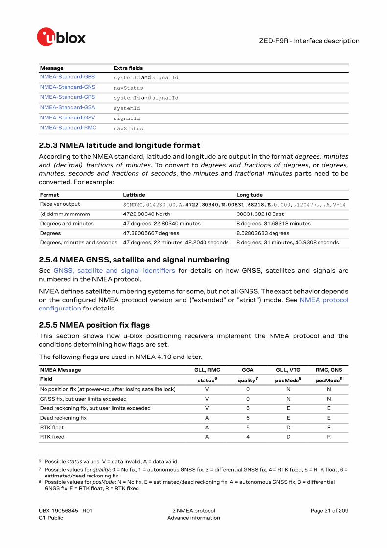
Message Extra fields
NMEA-Standard-GBS systemId and signalId
NMEA-Standard-GNS navStatus
NMEA-Standard-GRS systemId and signalId
NMEA-Standard-GSA systemId
NMEA-Standard-GSV signalId
NMEA-Standard-RMC navStatus
2.5.3 NMEA latitude and longitude formatAccording to the NMEA standard, latitude and longitude are output in the format degrees, minutesand (decimal) fractions of minutes. To convert to degrees and fractions of degrees, or degrees,minutes, seconds and fractions of seconds, the minutes and fractional minutes parts need to beconverted. For example:
2.5.4 NMEA GNSS, satellite and signal numberingSee GNSS, satellite and signal identifiers for details on how GNSS, satellites and signals arenumbered in the NMEA protocol.
NMEA defines satellite numbering systems for some, but not all GNSS. The exact behavior dependson the configured NMEA protocol version and ("extended" or "strict") mode. See NMEA protocolconfiguration for details.
2.5.5 NMEA position fix flagsThis section shows how u-blox positioning receivers implement the NMEA protocol and theconditions determining how flags are set.
The following flags are used in NMEA 4.10 and later.
NMEA Message GLL, RMC GGA GLL, VTG RMC, GNS
Field status6 quality7 posMode8 posMode8
No position fix (at power-up, after losing satellite lock) V 0 N N
GNSS fix, but user limits exceeded V 0 N N
Dead reckoning fix, but user limits exceeded V 6 E E
Dead reckoning fix A 6 E E
RTK float A 5 D F
RTK fixed A 4 D R
6 Possible status values: V = data invalid, A = data valid7 Possible values for quality: 0 = No fix, 1 = autonomous GNSS fix, 2 = differential GNSS fix, 4 = RTK fixed, 5 = RTK float, 6 =
estimated/dead reckoning fix8 Possible values for posMode: N = No fix, E = estimated/dead reckoning fix, A = autonomous GNSS fix, D = differential
GNSS fix, F = RTK float, R = RTK fixed
UBX-19056845 - R01
2 NMEA protocol Page 21 of 209C1-Public Advance information
ZED-F9R - Interface description
NMEA Message GLL, RMC GGA GLL, VTG RMC, GNS
Field status6 quality7 posMode8 posMode8
2D GNSS fix A 1 / 2 A / D A / D
3D GNSS fix A 1 / 2 A / D A / D
Combined GNSS/dead reckoning fix A 1 / 2 A / D A / D
In high precision GNSS (HPG) products it is recommended to select NMEA version 4.10 or above.Earlier versions do not support the float RTK (F) and real time kinematic (R) mode indicator flagsin all messages.
The following flags are used in NMEA 2.3 - 4.0.
NMEA Message GLL, RMC GGA GSA GLL, VTG,RMC, GNS
Field status9 quality10 navMode11 posMode12
No position fix (at power-up, after losing satellite lock) V 0 1 N
GNSS fix, but user limits exceeded V 0 1 N
Dead reckoning fix, but user limits exceeded V 6 2 E
Dead reckoning fix A 6 2 E
2D GNSS fix A 1 / 2 2 A / D
3D GNSS fix A 1 / 2 3 A / D
Combined GNSS/dead reckoning fix A 1 / 2 3 A / D
The flags in NMEA 2.1 and earlier are the same as NMEA 2.3 but with the following differences:
• The posMode field is not output for GLL, RMC and VTG messages (each message has one fieldless).
• The GGA quality field is set to 1 (instead of 6) for both types of dead reckoning fix.
2.5.6 NMEA output of invalid or unknown dataBy default the receiver will not output invalid data. In such cases, it will output empty fields. SeeNMEA protocol configuration for options to adjust this behavior.
An invalid position fix (but valid time) is reported as follows:
$GPGLL,,,,,124924.00,V,N*42
If the time is unknown (e.g. during a cold start):
$GPGLL,,,,,,V,N*64
Unlike the NMEA standard behavior to invalid data, dead reckoning products always reporta position. It is marked as invalid (V) when the user limits are exceeded or valid (A) if the userlimits are met.
9 Possible values for status: V = data invalid, A = data valid10 Possible values for quality: 0 = no fix, 1 = autonomous GNSS fix, 2 = differential GNSS fix, 4 = RTK fixed, 5 = RTK float, 6 =
estimated/dead reckoning fix11 Possible values for navMode: 1 = No fix, 2 = 2D fix, 3 = 3D fix12 Possible values for posMode: N = No fix, E = estimated/dead reckoning fix, A = autonomous GNSS fix, D = differential
GNSS fix
UBX-19056845 - R01
2 NMEA protocol Page 22 of 209C1-Public Advance information
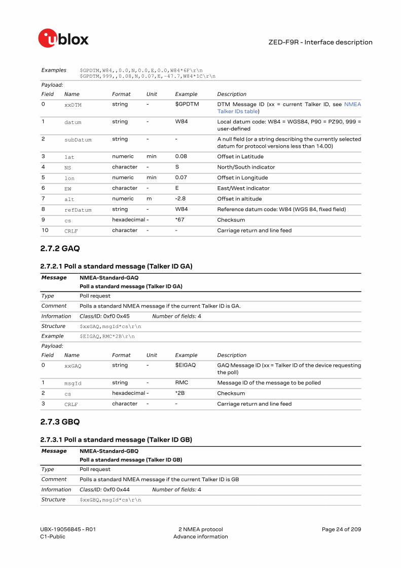
10 CRLF character - - Carriage return and line feed
2.7.2 GAQ
2.7.2.1 Poll a standard message (Talker ID GA)
Message NMEA-Standard-GAQ
Poll a standard message (Talker ID GA)
Type Poll request
Comment Polls a standard NMEA message if the current Talker ID is GA.
Information Class/ID: 0xf0 0x45 Number of fields: 4
Structure $xxGAQ,msgId*cs\r\n
Example $EIGAQ,RMC*2B\r\n
Payload:
Field Name Format Unit Example Description
0 xxGAQ string - $EIGAQ GAQ Message ID (xx = Talker ID of the device requestingthe poll)
1 msgId string - RMC Message ID of the message to be polled
2 cs hexadecimal - *2B Checksum
3 CRLF character - - Carriage return and line feed
2.7.3 GBQ
2.7.3.1 Poll a standard message (Talker ID GB)
Message NMEA-Standard-GBQ
Poll a standard message (Talker ID GB)
Type Poll request
Comment Polls a standard NMEA message if the current Talker ID is GB
Information Class/ID: 0xf0 0x44 Number of fields: 4
Structure $xxGBQ,msgId*cs\r\n
UBX-19056845 - R01
2 NMEA protocol Page 24 of 209C1-Public Advance information
ZED-F9R - Interface description
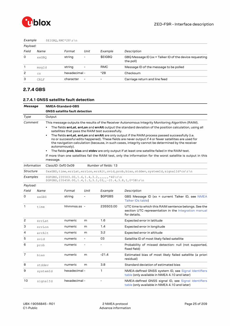
Example $EIGBQ,RMC*28\r\n
Payload:
Field Name Format Unit Example Description
0 xxGBQ string - $EIGBQ GBQ Message ID (xx = Talker ID of the device requestingthe poll)
1 msgId string - RMC Message ID of the message to be polled
2 cs hexadecimal - *28 Checksum
3 CRLF character - - Carriage return and line feed
2.7.4 GBS
2.7.4.1 GNSS satellite fault detection
Message NMEA-Standard-GBS
GNSS satellite fault detection
Type Output
Comment This message outputs the results of the Receiver Autonomous Integrity Monitoring Algorithm (RAIM).
• The fields errLat, errLon and errAlt output the standard deviation of the position calculation, using allsatellites that pass the RAIM test successfully.
• The fields errLat, errLon and errAlt are only output if the RAIM process passed successfully (i.e.no or successful edits happened). These fields are never output if 4 or fewer satellites are used forthe navigation calculation (because, in such cases, integrity cannot be determined by the receiverautonomously).
• The fields prob, bias and stdev are only output if at least one satellite failed in the RAIM test.
If more than one satellites fail the RAIM test, only the information for the worst satellite is output in thismessage.
Information Class/ID: 0xf0 0x09 Number of fields: 13
0 xxGBS string - $GPGBS GBS Message ID (xx = current Talker ID, see NMEATalker IDs table)
1 time hhmmss.ss - 235503.00 UTC time to which this RAIM sentence belongs. See thesection UTC representation in the Integration manualfor details.
2 errLat numeric m 1.6 Expected error in latitude
3 errLon numeric m 1.4 Expected error in longitude
4 errAlt numeric m 3.2 Expected error in altitude
5 svid numeric - 03 Satellite ID of most likely failed satellite
6 prob numeric - - Probability of missed detection: null (not supported,fixed field)
7 bias numeric m -21.4 Estimated bias of most likely failed satellite (a prioriresidual)
8 stddev numeric m 3.8 Standard deviation of estimated bias
9 systemId hexadecimal - 1 NMEA-defined GNSS system ID, see Signal Identifierstable (only available in NMEA 4.10 and later)
10 signalId hexadecimal - - NMEA-defined GNSS signal ID, see Signal Identifierstable (only available in NMEA 4.10 and later)
UBX-19056845 - R01
2 NMEA protocol Page 25 of 209C1-Public Advance information
ZED-F9R - Interface description
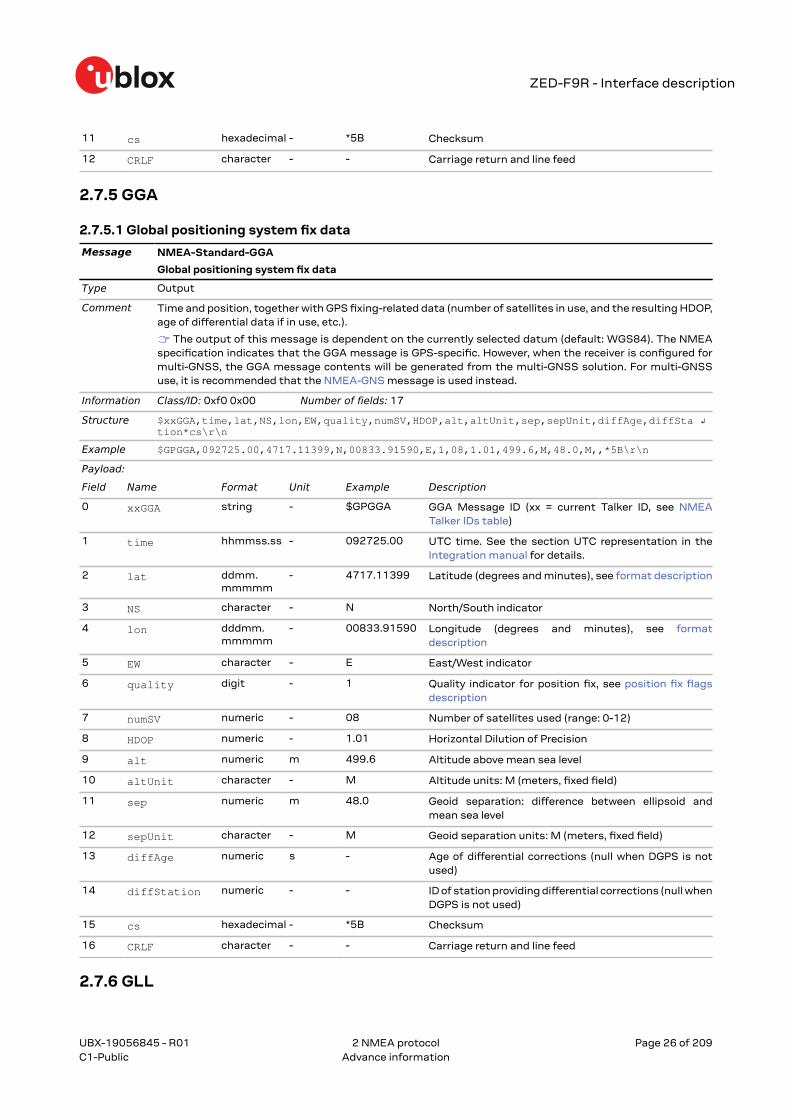
11 cs hexadecimal - *5B Checksum
12 CRLF character - - Carriage return and line feed
2.7.5 GGA
2.7.5.1 Global positioning system fix data
Message NMEA-Standard-GGA
Global positioning system fix data
Type Output
Comment Time and position, together with GPS fixing-related data (number of satellites in use, and the resulting HDOP,age of differential data if in use, etc.).
☞ The output of this message is dependent on the currently selected datum (default: WGS84). The NMEAspecification indicates that the GGA message is GPS-specific. However, when the receiver is configured formulti-GNSS, the GGA message contents will be generated from the multi-GNSS solution. For multi-GNSSuse, it is recommended that the NMEA-GNS message is used instead.
Information Class/ID: 0xf0 0x00 Number of fields: 17
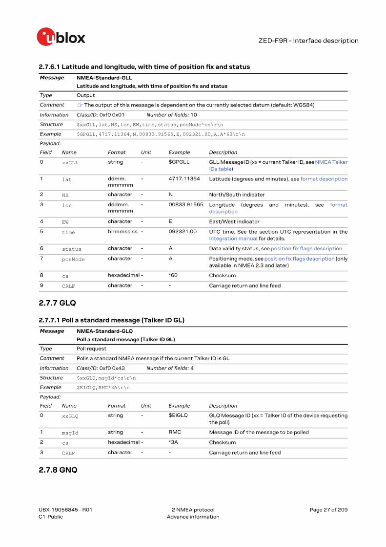
Example $GPGLL,4717.11364,N,00833.91565,E,092321.00,A,A*60\r\n
Payload:
Field Name Format Unit Example Description
0 xxGLL string - $GPGLL GLL Message ID (xx = current Talker ID, see NMEA TalkerIDs table)
1 lat ddmm.mmmmm
- 4717.11364 Latitude (degrees and minutes), see format description
2 NS character - N North/South indicator
3 lon dddmm.mmmmm
- 00833.91565 Longitude (degrees and minutes), see formatdescription
4 EW character - E East/West indicator
5 time hhmmss.ss - 092321.00 UTC time. See the section UTC representation in theIntegration manual for details.
6 status character - A Data validity status, see position fix flags description
7 posMode character - A Positioning mode, see position fix flags description (onlyavailable in NMEA 2.3 and later)
8 cs hexadecimal - *60 Checksum
9 CRLF character - - Carriage return and line feed
2.7.7 GLQ
2.7.7.1 Poll a standard message (Talker ID GL)
Message NMEA-Standard-GLQ
Poll a standard message (Talker ID GL)
Type Poll request
Comment Polls a standard NMEA message if the current Talker ID is GL
Information Class/ID: 0xf0 0x43 Number of fields: 4
Structure $xxGLQ,msgId*cs\r\n
Example $EIGLQ,RMC*3A\r\n
Payload:
Field Name Format Unit Example Description
0 xxGLQ string - $EIGLQ GLQ Message ID (xx = Talker ID of the device requestingthe poll)
1 msgId string - RMC Message ID of the message to be polled
2 cs hexadecimal - *3A Checksum
3 CRLF character - - Carriage return and line feed
2.7.8 GNQ
UBX-19056845 - R01
2 NMEA protocol Page 27 of 209C1-Public Advance information
ZED-F9R - Interface description
2.7.8.1 Poll a standard message (Talker ID GN)
Message NMEA-Standard-GNQ
Poll a standard message (Talker ID GN)
Type Poll request
Comment Polls a standard NMEA message if the current Talker ID is GN
Information Class/ID: 0xf0 0x42 Number of fields: 4
Structure $xxGNQ,msgId*cs\r\n
Example $EIGNQ,RMC*3A\r\n
Payload:
Field Name Format Unit Example Description
0 xxGNQ string - $EIGNQ GNQ Message ID (xx = Talker ID of the device requestingthe poll)
1 msgId string - RMC Message ID of the message to be polled
2 cs hexadecimal - *3A Checksum
3 CRLF character - - Carriage return and line feed
2.7.9 GNS
2.7.9.1 GNSS fix data
Message NMEA-Standard-GNS
GNSS fix data
Type Output
Comment Time and position, together with GNSS fixing-related data (number of satellites in use, and the resultingHDOP, age of differential data if in use, etc.).
☞ The output of this message is dependent on the currently selected datum (default: WGS84)
Information Class/ID: 0xf0 0x0d Number of fields: 16
0 xxGNS string - $GPGNS GNS Message ID (xx = current Talker ID, see NMEATalker IDs table)
1 time hhmmss.ss - 091547.00 UTC time. See the section UTC representation in theIntegration manual for details.
2 lat ddmm.mmmmm
- 5114.50897 Latitude (degrees and minutes), see format description
3 NS character - N North/South indicator
4 lon dddmm.mmmmm
- 00012.28663 Longitude (degrees and minutes), see formatdescription
5 EW character - E East/West indicator
6 posMode character - AAAA Positioning mode, see position fix flags description.First character for GPS, second character for GLONASS,third character for Galileo, fourth character for BeiDou
7 numSV numeric - 10 Number of satellites used (range: 0-99)
8 HDOP numeric - 0.83 Horizontal Dilution of Precision
UBX-19056845 - R01
2 NMEA protocol Page 28 of 209C1-Public Advance information
ZED-F9R - Interface description
9 alt numeric m 111.1 Altitude above mean sea level
10 sep numeric m 45.6 Geoid separation: difference between ellipsoid andmean sea level
11 diffAge numeric s - Age of differential corrections (null when DGPS is notused)
12 diffStation numeric - - ID of station providing differential corrections (null whenDGPS is not used)
13 navStatus character - V Navigational status indicator: V (Equipment is notproviding navigational status information, fixed field,only available in NMEA 4.10 and later)
14 cs hexadecimal - *71 Checksum
15 CRLF character - - Carriage return and line feed
2.7.10 GPQ
2.7.10.1 Poll a standard message (Talker ID GP)
Message NMEA-Standard-GPQ
Poll a standard message (Talker ID GP)
Type Poll request
Comment Polls a standard NMEA message if the current Talker ID is GP
Information Class/ID: 0xf0 0x40 Number of fields: 4
Structure $xxGPQ,msgId*cs\r\n
Example $EIGPQ,RMC*3A\r\n
Payload:
Field Name Format Unit Example Description
0 xxGPQ string - $EIGPQ GPQ Message ID (xx = Talker ID of the device requestingthe poll)
1 msgId string - RMC Message ID of the message to be polled
2 cs hexadecimal - *3A Checksum
3 CRLF character - - Carriage return and line feed
2.7.11 GQQ
2.7.11.1 Poll a standard message (Talker ID GQ)
Message NMEA-Standard-GQQ
Poll a standard message (Talker ID GQ)
Type Poll request
Comment Polls a standard NMEA message if the current Talker ID is GQ
Information Class/ID: 0xf0 0x47 Number of fields: 4
Structure $xxGQQ,msgId*cs\r\n
Example $EIGQQ,RMC*3A\r\n
Payload:
Field Name Format Unit Example Description
0 xxGQQ string - $EIGQQ GQQ Message ID (xx = Talker ID of the device requestingthe poll)
1 msgId string - RMC Message ID of the message to be polled
UBX-19056845 - R01
2 NMEA protocol Page 29 of 209C1-Public Advance information
ZED-F9R - Interface description
2 cs hexadecimal - *3A Checksum
3 CRLF character - - Carriage return and line feed
2.7.12 GRS
2.7.12.1 GNSS range residuals
Message NMEA-Standard-GRS
GNSS range residuals
Type Output
Comment If less than 12 SVs are available, the remaining fields are output empty. If more than 12 SVs are used, only theresiduals of the first 12 SVs are output, in order to remain consistent with the NMEA standard.
In a multi-GNSS system this message will be output multiple times, once for each GNSS.
☞ This message relates to associated GGA and GSA messages.
Information Class/ID: 0xf0 0x06 Number of fields: 19
0 xxGRS string - $GPGRS GRS Message ID (xx = current Talker ID, see NMEATalker IDs table)
1 time hhmmss.ss - 082632.00 UTC time of associated position fix. See the section UTCrepresentation in the Integration manual for details.
2 mode digit - 1 Computation method used:
• 1 = Residuals were recomputed after the GGAposition was computed (fixed)
Start of repeated group (12 times)
3 + n residual numeric m 0.54 Range residuals for SVs used in navigation. The SV ordermatches the order from the GSA sentence
End of repeated group (12 times)
15 systemId hexadecimal - 1 NMEA-defined GNSS system ID, see Signal Identifierstable (only available in NMEA 4.10 and later)
16 signalId hexadecimal - - NMEA-defined GNSS signal ID, see Signal Identifierstable (only available in NMEA 4.10 and later)
17 cs hexadecimal - *70 Checksum
18 CRLF character - - Carriage return and line feed
2.7.13 GSA
2.7.13.1 GNSS DOP and active satellites
Message NMEA-Standard-GSA
GNSS DOP and active satellites
Type Output
Comment The GNSS receiver operating mode, satellites used for navigation, and DOP values.
• If less than 12 SVs are used for navigation, the remaining fields are left empty. If more than 12 SVs areused for navigation, only the IDs of the first 12 are output.
• The SV numbers (fields 'svid') are in the range of 1 to 32 for GPS satellites, and 33 to 64 for SBASsatellites (33 = SBAS PRN 120, 34 = SBAS PRN 121, and so on)
In a multi-GNSS system this message will be output multiple times, once for each GNSS.
UBX-19056845 - R01
2 NMEA protocol Page 30 of 209C1-Public Advance information
ZED-F9R - Interface description
Information Class/ID: 0xf0 0x02 Number of fields: 21
Example $GPGST,082356.00,1.8,,,,1.7,1.3,2.2*7E\r\n
Payload:
Field Name Format Unit Example Description
0 xxGST string - $GPGST GST Message ID (xx = current Talker ID, see NMEATalker IDs table)
1 time hhmmss.ss - 082356.00 UTC time of associated position fix. See the section UTCrepresentation in the Integration manual for details.
2 rangeRms numeric m 1.8 RMS value of the standard deviation of the ranges
3 stdMajor numeric m - Standard deviation of semi-major axis
4 stdMinor numeric m - Standard deviation of semi-minor axis
5 orient numeric deg - Orientation of semi-major axis
6 stdLat numeric m 1.7 Standard deviation of latitude error
7 stdLong numeric m 1.3 Standard deviation of longitude error
8 stdAlt numeric m 2.2 Standard deviation of altitude error
UBX-19056845 - R01
2 NMEA protocol Page 31 of 209C1-Public Advance information
ZED-F9R - Interface description
9 cs hexadecimal - *7E Checksum
10 CRLF character - - Carriage return and line feed
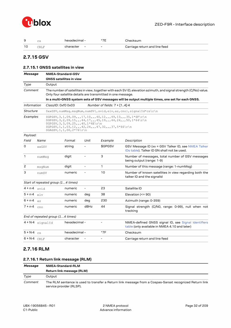
2.7.15 GSV
2.7.15.1 GNSS satellites in view
Message NMEA-Standard-GSV
GNSS satellites in view
Type Output
Comment The number of satellites in view, together with each SV ID, elevation azimuth, and signal strength (C/No) value.Only four satellite details are transmitted in one message.
In a multi-GNSS system sets of GSV messages will be output multiple times, one set for each GNSS.
Information Class/ID: 0xf0 0x03 Number of fields: 7 + [1..4]·4
0 xxGSV string - $GPGSV GSV Message ID (xx = GSV Talker ID, see NMEA TalkerIDs table). Talker ID GN shall not be used.
1 numMsg digit - 3 Number of messages, total number of GSV messagesbeing output (range: 1-9)
2 msgNum digit - 1 Number of this message (range: 1-numMsg)
3 numSV numeric - 10 Number of known satellites in view regarding both thetalker ID and the signalId
Start of repeated group (1…4 times)
4 + n·4 svid numeric - 23 Satellite ID
5 + n·4 elv numeric deg 38 Elevation (<= 90)
6 + n·4 az numeric deg 230 Azimuth (range: 0-359)
7 + n·4 cno numeric dBHz 44 Signal strength (C/N0, range: 0-99), null when nottracking
End of repeated group (1…4 times)
4 + N·4 signalId hexadecimal - - NMEA-defined GNSS signal ID, see Signal Identifierstable (only available in NMEA 4.10 and later)
5 + N·4 cs hexadecimal - *7F Checksum
6 + N·4 CRLF character - - Carriage return and line feed
2.7.16 RLM
2.7.16.1 Return link message (RLM)
Message NMEA-Standard-RLM
Return link message (RLM)
Type Output
Comment The RLM sentence is used to transfer a Return link message from a Cospas-Sarsat recognized Return linkservice provider (RLSP).
UBX-19056845 - R01
2 NMEA protocol Page 32 of 209C1-Public Advance information
ZED-F9R - Interface description
The RLM sentence supports communications to an emitting beacon once a distress alert has been detected,located and confirmed. The communications may include acknowledgement of the alert to the emittingbeacon as well as optional text messages, and may also include remote beacon configuration and testing.
Information Class/ID: 0xf0 0x0b Number of fields: 7
0 xxRLM string - $GARLM RLM message ID (xx = current Talker ID, see NMEATalker IDs table)
1 beacon hexadecimal - 00000078A9FBAD5
Beacon ID, identifies beacon intended to receive thismessage (fixed length 15 hexadecimal character field)
2 time hhmmss.ss - 083559.00 Time of reception field to indicate RLM timestampin UTC. See the section UTC representation in theIntegration manual for details.
3 code character - 3 Message code field to identify type of RLM MessageService:
• 0 = Reserved for future RLM services• 1 = Acknowledgement service RLM• 2 = Command service RLM• 3 = Message service RLM• 4-E = Reserved for future RLM services• F = Test service RLM (currently used only by the
Galileo program)
4 body hexadecimal - C45B Message body encapsulates the data parametersprovided by the RLSP into hexadecimal format.
5 cs hexadecimal - *57 Checksum
6 CRLF character - - Carriage return and line feed
2.7.17 RMC
2.7.17.1 Recommended minimum data
Message NMEA-Standard-RMC
Recommended minimum data
Type Output
Comment The recommended minimum sentence defined by NMEA for GNSS system data.
☞ The output of this message is dependent on the currently selected datum (default: WGS84)
Information Class/ID: 0xf0 0x04 Number of fields: 16
Example $GPRMC,083559.00,A,4717.11437,N,00833.91522,E,0.004,77.52,091202,,,A,V*57\r\n
Payload:
Field Name Format Unit Example Description
0 xxRMC string - $GPRMC RMC Message ID (xx = current Talker ID, see NMEATalker IDs table)
1 time hhmmss.ss - 083559.00 UTC time. See the section UTC representation in theIntegration manual for details.
2 status character - A Data validity status, see position fix flags description
3 lat ddmm.mmmmm
- 4717.11437 Latitude (degrees and minutes), see format description
UBX-19056845 - R01
2 NMEA protocol Page 33 of 209C1-Public Advance information
ZED-F9R - Interface description
4 NS character - N North/South indicator
5 lon dddmm.mmmmm
- 00833.91522 Longitude (degrees and minutes), see formatdescription
6 EW character - E East/West indicator
7 spd numeric knots 0.004 Speed over ground
8 cog numeric deg 77.52 Course over ground
9 date ddmmyy - 091202 Date in day, month, year format. See the section UTCrepresentation in the Integration manual for details.
10 mv numeric deg - Magnetic variation value
11 mvEW character - - Magnetic variation E/W indicator
12 posMode character - A Mode Indicator, see position fix flags description (onlyavailable in NMEA 2.3 and later)
13 navStatus character - V Navigational status indicator: V (Equipment is notproviding navigational status information, fixed field,only available in NMEA 4.10 and later)
14 cs hexadecimal - *57 Checksum
15 CRLF character - - Carriage return and line feed
2.7.18 THS
2.7.18.1 True heading and status
Message NMEA-Standard-THS
True heading and status
Type Output
Comment Actual vehicle heading in degrees produced by any device or system producing true heading. This sentenceincludes a Mode indicator field providing critical safety-related information about the heading data, andreplaces the HDT sentence.
Information Class/ID: 0xf0 0x0e Number of fields: 5
Structure $xxTHS,headt,mi*cs\r\n
Example $GPTHS,77.52,E*32\r\n
Payload:
Field Name Format Unit Example Description
0 xxTHS string - $GPTHS THS Message ID (xx = current Talker ID, see NMEATalker IDs table)
1 headt numeric degrees 77.52 Heading of vehicle (true)
2 mi character - E Mode indicator:
• A = Autonomous• E = Estimated (dead reckoning)• M = Manual input• S = Simulator• V = Data not valid
3 cs hexadecimal - *32 Checksum
4 CRLF character - - Carriage return and line feed
2.7.19 TXT
UBX-19056845 - R01
2 NMEA protocol Page 34 of 209C1-Public Advance information
ZED-F9R - Interface description
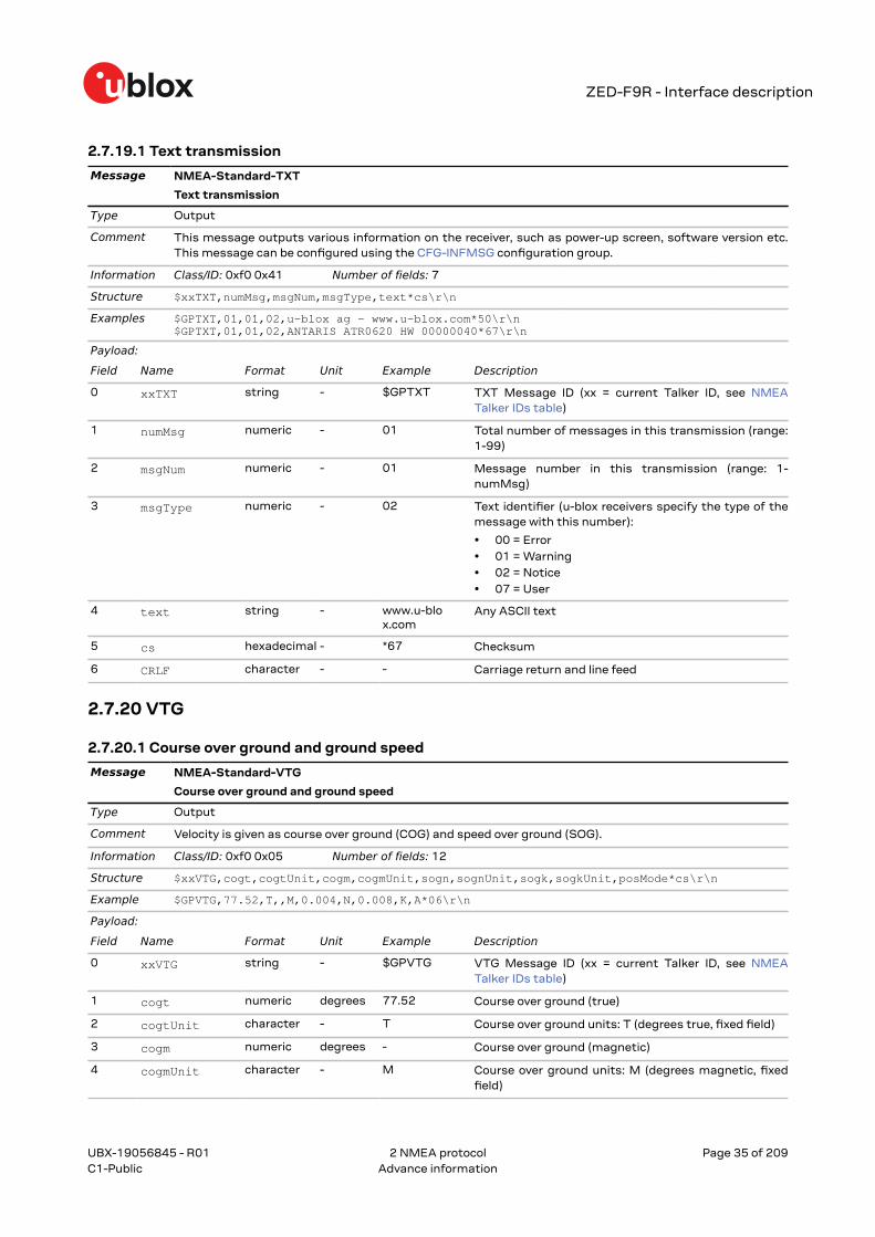
2.7.19.1 Text transmission
Message NMEA-Standard-TXT
Text transmission
Type Output
Comment This message outputs various information on the receiver, such as power-up screen, software version etc.This message can be configured using the CFG-INFMSG configuration group.
Information Class/ID: 0xf0 0x41 Number of fields: 7
2 portId numeric - 1 ID of communication port. See the sectionCommunication ports in the Integration manual fordetails.
3 inProto hexadecimal - 0007 Input protocol mask. Bitmask, specifying whichprotocols(s) are allowed for input. See the sectionCommunication ports in the Integration manual fordetails.
4 outProto hexadecimal - 0003 Output protocol mask. Bitmask, specifying whichprotocols(s) are allowed for input. See the sectionCommunication ports in the Integration manual fordetails.
5 baudrate numeric bits/s 19200 Baud rate
6 autobauding numeric - - Autobauding: 1=enable, 0=disable (not supported on u-blox 5, set to 0)
7 cs hexadecimal - *25 Checksum
8 CRLF character - - Carriage return and line feed
2.8.2 POSITION (PUBX,00)
2.8.2.1 Poll a PUBX,00 message
Message NMEA-PUBX-POSITION
Poll a PUBX,00 message
Type Poll request
Comment A PUBX,00 message is polled by sending the PUBX,00 message without any data fields.
Information Class/ID: 0xf1 0x00 Number of fields: 4
1 msgId numeric - 00 Set to 00 to poll a PUBX,00 message
2 cs hexadecimal - *33 Checksum
3 CRLF character - - Carriage return and line feed
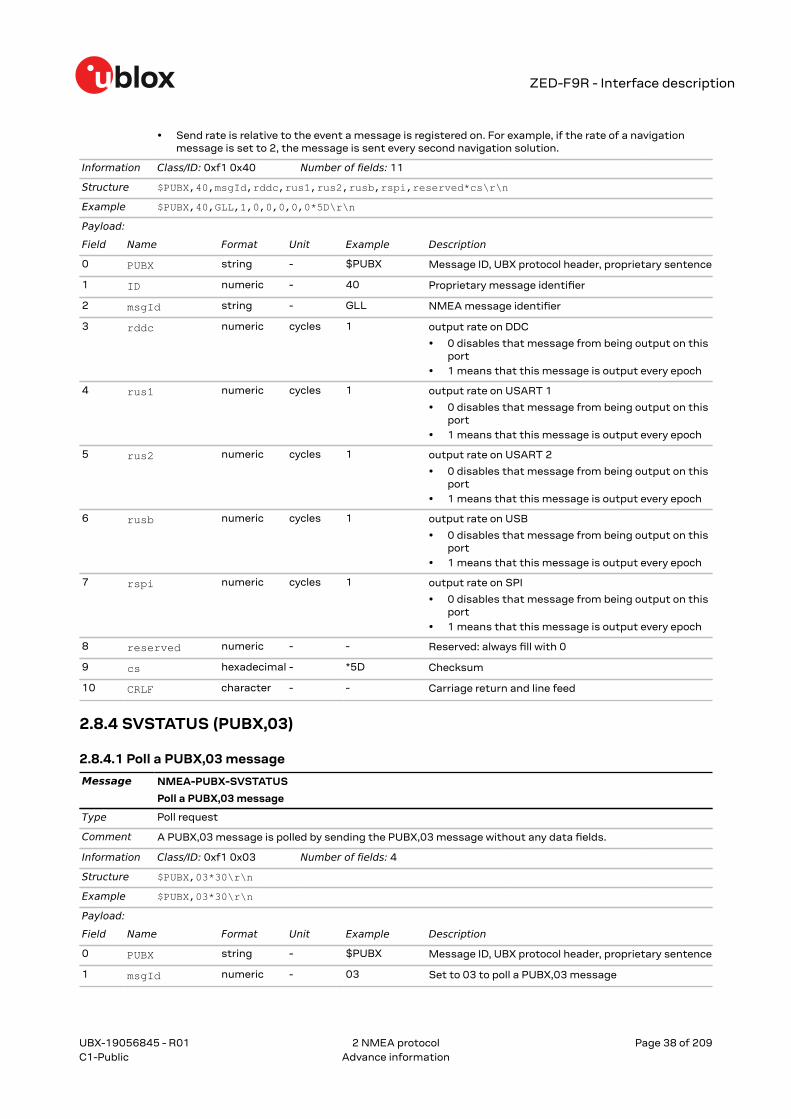
2.8.3 RATE (PUBX,40)
2.8.3.1 Set NMEA message output rate
Message NMEA-PUBX-RATE
Set NMEA message output rate
Type Set
Comment Set/Get message rate configuration (s) to/from the receiver.
UBX-19056845 - R01
2 NMEA protocol Page 37 of 209C1-Public Advance information
ZED-F9R - Interface description
• Send rate is relative to the event a message is registered on. For example, if the rate of a navigationmessage is set to 2, the message is sent every second navigation solution.
Information Class/ID: 0xf1 0x40 Number of fields: 11
1 msgId numeric - 04 Set to 04 to poll a PUBX,04 message
2 cs hexadecimal - *37 Checksum
3 CRLF character - - Carriage return and line feed
UBX-19056845 - R01
2 NMEA protocol Page 39 of 209C1-Public Advance information
ZED-F9R - Interface description
3 UBX protocol
3.1 UBX protocol key featuresu-blox receivers support a u-blox-proprietary protocol to communicate with a host computer. Thisprotocol has the following key features:
• Compact – uses 8-bit binary data.• Checksum protected – uses a low-overhead checksum algorithm• Modular – uses a two-stage message identifier (Class and Message ID)
3.2 UBX frame structureThe structure of a basic UBX frame is shown in the following diagram.
• Every frame starts with a 2-byte preamble consisting of two synchronization characters: 0xb5and 0x62.
• A 1-byte message class field follows. A class is a group of messages that are related to eachother.
• A 1-byte message ID field defines the message that is to follow.• A 2-byte length field follows. The length is defined as being that of the payload only. It does not
include the preamble, message class, message ID, length, or UBX checksum fields. The numberformat of the length field is an unsigned little-endian 16-bit integer (a "U2" in UBX data types).
• The payload field contains a variable number (= length) of bytes.• The two 1-byte CK_A and CK_B fields hold a 16-bit checksum whose calculation is defined in
UBX checksum section. This concludes the frame.
UBX-19056845 - R01
3 UBX protocol Page 40 of 209C1-Public Advance information
ZED-F9R - Interface description
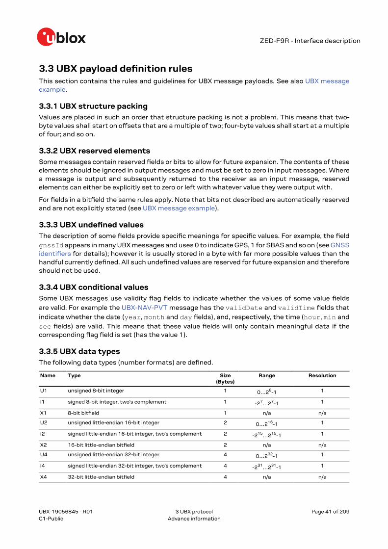
3.3 UBX payload definition rulesThis section contains the rules and guidelines for UBX message payloads. See also UBX messageexample.
3.3.1 UBX structure packingValues are placed in such an order that structure packing is not a problem. This means that two-byte values shall start on offsets that are a multiple of two; four-byte values shall start at a multipleof four; and so on.
3.3.2 UBX reserved elementsSome messages contain reserved fields or bits to allow for future expansion. The contents of theseelements should be ignored in output messages and must be set to zero in input messages. Wherea message is output and subsequently returned to the receiver as an input message, reservedelements can either be explicitly set to zero or left with whatever value they were output with.
For fields in a bitfield the same rules apply. Note that bits not described are automatically reservedand are not explicitly stated (see UBX message example).
3.3.3 UBX undefined valuesThe description of some fields provide specific meanings for specific values. For example, the field
gnssId appears in many UBX messages and uses 0 to indicate GPS, 1 for SBAS and so on (see GNSSidentifiers for details); however it is usually stored in a byte with far more possible values than thehandful currently defined. All such undefined values are reserved for future expansion and thereforeshould not be used.
3.3.4 UBX conditional valuesSome UBX messages use validity flag fields to indicate whether the values of some value fields
are valid. For example the UBX-NAV-PVT message has the validDate and validTime fields that
indicate whether the date (year, month and day fields), and, respectively, the time (hour, min and
sec fields) are valid. This means that these value fields will only contain meaningful data if thecorresponding flag field is set (has the value 1).
3.3.5 UBX data typesThe following data types (number formats) are defined.
Name Type Size(Bytes)
Range Resolution
U1 unsigned 8-bit integer 1 0…28-1 1
I1 signed 8-bit integer, two's complement 1 -27…27-1 1
X1 8-bit bitfield 1 n/a n/a
U2 unsigned little-endian 16-bit integer 2 0…216-1 1
I2 signed little-endian 16-bit integer, two's complement 2 -215…215-1 1
U:n unsigned bitfield value of n bits width var. variable variable
I:n signed (two's complement) bitfield value of n bits width var. variable variable
S:n signed bitfield value of n bits width, in sign (mostsignificant bit) and magnitude (remaining bits) notation
var. variable variable
3.3.6 UBX fields scale and unitFields in UBX messages can have a unit defined. Whenever possible, SI units and symbols are used(e.g. "m" for meters, "s" for seconds). For civil (UTC) time representation units of years (y), months(month), days (d), hours (h), minutes (min) and seconds (s) are used.
Fields in UBX messages can have a scale factor defined. Unity (factor 1) is assumed if no scale isspecified. For integer type fields this is often combined with a unit. When a scale is combined witha unit, the scale represents the smallest storage unit. For example, if meters (m) are expressed(stored) in centimeters the scale would be 0.01 (or 1e-2). This is equivalent of specifying a unit ofcentimeters (cm) and no scale.
3.3.7 UBX repeated fieldsThere are two types of repetitions in UBX messages. The first type specifies that a single field isrepeated a constant number of times. This repetition is defined in the type of the field. For example,
the UBX message example can specify a field data of type U1[5]. In this case the data field shouldbe interpreted as an array of five U1 values.
The second type of repetition in messages is referred to as repeated groups, which groups one ormore fields into a block of payload data. There are several types of repetition:
• The number of repetitions of variable-by-field group is indicated by another, earlier field in thesame message. The number of repetitions can be zero or more, depending on the value of thereferenced field.
• A constant group has a constant number of repetitions.• An optional group is repeated zero or one times, depending on the available payload data. That
is, the fields are present in the message only if the payload of the message is large enough tocover the whole group of fields.
• The number of repetitions of a variable-by-size group is given by the available payload size. Thegroup will repeat until there is not enough payload data left to cover the whole group of fieldsanother time.
Note that only some combinations of repeated groups of fields are possible in a single message. Seealso UBX payload decoding.
3.3.8 UBX payload decodingUBX message payloads are designed so that the data (fields) can be extracted by a single passthrough the payload from start to end. Fixed-size messages are the trivial case where the offset ofall fields is unambiguously defined. Variable-size messages have variable number of repetitions ofone or multiple groups of fields. For groups where the number of repetitions is given by the valueof another field, that field can always be found at a fixed offset in the message payload before therespective group of fields. Groups whose number of repetitions depend on the payload size can only
UBX-19056845 - R01
3 UBX protocol Page 42 of 209C1-Public Advance information
ZED-F9R - Interface description
be the last group of fields in a message and only one such group may exist in a message. See alsoUBX repeated fields.
3.4 UBX checksumThe checksum is calculated over the message, starting and including the class field up until, butexcluding, the checksum fields (see the figure UBX frame structure).
The checksum algorithm used is the 8-bit Fletcher algorithm, which is used in the TCP standardRFC 1145). This algorithm works as follows:
• Buffer[N] is an array of bytes that contains the data over which the checksum is to becalculated.
• The two CK_A and CK_A values are 8-bit unsigned integers, only! If implementing with larger-sized integer values, make sure to mask both CK_A and CK_B with the value 0xff after bothoperations in the loop.
• After the loop, the two U1 values contain the checksum, transmitted after the messagepayload, which concludes the frame.
1 CK_A = 0, CK_B = 02 For (I = 0; I < N; I++)3 {4 CK_A = CK_A + Buffer[I]5 CK_B = CK_B + CK_A6 }
3.5 UBX message flowThere are certain features associated with the messages being sent back and forth:
3.5.1 UBX acknowledgementWhen messages from the class CFG are sent to the receiver, the receiver will send an"acknowledge" (UBX-ACK-ACK) or a "not acknowledge" (UBX-ACK-NAK) message back to thesender, depending on whether or not the message was processed correctly.
Some messages from other classes also use the same acknowledgement mechanism.
3.5.2 UBX polling mechanismAll messages that are output by the receiver in a periodic manner (i.e. messages in classes UBX-MON, UBX-NAV and UBX-RXM) and Get/Set type messages, such as the configuration messages inthe UBX-CFG class, can also be polled.
The UBX protocol is designed so that messages can be polled by sending the message required tothe receiver but without a payload (or with just a single parameter that identifies the poll request).The receiver then responds with the same message with the payload populated.
3.6 GNSS, satellite and signal numberingSee GNSS, satellite and signal identifiers for details on how GNSS, satellites and signals arenumbered in the UBX protocol.
3.7 UBX message exampleThis is an example of the definition of UBX messages as shown in the following sections.
UBX-19056845 - R01
3 UBX protocol Page 43 of 209C1-Public Advance information
This is a comment that describes the use of the demo example message.
There can be references to other sections in the documentation (such as: UBX protocol).
☞ Note that there can be important remarks here.
Header Class ID Length (bytes) Payload ChecksumMessage❹Structure 0xb5 0x62 0x01 0x07 16 + numRepeat*4 see below CK_A CK_B
Payload description: ❺
Byte offset Type Name Scale Unit Description
0 U4 aField - - a field that contains an unsigned integer withno particular scale or unit
4 I4 anotherField 1e-2 m a field that contains a length in meters (m)with a scale of 1e-2 (= 0.01), i.e. a length incentimeters
8 X2 bitfield ❻ - - this field contains flags or values smaller thanone byte, whose definition follows below (bitsnot described are reserved)
bit 0 U:1 aFieldValid - - the first bit in bitfield indicates whether theaField is valid or not (see UBX conditionalvalues)
bit 1 U:1 someFlag - - the second bit is a flag (1 = true, 0 = false)
bits 5…2 U:4 aBitFieldValue - - a 4-bits value (range: 0…15)
10 U1[5] ❼ reserved0 - - a reserved field, whose value shall be ignored(in output messages) or set to 0 (in inputmessages)
15 U1 numRepeat - - number of repetitions in the group of fieldsbelow
Start of repeated group (numRepeat times) ❽
16 + n*4 I2 someValue - - a signed value in a repeated group of fields
18 + n*4 U2 anotherValue - - another value in a repeated group of fields
End of repeated group (numRepeat times)
❶ The first line shows the message name (see Naming). The second line shows a short descriptionof the message.
❷ The message type (see Message types).
❸ This section contains comments that describe the message. Often links to other related sectionsin the documentation or other related messages are found here.
❹ The message structure gives the parameters for the UBX frame structure, notably the messageclass and message ID values and the payload length. For many messages the payload length isa fixed number (of bytes). Messages that contain repeated blocks of information (fields) have avariable payload (see UBX repeated fields).
❺ The message payload definition is given as a list of fields and their parameters. Each field startsat a specified offset (in bytes) in the payload (see also UBX structure packing), is of a specific type
UBX-19056845 - R01
3 UBX protocol Page 44 of 209C1-Public Advance information
ZED-F9R - Interface description
(see UBX data types), has a unique name (within the message), and a description. Optionally, fieldscan have a scale and/or a unit (see UBX fields scale and unit).
❻ Bitfields ("X" types) are broken down into smaller parts. Each part can be one or more bits wide.Values that are two or more bits wide can be unsigned or one of two signed value representation(see UBX data types). Note that the ten unused bits 15…6 are not explicitly stated as UBX reservedelements.
❼ Fields can be arrays of values of the same type (see UBX repeated fields).
❽ Groups of fields can be repeated in the payload. The number of repetitions can be given by anotherfield in the message (this example), a constant number, zero or one times (known as "optionalgroup"), or derived from the remaining payload size (labeled as "repeated N times"). See also UBXrepeated fields and UBX payload decoding.
UBX-NAV-DOP 0x01 0x04 • Dilution of precision (Periodic/polled)
UBX-NAV-EELL 0x01 0x3d • Position error ellipse parameters (Periodic/polled)
UBX-NAV-EOE 0x01 0x61 • End of epoch (Periodic)
UBX-NAV-GEOFENCE 0x01 0x39 • Geofencing status (Periodic/polled)
UBX-NAV-HPPOSECEF 0x01 0x13 • High precision position solution in ECEF (Periodic/polled)
UBX-NAV-HPPOSLLH 0x01 0x14 • High precision geodetic position solution (Periodic/polled)
UBX-NAV-ORB 0x01 0x34 • GNSS orbit database info (Periodic/polled)
UBX-19056845 - R01
3 UBX protocol Page 46 of 209C1-Public Advance information
ZED-F9R - Interface description
Message Class/ID Description (Type)UBX-NAV-POSECEF 0x01 0x01 • Position solution in ECEF (Periodic/polled)
UBX-NAV-POSLLH 0x01 0x02 • Geodetic position solution (Periodic/polled)
UBX-NAV-PVT 0x01 0x07 • Navigation position velocity time solution (Periodic/polled)
UBX-NAV-RELPOSNED 0x01 0x3c • Relative positioning information in NED frame (Periodic/polled)
UBX-NAV-SAT 0x01 0x35 • Satellite information (Periodic/polled)
UBX-NAV-SBAS 0x01 0x32 • SBAS status data (Periodic/polled)
UBX-NAV-SIG 0x01 0x43 • Signal information (Periodic/polled)
UBX-NAV-SLAS 0x01 0x42 • QZSS L1S SLAS status data (Periodic/polled)
UBX-NAV-STATUS 0x01 0x03 • Receiver navigation status (Periodic/polled)
UBX-NAV-TIMEBDS 0x01 0x24 • BeiDou time solution (Periodic/polled)
UBX-NAV-TIMEGAL 0x01 0x25 • Galileo time solution (Periodic/polled)
UBX-NAV-TIMEGLO 0x01 0x23 • GLONASS time solution (Periodic/polled)
UBX-NAV-TIMEGPS 0x01 0x20 • GPS time solution (Periodic/polled)
UBX-NAV-TIMELS 0x01 0x26 • Leap second event information (Periodic/polled)
UBX-NAV-TIMEQZSS 0x01 0x27 • QZSS time solution (Periodic/polled)
UBX-NAV-TIMEUTC 0x01 0x21 • UTC time solution (Periodic/polled)
UBX-NAV-VELECEF 0x01 0x11 • Velocity solution in ECEF (Periodic/polled)
UBX-NAV-VELNED 0x01 0x12 • Velocity solution in NED frame (Periodic/polled)
UBX-RXM – Receiver manager messages
UBX-RXM-MEASX 0x02 0x14 • Satellite measurements for RRLP (Periodic/polled)
UBX-RXM-PMREQ 0x02 0x41 • Power management request (Command)
UBX-RXM-RAWX 0x02 0x15 • Multi-GNSS raw measurements (Periodic/polled)
UBX-RXM-RLM 0x02 0x59 • Galileo SAR short-RLM report (Output)• Galileo SAR long-RLM report (Output)
UBX-RXM-RTCM 0x02 0x32 • RTCM input status (Output)
UBX-SEC – Security messages
UBX-SEC-UNIQID 0x27 0x03 • Unique chip ID (Output)
UBX-TIM – Timing messages
UBX-TIM-TM2 0x0d 0x03 • Time mark data (Periodic/polled)
UBX-TIM-TP 0x0d 0x01 • Time pulse time data (Periodic/polled)
UBX-TIM-VRFY 0x0d 0x06 • Sourced time verification (Periodic/polled)
UBX-UPD – Firmware update messages
UBX-UPD-SOS 0x09 0x14 • Poll backup restore status (Poll request)• Create backup in flash (Command)• Clear backup in flash (Command)• Backup creation acknowledge (Output)• System restored from backup (Output)
3.9 UBX-ACK (0x05)The messages in the UBX-ACK class are used to indicate acknowledgement or rejection (i.e. negativeacknowledgement) of input messages, such as UBX-CFG messages.
3.9.1 UBX-ACK-ACK (0x05 0x01)
UBX-19056845 - R01
3 UBX protocol Page 47 of 209C1-Public Advance information
ZED-F9R - Interface description
3.9.1.1 Message acknowledged
Message UBX-ACK-ACK
Message acknowledged
Type Output
Comment Output upon processing of an input message. A UBX-ACK-ACK is sent as soon as possible but at least withinone second.
Header Class ID Length (Bytes) Payload ChecksumMessagestructure 0xb5 0x62 0x05 0x01 2 see below CK_A CK_B
Payload description:
Byte offset Type Name Scale Unit Description
0 U1 clsID - - Class ID of the Acknowledged Message
1 U1 msgID - - Message ID of the Acknowledged Message
3.9.2 UBX-ACK-NAK (0x05 0x00)
3.9.2.1 Message not acknowledged
Message UBX-ACK-NAK
Message not acknowledged
Type Output
Comment Output upon processing of an input message. A UBX-ACK-NAK is sent as soon as possible but at least withinone second.
Header Class ID Length (Bytes) Payload ChecksumMessagestructure 0xb5 0x62 0x05 0x00 2 see below CK_A CK_B
Payload description:
Byte offset Type Name Scale Unit Description
0 U1 clsID - - Class ID of the Not-Acknowledged Message
1 U1 msgID - - Message ID of the Not-Acknowledged Message
3.10 UBX-CFG (0x06)The messages in the UBX-CFG class are used to configure the receiver and poll current configurationvalues as well as for sending commands to the receiver. Unless stated otherwise, any message inthis class sent to the receiver is either acknowledged (by a UBX-ACK-ACK message) if processedsuccessfully or rejected (with a UBX-ACK-NAK message) if processed unsuccessfully.
3.10.1 UBX-CFG-RST (0x06 0x04)
3.10.1.1 Reset receiver / Clear backup data structures
Message UBX-CFG-RST
Reset receiver / Clear backup data structures
Type Command
Comment Do not expect this message to be acknowledged by the receiver.
• Newer FW version will not acknowledge this message at all.• Older FW version will acknowledge this message but the acknowledge may not be sent completely
before the receiver is reset.
Header Class ID Length (Bytes) Payload ChecksumMessagestructure 0xb5 0x62 0x06 0x04 4 see below CK_A CK_B
Payload description:
UBX-19056845 - R01
3 UBX protocol Page 48 of 209C1-Public Advance information
ZED-F9R - Interface description
Byte offset Type Name Scale Unit Description
0 X2 navBbrMask - - BBR sections to clear. The following special sets apply:
• 0x0000 Hot start• 0x0001 Warm start• 0xFFFF Cold start
bit 0 U:1 eph - - Ephemeris
bit 1 U:1 alm - - Almanac
bit 2 U:1 health - - Health
bit 3 U:1 klob - - Klobuchar parameters
bit 4 U:1 pos - - Position
bit 5 U:1 clkd - - Clock drift
bit 6 U:1 osc - - Oscillator parameter
bit 7 U:1 utc - - UTC correction + GPS leap seconds parameters
3.10.2.1 Configure and start a sensor production test
Message UBX-CFG-SPT
Configure and start a sensor production test
Type Get/set
Comment The production test uses the built-in self-test capabilities of an attached sensor.
This message is only supported if a sensor is directly connected to the u-blox receiver.
Header Class ID Length (Bytes) Payload ChecksumMessagestructure 0xb5 0x62 0x06 0x64 12 see below CK_A CK_B
Payload description:
Byte offset Type Name Scale Unit Description
0 U1 version - - Message version (0x00 for this version)
1 U1 reserved0 - - Reserved
2 U2 sensorId - - ID of the sensor to be tested; see UBX-MON-SPT fordefined IDs
4 U1[8] reserved1 - - Reserved
3.10.3 UBX-CFG-VALDEL (0x06 0x8c)
UBX-19056845 - R01
3 UBX protocol Page 49 of 209C1-Public Advance information
ZED-F9R - Interface description
3.10.3.1 Delete configuration item values
Message UBX-CFG-VALDEL
Delete configuration item values
Type Set
Comment Overview:
• This message can be used to delete saved configuration to effectively revert the item values to defaults.• This message can delete saved configuration from the flash configuration layer and the BBR
configuration layer. The changes will not be effective until these layers are loaded into the RAM layer.• This message is limited to containing a maximum of 64 keys up for deletion; i.e. N is a maximum of 64.• This message can be used multiple times and every time the result will be applied immediately. To send
this message multiple times with the result being applied at the end, see version 1 of UBX-CFG-VALDELthat supports transactions.
• This message does not check if the resulting configuration is valid.• See Receiver configuration for details.
This message returns a UBX-ACK-NAK and no configuration is applied:
• if any key is unknown to the receiver FW• if the layer's bitfield does not specify a layer to delete a value from.
Notes:
• If a key is sent multiple times within the same message, then the value is effectively deleted only once.• Attempting to delete items that have not been set before, or that have already been deleted, is
considered a valid request.
Header Class ID Length (Bytes) Payload ChecksumMessagestructure 0xb5 0x62 0x06 0x8c 4 + [0..n]·4 see below CK_A CK_B
Payload description:
Byte offset Type Name Scale Unit Description
0 U1 version - - Message version (0x00 for this version)
1 X1 layers - - The layers where the configuration should be deletedfrom
bit 1 U:1 bbr - - Delete configuration from the BBR layer
bit 2 U:1 flash - - Delete configuration from the Flash layer
2 U1[2] reserved0 - - Reserved
Start of repeated group (N times)
4 + n·4 U4 keys - - Configuration key IDs of the configuration items to bedeleted
• This message can be used to delete saved configuration to effectively revert them to defaults.• This message can delete saved configuration from the flash configuration layer and the BBR
configuration layer. The changes will not be effective until these layers are loaded into the RAM layer.• This message is limited to containing a maximum of 64 keys up for deletion; i.e. N is a maximum of 64.• This message can be used multiple times with the result being managed within a transaction.• This message does not check if the resulting configuration is valid.• See Receiver configuration for details.• See version 0 of UBX-CFG-VALDEL for simplified version of this message.
This message returns a UBX-ACK-NAK, cancels any started transaction, and no configuration is applied:
• if any key within a transaction is unknown to the receiver FW• if an invalid transaction state transition is requested
UBX-19056845 - R01
3 UBX protocol Page 50 of 209C1-Public Advance information
ZED-F9R - Interface description
• if the layer's bitfield changes within a transaction• if the layer's bitfield does not specify a layer to delete a value from.
Notes:
• Any request for another UBX-CFG- message type (including UBX-CFG-VALSET and UBX-CFG-VALGET)will cancel any started transaction, and no configuration is applied.
• This message can be sent with no keys to delete for the purposes of managing the transaction statetransition.
• If a key is sent multiple times within the same message or within the same transaction, then the value iseffectively deleted only once.
• Attempting to delete items that have not been set before, or that have already been deleted, isconsidered a valid request.
Header Class ID Length (Bytes) Payload ChecksumMessagestructure 0xb5 0x62 0x06 0x8c 4 + [0..n]·4 see below CK_A CK_B
Payload description:
Byte offset Type Name Scale Unit Description
0 U1 version - - Message version (0x01 for this version)
1 X1 layers - - The layers where the configuration should be deletedfrom
bit 1 U:1 bbr - - Delete configuration from the BBR layer
bit 2 U:1 flash - - Delete configuration from the Flash layer
2 X1 transaction - - Transaction action to be applied:
bits 1…0 U:2 action - - Transaction action to be applied:
• 0 = Transactionless UBX-CFG-VALDEL: In thenext UBX-CFG-VALDEL, it can be either 0 or 1.If a transaction has not yet been started, theincoming configuration is applied. If a transactionhas already been started, cancels any startedtransaction and the incoming configuration isapplied.
• 1 = (Re)Start deletion transaction: In the nextUBX-CFG-VALDEL, it can be either 0, 1, 2 or3. If a transaction has not yet been started, atransaction will be started. If a transaction hasalready been started, restarts the transaction,effectively removing all previous non-applied UBX-CFG-VALDEL messages.
• 2 = Deletion transaction ongoing: In the next UBX-CFG-VALDEL, it can be either 0, 1, 2 or 3.
• 3 = Apply and end a deletion transaction: In thenext UBX-CFG-VALDEL, it can be either 0 or 1.
3 U1 reserved0 - - Reserved
Start of repeated group (N times)
4 + n·4 U4 keys - - Configuration key IDs of the configuration items to bedeleted
End of repeated group (N times)
3.10.4 UBX-CFG-VALGET (0x06 0x8b)
3.10.4.1 Get configuration items
Message UBX-CFG-VALGET
Get configuration items
Type Poll request
Comment Overview:
UBX-19056845 - R01
3 UBX protocol Page 51 of 209C1-Public Advance information
ZED-F9R - Interface description
• This message is used to get configuration values by providing a list of configuration key IDs, whichidentify the configuration items to retrieve.
• This message can specify the configuration layer where the values of the specified configuration itemsare retrieved from.
• This message is limited to containing a maximum of 64 key IDs.• See Receiver configuration for details.
This message returns a UBX-ACK-NAK:
• if any key is unknown to the receiver FW• if the layer field specifies an invalid layer to get the value from• if the keys array specifies more than 64 key IDs.
Notes:
• If a value is requested multiple times within the same poll request, then the reply will contain it multipletimes.
• The provided keys can be complete key values (group and item specifiers) or wild-card specifications.A complete key value will constitute a request for one key-value pair. A key value that has a valid groupspecifier and 0xffff in the item part of the key value (bits 0-15) constitutes a request for all items in thespecified group. A key with a value of 0xfff in the group part of the key value (bits 16-27) is a request forall items known to the receiver in all groups.
• The response message is limited to containing a maximum of 64 key-value pairs. If there are wild-cardspecifications then there may be more than 64 possible responses. In order to handle this, the 'position'field can specify that the response message should skip this number of key-value pairs before it startsconstructing the message. This allows a large set of values to be retrieved 64 at a time. If the responsecontains less than 64 key-value pairs then all values have been reported, otherwise there may be more toread.
• It is not possible to retrieve configuration values for the same configuration item from multipleconfiguration layers. Separate poll requests must be made for each desired layer.
Header Class ID Length (Bytes) Payload ChecksumMessagestructure 0xb5 0x62 0x06 0x8b 4 + [0..n]·4 see below CK_A CK_B
Payload description:
Byte offset Type Name Scale Unit Description
0 U1 version - - Message version (0x00 for this version)
1 U1 layer - - The layer from which the configuration items shouldbe retrieved:
2 U2 position - - Skip this many key values before constructing outputmessage
Start of repeated group (N times)
4 + n·4 U4 keys - - Configuration key IDs of the configuration items to beretrieved
End of repeated group (N times)
3.10.4.2 Configuration items
Message UBX-CFG-VALGET
Configuration items
Type Polled
Comment This message is output by the receiver to return requested configuration data (key and value pairs).
See Receiver configuration for details.
Header Class ID Length (Bytes) Payload ChecksumMessagestructure 0xb5 0x62 0x06 0x8b 4 + [0..n] see below CK_A CK_B
Payload description:
Byte offset Type Name Scale Unit Description
UBX-19056845 - R01
3 UBX protocol Page 52 of 209C1-Public Advance information
ZED-F9R - Interface description
0 U1 version - - Message version (0x01 for this version)
1 U1 layer - - The layer from which the configuration item wasretrieved:
• 0 - RAM layer• 1 - BBR• 2 - Flash• 7 - Default
2 U2 position - - Number of configuration items skipped in the resultset before constructing this message (mirrors theequivalent field in the request message)
Start of repeated group (N times)
4 + n U1 cfgData - - Configuration data (key and value pairs)
End of repeated group (N times)
3.10.5 UBX-CFG-VALSET (0x06 0x8a)
3.10.5.1 Set configuration item values
Message UBX-CFG-VALSET
Set configuration item values
Type Set
Comment Overview:
• This message is used to set a configuration by providing configuration data (a list of key and valuepairs), which identify the configuration items to change, and their new values.
• This message is limited to containing a maximum of 64 key-value pairs.• This message can be used multiple times and every time the result will be applied immediately. To send
this message multiple times with the result being applied at the end, see version 1 of UBX-CFG-VALSETthat supports transactions.
• See Receiver configuration for details.
This message returns a UBX-ACK-NAK and no configuration is applied:
• if any key is unknown to the receiver FW• if the layer's bitfield does not specify a layer to save a value to• if the requested configuration is not valid. The validity of a configuration is checked only if the message
requests to apply the configuration to the RAM configuration layer.
Notes:
• If a key is sent multiple times within the same message, then the value eventually being applied is thelast sent.
Header Class ID Length (Bytes) Payload ChecksumMessagestructure 0xb5 0x62 0x06 0x8a 4 + [0..n] see below CK_A CK_B
Payload description:
Byte offset Type Name Scale Unit Description
0 U1 version - - Message version (0x00 for this version)
1 X1 layers - - The layers where the configuration should be applied
bit 0 U:1 ram - - Update configuration in the RAM layer
bit 1 U:1 bbr - - Update configuration in the BBR layer
bit 2 U:1 flash - - Update configuration in the Flash layer
2 U1[2] reserved0 - - Reserved
Start of repeated group (N times)
4 + n U1 cfgData - - Configuration data (key and value pairs)
End of repeated group (N times)
UBX-19056845 - R01
3 UBX protocol Page 53 of 209C1-Public Advance information
ZED-F9R - Interface description
3.10.5.2 Set configuration item values (with transaction)
Message UBX-CFG-VALSET
Set configuration item values (with transaction)
Type Set
Comment Overview:
• This message is used to set a configuration by providing configuration data (a list of key and valuepairs), which identify the configuration items to change, and their new values.
• This message is limited to containing a maximum of 64 key-value pairs.• This message can be used multiple times with the result being managed within a transaction. Within
a transaction there is no limit on the number key-value pairs; a transaction is effectively limited to thenumber of known keys.
• See Receiver configuration for details.• See version 0 of UBX-CFG-VALSET for simplified version of this message.
This message returns a UBX-ACK-NAK, cancels any started transaction, and no configuration is applied:
• if any key within a transaction is unknown to the receiver FW• if an invalid transaction state transition is requested• if the layer's bitfield changes within a transaction• if the layer's bitfield does not specify a layer to save a value to
This message returns a UBX-ACK-NAK, and no configuration is applied:
• if the requested configuration is not valid. While in a transaction context, only the last message thatrequests to apply the transaction returns a UBX-ACK-NAK. The validity of a configuration is checkedonly if the message requests to apply the configuration to the RAM configuration layer. This also appliesto a transactionless request.
Notes:
• Any request for another UBX-CFG-message type (including UBX-CFG-VALDEL and UBX-CFG-VALGET)will cancel any started transaction, and no configuration is applied.
• This message can be sent with no key/values to set for the purposes of managing the transaction statetransition.
• If a key is sent multiple times within the same message or within the same transaction, then the valueeventually being applied is the last sent.
Header Class ID Length (Bytes) Payload ChecksumMessagestructure 0xb5 0x62 0x06 0x8a 4 + [0..n] see below CK_A CK_B
Payload description:
Byte offset Type Name Scale Unit Description
0 U1 version - - Message version (0x01 for this version)
1 X1 layers - - The layers where the configuration should be applied
bit 0 U:1 ram - - Update configuration in the RAM layer
bit 1 U:1 bbr - - Update configuration in the BBR layer
bit 2 U:1 flash - - Update configuration in the Flash layer
2 U1 transaction - - Transaction action to be applied
bits 1…0 U:2 action - - Transaction action to be applied:
• 0 = Transactionless UBX-CFG-VALSET: In thenext UBX-CFG-VALSET, it can be either 0 or 1.If a transaction has not yet been started, theincoming configuration is applied (if valid). If atransaction has already been started, cancelsany started transaction and the incomingconfiguration is applied (if valid).
• 1 = (Re)Start set transaction: In the nextUBX-CFG-VALSET, it can be either 0, 1, 2 or3. If a transaction has not yet been started, atransaction will be started. If a transaction hasalready been started, restarts the transaction,effectively removing all previous non-applied UBX-CFG-VALSET messages.
UBX-19056845 - R01
3 UBX protocol Page 54 of 209C1-Public Advance information
ZED-F9R - Interface description
• 2 = Set transaction ongoing: In the next UBX-CFG-VALSET, it can be either 0, 1, 2 or 3.
• 3 = Apply and end a set transaction: In the nextUBX-CFG-VALSET, it can be either 0 or 1.
3 U1 reserved0 - - Reserved
Start of repeated group (N times)
4 + n U1 cfgData - - Configuration data (key and value pairs)
End of repeated group (N times)
3.11 UBX-ESF (0x10)The messages in the UBX-ESF class are used to output external sensor fusion information from thereceiver.
3.11.1 UBX-ESF-ALG (0x10 0x14)
3.11.1.1 IMU alignment information
Message UBX-ESF-ALG
IMU alignment information
Type Periodic/polled
Comment This message outputs the IMU alignment angles which define the rotation from the installation-frame to theIMU-frame. In addition, it indicates the automatic IMU-mount alignment status.
Header Class ID Length (Bytes) Payload ChecksumMessagestructure 0xb5 0x62 0x10 0x14 16 see below CK_A CK_B
Payload description:
Byte offset Type Name Scale Unit Description
0 U4 iTOW - ms GPS time of week of the navigation epoch.
See the section iTOW timestamps in Integrationmanual for details.
4 U1 version - - Message version (0x01 for this version)
5 U1 flags - - Flags
bit 0 U:1 autoMntAlgOn - - Automatic IMU-mount alignment on/off bit (0:automatic alignment is not running, 1: automaticalignment is running)
bits 3…1 U:3 status - - Status of the IMU-mount alignment (0: user-defined/fixed angles are used, 1: IMU-mount roll/pitch anglesalignment is ongoing, 2: IMU-mount roll/pitch/yawangles alignment is ongoing, 3: coarse IMU-mountalignment are used, 4: fine IMU-mount alignment areused)
bit 1 U:1 yawAlgError - - IMU-mount yaw alignment error (0: no error, 1: error)
bit 2 U:1 angleError - - IMU-mount misalignment Euler angle singularity error(0: no error, 1: error). If this error bit is set, theIMU-mount roll and IMU-mount yaw angles cannotuniquely be defined due to the singularity issuehappening with installations mounted with a +/- 90degrees misalignment around pitch axis. This is also
UBX-19056845 - R01
3 UBX protocol Page 55 of 209C1-Public Advance information
ZED-F9R - Interface description
known as the 'gimbal-lock' problem affecting rotationsdescribed by Euler angles.
3 UBX protocol Page 56 of 209C1-Public Advance information
ZED-F9R - Interface description
3.11.3.1 External sensor fusion measurements
Message UBX-ESF-MEAS
External sensor fusion measurements
Type Input/output
Comment Contains sensor measurements with timestamp. Optionally, can include timestamp that the message wasreceived at the receiver. Multiple measurements can be included in a single message. (1 measurement persensor type.)
Header Class ID Length (Bytes) Payload ChecksumMessagestructure 0xb5 0x62 0x10 0x02 8 + numMeas·4 + [0,1]·4 see below CK_A CK_B
Payload description:
Byte offset Type Name Scale Unit Description
0 U4 timeTag - - Time tag of measurement generated by externalsensor
4 X2 flags - - Flags. Set all unused bits to zero.
bits 1…0 U:2 timeMarkSent - - Time mark signal was supplied just prior to sendingthis message: 0 = none, 1 = on Ext0, 2 = on Ext1
bit 2 U:1 timeMarkEdge - - Trigger on rising (0) or falling (1) edge of time marksignal
bit 3 U:1 calibTtagValid - - Calibration time tag available. Always set to zero.
bits 15…11 U:5 numMeas - - Number of measurements contained in this message(optional, can be obtained from message size)
6 U2 id - - Identification number of data provider
Start of repeated group (numMeas times)
8 + n·4 X4 data - - data
bits 23…0 U:24 dataField - - Data
bits 29…24 U:6 dataType - - Type of data (0 = no data; 1..63 = data type)
End of repeated group (numMeas times)
Start of optional group
8 +numMeas·4
U4 calibTtag - ms Receiver local time calibrated.
This field must not be supplied when
calibTtagValid is set to 0.
End of optional group
3.11.4 UBX-ESF-RAW (0x10 0x03)
3.11.4.1 Raw sensor measurements
Message UBX-ESF-RAW
Raw sensor measurements
Type Output
Comment The message contains measurements from the active inertial sensors connected to the GNSS receiver
directly via hardware interface. Possible data types for the data field are accelerometer, gyroscope andtemperature readings.
The output rate depends on the output rate of the inertial sensors connected. It includes one sample of everydata type per message.
See the section Raw sensor data output in the Integration manual for details.
Header Class ID Length (Bytes) Payload ChecksumMessagestructure 0xb5 0x62 0x10 0x03 4 + [0..n]·8 see below CK_A CK_B
UBX-19056845 - R01
3 UBX protocol Page 57 of 209C1-Public Advance information
ZED-F9R - Interface description
Payload description:
Byte offset Type Name Scale Unit Description
0 U1[4] reserved0 - - Reserved
Start of repeated group (N times)
4 + n·8 X4 data - - data
Same as in UBX-ESF-MEAS
bits 23…0 U:24 dataField - - data
bits 31…24 U:8 dataType - - type of data (0 = no data; 1..255 = data type)
8 + n·8 U4 sTtag - - sensor time tag
End of repeated group (N times)
3.11.5 UBX-ESF-STATUS (0x10 0x10)
3.11.5.1 External sensor fusion status
Message UBX-ESF-STATUS
External sensor fusion status
Type Periodic/polled
Comment
Header Class ID Length (Bytes) Payload ChecksumMessagestructure 0xb5 0x62 0x10 0x10 16 + numSens·4 see below CK_A CK_B
Payload description:
Byte offset Type Name Scale Unit Description
0 U4 iTOW - ms GPS time of week of the navigation epoch.
See the section iTOW timestamps in Integrationmanual for details.
4 U1 version - - Message version (0x02 for this version)
5 U1[7] reserved0 - - Reserved
12 U1 fusionMode - - Fusion mode:
• 0: Initialization mode: receiver is initializing someunknown values required for doing sensor fusion
• 1: Fusion mode: GNSS and sensor data are usedfor navigation solution computation
• 2: Suspended fusion mode: sensor fusion istemporarily disabled due to e.g. invalid sensordata or detected ferry
• 3: Disabled fusion mode: sensor fusion ispermanently disabled until receiver reset due e.g.to sensor error
See the Fusion filter modes section in Integrationmanual for more details.
13 U1[2] reserved1 - - Reserved
15 U1 numSens - - Number of sensors
Start of repeated group (numSens times)
16 + n·4 X1 sensStatus1 - - Sensor status, part 1
bits 5…0 U:6 type - - Sensor data type. See section Sensor data types in theIntegration manual for details.
bit 6 U:1 used - - If set, sensor data is used for the current sensor fusionsolution.
UBX-19056845 - R01
3 UBX protocol Page 58 of 209C1-Public Advance information
ZED-F9R - Interface description
bit 7 U:1 ready - - If set, sensor is set up (configuration is available ornot required) but not used for computing the currentsensor fusion solution.
17 + n·4 X1 sensStatus2 - - Sensor status, part 2
bits 1…0 U:2 calibStatus - - • 00: Sensor is not calibrated• 01: Sensor is calibrating• 10/11: Sensor is calibrated
Good dead reckoning performance is only possiblewhen all used sensors are calibrated. Depending on thequality of the GNSS signals and the sensor data, thesensors may take a longer time to get calibrated.
bits 3…2 U:2 timeStatus - - • 00: No data• 01: Reception of the first byte used to tag the
measurement• 10: Event input used to tag the measurement• 11: Time tag provided with the data
18 + n·4 U1 freq - Hz Observation frequency
19 + n·4 X1 faults - - Sensor faults
bit 0 U:1 badMeas - - Bad measurements detected
bit 1 U:1 badTTag - - Bad measurement time-tags detected
bit 2 U:1 missingMeas - - Missing or time-misaligned measurements detected
bit 3 U:1 noisyMeas - - High measurement noise-level detected
End of repeated group (numSens times)
3.12 UBX-INF (0x04)Messages in the UBX-INF class are used to output strings from the firmware or application code. Allmessages have an associated type to indicate the nature or priority of the message.
3.12.1 UBX-INF-DEBUG (0x04 0x04)
3.12.1.1 ASCII output with debug contents
Message UBX-INF-DEBUG
ASCII output with debug contents
Type Output
Comment This message has a variable length payload, representing an ASCII string.
Header Class ID Length (Bytes) Payload ChecksumMessagestructure 0xb5 0x62 0x04 0x04 [0..n] see below CK_A CK_B
Payload description:
Byte offset Type Name Scale Unit Description
Start of repeated group (N times)
0 + n CH str - - ASCII Character
End of repeated group (N times)
3.12.2 UBX-INF-ERROR (0x04 0x00)
UBX-19056845 - R01
3 UBX protocol Page 59 of 209C1-Public Advance information
ZED-F9R - Interface description
3.12.2.1 ASCII output with error contents
Message UBX-INF-ERROR
ASCII output with error contents
Type Output
Comment This message has a variable length payload, representing an ASCII string.
Header Class ID Length (Bytes) Payload ChecksumMessagestructure 0xb5 0x62 0x04 0x00 [0..n] see below CK_A CK_B
Payload description:
Byte offset Type Name Scale Unit Description
Start of repeated group (N times)
0 + n CH str - - ASCII Character
End of repeated group (N times)
3.12.3 UBX-INF-NOTICE (0x04 0x02)
3.12.3.1 ASCII output with informational contents
Message UBX-INF-NOTICE
ASCII output with informational contents
Type Output
Comment This message has a variable length payload, representing an ASCII string.
Header Class ID Length (Bytes) Payload ChecksumMessagestructure 0xb5 0x62 0x04 0x02 [0..n] see below CK_A CK_B
Payload description:
Byte offset Type Name Scale Unit Description
Start of repeated group (N times)
0 + n CH str - - ASCII Character
End of repeated group (N times)
3.12.4 UBX-INF-TEST (0x04 0x03)
3.12.4.1 ASCII output with test contents
Message UBX-INF-TEST
ASCII output with test contents
Type Output
Comment This message has a variable length payload, representing an ASCII string.
Header Class ID Length (Bytes) Payload ChecksumMessagestructure 0xb5 0x62 0x04 0x03 [0..n] see below CK_A CK_B
Payload description:
Byte offset Type Name Scale Unit Description
Start of repeated group (N times)
0 + n CH str - - ASCII Character
End of repeated group (N times)
3.12.5 UBX-INF-WARNING (0x04 0x01)
UBX-19056845 - R01
3 UBX protocol Page 60 of 209C1-Public Advance information
ZED-F9R - Interface description
3.12.5.1 ASCII output with warning contents
Message UBX-INF-WARNING
ASCII output with warning contents
Type Output
Comment This message has a variable length payload, representing an ASCII string.
Header Class ID Length (Bytes) Payload ChecksumMessagestructure 0xb5 0x62 0x04 0x01 [0..n] see below CK_A CK_B
Payload description:
Byte offset Type Name Scale Unit Description
Start of repeated group (N times)
0 + n CH str - - ASCII Character
End of repeated group (N times)
3.13 UBX-MGA (0x13)The messages in the UBX-MGA class are used for sending GNSS assistance (A-GNSS, aiding)information to the receiver as well as backing up the navigation database from the receiver to a host.
3.13.1 UBX-MGA-ACK (0x13 0x60)
3.13.1.1 Multiple GNSS acknowledge message
Message UBX-MGA-ACK-DATA0
Multiple GNSS acknowledge message
Type Output
Comment This message is sent by a u-blox receiver to acknowledge the receipt of an assistance message.
Acknowledgments are enabled by setting the CFG-NAVSPG-ACKAIDING item.
See the section Flow control in Integration manual for details.
Header Class ID Length (Bytes) Payload ChecksumMessagestructure 0xb5 0x62 0x13 0x60 8 see below CK_A CK_B
Payload description:
Byte offset Type Name Scale Unit Description
0 U1 type - - Type of acknowledgment:
• 0 = The message was not used by the receiver(see infoCode field for an indication of why)
• 1 = The message was accepted for use by thereceiver (the infoCode field will be 0)
1 U1 version - - Message version (0x00 for this version)
UBX-19056845 - R01
3 UBX protocol Page 61 of 209C1-Public Advance information
ZED-F9R - Interface description
2 U1 infoCode - - Provides greater information on what the receiverchose to do with the message contents:
• 0 = The receiver accepted the data• 1 = The receiver does not know the time so it
cannot use the data (To resolve this a UBX-MGA-INI-TIME_UTC message should be supplied first)
• 2 = The message version is not supported by thereceiver
• 3 = The message size does not match themessage version
• 4 = The message data could not be stored to thedatabase
• 5 = The receiver is not ready to use the messagedata
• 6 = The message type is unknown
3 U1 msgId - - UBX message ID of the acknowledged message
4 U1[4] msgPayload
Start
- - The first 4 bytes of the acknowledged message'spayload
3.13.2 UBX-MGA-BDS (0x13 0x03)
3.13.2.1 BeiDou ephemeris assistance
Message UBX-MGA-BDS-EPH
BeiDou ephemeris assistance
Type Input
Comment This message allows the delivery of BeiDou ephemeris assistance to a receiver.
See the section AssistNow online in Integration manual for details.
Header Class ID Length (Bytes) Payload ChecksumMessagestructure 0xb5 0x62 0x13 0x03 88 see below CK_A CK_B
Payload description:
Byte offset Type Name Scale Unit Description
0 U1 type - - Message type (0x01 for this type)
1 U1 version - - Message version (0x00 for this version)
3 UBX protocol Page 63 of 209C1-Public Advance information
ZED-F9R - Interface description
16 I4 omega 2^-23 semi-circles
Almanac argument of perigee
20 I4 M0 2^-23 semi-circles
Almanac mean anomaly at reference time
24 I4 Omega0 2^-23 semi-circles
Almanac longitude of ascending node of orbit plane atcomputed according to reference time
28 I4 omegaDot 2^-38 semi-circles/s
Almanac rate of right ascension
32 I2 a0 2^-20 s Almanac satellite clock bias
34 I2 a1 2^-38 s/s Almanac satellite clock rate
36 U1[4] reserved1 - - Reserved
3.13.2.3 BeiDou health assistance
Message UBX-MGA-BDS-HEALTH
BeiDou health assistance
Type Input
Comment This message allows the delivery of BeiDou health assistance to a receiver.
See the section AssistNow online in Integration manual for details.
Header Class ID Length (Bytes) Payload ChecksumMessagestructure 0xb5 0x62 0x13 0x03 68 see below CK_A CK_B
Payload description:
Byte offset Type Name Scale Unit Description
0 U1 type - - Message type (0x04 for this type)
1 U1 version - - Message version (0x00 for this version)
2 U1[2] reserved0 - - Reserved
4 U2[30] healthCode - - Each two-byte value represents a BeiDou SV (1-30).The 9 LSBs of each byte contain the 9 bit health codefrom subframe 5 pages 7,8 of the D1 message, andfrom subframe 5 pages 35,36 of the D1 message.
64 U1[4] reserved1 - - Reserved
3.13.2.4 BeiDou UTC assistance
Message UBX-MGA-BDS-UTC
BeiDou UTC assistance
Type Input
Comment This message allows the delivery of BeiDou UTC assistance to a receiver.
See the section AssistNow online in Integration manual for details.
Header Class ID Length (Bytes) Payload ChecksumMessagestructure 0xb5 0x62 0x13 0x03 20 see below CK_A CK_B
Payload description:
Byte offset Type Name Scale Unit Description
0 U1 type - - Message type (0x05 for this type)
1 U1 version - - Message version (0x00 for this version)
2 U1[2] reserved0 - - Reserved
4 I4 a0UTC 2^-30 s BDT clock bias relative to UTC
8 I4 a1UTC 2^-50 s/s BDT clock rate relative to UTC
UBX-19056845 - R01
3 UBX protocol Page 64 of 209C1-Public Advance information
ZED-F9R - Interface description
12 I1 dtLS - s Delta time due to leap seconds before the new leapsecond effective
13 U1 reserved1 - - Reserved
14 U1 wnRec - week BeiDou week number of reception of this UTCparameter set (8-bit truncated)
15 U1 wnLSF - week Week number of the new leap second
16 U1 dN - day Day number of the new leap second
17 I1 dtLSF - s Delta time due to leap seconds after the new leapsecond effective
18 U1[2] reserved2 - - Reserved
3.13.2.5 BeiDou ionosphere assistance
Message UBX-MGA-BDS-IONO
BeiDou ionosphere assistance
Type Input
Comment This message allows the delivery of BeiDou ionospheric assistance to a receiver.
See the section AssistNow online in Integration manual for details.
Header Class ID Length (Bytes) Payload ChecksumMessagestructure 0xb5 0x62 0x13 0x03 16 see below CK_A CK_B
Payload description:
Byte offset Type Name Scale Unit Description
0 U1 type - - Message type (0x06 for this type)
1 U1 version - - Message version (0x00 for this version)
Comment Poll the whole navigation data base. The receiver will send all available data from its internal database. Thereceiver will indicate the finish of the transmission with a UBX-MGA-ACK. The msgPayloadStart field of theUBX-MGA-ACK message will contain a U4 representing the number of UBX-MGA-DBD-DATA* messages sent.
Header Class ID Length (Bytes) Payload ChecksumMessagestructure 0xb5 0x62 0x13 0x80 0 see below CK_A CK_B
Payload This message has no payload.
UBX-19056845 - R01
3 UBX protocol Page 65 of 209C1-Public Advance information
ZED-F9R - Interface description
3.13.3.2 Navigation database dump entry
Message UBX-MGA-DBD
Navigation database dump entry
Type Input/output
Comment Navigation database entry. The data fields are firmware-specific. Transmission of this type of message willbe acknowledged by UBX-MGA-ACK messages, if acknowledgment has been enabled.
See the section AssistNow online in Integration manual for details.
The maximum payload size for firmware 2.01 onwards is 164 bytes (which makes the maximum message size172 bytes).
☞ UBX-MGA-DBD messages are only intended to be sent back to the same receiver that generated them.
Header Class ID Length (Bytes) Payload ChecksumMessagestructure 0xb5 0x62 0x13 0x80 12 + [0..n] see below CK_A CK_B
Payload description:
Byte offset Type Name Scale Unit Description
0 U1[12] reserved0 - - Reserved
Start of repeated group (N times)
12 + n U1 data - - firmware-specific data
End of repeated group (N times)
3.13.4 UBX-MGA-GAL (0x13 0x02)
3.13.4.1 Galileo ephemeris assistance
Message UBX-MGA-GAL-EPH
Galileo ephemeris assistance
Type Input
Comment This message allows the delivery of Galileo ephemeris assistance to a receiver.
See the section AssistNow online in Integration manual for details.
Header Class ID Length (Bytes) Payload ChecksumMessagestructure 0xb5 0x62 0x13 0x02 76 see below CK_A CK_B
Payload description:
Byte offset Type Name Scale Unit Description
0 U1 type - - Message type (0x01 for this type)
1 U1 version - - Message version (0x00 for this version)
6 U1 almWNa - week Reference week number of almanac (the 8-bit WNafield)
7 U1 toa 2^12 s Reference time of almanac
8 I2 deltaI 2^-19 semi-circles
Delta inclination angle at reference time
10 I2 omegaDot 2^-38 semi-circles/s
Rate of right ascension
12 U4 sqrtA 2^-11 m^0.5 Square root of the semi-major axis
16 I4 omega0 2^-23 semi-circles
Longitude of ascending node of orbit plane
20 I4 omega 2^-23 semi-circles
Argument of perigee
24 I4 m0 2^-23 semi-circles
Mean anomaly at reference time
28 I2 af0 2^-20 s Time polynomial coefficient 0 (8 MSBs)
30 I2 af1 2^-38 s/s Time polynomial coefficient 1
32 U1[4] reserved0 - - Reserved
3.13.6.3 GPS health assistance
Message UBX-MGA-GPS-HEALTH
GPS health assistance
Type Input
Comment This message allows the delivery of GPS health assistance to a receiver.
See the section AssistNow online in Integration manual for details.
Header Class ID Length (Bytes) Payload ChecksumMessagestructure 0xb5 0x62 0x13 0x00 40 see below CK_A CK_B
Payload description:
Byte offset Type Name Scale Unit Description
0 U1 type - - Message type (0x04 for this type)
1 U1 version - - Message version (0x00 for this version)
UBX-19056845 - R01
3 UBX protocol Page 73 of 209C1-Public Advance information
ZED-F9R - Interface description
2 U1[2] reserved0 - - Reserved
4 U1[32] healthCode - - Each byte represents a GPS SV (1-32). The 6 LSBsof each byte contains the 6 bit health code fromsubframes 4/5 page 25.
36 U1[4] reserved1 - - Reserved
3.13.6.4 GPS UTC assistance
Message UBX-MGA-GPS-UTC
GPS UTC assistance
Type Input
Comment This message allows the delivery of GPS UTC assistance to a receiver.
See the section AssistNow online in Integration manual for details.
Header Class ID Length (Bytes) Payload ChecksumMessagestructure 0xb5 0x62 0x13 0x00 20 see below CK_A CK_B
Payload description:
Byte offset Type Name Scale Unit Description
0 U1 type - - Message type (0x05 for this type)
1 U1 version - - Message version (0x00 for this version)
2 U1[2] reserved0 - - Reserved
4 I4 utcA0 2^-30 s First parameter of UTC polynomial
8 I4 utcA1 2^-50 s/s Second parameter of UTC polynomial
12 I1 utcDtLS - s Delta time due to current leap seconds
13 U1 utcTot 2^12 s UTC parameters reference time of week (GPS time)
14 U1 utcWNt - weeks UTC parameters reference week number (the 8-bitWNt field)
15 U1 utcWNlsf - weeks Week number at the end of which the future leapsecond becomes effective (the 8-bit WNLSF field)
16 U1 utcDn - days Day number at the end of which the future leap secondbecomes effective
17 I1 utcDtLSF - s Delta time due to future leap seconds
18 U1[2] reserved1 - - Reserved
3.13.6.5 GPS ionosphere assistance
Message UBX-MGA-GPS-IONO
GPS ionosphere assistance
Type Input
Comment This message allows the delivery of GPS ionospheric assistance to a receiver.
See the section AssistNow online in Integration manual for details.
Header Class ID Length (Bytes) Payload ChecksumMessagestructure 0xb5 0x62 0x13 0x00 16 see below CK_A CK_B
Payload description:
Byte offset Type Name Scale Unit Description
0 U1 type - - Message type (0x06 for this type)
1 U1 version - - Message version (0x00 for this version)
2 U1[2] reserved0 - - Reserved
4 I1 ionoAlpha0 2^-30 s Ionospheric parameter alpha0 [s]
UBX-19056845 - R01
3 UBX protocol Page 74 of 209C1-Public Advance information
ZED-F9R - Interface description
5 I1 ionoAlpha1 2^-27 s/semi-circle
Ionospheric parameter alpha1 [s/semi-circle]
6 I1 ionoAlpha2 2^-24 s/(semi-circle^2)
Ionospheric parameter alpha2 [s/semi-circle^2]
7 I1 ionoAlpha3 2^-24 s/(semi-circle^3)
Ionospheric parameter alpha3 [s/semi-circle^3]
8 I1 ionoBeta0 2^11 s Ionospheric parameter beta0 [s]
9 I1 ionoBeta1 2^14 s/semi-circle
Ionospheric parameter beta1 [s/semi-circle]
10 I1 ionoBeta2 2^16 s/(semi-circle^2)
Ionospheric parameter beta2 [s/semi-circle^2]
11 I1 ionoBeta3 2^16 s/(semi-circle^3)
Ionospheric parameter beta3 [s/semi-circle^3]
12 U1[4] reserved1 - - Reserved
3.13.7 UBX-MGA-INI (0x13 0x40)
3.13.7.1 Initial position assistance
Message UBX-MGA-INI-POS_XYZ
Initial position assistance
Type Input
Comment This message allows the delivery of initial position assistance to a receiver in cartesian ECEF coordinates.This message is equivalent to the UBX-MGA-INI-POS_LLH message, except for the coordinate system.
See the section AssistNow online in Integration manual for details.
☞ Supplying position assistance that is inaccurate by more than the specified position accuracy, may leadto substantially degraded receiver performance.
Header Class ID Length (Bytes) Payload ChecksumMessagestructure 0xb5 0x62 0x13 0x40 20 see below CK_A CK_B
Payload description:
Byte offset Type Name Scale Unit Description
0 U1 type - - Message type (0x00 for this type)
1 U1 version - - Message version (0x00 for this version)
2 U1[2] reserved0 - - Reserved
4 I4 ecefX - cm WGS84 ECEF X coordinate
8 I4 ecefY - cm WGS84 ECEF Y coordinate
12 I4 ecefZ - cm WGS84 ECEF Z coordinate
16 U4 posAcc - cm Position accuracy (stddev)
3.13.7.2 Initial position assistance
Message UBX-MGA-INI-POS_LLH
Initial position assistance
Type Input
Comment This message allows the delivery of initial position assistance to a receiver in WGS84 lat/long/alt coordinates.This message is equivalent to the UBX-MGA-INI-POS_XYZ message, except for the coordinate system.
See the section AssistNow online in Integration manual for details.
☞ Supplying position assistance that is inaccurate by more than the specified position accuracy, may leadto substantially degraded receiver performance.
UBX-19056845 - R01
3 UBX protocol Page 75 of 209C1-Public Advance information
ZED-F9R - Interface description
Header Class ID Length (Bytes) Payload ChecksumMessagestructure 0xb5 0x62 0x13 0x40 20 see below CK_A CK_B
Payload description:
Byte offset Type Name Scale Unit Description
0 U1 type - - Message type (0x01 for this type)
1 U1 version - - Message version (0x00 for this version)
2 U1[2] reserved0 - - Reserved
4 I4 lat 1e-7 deg WGS84 Latitude
8 I4 lon 1e-7 deg WGS84 Longitude
12 I4 alt - cm WGS84 Altitude
16 U4 posAcc - cm Position accuracy (stddev)
3.13.7.3 Initial time assistance
Message UBX-MGA-INI-TIME_UTC
Initial time assistance
Type Input
Comment This message allows the delivery of UTC time assistance to a receiver. This message is equivalent to the UBX-MGA-INI-TIME_GNSS message, except for the time base.
See the section AssistNow online in Integration manual for details.
☞ Supplying time assistance that is inaccurate by more than the specified time accuracy, may lead tosubstantially degraded receiver performance.
Header Class ID Length (Bytes) Payload ChecksumMessagestructure 0xb5 0x62 0x13 0x40 24 see below CK_A CK_B
Payload description:
Byte offset Type Name Scale Unit Description
0 U1 type - - Message type (0x10 for this type)
1 U1 version - - Message version (0x00 for this version)
2 X1 ref - - Reference to be used to set time
bits 3…0 U:4 source - - • 0 = none, i.e. on receipt of message (will beinaccurate!)
• 1 = relative to pulse sent to EXTINT0• 2 = relative to pulse sent to EXTINT1• 3-15 = reserved
bit 4 U:1 fall - - use falling edge of EXTINT pulse (default rising) - onlyif source is EXTINT
bit 5 U:1 last - - use last EXTINT pulse (default next pulse) - only ifsource is EXTINT
3 I1 leapSecs - s Number of leap seconds since 1980 (or 0x80 = -128 ifunknown)
4 U2 year - - Year
6 U1 month - - Month, starting at 1
7 U1 day - - Day, starting at 1
8 U1 hour - - Hour, from 0 to 23
9 U1 minute - - Minute, from 0 to 59
10 U1 second - s Seconds, from 0 to 59
11 U1 reserved0 - - Reserved
UBX-19056845 - R01
3 UBX protocol Page 76 of 209C1-Public Advance information
ZED-F9R - Interface description
12 U4 ns - ns Nanoseconds, from 0 to 999,999,999
16 U2 tAccS - s Seconds part of time accuracy
18 U1[2] reserved1 - - Reserved
20 U4 tAccNs - ns Nanoseconds part of time accuracy, from 0 to999,999,999
3.13.7.4 Initial time assistance
Message UBX-MGA-INI-TIME_GNSS
Initial time assistance
Type Input
Comment This message allows the delivery of time assistance to a receiver in a chosen GNSS timebase. This messageis equivalent to the UBX-MGA-INI-TIME_UTC message, except for the time base.
See the section AssistNow online in Integration manual for details.
☞ Supplying time assistance that is inaccurate by more than the specified time accuracy, may lead tosubstantially degraded receiver performance.
Header Class ID Length (Bytes) Payload ChecksumMessagestructure 0xb5 0x62 0x13 0x40 24 see below CK_A CK_B
Payload description:
Byte offset Type Name Scale Unit Description
0 U1 type - - Message type (0x11 for this type)
1 U1 version - - Message version (0x00 for this version)
2 X1 ref - - Reference to be used to set time
bits 3…0 U:4 source - - • 0 = none, i.e. on receipt of message (will beinaccurate!)
• 1 = relative to pulse sent to EXTINT0• 2 = relative to pulse sent to EXTINT1• 3-15 = reserved
bit 4 U:1 fall - - use falling edge of EXTINT pulse (default rising) - onlyif source is EXTINT
bit 5 U:1 last - - use last EXTINT pulse (default next pulse) - only ifsource is EXTINT
3 U1 gnssId - - Source of time information. Currently supported:
12 U4 ns - ns GNSS time of week, nanosecond part from 0 to999,999,999
16 U2 tAccS - s Seconds part of time accuracy
18 U1[2] reserved1 - - Reserved
20 U4 tAccNs - ns Nanoseconds part of time accuracy, from 0 to999,999,999
UBX-19056845 - R01
3 UBX protocol Page 77 of 209C1-Public Advance information
ZED-F9R - Interface description
3.13.7.5 Initial clock drift assistance
Message UBX-MGA-INI-CLKD
Initial clock drift assistance
Type Input
Comment This message allows the delivery of clock drift assistance to a receiver.
See the section AssistNow online in Integration manual for details.
☞ Supplying clock drift assistance that is inaccurate by more than the specified accuracy, may lead tosubstantially degraded receiver performance.
Header Class ID Length (Bytes) Payload ChecksumMessagestructure 0xb5 0x62 0x13 0x40 12 see below CK_A CK_B
Payload description:
Byte offset Type Name Scale Unit Description
0 U1 type - - Message type (0x20 for this type)
1 U1 version - - Message version (0x00 for this version)
2 U1[2] reserved0 - - Reserved
4 I4 clkD - ns/s Clock drift
8 U4 clkDAcc - ns/s Clock drift accuracy
3.13.7.6 Initial frequency assistance
Message UBX-MGA-INI-FREQ
Initial frequency assistance
Type Input
Comment This message allows the delivery of external frequency assistance to a receiver.
See the section AssistNow online in Integration manual for details.
☞ Supplying external frequency assistance that is inaccurate by more than the specified accuracy, may leadto substantially degraded receiver performance.
Header Class ID Length (Bytes) Payload ChecksumMessagestructure 0xb5 0x62 0x13 0x40 12 see below CK_A CK_B
Payload description:
Byte offset Type Name Scale Unit Description
0 U1 type - - Message type (0x21 for this type)
1 U1 version - - Message version (0x00 for this version)
2 U1 reserved0 - - Reserved
3 X1 flags - - Frequency reference
bits 3…0 U:4 source - - • 0 = frequency available on EXTINT0• 1 = frequency available on EXTINT1• 2-15 = reserved
bit 4 U:1 fall - - use falling edge of EXTINT pulse (default rising)
4 I4 freq 1e-2 Hz Frequency
8 U4 freqAcc - ppb Frequency accuracy
3.13.8 UBX-MGA-QZSS (0x13 0x05)
UBX-19056845 - R01
3 UBX protocol Page 78 of 209C1-Public Advance information
ZED-F9R - Interface description
3.13.8.1 QZSS ephemeris assistance
Message UBX-MGA-QZSS-EPH
QZSS ephemeris assistance
Type Input
Comment This message allows the delivery of QZSS ephemeris assistance to a receiver.
See the section AssistNow online in Integration manual for details.
Header Class ID Length (Bytes) Payload ChecksumMessagestructure 0xb5 0x62 0x13 0x05 68 see below CK_A CK_B
Payload description:
Byte offset Type Name Scale Unit Description
0 U1 type - - Message type (0x01 for this type)
1 U1 version - - Message version (0x00 for this version)
6 U1 almWNa - week Reference week number of almanac (the 8-bit WNafield)
7 U1 toa 2^12 s Reference time of almanac
8 I2 deltaI 2^-19 semi-circles
Delta inclination angle at reference time
10 I2 omegaDot 2^-38 semi-circles/s
Almanac rate of right ascension
12 U4 sqrtA 2^-11 m^0.5 Almanac square root of the semi-major axis A
16 I4 omega0 2^-23 semi-circles
Almanac long of asc node of orbit plane at weekly
20 I4 omega 2^-23 semi-circles
Almanac argument of perigee
24 I4 m0 2^-23 semi-circles
Almanac mean anomaly at reference time
28 I2 af0 2^-20 s Almanac time polynomial coefficient 0 (8 MSBs)
30 I2 af1 2^-38 s/s Almanac time polynomial coefficient 1
32 U1[4] reserved0 - - Reserved
3.13.8.3 QZSS health assistance
Message UBX-MGA-QZSS-HEALTH
QZSS health assistance
Type Input
Comment This message allows the delivery of QZSS health assistance to a receiver.
See the section AssistNow online in Integration manual for details.
Header Class ID Length (Bytes) Payload ChecksumMessagestructure 0xb5 0x62 0x13 0x05 12 see below CK_A CK_B
UBX-19056845 - R01
3 UBX protocol Page 80 of 209C1-Public Advance information
ZED-F9R - Interface description
Payload description:
Byte offset Type Name Scale Unit Description
0 U1 type - - Message type (0x04 for this type)
1 U1 version - - Message version (0x00 for this version)
2 U1[2] reserved0 - - Reserved
4 U1[5] healthCode - - Each byte represents a QZSS SV (1-5). The 6 LSBsof each byte contains the 6 bit health code fromsubframes 4/5, data ID = 3, SV ID = 51
9 U1[3] reserved1 - - Reserved
3.14 UBX-MON (0x0a)The messages in the UBX-MON class are used to report the receiver status, such as hardware statusor I/O subsystem statistics.
3.14.1 UBX-MON-COMMS (0x0a 0x36)
3.14.1.1 Communication port information
Message UBX-MON-COMMS
Communication port information
Type Periodic/polled
Comment Consolidated communications information for all ports. The size of the message is determined by the numberof ports that are in use on the receiver. A port is only included if communication, either send or receive, hasbeen initiated on that port.
Header Class ID Length (Bytes) Payload ChecksumMessagestructure 0xb5 0x62 0x0a 0x36 8 + nPorts·40 see below CK_A CK_B
Payload description:
Byte offset Type Name Scale Unit Description
0 U1 version - - Message version (0x00 for this version)
4 U1[4] protIds - The identifiers of the protocols reported in the msgsarray. 0: UBX, 1: NMEA, 2: RTCM2, 5: RTCM3, 6:SPARTN, 0xFF: No protocol reported.
Start of repeated group (nPorts times)
8 + n·40 U2 portId - - Unique identifier for the port. See sectionCommunications ports in Integration manual fordetails.
10 + n·40 U2 txPending - bytes Number of bytes pending in transmitter buffer
12 + n·40 U4 txBytes - bytes Number of bytes ever sent
16 + n·40 U1 txUsage - % Maximum usage transmitter buffer during the lastsysmon period
26 + n·40 U2 overrunErrs - - Number of 100 ms timeslots with overrun errors
28 + n·40 U2[4] msgs - msg Number of successfully parsed messages for eachprotocol. The reported protocols are identified throughthe protIds field.
36 + n·40 U1[8] reserved1 - - Reserved
44 + n·40 U4 skipped - bytes Number of skipped bytes
End of repeated group (nPorts times)
3.14.2 UBX-MON-GNSS (0x0a 0x28)
3.14.2.1 Information message major GNSS selection
Message UBX-MON-GNSS
Information message major GNSS selection
Type Polled
Comment This message reports major GNSS selection. It does this by means of bit masks in U1 fields. Each bit in a bitmask corresponds to one major GNSS. Augmentation systems are not reported.
Header Class ID Length (Bytes) Payload ChecksumMessagestructure 0xb5 0x62 0x0a 0x28 8 see below CK_A CK_B
Payload description:
Byte offset Type Name Scale Unit Description
0 U1 version - - Message version (0x01for this version)
1 X1 supported - - A bit mask showing the major GNSS that can besupported by this receiver
bit 0 U:1 GPSSup - - GPS is supported
bit 1 U:1 GlonassSup - - GLONASS is supported
bit 2 U:1 BeidouSup - - BeiDou is supported
bit 3 U:1 GalileoSup - - Galileo is supported
2 X1 defaultGnss - - A bit mask showing the default major GNSS selection.If the default major GNSS selection is currentlyconfigured in the efuse for this receiver, it takesprecedence over the default major GNSS selectionconfigured in the executing firmware of this receiver.
bit 0 U:1 GPSDef - - GPS is default-enabled
bit 1 U:1 GlonassDef - - GLONASS is default-enabled
bit 2 U:1 BeidouDef - - BeiDou is default-enabled
bit 3 U:1 GalileoDef - - Galileo is default-enabled
3 X1 enabled - - A bit mask showing the current major GNSS selectionenabled for this receiver
bit 0 U:1 GPSEna - - GPS is enabled
bit 1 U:1 GlonassEna - - GLONASS is enabled
bit 2 U:1 BeidouEna - - BeiDou is enabled
bit 3 U:1 GalileoEna - - Galileo is enabled
UBX-19056845 - R01
3 UBX protocol Page 82 of 209C1-Public Advance information
ZED-F9R - Interface description
4 U1 simultaneous - - Maximum number of concurrent major GNSS that canbe supported by this receiver
5 U1[3] reserved0 - - Reserved
3.14.3 UBX-MON-HW (0x0a 0x09)
3.14.3.1 Hardware status
Message UBX-MON-HW
Hardware status
Type Periodic/polled
Comment This message is deprecated in this protocol version. Use UBX-MON-HW3 and UBX-MON-RF instead.
Status of different aspect of the hardware, such as antenna, PIO/peripheral pins, noise level, automatic gaincontrol (AGC)
Header Class ID Length (Bytes) Payload ChecksumMessagestructure 0xb5 0x62 0x0a 0x09 60 see below CK_A CK_B
Payload description:
Byte offset Type Name Scale Unit Description
0 X4 pinSel - - Mask of pins set as peripheral/PIO
4 X4 pinBank - - Mask of pins set as bank A/B
8 X4 pinDir - - Mask of pins set as input/output
12 X4 pinVal - - Mask of pins value low/high
16 U2 noisePerMS - - Noise level as measured by the GPS core
18 U2 agcCnt - - AGC monitor (counts SIGHI xor SIGLO, range 0 to8191)
20 U1 aStatus - - Status of the antenna supervisor state machine(0=INIT, 1=DONTKNOW, 2=OK, 3=SHORT, 4=OPEN)
21 U1 aPower - - Current power status of antenna (0=OFF, 1=ON,2=DONTKNOW)
48 X4 pinIrq - - Mask of pins value using the PIO Irq
52 X4 pullH - - Mask of pins value using the PIO pull high resistor
UBX-19056845 - R01
3 UBX protocol Page 83 of 209C1-Public Advance information
ZED-F9R - Interface description
56 X4 pullL - - Mask of pins value using the PIO pull low resistor
3.14.4 UBX-MON-HW2 (0x0a 0x0b)
3.14.4.1 Extended hardware status
Message UBX-MON-HW2
Extended hardware status
Type Periodic/polled
Comment This message is deprecated in this protocol version. Use UBX-MON-HW3 and UBX-MON-RF instead.
Status of different aspects of the hardware such as Imbalance, Low-Level Configuration and POST Results.
The first four parameters of this message represent the complex signal from the RF front end. The followingrules of thumb apply:
• The smaller the absolute value of the variable ofsI and ofsQ, the better.• Ideally, the magnitude of the I-part (magI) and the Q-part (magQ) of the complex signal should be the
same.
Header Class ID Length (Bytes) Payload ChecksumMessagestructure 0xb5 0x62 0x0a 0x0b 28 see below CK_A CK_B
Payload description:
Byte offset Type Name Scale Unit Description
0 I1 ofsI - - Imbalance of I-part of complex signal, scaled (-128= max. negative imbalance, 127 = max. positiveimbalance)
1 U1 magI - - Magnitude of I-part of complex signal, scaled (0 = nosignal, 255 = max. magnitude)
2 I1 ofsQ - - Imbalance of Q-part of complex signal, scaled (-128= max. negative imbalance, 127 = max. positiveimbalance)
3 U1 magQ - - Magnitude of Q-part of complex signal, scaled (0 = nosignal, 255 = max. magnitude)
4 U1 cfgSource - - Source of low-level configuration
bit 2 U:1 xtalAbsent - - RTC xtal has been determined to be absent
3 CH[10] hwVersion - - Zero-terminated hardware version string (same asthat returned in the UBX-MON-VER message)
13 U1[9] reserved0 - - Reserved
Start of repeated group (nPins times)
22 + n·6 U2 pinId - - Identifier for the pin, including both external andinternal pins.
24 + n·6 X2 pinMask - - Pin mask
bit 0 U:1 periphPIO - - Pin is set to peripheral or PIO? 0=Peripheral 1=PIO
bits 3…1 U:3 pinBank - - Bank the pin belongs to, where 0=A 1=B 2=C 3=D 4=E5=F 6=G 7=H
bit 4 U:1 direction - - Pin direction? 0=Input 1=Output
bit 5 U:1 value - - Pin value? 0=Low 1=High
bit 6 U:1 vpManager - - Used by virtual pin manager? 0=No 1=Yes
bit 7 U:1 pioIrq - - Interrupt enabled? 0=No 1=Yes
bit 8 U:1 pioPullHigh - - Using pull high resistor? 0=No 1=Yes
bit 9 U:1 pioPullLow - - Using pull low resistor 0=No 1=Yes
26 + n·6 U1 VP - - Virtual pin mapping
27 + n·6 U1 reserved1 - - Reserved
End of repeated group (nPins times)
3.14.6 UBX-MON-IO (0x0a 0x02)
3.14.6.1 I/O system status
Message UBX-MON-IO
I/O system status
Type Periodic/polled
Comment This message is deprecated in this protocol version. Use UBX-MON-COMMS instead.
The size of the message is determined by the number of ports 'N' the receiver supports, i.e. on u-blox 5 thenumber of ports is 6.
Header Class ID Length (Bytes) Payload ChecksumMessagestructure 0xb5 0x62 0x0a 0x02 [0..n]·20 see below CK_A CK_B
Payload description:
Byte offset Type Name Scale Unit Description
Start of repeated group (N times)
0 + n·20 U4 rxBytes - bytes Number of bytes ever received
UBX-19056845 - R01
3 UBX protocol Page 85 of 209C1-Public Advance information
ZED-F9R - Interface description
4 + n·20 U4 txBytes - bytes Number of bytes ever sent
8 + n·20 U2 parityErrs - - Number of 100 ms timeslots with parity errors
10 + n·20 U2 framingErrs - - Number of 100 ms timeslots with framing errors
12 + n·20 U2 overrunErrs - - Number of 100 ms timeslots with overrun errors
14 + n·20 U2 breakCond - - Number of 100 ms timeslots with break conditions
16 + n·20 U1[4] reserved0 - - Reserved
End of repeated group (N times)
3.14.7 UBX-MON-MSGPP (0x0a 0x06)
3.14.7.1 Message parse and process status
Message UBX-MON-MSGPP
Message parse and process status
Type Periodic/polled
Comment This message is deprecated in this protocol version. Use UBX-MON-COMMS instead.
Header Class ID Length (Bytes) Payload ChecksumMessagestructure 0xb5 0x62 0x0a 0x06 120 see below CK_A CK_B
Payload description:
Byte offset Type Name Scale Unit Description
0 U2[8] msg1 - msgs Number of successfully parsed messages for eachprotocol on port0
16 U2[8] msg2 - msgs Number of successfully parsed messages for eachprotocol on port1
32 U2[8] msg3 - msgs Number of successfully parsed messages for eachprotocol on port2
48 U2[8] msg4 - msgs Number of successfully parsed messages for eachprotocol on port3
64 U2[8] msg5 - msgs Number of successfully parsed messages for eachprotocol on port4
80 U2[8] msg6 - msgs Number of successfully parsed messages for eachprotocol on port5
96 U4[6] skipped - bytes Number skipped bytes for each port
3.14.8 UBX-MON-PATCH (0x0a 0x27)
3.14.8.1 Installed patches
Message UBX-MON-PATCH
Installed patches
Type Polled
Comment This message reports information about patches installed and currently enabled on the receiver. It doesnot report on patches installed and then disabled. An enabled patch is considered active when the receiverexecutes from the code space where the patch resides on. For example, a ROM patch is reported active onlywhen the system runs from ROM.
Header Class ID Length (Bytes) Payload ChecksumMessagestructure 0xb5 0x62 0x0a 0x27 4 + nEntries·16 see below CK_A CK_B
Payload description:
Byte offset Type Name Scale Unit Description
UBX-19056845 - R01
3 UBX protocol Page 86 of 209C1-Public Advance information
ZED-F9R - Interface description
0 U2 version - - Message version (0x0001 for this version)
2 U2 nEntries - - Total number of reported patches
Start of repeated group (nEntries times)
4 + n·16 X4 patchInfo - - Status information about the reported patch
bit 0 U:1 activated - - 1: the patch is active, 0: otherwise
bits 2…1 U:2 location - - Indicates where the patch is stored. 0: eFuse, 1: ROM,2: BBR, 3: file system
8 + n·16 U4 comparator
Number
- - The number of the comparator
12 + n·16 U4 patchAddress - - The address that is targeted by the patch
16 + n·16 U4 patchData - - The data that is inserted at the patchAddress
End of repeated group (nEntries times)
3.14.9 UBX-MON-RF (0x0a 0x38)
3.14.9.1 RF information
Message UBX-MON-RF
RF information
Type Periodic/polled
Comment Information for each RF block. There are as many RF blocks reported as bands supported by this receiver.
Header Class ID Length (Bytes) Payload ChecksumMessagestructure 0xb5 0x62 0x0a 0x38 4 + nBlocks·24 see below CK_A CK_B
Payload description:
Byte offset Type Name Scale Unit Description
0 U1 version - - Message version (0x00 for this version)
1 U1 nBlocks - - The number of RF blocks included
2 U1[2] reserved0 - - Reserved
Start of repeated group (nBlocks times)
4 + n·24 U1 blockId - - RF block ID (0 = L1 band, 1 = L2 or L5 band dependingon product configuration)
5 + n·24 X1 flags - - Flags
bits 1…0 U:2 jammingState - - output from Jamming/Interference Monitor (0 =unknown or feature disabled, 1 = ok - no significantjamming, 2 = warning - interference visible but fix OK,3 = critical - interference visible and no fix)
6 + n·24 U1 antStatus - - Status of the antenna supervisor statemachine (0x00=INIT, 0x01=DONTKNOW, 0x02=OK,0x03=SHORT, 0x04=OPEN)
7 + n·24 U1 antPower - - Current power status of antenna (0x00=OFF,0x01=ON, 0x02=DONTKNOW)
8 + n·24 U4 postStatus - - POST status word
12 + n·24 U1[4] reserved1 - - Reserved
16 + n·24 U2 noisePerMS - - Noise level as measured by the GPS core
18 + n·24 U2 agcCnt - - AGC Monitor (counts SIGHI xor SIGLO, range 0 to8191)
UBX-19056845 - R01
3 UBX protocol Page 87 of 209C1-Public Advance information
24 + n·24 U1 magQ - - Magnitude of Q-part of complex signal, scaled (0 = nosignal, 255 = max.magnitude)
25 + n·24 U1[3] reserved2 - - Reserved
End of repeated group (nBlocks times)
3.14.10 UBX-MON-RXBUF (0x0a 0x07)
3.14.10.1 Receiver buffer status
Message UBX-MON-RXBUF
Receiver buffer status
Type Periodic/polled
Comment This message is deprecated in this protocol version. Use UBX-MON-COMMS instead.
Header Class ID Length (Bytes) Payload ChecksumMessagestructure 0xb5 0x62 0x0a 0x07 24 see below CK_A CK_B
Payload description:
Byte offset Type Name Scale Unit Description
0 U2[6] pending - bytes Number of bytes pending in receiver buffer for eachtarget
12 U1[6] usage - % Maximum usage receiver buffer during the lastsysmon period for each target
18 U1[6] peakUsage - % Maximum usage receiver buffer for each target
3.14.11 UBX-MON-RXR (0x0a 0x21)
3.14.11.1 Receiver status information
Message UBX-MON-RXR
Receiver status information
Type Output
Comment The receiver ready message is sent when the receiver changes from or to backup mode.
Header Class ID Length (Bytes) Payload ChecksumMessagestructure 0xb5 0x62 0x0a 0x21 1 see below CK_A CK_B
Payload description:
Byte offset Type Name Scale Unit Description
0 X1 flags - - Receiver status flags
bit 0 U:1 awake - - not in backup mode
3.14.12 UBX-MON-SPAN (0x0a 0x31)
UBX-19056845 - R01
3 UBX protocol Page 88 of 209C1-Public Advance information
ZED-F9R - Interface description
3.14.12.1 Signal characteristics
Message UBX-MON-SPAN
Signal characteristics
Type Periodic/polled
Comment This message is to be used as a basic spectrum analyzer, where it displays one spectrum for each of thereceiver's existing RF paths. The spectrum is conveyed with the following parameters: The frequency spanin Hz, the frequency bin resolution in Hz, the center frequency in Hz, and 256 bins with amplitude data.Additionally, in order to give further insight on the signal captured by the receiver, the current gain of theinternal programmable gain amplifier (PGA) is provided.
This message gives information for comparative analysis rather than absolute and precise spectrumoverview. Users should not expect highly accurate spectrum amplitude.
Note that the PGA gain is not included in the spectrum data but is available as a separate field. Neither thespectrum, nor the PGA gain considers the internal fixed LNA gain or an external third-party LNA.
The center frequency at each bin, assuming a zero-based bin count, can be computed as
f(i) = center + span * (i - 128) / 256
Header Class ID Length (Bytes) Payload ChecksumMessagestructure 0xb5 0x62 0x0a 0x31 4 + numRfBlocks·272 see below CK_A CK_B
Payload description:
Byte offset Type Name Scale Unit Description
0 U1 version - - Message version (0x00 for this version)
1 U1 numRfBlocks - - Number of RF blocks included
2 U1[2] reserved0 - - Reserved
Start of repeated group (numRfBlocks times)
4 + n·272 U1[256] spectrum - dB Spectrum data (number of points = span/res)
260 + n·272 U4 span - Hz Spectrum span
264 + n·272 U4 res - Hz Resolution of the spectrum
268 + n·272 U4 center - Hz Center of spectrum span
272 + n·272 U1 pga - dB Programmable gain amplifier
273 + n·272 U1[3] reserved1 - - Reserved
End of repeated group (numRfBlocks times)
3.14.13 UBX-MON-SPT (0x0a 0x2f)
3.14.13.1 Sensor production test
Message UBX-MON-SPT
Sensor production test
Type Polled
Comment This message reports the state of, and measurements made during, sensor self-tests.
This message can also be used to retrieve information about detected sensor(s) and driver(s) used.
This message is only supported if a sensor is directly connected to the u-blox chip. This includes modulesthat contain IMUs.
Note that this message shows the status of the last self-test since sensor startup. The self-test results arenot stored in non-volatile memory.
Header Class ID Length (Bytes) Payload ChecksumMessagestructure 0xb5 0x62 0x0a 0x2f 4 + numSensor·4 + numRes·12 see below CK_A CK_B
Payload description:
Byte offset Type Name Scale Unit Description
UBX-19056845 - R01
3 UBX protocol Page 89 of 209C1-Public Advance information
ZED-F9R - Interface description
0 U1 version - - Message version (0x01 for this version)
1 U1 numSensor - - number of sensors reported in this message
2 U1 numRes - - number of result items reported in this message
3 U1 reserved0 - - Reserved
Start of repeated group (numSensor times)
4 + n·4 U1 sensorId - - Sensor ID
The following IDs are defined, others are reserved:
• 13: ST LSM6DSL 6-axis IMU with temperaturesensor
• 14: SMG130, 3-axis gyroscope with temperaturesensor from Bosch
• 15: SMI230, 6-axis IMU with temperature sensorfrom Bosch
• 16: BMI260, 6-axis IMU with temperature sensorfrom Bosch
• 17: ICM330DLC, 6-axis IMU with temperaturesensor from ST
• 18: ICM330DHCX, 6-axis IMU with 105 degtemperature sensor from ST
Not all sensors are supported in any released firmware.Refer to the release notes to find out which sensor issupported by a certain firmware.
5 + n·4 X1 drvVer - - Version information
bits 3…0 U:4 drvVerMaj - - Driver major version
bits 7…4 U:4 drvVerMin - - Driver minor version
6 + n·4 U1 testState - - State of one sensor's test, it can be
• 0: test not yet started• 1: test started but not yet finished• 2: test did not finish due to error during execution• 3: test finished normally, test data is available
7 + n·4 U1 drvFileName - - 0 if the active driver is loaded from image, lastcharacter of the file name if it is loaded from separatefile.
End of repeated group (numSensor times)
Start of repeated group (numRes times)
4 +numSensor·4+ n·12
U2 sensorIdRes - - Sensor ID; eligible values are the same as in
sensorIdState field
UBX-19056845 - R01
3 UBX protocol Page 90 of 209C1-Public Advance information
ZED-F9R - Interface description
6 +numSensor·4+ n·12
U2 sensorType - - Sensor type and axis (if applicable) to which the resultrefers
The following values are defined, others are reserved:
• 5: Gyroscope z axis• 12: Gyroscope temperature• 13: Gyroscope y axis• 14: Gyroscope x axis• 16: Accelerometer x axis• 17: Accelerometer y axis• 18: Accelerometer z axis• 19: Barometer• 22: Magnetometer x axis• 23: Magnetometer y axis• 24: Magnetometer z axis• 25: Barometer temperature
8 +numSensor·4+ n·12
U2 resType - - The type of result stored in the value field
• 1: Measurement without self-test offset (raw andunscaled digital value)
• 2: Measurement with positive self-test offset(raw and unscaled digital value)
• 3: Measurement with negative self-test offset(raw and unscaled digital value)
• 4: Minimum off-to-positive to pass self-test, asdeduced from on-chip trimming information
• 5: Maximum off-to-positive to pass self-test, asdeduced from on-chip trimming information
• 6: Minimum negative-to-positive to passself-test, as deduced from on-chip trimminginformation
• 7: Maximum negative-to-positive to passself-test, as deduced from on-chip trimminginformation
• 8: Self-test passed; test passed if value = 1 andfailed if 0. Used if the decision is read out from thesensor itself.
10 +numSensor·4+ n·12
U1[2] reserved1 - - Reserved
12 +numSensor·4+ n·12
I4 value - - value of the specific test result
End of repeated group (numRes times)
3.14.14 UBX-MON-TXBUF (0x0a 0x08)
3.14.14.1 Transmitter buffer status
Message UBX-MON-TXBUF
Transmitter buffer status
Type Periodic/polled
Comment This message is deprecated in this protocol version. Use UBX-MON-COMMS instead.
Header Class ID Length (Bytes) Payload ChecksumMessagestructure 0xb5 0x62 0x0a 0x08 28 see below CK_A CK_B
Payload description:
Byte offset Type Name Scale Unit Description
UBX-19056845 - R01
3 UBX protocol Page 91 of 209C1-Public Advance information
ZED-F9R - Interface description
0 U2[6] pending - bytes Number of bytes pending in transmitter buffer foreach target
12 U1[6] usage - % Maximum usage transmitter buffer during the lastsysmon period for each target
18 U1[6] peakUsage - % Maximum usage transmitter buffer for each target
24 U1 tUsage - % Maximum usage of transmitter buffer during the lastsysmon period for all targets
25 U1 tPeakusage - % Maximum usage of transmitter buffer for all targets
A series of nul-terminated strings. Each extensionfield is 30 characters long and contains varyingsoftware information. Not all extension fields mayappear.
Examples of reported information: the softwareversion string of the underlying ROM (when thereceiver's firmware is running from flash), thefirmware version, the supported protocol version, themodule identifier, the flash information structure(FIS) file information, the supported major GNSS, thesupported augmentation systems.
See Firmware and protocol versions for details.
End of repeated group (N times)
3.15 UBX-NAV (0x01)The messages in the UBX-NAV class are used to output navigation results and data, such asposition, altitude and velocity in a number of formats, and status flags and accuracy estimate
UBX-19056845 - R01
3 UBX protocol Page 92 of 209C1-Public Advance information
ZED-F9R - Interface description
figures, or satellite and signal information. The messages are generated with the configurednavigation rate.
3.15.1 UBX-NAV-ATT (0x01 0x05)
3.15.1.1 Attitude solution
Message UBX-NAV-ATT
Attitude solution
Type Periodic/polled
Comment This message outputs the attitude solution as roll, pitch and heading angles.
See important comments concerning vehicle attitude given in the Vehicle attitude output section of theIntegration manual.
Header Class ID Length (Bytes) Payload ChecksumMessagestructure 0xb5 0x62 0x01 0x05 32 see below CK_A CK_B
Payload description:
Byte offset Type Name Scale Unit Description
0 U4 iTOW - ms GPS time of week of the navigation epoch.
See the section iTOW timestamps in Integrationmanual for details.
4 U1 version - - Message version (0x00 for this version)
5 U1[3] reserved0 - - Reserved
8 I4 roll 1e-5 deg Vehicle roll.
12 I4 pitch 1e-5 deg Vehicle pitch.
16 I4 heading 1e-5 deg Vehicle heading.
20 U4 accRoll 1e-5 deg Vehicle roll accuracy (if null, roll angle is not available).
Header Class ID Length (Bytes) Payload ChecksumMessagestructure 0xb5 0x62 0x01 0x22 20 see below CK_A CK_B
Payload description:
Byte offset Type Name Scale Unit Description
0 U4 iTOW - ms GPS time of week of the navigation epoch. See thesection Navigation epochs in Integration manual fordetails.
See the section iTOW timestamps in Integrationmanual for details.
4 I4 clkB - ns Clock bias
UBX-19056845 - R01
3 UBX protocol Page 93 of 209C1-Public Advance information
ZED-F9R - Interface description
8 I4 clkD - ns/s Clock drift
12 U4 tAcc - ns Time accuracy estimate
16 U4 fAcc - ps/s Frequency accuracy estimate
3.15.3 UBX-NAV-COV (0x01 0x36)
3.15.3.1 Covariance matrices
Message UBX-NAV-COV
Covariance matrices
Type Periodic/polled
Comment This message outputs the covariance matrices for the position and velocity solutions in the topocentriccoordinate system defined as the local-level North (N), East (E), Down (D) frame. As the covariance matricesare symmetric, only the upper triangular part is output.
Header Class ID Length (Bytes) Payload ChecksumMessagestructure 0xb5 0x62 0x01 0x36 64 see below CK_A CK_B
Payload description:
Byte offset Type Name Scale Unit Description
0 U4 iTOW - ms GPS time of week of the navigation epoch.
See the section iTOW timestamps in Integrationmanual for details.
4 U1 version - - Message version (0x00 for this version)
5 U1 posCovValid - - Position covariance matrix validity flag
6 U1 velCovValid - - Velocity covariance matrix validity flag
7 U1[9] reserved0 - - Reserved
16 R4 posCovNN - m^2 Position covariance matrix value p_NN
20 R4 posCovNE - m^2 Position covariance matrix value p_NE
24 R4 posCovND - m^2 Position covariance matrix value p_ND
28 R4 posCovEE - m^2 Position covariance matrix value p_EE
32 R4 posCovED - m^2 Position covariance matrix value p_ED
36 R4 posCovDD - m^2 Position covariance matrix value p_DD
40 R4 velCovNN - m^2/s^2 Velocity covariance matrix value v_NN
44 R4 velCovNE - m^2/s^2 Velocity covariance matrix value v_NE
48 R4 velCovND - m^2/s^2 Velocity covariance matrix value v_ND
52 R4 velCovEE - m^2/s^2 Velocity covariance matrix value v_EE
56 R4 velCovED - m^2/s^2 Velocity covariance matrix value v_ED
60 R4 velCovDD - m^2/s^2 Velocity covariance matrix value v_DD
3.15.4 UBX-NAV-DOP (0x01 0x04)
3.15.4.1 Dilution of precision
Message UBX-NAV-DOP
Dilution of precision
Type Periodic/polled
Comment • DOP values are dimensionless.• All DOP values are scaled by a factor of 100. If the unit transmits a value of e.g. 156, the DOP value is
1.56.
UBX-19056845 - R01
3 UBX protocol Page 94 of 209C1-Public Advance information
ZED-F9R - Interface description
Header Class ID Length (Bytes) Payload ChecksumMessagestructure 0xb5 0x62 0x01 0x04 18 see below CK_A CK_B
Payload description:
Byte offset Type Name Scale Unit Description
0 U4 iTOW - ms GPS time of week of the navigation epoch.
See the section iTOW timestamps in Integrationmanual for details.
4 U2 gDOP 0.01 - Geometric DOP
6 U2 pDOP 0.01 - Position DOP
8 U2 tDOP 0.01 - Time DOP
10 U2 vDOP 0.01 - Vertical DOP
12 U2 hDOP 0.01 - Horizontal DOP
14 U2 nDOP 0.01 - Northing DOP
16 U2 eDOP 0.01 - Easting DOP
3.15.5 UBX-NAV-EELL (0x01 0x3d)
3.15.5.1 Position error ellipse parameters
Message UBX-NAV-EELL
Position error ellipse parameters
Type Periodic/polled
Comment This message outputs the error ellipse parameters for the position solutions.
Header Class ID Length (Bytes) Payload ChecksumMessagestructure 0xb5 0x62 0x01 0x3d 16 see below CK_A CK_B
Payload description:
Byte offset Type Name Scale Unit Description
0 U4 iTOW - ms GPS time of week of the navigation epoch.
See the section iTOW timestamps in Integrationmanual for details.
4 U1 version - - Message version (0x00 for this version)
5 U1 reserved0 - - Reserved
6 U2 errEllipse
Orient
1e-2 deg Orientation of semi-major axis of error ellipse (degreesfrom true north)
8 U4 errEllipse
Major
- mm Semi-major axis of error ellipse
12 U4 errEllipse
Minor
- mm Semi-minor axis of error ellipse
3.15.6 UBX-NAV-EOE (0x01 0x61)
3.15.6.1 End of epoch
Message UBX-NAV-EOE
End of epoch
Type Periodic
Comment This message is intended to be used as a marker to collect all navigation messages of an epoch. It is outputafter all enabled NAV class messages and after all enabled NMEA messages.
UBX-19056845 - R01
3 UBX protocol Page 95 of 209C1-Public Advance information
ZED-F9R - Interface description
Header Class ID Length (Bytes) Payload ChecksumMessagestructure 0xb5 0x62 0x01 0x61 4 see below CK_A CK_B
Payload description:
Byte offset Type Name Scale Unit Description
0 U4 iTOW - ms GPS time of week of the navigation epoch.
See the section iTOW timestamps in Integrationmanual for details.
3.15.7 UBX-NAV-GEOFENCE (0x01 0x39)
3.15.7.1 Geofencing status
Message UBX-NAV-GEOFENCE
Geofencing status
Type Periodic/polled
Comment This message outputs the evaluated states of all configured geofences for the current epoch's position.
See the section Geofencing in Integration manual for feature details.
Header Class ID Length (Bytes) Payload ChecksumMessagestructure 0xb5 0x62 0x01 0x39 8 + numFences·2 see below CK_A CK_B
Payload description:
Byte offset Type Name Scale Unit Description
0 U4 iTOW - ms GPS time of week of the navigation epoch.
See the section iTOW timestamps in Integrationmanual for details.
4 U1 version - - Message version (0x00 for this version)
5 U1 status - - Geofencing status
• 0 - Geofencing not available or not reliable• 1 - Geofencing active
6 U1 numFences - - Number of geofences
7 U1 combState - - Combined (logical OR) state of all geofences
• 0 - Unknown• 1 - Inside• 2 - Outside
Start of repeated group (numFences times)
8 + n·2 U1 state - - Geofence state
• 0 - Unknown• 1 - Inside• 2 - Outside
9 + n·2 U1 id - - Geofence ID (0 = not available)
End of repeated group (numFences times)
3.15.8 UBX-NAV-HPPOSECEF (0x01 0x13)
3.15.8.1 High precision position solution in ECEF
Message UBX-NAV-HPPOSECEF
High precision position solution in ECEF
Type Periodic/polled
Comment See important comments concerning validity of position given in section Navigation output filters inIntegration manual.
UBX-19056845 - R01
3 UBX protocol Page 96 of 209C1-Public Advance information
ZED-F9R - Interface description
Header Class ID Length (Bytes) Payload ChecksumMessagestructure 0xb5 0x62 0x01 0x13 28 see below CK_A CK_B
Payload description:
Byte offset Type Name Scale Unit Description
0 U1 version - - Message version (0x00 for this version)
1 U1[3] reserved0 - - Reserved
4 U4 iTOW - ms GPS time of week of the navigation epoch.
See the section iTOW timestamps in Integrationmanual for details.
8 I4 ecefX - cm ECEF X coordinate
12 I4 ecefY - cm ECEF Y coordinate
16 I4 ecefZ - cm ECEF Z coordinate
20 I1 ecefXHp 0.1 mm High precision component of ECEF X coordinate. Mustbe in the range of -99..+99. Precise coordinate in cm =ecefX + (ecefXHp * 1e-2).
21 I1 ecefYHp 0.1 mm High precision component of ECEF Y coordinate. Mustbe in the range of -99..+99. Precise coordinate in cm =ecefY + (ecefYHp * 1e-2).
22 I1 ecefZHp 0.1 mm High precision component of ECEF Z coordinate. Mustbe in the range of -99..+99. Precise coordinate in cm =ecefZ + (ecefZHp * 1e-2).
3.15.9.1 High precision geodetic position solution
Message UBX-NAV-HPPOSLLH
High precision geodetic position solution
Type Periodic/polled
Comment See important comments concerning validity of position given in section Navigation output filters inIntegration manual.
This message outputs the Geodetic position in the currently selected ellipsoid. The default is the WGS84Ellipsoid, but can be changed with the message CFG-NAVSPG-USE_USRDAT.
Header Class ID Length (Bytes) Payload ChecksumMessagestructure 0xb5 0x62 0x01 0x14 36 see below CK_A CK_B
Payload description:
Byte offset Type Name Scale Unit Description
0 U1 version - - Message version (0x00 for this version)
1 U1[2] reserved0 - - Reserved
3 X1 flags - - Additional flags
bit 0 U:1 invalidLlh - - 1 = Invalid lon, lat, height, hMSL, lonHp, latHp,heightHp and hMSLHp
4 U4 iTOW - ms GPS time of week of the navigation epoch.
See the section iTOW timestamps in Integrationmanual for details.
UBX-19056845 - R01
3 UBX protocol Page 97 of 209C1-Public Advance information
ZED-F9R - Interface description
8 I4 lon 1e-7 deg Longitude
12 I4 lat 1e-7 deg Latitude
16 I4 height - mm Height above ellipsoid.
20 I4 hMSL - mm Height above mean sea level
24 I1 lonHp 1e-9 deg High precision component of longitude. Must be in therange -99..+99. Precise longitude in deg * 1e-7 = lon +(lonHp * 1e-2).
25 I1 latHp 1e-9 deg High precision component of latitude. Must be in therange -99..+99. Precise latitude in deg * 1e-7 = lat +(latHp * 1e-2).
26 I1 heightHp 0.1 mm High precision component of height above ellipsoid.Must be in the range -9..+9. Precise height in mm =height + (heightHp * 0.1).
27 I1 hMSLHp 0.1 mm High precision component of height above mean sealevel. Must be in range -9..+9. Precise height in mm =hMSL + (hMSLHp * 0.1)
28 U4 hAcc 0.1 mm Horizontal accuracy estimate
32 U4 vAcc 0.1 mm Vertical accuracy estimate
3.15.10 UBX-NAV-ORB (0x01 0x34)
3.15.10.1 GNSS orbit database info
Message UBX-NAV-ORB
GNSS orbit database info
Type Periodic/polled
Comment Status of the GNSS orbit database knowledge.
Header Class ID Length (Bytes) Payload ChecksumMessagestructure 0xb5 0x62 0x01 0x34 8 + numSv·6 see below CK_A CK_B
Payload description:
Byte offset Type Name Scale Unit Description
0 U4 iTOW - ms GPS time of week of the navigation epoch.
See the section iTOW timestamps in Integrationmanual for details.
4 U1 version - - Message version (0x01 for this version)
13 + n·6 X1 otherOrb - - Other orbit data available
bits 4…0 U:5 anoAop
Usability
- - How long the receiver will be able to use the orbit datafrom now on:
• 31 = The usability period is unknown• 30 = The usability period is more than 30 days• 30 > n > 0 = The usability period is between n-1
and n days• 0 = Data can no longer be used
bits 7…5 U:3 type - - Type of orbit data:
• 0 = No orbit data available• 1 = AssistNow Offline data• 2 = AssistNow Autonomous data• 3-7 = Other orbit data
End of repeated group (numSv times)
3.15.11 UBX-NAV-POSECEF (0x01 0x01)
3.15.11.1 Position solution in ECEF
Message UBX-NAV-POSECEF
Position solution in ECEF
Type Periodic/polled
Comment See important comments concerning validity of position given in section Navigation output filters inIntegration manual.
Header Class ID Length (Bytes) Payload ChecksumMessagestructure 0xb5 0x62 0x01 0x01 20 see below CK_A CK_B
Payload description:
UBX-19056845 - R01
3 UBX protocol Page 99 of 209C1-Public Advance information
ZED-F9R - Interface description
Byte offset Type Name Scale Unit Description
0 U4 iTOW - ms GPS time of week of the navigation epoch.
See the section iTOW timestamps in Integrationmanual for details.
4 I4 ecefX - cm ECEF X coordinate
8 I4 ecefY - cm ECEF Y coordinate
12 I4 ecefZ - cm ECEF Z coordinate
16 U4 pAcc - cm Position Accuracy Estimate
3.15.12 UBX-NAV-POSLLH (0x01 0x02)
3.15.12.1 Geodetic position solution
Message UBX-NAV-POSLLH
Geodetic position solution
Type Periodic/polled
Comment See important comments concerning validity of position given in section Navigation output filters inIntegration manual.
This message outputs the Geodetic position in the currently selected ellipsoid. The default is the WGS84Ellipsoid, but can be changed with the message CFG-NAVSPG-USE_USRDAT.
Header Class ID Length (Bytes) Payload ChecksumMessagestructure 0xb5 0x62 0x01 0x02 28 see below CK_A CK_B
Payload description:
Byte offset Type Name Scale Unit Description
0 U4 iTOW - ms GPS time of week of the navigation epoch.
See the section iTOW timestamps in Integrationmanual for details.
4 I4 lon 1e-7 deg Longitude
8 I4 lat 1e-7 deg Latitude
12 I4 height - mm Height above ellipsoid
16 I4 hMSL - mm Height above mean sea level
20 U4 hAcc - mm Horizontal accuracy estimate
24 U4 vAcc - mm Vertical accuracy estimate
3.15.13 UBX-NAV-PVT (0x01 0x07)
3.15.13.1 Navigation position velocity time solution
Message UBX-NAV-PVT
Navigation position velocity time solution
Type Periodic/polled
Comment This message combines position, velocity and time solution, including accuracy figures.
Note that during a leap second there may be more or less than 60 seconds in a minute.
See the description of leap seconds in the Integration manual for details.
Header Class ID Length (Bytes) Payload ChecksumMessagestructure 0xb5 0x62 0x01 0x07 92 see below CK_A CK_B
Payload description:
Byte offset Type Name Scale Unit Description
UBX-19056845 - R01
3 UBX protocol Page 100 of 209C1-Public Advance information
ZED-F9R - Interface description
0 U4 iTOW - ms GPS time of week of the navigation epoch.
See the section iTOW timestamps in Integrationmanual for details.
4 U2 year - y Year (UTC)
6 U1 month - month Month, range 1..12 (UTC)
7 U1 day - d Day of month, range 1..31 (UTC)
8 U1 hour - h Hour of day, range 0..23 (UTC)
9 U1 min - min Minute of hour, range 0..59 (UTC)
10 U1 sec - s Seconds of minute, range 0..60 (UTC)
11 X1 valid - - Validity flags
bit 0 U:1 validDate - - 1 = valid UTC Date (see section Time validity inIntegration manual for details)
bit 1 U:1 validTime - - 1 = valid UTC time of day (see section Time validity inIntegration manual for details)
bit 2 U:1 fullyResolved - - 1 = UTC time of day has been fully resolved (noseconds uncertainty). Cannot be used to check if timeis completely solved.
bit 3 U:1 validMag - - 1 = valid magnetic declination
12 U4 tAcc - ns Time accuracy estimate (UTC)
16 I4 nano - ns Fraction of second, range -1e9 .. 1e9 (UTC)
20 U1 fixType - - GNSSfix Type:
• 0 = no fix• 1 = dead reckoning only• 2 = 2D-fix• 3 = 3D-fix• 4 = GNSS + dead reckoning combined• 5 = time only fix
21 X1 flags - - Fix status flags
bit 0 U:1 gnssFixOK - - 1 = valid fix (i.e within DOP & accuracy masks)
bit 1 U:1 diffSoln - - 1 = differential corrections were applied
bits 4…2 U:3 psmState - - Power save mode state (see Power managementsection in Integration Manual for details.
• 0 = PSM is not active• 1 = Enabled (an intermediate state before
• 0 = no carrier phase range solution• 1 = carrier phase range solution with floating
ambiguities• 2 = carrier phase range solution with fixed
ambiguities
(not supported for protocol versions less than 20.00)
22 X1 flags2 - - Additional flags
UBX-19056845 - R01
3 UBX protocol Page 101 of 209C1-Public Advance information
ZED-F9R - Interface description
bit 5 U:1 confirmedAvai - - 1 = information about UTC Date and Time of Dayvalidity confirmation is available (see section Timevalidity in Integration manual for details)
This flag is only supported in Protocol Versions 19.00,19.10, 20.10, 20.20, 20.30, 22.00, 23.00, 23.01, 27 and28.
bit 6 U:1 confirmedDate - - 1 = UTC Date validity could be confirmed (see sectionTime validity in Integration manual for details)
bit 7 U:1 confirmedTime - - 1 = UTC Time of Day could be confirmed (see sectionTime validity in Integration manual for details)
23 U1 numSV - - Number of satellites used in Nav Solution
bit 0 U:1 invalidLlh - - 1 = Invalid lon, lat, height and hMSL
79 U1[5] reserved0 - - Reserved
84 I4 headVeh 1e-5 deg Heading of vehicle (2-D), this is only valid whenheadVehValid is set, otherwise the output is set to theheading of motion
88 I2 magDec 1e-2 deg Magnetic declination. Only supported in ADR 4.10 andlater.
90 U2 magAcc 1e-2 deg Magnetic declination accuracy. Only supported in ADR4.10 and later.
3.15.14 UBX-NAV-RELPOSNED (0x01 0x3c)
3.15.14.1 Relative positioning information in NED frame
Message UBX-NAV-RELPOSNED
Relative positioning information in NED frame
Type Periodic/polled
Comment This message contains the relative position vector from the reference station to the rover, including accuracyfigures, in the local topological system defined at the reference station.
☞ The NED frame is defined as the local topological system at the reference station. The relative positionvector components in this message, along with their associated accuracies, are given in that local topologicalsystem.
UBX-19056845 - R01
3 UBX protocol Page 102 of 209C1-Public Advance information
ZED-F9R - Interface description
Header Class ID Length (Bytes) Payload ChecksumMessagestructure 0xb5 0x62 0x01 0x3c 64 see below CK_A CK_B
Payload description:
Byte offset Type Name Scale Unit Description
0 U1 version - - Message version (0x01 for this version)
1 U1 reserved0 - - Reserved
2 U2 refStationId - - Reference station ID. Must be in the range 0..4095.
4 U4 iTOW - ms GPS time of week of the navigation epoch.
See the section iTOW timestamps in Integrationmanual for details.
8 I4 relPosN - cm North component of relative position vector
12 I4 relPosE - cm East component of relative position vector
16 I4 relPosD - cm Down component of relative position vector
20 I4 relPosLength - cm Length of the relative position vector
24 I4 relPosHeading 1e-5 deg Heading of the relative position vector
28 U1[4] reserved1 - - Reserved
32 I1 relPosHPN 0.1 mm High-precision North component of relative positionvector.
Must be in the range -99 to +99.
The full North component of the relative positionvector, in units of cm, is given by
relPosN + (relPosHPN * 1e-2)
33 I1 relPosHPE 0.1 mm High-precision East component of relative positionvector.
Must be in the range -99 to +99.
The full East component of the relative position vector,in units of cm, is given by
relPosE + (relPosHPE * 1e-2)
34 I1 relPosHPD 0.1 mm High-precision Down component of relative positionvector.
Must be in the range -99 to +99.
The full Down component of the relative positionvector, in units of cm, is given by
relPosD + (relPosHPD * 1e-2)
35 I1 relPosHP
Length
0.1 mm High-precision component of the length of the relativeposition vector.
Must be in the range -99 to +99.
The full length of the relative position vector, in unitsof cm, is given by
relPosLength + (relPosHPLength * 1e-2)
36 U4 accN 0.1 mm Accuracy of relative position North component
40 U4 accE 0.1 mm Accuracy of relative position East component
44 U4 accD 0.1 mm Accuracy of relative position Down component
48 U4 accLength 0.1 mm Accuracy of length of the relative position vector
52 U4 accHeading 1e-5 deg Accuracy of heading of the relative position vector
56 U1[4] reserved2 - - Reserved
60 X4 flags - - Flags
UBX-19056845 - R01
3 UBX protocol Page 103 of 209C1-Public Advance information
ZED-F9R - Interface description
bit 0 U:1 gnssFixOK - - A valid fix (i.e within DOP & accuracy masks)
bit 1 U:1 diffSoln - - 1 if differential corrections were applied
bit 2 U:1 relPosValid - - 1 if relative position components and accuracies arevalid and, in moving base mode only, if baseline is valid
• 0 = no carrier phase range solution• 1 = carrier phase range solution with floating
ambiguities• 2 = carrier phase range solution with fixed
ambiguities
bit 5 U:1 isMoving - - 1 if the receiver is operating in moving base mode
bit 6 U:1 refPosMiss - - 1 if extrapolated reference position was used tocompute moving base solution this epoch. (Flag set forprotocol versions 27.10, and 27.11, and 31.11)
bit 7 U:1 refObsMiss - - 1 if extrapolated reference observations were used tocompute moving base solution this epoch. (Flag set forprotocol versions 27.10, and 27.11, and 31.11)
bit 8 U:1 relPosHeading
Valid
- - 1 if relPosHeading is valid
bit 9 U:1 relPos
Normalized
- - 1 if the components of the relative position vector(including the high-precision parts) are normalized
3.15.15 UBX-NAV-SAT (0x01 0x35)
3.15.15.1 Satellite information
Message UBX-NAV-SAT
Satellite information
Type Periodic/polled
Comment This message displays information about SVs that are either known to be visible or currently tracked by thereceiver. All signal related information corresponds to the subset of signals specified in Signal Identifiers.
Header Class ID Length (Bytes) Payload ChecksumMessagestructure 0xb5 0x62 0x01 0x35 8 + numSvs·12 see below CK_A CK_B
Payload description:
Byte offset Type Name Scale Unit Description
0 U4 iTOW - ms GPS time of week of the navigation epoch.
See the section iTOW timestamps in Integrationmanual for details.
4 U1 version - - Message version (0x01 for this version)
10 + n·12 U1 cno - dBHz Carrier to noise ratio (signal strength)
11 + n·12 I1 elev - deg Elevation (range: +/-90), unknown if out of range
12 + n·12 I2 azim - deg Azimuth (range 0-360), unknown if elevation is out ofrange
UBX-19056845 - R01
3 UBX protocol Page 104 of 209C1-Public Advance information
ZED-F9R - Interface description
14 + n·12 I2 prRes 0.1 m Pseudorange residual
16 + n·12 X4 flags - - Bitmask
bits 2…0 U:3 qualityInd - - Signal quality indicator:
• 0 = no signal• 1 = searching signal• 2 = signal acquired• 3 = signal detected but unusable• 4 = code locked and time synchronized• 5, 6, 7 = code and carrier locked and time
synchronized
bit 3 U:1 svUsed - - 1 = Signal in the subset specified in Signal Identifiersis currently being used for navigation
bits 5…4 U:2 health - - Signal health flag:
• 0 = unknown• 1 = healthy• 2 = unhealthy
bit 6 U:1 diffCorr - - 1 = differential correction data is available for this SV
bit 7 U:1 smoothed - - 1 = carrier smoothed pseudorange used
bits 10…8 U:3 orbitSource - - Orbit source:
• 0 = no orbit information is available for this SV• 1 = ephemeris is used• 2 = almanac is used• 3 = AssistNow Offline orbit is used• 4 = AssistNow Autonomous orbit is used• 5, 6, 7 = other orbit information is used
bit 11 U:1 ephAvail - - 1 = ephemeris is available for this SV
bit 12 U:1 almAvail - - 1 = almanac is available for this SV
bit 13 U:1 anoAvail - - 1 = AssistNow Offline data is available for this SV
bit 14 U:1 aopAvail - - 1 = AssistNow Autonomous data is available for thisSV
bit 16 U:1 sbasCorrUsed - - 1 = SBAS corrections have been used for a signal in thesubset specified in Signal Identifiers
bit 17 U:1 rtcmCorrUsed - - 1 = RTCM corrections have been used for a signal inthe subset specified in Signal Identifiers
bit 18 U:1 slasCorrUsed - - 1 = QZSS SLAS corrections have been used for a signalin the subset specified in Signal Identifiers
bit 19 U:1 spartnCorrUsed - - 1 = SPARTN corrections have been used for a signal inthe subset specified in Signal Identifiers
bit 20 U:1 prCorrUsed - - 1 = Pseudorange corrections have been used for asignal in the subset specified in Signal Identifiers
bit 21 U:1 crCorrUsed - - 1 = Carrier range corrections have been used for asignal in the subset specified in Signal Identifiers
bit 22 U:1 doCorrUsed - - 1 = Range rate (Doppler) corrections have been usedfor a signal in the subset specified in Signal Identifiers
End of repeated group (numSvs times)
3.15.16 UBX-NAV-SBAS (0x01 0x32)
UBX-19056845 - R01
3 UBX protocol Page 105 of 209C1-Public Advance information
ZED-F9R - Interface description
3.15.16.1 SBAS status data
Message UBX-NAV-SBAS
SBAS status data
Type Periodic/polled
Comment This message outputs the status of the SBAS sub system
Header Class ID Length (Bytes) Payload ChecksumMessagestructure 0xb5 0x62 0x01 0x32 12 + cnt·12 see below CK_A CK_B
Payload description:
Byte offset Type Name Scale Unit Description
0 U4 iTOW - ms GPS time of week of the navigation epoch.
See the description of iTOW for details.
4 U1 geo - - PRN Number of the GEO where correction andintegrity data is used from
5 U1 mode - - SBAS Mode
• 0 Disabled• 1 Enabled integrity• 3 Enabled test mode
10 + n·16 U1 sigId - - New style signal identifier (see Signal Identifiers)
11 + n·16 U1 freqId - - Only used for GLONASS: This is the frequency slot + 7(range from 0 to 13)
12 + n·16 I2 prRes 0.1 m Pseudorange residual
14 + n·16 U1 cno - dBHz Carrier-to-noise density ratio (signal strength)
15 + n·16 U1 qualityInd - - Signal quality indicator:
• 0 = no signal• 1 = searching signal• 2 = signal acquired• 3 = signal detected but unusable• 4 = code locked and time synchronized• 5, 6, 7 = code and carrier locked and time
synchronized
UBX-19056845 - R01
3 UBX protocol Page 107 of 209C1-Public Advance information
17 + n·16 U1 ionoModel - - Ionospheric model used:
• 0 = no model• 1 = Klobuchar model transmitted by GPS• 2 = SBAS model• 3 = Klobuchar model transmitted by BeiDou• 8 = Iono delay derived from dual frequency
observations
18 + n·16 X2 sigFlags - - Signal related flags
bits 1…0 U:2 health - - Signal health flag:
• 0 = unknown• 1 = healthy• 2 = unhealthy
bit 2 U:1 prSmoothed - - 1 = Pseudorange has been smoothed
bit 3 U:1 prUsed - - 1 = Pseudorange has been used for this signal
bit 4 U:1 crUsed - - 1 = Carrier range has been used for this signal
bit 5 U:1 doUsed - - 1 = Range rate (Doppler) has been used for this signal
bit 6 U:1 prCorrUsed - - 1 = Pseudorange corrections have been used for thissignal
bit 7 U:1 crCorrUsed - - 1 = Carrier range corrections have been used for thissignal
bit 8 U:1 doCorrUsed - - 1 = Range rate (Doppler) corrections have been usedfor this signal
20 + n·16 U1[4] reserved1 - - Reserved
End of repeated group (numSigs times)
3.15.18 UBX-NAV-SLAS (0x01 0x42)
3.15.18.1 QZSS L1S SLAS status data
Message UBX-NAV-SLAS
QZSS L1S SLAS status data
Type Periodic/polled
Comment This message outputs the status of the QZSS L1S SLAS sub system
Header Class ID Length (Bytes) Payload ChecksumMessagestructure 0xb5 0x62 0x01 0x42 20 + cnt·8 see below CK_A CK_B
Payload description:
Byte offset Type Name Scale Unit Description
0 U4 iTOW - ms GPS time of week of the navigation epoch.
See the description of iTOW for details.
4 U1 version - - Message version (0x00 for this version)
5 U1[3] reserved0 - - Reserved
UBX-19056845 - R01
3 UBX protocol Page 108 of 209C1-Public Advance information
ZED-F9R - Interface description
8 I4 gmsLon 1e-3 deg Longitude of the used ground monitoring station
12 I4 gmsLat 1e-3 deg Latitude of the used ground monitoring station
16 U1 gmsCode - - Code of the used ground monitoring station accordingto the QZSS SLAS Interface Specification, availablefrom qzss.go.jp/en/
17 U1 qzssSvId - - Satellite identifier of the QZS/GEO whose correctiondata is used (see Satellite Numbering)
18 X1 serviceFlags - - Flags regarding SLAS service
bit 0 U:1 gmsAvailable - - 1 = Ground monitoring station available
bit 1 U:1 qzssSv
Available
- - 1 = Correction providing QZSS SV available
bit 2 U:1 testMode - - 1 = Currently used QZSS SV in test mode
19 U1 cnt - - Number of pseudorange corrections following
bit 1 U:1 diffSoln - - 1 = differential corrections were applied
bit 2 U:1 wknSet - - 1 = Week Number valid (see section Time validity inIntegration manual for details)
bit 3 U:1 towSet - - 1 = Time of Week valid (see section Time validity inIntegration manual for details)
6 X1 fixStat - - Fix Status Information
bit 0 U:1 diffCorr - - 1 = differential corrections available
bit 1 U:1 carrSolnValid - - 1 = valid carrSoln
bits 7…6 U:2 mapMatching - - map matching status:
• 00: none• 01: valid but not used, i.e. map matching data was
received, but was too old• 10: valid and used, map matching data was
applied• 11: valid and used, map matching data was
applied. In case of sensor unavailability mapmatching data enables dead reckoning. Thisrequires map matched latitude/longitude orheading data.
7 X1 flags2 - - further information about navigation output
bits 1…0 U:2 psmState - - power save mode state (not supported for protocolversions less than 13.01)
• 0 = ACQUISITION [or when psm disabled]• 1 = TRACKING• 2 = POWER OPTIMIZED TRACKING• 3 = INACTIVE
bits 4…3 U:2 spoofDetState - - Spoofing detection state (not supported for protocolversions less than 18.00)
• 0: Unknown or deactivated• 1: No spoofing indicated• 2: Spoofing indicated• 3: Multiple spoofing indications
Note that the spoofing state value only reflects thedetector state for the current navigation epoch. Asspoofing can be detected most easily at the transitionfrom real signal to spoofing signal, this is also wherethe detector is triggered the most. I.e. a value of 1 - Nospoofing indicated does not mean that the receiver isnot spoofed, it simply states that the detector was nottriggered in this epoch.
• 0 = no carrier phase range solution• 1 = carrier phase range solution with floating
ambiguities• 2 = carrier phase range solution with fixed
ambiguities
8 U4 ttff - ms Time to first fix (millisecond time tag)
12 U4 msss - ms Milliseconds since Startup / Reset
3.15.20 UBX-NAV-TIMEBDS (0x01 0x24)
UBX-19056845 - R01
3 UBX protocol Page 110 of 209C1-Public Advance information
ZED-F9R - Interface description
3.15.20.1 BeiDou time solution
Message UBX-NAV-TIMEBDS
BeiDou time solution
Type Periodic/polled
Comment This message reports the precise BDS time of the most recent navigation solution including validity flags andan accuracy estimate.
Header Class ID Length (Bytes) Payload ChecksumMessagestructure 0xb5 0x62 0x01 0x24 20 see below CK_A CK_B
Payload description:
Byte offset Type Name Scale Unit Description
0 U4 iTOW - ms GPS time of week of the navigation epoch.
See the section iTOW timestamps in Integrationmanual for details.
4 U4 SOW - s BDS time of week (rounded to seconds)
8 I4 fSOW - ns Fractional part of SOW (range: +/-500000000).
The precise BDS time of week in seconds is:
SOW + fSOW * 1e-9
12 I2 week - - BDS week number of the navigation epoch
14 I1 leapS - s BDS leap seconds (BDS-UTC)
15 X1 valid - - Validity Flags
bit 0 U:1 sowValid - - 1 = Valid SOW and fSOW (see section Time validity inIntegration manual for details)
bit 1 U:1 weekValid - - 1 = Valid week (see section Time validity in Integrationmanual for details)
bit 2 U:1 leapSValid - - 1 = Valid leap second
16 U4 tAcc - ns Time Accuracy Estimate
3.15.21 UBX-NAV-TIMEGAL (0x01 0x25)
3.15.21.1 Galileo time solution
Message UBX-NAV-TIMEGAL
Galileo time solution
Type Periodic/polled
Comment This message reports the precise Galileo time of the most recent navigation solution including validity flagsand an accuracy estimate.
Header Class ID Length (Bytes) Payload ChecksumMessagestructure 0xb5 0x62 0x01 0x25 20 see below CK_A CK_B
Payload description:
Byte offset Type Name Scale Unit Description
0 U4 iTOW - ms GPS time of week of the navigation epoch.
See the section iTOW timestamps in Integrationmanual for details.
4 U4 galTow - s Galileo time of week (rounded to seconds)
8 I4 fGalTow - ns Fractional part of the Galileo time of week (range:+/-500000000).
The precise Galileo time of week in seconds is:
galTow + fGalTow * 1e-9
UBX-19056845 - R01
3 UBX protocol Page 111 of 209C1-Public Advance information
ZED-F9R - Interface description
12 I2 galWno - - Galileo week number
14 I1 leapS - s Galileo leap seconds (Galileo-UTC)
15 X1 valid - - Validity Flags
bit 0 U:1 galTowValid - - 1 = Valid galTow and fGalTow (see the section Timevalidity in the Integration manual for details)
bit 1 U:1 galWnoValid - - 1 = Valid galWno (see the section Time validity in theIntegration manual for details)
bit 2 U:1 leapSValid - - 1 = Valid leapS
16 U4 tAcc - ns Time Accuracy Estimate
3.15.22 UBX-NAV-TIMEGLO (0x01 0x23)
3.15.22.1 GLONASS time solution
Message UBX-NAV-TIMEGLO
GLONASS time solution
Type Periodic/polled
Comment This message reports the precise GLO time of the most recent navigation solution including validity flags andan accuracy estimate.
Header Class ID Length (Bytes) Payload ChecksumMessagestructure 0xb5 0x62 0x01 0x23 20 see below CK_A CK_B
Payload description:
Byte offset Type Name Scale Unit Description
0 U4 iTOW - ms GPS time of week of the navigation epoch.
See the section iTOW timestamps in Integrationmanual for details.
4 U4 TOD - s GLONASS time of day (rounded to integer seconds)
8 I4 fTOD - ns Fractional part of TOD (range: +/-500000000).
The precise GLONASS time of day in seconds is:
TOD + fTOD * 1e-9
12 U2 Nt - days Current date (range: 1-1461), starting at 1 from the1st Jan of the year indicated by N4 and ending at 1461at the 31st Dec of the third year after that indicatedby N4
14 U1 N4 - - Four-year interval number starting from 1996(1=1996, 2=2000, 3=2004...)
15 X1 valid - - Validity flags
bit 0 U:1 todValid - - 1 = Valid TOD and fTOD (see section Time validity inIntegration manual for details)
bit 1 U:1 dateValid - - 1 = Valid N4 and Nt (see section Time validity inIntegration manual for details)
16 U4 tAcc - ns Time Accuracy Estimate
3.15.23 UBX-NAV-TIMEGPS (0x01 0x20)
3.15.23.1 GPS time solution
Message UBX-NAV-TIMEGPS
GPS time solution
Type Periodic/polled
UBX-19056845 - R01
3 UBX protocol Page 112 of 209C1-Public Advance information
ZED-F9R - Interface description
Comment This message reports the precise GPS time of the most recent navigation solution including validity flags andan accuracy estimate.
Header Class ID Length (Bytes) Payload ChecksumMessagestructure 0xb5 0x62 0x01 0x20 16 see below CK_A CK_B
Payload description:
Byte offset Type Name Scale Unit Description
0 U4 iTOW - ms GPS time of week of the navigation epoch.
See the section iTOW timestamps in Integrationmanual for details.
4 I4 fTOW - ns Fractional part of iTOW (range: +/-500000).
The precise GPS time of week in seconds is:
(iTOW * 1e-3) + (fTOW * 1e-9)
8 I2 week - - GPS week number of the navigation epoch
10 I1 leapS - s GPS leap seconds (GPS-UTC)
11 X1 valid - - Validity Flags
bit 0 U:1 towValid - - 1 = Valid GPS time of week (iTOW & fTOW, (see sectionTime validity in Integration manual for details)
bit 1 U:1 weekValid - - 1 = Valid GPS week number (see section Time validityin Integration manual for details)
9 I1 currLs - s Current number of leap seconds since start of GPStime (Jan 6, 1980). It reflects how much GPS time isahead of UTC time. Galileo number of leap seconds isthe same as GPS. BeiDou number of leap seconds is 14less than GPS. GLONASS follows UTC time, so no leapseconds.
10 U1 srcOfLsChange - - Information source for the future leap second event.
11 I1 lsChange - s Future leap second change if one is scheduled. +1 =positive leap second, -1 = negative leap second, 0 = nofuture leap second event scheduled or no informationavailable.
12 I4 timeToLsEvent - s Number of seconds until the next leap second event,or from the last leap second event if no futureevent scheduled. If > 0 event is in the future, = 0event is now, < 0 event is in the past. Valid only ifvalidTimeToLsEvent = 1.
16 U2 dateOfLsGps
Wn
- - GPS week number (WN) of the next leap second eventor the last one if no future event scheduled. Valid onlyif validTimeToLsEvent = 1.
18 U2 dateOfLsGps
Dn
- - GPS day of week number (DN) for the next leap secondevent or the last one if no future event scheduled. Validonly if validTimeToLsEvent = 1. (GPS and Galileo DN:from 1 = Sun to 7 = Sat. BeiDou DN: from 0 = Sun to 6= Sat.)
20 U1[3] reserved1 - - Reserved
23 X1 valid - - Validity flags
bit 0 U:1 validCurrLs - - 1 = Valid current number of leap seconds value.
bit 1 U:1 validTimeToLs
Event
- - 1 = Valid time to next leap second event or from thelast leap second event if no future event scheduled.
3.15.25 UBX-NAV-TIMEQZSS (0x01 0x27)
UBX-19056845 - R01
3 UBX protocol Page 114 of 209C1-Public Advance information
ZED-F9R - Interface description
3.15.25.1 QZSS time solution
Message UBX-NAV-TIMEQZSS
QZSS time solution
Type Periodic/polled
Comment This message reports the precise QZSS time of the most recent navigation solution including validity flagsand an accuracy estimate.
Header Class ID Length (Bytes) Payload ChecksumMessagestructure 0xb5 0x62 0x01 0x27 20 see below CK_A CK_B
Payload description:
Byte offset Type Name Scale Unit Description
0 U4 iTOW - ms GPS time of week of the navigation epoch.
See the description of iTOW for details.
4 U4 qzssTow - s QZSS time of week (rounded to seconds)
8 I4 fQzssTow - ns Fractional part of QZSS time of week (range:+/-500000000).
The precise QZSS time of week in seconds is:
qzssTow + (fQzssTow * 1e-9)
12 I2 qzssWno - - QZSS week number of the navigation epoch
14 I1 leapS - s QZSS leap seconds (QZSS-UTC)
15 X1 valid - - Validity Flags
bit 0 U:1 qzssTowValid - - 1 = Valid QZSS time of week (qzssTow & fQzssTow, seeTime Validity section for details)
bit 1 U:1 qzssWnoValid - - 1 = Valid QZSS week number (see Time Validity sectionfor details)
3.16 UBX-RXM (0x02)The messages in the UBX-RXM class are used to output status and result data from the receivermanager as well as sending commands to the receiver manager.
3.16.1 UBX-RXM-MEASX (0x02 0x14)
3.16.1.1 Satellite measurements for RRLP
Message UBX-RXM-MEASX
Satellite measurements for RRLP
Type Periodic/polled
Comment The message payload data is, where possible and appropriate, according to the Radio Resource LCS (LocationServices) Protocol (RRLP) [1]. One exception is the satellite and GNSS IDs, which here are given according tothe Satellite Numbering scheme. The correct satellites have to be selected and their satellite ID translatedaccordingly [1, tab. A.10.14] for use in a RRLP Measure Position Response Component. Similarly, themeasurement reference time of week has to be forwarded correctly (modulo 14400000 for the 24 LSB GPSmeasurements variant, modulo 3600000 for the 22 LSB Galileo and Additional Navigation Satelllite Systems(GANSS) measurements variant) of the RRLP measure position response to the SMLC.
Reference: [1] ETSI TS 144 031 V11.0.0 (2012-10), Digital cellular telecommunications system (Phase 2+),Location Services (LCS), Mobile Station (MS) - Serving Mobile Location Centre (SMLC), Radio Resource LCSProtocol (RRLP), (3GPP TS 44.031 version 11.0.0 Release 11).
Header Class ID Length (Bytes) Payload ChecksumMessagestructure 0xb5 0x62 0x02 0x14 44 + numSV·24 see below CK_A CK_B
Payload description:
Byte offset Type Name Scale Unit Description
0 U1 version - - Message version, currently 0x01
UBX-19056845 - R01
3 UBX protocol Page 117 of 209C1-Public Advance information
ZED-F9R - Interface description
1 U1[3] reserved0 - - Reserved
4 U4 gpsTOW - ms GPS measurement reference time
8 U4 gloTOW - ms GLONASS measurement reference time
12 U4 bdsTOW - ms BeiDou measurement reference time
16 U1[4] reserved1 - - Reserved
20 U4 qzssTOW - ms QZSS measurement reference time
24 U2 gpsTOWacc 2^-4 ms GPS measurement reference time accuracy (0xffff = >4s)
26 U2 gloTOWacc 2^-4 ms GLONASS measurement reference time accuracy(0xffff = > 4s)
28 U2 bdsTOWacc 2^-4 ms BeiDou measurement reference time accuracy (0xffff= > 4s)
30 U1[2] reserved2 - - Reserved
32 U2 qzssTOWacc 2^-4 ms QZSS measurement reference time accuracy (0xffff => 4s)
34 U1 numSV - - Number of satellites in repeated block
35 U1 flags - - Flags
bits 1…0 U:2 towSet - - TOW set (0 = no, 1 or 2 = yes)
36 U1[8] reserved3 - - Reserved
Start of repeated group (numSV times)
44 + n·24 U1 gnssId - - GNSS ID (see Satellite Numbering)
45 + n·24 U1 svId - - Satellite ID (see Satellite Numbering)
46 + n·24 U1 cNo - - carrier noise ratio (0..63)
47 + n·24 U1 mpathIndic - - multipath index (according to [1]) (0 = not measured,1 = low, 2 = medium, 3 = high)
48 + n·24 I4 dopplerMS 0.04 m/s Doppler measurement
52 + n·24 I4 dopplerHz 0.2 Hz Doppler measurement
56 + n·24 U2 wholeChips - - whole value of the code phase measurement (0..1022for GPS)
58 + n·24 U2 fracChips - - fractional value of the code phase measurement(0..1023)
60 + n·24 U4 codePhase 2^-21 ms Code phase
64 + n·24 U1 intCodePhase - ms Integer (part of the) code phase
65 + n·24 U1 pseuRangeRMS
Err
- - pseudorange RMS error index (according to [1]) (0..63)
66 + n·24 U1[2] reserved4 - - Reserved
End of repeated group (numSV times)
3.16.2 UBX-RXM-PMREQ (0x02 0x41)
3.16.2.1 Power management request
Message UBX-RXM-PMREQ
Power management request
Type Command
Comment This message requests a power management related task of the receiver.
UBX-19056845 - R01
3 UBX protocol Page 118 of 209C1-Public Advance information
ZED-F9R - Interface description
Header Class ID Length (Bytes) Payload ChecksumMessagestructure 0xb5 0x62 0x02 0x41 8 see below CK_A CK_B
Payload description:
Byte offset Type Name Scale Unit Description
0 U4 duration - ms Duration of the requested task, set to zero for infiniteduration. The maximum supported time is 12 days.
4 X4 flags - - task flags
bit 1 U:1 backup - - The receiver goes into backup mode for a time perioddefined by duration, provided that it is not connectedto USB
3.16.2.2 Power management request
Message UBX-RXM-PMREQ
Power management request
Type Command
Comment This message requests a power management related task of the receiver.
Header Class ID Length (Bytes) Payload ChecksumMessagestructure 0xb5 0x62 0x02 0x41 16 see below CK_A CK_B
Payload description:
Byte offset Type Name Scale Unit Description
0 U1 version - - Message version (0x00 for this version)
1 U1[3] reserved0 - - Reserved
4 U4 duration - ms Duration of the requested task, set to zero for infiniteduration. The maximum supported time is 12 days.
8 X4 flags - - task flags
bit 1 U:1 backup - - The receiver goes into backup mode for a time perioddefined by duration, provided that it is not connectedto USB
bit 2 U:1 force - - Force receiver backup while USB is connected. USBinterface will be disabled.
12 X4 wakeupSources - - Configure pins to wake up the receiver. The receiverwakes up if there is either a falling or a rising edge onone of the configured pins.
bit 3 U:1 uartrx - - Wake up the receiver if there is an edge on the UARTRX pin
bit 5 U:1 extint0 - - Wake up the receiver if there is an edge on theEXTINT0 pin
bit 6 U:1 extint1 - - Wake up the receiver if there is an edge on theEXTINT1 pin
bit 7 U:1 spics - - Wake up the receiver if there is an edge on the SPI CSpin
3.16.3 UBX-RXM-RAWX (0x02 0x15)
3.16.3.1 Multi-GNSS raw measurements
Message UBX-RXM-RAWX
Multi-GNSS raw measurements
Type Periodic/polled
UBX-19056845 - R01
3 UBX protocol Page 119 of 209C1-Public Advance information
ZED-F9R - Interface description
Comment This message contains the information needed to be able to generate a RINEX 3 multi-GNSS observation file(see ftp://ftp.igs.org/pub/data/format/).
This message contains pseudorange, Doppler, carrier phase, phase lock and signal quality information forGNSS satellites once signals have been synchronized. This message supports all active GNSS.
The only difference between this version of the message and the previous version (UBX-RXM-RAWX-DATA0)is the addition of the version field.
Header Class ID Length (Bytes) Payload ChecksumMessagestructure 0xb5 0x62 0x02 0x15 16 + numMeas·32 see below CK_A CK_B
Payload description:
Byte offset Type Name Scale Unit Description
0 R8 rcvTow - s Measurement time of week in receiver local timeapproximately aligned to the GPS time system.
The receiver local time of week, week number and leapsecond information can be used to translate the timeto other time systems. More information about thedifference in time systems can be found in the RINEX3 format documentation. For a receiver operating inGLONASS only mode, UTC time can be determined bysubtracting the leapS field from GPS time regardlessof whether the GPS leap seconds are valid.
8 U2 week - weeks GPS week number in receiver local time.
10 I1 leapS - s GPS leap seconds (GPS-UTC). This field represents thereceiver's best knowledge of the leap seconds offset.A flag is given in the recStat bitfield to indicate if theleap seconds are known.
11 U1 numMeas - - Number of measurements to follow
12 X1 recStat - - Receiver tracking status bitfield
bit 0 U:1 leapSec - - Leap seconds have been determined
bit 1 U:1 clkReset - - Clock reset applied. Typically the receiver clock ischanged in increments of integer milliseconds.
13 U1 version - - Message version (0x01 for this version)
14 U1[2] reserved0 - - Reserved
Start of repeated group (numMeas times)
16 + n·32 R8 prMes - m Pseudorange measurement [m]. GLONASS interfrequency channel delays are compensated with aninternal calibration table.
24 + n·32 R8 cpMes - cycles Carrier phase measurement [cycles]. The carrierphase initial ambiguity is initialized using anapproximate value to make the magnitude of thephase close to the pseudorange measurement.Clock resets are applied to both phase andcode measurements in accordance with the RINEXspecification.
32 + n·32 R4 doMes - Hz Doppler measurement (positive sign for approachingsatellites) [Hz]
36 + n·32 U1 gnssId - - GNSS identifier (see Satellite Numbering for a list ofidentifiers)
bits 3…0 U:4 doStd - - Estimated Doppler standard deviation
46 + n·32 X1 trkStat - - Tracking status bitfield
bit 0 U:1 prValid - - Pseudorange valid
bit 1 U:1 cpValid - - Carrier phase valid
bit 2 U:1 halfCyc - - Half cycle valid
bit 3 U:1 subHalfCyc - - Half cycle subtracted from phase
47 + n·32 U1 reserved1 - - Reserved
End of repeated group (numMeas times)
3.16.4 UBX-RXM-RLM (0x02 0x59)
3.16.4.1 Galileo SAR short-RLM report
Message UBX-RXM-RLM
Galileo SAR short-RLM report
Type Output
Comment This message contains the contents of any Galileo Search and Rescue (SAR) Short Return Link Messagedetected by the receiver.
Header Class ID Length (Bytes) Payload ChecksumMessagestructure 0xb5 0x62 0x02 0x59 16 see below CK_A CK_B
Payload description:
Byte offset Type Name Scale Unit Description
0 U1 version - - Message version (0x00 for this version)
1 U1 type - - Message type (0x01 for Short-RLM)
2 U1 svId - - Identifier of transmitting satellite (see SatelliteNumbering)
3 U1 reserved0 - - Reserved
4 U1[8] beacon - - Beacon identifier (60 bits), with bytes ordered byearliest transmitted (most significant) first. Top fourbits of first byte are zero.
12 U1 message - - Message code (4 bits)
13 U1[2] params - - Parameters (16 bits), with bytes ordered by earliesttransmitted (most significant) first.
15 U1 reserved1 - - Reserved
UBX-19056845 - R01
3 UBX protocol Page 121 of 209C1-Public Advance information
ZED-F9R - Interface description
3.16.4.2 Galileo SAR long-RLM report
Message UBX-RXM-RLM
Galileo SAR long-RLM report
Type Output
Comment This message contains the contents of any Galileo Search and Rescue (SAR) Long Return Link Messagedetected by the receiver.
Header Class ID Length (Bytes) Payload ChecksumMessagestructure 0xb5 0x62 0x02 0x59 28 see below CK_A CK_B
Payload description:
Byte offset Type Name Scale Unit Description
0 U1 version - - Message version (0x00 for this version)
1 U1 type - - Message type (0x02 for Long-RLM)
2 U1 svId - - Identifier of transmitting satellite (see SatelliteNumbering)
3 U1 reserved0 - - Reserved
4 U1[8] beacon - - Beacon identifier (60 bits), with bytes ordered byearliest transmitted (most significant) first. Top fourbits of first byte are zero.
12 U1 message - - Message code (4 bits)
13 U1[12] params - - Parameters (96 bits), with bytes ordered by earliesttransmitted (most significant) first.
25 U1[3] reserved1 - - Reserved
3.16.5 UBX-RXM-RTCM (0x02 0x32)
3.16.5.1 RTCM input status
Message UBX-RXM-RTCM
RTCM input status
Type Output
Comment This message shows info on a received RTCM input message. It is output upon successful parsing of an RTCMinput message, irrespective of whether the RTCM message is supported or not by the receiver.
Header Class ID Length (Bytes) Payload ChecksumMessagestructure 0xb5 0x62 0x02 0x32 8 see below CK_A CK_B
Payload description:
Byte offset Type Name Scale Unit Description
0 U1 version - - Message version (0x02 for this version)
1 X1 flags - - RTCM input status flags
bit 0 U:1 crcFailed - - 0 when RTCM message received and passed CRCcheck, 1 when failed, in which case refStation andmsgType might be corrupted and misleading
bits 2…1 U:2 msgUsed - - 2 = RTCM message used successfully by the receiver,1 = not used, 0 = do not know
2 U2 subType - - Message subtype, only applicable to u-blox proprietaryRTCM message 4072 (not available on all products)
UBX-19056845 - R01
3 UBX protocol Page 122 of 209C1-Public Advance information
ZED-F9R - Interface description
4 U2 refStation - - Reference station ID:
• For RTCM 2.3: Reference station ID of thereceived RTCM 2 input message. Valid range0-1023.
• For RTCM 3.3: Reference station ID (DF003) ofthe received RTCM input message. Valid range0-4095. Reported only for the standard RTCMmessages that include the DF003 field and forthe u-blox proprietary RTCM messages 4072.x.For all other messages, reports 0xFFFF.
6 U2 msgType - - Message type
3.17 UBX-SEC (0x27)The messages in the UBX-SEC class are used for security features of the receiver.
3.17.1 UBX-SEC-UNIQID (0x27 0x03)
3.17.1.1 Unique chip ID
Message UBX-SEC-UNIQID
Unique chip ID
Type Output
Comment This message is used to retrieve a unique chip identifier (40 bits, 5 bytes).
Header Class ID Length (Bytes) Payload ChecksumMessagestructure 0xb5 0x62 0x27 0x03 9 see below CK_A CK_B
Payload description:
Byte offset Type Name Scale Unit Description
0 U1 version - - Message version (0x01 for this version)
1 U1[3] reserved0 - - Reserved
4 U1[5] uniqueId - - Unique chip ID
3.18 UBX-TIM (0x0d)The messages in the UBX-TIM class are used to output timing information from the receiver, suchas time pulse and time mark measurements.
3.18.1 UBX-TIM-TM2 (0x0d 0x03)
3.18.1.1 Time mark data
Message UBX-TIM-TM2
Time mark data
Type Periodic/polled
Comment This message contains information for high precision time stamping / pulse counting.
The delay figures and timebase given in CFG-TP Configuration Items are also applied to the time resultsoutput in this message.
Header Class ID Length (Bytes) Payload ChecksumMessagestructure 0xb5 0x62 0x0d 0x03 28 see below CK_A CK_B
Payload description:
Byte offset Type Name Scale Unit Description
UBX-19056845 - R01
3 UBX protocol Page 123 of 209C1-Public Advance information
ZED-F9R - Interface description
0 U1 ch - - Channel (i.e. EXTINT) upon which the pulse wasmeasured
1 X1 flags - - Bitmask
bit 0 U:1 mode - - • 0=single• 1=running
bit 1 U:1 run - - • 0=armed• 1=stopped
bit 2 U:1 newFallingEdge - - New falling edge detected
bits 4…3 U:2 timeBase - - • 0=Time base is Receiver time• 1=Time base is GNSS time (the system according
to the configuration in CFG-TP ConfigurationItems for tpIdx=0)
• 2=Time base is UTC (the variant according to theconfiguration in CFG-NAVSPG-* configurationitems)
bit 5 U:1 utc - - • 0=UTC not available• 1=UTC available
bit 6 U:1 time - - • 0=Time is not valid• 1=Time is valid (Valid GNSS fix)
bit 7 U:1 newRisingEdge - - New rising edge detected
2 U2 count - - Rising edge counter
4 U2 wnR - - Week number of last rising edge
6 U2 wnF - - Week number of last falling edge
8 U4 towMsR - ms Tow of rising edge
12 U4 towSubMsR - ns Millisecond fraction of tow of rising edge innanoseconds
16 U4 towMsF - ms Tow of falling edge
20 U4 towSubMsF - ns Millisecond fraction of tow of falling edge innanoseconds
24 U4 accEst - ns Accuracy estimate
3.18.2 UBX-TIM-TP (0x0d 0x01)
3.18.2.1 Time pulse time data
Message UBX-TIM-TP
Time pulse time data
Type Periodic/polled
Comment This message contains information on the timing of the next pulse at the TIMEPULSE0 output. Therecommended configuration when using this message is to set both the measurement rate (CFG-RATE) andthe timepulse frequency (CFG-TP) to 1 Hz.
Header Class ID Length (Bytes) Payload ChecksumMessagestructure 0xb5 0x62 0x0d 0x01 16 see below CK_A CK_B
Payload description:
Byte offset Type Name Scale Unit Description
0 U4 towMS - ms Time pulse time of week according to time base
4 U4 towSubMS 2^-32 ms Submillisecond part of towMS
8 I4 qErr - ps Quantization error of time pulse
12 U2 week - weeks Time pulse week number according to time base
UBX-19056845 - R01
3 UBX protocol Page 124 of 209C1-Public Advance information
ZED-F9R - Interface description
14 X1 flags - - Flags
bit 0 U:1 timeBase - - • 0 = Time base is GNSS• 1 = Time base is UTC
bit 1 U:1 utc - - • 0 = UTC not available• 1 = UTC available
bits 3…2 U:2 raim - - (T)RAIM information
• 0 = Information not available• 1 = Not active• 2 = Active
bits 7…4 U:4 utcStandard - - UTC standard identifier. Only valid if time base is UTC(timeBase=1).
• 0 = Information not available• 1 = Communications Research Laboratory (CRL),
Tokyo, Japan• 2 = National Institute of Standards and
Technology (NIST)• 3 = U.S. Naval Observatory (USNO)• 4 = International Bureau of Weights and
Measures (BIPM)• 5 = European laboratories• 6 = Former Soviet Union (SU)• 7 = National Time Service Center (NTSC), China• 15 = Unknown
3.18.3 UBX-TIM-VRFY (0x0d 0x06)
3.18.3.1 Sourced time verification
Message UBX-TIM-VRFY
Sourced time verification
Type Periodic/polled
Comment This message contains verification information about previous time received via assistance data or from RTC.
Header Class ID Length (Bytes) Payload ChecksumMessagestructure 0xb5 0x62 0x0d 0x06 20 see below CK_A CK_B
Payload description:
Byte offset Type Name Scale Unit Description
0 I4 itow - ms integer millisecond tow received by source
4 I4 frac - ns sub-millisecond part of tow
8 I4 deltaMs - ms integer milliseconds of delta time (current time minussourced time)
12 I4 deltaNs - ns Sub-millisecond part of delta time
16 U2 wno - week Week number
UBX-19056845 - R01
3 UBX protocol Page 125 of 209C1-Public Advance information
ZED-F9R - Interface description
18 X1 flags - - Flags
bits 2…0 U:3 src - - Aiding time source
• 0 = no time aiding done• 2 = source was RTC• 3 = source was assistance data
19 U1 reserved0 - - Reserved
3.19 UBX-UPD (0x09)The messages in the UBX-UPD class are used to download a firmware to the receiver and to updatethe firmware on the flash.
3.19.1 UBX-UPD-SOS (0x09 0x14)
3.19.1.1 Poll backup restore status
Message UBX-UPD-SOS
Poll backup restore status
Type Poll request
Comment Sending this (empty) message to the receiver results in the receiver returning a System restored from backupmessage as defined below.
Header Class ID Length (Bytes) Payload ChecksumMessagestructure 0xb5 0x62 0x09 0x14 0 see below CK_A CK_B
Payload This message has no payload.
3.19.1.2 Create backup in flash
Message UBX-UPD-SOS
Create backup in flash
Type Command
Comment The host can send this message in order to save part of the battery-backed memory (BBR) in a file in theflash file system. The feature is designed in order to emulate the presence of the backup battery even if it isnot present; the host can issue the save on shutdown command before switching off the device supply. It isrecommended to issue a GNSS stop command using UBX-CFG-RST before in order to keep the BBR memorycontent consistent.
Header Class ID Length (Bytes) Payload ChecksumMessagestructure 0xb5 0x62 0x09 0x14 4 see below CK_A CK_B
Payload description:
Byte offset Type Name Scale Unit Description
0 U1 cmd - - Command (must be 0)
1 U1[3] reserved0 - - Reserved
3.19.1.3 Clear backup in flash
Message UBX-UPD-SOS
Clear backup in flash
Type Command
Comment The host can send this message in order to erase the backup file present in flash. It is recommended that theclear operation is issued after the host has received the notification that the memory has been restored aftera reset. Alternatively the host can parse the startup string Restored data saved on shutdown or poll the UBX-UPD-SOS message for obtaining the status.
UBX-19056845 - R01
3 UBX protocol Page 126 of 209C1-Public Advance information
ZED-F9R - Interface description
Header Class ID Length (Bytes) Payload ChecksumMessagestructure 0xb5 0x62 0x09 0x14 4 see below CK_A CK_B
Payload description:
Byte offset Type Name Scale Unit Description
0 U1 cmd - - Command (must be 1)
1 U1[3] reserved0 - - Reserved
3.19.1.4 Backup creation acknowledge
Message UBX-UPD-SOS
Backup creation acknowledge
Type Output
Comment The message is sent from the device as confirmation of creation of a backup file in flash. The host can safelyshut down the device after having received this message.
Header Class ID Length (Bytes) Payload ChecksumMessagestructure 0xb5 0x62 0x09 0x14 8 see below CK_A CK_B
Comment The message is sent from the device to notify the host the BBR has been restored from a backup file in theflash file sysetem. The host should clear the backup file after receiving this message. If the UBX-UPD-SOSmessage is polled, this message will be resent.
Header Class ID Length (Bytes) Payload ChecksumMessagestructure 0xb5 0x62 0x09 0x14 8 see below CK_A CK_B
Payload description:
Byte offset Type Name Scale Unit Description
0 U1 cmd - - Command (must be 3)
1 U1[3] reserved0 - - Reserved
4 U1 response - - • 0 = Unknown• 1 = Failed restoring from backup• 2 = Restored from backup• 3 = Not restored (no backup)
5 U1[3] reserved1 - - Reserved
UBX-19056845 - R01
3 UBX protocol Page 127 of 209C1-Public Advance information
ZED-F9R - Interface description
4 RTCM protocol
4.1 RTCM introductionThe RTCM (Radio Technical Commission for Maritime Services) protocols are used to supply theGNSS receiver with real-time differential correction data. The RTCM protocol specifications areavailable from http://www.rtcm.org.
The RTCM 3.x support is implemented according to RTCM Standard 10403.3 RecommendedStandards for Differential GNSS (Global Navigation Satellite Systems) Service, Version 3.
4.2 RTCM 3.x configurationThe configuration of RTCM 3.x input or RTCM 3.x output (if available) is further detailed in theIntegration manual for typical applications.
The RTCM 3.x protocol can be disabled/enabled on communication interfaces using theConfiguration interface, for example configuration item CFG-UART1INPROT-RTCM3X.
Message Class/ID Description (Type)RTCM-3X-TYPE1077 0xf5 0x4d Message type 1077
• GPS MSM7 (Input)
RTCM-3X-TYPE1084 0xf5 0x54 Message type 1084• GLONASS MSM4 (Input)
RTCM-3X-TYPE1085 0xf5 0x55 Message type 1085• GLONASS MSM5 (Input)
RTCM-3X-TYPE1087 0xf5 0x57 Message type 1087• GLONASS MSM7 (Input)
RTCM-3X-TYPE1094 0xf5 0x5e Message type 1094• Galileo MSM4 (Input)
RTCM-3X-TYPE1095 0xf5 0x5f Message type 1095• Galileo MSM5 (Input)
RTCM-3X-TYPE1097 0xf5 0x61 Message type 1097• Galileo MSM7 (Input)
RTCM-3X-TYPE1124 0xf5 0x7c Message type 1124• BeiDou MSM4 (Input)
RTCM-3X-TYPE1125 0xf5 0x7d Message type 1125• BeiDou MSM5 (Input)
RTCM-3X-TYPE1127 0xf5 0x7f Message type 1127• BeiDou MSM7 (Input)
RTCM-3X-TYPE1230 0xf5 0xe6 Message type 1230• GLONASS L1 and L2 code-phase biases (Input)
4.4 RTCM 3.3 messagesFor details see RTCM protocol and the RTCM Standard 10403.3 Recommended Standards forDifferential GNSS (Global Navigation Satellite Systems) Service, Version 3 available from http://www.rtcm.org.
4.4.1 Message type 1001
4.4.1.1 L1-only GPS RTK observables
Message RTCM-3X-TYPE1001
L1-only GPS RTK observables
Type Input
Comment See RTCM Standard 10403.3 Recommended Standards for Differential GNSS (Global Navigation SatelliteSystems) Service, Version 3 for a detailed message specification.
Comment See RTCM Standard 10403.3 Recommended Standards for Differential GNSS (Global Navigation SatelliteSystems) Service, Version 3 for a detailed message specification.
Comment See RTCM Standard 10403.3 Recommended Standards for Differential GNSS (Global Navigation SatelliteSystems) Service, Version 3 for a detailed message specification.
4 RTCM protocol Page 130 of 209C1-Public Advance information
ZED-F9R - Interface description
4.4.4.1 Extended L1/L2 GPS RTK observables
Message RTCM-3X-TYPE1004
Extended L1/L2 GPS RTK observables
Type Input
Comment See RTCM Standard 10403.3 Recommended Standards for Differential GNSS (Global Navigation SatelliteSystems) Service, Version 3 for a detailed message specification.
Comment See RTCM Standard 10403.3 Recommended Standards for Differential GNSS (Global Navigation SatelliteSystems) Service, Version 3 for a detailed message specification.
4.4.6.1 Stationary RTK reference station ARP with antenna height
Message RTCM-3X-TYPE1006
Stationary RTK reference station ARP with antenna height
Type Input
UBX-19056845 - R01
4 RTCM protocol Page 131 of 209C1-Public Advance information
ZED-F9R - Interface description
Comment See RTCM Standard 10403.3 Recommended Standards for Differential GNSS (Global Navigation SatelliteSystems) Service, Version 3 for a detailed message specification.
Comment See RTCM Standard 10403.3 Recommended Standards for Differential GNSS (Global Navigation SatelliteSystems) Service, Version 3 for a detailed message specification.
Comment See RTCM Standard 10403.3 Recommended Standards for Differential GNSS (Global Navigation SatelliteSystems) Service, Version 3 for a detailed message specification.
4 RTCM protocol Page 132 of 209C1-Public Advance information
ZED-F9R - Interface description
0 U1 preamble - - Preamble (0xd3)
1 X2 bitfield0 - - Bitfield
bits 9…0 U:10 numData - - Payload size
bits 15…10 U:6 res1 - - Reserved, all zero
Start of repeated group (numData times)
3 + n U1 data - - Message payload data
End of repeated group (numData times)
3 + numData U1[3] crc - - Checksum
4.4.9 Message type 1010
4.4.9.1 Extended L1-Only GLONASS RTK observables
Message RTCM-3X-TYPE1010
Extended L1-Only GLONASS RTK observables
Type Input
Comment See RTCM Standard 10403.3 Recommended Standards for Differential GNSS (Global Navigation SatelliteSystems) Service, Version 3 for a detailed message specification.
Comment See RTCM Standard 10403.3 Recommended Standards for Differential GNSS (Global Navigation SatelliteSystems) Service, Version 3 for a detailed message specification.
4 RTCM protocol Page 133 of 209C1-Public Advance information
ZED-F9R - Interface description
Start of repeated group (numData times)
3 + n U1 data - - Message payload data
End of repeated group (numData times)
3 + numData U1[3] crc - - Checksum
4.4.11 Message type 1012
4.4.11.1 Extended L1&L2 GLONASS RTK observables
Message RTCM-3X-TYPE1012
Extended L1&L2 GLONASS RTK observables
Type Input
Comment See RTCM Standard 10403.3 Recommended Standards for Differential GNSS (Global Navigation SatelliteSystems) Service, Version 3 for a detailed message specification.
Comment See RTCM Standard 10403.3 Recommended Standards for Differential GNSS (Global Navigation SatelliteSystems) Service, Version 3 for a detailed message specification.
4 RTCM protocol Page 134 of 209C1-Public Advance information
ZED-F9R - Interface description
3 + numData U1[3] crc - - Checksum
4.4.13 Message type 1074
4.4.13.1 GPS MSM4
Message RTCM-3X-TYPE1074
GPS MSM4
Type Input
Comment Full GPS Pseudoranges and PhaseRanges plus CNR
See RTCM Standard 10403.3 Recommended Standards for Differential GNSS (Global Navigation SatelliteSystems) Service, Version 3 for a detailed message specification.
Comment Full GPS Pseudoranges, PhaseRanges, PhaseRangeRate and CNR
See RTCM Standard 10403.3 Recommended Standards for Differential GNSS (Global Navigation SatelliteSystems) Service, Version 3 for a detailed message specification.
4 RTCM protocol Page 135 of 209C1-Public Advance information
ZED-F9R - Interface description
4.4.15.1 GPS MSM7
Message RTCM-3X-TYPE1077
GPS MSM7
Type Input
Comment Full GPS Pseudoranges, PhaseRanges, PhaseRangeRate and CNR (high resolution)
See RTCM Standard 10403.3 Recommended Standards for Differential GNSS (Global Navigation SatelliteSystems) Service, Version 3 for a detailed message specification.
Comment Full GLONASS Pseudoranges and PhaseRanges plus CNR
See RTCM Standard 10403.3 Recommended Standards for Differential GNSS (Global Navigation SatelliteSystems) Service, Version 3 for a detailed message specification.
4 RTCM protocol Page 136 of 209C1-Public Advance information
ZED-F9R - Interface description
4.4.17.1 GLONASS MSM5
Message RTCM-3X-TYPE1085
GLONASS MSM5
Type Input
Comment Full GLONASS Pseudoranges, PhaseRanges, PhaseRangeRate and CNR
See RTCM Standard 10403.3 Recommended Standards for Differential GNSS (Global Navigation SatelliteSystems) Service, Version 3 for a detailed message specification.
Comment Full GLONASS Pseudoranges, PhaseRanges, PhaseRangeRate and CNR (high resolution)
See RTCM Standard 10403.3 Recommended Standards for Differential GNSS (Global Navigation SatelliteSystems) Service, Version 3 for a detailed message specification.
4 RTCM protocol Page 137 of 209C1-Public Advance information
ZED-F9R - Interface description
4.4.19.1 Galileo MSM4
Message RTCM-3X-TYPE1094
Galileo MSM4
Type Input
Comment Full Galileo Pseudoranges and PhaseRanges plus CNR
See RTCM Standard 10403.3 Recommended Standards for Differential GNSS (Global Navigation SatelliteSystems) Service, Version 3 for a detailed message specification.
Comment Full Galileo Pseudoranges, PhaseRanges, PhaseRangeRate and CNR
See RTCM Standard 10403.3 Recommended Standards for Differential GNSS (Global Navigation SatelliteSystems) Service, Version 3 for a detailed message specification.
4 RTCM protocol Page 138 of 209C1-Public Advance information
ZED-F9R - Interface description
4.4.21.1 Galileo MSM7
Message RTCM-3X-TYPE1097
Galileo MSM7
Type Input
Comment Full Galileo Pseudoranges, PhaseRanges, PhaseRangeRate and CNR (high resolution)
See RTCM Standard 10403.3 Recommended Standards for Differential GNSS (Global Navigation SatelliteSystems) Service, Version 3 for a detailed message specification.
Comment Full BeiDou Pseudoranges and PhaseRanges plus CNR
See RTCM Standard 10403.3 Recommended Standards for Differential GNSS (Global Navigation SatelliteSystems) Service, Version 3 for a detailed message specification.
4 RTCM protocol Page 139 of 209C1-Public Advance information
ZED-F9R - Interface description
4.4.23.1 BeiDou MSM5
Message RTCM-3X-TYPE1125
BeiDou MSM5
Type Input
Comment Full BeiDou Pseudoranges, PhaseRanges, PhaseRangeRate and CNR
See RTCM Standard 10403.3 Recommended Standards for Differential GNSS (Global Navigation SatelliteSystems) Service, Version 3 for a detailed message specification.
Comment Full BeiDou pseudoranges, PhaseRanges, PhaseRangeRate and CNR (high resolution)
See RTCM Standard 10403.3 Recommended Standards for Differential GNSS (Global Navigation SatelliteSystems) Service, Version 3 for a detailed message specification.
4 RTCM protocol Page 140 of 209C1-Public Advance information
ZED-F9R - Interface description
4.4.25.1 GLONASS L1 and L2 code-phase biases
Message RTCM-3X-TYPE1230
GLONASS L1 and L2 code-phase biases
Type Input
Comment See RTCM Standard 10403.3 Recommended Standards for Differential GNSS (Global Navigation SatelliteSystems) Service, Version 3 for a detailed message specification.
4 RTCM protocol Page 141 of 209C1-Public Advance information
ZED-F9R - Interface description
5 Configuration interfaceThis chapter describes the receiver configuration interface.
5.1 Configuration databaseThe configuration database in the receiver's RAM holds the current configuration, which is usedby the receiver at run-time. It is constructed on startup of the receiver from several sources ofconfiguration. These sources are called Configuration Layers. The current configuration is calledthe RAM Layer. Any configuration in any layer is organized as Configuration Items, where eachConfiguration Item is referenced to by a unique Configuration Key ID and holds a single ConfigurationValue.
5.2 Configuration itemsThe following figure shows the structure of a Configuration Item, which consists of a (Configuration)Key ID and its (Configuration) Value:
size (3 bits) group (8 bits) ID within group (12 bits)
reserved (1 + 4 + 4 = 9 bits)
31 081624
size 0x02- size 0x01
A Configuration Key ID is a 32-bit integer value, which is split into the following parts:
• Bit 31: Currently unused. Reserved for future use.• Bits 30…28: Three bits that indicate the storage size of a Configuration Value (range
0x01-0x05, see below)• Bits 27…24: Currently unused. Reserved for future use.• Bits 23…16: Eight bits that define a unique group ID (range 0x01-0xfe)• Bits 15…12: Currently unused. Reserved for future use.• Bits 11…0: Twelve bits that define a unique item ID within a group (range 0x001-0xffe)
The entire 32-bit value is the unique Key ID, which uniquely identifies a particular item. The numeric
representation of the Key ID uses the lower-case hexadecimal format, such as 0x20c400a1. Aneasier, more readable text representation uses the form CFG-GROUP-ITEM. This is also referred toas the (Configuration) Key Name.
Supported storage size identifiers (bits 30…28 of the Key ID) are:
• 0x01: one bit (the actual storage used is one byte, but only the least significant bit is used)• 0x02: one byte• 0x03: two bytes• 0x04: four bytes
UBX-19056845 - R01
5 Configuration interface Page 142 of 209C1-Public Advance information
ZED-F9R - Interface description
• 0x05: eight bytes
Each Configuration Item is of a certain type, which defines the interpretation of the raw binary data(see also UBX data types):
• U1, U2, U4, U8: unsigned little-endian integers of 8-, 16-, 32- and 64-bit widths• I1, I2, I4, I8: signed little-endian, two's complement integers of 8-, 16-, 32- and 64-bit widths• R4, R8: IEEE 754 single (32-bit) and double (64-bit) precision floats• E1, E2, E4: unsigned little-endian enumeration of 8-, 16-, and 32-bit widths• X1, X2, X4, X8: unsigned little-endian integers of 8-, 16-, 32- and 64-bit widths for bitfields and
other binary data, such as strings• L: single-bit boolean (true = 1, false = 0), stored as U1
5.3 Configuration layersSeveral Configuration Layers exist. They are separate sources of Configuration Items. Some of thelayers are read-only and others are modifiable. Layers are organized in terms of priority. Values ina high-priority layer will replace values stored in low-priority layer. On startup of the receiver allconfiguration layers are read and the items within each layer are stacked up in order to create theCurrent Configuration, which is used by the receiver at run-time.
The following configuration layers are available (in order of priority, highest priority first):
• RAM: This layer contains items stored in volatile RAM. This is the Current Configuration. Thevalue of any item can be set by the user at run-time (see UBX protocol interface) and it willbecome effective immediately.
• BBR: This layer contains items stored in the battery-backed RAM. The contents in this layer arepreserved as long as a battery backup supply is provided during off periods. The value of anyitem can be set by the user at run-time (see UBX protocol interface) and it will become effectiveupon a restart of the receiver.
• Flash: This layer contains items stored permanently in the external flash memory. This layer isonly available if there is a usable external flash memory. The value of any item can be set by theuser at run-time (see UBX protocol interface) and it will become effective upon a restart of thereceiver.
• Default: This layer contains all items known to the running receiver software and their hard-coded default values. Data in this layer is not writable.
The stacking of the Configuration Items from the different layers (sources) in order to construct theCurrent Configuration in the RAM Layer is depicted in the following figure. For each defined item, i.e.for each item in the Default Layer, the receiver software goes through the layers above and stacks allthe found items on top. Some items may not be present in every layer. The result is the RAM Layerfilled with all Configuration Items given Configuration Values coming from the highest priority layerthe corresponding item was present. In the example figure below bold text indicates the source ofthe value in the Current Configuration (the RAM Layer). Empty boxes mean that the layer can holdthe item but that it is not currently stored there. Boxes with text mean that an item is currentlystored in the layer.
UBX-19056845 - R01
5 Configuration interface Page 143 of 209C1-Public Advance information
ZED-F9R - Interface description
In the example figure above several items (e.g. the first item) are only set in the Default Layer andhence the default value ends up in Current Configuration in the RAM Layer. The third item is presentin the Default, Flash and BBR Layers. The value from the BBR Layer has the highest priority andtherefore it ends up in the RAM Layer. On the other hand, the default value of the sixth item ischanged by the value in the Flash Layer. The value of the last item is changed in the RAM Layer only,i.e. upon startup the value in the RAM Layer was the value from the Default Layer, but the user haschanged the value in the RAM Layer at run-time.
5.4 Configuration interface accessThe following sections describe the existing interfaces to access the Configuration Database.
5.4.1 UBX protocol interfaceThe following UBX protocol messages are available to access the Configuration Database:
• UBX-CFG-VALGET to read Configuration Items from the database• UBX-CFG-VALSET to set Configuration Items in the database• UBX-CFG-VALDEL to delete Configuration Items from the database
5.5 Configuration dataConfiguration data is the binary representation of a list of Key ID and Value pairs. It is formed byconcatenating keys (U4 values) and values (variable type) without any padding. This format is usedin the UBX-CFG-VALSET and UBX-CFG-VALGET messages.
The figure below shows an example. The four Items (Key ID - Value pairs) on the left use the fourfundamental storage sizes: one byte (L, U1, I1, E1 and X1 types), 2 bytes (U2, I2, E2 and X2 types),four byte (U4, I4, E4, X4 and R4 types) and eight bytes (U8, I8, X8 and R8 types). When concatenated(right) the Key IDs and Values are not aligned and there is no padding.
UBX-19056845 - R01
5 Configuration interface Page 144 of 209C1-Public Advance information
ZED-F9R - Interface description
Note that this is an arbitrary example and any number of items of any value storage size can beconcatenated the same way.
5.6 Configuration transactionsThe configuration interface supports two mechanisms of configuration: the first is a transactionlessmechanism where sent configuration changes are applied immediately to the configuration layer(s)requested. The second mechanism is a configuration transaction.
A transaction offers a way of queuing multiple configuration changes. It is particularly useful wheredifferent configuration keys depend on each other in such a way that sending one before the othercan cause the configuration to be rejected. The queued configuration change requests are storedthen checked collectively before being applied to the receiver.
A transaction can have the following states described in the figure below.
When starting a transaction, the user must specify the layer(s) the changes will be applied to.This list of configuration layer(s) must be observed throughout the transaction states. Modifyingthe configuration layer(s) mid-transaction will cause the transaction to be aborted and no queuedchanges will be applied.
In the start transaction state, the receiver will lock the configuration database so that changes fromanother entity or message cannot be applied. It is possible to send a configuration key-value pairswith the start transaction state. These will be queued waiting to be applied.
In the ongoing state, a configuration key and value must be sent. The receiver will abort thetransaction and not apply any changes if this condition is violated. Key-value pairs sent in theongoing state will be queued waiting to be applied.
In the apply state, the queued changes will be collectively checked and applied to the requestedconfiguration layer(s). Note that any additional key-value pairs sent within the apply state will beignored.
Note that a transaction can only come from a single source, a UBX-CFG-VALSET message or a UBX-CFG-VALDEL message. This means that in any given transaction it is not possible to mix a delete
UBX-19056845 - R01
5 Configuration interface Page 145 of 209C1-Public Advance information
ZED-F9R - Interface description
and a save request. Starting a transaction from a different source will abort the current transactionand no queued changes would be applied.
Refer to UBX-CFG-VALSET and UBX-CFG-VALDEL messages for a detailed description of how toset up a configuration transaction, its limitations and conditions that would cause the transactionto be rejected.
5.7 Configuration reset behaviorThe RAM layer is always rebuilt from the layers below when the chip's processor comes out fromreset. When using UBX-CFG-RST the processor goes through a reset cycle with these reset types
CFG-SIGNAL Satellite systems (GNSS) signal configuration
CFG-SPI Configuration of the SPI interface
CFG-SPIINPROT Input protocol configuration of the SPI interface
CFG-SPIOUTPROT Output protocol configuration of the SPI interface
UBX-19056845 - R01
5 Configuration interface Page 146 of 209C1-Public Advance information
ZED-F9R - Interface description
Group Description
CFG-TP Timepulse configuration
CFG-TXREADY TX ready configuration
CFG-UART1 Configuration of the UART1 interface
CFG-UART1INPROT Input protocol configuration of the UART1 interface
CFG-UART1OUTPROT Output protocol configuration of the UART1 interface
CFG-UART2 Configuration of the UART2 interface
CFG-UART2INPROT Input protocol configuration of the UART2 interface
CFG-UART2OUTPROT Output protocol configuration of the UART2 interface
CFG-USB Configuration of the USB interface
CFG-USBINPROT Input protocol configuration of the USB interface
CFG-USBOUTPROT Output protocol configuration of the USB interface
5.9 Configuration reference
5.9.1 CFG-BDS: BeiDou system configurationNote that enabling and disabling of individual GNSS is done via the CFG-SIGNAL configurationgroup.
Configuration item Key ID Type Scale Unit Description
CFG-BDS-USE_PRN_1_TO_5 0x10340014 L - - Use BeiDou geostationary satellites (PRN 1-5)
Table 1: CFG-BDS configuration items
5.9.2 CFG-GEOFENCE: Geofencing configurationSee the chapter Geofencing in Integration Manual for feature details.
If the receiver is sent a valid new configuration, it will respond with a UBX-ACK-ACK message andimmediately change to the new configuration. Otherwise the receiver will reject the request, byissuing a UBX-ACK-NAK and continuing operation with the previous configuration.
Note that the acknowledge message does not indicate whether the PIO configuration has beensuccessfully applied (pin assigned), it only indicates the successful configuration of the feature. Theconfigured PIO must be previously unoccupied for successful assignment.
Configuration item Key ID Type Scale Unit Description
CFG-GEOFENCE-CONFLVL 0x20240011 E1 - - Required confidence level for state evaluation
This value times the position's standard deviation (sigma) defines the confidence band.
See Table 3 below for a list of possible constants for this item.
CFG-GEOFENCE-USE_PIO 0x10240012 L - - Use PIO combined fence state output
CFG-GEOFENCE-PINPOL 0x20240013 E1 - - PIO pin polarity
See Table 4 below for a list of possible constants for this item.
CFG-GEOFENCE-PIN 0x20240014 U1 - - PIO pin number
CFG-GEOFENCE-USE_FENCE1 0x10240020 L - - Use first geofence
CFG-GEOFENCE-FENCE1_LAT 0x40240021 I4 1e-7 deg Latitude of the first geofence circle center
CFG-GEOFENCE-FENCE1_LON 0x40240022 I4 1e-7 deg Longitude of the first geofence circle center
CFG-GEOFENCE-FENCE1_RAD 0x40240023 U4 0.01 m Radius of the first geofence circle
CFG-GEOFENCE-USE_FENCE2 0x10240030 L - - Use second geofence
UBX-19056845 - R01
5 Configuration interface Page 147 of 209C1-Public Advance information
ZED-F9R - Interface description
Configuration item Key ID Type Scale Unit Description
CFG-GEOFENCE-FENCE2_LAT 0x40240031 I4 1e-7 deg Latitude of the second geofence circle center
CFG-GEOFENCE-FENCE2_LON 0x40240032 I4 1e-7 deg Longitude of the second geofence circle center
CFG-GEOFENCE-FENCE2_RAD 0x40240033 U4 0.01 m Radius of the second geofence circle
CFG-GEOFENCE-USE_FENCE3 0x10240040 L - - Use third geofence
CFG-GEOFENCE-FENCE3_LAT 0x40240041 I4 1e-7 deg Latitude of the third geofence circle center
CFG-GEOFENCE-FENCE3_LON 0x40240042 I4 1e-7 deg Longitude of the third geofence circle center
CFG-GEOFENCE-FENCE3_RAD 0x40240043 U4 0.01 m Radius of the third geofence circle
CFG-GEOFENCE-USE_FENCE4 0x10240050 L - - Use fourth geofence
CFG-GEOFENCE-FENCE4_LAT 0x40240051 I4 1e-7 deg Latitude of the fourth geofence circle center
CFG-GEOFENCE-FENCE4_LON 0x40240052 I4 1e-7 deg Longitude of the fourth geofence circle center
CFG-GEOFENCE-FENCE4_RAD 0x40240053 U4 0.01 m Radius of the fourth geofence circle
Configuration item Key ID Type Scale Unit Description
CFG-HW-ANT_CFG_VOLTCTRL 0x10a3002e L - - Active antenna voltage control flag
Enable active antenna voltage control flag. Used by EXT and MADC engines.
CFG-HW-ANT_CFG_SHORTDET 0x10a3002f L - - Short antenna detection flag
Enable short antenna detection flag. Used by EXT and MADC engines.
CFG-HW-ANT_CFG_SHORTDET_POL 0x10a30030 L - - Short antenna detection polarity
Set to true if polarity of the antenna short detection is active low. Used by EXT engine.
CFG-HW-ANT_CFG_OPENDET 0x10a30031 L - - Open antenna detection flag
Enable open antenna detection flag. Used by EXT and MADC engines.
CFG-HW-ANT_CFG_OPENDET_POL 0x10a30032 L - - Open antenna detection polarity
Set to true if polarity of the antenna open detection is active low. Used by EXT engine.
CFG-HW-ANT_CFG_PWRDOWN 0x10a30033 L - - Power down antenna flag
Enable power down antenna logic in the event of antenna short circuit. CFG-HW-ANT_CFG_SHORTDET must be enabledto use this feature. Used by EXT and MADC engines.
UBX-19056845 - R01
5 Configuration interface Page 148 of 209C1-Public Advance information
ZED-F9R - Interface description
Configuration item Key ID Type Scale Unit Description
CFG-HW-ANT_CFG_PWRDOWN_POL 0x10a30034 L - - Power down antenna logic polarity
Set to true if polarity of the antenna power down logic is active high. Used by EXT and MADC engines.
CFG-HW-ANT_CFG_RECOVER 0x10a30035 L - - Automatic recovery from short state flag
Enable automatic recovery from short state. Used by EXT and MADC engines.
CFG-HW-ANT_SUP_SWITCH_PIN 0x20a30036 U1 - - ANT1 PIO number
Antenna Switch (ANT1) PIO number. Used by EXT and MADC engines.
CFG-HW-ANT_SUP_SHORT_PIN 0x20a30037 U1 - - ANT0 PIO number
Antenna Short (ANT0) PIO number. Used by EXT engine.
CFG-HW-ANT_SUP_OPEN_PIN 0x20a30038 U1 - - ANT2 PIO number
Antenna Switch (ANT2) PIO number. Used by EXT engine.
See Table 13 below for a list of possible constants for this item.
CFG-ITFM-ENABLE_AUX 0x10410013 L - - Scan auxiliary bands
Set to true to scan auxiliary bands.
Supported on u-blox 8 / u-blox M8 only, otherwise ignored.
Table 12: CFG-ITFM configuration items
Constant Value Description
UNKNOWN 0 Unknown
PASSIVE 1 Passive
ACTIVE 2 Active
Table 13: Constants for CFG-ITFM-ANTSETTING
5.9.9 CFG-MOT: Motion detector configurationThe items in this group specify the parameters used for the internal receiver motion detector. Theplatform motion is assessed by combining the detected motion of different detectors looking atspecific data types (i.e. GNSS, gyroscopes, accelerometers, wheel ticks). The decision thresholds ofthe internal detectors can be specified using the configuration items in this group.
Configuration item Key ID Type Scale Unit Description
CFG-MOT-GNSSSPEED_THRS 0x20250038 U1 0.01 m/s GNSS speed threshold below which platformis considered as stationary (a.k.a. static holdthreshold)
Set this parameter to 0 for firmware default value or behavior.
CFG-MOT-GNSSDIST_THRS 0x3025003b U2 - - Distance above which GNSS-based stationarymotion is exit (a.k.a. static hold distancethreshold)
Set this parameter to 0 for firmware default value or behavior.
Table 14: CFG-MOT configuration items
5.9.10 CFG-MSGOUT: Message output configurationFor each message and port a separate output rate (per second, per epoch) can be configured.
UBX-19056845 - R01
5 Configuration interface Page 151 of 209C1-Public Advance information
ZED-F9R - Interface description
Configuration item Key ID Type Scale Unit Description
CFG-MSGOUT-NMEA_ID_DTM_I2C 0x209100a6 U1 - - Output rate of the NMEA-GX-DTM message onport I2C
CFG-MSGOUT-NMEA_ID_DTM_SPI 0x209100aa U1 - - Output rate of the NMEA-GX-DTM message onport SPI
CFG-MSGOUT-NMEA_ID_DTM_UART1 0x209100a7 U1 - - Output rate of the NMEA-GX-DTM message onport UART1
CFG-MSGOUT-NMEA_ID_DTM_UART2 0x209100a8 U1 - - Output rate of the NMEA-GX-DTM message onport UART2
CFG-MSGOUT-NMEA_ID_DTM_USB 0x209100a9 U1 - - Output rate of the NMEA-GX-DTM message onport USB
CFG-MSGOUT-NMEA_ID_GBS_I2C 0x209100dd U1 - - Output rate of the NMEA-GX-GBS message onport I2C
CFG-MSGOUT-NMEA_ID_GBS_SPI 0x209100e1 U1 - - Output rate of the NMEA-GX-GBS message onport SPI
CFG-MSGOUT-NMEA_ID_GBS_UART1 0x209100de U1 - - Output rate of the NMEA-GX-GBS message onport UART1
CFG-MSGOUT-NMEA_ID_GBS_UART2 0x209100df U1 - - Output rate of the NMEA-GX-GBS message onport UART2
CFG-MSGOUT-NMEA_ID_GBS_USB 0x209100e0 U1 - - Output rate of the NMEA-GX-GBS message onport USB
CFG-MSGOUT-NMEA_ID_GGA_I2C 0x209100ba U1 - - Output rate of the NMEA-GX-GGA message onport I2C
CFG-MSGOUT-NMEA_ID_GGA_SPI 0x209100be U1 - - Output rate of the NMEA-GX-GGA message onport SPI
CFG-MSGOUT-NMEA_ID_GGA_UART1 0x209100bb U1 - - Output rate of the NMEA-GX-GGA message onport UART1
CFG-MSGOUT-NMEA_ID_GGA_UART2 0x209100bc U1 - - Output rate of the NMEA-GX-GGA message onport UART2
CFG-MSGOUT-NMEA_ID_GGA_USB 0x209100bd U1 - - Output rate of the NMEA-GX-GGA message onport USB
CFG-MSGOUT-NMEA_ID_GLL_I2C 0x209100c9 U1 - - Output rate of the NMEA-GX-GLL message onport I2C
CFG-MSGOUT-NMEA_ID_GLL_SPI 0x209100cd U1 - - Output rate of the NMEA-GX-GLL message onport SPI
CFG-MSGOUT-NMEA_ID_GLL_UART1 0x209100ca U1 - - Output rate of the NMEA-GX-GLL message onport UART1
CFG-MSGOUT-NMEA_ID_GLL_UART2 0x209100cb U1 - - Output rate of the NMEA-GX-GLL message onport UART2
CFG-MSGOUT-NMEA_ID_GLL_USB 0x209100cc U1 - - Output rate of the NMEA-GX-GLL message onport USB
CFG-MSGOUT-NMEA_ID_GNS_I2C 0x209100b5 U1 - - Output rate of the NMEA-GX-GNS message onport I2C
CFG-MSGOUT-NMEA_ID_GNS_SPI 0x209100b9 U1 - - Output rate of the NMEA-GX-GNS message onport SPI
CFG-MSGOUT-NMEA_ID_GNS_UART1 0x209100b6 U1 - - Output rate of the NMEA-GX-GNS message onport UART1
CFG-MSGOUT-NMEA_ID_GNS_UART2 0x209100b7 U1 - - Output rate of the NMEA-GX-GNS message onport UART2
CFG-MSGOUT-NMEA_ID_GNS_USB 0x209100b8 U1 - - Output rate of the NMEA-GX-GNS message onport USB
CFG-MSGOUT-NMEA_ID_GRS_I2C 0x209100ce U1 - - Output rate of the NMEA-GX-GRS message onport I2C
UBX-19056845 - R01
5 Configuration interface Page 152 of 209C1-Public Advance information
ZED-F9R - Interface description
Configuration item Key ID Type Scale Unit Description
CFG-MSGOUT-NMEA_ID_GRS_SPI 0x209100d2 U1 - - Output rate of the NMEA-GX-GRS message onport SPI
CFG-MSGOUT-NMEA_ID_GRS_UART1 0x209100cf U1 - - Output rate of the NMEA-GX-GRS message onport UART1
CFG-MSGOUT-NMEA_ID_GRS_UART2 0x209100d0 U1 - - Output rate of the NMEA-GX-GRS message onport UART2
CFG-MSGOUT-NMEA_ID_GRS_USB 0x209100d1 U1 - - Output rate of the NMEA-GX-GRS message onport USB
CFG-MSGOUT-NMEA_ID_GSA_I2C 0x209100bf U1 - - Output rate of the NMEA-GX-GSA message onport I2C
CFG-MSGOUT-NMEA_ID_GSA_SPI 0x209100c3 U1 - - Output rate of the NMEA-GX-GSA message onport SPI
CFG-MSGOUT-NMEA_ID_GSA_UART1 0x209100c0 U1 - - Output rate of the NMEA-GX-GSA message onport UART1
CFG-MSGOUT-NMEA_ID_GSA_UART2 0x209100c1 U1 - - Output rate of the NMEA-GX-GSA message onport UART2
CFG-MSGOUT-NMEA_ID_GSA_USB 0x209100c2 U1 - - Output rate of the NMEA-GX-GSA message onport USB
CFG-MSGOUT-NMEA_ID_GST_I2C 0x209100d3 U1 - - Output rate of the NMEA-GX-GST message onport I2C
CFG-MSGOUT-NMEA_ID_GST_SPI 0x209100d7 U1 - - Output rate of the NMEA-GX-GST message onport SPI
CFG-MSGOUT-NMEA_ID_GST_UART1 0x209100d4 U1 - - Output rate of the NMEA-GX-GST message onport UART1
CFG-MSGOUT-NMEA_ID_GST_UART2 0x209100d5 U1 - - Output rate of the NMEA-GX-GST message onport UART2
CFG-MSGOUT-NMEA_ID_GST_USB 0x209100d6 U1 - - Output rate of the NMEA-GX-GST message onport USB
CFG-MSGOUT-NMEA_ID_GSV_I2C 0x209100c4 U1 - - Output rate of the NMEA-GX-GSV message onport I2C
CFG-MSGOUT-NMEA_ID_GSV_SPI 0x209100c8 U1 - - Output rate of the NMEA-GX-GSV message onport SPI
CFG-MSGOUT-NMEA_ID_GSV_UART1 0x209100c5 U1 - - Output rate of the NMEA-GX-GSV message onport UART1
CFG-MSGOUT-NMEA_ID_GSV_UART2 0x209100c6 U1 - - Output rate of the NMEA-GX-GSV message onport UART2
CFG-MSGOUT-NMEA_ID_GSV_USB 0x209100c7 U1 - - Output rate of the NMEA-GX-GSV message onport USB
CFG-MSGOUT-NMEA_ID_RLM_I2C 0x20910400 U1 - - Output rate of the NMEA-GX-RLM message onport I2C
CFG-MSGOUT-NMEA_ID_RLM_SPI 0x20910404 U1 - - Output rate of the NMEA-GX-RLM message onport SPI
CFG-MSGOUT-NMEA_ID_RLM_UART1 0x20910401 U1 - - Output rate of the NMEA-GX-RLM message onport UART1
CFG-MSGOUT-NMEA_ID_RLM_UART2 0x20910402 U1 - - Output rate of the NMEA-GX-RLM message onport UART2
CFG-MSGOUT-NMEA_ID_RLM_USB 0x20910403 U1 - - Output rate of the NMEA-GX-RLM message onport USB
CFG-MSGOUT-NMEA_ID_RMC_I2C 0x209100ab U1 - - Output rate of the NMEA-GX-RMC message onport I2C
CFG-MSGOUT-NMEA_ID_RMC_SPI 0x209100af U1 - - Output rate of the NMEA-GX-RMC message onport SPI
UBX-19056845 - R01
5 Configuration interface Page 153 of 209C1-Public Advance information
ZED-F9R - Interface description
Configuration item Key ID Type Scale Unit Description
CFG-MSGOUT-NMEA_ID_RMC_UART1 0x209100ac U1 - - Output rate of the NMEA-GX-RMC message onport UART1
CFG-MSGOUT-NMEA_ID_RMC_UART2 0x209100ad U1 - - Output rate of the NMEA-GX-RMC message onport UART2
CFG-MSGOUT-NMEA_ID_RMC_USB 0x209100ae U1 - - Output rate of the NMEA-GX-RMC message onport USB
CFG-MSGOUT-NMEA_ID_THS_I2C 0x209100e2 U1 - - Output rate of the NMEA-GX-THS message onport I2C
CFG-MSGOUT-NMEA_ID_THS_SPI 0x209100e6 U1 - - Output rate of the NMEA-GX-THS message onport SPI
CFG-MSGOUT-NMEA_ID_THS_UART1 0x209100e3 U1 - - Output rate of the NMEA-GX-THS message onport UART1
CFG-MSGOUT-NMEA_ID_THS_UART2 0x209100e4 U1 - - Output rate of the NMEA-GX-THS message onport UART2
CFG-MSGOUT-NMEA_ID_THS_USB 0x209100e5 U1 - - Output rate of the NMEA-GX-THS message onport USB
CFG-MSGOUT-NMEA_ID_VTG_I2C 0x209100b0 U1 - - Output rate of the NMEA-GX-VTG message onport I2C
CFG-MSGOUT-NMEA_ID_VTG_SPI 0x209100b4 U1 - - Output rate of the NMEA-GX-VTG message onport SPI
CFG-MSGOUT-NMEA_ID_VTG_UART1 0x209100b1 U1 - - Output rate of the NMEA-GX-VTG message onport UART1
CFG-MSGOUT-NMEA_ID_VTG_UART2 0x209100b2 U1 - - Output rate of the NMEA-GX-VTG message onport UART2
CFG-MSGOUT-NMEA_ID_VTG_USB 0x209100b3 U1 - - Output rate of the NMEA-GX-VTG message onport USB
CFG-MSGOUT-NMEA_ID_ZDA_I2C 0x209100d8 U1 - - Output rate of the NMEA-GX-ZDA message onport I2C
CFG-MSGOUT-NMEA_ID_ZDA_SPI 0x209100dc U1 - - Output rate of the NMEA-GX-ZDA message onport SPI
CFG-MSGOUT-NMEA_ID_ZDA_UART1 0x209100d9 U1 - - Output rate of the NMEA-GX-ZDA message onport UART1
CFG-MSGOUT-NMEA_ID_ZDA_UART2 0x209100da U1 - - Output rate of the NMEA-GX-ZDA message onport UART2
CFG-MSGOUT-NMEA_ID_ZDA_USB 0x209100db U1 - - Output rate of the NMEA-GX-ZDA message onport USB
CFG-MSGOUT-PUBX_ID_POLYP_I2C 0x209100ec U1 - - Output rate of the NMEA-GX-PUBX00 messageon port I2C
CFG-MSGOUT-PUBX_ID_POLYP_SPI 0x209100f0 U1 - - Output rate of the NMEA-GX-PUBX00 messageon port SPI
CFG-MSGOUT-PUBX_ID_POLYP_UART1
0x209100ed U1 - - Output rate of the NMEA-GX-PUBX00 messageon port UART1
CFG-MSGOUT-PUBX_ID_POLYP_UART2
0x209100ee U1 - - Output rate of the NMEA-GX-PUBX00 messageon port UART2
CFG-MSGOUT-PUBX_ID_POLYP_USB 0x209100ef U1 - - Output rate of the NMEA-GX-PUBX00 messageon port USB
CFG-MSGOUT-PUBX_ID_POLYS_I2C 0x209100f1 U1 - - Output rate of the NMEA-GX-PUBX03 messageon port I2C
CFG-MSGOUT-PUBX_ID_POLYS_SPI 0x209100f5 U1 - - Output rate of the NMEA-GX-PUBX03 messageon port SPI
CFG-MSGOUT-PUBX_ID_POLYS_UART1
0x209100f2 U1 - - Output rate of the NMEA-GX-PUBX03 messageon port UART1
UBX-19056845 - R01
5 Configuration interface Page 154 of 209C1-Public Advance information
ZED-F9R - Interface description
Configuration item Key ID Type Scale Unit Description
CFG-MSGOUT-PUBX_ID_POLYS_UART2
0x209100f3 U1 - - Output rate of the NMEA-GX-PUBX03 messageon port UART2
CFG-MSGOUT-PUBX_ID_POLYS_USB 0x209100f4 U1 - - Output rate of the NMEA-GX-PUBX03 messageon port USB
CFG-MSGOUT-PUBX_ID_POLYT_I2C 0x209100f6 U1 - - Output rate of the NMEA-GX-PUBX04 messageon port I2C
CFG-MSGOUT-PUBX_ID_POLYT_SPI 0x209100fa U1 - - Output rate of the NMEA-GX-PUBX04 messageon port SPI
CFG-MSGOUT-PUBX_ID_POLYT_UART1
0x209100f7 U1 - - Output rate of the NMEA-GX-PUBX04 messageon port UART1
CFG-MSGOUT-PUBX_ID_POLYT_UART2
0x209100f8 U1 - - Output rate of the NMEA-GX-PUBX04 messageon port UART2
CFG-MSGOUT-PUBX_ID_POLYT_USB 0x209100f9 U1 - - Output rate of the NMEA-GX-PUBX04 messageon port USB
CFG-MSGOUT-UBX_ESF_ALG_I2C 0x2091010f U1 - - Output rate of the UBX-ESF-ALG message onport I2C
CFG-MSGOUT-UBX_ESF_ALG_SPI 0x20910113 U1 - - Output rate of the UBX-ESF-ALG message onport SPI
CFG-MSGOUT-UBX_ESF_ALG_UART1 0x20910110 U1 - - Output rate of the UBX-ESF-ALG message onport UART1
CFG-MSGOUT-UBX_ESF_ALG_UART2 0x20910111 U1 - - Output rate of the UBX-ESF-ALG message onport UART2
CFG-MSGOUT-UBX_ESF_ALG_USB 0x20910112 U1 - - Output rate of the UBX-ESF-ALG message onport USB
CFG-MSGOUT-UBX_ESF_INS_I2C 0x20910114 U1 - - Output rate of the UBX-ESF-INS message onport I2C
CFG-MSGOUT-UBX_ESF_INS_SPI 0x20910118 U1 - - Output rate of the UBX-ESF-INS message onport SPI
CFG-MSGOUT-UBX_ESF_INS_UART1 0x20910115 U1 - - Output rate of the UBX-ESF-INS message onport UART1
CFG-MSGOUT-UBX_ESF_INS_UART2 0x20910116 U1 - - Output rate of the UBX-ESF-INS message onport UART2
CFG-MSGOUT-UBX_ESF_INS_USB 0x20910117 U1 - - Output rate of the UBX-ESF-INS message onport USB
CFG-MSGOUT-UBX_ESF_MEAS_I2C 0x20910277 U1 - - Output rate of the UBX-ESF-MEAS message onport I2C
CFG-MSGOUT-UBX_ESF_MEAS_SPI 0x2091027b U1 - - Output rate of the UBX-ESF-MEAS message onport SPI
CFG-MSGOUT-UBX_ESF_MEAS_UART1
0x20910278 U1 - - Output rate of the UBX-ESF-MEAS message onport UART1
CFG-MSGOUT-UBX_ESF_MEAS_UART2
0x20910279 U1 - - Output rate of the UBX-ESF-MEAS message onport UART2
CFG-MSGOUT-UBX_ESF_MEAS_USB 0x2091027a U1 - - Output rate of the UBX-ESF-MEAS message onport USB
CFG-MSGOUT-UBX_ESF_RAW_I2C 0x2091029f U1 - - Output rate of the UBX-ESF-RAW message onport I2C
CFG-MSGOUT-UBX_ESF_RAW_SPI 0x209102a3 U1 - - Output rate of the UBX-ESF-RAW message onport SPI
CFG-MSGOUT-UBX_ESF_RAW_UART1 0x209102a0 U1 - - Output rate of the UBX-ESF-RAW message onport UART1
CFG-MSGOUT-UBX_ESF_RAW_UART2 0x209102a1 U1 - - Output rate of the UBX-ESF-RAW message onport UART2
UBX-19056845 - R01
5 Configuration interface Page 155 of 209C1-Public Advance information
ZED-F9R - Interface description
Configuration item Key ID Type Scale Unit Description
CFG-MSGOUT-UBX_ESF_RAW_USB 0x209102a2 U1 - - Output rate of the UBX-ESF-RAW message onport USB
CFG-MSGOUT-UBX_ESF_STATUS_I2C 0x20910105 U1 - - Output rate of the UBX-ESF-STATUS messageon port I2C
CFG-MSGOUT-UBX_ESF_STATUS_SPI 0x20910109 U1 - - Output rate of the UBX-ESF-STATUS messageon port SPI
CFG-MSGOUT-UBX_ESF_STATUS_UART1
0x20910106 U1 - - Output rate of the UBX-ESF-STATUS messageon port UART1
CFG-MSGOUT-UBX_ESF_STATUS_UART2
0x20910107 U1 - - Output rate of the UBX-ESF-STATUS messageon port UART2
CFG-MSGOUT-UBX_ESF_STATUS_USB
0x20910108 U1 - - Output rate of the UBX-ESF-STATUS messageon port USB
CFG-MSGOUT-UBX_MON_COMMS_I2C
0x2091034f U1 - - Output rate of the UBX-MON-COMMS messageon port I2C
CFG-MSGOUT-UBX_MON_COMMS_SPI
0x20910353 U1 - - Output rate of the UBX-MON-COMMS messageon port SPI
CFG-MSGOUT-UBX_MON_COMMS_UART1
0x20910350 U1 - - Output rate of the UBX-MON-COMMS messageon port UART1
CFG-MSGOUT-UBX_MON_COMMS_UART2
0x20910351 U1 - - Output rate of the UBX-MON-COMMS messageon port UART2
CFG-MSGOUT-UBX_MON_COMMS_USB
0x20910352 U1 - - Output rate of the UBX-MON-COMMS messageon port USB
CFG-MSGOUT-UBX_MON_HW2_I2C 0x209101b9 U1 - - Output rate of the UBX-MON-HW2 message onport I2C
CFG-MSGOUT-UBX_MON_HW2_SPI 0x209101bd U1 - - Output rate of the UBX-MON-HW2 message onport SPI
CFG-MSGOUT-UBX_MON_HW2_UART1
0x209101ba U1 - - Output rate of the UBX-MON-HW2 message onport UART1
CFG-MSGOUT-UBX_MON_HW2_UART2
0x209101bb U1 - - Output rate of the UBX-MON-HW2 message onport UART2
CFG-MSGOUT-UBX_MON_HW2_USB 0x209101bc U1 - - Output rate of the UBX-MON-HW2 message onport USB
CFG-MSGOUT-UBX_MON_HW3_I2C 0x20910354 U1 - - Output rate of the UBX-MON-HW3 message onport I2C
CFG-MSGOUT-UBX_MON_HW3_SPI 0x20910358 U1 - - Output rate of the UBX-MON-HW3 message onport SPI
CFG-MSGOUT-UBX_MON_HW3_UART1
0x20910355 U1 - - Output rate of the UBX-MON-HW3 message onport UART1
CFG-MSGOUT-UBX_MON_HW3_UART2
0x20910356 U1 - - Output rate of the UBX-MON-HW3 message onport UART2
CFG-MSGOUT-UBX_MON_HW3_USB 0x20910357 U1 - - Output rate of the UBX-MON-HW3 message onport USB
CFG-MSGOUT-UBX_MON_HW_I2C 0x209101b4 U1 - - Output rate of the UBX-MON-HW message onport I2C
CFG-MSGOUT-UBX_MON_HW_SPI 0x209101b8 U1 - - Output rate of the UBX-MON-HW message onport SPI
CFG-MSGOUT-UBX_MON_HW_UART1 0x209101b5 U1 - - Output rate of the UBX-MON-HW message onport UART1
CFG-MSGOUT-UBX_MON_HW_UART2 0x209101b6 U1 - - Output rate of the UBX-MON-HW message onport UART2
CFG-MSGOUT-UBX_MON_HW_USB 0x209101b7 U1 - - Output rate of the UBX-MON-HW message onport USB
UBX-19056845 - R01
5 Configuration interface Page 156 of 209C1-Public Advance information
ZED-F9R - Interface description
Configuration item Key ID Type Scale Unit Description
CFG-MSGOUT-UBX_MON_IO_I2C 0x209101a5 U1 - - Output rate of the UBX-MON-IO message onport I2C
CFG-MSGOUT-UBX_MON_IO_SPI 0x209101a9 U1 - - Output rate of the UBX-MON-IO message onport SPI
CFG-MSGOUT-UBX_MON_IO_UART1 0x209101a6 U1 - - Output rate of the UBX-MON-IO message onport UART1
CFG-MSGOUT-UBX_MON_IO_UART2 0x209101a7 U1 - - Output rate of the UBX-MON-IO message onport UART2
CFG-MSGOUT-UBX_MON_IO_USB 0x209101a8 U1 - - Output rate of the UBX-MON-IO message onport USB
CFG-MSGOUT-UBX_MON_MSGPP_I2C 0x20910196 U1 - - Output rate of the UBX-MON-MSGPP messageon port I2C
CFG-MSGOUT-UBX_MON_MSGPP_SPI 0x2091019a U1 - - Output rate of the UBX-MON-MSGPP messageon port SPI
CFG-MSGOUT-UBX_MON_MSGPP_UART1
0x20910197 U1 - - Output rate of the UBX-MON-MSGPP messageon port UART1
CFG-MSGOUT-UBX_MON_MSGPP_UART2
0x20910198 U1 - - Output rate of the UBX-MON-MSGPP messageon port UART2
CFG-MSGOUT-UBX_MON_MSGPP_USB
0x20910199 U1 - - Output rate of the UBX-MON-MSGPP messageon port USB
CFG-MSGOUT-UBX_MON_RF_I2C 0x20910359 U1 - - Output rate of the UBX-MON-RF message onport I2C
CFG-MSGOUT-UBX_MON_RF_SPI 0x2091035d U1 - - Output rate of the UBX-MON-RF message onport SPI
CFG-MSGOUT-UBX_MON_RF_UART1 0x2091035a U1 - - Output rate of the UBX-MON-RF message onport UART1
CFG-MSGOUT-UBX_MON_RF_UART2 0x2091035b U1 - - Output rate of the UBX-MON-RF message onport UART2
CFG-MSGOUT-UBX_MON_RF_USB 0x2091035c U1 - - Output rate of the UBX-MON-RF message onport USB
CFG-MSGOUT-UBX_MON_RXBUF_I2C 0x209101a0 U1 - - Output rate of the UBX-MON-RXBUF messageon port I2C
CFG-MSGOUT-UBX_MON_RXBUF_SPI 0x209101a4 U1 - - Output rate of the UBX-MON-RXBUF messageon port SPI
CFG-MSGOUT-UBX_MON_RXBUF_UART1
0x209101a1 U1 - - Output rate of the UBX-MON-RXBUF messageon port UART1
CFG-MSGOUT-UBX_MON_RXBUF_UART2
0x209101a2 U1 - - Output rate of the UBX-MON-RXBUF messageon port UART2
CFG-MSGOUT-UBX_MON_RXBUF_USB
0x209101a3 U1 - - Output rate of the UBX-MON-RXBUF messageon port USB
CFG-MSGOUT-UBX_MON_RXR_I2C 0x20910187 U1 - - Output rate of the UBX-MON-RXR message onport I2C
CFG-MSGOUT-UBX_MON_RXR_SPI 0x2091018b U1 - - Output rate of the UBX-MON-RXR message onport SPI
CFG-MSGOUT-UBX_MON_RXR_UART1
0x20910188 U1 - - Output rate of the UBX-MON-RXR message onport UART1
CFG-MSGOUT-UBX_MON_RXR_UART2
0x20910189 U1 - - Output rate of the UBX-MON-RXR message onport UART2
CFG-MSGOUT-UBX_MON_RXR_USB 0x2091018a U1 - - Output rate of the UBX-MON-RXR message onport USB
CFG-MSGOUT-UBX_MON_SPAN_I2C 0x2091038b U1 - - Output rate of the UBX-MON-SPAN message onport I2C
UBX-19056845 - R01
5 Configuration interface Page 157 of 209C1-Public Advance information
ZED-F9R - Interface description
Configuration item Key ID Type Scale Unit Description
CFG-MSGOUT-UBX_MON_SPAN_SPI 0x2091038f U1 - - Output rate of the UBX-MON-SPAN message onport SPI
CFG-MSGOUT-UBX_MON_SPAN_UART1
0x2091038c U1 - - Output rate of the UBX-MON-SPAN message onport UART1
CFG-MSGOUT-UBX_MON_SPAN_UART2
0x2091038d U1 - - Output rate of the UBX-MON-SPAN message onport UART2
CFG-MSGOUT-UBX_MON_SPAN_USB 0x2091038e U1 - - Output rate of the UBX-MON-SPAN message onport USB
CFG-MSGOUT-UBX_MON_TXBUF_I2C 0x2091019b U1 - - Output rate of the UBX-MON-TXBUF messageon port I2C
CFG-MSGOUT-UBX_MON_TXBUF_SPI 0x2091019f U1 - - Output rate of the UBX-MON-TXBUF messageon port SPI
CFG-MSGOUT-UBX_MON_TXBUF_UART1
0x2091019c U1 - - Output rate of the UBX-MON-TXBUF messageon port UART1
CFG-MSGOUT-UBX_MON_TXBUF_UART2
0x2091019d U1 - - Output rate of the UBX-MON-TXBUF messageon port UART2
CFG-MSGOUT-UBX_MON_TXBUF_USB
0x2091019e U1 - - Output rate of the UBX-MON-TXBUF messageon port USB
CFG-MSGOUT-UBX_NAV_ATT_I2C 0x2091001f U1 - - Output rate of the UBX-NAV-ATT message onport I2C
CFG-MSGOUT-UBX_NAV_ATT_SPI 0x20910023 U1 - - Output rate of the UBX-NAV-ATT message onport SPI
CFG-MSGOUT-UBX_NAV_ATT_UART1 0x20910020 U1 - - Output rate of the UBX-NAV-ATT message onport UART1
CFG-MSGOUT-UBX_NAV_ATT_UART2 0x20910021 U1 - - Output rate of the UBX-NAV-ATT message onport UART2
CFG-MSGOUT-UBX_NAV_ATT_USB 0x20910022 U1 - - Output rate of the UBX-NAV-ATT message onport USB
CFG-MSGOUT-UBX_NAV_CLOCK_I2C 0x20910065 U1 - - Output rate of the UBX-NAV-CLOCK messageon port I2C
CFG-MSGOUT-UBX_NAV_CLOCK_SPI 0x20910069 U1 - - Output rate of the UBX-NAV-CLOCK messageon port SPI
CFG-MSGOUT-UBX_NAV_CLOCK_UART1
0x20910066 U1 - - Output rate of the UBX-NAV-CLOCK messageon port UART1
CFG-MSGOUT-UBX_NAV_CLOCK_UART2
0x20910067 U1 - - Output rate of the UBX-NAV-CLOCK messageon port UART2
CFG-MSGOUT-UBX_NAV_CLOCK_USB 0x20910068 U1 - - Output rate of the UBX-NAV-CLOCK messageon port USB
CFG-MSGOUT-UBX_NAV_COV_I2C 0x20910083 U1 - - Output rate of the UBX-NAV-COV message onport I2C
CFG-MSGOUT-UBX_NAV_COV_SPI 0x20910087 U1 - - Output rate of the UBX-NAV-COV message onport SPI
CFG-MSGOUT-UBX_NAV_COV_UART1
0x20910084 U1 - - Output rate of the UBX-NAV-COV message onport UART1
CFG-MSGOUT-UBX_NAV_COV_UART2
0x20910085 U1 - - Output rate of the UBX-NAV-COV message onport UART2
CFG-MSGOUT-UBX_NAV_COV_USB 0x20910086 U1 - - Output rate of the UBX-NAV-COV message onport USB
CFG-MSGOUT-UBX_NAV_DOP_I2C 0x20910038 U1 - - Output rate of the UBX-NAV-DOP message onport I2C
CFG-MSGOUT-UBX_NAV_DOP_SPI 0x2091003c U1 - - Output rate of the UBX-NAV-DOP message onport SPI
UBX-19056845 - R01
5 Configuration interface Page 158 of 209C1-Public Advance information
ZED-F9R - Interface description
Configuration item Key ID Type Scale Unit Description
CFG-MSGOUT-UBX_NAV_DOP_UART1
0x20910039 U1 - - Output rate of the UBX-NAV-DOP message onport UART1
CFG-MSGOUT-UBX_NAV_DOP_UART2
0x2091003a U1 - - Output rate of the UBX-NAV-DOP message onport UART2
CFG-MSGOUT-UBX_NAV_DOP_USB 0x2091003b U1 - - Output rate of the UBX-NAV-DOP message onport USB
CFG-MSGOUT-UBX_NAV_EELL_I2C 0x20910313 U1 - - Output rate of the UBX-NAV-EELL message onport I2C
CFG-MSGOUT-UBX_NAV_EELL_SPI 0x20910317 U1 - - Output rate of the UBX-NAV-EELL message onport SPI
CFG-MSGOUT-UBX_NAV_EELL_UART1
0x20910314 U1 - - Output rate of the UBX-NAV-EELL message onport UART1
CFG-MSGOUT-UBX_NAV_EELL_UART2
0x20910315 U1 - - Output rate of the UBX-NAV-EELL message onport UART2
CFG-MSGOUT-UBX_NAV_EELL_USB 0x20910316 U1 - - Output rate of the UBX-NAV-EELL message onport USB
CFG-MSGOUT-UBX_NAV_EOE_I2C 0x2091015f U1 - - Output rate of the UBX-NAV-EOE message onport I2C
CFG-MSGOUT-UBX_NAV_EOE_SPI 0x20910163 U1 - - Output rate of the UBX-NAV-EOE message onport SPI
CFG-MSGOUT-UBX_NAV_EOE_UART1 0x20910160 U1 - - Output rate of the UBX-NAV-EOE message onport UART1
CFG-MSGOUT-UBX_NAV_EOE_UART2 0x20910161 U1 - - Output rate of the UBX-NAV-EOE message onport UART2
CFG-MSGOUT-UBX_NAV_EOE_USB 0x20910162 U1 - - Output rate of the UBX-NAV-EOE message onport USB
CFG-MSGOUT-UBX_NAV_GEOFENCE_I2C
0x209100a1 U1 - - Output rate of the UBX-NAV-GEOFENCEmessage on port I2C
CFG-MSGOUT-UBX_NAV_GEOFENCE_SPI
0x209100a5 U1 - - Output rate of the UBX-NAV-GEOFENCEmessage on port SPI
CFG-MSGOUT-UBX_NAV_GEOFENCE_UART1
0x209100a2 U1 - - Output rate of the UBX-NAV-GEOFENCEmessage on port UART1
CFG-MSGOUT-UBX_NAV_GEOFENCE_UART2
0x209100a3 U1 - - Output rate of the UBX-NAV-GEOFENCEmessage on port UART2
CFG-MSGOUT-UBX_NAV_GEOFENCE_USB
0x209100a4 U1 - - Output rate of the UBX-NAV-GEOFENCEmessage on port USB
CFG-MSGOUT-UBX_NAV_HPPOSECEF_I2C
0x2091002e U1 - - Output rate of the UBX-NAV-HPPOSECEFmessage on port I2C
CFG-MSGOUT-UBX_NAV_HPPOSECEF_SPI
0x20910032 U1 - - Output rate of the UBX-NAV-HPPOSECEFmessage on port SPI
CFG-MSGOUT-UBX_NAV_HPPOSECEF_UART1
0x2091002f U1 - - Output rate of the UBX-NAV-HPPOSECEFmessage on port UART1
CFG-MSGOUT-UBX_NAV_HPPOSECEF_UART2
0x20910030 U1 - - Output rate of the UBX-NAV-HPPOSECEFmessage on port UART2
CFG-MSGOUT-UBX_NAV_HPPOSECEF_USB
0x20910031 U1 - - Output rate of the UBX-NAV-HPPOSECEFmessage on port USB
CFG-MSGOUT-UBX_NAV_HPPOSLLH_I2C
0x20910033 U1 - - Output rate of the UBX-NAV-HPPOSLLHmessage on port I2C
CFG-MSGOUT-UBX_NAV_HPPOSLLH_SPI
0x20910037 U1 - - Output rate of the UBX-NAV-HPPOSLLHmessage on port SPI
CFG-MSGOUT-UBX_NAV_HPPOSLLH_UART1
0x20910034 U1 - - Output rate of the UBX-NAV-HPPOSLLHmessage on port UART1
UBX-19056845 - R01
5 Configuration interface Page 159 of 209C1-Public Advance information
ZED-F9R - Interface description
Configuration item Key ID Type Scale Unit Description
CFG-MSGOUT-UBX_NAV_HPPOSLLH_UART2
0x20910035 U1 - - Output rate of the UBX-NAV-HPPOSLLHmessage on port UART2
CFG-MSGOUT-UBX_NAV_HPPOSLLH_USB
0x20910036 U1 - - Output rate of the UBX-NAV-HPPOSLLHmessage on port USB
CFG-MSGOUT-UBX_NAV_ORB_I2C 0x20910010 U1 - - Output rate of the UBX-NAV-ORB message onport I2C
CFG-MSGOUT-UBX_NAV_ORB_SPI 0x20910014 U1 - - Output rate of the UBX-NAV-ORB message onport SPI
CFG-MSGOUT-UBX_NAV_ORB_UART1
0x20910011 U1 - - Output rate of the UBX-NAV-ORB message onport UART1
CFG-MSGOUT-UBX_NAV_ORB_UART2
0x20910012 U1 - - Output rate of the UBX-NAV-ORB message onport UART2
CFG-MSGOUT-UBX_NAV_ORB_USB 0x20910013 U1 - - Output rate of the UBX-NAV-ORB message onport USB
CFG-MSGOUT-UBX_NAV_POSECEF_I2C
0x20910024 U1 - - Output rate of the UBX-NAV-POSECEF messageon port I2C
CFG-MSGOUT-UBX_NAV_POSECEF_SPI
0x20910028 U1 - - Output rate of the UBX-NAV-POSECEF messageon port SPI
CFG-MSGOUT-UBX_NAV_POSECEF_UART1
0x20910025 U1 - - Output rate of the UBX-NAV-POSECEF messageon port UART1
CFG-MSGOUT-UBX_NAV_POSECEF_UART2
0x20910026 U1 - - Output rate of the UBX-NAV-POSECEF messageon port UART2
CFG-MSGOUT-UBX_NAV_POSECEF_USB
0x20910027 U1 - - Output rate of the UBX-NAV-POSECEF messageon port USB
CFG-MSGOUT-UBX_NAV_POSLLH_I2C
0x20910029 U1 - - Output rate of the UBX-NAV-POSLLH messageon port I2C
CFG-MSGOUT-UBX_NAV_POSLLH_SPI 0x2091002d U1 - - Output rate of the UBX-NAV-POSLLH messageon port SPI
CFG-MSGOUT-UBX_NAV_POSLLH_UART1
0x2091002a U1 - - Output rate of the UBX-NAV-POSLLH messageon port UART1
CFG-MSGOUT-UBX_NAV_POSLLH_UART2
0x2091002b U1 - - Output rate of the UBX-NAV-POSLLH messageon port UART2
CFG-MSGOUT-UBX_NAV_POSLLH_USB
0x2091002c U1 - - Output rate of the UBX-NAV-POSLLH messageon port USB
CFG-MSGOUT-UBX_NAV_PVT_I2C 0x20910006 U1 - - Output rate of the UBX-NAV-PVT message onport I2C
CFG-MSGOUT-UBX_NAV_PVT_SPI 0x2091000a U1 - - Output rate of the UBX-NAV-PVT message onport SPI
CFG-MSGOUT-UBX_NAV_PVT_UART1 0x20910007 U1 - - Output rate of the UBX-NAV-PVT message onport UART1
CFG-MSGOUT-UBX_NAV_PVT_UART2 0x20910008 U1 - - Output rate of the UBX-NAV-PVT message onport UART2
CFG-MSGOUT-UBX_NAV_PVT_USB 0x20910009 U1 - - Output rate of the UBX-NAV-PVT message onport USB
CFG-MSGOUT-UBX_NAV_RELPOSNED_I2C
0x2091008d U1 - - Output rate of the UBX-NAV-RELPOSNEDmessage on port I2C
CFG-MSGOUT-UBX_NAV_RELPOSNED_SPI
0x20910091 U1 - - Output rate of the UBX-NAV-RELPOSNEDmessage on port SPI
CFG-MSGOUT-UBX_NAV_RELPOSNED_UART1
0x2091008e U1 - - Output rate of the UBX-NAV-RELPOSNEDmessage on port UART1
CFG-MSGOUT-UBX_NAV_RELPOSNED_UART2
0x2091008f U1 - - Output rate of the UBX-NAV-RELPOSNEDmessage on port UART2
UBX-19056845 - R01
5 Configuration interface Page 160 of 209C1-Public Advance information
ZED-F9R - Interface description
Configuration item Key ID Type Scale Unit Description
CFG-MSGOUT-UBX_NAV_RELPOSNED_USB
0x20910090 U1 - - Output rate of the UBX-NAV-RELPOSNEDmessage on port USB
CFG-MSGOUT-UBX_NAV_SAT_I2C 0x20910015 U1 - - Output rate of the UBX-NAV-SAT message onport I2C
CFG-MSGOUT-UBX_NAV_SAT_SPI 0x20910019 U1 - - Output rate of the UBX-NAV-SAT message onport SPI
CFG-MSGOUT-UBX_NAV_SAT_UART1 0x20910016 U1 - - Output rate of the UBX-NAV-SAT message onport UART1
CFG-MSGOUT-UBX_NAV_SAT_UART2 0x20910017 U1 - - Output rate of the UBX-NAV-SAT message onport UART2
CFG-MSGOUT-UBX_NAV_SAT_USB 0x20910018 U1 - - Output rate of the UBX-NAV-SAT message onport USB
CFG-MSGOUT-UBX_NAV_SBAS_I2C 0x2091006a U1 - - Output rate of the UBX-NAV-SBAS message onport I2C
CFG-MSGOUT-UBX_NAV_SBAS_SPI 0x2091006e U1 - - Output rate of the UBX-NAV-SBAS message onport SPI
CFG-MSGOUT-UBX_NAV_SBAS_UART1
0x2091006b U1 - - Output rate of the UBX-NAV-SBAS message onport UART1
CFG-MSGOUT-UBX_NAV_SBAS_UART2
0x2091006c U1 - - Output rate of the UBX-NAV-SBAS message onport UART2
CFG-MSGOUT-UBX_NAV_SBAS_USB 0x2091006d U1 - - Output rate of the UBX-NAV-SBAS message onport USB
CFG-MSGOUT-UBX_NAV_SIG_I2C 0x20910345 U1 - - Output rate of the UBX-NAV-SIG message onport I2C
CFG-MSGOUT-UBX_NAV_SIG_SPI 0x20910349 U1 - - Output rate of the UBX-NAV-SIG message onport SPI
CFG-MSGOUT-UBX_NAV_SIG_UART1 0x20910346 U1 - - Output rate of the UBX-NAV-SIG message onport UART1
CFG-MSGOUT-UBX_NAV_SIG_UART2 0x20910347 U1 - - Output rate of the UBX-NAV-SIG message onport UART2
CFG-MSGOUT-UBX_NAV_SIG_USB 0x20910348 U1 - - Output rate of the UBX-NAV-SIG message onport USB
CFG-MSGOUT-UBX_NAV_STATUS_I2C
0x2091001a U1 - - Output rate of the UBX-NAV-STATUS messageon port I2C
CFG-MSGOUT-UBX_NAV_STATUS_SPI 0x2091001e U1 - - Output rate of the UBX-NAV-STATUS messageon port SPI
CFG-MSGOUT-UBX_NAV_STATUS_UART1
0x2091001b U1 - - Output rate of the UBX-NAV-STATUS messageon port UART1
CFG-MSGOUT-UBX_NAV_STATUS_UART2
0x2091001c U1 - - Output rate of the UBX-NAV-STATUS messageon port UART2
CFG-MSGOUT-UBX_NAV_STATUS_USB
0x2091001d U1 - - Output rate of the UBX-NAV-STATUS messageon port USB
CFG-MSGOUT-UBX_NAV_TIMEBDS_I2C
0x20910051 U1 - - Output rate of the UBX-NAV-TIMEBDS messageon port I2C
CFG-MSGOUT-UBX_NAV_TIMEBDS_SPI
0x20910055 U1 - - Output rate of the UBX-NAV-TIMEBDS messageon port SPI
CFG-MSGOUT-UBX_NAV_TIMEBDS_UART1
0x20910052 U1 - - Output rate of the UBX-NAV-TIMEBDS messageon port UART1
CFG-MSGOUT-UBX_NAV_TIMEBDS_UART2
0x20910053 U1 - - Output rate of the UBX-NAV-TIMEBDS messageon port UART2
CFG-MSGOUT-UBX_NAV_TIMEBDS_USB
0x20910054 U1 - - Output rate of the UBX-NAV-TIMEBDS messageon port USB
UBX-19056845 - R01
5 Configuration interface Page 161 of 209C1-Public Advance information
ZED-F9R - Interface description
Configuration item Key ID Type Scale Unit Description
CFG-MSGOUT-UBX_NAV_TIMEGAL_I2C
0x20910056 U1 - - Output rate of the UBX-NAV-TIMEGAL messageon port I2C
CFG-MSGOUT-UBX_NAV_TIMEGAL_SPI
0x2091005a U1 - - Output rate of the UBX-NAV-TIMEGAL messageon port SPI
CFG-MSGOUT-UBX_NAV_TIMEGAL_UART1
0x20910057 U1 - - Output rate of the UBX-NAV-TIMEGAL messageon port UART1
CFG-MSGOUT-UBX_NAV_TIMEGAL_UART2
0x20910058 U1 - - Output rate of the UBX-NAV-TIMEGAL messageon port UART2
CFG-MSGOUT-UBX_NAV_TIMEGAL_USB
0x20910059 U1 - - Output rate of the UBX-NAV-TIMEGAL messageon port USB
CFG-MSGOUT-UBX_NAV_TIMEGLO_I2C
0x2091004c U1 - - Output rate of the UBX-NAV-TIMEGLO messageon port I2C
CFG-MSGOUT-UBX_NAV_TIMEGLO_SPI
0x20910050 U1 - - Output rate of the UBX-NAV-TIMEGLO messageon port SPI
CFG-MSGOUT-UBX_NAV_TIMEGLO_UART1
0x2091004d U1 - - Output rate of the UBX-NAV-TIMEGLO messageon port UART1
CFG-MSGOUT-UBX_NAV_TIMEGLO_UART2
0x2091004e U1 - - Output rate of the UBX-NAV-TIMEGLO messageon port UART2
CFG-MSGOUT-UBX_NAV_TIMEGLO_USB
0x2091004f U1 - - Output rate of the UBX-NAV-TIMEGLO messageon port USB
CFG-MSGOUT-UBX_NAV_TIMEGPS_I2C
0x20910047 U1 - - Output rate of the UBX-NAV-TIMEGPS messageon port I2C
CFG-MSGOUT-UBX_NAV_TIMEGPS_SPI
0x2091004b U1 - - Output rate of the UBX-NAV-TIMEGPS messageon port SPI
CFG-MSGOUT-UBX_NAV_TIMEGPS_UART1
0x20910048 U1 - - Output rate of the UBX-NAV-TIMEGPS messageon port UART1
CFG-MSGOUT-UBX_NAV_TIMEGPS_UART2
0x20910049 U1 - - Output rate of the UBX-NAV-TIMEGPS messageon port UART2
CFG-MSGOUT-UBX_NAV_TIMEGPS_USB
0x2091004a U1 - - Output rate of the UBX-NAV-TIMEGPS messageon port USB
CFG-MSGOUT-UBX_NAV_TIMELS_I2C 0x20910060 U1 - - Output rate of the UBX-NAV-TIMELS messageon port I2C
CFG-MSGOUT-UBX_NAV_TIMELS_SPI 0x20910064 U1 - - Output rate of the UBX-NAV-TIMELS messageon port SPI
CFG-MSGOUT-UBX_NAV_TIMELS_UART1
0x20910061 U1 - - Output rate of the UBX-NAV-TIMELS messageon port UART1
CFG-MSGOUT-UBX_NAV_TIMELS_UART2
0x20910062 U1 - - Output rate of the UBX-NAV-TIMELS messageon port UART2
CFG-MSGOUT-UBX_NAV_TIMELS_USB
0x20910063 U1 - - Output rate of the UBX-NAV-TIMELS messageon port USB
CFG-MSGOUT-UBX_NAV_TIMEUTC_I2C
0x2091005b U1 - - Output rate of the UBX-NAV-TIMEUTC messageon port I2C
CFG-MSGOUT-UBX_NAV_TIMEUTC_SPI
0x2091005f U1 - - Output rate of the UBX-NAV-TIMEUTC messageon port SPI
CFG-MSGOUT-UBX_NAV_TIMEUTC_UART1
0x2091005c U1 - - Output rate of the UBX-NAV-TIMEUTC messageon port UART1
CFG-MSGOUT-UBX_NAV_TIMEUTC_UART2
0x2091005d U1 - - Output rate of the UBX-NAV-TIMEUTC messageon port UART2
CFG-MSGOUT-UBX_NAV_TIMEUTC_USB
0x2091005e U1 - - Output rate of the UBX-NAV-TIMEUTC messageon port USB
CFG-MSGOUT-UBX_NAV_VELECEF_I2C
0x2091003d U1 - - Output rate of the UBX-NAV-VELECEF messageon port I2C
UBX-19056845 - R01
5 Configuration interface Page 162 of 209C1-Public Advance information
ZED-F9R - Interface description
Configuration item Key ID Type Scale Unit Description
CFG-MSGOUT-UBX_NAV_VELECEF_SPI
0x20910041 U1 - - Output rate of the UBX-NAV-VELECEF messageon port SPI
CFG-MSGOUT-UBX_NAV_VELECEF_UART1
0x2091003e U1 - - Output rate of the UBX-NAV-VELECEF messageon port UART1
CFG-MSGOUT-UBX_NAV_VELECEF_UART2
0x2091003f U1 - - Output rate of the UBX-NAV-VELECEF messageon port UART2
CFG-MSGOUT-UBX_NAV_VELECEF_USB
0x20910040 U1 - - Output rate of the UBX-NAV-VELECEF messageon port USB
CFG-MSGOUT-UBX_NAV_VELNED_I2C
0x20910042 U1 - - Output rate of the UBX-NAV-VELNED messageon port I2C
CFG-MSGOUT-UBX_NAV_VELNED_SPI
0x20910046 U1 - - Output rate of the UBX-NAV-VELNED messageon port SPI
CFG-MSGOUT-UBX_NAV_VELNED_UART1
0x20910043 U1 - - Output rate of the UBX-NAV-VELNED messageon port UART1
CFG-MSGOUT-UBX_NAV_VELNED_UART2
0x20910044 U1 - - Output rate of the UBX-NAV-VELNED messageon port UART2
CFG-MSGOUT-UBX_NAV_VELNED_USB
0x20910045 U1 - - Output rate of the UBX-NAV-VELNED messageon port USB
CFG-MSGOUT-UBX_RXM_MEASX_I2C 0x20910204 U1 - - Output rate of the UBX-RXM-MEASX messageon port I2C
CFG-MSGOUT-UBX_RXM_MEASX_SPI 0x20910208 U1 - - Output rate of the UBX-RXM-MEASX messageon port SPI
CFG-MSGOUT-UBX_RXM_MEASX_UART1
0x20910205 U1 - - Output rate of the UBX-RXM-MEASX messageon port UART1
CFG-MSGOUT-UBX_RXM_MEASX_UART2
0x20910206 U1 - - Output rate of the UBX-RXM-MEASX messageon port UART2
CFG-MSGOUT-UBX_RXM_MEASX_USB
0x20910207 U1 - - Output rate of the UBX-RXM-MEASX messageon port USB
CFG-MSGOUT-UBX_RXM_RAWX_I2C 0x209102a4 U1 - - Output rate of the UBX-RXM-RAWX message onport I2C
CFG-MSGOUT-UBX_RXM_RAWX_SPI 0x209102a8 U1 - - Output rate of the UBX-RXM-RAWX message onport SPI
CFG-MSGOUT-UBX_RXM_RAWX_UART1
0x209102a5 U1 - - Output rate of the UBX-RXM-RAWX message onport UART1
CFG-MSGOUT-UBX_RXM_RAWX_UART2
0x209102a6 U1 - - Output rate of the UBX-RXM-RAWX message onport UART2
CFG-MSGOUT-UBX_RXM_RAWX_USB 0x209102a7 U1 - - Output rate of the UBX-RXM-RAWX message onport USB
CFG-MSGOUT-UBX_RXM_RLM_I2C 0x2091025e U1 - - Output rate of the UBX-RXM-RLM message onport I2C
CFG-MSGOUT-UBX_RXM_RLM_SPI 0x20910262 U1 - - Output rate of the UBX-RXM-RLM message onport SPI
CFG-MSGOUT-UBX_RXM_RLM_UART1
0x2091025f U1 - - Output rate of the UBX-RXM-RLM message onport UART1
CFG-MSGOUT-UBX_RXM_RLM_UART2
0x20910260 U1 - - Output rate of the UBX-RXM-RLM message onport UART2
CFG-MSGOUT-UBX_RXM_RLM_USB 0x20910261 U1 - - Output rate of the UBX-RXM-RLM message onport USB
CFG-MSGOUT-UBX_RXM_RTCM_I2C 0x20910268 U1 - - Output rate of the UBX-RXM-RTCM message onport I2C
CFG-MSGOUT-UBX_RXM_RTCM_SPI 0x2091026c U1 - - Output rate of the UBX-RXM-RTCM message onport SPI
UBX-19056845 - R01
5 Configuration interface Page 163 of 209C1-Public Advance information
ZED-F9R - Interface description
Configuration item Key ID Type Scale Unit Description
CFG-MSGOUT-UBX_RXM_RTCM_UART1
0x20910269 U1 - - Output rate of the UBX-RXM-RTCM message onport UART1
CFG-MSGOUT-UBX_RXM_RTCM_UART2
0x2091026a U1 - - Output rate of the UBX-RXM-RTCM message onport UART2
CFG-MSGOUT-UBX_RXM_RTCM_USB 0x2091026b U1 - - Output rate of the UBX-RXM-RTCM message onport USB
CFG-MSGOUT-UBX_RXM_SFRBX_I2C 0x20910231 U1 - - Output rate of the UBX-RXM-SFRBX messageon port I2C
CFG-MSGOUT-UBX_RXM_SFRBX_SPI 0x20910235 U1 - - Output rate of the UBX-RXM-SFRBX messageon port SPI
CFG-MSGOUT-UBX_RXM_SFRBX_UART1
0x20910232 U1 - - Output rate of the UBX-RXM-SFRBX messageon port UART1
CFG-MSGOUT-UBX_RXM_SFRBX_UART2
0x20910233 U1 - - Output rate of the UBX-RXM-SFRBX messageon port UART2
CFG-MSGOUT-UBX_RXM_SFRBX_USB 0x20910234 U1 - - Output rate of the UBX-RXM-SFRBX messageon port USB
CFG-MSGOUT-UBX_TIM_TM2_I2C 0x20910178 U1 - - Output rate of the UBX-TIM-TM2 message onport I2C
CFG-MSGOUT-UBX_TIM_TM2_SPI 0x2091017c U1 - - Output rate of the UBX-TIM-TM2 message onport SPI
CFG-MSGOUT-UBX_TIM_TM2_UART1 0x20910179 U1 - - Output rate of the UBX-TIM-TM2 message onport UART1
CFG-MSGOUT-UBX_TIM_TM2_UART2 0x2091017a U1 - - Output rate of the UBX-TIM-TM2 message onport UART2
CFG-MSGOUT-UBX_TIM_TM2_USB 0x2091017b U1 - - Output rate of the UBX-TIM-TM2 message onport USB
CFG-MSGOUT-UBX_TIM_TP_I2C 0x2091017d U1 - - Output rate of the UBX-TIM-TP message onport I2C
CFG-MSGOUT-UBX_TIM_TP_SPI 0x20910181 U1 - - Output rate of the UBX-TIM-TP message onport SPI
CFG-MSGOUT-UBX_TIM_TP_UART1 0x2091017e U1 - - Output rate of the UBX-TIM-TP message onport UART1
CFG-MSGOUT-UBX_TIM_TP_UART2 0x2091017f U1 - - Output rate of the UBX-TIM-TP message onport UART2
CFG-MSGOUT-UBX_TIM_TP_USB 0x20910180 U1 - - Output rate of the UBX-TIM-TP message onport USB
CFG-MSGOUT-UBX_TIM_VRFY_I2C 0x20910092 U1 - - Output rate of the UBX-TIM-VRFY message onport I2C
CFG-MSGOUT-UBX_TIM_VRFY_SPI 0x20910096 U1 - - Output rate of the UBX-TIM-VRFY message onport SPI
CFG-MSGOUT-UBX_TIM_VRFY_UART1
0x20910093 U1 - - Output rate of the UBX-TIM-VRFY message onport UART1
CFG-MSGOUT-UBX_TIM_VRFY_UART2
0x20910094 U1 - - Output rate of the UBX-TIM-VRFY message onport UART2
CFG-MSGOUT-UBX_TIM_VRFY_USB 0x20910095 U1 - - Output rate of the UBX-TIM-VRFY message onport USB
Table 15: CFG-MSGOUT configuration items
5.9.11 CFG-NAVHPG: High precision navigation configurationThis group configures items related to the operation of the receiver in high precision, for exampleDifferential correction and other related features.
UBX-19056845 - R01
5 Configuration interface Page 164 of 209C1-Public Advance information
ZED-F9R - Interface description
Configuration item Key ID Type Scale Unit Description
See Table 17 below for a list of possible constants for this item.
Table 16: CFG-NAVHPG configuration items
Constant Value Description
RTK_FLOAT 2 No attempts made to fix ambiguities
RTK_FIXED 3 Ambiguities are fixed whenever possible
Table 17: Constants for CFG-NAVHPG-DGNSSMODE
5.9.12 CFG-NAVSPG: Standard precision navigation configurationThis group contains configuration items related to the operation of the receiver at standardprecision, including configuring postition fix mode, ionospheric model selection and other relateditems.
Configuration item Key ID Type Scale Unit Description
CFG-NAVSPG-FIXMODE 0x20110011 E1 - - Position fix mode
See Table 19 below for a list of possible constants for this item.
CFG-NAVSPG-INIFIX3D 0x10110013 L - - Initial fix must be a 3D fix
CFG-NAVSPG-WKNROLLOVER 0x30110017 U2 - - GPS week rollover number
GPS week numbers will be set correctly from this week up to 1024 weeks after this week.
Range is from 1 to 4096.
CFG-NAVSPG-UTCSTANDARD 0x2011001c E1 - - UTC standard to be used
See also the section GNSS time base in the Integration manual.
See Table 20 below for a list of possible constants for this item.
CFG-NAVSPG-DYNMODEL 0x20110021 E1 - - Dynamic platform model
See Table 21 below for a list of possible constants for this item.
CFG-NAVSPG-ACKAIDING 0x10110025 L - - Acknowledge assistance input messages
CFG-NAVSPG-USE_USRDAT 0x10110061 L - - Use user geodetic datum parameters
This must be set together with all CFG-NAVSPG-USERDAT_* parameters.
CFG-NAVSPG-USRDAT_MAJA 0x50110062 R8 - m Geodetic datum semi-major axis
Accepted range is from 6,300,000.0 to 6,500,000.0 meters
This will only be used if CFG-NAVSPG-USE_USERDAT is set. It must be set together with all other CFG-NAVSPG-USERDAT_... parameters.
CFG-NAVSPG-USRDAT_FLAT 0x50110063 R8 - - Geodetic datum 1.0 / flattening
Accepted range is 0.0 to 500.0.
This will only be used if CFG-NAVSPG-USE_USERDAT is set. It must be set together with all other CFG-NAVSPG-USERDAT_... parameters.
CFG-NAVSPG-USRDAT_DX 0x40110064 R4 - m Geodetic datum X axis shift at the origin
Accepted range is +/- 5000.0 meters.
This will only be used if CFG-NAVSPG-USE_USERDAT is set. It must be set together with all other CFG-NAVSPG-USERDAT_... parameters.
CFG-NAVSPG-USRDAT_DY 0x40110065 R4 - m Geodetic datum Y axis shift at the origin
Accepted range is +/- 5000.0 meters.
This will only be used if CFG-NAVSPG-USE_USERDAT is set. It must be set together with all other CFG-NAVSPG-USERDAT_... parameters.
CFG-NAVSPG-USRDAT_DZ 0x40110066 R4 - m Geodetic datum Z axis shift at the origin
UBX-19056845 - R01
5 Configuration interface Page 165 of 209C1-Public Advance information
ZED-F9R - Interface description
Configuration item Key ID Type Scale Unit Description
Accepted range is +/- 5000.0 meters.
This will only be used if CFG-NAVSPG-USE_USERDAT is set. It must be set together with all other CFG-NAVSPG-USERDAT_.. parameters.
CFG-NAVSPG-USRDAT_ROTX 0x40110067 R4 - arcsec Geodetic datum rotation about the X axis
Accepted range is +/- 20.0 milli arc seconds.
This will only be used if CFG-NAVSPG-USE_USERDAT is set. It must be set together with all other CFG-NAVSPG-USERDAT_... parameters.
CFG-NAVSPG-USRDAT_ROTY 0x40110068 R4 - arcsec Geodetic datum rotation about the Y axis ()
Accepted range is +/- 20.0 milli-arc seconds.
This will only be used if CFG-NAVSPG-USE_USERDAT is set. It must be set together with all other CFG-NAVSPG-USERDAT_* parameters.
CFG-NAVSPG-USRDAT_ROTZ 0x40110069 R4 - arcsec Geodetic datum rotation about the Z axis
Accepted range is +/- 20.0 milli-arc seconds.
This will only be used if CFG-NAVSPG-USE_USERDAT is set. It must be set together with all other CFG-NAVSPG-USERDAT_... parameters.
CFG-NAVSPG-USRDAT_SCALE 0x4011006a R4 - ppm Geodetic datum scale factor
Accepted range is 0.0 to 50.0 parts per million.
This will only be used if CFG-NAVSPG-USE_USERDAT is set. It must be set together with all other CFG-NAVSPG-USERDAT_... parameters.
CFG-NAVSPG-INFIL_MINSVS 0x201100a1 U1 - - Minimum number of satellites for navigation
CFG-NAVSPG-INFIL_MAXSVS 0x201100a2 U1 - - Maximum number of satellites for navigation
CFG-NAVSPG-INFIL_MINCNO 0x201100a3 U1 - dBHz Minimum satellite signal level for navigation
CFG-NAVSPG-INFIL_MINELEV 0x201100a4 I1 - deg Minimum elevation for a GNSS satellite to beused in navigation
CFG-NAVSPG-INFIL_NCNOTHRS 0x201100aa U1 - - Number of satellites required to have C/N0above CFG-NAVSPG-INFIL_CNOTHRS for a fix tobe attempted
CFG-NAVSPG-INFIL_CNOTHRS 0x201100ab U1 - - C/N0 threshold for deciding whether to attempta fix
CFG-NAVSPG-OUTFIL_PDOP 0x301100b1 U2 0.1 - Output filter position DOP mask (threshold)
CFG-NAVSPG-OUTFIL_TDOP 0x301100b2 U2 0.1 - Output filter time DOP mask (threshold)
CFG-NAVSPG-OUTFIL_PACC 0x301100b3 U2 - m Output filter position accuracy mask (threshold)
CFG-NAVSPG-OUTFIL_TACC 0x301100b4 U2 - m Output filter time accuracy mask (threshold)
CFG-NAVSPG-OUTFIL_FACC 0x301100b5 U2 0.01 m/s Output filter frequency accuracy mask(threshold)
CFG-NAVSPG-CONSTR_ALT 0x401100c1 I4 0.01 m Fixed altitude (mean sea level) for 2D fix mode
CFG-NAVSPG-CONSTR_DGNSSTO 0x201100c4 U1 - s DGNSS timeout
CFG-NAVSPG-SIGATTCOMP 0x201100d6 E1 - - Permanently attenuated signal compensationmode
See Table 22 below for a list of possible constants for this item.
Table 18: CFG-NAVSPG configuration items
Constant Value Description
2DONLY 1 2D only
3DONLY 2 3D only
UBX-19056845 - R01
5 Configuration interface Page 166 of 209C1-Public Advance information
ZED-F9R - Interface description
Constant Value Description
AUTO 3 Auto 2D/3D
Table 19: Constants for CFG-NAVSPG-FIXMODE
Constant Value Description
AUTO 0 Automatic; receiver selects based on GNSS configuration
USNO 3 UTC as operated by the U.S. Naval Observatory (USNO); derived fromGPS time
EU 5 UTC as combined from multiple European laboratories; derived fromGalileo time
SU 6 UTC as operated by the former Soviet Union (SU); derived fromGLONASS time
NTSC 7 UTC as operated by the National Time Service Center (NTSC), China;derived from BeiDou time
Table 20: Constants for CFG-NAVSPG-UTCSTANDARD
Constant Value Description
PORT 0 Portable
STAT 2 Stationary
PED 3 Pedestrian
AUTOMOT 4 Automotive
SEA 5 Sea
AIR1 6 Airborne with <1g acceleration
AIR2 7 Airborne with <2g acceleration
AIR4 8 Airborne with <4g acceleration
WRIST 9 Wrist-worn watch (not available in all products)
Table 21: Constants for CFG-NAVSPG-DYNMODEL
Constant Value Description
DIS 0 Disable signal attenuation compensation
AUTO 255 Automatic signal attenuation compensation
01DBHZ 1 Maximum expected C/NO level is 1 dBHz
02DBHZ 2 Maximum expected C/NO level is 2 dBHz
03DBHZ 3 Maximum expected C/NO level is 3 dBHz
04DBHZ 4 Maximum expected C/NO level is 4 dBHz
05DBHZ 5 Maximum expected C/NO level is 5 dBHz
06DBHZ 6 Maximum expected C/NO level is 6 dBHz
07DBHZ 7 Maximum expected C/NO level is 7 dBHz
08DBHZ 8 Maximum expected C/NO level is 8 dBHz
09DBHZ 9 Maximum expected C/NO level is 9 dBHz
10DBHZ 10 Maximum expected C/NO level is 10 dBHz
11DBHZ 11 Maximum expected C/NO level is 11 dBHz
12DBHZ 12 Maximum expected C/NO level is 12 dBHz
13DBHZ 13 Maximum expected C/NO level is 13 dBHz
14DBHZ 14 Maximum expected C/NO level is 14 dBHz
15DBHZ 15 Maximum expected C/NO level is 15 dBHz
UBX-19056845 - R01
5 Configuration interface Page 167 of 209C1-Public Advance information
ZED-F9R - Interface description
Constant Value Description
16DBHZ 16 Maximum expected C/NO level is 16 dBHz
17DBHZ 17 Maximum expected C/NO level is 17 dBHz
18DBHZ 18 Maximum expected C/NO level is 18 dBHz
19DBHZ 19 Maximum expected C/NO level is 19 dBHz
20DBHZ 20 Maximum expected C/NO level is 20 dBHz
21DBHZ 21 Maximum expected C/NO level is 21 dBHz
22DBHZ 22 Maximum expected C/NO level is 22 dBHz
23DBHZ 23 Maximum expected C/NO level is 23 dBHz
24DBHZ 24 Maximum expected C/NO level is 24 dBHz
25DBHZ 25 Maximum expected C/NO level is 25 dBHz
26DBHZ 26 Maximum expected C/NO level is 26 dBHz
27DBHZ 27 Maximum expected C/NO level is 27 dBHz
28DBHZ 28 Maximum expected C/NO level is 28 dBHz
29DBHZ 29 Maximum expected C/NO level is 29 dBHz
30DBHZ 30 Maximum expected C/NO level is 30 dBHz
31DBHZ 31 Maximum expected C/NO level is 31 dBHz
32DBHZ 32 Maximum expected C/NO level is 32 dBHz
33DBHZ 33 Maximum expected C/NO level is 33 dBHz
34DBHZ 34 Maximum expected C/NO level is 34 dBHz
35DBHZ 35 Maximum expected C/NO level is 35 dBHz
36DBHZ 36 Maximum expected C/NO level is 36 dBHz
37DBHZ 37 Maximum expected C/NO level is 37 dBHz
38DBHZ 38 Maximum expected C/NO level is 38 dBHz
39DBHZ 39 Maximum expected C/NO level is 39 dBHz
40DBHZ 40 Maximum expected C/NO level is 40 dBHz
41DBHZ 41 Maximum expected C/NO level is 41 dBHz
42DBHZ 42 Maximum expected C/NO level is 42 dBHz
43DBHZ 43 Maximum expected C/NO level is 43 dBHz
44DBHZ 44 Maximum expected C/NO level is 44 dBHz
45DBHZ 45 Maximum expected C/NO level is 45 dBHz
46DBHZ 46 Maximum expected C/NO level is 46 dBHz
47DBHZ 47 Maximum expected C/NO level is 47 dBHz
48DBHZ 48 Maximum expected C/NO level is 48 dBHz
49DBHZ 49 Maximum expected C/NO level is 49 dBHz
50DBHZ 50 Maximum expected C/NO level is 50 dBHz
51DBHZ 51 Maximum expected C/NO level is 51 dBHz
52DBHZ 52 Maximum expected C/NO level is 52 dBHz
53DBHZ 53 Maximum expected C/NO level is 53 dBHz
54DBHZ 54 Maximum expected C/NO level is 54 dBHz
55DBHZ 55 Maximum expected C/NO level is 55 dBHz
56DBHZ 56 Maximum expected C/NO level is 56 dBHz
UBX-19056845 - R01
5 Configuration interface Page 168 of 209C1-Public Advance information
ZED-F9R - Interface description
Constant Value Description
57DBHZ 57 Maximum expected C/NO level is 57 dBHz
58DBHZ 58 Maximum expected C/NO level is 58 dBHz
59DBHZ 59 Maximum expected C/NO level is 59 dBHz
60DBHZ 60 Maximum expected C/NO level is 60 dBHz
61DBHZ 61 Maximum expected C/NO level is 61 dBHz
62DBHZ 62 Maximum expected C/NO level is 62 dBHz
63DBHZ 63 Maximum expected C/NO level is 63 dBHz
Table 22: Constants for CFG-NAVSPG-SIGATTCOMP
5.9.13 CFG-NMEA: NMEA protocol configurationThis group configures the NMEA protocol. See section NMEA protocol configuration for a detaileddescription of the configuration effects on NMEA output.
Configuration item Key ID Type Scale Unit Description
CFG-NMEA-PROTVER 0x20930001 E1 - - NMEA protocol version
See Table 24 below for a list of possible constants for this item.
CFG-NMEA-MAXSVS 0x20930002 E1 - - Maximum number of SVs to report per Talker ID
See Table 25 below for a list of possible constants for this item.
CFG-NMEA-COMPAT 0x10930003 L - - Enable compatibility mode
This might be needed for certain applications, e.g. for an NMEA parser that expects a fixed number of digits in positioncoordinates.
CFG-NMEA-CONSIDER 0x10930004 L - - Enable considering mode
This will affect NMEA output used satellite count. If set, also considered satellites (e.g. RAIMED) are counted as usedsatellites as well.
CFG-NMEA-LIMIT82 0x10930005 L - - Enable strict limit to 82 characters maximumNMEA message length
CFG-NMEA-HIGHPREC 0x10930006 L - - Enable high precision mode
This flag cannot be set in conjunction with either CFG-NMEA-COMPAT or CFG-NMEA-LIMIT82 mode.
CFG-NMEA-SVNUMBERING 0x20930007 E1 - - Display configuration for SVs that do not havevalue defined in NMEA
Configures the display of satellites that do not have an NMEA-defined value.
Note: this does not apply to satellites with an unknown ID.
See also Satellite Numbering.
See Table 26 below for a list of possible constants for this item.
CFG-NMEA-FILT_GPS 0x10930011 L - - Disable reporting of GPS satellites
CFG-NMEA-FILT_SBAS 0x10930012 L - - Disable reporting of SBAS satellites
CFG-NMEA-FILT_GAL 0x10930013 L - - Disable reporting of Galileo satellites
CFG-NMEA-FILT_QZSS 0x10930015 L - - Disable reporting of QZSS satellites
CFG-NMEA-FILT_GLO 0x10930016 L - - Disable reporting of GLONASS satellites
CFG-NMEA-FILT_BDS 0x10930017 L - - Disable reporting of BeiDou satellites
CFG-NMEA-OUT_INVFIX 0x10930021 L - - Enable position output for failed or invalid fixes
CFG-NMEA-OUT_MSKFIX 0x10930022 L - - Enable position output for invalid fixes
CFG-NMEA-OUT_INVTIME 0x10930023 L - - Enable time output for invalid times
CFG-NMEA-OUT_INVDATE 0x10930024 L - - Enable date output for invalid dates
CFG-NMEA-OUT_ONLYGPS 0x10930025 L - - Restrict output to GPS satellites only
UBX-19056845 - R01
5 Configuration interface Page 169 of 209C1-Public Advance information
ZED-F9R - Interface description
Configuration item Key ID Type Scale Unit Description
CFG-NMEA-OUT_FROZENCOG 0x10930026 L - - Enable course over ground output even if it isfrozen
CFG-NMEA-MAINTALKERID 0x20930031 E1 - - Main Talker ID
By default the main Talker ID (i.e. the Talker ID used for all messages other than GSV) is determined by the GNSSassignment of the receiver's channels (see CFG-SIGNAL).
This field enables the main Talker ID to be overridden.
See Table 27 below for a list of possible constants for this item.
CFG-NMEA-GSVTALKERID 0x20930032 E1 - - Talker ID for GSV NMEA messages
By default the Talker ID for GSV messages is GNSS-specific (as defined by NMEA).
This field enables the GSV Talker ID to be overridden.
See Table 28 below for a list of possible constants for this item.
CFG-NMEA-BDSTALKERID 0x30930033 U2 - - BeiDou Talker ID
Sets the two ASCII characters that should be used for the BeiDou Talker ID.
If these are set to zero, the default BeiDou Talker ID will be used.
Table 23: CFG-NMEA configuration items
Constant Value Description
V21 21 NMEA protocol version 2.1
V23 23 NMEA protocol version 2.3
V40 40 NMEA protocol version 4.0 (not available in all products)
V41 41 NMEA protocol version 4.10 (not available in all products)
V411 42 NMEA protocol version 4.11 (not available in all products)
Table 24: Constants for CFG-NMEA-PROTVER
Constant Value Description
UNLIM 0 Unlimited
8SVS 8 8 SVs
12SVS 12 12 SVs
16SVS 16 16 SVs
Table 25: Constants for CFG-NMEA-MAXSVS
Constant Value Description
STRICT 0 Strict - satellites are not output
EXTENDED 1 Extended - use proprietary numbering
Table 26: Constants for CFG-NMEA-SVNUMBERING
Constant Value Description
AUTO 0 Main Talker ID is not overridden
GP 1 Set main Talker ID to 'GP'
GL 2 Set main Talker ID to 'GL'
GN 3 Set main Talker ID to 'GN'
GA 4 Set main Talker ID to 'GA' (not available in all products)
GB 5 Set main Talker ID to 'GB' (not available in all products)
GQ 7 Set main Talker ID to 'GQ' (not available in all products)
Table 27: Constants for CFG-NMEA-MAINTALKERID
UBX-19056845 - R01
5 Configuration interface Page 170 of 209C1-Public Advance information
ZED-F9R - Interface description
Constant Value Description
GNSS 0 Use GNSS-specific Talker ID (as defined by NMEA)
MAIN 1 Use the main Talker ID
Table 28: Constants for CFG-NMEA-GSVTALKERID
5.9.14 CFG-RATE: Navigation and measurement rate configurationThe configuration items in this group allow the user to alter the rate at which navigation solutions(and the measurements that they depend on) are generated by the receiver. The calculation of thenavigation solution will always be aligned to the top of a second zero (first second of the week) of theconfigured reference time system. The navigation period is an integer multiple of the measurementperiod.
Configuration item Key ID Type Scale Unit Description
CFG-RATE-MEAS 0x30210001 U2 0.001 s Nominal time between GNSS measurements
E.g. 100 ms results in 10 Hz measurement rate, 1000 ms = 1 Hz measurement rate. The minimum value is 25.
CFG-RATE-NAV 0x30210002 U2 - - Ratio of number of measurements to number ofnavigation solutions
E.g. 5 means five measurements for every navigation solution. The minimum value is 1. The maximum value is 128.
CFG-RATE-TIMEREF 0x20210003 E1 - - Time system to which measurements arealigned
See Table 30 below for a list of possible constants for this item.
When not zero, the receiver outputs navigation data as a set of messages with two priority levels: 1) Priority messages:Navigation solution data are computed and output with high rate and low latency; 2) Non-priority messages auxiliarynavigation data are computed and output with low rate and higher latency.
When zero, the receiver outputs the navigation data as a set of messages with the same priority.
The priority messages are: UBX-NAV-PVT, UBX-NAV-POSECEF, UBX-NAV-POSLLH, UBX-NAV-VELECEF, UBX-NAV-VELNED, UBX-NAV-HPPOSECEF, UBX-NAV-HPPOSLLH, UBX-ESF-INS, UBX-NAV-ATT, NMEA-Standard-DTM, NMEA-Standard-RMC, NMEA-Standard-VTG, NMEA-Standard-GNS, NMEA-Standard-GGA, NMEA-Standard-GLL, NMEA-Standard-THS and NMEA-PUBX-POSITION. Note that some of these messages are not available on some products.
The allowed range for the priority navigation mode is 0-30 Hz.
See also the section Priority navigation mode in the Integration manual.
Table 29: CFG-RATE configuration items
Constant Value Description
UTC 0 Align measurements to UTC time
GPS 1 Align measurements to GPS time
GLO 2 Align measurements to GLONASS time
BDS 3 Align measurements to BeiDou time
GAL 4 Align measurements to Galileo time
Table 30: Constants for CFG-RATE-TIMEREF
5.9.15 CFG-RINV: Remote inventoryThe remote inventory enables storing user-defined data in the non-volatile memory of the receiver.The data can be either binary or a string of ASCII characters. In the latter case, it can optionally beoutput at startup after the boot screen.
Configuration item Key ID Type Scale Unit Description
CFG-RINV-DUMP 0x10c70001 L - - Dump data at startup
UBX-19056845 - R01
5 Configuration interface Page 171 of 209C1-Public Advance information
ZED-F9R - Interface description
Configuration item Key ID Type Scale Unit Description
When true, data will be dumped to the interface on startup, unless CFG-RINV-BINARY is set.
CFG-RINV-BINARY 0x10c70002 L - - Data is binary
When true, the data is treated as binary data.
CFG-RINV-DATA_SIZE 0x20c70003 U1 - - Size of data
Size of data to store/be stored in the remote inventory (maximum 30 bytes).
CFG-RINV-CHUNK0 0x50c70004 X8 - - Data bytes 1-8 (LSB)
Data to store/be stored in remote inventory - max 8 bytes, left-most in LSB, e.g. string ABCD will appear as 0x44434241.
CFG-RINV-CHUNK1 0x50c70005 X8 - - Data bytes 9-16
Data to store/be stored in remote inventory - max 8 bytes, left-most in LSB, e.g. string ABCD will appear as 0x44434241.
CFG-RINV-CHUNK2 0x50c70006 X8 - - Data bytes 17-24
Data to store/be stored in remote inventory - max 8 bytes, left-most in LSB, e.g. string ABCD will appear as 0x44434241.
CFG-RINV-CHUNK3 0x50c70007 X8 - - Data bytes 25-30 (MSB)
Data to store/be stored in remote inventory - max 6 bytes, left-most in LSB, e.g. string ABCD will appear as 0x44434241.
Table 31: CFG-RINV configuration items
5.9.16 CFG-RTCM: RTCM protocol configurationConfigures the RTCM protocol.
Configuration item Key ID Type Scale Unit Description
CFG-RTCM-DF003_IN 0x30090008 U2 - - RTCM DF003 (Reference station ID) input value
Value to use for filtering out RTCM input messages based on their DF003 data field (Reference station ID) value. To beused in conjunction with CFG-RTCM-DF003_IN_FILTER. The value can be 0..4095.
CFG-RTCM-DF003_IN_FILTER 0x20090009 E1 - - RTCM input filter configuration based on RTCMDF003 (Reference station ID) value
Configures if and how the filtering out of RTCM input messages based on their DF003 data field (Reference station ID)operates.
See Table 33 below for a list of possible constants for this item.
Table 32: CFG-RTCM configuration items
Constant Value Description
DISABLED 0 Disabled RTCM input filter; all input messages allowed
RELAXED 1 Relaxed RTCM input filter; input messages allowed must contain aDF003 data field matching the CFG-RTCM-DF003_IN value or notcontain by specification the DF003 data field
STRICT 2 Strict RTCM input filter; input messages allowed must contain aDF003 data field matching the CFG-RTCM-DF003 value
Table 33: Constants for CFG-RTCM-DF003_IN_FILTER
5.9.17 CFG-SBAS: SBAS configurationThis group configures the SBAS receiver subsystem (i.e. WAAS, EGNOS, MSAS). See the SBASconfiguration settings description in the Integration manual for a detailed description of how thesesettings affect receiver operation.
Configuration item Key ID Type Scale Unit Description
CFG-SBAS-USE_TESTMODE 0x10360002 L - - Use SBAS data when it is in test mode (SBASmsg 0)
CFG-SBAS-USE_RANGING 0x10360003 L - - Use SBAS GEOs as a ranging source (fornavigation)
CFG-SBAS-USE_DIFFCORR 0x10360004 L - - Use SBAS differential corrections
UBX-19056845 - R01
5 Configuration interface Page 172 of 209C1-Public Advance information
ZED-F9R - Interface description
Configuration item Key ID Type Scale Unit Description
CFG-SBAS-USE_INTEGRITY 0x10360005 L - - Use SBAS integrity information
If enabled, the receiver will only use GPS satellites for which integrity information is available
This configuration item determines which SBAS PRNs should be searched. Setting it to 0 indicates auto-scanning allSBAS PRNs. For non-zero values the bits correspond to the allocated SBAS PRNs ranging from PRN120 (bit 0) to PRN158(bit 38), where a bit set enables searching for the corresponding PRN.
See Table 35 below for a list of possible constants for this item.
Table 34: CFG-SBAS configuration items
Constant Value Description
ALL 0x0000000000000000 Enable search for all SBAS PRNs
PRN120 0x0000000000000001 Enable search for SBAS PRN120
PRN121 0x0000000000000002 Enable search for SBAS PRN121
PRN122 0x0000000000000004 Enable search for SBAS PRN122
PRN123 0x0000000000000008 Enable search for SBAS PRN123
PRN124 0x0000000000000010 Enable search for SBAS PRN124
PRN125 0x0000000000000020 Enable search for SBAS PRN125
PRN126 0x0000000000000040 Enable search for SBAS PRN126
PRN127 0x0000000000000080 Enable search for SBAS PRN127
PRN128 0x0000000000000100 Enable search for SBAS PRN128
PRN129 0x0000000000000200 Enable search for SBAS PRN129
PRN130 0x0000000000000400 Enable search for SBAS PRN130
PRN131 0x0000000000000800 Enable search for SBAS PRN131
PRN132 0x0000000000001000 Enable search for SBAS PRN132
PRN133 0x0000000000002000 Enable search for SBAS PRN133
PRN134 0x0000000000004000 Enable search for SBAS PRN134
PRN135 0x0000000000008000 Enable search for SBAS PRN135
PRN136 0x0000000000010000 Enable search for SBAS PRN136
PRN137 0x0000000000020000 Enable search for SBAS PRN137
PRN138 0x0000000000040000 Enable search for SBAS PRN138
PRN139 0x0000000000080000 Enable search for SBAS PRN139
PRN140 0x0000000000100000 Enable search for SBAS PRN140
PRN141 0x0000000000200000 Enable search for SBAS PRN141
PRN142 0x0000000000400000 Enable search for SBAS PRN142
PRN143 0x0000000000800000 Enable search for SBAS PRN143
PRN144 0x0000000001000000 Enable search for SBAS PRN144
PRN145 0x0000000002000000 Enable search for SBAS PRN145
PRN146 0x0000000004000000 Enable search for SBAS PRN146
PRN147 0x0000000008000000 Enable search for SBAS PRN147
PRN148 0x0000000010000000 Enable search for SBAS PRN148
PRN149 0x0000000020000000 Enable search for SBAS PRN149
PRN150 0x0000000040000000 Enable search for SBAS PRN150
UBX-19056845 - R01
5 Configuration interface Page 173 of 209C1-Public Advance information
ZED-F9R - Interface description
Constant Value Description
PRN151 0x0000000080000000 Enable search for SBAS PRN151
PRN152 0x0000000100000000 Enable search for SBAS PRN152
PRN153 0x0000000200000000 Enable search for SBAS PRN153
PRN154 0x0000000400000000 Enable search for SBAS PRN154
PRN155 0x0000000800000000 Enable search for SBAS PRN155
PRN156 0x0000001000000000 Enable search for SBAS PRN156
PRN157 0x0000002000000000 Enable search for SBAS PRN157
PRN158 0x0000004000000000 Enable search for SBAS PRN158
Configuration item Key ID Type Scale Unit Description
CFG-SEC-CFG_LOCK 0x10f60009 L - - Configuration lockdown
When set, receiver configuration is locked and cannot be changed any more.
CFG-SEC-CFG_LOCK_UNLOCKGRP1 0x30f6000a U2 - - Configuration lockdown exempted group 1
This item can be set before enabling the configuration lockdown. It will make writes to the specified group possible afterthe configuration lockdown has been enabled.
CFG-SEC-CFG_LOCK_UNLOCKGRP2 0x30f6000b U2 - - Configuration lockdown exempted group 2
This item can be set before enabling the configuration lockdown. It will make writes to the specified group possible afterthe configuration lockdown has been enabled.
Table 36: CFG-SEC configuration items
5.9.19 CFG-SFCORE: Sensor fusion (SF) core configurationThis group contains configuration items for dead reckoning (DR) products.
More details on the configuration parameters can be found in the the ADR section of the Integrationmanual.
Configuration item Key ID Type Scale Unit Description
CFG-SFCORE-USE_SF 0x10080001 L - - Use ADR/UDR sensor fusion
Table 37: CFG-SFCORE configuration items
5.9.20 CFG-SFIMU: Sensor fusion (SF) inertial measurement unit (IMU)configurationThis group contains configuration items related to the Inertial Measurement Unit (IMU) for DeadReckoning (DR) products.
More details on the configuration parameters can be found in the the sensor fusion sections of theIntegration manual.
Configuration item Key ID Type Scale Unit Description
CFG-SFIMU-GYRO_TC_UPDATE_PERIOD
0x30060007 U2 - s Time period between each update for the savedtemperature-dependent gyroscope bias table
5.9.21 CFG-SFODO: Sensor fusion (SF) odometer configurationThis group contains configuration items related to odometer sensors for Dead Reckoning (DR)products.
More details on the configuration parameters can be found in the the ADR section of the Integrationmanual.
Configuration item Key ID Type Scale Unit Description
CFG-SFODO-COMBINE_TICKS 0x10070001 L - - Use combined rear wheel ticks instead of thesingle tick
CFG-SFODO-USE_SPEED 0x10070003 L - - Use speed measurements
Use speed measurements (data type 11 in ESF-MEAS) instead of single ticks (data type 10)
CFG-SFODO-DIS_AUTOCOUNTMAX 0x10070004 L - - Disable automatic estimation of maximumabsolute wheel tick counter
Disable automatic estimation of maximum absolute wheel tick counter value. See CFG-SFODO-COUNT_MAX itemdescription for more details.
CFG-SFODO-DIS_AUTODIRPINPOL 0x10070005 L - - Disable automatic wheel tick direction pinpolarity detection
Disable automatic wheel tick direction pin polarity detection. See CFG-SFODO-DIR_PINPOL item description for moredetails.
CFG-SFODO-DIS_AUTOSPEED 0x10070006 L - - Disable automatic receiver reconfiguration forprocessing speed data instead of wheel tickdata
Disable automatic receiver reconfiguration for processing speed data instead of wheel tick data if no wheel tick data areavailable but speed data were detected. See CFG-SFODO-USE_SPEED item description for more details.
UBX-19056845 - R01
5 Configuration interface Page 175 of 209C1-Public Advance information
ZED-F9R - Interface description
Configuration item Key ID Type Scale Unit Description
Wheel tick scale factor to obtain distance [m] from wheel ticks.
CFG-SFODO-QUANT_ERROR 0x40070008 U4 1e-6 m (orm/s)
Wheel tick quantization
Wheel tick quantization. If CFG-SFODO-USE_SPEED is set then this is interpreted as the speed measurement error RMS.
CFG-SFODO-COUNT_MAX 0x40070009 U4 - - Wheel tick counter maximum value
Wheel tick counter maximum value (rollover - 1). If null, relative wheel tick counts are assumed (and therefore no rollover).If not zero, absolute wheel tick counts are assumed and the value corresponds to the highest tick count value beforerollover happens. If CFG-SFODO-USE_SPEED is set then this value is ignored.
If value is set to 1, absolute wheel tick counts are assumed and the value will be automatically calculated if possible.It is only possible for automatic calibration to calculate wheel tick counter maximum value if it can be represented asa number of set bits (i.e. 2^N). If it cannot be represented in this way it must be set to the correct absolute tick valuemanually.
CFG-SFODO-LATENCY 0x3007000a U2 - ms Wheel tick data latency due to e.g. CAN bus
CFG-SFODO-FREQUENCY 0x2007000b U1 - Hz Nominal wheel tick data frequency (0 = not set)
CFG-SFODO-CNT_BOTH_EDGES 0x1007000d L - - Count both rising and falling edges on wheel ticksignal
Count both rising and falling edges on wheel tick signal (only relevant if wheel tick is measured by the u-blox receiver).
Only turn on this feature if the wheel tick signal has 50 % duty cycle. Turning on this feature with fixed-width pulses canlead to severe degradation of performance.Use wheel tick pin for speed measurement. This field can only be used with modules supporting analog wheel tick signals.
CFG-SFODO-SPEED_BAND 0x3007000e U2 - cm/s Speed sensor dead band (0 = not set)
CFG-SFODO-USE_WT_PIN 0x1007000f L - - Wheel tick signal enabled
Flag indicating that wheel tick signal is connected.
CFG-SFODO-DIR_PINPOL 0x10070010 L - - Wheel tick direction pin polarity
0 : Pin high means forwards direction
1 : Pin high means backwards direction
CFG-SFODO-DIS_AUTOSW 0x10070011 L - - Disable automatic use of wheel tick or speeddata received over the software interface
Disable automatic use of wheel tick or speed data received over the software interface if available. In this case, datacoming from the hardware interface (wheel tick pins) will automatically be ignored if wheel tick/speed data are availablefrom the software interface. See CFG-SFODO-USE_WT_PIN description for more details.
Table 39: CFG-SFODO configuration items
5.9.22 CFG-SIGNAL: Satellite systems (GNSS) signal configurationThe enable items for individual signals are governed by their corresponding constellation enableitem. It is necessary that at least one signal from a major GNSS constellation is enabled. See GNSSsignal configuration in the Integration manual for more details.
Configuration specific to a GNSS system is available in other groups (e.g. CFG-SBAS).
Note that changes to any items within this group will trigger a reset to the GNSS subsystem.
Configuration item Key ID Type Scale Unit Description
CFG-SIGNAL-GPS_ENA 0x1031001f L - - GPS enable
CFG-SIGNAL-GPS_L1CA_ENA 0x10310001 L - - GPS L1C/A
CFG-SIGNAL-GPS_L2C_ENA 0x10310003 L - - GPS L2C (only on u-blox F9 platform products)
CFG-SIGNAL-SBAS_ENA 0x10310020 L - - SBAS enable
CFG-SIGNAL-SBAS_L1CA_ENA 0x10310005 L - - SBAS L1C/A
UBX-19056845 - R01
5 Configuration interface Page 176 of 209C1-Public Advance information
ZED-F9R - Interface description
Configuration item Key ID Type Scale Unit Description
CFG-SIGNAL-GAL_ENA 0x10310021 L - - Galileo enable
CFG-SIGNAL-GAL_E1_ENA 0x10310007 L - - Galileo E1
CFG-SIGNAL-GAL_E5B_ENA 0x1031000a L - - Galileo E5b (only on u-blox F9 platformproducts)
CFG-SIGNAL-BDS_ENA 0x10310022 L - - BeiDou Enable
CFG-SIGNAL-BDS_B1_ENA 0x1031000d L - - BeiDou B1I
CFG-SIGNAL-BDS_B2_ENA 0x1031000e L - - BeiDou B2I (only on u-blox F9 platform products)
CFG-SIGNAL-QZSS_ENA 0x10310024 L - - QZSS enable
CFG-SIGNAL-QZSS_L1CA_ENA 0x10310012 L - - QZSS L1C/A
CFG-SIGNAL-QZSS_L2C_ENA 0x10310015 L - - QZSS L2C (only on u-blox F9 platform products)
CFG-SIGNAL-GLO_ENA 0x10310025 L - - GLONASS enable
CFG-SIGNAL-GLO_L1_ENA 0x10310018 L - - GLONASS L1
CFG-SIGNAL-GLO_L2_ENA 0x1031001a L - - GLONASS L2 (only on u-blox F9 platformproducts)
Table 40: CFG-SIGNAL configuration items
5.9.23 CFG-SPI: Configuration of the SPI interfaceSettings needed to configure the SPI communication interface.
Configuration item Key ID Type Scale Unit Description
CFG-SPI-MAXFF 0x20640001 U1 - - Number of bytes containing 0xFF to receivebefore switching off reception. Range: 0(mechanism off) - 63
CFG-SPI-CPOLARITY 0x10640002 L - - Clock polarity select: 0: Active Hight Clock,SCLK idles low, 1: Active Low Clock, SCLK idleshigh
CFG-SPI-CPHASE 0x10640003 L - - Clock phase select: 0: Data captured on firstedge of SCLK, 1: Data captured on second edgeof SCLK
CFG-SPI-EXTENDEDTIMEOUT 0x10640005 L - - Flag to disable timeouting the interface after1.5s
CFG-SPI-ENABLED 0x10640006 L - - Flag to indicate if the SPI interface should beenabled
Table 41: CFG-SPI configuration items
5.9.24 CFG-SPIINPROT: Input protocol configuration of the SPI interfaceInput protocol enable flags of the SPI interface.
Configuration item Key ID Type Scale Unit Description
CFG-SPIINPROT-UBX 0x10790001 L - - Flag to indicate if UBX should be an inputprotocol on SPI
CFG-SPIINPROT-NMEA 0x10790002 L - - Flag to indicate if NMEA should be an inputprotocol on SPI
CFG-SPIINPROT-RTCM3X 0x10790004 L - - Flag to indicate if RTCM3X should be an inputprotocol on SPI
Table 42: CFG-SPIINPROT configuration items
5.9.25 CFG-SPIOUTPROT: Output protocol configuration of the SPI interfaceOutput protocol enable flags of the SPI interface.
UBX-19056845 - R01
5 Configuration interface Page 177 of 209C1-Public Advance information
ZED-F9R - Interface description
Configuration item Key ID Type Scale Unit Description
CFG-SPIOUTPROT-UBX 0x107a0001 L - - Flag to indicate if UBX should be an outputprotocol on SPI
CFG-SPIOUTPROT-NMEA 0x107a0002 L - - Flag to indicate if NMEA should be an outputprotocol on SPI
Table 43: CFG-SPIOUTPROT configuration items
5.9.26 CFG-TP: Timepulse configurationUse this group to configure the generation of timepulses.
Configuration item Key ID Type Scale Unit Description
CFG-TP-PULSE_DEF 0x20050023 E1 - - Determines whether the time pulse isinterpreted as frequency or period
See Table 45 below for a list of possible constants for this item.
CFG-TP-PULSE_LENGTH_DEF 0x20050030 E1 - - Determines whether the time pulse length isinterpreted as length[us] or pulse ratio[%]
See Table 46 below for a list of possible constants for this item.
CFG-TP-ANT_CABLEDELAY 0x30050001 I2 1e-9 s Antenna cable delay
CFG-TP-PERIOD_TP1 0x40050002 U4 1e-6 s Time pulse period (TP1)
CFG-TP-PERIOD_LOCK_TP1 0x40050003 U4 1e-6 s Time pulse period when locked to GNSS time(TP1)
Only used if CFG-TP-USE_LOCKED_TP1 is set.
CFG-TP-FREQ_TP1 0x40050024 U4 - Hz Time pulse frequency (TP1)
This will only be used if CFG-TP-PULSE_DEF=FREQ.
CFG-TP-FREQ_LOCK_TP1 0x40050025 U4 - Hz Time pulse frequency when locked to GNSS time(TP1)
Only used if CFG-TP-USE_LOCKED_TP1 is set.
CFG-TP-LEN_TP1 0x40050004 U4 1e-6 s Time pulse length (TP1)
CFG-TP-LEN_LOCK_TP1 0x40050005 U4 1e-6 s Time pulse length when locked to GNSS time(TP1)
Only used if CFG-TP-USE_LOCKED_TP1 is set.
CFG-TP-DUTY_TP1 0x5005002a R8 - % Time pulse duty cycle (TP1)
Only used if CFG-TP-PULSE_LENGTH_DEF=RATIO is set.
CFG-TP-DUTY_LOCK_TP1 0x5005002b R8 - % Time pulse duty cycle when locked to GNSS time(TP1)
Only used if CFG-TP-PULSE_LENGTH_DEF=RATIO and CFG-TP-USE_LOCKED_TP1 are set.
CFG-TP-USER_DELAY_TP1 0x40050006 I4 1e-9 s User-configurable time pulse delay (TP1)
CFG-TP-TP1_ENA 0x10050007 L - - Enable the first timepulse
if pin associated with time pulse is assigned for another function, the other function takes precedence.
Must be set for frequency-time products.
CFG-TP-SYNC_GNSS_TP1 0x10050008 L - - Sync time pulse to GNSS time or local clock(TP1)
If set, sync to GNSS if GNSS time is valid otherwise, if not set or not available, use local clock.
Ignored by time-frequency product variants, which will attempt to use the best available time/frequency reference (notnecessarily GNSS).
This flag can be unset only in Timing product variants.
CFG-TP-USE_LOCKED_TP1 0x10050009 L - - Use locked parameters when possible (TP1)
If set, use CFG-TP-PERIOD_LOCK_TP1 and CFG-TP-LEN_LOCK_TP1 as soon as GNSS time is valid. Otherwise if not validor not set, use CFG-TP-PERIOD_TP1 and CFG-TP-LEN_TP1.
UBX-19056845 - R01
5 Configuration interface Page 178 of 209C1-Public Advance information
ZED-F9R - Interface description
Configuration item Key ID Type Scale Unit Description
CFG-TP-ALIGN_TO_TOW_TP1 0x1005000a L - - Align time pulse to top of second (TP1)
To use this feature, CFG-TP-USE_LOCKED_TP1 must be set.
Time pulse period must be an integer fraction of 1 second.
Ignored in time-frequency product variants, where it is assumed always enabled.
CFG-TP-POL_TP1 0x1005000b L - - Set time pulse polarity (TP1)
false (0) : falling edge at top of second.
true (1) : rising edge at top of second.
CFG-TP-TIMEGRID_TP1 0x2005000c E1 - - Time grid to use (TP1)
Only relevant if CFG-TP-USE_LOCKED_TP1 and ALIGN_TO_TOW_TP1 are set.
Note that configured GNSS time is estimated by the receiver if locked to any GNSS system. If the receiver has a validGNSS fix it will attempt to steer the TP to the specified time grid even if the specified time is not based on informationfrom the constellation's satellites. To ensure timing based purely on a given GNSS, restrict the supported constellationsin CFG-SIGNAL-*.
See Table 47 below for a list of possible constants for this item.
Table 44: CFG-TP configuration items
Constant Value Description
PERIOD 0 Time pulse period [us]
FREQ 1 Time pulse frequency [Hz]
Table 45: Constants for CFG-TP-PULSE_DEF
Constant Value Description
RATIO 0 Time pulse ratio
LENGTH 1 Time pulse length
Table 46: Constants for CFG-TP-PULSE_LENGTH_DEF
Constant Value Description
UTC 0 UTC time reference
GPS 1 GPS time reference
GLO 2 GLONASS time reference
BDS 3 BeiDou time reference
GAL 4 Galileo time reference
Table 47: Constants for CFG-TP-TIMEGRID_TP1
5.9.27 CFG-TXREADY: TX ready configurationConfiguration of the TX ready pin.
Configuration item Key ID Type Scale Unit Description
CFG-TXREADY-ENABLED 0x10a20001 L - - Flag to indicate if TX ready pin mechanismshould be enabled
CFG-TXREADY-POLARITY 0x10a20002 L - - The polarity of the TX ready pin: false:high-active, true:low-active
CFG-TXREADY-PIN 0x20a20003 U1 - - Pin number to use for the TX ready functionality
CFG-TXREADY-THRESHOLD 0x30a20004 U2 - - Amount of data that should be ready on theinterface before triggering the TX ready pin
CFG-TXREADY-INTERFACE 0x20a20005 E1 - - Interface where the TX ready feature should belinked to
See Table 49 below for a list of possible constants for this item.
Table 48: CFG-TXREADY configuration items
UBX-19056845 - R01
5 Configuration interface Page 179 of 209C1-Public Advance information
ZED-F9R - Interface description
Constant Value Description
I2C 0 I2C interface
SPI 1 SPI interface
Table 49: Constants for CFG-TXREADY-INTERFACE
5.9.28 CFG-UART1: Configuration of the UART1 interfaceSettings needed to configure the UART1 communication interface.
Configuration item Key ID Type Scale Unit Description
CFG-UART1-BAUDRATE 0x40520001 U4 - - The baud rate that should be configured on theUART1
CFG-UART1-STOPBITS 0x20520002 E1 - - Number of stopbits that should be used onUART1
See Table 51 below for a list of possible constants for this item.
CFG-UART1-DATABITS 0x20520003 E1 - - Number of databits that should be used onUART1
See Table 52 below for a list of possible constants for this item.
CFG-UART1-PARITY 0x20520004 E1 - - Parity mode that should be used on UART1
See Table 53 below for a list of possible constants for this item.
CFG-UART1-ENABLED 0x10520005 L - - Flag to indicate if the UART1 should be enabled
Table 50: CFG-UART1 configuration items
Constant Value Description
HALF 0 0.5 stopbits
ONE 1 1.0 stopbits
ONEHALF 2 1.5 stopbits
TWO 3 2.0 stopbits
Table 51: Constants for CFG-UART1-STOPBITS
Constant Value Description
EIGHT 0 8 databits
SEVEN 1 7 databits
Table 52: Constants for CFG-UART1-DATABITS
Constant Value Description
NONE 0 No parity bit
ODD 1 Add an odd parity bit
EVEN 2 Add an even parity bit
Table 53: Constants for CFG-UART1-PARITY
5.9.29 CFG-UART1INPROT: Input protocol configuration of the UART1 interfaceInput protocol enable flags of the UART1 interface.
Configuration item Key ID Type Scale Unit Description
CFG-UART1INPROT-UBX 0x10730001 L - - Flag to indicate if UBX should be an inputprotocol on UART1
CFG-UART1INPROT-NMEA 0x10730002 L - - Flag to indicate if NMEA should be an inputprotocol on UART1
UBX-19056845 - R01
5 Configuration interface Page 180 of 209C1-Public Advance information
ZED-F9R - Interface description
Configuration item Key ID Type Scale Unit Description
CFG-UART1INPROT-RTCM3X 0x10730004 L - - Flag to indicate if RTCM3X should be an inputprotocol on UART1
Table 54: CFG-UART1INPROT configuration items
5.9.30 CFG-UART1OUTPROT: Output protocol configuration of the UART1interfaceOutput protocol enable flags of the UART1 interface.
Configuration item Key ID Type Scale Unit Description
CFG-UART1OUTPROT-UBX 0x10740001 L - - Flag to indicate if UBX should be an outputprotocol on UART1
CFG-UART1OUTPROT-NMEA 0x10740002 L - - Flag to indicate if NMEA should be an outputprotocol on UART1
Table 55: CFG-UART1OUTPROT configuration items
5.9.31 CFG-UART2: Configuration of the UART2 interfaceSettings needed to configure the UART2 communication interface.
Configuration item Key ID Type Scale Unit Description
CFG-UART2-BAUDRATE 0x40530001 U4 - - The baud rate that should be configured on theUART2
CFG-UART2-STOPBITS 0x20530002 E1 - - Number of stopbits that should be used onUART2
See Table 57 below for a list of possible constants for this item.
CFG-UART2-DATABITS 0x20530003 E1 - - Number of databits that should be used onUART2
See Table 58 below for a list of possible constants for this item.
CFG-UART2-PARITY 0x20530004 E1 - - Parity mode that should be used on UART2
See Table 59 below for a list of possible constants for this item.
CFG-UART2-ENABLED 0x10530005 L - - Flag to indicate if the UART2 should be enabled
CFG-UART2-REMAP 0x10530006 L - - UART2 Remapping
Table 56: CFG-UART2 configuration items
Constant Value Description
HALF 0 0.5 stopbits
ONE 1 1.0 stopbits
ONEHALF 2 1.5 stopbits
TWO 3 2.0 stopbits
Table 57: Constants for CFG-UART2-STOPBITS
Constant Value Description
EIGHT 0 8 databits
SEVEN 1 7 databits
Table 58: Constants for CFG-UART2-DATABITS
Constant Value Description
NONE 0 No parity bit
ODD 1 Add an odd parity bit
UBX-19056845 - R01
5 Configuration interface Page 181 of 209C1-Public Advance information
ZED-F9R - Interface description
Constant Value Description
EVEN 2 Add an even parity bit
Table 59: Constants for CFG-UART2-PARITY
5.9.32 CFG-UART2INPROT: Input protocol configuration of the UART2 interfaceInput protocol enable flags of the UART2 interface.
Configuration item Key ID Type Scale Unit Description
CFG-UART2INPROT-UBX 0x10750001 L - - Flag to indicate if UBX should be an inputprotocol on UART2
CFG-UART2INPROT-NMEA 0x10750002 L - - Flag to indicate if NMEA should be an inputprotocol on UART2
CFG-UART2INPROT-RTCM3X 0x10750004 L - - Flag to indicate if RTCM3X should be an inputprotocol on UART2
Table 60: CFG-UART2INPROT configuration items
5.9.33 CFG-UART2OUTPROT: Output protocol configuration of the UART2interfaceOutput protocol enable flags of the UART2 interface.
Configuration item Key ID Type Scale Unit Description
CFG-UART2OUTPROT-UBX 0x10760001 L - - Flag to indicate if UBX should be an outputprotocol on UART2
CFG-UART2OUTPROT-NMEA 0x10760002 L - - Flag to indicate if NMEA should be an outputprotocol on UART2
Table 61: CFG-UART2OUTPROT configuration items
5.9.34 CFG-USB: Configuration of the USB interfaceSettings needed to configure the USB communication interface.
Configuration item Key ID Type Scale Unit Description
CFG-USB-ENABLED 0x10650001 L - - Flag to indicate if the USB interface should beenabled
CFG-USB-SELFPOW 0x10650002 L - - Self-powered device
CFG-USB-VENDOR_ID 0x3065000a U2 - - Vendor ID
CFG-USB-PRODUCT_ID 0x3065000b U2 - - Vendor ID
CFG-USB-POWER 0x3065000c U2 - mA Power consumption
CFG-USB-SERIAL_NO_STR0 0x50650015 X8 - - Serial number string characters 0-7
CFG-USB-SERIAL_NO_STR1 0x50650016 X8 - - Serial number string characters 8-15
CFG-USB-SERIAL_NO_STR2 0x50650017 X8 - - Serial number string characters 16-23
UBX-19056845 - R01
5 Configuration interface Page 182 of 209C1-Public Advance information
ZED-F9R - Interface description
Configuration item Key ID Type Scale Unit Description
CFG-USB-SERIAL_NO_STR3 0x50650018 X8 - - Serial number string characters 24-31
Table 62: CFG-USB configuration items
5.9.35 CFG-USBINPROT: Input protocol configuration of the USB interfaceInput protocol enable flags of the USB interface.
Configuration item Key ID Type Scale Unit Description
CFG-USBINPROT-UBX 0x10770001 L - - Flag to indicate if UBX should be an inputprotocol on USB
CFG-USBINPROT-NMEA 0x10770002 L - - Flag to indicate if NMEA should be an inputprotocol on USB
CFG-USBINPROT-RTCM3X 0x10770004 L - - Flag to indicate if RTCM3X should be an inputprotocol on USB
Table 63: CFG-USBINPROT configuration items
5.9.36 CFG-USBOUTPROT: Output protocol configuration of the USB interfaceOutput protocol enable flags of the USB interface.
Configuration item Key ID Type Scale Unit Description
CFG-USBOUTPROT-UBX 0x10780001 L - - Flag to indicate if UBX should be an outputprotocol on USB
CFG-USBOUTPROT-NMEA 0x10780002 L - - Flag to indicate if NMEA should be an outputprotocol on USB
Table 64: CFG-USBOUTPROT configuration items
5.10 Legacy UBX message fields referenceThe following table lists the legacy UBX message fields and the corresponding configuration item.Note that the mapping from UBX-CFG message fields to configuration items is not necessarily 1:1and that that some legacy UBX-CFG messages may not be available for certain products.
Configuration item Key ID Type Scale Unit Default value
CFG-USBINPROT-UBX 0x10770001 L - - 1 (true)
CFG-USBINPROT-NMEA 0x10770002 L - - 1 (true)
CFG-USBINPROT-RTCM3X 0x10770004 L - - 1 (true)
Table 100: CFG-USBINPROT configuration defaults
Configuration item Key ID Type Scale Unit Default value
CFG-USBOUTPROT-UBX 0x10780001 L - - 1 (true)
CFG-USBOUTPROT-NMEA 0x10780002 L - - 1 (true)
Table 101: CFG-USBOUTPROT configuration defaults
UBX-19056845 - R01
Configuration defaults Page 206 of 209C1-Public Advance information
ZED-F9R - Interface description
Related documents[1] ZED-F9R Data sheet, UBX-19054459[2] ZED-F9R Integration manual, UBX-20039643[3] RTCM Standard 10403.3 Recommended Standards for Differential GNSS (Global Navigation
Satellite Systems) Service, Version 3[4] Radio Resource LCS Protocol (RRLP), (3GPP TS 44.031 version 11.0.0 Release 11)[5] NMEA 0183 Standard for Interfacing Marine Electronic Devices, Version 4.11, November
2018
For regular updates to u-blox documentation and to receive product change notificationsplease register on our homepage (https://www.u-blox.com).
UBX-19056845 - R01
Related documents Page 207 of 209C1-Public Advance information