82
ZETASIZER NANO BASIC GUIDE

ZETASIZER NANOBASIC GUIDE


BASIC GUIDE
Publication date: Monday, October 15, 2018MAN0486-02-EN
ZETASIZER NANO

DISCLAIMERAlthough diligent care has been used to ensure that the information in this material isaccurate, nothing herein can be construed to imply any representation or warranty asto the accuracy, correctness or completeness of this information and we shall not beliable for errors contained herein or for damages in connection with the use of thismaterial. Malvern Panalytical reserves the right to change the content in this materialat any time without notice.
COPYRIGHT NOTICE© 2018 Malvern Panalytical. This publication or any portion thereof may not becopied or transmitted without our express written permission.
Malvern Panalytical Ltd.Grovewood Road, Malvern,Worcestershire, WR14 1XZ,United Kingdom
Tel +44 1684 892456Fax +44 1684 892789
Malvern Panalytical B.V.Lelyweg 1, 7602 EA Almelo,The Netherlands
Tel +31 546 534 444Fax +31 546 534 598
www.malvernpanalytical.com
Zetasizer Nano® is a registered trademark in the UK and /or other countries, and isowned by Malvern Panalytical.
Windows® is a registered trademark of the Microsoft Corporation.

CONTENTS
Chapter 1 Introduction 1
About the Zetasizer Nano 2
About this manual 2
Zetasizer Nano range options 3
Cells and cuvettes 5
Access to the instrument 5
Assumed information 6
Where to get help 7
Chapter 2 Health and Safety 9
General safety issues 10
General maintenance warnings 17
Optical unit warnings 18
Sample handling warnings 18
Fumes 19
Chapter 3 Site requirements 21
Environmental conditions 22
Space required 23
MPT-2 titrator services 24
Computer specification 24
i

Chapter 4 System overview 25
Overview 26
Optical unit 28
Connecting the Zetasizer Nano 34
Chapter 5 Software overview 37
Zetasizer software 38
Measurement display 40
Menu bar 42
Installing the software 42
Chapter 6 Quick start: Using the system 45
Turning on the system 46
Running the installation test macro 47
Running a SOP 56
Chapter 7 Maintenance 59
About maintenance procedures 60
Cleaning cells and accessories 60
Cleaning the covers 60
Replacing the system fuse 61
Chapter 8 Regulatory information 63
EU Declaration of Conformity 64
Canadian Regulatory Information (Canada only) 64
VCCI acceptance (Japan only) 64
FCC Notice (US only) 65
Disposal of Electrical & Electronic Equipment 65
ii

Chapter 9 Specifications 67
Specifications (Optical unit) 68
Chemical compatibility 71
iii


CHAPTER 1 INTRODUCTION
About the Zetasizer Nano 2
About this manual 2
Zetasizer Nano range options 3
Cells and cuvettes 5
Access to the instrument 5
Assumed information 6
Where to get help 7
1
2
About the Zetasizer NanoThe Zetasizer Nano range of instruments provides the ability to measure three fundamentalcharacteristics of particles or molecules in a liquid medium: particle size, zeta potential andmolecular weight. Depending upon the accessories used, the system also has the ability toperform: microrheology, autotitration and trend measurements.
The system enables measurement over a wide concentration range and offers the precise tem-perature control necessary for reproducible, repeatable and accurate measurements.
The Zetasizer Nano range has been designed so that a minimal amount of user interaction isnecessary to achieve excellent results. The use of Standard Operating Procedures (SOPs) andfeatures such as the Folded capillary cell alleviate the need for constant attention.
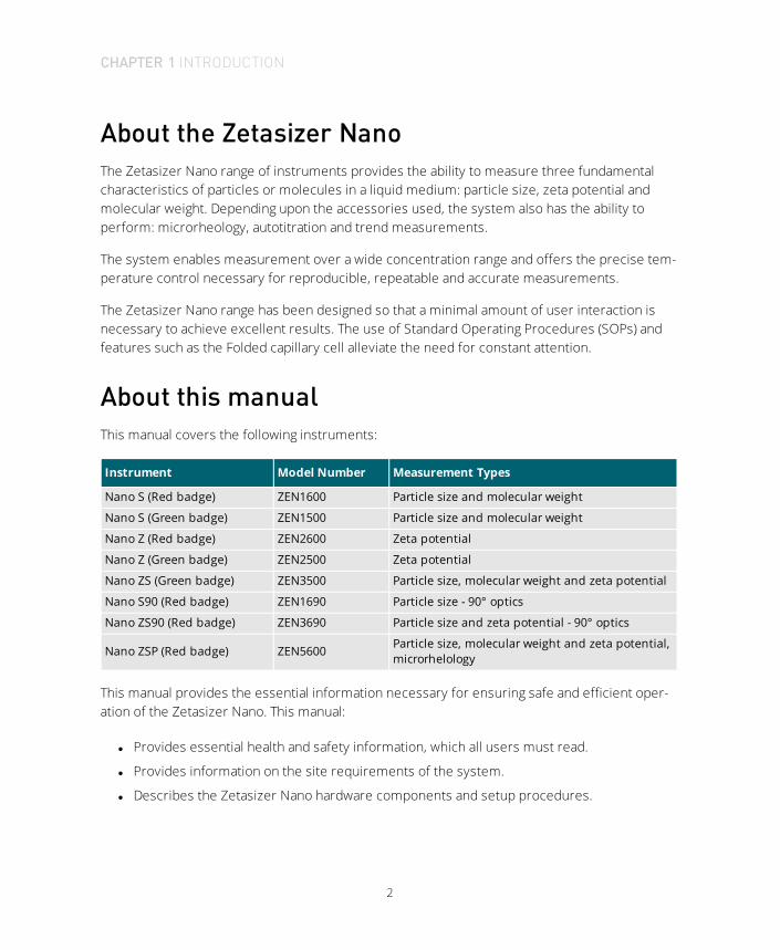
About this manualThis manual covers the following instruments:
Instrument Model Number Measurement Types
Nano S (Red badge) ZEN1600 Particle size and molecular weight
Nano S (Green badge) ZEN1500 Particle size and molecular weight
Nano Z (Red badge) ZEN2600 Zeta potential
Nano Z (Green badge) ZEN2500 Zeta potential
Nano ZS (Green badge) ZEN3500 Particle size, molecular weight and zeta potential
Nano S90 (Red badge) ZEN1690 Particle size - 90° optics
Nano ZS90 (Red badge) ZEN3690 Particle size and zeta potential - 90° optics
Nano ZSP (Red badge) ZEN5600 Particle size, molecular weight and zeta potential,microrhelology
This manual provides the essential information necessary for ensuring safe and efficient oper-ation of the Zetasizer Nano. This manual:
l Provides essential health and safety information, which all users must read.
l Provides information on the site requirements of the system.
l Describes the Zetasizer Nano hardware components and setup procedures.
CHAPTER 1 INTRODUCTION

3
l Provides a brief description of the measurement process.
l Describes the basic maintenance procedures.
l Provides the specifications of the instrument.
Product documentation structureThis manual fits into the following information structure for this product:
l Basic Guide — provides the essentials required to get started, including health and safety.All users must read this manual before using the system.
l User Manual — provides detailed information on how to use the system.
l Accessories Guide — in-depth information about the optional accessories.
l Help system — integrated with the Zetasizer Nano software, provides information on allsoftware features.
Read this manual in conjunction with the main Zetasizer Nano User Manual and the Zetasizer NanoAccessories Guide.
If using the MPT-2 Titrator and Vacuum Degasser, refer to the Titrator and Degasser User Manualwhere necessary.
!WARNING!The instrument and the samples measured may be hazardous if misused. Users mustread the Health and Safety information in this guide before operating this system.
Zetasizer Nano range optionsThe Zetasizer Nano series of particle analyzers consists of a range of different instrument mod-els fitted with a choice of ‘red’ or ‘green’ lasers. The models and their measurement spe-cifications are described in the table below. For details on the accessory options, see theZetasizer Nano Accessories Guide.
CHAPTER 1 INTRODUCTION

4
ZetasizerNano
Size rangemaximum(diameter)
Size range for Zeta poten-tial (diameter)
Molecular weight range(Daltons)
S 0.3 nm to 10 µm - 342 Da to 2x10⁷ Da
Z - 3.8 nm to 100 μm -
ZS 0.3 nm to 10 μm 3.8 nm to 100 μm 342 Da to 2x10⁷ Da
S90 0.3 nm to 5 μm - 342 Da to 2x10⁷ Da
ZS90 0.3 nm to 5 μm 3.8 nm to 100 μm 342 Da to 2x10⁷ Da
Nano ZSP 0.3 nm to 10 μm 3.8 nm to 100 μm 342 Da to 2x10⁷ Da
* Compatible but not recommended because of low sensitivity.
The S90 and ZS90 instruments use optics that have a 90° scattering detector angle for size measurements.
A complete list of measurement specifications is included later in this manual.
Laser typeThe laser fitted is identified by the color on the oval badge on the cover.
l Instruments with a black and red badge on the instrument cover either have a 4 mW 632.8nm ‘red’ laser or a 10 mW 632.8 nm ‘red’ laser (Nano ZSP only).
l Instruments with a black and green badge have a 532 nm 'green' laser.
Generally, red lasers are least suitable for blue samples, while green lasers are least suitablefor red samples.
High Temperature instruments have HT on the main instrument label. High Temperature andother build options exist for all the instruments in the table above.
Note:To view the Zetasizer model, serial number, software and firmware version, left-click theNano icon in the right corner of the status bar on the Zetasizer software.
CHAPTER 1 INTRODUCTION

5
Cells and cuvettesA range of cells and cuvettes are available to use with the Zetasizer instrument. The followingtable lists the cells and their application. For more details, see the Zetasizer Nano AccessoriesGuide.
Cell Application
Disposable polystyrene cuvettes – Standard andSmall volume Size and Zeta potential (with dip-cell)
Folded capillary cell Size and Zeta potential
High concentration cell Size and Zeta potential
Quartz glass cuvettes – Square, Standard, Low andUltralow Volume, Flow
Size, Molecular weight and Zeta potential (withdip-cell)
Universal Dip cell Zeta potential
Surface Zeta Potential cell Zeta potential
Access to the instrument
Malvern Panalytical personnelMalvern Panalytical personnel (service engineers and representatives) have full access to theinstrument and are the only people authorized to perform all service procedures that mayrequire the removal of the covers.
!WARNING!Removal of the main covers by unauthorized personnel, even a supervisor, will void thewarranty of the instrument.
SupervisorThe supervisor is responsible for the management and safety of the instrument and its oper-ation. The supervisor also trains the operators and can perform user maintenance routines.
CHAPTER 1 INTRODUCTION

6
OperatorAn operator is a person trained in the use of the system. The operator can perform some usermaintenance routines identified.
!WARNING!Failure to follow these guidelines could result in exposure to hazardous voltages and laserradiation.
Assumed information
GeneralThe Zetasizer Nano can be used with a variety of Zetasizer Nano accessories that allow it tomeasure a variety of samples. The basic function of these is to prepare and deliver the sampleto the optical unit for measurement.
For more details of any accessory, refer to the Zetasizer Nano Accessories Guide.
Naming conventionWithin this manual:
l The Zetasizer Nano is referred to as “the optical unit” or “the instrument.”
l The accessories are referred to directly, for example as the “MPT-2 Titrator,” “the VacuumDegasser,” or as “the accessory”
l The combination of the optical unit, one or more accessories, and the computer isreferred to as “the system.”
Menu commandsSoftware menu commands are referred to in the form main menu-menu item. As an example,the command Configure-New SOP refers to selecting the New SOP item in the Configure menu.Menu commands are shown in bold text.
CHAPTER 1 INTRODUCTION

7
Where to get helpThis section provides information on how to get help with your system.
Help deskAll queries regarding the system should initially be directed to your local Malvern Panalytical rep-resentative, providing the following information:
l Model and serial number of the instrument. The serial number is shown on the Zetasizersoftware status bar — roll over the Nano icon to display.
l The software version. To find this, select Help-About in the software. Alternatively, movethe mouse over the instrument status bar icon. The Application Version is the main firm-ware version number to note.
Contact the International Helpdesk if the local Malvern Panalytical representative is not avail-able:
Telephone: +44 (0) 1684 891800 or email: [email protected].
If located in the United States, contact the United States Helpdesk if the local Malvern Pana-lytical representative is not available:
Telephone: 1 508 768 6450 or email: [email protected].
Note: The help lines are primarily English speaking.
Remote supportMalvern Panalytical offers a remote support service, delivered by an Internet connection. Bene-fits include fast and efficient fault diagnosis and reduced downtime and costs.
CHAPTER 1 INTRODUCTION

8
www.malvernpanalytical.comThe Malvern Panalytical website offers a comprehensive range of resources for customer use24 hours a day, 7 days a week.
CHAPTER 1 INTRODUCTION

CHAPTER 2 HEALTH AND SAFETY
General safety issues 10
General maintenance warnings 17
Optical unit warnings 18
Sample handling warnings 18
Fumes 19
9

10
General safety issues
!WARNING!Use of the system in a manner not specified by Malvern Panalytical may impair the pro-tection provided by the system.
Site requirementsThe system has specific site requirements that must be enforced to ensure safe operation ofthe instrument. Refer to Site requirements on page 21.
Positioning the instrument
!WARNING!Do not position the instrument such that the power cord, where it exits the product, isunreachable for disconnection.
!WARNING!Do not obstruct the ventilation slots underneath the instrument or the fans on the rearpanel. Restricting airflow can damage the instrument or cause overheating.
Purge warnings (MPT-2 Titrator)
!
WARNING!
l If a Nitrogen supply is used, the system must be located in a well ventilated envir-onment.
l Turn off the supply when not in use.
CHAPTER 2 HEALTH AND SAFETY

11
Temperature warnings
WARNING!The warning triangles on the cuvette lid and thermal cap warn of potentially hazardoustemperatures within the cell area. The temperature range of the cell area is 2 °C to 90 °Cfor the standard instrument, 2 °C to 120 °C for the High Temperature option.
Laser safety warningsThe Zetasizer Nano optical unit is a Class 1 laser product and, as such, there is no exposure tolaser radiation in its normal operation. The laser passes through the cell area but this area isenclosed when the cell is fitted. When the cell area lid is open, a mechanical laser shutter pre-vents exposure to laser radiation.
!WARNING!Use of controls or adjustments or performance of procedures other than those specifiedherein may result in hazardous radiation exposure.
The following diagram shows the location of the laser warning labels and the table below liststhe specfications:
CHAPTER 2 HEALTH AND SAFETY

12
CLASS 1
LASER PRODUCT
CAUTIONLASER RADIATION WHEN OPEN
AVOID DIRECT EYE EXPOSURE
CLASS 1
LASER PRODUCT
CAUTION - CLASS 3R LASER
RADIATION WHEN OPEN
AVOID DIRECT EYE EXPOSURE
CAUTION - CLASS 3B LASER
RADIATION WHEN OPEN
AVOID EXPOSURE TO BEAM
1 2
1. 532 nm 'Green' laser (Class 3B) (Nano S, S90) and 633 nm 'Red' laser (Class 3B) (Nano ZSP)
2. 633 nm 'Red' laser (Class 3R) (Nano Z, S, ZS, S90, ZS90)
Item Specification
Zetasizer Nano Z, S, ZS, S90, ZS90 specification for 'Red' laser
Light source He-Ne Laser
Power Internal laser maximum output of less than 4 mW (CW)
Beam wavelength 632.8 nm
Zetasizer Nano S, S90 specification for 'Green' laser
Light source Frequency doubled DPSS Nd:YAG Laser
Power 50 mW
Beam wavelength 532 nm
Zetasizer Nano ZSP specification laser
Light source He-Ne Laser
Power 10 mW
Beam wavelength 633 nm
CHAPTER 2 HEALTH AND SAFETY

13
Electrical safety warningsTake care when measuring samples not to spill liquid or powder over the system covers. Con-ducting materials or liquids can damage insulation and cause dangerous conditions. If a spillageoccurs, disconnect the power and carefully clean up before re-applying power to the system.Users who suspect powder or liquid has entered the covers should call a Malvern Panalyticalrepresentative to arrange a service call.
!WARNING!Never attempt to remove the covers; always contact a Malvern Panalytical representative.
PAT testing
If PAT testing is required, connect the earth lead to the appropriate earth stud. Malvern Pana-lytical recommends that the product is PAT tested annually, or if it is suspected that its electricalsafety has been compromised.
Power cords and power safetyThe notes in this section indicate best practice. Follow these when connecting the instrument tothe power supply unit.
!WARNING!Only operate this product with the power supply unit provided with the instrument.
Power cord set requirements
Power cords must meet the requirements of the country where the product is used. For fur-ther information contact your Malvern Panalytical representative.
General requirements
The requirements listed below are applicable to all countries:
CHAPTER 2 HEALTH AND SAFETY

14
l The power cord must be approved by an acceptable accredited agency responsible forevaluation in the country where the power cord set will be installed.
l The power cord set must have a minimum current capacity of 10A (7A in Japan only) and anominal voltage rating of 125 or 250 volts AC, as required by each country's power sys-tem.
l The area of the wire must be a minimum of 0.75 mm2 or 18 AWG, and the length of thecord must be less than 3 m.
l The power cord must be routed to avoid: being walked on, pinched by items placed uponit or against it, or made wet. Pay particular attention to the plug, the electrical outlet, andthe point where the cord exits the product.
!WARNING!Do not operate this product with a damaged power cord set. If the power cord set is dam-aged in any manner, replace it immediately.
!WARNING!Do not use the power cord received with this product on any other products.
Power safety information
The following notes indicate guidelines to follow when connecting the Malvern Panalytical powersupply using single and multiple extension leads, connection via AC Adapters and use of Unin-terruptible Power Supplies (UPS).
!
WARNING!To prevent electric shock, plug the instrument or accessory into correctly earthed elec-trical outlets. Never use the system without a properly connected protective earth con-ductor.
The power cord supplied is equipped with a grounding connection to ensure grounding integrityis maintained.
CHAPTER 2 HEALTH AND SAFETY

15
Advice on use of extension leads
Follow this advice when using single or multiple socket extension leads. These are also calledtrailing sockets.
l Ensure the lead is connected to a wall power outlet and not to another extension lead. Theextension lead must be designed for grounding plugs and plugged into a grounded wall out-let.
l Ensure that the total ampere rating of the products being plugged into the extension leaddoes not exceed the ampere rating of the extension lead.
l Use caution when plugging a power cord into a multiple socket extension lead. Someextension leads may allow a plug to be inserted incorrectly.
l Incorrect insertion of the power plug could result in permanent damage to the instrumentor accessory, as well as risk of electric shock and/or fire. Ensure that the ground con-nection (prong/pin) of the power cord plug is inserted into the mating ground contact ofthe extension lead
Advice on use of AC adapters
!WARNING!Do not use adapter plugs that bypass the grounding feature, or remove the grounding fea-ture from the plug or adapter.
l Place the AC adapter in a ventilated area, such as a desk top or on the floor.
l The AC adapter may become hot during normal operation of the instrument or accessory.Use care handling the adapter during or immediately after operation.
l Use only the Malvern-provided AC adapter approved for use with the instrument and/oraccessory. Use of another AC adapter may cause a fire or explosion.
Advice on use of Uninterruptible Power Supplies (UPS)
To help protect the instrument and/or accessory from sudden, transient increases anddecreases in electrical power, use a surge suppressor, line conditioner or UPS.
CHAPTER 2 HEALTH AND SAFETY

16
Moving the systemFollow the guidelines in this section if it is necessary to move the system.
Moving the optical unit
l Disconnect the computer and power supply before attempting to move the system.
l Always lift the instrument by holding it under both of its short sides, with a firm grip on themetal base plate. Never lift an instrument by its covers:
!WARNING!The optical unit weights 20 kg. Adopt proper lifting techniques to avoid back injury.
l If moving the instrument large distances, Malvern Panalytical recommends repacking theinstrument in its original packaging.
CHAPTER 2 HEALTH AND SAFETY

17
Moving accessories
If it is necessary to move the accessories, follow these guidelines:
l Disconnect the power supply before attempting to move the accessory.
l Disconnect and drain or vent any tubing that carries fluid or compressed air, includingsample tubing, before moving the accessory.
l Lift the accessory by holding it under the base.
!WARNING!The Titrator weighs 5.3 kg and the Vacuum Degasser dispersion unit weights 2.75 kg.Adopt proper lifting techniques to avoid back injury.
l If moving the accessory large distances, Malvern Panalytical recommends repacking theunit in its original packaging.
General maintenance warnings
!WARNING!Before performing any maintenance operation, read and observe all safety warnings listedin this chapter.
!
WARNING!The system contains no internal serviceable parts. Never attempt to remove the covers ofthe optical unit or an accessory. Removal of the covers voids the warranty andmay exposethe user to dangerous laser radiation.
!
WARNING!Failure to follow these guidelines could result in the emission of laser radiation or expos-ure to hazardous voltages. Laser radiation can be harmful to the body and can cause per-manent eye damage. The Zetasizer Nano accessory units do not contain a laser but areconnected to the optical unit that does.
CHAPTER 2 HEALTH AND SAFETY

18
Optical unit warnings
!WARNING!Before cleaning, always disconnect the unit from the power supply and computer and dis-connect all electrical cables. Ensure the unit is completely dry before re-applying power.
Sample handling warningsl Always handle all substances in accordance with the COSHH (Control Of Substances Haz-
ardous to Health) regulations (UK) or any local regulations concerning sample handlingsafety.
l Before using any substance, check the Safety Data Sheets for safe handling information.
l Use the instrument in a well ventilated room, or preferably within a fume cupboard, if thefumes from the sample or dispersant are toxic or noxious.
l Wear personal protective equipment as recommended by the Material Safety Data Sheetsif toxic or hazardous samples are being handled, particularly during sample preparationand measurement.
l Wear protective gloves when handling hazardous materials, or those that cause skin infec-tions or irritations.
l Do not smoke during measurement procedures, particularly where inflammable samplesare used or stored.
l Do not eat or drink during measurement procedures, particularly where hazardoussamples are used or stored.
l Take care when handling glass (e.g. microscope slides and beakers). Hazardous materialsmay enter a wound caused by broken glass.
l Always test a new sample or dispersant for chemical compatibility before use.
l After measuring hazardous samples, carefully clean the system to remove any con-taminants before making another measurement.
l Always label samples for analysis using industry standard labeling, particularly if they arehandled by a number of staff or stored for long periods. Clearly mark any operator hazardand associated safety precautions that are required for the handling of dangerous mater-ials.
CHAPTER 2 HEALTH AND SAFETY
19
l Keep a record of all hazardous substances used in the system for protection of serviceand maintenance personnel.
l Always adopt responsible procedures for the disposal of waste samples. Most local lawsforbid the disposal of many chemicals in such a manner as to allow their entry into thewater system. The user is advised to seek local advice as to the means available for dis-posal of chemical wastes in the area of use. Refer to the Safety Data Sheets.
l The surfaces of the system may be permanently damaged if samples are spilled on them.If a spillage does occur, disconnect the system from the power supply before scru-pulously cleaning up the spillage.
Fumes
!WARNING!Use the system in a fume cupboard if using dispersants that emit hazardous fumes. Con-sult Malvern Panalytical before using dispersants with ignitable vapor.
CHAPTER 2 HEALTH AND SAFETY


CHAPTER 3 SITE REQUIREMENTS
Environmental conditions 22
Space required 23
MPT-2 titrator services 24
Computer specification 24
21

22
Environmental conditionsThe site must be:
l Away from strong light sources (such as windows)
l Away form strong heat sources (such as radiators)
l Well ventilated (for noxious samples)
l On a horizontal vibration-free bench built to support the weight of the system (shownbelow):
Unit Weight
Zetasizer Nano 20 kg
MPT-2 Titrator 5.3 kg
Vacuum Degasser 2.75 kg
Store and operate the system in the following conditions (accurate measurements are sample-dependent, for example dry powders may stick together in high humidity):
Condition Requirement
IP rating Designed to meet IP41B
Operational conditions 5 °C to 40 °C (41 °F to 104 °F)
Storage conditions -20 °C to 50 °C (-4 °F to 122 °F)
Humidity Maximum humidity 80% for temperatures up to 31 °C, decreasing linearlyto 50% relative humidity at 40 °C.
Altitude Up to 2000 m
Mains supply voltagefluctuations Up to ± 10% of nominal voltage
Overvoltage category II (IEC 60664)
Pollution degree 2 (BS EN 60664-1:2003)
Installation category II (BS EN 60664-1:2003)
l Do not obstruct power sockets - they may need to be disconnected in an emergency.
l Do not pass electrical cables through areas where liquids can be spilled.
CHAPTER 3 SITE REQUIREMENTS

23
Space requiredProvide enough space to allow easy access to all components and connections. Allow at least800 mm above the bench surface for access to the cell area and accessories. The followingtable lists the component dimensions.
Note:The height listed is with the cuvette holder closed.
Component Width Depth Height
Zetasizer Nano 320 mm 622 mm 260 mm
MTP-2 Titrator 170 mm 390 mm 260 mm
Vacuum Degasser 75 mm 250 mm 130 mm
Computer and printer See manufacturer's documentation
The following diagram shows the minimum recommended space required for a typical systemusing an MPT-2 Titrator, and its computer.
300 mm
150 m
m
150 mm
300 mm1240 mm
750
mm
800 mm
(maximum)
CHAPTER 3 SITE REQUIREMENTS

24
MPT-2 titrator services
Nitrogen purge specification
!WARNING!A Nitrogen supply must be used in a well ventilated environment.
The MPT-2 Titrator has a purge connector for connection of a Nitrogen purge supply. This can beused to blanket the area directly above the sample and prevent any absorption of Oxygen thatmay change the pH characteristics of the sample, for example, cause a pH drift.
If a Nitrogen supply is required, it must conform to the following specifications:
l The Nitrogen supply must be dry, free from oil, and filtered to remove any contaminantsthat could affect the sample.
l The flow rate should be adjustable between 2 and 20 ml/min.
Computer specificationContact the Malvern Panalytical Helpdesk or website for the recommended computer spe-cification. This is also provided in the Software Update Notification.
CHAPTER 3 SITE REQUIREMENTS

CHAPTER 4 SYSTEM OVERVIEW
Overview 26
Optical unit 28
Connecting the Zetasizer Nano 34
25
26
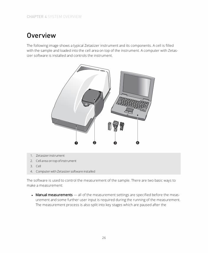
OverviewThe following image shows a typical Zetasizer instrument and its components. A cell is filledwith the sample and loaded into the cell area on top of the instrument. A computer with Zetas-izer software is installed and controls the instrument.
1 2 3 4
1. Zetasizer instrument
2. Cell area on top of instrument
3. Cell
4. Computer with Zetasizer software installed
The software is used to control the measurement of the sample. There are two basic ways tomake a measurement:
l Manual measurements — all of the measurement settings are specified before the meas-urement and some further user input is required during the running of the measurement.The measurement process is also split into key stages which are paused after the
CHAPTER 4 SYSTEM OVERVIEW

27
completion of each stage.
Manual measurements tend to be used for one-off measurements or as part of a methoddevelopment, for example, establishing the optimal settings for measuring the sampleand then saving into a SOP file.
l Standard Operating Procedure (SOP) measurements — most of the measurement set-tings are stored within a SOP file which has been previously created by the user. Once aSOP has been initiated, the measurement sequence requires less user intervention thana manual measurement.
As SOPs lock-down most of the measurement settings, they improve consistency andprovide greater repeatability; features that are important in quality controlled envir-onments.
For a full description of the hardware and software in the Zetasizer Nano system, see the fol-lowing manuals:
l Zetasizer Nano User Manual
l Zetasizer Nano Accessories Guide
l MPT-2 Titrator and Degasser Manual
CHAPTER 4 SYSTEM OVERVIEW
28
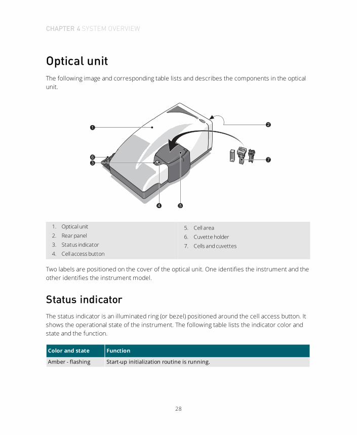
Optical unitThe following image and corresponding table lists and describes the components in the opticalunit.
2
7
4 5
1
3
6
1. Optical unit
2. Rear panel
3. Status indicator
4. Cell access button
5. Cell area
6. Cuvette holder
7. Cells and cuvettes
Two labels are positioned on the cover of the optical unit. One identifies the instrument and theother identifies the instrument model.
Status indicatorThe status indicator is an illuminated ring (or bezel) positioned around the cell access button. Itshows the operational state of the instrument. The following table lists the indicator color andstate and the function.
Color and state Function
Amber - flashing Start-up initialization routine is running.
CHAPTER 4 SYSTEM OVERVIEW

29
Color and state Function
Amber “Standby”. Instrument is functioning correctly but is either not connected tothe computer or the software has not been started.
Green Instrument is functioning correctly and is ready to start a measurement.
Green - flashing Instrument is performing a measurement.
Red Instrument has detected an error. The measurement will be stopped.
Cell access buttonThe cell access button is positioned in the middle of the status indicator. Press the cell accessbutton to open the cell area lid.
Cell area
WARNING!The system is capable of heating the cell to high temperatures. Care should be takenwhen removing the cells if a measurement has been performed at high temperatures. Itis recommended that the cell area is allowed to cool before removing the cell.
The cell area is where all cells are inserted to undertake a measurement. The cell area is com-pletely self-enclosed and controls the sample temperature over the range 0 °C to 90 °C (up to120 °C for high temperature instruments).
For more information about the cell area, see the Zetasizer Nano User Manual.
CHAPTER 4 SYSTEM OVERVIEW

30
The following image lists the components in the cell area of the optical unit.
1
2
3
4
5
6
7
8
1. Electrodes
2. Cell area lid
3. Thermal cap
4. Drain channel
5. Cell basin
6. Access channel for Titrator and flow cell tibes
7. Cell clamp
8. Drain port
CHAPTER 4 SYSTEM OVERVIEW

31
Cuvette holderThe cuvette holder swings out from the instrument and is used for storing the up to 12 cellsbefore and after use.
For more information on the cuvette holder, see the Zetasizer Nano User Manual.
CHAPTER 4 SYSTEM OVERVIEW

32
Rear panelThe rear panel provides all the connections. The following image and corresponding table listsand describes the components on the rear panel.
!WARNING!Do not obstruct the ventilation slots underneath the instrument or the cooling fans on therear panel.
1 2 3 4 5 6 7 8
9 10 11 12 13
1. Power switch
2. Fuse holder
3. Power input socket
4. Cooling fan
5. Flow-made connection
6. Accessory connections
7. Accessory input
8. Mod record
9. Cooling fan
10. Purge connection
11. Green laser power supply unit input
12. Computer connection
13. Serial number and model number label
CHAPTER 4 SYSTEM OVERVIEW

33
Details about connections
The following table lists and describes details about the connections on the rear panel of theoptical unit, the main component of the Zetasizer Nano system.
Real panelcomponent Description
Power input socket Mains power input socket for the instrument.
Fuse holder Fuse for the instrument. For details on replacing the fuse, see Replacing the sys-tem fuse on page 61
Power switch The on/off power switch for the instrument.
Computer con-nection The USB cable from the computer is connected here.
Accessoryconnections
Two types of connections are available:
l CAN Ports. Use these ports to connect any Malvern Panalytical supported accessory that requires a CAN connection (Controller Area Network).
l RS232 Ports. Use these ports to connect any Malvern Panalytical supplied accessory that requires an RS232 connection.
Accessories are controlled using the Zetasizer software. Consult the respective accessory manual for details.
Cooling fans In conjunction with ventilation slots underneath the instrument, the fansprovide cooling to the internal components of the Zetasizer.
Serial number andmodel numberlabel
Identifies the actual Zetasizer Nano model and its serial number. Please quoteall numbers in any correspondence with Malvern Panalytical.
Mod record Indicates any instrument updates. This is used for reference by the MalvernPanalytical service personnel.
Accessory outputA 12V output supply is provided on the rear panel to connect to any MalvernPanalytical supplied accessory that requires an external voltage source. Consultthe respective accessory manual for details.
Green laser PSUinput
If the instrument uses a 532 nm ‘green’ laser, connect the laser PSU to this con-nection.
Purge connection Used to connect a dry-air supply for use in humid climates. For more informationabout the purge connection, see MPT-2 titrator services on page 24
Flow-modeconnection
This connection is used when inputting a signal from an external measuringsource, such as an Ultra-violet absorption detector or Refractive index detector to
CHAPTER 4 SYSTEM OVERVIEW

34
Real panelcomponent Description
the Zetasizer Nano. A real-time parameter reading from the device can be dir-ectly inputted into the Nano optics unit and added to the Nano sample record.
The Connector input voltage specification is: -5V to +5V (analogue).
Connecting the Zetasizer NanoThis section describes how to install the system for initial system setup.
Installing the systemThe following image and table below list and describe the connections for installing theZetasizer Nano.
1
2 3 4
5 6 7
1. Computer with Zetasizer software
2. Power cable connection
3. Input signal cable connection
4. Accessory connections
5. Purge air port
6. Laser power supply unit input
7. USB input connection
Perform the following steps to install the Zetasizer Nano:
CHAPTER 4 SYSTEM OVERVIEW

35
1. Connect the USB cable to the connector marked USB on the rear panel of the ZetasizerNano.
2. Connect the other end of the cable to the USB connection on the computer.
3. Connect the power cable to the power socket on the rear panel of the instrument.
!WARNING!This product must be connected to a protective earth.
4. Make all of the computer connections (mouse, keyboard, power, and so on) by followingthe instructions provided with the computer.
5. Install the following options as required:
l If purge air is required, connect it to the purge air port at the base of the rear panel.
l If the instrument is fitted with the 532 nm 'green' laser option, connect the laser powersupply unit to the power supply unit input on the rear panel.
l If accessories are used, connect those to the appropriate ports as described in their per-spective user manuals.
l If the instrument is connected to an external detector, and the flow-mode facility is used,connect the input signal cable to the input signal connection.
CHAPTER 4 SYSTEM OVERVIEW

CHAPTER 5 SOFTWARE OVERVIEW
Zetasizer software 38
Measurement display 40
Menu bar 42
Installing the software 42
37
38
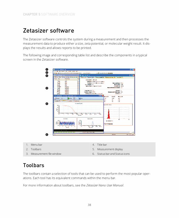
Zetasizer softwareThe Zetasizer software controls the system during a measurement and then processes themeasurement data to produce either a size, zeta potential, or molecular weight result. It dis-plays the results and allows reports to be printed.
The following image and corresponding table list and describe the components in a typicalscreen in the Zetasizer software.
1
2
3
5
4
6
1. Menu bar
2. Toolbars
3. Measurement file window
4. Title bar
5. Measurement display
6. Status bar and Status icons
ToolbarsThe toolbars contain a selection of tools that can be used to perform the most popular oper-ations. Each tool has its equivalent commands within the menu bar.
For more information about toolbars, see the Zetasizer Nano User Manual.
CHAPTER 5 SOFTWARE OVERVIEW

39
Measurement file windowThe Measurement file window displays all the information for a single measurement file. Youcan display more than one measurement file window at a time. The contents of the windowchanges when a Record or Report tab is selected.
The Measurement file window contains the following:
l Measurement file workspace
When performing zeta potential measurements, it may be unnecessary to see para-meters associated with size measurements in the measurement file window. A meas-urement file workspace called zeta potential is available that displays only parametersassociated with zeta potential measurements.
CHAPTER 5 SOFTWARE OVERVIEW

40
Measurement displayThe Measurement display shows the progress of the measurement as the measurement isbeing performed. The screen display shown changes depending on the type of measurementbeing performed and the view tab selected.
1. Button bar
2. Tab views
3. Status bar
4. Progress meter
Button barThe button bar provides the controls for the measurement operation.
Button Action
Settings Open the measurement settings window. You can add extra comments and changesto the measurement parameters prior to the measurement being started.
Start/StopStart and stop the measurement. If you click the Stop during a measurement, it mustbe started again from the beginning. Stop does not act like pause - you are asked ifyou wish to abort the measurement.
Help Open the Help file.
Accessory Open the MPT-2 Titrator Manual control window. Click the Start to close the manual
CHAPTER 5 SOFTWARE OVERVIEW

41
Button Action
window.
Eject Zetasizer APS instrument only.
Tab viewsThe Tab views enable the progress and results of the measurement to be viewed. The first tabshows the results, and will change with respect to the measurement type and results viewselected. In the previous example, this tab is labelled Intensity PSD to identify that intensity res-ults are being viewed. This tab shows different graph plots relevant to the measurement typeselected. The other three tabs windows — Multi-view, Log sheet and Expert advice — are stand-ard for each Measurement type.
l The views displayed in the first (result) tab, can be altered by right-clicking on the graphand selecting from the list displayed. A graph only, or a graph with a summary table will beshown depending upon the view chosen. The Result tab is named after the result viewchosen.
l The Multi-view tab displays the results in three smaller windows. As with the first (result)tab, the view in each separate window can be altered by right-clicking in the window andselecting a different view from the list displayed. The size of each window can altered bymoving the borders around.
Status bar and Status iconsThe status bar provides an indication of the instrument’s current operating state and an exten-ded description of the tool icons. If required, use the View-Toolbars-Customize menu item todisable it.
The right portion of the status bar includes icons to indicate which instrument is connected andany additional features that are installed.
Progress meterThe progress meter shows how far the measurement has progressed plus the number of meas-urements performed and the measurement runs completed. Also shown are the temperature,measurement position, and attenuator settings.
CHAPTER 5 SOFTWARE OVERVIEW

42
Menu barThe menu bar contains the main menu headings for all software functions.
Menu name Description
File Use the Filemenu to either create a NewMeasurement or SOP file, or to openan existing Measurement or SOP file.
EditUse the Edit menu to move and manipulate records in the Measurement filewindow(s). You can cut, copy, paste, and delete records into their own meas-urement file or into other measurement files.
View Use the Viewmenu to select which reports to display in the measurement filewindow and which Toolbars to display.
MeasureSelect theMeasuremenu when ready to perform a measurement. Choose to useeither an existing measurement SOP (Measure-StartSOP...) or manually set upthe measurement and sample details (Measure-Manual).
Tools Use the Toolsmenu to aid in the measurement, display, and reporting func-tions of the software.
Security Use the Securitymenu to configure the software to limit each user's access tovarious functions, and to prevent unauthorized changes.
WindowUse this menu to alter the view characteristics of any measurement file windowsthat are open. You can minimize, tile, and cascade the measurement file win-dows.
Help Use the Help menu to access the help topics.
For more details about each menu, see the Zetasizer Nano User Manual.
Installing the softwareIf, at some point in the future, the computer used with the instrument is changed, you mustinstall the software on the new computer. Consult the software update notification suppliedwith the software.
Perform the following steps to install the software:
CHAPTER 5 SOFTWARE OVERVIEW

43
1. Insert the Zetasizer software CD into the CD drive.
2. If Autorun is enabled on the computer, the software starts to install automatically. Followall on-screen instructions to complete the installation.
3. If Autorun is not enabled, select Start-Run-Setup and follow the on-screen instructions.
Note:If the software is subsequently updated with a new version, any custom reports, para-meter settings and SOPs are preserved.
CHAPTER 5 SOFTWARE OVERVIEW


CHAPTER 6 QUICK START: USINGTHE SYSTEM
Turning on the system 46
Running the installation test macro 47
Running a SOP 56
45

46
Turning on the systemIf it is not already switched on, perform the following steps to turn on the Zetasizer Nano andstart the Zetasizer software:
1. Close the lid and turn on the optical unit, switch on power at the power socket, and turnthe power switch on at the rear of the unit.
A beep sounds to indicate the instrument has been turned on and the initialization routinewill begin, followed by a second beep once the instrument has finished the routine. Twofurther beeps indicate the instrument has reached the default temperature of 25 °C.
2. If it is not already switched on, turn on the computer.
3. Do either of the following:
a. Click the Zetasizer Software icon on the desktop:
b. Click the Start menu and select Malvern Panalytical and then select Zetasizer Software.
4. Allow the instrument to power up for at least 30 minutes before you begin making meas-urements.
Note:All laser basedmeasuring instruments should be powered up for approximately 30minutes before making measurements. This is to prevent any thermal equilibrationproblems affecting the measurement results.
CHAPTER 6 QUICK START: USING THE SYSTEM

47
Running the installation test macroThe Zetasizer Nano system includes an installation test macro and the Zeta potential standard.
The installation test macro allows you to perform a Sizing and a Zeta measurement to runthrough the processes involved with preparing a sample, running a measurement, and also toensure the system is performing properly.
Perform the following steps to unpack the Zeta standard and to run the installation test macro:
1. Unpack the Zeta potential transfer standard.
Note: Once unpacked, store the zeta potential transfer standard in a refrigerator at a tem-perature range of 4 - 8 °C. If the standard is stored outside this range, it could give inac-curate test responses.
2. Start the Zetasizer Nano software.
3. Once the software has started, select Tools-Macros-Installation Test, as shown:
CHAPTER 6 QUICK START: USING THE SYSTEM

48
Note:The results are saved to a measurement file named Installation Test.dts whichopens automatically.
4. The instrument reports what it is going to test: size, zeta potential or both, as shownbelow.
Tip:The type of test(s) performed depends on the instrument's specification – S: size, Z:zeta potential and ZS or ZS90: both zeta potential and size.
5. Click OK to start the test.
Performing the Size testPerform the following steps to run the Size test:
1. Remove the square plastic cuvette (not the glass one) from the consumables pack.
2. Fill the cuvette with between 1.0 mL and 1.5 mL of the supplied Zeta potential transferstandard from the syringe as follows:
CHAPTER 6 QUICK START: USING THE SYSTEM
49
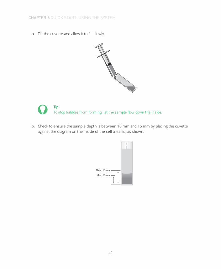
a. Tilt the cuvette and allow it to fill slowly.
Tip:To stop bubbles from forming, let the sample flow down the inside.
b. Check to ensure the sample depth is between 10 mm and 15 mm by placing the cuvetteagainst the diagram on the inside of the cell area lid, as shown:
Max: 15mm
Min: 10mm
CHAPTER 6 QUICK START: USING THE SYSTEM

50
3. Push the lid securely onto the cuvette as shown:
Note:Most cuvettes have a triangle or spot mark, as shown below. This mark must facetowards the front of the Zetasizer Nano.
4. Click OK in response to the following prompt:
5. Press the button to open the chamber lid:
CHAPTER 6 QUICK START: USING THE SYSTEM

51
6. Push the cuvette down so that it is firmly located and then push the chamber lid down.
7. See Test results on page 54 to continue.
Performing the Zeta potential test
Cell preparation
It is recommended to flush the cell to ensure cleanliness and reduce risk of bubble formation.The recommended procedure requires two syringes; filtered deionized (DI) water; and ethanolor methanol:
CHAPTER 6 QUICK START: USING THE SYSTEM

52
1. Flush the cell with ethanol to facilitate wetting.
2. Fill one of the syringes with the DI water and place in one of the sample ports on the cell,the empty syringe is placed into the other port.
3. Flush the contents of the full syringe, through the capillary, into the empty syringe, thenflush back.
4. Repeat this process 4 more times before removing the syringes and performing a finalflush with the dispersant being used for the measurement.
After this, the cell is ready for use. Never attempt to clean the optical surface of the folded capil-lary cell as this will cause small surface scratches that will give inaccurate results.
Zeta potential test
Perform the following steps to run the Zeta potential test:
Load the appropriate cell in the instrument, following the procedures below, then click OK.
1. Clean the cell according to the cell preparation steps above.
2. Press the button to open the measurement chamber:
3. Fill the cell according to the cell type below:
CHAPTER 6 QUICK START: USING THE SYSTEM

53
DTS1070 cell:
4. After inserting the respective cell into the cell holder until it stops, close the meas-urement lid as shown:
CHAPTER 6 QUICK START: USING THE SYSTEM

54
5. See Test results below to continue.
Test resultsThe Size and Zeta potential tests each take approximately six minutes to run.
After a two-minute equilibration period, the software shows the test running, as shown:
When the test finishes, the system displays a prompt indicating if the test passed or failed.
CHAPTER 6 QUICK START: USING THE SYSTEM
55
Note:Test results are stored as a record in the measurement file Installation test.dts.
Passing the tests
If the performed test or tests pass, it indicates that the system is set up correctly.
If testing both the size and the Zeta potential test, the system first runs the Size test and thenprompts for the Zeta capillary cell for the Zeta potential test. If both tests pass, it indicates thatthe system is set up correctly.
Failed tests
If a failure message is displayed for either test type, you will need to re-run both tests. Performthe following steps to repeat the measurement:
1. Insert a new sample in a new cuvette/cell and measure it, ensuring that:l The correct cell type is used.
l The measurement chamber lid is closed properly.
l There are no bubbles in the sample.
l The cell is clean and free from fingerprints, grease, and dust.
2. If rerunning the Size test, perform the following steps (refer to Performing the Size teston page 48 for more details):
l Check that between 1.0 mL and 1.5 mL is injected into the cuvette (giving a sampledepth of 10 mm to 15 mm).
l Check that the triangle on the cuvette faces forward.
3. If rerunning the Zeta potential test, perform the following steps:
l Wet another cell thoroughly using ethanol or methanol as described in Performingthe Zeta potential test on page 51 and then check that there are no scratches on it.Wipe it dry with a lint-free cloth (Malvern Panalytical recommends camera lens clean-ing pads).
CHAPTER 6 QUICK START: USING THE SYSTEM

56
!CAUTION!Do not try to clean the optical area on the front of the “U” part of the cell asthis will cause small scratches which can distort the result.
l Check that the capillary cell is filled.
l Ensure that the cell plugs are inserted firmly.
If the test continues to fail, contact the local Malvern Panalytical representative. For details, seeWhere to get help on page 7.
Running a SOPOnce the instrument is set up and its performance validated with the Zeta transfer standard, itis ready for use. Measurements are made using Standard Operating Procedures (SOPs). Mal-vern Panalytical supplies some default SOPs. Supervisors and advanced users can create addi-tional SOPs.
This is a summary of the procedure only. For more detailed information on the process, includ-ing sample preparation and cell selection, see the Zetasizer Nano User Manual.
Perform the following steps to run a SOP:
1. Close the lid and turn on the instrument. Wait 30 minutes for the laser to stabilize.
2. Start the Zetasizer Nano software.
3. Prepare the samples according to the guidelines given in the Zetasizer Nano User Manual.
4. Choose the cell(s) appropriate for the sample and measurement type. For details on select-ing and preparing the measurement cell, see the Zetasizer Nano Accessories Manual.
5. Fill the cell(s) with the prepared sample.
6. Do the following to make a SOP measurement:a. In the Zetasizer software, select Measure-Start SOP. The list of available SOPs are dis-
played.
b. Select the SOP required and click Open.
c. Follow any on-screen instructions that are displayed. The system displays the Meas-urement display.
CHAPTER 6 QUICK START: USING THE SYSTEM

57
d. When requested, insert the cell into the instrument and wait for the temperature tostabilize.
e. Click Start ( ). The measurement will be made and the results displayed and savedtot he measurement file you selected when you started the SOP.
7. Note the messages in the black status bar (near the base of the window) which shows theprogress of the measurement.
8. When the measurement finished, click the button in the upper right corner of the win-dow to close the window.
For more detailed information, see the Zetasizer Nano User Manual.
CHAPTER 6 QUICK START: USING THE SYSTEM


CHAPTER 7 MAINTENANCE
About maintenance procedures 60
Cleaning cells and accessories 60
Cleaning the covers 60
Replacing the system fuse 61
59

60
About maintenance procedures
Note:Maintenance procedures and details of consumable parts kits for the individual accessor-ies are provided in their respective user manuals.
An operator can perform all procedures except replacing fuses.
Cleaning cells and accessoriesClean cells thoroughly between measurements, especially between different types of sample.Cross-contamination between samples can seriously affect the results.
Refer to the Zetasizer Nano Accessories Guide for information on cleaning and maintaining the celland accessories associated with the Zetasizer Nano instrument.
Cleaning the covers
!
CAUTION!The surfaces of the system may be permanently damaged if samples or dispersants arespilled on them. If a spillage occurs, disconnect the system from the power supply beforecarefully cleaning it up.
Do the following to maintain the covers:
l Periodically clean the covers thoroughly using a mild soap solution.
l Never use excessive liquid for cleaning and always avoid electrical components (such asconnectors) and the cell windows.
l Never use a solvent-based solution for cleaning; it may damage the surface.
CHAPTER 7MAINTENANCE

61
Replacing the system fuse
!WARNING!Fuses must not be replaced by the operator. Only the supervisor or a Malvern Panalyticalrepresentative should attempt to change the fuse.
If the instrument does not power up, check the system fuses. These are in the mains powerswitch on the rear panel.
1. Before changing a fuse, disconnect the instrument from the mains power.
2. Pull the fuse holders out and replace faulty fuses with others of the following spe-cification:
l Rating: T 2A L 250V (T = Time delay)
l Size: 5 mm x 20mm
CHAPTER 7MAINTENANCE


CHAPTER 8 REGULATORYINFORMATION
EU Declaration of Conformity 64
Canadian Regulatory Information (Canada only) 64
VCCI acceptance (Japan only) 64
FCC Notice (US only) 65
Disposal of Electrical & Electronic Equipment 65
63

64
EU Declaration of ConformityThe CE badge on this product signifies conformance to the relevant European Directives — con-sult the Declaration of Conformity certificate for the product for more information.
Canadian Regulatory Information (Canada only)This digital apparatus does not exceed the Class A limits for radio noise emissions from digitalapparatus set out in the Radio Interference Regulations of the Canadian Department of Com-munications.
Note that Canadian Department of Communications (DOC) regulations provide, that changes ormodifications not expressly approved by Malvern Panalytical could void your authority to oper-ate this equipment.
This Class A digital apparatus complies with Canadian ICES-003.
Cet appareil numérique de la classe A est conforme à la norme NMB-003 du Canada.
VCCI acceptance (Japan only)The Voluntary Control Council for Interference (VCCI) mark on this product signifies complianceto Japanese EMC regulations as specified by VCCI.
Translation:
This is a Class A product based on the standard of the Voluntary Control Council for Interferenceby Information Technology Equipment (VCCI). If this equipment is used in a domestic envir-onment, radio interference may occur, in which case the user may be required to take cor-rective actions.
CHAPTER 8 REGULATORY INFORMATION

65
FCC Notice (US only)The Federal Communications Commission (FCC) mark on this product signifies conformance toFCC regulations relating to Radio Frequency Devices. These have been satisfied by testing theproduct against, and being found to be compliant with:
FCC CFR 47 Part 15:October 2011.Class A digital device.
The device complies with part 15 of the FCC Rules. Operation is subject to the following two con-ditions:
1. This device may not cause harmful interference, and
2. This device must accept any interference received, including interference that may causeundesired operation.
Note:This equipment has been tested and found to comply with the limits for a Class A digitaldevice, pursuant to part 15 of the FCC rules. These limits are designed to provide reas-onable protection against harmful interference when the equipment is operated in a com-mercial environment. This equipment generates, uses, and can radiate radio frequencyenergy and, if not installed and used in accordance with the instruction manual, maycause harmful interference to radio communications. Operation of this equipment in aresidential area is likely to cause harmful interference in which case the user will berequired to correct the interference at his own expense.
Note:Changes or modifications not expressly approved by Malvern Panalytical could void theuser’s authority to operate the equipment.
Disposal of Electrical & Electronic EquipmentWhen the need arises to dispose of the system, this should be done in a responsible manner.Follow these guidelines:
CHAPTER 8 REGULATORY INFORMATION

66
l Refer to local regulations on disposal of equipment; in Europe refer to the informationbelow.
l Seek advice from the local Malvern Panalytical representative for details.
l Decontaminate the instrument if hazardous materials have been used in it.
The following is applicable in the European Union and other European countries with separatecollection systems.
This symbol on the product or on its packaging indicates that when thelast user wishes to discard this product it must not be treated as gen-eral waste. Instead it shall be handed over to the appropriate facility forthe recovery and recycling of electrical and electronic equipment.
By not discarding this product along with other household-type waste,the volume of waste sent to incinerators or landfills will be reducedand natural resources will be conserved.
For more detailed information about recycling of this product, pleasecontact your local city office, your waste disposal service, or your Mal-vern Panalytical representative.
CHAPTER 8 REGULATORY INFORMATION

CHAPTER 9 SPECIFICATIONS
Specifications (Optical unit) 68
Chemical compatibility 71
67

68
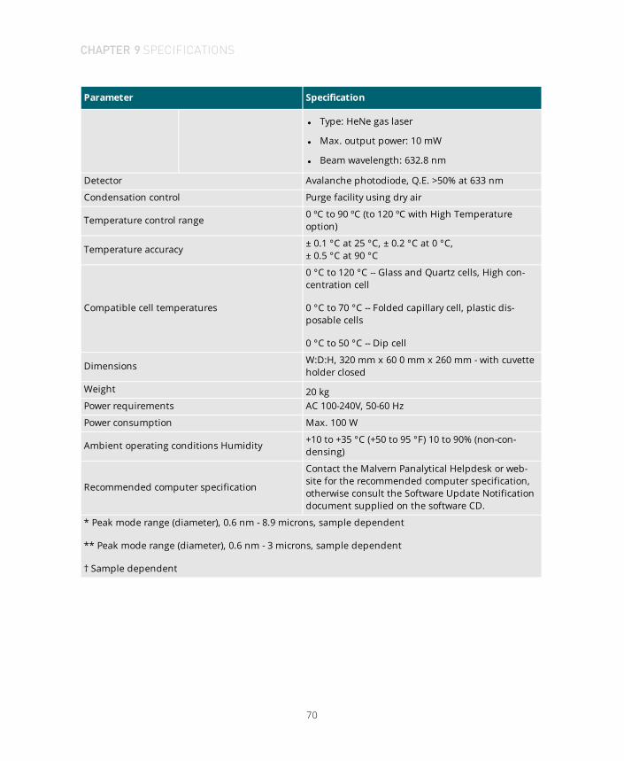
Specifications (Optical unit)The following table lists the specifications of the Zetasizer Nano optical unit. For a complete listof specifications and accessories, refer to the respective user manuals.
All specifications are correct at time of publication, but may be subject to alteration.
Parameter Specification
Size
Nano S, ZS, and ZSP
Range (maximum dia-meter) 0.3 nm - 10 microns *
Minimum sample volume 12 µL
Concentration - minimum 0.1 mg/mL 15 KDa protein
Maximum concentration 40% w/v †
Measurement angles(water as sample dis-persant)
175° (S), 13° and 90° (ZS90)
Nano S90 and ZS90
Range (maximum dia-meter) 0.3 nm - 5 microns **
Minimum sample volume 20 µL
Concentration - minimum 10 mg/mL 15 KDa protein
Maximum concentration Dilute
Measurement angles(water as sample dis-persant)
90° (S90), 13° and 90° (ZS90)
Zeta potential
Sensitivity1 mg/mL 15 KDa protein (ZSP)
10 mg/mL 66 KDa protein (Z, ZS, ZS90)
Zeta potential range > ± 500 mV
Mobility range >± 20 µ.cm/V.s
Maximum sample con-centration 40% w/v †
Minimum sample volume 20 µL (using diffusion barrier)
Maximum sample con-ductivity 200 mS/cm
Conductivity accuracy ± 10%
CHAPTER 9 SPECIFICATIONS

69
Parameter Specification
Molecular weight *
Molecular weight range(estimated from DLS) 1000 Da to 2x10⁷ Da (S, ZS, ZSP, S90, ZS90) †
Molecular weight range
(calculated by Debye plot)
1000 Da to 2x10⁷ Da (S, ZS, ZSP) †
10,000 Da to 2x10⁷ Da (S90 & ZS90) †
Measurement tech-nique
Size:
Nano S, ZS, ZSP Dynamic light scattering (NIBS®)
Nano S90 and ZS90 Dynamic light scattering (90 degrees)
Zeta potential M3-PALS®
Molecular weight Static light scattering
Product laser class Class 1 compliant, IEC 60825-1(1993)+A1(1997)+A2(2001)
Laser attenuation Automatic, transmission 100% to 0.0003%
Laser (Nano S, Z, ZS,Z90, ZS90)
Standard - Red
CDRH and CE compliant (Class llla laser product(CDRH) / Class 3R laser product (IEC60825-1(1993)+A1(1997)+A2(2001))
l Type: HeNe gas laser
l Max. output power: 4 mW
l Beam diameter: 0.63 mm (1/e²)
l Beam divergence: 1.5 mrad
l Beam wavelength: 632.8 nm
Option - Green
CDRH and CE compliant (Class lllB laserproduct(CDRH) / Class 3B laser product (IEC60825-1(1993)+A1(1997)+A2(2001))
l Type: Frequency doubled DPSS Nd:YAG laser
l Max. typical output power: 50 mW
l Beam diameter: 0.32 mm (1/e²)
l Beam divergence: < 2.5 mrad
l Beam wavelength: 532 nm
Laser (Nano ZSP)Standard - Red
CDRH and CE compliant (Class llla laserproduct(CDRH) / Class 3B laser product (IEC60825-1(1993)+A1(1997)+A2(2001))
CHAPTER 9 SPECIFICATIONS
70
Parameter Specification
l Type: HeNe gas laser
l Max. output power: 10 mW
l Beam wavelength: 632.8 nm
Detector Avalanche photodiode, Q.E. >50% at 633 nm
Condensation control Purge facility using dry air
Temperature control range 0 ºC to 90 ºC (to 120 ºC with High Temperatureoption)
Temperature accuracy ± 0.1 °C at 25 °C, ± 0.2 °C at 0 °C,± 0.5 °C at 90 °C
Compatible cell temperatures
0 °C to 120 °C -- Glass and Quartz cells, High con-centration cell
0 °C to 70 °C -- Folded capillary cell, plastic dis-posable cells
0 °C to 50 °C -- Dip cell
Dimensions W:D:H, 320 mm x 60 0 mm x 260 mm - with cuvetteholder closed
Weight 20 kgPower requirements AC 100-240V, 50-60 Hz
Power consumption Max. 100 W
Ambient operating conditions Humidity +10 to +35 °C (+50 to 95 °F) 10 to 90% (non-con-densing)
Recommended computer specification
Contact the Malvern Panalytical Helpdesk or web-site for the recommended computer specification,otherwise consult the Software Update Notificationdocument supplied on the software CD.
* Peak mode range (diameter), 0.6 nm - 8.9 microns, sample dependent
** Peak mode range (diameter), 0.6 nm - 3 microns, sample dependent
† Sample dependent
CHAPTER 9 SPECIFICATIONS

71
Chemical compatibilityComponents of the Zetasizer Nano that may come into contact with the sample are man-ufactured from materials that are considered to give the widest protection from chemicalattack. However, it is important to check that any sample or titrant used is chemically com-patible with the materials mentioned.
!
WARNING!Malvern Panalytical advises that before inserting a sample, you check its chemical com-patibility against the materials identified below. It is also recommended that you perform atest on the material with the sample before continuing with more permanent usage.
For details on cleaning and maintenance procedures, see Maintenance on page 59.
Cell areaThe only time the cell area may come in contact with the sample is if there is a spillage withinthe cuvette or cell. The materials list below details all components that may come into contact ifthis occurs.
Component Materials
Cell basinassembly (lid,basin and drainchannel)
Polypropylene
The outside of the cell basin and top of the cell lid is coated with a solvent res-istant paint. This paint displays similar resistance properties to polypropylene.The inside of the cell basin and drain channel are not coated.
Drain tub Tygon‚ F-4040-A
Electrodes Gold plated beryllium/copper
Cell holder Aluminium (anodised)
Cells and cuvettesRefer to the descriptions in the Zetasizer Nano Accessories Guide for the materials used for eachof the available cells.
CHAPTER 9 SPECIFICATIONS


MalvernPanalytical Ltd.GrovewoodRoad,Malvern,Worcestershire,WR14 1XZ,UnitedKingdom
Tel. +44 1684 892456Fax. +44 1684 892789
MalvernPanalytical B.V.Lelyweg 1, 7602 EAAlmelo,The Netherlands
Tel. +31 546 534 444Fax. +31 546 534 598


