67
WORKSHOP MANUAL ZF AVS 9540 DW 050178
| Date post: | 21-Jan-2016 |
| Category: |
Documents |
| Upload: | daniel-ting |
| View: | 2,728 times |
| Download: | 170 times |

WORKSHOP MANUALZF AVS
9540 DW 050178


3 AVS
CONTENTS
Preface . . . . . . . . . . . . . . . . . . . . . . . . . . . . . . . . . . . . . . . . . . . . . . . . . . . . . . . . . . . . . . . . . 1
1. Introduction . . . . . . . . . . . . . . . . . . . . . . . . . . . . . . . . . . . . . . . . . . . . . . . . . . . . . . . . . . 2Legend figure 00625B . . . . . . . . . . . . . . . . . . . . . . . . . . . . . . . . . . . . . . . . . . . . . . . . . . 3
2. General description . . . . . . . . . . . . . . . . . . . . . . . . . . . . . . . . . . . . . . . . . . . . . . . . . . . . 4
3. Description of components . . . . . . . . . . . . . . . . . . . . . . . . . . . . . . . . . . . . . . . . . . . . . . . 63.1 Control unit . . . . . . . . . . . . . . . . . . . . . . . . . . . . . . . . . . . . . . . . . . . . . . . . . . . . . 63.2 Position cylinder (shift cylinder) . . . . . . . . . . . . . . . . . . . . . . . . . . . . . . . . . . . . . . . 93.3 Valve block . . . . . . . . . . . . . . . . . . . . . . . . . . . . . . . . . . . . . . . . . . . . . . . . . . . . . 93.4 relay valve range group . . . . . . . . . . . . . . . . . . . . . . . . . . . . . . . . . . . . . . . . . . . . 103.5 Electronic unit . . . . . . . . . . . . . . . . . . . . . . . . . . . . . . . . . . . . . . . . . . . . . . . . . . . 123.6 Ignition key locking . . . . . . . . . . . . . . . . . . . . . . . . . . . . . . . . . . . . . . . . . . . . . . . . 133.7 Start security . . . . . . . . . . . . . . . . . . . . . . . . . . . . . . . . . . . . . . . . . . . . . . . . . . . . 133.8 Neutral position check . . . . . . . . . . . . . . . . . . . . . . . . . . . . . . . . . . . . . . . . . . . . . . 133.9 Output speed sensor . . . . . . . . . . . . . . . . . . . . . . . . . . . . . . . . . . . . . . . . . . . . . . 133.10 Clutch operation . . . . . . . . . . . . . . . . . . . . . . . . . . . . . . . . . . . . . . . . . . . . . . . . . . 133.11 Default drive program . . . . . . . . . . . . . . . . . . . . . . . . . . . . . . . . . . . . . . . . . . . . . . 143.12 Emergency control system . . . . . . . . . . . . . . . . . . . . . . . . . . . . . . . . . . . . . . . . . . 153.13 Starting the engine . . . . . . . . . . . . . . . . . . . . . . . . . . . . . . . . . . . . . . . . . . . . . . . . 16
4. Emergency . . . . . . . . . . . . . . . . . . . . . . . . . . . . . . . . . . . . . . . . . . . . . . . . . . . . . . . . . . 174.1 Start security system Emergency system . . . . . . . . . . . . . . . . . . . . . . . . . . . . . . . . 174.2 Start security system of the AVS system . . . . . . . . . . . . . . . . . . . . . . . . . . . . . . . . 17
5. Adjusting neutral switch E500 . . . . . . . . . . . . . . . . . . . . . . . . . . . . . . . . . . . . . . . . . . . . . 185.1 Adjusting range group . . . . . . . . . . . . . . . . . . . . . . . . . . . . . . . . . . . . . . . . . . . . . . 195.2 Adjusting gear switch . . . . . . . . . . . . . . . . . . . . . . . . . . . . . . . . . . . . . . . . . . . . . . 205.3 Bleeding the clutch . . . . . . . . . . . . . . . . . . . . . . . . . . . . . . . . . . . . . . . . . . . . . . . . 225.4 Replacing a shift cylinder . . . . . . . . . . . . . . . . . . . . . . . . . . . . . . . . . . . . . . . . . . . 235.5 Adjusting shift cylinder (long lever) . . . . . . . . . . . . . . . . . . . . . . . . . . . . . . . . . . . . . 255.6 Adjusting shift cylinder (short lever) . . . . . . . . . . . . . . . . . . . . . . . . . . . . . . . . . . . . 265.7 Adjusting outgoing shaft speed sensor . . . . . . . . . . . . . . . . . . . . . . . . . . . . . . . . . . 275.8 Adjusting input speed sensor . . . . . . . . . . . . . . . . . . . . . . . . . . . . . . . . . . . . . . . . . 28
6. Towing . . . . . . . . . . . . . . . . . . . . . . . . . . . . . . . . . . . . . . . . . . . . . . . . . . . . . . . . . . . . . 29
Appendix 1 . . . . . . . . . . . . . . . . . . . . . . . . . . . . . . . . . . . . . . . . . . . . . . . . . . . . . . . . . . . . . . . 30
Appendix 2 . . . . . . . . . . . . . . . . . . . . . . . . . . . . . . . . . . . . . . . . . . . . . . . . . . . . . . . . . . . . . . . 39
Appendix 3 . . . . . . . . . . . . . . . . . . . . . . . . . . . . . . . . . . . . . . . . . . . . . . . . . . . . . . . . . . . . . . . 43Decoding list defect code AVS . . . . . . . . . . . . . . . . . . . . . . . . . . . . . . . . . . . . . . . 43
Appendix 4 . . . . . . . . . . . . . . . . . . . . . . . . . . . . . . . . . . . . . . . . . . . . . . . . . . . . . . . . . . . . . . 45AVS error table . . . . . . . . . . . . . . . . . . . . . . . . . . . . . . . . . . . . . . . . . . . . . . . . . . 45
9539 DAF BUS 3

3 AVS
9539 DAF BUS 1

AVS 3
1. INTRODUCTION
The basic principle of the AVS system is the operation of the gearbox using a simple switch knob.Electric wiring can easily be bent around corners and the switch knob is small.Electricity is an ideal medium for fast transmittance of commands. Because manual gear changingtakes quite a bit of strength, the change is made by pneumatic cylinders which are operated througha valve block with electric signals.As the vehicles are equipped with a compressed air system, pneumatic components can easily beused for switch commands.The AVS system is quite simple, in principle. Each vehicle which is equipped with the AVS systemhas a control unit, a gearbox and operational components such as air cylinder, air valves, etc.The system is made more complex by a number of safety measures.In this booklet, we have described the AVS gear change system on a 8S180 gearbox withoutretarder mounted in a SB 3000 WS chassis.
DAF BUS 95392

3 AVS
9539 DAF BUS 3

AVS 3
Fig. 1
DAF BUS 95394
3 AVS
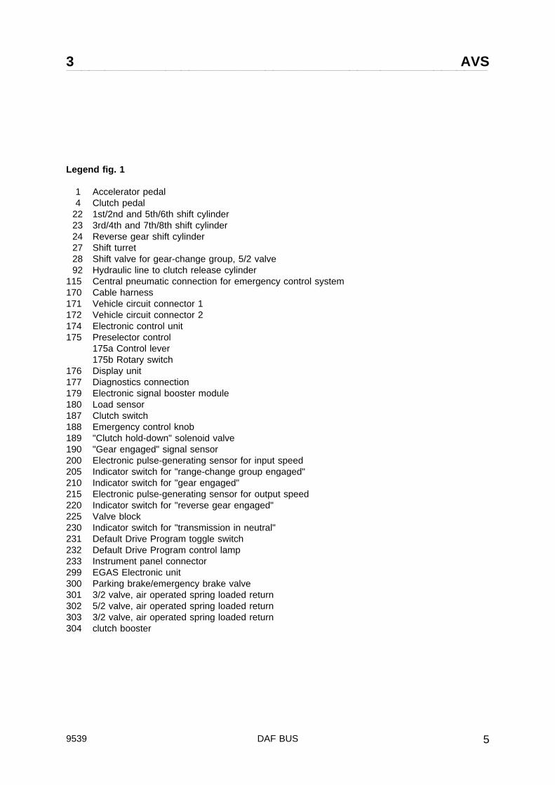
Legend fig. 1
1 Accelerator pedal4 Clutch pedal
22 1st/2nd and 5th/6th shift cylinder23 3rd/4th and 7th/8th shift cylinder24 Reverse gear shift cylinder27 Shift turret28 Shift valve for gear-change group, 5/2 valve92 Hydraulic line to clutch release cylinder
115 Central pneumatic connection for emergency control system170 Cable harness171 Vehicle circuit connector 1172 Vehicle circuit connector 2174 Electronic control unit175 Preselector control
175a Control lever175b Rotary switch
176 Display unit177 Diagnostics connection179 Electronic signal booster module180 Load sensor187 Clutch switch188 Emergency control knob189 "Clutch hold-down" solenoid valve190 "Gear engaged" signal sensor200 Electronic pulse-generating sensor for input speed205 Indicator switch for "range-change group engaged"210 Indicator switch for "gear engaged"215 Electronic pulse-generating sensor for output speed220 Indicator switch for "reverse gear engaged"225 Valve block230 Indicator switch for "transmission in neutral"231 Default Drive Program toggle switch232 Default Drive Program control lamp233 Instrument panel connector299 EGAS Electronic unit300 Parking brake/emergency brake valve301 3/2 valve, air operated spring loaded return302 5/2 valve, air operated spring loaded return303 3/2 valve, air operated spring loaded return304 clutch booster
9539 DAF BUS 5

AVS 3
2. GENERAL DESCRIPTION:
The operation of manual gearbox requires the use of a gear lever. The handle and gearbox areusually connected by a shift rod or switch cables.This system has certain advantages:- it is simple and reliable;- through the handle, the driver feels what the gearbox is doing (it cracks when the wrong gear
is selected and the handle cannot be placed in the correct position if the box does not changeinto this gear).
The system also has a number of limitations, such as:- restricted distance between the handle and the gearbox;- restricted weight of system of rods;- strength required to engage gear in synchronized gearbox;- required strength can only be produced if the handle is large enough;- large handle takes up a lot of space;- placement of handle is critical in a system of rods;- to prevent wear, system of rods should be oiled regularly;- sealing of the handle in the floor requires extra attention in a system of rods.
It is especially in a bus undercarriage in which the distance between the driver and the gearbox islarge and when comfort during gear change plays an important role, that a system of rods of cablesshould not be used.
Figure 1 shows an overview of the most important AVS components.
AVS cancels the handle’s resistance and the gearbox’s mechanic force during gear change. Thedriver operates the gearbox by means of a small control unit which has three drive modes (the so-called DNR-switch) pos. 175b and a control handle pos. 175a. The control unit consists of a numberof switches which convert the driver’s commands into electric signals. All signals are transported tothe EST 14 unit. When all signals are present and correct, the EST 14 unit will make sure that thecorrect actions are carried out after depression of the clutch. The solenoid switch valve operates oneof the three air cylinders 22, 23 or 24, which will engage the correct gear. The use of AVS herebyenhances comfort during gear change and limits the space that is required.First, the DNR-switch 175b enables the driver to choose between the (2nd) forward gear (drivemode D) or the reverse gear (R). Then the clutch should be depressed, after which the systemslows down the primary and secondary shaft and the preselected gear is engaged.When drive mode D has been selected on the rotary switch, the clutch should be depressed toinitiate the gear change in the gearbox. The clutch plate should disengages completely, thusdisconnecting the drive cable from the motor. To this end, a clutch booster is used, which operatesair valve 303 during disengagement of the plate. This air valve at its turn operates electric switch187, which transmits the signal "disengaged" to the AVS system. The electronic unit 174 will nowtransmit a switch command after which the switch cylinder involved is aerated and the preselectedgear is engaged. Both the preselected gear and the engaged gear are at all times visible on thedisplay 176.A disadvantage of the use of the control handle is that the driver does not feel what is happening inthe gearbox. Therefore, a sensor 190 is built into the clutch system. Through pulses in the clutchpedal, the driver feels if the clutch has indeed been engaged and knows if he can release the clutchpedal. If the driver releases the clutch pedal before the gear has been engaged and before thefeedback signal has been transmitted, valve 189 leaves the clutch disengaged until the signal "gearengaged" has been transmitted.
DAF BUS 95396

3 AVS
When the clutch pedal is released, the air in the system drops and gear change is no longerpossible.The electropneumatic nature of the system enables the use of a number of shift securities. Withoutsecurities of any kind, the whole system would go down if, for example, the power supply fuse weredefective.Therefore, a number of securities and functions have been incorporated into the system and inaddition to the default drive program, a complete pneumatic emergency control system helps copewith all possible situations. This is why the control system is rather complicated.
The system can be roughly divided into 3 parts:A The main switch system. This is the actual control system in which gears are preselected and
engaged depressing the clutch pedal - without use of the control lever.
B The default drive program enables gear change when one of these switches is defective:1. gear engaged2. transmission in neutral3. range group engaged.In this case, all gears are engaged through the main switch system by operating the controlhandle rather than automatic preselection.
C The emergency control system in case the main switch system goes down.
In the following description, the working of all components that were used will be dealt with in detailand all sub-situations which may occur while driving are discussed successively.
9539 DAF BUS 7

AVS 3
3. DESCRIPTION OF COMPONENTS
3.1 Control unit:The control unit fig. 2 consists of a spring-loaded control lever, which can be pushedforward (+) for shifting up, backwards (-) forshifting down or sideways to the left (N) forputting the transmission in neutral, and of arotary switch with the following modes: D forforward gears, N for transmission in neutraland R for reverse gear.The control unit is fully electrical and isattached to the cable harness with a 12-poleconnector. This paragraph describes theoperation of the switches and the controlunit’s output signals.
Fig. 2
DAF BUS 95398

3 AVS
When turning the rotary switch (or DNRswitch) fig. 2, the voltages shown in table Iare generated. The switches that areoperated are also indicated.
Table I Overview rotary switch* = 24 volt
OUTPUT SIGNAL PRESELECTORSWITCH
AD1 AD2 AD3
CONNECTOR PIN 3 4 2
WIRE 4833 4832 4690
POSITIONPRESELECTOR SWITCH
OPERATED SWITCH
D S1 *
N S1 *
R S1 *
- Neutral, pin 2 carries 24 V if the emergency control switch 188 is in position "aus" or neutralswitch E500 is closed (input voltage pin 1 and the DNR switch is put in neutral).
Upon operation of control lever 2B, the voltages indicated in table 2 are generated.
Table II Overview control lever
OUTPUT SIGNALPRESELECTOR SWITCH
OPERATED SWITCH
AD4 AD5 AD7 S5 S6 S7
CONNECTOR PIN 6 7 9
WIRE 4830 4829 4828
CENTRAL POSITION *
SHIFT UP (+) * * X
SHIFT DOWN (-) * * X
NEUTRAL (N) X
NOTE: - All output signals and operated switches for the control unit can be found in tableI and II.
- The control unit receives 24 V through pin 10, wire 4827 if the emergency controlswitch 188 is put in position "aus".
- Pin 12 is connected to the mass, but is not use internally.
9539 DAF BUS 9

AVS 3
Fig. 3
DAF BUS 953910
3 AVS
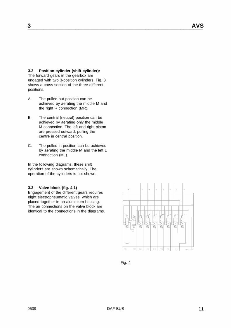
3.2 Position cylinder (shift cylinder):The forward gears in the gearbox areengaged with two 3-position cylinders. Fig. 3shows a cross section of the three differentpositions.
A. The pulled-out position can beachieved by aerating the middle M andthe right R connection (MR).
B. The central (neutral) position can beachieved by aerating only the middleM connection. The left and right pistonare pressed outward, pulling thecentre in central position.
C. The pulled-in position can be achievedby aerating the middle M and the left Lconnection (ML).
In the following diagrams, these shiftcylinders are shown schematically. Theoperation of the cylinders is not shown.
3.3 Valve block (fig. 4.1)Engagement of the different gears requireseight electropneumatic valves, which areplaced together in an aluminium housing.The air connections on the valve block areidentical to the connections in the diagrams.
Fig. 4
9539 DAF BUS 11
AVS 3
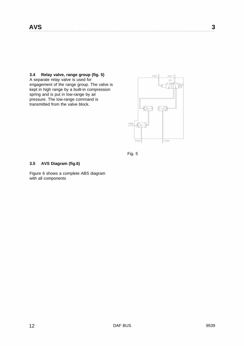
3.4 Relay valve, range group (fig. 5)A separate relay valve is used forengagement of the range group. The valve iskept in high range by a built-in compressionspring and is put in low-range by airpressure. The low-range command istransmitted from the valve block.
3.5 AVS Diagram (fig.6)
Figure 6 shows a complete ABS diagramwith all components
Fig. 5
DAF BUS 953912

3 AVS
Fig. 6
9539 DAF BUS 13

AVS 3
3.5 Electronic unit EST 14 (fig. 7)The electronic unit EST 14 controls theoperation of the AVS shift system (fig. 1 pos.174).
On the basis of input information from:- preselection switch- sensor drive- sensor output shaft- switch "range group engaged"- switch "gear engaged"- switch "transmission in neutral"- clutch switch- load sensor load signal (digital EMS)
(analogue) eg. Egas- compression (option)
retarder switch
the unit calculates the vehicle’s speed, motorload and acceleration or deceleration.
On the basis of this information, the systemdetermines the right gear for each situation.If the determined gear does not coincide withthe engaged gear, the display will show agear change advice. At the same time, thesystem is prepared for gear change, so thatoperation of the clutch switch results in thecorrect gear’s engagement.
The following functions are also incorporatedin the EST 14:- information supply to the display- system protection against too fast or
incorrect gear change- error registration plus readout possibility- default drive program
Fig. 7
DAF BUS 953914

3 AVS
4. SYSTEM DESCRIPTION
4.1 Ignition key lockingIf the vehicle is parked with one of the gears still engaged, the following could happen. Because ofair leakage, the air pressure might become too low to operate the clutch pedal, which results in theabsence of the release AVS signal. Without air, the gearbox cannot be put in neutral, unless theshift lever on the box is pushed in neutral position by hand via the repair hatch. Normally, thevehicle cannot be started.Therefore, a separate ignition lock has been fitted, in which the ignition key can only be turned fromposition 2 to position 0 if the gearbox is in neutral position. When the transmission is in neutral, theignition key locking (fig. 6) C539 is raised and the key can be turned to the 0 position. The enginewill automatically stop if the key is turned to positions 1 and 0. The voltages on engine stop valveB078 is disconnected, pulling the fuel pump in stop position.
4.2 Start securityThe ignition key locking also prevents the driver from starting the engine if not all starting conditionshave been met.If the transmission is not in neutral or if the DNR-switch is not in neutral position, relay contact G039is de-energized and the vehicle cannot be started.
4.3 Neutral position checkThe connection between control unit and gearbox is fully electrical. This means that it is not alwaysclear if the gearbox is in fact in neutral position. Therefore, the gearbox has been fitted with aneutral switch (fig. 1 pos. 23 or fig. 6 E500), which transmits the neutral signal to the EST 14 unit,which on its turn shows the neutral signal N on the display when the gearbox is in neutral (vehiclespeed under 10 km/h) and the ignition key is in position 2.
4.4 Output speed sensorThe signal of output speed sensor fig. 1 pos. 215 is used for registration of vehicle speed.
4.5 Clutch operationIf you try to put a manual gearbox in reverse gear but the clutch does not engage fully, you canhear a "grinding noise".This "grinding" is produced because the non-rotating sleeve is pushed against the reverse gearwheel.Compared with the forward gears, the reverse gear is not synchronized.The AVS system is activated by means of the clutch switch. The clutch signal is present when theclutch booster supplies air to the clutch switch (E531) via a valve (V6). This valve is integrated in theclutch booster.The clutch switch transmits the signal to the EST 14.The clutch booster’s stroke disengages the clutch, whereafter the clutch switch can be operated.If the above-described is to function correctly, there should be no air in the clutch system.
Note:If the hydraulic part of the clutch operation is not well-vented, the clutch plate will not disengagesufficiently and gear change will not pass correctly. A grinding noise is produced during gearchange.
Warning!As the forward gear is synchronized, the vehicle can start to move if the hand brake is not applied.
9539 DAF BUS 15

AVS 3
4.6 Default drive programThe AVS system needs information from a number of sensors and switches. If one of theseswitches is defective, or if the switch’s signal does not reach the AVS control unit, the AVS systemwill no longer operate.The AVS system can then be switched to the default drive program. In this program, the switches’signals are not required.
The sensors on the gearbox which send information to the control unit are:- neutral switch- gear engaged switch- range group switch- sensor input speed- sensor output speed.
The default drive program should only be used if:1. the gearbox is not mechanically damaged;2. there is sufficient air pressure for the system (min. 6.5 bar);3. the display shows one of the error codes mentioned in the table below:
ERROR NUMBER(DECIMAL)
COMPONENT
61 neutral switch interrupted
62 gear engaged switch interrupted
63 gear engaged switch closed
64 range group switch closed
65 range group switch interrupted
67 neutral switch closed
The default drive program is activated by a special toggle switch fig. 1 pos. 6, fig. 6 C665. All gearscan now be engaged manually through the control lever, like in a manual gearbox. Push the gearlever forward (+) if you want to shift up and push the lever backwards (-) if you want to shift down.The engaged or preselected gear is shown on the display (fig. 1 pos. 176, fig. 6 B530), together withthe spanner symbol. Also, the control light on the SWS panel (fig. 6 pos. D582) is on, indicating theactivation of the default drive program.
- Once the default drive program is activated, resetting toggle switch C665 does not deactivate tothe normal drive program until the power supply to the EST-14 has been down.
- If the neutral switch does not close, starting and stopping the engine is not possible since wire4690 is not powered. Use the emergency switch as described below to power wire 4690 directlyand reset it to "AVS" after the engine is started.
DAF BUS 953916

3 AVS
Fig. 8
4.7 Emergency control system (fig. 8)Fig. 8 shows a schematic overview of theemergency control system. Each electricsystem, however well-made, has fragilewiring and connections. It is possible thatbecause of one defective connection, noneof the gears can be engaged. Therefore, aseparate emergency system has beenadded. This emergency system works solelyon air.The emergency control system enablespneumatic gear change in the gearbox bymeans of the emergency system’s controlknob (fig.1 pos. 28, fig. 8 C664). With thisknob, the neutral position N, first (1) andsecond (2) gear and the reverse (R) can beengaged without intervention of electriccomponents. The shift cylinder corres-ponding to the control knob’s position isaerated. When the forward or reverse gear isengaged, the relay valve high low (fig.1 pos.34, fig. 8 V4) is activated in low range.The gears below correspond to the positionson the control knob:
position on knob engaged gear1 22 4R RN N
9539 DAF BUS 17

AVS 3
Under no circumstance should the AVSsystem be able to work if the emergencysystem is activated. Therefore, a switch 1-3is opened when switch C664 is operated.This cuts the AVS system’s voltage. Whenthe emergency switch is put in neutralposition, contact 2-5 is closed, thus making itpossible to start the engine.The emergency system is also protectedagainst incorrect gear change. This is donein the following way:- The first gear or reverse gear can only be
engaged if the vehicle has come to anabsolute stand-still. To this end, theemergency system is accessed via switchvalve V2, which is operated through switchvalve V2 by park brake valve V5.
- Gears can only be engaged if the clutchplate is disengaged (clutch pedal ispressed down). The required air comesfrom switch valve V6, which is operated bythe clutch booster.This method’s plus is that when theemergency system is activated, the drivercan change gears without having to applythe park brake all the time. Switch valveV1 is in emergency switch position andremains in this position until the AVSsystem can be activated again, pressingvalve V1 in its original position.
DAF BUS 953918

3 AVS
Fig. 9
4.8 Starting the engine (fig. 9)- Park brake applied- Control knob emergency system in "Aus"
position- Default drive program switch off- Main switch G053 on- Ignition key in lock, position 2, "ignition on"- Rotary switch control unit in position N,
("N" indicated on display)- Gearbox in neutral (E500 closed)- Ignition key blockage raised.
Starter motor B010 receives voltage viaignition lock C539 pos. 3, switch startforward/reverse C580, start locking relayG100, neutral position start relay G035 andstart relay G038.
9539 DAF BUS 19
AVS 3
5. SECURITY
The common starting and stopping procedures turn out to cause a number of unwanted situations ifcombined with an AVS system. To prevent these situations, a special electric circuit has beendevised so that:- the engine cannot be started if the gearbox is shifted into gear.- the key cannot be taken from the ignition if the gearbox is shifted into gear.- the engine cannot be cut of/by turning the ignition key backwards.- the main switch cannot be switched off while the engine is running.
5.1 Start security system Emergency system:If main switch G053 has not been activated, the ignition key can be inserted into the ignition lockand it can be turned as well. The key snaps into position 2 because the blocking relay is notenergized. As long as the main switch has not been activated, the engine cannot be started; the keycannot be taken from the ignition anymore.As soon as main switch G053 is activated and the ignition key is in position 2,- ignition relay G015 is energized so that all power consuming elements are connected to the power
source (connection point 15);- fuel valve B078 is actuated via fuse E109 so that the fuel pump is no longer pulled into the
stopping position and the engine can be used;- the neutral switch in C664 is connected to the power source via fuse E054 of the emergency
system, energizing relay G039 in neutral position;- G074 is energized, releasing ignition key locking.
Starting of the engine is achieved by turning the ignition key to position 3. The starting signal thengoes from contact 3, via switch C580, start locking relay G100, neutral position starting relay G039and starting relay G038 to the relay on starter motor B010. The starter motor is engaged.As soon as the engine engages, the dynamo will supply power, causing relay G100 to de-energize.The starting signal is interrupted and the starter motor is disengaged.
5.2 Start security system of the A.V.S. system:If the control knob of emergency system C664 is in the "Aus" position, the switch is closed and thecontacts 1, 3 and 4 are connected. This supplies power to:- switch E531, which is operated by the clutch booster- contact 20 of the electronic unit- contact 10 of control unit C668- control switch C665 of the default drive program
Because the rotary switch is in position "N", according to table 1, switch S1 in control unit C688 isclosed, which causes power to go to contact 2, relay G074 to be energized and the ignition keylocking to be lifted.
DAF BUS 953920

3 AVS
6. ADJUSTING
6.1 Adjusting neutral switch E500Neutral switch E500 is a break-switch. Fig. 1pos. 23, fig. 10 shows the switch as mountedon the gearbox. If this switch has to bereplaced, the replacement has to be adjustedby mounting it with a distance washer of thecorrect thickness. Use a feeler gauge andcontinuity testing lamp to determine thecorrect thickness of the washer.
- Remove distance washer from under theneutral switch.Warning! The ball (3) may fall out if theswitch is dismounted.
- Shift switch rod into neutral.- Screw in the switch until the signal just
disappears (test the switch with acontinuity testing lamp). If a testing lamp isused, the light will go out.
- Measure distance B with two feeler gauges(in connection with possible toppling of theswitch).
- Find the correct thickness of the distancewasher in the table below.
- Clean the surfaces of grease.- Mount the switch and the distance washer
with tightening torque 50 Nm
Fig. 10
1. Neutral switch2. "Gear engaged" switch3. Ball
9539 DAF BUS 21

AVS 3
Table for the aluminium distance washer, mounted without lubrication.
Distance B 0.4 0.5 0.6 0.7 0.8 0.9 1.0 1.1 1.2 1.3 1.4 1.5 1.6 1.7
Distancewasher
1.8 1.8 2.0 2.0 2.2 2.2 2.4 2.4 2.6 2.6 2.8 2.8 3.0 3.0
Check correct operation of the switch:- gearbox in neutral: light on;- gearbox in gear: light off.
6.1 Adjusting range group switchThe switch for the range group is a break-switch and is identical to the neutral switch.
Fig. 11 shows the position of the switch asmounted on the gearbox. When replaced,the switch does not have to be adjusted, buthas to be mounted with the supplieddistance washer.
Follow the steps below if adjustment isrequired:- Remove the distance washer from under
the neutral switch.- Put the switch shaft into middle position
with the aid of compressed air.- Remove connection p25 and p26 on the
cylinder of the range group.- Briefly aerate p25 or p26 until the gap in
the control pin is visible for the entirediameter of the switch shaft. The switchshaft is now in the middle position.
- Screw in switch until signal is lost.- Measure distance D with two feeler
gauges (in connection with possibletoppling of the switch).
- Suppose D = 2.6 mmdistance washer Z thickness = D - (0.8 +0
+0.2) mmmaximum thickness distance washer =2.6 - 0.8 = 1.8 mm.minimum thickness distance washer =2.6 - 1.0 = 1.6 mm.Choose the correct distance washer.The aluminium washers can be supplied inthe following thicknesses:1.0 - 1.2 - 1.4 - 1.6 - 1.8 - 2.0 - 2.2 - 2.4 -2.6 - 2.8 - 3.0.
fig. 11
DAF BUS 953922
3 AVS
- Clean the surfaces of grease and installthe switch and washer.Tightening torque switch = 50 NmTightening torque threaded bush = 50 Nm
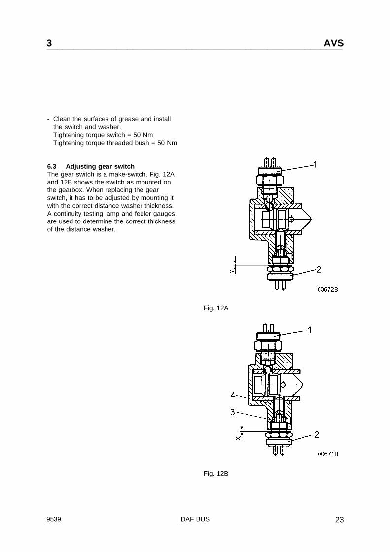
6.3 Adjusting gear switchThe gear switch is a make-switch. Fig. 12Aand 12B shows the switch as mounted onthe gearbox. When replacing the gearswitch, it has to be adjusted by mounting itwith the correct distance washer thickness.A continuity testing lamp and feeler gaugesare used to determine the correct thicknessof the distance washer.
Fig. 12A
Fig. 12B
9539 DAF BUS 23

AVS 3
Determination of the thickness of the distance washer.
1 Shift into 1st gear with default drive program.2 Screw in switch until testing light goes on (switch closed).3 Activate all gears one by one. Check if the testing lamp goes on for all gears.4 Repeat step 2 and 3 if the testing lamp does not burn for one of the gears.5 Shift gearbox into neutral.6 Start engine. Shift into reverse and slowly release clutch to verify that reverse gear is selected and
turn engine off. Repeat step 2 if the testing lamp does not burn.7 Measure distance X with two feeler gauges (in connection with possible toppling of the switch).8 Find the correct thickness of the distance washer in the table below.
Table for the aluminium distance washer, mounted without lubrication.
DistanceX
3.3 3.2 3.1 3.0 2.9 2.8 2.7 2.6 2.5 2.4 2.3 2.2 2.1 2.0 1.9 1.8
Distancewasher
2.6 2.4 2.4 2.2 2.2 2.0 2.0 1.8 1.8 1.6 1.6 1.4 1.4 1.2 1.2 1.0
Verification of the adjustment.
9 Shift into neutral.Screw in switch to distance Y. Signal should not come in.
- Horizontally mounted neutral switch.Distance Y = X - 1 mm
- Neutral switch mounted in 45° angle.Distance Y = X - 1.2 mm
Example:Horizontal version.Distance X = 2.6 mmDistance Y = 2.6 - 1.0 = 1.6 mm
Further check.
10 The difference between X and Y must be equal to or larger than 0.3 mm (X - Y ≥ 0.3)
Clean the surfaces of grease and install the switch and correct distance washer with a 50 Nmtightening torque. If the difference between X and Y complies with this.Check the complete adjustment procedure again if X - Y < 0.3 mm.
DAF BUS 953924
3 AVS
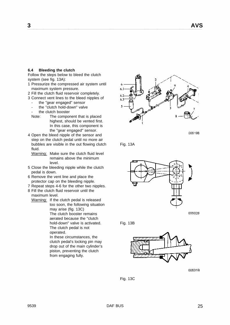
6.4 Bleeding the clutchFollow the steps below to bleed the clutchsystem (see fig. 13A):1 Pressurize the compressed air system until
maximum system pressure.2 Fill the clutch fluid reservoir completely.3 Connect vent lines to the bleed nipples of
- the "gear engaged" sensor- the "clutch hold-down" valve- the clutch boosterNote: The component that is placed
highest, should be vented first.In this case, this component isthe "gear engaged" sensor.
4 Open the bleed nipple of the sensor andstep on the clutch pedal until no more airbubbles are visible in the out flowing clutchfluid.Warning: Make sure the clutch fluid level
remains above the minimumlevel.
5 Close the bleeding nipple while the clutchpedal is down.
6 Remove the vent line and place theprotector cap on the bleeding nipple.
7 Repeat steps 4-6 for the other two nipples.8 Fill the clutch fluid reservoir until the
maximum level.Warning: If the clutch pedal is released
too soon, the following situationmay arise (fig. 13C)The clutch booster remainsaerated because the "clutchhold-down" valve is activated.The clutch pedal is notoperated.In these circumstances, theclutch pedal’s locking pin maydrop out of the main cylinder’spiston, preventing the clutchfrom engaging fully.
Fig. 13A
Fig. 13B
Fig. 13C
9539 DAF BUS 25
AVS 3
Replacing a shift cylinder:Two identical shift cylinders are mounted ontop of the gearbox (fig. 1 pos. 22 and 23).The cylinder connected to the long gearlever operates gears 1-2 and 5-6. Thecylinder that is connected to the short gearchange lever shifts gears 3-4 and 7-8.The integrated reverse gear’s shift cylinder(fig. 1 pos. 24) clearly is different from theseshift cylinders. Replacement of this cylinderwill not be discussed here.
First, the gear change levers should bemounted as described below (fig. 13B). Theshort gear lever should be mounted on thehollow clutch shaft first, in such a way thatthe marks on the switch are on the same linewith the marks on the gear lever.
This lever’s fixing bolt should first betightened at 30 Nm, and finally at 46 Nm.Lock the gear change lever with the lock nutand tighten it at 40 Nm.The long gear change lever is connectedusing the same procedure, the finaltightening torque of 30 Nm can, however, beused directly.
DAF BUS 953926
3 AVS
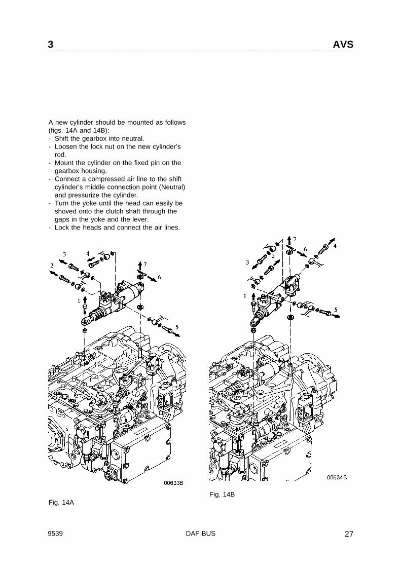
A new cylinder should be mounted as follows(figs. 14A and 14B):- Shift the gearbox into neutral.- Loosen the lock nut on the new cylinder’s
rod.- Mount the cylinder on the fixed pin on the
gearbox housing.- Connect a compressed air line to the shift
cylinder’s middle connection point (Neutral)and pressurize the cylinder.
- Turn the yoke until the head can easily beshoved onto the clutch shaft through thegaps in the yoke and the lever.
- Lock the heads and connect the air lines.
Fig. 14AFig. 14B
9539 DAF BUS 27

AVS 3
6.5 Adjusting shift cylinder (long lever)1. Turn on the ignition.2. Aerate the AVS system in neutral position by setting the preselector switch to N and pressing
down the clutch pedal.
Note 1. The cylinder must remain aerated during adjustment.2. The gearbox must mechanically be set in neutral.3. The long gear change lever has a mark that has to correspond to the mark on
the clutch shaft.3. Turn the cylinder towards the long lever.4. Verify that the gaps in the yoke correspond to the gap in the long lever. If not, the length of
the cylinder must be changed.5. Change is carried out as follows:
Slide away the rubber boot and loosen the lock nut (22 mm). The shaft in the yoke can nowbe turned so that the gaps correspond.
6. Screw the nut on the yoke (70 Nm) after the length is changed.7. Mount the fitting bolt that connects the yoke and the lever stress-free (tightening torque 30
Nm).8. Lock the fitting bolt with a new check nut (tightening torque nut 40 Nm).9. Slide the rubber boot over the nut and the yoke ridge.
DAF BUS 953928

3 AVS
6.6 Adjusting shift cylinder (short lever)If the shift turret and the shift cylinder arereplaced simultaneously, the shift cylindermust be set in advance.The preset size (350 ± 1.5 mm) is set asfollows:
1. Turn on the ignition.2. Aerate the AVS system in neutral
position by setting the preselectorswitch to N and pressing down theclutch pedal.Note 1. The cylinder must remain
aerated duringadjustment.
2. The gearbox mustmechanically be set inneutral.
3. Verifying the size- The size can be changed by sliding
away the rubber boot and looseningthe lock nut (22 mm). The shaft inthe yoke can now be turned untilthe correct size is obtained.
- Screw the nut on the yoke (70 Nm).- Slide the rubber boot over the nut
and the yoke ridge.- Turn the cylinder towards the short
lever.- Turn the short lever, which is not
fixed to the clutch shaft, until thegaps in the yoke and the lever areon the same line and the fitting boltthat connects the lever and theyoke can be mounted stress-free at30 Nm.
- Lock the fitting bolt with a newcheck nut (tightening torque 40Nm).
- Clamp the short lever on the clutchshaft by fastening the M10 bolt andnut (tightening torque 46 Nm).
Note The short lever is meant forone-time use only; it can only beclamped around the clutch shaftonce.
Fig. 15
9539 DAF BUS 29

AVS 3
6.7 Adjusting outgoing shaft speedsensor (fig. 16A, 16B, 16C)
Adjustment of the outgoing shaft speedsensor (fig. 1 pos. 215) takes place asfollows:- remove the sensor from the gearbox (fig.
16A)- Measure distance X between the gearbox
housing and one of the teeth.Note that the tooth must be in the centreof the bore.
- Subsequently, measure distance Y (fig.16B).
- The margin is then X - Y, which should be1.2 ±0.4 mm (fig. 16C).
- Adjust, if necessary, the measured marginby replacing the distance washer.
- Mount the sensor without sealingcompound.
Fig. 16A
Fig. 16B
Fig. 16C
DAF BUS 953930
3 AVS
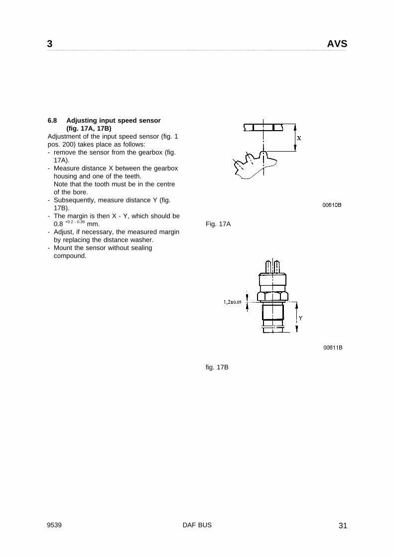
6.8 Adjusting input speed sensor(fig. 17A, 17B)
Adjustment of the input speed sensor (fig. 1pos. 200) takes place as follows:- remove the sensor from the gearbox (fig.
17A).- Measure distance X between the gearbox
housing and one of the teeth.Note that the tooth must be in the centreof the bore.
- Subsequently, measure distance Y (fig.17B).
- The margin is then X - Y, which should be0.8 +0.2 - 0.35 mm.
- Adjust, if necessary, the measured marginby replacing the distance washer.
- Mount the sensor without sealingcompound.
Fig. 17A
fig. 17B
9539 DAF BUS 31
AVS 3
7. AVS DIAGRAM
Figures 18 up to 31 shows the AVS diagram for the different situations
Fig. 18 Gearbox neutralFig. 19 1 st gear engagedFig. 20 2 nd gear engagedFig. 21 3 rd gear engagedFig. 22 4 th gear engagedFig. 23 5 th gear engagedFig. 24 6 th gear engagedFig. 25 7 th gear engagedFig. 26 8 th gear engagedFig. 27 reverse gear engagedFig. 28 Emergency control position 1 2 nd gear engagedFig. 29 Emergency control position 2 4 th gear emgagedFig. 30 Emergency control position N gearbox neutralFig. 31 Emergency control position R reverse gear engaged
DAF BUS 953932
3 AVS
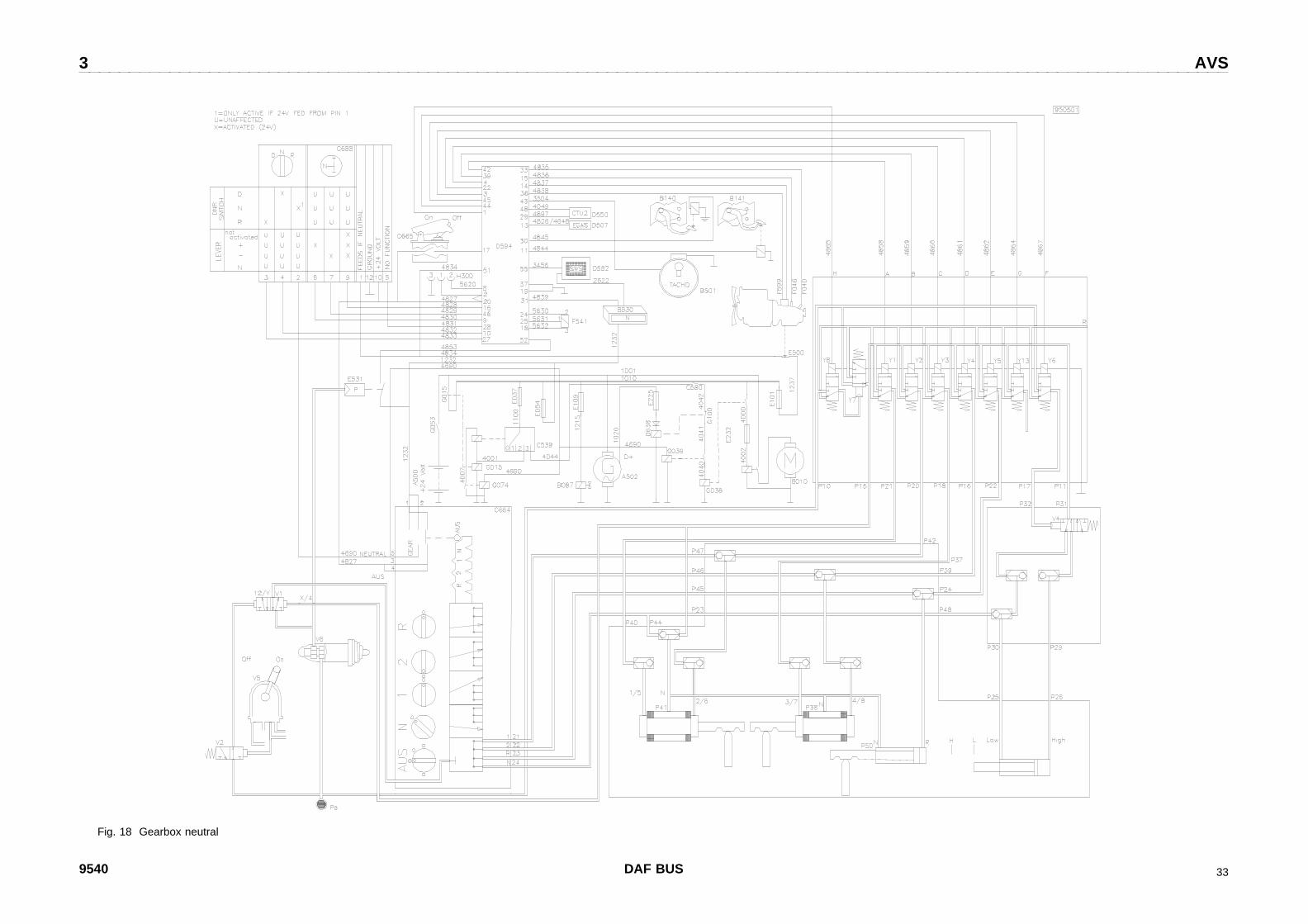
Fig. 18 Gearbox neutral
9540 DAF BUS 33


3 AVS
Fig. 19 1e gear engaged
9540 DAF BUS 35


3 AVS
Fig. 20 2e gear engaged
9540 DAF BUS 37


3 AVS
Fig. 21 3e gear engaged
9540 DAF BUS 39

3 AVS
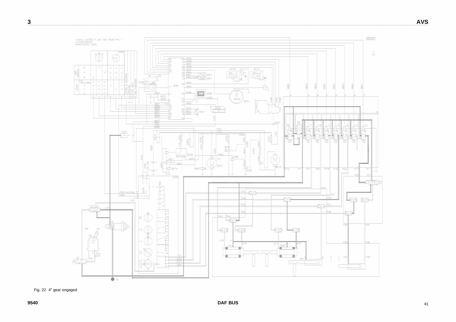
Fig. 22 4e gear engaged
9540 DAF BUS 41

3 AVS
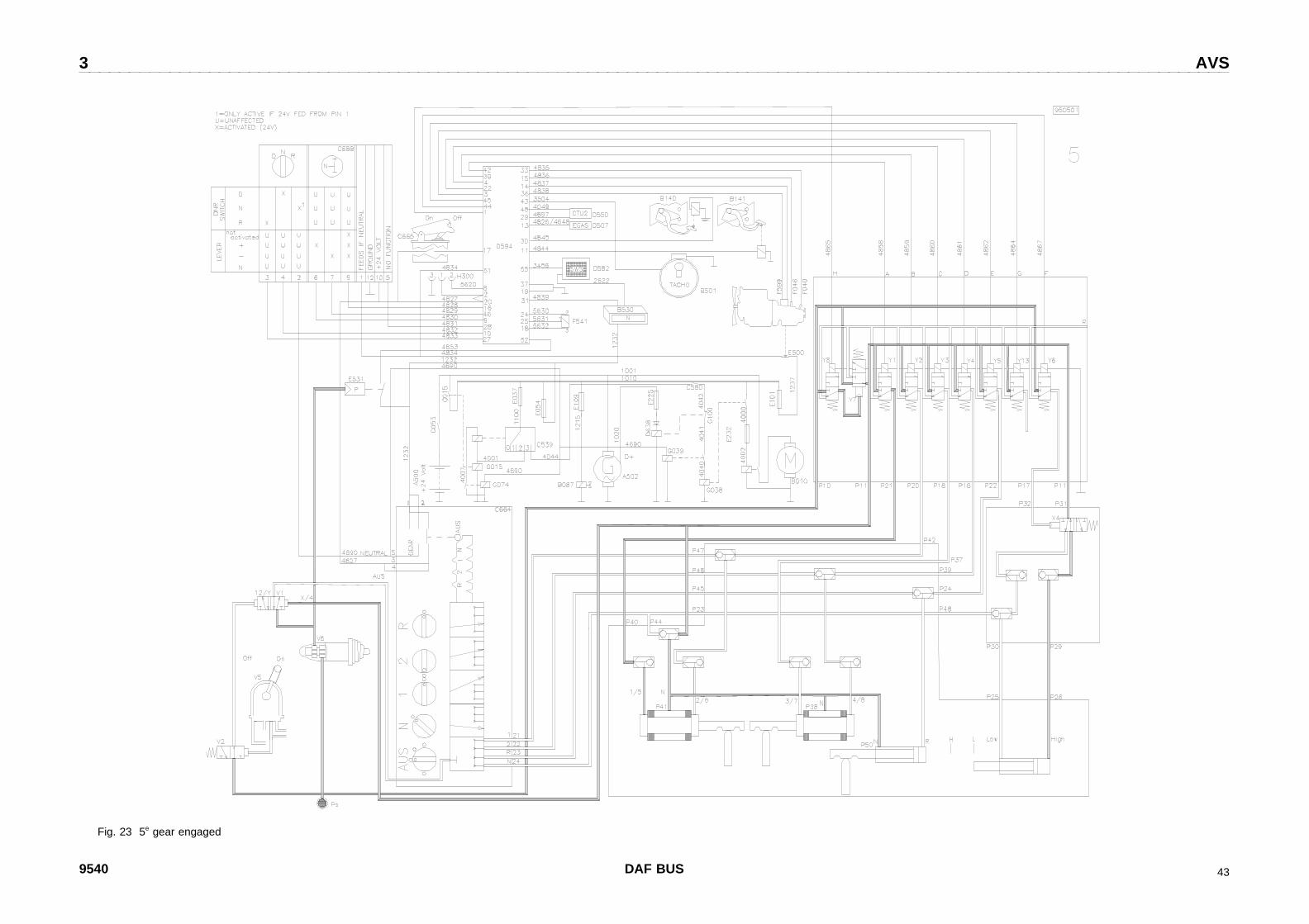
Fig. 23 5e gear engaged
9540 DAF BUS 43


3 AVS
Fig. 24 6e gear engaged
9540 DAF BUS 45


3 AVS
Fig. 25 7e gear engaged
9540 DAF BUS 47


3 AVS
Fig. 26 8e gear engaged
9540 DAF BUS 49


3 AVS
Fig. 27 Reverse gear engaged
9540 DAF BUS 51

3 AVS
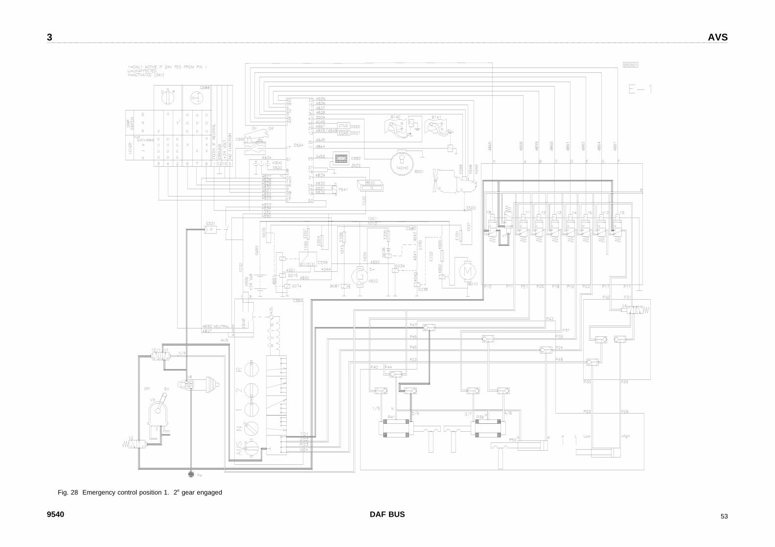
Fig. 28 Emergency control position 1. 2e gear engaged
9540 DAF BUS 53

3 AVS
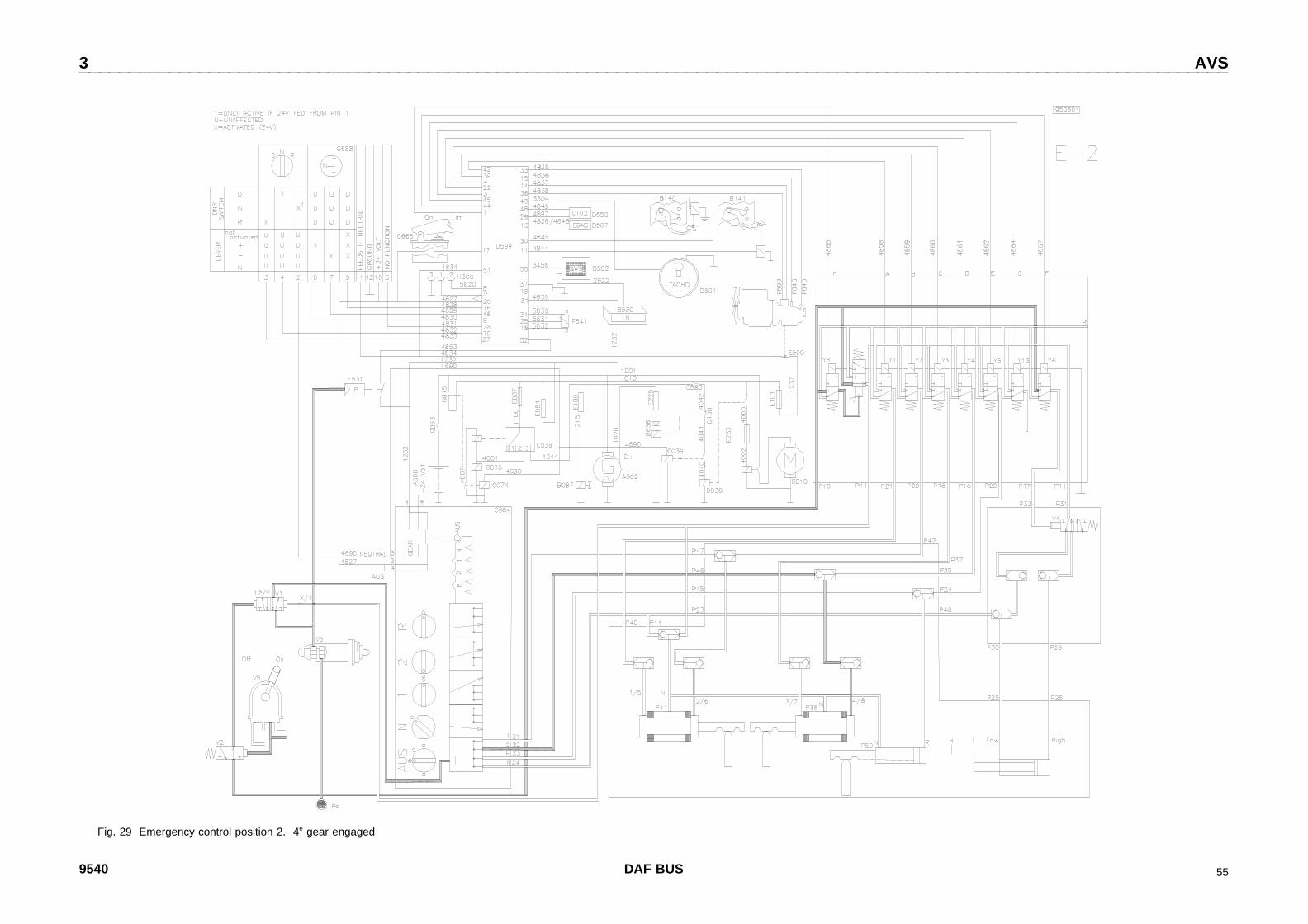
Fig. 29 Emergency control position 2. 4e gear engaged
9540 DAF BUS 55


3 AVS
Fig. 30 Emergency control position N. Gearbox neutral
9540 DAF BUS 57


3 AVS
Fig. 31 Emergency control position R. Reverse gear engaged.
9540 DAF BUS 59


3 AVS
8 AVS ERROR TABLE
AVS error messages are described in the following tables. Included are also possible causes, effectson the system, solutions and safety guidelines.System oriented errors cause an error number to show on the display, which can be viewedaccording to the procedure Default drive program in chapter 4.6.
8.1 Pneumatic/mechanical errors:
Error Possible cause Solution
Rattling or chattering duringshifting.
Clutch switch incorrectly adjustedor defective.
Use emergency switch to go tonearest repair shop
Reverse cannot be accessed atfirst attempt.
- Teeth out of mesh.- Air pressure too low.- Reverse engaged while vehicleis moving.
- Shift into reverseagain.
- Increase air pressure.- Stop vehicle and turn
rotary switch to "R"again.
One or more gears cannot beused.
- Air pressure too low.- System defective.- Clutch does not
disengage fully
- Increase air pressure.- Use emergency
switch to go tonearest repair shop.
- Follow directionsgiven by vehiclemanufacturer.
No feedback signal to clutchpedal.
- Clutch pedal not helddown.
- Pressure sensordefective.
- Air pressure too low.
- Press pedalcompletely downduring shifting andkeep it there untilfeedback signal canbe felt in the pedal.
- Find repair shop.Normal driving ispossible. Releaseclutch when displayshows new gear.
- Check air pressure.
9539 DAF BUS 33

AVS 3
Error Possible causes Solution
Engine cannot be started usingemergency switch.
- Emergency switch isnot in position "N".
- Fuse defective.
- Turn emergency switchto position "N".
- Replace fuse.
Gears cannot be selected withemergency switch.
- Not enough airpressure.
- Clutch not held down.- Gear position not
sufficiently aerated.
- Increase air pressure.- Depress clutch pedal
completely and keep itdepressed duringshifting.
- Depress clutch pedalat least 5 sec. in gearposition.
Selected gear in emergencyswitch is too high.
- Neutral position notsufficiently aerated(range group stillin pos. "fast").
- Depress clutch pedalat least 5 sec. inneutral position.
Engine cannot be started. - Fuse blown.- Gearbox is in gear.
- Replace fuse.- Shift gearbox into
neutral (use air fromexternal source ifnecessary).
Engine cannot be started usingemergency switch.
- Emergency switch notin position "N".
- Fuse defective.
- Turn emergency switchto "N".
- Replace fuse.
Gear cannot be selected usingemergency switch.
- Air pressure too low.- Clutch not held down.- Gear position
insufficiently aerated.
- Increase air pressurein air receiver.
- Depress clutch pedalcompletely and keep itdepressed duringshifting.
- Depress the clutch atleast 5 sec. in gearposition.
DAF BUS 953934

3 AVS
8.2 Electric/electronic errors:
Display Errornr.
Effect on system Action by driverSafety guidelines
N 35,55 No feedback signal to clutch pedal. Driving can be continued.Follow directions on display.Press clutch pedal when new gear is displayed.
N 62,63,64,65
Gearbox doesn’t shift gears; whenin reverse: teeth out of mesh.
Check air pressure. If necessary: continuedriving with default drive system.
N 75,76 Gearbox doesn’t change gears. Use emergency switch to drive to nearest repairshop.
N 91,92,93
No effects. Driving can be continued.Have errors repaired.
34,54 Default drive light is constantlyburning or doesn’t work.
Driving can be continued.Have errors repaired.
71,72,73,74
AVS drive program not optimallyadjusted.
Driving can be continued.Have errors repaired.
77 Driving signal is not present. Driving can be continued. Shifting down onlyallowed to maximum nominal rpm.
78 Driving signal not present. Longerdelay when shifting to startinggear.
Driving can be continued.Reverse gear can only be selected/deselectedwhile stationary and when ignition is on.
N 84 Defective control device. Continue driving if possible.Shifting down only allowed to maximum nominalrpm.
N 88 Default drive program is active. Control (refer to chapter 4).
N 21 Starting gear cannot be selected. Use emergency system to find nearest repairshop.
N 23 1st and 5th gear cannot be selected. Driving can be continued with manualpreselection.Warning! 1st gear cannot be selected as startinggear.
N 24 2nd and 6th gear cannot beselected.
Driving can be continued with manualpreselection.Warning! 2nd gear cannot be selected as startinggear.
N 25 3rd and 6th gear cannot beselected.
Driving can be continued with manualpreselection.
N 26 4th and 8th gear cannot beselected.
Driving can be continued with manualpreselection.
N 27 Reverse gear cannot be selected. Select reverse using emergency switch.
9539 DAF BUS 35
AVS 3
Display Errornr.
Effect on system Action by driverSafety guidelines
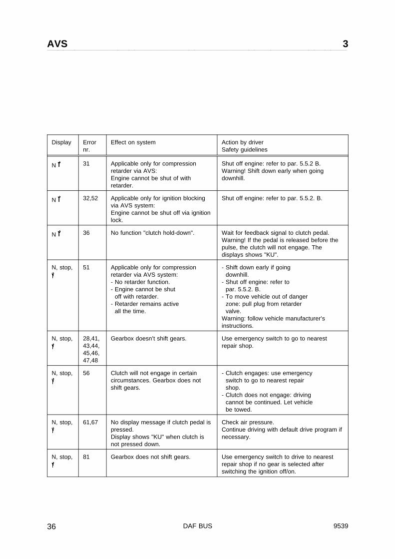
N 31 Applicable only for compressionretarder via AVS:Engine cannot be shut of withretarder.
Shut off engine: refer to par. 5.5.2 B.Warning! Shift down early when goingdownhill.
N 32,52 Applicable only for ignition blockingvia AVS system:Engine cannot be shut off via ignitionlock.
Shut off engine: refer to par. 5.5.2. B.
N 36 No function "clutch hold-down". Wait for feedback signal to clutch pedal.Warning! If the pedal is released before thepulse, the clutch will not engage. Thedisplays shows "KU".
N, stop, 51 Applicable only for compressionretarder via AVS system:- No retarder function.- Engine cannot be shut
off with retarder.- Retarder remains active
all the time.
- Shift down early if goingdownhill.
- Shut off engine: refer topar. 5.5.2. B.
- To move vehicle out of dangerzone: pull plug from retardervalve.
Warning: follow vehicle manufacturer’sinstructions.
N, stop, 28,41,43,44,45,46,47,48
Gearbox doesn’t shift gears. Use emergency switch to go to nearestrepair shop.
N, stop, 56 Clutch will not engage in certaincircumstances. Gearbox does notshift gears.
- Clutch engages: use emergencyswitch to go to nearest repairshop.
- Clutch does not engage: drivingcannot be continued. Let vehiclebe towed.
N, stop, 61,67 No display message if clutch pedal ispressed.Display shows "KU" when clutch isnot pressed down.
Check air pressure.Continue driving with default drive program ifnecessary.
N, stop, 81 Gearbox does not shift gears. Use emergency switch to drive to nearestrepair shop if no gear is selected afterswitching the ignition off/on.
DAF BUS 953936


